Air Shift Module User Manual
|
|
|
- Ernest Cooper
- 6 years ago
- Views:
Transcription

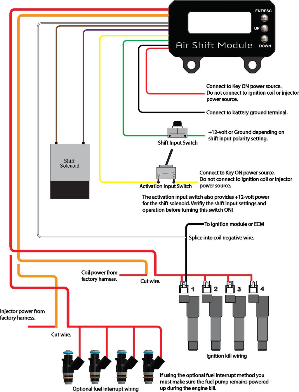
1 1 Air Shift Module User Manual Important leave the shift solenoid connector unplugged until you have configured the shift input polarity and verified correct operation!
2 2 These instructions are written to be comprehensive and detailed to make the installation of this product go as smoothly as possible. No instructions can be a substitute for the mechanical experience necessary to properly complete this project. Therefore, if after reviewing this document you have any doubts about your skills or experience we strongly urge you to seek professional assistance. Contents General Information About Page 3 Operational Overview Page 3 Important Information Page 4 Warranty Page 4 User Interface Overview Page 5 Set Operating Mode Page 5 Ignition Kill Operating Mode Set Engine Kill Time Page 6 Set Shift Count (number of gear positions) Page 6 Set Solenoid Advance Time Page 7 Set Shift Input Polarity Page 7 Auto Shift Operating Mode Set Auto Shift RPM Page 8 Set Engine Kill Time Page 6 Set Shift Count (number of gear positions) Page 6 Set Solenoid Advance Time Page 7 Set Tach Input Frequency (number of pulse per crankshaft revolution) Page 8 Set Shift Input Polarity Page 7 Installation Instructions Wiring Diagram Page 9 Additional Notes Coil Wiring with MSD Launch Master Page 10 Coil Wiring with Power Commander Ignition Module Page 10 Injector Wiring with Power Commander Page 10
3 3 About The RSR-ASM Engine Kill/Auto Shift module can be configured to operate as only engine kill or it may optionally be configured to operate as an auto shift with integrated engine kill. A built-in shift counter allows up to five gear shifts to be selected. This allows a different kill time and/or shift rpm for each gear. The RSR-ASM can be used to kill the engine using the ignition coil(s) or fuel injectors. A +12-volt activation input enables the shift count (and optionally auto shift) function and also provides power to the shift solenoid. Operational Overview Important always keep the activation input OFF until you have verified correct shift input operation and are ready to enable shifts. Important if the shift input is always ON without the shift button depressed check to make sure you have selected the correct shift input polarity! At power on the module will start into the selected operating mode, engine kill only or auto shift with engine kill. The selected shift input polarity will be configured and a check of the shift input is performed. If the shift input is ON at power up no engine kill or shifts will be allowed until the shift input turns OFF. The module is now ready to control engine kill and/or auto shift functions. The activation input must be ON to enable the shift solenoid output. Once the activation is input is ON a shift input signal will turn on the shift solenoid. The module will wait to enable the engine kill for the amount of time programmed in the solenoid advance time setting. This setting gives the shift solenoid time to open and begin pressurizing the shift cylinder before the engine kill occurs. If engine kill only mode is selected the gear count will increment only when the shift input is applied. If the module is configured for auto shift mode, the gear count will be incremented with either a shift input signal or when the programmed shift rpm is reached and an auto shift occurs. The shift input can be used to shift any time even when auto shift mode is selected. Once the gear positon is equal to the shift count setting the auto shift function will be disabled, however the shift input can still be used to shift. When the activation input is turned OFF the shift count will be reset to gear position one. When using auto shift mode if the engine rpm drops below 2000 rpm the shift count will be reset even if the activation input is ON. The engine kill function controls the positive voltage to either the ignition coils or the injectors. When the engine kill is active the voltage to the ignition coils or injectors will be turned off for the amount of kill time programmed. If the kill time is set to 0 no engine kill will occur.
4 4 Important Information Do not submerge in water or spray with a pressure wash system. Do not mount close to exhaust components or areas of high heat source. Do not mount in a location where wires and/or other objects may hit the programming buttons during operation. When using a conventional style ignition coil (Not Coil on Plug) you must use Static Suppression Ignition Wires with this Controller. It is the responsibility of the purchaser to follow all guidelines and safety procedures supplied with this product and any other manufactures product used with this product. It is also the responsibility of the purchaser to determine compatibility of this device with the vehicle and other components. Schnitz Racing assumes no responsibility for damages resulting from accident, improper installation, misuse, abuse, improper operation, lack of reasonable care, or all previously stated reasons due to incompatibility with other manufacturer's products. Schnitz Racing assumes no responsibility or liability for damages incurred from the use of products manufactured or sold by Schnitz Racing on vehicles used for competition racing. Schnitz Racing neither recommends nor approves the use of products manufactured or sold by Schnitz Racing on vehicles which may be driven on public highways or roads, and assumes no responsibility for damages incurred from such use. Schnitz Racing does not recommend nor condone the use of its products for illegal street racing. Warranty Schnitz Racing warrants to the original purchaser that the controller shall be free from defects in parts and workmanship under normal use for 180 days from the date of purchase. Schnitz Racing obligation under this warranty is limited to the repair or replacement of any component found to be defective when returned postpaid to Schnitz Racing. The Controller must be returned with evidence of place and date of purchase or warranty will be void. The warranty will not apply if the controller has been installed incorrectly, repaired, damaged, or tampered with by misuse, negligence or accident.
5 5 Engine Kill Mode Activation Input Status Shift Input Status Gear Position ACT= OFF SHFT= OFF GEAR = 1 IGN KILL MODE Enter and ESC Button Press and Hold for Enter Press and Release for ESC Up Button Down Button Auto Shift Mode Activation Input Status Shift Input Status Gear Position ACT= OFF SHFT= OFF GEAR = Enter and ESC Button Press and Hold for Enter Press and Release for ESC Up Button Down Button Engine RPM Set Operating Mode The operating mode determines if the module is in Engine Kill Only mode or Auto Shift Mode. To use the Auto Shift Mode the tach input wire must be connected and the proper tach input frequency selected. Use the RPM display to verify the correct RPM. Change Operating Mode 2 Press and release the Down button until ENGINE KILL MODE or AUTO SHIFT MODE is highlighted. 3 Press and hold the ENT/ESC button until the mode select menu opens. 4 Use the Up and Down buttons to select the desired operating mode. 5 Press and hold the ENT/ESC button to accept the selected operating mode. The module will reset and startup in the selected operating mode now. If no change is made the module will return to the setup menu. 6 Press and release the ENT/ESC button to exit without changing this setting. This will return to the setup menu. Press and release ENT/ESC to exit the setup menu if desired.
6 6 Set Engine Kill Time The engine kill time can be set for each gear shift. If the Shift Count setting is set to 1 only one kill time can be programmed. If the Shift Count setting is greater than 1 the number of kill time settings will be equal to the Shift Count setting. If the shift input is activated and the activation input is off an engine kill will occur. This provides a method to test this function (no kill will occur if the 1-2 kill time is set to 0). Once the activation is turned on each shift input sequence will increment to the next gear position up to the Shift Count setting. Valid range 0 to 150 milliseconds in 1 millisecond increments. Important - Once the activation input is on the shift solenoid will be enabled and the solenoid will be turned on with each shift input. Change Kill Time Setting(s) 2 Press and release the Down button until SET KILL TIME is highlighted. Note if the module is to Engine Kill Mode the SET KILL TIME will be highlighted when entering the setup menu. 3 Press and hold the ENT/ESC button until the kill time menu opens. 4 Use the Up and Down buttons to select the desired gear position kill time. 5 Press and hold the ENT/ESC button to enter edit mode for the selected kill time. 6 Use the Up and Down buttons to adjust the kill time. 7 Press and hold the ENT/ESC button until the new value is saved. 8 Press and release the ENT/ESC button to exit back to the kill time menu without saving the setting. 9 Press and release the ENT/ESC button to return to the setup menu, press and release again to return to the main screen. Set Shift Count The shift count setting determines the total number of gear shifts that you wish to use. Valid range 1 to 5. Change Shift Count Setting 2 Press the and release the Down button until SHIFT COUNT = X is highlighted. 3 Press and hold the ENT/ESC button to enter edit mode. 4 Use the Up and Down buttons to adjust the setting. 5 Press and hold the ENT/ESC button until the new value is saved. 6 Press and release the ENT/ESC button to exit without changing this setting. This will return to the setup menu. Press and release ENT/ESC to exit the setup menu if desired.
7 7 Set Solenoid Advance Time The solenoid advance setting determines the amount of that the shift solenoid is turned on before the engine kill occurs. This feature allows the air to begin filling the shift cylinder before the engine kill occurs. For most applications, the default setting of 20 milliseconds will work fine. If the shift solenoid is more than 10 inches away from the shift cylinder a longer advance time may be needed. Valid range 10 to 40 milliseconds in 1 millisecond increments. Change Solenoid Advance Time Setting 2 Press the and release the Down button until SOLENOID ADVANCE = X is highlighted. 3 Press and hold the ENT/ESC button to enter edit mode. 4 Use the Up and Down buttons to adjust the setting. 5 Press and hold the ENT/ESC button until the new value is saved. 6 Press and release the ENT/ESC button to exit without changing this setting. This will return to the setup menu. Press and release ENT/ESC to exit the setup menu if desired. Set Shift Input Polarity The shift input polarity setting determines whether the shift is active with a Ground or +12-volt input signal. Use the Shift Input Status readout on the display to ensure correct operation. Important leave the shift solenoid connector unplugged until you have configured the shift input polarity and verified correct operation! Change Shift Input Polarity Setting 2 Press the and release the Down button until SHIFT INPUT = X is highlighted. 3 Press and hold the ENT/ESC button to open the shift input polarity menu. 4 Use the Up and Down buttons to adjust the setting. 5 Press and hold the ENT/ESC button until the new value is saved. The module will reset and startup with the new shift input polarity selected. If no change is made the module will return to the setup menu. 6 Press and release the ENT/ESC button to exit without changing this setting. This will return to the setup menu. Press and release ENT/ESC to exit the setup menu if desired.
8 8 Auto Shift Operating Mode Set Auto Shift RPM The Auto Shift RPM can be set for each gear position. If the Shift Count setting is set to 1 only one RPM can be programmed. If the Shift Count setting is greater than 1 the number of RPM settings will be equal to the Shift Count setting. The shift rpm settings must be +/-2000 RPM of the 1-2 rpm setting. When adjusting the settings, this rule will be applied. When adjusting the 1-2 RPM setting the remaining settings will be automatically adjusted to satisfy this requirement. Always verify all of the desired RPM settings after adjusting the 1-2 rpm. The activation input must be on (+12-volt applied) to enable the auto shift function. If the shift input is applied before the auto shift RPM is reached a shift override will occur and the shift count (gear position) will be incremented. Once the gear position equals the shift count setting no more auto shifts are allowed, however the shift input can still be used to initiate a shift. The shift solenoid will remain on for a maximum of.4 second or the engine RPM drops 200 RPM below the shift RPM. Valid range 2000 to RPM in 10 RPM increments. Change Auto Shift RPM Setting(s) 2 Press and release the Down button until SET SHIFT TIME is highlighted. 3 Press and hold the ENT/ESC button until the shift rpm menu opens. 4 Use the Up and Down buttons to select the desired gear position shift rpm. 5 Press and hold the ENT/ESC button to enter edit mode for the selected shift rpm. 6 Use the Up and Down buttons to adjust the shift rpm. 7 Press and hold the ENT/ESC button until the new value is saved. 8 Press and release the ENT/ESC button to exit back to the kill time menu without saving the setting. 9 Press and release the ENT/ESC button to return to the setup menu, press and release again to Set Tach Input Frequency The tach input frequency setting determines the number of pulses the tach input receives per one revolution of the crankshaft. The exception is the "1 PULSE PER 2 REV" setting, this is used for modern fuel injected systems that only fire the sparkplug once every 2 revolutions of the crankshaft. Change Tach Input Frequency Setting 2 Press the and release the Down button until tach input frequency setting is highlighted. 3 Press and hold the ENT/ESC button to open the tach input frequency menu. 4 Use the Up and Down buttons to adjust the setting. 5 Press and hold the ENT/ESC button until the new value is saved. 6 Press and release the ENT/ESC button to exit without changing this setting. This will return to the setup menu. Press and release ENT/ESC to exit the setup menu if desired.
9 9
10 10 Coil Wiring with MSD Launch Master. The MSD Launch Master gets its +12v power from the ignition coil harness. You must install the MSD Launch Master into the stock wiring harness first then install the ASM harness in between the Launch Master harness and the ignition coils. This is to ensure power is not interrupted to the Launch Master, causing it to reboot at every shift Coil Wiring with Power Commander Ignition Module. The Power Commander Ignition Module gets its +12v power from the ignition coil harness. You must install the Power Commander Ignition Module into the stock wiring harness first then install the ASM harness in between the Ignition Module harness and the ignition coils. This is to ensure power is not interrupted to the Ignition Module, causing it to reboot at every shift. Injector Wiring with Power Commander. The Power Commander gets its +12v power from the fuel injector harness. You must install the Power Commander into the stock wiring harness first then install the ASM harness in between the Power Commander harness and the fuel injectors. This is to ensure power is not interrupted to the Power Commander, causing it to reboot at every shift.
The kit comes with a 100 psi sensor, solenoids and harness.
 AMS-500 V2 Boost Controller Overview The AMS-500 V2 Boost Controller is a time based graph style controller. It has a launch input which is used by transbrake input or clutch input. Both the activation
SCHNITZ MOTORSPORTS USER MANUAL AND INSTALLATION GUIDE PRO-MOD BATTERY VOLTS DIAGNOSTICS NOS PULSE FREQUENCY NOS DELAY TIME IN SECONDS
 SCHNITZ MOTORSPORTS DSC-CS "PRO-MOD" IGNITION CONTROLLER USER MANUAL AND INSTALLATION GUIDE COIL, (OPTIONAL) GA YELLOW, COIL, NEGATIVE GA WHITE, GA BLACK, SHIFT LIGHT +V OUTPUT PAGE 0 NOS ACTIVATION INPUT
SCHNITZ MOTORSPORTS PNC-202, 2-STAGE PROGRESSIVE NITROUS CONTROLLER USER MANUAL AND INSTALLATION GUIDE NOS PULSE FREQUENCY
 SCHNITZ MOTORSPORTS PNC-202, 2-STAGE PROGRESSIVE NITROUS CONTROLLER USER MANUAL AND INSTALLATION GUIDE NOS #2, FUEL SOLENOID(GROUND) 1GA PURPLE, PAGE 14 NOS #2 NITROUS SOLENOID(GROUND) 1GA PURPLE, PAGE
USER MANUAL AND INSTALLATION GUIDE ENGINE RPM AND NOS SHIFT COUNTER NOS DELAY TIME IN SECONDS NOS START PERCENT NOS FINAL PERCENT
 SCHNITZ MOTORSPORTS DSC-9PS "PRO-STREET" IGNITION CONTROLLER USER MANUAL AND INSTALLATION GUIDE SHIFT LIGHT POSITIVE PAGE 2 SHIFT LIGHT GROUND PAGE 2 NOS SOLENOID GROUND 1GA ORANGE, FUEL SOLENOID GROUND
USER MANUAL AND INSTALLATION GUIDE TIMER DELAY IN SECONDS SHIFT STYLE & SHIFT COUNTER TIMER DURATION NOS DELAY TIME IN SECONDS NOS START PERCENT
 SCHNITZ MOTORSPORTS DSC-TG0- "TOP-GAS " IGNITION CONTROLLER USER MANUAL AND INSTALLATION GUIDE COIL, (OPTIONAL) GA YELLOW, PAGE COIL, NEGATIVE GA WHITE, PAGE SHIFT LIGHT GROUND 0GA BROWN, PAGE 0 SHIFT
SCHNITZ. Racing DRY , Dry NOS System
 Table of Contents SCHNITZ DRY-3008-2, Dry System 1.0 General Safety Precautions Page 1 2.0 Important Notice Page 2 3.0 Warranty Page 2 4.0 Items Included in Kit Page 2 5.0 Power Commander Tuning Tips Page
DFS-1000 Wiring Diagrams and PC Software Installation.
 DFS-1000 Wiring Diagrams and PC Software Installation. For Technical Support Please contact your dealer or email seellc@mchsi.com 1 Important Information - When using a conventional style ignition coil
SCHNITZ. Racing SCB-PPI Programmable Power Interrupt Installation and Operation Instructions
 SCB-PPI Programmable Power Interrupt Installation and Operation Instructions Description The SCB-PPI Programmable Power Interrupt is a fully digital and programmable unit used to interrupt the coil charge
Lingenfelter Launch Control Module
 Installation Instructions For Lingenfelter Launch Control Module Adjustable Launch Controller & RPM Limiter For GM LSx Series Engines NOW With Timing Retard Mode PN: L4615297 1557 Winchester Road Decatur,
Thank you for your purchase Off-ROad NOtice: PROduct WaRNiNgs:
 Thank you for your purchase. Please, read the instructions and watch the video before installing the JMS Progressive N20 Controller. Configuration and installation videos are available online: www.jms-nos.com.
# Traction Control Window Switch
 1 INSTRUCTIONS # 82085 Traction Control Window Switch Thank you for choosing products; we are proud to be your manufacturer of choice. Please read this instruction sheet carefully before beginning installation,
Lingenfelter TMR-001 Timer Delay Control Module
 Lingenfelter TMR-001 Timer Delay Control Module PN: L460290000 Revision - 1.1 Lingenfelter Performance Engineering 1557 Winchester Road Decatur, IN 46733 (260) 724-2552 (260) 724-8761 fax www.lingenfelter.com
Installation Instructions for the Lingenfelter Fan and Pump Manual Override Kit
 Installation Instructions for the Lingenfelter Fan and Pump Manual Override Kit PN: L300180000 v1.1 Lingenfelter Performance Engineering 1557 Winchester Road Decatur, IN 46733 (260) 724-2552 (260) 724-8761
Multi-Input Water/Methanol Injection Harness
 Multi-Input Water/Methanol Injection Harness 30-3324 WARNING: Improper installation and/or adjustment of this product can result in major engine/vehicle damage! Use of this injection system requires proper
INSTRUCTIONS FAST TM BUMP STAGER TM (#30322) System Overview
 System Overview") 1 INSTRUCTIONS FAST TM BUMP STAGER TM (#30322) Thank you for choosing products; we are proud to be your manufacturer of choice. Please read this instruction sheet carefully before beginning installation,
1 INSTRUCTIONS FAST TM BUMP STAGER TM (#30322) Thank you for choosing products; we are proud to be your manufacturer of choice. Please read this instruction sheet carefully before beginning installation,
INSTALLATION INSTRUCTIONS 5" SINGLE CHANNEL ULTIMATE TACH
 Instr. No. 2650-887D INSTALLATION INSTRUCTIONS 5" SINGLE CHANNEL ULTIMATE TACH IMPORTANT WEAR SAFETY GLASSES 5 4 6 COPYRIGHT PATENT PENDING 3 7 8 PLAYBACK 9 2 0 1 AUTO METER PRODUCTS, INC. SYCAMORE, IL
MODEL MVX-2011 TANK MOUNT SPEEDOMETER/TACHOMETER
 MODEL MVX-2011 TANK MOUNT SPEEDOMETER/TACHOMETER Wiring Diagram The MVX-2011 gauges will work on 2011-up Softail models with 5 gauges or 2012-up Dyna models with 5 gauges. It is a direct plug in on these
Lingenfelter ECSS-001 Ethanol Content Sensor Signal Simulator Installation & Operating Instructions
 Lingenfelter ECSS-001 Ethanol Content Sensor Signal Simulator Installation & Operating Instructions PN: L460350085 Revision - 1.6 Lingenfelter Performance Engineering 1557 Winchester Road Decatur, IN 46733
MODEL MCL-3212 SPEEDOMETER/TACHOMETER for 2012 up Dyna and Softail with 4 gauge
 MODEL MCL-3212 SPEEDOMETER/TACHOMETER for 2012 up Dyna and Softail with 4 gauge IMPORTANT NOTE! This gauge has an odometer preset option that is only available one time in the first 100 miles (160km) of
PRO-COMP/PHANTOM TACH
 2650-895B INSTALLATION INSTRUCTIONS 5 single channel PRO-COMP/PHANTOM TACH COPYRIGHT PATENT 5 4 6 3 PENDING 7 8 PLAYBACK 9 2 0 1 AUTO METER PRODUCTS, INC. SYCAMORE, IL USA MADE RPM x 1000 IN USA MENU SELECT
FOR SERVICE SEND TO: AUTO METER PRODUCTS, INC. 413 W. Elm St., Sycamore, IL USA (815) us at
 us at") 2650-887F INSTALLATION INSTRUCTIONS 5 single channel ultimate tach COPYRIGHT PATENT 5 4 6 3 PENDING 7 8 PLAYBACK 9 2 0 1 AUTO METER PRODUCTS, INC. SYCAMORE, IL USA MADE R P M X1000 IN USA ENTER START PAUSE
2650-887F INSTALLATION INSTRUCTIONS 5 single channel ultimate tach COPYRIGHT PATENT 5 4 6 3 PENDING 7 8 PLAYBACK 9 2 0 1 AUTO METER PRODUCTS, INC. SYCAMORE, IL USA MADE R P M X1000 IN USA ENTER START PAUSE
Ford EV6 Injector Adapter Harness User Manual
 Ford EV6 Injector Adapter Harness User Manual 30-3805- THIS PRODUCT IS LEGAL IN CALIFORNIA FOR RACING VEHICLES ONLY AND SHOULD NEVER BE USED ON PUBLIC HIGHWAYS. AEM Performance Electronics AEM Performance
MODEL MCL /8 SPEEDOMETER/TACHOMETER for 2004 up
 MODEL MCL-3204 3-3/8 SPEEDOMETER/TACHOMETER for 2004 up IMPORTANT NOTE! This gauge has an odometer preset option that is only available one time in the first 100 miles (160km) of operation. See Odometer
GM Throttle Body Adapter Harness User Manual
 GM Throttle Body Adapter Harness User Manual 30-3809-01 THIS PRODUCT IS LEGAL IN CALIFORNIA FOR RACING VEHICLES ONLY AND SHOULD NEVER BE USED ON PUBLIC HIGHWAYS. AEM Performance Electronics AEM Performance
Thank You. for purchasing an Edelbrock Nitrous Oxide Injection System. Please take the time to read and understand the following.
 Thank You. for purchasing an Edelbrock Nitrous Oxide Injection System. Nitrous Oxide injection is one of the most exciting performance enhancements for the dollar invested on the market today. With the
INSTALLATION AND OPERATING INSTRUCTIONS
 PRO-CUBE INSTALLATION AND OPERATING INSTRUCTIONS Congratulations on your purchase of the most advanced combination delay box/timer unit available for today s precision drag racing. The new PRO-CUBE is
MSD 6LS-2 Ignition Controller for Carbureted and EFI LS 2/LS 7 Engines PN 6012
 MSD 6LS-2 Ignition Controller for Carbureted and EFI LS 2/LS 7 Engines PN 6012 ONLINE PRODUCT REGISTRATION: Register your MSD product online. Registering your product will help if there is ever a warranty
MCL-30K-SPD IMPORTANT NOTE!
 MCL-30K-SPD Thank you for purchasing the Dakota Digital MCL-30K-SPD gauge for your Harley Davidson Touring bike. This is designed to be a replacement for all touring models from 1996 2003. This is part
Lingenfelter NCC-002 Nitrous Control Center Quick Setup Guide
 Introduction: Lingenfelter NCC-002 Nitrous Control Center Quick Setup Guide The NCC-002 is capable of controlling two stages of progressive nitrous and fuel. If the NCC-002 is configured only for nitrous,
L I M I T E D L I F E T I M E W A R R A N T Y
 L I M I T E D L I F E T I M E W A R R A N T Y Products manufactured and sold by OMEGA RESEARCH & DEVELOPMENT, INC. (the Company), are warranted to be free from defects in materials and workmanship under
GM Stepper Idle Adapter User Manual
 GM Stepper Idle Adapter User Manual 30-3805-07 THIS PRODUCT IS LEGAL IN CALIFORNIA FOR RACING VEHICLES ONLY AND SHOULD NEVER BE USED ON PUBLIC HIGHWAYS. AEM Performance Electronics AEM Performance Electronics,
UTV-1200 Multi Gauge for 2008 Yamaha Rhino
 IMPORTANT NOTE! This gauge has an hour meter and odometer preset option available only for the first 1.0 engine hour and 10 miles (16km). See ODO/HR PRESET for instructions. UTV-1200 Multi Gauge for 2008
REMOVAL OF FACTORY GAUGE ULTRA FLHT & FLHX (STREET GLIDE
 MCL-36K-SPD Thank you for purchasing the Dakota Digital MCL-36K-SPD gauge for your Harley Davidson Touring bike. This kit is designed to be a direct, plug in replacement for all touring models from 2004
PCS GEAR SELECT MODULE USER GUIDE v4.0
 PCS GEAR SELECT MODULE USER GUIDE v4.0 Ph: 1.804.227.3023 www.powertraincontrolsolutions.com Powertrain Control Solutions 1 Introduction 1.1 Included Components 1 - GSM Cable Motor Enclosur 1 - GSM Driver
DSL-1 E DIESEL TACH INTERFACE UNIT
 DSL-1 E DIESEL TACH INTERFACE UNIT This unit can provide a tachometer signal to drive a standard ignition system tachometer. The input signal can be from a tachometer output from the alternator, from a
Installation Instructions for the Lingenfelter TBRC-001 Temperature Based Relay Controller
 Installation Instructions for the Lingenfelter PN: L460220000 Lingenfelter Performance Engineering 1557 Winchester Road Decatur, IN 46733 (260) 724-2552 (260) 724-8761 fax www.lingenfelter.com Revision
ECLIPSE Laundry Dispenser Controller
 ECLIPSE Laundry Dispenser Controller Reference Manual Programming and Operation Online and downloadable Product Manuals and Quick Start Guides are available at www.hydrosystemsco.com Please check online
MCL-30K-TCH. Remove nuts/screws and clamp to remove factory gauges 1 MAN#650336
 MCL-30K-TCH Thank you for purchasing the Dakota Digital MCL-30K-TCH gauge for your Harley Davidson Touring bike. This kit is designed to be a replacement for all touring models, from 1996 2003. This is
Part Number cc/min Water/Methanol Injection Flow Gauge
 Part Number 30-5141 500 cc/min Water/Methanol Injection Flow Gauge Figure 1. Wiring Schematic This product is legal in California for racing vehicles only and should never be used on public highways. AEM
30100 Module Installation Guide L
 30100 Module Installation Guide 1997-2006 12.0L Mack Engines Up to 30% HP Gain 10-20% Fuel Savings AgDieselSolutions.com 1997-2006 Mack 12.0L Engine Module +12 volts red wire. Ground black wire Injector
DCC-3000 Climate Control for Vintage Air GEN-IV systems
 INSTALLATION AND OPERATOR S MANUAL FOR DCC-3000 Climate Control for Vintage Air GEN-IV systems PARTS INCLUDED WITH THIS SYSTEM Vent sensor housings: 2 1 / 2 housings (x2) 2 housings (x2) Installation/operator
Omega RS-110-DP OPERATION MANUAL BACK COVER PRINTER S NOTE: production back cover. is color; this is a place marker cover. FRONT COVER PRINTER S NOTE:
 L I M I T E D L I F E T I M E W A R R A N T Y Products manufactured and sold by OMEGA RESEARCH & DEVELOPMENT, INC. (the "Company"), are warranted to be free from defects in materials and workmanship under
JD2800 Module Installation Guide
 Up to 30% More Horsepower 10-20% Fuel Savings John Deere 9.0L Tier III Denso Common Rail Engines JD2800 Module Installation Guide AgDieselSolutions.com Ground Terminal Power (+12V constant) Terminal Injector
MSD 6-Mod Controller for Carbureted and EFI Gen III Engines PN 6011
 MSD 6-Mod Controller for Carbureted and EFI Gen III Engines PN 6011 ONLINE PRODUCT REGISTRATION: Register your MSD product online. Registering your product will help if there is ever a warranty issue with
Installation Instructions for AEM Serial Gauge
 Installation Instructions for 30-4300 AEM Serial Gauge WARNING: This installation is not for the electrically or mechanically challenged! Use this gauge with EXTREME caution! If you are! uncomfortable
MAXIMIZER-II Progressive Nitrous Controller INSTALLATION AND USER MANUAL. MAXIMIZER-II rev A
 MAXIMIZER-II Progressive Nitrous Controller INSTALLATION AND USER MANUAL i Table of Contents Page 1. Installation Overview...1 1.1 MAXIMIZER-II Power Input...1 1.2 SOLENOID DRIVER Ground...1 1.3 Arming
UTV-1000 Multi Gauge for Yamaha Rhino
 IMPORTANT NOTE! This gauge has an hour meter and odometer preset option available only for the first 1.0 engine hour and 10 miles (16km). See ODO/HR PRESET for instructions. UTV-1000 Multi Gauge for 2004-2006
DYNOTUNE 2 STAGE RPM WINDOW SWITCH WITH TPS INSTALLATION INSTRUCTIONS
 DYNOTUNE 2 STAGE RPM WINDOW SWITCH WITH TPS INSTALLATION INSTRUCTIONS Introduction: READ ALL INSTRUCTIONS BEFORE STARTING! This DynoTune device will control up to two stages of nitrous oxide. They are
MSD LS-1/LS-6 Controller for Carbureted and EFI Gen III Engines PN 6010
 MSD LS-1/LS-6 Controller for Carbureted and EFI Gen III Engines PN 6010 Parts Included 1 Ignition Controller, PN 6010 1 Pro-Data+ Software CD 1 Harness 1 Parts Bag 6 Timing Modules Optional Accessories
Intelli-Feed Controller User s Manual Intelli-Feed Digital Tachometer and Hourmeter
 Intelli-Feed Controller User s Manual Intelli-Feed Digital Tachometer and Hourmeter Part #: 9047 Table of Contents: Table of Contents 2 Intelli-Feed TM User Interface 3 Equipment Diagnostic Indicators
15100 Module Installation Guide Mercedes EPA07 w/dpf
 15100 Module Installation Guide 2007-2009 Mercedes EPA07 w/dpf 7.2L Engines Up to 30% HP Gain 10-20% Fuel Savings AgDieselSolutions.com 2007-2009 Mercedes 7.2L Engine Module +12 volts red wire. Ground
Controller Ground (dual black 12awg) should be connected to chassis ground as close as possible to the battery.
 should be connected to chassis ground as close as possible to the battery.") 1. Overview The Maximizer 4 progressive nitrous controller operates one or two separate stages of nitrous based on either time, RPM, MPH, throttle percentage or boost pressure. Whether your engine is naturally
1. Overview The Maximizer 4 progressive nitrous controller operates one or two separate stages of nitrous based on either time, RPM, MPH, throttle percentage or boost pressure. Whether your engine is naturally
FEATURES: SPEK PERFORMANCE GAUGE TACHOMETER FEATURES:
 Wiring Installation Instructions for : RPM Tachometer PACKAGE CONTAINS: Tachometer Gauge 2 1/16 INCH Wiring Harness Mounting Cup (Not required for pod installation) (2) Neoprene EDPM Grommets SPEK MONITOR
20250 Module Installation Guide
 20250 Module Installation Guide 2013.5-2017 RAM 6.7L Cummins Up to 90HP Gain 1-3 MPG Fuel Savings AgDieselSolutions.com Adjustable switch connector Power +12 volts (Red wire) & Ground (Black wire) Injector
Series II ODYR/SLX-01-1-C PERFORMANCE SPEEDOMETER
 Series II ODYR/SLX-01-1-C PERFORMANCE SPEEDOMETER MOUNTING: The gauge requires a round hole 3-3/8 in diameter. It should be inserted into the opening from the front and the U-clamp will be installed from
ION-01-6 PERFORMANCE SPEEDOMETER/TACHOMETER COMBO
 ION-01-6 PERFORMANCE SPEEDOMETER/TACHOMETER COMBO MOUNTING: It should be inserted into the opening from the front and the L-clamps will be installed from the back. Tighten the nuts on the L-clamps so that
Caution! Caution! Air/CO2 and Electric Shift Devices
 Caution! Caution! Air/CO and Electric Shift Devices You must set rpm in the CHEETAH E-SHIFT Controller before starting vehicle! Failure to do this could cause injury and or property damage! Read Instructions
Please check our application list to see if we have a specific Harness Kit available for your motorcycle.
 GIpro X-type Install Guide for GPX-WSS Harness Kit Compatibility: This universal harness kit includes a Wheel Speed Sensor and will fit all motorcycles and vehicles which have electronic ignition system.
Speedometer Interface
 Pacific Performance Engineering, Inc. www.ppediesel.com Speedometer Interface Technical Support (714) 985-4825 Rev: 12/19/12 v5 DISCLAIMER OF LIABILITY This is a performance product which can be used with
Table of Contents General Precautions Important Notice/Warranty Items Included In Kit Power Commander Tuning Tips Wiring Diagrams Optional Products
 DRY-3008, Dry Nitrous System w/stainless Line Table of Contents 1.0 General Precautions 2.0 Important Notice/Warranty 3.0 Items Included In Kit 4.0 Power Commander Tuning Tips 5.0 Wiring Diagrams 6.0 Optional
MSD 6-Hemi Controller for Carbureted and EFI Hemi Engines PN 6013
 MSD 6-Hemi Controller for Carbureted and EFI Hemi Engines PN 6013 Parts Included: 1 - Ignition Controller, PN 6013 1 - Pro-Data+ Software CD 1 - Parts Bag 1 - Mounting Template Optional Accessories: Hand
JDCR2000 Module Installation Guide
 Up to 30% More Horsepower 10-20% Fuel Savings John Deere 4.5L, 8.1L & 9.0L Tier III Denso Common Rail Engines JDCR2000 Module Installation Guide AgDieselSolutions.com FEMALE FUEL PRESSURE CONNECTOR (FPC)
MSD Programmable Shift Controller PN 7559
 MSD Programmable Shift Controller PN 7559 WARNING: During installation, disconnect the battery cables. When Disconnecting, always remove the Negative cable first and install it last. Parts Included: 1
ELITE 1000/1500 Dodge SRT QUICK START GUIDE HT
 E N G I N E M A N A G E M E N T S Y S T E M S ELITE 1000/1500 Dodge SRT4 03-05 QUICK START GUIDE HT-140940 LIMITED WARRANTY Lockin Pty Ltd trading as Haltech warrants the HaltechTM Programmable Fuel Injection
U S A INSTALLATION GUIDE EP400 / E8-B
 U S A INSTALLATION GUIDE EP400 / E8-B www.easycar-.com Before Beginning the Installation 1. Wire Connection Guides Please read this entire installation guide before beginning the installation. The installation
Andatech SOBERPOINT 3. Wall Mounted Breathalyser USER S MANUAL
 Andatech SOBERPOINT 3 Wall Mounted Breathalyser USER S MANUAL Thank you for purchasing an Andatech Soberpoint 3 breathalyser. The Andatech Soberpoint 3 is a Fuel Sensor type coin- or buttonoperated breathalyser.
DLKEK3HN INSTALLATION INSTRUCTIONS
 DLKEK3HN INDEX: INSTALLATION INSTRUCTIONS WIRING INSTRUCTIONS... PG 2-5 LED STATUS INDICATOR... PG 6 VALET/OVERRIDE BUTTON... PG 6 SHOCK SENSOR... PG 7 PROGRAMMABLE JUMPER-PINS... PG 7 PROGRAMMING REMOTE
Mercedes MBE 906/ L & 7.2L Engine Module. Part # Installation Instructions
 1999-2006 Mercedes MBE 906/926 6.4L & 7.2L Engine Module Part # 15000 Installation Instructions 15000_revC 1999-2006 Mercedes 6.4L & 7.2L Engine Module +12 volts red wire. Ground black wire Injector Terminals
10 Ch Peak & Hold Injector Driver PN
 Installation Instructions 10 Ch Peak & Hold Injector Driver PN 30-2710 WARNING: installation is not for the electrically challenged! Use this product with extreme caution! If you are uncomfortable with
Internal MAP Water/Methanol Injection Controller ,
 Internal MAP Water/Methanol Injection Controller 30-3304, 30-3306 WARNING: Improper installation and/or adjustment of this product can result in major engine/vehicle damage! Use of this injection system
Owner s Guide CARS & CA4B5
 PROFESSIONAL SERIES Owner s Guide For Model: CARS & CA4B5 Deluxe Vehicle Remote Start and Keyless Entry System IMPORTANT NOTE: The operation of the Security and Convenience System as described in this
For questions or technical support, 1. Wiring Reference:
 Warning: Before proceeding you are obligated to read and agree to the terms and conditions attached to this manual. Misuse of this product may cause injury or death. Incorrect installation may cause damage
Female Plug. connecting to Fuel Quantity
 **Ag Diesel Solutions recommends replacing the Transorb/Suppressor Diode before the installation of this module*** Red wire = 12V Constant power. Male Plug connecting to Fuel Quantity Valve Black wire
OPERATION AND MAINTENANCE
 Table of Contents GENERAL INFORMATION INTRODUCTION... 1 Operating Specifications... 1 FEATURES... 1 SAFETY PRECAUTIONS... 2 SET-UP... 2 OPERATION AND MAINTENANCE TESTING AN IGNITION MODULE OR IGNITION
DCC-2500 Digital Climate Control for Vintage Air GEN-IV systems
 INSTALLATION AND OPERATOR S MANUAL FOR DCC-2500 Digital Climate Control for Vintage Air GEN-IV systems PARTS INCLUDED WITH THIS SYSTEM Vent sensor housings: 2 1 / 2 housings (x2) 2 housings (x2) Installation/operator
P/N X-SERIES GAUGE VOLTAGE 8 TO 18V
 Instruction Manual P/N 30-0303 X-SERIES GAUGE VOLTAGE 8 TO 8V STOP! - READ THIS BEFORE INSTALL OR USE! WARNING: THIS INSTALLATION REQUIRES WELDING AND INTEGRATION INTO A VEHICLE'S ELECTRICAL SYSTEM. DAMAGE
TRU-TIME ADJUSTABLE CAM GEAR Part Number: BK & BK
 TRU-TIME ADJUSTABLE CAM GEAR Part Number: 23-801BK & 23-802BK! WARNING: This installation is not for the mechanically challenged! If you are not mechanically inclined or do not understand the procedure
Components. Options Accessory Harness USB Charger. Quick Connector. Hook & Loop / Cable-ties. RFID Antenna. Module. Main Harness.
 SRX SERIES Table of Contents - Components - Planning The Install - Mounting - Switched Power - Attach Accessory Harness - Plug In Module - Back-Up Battery - Remote Encoding - 2-Way RFID Remote User Instructions
CU6703 Module Installation Guide
 Up to 30% More Horsepower 10-20% Fuel Savings Cummins 6.7L Tier III Engines CU6703 Module Installation Guide AgDieselSolutions.com MAP sensor male and female connectors. Power and Ground wires. Module
MSD Programmable Shift Controller PN 75591
 MSD Programmable Shift Controller PN 75591 WARNING: During installation, disconnect the battery cables. When disconnecting, always remove the Negative cable first and install it last. Parts Included: 1
INSTALLATION INSTRUCTIONS 5" DUAL CHANNEL ULTIMATE TACH MODEL 6881, 6883, 6884, Dual Channel 1 CH 2
 Instr. No. 650-83G INSTALLATION INSTRUCTIONS 5" DUAL ANNEL ULTIMATE TA MODEL 688, 6883, 6884, 6885 IMPORTANT WEAR SAFETY GLASSES 5 4 6 COPYRIGHT PATENT PENDING 3 7 8 PLAYBACK Dual Channel 9 0 AUTO METER
Wiring Installation Instructions for : Pressure. Wiring Installation Instructions for : Temperature. 2 1/16 Spek Pro Professional Racing Gauge
 Wiring Installation Instructions for : Pressure DIAGRAM 1 Pressure Sensor 1/8 NPT 3 AMP Wiring Installation Instructions for : Temperature GAUGE 12-Pin Wiring Harness & Plug Firewall Grommet DIAGRAM 2
MSD 6-Mod Controller for Carbureted and EFI Gen III Engines PN 6011
 MSD 6-Mod Controller for Carbureted and EFI Gen III Engines PN 6011 Parts Included 1 - Ignition Controller, PN 6011 1 - Pro-Data+ Software CD 1 - Harness 1 - Parts Bag 1-2-Bar MAP Sensor Optional Accessories
Installation Instructions for Lingenfelter Shift Light Controller with green LED
 Installation Instructions for Lingenfelter Shift Light Controller with green LED PN: L460080000 1557 Winchester Road Decatur, Indiana 46733 260 724 2552 phone 260 724 8761 fax www.lingenfelter.com Parts
Crary Tile Pro: Stringer Trailer Owners Manual
 Crary Tile Pro: Stringer Trailer Owners Manual Crary Agricultural Solutions, LLC October 2013 Tile Pro Crary Agricultural Solutions, LLC P.O. Box 237 Morgan, MN 56266 507-249-3176 507-249-3146 FAX Website:
Flex Fuel Sensor Kit (Barbed) Flex Fuel Sensor Kit (-6AN)
 Flex Fuel Sensor Kit (-6AN)") 0-00 Flex Fuel Sensor Kit (Barbed) 0-0 Flex Fuel Sensor Kit (-6AN) THIS PRODUCT IS LEGAL IN CALIFORNIA FOR RACING VEHICLES ONLY AND SHOULD NEVER BE USED ON PUBLIC HIGHWAYS. AEM Performance Electronics
0-00 Flex Fuel Sensor Kit (Barbed) 0-0 Flex Fuel Sensor Kit (-6AN) THIS PRODUCT IS LEGAL IN CALIFORNIA FOR RACING VEHICLES ONLY AND SHOULD NEVER BE USED ON PUBLIC HIGHWAYS. AEM Performance Electronics
Quick-Kill Installation Manual V1.0 (Universal Motorcycle Application)
") Quick-Kill Installation Manual V1.0 (Universal Motorcycle Application) THIS INSTALLATION MANUAL IS FOR UNIVERSAL FUEL INJECTED MOTORCYCLE APPLICATIONS (NON PLUG AND PLAY), WITH OR WITHOUT A GEAR POSITION
Quick-Kill Installation Manual V1.0 (Universal Motorcycle Application) THIS INSTALLATION MANUAL IS FOR UNIVERSAL FUEL INJECTED MOTORCYCLE APPLICATIONS (NON PLUG AND PLAY), WITH OR WITHOUT A GEAR POSITION
Owner s Guide. ca6154
 PROFESSIONAL SERIES Owner s Guide For Models: ca6154 Deluxe Vehicle Security and Remote Start System IMPORTANT NOTE: The operation of the Security and Convenience System as described in this manual is
LEXION SINGLE FUNCTION HYDRAULIC VALVE KIT
 LEXION SINGLE FUNCTION HYDRAULIC VALVE KIT Conversion Manual 09062010b HEADSIGHT.COM 574.546.5022 About Headsight Headsight Contact Info Headsight, Inc. 4845 3B Road Bremen, IN 46506 Phone: 574-546-5022
ODYR-19-5 & SLX-19-5 DUAL, TRIPLE, or QUAD AIR PRESSURE GAUGE
 ODYR-19-5 & SLX-19-5 DUAL, TRIPLE, or QUAD AIR PRESSURE GAUGE Features: All bag pressure readings displayed at once on a 2-line display. Optional storage tank pressure readout. A warning feature that flashes
Installation Instructions for AEM Tru Boost Boost Controller Gauge
 Installation Instructions for 30-4350 AEM Tru Boost Boost Controller Gauge AEM s Tru Boost boost controller gauge is a stand-alone boost controller that features a three digit LED digital readout with
MSD Single Cylinder Programmable Ignition PN 4217
 MSD Single Cylinder Programmable Ignition PN 4217 Parts Included: 1 - PN 4217 1 - PN 4217 Wire Harness 1 - CD Rom 9609 1 - Parts Bag 1 - Serial Cable WARNING: During installation, disconnect the battery
INSTALLATION AND OPERATING MANUAL
 PRO-CUBE INSTALLATION AND OPERATING MANUAL Congratulations on your purchase of the most advanced combination delay box/timer unit available for today s precision drag racing. The PRO-CUBE has been designed
This document describes:
 Thank you for purchasing this product from ERM. We appreciate your interest in our unique product line as we try to offer our customers an alternative to today s traditional products. This programmable
MODEL MCL-2002 TANK MOUNT SPEEDOMETER/TACHOMETER
 MODEL MCL-2002 TANK MOUNT SPEEDOMETER/TACHOMETER *To avoid damage to motorcycle, please see Speedometer, Tachometer, and Status and Warning Indicators sections for details on locating VSS, Tachometer,
Booma RC. ECU Master Fuel Switch.
 Booma RC ECU Master Fuel Switch www.boomarc.com 1 Congratulations for choosing the Booma RC ECU Master Switch. The Booma RC ECU Master switch was designed for Jet Turbine enthusiasts and is the world s
INSTRUCTIONS. Triangulated 4-Link Coil Over Rear Suspension System. For FORD / MERCURY Muscle Cars: MUSTANG COUGAR
 FORD Tech Line: 888-325-6462 MUSTANG / COUGAR 4-LINK TRIANGULATED SYSTEM INSTRUCTIONS Triangulated 4-Link Coil Over Rear Suspension System For FORD / MERCURY Muscle Cars: 1965-1970 MUSTANG 1967-1969 COUGAR
CA 6550 Owner s Guide
 PROFESSIONAL SERIES CA 6550 Owner s Guide 2 Way LCD Vehicle Security and Remote Start System IMPORTANT NOTE: The operation of the Security and Convenience System as described in this manual is applicable
NO SINGLE STAGE PROGRESSIVE, TPS, RPM WINDOW SWITCH
 NO-61001 SINGLE STAGE PROGRESSIVE, TPS, RPM WINDOW SWITCH Operation The Nitrous Outlet PROGRESSIVE/RPM WINDOW SWITCH is a single stage progressive controller with an RPM activated window switch (RPMWS)
MSD 7AL-3, Ignition Control PN 7230
 MSD 7AL-3, Ignition Control PN 7230 Important: Read the instructions before attempting the installation. Parts Included: 1-7AL-3, PN 7230 1 - Parts bag (wires and connectors) 4 - RPM Modules 3000, 7000,