Hydraulic Sealing Guide
|
|
|
- Claude Butler
- 6 years ago
- Views:
Transcription
1 Hydraulic Sealing Guide Issue 28.6 Rod/gland seals Piston seals Wipers & scrapers Bearing strips O rings High Performance Sealing Technology


2 Appendix Introduction A Hydraulic sealing products James Walker s family of hydraulic sealing products is all embracing. We provide well proven products that are designed for applications ranging from delicate instruments and control actuators right up to the heaviest forging and extrusion presses. Each product has been specifically developed to give you: Optimum equipment performance. Reduced leakage. Low-friction operation. Long trouble-free working life. Complete family We use the term hydraulic sealing products to describe the wide variety of devices used to assist and perform the sealing function in all types of hydraulic and associated equipment that help to provide dynamic reciprocating, oscillating or very slow rotational motion. Nowadays, hydraulic cylinders, and their associated control component assemblies, appear in numerous forms and sizes depending on the duties they must perform. Whatever your application, there will be a fundamental requirement for our: Rod/gland seals to seal around the reciprocating rod or ram. Piston seals to seal between the reciprocating piston and cylinder bore. Wipers, scrapers or protector bellows where the ingress of external contaminants such as dust, dirt or water must be eliminated. Bearing strips to provide support to the piston or ram under lateral loads. Family support We provide all these hydraulic sealing products, and back them with: Top level technical support worldwide by local hydraulics sealing experts backed by industry specialists and the leading-edge skills and knowledge of James Walker Technology Centre. A vast range of standard sizes for all our hydraulic sealing products. This document contains general information on sizes. For the full size ranges please refer to our sister publication Hydraulic sealing products Size charts, which can be downloaded in pdf format from Standard materials suitable for the majority of applications, plus special materials for specific duties. Ex-stock or short lead-time availability for products to national and international standards. Express manufacture of specials, to help get your hydraulic plant back into operation with the minimum of downtime. How to use this guide Page 5: We suggest you initially turn to this page for our Hydraulic seal selection guide. This will lead you through the parameters that should be considered. Pages 6-9: Then go to our Quick reference chart. This presents an overview of our hydraulic products and gives a brief description of each, plus a page reference for detailed information on your selected items. A convenient fold-out version of this chart is attached to the rear cover. Rod/gland seals: pages Piston seals: pages & Special duty products: pages Wipers & scrapers: pages Bearing strips: pages Ram protectors: page 47 O rings: page 48 Chemical compatibility: pages Machining information: pages Appendices: Preferred housing designs: pages Housing standards: pages Technical guides: page 83 Quick reference fold-out: page 84 Alphabetical index: page 85 General information: page 85 James Walker contacts worldwide: page To order or for further details, call your local contact shown on rear cover or listed at


3 About James Walker Worldwide network & supply Customer support Quality the prime factor James Walker is a dynamic global manufacturing organisation that supplies a vast range of specialised products and services to virtually every industrial sector. Our development work in fluid sealing technology started in the 1880s, swiftly followed by our products and materials achieving worldwide recognition. Today, a close-knit network of James Walker companies and official distributors covers over 100 countries. This is supported by a secure web-based and highly developed logistics operation to give you surety of supply for your: Just-in-time (JIT) regimes. Normal maintenance schedules. Emergency breakdowns. We stock many thousands of different sealing products ready for same day despatch. If we do not stock the seals you need, we can supply them within days rather than weeks. This we achieve because we compound our elastomers in-house and operate flexible manufacturing systems at our production plants, working within a tightly controlled lean environment. When necessary, production time-scales can be reduced to just hours to help you get your plant back into operation. Our role is to provide you with the very best: Customer support. Technical support. Hydraulic sealing products. Delivery. After sales service. James Walker s Customer Support Centre leads the fluid sealing industry with its service to tens of thousands of customers worldwide. At a local level, on-site technical advice comes from our teams of sealing experts, backed by highly skilled applications engineers and industry specialists, plus the top-level research and development capabilities of the James Walker Technology Centre. Together, they have the knowledge and facilities to solve any fluid sealing problem for our customers. The process we select to produce your hydraulic sealing components is ruled by customer satisfaction rather than our own ease of manufacture. We select the best raw materials for each product and use advanced manufacturing techniques with strict quality control at every stage. This culminates in an exacting inspection procedure for the finished product, using state-of-the-art techniques in addition to traditional methods undertaken by skilled personnel. James Walker s stockholding and logistics operations meet similar exacting quality standards. Our quality systems are third-party registered to ISO 9001 and AS/EN We are also regularly assessed and quality approved by a wide range of industry bodies and individual customers, including multinational corporations, utilities and government organisations. To order or for further details, call your local contact 3shown on rear cover or listed at 3

 diameter in a single operation with one of the biggest presses for precision moulding in Europe. Vacuum moulding to 2.1m (83 inch) diameter in a single operation.")

4 About James Walker Production facilities Our manufacturing plants for elastomeric seals are located in the UK, USA and Australia. These, together with other production facilities around the world, ensure we provide industries at all levels with top quality engineered solutions for their sealing problems. Our in-house facilities include: Injection moulding to 500mm (19.7 inch) diameter. Compression moulding to 2.2m (87 inch) diameter in a single operation with one of the biggest presses for precision moulding in Europe. Vacuum moulding to 2.1m (83 inch) diameter in a single operation. Special production techniques that enable the manufacture of seals to unlimited diameter. Transfer moulding. CAD/CAM design and auto-machining of mould tools. Rubber-to-metal bonding, with degreasing, acid etching and phosphating of metal surfaces. CNC centre for machining engineering plastics and elastomers. Elastomer impregnation of fabrics and fibres for production of specialised composite materials. Batch compounding of over 300 elastomer grades with interlocked energy, time and temperature control for QA traceability. Research & development Scientists and development engineers at the James Walker Technology Centre work constantly at the leading edge of fluid sealing knowledge and materials science. They deliver the new materials, products and manufacturing techniques that improve the sealing of today s industrial plant and meet tomorrow s sealing demands before they arise. Custom design and manufacture is a James Walker speciality. If a standard product will not solve your problem, we have the in-house facilities to innovate, design, prototype, develop and test hydraulic sealing systems specifically to match your operational parameters. We also work on joint venture research projects with other organisations in the European Sealing Association of which we are a founder member and sponsor high-level research in partnership with world leading users of sealing technology. In addition to our in-house test laboratories that verify the integrity of our materials and seal designs, we regularly commission independent test houses across the world for thirdparty certification of our products to international and industry standards. 4 To order or for further details, call your local contact shown on rear cover or listed at

5 Hydraulic seal selection guide Piston Rod Cylinder Gland Wiper Piston Seal Bearing Strips Rod Seal Six simple steps to seal selection To select the correct hydraulic seal for your application, please consider the following steps. Step 1: Seal function The seal you require will usually be for the rod, ram, gland or piston and you may also require wipers or bearing strips. Please look first at our Quick reference chart (pages 6-9). Select the most appropriate seals and then go to the pages quoted for full descriptions and size availabilities. A convenient fold-out version of this chart is attached to the rear cover. Step 2: Sealing method Depending on your application, you may require single, double or multi-lip sealing. Fine tune your selection of possible seals by considering the method of sealing required. For example, it could be the single action of our Solosele G, the double action of Lionsele P, or the multilip sealing action of a Chevron set. Note that single-acting seals (eg, Solosele G) may be used in a back-to-back arrangement in separate housings on double-acting piston assemblies. Step 3: Operational parameters The maximum pressure of the application should be considered along with the temperature range in which it will operate. Reciprocating speed also needs to be considered: the standard maximum cylinder stroke speed is 0.5m/s, with some of our seals rated higher. If your application requires higher speeds than the seal you have selected, then please consult our Technical Support Team. Stroke length should also be considered when calculating the seal depth: stroke length divided by 2.5 is the maximum recommended seal depth otherwise fluid film lubrication may be compromised. Step 4: Material compatibility To determine that the seal materials are compatible with your system media, please check the Materials of construction and Media capabilities as stated in the seal s full description. You can also cross-reference the materials and media on our Chemical compatibility chart on pages If in doubt please consult our Technical Support Team. Step 5: Operational features Please consider and check availability of your seal for the following: Endless: this is our preferred method of supply, as it provides the highest sealing integrity. Split-type: for easier and quicker installation during plant maintenance. Step 6: Sizing the seal Refer to the section drawings for the required housing measurements, then check the standard listings charts for the JW Order Code in our sister publication Hydraulic sealing products Size charts (this can be downloaded in pdf format from If the size you require does not appear, please consult our Customer Support Centre or your local James Walker company for a quotation. Note: Prior to sizing your seals, please check the condition of the rod, gland, housing, etc. Ensure all plant components meet manufacturer s recommendations, such as surface finish. For more information, please refer to Machining information (pages 52-53) and Housing details (pages 54-82). To order or for further details, call your local contact 5shown on rear cover or listed at 5
6 Appendix Quick reference A chart Overview of products Rod/gland seals Chevron Lion Expanding Packing Lionsele G Lionsele LF Lionsele U1 Lionsele U2 Lofilm Lofilm HD Solosele G Twinset U-rings JAMES WALKER S.P.S. Ltd. Marcoms Department Piston seals Chevron Lionsele LF Lionsele P Lionsele SP Lionsele U1 Lionsele U3 Solosele G Solosele S Solosele SW Twinset U-rings Key to materials Elastomers Polyurethanes Thermoplastics Rubber-proofed fabric Chevron Rod/gland seal Piston seal Twinset Rod/gland seal Piston seal PTFE virgin & filled Leaflet : Decades of duty on Date older : plantsketch reference : Resin-proofed Hydraulic fabric Sealing Products Max operating pressure: 12/11/ MPa Chevron sets Max surface speed: 0.5m/s Metals Pages 6 and Max 84 temperature: - Chevron +100 C sets Supplied: Endless Details: P Appendix C Lionsele LF Rod/gland seal Piston seal Special duty Composite seals Self-aligning Gland Rings Solosele KB Hydro Tube test seals Wipers Lionsele W1 Lionsele W2 Lionsele W3 Wiper Type L Wyclip Bearing strips Lionsele B1 Lionsele B2 Ram protectors Comflex Bellows O rings Virtually all standards & sizes Note: Statements of operating limits quoted are not an indication that these values can be applied simultaneously. Universally proven multi-lip packing Max operating pressure: 42MPa Max surface speed: 0.5m/s Temperature range: -20 C to +100/120 C Supplied: Split & endless Details: P Appendix A Solosele G Rod/gland seal Piston seal Robust single element seal Max operating pressure: 42MPa Max surface speed: 0.5m/s Temperature range: -20 C to +120 C Supplied: Endless Details: P Appendix B Very low friction: smoothest operation Max operating pressure: 40MPa Maximum surface speed: 5.0m/s Temperature range: -250 C to +260 C Supplied: Endless Details: P Appendix D Lionsele U1 Rod/gland seal Piston seal Ideal for aggressive environments Max operating pressure: 42MPa Maximum surface speed: 0.5m/s Temperature range: -30 C to +100 C Supplied: Endless Details: P18 + Appendix E 6 To order or for further details, call your local contact shown on rear cover or listed at
7 Quick reference chart JAMES WALKER S.P.S. Ltd. Marcoms Department Leaflet : Hydraulic Sealing Products Lionsele SP Date : 14/03/2010 Sketch reference : Lionsele SP -001 U-rings Rod/gland seals Piston seals Lofilm HD Rod/gland seal Lionsele SP Piston seal Lionsele SP Operating capabilities: Depend on design and materials of construction. Supplied in a variety of elastomers and rubberised fabrics. Details: P19 For forging & extrusion presses Double-acting, for spool-type pistons Leaflet : Max operating JAMES pressure: WALKER 62MPa S.P.S. Ltd. Max operating pressure: Hydraulic 42MPa Sealing Products 14 Max surface speed: Marcoms 0.5m/s DepartmentMaximum surface speed: 0.5m/s Pages 7 and 88 - Lionse Temperature range: -20 C to +120 C Temperature range: -20 C to +100 C Supplied: Split & endless Supplied: Endless Details: P Appendix H Details: P29 + Appendix J Lofilm Rod/gland seal Lionsele G Rod/gland seal Lionsele P Lionsele P Piston seal Highly versatile multi-lip seal High performance, single-acting Leaflet : Date : Sketch reference : S.P.S. Max Ltd. operating pressure: Hydraulic 42MPa Sealing Products Max 12/11/2010 operating Lion pressure: Expanding 40MPa rtment Max surface speed: 0.5m/s Pages 7 and 84 - Lion Expanding Max surface Packingspeed: 5.0m/s Temperature range: -20 C to +120 C Temperature range: -25 C to +120 C Supplied: Split & endless Supplied: Endless Details: P Appendix F Lion Expanding Packing Rod/gland seal Details: P Appendix I Lionsele U2 Rod/gland seal JAMES WALKER S.P.S. Ltd. Marcoms Department High performance, double-acting seal Max operating pressure: 40MPa Pages 7 and 88 - So Max surface speed: 5.0m/s Temperature range: -25 C to +120 C Supplied: Endless Details: P Appendix K Solosele S Solosele S Piston seal Leaflet : Hydraulic Sealing Products Robust multi-lip packing Max operating pressure: 62MPa Max surface speed: 0.5m/s Temperature range: -20 C to +100 C Supplied: Split & endless Details: P Appendix G Single-acting seal in polyurethane Max operating pressure: 42MPa Maximum surface speed: 0.5m/s Temperature range: -30 C to +100 C Supplied: Endless Details: P28 + Appendix E For split-type piston heads Max operating pressure: 42MPa Max surface speed: 0.5m/s Temperature range: -20 C to +120 C Supplied: Endless Details: P32 + Appendix L To order or for further details, call your local contact 7shown on rear cover or listed at 7
8 Quick reference chart JAMES WALKER S.P.S. Ltd. Marcoms Department Leaflet : Hydraulic Sealing Products Pages 8 and 88 Solosele SW Piston seal Solosele KB Hydro Special duty seals Lionsele W1 Lionsele W1 Wiper Robust double-acting seal Max operating pressure: 42MPa Max surface speed: 0.5m/s Temperature range: -20 C to +100 C Supplied: Endless JAMES WALKER S.P.S. Ltd. Marcoms Department Details: P33 + Appendix M Blade root seal for Kaplan turbines Medium duty wiper for sand & mud Cost effective, long-term sealing on slow Temperature range: -30 C to +100 C Leaflet : Date : Sketch reference : oscillating duties associated Hydraulic Sealing with Products Kaplan Supplied: 25/10/2010Endless F1 ; HSG28 - P15 water turbines. Pages 8 and 84 - Tube High test performance seals polyurethane wiper Supplied: Endless & OSJ with excellent wear resistance. (On-Site Joining) Details: P40 + Appendix O Details: Insert P36-37 on Pages 8 and 84 Lionsele U3 Piston seal Tube test seals Special duty seals Lionsele W2 Wiper Reduces risk of inter-seal pressure Max operating pressure: 42MPa Maximum surface speed: 0.5m/s Temperature range: -30 C to +100 C Supplied: Endless Medium-to-heavy duty wiper Temperature range: -30 C to +100 C Supplied: Endless Metal-cased polyurethane wiper. Self- For hydrostatic testing Maximum operating pressures: Polyurethane versions: 100MPa Rubberised fabric versions: Leaflet : 69MPa retaining Date : design for open-faced housings. JAMES WALKER S.P.S. Supplied: Ltd. Hydraulic Sealing Products 20/08/2010 Endless Details: P34 + Appendix Marcoms E Department Details: P41 + Appendix P Used on tube testing machines Pages that 8 and seal 88 - SA Gland Ring and release repeatedly. Composite seals Special duty seals Details: P38 SA Gland Ring Self-aligning Gland Rings Special duty optional feature Lionsele W3 Wiper Custom-designed & manufactured Combine compactness with low break-out and dynamic friction for instant response on customer-specific hydraulic and pneumatic control systems. Supplied: Endless Details: P35 + Appendix N Recommended for arduous conditions For Chevron, Lion Expanding Packing, Lofilm and Lofilm HD seals when used with heavily worn rams, shafts with large offset, and systems with extrusion gaps. Details: P39 Double-acting wiper Temperature range: -30 C to +100 C Supplied: Endless Polyurethane wiper with chamfered lips designed to prevent dirt ingress and control fluid film build up. Details: P42 + Appendix Q 8 To order or for further details, call your local contact shown on rear cover or listed at

9 Quick reference chart Wyclip Scraper/wiper Lionsele B2 Bearing strip O rings Highly versatile seals Heavy duty scraper/wiper Temperature range: -40 C to +100 C Supplied: Endless A simple design of clip-in wiper that is widely used on hydraulic actuators. Details: P43 + Appendix R Wiper Type L Wiper Wiper for highly abrasive media Temperature range: -35 C to +120 C Supplied: Split & endless Robust and wear-resistant wiper of tough rubberised fabric construction. Details: P44 + Appendix S For heavy duty applications Max bearing stress (static; RT): 400MPa Max bearing stress (dynamic; RT): 90MPa Max relative speed: 1.0m/s. Temperature range: -60 C to +100 C Supplied: Strip form or machined bearing. Details: P46 + Appendix T Comflex Bellows Ram protectors Robust, heavy-duty protection Fabric-reinforced elastomeric bellows of fully vulcanised construction. Protect rams working in aggressive environments on forging presses, pulverising mills, etc. Details: P47 Many thousands of types and sizes BS ISO (metric & inch). BS 1806 (inch: now superseded by BS ISO Class A). SAE AS 586 (inch). BS 4518 (metric). Stocked material grades include: Nitrile rubber (NBR). Elast-O-Lion hydrogenated nitrile (HNBR) including RGD resistant. Ethylene-propylene (EPM). Silicone rubber (VMQ). Fluoroelastomer (FKM), including RGD resistant. Details: P48 Lionsele B1 Bearing strip Bronze-loaded PTFE for low friction Max bearing stress (static; RT): 25MPa Max bearing stress (dynamic; RT): 12MPa Max relative speed: 5.0m/s Temperature range: -60 C to +150 C Supplied: Strip form or machined bearing. Details: P45 + Appendix T To order or for further details, call your local contact 9shown on rear cover or listed at 9
10 Chevron Chevron for rods/glands for rods/glands & pistons & pistons Rod / gland seals Piston seals Chevron Universally proven multi-lip packing Description Chevron (known as Shallex in some regions) is our universal multi-lip packing set that is highly regarded for its long working life and ability to operate under adverse mechanical conditions. When used in split form it can provide major downtime savings. This robust packing set comprises a gland ring/female adapter, header/male adapter, and one or more intermediate V-shaped rings. The rings are tapered to give an initial interference fit when confined in the seal housing. The resulting radial force together with the fine finish of the lip, ensure a good seal at low or slack pressures. A scarf abutment is used when the seal is needed in split form. Special features Double-acting capabilities when fitted back-to-back. Recommended for safety critical duties and adverse mechanical conditions. Excellent extrusion and wear resistance. Options available to suit adjustable and non-adjustable axial housing lengths. Available with Self-aligning Gland Ring (see page 39). Typical applications Standard materials: most types of hydraulic press (main rams and drawback rams); hydraulic cylinder glands and piston heads; hydraulic valves; oil pipeline expansion glands. Special materials: reciprocating steam, water, boiler feed and oil pumps; hot oil reciprocating pumps for refinery duties up to +260 C; sludge pumps and swivels. Operating capabilities Maximum operating pressure: 42MPa (6092psi). Modified design/ materials can considerably extend this. Temperature range (standard materials): -20 C to +100 C (-4 F to +212 F) for up to 250mm (9.84 in) OD, or to +120 C (+248 F) above 250mm (9.84 in) OD. Maximum temperature (special materials): up to +260 C (+500 F). Maximum surface speed: 0.5m/s (98.4fpm). For higher speeds please consult our Technical Support Team. Materials of construction Size range Set ring Standard materials Special materials Up to & including 250mm OD (9.84 in) Above 250mm OD (9.84 in) Gland (female adapter) V-shaped intermediate *Header (male adapter) Gland (female adapter) V-shaped intermediate *Header (male adapter) High performance acetal copolymer Cotton fabric proofed with a blend of synthetic rubbers High performance acetal copolymer Cotton fabric proofed with a blend of synthetic rubbers Cotton fabric proofed with a blend of synthetic rubbers Solid hard rubber, or cotton fabric proofed with a blend of synthetic rubbers A range of solid rubbers. Fabric proofed with hydrogenated nitrile (HNBR) or fluorocarbon (FKM) and others. Acetal, PEEK TM, PTFE UHMWPE, nylon, etc. A range of metals. * Non-standard spring-loaded headers Header rings produced from thermoplastics or metals in radial sections of 6.5mm (0.256 in) and above can be supplied with multiple open-coil springs to give a degree of compensation for wear and loss of interference of sealing rings. 10 To order or for further details, call your local contact shown on rear cover or listed at


11 Media capabilities Standard materials are suitable for use with most mineral-based hydraulic fluids, and most fire-resistant fluids of the water/ oil or water/glycol types at up to 100 C (212 F). Also resistant to air, water and most lubricating oils and greases. Where fire-resistant fluids are used, it is essential to advise our Technical Support Team of the type and designation due to the effects that can occur with different grades. Special materials considerably extend the range of application in terms of temperature, fluid compatibility and abrasion resistance. Ask our Technical Support Team for further information. How supplied (Also see Hydraulic sealing products Size charts, which can be downloaded from Available in radial sections from 4mm (0.16 in) upwards; spring-loaded versions from 6.5mm (0.26 in). Endless rings available up to 2.2m (87 in) OD. Endless packing sets in standard materials to suit housings to BS ISO 5597 Long (L3) axial length series are readily available. Inch sizes and split packing sets are also available. Fitting instructions are supplied with every packing set. Chevron typical housings See Appendix A (page 54) for preferred housing designs, and Appendix W (pages 79-82) for BS ISO 5597 Long (L3) axial length series housings. Direction of pressure Bi-Directional pressure Direction of pressure Bearing housing Bearing housings Bearing housing Wiper housing Chevron single-acting piston application Chevron double-acting piston application Chevron rod application Rod / gland seals Piston seals To order or for further details, call your local contact 11 shown on rear cover or listed at 11

12 Header Solosele G seal for rods/glands & pistons Rod / gland seals Solosele G Robust single element seal Description Solosele G is our compact rod/gland seal and single-acting piston seal that saves space without compromising its high integrity sealing capabilities. Standard versions comprise a profiled elastomeric sealing element that is firmly protected by an integral anti-extrusion element of rubber-proofed fabric. High integrity sealing is enhanced by its flexible chamfered lips. Piston seals In operation, the elastomeric element provides low-pressure sealing by means of radial squeeze. As pressure increases, its pressure responsive action maintains the sealing force even when there is significant rod misalignment. The tough integral fabric/rubber base resists extrusion whilst, in the majority of cases, being sufficiently flexible to allow the seal to be fitted in a blind recess in a bore. Special features Compact seal with excellent high and low pressure sealing capabilities. Excellent extrusion resistance for long operational life. Simple to fit. Cost savings through simple housing groove requirements. Special versions Solosele G-AE is available with separate triangular base ring (internal or external) of PTFE, nylon or acetal to reduce friction or limit seal contact area on short stroke applications. Dependent on whether the seal is used in a rod/gland or piston sealing application, the seal base ID or OD corner has a moulded chamfer recess in which the split anti-extrusion (AE) element/ring is positioned. Odd-legged design is available to prevent excessive axial movement within the housing. This prevents fluid pumping under the seal lip during low-pressure rod retraction. Typical applications Rod seal for hydraulic cylinders; ram seal for hydraulic presses; or single-acting piston seal. (Two seals can be used for double-acting piston duties, but care must be taken to relieve any potential inter-seal pressure build up.) Note: If the seal is to be fitted to a single-component piston, please consult our Technical Support Team for design guidance and product recommendations. Solosele G is also suitable for slow semi-rotary applications including swivels and distributors. Additional duties include turbine blade roots, guide vanes and servo motors on hydroelectric plant and as a static seal that offers the benefits of an O ring with integral anti-extrusion capability. Operating capabilities Maximum operating pressure: 42MPa (6092psi). Temperature range (standard materials): -20 C to +120 C (-4 F to +248 F). Temperature limits (special materials): down to -45 C (-49 F) with low nitrile (NBR); or up to +200 C (+392 F) with fluoroelastomer (FKM). Maximum surface speed (reciprocating): 0.5m/s (98.4fpm). For higher speeds please consult our Technical Support Team. Materials of construction Elastomeric sealing element Standard material: medium nitrile (NBR). Special materials: low nitrile (NBR), or fluoroelastomer (FKM). Anti-extrusion element Standard material: cotton fabric proofed with a blend of synthetic rubbers. Special materials: cotton fabric proofed with blend of synthetic rubbers for use with sealing element of low nitrile (NBR). Fabric proofed with fluorocarbon (FKM) for use with sealing element of fluorocarbon (FKM). Media capabilities Standard materials are suitable for use with most mineral based hydraulic fluids, and most fire-resistant fluids of the water/ oil emulsion or water/glycol types at temperatures up to 120 C (248 F). They also resist air, water, and most lubricating oils and greases. Special materials extend considerably the range of application in terms of temperature, fluid compatibility and abrasion resistance. Please consult our Technical Support Team. 12 To order or for further details, call your local contact shown on rear cover or listed at
13 Solosele G seal for rods/glands & Header pistons How supplied (Also see Hydraulic sealing products Size charts, which can be downloaded from Standard sizes to fit piston head and rod/ gland housings to BS ISO 5597 Short (L1) and Medium (L2) axial length series, and BS ISO are readily available. Numerous other moulds available for nonstandard sizes from 3mm ID to 2.2m OD. Standard inch sizes from inch ID to 87 inch OD. Other sizes within these metric and inch limits are manufactured to order, but tooling charges may be incurred. Larger diameter endless seals to unlimited OD can be made using our special mould-joining technique. Solosele G is supplied as standard in endless form for optimum sealing performance. Fitting instructions are supplied with every seal. Solosele G typical housings See Appendix B (page 55) for preferred housing designs and Appendix W (pages 79-82) for BS ISO 5597 Short (L1) and Medium (L2) axial length series, and BS ISO housings. Single-acting piston applications Direction of pressure Double-acting piston applications Shaft sealing applications Direction of pressure Bi-directional pressure Single component housing assembly JAMES WALKER S.P.S. Ltd. Marcoms Department Typical Solosele G constructions Rubber with integral fabric only AE element Multi-component housing assembly Bearing housings Multi-component housing assembly Bearing housing groove Direction of pressure Rubber with integral fabric and separate plastic AE element Multi-component housing assembly Leaflet : Date : Hydraulic Sealing Products 19/01/2011 Bearing housing Wiper housing Bearing housing Wiper housing Solosele G ; Types and construction Rubber with separate plastic AE element All rubber Sketch reference : HSG28 - P13 Rod / gland seals Piston seals To order or for further details, call your local contact 13 shown on rear cover or listed at 13

14 Header Twinset packing for rods/glands & pistons Rod / gland seals Twinset Well proven over many decades Description Twinset is our pressure responsive packing set that boasts a record of success stretching back over 50 years. Although we recommend our more advanced designs for many of the traditional Twinset applications, this product remains a firm favourite with the operators of older hydraulic plant. Piston seals The packing set comprises an endless U-ring firmly supported by a header ring. The lips of the U-ring are slightly flared to provide an interference fit for initial sealing. When system pressure is applied, the sealing force is increased significantly by reaction within the tongue-shaped cavity of the U-ring. Under slight axial compression, the header ring also spreads the U-ring lips slightly to improve low pressure sealing efficiency. Special features Very well proven on reciprocating plant worldwide. Readily available in traditional sizes for older plant. Suitable for adjustable and nonadjustable axial length housings. Typical applications Twinset was developed for use on vertically reciprocating hydraulic shafts and rams. Current applications include the main rams of upstroking/gravity return presses and downstroking/prefilling type presses. Twinset has also proved successful on press drawback rams, hydraulic piston heads, jacks and hoists, and hydraulic valves. This packing set should not be used under abrasive conditions or for heavyduty applications (eg, forging or extrusion presses), or on rams subjected to shock loads or side loads. In these cases, please ask our Technical Support Team to recommend a suitable product. Operating capabilities Maximum operating pressure: 34MPa (4931psi). Maximum temperature (standard materials): 100 C (212 F). Maximum surface speed: 0.5m/s (98.4fpm). Materials of construction U-ring Standard material: cotton fabric proofed with a blend of synthetic rubbers. Header ring Standard material: nylon, or a similarly hard composite. Spring-loaded: header rings of 6.5mm section and above can be supplied with multiple coil springs for the automatic compensation of wear when used in nonadjustable housings. Media compatibility Standard materials are suitable for use with most mineral based hydraulic fluids, lubricating oils and greases at temperatures up to 100 C (212 F). They are also resistant to water and air. The standard materials prove satisfactory for use with a number of fire-resistant fluids, including many of the phosphate ester type. Although swell will occur, most users find that this does not impair plant performance. Where fire-resistant fluids are used, it is essential to advise our Technical Support Team of the type and designation. How supplied (Also see Hydraulic sealing products Size charts, which can be downloaded from Endless rings only, up to 1675mm (66 in) OD, with sections from 5mm (0.19 in) upwards. Please state whether housings are adjustable or nonadjustable. All standard sizes shown in our charts are supplied without tooling charges. For sizes above 1675mm (66 in) OD, please consult our Technical Support Team. Fitting instructions are supplied with every seal. 14 To order or for further details, call your local contact shown on rear cover or listed at
15 Twinset packing for rods/glands & Header pistons Twinset typical housings See Appendix C (page 56) for preferred housing designs. Piston sealing single acting Piston sealing double acting Shaft sealing Direction of pressure Bi-Directional pressure Direction of pressure Bearing housing Bearing housings Bearing housing Wiper housing Rod / gland seals Piston seals To order or for further details, call your local contact 15 shown on rear cover or listed at 15
16 Header Lionsele LF for rods/glands & pistons Rod / gland seals Lionsele LF High performance, low friction Description This compact seal is the high performance answer to fluid sealing in extreme operating conditions of temperature, speed and chemical media. The seal comprises a PTFE U-ring energised by a highly developed finger spring. This arrangement provides ample resilience to keep the lips in sealing contact with their mating surfaces at low pressure, whilst the pressure-responsive seal profile ensures excellent sealing performance at high pressures. Piston seals Lionsele LF is suitable for reciprocating, static and some rotary applications. Special features Very low friction for smoothest operation. Seize-free action after long periods in static mode. Excellent performance at high and low pressures. Special spring design gives an evenly distributed load across large deflections. Fits O ring housings. Wide temperature range and almost universal media compatibility enable this seal to work in the most aggressive environments. Typical applications Lionsele LF is recommended as a highperformance replacement for elastomeric or polymeric lip seals and O rings working in extreme conditions, typically in hydraulic and pneumatic systems, oil and gas valves, defence and aerospace, cryogenic, automotive, medical equipment, and general industrial applications. Operating capabilities Maximum operating pressure: Dynamic duties: 35MPa (5076psi) Static duties: 40MPa (5802psi). Temperature range: Virgin PTFE: -250 C to +260 C (-418 F to +500 F). PTFE/aromatic polyester: -130 C to +300 C (-202 F to +572 F). Maximum surface speed: 5m/s (984fpm). Materials of construction Body Fluolion (virgin PTFE); Fluolion GR with 25% carbon/graphite; Fluolion B60 with 60% bronze; or Fluolion with 10% aromatic polyester. Each Fluolion grade has specific frictional, wear and chemical resistant qualities. Please consult our Technical Support Team regarding your optimal material. Finger spring Stainless steel as standard, with cobalt/chrome alloy available. Stainless steel is recommended for the majority of applications. The cobalt/chrome is NACE-approved and resists stress cracking in sour H 2 S environments. Media capabilities The almost universal compatibility of PTFE ensures that Lionsele LF is suitable for use with all commonly found hydraulic fluids, steam, water and corrosive media. Spring materials may need to be selected to meet precise operational parameters. Operational considerations Shaft hardness For optimum operational life, particularly at higher pressures, we recommend a minimum shaft hardness of: 300 Brinell (31 Rockwell C) for dynamic. 220 Brinell (19 Rockwell C) for static. How supplied (Also see Hydraulic sealing products Size charts, which can be downloaded from To fit O ring housing grooves for SAE AS586 (inch) and BS ISO (metric) sizes, where BS ISO 3601 supersedes BS1806. Also manufactured to suit customers specific equipment. 16 To order or for further details, call your local contact shown on rear cover or listed at
17 Lionsele LF for rods/glands & Header pistons Housing type recommendations Split housing We recommend a split housing for high-integrity sealing and cryogenic applications. Where a split housing is impractical, we suggest the following methods. Non-split cylinder housing Use this method only when the outside diameter of Lionsele LF is at least ten times its nominal section. This requires a 15 leadin to the housing groove from the pressure side, with a locking lip of 0.25 times nominal radial section to ensure efficient sealing. Non-split piston housing (partially enclosed) Use this method only when the outside diameter of Lionsele LF is at least 25 times its nominal section. This requires a 15 chamfer to the housing groove from the pressure side, with a locking lip of 0.25 times nominal radial section to ensure efficient sealing. Fully enclosed non-split shaft housing When no chamfer leads directly into the housing groove, the seal must be stretched over the diameter of the shaft. This should be attempted only when the inside diameter of the seal is at least 30 times its nominal section. Piston sealing double acting Bi-directional pressure Bearing housings Lionsele LF typical housings See Appendix D (page 57) for preferred housing designs. Shaft sealing Direction of pressure Bearing housing Piston applications Piston sealing single acting Direction of pressure Piston sealing double acting Bi-directional pressure Piston sealing double acting Bi-directional pressure Bearing housings Bearing housings Bearing housing Wiper housing Rod / gland seals Piston seals To order or for further details, call your local contact 17 shown on rear cover or listed at 17
18 Header Lionsele U1 for rods/glands & pistons Rod / gland seals Lionsele U1 For general duty hydraulics Description Lionsele U1 is a U-profiled seal, of high-performance polyurethane, that provides excellent resistance to extrusion and abrasion in general duty hydraulic systems. The lip profile of this seal is designed as an interference fit within the housing. The radial squeeze provided by this action gives efficient sealing at low pressures. When pressure rises, the seal becomes pressure-responsive to maintain sealing forces throughout the operating range. Special features High mechanical strength polyurethane provides excellent resistance to wear and extrusion. Flexible lip ensures long and effective sealing life. Combination of seal material and design minimises plant downtime even in aggressive working environments. Typical applications General duty systems rod seal for hydraulic cylinders, ram seal for hydraulic presses, and as single-acting piston seal. Operating capabilities Maximum operating pressure: 42MPa (6092psi). Temperature range: -30 C to +100 C (-22 F to +212 F). Maximum surface speed: 0.5m/s (98.4fpm). Materials of construction Precision moulded in wear-resistant polyurethane (AU/EU). Media capabilities Suitable for use with most mineralbased hydraulic fluids at temperatures up to 100 C (212 F). Also resistant to air and most lubricating oils and greases. Where fire-resistant fluids of the water/oil emulsion or water/glycol types are used, please contact our Technical Support Team for advice on temperature limits. How supplied (Also see Hydraulic sealing products Size charts, which can be downloaded from To suit housings to BS ISO 5597 Short (L1) and Medium (L2) axial length series, and BS ISO housings. Other sizes can be manufactured to order. Fitting instructions are supplied with every seal. Lionsele U1 typical housings See Appendix E (page 58) for preferred housing design, and Appendix W (pages 79-82) for BS ISO 5597 Short (L1) and Medium (L2) axial length series, and BS ISO housings. Piston sealing single acting Direction of pressure Piston sealing double acting Bi-directional pressure Bearing housing grooves Bearing housing grooves Shaft sealing Piston seals Direction of pressure Bearing housing Wiper housing 18 To order or for further details, call your local contact shown on rear cover or listed at
19 U-ring seals for rods/glands & Header pistons We supply a variety of U-rings to different designs and in various materials including polyurethane for hydraulic duties. The following are our most popular types. Rubber construction Chamfered lip type Square base type Round base type Fabric construction Rubber U-ring Suitable for stretch fitting Description A family of moulded endless rubber U-ring seals, suitable for both rod and single acting piston applications. Available in a square or round base profile with moulded flared lips. Also, a square base profile with post moulded chamfered lips. Operating capabilities Maximum operating pressure: 10MPa (1450psi). Temperature range: -20 C to +120 C (-4 F to +248 F). Maximum surface speed: 0.5m/s (98.4fpm). Materials of construction Manufactured as standard in 80 IRHD nitrile (NBR) elastomer. Other elastomer grades and hardnesses are available. How supplied Available in square-based or round-based profiles, and in a range of materials. Fabric U-ring For more arduous duties Description A family of moulded endless fabric U-ring seals, suitable for both rod and single acting piston applications. Available in a square or round base profile with moulded flared lips. Operating capabilities Maximum operating pressure: 34MPa (4931psi). Temperature range: -20 C to +120 C (-4 F to +248 F). Maximum surface speed: 0.5m/s (98.4fpm). Materials of construction Manufactured as standard in nitrile (NBR) elastomer-proofed cotton fabric. Other materials are available. How supplied Available in square-based or round-based profiles and in a range of materials. Rod / gland seals Piston seals To order or for further details, call your local contact 19 shown on rear cover or listed at 19

20 Header Lofilm multi-lip seal for rods/glands Rod / gland seals Lofilm Highly versatile multi-lip seal Description As its name suggests, our Lofilm rod and gland seal operates reliably for very long periods with the absolute minimum thickness of stable fluid film on the dynamic contact surface. The seal comprises a robust gland ring/female adapter, plus one or more V-shaped intermediate rings, and a header ring. The header ring is a positive seal, precision moulded with a knife-cut sealing edge to give maximum integrity, and an annular groove to increase the response to applied pressure. Special features Highly versatile seal that reduces stockholding requirements. Excellent performance at high and low pressures. No axial compression no in-service adjustments needed. Very low leakage rate reduces clean-up and top-up requirements. Available in split form for major downtime savings. Available with Self-aligning Gland Ring (see page 39) for use with heavily worn rams and other arduous duties. Typical applications With its dry running characteristics, Lofilm is the high performance seal most suitable for virtually all types of hydraulic press (main rams and drawback rams), hydraulic cylinder glands and singleacting piston heads, and hydraulic valves. Operating capabilities Maximum operating pressure: 42MPa (6092psi). Modified design/materials can considerably extend this. Temperature range (standard materials): -20 C to +100 C (-4 F to +212 F) up to 250mm (9.84 in) OD, or to +120 C (+248 F) above 250mm (9.84 in) OD. Maximum temperature (special materials): +200 C (+392 F). Maximum surface speed: 0.5m/s (98.4fpm). For higher speeds please consult our Technical Support Team. Materials of construction up to & including 250mm (9.84 in) OD Gland ring/female adapter Standard material: high performance acetal copolymer. Special materials: cotton fabric proofed with natural rubber (NR), hydrogenated nitrile (HNBR), butyl (IIR), or fluorocarbon (FKM). Intermediate rings Standard material: cotton fabric proofed with a blend of synthetic rubbers. Special materials: cotton fabric proofed with natural rubber (NR), hydrogenated nitrile (HNBR), butyl (IIR), or fluorocarbon (FKM). Also solid rubber or PTFE. Header ring Standard material: abrasion resistant medium nitrile (NBR) rubber. Special materials: ethylene propylene (EPM) or fluorocarbon (FKM) rubber for use with certain phosphate ester fluids. Materials of construction above 250mm (9.84 in) OD Gland ring/female adapter Standard material: cotton fabric proofed with a blend of synthetic rubbers. Special materials: cotton fabric proofed with natural rubber (NR), hydrogenated nitrile (HNBR), butyl (IIR), or fluorocarbon (FKM). Intermediate rings Standard & Special materials: as for sizes up to and including 250mm (9.84 in) OD. Header ring Standard & Special materials: as for sizes up to and including 250mm (9.84 in) OD. Media capabilities Standard materials are suitable for use with most mineral-based hydraulic fluids, and most fire-resistant fluids of the water/ oil or water/glycol types at temperatures up to 100 C (212 F). Also resistant to air, water and most lubricating oils and greases. Where fire-resistant fluids are used, it is essential to advise our Technical Support Team of the type and designation due to the effects that can occur with different grades. Special materials considerably extend the range of application in terms of temperature, fluid compatibility and abrasion resistance. Please ask our Technical Support Team for further information. 20 To order or for further details, call your local contact shown on rear cover or listed at

 for BS ISO 5597 Long (L3) axial length series housings. Available in radial sections from 4mm (0.")
 axial length series are")

21 Rod / gland seals Lofilm multi-lip seal for rods/glands Header How supplied (Also see Hydraulic sealing products Size charts, which can be downloaded from Lofilm typical housings See Appendix F (page 59) for preferred housing designs, and Appendix W (pages 79-82) for BS ISO 5597 Long (L3) axial length series housings. Available in radial sections from 4mm (0.16 in) upwards. Endless packing sets in standard materials to suit housings to BS ISO 5597 Long (L3) axial length series are readily available up to 2.2m (87 in) OD. Inch sizes and split packing sets are also available. Other sizes are manufactured to order, but tooling charges may be incurred. Fitting instructions are supplied with every seal. Direction of pressure Bearing housing Wiper housing To order or for further details, call your local contact 21 shown on rear cover or listed at 21
22 Header Lion Expanding Packing for rods/glands Rod / gland seals Lion Expanding Packing Traditional, robust multi-lip packing Description This heavy-duty packing set is highly proven on industry s most arduous applications. It has a sealing lip profile that is specially developed to withstand the massive side loads and high pressure peaks encountered on forging presses and other large metal-forming plant. It provides efficient sealing on heavy-duty hydraulic systems and also gives bearing support to the ram which is particularly beneficial when the ram is horizontal. The bearing role is a very successful feature that relies on the use of deep rings of robust construction to provide radial support to a large ram. A Lion Expanding Packing set comprises a heavy-duty gland ring/female adapter, two or more intermediate rings, and a header ring. All sealing rings have double lips. A V-shape base on the intermediate rings ensures that the packing responds automatically to system pressure and gives wedging action under gland compression which helps to keep equipment in service, even with worn bushes or rams. The sealing rings are moulded with an interference fit on the lips to give effective sealing at low pressure, which is augmented when system pressure is applied. The gland ring has a heavily reinforced base to resist extrusion; and individual rings are of very robust proportions to resist distortion under heavy side loads and high pressure peaks. Special features Robust multi-lip packing that withstands heavy side-loads and pressure peaks. Available in split form for major downtime savings. Tolerates aggressive working conditions to maintain plant efficiency. Extrusion resistant materials prevent seal damage in housing clearances. Available with Self-aligning Gland Ring (see page 39). Typical applications Traditional heavy-duty ram seal for forging presses where high side-loads and pressure peaks are encountered. Also for horizontal extrusion presses where the sealing rings will help to provide radial support. Operating capabilities Maximum operating pressure: 62MPa (8992psi). Temperature range (standard materials): -20 C to +100 C (-4 F to +212 F). Maximum surface speed: 0.5m/s (98.4fpm). For higher speeds please consult our Technical Support Team. Materials of construction Gland ring/female adapter Standard material: heavy-duty cotton fabric proofed with medium nitrile NBR. Special materials: heavy-duty synthetic fabric proofed with hydrogenated nitrile (HNBR), butyl (IIR) or fluorocarbon (FKM) rubber. Intermediate rings Standard & Special materials: as for gland ring. Header ring Standard materials: Type 1 nitrile/ styrene-butadiene blend of 100 IRHD; Type 2 moulded or machined nylon; Type 3 extruded nitrile of 90 IRHD. Special materials: acetal; glass-loaded PTFE; or nylon. Media capabilities Standard materials are suitable for use with most mineral-based hydraulic fluids, and most fire-resistant fluids of the water/ oil or water/glycol types at temperatures up to 100 C (212 F). Also resistant to air, water and most lubricating oils and greases. Special materials considerably extend the range of application in terms of temperature, fluid compatibility and abrasion resistance. Please ask our Technical Support Team for further information. How supplied (Also see Hydraulic sealing products Size charts, which can be downloaded from Split packing sets to suit standard housing sections are available without tooling charges for ram diameters of 300mm to 1875mm, and 12 inch to 74 inch. We have a substantial library of mould tools for split and endless sets. Other sizes are manufactured to order, but tooling charges may be incurred. Fitting instructions are supplied with every seal. 22 To order or for further details, call your local contact shown on rear cover or listed at
 Rod / gland seals 12.")
23 Lion Expanding Packing for rods/glands Header Lion Expanding Packing Recommended sections, diameters & depths Above Shaft Ø e8 ** Up to & including Radial depth (Section) S Metric (mm) Nominal set / housing depth Up to 35MPa Above 35 and up to 62MPa Chamfer length C Min Inch (in) Rod / gland seals ** Tolerances in accordance with BS EN ISO and BS EN ISO Lion Expanding Packing typical housing arrangement See Appendix G (page 60) for preferred housing designs. Direction of pressure Split packing sets These are available to suit standard housing sections for the specific diameter ranges given in the following: Axial length Outside diameter range Radial section L min L max Above Up to & including Metric sizes (mm) Inch sizes /2 5/ /4 12 1/ /8 12 3/8 76 1/ /2 76 1/ /4 20 1/2 76 1/8 To order or for further details, call your local contact 23 shown on rear cover or listed at 23
24 Header Lofilm HD heavy-duty seal for rods/glands Rod / gland seals Lofilm HD Heavy-duty forging & extrusion presses Description This pressure responsive seal is designed for arduous reciprocating gland applications where fast pressure rises occur and side loads can be substantial. In heavy-duty horizontal applications, our Lofilm HD operates as a highly efficient seal and also accommodates lateral or side loads. The seal normally comprises one heavyduty intermediate ring of rubberised fabric, a gland ring/female adapter, and a moulded rubber asymmetrical header ring as the principal sealing element of the set. An annular groove incorporated in the header increases its response to applied pressure. The ported odd-leg header design allows gland loading to be transferred through the set to the neck bush often not fixed while enabling the system pressure to act on the annular groove. In addition, the rubber sealing lips conform readily to an uneven surface, such as a worn shaft, to improve sealing integrity. In operation, the initial radial interference reduces the fluid film to a minimum over a wide range of conditions, particularly on down-stroking where excessive leakage can be hazardous. This is also important on equipment that uses auxiliary cylinders to provide rapid action. Special features Robust high-integrity seal, well proven on heavy-duty ram applications. Pressure responsive primary sealing ring provides instant sealing action, even at low pressure. Improved sealing integrity on worn shafts to extend ram operating life. Available in split form for major downtime savings. Available with Self-aligning Gland Ring (see page 39). Typical applications Arduous duties with rams on forging and extrusion presses, including heavy-duty horizontal applications. Also, equipment with rapid advance mechanisms, where Lofilm HD can prevent air being drawn into the system: this avoids uncontrollable movement of the main ram and possible severe damage to the seal and other components by cavitation. Operating capabilities Maximum operating pressure: 62MPa (8992psi). Temperature range (standard materials): -20 C to +120 C (-4 F to +248 F). Maximum surface speed: 0.5m/s (98.4fpm). For higher speeds please consult our Technical Support Team. Materials of construction Gland ring/female adapter Standard material: heavy duty cotton fabric proofed with medium nitrile (NBR) rubber. Special materials: heavy duty synthetic fabric proofed with hydrogenated nitrile (HNBR), butyl (IIR), or fluorocarbon (FKM). Intermediate ring Standard & Special materials: as for gland ring. Header ring Standard material: nitrile (NBR) rubber. Special materials: hydrogenated nitrile (HNBR), butyl (IIR), or fluorocarbon (FKM). Media capabilities Standard materials (ie, nitrile NBR) are suitable for use with most mineral based hydraulic fluids, and most fire-resistant fluids of the water/oil emulsion or water/ glycol types at temperatures up to 120 C (248 F). They also resist air, water, and most lubricating oils and greases. Special materials extend considerably the range of application in terms of temperature, fluid compatibility and abrasion resistance. Please consult our Technical Support Team. 24 To order or for further details, call your local contact shown on rear cover or listed at
 for preferred housing designs.")
25 Lofilm HD heavy-duty seal for rods/glands Header JAMES WALKER S.P.S. Ltd. Marcoms Department Leaflet : Hydraulic Sealing Products Lofilm HD typical housings See Appendix H (page 61) for preferred housing designs. Date : 12/03/2010 Lofilm HD - Typical gland housing arrangement Sketch reference : Lofilm HD 007 Rod / gland seals Direction of pressure How supplied (Also see Hydraulic sealing products Size charts, which can be downloaded from Endless or split packing sets to fit standard housings of 540mm to 1935mm OD, or 20½ inch to 76 8 inch OD. We also hold a substantial library of mould tools for non-standard sizes. Other sizes are manufactured to order, but tooling charges may be incurred. Fitting instructions are supplied with every seal. Lofilm HD recommended sections, diameters & depths Above Shaft Ø e8 ** Up to & including Radial depth (Section) S Metric (mm) Housing length L Chamfer length C Min Inch (in) ** Tolerances in accordance with BS EN ISO and BS EN ISO To order or for further details, call your local contact 25 shown on rear cover or listed at 25


26 Header Lionsele G compact seal for rods/glands Rod / gland seals Lionsele G High performance single-acting seal Description This compact rod/gland seal provides optimum sealing performance combined with smooth operation and low levels of breakout and dynamic friction. These features are efficiently achieved by using a PTFE sleeve supported by a rectangular elastomeric energiser. In operation, the rectangular energiser helps to keep leakage to a minimum by evenly supporting the PTFE sleeve, preventing it from twisting or rocking in the housing. Stable fluid film conditions and consistent low friction values are therefore maintained. In addition, the profile of the PTFE sleeve is designed to control leakage by ensuring that the maximum possible amount of residual fluid film is recovered from the piston rod on the return stroke. Due to the self-lubricating properties of the running face of the seal, and its singleacting profile, two seals may be fitted in tandem to provide optimum leakage control without the risk of inter-seal pressure trapping. Special features High performance single-acting seal providing low wear and maintenance. Low dynamic and breakout friction for instant response, smooth operation and reduced power consumption. Rectangular energiser stabilises sealing element during operation giving optimum fluid retention and seal life. Should be used in conjunction with Lionsele B1 or B2 bearing strips (see pages 45-46) to eliminate metal-to-metal contact and other problems associated with offset shafts. Typical applications Systems where instant response and low power consumption are important and leakage is unacceptable. Examples include: hydraulic cylinders, mobile hydraulics, injection moulding machines, and downstroking presses. Operating capabilities Maximum operating pressure: 40MPa (5802psi). Temperature range (standard materials): -25 C to +120 C (-13 F to +248 F). Maximum surface speed: 5.0m/s (984fpm). For higher speeds please consult our Technical Support Team. Materials of construction Energiser Standard material: medium nitrile (NBR) elastomer. Special materials: other elastomers to suit operating conditions, including fluoroelastomer (FKM) for high temperature duties. PTFE sleeve Standard material: Fluolion B60 bronzeloaded PTFE. Special materials: alternative grades of Fluolion PTFE to suit specific applications. Media capabilities Standard materials are suitable for use with most mineral-based hydraulic fluids, and most fire-resistant fluids of the water/ oil or water/glycol types at temperatures up to 120 C (248 F). Also resistant to air, water and most lubricating oils and greases. Where fire-resistant fluids are used, it is essential to advise our Technical Support Team of the type and designation due to the effects that can occur with different grades. Special materials considerably extend the range of application in terms of temperature, fluid compatibility and abrasion resistance. Please ask our Technical Support Team for further information. How supplied (Also see Hydraulic sealing products Size charts, which can be downloaded from Available in standard materials and sizes to suit housings to BS ISO Other sizes manufactured to order. Fitting instructions are supplied with every seal. 26 To order or for further details, call your local contact shown on rear cover or listed at
27 Lionsele G compact seal for rods/glands Header Lionsele G typical housings See Appendix I (page 62) for preferred housing designs to BS ISO Single component housing assembly Direction of Multi-component housing assembly Rod / gland seals pressure Bearing housing groove Wiper housing groove Bearing housing groove Wiper housing groove Tandem housing arrangement Direction of pressure Bearing housing groove Wiper housing groove Recommended sizes Above Nominal rod diameter (mm / in) Up to and including Nominal radial width (mm / in) Nominal groove length (mm / in) / / / / / / / / / / / / / / / / / / 0.32 To order or for further details, call your local contact 27 shown on rear cover or listed at 27

28 Header Lionsele U2 for rods/glands Rod / gland seals Lionsele U2 For general duty hydraulics Description Lionsele U2 is a compact U-profiled rod/gland seal of high-performance polyurethane. Its asymmetrical design ensures sealing integrity when cylinder rod/ram deflections occur. In operation, the secondary sealing lip traps fluid behind the primary sealing lip and serves to increase lubrication. This prevents dry running, thus reducing the risk of stick-slip action. Seal life is significantly increased by the optimised fluid film conditions created beneath the primary sealing lip. Moreover, the secondary sealing lip helps to exclude contamination from the primary sealing lip, further promoting seal life. Special features High mechanical strength polyurethane provides excellent wear resistance. Secondary seal lip optimises fluid film conditions to increase seal life and reduce plant downtime. Easy to fit. Low maintenance costs. Typical applications Rod and ram seal for hydraulic cylinders on general duty systems, including mobile hydraulics, injection moulding machines and many other industrial applications. Operating capabilities Maximum operating pressure: 42MPa (6092psi). Temperature range: -30 C to +100 C (-22 F to +212 F). Maximum surface speed: 0.5m/s (98.4fpm). Materials of construction Precision moulded in wear-resistant polyurethane (AU/EU). Media capabilities Suitable for use with most mineral-based hydraulic fluids at temperatures up to 100 C (212 F). Also resistant to air, and most lubricating oils and greases. Where fire-resistant fluids of the water/oil emulsion or water/glycol types are used, please contact our Technical Support Team for advice on temperature limits. How supplied (Also see Hydraulic sealing products Size charts, which can be downloaded from To suit BS ISO 5597 Short (L1) and Medium (L2) axial length series, and BS ISO housings. Other sizes can be manufactured to order. Fitting instructions are supplied with every seal. Lionsele U2 typical housings See Appendix E (page 58) for preferred housing designs, and Appendix W (pages 79-82) for BS ISO 5597 Short (L1) and Medium (L2) axial length series, and BS ISO housings. Direction of pressure Bearing housing Wiper housing 28 To order or for further details, call your local contact shown on rear cover or listed at

29 Lionsele SP for double-acting Header pistons Lionsele SP Double-acting seal for pistons Description Lionsele SP is a five-piece double acting seal with split anti-extrusion and wear rings, designed for use on spool type or single piece pistons. It is also suitable for use on two-piece piston assemblies. Piston seals This seal comprises an elastomeric sealing element, two anti-extrusion rings, and two rigid thermoplastic wear/guide rings. The elastomeric sealing element has an interference fit with the housing, to ensure sealing integrity, even at low pressures. The anti-extrusion rings prevent extrusion of the sealing element at higher pressures, whereas the wear/guide rings act as bearings to align the piston within the cylinder bore. Special features Compact seal assembly that incorporates guide rings to minimise housing sizes. Robust seal with anti-extrusion elements that extend operating life and minimise plant downtime. Suitable for both one-piece and splittype pistons. Typical applications Double-acting cylinders on a wide range of industrial and mobile hydraulic systems. Operating capabilities Maximum operating pressure: 42MPa (6092psi). Temperature range: -20 C to +100 C (-4 F to +212 F). Maximum surface speed: 0.5m/s (98.4fpm). For higher speeds, please consult our Technical Support Team. Media capabilities Suitable for use with most mineral-based hydraulic fluids, and most fire-resistant fluids of the water/oil emulsion or water/ glycol types, at temperatures up to 100 C (212 F). Also resistant to air, water and most lubricating oils and greases. How supplied (Also see Hydraulic sealing products Size charts, which can be downloaded from To suit housings to BS ISO Other sizes can be manufactured to order. Fitting instructions are supplied with each seal. Lionsele SP typical housing See Appendix J (page 63) for preferred housing designs to BS ISO Bi-directional pressure Materials of construction Sealing element: 'Medium' nitrile (NBR) elastomer. Anti-extrusion rings: High-performance polyurethane (AU/EU). Wear/guide rings: Polyacetal (POM). To order or for further details, call your local contact 29 shown on rear cover or listed at 29
30 Header Lionsele P for double-acting pistons Piston seals Lionsele P High performance double-acting composite seal Description Our Lionsele P is a compact, doubleacting seal for piston heads. It has been developed to provide optimum sealing capability in conjunction with the lowest possible levels of dynamic and breakout friction. The seal comprises a PTFE sleeve supported by a rectangular elastomeric energiser. The energiser distributes an even sealing load to the sleeve (unlike similar products that incorporate O rings) to help minimise leakage. In operation, the intimate face-toface contact also prevents the sleeve twisting or rocking in the housing. This provides stable fluid film conditions with consistently low friction values. The sleeve controls leakage by recovering the maximum possible amount of residual fluid film deposited on the cylinder bore. Its chamfered leading edges assist with the fluid film recovery, and also reduce the risk of seal damage through extrusion. Special features Compact design to suit simple recess grooves. Minimal wear. Low dynamic and breakout friction for smooth operation with reduced power consumption. Rectangular energiser stabilises the PTFE sealing element during operation to provide optimum fluid conditions and extended sealing life. Should be used in conjunction with Lionsele B1 or B2 bearing strips (see pages 45-46) to eliminate metal-to-metal contact and other problems associated with offset pistons. Typical applications Any duties where instant response and low power consumption are required. It is particularly recommended for high frequency/short stroke applications where there is a high risk of unstable fluid film conditions. Examples include: hydraulic cylinders, actuators, servomechanisms, machine tools, measuring instruments, gauge control equipment, and earth moving plant. Operating capabilities Maximum operating pressure: 40MPa (5802psi). Temperature range (standard materials): -25 C to +120 C (-13 F to +248 F). Maximum surface speed: 5.0m/s (984fpm). For higher speeds please consult our Technical Support Team. Materials of construction PTFE sleeve Standard material: Fluolion CL a filled PTFE material offering exceptional resistance to wear and abrasion. Special materials: alternative grades of Fluolion PTFE to suit specific applications. Energiser Standard material: medium nitrile NBR elastomer. Special materials: other elastomers to suit operating conditions, including fluoroelastomer (FKM) for high temperature duties. Media capabilities Standard materials are suitable for use with most mineral-based hydraulic fluids, and most fire-resistant fluids of the water/ oil or water/glycol types at temperatures up to 120 C (248 F). Also resistant to air, water and most lubricating oils and greases. Where fire-resistant fluids are used, it is essential to advise our Technical Support Team of the type and designation due to the effects that can occur with different grades. Special materials considerably extend the range of application in terms of temperature, fluid compatibility and abrasion resistance. Please ask our Technical Support Team for further information. How supplied (Also see Hydraulic sealing products Size charts, which can be downloaded from Available in standard materials and sizes to suit housings to BS ISO Seals to other sizes or in special materials are manufactured to order. Fitting instructions are supplied with every seal. 30 To order or for further details, call your local contact shown on rear cover or listed at
31 Lionsele P for double-acting Header pistons Lionsele P typical housing See Appendix K (pages 64-65) for preferred housing designs to BS ISO Bi-directional Piston seals pressure Bearing housing grooves Recommended sizes Above Nominal cylinder diameter (mm/in) Up to and including Nominal radial width (mm/in) Nominal groove length (mm/in) / / / / / / / / / / / / / / / / / / / / / / / / / /0.54 To order or for further details, call your local contact 31 shown on rear cover or listed at 31
32 Solosele S for double-acting pistons Piston seals Solosele S Designed for split-type piston heads Description Solosele S is our highly popular unit seal of simple construction, specially designed for use with double-acting split piston heads. Its durable construction comprises a solid elastomeric core, with integral elements of rubber-proofed cotton fabric on either side. The hard rubberised fabric acts primarily as an anti-extrusion element, but also fulfils an important role in wear reduction. Special features Robust double-acting seal. Compact unit that needs minimum housing space. Recommended for medium to heavy duty applications. Fully-moulded, one piece construction, with integral anti-extrusion elements for long life. Should be used in conjunction with Lionsele B1 or B2 bearing strips (see pages 45-46) to eliminate metalto-metal contact and other problems associated with offset pistons. Typical applications Split piston heads in double-acting hydraulic applications of medium to heavy duty especially where space is at a premium. Operating capabilities Maximum operating pressure: 42MPa (6092psi). Temperature range (standard materials): -20 C to +120 C (-4 F to +248 F). Temperature limits (special materials): down to -45 C (-49 F) with low nitrile (NBR); or up to +200 C (+392 F) with fluoroelastomer (FKM). Maximum surface speed: 0.5m/s (98.4fpm). For higher speeds please consult our Technical Support Team. Materials of construction Elastomeric core Standard material: medium nitrile (NBR). Special materials: low nitrile (NBR), or fluorocarbon (FKM). Anti-extrusion elements Standard material: cotton fabric proofed with blend of synthetic rubbers. Special materials: cotton fabric proofed with blend of synthetic rubbers for use with seal core of low nitrile (NBR). Fabric proofed with fluorocarbon (FKM) for use with seal core of fluorocarbon (FKM). Media capabilities Standard materials are suitable for use with most mineral based hydraulic fluids, and most fire-resistant fluids of the water/ oil emulsion or water/glycol types at temperatures up to 120 C (248 F). They also resist air, water, and most lubricating oils and greases. Special materials extend considerably the range of application in terms of temperature and fluid compatibility. Please consult our Technical Support Team. How supplied (Also see Hydraulic sealing products Size charts, which can be downloaded from Readily available in standard materials to fit BS ISO 5597 Medium (L2) axial length series housings. In addition, we hold a substantial library of mould tools for non-standard metric and inch sizes in our standard materials. Seals of other non-standard sizes or in special materials are manufactured to order, but tooling charges may be incurred. Fitting instructions are supplied with every seal. Solosele S typical housing See Appendix L (page 66) for preferred housing designs to BS ISO 5597 Medium (L2) axial length series housings. Bi-directional pressure Bearing housing grooves 32 To order or for further details, call your local contact shown on rear cover or listed at
33 Solosele SW for double-acting Header pistons Solosele SW Robust double-acting piston seal Description Solosele SW is designed primarily for medium to heavy duty applications. It is well proven on double-acting split pistons where larger clearances must be accommodated. Piston seals The robust and durable construction of Solosele SW is based on a solid nitrile (NBR) elastomer core incorporating synthetic-rubber proofed cotton fabric elements on either side and thermoplastic bearings. The hard rubberised fabric acts as an anti-extrusion element whilst also reducing wear. The L-section wear/bearing rings of thermoplastic are located at each end of the seal. These support the piston and prevent it making contact with the cylinder bore under side loads, obviating the need for bearing strips. They also reduce extrusion damage. Special features Robust double-acting seal for use on split-type piston heads. Recommended for medium to heavy duty applications. Fully moulded sealing element with integral anti-extrusion element to reduce seal wear and extend working life. Rigid thermoplastic wear/bearing rings allow for larger clearances and prolong seal life under side loads. Eliminates the need for bearing strips, thus reducing housing size. Typical applications Split piston heads in double-acting hydraulic applications of medium to heavy duty. The compact design of this seal recommends it for applications where space is at a premium, especially under side loads and where clearances are large. Operating capabilities Maximum operating pressure: 42MPa (6092psi). Temperature range (standard materials): -20 C to +100 C (-4 F to +212 F). Temperature limits (special materials): down to -45 C (-49 F) with low nitrile (NBR); or up to +200 C (+392 F) with fluoroelastomer (FKM). Maximum surface speed: 0.5m/s (98.4fpm). For higher speeds please consult our Technical Support Team. Materials of construction Elastomeric core Standard material: medium nitrile (NBR). Special materials: low nitrile (NBR), or fluorocarbon (FKM). Anti-extrusion elements Standard material: cotton fabric proofed with blend of synthetic rubbers. Special materials: cotton fabric proofed with blend of synthetic rubbers for use with seal core of low nitrile (NBR). Fabric proofed with fluorocarbon (FKM) for use with seal core of fluorocarbon (FKM). Wear/bearing rings Polyacetal (POM). Media capabilities Standard materials are suitable for use with most mineral based hydraulic fluids, and most fire-resistant fluids of the water/ oil emulsion or water/glycol types at temperatures up to 100 C (212 F). They also resist air, water, and most lubricating oils and greases. Special materials extend considerably the range of application in terms of temperature and fluid compatibility. Please consult our Technical Support Team. How supplied (Also see Hydraulic sealing products Size charts, which can be downloaded from Readily available in standard materials to fit popular housing sizes. In addition, we hold a substantial library of mould tools for non-standard metric and inch sizes in our standard materials. Seals of other non-standard sizes or in special materials are manufactured to order, but tooling charges may be incurred. Fitting instructions are supplied with every seal. Solosele SW typical housing See Appendix M (page 67) for preferred housing designs. Bi-directional pressure To order or for further details, call your local contact 33 shown on rear cover or listed at 33
34 Lionsele U3 for pistons Piston seals Lionsele U3 Single-acting piston seal Description Lionsele U3 is a U-profiled seal of high-performance polyurethane, designed for single-action use on hydraulic pistons. Two of these seals, installed in a back-to-back arrangement, can be used on doubleacting pistons. The lip profile of this seal is designed as an interference fit within the housing. The radial squeeze provided by this action gives efficient sealing at low pressures. In operation, the seal becomes pressureresponsive to maintain sealing forces even at very high pressures. In addition, the asymmetric profile of the sealing lips reduces float of the seal in the housing. This improves efficiency and reduces the pumping of fluid under the sealing lip. Special features High mechanical strength polyurethane provides excellent extrusion and wear resistance to minimise plant downtime. Improved sealing performance across the operational pressure range reduces power losses in the hydraulic cylinder. Typical applications Single-acting piston seal for hydraulic cylinders on general duty systems. For double-acting pistons, two separate seals can be used, but care must be taken to relieve any potential build up of internal pressure. Operating capabilities Maximum operating pressure: 42MPa (6092psi). Temperature range: -30 C to +100 C (-22 F to +212 F). Maximum surface speed: 0.5m/s (98.4fpm). Materials of construction Precision moulded in wear-resistant polyurethane (AU/EU). Media capabilities Suitable for use with most mineral-based hydraulic fluids at temperatures up to 100 C (212 F). Also resistant to air, and most lubricating oils and greases. Where fire-resistant fluids of the water/oil emulsion or water/glycol types are used, please contact our Technical Support Team for advice on temperature limits. How supplied (Also see Hydraulic sealing products Size charts, which can be downloaded from To suit BS ISO 5597 Short (L1) and Medium (L2) axial length series, and BS ISO housings. Other sizes can be manufactured to order. Fitting instructions are supplied with every seal. Bi-directional pressure Lionsele U3 typical housings See Appendix E (page 58) for preferred housing designs, and Appendix W (pages 79-82) for BS ISO 5597 Short (L1) and Medium (L2) axial length series, and BS ISO housings. Single acting Direction of pressure Double acting Bearing housings Bearing housings 34 To order or for further details, call your local contact shown on rear cover or listed at


35 Composite seals special duty Composite seals Custom-designed for specific rod/gland or piston applications Description In addition to our standard ranges of Lionsele G and Lionsele P, we regularly custom-design and manufacture hard-wearing compact composite seals to work to specific operational parameters with our customers hydraulic and pneumatic plant. These can be piston or rod/gland seals. Special duty products Most of these seals comprise a sleeve of high-performance PTFE such as our Fluolion Xtreme that is supported and energised by an elastomeric element. The energiser is designed to distribute an even load to the PTFE sleeve, to maximise the sealing efficiency of the system and minimise leakage. In operation, there is an intimate face-toface contact for effective sealing, and the sleeve is securely restrained to prevent it rocking or twisting in its housing. This enables stable fluid film conditions to be maintained with consistently low friction values. Special features Low dynamic and breakout friction for smooth operation with reduced power consumption. Compact designs to suit simple recess grooves. Elastomeric energiser stabilises the PTFE sealing element during operation to provide optimum fluid conditions and extended sealing life. Minimal wear. Typical operating capabilities Maximum operating pressure: 40MPa (5802psi). Temperature range: -25 C to +120 C (-13 F to +248 F), with highly extended temperature limits achievable using our specially formulated high performance elastomers. Maximum surface speed: 5.0m/s (984fpm). Materials of construction PTFE sleeve Fluolion virgin PTFE, Fluolion Xtreme or numerous other grades of filled Fluolion PTFE. Between them, these offer ranges of chemical compatibility, low-friction capability and wear/abrasion resistance to suit virtually any relevant hydraulic or pneumatic applications. Energiser We have a full complement of elastomer grades to suit specific operating conditions. These range from medium nitrile (NBR) for standard duties, to hydrogenated nitrile (HNBR), butyl (IIR), or fluoroelastomer (FKM) for high temperature operations. How supplied These seals are custom designed and manufactured to order to meet customers specific operating parameters. Composite seals typical housings See Appendix N (page 68) for preferred housing designs. Typical applications Duties where instant response and low power consumption are required, and unstable fluid film conditions must be avoided. Examples include: actuators, servomechanisms, machine tools, measuring instruments, gauge control equipment, and construction plant. Bi-directional pressure Bearing housing grooves To order or for further details, call your local contact 35 shown on rear cover or listed at 35

36 Solosele KB Hydro special duty seal Special duty products Solosele KB Hydro For Kaplan turbine blade roots Description Solosele KB Hydro is an innovative product developed specifically to seal the blade roots of Kaplan water turbines. This profiled elastomeric seal is reinforced at the base with an integral anti-extrusion element of rubber-proofed fabric that is securely mould-bonded to the lip portion. The anti-extrusion element is sufficiently tough to stop the seal from stretching and bunching when the shaft rotates, yet is remarkably flexible for ease of fitting. The very short axial length of this seal saves valuable housing space in new equipment. On older equipment with deeper housings, spacer rings can be supplied to move the sealing elements to unworn areas of the shaft. Special features Proves very cost effective. Excellent sealing capability under fluctuating conditions. Does not require adjustment to axial compressions to cater for offset caused by bearing wear. Works in a back-to-back arrangement to keep oil in and water out. Efficiently seals shafts that run eccentrically on worn bearings. Easy to retrofit using our special OSJ (On-Site Joining) method. Significantly reduces turbine downtime and maintenance costs. Design is based on our highly successful Solosele G single element seal (see pages 12-13), widely renowned for its compact, robust construction and high integrity sealing under difficult mechanical conditions. Typical applications Solosele KB Hydro has operated with great success for many years on the blade roots of Kaplan water turbines at hydroelectric schemes across the world both as an OEM fit and as retrofit on older equipment. It has out-performed and run significantly longer than many multi-lip seals and other types at these sites. Operation A Solosele KB Hydro sealing arrangement typically comprises two seals fitted back-to-back in the blade root housing. This keeps lubricant in the system and prevents the ingress of water and abrasive particles. When the seal is installed in its housing, the radial squeeze on its elastomeric body provides low pressure sealing suitable for stationary and turbine start-up conditions. As system pressure rises, the seal responds accordingly to maintain a constant sealing force through fluctuating and reversing pressure differentials (including negative pressure) between the oil and water. In addition, the seal s highly developed profile enables it to overcome high levels of eccentricity or shaft offset caused by bearing wear at the blade root. Installation Solosele KB Hydro does not need axial compression, therefore housing length tolerances can be relaxed and installation becomes a very simple procedure. This is particularly valuable to OEMs when fitting endless-type seals during plant assembly. On-Site Joining Days of unnecessary turbine downtime and associated labour costs are saved when you fit Solosele KB Hydro + OSJ. Using our special On-Site Joining (OSJ) method, the split single-element Solosele KB Hydro is efficiently joined to form an endless seal around a shaft. Our method gives you the performance of a fully moulded seal with the maintenance benefits of a split seal at best value price. We developed this system to help customers who wanted a simple yet highly efficient seal that could be fitted swiftly and easily on site without removing the blade. Before Solosele KB Hydro + OSJ, the only answer was to use an expensive split multi-lip seal that demanded great skill in fitting to obtain effective results. Training for On-Site Joining Successful application of the Solosele KB Hydro + OSJ method relies on careful adherence to all stages of the joining process. This process is described step-by-step in the full fitting instructions supplied with each seal kit. However, we recommend that first-time users attend one of our hands-on training sessions. These can be carried out on-site or at any of our premises worldwide. 36 To order or for further details, call your local contact shown on rear cover or listed at
37 Solosele KB Hydro special duty seal JAMES WALKER S.P.S. Ltd. Marcoms Department Solosele KB Hydro Housing & seal configuration Solosele KB Hydro Recommended dimensions Nominal housing section Q (Seal section) Maximum tolerance on housing section Q Maximum shaft diameter h9 (See How Supplied ) Lead-In Chamfer Depth T1 Max Lead-In Chamfer Depth T2 Max Minimum housing depth M (Without spacer rings) mm/inch mm/inch mm/inch mm/inch mm/inch mm/inch 10/ / / /0.49 R max +0.69/ / / / / / / / / / / / / / / / / / / / / / / / / / /0.038 Consult James Walker T2 Max Minimum housing depth ; M (Without spacers) Nominal housing section ; Q Shaft Ø ; h9 Housing Ø ; H8 Leaflet : Hydraulic Sealing Products T1 Max Date : 1/10/2010 Solosele KB Hydro ; Housing and seal configurations Alternative arrangements with spacers to move seal lip away from corroded or worn areas 8.0/ / /2.52 Sketch reference : Solosele KB R max mm/ inch 1.6/ / / / / 0.16 Seal availability Solosele KB Hydro is supplied in a number of formats: Endless seals that are ideal for OEM installation. Split seals with OSJ (On-Site Joining) kits for retrofitting. In a range of radial sections to suit Kaplan blade root housings. Materials We recommend our medium nitrile (NBR) elastomer for normal blade root sealing applications. This material has excellent resistance to all standard mineral oils used in this industry, and is suitable for the temperature ranges encountered by virtually all Kaplan water turbines. How supplied Solosele KB Hydro is readily available in a range of radial sections and diameters. The Recommended dimensions chart on this page shows the ratio of seal section to maximum diameter that we recommend. Other section to diameter ratios can be accommodated, so if the seal dimensions you require are not listed, please consult our Technical Support Team. How to specify & order Please quote James Walker Solosele KB Hydro, and the following (in mm): Seal inside diameter (ie, shaft diameter h9 ) Nominal housing section Q (ie, seal section) Total housing depth 'M'. Maximum tolerance for housing depth +0.25/-0.0mm Also note any special considerations concerning your application. Then contact your local James Walker company or distributor. They will provide expert technical advice, and are more than willing to discuss the exact details of your application before you place an order. Special duty products To order or for further details, call your local contact 37 shown on rear cover or listed at 37


38 Tube test seals Special duty products Tube test seals High-pressure hydrostatic testing We manufacture two types of seal that are specifically designed to operate with tube testing machines that repeatedly seal and release the tube ends as part of the hydrostatic testing process. The quality of such seals is a crucial factor in the reliability of the machines operation; our tube test seals therefore provide the highest levels of performance. Other designs are available on request. Polyurethane seals Description These are manufactured from high tensile, impact resistant polyurethane. They provide excellent wear resistance and will operate at high or low pressures. A special lip profile is incorporated to enable tube entry without seal damage. Special features Dual or single hardness seals. Colour coded for different test regimes test heads or pressure. Excellent record of reliability. Extremely wear resistant. Special lip profile for maximum seal life. Dual hardness seals In addition, our fully-moulded dual hardness seals offer: Improved anti-extrusion properties. Longer working life. Improved tolerance of poor mechanical conditions. Operating capability Maximum operating pressure: these seals are regularly used at pressures in excess of 100MPa (14,500psi) with thick-walled high pressure rated steel tubes. How supplied Custom manufactured to any size. We also hold a vast number of mould tools covering most standards. Tube Test Seal Type S Description This is moulded in wear-resistant elastomer-proofed fabric. The seal back is a hard grade of reinforced proofed fabric that provides considerable torsional rigidity. The back is fully moulded to lips of a more flexible proofed fabric, for high sealing integrity. A taper on the outside lip ensures efficient sealing even though an axial float of the seal is permitted. Special features Self-energising seal that does not require axial compression. Small seal sections compatible with long seal life. Minimum shutdown time for seal replacement. Ease of test head maintenance. Operating capability Maximum operating pressure: 69MPa (10,000psi). How supplied Custom manufactured to any size. Standard sizes available for tubes of nominal bore from 42.2mm (1.66 in) to 431.8mm (17 in). 38 To order or for further details, call your local contact shown on rear cover or listed at


39 Self-aligning Gland Rings Self-aligning Gland Rings For arduous conditions Description Our Self-aligning Gland Rings are designed for use with heavy-duty hydraulic packings where conditions are particularly arduous. Each set comprises two triangular section rings of wear-resistant engineering thermoplastic. Under system pressure, these slide apart from each other in a controlled manner to absorb wear and offset in the system. Special duty products Typical applications Available as an optional feature with the following hydraulic sealing products: Chevron. Lion Expanding Packing. Lofilm. Lofilm HD. They are recommended for plant with: Heavily worn rams. Large degrees of shaft off-set. Large extrusion gaps between the gland follower and ram. Materials of construction Manufactured as standard in high strength, wear-resistant nylon. Special water-resistant grades of nylon are available on request. How supplied Each set is usually supplied as two split rings, manufactured for the specific application. Self-aligning Gland Ring for piston sealing fitted to a Chevron set Self-aligning Gland Ring for piston sealing Self-aligning Gland Ring for shaft sealing fitted to a Chevron set Self-aligning Gland Ring for shaft sealing To order or for further details, call your local contact 39 shown on rear cover or listed at 39
40 Header Lionsele W1 wiper for rods Wipers & scrapers Lionsele W1 Wiper for aggressive environments Description Lionsele W1 is a medium duty wiper that has excellent abrasion resistance to cope with the most aggressive contaminants, whilst causing minimal wear to shaft surfaces. Manufactured from high performance polyurethane (AU/EU), this product has a single robust lip that provides a simple and highly effective wiping action. It is designed to be clamped into a housing. Special features Medium duty wiper for mud, sand, etc. Excellent wear resistance in aggressive environments. Tough polyurethane construction for a long working life. Typical applications This single-acting rod wiper is typically used in conjunction with a suitable rod seal eg, Lionsele G, Lionsele U2 or Lofilm on medium duty hydraulic systems. Operating capabilities Temperature range: -30 C to +100 C (-22 F to +212 F). Materials of construction Precision moulded in wear-resistant polyurethane (AU/EU). Media capabilities Lionsele W1 is suitable for use with most mineral-based hydraulic fluids at up to 100 C (212 F). It is also suitable for exposure to air, water, and most lubricating oils and greases. Before use with fire-resistant fluids of the water/oil emulsion or water/glycol types, please consult our Technical Support Team for advice on temperature limits. Lionsele W1 typical housing See Appendix O (page 69) for preferred housing designs to BS ISO 6195 Type A. How supplied (Also see Hydraulic sealing products Size charts, which can be downloaded from This wiper is available as standard for installation in housings to BS ISO 6195 Type A. Other sizes can readily be supplied. Fitting instructions supplied with each pack of wiper rings. Direction of pressure Bearing housing Seal housing 40 To order or for further details, call your local contact shown on rear cover or listed at
41 Lionsele W2 wiper for Header rods Lionsele W2 Self-retaining wiper for open housings Description Lionsele W2 is a self-retaining single acting rod wiper with an integral metal case. The metal case enables the wiper to be fitted in an open housing, thus reducing the cost of the hydraulic assembly. The mechanical strength and abrasion resistance of the high performance polyurethane element enables the wiper lip to operate efficiently with a long working life. Wipers & scrapers Special features Medium to heavy duty applications. Self-retaining design for simple openfaced housings. Tough, wear resistant polyurethane lip for long working life. Typical applications This single-acting rod wiper is typically used in conjunction with a suitable rod seal eg, Lionsele G, Lionsele U2 or Lofilm on medium to heavyweight hydraulic systems. Operating capabilities Temperature range: -30 C to +100 C (-22 F to +212 F). Materials of construction Precision moulded in wear-resistant polyurethane (AU/EU). Metal casing material is stainless steel, with other metal grades available. Media capabilities Lionsele W2 is suitable for use with most mineral-based hydraulic fluids at up to 100 C (212 F). It is also suitable for exposure to air, water, and most lubricating oils and greases. Before use with fire-resistant fluids of the water/oil emulsion or water/glycol types, please consult our Technical Support Team for advice on temperature limits. Lionsele W2 typical housing See Appendix P (page 70) for preferred housing designs to BS ISO 6195 Type B. How supplied (Also see Hydraulic sealing products Size charts, which can be downloaded from This wiper is available as standard for installation in housings to BS ISO 6195 Type B. Other sizes can readily be supplied. Fitting instructions are supplied with each pack of wiper rings. Direction of pressure Bearing housing Seal housing To order or for further details, call your local contact 41 shown on rear cover or listed at 41
42 Header Lionsele W3 wiper for rods Wipers & scrapers Lionsele W3 Double-acting wiper Description Lionsele W3 is a double-acting wiper manufactured from tough, wear resistant polyurethane (AU/EU). Its robust outer wiper lip excludes contaminants from the hydraulic system, and the internal wiper lip collects fluids that bypass the primary rod seal, to give dry rod performance. Special features Double-acting for contamination exclusion and dry rod performance. Chamfered sealing lips provide minimum fluid film conditions. Moulded in high performance polyurethane. Typical applications This double-acting wiper is typically used in conjunction with a suitable rod seal eg, Lionsele G, Lionsele U2 or Lofilm. It is invaluable for applications where the residual film of fluid left on the rod by the primary seal cannot be tolerated. Operating capabilities Temperature range: -30 C to +100 C (-22 F to +212 F). Materials of construction Precision moulded in wear-resistant polyurethane (AU/EU). Media capabilities Lionsele W3 is suitable for use with most mineral-based hydraulic fluids at up to 100 C (212 F). It is also suitable for exposure to air, water, and most lubricating oils and greases. Before use with fire-resistant fluids of the water/oil emulsion or water/glycol types, please consult our Technical Support Team for advice on temperature limits. Lionsele W3 typical housing See Appendix Q (page 71) for preferred housing designs to BS ISO 6195 Type C. How supplied (Also see Hydraulic sealing products Size charts, which can be downloaded from This wiper is available as standard for installation in housings to BS ISO 6195 Type C. Other sizes can readily be supplied. Fitting instructions are supplied with each pack of wiper rings. Direction of pressure Bearing housing Seal housing 42 To order or for further details, call your local contact shown on rear cover or listed at


43 Wyclip scraper ring & wiper for Header rods Wyclip Heavy-duty scraper/wiper Description Wyclip is our highly popular clip-in scraper/wiper that proves very effective for removing the most abrasive and tenacious foreign matter from rods. A remarkably simple design enables the Wyclip ring to be housed with the minimum machining of metal parts. Only an annular recess is needed for the housing no retaining plates or fixing bolts are required. Wipers & scrapers The ring is simply pressed into position. Positive retention is ingeniously achieved by its outer lip springing into position behind the recess shoulder. Special features Powerful scraping action for highly efficient removal of abrasive particles. Excludes contaminants. Very simple to fit with clip-in action. Hardwearing for long working life. Remains in contact with the rod under the most demanding conditions. Typical applications Heavy-duty operations on jack rods of earth-moving plant and other construction equipment, forklift trucks, and any other items of industrial plant that work in arduous conditions and need a robust rod scraper/wiper. Operating capabilities Temperature range (standard material): -40 C to +100 C (-40 F to +212 F). Materials of construction Standard material: a specially developed semi-rigid, yet resilient, hardwearing thermoplastic. Special materials: PTFE, acetal and other materials are available on request. Media capabilities Standard materials are suitable for use with most mineral based hydraulic fluids, and most fire-resistant fluids of the water/ oil emulsion or water/glycol types at temperatures up to 100 C (212 F). They also resist air, water, and most lubricating oils and greases. Special materials extend considerably the range of application in terms of temperature and fluid compatibility. Please consult our Technical Support Team. Wyclip typical housing See Appendix R (page 72) for preferred housing designs. Direction of pressure Bearing housing How supplied (Also see Hydraulic sealing products Size charts, which can be downloaded from Readily available in endless form only, in standard materials and a wide range of metric and inch sizes. Rings to other sizes, or in special materials, are manufactured to order. Fitting instructions are supplied with each pack of rings. Seal housing To order or for further details, call your local contact 43 shown on rear cover or listed at 43

44 Wiper Type L for rods Wipers and scrapers Wiper Type L Robust wiper for highly abrasive media Description Our Wiper Type L rings are designed to limit the ingress of foreign matter in the area of the seal housing on a wide variety of reciprocating hydraulic systems. Manufactured in a versatile elastomerproofed fabric, these rings provide an effective wiping action whilst being tough and resistant to the wear encountered in such applications. Special features Effective wiping action in abrasive media. Tough rubberised fabric construction. Hardwearing for long working life. Extensive standard range. Typical applications Heavy-duty wiping operations on a wide range of reciprocating plant and equipment. Operating capabilities Temperature range (standard materials): -35 C to +120 C (-31 F to +248 F). Non-standard materials can increase the temperature range. Please consult our Technical Support Team. How supplied (Also see Hydraulic sealing products Size charts, which can be downloaded from Readily available in split and endless form in standard materials and a wide range of sizes. Rings to other sizes, within the range 8mm (0.32 in) shaft to 1960mm (77.2 in) flange OD, or in special materials, are manufactured to order, but tooling charges may be incurred. Fitting instructions are supplied with each wiper ring. Wiper Type L typical housing See Appendix S (pages 73-74) for preferred housing designs. Direction of pressure Seal housing Bearing housing Retainer can be designed as an integral part or separate bolted-on plate Wiper housing General profile Whilst rings of the general profile, as in diagram, can be made to suit individual customer requirements, our preferred cross-sectional profiles are shown in the accompanying table. Each of the five profiles covered in the table can be made to suit specific shaft diameters. The table shows the recommended range of use for each profile. C Materials of construction Standard material: cotton fabric proofed with nitrile (NBR) rubber. Special materials: include cotton fabric proofed with fluorocarbon (FKM); and solid rubber. Media capabilities Standard materials are suitable for use with most mineral based hydraulic fluids, and most fire-resistant fluids of the water/ oil emulsion or water/glycol types at temperatures up to 120 C (248 F). They also resist air, water, and most lubricating oils and greases. Special materials extend considerably the range of application in terms of temperature and fluid compatibility. Please consult our Technical Support Team. Preferred profiles and sizes JW profile Chart number Profile dimensions (mm) A B C E A B E Preferred Ø range (mm) 524 ** > ** > ** > ** > ** > **1 A large selection of sizes that do not comply with these preferred dimensional constraints are also available. Refer to James Walker for advice. 44 To order or for further details, call your local contact shown on rear cover or listed at

45 Lionsele B1 bearing Header strip Lionsele B1 Very low friction for high speeds Description Lionsele B1 is our bearing strip with a very low coefficient of friction for high speed duties. This tape-type bearing material is used within a hydraulic system when relative movement needs to be accommodated between two metallic surfaces. This plain rectangular strip of bronzeloaded PTFE provides a cost-effective and easy-to-use alternative to traditional materials such as phosphor bronze or lead. Special features Self-lubricating to provide low dynamic and breakout friction. Suitable for high speed applications. High fatigue strength for long service life and reduced downtime. Dampens mechanical vibrations. Versatile and easy to assemble. Typical applications Often used in conjunction with compacttype piston head seals in hydraulic systems to eliminate metal-to-metal contact and other problems associated with offset pistons. Operating capabilities Maximum bearing stress at RT (static duty): 25MPa (3626psi). Maximum bearing stress at RT (dynamic duty): 12MPa (1740psi). Temperature range: -60 C to +150 C (-76 F to +302 F); or +200 C (+392 F) with severely restricted load carrying capacity on dynamic duties. Maximum recommended relative velocity: 5.0m/s (984fpm). Materials of construction Bronze-loaded PTFE. Media capabilities Chemically compatible with commonly used hydraulic fluids. (If in doubt, please consult our Technical Support Team.) Dynamic load carrying capacity at operating temperature Dynamic load capacity [N/mm] Temperature [ C] Bearing selection Tape width This is determined by the formula: Width = kfmax/nqd Where F = maximum side load to be supported by the bearing (N). This is the function of rod and piston weight, cylinder/piston geometry, side loads applied to rod, etc. k = safety factor (k=2 is recommended). n = number of bearings required. q = material load carrying capacity in N/mm² (MPa) at operating temperature. See graph above. d = rod or cylinder diameter (mm). From the chart in our pdf document Hydraulic sealing products Size charts, (see How supplied) select the closest standard width. Check that rod/cylinder diameter is in the specified min/max diameter range for that particular selected width. If not, n+1 of next smallest width should be selected. The width should be rounded up to the nearest ISO size. Tape length Allowance must be made for thermal expansion when determining tape length, so that the minimum gap is left between tape ends when tape is installed. This also prevents hydrodynamic pressure build-up. Tape length (rod) = π(ød+s) -T Tape length (piston) = π(ød-s) -T Where: S = tape thickness (mm). T = gap (mm) between tape ends. Recommended gap T between tape ends when bearing strip is installed should be as follows: Cylinder/Rod diameter (mm) Gap T (mm) Up to Above 25 up to Above 50 up to Above 125 up to Above 250 up to Tape thickness Tape thickness varies according to tape width. Note that thin strip dissipates heat more efficiently and therefore the thermal expansion will be less. Bearing strip cutting The standard type of cut is 45 scarf split. Other types of cut are available. How supplied (Also see Hydraulic sealing products Size charts, which can be downloaded from Available in length form by the metre to suit BS ISO housing widths and radial sections. Also precisionmanufactured to order as machined split bearings. Fitting instructions are supplied with each pack. Lionsele B1 housings See Appendix T (pages 75-76) for preferred housing designs to BS ISO Bearing strips To order or for further details, call your local contact 45 shown on rear cover or listed at 45

46 Lionsele B2 bearing strip Bearing strips Lionsele B2 For heavy-duty applications Description Lionsele B2 bearing strip has a low coefficient of friction. The tapetype bearing material is used within a hydraulic system when relative movement needs to be accommodated between two metallic surfaces. This plain rectangular strip of synthetic fabric impregnated with thermosetting resin provides a cost-effective and easyto-use alternative to traditional materials such as phosphor bronze or lead. Special features Self-lubricating to provide low dynamic and breakout friction. High resistance to wear. Suitable for heavy-duty applications. High strength material that offers long life and damping of mechanical vibrations to reduce plant downtime. Versatile and easy to assemble. Typical applications Often used in conjunction with compacttype piston head seals in hydraulic systems to eliminate metal-to-metal contact and other problems associated with offset pistons. Operating capabilities Maximum bearing stress at RT (static duty): 400MPa (58,015psi). Maximum bearing stress at RT (dynamic duty): 90MPa (13,053psi). Temperature range: -60 C to +100 C (-76 F to +212 F); or +130 C (+266 F) with severely restricted load carrying capacity on dynamic duties. Maximum recommended relative velocity: 1.0m/s (196.9fpm). Materials of construction Synthetic fabric impregnated with thermosetting resin. Media capabilities Chemically compatible with commonly used hydraulic fluids. (If in doubt, please consult our Technical Services Team.) Dynamic load carrying capacity at operating temperature Dynamic load capacity [N/mm] Temperature [ C] Bearing selection Tape width This is determined by the formula: Width = kfmax/nqd Where F = maximum side load to be supported by the bearing (N). This is the function of rod and piston weight, cylinder/piston geometry, side loads applied to rod, etc. k = safety factor (k=2 is recommended). n = number of bearings required. q = material load carrying capacity in N/mm² (MPa) at operating temperature. See graph above. d = rod or cylinder diameter (mm). From the chart in our pdf document Hydraulic sealing products Size charts, (see How supplied) select the closest standard width. Check that rod/cylinder diameter is in the specified min/max diameter range for that particular selected width. If not, n+1 of next smallest width should be selected. The width should be rounded up to the nearest ISO size. Tape length Allowance must be made for thermal expansion when determining tape length, so that the minimum gap is left between tape ends when tape is installed. This also prevents hydrodynamic pressure build-up. Tape length (rod) = π(ød+s) -T Tape length (piston) = π(ød-s) -T Where S = tape thickness (mm) T = gap (mm) between tape ends Recommended gap T between tape ends when bearing strip is installed should be as follows: Cylinder/Rod diameter (mm) Gap T (mm) Up to Above 25 up to Above 50 up to Above 125 up to Above 250 up to Tape thickness Tape thickness varies according to tape width. Note that thin strip dissipates heat more efficiently and therefore the thermal expansion will be less. Bearing strip cutting The standard type of cut is 45 scarf split. Other types of cut are available on request. How supplied (Also see Hydraulic sealing products Size charts, which can be downloaded from Available in length form by the metre to suit BS ISO housing widths and radial sections. Also precisionmanufactured to order as machined split bearings. Fitting instructions are supplied with each pack. Lionsele B housings See Appendix T (pages 75-76) for preferred housing designs to BS ISO To order or for further details, call your local contact shown on rear cover or listed at


47 Comflex Fabric Reinforced Bellows Comflex Fabric Reinforced Bellows Hydraulic ram protectors Description These heavy-duty bellows are based on elastomer-proofed fabrics, and feature a totally vulcanised construction that provides a particularly rugged product. During construction, various layers of elastomer-proofed fabric are preformed prior to the vulcanising process. By using this technique, we avoid the weaknesses that are inherent in bellows which are fabricated from separate pieces and joined by stitching or other mechanical means. Ram protectors Special features Protect exposed metal surfaces from abrasive matter and other contaminants in dynamic applications. Withstand rapid motion and heavy vibration. Materials and designs are available to suit many different industrial environments. Split configurations can be supplied for ease of maintenance. Typical applications Comflex Reinforced Fabric Bellows are well proven as heavy-duty protectors in many different industries. They are particularly favoured as protectors for hydraulic rams and cylinders working in aggressive environments such as steelworks and power generation plant. Examples include: Forging and extrusion presses. Raw materials handling plant. Discharge rams. Hydraulic compactors. Pulverised fuel mills. Rolling mills. Materials of construction Full range of base fabrics and elastomers is available to suit different mechanical, chemical and temperature conditions. How supplied Bellows design, open/close ratios, stroke length, convolution width, split or endless configuration, materials, etc, are selected to suit the application. Supplied circular, oval, rectangular or any other reasonable cross section, and in all sizes from 38mm (1½ inch) ID upwards without upper limit. To order or for further details, call your local contact 47 shown on rear cover or listed at 47

48 'O' rings 'O' rings O rings Highly versatile sealing devices Description The seemingly humble O ring, or toroidal seal, is a highly versatile device that is rated as the world s most popular volume produced fluid seal. James Walker has been manufacturing top quality O rings since this sealing method was introduced in the 1930s. Today we stock thousands of types and sizes of O rings ready for same-day despatch. Any non-stocked items can be precision manufactured within hours, if necessary, to meet industry s most urgent demands. Although many other seals will perform the same functions, the popularity of the O ring is greatly influenced by commercial considerations. For example, when a less compact type of seal is used, the components that house it are larger and more expensive. This, in turn, makes the complete unit more bulky and costly than if a compact O ring had been used. O ring features Suits many static and dynamic duties. Seals efficiently in both directions therefore only one seal is usually needed for double-acting applications. Occupies little space. Simple housing design makes it very easy and inexpensive to incorporate O rings into equipment design. Low cost in comparison to other sealing methods. Available in a vast range of elastomers and polymers to suit virtually any fluid media. Typical applications Static seals suitable for many hydraulic cylinder assemblies and hydraulic plant in general. Dynamic seals for pistons operating in light duty applications. Operating capabilities Maximum operating pressure: typically 10MPa (1450psi), depending on application. When used in conjunction with back-up rings, the pressure limit can be extended to at least 35MPa (5075psi). Temperature range: O rings can work between -60 C and +315 C (-76 F and +599 F) when made of elastomer according to material grade. PTFE O rings can function at temperatures down to -200 C (-328 F). Maximum surface speed: modest to lessen the potential of the ring twisting or rolling in its housing. Materials of construction We precision-mould O rings in over 100 different grades of general and highperformance elastomers. In addition, we supply them in PTFE, and as an elastomeric core encapsulated in FEP. We stock wide ranges in the following general elastomer grades: Nitrile (NBR) PB80. Ethylene-propylene (EPM) EP18/H/75. Silicone (VMQ) SIL 80/2. High-performance elastomers for our stocked ranges include: Hydrogenated nitrile (HNBR) grades Elast-O-Lion 101, 180 and 985. Grades 101 and 985 are compounded for rapid gas decompression (RGD) resistance. Fluoroelastomer (FKM) grades FR10/80, FR25/90, FR58/90 and FR68/90. The latter three grades are compounded for rapid gas decompression (RGD) resistance. Back-up rings are supplied in Fluolion (virgin or filled PTFE), and PEEK TM. Standard design is a spiral of two turns. Media capabilities As our range of O ring materials is so extensive, please refer to our Chemical compatibility chart on pages How supplied Please ask for our O Ring Guide that gives full details of standards, sizes and materials. This can also be downloaded in pdf format from Size ranges in our standard charts are: SAE AS 568 (inch sizes). BS ISO (metric and inch sizes). BS ISO Aerospace sizes. BS 1806 (inch sizes, now superseded by BS ISO Class A). BS 4518 (metric sizes). JW Chart (inch sizes). We have an O ring mould library of 10,000 tools. If you cannot find an O ring in any of the above ranges to meet your needs, we will precision mould nonstandard items to order, including endless rings up to 2.2m (87 inch) OD. 48 To order or for further details, call your local contact shown on rear cover or listed at


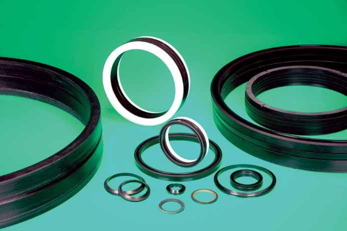
49 Portfolio To order or for further details, call your local contact 49 shown on rear cover or listed at 49
50 Chemical compatibility chart KEY: 1 = VERY GOOD 2 = GOOD 3 = POOR 4 = CONSULT JAMES WALKER X = NO DATA Acrylic (ACM) Aflas (FEPM) Butyl (IIR) Chlorosulphonyl polyethylene (CSM) RUBBER Elast-O- Lion (HNBR) Epichlorohydrin (ECO) Ethylene propylene (EPM/ EPDM) Fluoroelastomers (FKM) *G Fluorosilicone (FVMQ) Kalrez (FFKM) Air & oxygen Water <80 C Water >80 C 3 1*F Salt water Acids: dilute, cold Alkalis: dilute Methanol *C Acetaldehyde (consult JW for other aldehydes) *C Ethylene diamine *C Other amines X Chlorinated solvents Ethers *C Ketones *C Hydrocarbons: aliphatic Hydrocarbons: aromatic Petrol/gasoline: leaded Kerosene Animal oil & fat Fuel oil & diesel Lubricating oil: mineral Lubricating oil: synthetic Silicone oil & grease Vegetable oil Hydraulic fluids: mineral HYDRAULIC FLUIDS: Fire resistant Chlorinated: HFD-S Oil in water emulsions: HFA Water in oil emulsions: HFB Water/glycol based: HFC Phosphate esters: HFD-R TEMPERATURE RANGE: C ( F) Minimum -20(-4) +5(+41) -35(-31) -30(-22) -29(-20)*A -30(-22) -45(-49) -18(0)*D -60(-76) -25(-13) -50(-58) Maximum: constant Maximum: intermittent +150 (+302) +175 (+347) +205 (+401) +230 (+446)*F +120 (+248) +150 (+302) +120 (+248) +150 (+302) +160 (+320) +200 (+392) +150 (+302) +175 (+347) +120 (+248) +150 (+302)*B +200 (+392) +230 (+446)*D +175 (+347) +200 (+392) +325 (+617) HARDNESS RANGE: IRHD Notes: *A Low acrylonitrile content grades are available for temperatures down to -55 C (-67 F). *B EPM grades are available for hot water service up to +180 C (+356 F). *C Fluoroelastomer grades are available which offer resistance to these chemicals. *D Fluoroelastomer grades are available for temperatures from -41 C to +250 C (-42 F to +482 F). *E Polyurethane grades are also available from Shore D hardness. *F Aflas grades are suitable for temperatures up to +260 C (+500 F) in hot water and steam. *G Viton grades are available on request. *H Delrin is available on request. Consult Natural rubber (NR) +100 (+212) +120 (+248) 50 To order or for further details, call your local contact shown on rear cover or listed at
51 Chemical compatibility chart Neoprene/ Chloroprene (CR) Nitrile (NBR) RUBBER Polyurethane (AU/EU) Silicone (VMQ) Virgin KEY: 1 = VERY GOOD 2 = GOOD 3 = POOR 4 = CONSULT JAMES WALKER X = NO DATA Glass loaded Fluolion (PTFE) Bronze loaded Carbon loaded THERMOPLASTICS Fluolion Xtreme Nylon 6 Acetal *H UHMWPE Polyether -ether ketone (PEEK ) X X 1-40(-40) -25(-13)*A -15(+5) -65(-85) -200(-328) Consult Consult Consult Consult Consult Consult Consult Consult +120 (+248) +150 (+302) +110 (+230) +150 (+302) +85 (+185) +100 (+212) +200 (+392) +250 (+482) +250 (+482) Consult Consult Consult Consult Consult Consult Consult Consult Consult Consult Consult Consult Consult Consult Consult Consult Consult *E Consult Consult Consult Consult Consult Consult Consult Consult Consult WARNING: Please note that, due to the complexity of making a material selection for any given duty, all information provided in this document on chemical compatibility is intended only as a guide. For example, a compound compatible at low temperatures may show considerable deterioration at high temperatures; also, combinations of chemicals in a fluid medium may have detrimental effects. Actual service life will depend on type of application, whether static or dynamic, specific pressure medium, temperature cycle, time of exposure, etc. The low temperatures quoted are generally values at atmospheric pressure and may change at elevated pressures. If any doubt exists, please seek advice from James Walker. To order or for further details, call your local contact 51 shown on rear cover or listed at 51
52 Machining information The recommendations in this section for limits, fits and surface finishes are intended as a general guide when manufacturing and reconditioning equipment. These are the requirements for good seal performance, but we acknowledge that in many cases acceptable results will be obtained with values outside those stated. The housing envelope sizes for the seals listed in this document can be obtained from the individual product sections. However, more general considerations such as tolerances, fits, extrusion clearances and surface finish requirements for optimum seal performance are common to the majority of seal types. Thus the following information, most of which is based on BS ISO 5597 Housings for piston and rod seals in reciprocating applications: Dimensions and tolerances, will form a good basis for housing design in the majority of cases. If in doubt, or severe operating conditions apply, please contact our Technical Support Team for recommendations. Guide bush details The positioning of guide bushes on the pressure side of the gland housing ensures their correct lubrication. Close fitting bushes are desirable to protect the rod or gland seals from the action of eccentric rods. Close fitting bushes, however, can cause fluid starvation to the seal housing; or in certain conditions, an intensification of fluid pressure can occur. These potential hazards can easily be avoided by providing pressure relief through the bush to the adjacent seal housing. Rod/ram hardness Our hydraulic seals tolerate many levels of counterface hardness, but for optimum life particularly at higher pressures we recommend a minimum of 300 Brinell (31 Rockwell C). Extrusion clearance Extrusion clearance The control of extrusion clearances between the gland follower and rod is of vital importance. The gap between the rod and the inside of gland follower must be as small as possible, but should not be smaller than guidance fit allows. This is achieved by ensuring a very close fit between the outside of the gland follower and the housing bore. The fit between adjacent housing components should be kept to a minimum. See table above for extrusion clearances for an H9/f8 guidance fit at neck bush where arduous conditions apply. An equivalent level of fit between piston head and cylinder bore is also recommended. Recommended extrusion clearances: mm (inch) Shaft Ø f8 * 1 ; Cylinder Ø H9 * Diametral tolerances Maximum diametral 1 extrusion clearance: E Above Up to and including Shaft / Gland applications Follower bore (Inside) Ø * 2 Piston / Cylinder applications Piston (outside) Ø * 3 - * MPa ( psi) MPa ( psi) / N/A (0.39) (0.71) ( / ) (0.008) (0.006) / / (0.71) (1.18) ( / ) ( / ) (0.009) (0.006) / / (1.18) (1.97) ( / ) ( / ) (0.012) (0.008) / / (1.97) (3.15) ( / ) ( / ) (0.014) (0.009) / / (3.15) (4.72) ( / ) ( / ) (0.019) (0.013) / / (4.72) (7.09) ( / ) ( / ) (0.021) (0.014) / / (7.09) (8.84) ( / ) ( / ) (0.022) ( / / (8.84) (12.40) ( / ) ( / ) (0.024) (0.016) / / (12.40) (15.75) ( / ) ( / ) (0.028) (0.018) / / (15.75) (19.69) ( / ) ( / ) (0.030) (0.020) Notes * 1 Tolerances based on BS EN ISO and BS EN ISO * 2 Tolerances based on BS EN ISO and BS EN ISO 286-2, using plus H9 maximum as the minimum follower bore Ø and then plus another H9 maximum to provide the maximum follower bore Ø. * 3 Tolerances based on BS EN ISO and BS EN ISO 286-2, using minus H9 maximum as the maximum follower outside Ø and then minus another H9 maximum to provide the minimum follower outside Ø. * 4 When using these clearance tolerances careful consideration must be given the effects of cylinder dilation due to pressure fluctuations. Maximum diametral extrusion clearance E. Shaft/follower bore and cylinder bore/piston at maximum eccentricity (touching). Radial extrusion clearance E/2. Shaft/follower bore and cylinder bore/piston concentric. E/2 E 52 To order or for further details, call your local contact shown on rear cover or listed at
53 Machining information Surface roughness values for piston & rod housings Please note that the statements and surface roughness values shown are based generally on BS ISO 5597 Dynamic and static surfaces The surface roughness of the housing surfaces in contact with our sealing products, both dynamic and static, has a significant impact on the life and performance of these products. The roughness values of surfaces in contact with James Walker's hydraulic seals and associated products should normally be in accordance with those shown in the Surface roughness table (right). The exceptions are: 1) When specific roughness values are quoted for a particular product, such as Lionsele LF (see Appendix D, page 57). 2) When specific roughness values outside those stated have been negotiated and agreed between an equipment manufacturer and James Walker. Please note that exceptional service conditions can also necessitate the selection of other grades of surface roughness. In such cases, please consult our Technical Support Team. It is important to ensure that all surfaces against which a James Walker product operates particularly a hydraulic seal should be free from chatter marks and scores along the operating axis of the seal. Surface roughness table Table notes: 1) PTFE seals will operate on both static and dynamic surfaces with roughness values of 0.1µm Ra or better. This, however, should be avoided as longer term operation, particularly on dynamic surfaces, could be impaired. 2) Indication of surface roughness taken from ISO ) Visual surface imperfections are not allowed on surfaces B and C (see ISO 8785). 4) See ISO for design of edges and undefined shapes. Where surface roughness measurements are taken, it is recommended that instruments complying with ISO 3274, including an electric wave filter, be used. Rubber-proofed fabrics Rubbers Polyurethanes Seal contact material PTFE (eg, James Walker Fluolion ) Groove contact surface Contact surface roughness values: µm Ra Side surfaces: A 2) Static pressure mating surfaces: B 3) ) 0.25 Dynamic pressure mating surfaces: C 3) Lead-in/lead-on chamfer surfaces: D 4) 0.4 visual inspection B C A A A B B Chamfer surfaces See Detail 'A' Wiper groove O/D surface Rod/shaft Seal groove side surfaces Wiper groove side surfaces Bearing groove side surfaces Detail 'A' Lead -in/on chamfer surfaces D Seal groove I/D ; O/D surfaces Bearing groove I/D ; O/Dsurfaces C Bore/cylinder To order or for further details, call your local contact 53 shown on rear cover or listed at 53
54 Header Appendix A Chevron preferred housing designs Design dimensional nomenclature Chevron preferred housing dimensions Appendix A Shaft/gland housing arrangement Nominal groove O/D : d1 ((Chevron 015 Ø : d diagram)) ; H9** Piston/cylinder housing arrangement ((Chevron Nominal 014 diagram)) groove Cylinder Ø : D ; H9** Radius : R Max Groove radial depth : S Guidance fit Radius : R Max Groove radial depth : S I/D : D1 Guidance fit Ø : D ; f8** Groove axial length : L E/2 *** Groove axial length : L E/2 *** Guidance fit Ø : D1 ; H9** Guidance fit Ø : d1 ; f8** Edges to be rounded and burr free ; Max radius /30 Chamfer axial length : C Min 20/30 Shaft Ø : d ; f8** Edges to be rounded and burr free ; Max radius /30 Chamfer axial length : C Min 20/30 Chamfer axial length : C Min Shaft Ø; d; f8 1) Cylinder Ø; D; H9 1) Housing Above Up to & including Above Up to & including Metric sizes (mm) Radial depth S N/A N/A , > > Inch sizes (inch) > 11/16 > 1 1/16 3/16 1/2 11/ /16 1 1/2 1/4 3/ /2 2 5/8 5/ /2 2 5/8 4 1/4 3/8 1 1/4 3 1/ /4 7 1/2 1 3/ /4 5/ /4 25 1/2 2 7/8 3/ /2 37 1/2 3 1/4 Axial length L Nominal Tolerance > 37 1/2 > 1 3 3/4 1) Tolerances in accordance with BS EN ISO & BS EN ISO Notes 1) For existing applications, please first check our Hydraulic sealing products Size charts (see page 83). 2) For new applications housing dimensions are to be based on BS ISO 5597 Long (L3) axial length series housings: See Appendix W. 3) E/2 ***: Radial clearances and extrusion gaps (parts concentric): See Machining information section. 4) Surface roughness and finish requirements: See Machining information section. 5) ** Tolerances in accordance with BS EN ISO and BS EN ISO 286-2: See Appendix V. 54 To order or for further details, call your local contact 54 shown on rear cover or listed at
55 Appendix Header B Solosele G preferred housing designs Design dimensional nomenclature Solosele G preferred housing dimensions Shaft/gland housing arrangement Radius : R Max Nominal groove O/D : d1 Groove radial depth : S Guidance fit ((Chevron 015 Ø : d diagram)) ; H9** Piston/cylinder housing arrangement Radius : R Max Groove radial depth : S Nominal groove I/D : D1 Cylinder Guidance fit Ø : D ; H9** Ø : D ; f8** Groove axial length : L E/2 *** Groove axial length : L E/2 *** Guidance fit Ø : D1 ; H9** Guidance fit Ø : d1 ; f8** Edges to be rounded and burr free ; Max radius /30 Chamfer axial length : C Min 20/30 Shaft Ø : d ; f8** Edges to be rounded and burr free ; Max radius /30 Chamfer axial length : C Min 20/30 Chamfer axial length : C Min Shaft Ø; d; f8 1) Cylinder Ø; D; H9 1) Housing Above Up to & including Above Up to & including Metric sizes (mm) Radial depth S > > Inch sizes (inch) 1/4 1 5/8 1 3/8 3/16 1/ /8 2 1/2 1/4 5/ /2 2 1/2 4 1/8 5/16 3/8 3 1/2 5 1/2 4 1/8 6 1/4 3/8 15/32 5 1/ /4 9 1/2 5/ /4 5/8 25/ /4 15 1/2 3/ > 15 1/2 > 1 1 1/4 Axial length L Nominal Tolerance ) Tolerances in accordance with BS EN ISO & BS EN ISO Appendix B Notes 1) For existing applications, please first check our Hydraulic sealing products Size charts (see page 83). 2) For new applications housing dimensions are to be based on BS ISO 5597 Short (L1) and Medium (L2) axial length series housings: See Appendix W. 3) E/2 ***: Radial clearances and extrusion gaps (parts concentric): See Machining information section. 4) Surface roughness and finish requirements: See Machining information section. 5) ** Tolerances in accordance with BS EN ISO and BS EN ISO 286-2: See Appendix V. To order or for further details, call your local contact 55 shown on rear cover or listed at 55
56 Header Appendix C Twinset preferred housing designs Design dimensional nomenclature Appendix C Shaft/gland housing arrangement Radius : R Max Groove axial length : L Edges to be rounded and burr free ; Max radius 0.50 Piston/cylinder housing arrangement Radius : R Max Groove axial length : L E/2 *** Edges to be rounded and burr free ; Max radius /30 Nominal groove O/D : d1 Groove radial depth : S Guidance fit Ø : d ; H9** E/2 *** Guidance fit Ø : d1 ; f8** 20/30 Chamfer axial length : C Min 20/30 Shaft Ø : d ; f8** Groove radial depth : S Nominal groove I/D : D1 Cylinder Guidance fit Ø : D ; H9** Ø : D ; f8** Guidance fit Ø : D1 ; H9** 20/30 Chamfer axial length : C Min Chamfer axial length : C Min Notes 1) For existing applications, please first check our Hydraulic sealing products Size charts (see page 83). 2) For new applications housing dimensions are to be based on BS ISO 5597 Long (L3) axial length series housings: See Appendix W. 3) E/2 ***: Radial clearances and extrusion gaps (parts concentric): See Machining information section. 4) Surface roughness and finish requirements: See Machining information section. 5) ** Tolerances in accordance with BS EN ISO and BS EN ISO 286-2: See Appendix V. Twinset preferred housing dimensions Shaft Ø; d; f8 1) Cylinder Ø; D; H9 1) Housing Above Up to & including Above Up to & including Radial depth S Metric sizes (mm) > > Axial length L Nominal Tolerance Minimum chamfer length C Min , Groove base rad R Max , > > Inch sizes (inch) > 1 1/16 > 1 1/8 3/16 7/ / /8 1 1/2 1/4 9/ /2 2 5/8 5/16 3/ , /2 2 5/8 4 1/4 3/8 15/ / /4 7 1/2 1 1/ /4 5/8 1 1/ /4 20 3/4 1 3/ /4 37 1/ , 36 > 37 1/2 > ) Tolerances in accordance with BS EN ISO and BS EN ISO To order or for further details, call your local contact shown on rear cover or listed at
57 Appendix Header D Lionsele LF preferred housing designs Design dimensional nomenclature Shaft/gland housing arrangement Sharp edge/corner to be removed whilst maintaining maximum possible support against extrusion Groove base radius : R max Maximum radial extrusion clearance : E/2 (Rod, housing and follower concentric) 20/30 Groove radial depth : S Piston/cylinder housing arrangement Maximum radial extrusion clearance : E/2 (Piston and bore concentric) Groove radial depth : S Sharp edge/corner to be removed whilst maintaining maximum possible support against extrusion Edges to be rounded and burr free Chamfer axial length : C Min 20 / 30 Appendix D Chamfer axial length : C Min Groove base radius : R max Guidance fit Ø d1 : f8** Guidance fit Ø d : H9** Groove axial length : L 20/30 Edges to be rounded and burr free Shaft Ø : d ; f8** Nominal groove O/D : d1 Nominal groove I/D : D1 20 / 30 Chamfer axial length : C Min Guidance fit Ø D1 : H9** Groove axial length : L Retainer Ø : D2 h11 ** Cylinder bore Ø : D H9 ** Notes 1) For existing and new applications see JW preferred housing dimensions. 2) E/2**; Radial clearances and extrusion gaps (parts concentric): see Preferred housing dimensions. 3) For all surface roughness and finish values, dynamic and static, see Surface finish requirements at bottom of page. 4) ** Tolerances in accordance with BS EN ISO and BS EN ISO Lionsele LF preferred housing dimensions Cylinder/piston housings (mm) Cylinder Ø D H9 ** Above Up to Retainer Ø D2 h11 ** Radial depth S Housing groove Maximum extrusion gap E Chamfer Axial length Base radius length L Rmax MPa MPa C Min 1.52 / / / / D1 = / / (ØD -1.5 x S) / / / / Rod/shaft gland housings (mm) Rod Ø f8 d ** Housing groove Maximum extrusion gap E Chamfer Above Up to Radial depth S Axial length Base radius length L Rmax MPa MPa C Min / / / / / / / / / / ** Tolerances in accordance with BS EN ISO and BS EN ISO Surface finish requirements The recommended values for surface finish are as shown below. Surface finish values better than 0.1µm Ra should not be used. Application Surface finish - BS 1134 : Part 1 All cryogenics. Dynamic duties with light gases (H, He, etc) Static duties with light gases (H, He, etc). Dynamic duties with other media Static duties with other gases. Static duties with gasoline, diesel and aviation fuels General static duties - Water and aqueous solutions, hydraulic fluids, oils and other liquids 0.1 to 0.2 µm (4 to 8 µin) Ra 0.1 to 0.3 µm (4 to 12 µin) Ra 0.1 to 0.8 µm (4 to 32 µin) Ra 0.1 to 1.6 µm (4 to 64 µin) Ra To order or for further details, call your local contact 57 shown on rear cover or listed at 57
58 Header Appendix E Lionsele U1, U2 & U3 preferred housing designs Design dimensional nomenclature Appendix E Lionsele U1 and U2 shaft/gland housing arrangement Radius : R Max Groove axial length : L Edges to be rounded and burr free ; Max radius /30 Groove radial depth : S E/2 *** Chamfer axial length : C Min Nominal groove O/D : d1 20/30 Guidance fit Ø : d ; H9** Guidance fit Ø : d1 ; f8** Shaft Ø : d ; f8** Lionsele U1 and U3 piston/cylinder housing arrangement Radius : R Max Groove radial depth : S Groove axial length : L E/2 *** Edges to be rounded and burr free ; Max radius /30 Chamfer axial length : C Min Cylinder Ø : D ; H9** Nominal groove I/D : D1 Guidance fit Ø : D ; f8** Guidance fit Ø : D1 ; H9** 20/30 Chamfer axial length : C Min Notes 1) For existing and new applications housing dimensions are to be based on BS ISO 5597 Short (L1) and Medium (L2) axial length series, and BS ISO housings. See Appendix W. 2) E/2 ***: Radial clearances and extrusion gaps (parts concentric): See Machining information section. 3) Surface roughness and finish requirements: See Machining information section. 4) ** Tolerances in accordance with BS EN ISO and BS EN ISO 286-2: See Appendix V. 58 To order or for further details, call your local contact 58 shown on rear cover or listed at
59 Appendix Header F Lofilm preferred housing designs Design dimensional nomenclature Shaft/gland housing arrangement Radius : R Max Groove axial length : L Edges to be rounded and burr free ; Max radius 0.50 Appendix F 20/30 Nominal groove O/D : d1 Groove radial depth : S Guidance fit Ø : d ; H9** E/2 *** Guidance fit Ø : d1 ; f8** Chamfer axial length : C Min 20/30 Shaft Ø : d ; f8** Notes 1) For existing applications, please first check our Hydraulic sealing products Size charts (see page 83). 2) For new applications housing dimensions are to be based on BS ISO 5597 Long (L3) axial length series housings: See Appendix W. 3) E/2 ***: Radial clearances and extrusion gaps (parts concentric): See Machining information section. 4) Surface roughness and finish requirements: See Machining information section. 5) ** Tolerances in accordance with BS EN ISO and BS EN ISO 286-2: See Appendix V. Lofilm preferred housing dimensions Above Shaft Ø; d; f8 1) Up-to and including Radial depth S Metric sizes (mm) Housing Nominal > Inch sizes (inch) > 11/16 3/16 1/2 11/16 1 1/4 3/ / /2 3/8 1 1/4 3 1/2 6 1/2 1 3/ / /8 3/ /4 36 > 1 3 3/4 1) Tolerances in accordance with BS EN ISO and BS EN ISO Axial length L Tolerance , , - 0 To order or for further details, call your local contact 59 shown on rear cover or listed at 59
60 Header Appendix G Lion Expanding preferred housing designs Header Design dimensional nomenclature Appendix G Shaft/gland housing arrangement Groove axial length : L Chamfer axial length : C Min Groove radial depth : S 20/30 20/30 Groove outside Ø : D1 (= d + 2s ; H10**) Guidance fit Ø d ; H10** Guidance fit Ø D1 ; f8** E/2 *** Chamfer axial length : C Min Shaft Ø : d ; f8** Notes 1) For existing and new applications see JW preferred housing dimensions. 2) E/2 ***: Radial extrusion clearance: See Machining information section. 3) Surface roughness and finish requirements: See Machining information section. 4) ** Tolerances in accordance with BS EN ISO and BS EN ISO 286-2: See Appendix V. Lion Expanding preferred housing dimensions Shaft Ø; d; e8** Nominal set / housing depth L Nominal radial depth Above Up to & including S Above 35 and Up to 35MPa up to 62MPa Metric sizes (mm) Chamfer length C Min Inch sizes (Inch) ** Tolerances in accordance with BS EN ISO and BS EN ISO To order or for further details, call your local contact 60 shown on rear cover or listed at 60
61 Header Appendix Header H Lofilm HD preferred housing designs Design dimensional nomenclature Shaft/gland housing arrangement Groove axial length : L Chamfer axial length : C Min Appendix H Groove radial depth : S 20/30 20/30 Groove outside Ø : D1 (= d + 2s ; H10**) Guidance fit Ø d ; H10** Guidance fit Ø D1 ; f8** E/2 *** Chamfer axial length : C Min Shaft Ø : d ; f8** Notes 1) For existing and new applications see JW preferred housing dimensions. 2) E/2 ***: Radial extrusion clearance: See Machining information section. 3) Surface roughness and finish requirements: See Machining information section. 4) ** Tolerances in accordance with BS EN ISO and BS EN ISO 286-2: See Appendix V. Lofilm HD preferred housing dimensions Above Shaft Ø; d; e8** Up to & including Nominal radial depth S Metric sizes (mm) Housing length L Chamfer length C Min Inch sizes (inch) ** Tolerances in accordance with BS EN ISO and BS EN ISO To order or for further details, call your local contact 61 shown on rear cover or listed at 61
62 Header Appendix I Lionsele G preferred housing designs Design dimensional nomenclature Appendix I Shaft/gland housing arrangement Sharp edges and corners to be removed whilst maintaining maximum possible support against extrusion Notes 1) For existing applications see JW preferred housing dimensions. 2) For new applications housing dimensions are to be based on BS ISO ; Tables 1 and 2. 3) E***: Radial clearances and extrusion gaps (parts concentric): See Machining Information section. 4) Surface roughness and finish requirements: See Machining information section. 5) ** Tolerances in accordance with BS EN ISO and BS EN ISO 286-2: See Appendix V. Lionsele G preferred housing dimensions Shaft Ø; d; f8** (mm) Above Rod / Shaft Ø : d f8 ** E*** Up to & including Groove axial length : L Housing groove (mm) Nominal radial depth S Groove base radius : R max Chamfer axial length : C Min Nominal axial length L / +0 Groove radial depth : S 20/30 Groove outside Ø : d1 Chamfer length C min (mm) > ** Tolerances in accordance with BS EN ISO and BS EN ISO Dimensions and tolerances for rod seal housings Based on BS ISO Tables 1 and 2 Rod 1) Ø; d; f8 2) (mm) Outside Ø d Groove dimensions (mm) Tolerance Nominal radial depth S Axial length L / Base radius Rmax Chamfer length C Min (mm) H9 ** H8 ** ) Bore diameters in accordance with ISO ) See BS EN ISO and BS EN ISO To order or for further details, call your local contact 62 shown on rear cover or listed at
63 Appendix Header J Lionsele SP preferred housing designs Design dimensional nomenclature Piston housing arrangement Overall housing length : L3 (Ref only) L1 L2 Chamfer length C Min Appendix J Cylinder Ø D H9 Piston Ø D3 ; h11 Bearing seat Ø D2 ; h9 E*** Rad : R Piston head * Rounded and burr free 20 / 30 Nominal radial depth S Seal groove Ø D1 ; h9 Notes 1) For existing and new applications housing dimensions are to be based on BS ISO ) Piston head * ; Design can be multicomponent assembly as shown or single component. 3) E *** ; Radial clearances and extrusion gaps (Parts concentric): See Machining Information Section. 4) Surface roughness and finish requirements: See Machining information section. 5) ** Tolerances in accordance with BS EN ISO and BS EN ISO Lionsele SP piston seal housing dimensions Based on BS ISO 6547 Cylinder Ø D 2 H9 2 ** Housing diameters (mm) Seal groove Ø D1 h9 ** Bearing ring Ø D2 h9 ** Piston Ø D3 h11 ** Nominal radial section S (mm) Seal groove length L / Axial lengths (mm) Bearing ring length L /+0 Overall length (Ref only) L3 Base radius Rmax (mm) Chamfer length C Min (mm) ) See ISO ) Tolerance H11 on bore diameter may be used except when using smaller radial section seals for diameters of 25 to 160 mm inclusive To order or for further details, call your local contact 63 shown on rear cover or listed at 63
64 Header Appendix K Lionsele P preferred housing designs Design dimensional nomenclature Appendix K Piston housing arrangement Groove axial length : L Chamfer axial length : C Min E *** 20/30 Groove radial depth : S Groove inside Ø : D1 h9** Groove base radius : R max Sharp edges and corners to be removed whilst maintaining maximum possible support against extrusion Cylinder Ø : D H9** Notes 1) For existing applications, please first check our Hydraulic sealing products Size charts (see page 83). 2) For new applications housing dimensions are to be based on BS ISO ; Tables 1 and 2. 3) E***: Radial clearances and extrusion gaps (parts concentric): See Machining Information section. 4) Surface roughness and finish requirements: See Machining Information section. 5) ** Tolerances in accordance with BS EN ISO and BS EN ISO 286-2: See Appendix V. Lionsele P preferred housing dimensions and tolerances Based on BS ISO Tables 1 and 2 Cylinder Ø H9** (mm) Housing groove (mm) Chamfer length Above Up to and including Radial depth (Section) S Nominal Axial length L C Min / + 0 (mm) > ** Tolerances in accordance with BS EN ISO and BS EN ISO To order or for further details, call your local contact shown on rear cover or listed at
65 Appendix K Lionsele P preferred housing designs Lionsele P piston seal housings dimensions and tolerances Based on BS ISO Tables 1 and 2 Bore Ø 1) D H9 ** (mm) Radial depth S (mm) Groove Ø d h9 ** (mm) Groove axial length - L (mm) / 2.40 Base radius Rmax (mm) 0.50 Chamfer length C Min (mm) / / / / / / / / / / / / / / / / / / / / / / / / / / / / / / / / / / / / / / / / / / / / / Appendix K 1) Bore diameters in accordance with ISO 3320 ** All tolerances in accordance with BS EN ISO and BS EN ISO To order or for further details, call your local contact 65 shown on rear cover or listed at 65
66 Header Appendix L Solosele S preferred housing designs Header Design dimensional nomenclature Appendix L Piston housing arrangement Groove axial length : L Edges to be rounded and burr free ; Max radius 0.50 Radius : R Max E/2 *** 20/30 Groove radial depth : S Chamfer axial length : C Min Cylinder Ø : D ; H9** Nominal groove I/D : D1 Guidance fit Ø : D ; f8** Guidance fit Ø : D1 ; H9** 20/30 Chamfer axial length : C Min Notes 1) For existing and new applications housing dimensions are to be based on BS ISO 5597 Medium (L2) axial length series housings: See Appendix W. 2) E/2 ***: Radial clearances and extrusion gaps (parts concentric): See Machining information section. 3) Surface roughness and finish requirements: See Machining information section. 4) ** Tolerances in accordance with BS EN ISO and BS EN ISO 286-2: See Appendix V. 66 To order or for further details, call your local contact 66 shown on rear cover or listed at 66
67 Appendix Header M Solosele SW preferred housing designs Design dimensional nomenclature Shaft/gland housing arrangement Notes 1) Piston head* ; Design can be multicomponent assembly as shown or single component. 2) E*** ; Radial clearances and extrusion gaps (Parts concentric) : See Machining Information Section. 3) Surface roughness / finish requirements : See Machining Information Section. 4) **Tolerances in accordance with BS EN ISO and BS EN ISO Appendix M Solosele SW preferred housing dimensions Cylinder Ø D H9** Seal groove Inside Ø D1 h9** Housing diameters (mm) Bearing seat Ø D2 h10** Piston Ø D3 h11** Nominal radial depth S Seal seat L1 + 0, Groove dimensions (mm) Axial lengths Bearing seat L Overall (Ref) L Base radius Rmax Chamfer length C Min (mm) ** Tolerances in accordance with BS EN ISO and BS EN ISO To order or for further details, call your local contact 67 shown on rear cover or listed at 67
68 Header Appendix N Composite seals (special duty) preferred housing designs Design dimensional nomenclature Appendix N Housing arrangement Radius 0.25 Max Cylinder / Piston Ø : D Tolerances ** Cylinder - H9 ; Piston - e9 Sharp edges and corners to be removed whilst maintaining maximum possible support against extrusion Guidance fit Ø D1 : H9 Groove inside Ø D1 Groove axial length : L A ## Edges to be rounded and burr free Chamfer axial length : C Min A ## 20/30 A ## Chamfer B ### Piston Notes 1) For existing and new applications see JW preferred housing dimensions. 2) A ## Chamfer: Details typical for all chamfers when used. 3) B ### Piston: Design can be multicomponent assembly as shown or single machined component. 4) Surface roughness and finish requirements: See Machining information section. 5 ** Tolerances in accordance with BS EN ISO and BS EN ISO 286-2: See Appendix V. Composite seals preferred housing dimensions (Standard seal range) Cylinder Ø D H9** Housing dimensions Groove Ø D1 Axial length L Chamfer length C Min Metric sizes (mm) / / / / / / / / / / / / / / / / / Inch sizes (in) 3/ / / / / / / / / / / / / / / / / / / / / / / / / / / / / / / / / / / / / / Composite seals preferred housing dimensions (Non-standard seals) Cylinder Ø d H9** Housing dimensions Chamfer Above Up to & length Radial depth S Axial length L Inc. C Min Metric sizes (mm) / / / / / / / / / / / / Inch sizes (in) - 7/ / / / / / / / / / / / / / ** Tolerances in accordance with BS EN ISO & BS EN ISO To order or for further details, call your local contact shown on rear cover or listed at
69 Appendix Header O Lionsele W1 wiper preferred housing designs Design dimensional nomenclature Housing arrangement Radius : R1-2 positions Groove radial depth : S Radius : R2-2 positions Retainer can be integral or a separate component Edges to be rounded and burr free Appendix O Groove outside Ø : d1 - H11 ** Rod Ø : d - f8 ** Groove axial length : L1 Wiper overall axial length : L / /30 Chamfer axial length : C Min Lionsele W1 housing dimensions for Type A wiper Based on BS ISO 6195 Tables 1 and 7 Retaining lip inside Ø : d2 - H11 ** Notes 1) For existing and new applications housing dimensions are to be based on BS ISO 6195, Type A. 2) Surface roughness and finish requirements: See Machining information section. 3) ** Tolerances in accordance with BS EN ISO and BS EN ISO 286-2: See Appendix V. Rod Ø (mm) A), B) Radial depth (mm) Outside Ø (mm) Axial length (mm) Retainer Ø (mm) Radii Max (mm) Wiper length (mm) Chamfer length (mm) d S Ø d1 H11** L1 Ø d2 H11** R1 R2 C) L2 Max C Min ; ; ; ; A) See ISO 3320 and BS ISO 5597 B) One-piece housings can be used with rod diameters greater than 14mm C) These specific dimensions permit the use of tools conforming to ISO 883 / BS To order or for further details, call your local contact 69 shown on rear cover or listed at 69
70 Header Appendix P Lionsele W2 wiper preferred housing designs Appendix P Design dimensional nomenclature Housing arrangement Radius : R 0.9 Groove radial depth : S 20/30 Edges to be rounded and burr free Groove outside Ø : d1 - H8 ** Rod Ø : d - f8 ** Groove axial length : L / /30 Chamfer axial length : C Min Notes 1) For existing and new applications housing dimensions are to be based on BS ISO 6195, Type B. 2) Surface roughness and finish requirements: See Machining information section. 3) ** Tolerances in accordance with BS EN ISO and BS EN ISO 286-2: See Appendix V. Lionsele W2 housing dimensions for Type B wiper Based on BS ISO 6195 Tables 2 and 7 Rod Ø A) (mm) Radial depth (mm) Outside Ø (mm) Axial length (mm) Wiper length (mm) Chamfer length (mm) d f8** S Ø d1 H8** L ; - 0 L2 Max C Min A) See ISO 3320 and BS ISO 5597 ** All tolerances in accordance with BS EN ISO and BS EN ISO To order or for further details, call your local contact 70 shown on rear cover or listed at
71 Appendix Header Q Lionsele W3 wiper preferred housing designs Design dimensional nomenclature Housing arrangement Groove radial depth : S R 0.50, Typical 2 positions R1 Max Retainer can be integral or a separate component R 0.50 / 1.00 Edges to be rounded and burr free Appendix Q Groove outside Ø : d1 - H11 ** Rod Ø : d - f8 ** Groove axial length : L1 Wiper overall axial length : L2 Max 2.00 / /30 Chamfer axial length : C Min Lionsele W3 housing dimensions for Type C wiper Based on BS ISO 6195 Tables 3 and 7 Retaining lip inside Ø : d2 - H11 ** Rod Ø A), B) (mm) Radial depth Outside Ø Axial length Wiper length Retainer Ø Radius Chamfer length (mm) (mm) (mm) (mm) (mm) (mm) (mm) d f8** S Ø d1 H11** L1 L2 Max Ø d2 H11** R1 Max C Min C) C) C) C) C) C) C) C) C) C) C) C) D) D) D) D) D) A) See ISO 3320 and BS ISO 5597 B) Split housings should be used for rod diameters up to and including 18mm C) These sizes are recommended for use with cylinders conforming to BS ISO and BS ISO D) These sizes are recommended for use with cylinders conforming to BS ISO ** All tolerances in accordance with BS EN ISO and BS EN ISO Notes 1) For existing and new applications housing dimensions are to be based on BS ISO 6195, Type C. 2) Surface roughness and finish requirements: See Machining information section. 3) ** Tolerances in accordance with BS EN ISO and BS EN ISO 286-2: See Appendix V. 71 To order or for further details, call your local contact 71 shown on rear cover or listed at 71
72 Header Appendix R Header Wyclip scraper/wiper preferred housing designs Appendix R Design dimensional nomenclature Housing arrangement Radii (inch) 0.50 (mm) Max 2 positions Groove radial depth : S Edge and corner to be kept sharp and clean Radius (inch) / 1.50 (mm) Max 20/30 Groove outside Ø : d / + 0 (inch) / +0 (mm) Rod Ø : d f8 ** Groove axial length : L / + 0 (inch) / + 0 (mm) Housing overall axial length : L / + 0 (inch) / + 0 (mm) Chamfer axial length : C Min Retaining lip inside Ø : d / + 0 (inch) / + 0 (mm) Wyclip preferred housing dimensions JW Chart 62 Inch sizes (inch) Shaft Ø - d f8 ** Housing groove O/D - d1 Retaining lip Ø - d2 1/4 5/8 9/16 3/8 3/4 11/16 1/2 7/8 13/16 5/8 1 15/16 3/4 1 1/4 1 3/16 7/8 1 3/8 1 5/ /2 1 7/16 1 1/8 1 5/8 1 9/16 1 1/5 1 2/3 1 5/8 1 1/4 1 3/4 1 11/16 1 3/8 1 7/8 1 13/16 1 1/ /16 1 5/8 2 1/8 2 1/16 1 3/4 2 1/4 2 3/ /2 2 7/16 2 1/4 2 3/4 2 11/16 2 3/8 2 7/8 2 13/16 2 1/ /16 2 5/8 3 1/8 3 1/16 2 3/4 3 1/4 3 3/ /2 3 7/16 3 1/4 3 3/4 3 11/16 3 3/8 3 7/8 3 13/16 3 1/ /16 3 3/4 4 1/4 4 3/ /2 4 7/16 4 3/8 4 7/8 4 13/16 4 1/ /16 4 3/4 5 1/4 5 3/16 4 7/8 5 3/8 5 5/ /2 5 7/16 5 1/2 6 1/8 6 1/ /8 6 9/16 6 1/2 7 1/8 7 1/ /8 7 9/16 Nominal radial depth - S Housing groove axial length - L1 Overall housing axial length - L2 Chamfer axial length - C Min 3/16 11/64 1/4 1/16 1/4 15/64 11/32 3/32 5/16 1/8 ** Tolerances in accordance with BS EN ISO & BS EN ISO Notes 1) For all applications housing dimensions are to be in accordance with JW preferred housing dimensions. 2) Surface roughness and finish requirements: See Machining information section. 3) ** Tolerances in accordance with BS EN ISO and BS EN ISO 286-2: See Appendix V. Wyclip preferred housing dimensions JW Chart 67 Metric sizes (mm) Shaft Ø - d f8 ** Housing groove O/D - d1 Retaining lip Ø - d2 Nominal radial depth - S Housing groove axial length - L1 Overall housing length - L2 Chamfer axial length - C Min ** Tolerances in accordance with BS EN ISO & BS EN ISO To order or for further details, call your local contact 72 shown on rear cover or listed at 72
73 Appendix Y Appendix Header S Wyclip scraper/wiper Wiper preferred Type L preferred housing housing designs designs Design dimensional nomenclature Housing arrangement Rad. 0.5 Max 3 or 4 positions Dependent on Wiper retention design Groove outside Ø : d1 E9 ** Groove nominal radial depth : S Rod Ø : d f8 ** Groove axial length : L / + 0 Retainer can be integral or a separate component Rad. 1.5 Max 20/30 Housing overall axial length : L / Chamfer axial length : C Min Retaining lip inside Ø : d2 E9 ** Notes 1) All applications are to be in accordance with JW preferred housing dimensions. 2) Surface roughness and finish requirements: See Machining information section. 3) ** Tolerances in accordance with BS EN ISO and BS EN ISO 286-2: See Appendix V. Wiper Type L (JW Chart 524) preferred housing dimensions Metric sizes (mm) Shaft Ø d f8 ** Housing groove O/D d1 E9 ** Retainer lip Ø d2 E9 ** Nominal radial depth - S Overall housing length - L1 Housing groove axial length - L2 Chamfer axial length - C Min ** Tolerances in accordance with BS EN ISO & BS EN ISO Continued... Appendix S To order or for further details, call your local contact 73 shown on rear cover or listed at 73
74 Header Appendix S Wiper Type L preferred housing designs Appendix S Wiper Type L (JW Chart 525) preferred housing dimensions Metric sizes (mm) Shaft Ø d f8 ** Housing groove O/D d1 E9 ** Retainer lip Ø d2 E9 ** Nominal radial depth - S Overall housing length - L1 Housing groove axial length - L2 Chamfer axial length - C Min Wiper Type L (JW Chart 526) preferred housing dimensions Metric sizes (mm) Shaft Ø d f8 ** Housing groove O/D d1 E9 ** Retainer lip Ø d2 E9 ** Nominal radial depth - S Overall housing length - L1 Housing groove axial length - L2 Chamfer axial length - C Min ** Tolerances in accordance with BS EN ISO & BS EN ISO ** Tolerances in accordance with BS EN ISO & BS EN ISO To order or for further details, call your local contact shown on rear cover or listed at
75 Appendix T Lionsele B1 & B2 bearing Header strips preferred housing designs Design dimensional nomenclature Housing arrangement Housing radial depth - S Cylinder Ø - D Housing groove I/D - D1 Piston Ø - P Notes 1) ## Cylinder Ø - D and Rod Ø - d: Tolerances to be in accordance with individual seal requirements as detailed in the individual seal housing dimensional details. 2) ** Piston Ø - P and Gland Ø - G shall be determined by the individual seal requirements for radial clearances and extrusion gaps as detailed in the individual seal housing dimensional details. 3) Surface roughness and finish requirements: See Machining information section. Split arrangements T See Table Piston Arrangement Housing axial length - L 45 Rad 0.2 Max Rod Ø - d Shaft Arrangement Housing axial length - L Cylinder/rod Ø (mm) Up to 25 Gland Ø - G Lionsele B1 & B2 nominal housing dimensions Based on BS ISO Table 1 Axial length ; L Rad 0.4 Max Housing radial depth - S Housing groove O/D - d1 Gap T (mm) 2.0 Above 25 up to Above 50 up to Above 125 up to Above 250 up to Groove dimensions (mm) Radial depth ; S Housings for cut bearing rings for pistons/cylinders Based on BS ISO Table 2 Cylinder bore Ø - D ** (mm) I/D - D1 Housing groove dimensions (mm) Tolerance on D1 Axial length - L + 0 ; Radial depth - S Nominal ; ; Appendix T ** Tolerance usually no more than H10 (BS EN ISO & -2) and dependent on seal requirements for bore diameter tolerancing. Diametral Clearance: In piston applications this is the difference between the Cylinder bore Ø - D and Piston Ø - P and it controls the level of the extrusion gap (see Housing arrangement). It may be further increased by the expansion of the cylinder from internal pressure. The level of the extrusion gap is critical in achieving satisfactory and long term sealing performance; it should be the subject of consultations between the housing designer and James Walker. Continued... To order or for further details, call your local contact 75 shown on rear cover or listed at 75
76 Header Appendix AT Lionsele B1 & B2 bearing strips preferred housing designs Appendix T Housings for cut bearing rings for rods/shafts Based on BS ISO Table 3 Rod / Shaft Ø - d ; f8 ** (mm) O/D - d Housing groove dimensions (mm) Tolerance on d1 Axial length - L + 0 ; Radial depth - S Nominal ; ; Rod / Shaft Ø - d ; f8 ** (mm) O/D - d1 Housing groove dimensions (mm) Tolerance on d1 Axial length - L + 0 ; Radial depth - S Nominal ; ** All tolerances in accordance with BS EN ISO & BS EN ISO Diametrical Clearance: In piston applications this is the difference between the Rod Ø - d and Gland Inside Ø - G and it controls the level of the extrusion gap (see Housing arrangement). The level of the extrusion gap is critical in achieving satisfactory and long term sealing performance; it should be the subject of consultations between the housing designer and James Walker. 76 To order or for further details, call your local contact shown on rear cover or listed at
77 Appendix Header U Specifications & standards Reference BS 1134 BS /ISO 833 BS EN ISO Title Assessment of surface texture - Guidance and general information Hardmetal insert tooling. Specifications for dimensions of indexable hardmetal (carbide) inserts with rounded corners, without fixing hole ISO system of limits and fits - Part 1: Bases of tolerance and fits Appendix U BS EN ISO BS EN ISO 1302 BS EN ISO 3274 BS EN ISO 4287 BS EN ISO 4288 BS EN ISO 8785 BS EN ISO 885 BS ISO 5597 BS ISO BS ISO BS ISO BS ISO 6195 BS ISO 6547 BS ISO BS ISO BS ISO BS ISO ISO 883 ISO 3320 ISO ISO system of limits and fits - Part 2: Tables of standard tolerance grades and limit deviations for holes and shafts Geometrical Product Specifications (GPS) - Indication of surface texture in technical product documentation Geometrical Product Specifications (GPS) - Surface texture: Profile method - Nominal characteristics of contact (stylus) instruments Geometrical Product Specifications (GPS) - Profile method: Terms, definitions and surface texture parameters Geometrical Product Specifications (GPS) - Profile method: Rules and procedures for the assessment of surface texture Geometrical Product Specifications (GPS) - Surface imperfections - Terms, definitions and parameters General purpose bolts and screws - Metric sizes - Radii under the head Hydraulic Fluid Power - Cylinders. Dimensions and tolerances of housings for single-acting piston and rod seals in reciprocating applications Hydraulic Fluid Power - Mounting Dimensions for Single Rod Cylinders, 16 MPa (160 bar) series - Medium series Hydraulic Fluid Power - Mounting Dimensions for Single Rod Cylinders, 16 MPa (160 bar) series - Compact series Hydraulic Fluid Power - Mounting Dimensions for Single Rod Cylinders, 16 MPa (160 bar) series - Compact series with bores from 250mm to 500mm Fluid Power Systems and Components - Cylinder - Rod Wiper-Ring Housings in Reciprocationg Applications - Dimensions and Tolerances Hydraulic Fluid Power - Cylinders - Piston Seal Housings Incorporating Bearing Rings - Dimensions and Tolerances Hydraulic Fluid Power - Housings for elastomer-energized, plastic-faced seals - Dimensions and Tolerances - Part 1 : Piston Seal Housings Hydraulic Fluid Power - Housings for elastomer-energized, plastic-faced seals - Dimensions and Tolerances - Part 2 : Rod Seal Housings Hydraulic Fluid Power - Cylinders - Housing dimensions for rectangular-section-cut bearing rings for pistons and rods Technical drawings - Edges of undefined shapes - Vocabulary and indications See BS above Fluid power systems and components - Cylinder bores and piston rod diameters - Metric Series Hydraulic fluid power - Cylinder mounting dimensions - 10MPa (100bar) series To order or for further details, call your local contact 77 shown on rear cover or listed at 77
78 Header Appendix V Rod/shaft & tube/cylinder tolerances These tables are based on and extracted from BS EN ISO and BS EN ISO Appendix V Rod / shaft Ø (mm) Above Up to and including Lower limit Minus (-) Tolerances for rods / shafts (mm) e8 f8 h9 h10 h11 Upper limit Minus (-) Lower limit Minus (-) Upper limit Minus (-) Lower limit Minus (-) Upper limit Minus (-) Lower limit Minus (-) Upper limit Minus (-) Lower limit Minus (-) Upper limit Minus (-) Tube / cylinder Ø (mm) Tolerances for tubes / cylinders (mm) E8 H8 H9 H10 H11 Above Up to and including Lower limit Plus (+) Upper limit Plus (+) Lower limit Plus (+) Upper limit Plus (+) Lower limit Plus (+) Upper limit Plus (+) Lower limit Plus (+) Upper limit Plus (+) Lower limit Plus (+) Upper limit Plus (+) 78 To order or for further details, call your local contact shown on rear cover or listed at
79 Appendix Header W Piston seal housings Table 1 Based on BS ISO 5597 Tables 2,3 and 7 Nominal dimensions for piston seal housings (except where cylinders conform to BS ISO ; see Table 2) Notes: 1) Chevron & Lofilm : use housing axial length L3 Long only. 2) Solosele G, Lionsele U1 & U3: use housing axial lengths L1 Short and L2 Medium only. 3) Solosele S: use housing axial length L2 Medium only. Bore A Ø D H9 ** (mm) Nominal Radial depth S Actual Nominal inside Ø D1 Groove dimensions (mm) Axial length B L ; , - 0 L1 Short L2 Medium L3 Long Base radius R Max Chamfer length C Min (mm) / N/A / / N/A / / N/A / / / / / / / / / / / / / / / / / / / / / / See page 80 for BS ISO 5597 piston/cylinder housing nomenclature. A See ISO 3320 B The application of axial lengths in Table 1 (Short, Medium & Long) depends on respective working conditions ** All tolerances in accordance with BS EN ISO and BS EN ISO Appendix W To order or for further details, call your local contact 79 shown on rear cover or listed at 79
80 Header Appendix W Piston seal housings Table 2 based on BS ISO 5597 Tables 2, 4 and 7 Appendix W Nominal dimensions for piston seal housings for use where cylinders conform to BS ISO Note: Use with Solosele G, Lionsele U1 & U3 only. Bore A Ø D H9 ** (mm) Radial depth S Groove dimensions (mm) Nominal inside Ø D1 Axial length L , - 0 Base radius R Max B Chamfer length C Min (mm) A See ISO B This specific dimension permits the use of tools conforming to BS ISO 885 ** All tolerances in accordance with BS EN ISO and BS EN ISO Any relaxation of tolerances on one housing component will necessitate compensating tighter tolerances on another component to maintain the required radial seal space limits. Design dimensional nomenclature BS ISO 5597 piston/cylinder housing Radius : R Max Groove radial depth : S Groove axial length : L E/2 *** Edges to be rounded and burr free ; Max radius /30 Chamfer axial length : C Min Cylinder Ø : D ; H9** Nominal groove I/D : D1 Guidance fit Ø : D ; f8** Guidance fit Ø : D1 ; H9** 20/30 Chamfer axial length : C Min Notes 1) E/2 ***: Radial clearances and extrusion gaps (part concentric): See Machining information section. 2) Surface roughness and finish requirements: See Machining information section. 3) ** All tolerances in accordance with BS EN ISO and BS EN ISO To order or for further details, call your local contact 80 shown on rear cover or listed at
81 Appendix Header W Rod seal housings Table 3 Based on BS ISO 5597 Tables 2, 5 and 7 Nominal dimensions for rod seal housings (except where cylinders conform to BS ISO ; see Table 4) Notes: 1) Chevron & Lofilm : use housing axial length L3 Long only. 2) Solosele G, Lionsele U1 & U2: use housing axial length L1 Short and L2 Medium only. 3) Solosele S: use housing axial length L2 Medium only. Groove dimensions (mm) Chamfer RodA Radial depth S Axial length length Ø d f8 ** L ; , - 0 Base Nominal C Min (mm) outside Ø d1 L1 L2 L3 radius Nominal Actual Short Medium Long R Max (mm) / / 4.90 N/A / / 4.90 N/A / / 4.90 N/A / / 4.90 N/A / / 4.90 N/A / / 4.90 N/A / / 4.90 N/A / / N/A / N/A / / N/A / / N/A / / 7.40 N/A / / 7.40 N/A / / N/A / N/A / / N/A / / N/A / / N/A / / N/A / N/A / / N/A / / N/A / / N/A / N/A / / N/A / N/A / / Appendix W See page 82 for BS ISO 5597 shaft/gland housing nomenclature. A See ISO 3320 B The application of axial lengths in Table 3 (Short, Medium & Long) depends on respective working conditions ** All tolerances in accordance with BS EN ISO and BS EN ISO To order or for further details, call your local contact 81 shown on rear cover or listed at 81
82 Header Appendix W Rod seal housings Table 4 Based on BS ISO 5597 Tables 2, 6 and 7 Appendix W Nominal dimensions for rod seal housings for use where cylinders conform to BS ISO Note: Use with Solosele G, Lionsele U1 & U2 only. Rod Ø d A f8** (mm) Radial depth S Groove dimensions (mm) Nominal outside Ø d Axial length L , - 0 Base radius B R Max Chamfer length C Min (mm) / / / / A See BS ISO B This specific dimension permits the use of tools conforming to BS ISO 885 ** All tolerances in accordance with BS EN ISO and BS EN ISO Any relaxation of tolerances on one housing component will necessitate compensating tighter tolerances on another component to maintain the required radial seal space limits. Design dimensional nomenclature BS ISO 5597 shaft/gland housing Radius : R Max Groove axial length : L Edges to be rounded and burr free ; Max radius 0.50 Nominal groove O/D : d1 Groove radial depth : S Guidance fit Ø : d ; H9** E/2 *** Guidance fit Ø : d1 ; f8** 20/30 Chamfer axial length : C Min 20/30 Shaft Ø : d ; f8** Notes 1) E/2 ***: Radial clearances and extrusion gaps (parts concentric): See Machining information section. 2) Surface roughness and finish requirements: See Machining information section. 3) ** All tolerances in accordance with BS EN ISO and BS EN ISO To order or for further details, call your local contact 82 shown on rear cover or listed at


83 Technical guides These guides give detailed information on many of the sealing products and services supplied by James Walker. Please ask for your copies, or visit our website where many of them can be downloaded in pdf format. Hydraulic sealing products Size charts Issue 28 O Ring Guide Issue 6 Walkersele Radial Lip Seals Rod/gland & piston seals Wipers & scrapers Bearing strips O rings The comprehensive guide to O ring sealing systems including O ring selection General & high performance materials Housing design & tolerances Cords, kits & lubricants High-efficiency lip seals for rotary duties Proven long-term bearing protection Many standard sizes ex-stock Unlimited diameters to order Custom-designed specials Also V-ring and metal cased lip seals High Performance Sealing Technology High Performance Sealing Technology High Performance Sealing Technology Hydraulic sealing products Size charts (pdf only) O rings Walkersele radial lip seals Gaskets & Jointings Guide Issue 5 Gasket Technology James Walker s comprehensive guide to quality gasket products for industry worldwide Understanding gaskets & dimensional guidebook High Performance Sealing Technology RotaBolt tension control fasteners Gaskets & jointings Gasket technology Compression Packings Guide Thermoplastic seals & components for the Oil & Gas industry Elastomeric seals & components for the Oil & Gas industry Issue 8 The comprehensive guide to compression packings for Pumps Valves Hatch lids Crucible lids Furnace doors Gland sealing duties World-leading sealing technology High integrity products for safety, environmental & revenue protection RGD-resistant elastomers qualified to Norsok M-710 Global stockholding & support Proven track record High Performance Sealing Technology Innovative Thermoplastic Engineering High Performance Sealing Technology Compression packings Thermoplastic seals & components for the Oil & Gas industry Elastomeric seals & components for the Oil & Gas industry To order or for further details, call your local contact shown on rear cover or listed at 83
Hydraulic Sealing Guide
 Hydraulic Sealing Guide Issue 28 Rod/gland seals Piston seals Wipers & scrapers Bearing strips O rings High Performance Sealing Technology Appendix Introduction A Hydraulic sealing products James Walker
Hydraulic Sealing Products Overview
 Overview s s s & scrapers Bearing strips O rings Issue 28.1 High Performance Sealing Technology Overview Introduction From the heaviest forging and extrusion presses, down to small control actuators, we
Hydraulic Sealing Products
 Hydraulic Sealing Products Complete family of proven products, backed with full technical support, for General duties Arduous conditions Critical applications Standard & non-standard sizes High Performance
Zurcon U-Cup RU /*"-8#+-8 " (&*$8 " %*+(+$4
 Zurcon U-Cup RU9 Your Partner for Sealing Technology Trelleborg Sealing Solutions is a major international sealing force, uniquely placed to offer dedicated design and development from our market-leading
Walkersele Radial Lip Seals
 Walkersele Radial Lip Seals Issue 45.1 High-efficiency rotary lip seals Long-life bearing protection On-Site Joining for downtime savings 1000s of standard sizes Custom-designed specials High Performance
The Right Seal for Every Application
 The Right Seal for Every Application O-Rings The O-ring s simple & inexpensive design remains a popular and universal choice for sealing static and dynamic hydraulic systems. It seals efficiently in both
mmetric Master Seals Catalogue 05/06
 mmetric NR Master Seals Catalogue NR Contents Metric Seals Seal Index Piston Double Acting 01 Piston Seals 02 Glide Rings 03 Piston Rings 04 Pneumatic Piston and Seal Piston Single Acting 05 Piston Seals
Compact Seal. DUOPAC rubber fabric reinforced compact seals Type DPS and DPC. Busak+ Shamban
 DUOPAC rubber fabric reinforced compact seals Type DPS and DPC Description The compact seals DUOPAC DPS and DPC types are double acting piston seals with integrated guide rings. DUOPAC has been designed
Turcon Glyd Ring. Double Acting Rubber Energized Plastic Faced Seal Material: Turcon, Zurcon and Elastomer
 Turcon Glyd Ring Double Acting Rubber Energized Plastic Faced Seal Material: Turcon, Zurcon and Elastomer 15 Turcon Glyd Ring 16 Turcon Glyd Ring Turcon Glyd Ring Description Successfully used for decades,
General information on radial seals
 170 General information on radial seals Radial seals is the common name for shaft seals, which seal against a rotating shaft using an elastic and resilient lip of rubber or PTFE. The lip in turn is either
COMPANY PRESENTATION SPECIALISTS IN SEALING SOLUTIONS FOR HEAVY DUTY APPLICATIONS
 COMPANY PRESENTATION SPECIALISTS IN SEALING SOLUTIONS FOR HEAVY DUTY APPLICATIONS WE DON T SUPPLY JUST SEALS WE WANT THE CUSTOMER TO SAVE MONEY HOW? - WE ANALYSE THE APPLICATION - WE SUPPLY LONG-LASTING
SCRAPERS/WIPERS Fits MS33675
 123 SCRAPERS/WIPERS Fits MS33675 CUSTOMIZED DESIGNS Greene, Tweed offers a variety of scrapers and wipers to match any application challenge. From harsh media to extreme environmental conditions, Greene,
Merkel PRW 1 Double Wiper with Integrated Pressure Relieve. Product Information Merkel Hydraulics
 Merkel PRW 1 Double Wiper with Integrated Pressure Relieve Product Information Merkel Hydraulics Simrit, Your Global Technology Specialist for Seals and Vibration Control Simrit, Your Global Technology
Exclusive distributor of. guide rings and bushes. issue one. issue one
 issue one issue one Exclusive distributor of guide rings and bushes by p: 0800 822 722 www.pacificseals.co.nz e: info@pacificseals.co.nz bout Pacific Seals Pacific Seals is New Zealand s premier seal distributor
Seals Stretch Running Friction Friction Break-Out Friction. Build With The Best!
 squeeze, min. = 0.0035 with adverse tolerance build-up. If the O-ring is made in a compound that will shrink in the fluid, the minimum possible squeeze under adverse conditions then must be at least.076
PTFE seals for screw compressors
 PTFE seals for screw compressors Customized and off-the-shelf sealing solutions from SKF The Power of Knowledge Engineering If you know SKF just for bearings, you only know half the story SKF is your source
SCRAPERS. Busak+ Shamban
 SCRAPERS 1 2 Scrapers Contents Choice of Scraper Element... 4 Turcon R Excluder R 2... 7 Turcon R Excluder R 5... 15 Turcon R Excluder R 500... 23 Scraper DA17... 29 Scraper DA22 and RSW... 35 Scraper
Additional products. Lip seals 50. Springs / Bonded seals 51. Hydraulic seals for high pressure 52. Hydraulic seals for medium high pressure 53
 Lip seals 50 Springs / Bonded seals 51 Hydraulic seals for high pressure 52 Hydraulic seals for medium high pressure 53 O-Rings / Incofep 54 Vibration dampers 55 Mechanical Face Seals 56 Cassette Seals
DMRTM. SHAFT SEALS
 TM www.daemar.com SHAFT SEALS For over 30 years Daemar Inc. has remained focused on partnering with our customers to deliver fluid sealing solutions that meet their business challenges. Whether the application
no adhesion effect on sliding surface, even after a long standstill superior performance over a wide range of temperatures and hydraulic fluids
 Industrial Seal Inc. offers a wide range of hydraulic and pneumatic Piston seal profiles to meet the broad demands of the fluid power industry. These Piston seals are offered in a variety of compounds
CYLINDRICAL ROLLER BEARING CATALOG TIMKEN SMALL BORE METRIC SEALS CATALOG
 CYLINDRICAL ROLLER BEARING CATALOG ABOUT THE TIMKEN COMPANY The leading authority on tapered roller bearings, Timken today applies its deep knowledge of metallurgy, tribology and mechanical power transmission
DESIGN ENGINEERS O-RING SIZE GUIDE
 DESIGN ENGINEERS O-RING SIZE GUIDE INTRODUCTION: Substantially all O-ring manufacturers present their catalog data in the rotation of groupings or families of cross-sectional thickness first, then followed
Operation and Maintenance Instructions
 Hydratight Limited Bentley Road South Darlaston West Midlands WS10 8LQ United Kingdom Tel: +44 121 50 50 600 Fax: +44 121 50 50 800 E-mail: enquiry@hydratight.com Website: www.hydratight.com HNOFC062490400
Section VI Back-Up Rings
 Section VI Back-Up Rings 6.1 Introduction... 6-2 6.2 Anti-Extrusion Device Design Hints... 6-2 6.3 Parbak Elastomer Back-Up Rings... 6-2 6.4 Other Back-Up Ring Materials... 6-3 6.4.1 Polytetrafluoroethylene
O RINGS, GASKETS, DIAPHRAGMS SIZING GUIDE FDA AND USP CLASS VI
 O RINGS, GASKETS, DIAPHRAGMS SIZING GUIDE FDA AND USP CLASS VI O -Rings PRODUCTS OF INTEGRITY...FROM PEOPLE OF INTEGRITY How to size your O -Rings Newman Elastomer Characteristics If you don t know the
Datasheets - General Purpose Elastomers
 Datasheets - General Purpose Elastomers Natural Rubber (NR) Market introduction 1840 Price indication, volume index compound 1,0 Service temperature, min C -50 Service temperature, max C +80 Mechanical
TURCON STEPSEAL 2K. - Single Acting - Rubber Energised Plastic Faced Seal - Material - TurconR and ZurconR - Busak+ Shamban
 contents (catalogue) main menu product range fullscreen/variable R R TURCON STEPSEAL 2K - Single Acting - Rubber Energised Plastic Faced Seal - Material - TurconR and ZurconR - 19 20 Turcon R Stepseal
Merkel PTFE U-rings. for high level applications
 Merkel PTFE U-rings for high level applications Product information Merkel PTFE U-rings Simrit, Your Global Technology Specialist for Seals and Vibration Control Simrit, Your Global Technology Specialist
Design. Dynamic Sealing Face Ød1,ØD max Static Sealing Face Ød2,ØD2, L1 3.2 max 16 max 125 max 140 max
 Design Hallite 506 bearing strip is available in three forms: cut rings, spiral lengths and flat coils. Hallite 506 provides an extremely effective, hard wearing and easy to use bearing material. Manufactured
Hydraulic seals. A wide range for hydraulic cylinders in off-highway applications. The Power of Knowledge Engineering
 Hydraulic seals A wide range for hydraulic cylinders in off-highway applications The Power of Knowledge Engineering Optimizing hydraulic cylinder sealing system performance See what you can achieve with
Sealing Solutions for Aerospace
 Sealing Solutions for Aerospace Sealing Solutions for Aerospace The equipment that moves today s industry is more reliable and highlyengineered than ever before. That s why Parker develops and manufactures
FlexiCase Rotary Seals Introduction
 FlexiCase Rotary Seals Introduction Contents Engineering................. -3 Materials................... -6 Product Offering............. -7 What Is a FlexiCase and How Does It Work? FlexiCase FlexiSeal
P54 PISTON SEAL TECHNICAL DETAILS. Part Number Structure. Double-Acting F E A T U R E S P54 M R N HLX. Compact piston design.
 PISTON SEAL Double-Acting TECHNICAL DETAILS The Hallite P54 is a double-acting, o-ring energized, low-friction piston seal that performs well in both high- and low-pressure systems. High-performance Armorlene
G max rad Ød 2 Ød 3 ØD to to to to
 Design Hallite 506 bearing strip is available in three forms: cut rings, spiral lengths and flat coils. Hallite 506 provides an extremely effective, hard wearing and easy to use bearing material. Manufactured
O-Rings & Circlips Catalogue
 O-Rings & Circlips Catalogue 1 2 Contents O-Rings Table of Groove Dimensions for Dynamic & Static Sealing... 4 Resistance Properties of Various Elastomers... 5 Temperature Requirements... 6 Imperial: Guide
O-RINGS METRIC SIZES AVAILABLE
 METRIC SIZES AVAILABLE 16 97 ILLUSTRATIONS BELOW NOT TO SCALE Military Specification References Temperature Range F Drawing # Specification Static Dynamic Fluid Low High Elastomer Comments AN1295 For use
Bearings. Rolling-contact Bearings
 Bearings A bearing is a mechanical element that limits relative motion to only the desired motion and at the same time it reduces the frictional resistance to the desired motion. Depending on the design
Fig.2. Thordon industrial bearing group
 Thordon Bearings Company Descriptions Thordon Bearings Inc. Thordon Bearings Inc. designs and manufactures a complete range of polymer bearing and shaft line products for the marine, clean power generation,
ZURCON L-CUP. - Single Acting - Innovative Design based on U-Cup - Low Friction Properties - Material - Polyurethane Busak+ Shamban
 contents (catalogue) main menu product range fullscreen/variable R ZURCON L-CUP - Single Acting - Innovative Design based on U-Cup - Low Friction Properties - Material - Polyurethane 81 82 Zurcon R L-Cup
Plug & Seal Fast-fit plug Connections for Housings, Pipe Ends and Assemblies. Product Information Special Sealing Products
 Plug & Seal Fast-fit plug Connections for Housings, Pipe Ends and Assemblies Product Information Special Sealing Products Simrit, Your Global Technology Specialist for Seals and Vibration Control Simrit,
FEROGLIDE. Self lubricating bearings TECHNICAL MANUAL
 FEROGLIDE Self lubricating bearings TECHNICAL MANUAL www.tenmat.com Page 1 Issue 2 Contents Topic Page Operating Parameters 3 Bearing Load Limits 3 Bearing Wear 4 Velocity Limit 4 Pressure Velocity (PV)
Pelletising Systems. Moulding & Recycling Underwater pelletising systems for up to 15,000kg/hr. Strand pelletisers
 Pelletising Systems 0 Underwater pelletising systems for up to 5,000kg/hr Our modular pelletising systems are highly cost efficient & cover a wide range of applications: Primary pelletising Masterbatch
Ball Rail Systems RE / The Drive & Control Company
 Ball Rail Systems RE 82 202/2002-12 The Drive & Control Company Rexroth Linear Motion Technology Ball Rail Systems Roller Rail Systems Standard Ball Rail Systems Super Ball Rail Systems Ball Rail Systems
Order from MARYLAND METRICS P.O. Box 261 Owings Mills, MD USA web:
 Push-In Fittings LF 3000 LF 3200: 3 mm LIQUIfit LF 300 LF 300/ LF 3900 LF 0 PARKER LEGRIS Industrial Connector Systems Products are available from: MARYLAND METRICS P.O. Box 21 Owings Mills, MD 21117 USA
Shearseal Knife Gate Valves. Manufactured by TSE
 Shearseal Knife Gate Valves Manufactured by TSE Shearseal Design Most knife gate valve manufacturers describe their valve as rugged and dependable. In the Shearseal Valve, these qualities are not idle
Hunger DFE GmbH Tandem Seal. Hunger DFE Tandem Seal
 Hunger DFE GmbH Tandem Seal Hunger DFE Tandem Seal Hunger DFE Tandem Seals were particularly designed for application as rod and piston seals. Two types of this product range shall be presented at this
Transeals Pty Ltd. Phone 61 (8) Fax 61 (8) Web
 Fax 61 (8) Web") Phone 61 (8) 9451 6011 Fax 61 (8) 9458 5766 Web http://www.transeals.com.au Email seals@transeals.com.au ABN 29 008 902 163 1 Atlas Court, Welshpool, Western Australia, 6106 PO Box 15, Welshpool, Western
Phone 61 (8) 9451 6011 Fax 61 (8) 9458 5766 Web http://www.transeals.com.au Email seals@transeals.com.au ABN 29 008 902 163 1 Atlas Court, Welshpool, Western Australia, 6106 PO Box 15, Welshpool, Western
FREUDENBERG XPRESS CUSTOM-MANUFACTURED SEALS
 FREUDENBERG XPRESS FREUDENBERG XPRESS CUSTOM-MANUFACTURED SEALS In today s economic environment Freudenberg Xpress is the clear solution for companies needing precise and speedy results. Short turnaround,
CSM Crown T.M. Seal MACROTECH POLYSEAL, INC. 1/97 PATENT NO. 4,190,259
 CSM-1000 Crown T.M. Seal MACROTECH POLYSEAL, INC. PATENT NO. 4,190,259 1/97 Crown Seal DESCRIPTION The Crown Seal is a squeeze-type seal. An O-ring is used as a loading spring and to seal the static surface.
HydroSele total sealing systems for Water Turbine Shafts
 HydroSele total sealing systems for Water Turbine Shafts Innovative rotary sealing cartridge systems that offer Greatly reduced turbine downtime Minimal leakage Major cost savings Full system compatibility
O-Ring. FEP O-Ring. PTFE O-Ring. Isolast Perfluoroelastomer O-Ring
 O-Rings O-Ring Double acting seal for static and dynamic applications. Available in various materials e.g. nitrile (NBR), fluorocarbon (FKM), ethylene propylene (EPDM), chloroprene, silicon, fluorosilicone,
MERKEL P7 Wiper Single-acting rod wiper made from Polyurethane with integrated metal retainer. PUR wiper for axial-accessible housings.
 Página 1 de 5 PT 1 MERKEL PT 1 Low Friction Wiper Low friction wiper consisting of one profile ring with a sealing edge and a wiper edge, as well as two O-Rings as pre-load components. A wiper for improvement
Seals On Demand engineered, machined, delivered.
 SEALS ON EMAN Seals On emand engineered, machined, delivered. Hercules Seals On emand offers you a wide selection of custom, cost-effective sealing solutions, using advanced rapid-prototype technology.
O RINGS FDA AND USP CLASS VI
 O RINGS FDA AND USP CLASS VI PRODUCTS OF INTEGRITY...FROM PEOPLE OF INTEGRITY How to size your O -Rings Elastomer Characteristics If you don t know the size or number of the O -Ring, you will need to determine
Profile rail guides LLT
 Profile rail guides LLT Contents The SKF brand now stands for more than ever before, and means more to you as a valued customer. While SKF maintains its leadership as the hallmark of quality bearings throughout
Polon Piston sealing set
 The double-acting piston sealing set profile consists of a PTFE piston sealing ring and an elastomer O-Ring as a preloading element. Profile is particularly suitable for double-acting pistons in control
ElJay Rollercone Classic and ElJay Rollercone II 36, 45, 54, 60, 66 ELJAY ROLLERCONE
 ElJay Rollercone Classic and ElJay Rollercone II 36, 45, 54, 60, 66 ELJAY ROLLERCONE ELJAY ROLLERCONE OFTEN IMITATED, NEVER EQUALED INCREASED OUTPUT FROM ADVANCED ENGINEERING The TEREX Cedarapids ElJay
Company Profile. Products. Today we don t just supply O Rings we deliver the Total Sealing Solution. Barcoded Warehouse Management System
 Company Profile Today we don t just supply O Rings we deliver the Total Sealing Solution. With components available in over 2000 materials with vast chemical compatibilities and operating temperatures
DuraBlue Composite Water-Lubricated Stern Tube Bearings
 ADVANCED WATER-LUBRICATED BEARING SYSTEMS DuraBlue Composite Water-Lubricated Stern Tube Bearings E Pollution Free E Dimensionally Stable, Long Wear Life E Ultra-Low Friction, High Load Capabilities PRODUCT
WORKHOLDING SYSTEMS
 www.ptgworkholding.co.uk WORKHOLDING SYSTEMS INSTALLATION & PRE-LOADING INSTRUCTIONS INSTALLATION & PRE-LOADING INSTRUCTIONS Pre-load Flats Machine Drawbar M/C Spindle Pre-load Adjustment Screw Mandrel
Design Ref. Material Dimensions metr. inch NR IR SBR BR IIR EPDM NBR ECO CR CSM AU, EU HNBR VMQ Q } PVMQ FVMQ FPM ACM FFKM PTFE NBR EPDM FPM VMQ
 Design Ref. Material Dimensions metr. inch OR O-Ring Encapsulated FEP-O-ring NR IR SBR BR IIR EPDM ECO CR CSM AU, EU H VMQ Q } PVMQ FVMQ FPM ACM FFKM PTFE Approved compounds: DIN-DVGW, KTW, WRC, FDA, NSF,
Sealing Solutions for Oil and Gas
 Sealing Solutions for Oil and Gas Oil and Gas Seal Compounds O-Rings Molded Shapes Extruded Seals PolyPak S-Seals FlexiLip/ FlexiSeals Backup Rings Composite Seals Metal Seals Temperature Range ( F) Hardness
PRECISION BELLOWS COUPLINGS
 PRECISION BELLOWS COUPLINGS Bellows couplings are used where precise rotation, high speeds, and dynamic motion must be transmitted. They exhibit zero backlash and a high level of torsional stiffness, offering
PTFE sealing lip for seal
 Yuyao Liangzi PTFE Factory Liangzi PTFE specializes in development and manufacture of PTFE products with a range that includes the following products: 1) PTFE sealing lip for PTFE seals 2) PTFE rotary
Products of integrity from people of integrity. w w w. n e w m a n g a s k e t. c o m
 Products of integrity from people of integrity. O -RINGS w w w. n e w m a n g a s k e t. c o m 1 How to size your O -Rings Newman Elastomer Characteristics If you don t know the size or number of the O
Distributed by SPECIALISED RUBBER PRODUCTS. Donut Springs Spring Covers Rubber Bumpers Tensions Bands
 Distributed by SPECIALISED RUBBER PRODUCTS Donut Springs Spring Covers Rubber Bumpers Tensions Bands NOTE: The material in this booklet is intended for guidance only and the information has been produced
M&J Valve Product Overview
 M&J Valve Product Overview M&J Valve was founded in 1962 by Marvin Grove and has been a leader in the pipeline valve industry since its inception. Now part of SPX FLOW, M&J Valve meets or exceeds the quality
HYDRAULIC ACTUATORS EC-SERIES. ELFORCONTROLS Actuators and Valves Automation
 HYDRAULIC ACTUATORS EC-SERIES ELFORCONTROLS Actuators and Valves Automation HISTORY Elfor Controls, established in the last 70 s, is an Italian company specialized in engineering and manufacturing of a
Instruction Manual. Single Acting, High Tonnage, Low Height Cylinders RSH Series. Maximum Operating Pressure 700 bar
 Single Acting, High Tonnage, Low Height Cylinders RSH Series Maximum Operating Pressure 700 bar ABSOLUTE EQUIPMENT PTY LTD 2/186 Granite Street, GEEBUNG QLD 4034 Australia sales@absoluteequipment.com.au
2"- 20" (50mm-500mm) series 30/31 Wafer/Lug. butterfly valves. resilient seated. The High Performance Company
 series 30/31 Wafer/Lug. butterfly valves. resilient seated. The High Performance Company") butterfly valves resilient seated series 30/31 Wafer/Lug 2"- 20" (50mm-500mm) The High Performance Company SERIES 30 2" 20" (50mm 500mm) Bray Controls is proud to offer a high quality line of butterfly
butterfly valves resilient seated series 30/31 Wafer/Lug 2"- 20" (50mm-500mm) The High Performance Company SERIES 30 2" 20" (50mm 500mm) Bray Controls is proud to offer a high quality line of butterfly
Custom Rotary Unions
 Custom Rotary Unions for transferring fluid and power Engineered rotary unions, swivels, and pipe connectors Engineered reliability and performance. Innovation In 1933, Kadant Johnson invented the rotary
Plain Bearings. For Everything That Moves
 Plain Bearings For Everything That Moves INA metal-polymer composite (MPC) plain bearings, maintenance free or low maintenance INA plain bearings with Elgotex, also available as segmented bearings INA
BEARING Polyester Fabric, Rod and Piston and Coil
 ØD ØD 3 Ød 1 Ød Ød 3 ØD 1 506 BEARIN Polyester Fabric, Rod and Piston and Coil DEIN The Hallite 506 bearing strip is designed to provide an extremely effective, hard wearing, and easy-to-use bearing solution
Installation Operation Maintenance. LSSN Butterfly Valve AGA Approved 50MM - 150MM. QAD#IM6055.REVA
 LSSN Butterfly Valve Installation Operation Maintenance Licence Number: 5326 www.challengervalves.com.au 1 Index 1. INTRODUCTION 1.1 Design Features 3 1.2 Flange and Pipe Compatibility 4 1.3 Operating
Polon Rod sealing set
 The single-acting rod sealing set profile consists of a PTFE rod sealing ring and an elastomer O-Ring as a preloading element. The asymmetrical cross-section of the slipper ring is designed for best drag
Fast, Effective Blowout Protection
 Dual or Single Ram Hydraulic BOPs Fast, Effective Blowout Protection MODEL DRH - DUAL RAM HYDRAULIC BOP Guide Rib Pipe Centering Guide Ram Rubber Pipe Ram Block Door Cylinder Locking Shaft Lip-Type Piston
SPECIALISED RUBBER PRODUCTS. Donut Springs Spring Covers Rubber Bumpers Tensions Bands
 SPECIALISED RUBBER PRODUCTS Donut Springs Spring Covers Rubber Bumpers Tensions Bands NOTE: The material in this booklet is intended for guidance only and the information has been produced using AB Pneumatics
SKF SEAL JET DD. Machined seals product range
 SKF SEAL JET DD Machined seals product range 2 Content A Introduction Machined seals concept... 5 Sealing materials... 6 Introduction... 6 Thermoplastic elastomers - Polyurethanes... 7 Thermoplastic elastomers
UPN. Rod and piston seal with energizing element UPN
 Rod and piston seal with energizing element MATERIAL 1 1 Type Polyurethane Designation SEALPUR 93 Hardness 93 ShA 2 2 Type Nitril Rubber NBR Designation RUBSEAL 70 Hardness 70 ShA Pressure 400 bar FIELD
Your Partner for Sealing Technology
 Your Partner for Sealing Technology Your Partner for Sealing Technology Trelleborg Sealing Solutions is a major international sealing force, uniquely placed to offer dedicated design and development from
Stockists of Seals, Bearings and Associated Products
 www.dtseals.co.uk Stockists of Seals, Bearings and Associated Products 2 DT Seals: The Seal and Bearing Experts DT Seals: The seal and bearing experts We are a leading independent Seal and Bearing stockists
POLYPAC R WRM/C B+S SA
 POLYPAC R WRM/C B+S SA - Single Acting - - With Metal Case - - For open Assembly - -Material- - NBR and Metal - 75 76 Scraper WRM/C - SA Scraper WRM/C - SA Description WRM/C and SA are mould-vulcanised
Wear Rings / Bearings
 Wear Rings / Bearings Contents Product Offering... -3 Engineering... -4 Materials... -6 Wear Rings / Bearings Profiles WPT... -8 WRT... -12 PT... -16 PW... -20 Wear Rings / Bearings Parker offers a complete
DESIGN CONSIDERATIONS FOR ROTATING UNIONS SEALING TECHNOLOGIES
 DESIGN CONSIDERATIONS FOR ROTATING UNIONS SEALING TECHNOLOGIES Rotating unions convey fluid from a stationary supply line to equipment or a rotating tool. They are critical elements in a variety of applications
Plastic Handles, T-Handles & PVC Grips. Leaflet No. A06.1
 I N D U S T R I L M N U F T U R I N G S I N E 1 9 2 3 Leaflet No. 06.1 Plastic Handles, T-Handles & PV Grips I N D U S T R I L M N U F T U R I N G S I N E 1 9 2 3 Who we are Rencol s flexible manufacturing
POLYPAC - Selemaster SM. Single Acting Compact Rod Seal With Anti-extrusion Ring Material: Rubber + Fabric Reinforced Rubber + POM
 Single Acting Compact Rod Seal With Anti-extrusion Ring Material: Rubber + Fabric Reinforced Rubber + POM 85 86 Selemaster SM The rod seal range has been designed to meet the needs of hydraulic equipments
Clamping Handles & Adjustable Tension Levers. Leaflet No. A03.1
 I N D U S T R I A L M A N U F A C T U R I N G S I N C E 1 9 2 3 Leaflet No. A03.1 Clamping Handles & Adjustable Tension Levers I N D U S T R I A L M A N U F A C T U R I N G S I N C E 1 9 2 3 Who we are
Revision 9 January 9, 2019
 Kalsi Seals Handbook Chapter C5 Enhanced Lubrication Kalsi Seals Revision 9 January 9, 2019 Individual chapters of the Kalsi Seals Handbook are periodically updated. To determine if a newer revision of
2"- 20" (50mm-500mm) series 30/31 Wafer/Lug. butterfly valves. resilient seated. The High Performance Company
 series 30/31 Wafer/Lug. butterfly valves. resilient seated. The High Performance Company") butterfly valves resilient seated series 30/31 Wafer/Lug 2"- 20" (50mm-500mm) The High Performance Company SERIES 30 2" 20" (50mm 500mm) Bray Controls is proud to offer a high quality line of butterfly
butterfly valves resilient seated series 30/31 Wafer/Lug 2"- 20" (50mm-500mm) The High Performance Company SERIES 30 2" 20" (50mm 500mm) Bray Controls is proud to offer a high quality line of butterfly
Engine seals. The Power of Knowledge Engineering
 Engine seals The Power of Knowledge Engineering Engine shaft seals SKF offers a wide range of engine shaft seals which provide optimum performance for automotive applications. Our extensive testing capabilities
Signal Industrial Products Corp.
 Signal Industrial Products Corp. COMPANY: FAX NUMBER: ADDRESS: P.O. BOX: MAIL STOP: CITY: STATE: ZIP: COUNTRY: CONTACT: TITLE: PHONE: EXT: ALT. CONTACT: TITLE: PHONE: EXT: NAME OF PERSON SUBMITTING DATA:
Zurcon U-Cup RU2. Single Acting U-Cup Asymmetric, Double Lip, Compact Material: Zurcon
 Single Acting U-Cup Asymmetric, Double Lip, Compact Material: Zurcon 121 122 U-Cup RU2 Description Today U-Cups are used primarily as seals for piston rods in hydraulic cylinders. U-Cups in polyurethane
UNIDIRECTIONAL Round Guillotine Damper
 28/02/2012 UNIDIRECTIONAL Round Guillotine Damper Gas valve, with round damper design. Unidirectional guillotine damper. Various seat and packing materials available. Face to face distance in accordance
25mm-500mm (1"- 20") SERIES 20/21 Wafer/Lug BUTTERFLY VALVES SANITARY AND CHEMICAL / RESILIENT SEATED. The High Performance Company
 SERIES 20/21 Wafer/Lug BUTTERFLY VALVES SANITARY AND CHEMICAL / RESILIENT SEATED. The High Performance Company") BUTTERFLY VALVES SANITARY AND CHEMICAL / RESILIENT SEATED SERIES 20/21 Wafer/Lug 25mm-500mm (1"- 20") The High Performance Company SERIES 20 25mm 500mm (1" 20") Bray Controls is proud to offer a high quality
BUTTERFLY VALVES SANITARY AND CHEMICAL / RESILIENT SEATED SERIES 20/21 Wafer/Lug 25mm-500mm (1"- 20") The High Performance Company SERIES 20 25mm 500mm (1" 20") Bray Controls is proud to offer a high quality
The Rollercone II is capable of increasing output up to 35%. Rollercone II
 ElJay Increased output from advanced engineering The Cedarapids/ElJay Rollercone II sets the standard for second generation cone crushers. The features advanced crushing chamber technology that yields
PLUNGER PACKING. Specialising in parts for power generation, oil and gas, defence and the mining industry.
 181A Star Street Carlisle wa 6101 p.o. box 685 cloverdale wa 6985 Phone (08) 9361 2772 (08) 9361 2777 Fax (08) 9361 2761 info@armstrongenergy.com.au www.armstrongenergy.com.au U t e x I n d u s t r i e
METAL BELLOWS CARTRIDGE SEAL. Operating Conditions
 S--E Applications The Type is a metal bellows cartridge seal with computer optimised asymmetric bellows. General industrial applications including chemical processing, mining, pulp and paper and wastewater
Revision 4 May 23, 2018
 Kalsi Seals Handbook Chapter C16 Plastic lined Kalsi Seals Revision 4 May 23, 2018 Individual chapters of the Kalsi Seals Handbook are periodically updated. To determine if a newer revision of this chapter
Distributed by SPECIALISED RUBBER PRODUCTS. Donut Springs Spring Covers Rubber Bumpers Tensions Bands
 Distributed by SPECIALISED RUBBER PRODUCTS Donut Springs Spring Covers Rubber Bumpers Tensions Bands NOTE: The material in this booklet is intended for guidance only and the information has been produced
MSD Axially Split Multistage Pump
 Sulzer Pumps MSD Axially Split Multistage Pump The Heart of Your Process Sulzer Pumps Sulzer Pumps is a world leader in reliable products and innovative pumping solutions. Our advanced research and development,