Software documentation for the AGIS OBD CAN gas injection controller starts from ver
|
|
|
- Hubert Banks
- 6 years ago
- Views:
Transcription
1 Software documentation for the AGIS OBD CAN gas injection controller starts from ver

2 Introduction We are pleased to present our new product AGIS i8 OBD CAN sequential gas injection controller. It has been generally designed for application in cars with modern OBD2 systems for fuel delivery diagnosis; however it may be also installed in older car models. Due to its modern construction and efficient processor, it gives the possibility to meet strict standards concerning exhaust fumes emission while maintaining the drive dynamics similar to that when petrol is used. AGIS OBD/CAN is a new concept and unique in the market sequential gas injection controller with communication mode through digital controller area network CAN. The new AGIS controller has therefore a possibility of petrol computer ABD ECU diagnostics from the LPG controller software level. The advantage of this controller is the ability of an ideal LPG calibration for petrol, continuous OBD setting monitoring and its automatic correction to the level specified by EURO exhaust fumes emission standards. 3
3 New controller abilities: 1) Can be connected to the controller area network CAN (in cars manufactured after the year 2003.) 2) Single emulator with a function for testing LPG injectors 3) Lambda probe emulator 4) Fast signal processor 120MHz. 5) Automatic detection of petrol injection type and its optional configuration 6) Compatible with various resistance temperature sensors. 7) Connection and read out for two lambda probes 8) Maximum revolution function for LPG 9) Continuous buzzer signal function 10) Possible setting of cut off exit for petrol 11) Enlarged scale of entering the corrections on the correction map up to +/- 50% 12) Correction charts separate for two parts of V motors 13) Two scales for correction map for work of petrol injectors up to 10/20ms New software abilities: 1. Reading apparatus of the OBD system performing on the CAN, with the function of checking basic diagnostic data, settings and loading in and deleting OBD errors. 2. Advanced digital filtration of all input signals. 3. Ability for data collection for mapping during driving without PC requirement. 4. Automatic detection of petrol injectors controlling type (sequence / semi sequence / non sequence) 5. Three types of controller calibration 6. New algorithms of calibration (separate calibration for each cylinder) 7. New algorithms for LPG injectors warm-up 8. New algorithms protecting from engine stalling at CUT-OFF exit for cars with supercharging. 9. New algorithms allowing servicing vehicles with a problem of permanent petrol injection at high engine speed. 10. Intuitive graphic interface, indicating interchangeably the state of each emulator and LPG injectors for various control types. 11. Tools enabling testing during performance of each emulator and LPG injector, separately for each cylinder. 12. Adjustable cut off parameters on petrol transferred to LPG (full and not full cut off) FIRST STEPS ACTIONS SHOULD BE MADE DURING THE FIRST SYSTEM CALIBRATION During the installation of AGIS OBD/CAN sequential gas injection system it is suggested for the wire set to point downwards. It is also suggested that it should be placed in such a way to avoid the negative impact of high temperature and humidity please check all the connections are proper and correct.
4 * check and drill nozzles for correct size, initial selection of nozzle size is in Settings window, pay attention that initial nozzle size selection is made for working LPG pressure for about 100kPa. in any case, higher pressure set on the reducer determined smaller nozzle size some type of LPG injectors like VALTEK, RAIL and similar, before installing in car, require plunger settings with special rail calibrator. Standard plunger way should be set for about 0,55 mm. Calibration is needed for checking the piston stroke which must be equal for all of the cylinders. For shorter times of injection below 2,5 ms it is recommended to use faster injectors. * start application AGIS_OBD/CAN * check correctness of all readings : RPM signal, working pressure, temperatures and etc. When needed make a changes. We recommend to set working pressure between kpa, for small engines even below 100 kpa * After setting basic parameters you can start autocalibration on idle There are three types of autocalibration on idle: * autocalibration: in one time all the cylinders are switch of and on, this autocalibration is available for all the petrol injection system ( full group, semi seq., full seq. ) * autocalibration per cylinder: each cylinder is switch of and on separately, calibration is more proper and accurate. This type of autocalibration is available only for full seq. petrol injection * fast autocalibration: is just for quick checking if we are not sure that nozzle size and pressure is chosen correct. After this very fast calibration system will inform us in communication window about level of main correction with some possible recommendations. In time when calibration goes, system shows, communicates and recommendations after finishing calibration on idle we recommend to create map during the driving. Procedure how to make it you can find below in text. * creating map should be start from driving on petrol, so long so all the points for petrol will be collected. Then switch to lpg and repeat process driving on LPG. When it s also finished, then press STOP button and CALCULATE CORRECTIONS button, then system automatically jumps to CORRECTIONS window proposing ready corrections. When the diagrams, goes fluently as close as better to zero then we can write to device. In this moment map is done and written to device. When possible small corrections are needed, there is possible to make it manually. Procedures, how, to make it, is in text below. For creating map we recommend to use rather low traveling speed than top speed but using whole range of vaccum. Sharp teeth on corrections diagram says that point collected, during driving are not correct and we recommend to, make it again. In cars with CAN BUS line we recommend to switch on automatic corrections from OBD trims. In V type engines separately for both part of engines. For more details see chapter OBD. 5

5 Readouts After starting, the software shows the motor work parameters in real time, registered by the LPG in figures as well as in the form of bar graphs These are the following parameters: motor revolutions, injection times for all injectors (petrol white, gas colour, temperature of the heater, temperature of the gas stream, temperature inside the controller casing, pressure, signal of one or two joined Lambda probes, feed voltage. In the left bottom corner there are keys for switching the controller into petrol, gas and setting for AUTO mode, meaning automatic switching into gas upon fulfilling relevant conditions (temperature and revolutions). At the bottom, the application shows the state of connection with the LPG controller (connected/disconnected), and errors indicated by the controller. There are also controller auto calibration keys and indicators. Under injection time display there are signalling devices/diverters for emulators and gas injectors performance, allowing switching

6 selected cylinders for petrol during LPG performance or switching gas injectors off, which may be helpful for diagnostics. According to diagnostic functions as above we recommend even for full group and semi seq. to cut all the signals wires with separate emulator NOTE: Before installing injector rails type VALTEK, RAIL or similar type, a pre-calibration should be made for checking piston movement. Piston movement on the rail should be the same for each cylinder. For shorter petrol injection times ( 2-2,6 ms), it is recommended to set smaller movements, between 0,40-0,45 mm, for petrol longer injection times (3,0-4,0ms), 0,45-0,65 mm. The initial nozzle sizes selection check in INJECTORS window: INJECTOR SIZE CALCULATOR Controller configuration step-by-step. The first action upon the controller installation is the configuration of the basic parameters which are shown on the tab Settings. This is the place to set the parameters for automatic switching into gas, the source of ignition signal (single coil, double coil, rev-counter etc.) 7
7 At this step, also the minimum pressure for the controller to recognize empty LPG tank is to be chosen. The pressure should not be lower than 60% of the reference pressure (the pressure maintained by the reducing valve during work with gas on low revolutions). Optionally the function of switching into gas for each cylinder could be set - option 'Cascade emulator turn on delay'. Other options in this window: Switch to LPG enrichment: this option improves switchover at first time especially at cold engine, works only once at first switch. It gives special additional correction which works during specified short time. Pressure reading delay: this option causes pressure reading delay just after switch over. Reducer pressure at switch over when condition is not stable LPG injectors over current control: there is just a protection of LPG injectors, switched on as a factory settings LPG valve turn on instantly before switch over: this option cause turning on LPG valves when reducer meets switching temperature. Without this function on, LPG valves are activated after 5 sec of start-up, so that to avoid reducer destroying in cold days we recommend to use this function. Faster LPG switching ( engine hot): when the engine is hot, cars starts at once on LPG, without any delay. Corrections for the variation pressure. Reference the gas pressure on the injector rail during work with gas on low revolutions. Default set to 100kP is the way for the reducer to be regulated. Gain describes the mixture enrichment while the pressure on the rail decreases. Examples: reference 100kPa, gain 1 -> at the pressure decrease to 90kPa, the gas injection duration will be extended by 10% reference 100kPa, gain 0.2 -> at the pressure decrease to 90kPa, the gas injection duration will be extended by 2% reference 100kPa, gain 1 -> at the pressure decrease to 95kPa, the gas injection duration will be extended by 5% reference 100kPa, gain 0.2 -> at the pressure decrease to 95kPa, the gas injection duration will be extended by 1% In a situation when the LPG injectors are chosen correctly, the gain is equal to 1. During auto calibration, the pressure reference is set to the pressure value of reducer at minimum load. Auto calibration Upon setting the basic controller parameters the next activity involves the LPG controller calibration.

8 After setting the auto calibration the software will sequentially switch the controller from petrol into gas, and generate the corrections to finally input final values into the controller after a few such cycles. For this controller type, auto calibration cylinder by cylinder is possible. Upon successful process of calibration the controller may be switched into AUTO mode and perform the test drive. In special cases when the corrections are generated in the auto calibration process and differ from correct values, the application informs the user. There are two situations possible: The size of LPG injectors chosen is too large, and therefore during the auto calibration the following message is displayed: Generated correction: 0.3 ms does not fit recommended limit between 0.5ms and 2.5ms. Changing injectors into smaller ones is recommended. When the LPG injectors are too small, the following message may be displayed: Generated correction: 3.2 ms does not fit in recommended limits between 0.5ms and 2.5ms. Changing injectors into smaller ones is recommended. These messages do not stop the process of auto calibration and only indicate the necessity of replacing used LPG injectors nozzles. 9
9 Option 'Auto calibration cylinder by cylinder' may be useful and it causes switching from petrol into LPG during auto calibration more smooth and eliminates damping during auto calibration. During auto calibration a parameter 'Main correction' is generated. It is a correction permanent and temporary and states the LPG injections duration increase in milliseconds against fuel durations. For correct selected LPG injectors, the main correction should incorporate between 0.5 ms and 2.5 ms. The correction is generated automatically in Auto calibration, but it is also possible to be amended manually. In the case of manual amendments, different main corrections may be specified for the chosen LPG injectors (various engine cylinders). The described situation is presented below: even cylinders have a different correction from the odd ones. Note: The procedure Auto calibration generates only one main correction for all cylinders. For manual modifications of the Main correction it is handy to change it using the indicator next to the value indicated Injector settings. The tab Injectors shows special settings and options of AGIS OBD CAN controller, connected with LPG injection controlling. Some of the important settings are described below: -type of used LPG injectors and connected control and warm-up parameters, -injector configuration, meaning the way the LPG injectors signals against petrol injectors signals should be controlled (full sequence, semi sequence or non sequence), -option 'Exit from cut-off by petrol', which may be useful when using reducers, which increase significantly the pressure on the LPG injector rail entering the cut-off conditions. - LPG injectors current limit, Full current impulse, Warming impulse, warming time they are parameters which are choosing automatically after choosing the injector type, all this parameters are factory settings given for us from injector producers and normally should be not change. Only in situation when installer wants to use injectors not listed, he can operate with
10 parameters above to get finally correct impulse characteristics for any injector he wants, knowing coil resistance. -Injectors warming up -After enabling that options we can set period of time for which the gas injectors coils should be preheated by single pulses from ECU (properly shortened so they won't cause opening of injector) before first changeover to gas (function works only if the reducer temperature is less than set warming off temp.. C degree). The length of pulse is being set automatically depending on the type of selected injector. - minimum petrol time transferred to lpg: this parameter sets the minimum value of petrol injectors opening time which will be moved onto LPG injectors. This option should be enabled when petrol injection controller generates very short pulses on petrol injectors (from 0,3 [ms] up to 1 [ms]),which normally doesn't cause dosage of fuel but after summing with all the corrections (main correction, multiplier correction and map correction) might cause unnecessary gas injection (partial cut-off). Default value 0 means that every pulse from petrol injector will be moved onto LPG injectors. - Enable petrol injectors full opening mode: this option should be enabled only with cars where the injectors during high revs are fully opened. This can cause engine stalling during drive on gas. This function is, recommend, mainly to tuned cars and some cars with added dosage petrol on higher RPM. - Exit from cut-off by petrol: this feature might be especially usefull when installed reducer(s) are making very high pressure at the outlet during cut-off conditions. If the reducer's gas pressure (differential) will exceed value given in the field Cut-off pressure the controller closes the gas injectors and turnover back to petrol. After the amount of time [s] given in field Return to gas the controller is going back to Auto mode. - Fast RPM fault detection: this option enables emergency switch to Petrol in case of too low RPM value (below 400 rpm) and return to LPG when RPM is higher than 400 rpm. This function helps to avoid problems in some cars with short impulse stayed on ignition coil after engine is switched off. This short impulse can be readable for LPG ECU as a normal RPM impulse and then we can have some small gas dosage in manifold when we stop engine. It could make difficulties with next start-up after long staying. -type of petrol injection 11


11 The LPG controller may work, depending on the petrol injection type in the following modes: It is possible to detect the control type by the petrol injection system providing that all petrol injector control signals are connected to the controller (each injector with own LPG controller emulator).

12 Corrections for injections duration. The corrections table placed below the graph helps to set the LPG controller correctly depleting or enriching the mixture with tolerance +/- 50% for sequences of petrol injections duration. The green square on the injection duration scale indicates actual petrol injection duration. Corrections are to be input into fields upon marking the group of cells and opening the menu. With the right mouse click. Edition of single cells is possible by double click on the cell, which is shown in the drawing below: 13


13 Note: To activate the corrections it is required to input it into the device. Application of two correction charts for two groups of cylinders is possible. Note: Corrections made in the tab CORRECTIONS and MAP total up. Map of corrections The AGIS OBD CAN controller enables a very precise adjustment of the mixture in every engine work area. It is shown in the map of corrections in the tab Map. The above graph shows a sample map of corrections, which may enrich the LPG mixture for high and low revolutions up to 12%. Using the map enables corrections of the LPG mixture within a range between 50%and+50%. The edition of map cells is identical as for tab Corrections.
14 Note: The map should be input into the device to start working. The green square on the map indicates present engine work conditions, meaning the petrol injection duration and revolutions. Default limit on the map for injection duration are from 2 to 20ms every 1ms. Changing the scale on the map for injection duration is possible from 1 to 10ms every 0.5ms, for more precise correction input. Automatic calibration during driving (Mapping). Connection diagram only for MAP SENSOR PS4250DP type. MAP SENSOR MPXHZ 6400A, doesn t need any map to be switched for mapping. Automatic car calibration during driving is possible upon connecting an additional sensor for measuring the negative pressure in the engine intake passage. Connection should be done in accordance with the chart below. Additional loom for connecting another pressure sensor is supplied upon customer s request. The next step after connecting the negative pressure sensor is the tab Mapping, which shows present negative pressure in the scale from 0 to 100kPa and test points, currently updated during driving. 15

15 The assumption is: small load corresponds with negative pressure below 40kPa, High load corresponds with negative pressure above 90kPa. During car calibration, the program generates reduced injection maps for petrol controller during driving on petrol and LPG. Afterward the program generates corrections for both the maps to agree. Generated corrections will be suggested for input on the tab Corrections. Note: Automatic car tuning during driving should be done upon auto calibration on standing. The calibration procedure during driving is as follows: 1. Switch the AGIS controller to petrol and press Start. 2. Perform test drive on petrol trying to collect the most points equally on the whole negative pressure scale (from about 30kPa to 100kPa). Notes concerning driving: Driving should be performed the way that the Lambda probe works continuously i.e. avoid long acceleration with the accelerator pressed maximum. Optimal driving time is about 10 minutes. 3. After driving on petrol, switch the AGIS controller into LPG mode and perform the same test drive on LPG. 4. Upon finishing the drive on LPG stop computation (key Stop ). The map should be equally marked with points generated on petrol and LPG:

16 5. Press key Generate corrections. The program switches to the tab Corrections with the set corrections: Suggested corrections may be entered immediately or be modified manually. Note: suggested corrections are not entered automatically. It should be input overtly with the key Enter into the device. 17

17 In this controller version there is an option of collecting points for mapping without connected PC software. It may be done using the option Map computed in device. Upon selecting this option the LPG controller registers the points during driving on petrol and gas. For mapping, load the petrol and gas maps from the controller and then press the key Calculate corrections. (In this option the additional pressure sensor should be left in the car for the map collection duration). The map is collected by the car owner or mechanic during the test drive, on condition that from time to time the petrol/gas supply is manually diverted the way that points are collected for both types of fuel. After test drive finishing, connect the computer, open the tab mapping, load the map from the controller, generate corrections and save in the device.) Sensors The tab Sensors shows a chart, which helps to select the right LPG level sensor or its calibration if the installed sensor is not the standard one. There is also a possibility of selecting temperature sensors for others than the standard AGIS system sensors (10kOHm) and also selecting the type of Lambda probe. Calibration of the gas level sensor. As shown in the chart, the controller is configured in the following manner: Parameters for level sensor AGIS CPP: complete if: indication <= 50 three quarters if: 241 < indication < 140 half if: 249 < indication < 180 one quarter if: 253 < indication < 230 reserve if: indication >= 230

 Automat (before switching to LPG, LEDs are flashing simultaneously) 2) Petrol (Leds off) 3) LPG finished (after")

18 Setting for typical sensors will be suggested automatically upon choosing relevant type from the list. The controller operates the following types of sensors: AEB 1050 and similar, AGIS CPP reserve sensor, sensor 90 ohm. Description of the LPG control panel. 1) Automat (before switching to LPG, LEDs are flashing simultaneously) 2) Petrol (Leds off) 3) LPG finished (after switching into petrol, the leds switch on sequentially) Switching into petrol after the pressure reduction caused by an empty LPG tank is indicated by the control panel by flashing of each LED sequentially: one goes on when the previous one goes off (an effect of floating diodes). 4) After switching into LPG, the control panel shows its amount in the tank: 19
19 LPG full tank LPG - 3/4 of the tank LPG - 1/2 of the tank LPG - 1/4 of the tank LPG - Reserve (red LED flashes)
20 Review and deleting the error codes. The tab Device info shows a board with all codes errors saved in the controller. Can't read error codes from device EEPROM files(*.eeprom) *.eeprom Can't open EEPROM file Invalid EEPROM file format! Can't write to device EEPROM Can't read from device EEPROM Can't clear device error codes Can't read device error codes Device not responding for diagnostic frames! Can't write settings to device! LPG device errors: Can't write settings to device! Can't switch to LPG mode! Autocalibration procedure failed or was aborted! Can't switch to AUTO mode Autosetup procedure error Can't open diagnostic file for writting Can't open diagnostic file for reading Can't switch to gasoline mode Can't switch to AUTO mode Can't switch to LPG mode Can't write settings to device! Can't write LPG level sensor settings to device Can't read LPG level sensor settings from device Can't read LPG level sensor settings from device Do you want to write settings to device? Can't communicate witch LPG device Can't read device version! Invalid value of switching RPM\n Invalid value of switching temperature\n Invalid value of ignition count per cycle\n Invalid value of minimal supply voltage\n Invalid value of max inside temperature\n Invalid value of main correction\n Invalid value of second main correction\n Invalid value of pressure correction gain\n Invalid value of pressure reference\n Invalid value of emulator part enclose delay\n Invalid value of switch to gasoline pressure\n Invalid value of turn on LPG injectors current limit delay\n Invalid value of LPG injectors current limit\n Invalid value of switch to LPG delay\n Invalid value of pressure average cycle count\n Invalid value of heater valve on temperature\n Invalid value of heater valve off temperature\n 21
21 Invalid value of voltage correction reference\n Invalid value of voltage correction\n Error reading gasoline injector signal: Error reading LPG temperature sensor\n Error reading heater temperature sensor\n No RPM signal Error reading pressure sensor Error reading LPG temperature sensor Error reading heater temperature sensor Error - supply voltage too small Error - internal temperature too high LPG Injector 1 error LPG Injector 2 error LPG Injector 3 error LPG Injector 4 error LPG Injector 5 error LPG Injector 6 error LPG Injector 7 error LPG Injector 8 error Error - no diagnostic data! ERROR The error may be deleted after correcting the error by pressing the key Clear errors.

22 This page contains also information about controller version, serial number, manufacture date and petrol, LPG work duration statistics. 23

23 OBD CAN functions The AGIS OBD CAN controller enables connecting to the OBD system through the CAN controller area network and loading current work parameters and OBD error codes. For applying these options it is necessary to use the CAN L and CAN H AGIS system loom and connect it to the OBD connectors. After connecting to the OBD system and setting the option 'OBD switched on' we can observe the selected parameters in the AGIS application. After clicking the button Read errors it is possible to read the OBD errors written in original car's petrol controller. We can clear these errors from its memory by pressing button Clear OBD errors. By enabling option Enable OBD corrections we have possibility to correct gas injectors opening time according to actual readings of Long Term Fuel Trims, separately for each petrol BANK data 1 and 2. The time interval of reading the corrections can be set in parameter OBD corrections average. Thanks to above feature the work of gas injection controller is selfadapting itself to car's original OBD in real time. If elements rest of sequential gas injection system has been chosen and installed properly it makes possible to eliminate MIL ( check engine light) during drive on gas and has all the time the same parameters of petrol ECU
24 during driving on LPG. This function helps avoid problems with destroyed map in petrol ECU during driving on LPG with incorrect settings of mixture. Attention: Feature Enable OBD corrections might be used only in cars which are having OBD on CAN bus, because only this type of data bus is capable to ensure proper communication quality with the controller. For some cars with older OBD transmission like KWP 2000 and ISO , ISO , we have also a choice. We recommend to use also our second device OBD READER. This device is destinated also for making automatic corrections with much slower data transmission. Please pay attention for connecting OBD READER DEVICE. See diagrams below: Connection OBDCAN to ISO9141/KWP2000 converter: Use OBDCAN to ISO9141/KWP2000 converter with AGIS OBD CAN controller in case when car doesn't have OBD on CAN bus but has OBD with ISO9141/KWP2000 protocol. (Pin 7 and optional 15 are present in OBD connector) n case when pin 15 (L-line) is not present do not connect green wire of converter (NC). In case when both pin 7 and 15 not present do not connect converter to any other pins. It means that vehicle has another OBD protocol (VPW or PWM) which is not supported by converter. Power supply and ground to converter should be taken from AGIS OBD CAN wires (+12V after ignition key and GND from main GND) CAN H i CAN L wires of converter must be connector to AGIS OBD CAN bus signals. Recommended value for Adjusting the ODB corrections parameters is as sorter as better. In some cases 2 sec is recommended time for reading corrections. This parameter sets the time interval after which the averaged value of Long Time Fuel Trim is being read. Parameter Maximum OBD correction shouldn't be bigger than +/ % for european and japanesse cars and about +/- 45 % for most amercican cars.this parameter sets the maximum 25
 will be oscillating as close to expected car's")
25 value of Long Time Fuel Trim which gas controller will try to adjust by changing petrol injection opening time during driving on LPG and compering to ideal parameters in petrol ECU. AGIS OBD CAN controller reads the value of mixture correctors from OBD petrol ECU and sets the amount of fuel injected so the Long Time Fuel Trim (LTFT) will be oscillating as close to expected car's manufacturers default values as possible. STFT and LTFT mixture correctors are referring to the corrections dynamically imported to table of injection opening times in original petrol ECU. Corrections are showed up as a percentage. Positive value means that in that particular moment the mixture is too lean and petrol ECU is trying to elongate the petrol injectors opening time to enrich it. Negative value means that mixture is too reach and petrol ECU is trying to shorten the injection opening time to make it leaner. The concept of banks is referring to V type engines. Cylinder marked as no. 1 should be always In bank no. 1. V type engines should always have one side assigned to bank no. 1 (cylinders with numbers from 1 to 3 or from 1 to 4) and another side to bank no. 2 (cylinders with numbers from 4 to 6 or from 5 to 8). Of course this type of cylinders assignment is made in case when each bank has his own oxigen sensors. There are also a V type engines with one oxygen sensor for two banks then it s recommended to choose average corrections from BANK1 and BANK 2. So generally the numbers of oxygen sensors before catalisator is recommending the type of automatic corrections.algorithm of controller's adaptation in dependency of OBD corrections is basing on reading actualvalues of STFT and LTFT and depending on these values elongating or shortening gas injection opening times. In result of such actions mixture is being enriched or leaned to keep the STFT and LTFT in desired range. Acutal value of calculated corrections we should control from time to time. To big absolute value of these correction mean that some mechanical part might be worn out and we should make some mechanical adjustments to some parts of sequential gas injection system. Description of the OBD II connection Pin 4 - ground Pin 5 - ground Pin 6 - CAN High (J-2284) Pin 14 - CAN Low (J-2284) Pin V

26 If the car has the OBD on the CAN then the pins 6 and 14 should have voltage +2.5V against the mass. The OBD system on the CAN was introduced in the USA in cars manufactured after Saving car setting into file After choosing the menu File -> Save settings to file... a window displays and the data about the car as well as information about the installation should be input. It enables creating a car data base with saved settings. For using the base, one can input setting choosing the required car. It is done with a key File -> Read settings from file. After pressing it, a dialogue window is displayed giving a possibility of searching and choosing setting for the required car: After pressing the key Select an appropriate form will be filled with the same settings as the chosen car. All what should be done is to input the settings into the controller 27

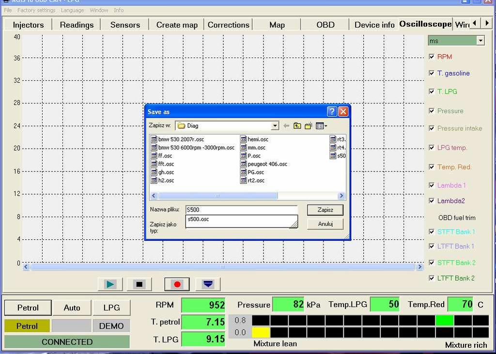
27 OSCILOSCOPES

28 29
Installation And Programming Manual of OPTIMA Eco Tec and OPTIMA Pro Tec OBD/CAN
 v1.03 [EN] Installation And Programming Manual of OPTIMA Eco Tec and OPTIMA Pro Tec OBD/CAN ALEX Zambrowska 4A, 16-001 Kleosin Poland tel./fax: +48 85 664 84 40 www.optimagas.pl e-mail: service@optimagas.pl
Instruction of connection and programming of the VECTOR controller
 Instruction of connection and programming of the VECTOR controller 1. Connection of wiring 1.1.VECTOR Connection diagram Fig. 1 VECTOR Diagram of connection to the vehicle wiring. 1.2.Connection of wiring
Instruction of connection and programming of the OSCAR-N controller
 Instruction of connection and programming of the OSCAR-N controller Table of content Paragraph Description Page 1 Installation of OSCAR-N sequential gas injection system 2 1.1 OSCAR-N sequential gas injection
Instruction of connection and programming of the OSCAR-N MINI controller
 Instruction of connection and programming of the OSCAR-N MINI controller Table of content Paragraph Description Page Introduction 2 1 Installation of OSCAR-N MINI sequential gas injection system 4 1.1
INSTRUCTIONS & MANUAL FOR THE AUTOGAS ECU. MA-V4 MA-V4mini MA-X6 MA-X8
 INSTRUCTIONS & MANUAL FOR THE AUTOGAS ECU MA-V4 MA-V4mini MA-X6 MA-X8 TABLE OF CONTENTS 1. Connection of MA-V4 2. The program features description 2.1 The indicators 2.2 Settings 2.3 Advanced 3. Calibration
EG DYNAMIC user manual
 Timing Advance Processor EG DYNAMIC user manual ver. 1.1.0 dated 2012-10-01 This instruction can be also downloaded from: http://www.europegas.pl/en/technical-support/service-manuals Latest software version
Preparing and programming of ESGI 2 LPG supply system manual
 Preparing and programming of ESGI 2 LPG supply system manual Part II Instruction of preparing and programming the ESGI system 1 Technical data of the central unit Vs Power supply voltage 0...16V V i_an
EG Configuration Center
 EG Configuration Center programming manual for EG BASICO EG AVANCE EG SUPERIOR sequential gas injection controllers ver. 2.0.0 dated 2015-04-09 This instruction, diagrams and training movies can be also
Using the Gratec Gasoline software
 Using the Gratec Gasoline software The Gratec Software is a sophisticated yet user friendly program in which configures the Gratec CNG or LPG system to perform with your vehicle. Software version 2.002
Connection and programming manual for. controller. (also available in the diagnostic software and at
 Connection and programming manual for controller (also available in the diagnostic software and at www.ac.com.pl) ver. 1.5 2015-06-30 CONTENTS 1. Set-up... 3 1.1. STAG 200 GoFast connection diagram...
Connection and Programming Manual for
 Connection and Programming Manual for controller (also available in the diagnostic software and at www.ac.com.pl) ver. 2.5 2011-02-16 Manufacturer: AC Spółka Akcyjna. 15-182 Białystok, ul. 27 Lipca 64,
LAMBDA SENSOR CONTROLLER
 LAMBDA SENSOR CONTROLLER INSTALLATION & PROGRAMMING MANUAL version : V1.77 -V1.79 Manufacturer: AC Spółka Akcyjna. 15-182 Białystok, ul. 27 Lipca 64, Poland tel. +48 85 7438148, fax +48 85 653 8649 www.ac.com.pl,
Installation and adjustment instruction for sequential/ synchronous/ sectional gas injection driver SEC ECO
 Installation and adjustment instruction for sequential/ synchronous/ sectional gas injection driver SEC ECO www.lecholpg.pl page 1 / 37 TABLE OF CONTENTS 1. General information 3 2. Recommendation concerning
Injection System. Description of the injection system calibration software COMPLETE VERSION
 Injection System Description of the injection system calibration software COMPLETE VERSION Table of Contents Introduction... 3 Main Menu... 4 Vehicle Configuration... 5 F1 Change-Over...6-7 F2 Lambda...8-9
new products R02 W02 STAG-4 QBOX PLUS 200 GoFast
 new products 2014 R02 W02 STAG-4 QBOX PLUS 200 GoFast STAG 200 GoFast STAG easy fast intuitive installation The key idea of the controller is an intuitive system focused on fast and easy installation,
Setup Tabs. Basic Setup: Advanced Setup:
 Setup Tabs Basic Setup: Password This option sets a password that MUST be entered to re-enter the system. Note: ProEFI can NOT get you into the calibration if you lose this password. You will have to reflash
Controller User Manual
 Controller User Manual 67R-01 4903 110R-00 4904 (information contained in this manual is also available in the diagnostics software help system and at the www.ac.com.pl website) ver. 1.6 2014-11-17. Table
INDEX 1 Introduction 2- Software installation 3 Open the program 4 General - F2 5 Configuration - F3 6 - Calibration - F5 7 Model - F6 8 - Map - F7
 SET UP MANUAL INDEX 1 Introduction 1.1 Features of the Software 2- Software installation 3 Open the program 3.1 Language 3.2 Connection 4 General - F2 4.1 The sub-folder Error visualization 5 Configuration
Lambda Control Fuel Adaptation and Fuel Trim
 Lambda Control Fuel Adaptation and Fuel Trim Q: What is Lambda and Lambda Control? A: In the case of a gasoline engine, the optimal mixture of air to fuel for complete combustion is a ratio of 14.7 parts
SEQUENT 56: MULTIPOINT SEQUENTIAL INJECTION SYSTEM FOR CYLINDER VEHICLES FIELD OF APPLICATION
 SEQUENT 56: MULTIPOINT SEQUENTIAL INJECTION SYSTEM FOR 5-6-8 CYLINDER VEHICLES FIELD OF APPLICATION Sequent 56 is the evolution of the multipoint injection system for LPG by BRC. New concept product, Sequent
spa DREAM XXI N Injection System Driving towards the future by OMVL
 spa Driving towards the future Injection System DREAM XXI N Software Manual Version 6.0.3 IC - ENG by OMVL REG Dream XXI-N 6.0.1 IC SW Manual - ENG Revision: 6.0.3.305 IC July 2010, OMVL S.p.A. Index:
Technical Installation Guide
 Technical Installation Guide ID Technical Document: DT_IS_GAI-005 Rev. Date Review n. Issued by Reviewed/ Approved 0 13/04/2007 First Issue Technical office ROS 1 19/02/2009 Second Issue Technical office
WORLD LEADER IN ALTERNATIVE FUEL SYSTEMS CALIBRATION PARAMETERS
 WORLD LEADER IN ALTERNATIVE FUEL SYSTEMS CALIBRATION PARAMETERS VSI-2.0 LPG UNIVERSAL KIT Version: Back V2.4 to Parameter 03-2018 Overview Page 1 of 53 Copyright Prins Autogassystemen B.V. 2018 Back to
INSTRUCTION MANUAL. Rev. 1.1 ISGI002
 INSTRUCTION MANUAL Rev.. ISGI00 BIGAS INTERNATIONAL AUTOGAS SYSTEMS S.r.l. Sede legale: Via A. De Gaspari, 3 Stabilimento: Via P. Nenni, 40 5009 Sesto Fiorentino Firenze ITALY Tel. 055475-0554043 Fax 05545977
PowerJet Sequential Injection INDEX. 1 Introduction 1.1 Features of the Software. 2- Software installation
 INDEX 1 Introduction 1.1 Features of the Software 2- Software installation 3 Open the program 3.1 Language 3.2 Connection 4 Folder General - F2. 4.1 The sub-folder Error visualization 5 Folder Configuration
MAKE OF AUTOMOBILE: ENGINE SET NUMBER 345/ NUMBER : 076/ DATE : VERSION NR : B
 MAKE OF AUTOMOBILE: TYPE: LOGAN PISTON DISPLACEMENT: 1600 NUMBER OF VALVES: 8 ENGINE NUMBER: K7M 710 TRANSMISSION TYPE ( MT / AT ) MT VEHICLE CATEGORIES M or N ( M ) TYPE VSI INJECTOR ( NUMBER + COLOR
Alternative Fuel Engine Control Unit
 1999 Chevrolet/Geo Cavalier (CNG) Alternative Fuel Engine Control Unit Table 1: AF ECU Function Parameters The (AF ECU) controls alternative fuel engine operation. The control unit monitors various engine
Emulator MAF and Oxygen Sensor SK-04a v5. User Guide.
 Emulator MAF and Oxygen Sensor SK-04a v5 User Guide www.sdsauto.com Content Page 1 Completeness 2 2 Principle of operation and purpose 3 3 Hardware installation 4 3.1 Connecting to the oxygen sensor 5
NEVO sequential gas injection system
 NEVO sequential gas injection system New sequential gas injection system NEVO Answer for market expectations Modern cars Demanding users Workshop time saving KME trademark Major assumptions of NEVO system
ProECU Mazda MX-5. Live Data Guide 2005-onward Model Year. v1.06
 ProECU Mazda MX-5 Live Data Guide 2005-onward Model Year v1.06 Live Data Live Data Display ProECU Mazda MX-5 can offer real time exceptionally high speed data display and the ability to log this displayed
Romano Injection System 01/11/2013 Rev. 0
 Romano Injection System E 01/11/2013 Rev. 0 Romano Injection System E Romano ECU E is the last generation phased sequential system designed by Romano Srl. This system is the result of the research and
L (LU4, LJ3, L88) used in Saab 9-5 ENGINE DIAGNOSTIC PARAMETERS
 used in Saab 9-5 ENGINE DIAGNOSTIC PARAMETERS") Catalytic Converter Monitoring P0420 Front vs. Rear O2 sensor signal Evaluated data 1,75 times FTP std 80 (unitless) Coolant temp Throttle Delta load, positive Delta load, negative Engine speed, man. trans
Catalytic Converter Monitoring P0420 Front vs. Rear O2 sensor signal Evaluated data 1,75 times FTP std 80 (unitless) Coolant temp Throttle Delta load, positive Delta load, negative Engine speed, man. trans
Controller User Manual
 Controller User Manual 67R-01 4903 110R-00 4904 10R-03 6616 (information contained in this manual is also available in the diagnostics software help system and at the www.ac.com.pl website) ver. 1.7.6
Parameter Setting Basic. Voltage Fuel 1 Fuel 2 Ignition 1 Ignition 2 Twin Injector COPYRIGHT 2016 HKS CO.LTD.ALLRIGHT RESERVED
 VERSION3.4 SOFTWARE MANUAL INDEX Initial Setting Injection Dead Time Map Ignition Cut RPM Input Max RPM Setting by Fuel Cut Intake Air Pressure Fuel Cut A/F Meter Setting Before Starting Mapping: Troubleshooting
Cannondale Diagnostic Tool Manual
 Cannondale Diagnostic Tool Manual For vehicles (ATV & Motorcycles) equipped with the MC1000 Engine Management System Software CD P/N 971-5001983 Data Cable P/N 971-5001984 POTENTIAL HAZARD Running the
CNG Kit For Four Wheeler
 CNG Kit For Four Wheeler Gasoline Fuel Systems India provides world class CNG kit LOVATO GAS S.p.A., Italy is manufacturing alternative fuel equipments since 1958 which are exported to 90 countries worldwide
ENGINE CONTROL SYSTEM. 1. General ENGINE 3VZ FE ENGINE
 ENGINE 3VZ FE ENGINE 69 ENGINE CONTROL SYSTEM 1. General The engine control system for the 3VZ FE engine has the same basic construction and operation as for the 2VZ FE engine. However, the sequential
STARDEX 0303, 0304, 0305, 0306, 0402, STARDEX Master Ultima. STARDEX Dimas. STARDEX Dimas Ultima
 New software STARDEX SISU user manual STARDEX 0303, 0304, 0305, 0306, 0402, 0403 STARDEX Master Ultima STARDEX Dimas STARDEX Dimas Ultima 2017 STARDEX GUI NEW FEATURES ENG Foreword For more than 15 years,
MAKE OF AUTOMOBILE: MODEL YEAR: 2007 SYSTEM APPROVAL NUMBER ( R115 ) VSI-LPG 10 ENGINE SET NUMBER 364/
 VSI-LPG 10 ENGINE SET NUMBER 364/") MAKE OF AUTOMOBILE: TYPE: FABIA PISTON DISPLACEMENT: 1400 NUMBER OF VALVES: 16 ENGINE NUMBER: BUD TRANSMISSION TYPE ( MT / AT ) MT VEHICLE CATEGORIES M or N M TYPE VSI INJECTOR ( NUMBER + COLOR ) 180/30410
MAKE OF AUTOMOBILE: TYPE: FABIA PISTON DISPLACEMENT: 1400 NUMBER OF VALVES: 16 ENGINE NUMBER: BUD TRANSMISSION TYPE ( MT / AT ) MT VEHICLE CATEGORIES M or N M TYPE VSI INJECTOR ( NUMBER + COLOR ) 180/30410
G - TESTS W/CODES - 2.2L
 G - TESTS W/CODES - 2.2L 1994 Toyota Celica 1994 ENGINE PERFORMANCE Toyota 2.2L Self-Diagnostics Celica INTRODUCTION If no faults were found while performing F - BASIC TESTING, proceed with self-diagnostics.
Overview of operation modes
 Overview of operation modes There are three main operation modes available. Any of the modes can be selected at any time. The three main modes are: manual, automatic and mappable modes 1 to 4. The MapDCCD
Propane and Gasoline Electronic Fuel Injection
 Zenith Electronic Engine Management System Propane and Gasoline Electronic Fuel Injection 1 Slide 1 2 Slide 2 Home Page System Advantages Block Diagram, Electronic Control Unit Inputs Output Controls System
MAKE OF AUTOMOBILE: PISTON DISPLACEMENT: NUMBER OF VALVES: ENGINE NUMBER: TRANSMISSION TYPE ( MT / AT ) VEHICLE CATEGORIES M or N PERSONEN AUTO ( M )
 VEHICLE CATEGORIES M or N PERSONEN AUTO ( M )") MAKE OF AUTOMOBILE: TYPE: WRANGLER PISTON DISPLACEMENT: 4000 cc NUMBER OF VALVES: 12 v ENGINE NUMBER: M3 TJ TRANSMISSION TYPE ( MT / AT ) MT VEHICLE CATEGORIES M or N PERSONEN AUTO ( M ) TYPE VSI INJECTOR
MAKE OF AUTOMOBILE: TYPE: WRANGLER PISTON DISPLACEMENT: 4000 cc NUMBER OF VALVES: 12 v ENGINE NUMBER: M3 TJ TRANSMISSION TYPE ( MT / AT ) MT VEHICLE CATEGORIES M or N PERSONEN AUTO ( M ) TYPE VSI INJECTOR
Subaru BRZ Toyota GT86 Scion FR-S
 RaceROM Features for Subaru BRZ Toyota GT86 Scion FR-S v1.8 Index Warning... 3 Introduction... 4 Feature list... 4 Supported Vehicle Models... 4 Availability... 4 Overview... 5 Map Switching**... 5 Speed
MAKE OF AUTOMOBILE: PISTON DISPLACEMENT: 1600 NUMBER OF VALVES: 16
 MAKE OF AUTOMOBILE: TYPE: MERIVA PISTON DISPLACEMENT: 1600 NUMBER OF VALVES: 16 ENGINE NUMBER: Z16XEP TRANSMISSION TYPE ( MT / AT ) MT VEHICLE TYPE M TYPE VSI INJECTOR ( NUMBER + COLOR ) 180/30430 ORANGE
COBB TUNING. AccessTUNER. USDM Mitsubishi Table Descriptions and Tuning Tips. Copyright 2008 Cobb Tuning Products, LLC. All Rights Reserved. P.
 COBB TUNING AccessTUNER TM USDM Mitsubishi Table Descriptions and P.1 Note: This is a list of tables available on all Mitsubishi AccessTUNER products. Not all tables are available in your software. Boost
INDEX 1.0 GENERAL RECOMMENDATION CONNECTION OF THE INJECTORS CUT-OFF WIRING...
 Installation Manual INDEX.0 GENERAL RECOMMENDATION... Pag. 4.0 CONNECTION OF THE INJECTORS CUT-OFF WIRING... Pag. 5. CONNECTION OF THE INJECTORS CUT-OFF WIRING ON THE ORIGINAL WIRING OF THE CAR... Pag.
AURORA SERIES GAUGES FUEL GAUGE SUGGESTED TOOLS AND MATERIALS. 3 3 /8 in (85.7 mm) PARTS LIST
 PARTS LIST") GAUGE INSTALLATION. Select mounting locations for the fuel gauge. 2. Cut a 2 /6 (52 mm) diameter hole for the gauge and test for proper fitmate. 3. Tighten the gauge with the enclosed Aurora Mounting Clamp
GAUGE INSTALLATION. Select mounting locations for the fuel gauge. 2. Cut a 2 /6 (52 mm) diameter hole for the gauge and test for proper fitmate. 3. Tighten the gauge with the enclosed Aurora Mounting Clamp
PSC1-003 Programmable Signal Calibrator
 PSC1-003 Programmable Signal Calibrator Description: The PSC1-003 Programmable Signal Calibrator provides precise calibration of fuel by adjusting fuel control signals. It can be used with naturally aspirated
MAKE OF AUTOMOBILE: PISTON DISPLACEMENT: 1300
 MAKE OF AUTOMOBILE: TYPE: YARIS PISTON DISPLACEMENT: 1300 NUMBER OF VALVES: 16 VVT-I ENGINE NUMBER: 2SZ-FE TRANSMISSION TYPE ( MT / AT ) AT VEHICLE CATEGORIES M or N M TYPE VSI INJECTOR ( NUMBER + COLOR
STAFOR HHO MAF/MAP fully digital and automatic enhancer (corrector). Installation manual. Version
. Installation manual. Version") STAFOR HHO MAF/MAP fully digital and automatic enhancer (corrector). Installation manual. Version 05.14. HHO hydrogen on demand dual fuel systems Introduction The present MAF/MAP Sensor Enhancer is fully
STAFOR HHO MAF/MAP fully digital and automatic enhancer (corrector). Installation manual. Version 05.14. HHO hydrogen on demand dual fuel systems Introduction The present MAF/MAP Sensor Enhancer is fully
CONTROL LAMBDA INSTALLATION MANUAL
 CONTROL LAMBDA INSTALLATION MANUAL The CONTROL LAMBDA is tailored to be installed on vehicles where the GASOLINE NGV dual conversion has to be done caring for environment with its highest performance.
Issue 2.0 December EPAS Midi User Manual EPAS35
 Issue 2.0 December 2017 EPAS Midi EPAS35 CONTENTS 1 Introduction 4 1.1 What is EPAS Desktop Pro? 4 1.2 About This Manual 4 1.3 Typographical Conventions 5 1.4 Getting Technical Support 5 2 Getting Started
Indian Speedometer and Body Control Module Service Tool Users Guide
 Indian Speedometer and Body Control Module Service Tool Users Guide Installing speedometer software to your computer 1. Go to the Indian Motorcycle Website: WWW. Indianmotorcycle.com 2. Log in to Service
COMPACT The smallest construction Full of possibilities in its class
 COMPACT The smallest construction Full of possibilities in its class Small size now even more options. Miniaturized Microprocessor Sequential Gas Injection Miniaturized Microprocessor Sequential Gas Injection
ProECU EVO X. Tuning Guide 2008-onward Model Year. v1.8
 ProECU EVO X Tuning Guide 2008-onward Model Year v1.8 Contents ECU Map Descriptions... 3 3D Maps... 3 Fuel Maps Shown in Live Data as Injector % and Injector ms... 3 High Octane... 3 Low Octane... 3 Ignition
DTC P0171 SYSTEM TOO LEAN (BANK 1) DTC P0174 SYSTEM TOO LEAN (BANK 2)
 DTC P0174 SYSTEM TOO LEAN (BANK 2)") 05498 DIAGNOSTICS DTC P0171 SYSTEM TOO LEAN (BANK 1) 05EXR06 DTC P0172 SYSTEM TOO RICH (BANK 1) DTC P0174 SYSTEM TOO LEAN (BANK 2) DTC P0175 SYSTEM TOO RICH (BANK 2) CIRCUIT DESCRIPTION The fuel trim is
05498 DIAGNOSTICS DTC P0171 SYSTEM TOO LEAN (BANK 1) 05EXR06 DTC P0172 SYSTEM TOO RICH (BANK 1) DTC P0174 SYSTEM TOO LEAN (BANK 2) DTC P0175 SYSTEM TOO RICH (BANK 2) CIRCUIT DESCRIPTION The fuel trim is
INSTALLATION MANUAL SEQUENTIAL INJECTION SYSTEMS - OBD SELF-ADAPTIVE SYSTEM - PARALLEL PETROL INJECTION - COMPACT 4 CYL. SYSTEM
 INSTALLATION MANUAL SEQUENTIAL INJECTION SYSTEMS - OBD SELF-ADAPTIVE SYSTEM - PARALLEL PETROL INJECTION - COMPACT 4 CYL. SYSTEM Installation Manual Revision 05, October 2013 1. GENERAL RECOMMENDATIONS
Prins autogassystemen b.v. Veldhoven
 Prins autogassystemen b.v. Veldhoven MOUNTING INSTRUCTION ENGINE CONVERSION SET MAKE OF AUTOMOBILE: TYPE: ASTRA PISTON DISPLACEMENT: 2000 cc MT NUMBER OF VALVES: 16V ENGINE NUMBER: X20XEV INJECTION SYSTEM:
Error codes Diagnostic plug Read-out Reset Signal Error codes
 Error codes Diagnostic plug Diagnostic plug: 1 = Datalink LED tester (FEN) 3 = activation error codes (TEN) 4 = positive battery terminal (+B) 5 = ground Read-out -Connect LED tester to positive battery
Rear Oxygen Sensor Monitoring
 Automobili Lamborghini s.p.a. OBDII MY 08 Section 7 Page 44 Rear Oxygen Sensor Monitoring Automobili Lamborghini s.p.a. OBDII MY 08 Section 7 Page 45 Oxygen Sensor Heater Monitoring Automobili Lamborghini
EPAS Desktop Pro Software User Manual
 Software User Manual Issue 1.10 Contents 1 Introduction 4 1.1 What is EPAS Desktop Pro? 4 1.2 About This Manual 4 1.3 Typographical Conventions 5 1.4 Getting Technical Support 5 2 Getting Started 6 2.1
Block schematic diagram of EGS-DI
 GENERAL INFORMATION The system EGS -DI is intended to convert diesel engine onto gas-diesel blend. It could be used for engines with or without turbocharge, both. As a gas, Liquefied Petroleum Gas (LPG)
How to use the NOx sensor emulator NOXEM
 How to use the NOx sensor emulator NOXEM 129 130 1. Replace the existing NOx sensor to NOx emulator 2. Encode replacement of NOx sensor, using ISTA D 3. Encode replacement of NOx catalytic converter, using
SentryGOLD Fully-Automated Fuel Management System
 SentryGOLD Fully-Automated Fuel Management System Trak s SentryGOLD Fully Automated Fuel Management System provides the highest level of security for your fleet and the highest level of accuracy for your
MAKE OF AUTOMOBILE: TYPE: V 70 PISTON DISPLACEMENT: 2521 NUMBER OF VALVES:
 MAKE OF AUTOMOBILE: TYPE: V 70 PISTON DISPLACEMENT: 2521 NUMBER OF VALVES: 20V ENGINE NUMBER: B5254T TRANSMISSION TYPE ( MT / AT ) AT VEHICLE CATEGORIES M or N PASSENGER CAR ( M ) TYPE VSI INJECTOR (COLOUR
ProECU Subaru BRZ Toyota GT86 Scion FR-S
 ProECU Subaru BRZ Toyota GT86 Scion FR-S DTC List 2012-onward Model Year v1.0 Engine DTC List P000A Camshaft Position "A" - Timing Slow Response Bank 1 P000B Camshaft Position "B" - Timing Slow Response
MAKE OF AUTOMOBILE: 316 / 318i E46 NUMBER OF VALVES:
 MAKE OF AUTOMOBILE: TYPE: 316 / 318i E46 PISTON DISPLACEMENT: 1800 2000 cc NUMBER OF VALVES: 16V ENGINE NUMBER: N42B18A / N42B20A TRANSMISSION TYPE ( MT / AT ) MT VEHICLE CATEGORIES M or N M TYPE VSI INJECTOR
OMEM200 Tuning Manual 3v Series ECU. Tuning Manual OMEM200.
 200 Series ECU Tuning Manual OMEM200 www.omextechnology.com 0 1 Introduction... 3 1.1 What this manual covers... 3 1.2 Notation Used in This Manual... 3 2 Software... 4 3 Sensor Setup... 5 3.1 Throttle
 Autoadaptation mode - Inj Maps In this mode, Autoadaptation is based upon maps of petrol injector opening times. Therefore, the first and the most important step is to create a map of petrol injector opening
Diagnostic Trouble Code (DTC) memory, checking and erasing
 memory, checking and erasing") Page 1 of 49 01-12 Diagnostic Trouble Code (DTC) memory, checking and erasing Check DTC Memory (function 02) - Connect VAS5051 tester Page 01-7 and select vehicle system "01 - Engine electronics". Engine
Page 1 of 49 01-12 Diagnostic Trouble Code (DTC) memory, checking and erasing Check DTC Memory (function 02) - Connect VAS5051 tester Page 01-7 and select vehicle system "01 - Engine electronics". Engine
GENERAL MOTORS SERVICE PARTS OPERATION 6200 Grand Pointe Drive, Grand Blanc, MI 48439
 LS IGNITION CONTROLLER 19355418 Ignition Control for Carbureted LS Series Engines (24x Crankshaft Index/1x Camshaft Index, 58x Crankshaft Index/4x Camshaft Index) Parts Included Quantity Ignition Controller
ARTICLE BEGINNING INTRODUCTION SELF-DIAGNOSTIC SYSTEM RETRIEVING DTCS ENGINE PERFORMANCE Volkswagen Self-Diagnostics - Gasoline
 Article Text ARTICLE BEGINNING 1996 ENGINE PERFORMANCE Volkswagen Self-Diagnostics - Gasoline Cabrio, Golf III, GTI, Jetta III, Passat INTRODUCTION If no faults were found while performing preliminary
ECT Display Driver Installation for AP2 Module
 ECT Display Driver Installation for AP2 Module Overview The ECT Display Driver is a small module with a removable wire harness that mounts behind the driver's foot well cover. All wiring connections are
Introduction. Drenth Motorsport Gearboxes Fleuweweg AG Enter The Netherlands Phone: +31 (0) Fax: +31 (0)
 Fax: +31 (0)") 25.03.0023 Introduction The display unit comes with a software application. With the software application information shown on the display can be adjusted. There are different modes to adjust: the shape
25.03.0023 Introduction The display unit comes with a software application. With the software application information shown on the display can be adjusted. There are different modes to adjust: the shape
INDEX. 1.Safety Precautions and Warnings...3
 INDEX 1.Safety Precautions and Warnings...3 2. General Information...5 2.1 On-Board Diagnostics (OBD) II... 5 2.2 Diagnostic Trouble Codes (DTCs)... 6 2.3 Location of the Data Link Connector (DLC)...7
NTK2000 UEGO OPERATORS MANUAL
 NTK2000 UEGO OPERATORS MANUAL CONTENTS Introduction...page 1 Uego Sensor...page3 Installation...page4 Operation...page5 Software...page6 M&W LCD...page9 Kit Components...page10 Output Graphs...page11 Specifications...page16
Handheld Controller Feature Definitions
 Basic Settings: These values and options allow Engine CID = Total Engine cubic inches Cam Mild-Wild 1-4 = This is the way to select a specific volumetric efficiency table that is specially tailored to
MAKE OF AUTOMOBILE: ENGINE SET NUMBER 366/
 MAKE OF AUTOMOBILE: TYPE: SORENTO PISTON DISPLACEMENT: 3300 NUMBER OF VALVES: 24 ENGINE NUMBER: G6DB TRANSMISSION TYPE ( MT / AT ) MT VEHICLE CATEGORIES M or N M TYPE VSI INJECTOR ( NUMBER + COLOR ) 180/30340
POLAR FIS ADVANCED USER MANUAL FOR AUDI A3/S3/RS3 8P
 POLAR FIS ADVANCED USER MANUAL FOR AUDI A3/S3/RS3 8P Polar FIS for Audi A3/S3/RS3 8P User manual Sheet: 1 of 24 I N D E X 1. INTRODUCTION 3 2. CONTROLS 4 3. CONFIGURATION MENU 5 3.1. SCREEN. 6 3.1.1. SCREEN-VISUALIZATION.
MODEL YEAR: SYSTEM APPROVAL NUMBER ( R115 ) R ENGINE SET NUMBER 354/
 R ENGINE SET NUMBER 354/") MAKE OF AUTOMOBILE: MERECEDES TYPE: E200 W211 PISTON DISPLACEMENT: 1796 NUMBER OF VALVES: 16 ENGINE NUMBER: M271 TRANSMISSION TYPE ( MT / AT ) AT VEHICLE CATEGORIES M or N M TYPE VSI INJECTOR ( NUMBER
MAKE OF AUTOMOBILE: MERECEDES TYPE: E200 W211 PISTON DISPLACEMENT: 1796 NUMBER OF VALVES: 16 ENGINE NUMBER: M271 TRANSMISSION TYPE ( MT / AT ) AT VEHICLE CATEGORIES M or N M TYPE VSI INJECTOR ( NUMBER
Fuel Metering System Component Description
 1999 Chevrolet/Geo Tahoe - 4WD Fuel Metering System Component Description Purpose The function of the fuel metering system is to deliver the correct amount of fuel to the engine under all operating conditions.
Copyright Nistune Developments rev4
 Copyright Nistune Developments 2014-2017 rev4 Boost Sensor Register Nissan has added an additional boost sensor to the Nissan ECU: Boost pressure sensor. Uses a vaccum/boost equipped MAP sensor capable
I. CONNECTING TO THE GCU
 I. CONNECTING TO THE GCU GCU7 and newer units use CAN BUS to connect to the computer so special interface is needed. GCU Interface uses FTDI drivers which are usually already installed by default. If you
user guide win trijekt for trijekt premium user guide win trijekt for trijekt premium
 Page 1/68 win trijekt for trijekt premium trijekt GmbH Wielandstr. 3 D-57482 Wenden Phone: +49(0)2762-98825-0 Fax: +49(0)2762-98825-29 e-mail: info@trijekt.de www.trijekt.de Page 2/68 trijekt GmbH, 06.2012
Glossary. 116
 Sequential Fuel Injection Sequential means that each injector for each cylinder is triggered only one time during the engine s cycle. Typically the injector is triggered only during the intake stroke.
MAKE OF AUTOMOBILE: ENGINE SET NUMBER 337/
 MAKE OF AUTOMOBILE: TYPE: NITRO PISTON DISPLACEMENT: 3700 NUMBER OF VALVES: 12V ENGINE NUMBER: V6 TRANSMISSION TYPE ( MT / AT ) AT VEHICLE CATEGORIES M or N M TYPE VSI INJECTOR ( NUMBER + COLOR ) 180/30330
HELSINKI, FINLAND, 2015 COMMON RAIL INJECTORS TESTER STARDEX 0304
 HELSINKI, FINLAND, 2015 COMMON RAIL INJECTORS TESTER STARDEX 0304 Safety rules for working with STARDEX 0304 device. Before using the device STARDEX 0304 (further the device ) read this manual carefully.
DTC P0420 CATALYST SYSTEM EFFICIENCY BELOW THRESHOLD (BANK 1) DTC P0430 CATALYST SYSTEM EFFICIENCY BELOW THRESHOLD (BANK 2)
 DTC P0430 CATALYST SYSTEM EFFICIENCY BELOW THRESHOLD (BANK 2)") DIAGNOSTICS DTC P0420 CATALYST SYSTEM EFFICIENCY BELOW THRESHOLD (BANK 1) 05551 05BNU11 DTC P0430 CATALYST SYSTEM EFFICIENCY BELOW THRESHOLD (BANK 2) MONITOR DESCRIPTION The ECM uses sensors mounted before
DIAGNOSTICS DTC P0420 CATALYST SYSTEM EFFICIENCY BELOW THRESHOLD (BANK 1) 05551 05BNU11 DTC P0430 CATALYST SYSTEM EFFICIENCY BELOW THRESHOLD (BANK 2) MONITOR DESCRIPTION The ECM uses sensors mounted before
MODEL YEAR: 2007 SYSTEM APPROVAL NUMBER ( R115 ) R ENGINE SET NUMBER 350/
 R ENGINE SET NUMBER 350/") MAKE OF AUTOMOBILE: TYPE: KALINA 1117/ 1118 / 1119 PISTON DISPLACEMENT: 1600 NUMBER OF VALVES: 8 ENGINE NUMBER: 21114 TRANSMISSION TYPE ( MT / AT ) MT VEHICLE CATEGORIES M or N M TYPE VSI INJECTOR ( NUMBER
MAKE OF AUTOMOBILE: TYPE: KALINA 1117/ 1118 / 1119 PISTON DISPLACEMENT: 1600 NUMBER OF VALVES: 8 ENGINE NUMBER: 21114 TRANSMISSION TYPE ( MT / AT ) MT VEHICLE CATEGORIES M or N M TYPE VSI INJECTOR ( NUMBER
TCwin AND THE STC THROTTLE CONTROLLER... 3 INSTALLATION... 3 SOFTWARE INSTALLATION... 3 DEFINITION OF TERMS... 4 MAP EDITING KEYS... 4 DIAGNOSTICS...
 1 TCwin AND THE STC THROTTLE CONTROLLER... 3 INSTALLATION... 3 SOFTWARE INSTALLATION... 3 DEFINITION OF TERMS... 4 MAP EDITING KEYS... 4 DIAGNOSTICS... 5 WARNING LIGHT FLASH PATTERNS... 6 HOLDING PWM MAP...
AS-4000 OPERATING INSTRUCTIONS (PS-5000)
") AS-4000 OPERATING INSTRUCTIONS (PS-5000) BASIC OPERATIONS This unit is a state-of-the-art combination of a vehicle alarm and remote starter system. Start by familiarizing yourself with the alarm functions
AS-4000 OPERATING INSTRUCTIONS (PS-5000) BASIC OPERATIONS This unit is a state-of-the-art combination of a vehicle alarm and remote starter system. Start by familiarizing yourself with the alarm functions
COMMON RAIL SYSTEM (CRS)
") MITSUBISHI 4N13, 4N14 ENGINES COMMON RAIL SYSTEM (CRS) Issued : November 2010 Applicable Vehicle : Vehicle Manufacturer MITSUBISHI Vehicle Name LANCER ASX OUTLANDER 50000023E 2010 DENSO CORPORATION All
MITSUBISHI 4N13, 4N14 ENGINES COMMON RAIL SYSTEM (CRS) Issued : November 2010 Applicable Vehicle : Vehicle Manufacturer MITSUBISHI Vehicle Name LANCER ASX OUTLANDER 50000023E 2010 DENSO CORPORATION All
DTC P1415 Secondary Air Injection (AIR) System Bank 1
 System Bank 1") Page 1 of 5 2000 GMC Truck GMC K Sierra - 4WD Sierra, Silverado, Suburban, Tahoe, Yukon (VIN C/K) Service Manual Document ID: 546887 DTC P1415 Secondary Air Injection (AIR) System Bank 1 Circuit Description
Page 1 of 5 2000 GMC Truck GMC K Sierra - 4WD Sierra, Silverado, Suburban, Tahoe, Yukon (VIN C/K) Service Manual Document ID: 546887 DTC P1415 Secondary Air Injection (AIR) System Bank 1 Circuit Description
Powertrain DTC Summaries EOBD
 Powertrain DTC Summaries Quick Reference Diagnostic Guide Jaguar X-TYPE 2.0 L 2002.25 Model Year Refer to page 2 for important information regarding the use of Powertrain DTC Summaries. Jaguar X-TYPE 2.0
DTC P0174 Fuel Trim System Lean Bank 2
 2000 Chevrolet/Geo S10 Pickup - 4WD DTC P0174 Fuel Trim System Lean Bank 2 Circuit Description In order to provide the best possible combination of driveability, fuel economy, and emission control, the
SP4 DOCUMENTATION. 1. SP4 Reference manual SP4 console.
 SP4 DOCUMENTATION 1. SP4 Reference manual.... 1 1.1. SP4 console... 1 1.2 Configuration... 3 1.3 SP4 I/O module.... 6 2. Dynamometer Installation... 7 2.1. Installation parts.... 8 2.2. Connectors and
SimMotor User Manual Small Engine Simulator and HIL V COPY RIGHTS ECOTRONS LLC All rights reserved
 V2.3.1 SimMotor User Manual Small Engine Simulator and HIL V2.3.1 COPY RIGHTS ECOTRONS LLC All rights reserved Http://www.ecotrons.com Table of Contents Read before you start:...1 Why do I need SimMotor?...2
5. Control System CONTROL SYSTEM FUEL INJECTION (FUEL SYSTEM) A: GENERAL FU(H4DOTC)-29
 A: GENERAL FU(H4DOTC)-29") W1860BE.book Page 29 Tuesday, January 28, 2003 11:01 PM 5. Control System A: GENERAL The ECM receives signals from various sensors, switches, and other control modules. Using these signals, it determines
W1860BE.book Page 29 Tuesday, January 28, 2003 11:01 PM 5. Control System A: GENERAL The ECM receives signals from various sensors, switches, and other control modules. Using these signals, it determines
1. ENGINE ECU AND OTHER COMPONENTS
 09-3 EGINE CONTROL SYSTEM 1. ENGINE ECU AND OTHER COMPONENTS ECU/Barometric Sensor Camshaft Position Sensor HFM Sensor / Intake Air Temperature Sensor Fuel Filter (Water Sensor) Preheating Relay Accelerator