User s Manual. XPert Filtered Balance Enclosures & Protector XVS Ventilation Stations. Models
|
|
|
- Mervyn Green
- 6 years ago
- Views:
Transcription


1 User s Manual XPert Filtered Balance Enclosures & Protector XVS Ventilation Stations Models 2' XPert Balance Enclosures , , , , , , , , , ' 4' 5' 6' 8' , , , , , , , , , , , , , , , , , , , , , , , , , , , , , , , , , , , , , , , , , , , , , , , , , , , , , , , , , XVS Ventilation Stations 2' 3' 4' 5' , , , , , , , , , , , , , , , , , , , , , , , , , , , , , , , , , , , , , , , , , ' , , , , , , , , , , , , , , ' , , , , , , , , , , , , , , To receive important product updates, complete your product registration card online at register.labconco.com Please read the User s Manual before operating the equipment. Labconco Corporation 8811 Prospect Avenue Kansas City, MO , Fax Labconco@labconco.com Home Page
2 Copyright 2004, 2007, 2009, 2010 Labconco Corporation. All rights reserved. The information contained in this manual and the accompanying products are copyrighted and all rights reserved by Labconco Corporation. Labconco Corporation reserves the right to make periodic design changes without obligation to notify any person or entity of such change. Warranty Labconco provides a warranty on all parts and factory workmanship. The warranty includes areas of defective material and workmanship, provided such defect results from normal and proper use of the equipment. The warranty for all Labconco products will expire one year from date of installation or two years from date of shipment from Labconco, whichever is sooner, except the following; Purifier Logic Biological Safety Cabinets and PuriCare Lab Animal Research Stations carry a three-year warranty from date of installation or four years from date of shipment from Labconco, whichever is sooner. SteamScrubber & FlaskScrubber Glassware Washers carry a two-year warranty from date of installation or three years from date of shipment from Labconco, whichever is sooner. Blood Drawing Chairs carry a ten year warranty. Carts carry a lifetime warranty. Glassware is not warranted from breakage when dropped or mishandled. This limited warranty covers parts and labor, but not transportation and insurance charges. In the event of a warranty claim, contact Labconco Corporation or the dealer who sold you the product. If the cause is determined to be a manufacturing fault, the dealer or Labconco Corporation will repair or replace all defective parts to restore the unit to operation. Under no circumstances shall Labconco Corporation be liable for indirect, consequential, or special damages of any kind. This statement may be altered by a specific published amendment. No individual has authorization to alter the provisions of this warranty policy or its amendments. Lamps and filters are not covered by this warranty. Damage due to corrosion or accidental breakage is not covered. Returned or Damaged Goods Do not return goods without the prior authorization from Labconco. Unauthorized returns will not be accepted. If your shipment was damaged in transit, you must file a claim directly with the freight carrier. Labconco Corporation and its dealers are not responsible for shipping damages. The United States Interstate Commerce Commission rules require that claims be filed with the delivery carrier within fifteen (15) days of delivery. Limitation of Liability The disposal and/or emission of substances used in connection with this equipment may be governed by various federal, state, or local regulations. All users of this equipment are required to become familiar with any regulations that apply in the user s area concerning the dumping of waste materials in or upon water, land, or air and to comply with such regulations. Labconco Corporation is held harmless with respect to user s compliance with such regulations. Contacting Labconco Corporation If you have questions that are not addressed in this manual, or if you need technical assistance, contact Labconco s Customer Service Department or Labconco s Product Service Department at or , between the hours of 7:00 a.m. and 6:00 p.m., Central Standard Time. Part # , Rev. F ECO F773
3 TABLE OF CONTENTS CHAPTER 1: INTRODUCTION 1 CHAPTER 2: PREREQUISITES 2 Support, Vibration and Movement Requirements 3 Temperature Variation Requirements 3 Humidity and Static Electricity Requirements 4 Location and Air Current Requirements 5 Exhaust and Blower Requirements 6 Remote Blowers (Roof Mounted) 7 FilterMate Portable Exhausters 8 Electrical Requirements 9 Space Requirements 9 CHAPTER 3: GETTING STARTED 10 Unpacking the Enclosure 11 Install the Enclosure on a Supporting Structure & Work Surface 11 Connecting to the Vented Enclosure Exhaust System 13 Connecting the Electrical Supply 17 Sealing the Vented Enclosure to the Work Surface 17 Validating the Vented Enclosure 17 CHAPTER 4: HIGH PERFORMANCE FEATURES AND SAFETY PRECAUTIONS 18 High Performance Features 18 Safety Precautions 24 CHAPTER 5: USING YOUR ENCLOSURE 25
4 CHAPTER 6: MAINTAINING YOUR ENCLOSURE 27 Routine Maintenance Schedule 28 Guardian 500 Airflow Monitor Kit No or Guardian 500 Component Identification 29 Guardian 500 Installation Procedure 30 Guardian 500 Calibration Procedure 32 Guardian 500 Alarm Activation 32 Guardian Digital 1000 Kit No or Guardian Digital 1000 Operation 34 Guardian Digital 1000 Installation Procedure 34 Guardian Digital 1000 Calibration 37 Digital 1000 Alternate Calibration Procedure Constant Volume Conditions 38 CHAPTER 7: ACCESSORIZING YOUR ENCLOSURE 41 Work Surfaces 43 Guardian Digital Airflow Monitor or Guardian Fluorescent Light Kit 43 Exhaust Transition Adapters & Dual Exhaust Connectors 44 Remote Blowers 44 Exhaust Dampers 45 FilterMate Portable Exhausters and Filters 45 Storage Cabinets 46 Utility Shelf Kit 47 Hose, Hose Clamps and Hose Kits 47 CHAPTER 8: TROUBLESHOOTING 48 APPENDIX A: REPLACEMENT PARTS 49 APPENDIX B: DIMENSIONS 52 APPENDIX C: SPECIFICATIONS 53 APPENDIX D: BALANCE STABILITY 54 DECLARATION OF CONFORMITY 55

5 Chapter 1: Introduction Congratulations on your purchase of a Labconco XPert Balance Enclosure or Protector XVS Ventilation Station. Your high performance enclosure is designed to protect you by providing superior containment while conserving energy at OSHA approved low flow velocities as low as 60 feet per minute. It is the result of Labconco s more than 50 years experience in manufacturing fume hoods. The XPert Balance Enclosure or Protector XVS Ventilation Station has been engineered to provide maximum containment. It will effectively contain toxic, noxious, or other harmful materials when properly installed. The XPert or XVS offers many unique features to enhance safety, performance, and energy savings. To take full advantage of them, please acquaint yourself with this manual and keep it handy for future reference. If you are unfamiliar with how high performance vented enclosures operate, please review Chapter 4: High Performance Features and Safety Precautions before you begin working in the enclosure. Even if you are an experienced user, please review Chapter 5: Using Your Vented Enclosure, which describes the XPert or XVS features so that you can use the vented enclosure efficiently. 3' XPert Filtered Balance Enclosure is shown with Black Solid Epoxy Work Surface and Protector Standard Storage Cabinet Work Surface, base cabinet, blower and ductwork or FilterMate Portable Exhauster must be ordered separately. Product Service
6 Chapter 2: Prerequisites Before you install the vented enclosure, you need to prepare your site for installation. Carefully examine the location where you intend to install the vented enclosure. You must be certain that the area is level and of solid construction. In addition, a dedicated source of electrical power should be located near the installation site to power the accessory FilterMate Portable Exhauster, balance or other apparatus. Additionally, a balance should be strategically placed in the lab to provide efficient workflow. Carefully read this chapter to learn the requirements for your installation site: The support, vibration and movement requirements. The temperature variation requirements. The humidity and static electricity requirements. The location and air current requirements. The exhaust and blower requirements. The electrical power requirements. The space requirements. Refer to Appendix B: XPert/XVS Dimensions for complete enclosure dimensions. Refer to Appendix C: XPert/XVS Specifications for complete vented enclosure electrical and environmental conditions, specifications and requirements. 2 Product Service
7 Chapter 2: Prerequisites Support, Vibration and Movement Requirements At a minimum, the supporting structure usually consists of a base cabinet and chemically resistant work surface. XPert and XVS: When setting up a chemical station not used for weighing powders, a mobile stand or cart is allowable. The ability for analytical balances to accommodate vibration varies with type and brand. More advanced balances have improved reliability, however in the preparation of a balance enclosure site, please consider the following: Avoid tubular stands or carts that have the potential of moving when touched. Work surfaces should be of a thick rigid material that remains stable when buttons are pressed. An epoxy benchtop or accessory work surface is a minimum requirement. A bench that is rigidly mounted to the floor or fixed to the wall, but not both, may be appropriate. The corners of a building typically have less vibration than the center. The bench with the balance enclosure should not contain any vibrationproducing equipment, such as shakers or pumps. Marble, granite or epoxy balance tables are generally recommended by the manufacturers of analytical and microbalances. (See the installation instructions in Chapter 3). Marble slabs within the balance enclosure with dampening pads are also an effective low cost means of controlling vibration. Temperature Variation Requirements XPert: The extent the balance readings are influenced by temperature variations is a function of the balance design. Most manufacturers would suggest that a temperature drift of 1-2 C is generally tolerable. Only validation through your Operational Qualification protocol can define what is acceptable. To minimize the potential for temperature variations: Product Service
8 Chapter 2: Prerequisites Never install balances near heating sources such as radiators and hot plates. Avoid incandescent lighting of the enclosure where radiant heat produced will raise temperatures. (See Chapter 7 for adding an accessory fluorescent light kit). Do not place the balance and enclosure on a bench that would receive direct sunlight. Humidity and Static Electricity Requirements XPert: Electrostatics can be troublesome in a balance enclosure. It is important to understand and, to the extent possible, control static charges. An electrostatic charged vessel, sample or enclosure can apply forces and lead to errors in weighing. The repulsion or attraction can be detected with micro, semi micro and analytical balances. Static charges can also lead to particulates being attracted to surfaces within the balance enclosure. Containment of harmful powders, prevention of cross-contamination and clean up is all enhanced when static attraction of powders is minimized. The construction of the XPert Balance Enclosure avoids the use of plastics, which are highly insulative. The advantages to the glass and epoxy-coated metal construction are twofold. 1. The enclosure does not contribute high electrostatic forces affecting the precision of the balance. 2. The attraction and ultimate accumulation of powders, (hazardous or nuisance), are minimized on the inside of the enclosure. To correct or ensure against electrostatic issues, the following additional measures may be prescribed to improve weighing operations. Maintain a humidity level between 45 and 60%. The ability to sustain this humidity range can be challenging depending upon the regional climate and HVAC system. Ionizers in various forms (guns, bars and blowers) are effective ways to flood an area with ions and essentially neutralize electrostatic electricity. 4 Product Service
9 Chapter 2: Prerequisites Background on Electrostatics or Static Electricity Electrostatic charges on a surface such as the wall of a balance enclosure are not created by moving air. Gases do not cause the charge. Impurities within the air impinging upon surfaces dictate the polarity and magnitude of the charge. The process, triboelectrification, occurs when the friction of the dust particles contact the surface and electrons move across the interface. The ability of a material to become polarized is a property known as permittivity. On highly insulative materials like acrylic, ions or charged molecules are strongly bound to the surface by polarization forces. The higher the force, the higher is the permittivity value of the material. It is suggested that the use of high permittivity materials, such as plastic be avoided. Since static electricity is a surface phenomenon, materials can also be classified by their surface resistivity measured in ohms per square. The table below lists the surface resistivity of various classes of material. Surface Resistivity Table Material Surface Resistivity Example Conductive Ω per square Skin, Metals Static dissipative Ω per square Glass Antistatic Ω per square Polyethylene bag Insulative Ω per square Acrylic, Packing foam, Styrofoam Location and Air Current Requirements The XPert Balance Enclosure and XVS Ventilation Station both have been designed to contain hazards by negating typical cross drafts and movements within the opening. Air movement does not affect most modern balances with draft shields. However, as a precautionary measure of safety and a higher level of quality management, it is recommended that the enclosure be placed in such an area to avoid: High traffic areas where walking might cause an air disturbance or be a nuisance to balance readings. Overhead or wall HVAC diffusers, fans, radiators or other lab equipment producing air currents. Next to doorways or windows that may be opened. Product Service
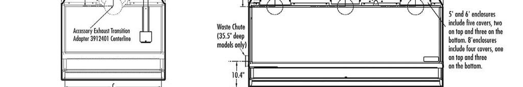
10 Chapter 2: Prerequisites Exhaust and Blower Requirements The exhaust connection has been designed to accept a 2" x 10" (5.1cm x 25.4cm) nominal exhaust collar. The enclosure has two possible exhaust connections with either the top exhaust open and the bottom exhaust closed or vise versa. The bottom exhaust connection is primarily used in installations where the hose or ductwork needs to be concealed. Labconco offers accessory transition adapters for the top or bottom exhaust connection to either a 5" hose or 6" duct. See Chapter 7 for ordering any of these accessories. For house exhaust, only one exhaust connection is required for the 2' through 6' enclosures and two exhaust connections are required on the 8' enclosure. Data for the exhaust volume and enclosure static pressure loss are listed for each enclosure model at face velocities of 60, 80 and 100 fpm. When using the accessory FilterMate Portable Exhausters, it requires the 5" Transition Adapter , which is sold with the FilterMate. Multiple FilterMate Portable Exhausters require the airflow to be properly balanced. The 5', 6' and 8' enclosures require two or three FilterMate Portable Exhausters dependent on face velocity and size. Enclosure Width 2' 3' 4' 2' 3' 4' 5' 6' 8' 5' 6' 8' Enclosure Height 22.75" 8" Sash 22.75" 8" Sash 22.75" 8" 32" 10" Sash 32" 10" Sash 32" 10" Sash 22.75" 8" Sash 22.75" 8" Sash 22.75" 8" Sash 32" 12" Sash 32" 12" Sash 32" 12" Sash Model Description 2' XPert/2' XVS 3' XPert/3' XVS 4' XPert/4' XVS Tall 2' XPert/2' XVS Tall 3' XPert/3' XVS Tall 4' XPert/4' XVS 5' XPert 6' XPert 8' XPert Tall 5' XPert Tall 6' XPert Tall 8' XPert Face Velocity (fpm) Exhaust Volume (CFM) Static Pressure Loss (in w.g.).02".03".05".04".06".10".06".10".16".03".05".08".06".10".15".09".16".24".08".15".23".12".21".32".07".12".18".20.35".54".27".48".75".15".27.42" Number of Required FilterMates N/A Product Service
11 Chapter 2: Prerequisites Proper blower selection can be determined from these exhaust requirements and the total system static pressure loss. The enclosure must be connected to a dedicated blower, a house exhaust system or a dedicated filtered exhauster, such as a Labconco FilterMate. When using multiple FilterMates, the airflow must be balanced. Labconco offers accessory remote blowers listed next and in Chapter 7. Remote Blowers (Roof-Mounted) A). 1/4 hp direct drive. Corrosion-resistant epoxy-coated steel housing and wheel. Blower inlet is 6" ID. Outlet dimensions are a rectangular 4.25" x 7.38" OD. See dimensional data in Chapter 7. Static Pressure Inches of H 2 O S.P. 0.0" 0.125" 0.25" 0.50" 0.75" 0.87" CFM Catalog # Description Shipping Wt. lbs./kg Remote Blower, 115 volts, 60 Hz, 4.4 amps 35/ Remote Blower, 115/230 volts, 50 Hz, 5.6/2.8 amps 35/ Explosion-Proof Remote Blower, 115 volts, 60 Hz, 4.4 amps 40/18 B). 1/4 hp or 1/3 hp belt drive with adjustable sheave to change RPM. Corrosion-resistant epoxy-coated steel housing and wheel. Blower inlet is 10.87" ID. Outlet dimensions are a rectangular 5.5" x 10" OD. See dimensional data in Chapter 7. Catalog # HP Description CFM@RPM Ranges at Static Pressure (in H 2 0) Std. EP.25".38".50".62".75".88" 1.00" /4 Remote Blower, 115V, 60 Hz, 4.4 A 540@ @ @ @ @1060 Explosion Proof /4 Blower 115V, 60 Hz, 4.5 A 720@ @ @ @1060 Remote Blower, /3 115V, 60 Hz, 6.1 A 760@ @ @ @ @ @1220 Explosion Proof /3 Blower, 115V, 60 Hz, 6.4 A 850@ @ @ @ @ @1260 If the enclosure is connected directly to a house exhaust system, an adjustable damper (or valve) must be installed to control the airflow properly. This is equally important when a house exhaust system is controlling multiple balance enclosures or ventilation stations. See Chapter 7 for ordering an accessory adjustable damper. Product Service
12 Chapter 2: Prerequisites FilterMate Portable Exhausters (Filtered Room Exhaust or Outside) For filtered exhauster selection, Labconco offers FilterMate Portable Exhausters capable of exhausting up to 280 cfm of HEPA filtered air or up to 220 cfm of combination HEPA/Carbon filtered air. These airflows are possible when connected to the enclosure with 8' of 5" diameter hose. HEPA and Carbon filters are available and detailed below, as well as in Chapter 7. For airflows greater than these listed use multiple FilterMates. Labconco offers FilterMate Portable Exhausters listed below and in Chapter 7. FilterMate Portable Exhausters Catalog Exhaust Exhaust Number Voltage Filter Airflow (cfm) Connection Volt/60 Hz HEPA 280 None Volt/60 Hz Carbon 280 None Volt/60 Hz HEPA 280 Canopy to outside Volt/60 Hz HEPA/Carbon 220 None Volt/60 Hz Carbon/Carbon 220 None Volt/50 Hz HEPA 280 None Volt/50 Hz Carbon 280 None Volt/50 Hz HEPA 280 Canopy to outside Volt/50 Hz HEPA/Carbon 220 None Volt/50 Hz Carbon/Carbon 220 None If the outlet of the FilterMate Exhauster is connected to the house exhaust system it is recommended that (115 Volt) or (230 Volt) be ordered as a thimble connection is built into the exhaust with a 6" nominal exhaust. HEPA Filter Part # is 99.99% efficient for particles 0.3 micron. HEPA Filter with Bag-In/Bag-Out Bag Part # Helps contain particulate matter during filter changing operations. Carbon Filters Provides granular activated carbon or treated carbon. Filter Classification Part # Carbon lbs. Organic Vapors # activated Formaldehyde # treated Ammonia # treated 8 Product Service
13 Chapter 2: Prerequisites Electrical Requirements Standard duplex electrical receptacles should be nearby for connecting the FilterMate Portable Exhauster, an airflow monitor, accessory fluorescent light or other equipment, such as a balance for weighing operations. For your convenience both the accessory FilterMate and accessory fluorescent light kit have auxiliary outlet receptacles. It is recommended that the airflow monitor be connected directly to the auxiliary switched outlet on the rear of the FilterMate so the airflow monitor is ON when the blower is ON. The FilterMate auxiliary switched outlet is rated for 8 amps. For other blower exhaust systems, it is recommended that the airflow monitor be switched by the same circuit as the blower exhaust. If this is not possible, then the airflow monitor may be connected to the switched auxiliary outlet on the accessory fluorescent light kit. The fluorescent light kit auxiliary outlet can be used for any accessory under 8 amps. Space Requirements The dimensions for the different models are shown in Appendix B: Enclosure Dimensions. Product Service
14 Chapter 3: Getting Started Now that the site for your XPert or XVS vented enclosure is properly prepared, you are ready to unpack, inspect, install, and validate your system. Read this chapter to learn how to: Unpack and move the enclosure. Set up the enclosure with the proper supporting structure and work surface. Connect to an exhaust system. Connect the electrical supply. Seal the enclosure to the work surface. Arrange validation for the enclosure. Depending upon which model you are installing, you may need common plumbing and electrical installation tools in addition to 5/16", 3/8", 7/16", and 1/2" wrenches, ratchets, sockets, a nut driver set, a flat-blade screwdriver, a Phillips screwdriver, and a carpenter level to complete the instructions in the chapter. Note: The enclosure models weigh between 50 to 200 lbs. each (22 to 90 kg). The shipping container allows for lifting with a mechanical lift truck or floor jack. if you must lift the enclosure manually, follow safelifting guidelines. Do not lift by the front Air Foil. 10 Product Service
15 Chapter 3: Getting Started Unpacking the Enclosure Carefully remove the shrink-wrap or carton on the enclosure and inspect it for damage that may have occurred in transit. If damaged, notify the delivery carrier immediately and retain the entire shipment intact for inspection by the carrier. Do not return goods without the prior authorization of Labconco. Unauthorized returns will not be accepted. If enclosure was damaged in transit, you must file a claim directly with the freight carrier. Labconco Corporation and its dealers are not responsible for shipping damages. The United States Interstate Commerce Commission rules require that claims be filed with the delivery carrier within fifteen (15) days of delivery. Do not discard the packing material until you have checked all of the components and tested the unit. We recommend that you do not remove the enclosure from its shipping container until it is ready to be placed into its final location. Move the unit by placing a flat, low dolly under the shipping skid, or by using a floor jack. NOTE: DO NOT MOVE THE ENCLOSURE BY TILTING IT ONTO A HAND TRUCK. Install the Enclosure on a Supporting Structure and Work Surface Note: Use caution when lifting or moving the enclosure. When installing the enclosure onto a work surface or benchtop, ensure that the structure can safely support the combined weight of the enclosure and any related equipment. The work surface should be at least as wide as the enclosure to properly support it. The front of the enclosure should be aligned within 1/8" of the front of the work surface. Mounting holes are provided in the Labconco accessory work surfaces to secure the enclosure. Product Service
16 Chapter 3: Getting Started Work Surface Specifications The work surface should be smooth, rigid, and durable, such as a chemically resistant epoxy resin or stainless steel. The surface should be non-porous and resistant to the acids, solvents and chemicals used in conjunction with the XPert or XVS enclosure. The work surface should also contain a dished recessed area for containing primary spills. Work Surface and Vented Enclosure Installation 1. Level the base cabinets and the work surface. Work surface should be placed flush with the front of the base cabinet as shown in Figure Position the work surface in its intended location and with the front of the work surface, (wide flange or spill trough), towards you. 3. Secure the work surface to the base cabinet with a structural adhesive or silicone sealant. 4. Insert the supplied mounting screws in the four holes for epoxy work surfaces. For stainless steel work surfaces use #10-24 x 3/8" hex machine screws. (Labconco P/N ). Allow a minimum of 1/8" clearance under the head of the screw for positioning the enclosure. 5. Place the enclosure on the work surface and slide the rear flange and front air foil flanges under the mounting screw heads. 6. Tighten the four screws to complete the installation. Airflow monitor moved forward per Chapter 6. Figure 3-1 Side View of Typical Installation 12 Product Service
17 Chapter 3: Getting Started Connecting to the Vented Enclosure Exhaust System WARNING: The weight of the exhaust ductwork system must be supported independently of the enclosure superstructure or damage may occur. The exhaust system should be installed by a qualified HVAC contractor. The exhaust connection on the 2' through 6' enclosures has been designed to accept a 2" x 10" (5.1cm x 25.4cm) nominal transition adapter. The 8' enclosure has two 2" x 10" connections. See Chapter 7 for ordering accessory transition adapters. Labconco manufactures transition adapters for either top or bottom exhaust and for both 5" dia. hose or 6" dia. duct. Review Chapter 2 for remote blower and FilterMate Portable Exhauster exhaust prerequisites and review Chapter 7 for ordering blower exhaust equipment. For your convenience several exhaust options are shown in Figures 3-2, 3-3, 3-4 and 3-5. Consult Labconco Customer Service should you require help sizing your blower for the exhaust volume and system static pressure loss. To ensure compatibility, the selected exhaust duct material should match the enclosures, procedures and chemical applications. Figure 3-2 Top Connection to Outside Exhaust 6.03" ID Exhaust Transition Adapter Airflow monitor moved forward per Chapter 6. Product Service
18 Chapter 3: Getting Started To Outside Exhaust Airflow monitor moved forward per Chapter 6. Figure 3-3 Front View and Side View of Concealed Bottom Connection to Outside Exhaust 14 Product Service
19 Chapter 3: Getting Started Exhaust Transition Adapter Accessory Fluorescent Light Accessory Airflow Monitor (Moved forward per Chapter 6) 5" ID Hose included with FilterMate FilterMate Portable Exhauster Figure 3-4 Top Connection to FilterMate Portable Exhauster Exhausted to Room Product Service
20 Chapter 3: Getting Started Airflow monitor moved forward per Chapter 6. To Outside Exhaust Via Thimble Connection (6" nominal) Figure 3-5 Concealed Bottom Connection to FilterMate With Outside Thimble Exhaust Connection 16 Product Service
21 Chapter 3: Getting Started Connecting the Electrical Supply A standard duplex receptacle should be nearby for connecting the FilterMate Portable Exhauster, airflow monitor and accessories. Please review Chapter 2 for electrical prerequisites. ALL WIRING FOR THE BUILDING DUPLEX OUTLETS SHOULD BE PERFORMED BY A LICENSED ELECTRICIAN AND CONFORM TO ALL LOCAL CODES. Sealing the Vented Enclosure to the Work Surface When the enclosure has been set in place, ducted and wired, it may be sealed at the work surface to prevent spilled materials from collecting under the walls. A bead of silicone sealant is recommended to seal the enclosure to the work surface. Validating the Vented Enclosure The exhaust damper ductwork, exhaust blower or FilterMate gives you the flexibility to change the airflow at the sash opening of your enclosure. To determine the actual face velocity at the sash opening, airflow velocity readings will need to be taken. This should be done across the sash opening of the enclosure in accordance with the Industrial Ventilation Manual. (See Appendix D) The average face velocity is achieved by taking readings in two rows across the enclosure with the readings 6" from the ends and evenly spaced every 12"; the first row is 3" down from the upper sash foil and the second row is 3" up from the work surface. Labconco recommends an average face velocity at the sash opening of 60 to 100 feet per minute for high performance XPert and Protector XVS enclosures. Refer to Chapter 2 for proper airflow volumes for your particular model. Your XPert or XVS enclosure has been tested at the factory per ASHRAE All enclosures achieve an as manufactured rating of less than 0.05 part per million (ppm) at 4 liters per minute (lpm); AM <0.05 (Consult Labconco for individual ratings). For field use ASHRAE testing contact Labconco for a certified on-site contractor. For additional validation, Labconco had independent testing performed to validate the enclosures for sodium naproxen powder containment. Labconco also had independent ASHRAE testing performed to validate the enclosures for gas containment. For copies of these independent validation reports, contact Labconco Customer Service. NOTE: Face velocity profiles and smoke testing should be performed frequently per your organizations quality system to ensure safe performance. Product Service
22 Chapter 4: High Performance Features and Safety Precautions High Performance Features: The patented (U.S. Patent No. 6,461,233) XPert Balance Enclosure and Protector XVS Ventilation Station are designed to meet the needs of the laboratory scientist, and provide superior containment while conserving energy at OSHA approved low flow velocities as low as 60 feet per minute. The XPert/XVS Enclosure has been designed to effectively contain toxic, noxious, or other harmful materials when properly installed and operated. What makes the XPert/XVS Enclosure so unique is the revolutionary way it directs air into and through the contaminated air chamber. Labconco engineered the XPert/XVS to minimize the effects of turbulence. The containment enhancing and aerodynamic designs of the upper sash foil, side air foils, lower air foil, upper dilution air supply, and rear perforated baffle all work in concert to produce horizontal airflow patterns that significantly reduce both powder and chemical concentrations through the work area. These concentrations of materials are predominantly removed on the first pass of airflow through the chamber resulting in high performance containment. 18 Product Service
23 Chapter 4: Performance Features and Safety Precautions Airflow monitor moved forward per Chapter Figure 4-1 Product Service
24 Chapter 4: Performance Features and Safety Precautions 1. Aerodynamic Clean-Sweep Air Foil has a unique low profile shape that allows air to sweep the work surface for maximum containment. The Clean-Sweep openings create a constant protective barrier from contaminants. In addition, should the operator inadvertently block the airflow entering the airfoil, air continues to pass under the air foil and through the Clean-Sweep openings. See Figure 4-2. Figure Containment-Enhancing Upper Sash Foil includes a perforated air passage directly atop the sash foil to bleed air into the hood chamber and direct chemical and powder concentrations away from the sash opening. The radiused sash foil sweeps airflow into the hood with minimal turbulence. See Figure 4-3. Figure Product Service
25 Chapter 4: Performance Features and Safety Precautions 3. Upper Dilution Air Supply provides bypass air from above the work area. This feature constantly bathes the sash interior with clean air and reduces powders and chemical fumes along the sash plane, near the critical breathing zone. Five to seven percent of the required air volume is introduced through the upper dilution air supply to ensure maximum containment. Additionally, the upper dilution air supply reduces stagnant pockets of air in the upper interior. See Figure 4-4. Figure Zoned Rear Perforated Baffle directs horizontal laminar air streams to the three-zoned sections of the perforated baffle in a single pass. The three-zoned sections have increasingly more airflow at the bottom that helps form the laminar airflow. This smooth horizontal flow minimizes the potential for air to roll forward preventing contamination from moving toward the sash opening. The concentrations of materials are largely removed on the first pass through the contaminated chamber. The zoned rear perforated baffle may be removed or tilted down for cleaning. See Figure 4-5. Product Service
26 Chapter 4: Performance Features and Safety Precautions Figure Side Entry Air Foils allow turbulence free air to enter the enclosure from the sides and allow clean air to sweep the interior walls of the enclosure. 6. Ergonomic Slope provides maximum visibility, and comfort reduces glare, thereby minimizing operator fatigue. 7. Internal Depth of 23" provides necessary depth to support modern balances and other auxiliary equipment without extending outside the enclosure or resting on the lower air foil. 8. Two Enclosure Heights and Depths available as standard enclosures in 22.75" or 32". Taller height XVS enclosures are typically used for pipet operations, titration or taller auxiliary equipment. Unit depth of 29" is available on 2' through 8' enclosures and 35.5" depth is available on 5', 6', and 8' enclosures. 9. Unique Flush Sash has a wiping seal to contain contaminants and features a spring-loaded latch or gas spring for loading auxiliary equipment. The sash pivots down for normal operation. 22 Product Service
27 Chapter 4: Performance Features and Safety Precautions 10. Electrical Pass through Iris allows electrical cords and data cords to pass through the back of enclosure without leaving a large hole for contaminants to escape. The unit ships with solid plugs and the iris plugs are included with the instruction manual for your convenience. 11. Shipped fully assembled to eliminate the need for costly onsite assembly. Accessories such as the exhaust transition connections, work surfaces, airflow monitors and fluorescent light kits are easily installed. 12. Accessory Exhaust Connections. The XPert/XVS enclosures feature two exhaust locations: One is located on the top of the rear plenum and the other is located on the bottom of the rear plenum. Exhaust transition connectors are available for either a 6" OD outside exhaust or a 5" ID hose; 5', 6' and 8' enclosures have multiple exhaust connections. All exhaust transition connectors are reviewed in Chapters 2 and 3 and accessories displayed for order in Chapter Accessory Guardian Airflow Monitors continuously monitor airflow. An audio/visual alarm alerts the user to low airflow conditions. The Guardian Digital Airflow Monitor also displays a face velocity value, provides an RS232 output, a night setback mode and several auxiliary relay ports. See Chapter 7 for ordering information. See Chapter 6 for detailed information, installation, and calibration. 14. Accessory Fluorescent Light Kits provide excellent illumination with an auxiliary outlet plug for supplying power to auxiliary equipment such as a balance or printer. See Chapter 7 for ordering information. 15. Accessory Roof-Mounted Blower sized to provide adequate airflow to XPert/XVS enclosures when used with an exhaust damper. See Chapters 2, 3 and Accessory FilterMate Portable Exhauster provides up to 280 cfm for HEPA filtration or up to 220 cfm for combination HEPA/Carbon filtration when connected to XPert/XVS enclosures. Multiple FilterMates must be balanced and can be used on 5', 6' and 8' units with multiple exhaust connections. See Chapters 2, 3 and 7. Product Service
28 Chapter 4: Performance Features and Safety Precautions Safety Precautions Although the enclosure has been engineered to maintain optimum operator safety, caution should always be used while working. Prior to using the enclosure, check to make sure that the exhaust blower is operating and that air is entering the enclosure at its specified face velocity. The use of an airflow monitor is recommended to alert the user if there is a problem with airflow. Use good housekeeping in the hood at all times. Clean up spills immediately. Periodically clean enclosure interior. Do not overload the work surface with apparatus or work material. The safe operation of the enclosure is based upon having proper airflow through the structure. Do not place large, bulky objects such as block heaters, directly on the work surface. Instead, elevate the object 3/4" on blocks to allow a flow of air under the object and into the rear baffle exhaust slots. Ensure blocks are level and secured in place. Blocking large portions of the rear baffle will change the airflow pattern in the enclosure causing turbulence. (Do not store containers or supplies against the rear baffle, as this will affect airflow). Always work with your hands as far back in the enclosure as possible. It is best to keep all powders, chemicals and apparatus inside the lower air foil of the enclosure. Do not work with chemicals in this enclosure without the exhaust system running. Perchloric acid use in this enclosure is prohibited. High-level radioisotope materials are prohibited in this enclosure. Avoid cross drafts and limit traffic in front of the enclosure. Air disturbances created may draw contaminants out of the enclosure. A qualified certification technician should test the XPert Balance Enclosure or Protector XVS Ventilation Station before it is initially used. The enclosure should be validated whenever it is relocated, serviced or at least annually thereafter. The use of safety goggles, protective clothing, gloves and any other personal protective equipment recommended by your safety officer should be used. The sash should remain in the down position while using the enclosure. Proper operation of the enclosure depends largely upon its location and the operator s work habits. Consult the references in Appendix D. 24 Product Service
29 Chapter 5: Using Your Xpert Balance Enclosure or Protector XVS Ventilation Station Planning Thoroughly understand procedures and equipment required before beginning work. Arrange for minimal disruptions, such as room traffic or entry into the room while the enclosure is in use. Start-up Turn on exhaust system and accessory light if so equipped. Only raise the sash for loading. Check the baffle air slots for obstructions. Allow the enclosure to operate unobstructed for 1 minute. Wear a long sleeved lab coat and rubber gloves. Use protective eyewear. Wear a protective mask if appropriate. Consult your Safety Officer for additional personal protective equipment recommendations. Loading Materials and Equipment Only load the materials required for the procedure. Do not overload the enclosure. Do not obstruct the air foil, or rear baffle slots. Large objects should not be placed close together and should be elevated above the work surface to permit airflow to sweep under the equipment. After loading, wait one minute to purge airborne contaminants from the work area. Product Service
30 Chapter 5: Using your XPert or XVS Enclosure Work Techniques Keep all materials inside the lower air foil, and perform all contaminated operations as far to the rear of the work area as possible. Segregate all clean and contaminated materials in the work area. Avoid using techniques or procedures that disrupt the airflow patterns of the enclosure. Final Purging Upon completion of work, the enclosure should be allowed to operate for two to three minutes undisturbed, to purge airborne contaminants from the work area before shutting down the blower. Unloading Materials and Equipment Objects in contact with contaminated material should be surface decontaminated before removal from the enclosure. All open trays, weigh vessels or containers should be covered before being removed from the enclosure. Shutdown Turn off the exhaust system and accessory light if provided. 26 Product Service
31 Chapter 6: Maintaining your XPert Balance Enclosure or Protector XVS Ventilation Station Now that you have an understanding of how to work in the enclosure, we will review the suggested maintenance schedule and the common service operations necessary to maintain your enclosure for peak performance. Only trained and experienced certification technicians should perform some of the service operations after the enclosure has been properly decontaminated. DO NOT attempt to perform these operations if you are not properly trained. The wrench icon precedes the service operations that require qualified technicians. Product Service
32 Chapter 6: Maintaining your XPert or XVS Enclosure Routine Maintenance Schedule Weekly Clean the enclosure interior appropriate for the application. Operate the exhaust system, noting the airflow velocity through the enclosure using a source of visible smoke. Airflow alarms are recommended for constant monitoring. Monthly (or more often as required) Determine the actual face velocity through the sash opening of the enclosure where the average reading should be at the specified velocity. (Use calibrated thermal anemometer or other approved apparatus). Airflow alarms are recommended for constant monitoring. Using a cloth and glass cleaner, clean the exterior surfaces of the enclosure, particularly the front of the enclosure, to remove any accumulated dust. The enclosure rear baffle should be checked for any blockage to ensure that the enclosure is maintaining proper airflow. All weekly activities. Annually Replace the fluorescent lamps on accessory light kit. Have the enclosure validated by a qualified certification technician. See Validating the Vented Enclosure in Chapter 3. All monthly activities. Guardian 500 Airflow Monitor Kit No or The Guardian 500 Airflow Monitor is designed to continuously monitor airflow through enclosures and fume hoods. This permanently installed device provides both visual and audible alarms to alert the user of abnormal airflow conditions. A green light on the front of the monitor indicates normal flow conditions. When flow conditions lower than the set point are encountered, a flashing red light is activated along with an audible alarm. To temporarily mute the audible alarm, press and release the test/reset button. The Guardian 500 Airflow Monitor has a built-in sensor, 3 relay inputs and 1 relay output. The relay inputs can be configured for night setback, external alarm, and sash high alarm. The night setback features disables the alarm. The relay output is configured for Low Air Alarm. 28 Product Service

33 Chapter 6: Maintaining your XPert or XVS Enclosure Guardian 500 Component Identification 1. Air Inlet A portion of the air coming into the enclosure passes through the air inlet and across the flow sensors. 2. Normal Flow Indicator This green light indicates normal flow conditions. 3. Alarm Indicator This red light is activated approximately seconds after the low flow set point is reached. Low flow set points are fpm below normal flow. 4. Mute Button If no alarm is present, this button will cause the red lamp to light and the audible alarm to sound. If an alarm is present, the button will silence the audible alarm. 5. Adjustment for Alarm Set Point This potentiometer is used to set the low flow indicators for the alarm. It is adjusted with a small screwdriver Figure 6-1 Component Identification Product Service
34 Chapter 6: Maintaining your XPert or XVS Enclosure Guardian 500 Installation Procedure 1. The enclosure comes prepared to except the Guardian 500 Airflow Monitor. 2. First remove the large 1.19" dia. gray hole plug. See Figure 2. See Figure 3 only to reference internal assembly of the airflow monitor. Locate the elbow, locknut, and washer and install it in the 1.19" dia. hole per Figure 6-2 and Figure 6-3. The enclosure baffle pivots down to install the elbow, washer and locknut. 3. Cut the 1" hose supplied with the kit to 15.5" approximate length and install it between the airflow sensor and the elbow. 4. Secure the Guardian 500 Airflow Monitor to the enclosure with double stick tape as shown in Figure 6-4. The airway passage between the alarm module and the enclosure is now complete. 5. Locate the metal hose cover and install with double stick tape per Figure Locate the power supply transformer. One end should already be connected to the two-pin connector labeled 15 VDC on the back of the alarm module and through the strain relief bushing. If disconnected, then reconnect to power the airflow monitor. Plug the 115V power supply into a standard 115V duplex receptacle, the back of the accessory FilterMate portable exhauster or the back of the accessory light. For 230V, plug into a standard receptacle with your specific outlet plug. (It is recommended that the airflow monitor be connected directly to the FilterMate switched auxiliary outlet so the airflow monitor is powered at the same time.) 7. Installation is now complete. 30 Product Service
35 Chapter 6: Maintaining your XPert or XVS Enclosure Remove Large 1.19" Dia. Hole Plug Install Elbow, Locknut and Washer Figure 6-2 Hole Plug and Mounting Screws Location Display Guardian 500 Monitor Figure 6-3 Guardian 500 Details Product Service
36 Chapter 6: Maintaining your XPert or XVS Enclosure Guardian 500 Calibration Procedure Each alarm module and enclosure/fume hood is unique and needs to be individually calibrated in the field. The procedure for the adjustment is as follows: 1. Double check the installation to make sure that monitor and power supply are properly installed. 2. Allow 10 minutes for the monitor to warm up once power has been connected. 3. Determine the low flow set point for your monitor. This is the value where the monitor will first indicate a low flow condition. The red light will be on for this value. Refer to your industrial hygiene officer for the proper low flow set point or consult the table below. 4. Adjust your enclosure/fume hood airflow to the low flow set point as previously determined. The exhaust flow can be lowered by adjusting the speed control on the FilterMate or by using an adjustable damper on the exhaust blower. Typical alarm conditions are set at face velocities of 10 to 20 feet per minute below the normal operating conditions due to supply air and exhaust air fluctuations, as well as room air cross drafts. See note 8 if the low airflow volume or sash opening cannot be adjusted. 5. Using a properly calibrated thermoanemometer, determine the velocity through the face of the enclosure by taking a detailed velocity traverse. Divide the face area into equal increments. One reading per square foot of face area is normally recommended for an accurate traverse. Compute the average velocity for this area. 6. If the red light alarm is on, slowly turn the adjustment screw counterclockwise until the green light is activated. If the green light is on, slowly turn the adjustment screw clockwise until the red light comes on. Slowly turn the adjustment screw back until the red light is activated. It is important that these adjustments be done in small increments, at intervals about 30 seconds apart to allow for delayed reaction of the alarm itself. The alarm low flow set point should now be set and the red light activated. 7. Readjust the enclosure airflow to its normal operating levels. The green light should now be activated. Calibration is now complete. Enclosure Operating In Flow Speed Alarm Condition Set Point Speed 100 fpm fpm 80 fpm fpm 60 fpm fpm 8. Note: If the low airflow volume or sash opening cannot be adjusted, then a 1/4 to 1/3 of a turn counterclockwise can be adjusted to set the airflow alarm condition at 10-25% below normal operating levels. Guardian 500 Alarm Activation The audio and visual alarm will activate approximately seconds after an alarm condition is detected. To temporarily mute the audible alarm, press and release the test/reset button. NOTE: After an alarm condition has been detected, the red light will stay on. The audible alarm will remain muted until airflow returns to normal levels. 32 Product Service
37 Chapter 6: Maintaining your XPert or XVS Enclosure Accessory Light Enclosure Hose Cover Monitor Figure 6-4 Guardian 500 Installation Product Service
38 Chapter 6: Maintaining your XPert or XVS Enclosure Guardian Digital Kit No or Guardian Digital 1000 Operation The Guardian Digital Airflow Monitor consists of the airflow sensor, the Alarm Unit and the 15 VDC power supply. For 115V operation the alarm unit is powered by plugging the power supply into the factory-prepared digital airflow monitor socket. For 230V operation, the Alarm Unit is powered by plugging the power supply into a building outlet. The alarm has Enter, +, and - buttons to program the monitor. There is also a green LED SAFE, yellow LED CAUTION, and red LED LOW with audible alarm for airflow conditions. The audible alarm can be permanently muted if desired. The Guardian Digital 1000 Airflow Monitor displays a face velocity value, provides an RS232 communications port to a PC or building computer system, can be configured for external input connections such as night setback or external alarm and provides up to three output relays that can be configured. For complete detailed information, please refer to the separate Labconco 1000 Alarm User s Manual provided with the enclosure. Guardian Digital 1000 Installation Procedure 1. The enclosure comes prepared to accept the Guardian Digital airflow monitor system. 2. First remove the large 1.19" dia. gray hole plug. See Figure 6-5. See Figure 6-6 only to reference internal assembly of the airflow monitor. Locate the elbow, locknut, and washer and install it in the 1.19" dia. hole per Figure 6-5 and Figure 6-6. The enclosure baffle pivots down to install the elbow, washer and locknut. 3. Cut the 1" hose supplied with the kit to 10.5" approximate length and install it between the airflow sensor and the elbow. 4. Secure the Guardian Digital alarm to the enclosure with double stick tape as shown in Figure 6-7. The airway passage between the alarm module and the enclosure is now complete. 5. Locate the metal hose cover and install with double stick tape per Figure Locate the power supply transformer. One end should already be connected to the two-pin connector labeled 15 VDC on the back of the alarm module and through the strain relief bushing. If disconnected, then reconnect to power the airflow monitor. Plug the 115V power supply into a standard 115V duplex receptacle, the back of the accessory FilterMate portable exhauster or the back of the accessory light. For 230V, plug into a standard receptacle with your specific outlet plug. (It is recommended that the airflow monitor be connected directly to the FilterMate switched auxiliary outlet so the airflow monitor is powered at the same time.) 7. Installation is now complete. 34 Product Service
39 Chapter 6: Maintaining your XPert or XVS Enclosure Remove Large 1.19" Dia. Hole Plug Install Elbow, Locknut and Washer Figure 6-5 Hole Plug and Mounting Screws Location Airflow Sensor Display Digital 1000 Monitor Figure 6-6 Digital 1000 Airflow Monitor Details Product Service
40 Chapter 6: Maintaining your XPert or XVS Enclosure Enclosure Accessory Light Hose Cover Monitor Figure 6-7 Digital 1000 Airflow Monitor Installation 36 Product Service
41 Chapter 6: Maintaining your XPert or XVS Enclosure Digital 1000 Calibration 1. Calibrate the airflow monitor according to the instruction manual that comes with the kit. To successfully calibrate, it will be necessary to change the face velocity by adjusting the airflow exhaust volume. The exhaust volume can be adjusted with the speed control on the FilterMate or by using an adjustable damper on the exhaust blower. Typical calibration conditions are set at face velocity air sample differences of at least 20 feet per minute. The airflow monitor is factory set to be calibrated with a difference of at least 50 fpm and can be changed by changing the lower/higher air sample difference. The following suggested in flow face velocity speeds are recommended to successfully calibrate. Typical low air alarms are set fpm below operational speeds. Follow Step 2 below and review the Labconco 1000 Alarm User s Manual that comes with the airflow monitor. Low Air Alarm Set Point Enclosure Operating In flow Speed Low Calibration Set Point High Calibration Set Point fpm 60 fpm fpm fpm fpm 80 fpm fpm fpm fpm 100 fpm fpm fpm 2. Go to setup and then CAL CONFIG MENU and change the lower/higher air sample difference to 20 fpm. This will allow you to successfully calibrate with values of a minimum of 20 fpm difference. 3. While in CAL CONFIG MENU, change the sensor difference from 10% to 3%. 4. While in CAL CONFIG MENU, adjust the red low air alarm to the desired setting such as 55 fpm. Then adjust the yellow CAUTION or WARNING to 59 fpm. Then adjust the CAUTION or WARNING air reset to 3 fpm. This sets the alarm condition. 5. To complete the CAL CONFIGURATION, be sure to enter DONE. 6. To start the calibration mode, use the Labconco 1000 Manual and enter CALIBRATION mode on the display from the SETUP menu. 7. Follow the instructions on the display and alter the low exhaust volume with the speed control on the FilterMate or exhaust damper. Measure the average face velocity and enter the low value on the display. Be careful not to block the opening. The low exhaust volume calibration will take about 5 seconds. 8. Now alter the high exhaust volume with the speed control on the FilterMate or exhaust damper. Measure the average face velocity and enter the high value on the display. The high value must be at least 20 fpm greater than the low value. The high exhaust volume calibration will take about 5 seconds. Product Service
42 Chapter 6: Maintaining your XPert or XVS Enclosure 9. Be sure to enter DONE after successfully completing the low and high calibration set points. 10. Once calibration is completed, go to RUN and hit ENTER. The value should read close to the high calibration set point. 11. To lower the face velocity to the operating point, simply alter the exhaust volume with the speed control on the FilterMate or exhaust damper. Then recheck the face velocity with an anemometer to confirm the display on the digital airflow monitor. Digital 1000 Alternate Calibration Procedure - Constant Volume Conditions 1. To successfully calibrate, it will be necessary to change the face velocity by opening and closing the enclosure s sash. The airflow monitor is factory set to be calibrated with a difference of at least 50 fpm and can be changed by adjusting the lower/higher air sample difference. The in flow face velocity speeds provided in the chart below are suggested to successfully calibrate the Digital Before proceeding with calibration, it will first be necessary to configure the airflow monitor. Go to the setup and then CAL CONFIG MENU and adjust the lower/higher air sample difference to 10 fpm. This will allow you to successfully calibrate with minimum difference values of 10 fpm. 3. While in CAL CONFIG MENU, change the sensor difference from 10% to 3%. 4. While in CAL CONFIG MENU, adjust the red low alarm to the desired setting (See the chart below for range and suggested settings). Then adjust the yellow CAUTION or WARNING to the desired setting (See the chart below for range and suggested settings). Then adjust the CAUTION or WARNING air reset to 3 fpm. This sets the alarm condition. CAUTION WARNING YELLOW LED Setting Range user defined (fpm) Suggested Set Point (fpm) LOW ALARM RED LED Setting Range user defined (fpm) * Suggested Set Point (fpm) Low Calibration Set Point Sash Open (fpm) 8" Sash Height 10" Sash Height High Calibration Set Point or Enclosure Operating Inflow Speed Sash Closed fpm fpm fpm * Because of airflow fluctuations in a typical laboratory environment Labconco suggests setting the RED LED low alarm set point to 20% below the enclosure s operating speed. 38 Product Service
43 Chapter 6: Maintaining your XPert or XVS Enclosure 5. To complete the CAL CONFIGURATION, be sure to enter DONE. If needed, refer to the Configuration procedure provided on the following page for additional details. 6. To start the calibration mode, enter CALIBRATION mode on the display from the SETUP menu. 7. Follow the instructions on the display and simulate the low exhaust volume by fully opening the sash. You may measure the average face velocity for the low calibration set point or utilize the calculated value provided in the chart above. The average face velocity for the low set point is accurately measured by dividing the opening of the enclosure into equal area grids consisting of at least 9 data collection points and measuring the velocity at the center of each grid with a calibrated thermo anemometer. Enter the low value on the display. Be careful not to block the opening. The low exhaust volume calibration will take about 5 seconds. 8. Now simulate the high exhaust volume by fully closing the sash to its normal operating position. Measure the average face velocity for the high calibration set point to confirm that the source of constant air volume is providing the desired face velocity for the enclosure. The average face velocity for the high set point is accurately measured by dividing the opening of the enclosure into equal area grids consisting of at least 3 data collection points and measuring the velocity at the center of each grid with a calibrated thermo anemometer. Enter the high value set point on the display. The high value must be at least 10 fpm greater than the low value. The high exhaust volume calibration will take about 5 seconds. 9. Be sure to enter DONE after successfully completing the low and high calibration set points. 10. Once calibration is completed, go to RUN and hit ENTER. The value should read close to the high calibration set point. 11. With the sash fully open, the Digital 1000 monitor should go into RED LED low air alarm if successfully calibrated. Product Service
44 Chapter 6: Maintaining your XPert or XVS Enclosure Note: Enter Button stores information and +/- Buttons allow for scrolling. 1. Push the ENTER Button on the face of the alarm until the SET UP Menu is displayed. 2. Scroll to SET UP and hit ENTER. 3. The PASSWORD MENU displays (The Password is 0000). Press the ENTER button repeatedly until the CAL CONFIG MENU is displayed. 4. In the CAL CONFIG MENU set the following: CALIBRATION - CONFIGURATION MENU SETTINGS DISPLAY UNITS FPM LOW AIR ALARM RED LED * 48 FPM (60 fpm Operating inflow) * 64 FPM (80 fpm Operating inflow) * 80 FPM (100 fpm Operating inflow) LOW AIR CUTOFF OFF * 51 FPM (60 fpm Operating inflow) WARNING AIR ALARM YELLOW LED * 67 FPM (80 fpm Operating inflow) * 83 FPM (100 fpm Operating inflow) WARNING AIR RESET 3 FPM HIGH AIR ALARM OFF LOWER AIR SAMPLE FLUCTUATIONS OFF HIGHER AIR FLUCTUATIONS 3% LOWER / HIGHER AIR SAMPLE DIFFERENCE 3% WARN TO ALARM AIR TIME 10 SECONDS ALARM TO WARN AIR TIME 3 SECONDS SHOW AIR FLOW ON SHOW TIME LINE OFF = DISPLAYS BAR OFF GRAPH AUDIBLE ALARM ENABLED SENSOR DIFFERENCE 2% SENSITIVITY 80% * (Suggested Air Alarm Settings) Refer to the chart on the previous page for a range of air velocity settings that may be used. 5. To complete the CAL CONFIG, be sure to enter DONE. You are returned to the Main Menu. 40 Product Service
45 Chapter 7: Accessorizing your XPert Balance Enclosure or Protector XVS Ventilation Station There are several ways to accessorize the enclosure for your individual requirements. These include the addition of accessory work surfaces, airflow monitors, fluorescent light kits, exhaust transition adapters, remote blowers, exhaust dampers, FilterMate Portable Exhausters, filters, storage cabinets and utility shelf kit. Product Service
46 Chapter 7: Accessorizing your XPert or XVS Enclosure Optional Equipment for the Enclosure Figure Airflow monitor moved forward per Chapter 6. 5" ID Hose Product Service
47 Chapter 7: Accessorizing your XPert or XVS Enclosure 1. Work Surfaces An optional work surface is available to attach to the enclosure. Dished work surfaces are contoured to fit the dimensions of the XPert Balance Enclosures and Protector XVS Ventilation Stations to contain spills. Catalog # Description Dimensions (W x D x H) Black, 2-foot wide Epoxy 24" x 26.66" x 1" Black, 3-foot wide Epoxy 36" x 26.66" x 1" Black, 4-foot wide Epoxy 48" x 26.66" x 1" Gray, 2-foot wide Epoxy 24" x 26.66" x 1" Gray, 3-foot wide Epoxy 36" x 26.66" x 1" Gray, 4-foot wide Epoxy 48" x 26.66" x 1" Black, 5' x 26.7" Epoxy 60" x 26.7" x 1" Black, 6' x 26.7" Epoxy 72" x 26.7" x 1" Black, 8' x 26.7" Epoxy 96" x 26.7" x 1" Black, 5' x 35.5" Epoxy 60" x 35.5" x 1" Black, 6' x 35.5" Epoxy 72" x 35.5" x 1" Black, 8' x 35.5" Epoxy 96" x 35.5" x 1" ' Stainless w/ Trough 60" x 26.7" x 0.8" ' (Deep) Stainless w/ Trough 60" x 35.5" x 0.8" ' Stainless w/ Trough 72" x 26.7" x 0.8" ' (Deep) Stainless w/ Trough 72" x 35.5" x 0.8" ' Stainless w/ Trough 96" x 26.7" x 0.8" ' (Deep) Stainless w/ Trough 96" x 35.5" x 0.8" 2. Guardian Digital 1000 Airflow Monitor or Guardian 500 Airflow Monitor The Guardian Digital 1000 Airflow Monitor or Guardian 500 Airflow Monitor allows you to continuously monitor airflow through the enclosure. The rear exhaust plenum is factory prepared to mount either monitor. Catalog # Description Guardian 500 Airflow Monitor, 115V, 60 Hz Guardian 500 Airflow Monitor, 230V, 50 Hz Guardian Digital 1000 Airflow Monitor 115V, 60 Hz Guardian Digital 1000 Airflow Monitor 230V, 50 Hz 3. Fluorescent Light Kit A fluorescent light, which rests on the top of the enclosure, is available. Catalog # Description " W x 10.12"D x 3.00" H light kit, 115V, 60 Hz " W x 10.12"D x 3.00" H light kit, 230V, 50 Hz Product Service
48 Chapter 7: Accessorizing your XPert or XVS Enclosure 4. Exhaust Transition Adapters and Dual Exhaust Connectors A 2" x 10" adapter connects to the enclosure from either the top or the bottom of the rear plenum so the duct can be routed either up or down, respectively. The transition is available for either 5.00" I.D. hose or 6" OD duct. The 5.00" I.D. hose upper connection is standard and included with the FilterMate. Multiple Exhaust Connectors are used for multiple FilterMates or connections for 8' exhaust outlets. Catalog # Description Material Upper connection, 5" Hose Coated Steel, Epoxy Coated Included with FilterMate Upper connection, 6" Duct Coated Steel, Epoxy Coated Lower connection, 5" Hose Coated Steel, Epoxy Coated Lower connection, 6" Duct Coated Steel, Epoxy Coated Dual Exhaust 8" x 6" x 6" Coated Steel, Epoxy Coated Use with 8' unit only to house exhaust 5. Remote Blowers Has a 1/4 hp direct drive motor and corrosion-resistant epoxy-coated steel housing and wheel with blower inlet of 6.00" ID. Outlet dimensions are 4.25" x 7.38" OD. Static Pressure-Inches of H 2 O S.P. 0.0" 0.125" 0.25" 0.50" 0.75" 0.87" CFM Catalog # Description Shipping Wt. (lbs./kg.) Remote Blower, 115 V, 60 Hz. 4.4 amps 35/ Remote Blower, 115/230 V, 50 Hz, 5.6/2.8 amps 35/ Explosion-Proof Remote Blower, 115 V, 60 Hz, 4.4 amps 40/18 1/4 hp or 1/3 hp belt drive with adjustable sheave to change RPM. Corrosion-resistant epoxy-coated steel housing and wheel. Blower inlet is 10.87" ID. Outlet dimensions are a rectangular 5.5" x 10" OD. See dimensional data in Chapter Product Service
49 Chapter 7: Accessorizing your XPert or XVS Enclosure Catalog # HP Description CFM@RPM Ranges at Static Pressure (in H 2 0) Std. EP.25".38".50".62".75".88" 1.00" /4 Remote Blower, 115V, 60 Hz, 4.4 A 540@ @ @ @ @1060 Explosion /4 Proof Blower 115V, 60 Hz, 4.5 A 720@ @ @ @1060 Remote /3 Blower, 115V, 60 Hz, 6.1 A 760@ @ @ @ @ @1220 Explosion /3 Proof Blower, 115V, 60 Hz, 6.4 A 850@ @ @ @ @ @ Exhaust Dampers Exhaust dampers allow an adjustment required to maintain proper airflow for roof-mounted blowers or house exhaust systems. Catalog # Description " Epoxy Coated Steel In-Line adjustable damper " PVC In-line adjustable damper " PVC In-line adjustable damper 7. FilterMate Portable Exhausters and Filters For filtered exhaust, Labconco offers FilterMate Portable Exhausters capable of exhausting up to 280 cfm of HEPA filtered air or up to 220 cfm of combination HEPA/Carbon filtered air when connected to the enclosure. For additional exhaust volume, multiple FilterMates with balanced airflow can be used. Product Service
50 Chapter 7: Accessorizing your XPert or XVS Enclosure Catalog # Voltage Filter Exhaust Connection Exhaust Airflow (cfm) Volt/60 Hz HEPA None Volt/60 Hz Carbon None Volt/60 Hz HEPA Thimble to outside Volt/60 Hz HEPA/Carbon None Volt/60 Hz Carbon/Carbon None Volt/50 Hz HEPA None Volt/50 Hz Carbon None Volt/50 Hz HEPA Thimble to outside Volt/50 Hz HEPA/Carbon None Volt/50 Hz Carbon/Carbon None 220 HEPA Filter Part # is 99.99% efficient on particles 0.3 micron. HEPA Filter Bag-In/Bag-Out Bag Part # helps contain hazardous particulate matter during filter changing operations. Carbon Filter Provides granular activated carbon or impregnated carbon. Filter Classification Part # x Pounds Organic lbs activated carbon Formaldehyde lbs impregnated carbon Ammonia lbs impregnated carbon 8. Storage Cabinets SOLVENT ACID Size/Description Dual Doors Right Hinge Left Hinge Dual Doors Right Hinge Left Hinge 48" " " " " " " w/self Closing Doors " w/self Closing Doors " w/self Closing Doors " w/self Closing Doors " ADA " ADA w/self Closing Doors 18" ADA " ADA Product Service
51 Chapter 7: Accessorizing your XPert or XVS Enclosure STANDARD BASE VACUUM PUMP Size/Description Dual Doors Right Hinge Left Hinge Dual Doors Right Hinge Left Hinge 48" " " " " " " w/self Closing Doors " w/self Closing Doors " w/self Closing Doors " w/self Closing Doors " ADA " ADA w/self Closing Doors " ADA " ADA Utility Shelf Kit and Holders Labconco offers a utility shelf kit part number consisting of three shelves to hold items inside the enclosure. One shelf may be used for the printer, one shelf for spatulas and weigh brushes, and one miscellaneous shelf. The shelves hang from slots in the rear baffle. The printer shelf can be inverted and rest on top of the enclosure as an alternate location. The Bottle Holder holds a squirt bottle and has a 3" diameter opening. The Tissue Holder permits tissues to be dispensed from the bottom. 10. Hoses, Hose Clamps, and Hose Kits Provides Alternatives for ducting. Catalog # Description 8 Feet of 5" ID gray flexible polypropylene hose (included with FilterMate). General-purpose chemical resistant hose suitable in pharmaceutical applications " T-Bolt Hose Clamp (two included with FilterMate) Feet of 5" ID clear smooth bore static dissipation hose with two hose clamps. Suitable in clean rooms or pharmaceutical applications. 8 Feet of 6" ID black thermoplastic hose with two 6.09" ID cuffs Include two 6" hose clamps. Suitable for connection to house exhaust in pharmaceutical applications '" T-Bolt Hose Clamp Product Service
52 Chapter 8: Troubleshooting Refer to the following table if your XPert Balance Enclosure System or Protector XVS Ventilation Station fails to operate properly. If the suggested corrective actions do not solve your problem, contact Labconco for additional assistance. PROBLEM CAUSE CORRECTIVE ACTION Contaminants outside of enclosure Airflow monitor malfunction. 48 Improper user techniques for the enclosure. Restriction of the baffle air slots or blockage of the exhaust outlet. External factors are disrupting the enclosure airflow patterns or acting as a source of contamination. Enclosure has improper face velocity. No power. No lights. No display. No audible alarm. Wrong alarm set point. Constant audible alarm. Continuous alarm. Monitor alarms; air way to airflow monitor sensor is blocked by insects, dust or debris. Audible disable will not stay ON See Certifying the Hood Chapter 3 and Safety Precautions Chapter 4 sections in the manual. (Ref. Appendix D) Remove obstruction to ensure that all air slots and the exhaust outlet are unobstructed. See Location Requirements Chapter 2, Certifying the Enclosure Chapter 3, and Safety Precautions Chapter 4 sections of this manual. (Ref. Appendix D) Have enclosure certified and check exhaust system. Check FilterMate filters for loading. Adjust FilterMate speed control. Enclosure should have average face velocity of fpm. Power supply is not plugged into proper voltage; plug in power supply. Verify that airflow monitor interface cables are connected. Check fuses on FilterMate or accessory light. Alarm has been temporarily silenced using test/reset or enter buttons. Airflow monitor was not properly adjusted. Repeat calibration steps outlined in the airflow monitor manual. Check airflow and calibration of airflow monitor. Check the face velocity of the enclosure as the airflow of the system may have changed. If face velocity is correct, calibrate the airflow monitor outlined in the Users Manual. Lightly clean the airway with clean air. Be careful not to touch sensitive electrical components. An alarm condition must be continuously present before the audible alarm can be silenced. If flow conditions fluctuate near the alarm set point, the airflow monitor will automatically reset itself. Action should be taken to bring the enclosure airflow into proper operating parameters or adjust the alarm set point lower. Product Service
53 Appendix A: Replacement Parts The following illustrations indicate the replacement parts. Item Qty. Part Number Description 1A Glass, Side Short 1B Glass, Side Tall 1C Glass, Side Deep 1D Glass, Side Deep w/ hole 2A Glass, Top 2' 2B Glass, Top 3' 2C Glass, Top 4' 2D Glass, Top 5' 2E Glass, Top 6' 2F Glass, Top 8' 2G Glass, Top 5' Deep 2H Glass, Top 6' Deep 2I Glass, Top 8' Deep 3A Glass, Sash 2' Short 3B Glass, Sash 3' Short 3C Glass, Sash 4' Short 3D Glass, Sash 2' Tall 3E Glass, Sash 3' Tall 3F Glass, Sash 4' Tall 3G Glass, Sash 5' 3H Glass, Sash 6' 3I Glass, Sash 8' 3J Glass, Sash 5' Tall 3K Glass, Sash 6' Tall 3L Glass, Sash 8' Tall 4A Foil, Sash 2' 4B Foil, Sash 3' 4C Foil, Sash 4' 4D Foil, Sash 5' 4E Foil, Sash 6' 4F Foil, Sash 8' Ft Wiper, Sash 6A Stop, Right Sash 6B Stop, Left Sash 7A Spring, Compression Sash Latch 7B Latch Bracket 7C Latch Sash 7D Screw, #8-32 x.38 Phil, SS, Type F Product Service
54 Appendix A: Replacement Parts Item Qty. Part Number Description 7E Tall Latch Bracket 7F Tall Latch Sash 7G Gas Spring, 5', 20# 7H Gas Spring, 6', 30# 7I Gas Spring, 8' 40# 7J Gas Spring, 5' Tall, 30# 7K Gas Spring, 6' Tall, 40# 7L Gas Spring, 8' Tall, 50# 8A Sash Assembly 2' 8B Sash Assembly 3' 8C Sash Assembly 4' 8D Sash Assembly Tall 2' 8E Sash Assembly Tall 3' 8F Sash Assembly Tall 4' 8G Sash Assembly, 5' 8H Sash Assembly, 6' 8I Sash Assembly, 8' 8J Sash Assembly, 5' Tall 8K Sash Assembly, 6' Tall 8L Sash Assembly, 8' Tall 9A Bracket, Air Foil Right 9B Bracket, Air Foil Left 9C Washer, Shoulder Plastic 9D Washer,.194 ID x.38 OD x.03 thick plastic 9E Cap Nut #10-24 SS 10A Air Foil 2' 10B Air Foil 3' 10C Air Foil 4' 10D Air Foil 5' 10E Air Foil 6' 10F Air Foil 8' 11A Header 2' 11B Header 3' 11C Header 4' 11D Header 5' 11E Header 6' 11F Header 8' Cover Plate, Exhaust (Top or Bottom) 13A Upper Exhaust Transition 5" Hose 13B Upper Exhaust Transition 6" Duct 13C Lower Exhaust Transition 5" Hose 13D Lower Exhaust Transition 6" Duct 14A Bushing, Heyco with Flex Shutter 1.50 dia. 14B Bushing, Heyco Closed 1.50 dia. 15A Spacer Bushing 15B Washer,.194 ID x.38 OD x.03 T. Plastic 15C Screw, #10-24 x 1.00 PH. (SS) 16A Side Air Foil, Short 16B Side Air Foil, Tall 16C Screw, 6-32 x.75 PH. Type F, Oval Head Hole Plug,.500 dia. Gray Hole Plug, dia. Gray 19A Label, Ventilation Station 19B Label, Balance Enclosure 50 Product Service
55 Appendix A: Replacement Parts 2 19 Not Shown 13 Not Shown 7 Not Shown 12 Not Shown Product Service


56 Appendix B: Dimensions 52 Product Service
Requires Ductwork and Blower
 6' Protector XStream Laboratory Hood 9840600 is shown with SpillStopper Work Surface 9849800, Protector Acid Storage Cabinet 9901100 and Protector Standard Storage Cabinet 9900100. Requires Ductwork and
Protector XStream Laboratory Hood is shown with SpillStopper Work Surface , Protector Acid Storage Cabinet and Protector
 Protector XStream Laboratory Hood 9840600 is shown with SpillStopper Work Surface 9849800, Protector Acid Storage Cabinet 9901100 and Protector Standard Storage Cabinet 9900100. Protector XStream Laboratory
Protector ClassMate Laboratory Fume Hoods. Models Series Series Series Series Series Series
 User s Manual Protector ClassMate Laboratory Fume Hoods Models 69704 Series 69705 Series 69706 Series 69714 Series 69715 Series 69716 Series To receive important product updates, complete your product
User s Manual. To receive important product updates, complete your product registration card online at register.labconco.com
 User s Manual Purifier HEPA Filtered Enclosures & Purifier Class I Filtered Enclosures Models 3980200, 3980201, 3980202, 3980203, 3980220, 3980221, 3980222, 3980223, 3980300, 3980301, 3980302, 3980303,
Protector Demonstration Hoods
 Protector Demonstration Hoods Protector Demonstration Hoods are low profile, light-duty fume hoods designed to provide close observation of procedures during educational demonstrations. ll models feature:
User s Manual. XPert Filtered Balance Systems & XPert Filtered Balance Stations
 User s Manual XPert Filtered Balance Systems & XPert Filtered Balance Stations Models 3940200, 3940201, 3940202, 3940220, 3940221, 3940222, 3940300, 3940301, 3940302, 3940320, 3940321, 3940322, 3940400,
User s Manual. LabShield. Laboratory Fume Hoods. Air Foil By-Pass Models: 6714, 6716, ADA Models: 8796, 8798, Demonstration Hood 6725G
 User s Manual LabShield By CampbellRhea Laboratory Fume Hoods Air Foil By-Pass Models: 6714, 6716, 6718 ADA Models: 8796, 8798, 8800 Demonstration Hood 6725G CampbellRhea 1865 North Market Street Paris
User s Manual. Protector XL Floor-Mounted (Walk-In) Laboratory Fume Hoods. Models
 Laboratory Fume Hoods. Models") User s Manual Protector XL Floor-Mounted (Walk-In) Laboratory Fume Hoods Models 97008 Series 97009 Series 97010 Series 97160 Series 98604 Series 98605 Series 98606 Series To receive important product updates,
User s Manual Protector XL Floor-Mounted (Walk-In) Laboratory Fume Hoods Models 97008 Series 97009 Series 97010 Series 97160 Series 98604 Series 98605 Series 98606 Series To receive important product updates,
User s Manual. Protector Laboratory Fume Hoods
 User s Manual Protector Laboratory Fume Hoods XL Floor-Mounted (Walk-In) Models 97008 Series 97009 Series 97010 Series 97160 Series 98604 Series 98605 Series 98606 Series Labconco s Mascot, Labby the LABster
User s Manual. Protector Laboratory Fume Hoods. Premier Models. XL Models
 User s Manual Protector Laboratory Fume Hoods Premier Models 4871300, 4871400, 4871500, 4871600, 4880000, 4880100, 4880200, 4880300, 4880400 6071300, 6071400, 6071500, 6071600, 6080000, 6080100, 6080200,
Protector XStream Laboratory Fume Hoods
 User s Manual Protector XStream Laboratory Fume Hoods Models 9840400, 9840401, 9840402, 9840403, 9840500, 9840501, 9840502, 9840503, 9840600, 9840601, 9840602, 9840603, 9840800, 9840801, 9840802, 9840803
Laboratory Fume Hoods & Enclosures
 Laboratory Fume Hoods & Enclosures Protector ClassMate Laboratory Hoods Fiberglass 30 Laboratory Hoods Protector Demonstration Hoods Basic Laboratory Hoods Protector XVS Ventilation Stations Canopy Hoods
Rapid Digestor Fume Removal System
 Rapid Digestor Fume Removal System Model 23500-20 Designed for 20 Place Block Digestors Model 23500-25 Designed for Rapid Digestor 25 Place Model 23540 Designed for Rapid Digestor 4 Place INSTRUCTION MANUAL
Protector XStream Laboratory Hoods
 High Performance Hood offers enhanced containment combined with energy savings. With its unsurpassed containment and substantial energy savings potential, the patented* Protector XStream Fume Hood delivers
Labconco 48, 60, and 72 Hoods
 Labconco 48, 60, and 72 Hoods PROTECTOR LABORATORY HOODS INSTRUCTION MANUAL Model Nos. Remote Blower Integral Blower Style Style 48705 60705 72705 48713 60713 72713 48707 60707 72707 48714 60714 72714
Laboratory Carts & Benches
 Laboratory Carts & Benches Labconco Laboratory Carts and Benches fit in every lab. These versatile carts have endless uses from transporting equipment and supplies to providing auxiliary bench space. Labconco
PRECISE. Glove Boxes
 PRECISE Glove Boxes PRECISE Basic Glove Boxes All models feature: One-piece molded, medium-density polyethylene shell. Dry powder epoxy-coated steel superstructure. 1/4" thick laminated safety glass viewing
Purifier Logic Class II Biosafety Cabinets FEATURES & BENEFITS
 Purifier Logic Class II Biosafety Cabinets FEATURES & BENEFITS Optional 254 nm UV lamp Contain-Air Negative Pressure Channel Bright, glare-free fluorescent lighting Fully-closing, counterbalanced tempered
Models Series Series Series Series Series Series Series. XPert Nano Enclosures
 Models 38872 Series 38873 Series 38874 Series 38875 Series 38876 Series 38885 Series 38886 Series XPert Nano Enclosures Copyright 2018 Labconco Corporation. The information contained in this manual and
Accessories Standard Service Fixture Kits
 Standard Service Fixture Kits For mounting on the left or right side of any Protector Premier, XStream, XL, XLE or PVC Hood. Each kit includes one remotely-controlled service fixture with valve and 0.25"
Compounding Safety Solutions.
 Compounding Safety Solutions HRT, Pain, & Vet Compounding PowderSafe Type A Enclosure AirClean Systems PowderSafe Type A enclosures are designed to provide operator protection from hazardous compounds
How to Use a Chemical Fume Hood Safely
 Published on UC Davis Safety Services (https://safetyservices.ucdavis.edu) How to Use a Chemical Fume Hood Safely SafetyNet #: 35 A chemical fume hood is designed to protect the worker from volatile and
User s Manual. PuriCare Open Access Stations. Models Labconco s Mascot, Labby the LABster
 User s Manual PuriCare Open Access Stations Models 3820000 3820020 Labconco s Mascot, Labby the LABster TABLE OF CONTENTS CHAPTER 1: INTRODUCTION 1 About This Manual 2 Typographical Conventions 3 Your
General Purpose Walk-In Fume Hood
 General Purpose Walk-In Fume Hood with Vertical Rising Sash Available Models: Open By-Pass Restricted By-Pass Auxiliary Air Available Option: Adjustable Baffles Air Flow and Static Pressure Alarms Service
Protector Multi-Hazard Glove Box
 Protector Multi-Hazard Glove Box Models 5065000, 5065002 5065500, 5065502 INSTRUCTION MANUAL Product designs are subject to change without notice 2002 Labconco Corporation 50937 Rev C, ECO 9999 Printed
Protector Special Application Hoods Laboratory Hoods for Radioisotope, Perchloric Acid and Acid Digestion Use Fiberglass 28, Demonstration and Canopy
 Protector Special Application Hoods Laboratory Hoods for Radioisotope, Perchloric Acid and Acid Digestion Use Fiberglass 28, Demonstration and Canopy Hoods A Applications involving perchloric acid, acid
Product Service
 CHAPTER 1 INTRODUCTION Congratulations on your purchase of a Labconco Purifier Delta Series Biosafety Cabinet. Your Purifier is designed to protect you, your product and your laboratory environment from
Ventilated Balance Enclosures
 Ventilated Balance Enclosures by PLAS n LABS Meets and exceeds ANSI/ASHRAE 110:2016 standard for containment & performance PLAS n LABS, INC. www.plas-labs.com PLI@PLAS-LABS.com 517-372-7177 Ventilated
General Purpose Walk-In Fume Hood
 General Purpose Walk-In Fume Hood with Vertical Rising Sash Available Models: Open By-Pass Restricted By-Pass Auxiliary Air Available Option: Adjustable Baffles Air Flow and Static Pressure Alarms Service
Protector XL Floor-Mounted Laboratory Hoods Features & Benefits
 Protector XL FLOOR-MOUNTED LAORATORY HOODS Protector XL Floor-Mounted Laboratory Hoods Features & enefits Protector XL Floor-Mounted Laboratory Hoods accommodate laboratory procedures that require over-sized
LABORATORY FUME HOODS
 Fume Hoods Fume Hood Applications Laboratory professionals and students across the country, and all over the world, depend on the safety of our hoods. Your protection is our first concern and the fume
REDISHIP Biosafety Cabinets, Fume Hoods and Balance Enclosures
 REDISHIP Biosafety Cabinets, Fume Hoods and Balance Enclosures Made in the USA. Select the Right Laboratory Ventilation Product Fume hoods, biological safety cabinets and ventilation enclosures protect
A. Each cabinet must be constructed and installed in accordance with EN12469:2000.
 BIOLOGICAL SAFETY CABINETS Class II, Biological Safety Cabinet PART 1 GENERAL 1.1 REFERENCES The publications listed below form a part of this section to the extent referenced. The publications are referred
Completing Your Fume Removal System
 Once a laboratory hood has been selected, the next step is to select the proper blower and ductwork. It is important that these be sized correctly depending on hood size, application, CFM, and distance
User s Manual. Purifier Filtered PCR Enclosures
 User s Manual Purifier Filtered PCR Enclosures Models 3970202, 3970205, 3970222, 3970225, 3970302, 3970305, 3970322, 3970325, 3970402, 3970405, 3970422, 3970425 Labconco s Mascot, Labby the LABster Labconco
Laboratory Fume Hoods & Enclosures
 Laboratory Fume Hoods & Enclosures Protector ClassMate Laboratory Hoods Fiberglass 30 Laboratory Hoods Protector Demonstration Hoods Basic Laboratory Hoods Protector XVS Ventilation Stations Canopy Hoods
TXH TOTAL EXHAUST HOOD. Installation and Operations Manual
 TXH TOTAL EXHAUST HOOD Installation and Operations Manual TXH TOTAL EXHAUST HOOD Installation and Operations Manual Revision: 25-Nov-16 Page 2 of 12 TXH TOTAL EXHAUST HOOD Installation and Operations Manual
Ductless Nanoparticle Containment Enclosures
 Ductless Nanoparticle Containment Enclosures The World s Most Extensive Selection of Ductless Containment Solutions. 24 36 48 Purair P5-24-XT (NANO) Provides Effective Containment for Personnel and Environmental
User s Manual. Purifier Series Biological Safety Cabinets Series Series
 User s Manual Purifier Series Biological Safety Cabinets Models 34410 Series 34610 Series To receive important product updates, complete your product registration card online at register.labconco.com TYPE
SOS SERIES SOS1 SOS2. Spares On Site Battery Cabinet Installation Guide rEV3
 Atlantic Battery Systems 1065 Market Street Paterson, NJ 07513 Phone: (800) 875-0073 Fax: (973) 523-2344 sales@atbatsys.com www.atbatsys.com SOS1 SOS2 SOS SERIES Spares On Site Battery Cabinet Installation
EXT HEPA/CARBON FUME HOOD
 EXT HEPA/CARBON FUME HOOD POLYPROPYLENE Installation and Operations Manual EXT HEPA/CARBON FUME HOOD Installation and Operations Manual Revision: 28-Jun-18 Page 2 of 12 EXT HEPA/CARBON FUME HOOD Installation
Precise Glove Boxes & XPert Weigh Boxes
 Precise Glove Boxes Precise Glove Boxes & XPert Weigh Boxes O V E R V I E W Table of Contents Overview................................................ 3 Selection Guide.........................................
DEPAUL UNIVERSITY. Fume Hoods Manual. Environmental Health & Safety. April 2017
 DEPAUL UNIVERSITY Fume Hoods Manual Environmental Health & Safety April 2017 1 TABLE OF CONTENTS SECTION PAGE NO. 1. INTRODUCTION 2 2. TYPES OF FUME HOODS 2 2.1 CONVENTIONAL FUME HOODS 2 2.2 HIGH PERFORMANCE
Supreme AirLV- FUME HOODS. KEWAUNEE encouraging new discovery LOW CONSTANT VOLUME
 Supreme AirLV- LOW CONSTANT VOLUME FUME HOODS KEWAUNEE encouraging new discovery Supreme Air LV Fume Hood Low Velocity Low Volume Full Access Hold-Open Catch for set-up sash position Flush Mounted Convergent
Protector Controlled Atmosphere Glove Boxes
 Protector Controlled Atmosphere Glove Boxes I N T R O D U C T I O N Protector Controlled Atmosphere Glove Boxes provide a leak-tight environment for work with contaminationsensitive materials. Organometallic
SPECIAL REVERSE HORIZONTAL FLOW ENCLOSURE OPERATING AND MAINTENANCE MANUAL. Issue No: 1
 SPECIAL REVERSE HORIZONTAL FLOW ENCLOSURE OPERATING AND MAINTENANCE MANUAL Issue No: 1 Certificate No: 0954499 CE Marking certifies that this equipment conforms to the following EEC directives: - Low Voltage
Model G14SD Vapor Management System
 Instruction Manual Model G14SD Vapor Management System (For Models: DSD and SSD 110/115v) Manufactured in USA for Medivators Reprocessing Systems by: PCI Medical Inc. 12 Bridge Street, PO Box 188 Deep
User s Manual. Fiberglass 30 Laboratory Fume Hoods. Models Labconco s Mascot, Labby the LABster
 User s Manual Fiberglass 30 Laboratory Fume Hoods Models 3030000 3030001 3030002 3030003 3030004 3030005 Labconco s Mascot, Labby the LABster The information contained in this manual and the accompanying
High Performance Ductless Balance Enclosures
 High Performance Ductless Balance Enclosures The World s Most Extensive Selection of Ductless Fume Hoods. 24 36 48 Purair 800 795 Also Meets or Exceeds OSHA, ANSI and other International Standards p:2
3.5 Exposure Control Measures
 3.5 Exposure Control Measures 3.5.1 Chemical Fume Hoods Chemical fume hoods are the most reliable and primary engineering control used in the laboratory to protect against the inhalation of hazardous vapors
Fume Hood Standard. The appropriate maintenance/engineering division on each campus or other business unit operating on UofT property shall:
 Fume Hood Standard A fume hood is an enclosed working chamber fitted with an exhaust ventilation system. It is one component of an exposure control system which is designed to contain, dilute and disperse
Fume Hood Program. Program originated: 08/2008 Updated: 06/2016. Gordon Krueger Environmental Safety Specialist
 Fume Hood Program Program originated: 08/2008 Updated: 06/2016 Gordon Krueger Environmental Safety Specialist 1 TABLE OF CONTENTS I. INTRODUCTION 3 II. LABORATORY VENTILATION 3 A. Chemical Fume Hood Types
FUME HOOD SELECTION GUIDE
 FUME HOOD SELECTION GUIDE FUME HOOD SELECTION GUIDE Laboratory fume hoods are one of the most vital pieces of safety equipment in a working laboratory. Fume hoods are designed to safely exhaust dangerous
January, 2014 Page 1 of 6
 Part 1 General 1.1 Summary.1 Unless otherwise indicated, follow the standards below when specifying chemical fume hood modifications or installations. These standards are not intended to restrict or replace
Protector. Storage Cabinets, Base Stands & Fume Hood Accessories
 Protector Storage Cabinets, Base Stands & Fume Hood Accessories Storage Cabinets & Base Stands Selection Guide Complete your installation of a Labconco fume hood or enclosure with a Labconco base cabinet
Safety, Installation and Service Manual Models 1952, 1953 & 1972
 Ultraviolet Germicidal Lamps Model 1952 24 Rooftop Unit Model 1953 32 Rooftop Unit Model 1972 Rooftop Unit, Internal Mount Safety, Installation and Service Manual Models 1952, 1953 & 1972 READ AND SAVE
Operations & Maintenance Manual DFH-1000 DUCTLESS FUME HOOD
 Operations & Maintenance Manual DFH-1000 DUCTLESS FUME HOOD ----------------------------------------------------------------We Make Clean Air----------------------------------------------------------------
AUDIO-VISUAL EQUIPMENT
 11 52 00 AUDIO-VISUAL EQUIPMENT 1. GENERAL A. Related sections: i. 00 00 13 Designing Learning Environments ii. 11 52 13 Projection Screens iii. 12 56 52 Audio-Visual Equipment iv. 72 41 00 General Audio-Visual
Overview. Chassis Packaging
 This chapter provides an overview of the Cisco NCS 6000 Series Routers. The Cisco NCS 6000 Series Routers include the Cisco NCS 6008 Line Chassis (LCC) and the Cisco NCS 6000 Fabric Card Chassis (FCC).
EXT DUCTLESS FUME HOOD
 EXT DUCTLESS FUME HOOD POLYPROPYLENE Installation and Operations Manual EXT DUCTLESS FUME HOOD Installation and Operations Manual Revision: 1-Feb-16 Page 2 of 12 EXT DUCTLESS FUME HOOD Installation and
AeraMax Pro AM IV. Please read these instructions before use. Do not discard: keep for future reference.
 AeraMax Pro AM IV Please read these instructions before use. Do not discard: keep for future reference. ENGLISH AeraMax PRO Air Quality Control System: AM IV SAFETY INSTRUCTIONS/WARNING Thank you for purchasing
NSGV PT-1000 PORTABLE WELDING STATION I, O & M MANUAL
 APPLICATION OF DUST CONTROL EQUIPMENT: CAUTION - Warning Improper operation of dust control system may contribute to conditions in the work area or facility that could result in severe personal injury
FE-WS6 Downflow Ductless Workstation. Operator s Manual
 FE-WS6 Downflow Ductless Workstation Operator s Manual MISONIX, Inc. 1938 New Highway Farmingdale, NY 11735 Phone: 631-694-9555 Fax: 631-694-1320 www.misonix.com 0 FE-WS6 DOWNFLOW WORKSTATION CONSTRUCTION
PCR Laminar Flow Cabinets
 PCR Laminar Flow Cabinets The World s Most Practical Selection of Benchtop PCR Cabinets. 24 36 48 Purair PCR-24 Provides Contaminant-Free Interior for PCR Applications and Protects Against Cross-Contamination
TABLE OF CONTENTS SPECIFICATIONS 3 INSTALLATION 4. Direct Mount 4. Ducted Installations 5. Installing Plenum 5. Machine Mount Stand 5.
 TABLE OF CONTENTS PAGE SPECIFICATIONS 3 INSTALLATION 4 Direct Mount 4 Ducted Installations 5 Installing Plenum 5 Machine Mount Stand 5 Ceiling Mount 6 Pedestal Stand 7 Drain Installation 7 Electrical 8
F. VAV hoods shall have a restricted bypass plate.
 1.01 SUMMARY A. Section Includes: 1. Laboratory fume hoods. B. Related Sections: 1. Section 6500 Laboratory casework 2. Section 15 Mechanical: Furnishing and installation of plumbing utilities and final
SECTION HVAC AIR CLEANING DEVICES
 SECTION 23 40 00 HVAC AIR CLEANING DEVICES PART 1 - GENERAL 1.1 SUMMARY A. Section includes activated carbon filters, automatic renewable media filters, disposable, extended area panel filters, disposable
Protector Airo Filtered Fume Hoods
 PROTECTOR OR AIRO FILTERED FUME HOODS Protector Airo Filtered Fume Hoods If you have robust chemical applications requiring a fume hood but have low ceiling height and no means to duct to the outside,
LFBC - LATERAL FLOW BIO CONTAINMENT FOR HPAPI PROCESSING FLOW SCIENCES, INC.
 LFBC - LATERAL FLOW BIO CONTAINMENT FOR HPAPI PROCESSING FLOW SCIENCES, INC. LFBC THE FLOW SCIENCES GLOVEBOX WORKSTATION SERIES safety. The Glovebox Workstation series provides provides containment containment
LABORATORY FUME HOODS
 Fume Hoods Fume Hood Applications Laboratory professionals and students across the country, and all over the world, depend on the safety of our hoods. Your protection is our first concern and the fume
INSTALLATION INSTRUCTIONS UNDER CABINET HOOD
 Read and Save These Instructions All Hoods Must Be Installed By A Qualified Installer INSTALLATION INSTRUCTIONS UNDER CABINET HOOD Read All Instructions Thoroughly Before Beginning Installation WARNING
INDUSTRIES AMERICAN COOLAIR CORPORATION. Centrifugal Filtered Supply Roof Ventilators TYPE CFS - TYPE SIS
 INDUSTRIES AMERICAN COOLAIR CORPORATION Centrifugal Filtered Supply Roof Ventilators TYPE CFS - TYPE SIS CFS Centrifugal Filtered Supply Fans Applications The CFS Centrifugal Filtered supply fans with
Model 700 Microarray Oven
 www.scigene.com Model 700 Microarray Oven USER MANUAL Cat. #1070-00-1, 1070-00-2 FOR RESEARCH USE ONLY Not for Use in Diagnostic Procedures SciGene 306 Potrero Ave, Sunnyvale, CA 94085 USA 408-733-7337
Model ND-2 Specification
 Model ND-2 Specification The model ND-2 is an exhaust only canopy hood rated for all types of cooking equipment. The hood shall have the size, shape and performance specified on drawings. Construction
Fume Hoods Overview OVERVIEW
 OVERVIEW What Is A Fume Hood - A laboratory chemical fume hood is first and foremost a safety device. Users need to be able to rely on their fume hood as a primary containment device to protect them from
INSTALLATION INSTRUCTIONS WALL MOUNT HOOD
 Read and Save These Instructions All Hoods Must Be Installed By A Qualified Installer INSTALLATION INSTRUCTIONS WALL MOUNT HOOD Read All Instructions Thoroughly Before Beginning Installation WARNING -
SPH General Manual 400 Series
 Operations & Maintenance Manual SPH General Manual 400 Series (SPH-415,416,425,426,4U6,4U5,4B5,4B6) Filename: Quatro/SPH-400 General 12/28/04 R6 ------------------------------------------------------------------------Engineering
Fume Hood Operation & Maintenance Manual
 Fume Hood Operation & Maintenance Manual Fume Hood Operation & Maintenance Manual TABLE OF CONTENTS Fume Hood Applications 2 Safety 3 Aerodynamic Principles & Safety 4 Fume Hood Cleaning 7 Basic Maintenance
Model Combustible Gas Sample Draw Detector Head Operator s Manual
 Model 1017-06 Combustible Gas Sample Draw Detector Head Operator s Manual Part Number: 71-0356 Revision: P1 Released: 2/4/15 www.rkiinstruments.com WARNING Read and understand this instruction manual before
Element D Services Heating Ventilating and Air Conditioning ODG010107
 Element D Services Heating Ventilating and Air Conditioning ODG010107 D304202 Laboratory Exhaust and Ventilation Part 1. General 1. This section supplements Design Guideline Element D3042 on air handling
INSTALLATION INSTRUCTIONS UNDER CABINET HOOD
 Read and Save These Instructions All Hoods Must Be Installed By A Qualified Installer INSTALLATION INSTRUCTIONS UNDER CABINET HOOD Read All Instructions Thoroughly Before Beginning Installation WARNING
USER'S GUIDE TO FUME HOODS. Procedures for Increasing the Effectiveness of Laboratory Hoods. Revised December, Hood Basics
 USER'S GUIDE TO FUME HOODS Procedures for Increasing the Effectiveness of Laboratory Hoods Revised December, 1998 A laboratory fume hood system is designed to protect the operator from undesirable substances
MODEL MC1500 Installation and Operation Manual Important:
 MODEL MC1500 Installation and Operation Manual Important: This manual contains specific cautionary statements relative to worker safety. Read this manual thoroughly and follow as directed. It is impossible
Design Standard - Fume Hoods & Fume Hood Exhausts
 Design Standard - Fume Hoods & Fume Hood Exhausts 1.0 Introduction The fume hood is the primary control device in most laboratories for protecting employees and students from exposure to hazardous chemicals.
KenkoAir_Purifier manual ENG-FR_FDA 10/12_Air Filter manual 8/15/13 10:44 AM Page 1 OPERATING MANUAL
 KenkoAir_Purifier manual ENG-FR_FDA 10/12_Air Filter manual 8/15/13 10:44 AM Page 1 OPERATING MANUAL KenkoAir_Purifier manual ENG-FR_FDA 10/12_Air Filter manual 8/15/13 10:44 AM Page 2 PRODUCT INTRODUCTION
21", 33", 45", & 61" Installation & Operation Manual
 21", 33", 45", & 61" Installation & Operation Manual 120V 230V 277V XL 21" #06170 #06178 #06171 XL 33" #06172 #06179 #06173 XL 45" #06174 #06188 #06175 XL 61" #06176 #06189 #06177 FEATURES Reduces or prevents
BroadBand PowerShield. 20 AHr Battery. User Manual
 BroadBand PowerShield 20 AHr Battery User Manual 990-1316A 10/2004 Chapter 1 General Information The PowerShield provides a power source for broadband telephony applications. Important Safety Instructions
STATE UNIVERSITY CONSTRUCTION FUND
 DIRECTIVE 15H-8 Issue date: June 2016 1. General Design Criteria LABORATORY DESIGN a. Design a Pressure Independent Variable Volume system that satisfies the airflow demand of the fume hoods, minimum air
Series. Ductless Fume Hoods The Safe, Energy Efficient Solution for Modern Chemistry
 Series Ductless Fume Hoods The Safe, Energy Efficient Solution for Modern Chemistry Esco Ascent Opti Ductless Fume Hood Provides Operator and Environment Protection Sampling Port Easy Filter Change Esco
READ AND SAVE THESE INSTRUCTIONS. High Velocity Restaurant-Duty Utility Set Belt Driven for Roof Mounting
 READ AND SAVE THESE INSTRUCTIONS INSTALLATION, OPERATING INSTRUCTIONS & PARTS MANUAL High Velocity Restaurant-Duty Utility Set Belt Driven for Roof Mounting Electrical wiring and connections should be
RDM. Laboratory Fume Hoods SEFA SCIENTIFIC EQUIPMENT & FURNITURE ASSOCIATION
 RDM Laboratory Fume Hoods SEFA SCIENTIFIC EQUIPMENT & FURNITURE ASSOCIATION Table of Contents Airfoil ADA Fume Hoods...12 Demonstration Fume Hood...22 ADA Fume Hood Assemblies...13 Drains... 30 SB-MAX-A
Ductless Nanoparticle Containment Enclosures
 Ductless Nanoparticle Containment Enclosures The World s Most Extensive Selection of Ductless Containment Solutions. 24 36 48 Purair P5-24-XT (NANO) Provides Effective Containment for Personnel and Environmental
Ductless Nanoparticle Containment Enclosures
 Ductless Nanoparticle Containment Enclosures The World s Most Extensive Selection of Ductless Containment Solutions. 24 36 48 Purair P5-24-XT (NANO) Provides Effective Containment for Personnel and Environmental
INSTALLATION INSTRUCTIONS EUROLINE/EUROLINE PRO ISLAND RANGE HOOD
 WARNING - TO REDUCE THE RISK OF FIRE, USE ONLY METAL DUCTWORK C U L R Read and Save These Instructions All Hoods Must Be Installed By A Qualified Installer INSTALLATION INSTRUCTIONS EUROLINE/EUROLINE PRO
READ AND SAVE THESE INSTRUCTIONS. Air Boss MP600M Vertical Air Flow Mist Precipitator Industrial Applications. TRION
 READ AND SAVE THESE INSTRUCTIONS Vertical Air Flow Mist Precipitator Industrial Applications TRION Vertical Air Flow Mist Precipitator for Industrial Applications Table of Contents Design...2 Installation...2
Contents. Overview. Safety Instructions. Before Installation. Installation. Operation. Maintenance. Replacement Parts. System Specifications 8 01
 PrintPRO Universal Contents Overview 1 01 02 03 Overview of your extraction system (front) Overview of your extraction system (back) Overview of the Control Panel Safety Instructions 2 01 Important safety
INSTALLATION INSTRUCTIONS K-SERIES UNDER CABINET HOOD
 Read and Save These Instructions All Hoods Must Be Installed By A Qualified Installer INSTALLATION INSTRUCTIONS K-SERIES UNDER CABINET HOOD Read All Instructions Thoroughly Before Beginning Installation
MAGNETOGRAPHIC PRINTER
 MAGNETOGRAPHIC PRINTER DF Argos Web Cleaning Station Document release : Rev0 Oct 2010 Creation. Rev1 Nov 2012 Update NIPSON Technology SAS 12, avenue des Trois Chênes - Techn hom 3-90000 Belfort - France
Broadband PowerShield. External Battery Pack 20 Ah 12 V Battery. User Manual
 Broadband PowerShield External Battery Pack 20 Ah 12 V Battery User Manual 990-1660 08/2003 Chapter 1 General Information The APC PowerShield External Battery Pack connects directly to the APC PowerShield
Fixed Range Exhaust Flow Canopies for NU 540 (Series 1 ), NU 543 (Series 1 ) Class II, Type A2, Biological Safety Cabinets
, NU 543 (Series 1 ) Class II, Type A2, Biological Safety Cabinets") TECHNICAL BULLETIN : ACCESSORY INFORMATION Fixed Range Exhaust Flow Canopies for NU 540 (Series 1 ), NU 543 (Series 1 ) Class II, Type A2, Biological Safety Cabinets General NuAire Class II, Type A2 (NSF/ANSI
TECHNICAL BULLETIN : ACCESSORY INFORMATION Fixed Range Exhaust Flow Canopies for NU 540 (Series 1 ), NU 543 (Series 1 ) Class II, Type A2, Biological Safety Cabinets General NuAire Class II, Type A2 (NSF/ANSI