Operators Manual. Manual provides Installation and Operating Instructions. Model MM1 Series Hood
|
|
|
- Nathaniel Powell
- 6 years ago
- Views:
Transcription


1 Operators Manual Manual provides Installation and Operating Instructions Model MM1 Series Hood 1
2 General Description Halton s MM1 Series hood is designed to efficiently capture and remove the grease, smoke, and other effluents generated when cooking with pizza ovens. The hood is designed to mount close to the top of the pizza oven which provides an operational advantage of capturing the grease, smoke and other effluents directly above the pizza oven outlets. By localizing the capture area the hood can efficiently capture and effectively eliminate convective heat spillage to the store. The MM1 has a control panel that is designed to set the exhaust airflow based on the number of oven decks in operation to maximize energy savings potential. Exhaust airflow is monitored at all times via a T.A.B. (Test And Balance) Port installed in the hood plenum. A wiring harness connects between the pizza oven s blower motor control boxes and exhaust hood s control panel to report when the oven is on and how many oven decks are operating. Additionally, makeup air operation (on/off) is dictated by the control panel to maintain kitchen space air balance. An oven wiring harnesses and current switches to monitor the pizza ovens are included and are shipped inside the control panel for field installation. The control panel contains a terminal strip for field connection to the exhaust fan, the fire suppression system (if required) and the make up air fan (if used). All wiring must conform to local electrical and building codes. Field wiring instructions begin on page 19. The exhaust hood s control panel is recessed into the rear fascia panel of the hood, with status lights on the control panel face for troubleshooting purposes. The indicator lights show status for each oven deck, status of the exhaust fan and the makeup air unit. A manual override switch to drive the hood to full design airflow is incorporated as well. This switch should only be used if a problem occurs with the hoods control panel sensing the pizza oven s individual decks on/off status. Field wiring of the control panel interface with the pizza oven decks, using the oven wiring harness, should be performed before the oven/hood is placed in its final position, especially if the oven is to be positioned near a wall. Access to the pizza oven s blower motor control box for each deck is required to complete the oven wiring harness installation process. Make up air, if used, should operate any time the exhaust fan for the pizza hood is on to assure the proper air balance in the kitchen. The only exception to this is during a fire event in the pizza oven. In this case the exhaust fan will remain on and the make up air will shut off. Part of the Control Panel wiring is a provision to detect a dry contact (micro switch) closure in the fire suppression system when the fire suppression system activates. Two wires from the terminal strip contacts numbered 9A and 10 must be connected between the fire suppression system and the control panel for correct exhaust fan operation in the event of a fire event. Local fire codes typically require the exhaust fan to turn on during a fire event. See detailed field wiring instructions starting on page 19. Oven power (natural gas and electric) must be tied into the fire suppression dry contacts (micro switches) to ensure shutdown of cooking equipment in case of a fire. For electrical control, this is typically achieved by tying the oven power inlet to a shunt trip breaker connected to the fire 2
3 suppression dry contacts. For natural gas supply, an electronically actuated solenoid valve is tied to the fire suppression dry contacts. The control panel is only to be used with an EC (electronically commutated) equipped exhaust fan. Optional low voltage transformer must be factory installed when selecting the exhaust fan. For Installation and Control Wiring questions: call EVS at System Capabilities The hood system is ETL listed in both the United States and Canada for use with the Middleby- Marshall PS360G, 536, 540, 555, 570, 636, 640 and 670 model ovens, both gas and electric. The hood can be used with single, double or triple-stack configurations at the design exhaust airflows shown on the submittal drawings in Appendix 1. Optional side skirts (Model MMSS) can also be utilized with all oven configurations (single, double and triple stack) to reduce the required exhaust airflow. An optional eyebrow over the front loading window is available when desired or required by local codes. 3

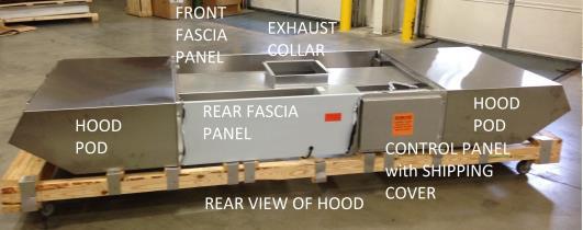
4 System Overview Parts Identification 4


5 ITEMS SHIPPED INSIDE CONTROL PANEL 5
6 6

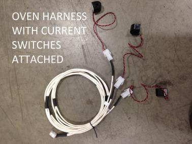
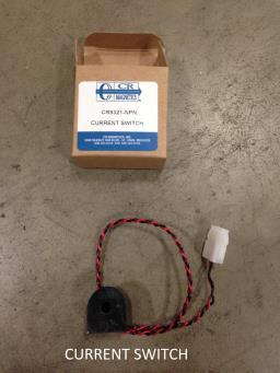
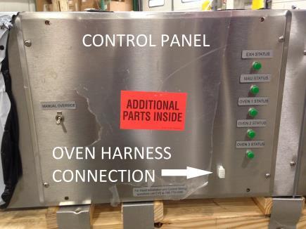
7 Model MM1 INSTALLATION INSTRUCTIONS Suggested Sequence of Assembly 1) Uncrate hood and side skirts (if side skirts were ordered). Inspect the crating carefully. If there are signs of damage, call the freight carrier before uncrating the units. Uncrate the units carefully. ** Important note ** Do not leave units out in the weather for an extended time period. The protective PVC covering around the hood will become very difficult to remove if left exposed to the weather conditions for a long period of time. The hood will be hung from the ceiling support structure using ½ all thread rods and ½ - 13 nuts. Use the hanging brackets that are attached to the back of each hood pod section, 4 places, to anchor the all thread rods at the hood. For structural calculations assume the hood assembly weighs 500 lbs. The fascia panels between the pods are removable to facilitate assembly. Removing the front panel will allow easier access to the top of the hood and the ductwork assembly. Additional parts are shipped inside the control panel. Remove the shipping cover that protects the control panel face by removing the four screws that hold it in place. Save the four screws but the shipping cover may be discarded. Remove the four additional screws that hold the control panel face and inside you will find the oven wiring harness with an 8 pin connector on one end and three 2 pin connectors on the other end, three current switches in boxes and a wiring diagram in a packing list envelope. Do not lose these parts found inside the control panel; they are very important to the operation of the MM1 hood. The control panel will be replaced using all 8 screws after all field wiring is completed. 7

8 2. Add the oven wiring harness and current switches to interface between the oven s blower control boxes (one per oven deck) and the hood control panel. The harness interconnects each oven deck with the control panel on the MM1 hood. Adding this harness is easier to accomplish before the oven and hood are located near a wall or other obstruction that would complicate access to the blower control boxes. Oven Wiring Harness Installation Instructions (8 pin Connector) A. Ensure the power to the oven is disconnected prior to wiring the control panel and oven. B. Locate the control panel at the exhaust hood and wiring diagram for the system. Review the wiring diagram and all instructions prior to beginning the process. C. Install current switches on blower fan as shown in photos below. Locations vary among ovens; examples are shown for the 360G and 570/670. Remove necessary shrouding to access the blower fan wiring. The wire to the motor should be temporarily disconnected to allow the wire to pass through the provided current switch. After insertion of the wire through the switch, replace the wire to the terminal. Route the current switch wiring in such a manner that it is in a safe position away from any moving parts using zip ties as necessary and ensure that the Molex connector is easily accessible for connection. See examples below. Installation of Current Switch on 360G 8


9 Installation of Current Switch on 570/670 Alternate Installation of Current Switch on 570/670, wires routed into electrical access panel 9

10 Alternate 570/670 Installation of current switch D. Locate the wiring harness for connection between the oven and control panel. The harness consists of 3 pairs of cable to connect to each deck for operation status. For single and triple stack ovens, the remaining pairs will not be used and are to be stored in a neat, safe fashion in the lowest oven deck. E. It will be necessary to drill holes as shown in the photos below to allow for harness routing. Install grommets to avoid chafing of wires. Holes should 7/8 diameter to allow grommet insertion. Locations shown are approximate - red circles indicate hole location, yellow dashed line indicates proposed harness routing. Installed harness examples are shown as well. Note: On the 570/670 ovens if the wires are routed through the electrical access panel drilling the hole can be avoided. If wires are routed in this fashion ensure they are not pinched in any of the doors. See the alternate 570/670 examples below. 10


11 To Control Panel 360G Harness Routing, 2 Deck Example 360G Harness Installation Example 11


12 To Control Panel 670 Harness Routing, 3 Deck Example 670 Harness Installation Example 12


13 Alternate 570/670 Install Example with wires secured to thermostat line Alternate 570/670 Install Example Avoid attaching adhesive pads directly to areas that get hot during cooking. F. The 8 pin connector should be positioned near the control panel location with sufficient slack to allow for connection to the panel. Secure with fastener mount cable holders as necessary, see photo below. 13


14 Cable Holder Installation with Self Tapping Screw Example G. Route the 3 wire pairs from the harness along the paths shown and down into the first oven deck control cabinet. Each pair will be labeled to indicate appropriate oven deck. Locate Deck 1 2-pin connection and connect to the current switch. Ensure the all wires are safely installed using fastener mount cable holders and zip ties as necessary, see photo below. Current Switch Connection to Wiring Harness H. Repeat the process for the remaining oven decks. I. When an extra connection is present, safely store in the lowest cabinet, see photo below. The harness is designed to accommodate a triple stack oven. 14
 Carefully position oven/hood combination in its final location. 4) Hang hood from ceiling support structure with all thread support rods (page 3).")
15 Extra Plug Stored in Lowest Oven Cavity Example J. Upon installation of the harness and current switches, connect the 8 pin connection of the oven harness to the mating connector on the control panel. 3) Carefully position oven/hood combination in its final location. 4) Hang hood from ceiling support structure with all thread support rods (page 3). Check fit of side skirts to hood before completing attachment. 5) Assemble side skirts to oven/hood (page 16). Side skirts, when desired, may be installed on both pods or are sometimes only required on the intake end of the oven. See the job specific submittal drawings or cut sheets for guidance on the locations and number of the side skirts. Side skirts are installed, if desired, by fastening the upper edges of the side skirt to the lower edges of the hood pod end walls where holes are provided for this purpose. Plastic knob fasteners are included to attach the top of the side skirt to the bottom edge of the hood. Tabs are provided along the side skirt flange which runs down the oven body which allows the side skirt to be attached to the oven at predetermined points. These points are places where accessories are already fastened to the oven. Remove the screws holding the accessories in place and locate the side skirt tabs over the screw holes. The screw(s) are then reinstalled through the slotted tabs, and tightened to hold the side skirt in position. The rear side skirt may have holes to allow the photocell sensor to operate through the side skirt. Align these holes with the photocell feature when installing the rear side skirt. If the side skirts were ordered as an option but will not be used a jumper wire in the control panel must be removed from between terminals 1 and 2. Please see details; item seven on page 26 and wiring diagram page

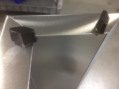
16 Side Skirt Attachment Side Skirt Knobs 16
17 17
18 6) Assemble ductwork. The MM1 hood is ducted to the exhaust fan with NFPA 96 compliant ductwork. The hood is fabricated with a 14 X 14 exhaust collar. When the hood is used with 18

19 a triple stack oven the exhaust duct should be 14 X 14 to the exhaust fan. When the hood is used with a single or double stack oven the exhaust duct should be 11.5 X 11.5 to the exhaust fan. A transition from the 14 X 14 exhaust collar to 11.5 X 11.5 exhaust duct is included to make the connection to the exhaust ductwork. The exhaust collar and the transition have 1 flanges to facilitate connection to the exhaust ductwork. All duct connections must be 100% liquid tight welded per NFPA 96 requirements. The MM1 hood may also be connected to Metal Fab pre-engineered exhaust ducting. The hood would then be ordered with a 14 diameter round exhaust collar attached to the hood and comes with a 14 diameter by 9 tall round extension for the duct (Metal Fab part no. 14PSW9) and duct connector (Metal Fab part no. 14RHC, called a flange band in the following instructions) and a tube of caulk (P080 sealant) which is used in the assembly of the duct sections. Appendix 2 is an instruction sheet from Metal Fab which describes the assembly of the duct sections. These instructions must be followed carefully and completely. 7) Replace fascia panels if they have been removed. 8) Complete Ansul installation (page 22, Fire Suppression System) if required. A. Locate the hood control panel and remove and discard the shipping cover (keep the screws) and remove the control panel face plate. The control panel is located at the rear of the hood assembly, recessed into the rear fascia panel between the hood pods, see photo below. Control Panel Locations Wiring harness and Current switches shipped Inside Control Panel B. Field wire terminals F9A and F10 to an open set (when Ansul fire suppression system is cocked) of dry contacts on one of the Ansul system micro switches. The Ansul micro switches are found in the Ansul Automan Regulated Release assembly. 19

20 The contacts will close when the system discharges. This will send a signal to the control panel that the fire suppression system has actuated. Fire suppression systems may not be required in some jurisdictions. Skip this step if no fire suppression system for the ovens is in place. C. Terminals M98 and M99 are a normally open dry contact that must be field wired to complete a start circuit for a Make Up Air fan, if one is present. The dry contact (CR1) will close when a signal is sent to start the exhaust fan. Maximum voltage for this circuit is 24 volts. The control panel will close the normally open contacts of the 24 volt Control Relay 1 (located in the control panel) to which terminals M98 and M99 are connected, when the exhaust fan turns on. This circuit is optional dependent upon makeup air unit configuration. Please refer to site drawings to determine if required. The field wiring from Terminal Strip contacts M98 and M99 to the make up air start/stop contactor shall be 2 strands and 18 gauge minimum. D. Field wire terminals E34, E35 and SH (shield) to the exhaust fan control box on the exhaust fan. The wire from terminal E34 connects to the 0-10V termination on the exhaust fan control box, the wire from terminal E35 connects to the Common termination. At the exhaust fan, 0-10VDC and Common are noted as shown in the Exhaust Fan Control photo below. Terminate the wire shield to a chassis ground at the control panel. Suggested field installed connection for the exhaust fan is 2 strand, 18 gauge minimum, shielded, plenum rated cable. Terminal Strip 20

21 Exhaust Fan Control 21
22 9) Connect hood to 120V building power source. Connect a three wire 120V, 15A circuit to terminals L (Line), N (Neutral) and G (Ground) in the Power Supply Box. 10) Commission system (starting on page 25). Make sure grease filters and grease cups are installed in place before start-up. 11) Check airflow balance in store, and perform final inspection (page 26). For Installation and Control Wiring questions: call EVS at Downloadable manuals may be found at FIRE SUPPRESSION SYSTEM The MM1 hood may be ordered pre-piped with a fire suppression system. Local codes or a desire for enhanced fire safety may dictate the inclusion of fire protection in the hood. The hood, if ordered pre-piped, will come with the detector bracket and fire protection nozzles installed in the exhaust plenum of both hood pods to cover the requirements of the duct protection and exhaust plenum protection. The local Ansul fire system installer must supply the distribution piping, Ansul Automan and suppressant tanks, detector conduit and wire rope runs, fusible links, remote pull station, Ansulex liquid fire suppressant and all other supplies to complete the fire system installation. If appliance protection is required the local Ansul installer must also design and install the distribution piping and nozzles for this requirement. This work must be performed by the Ansul system installer. The side skirts on the rear of the hood require notches to be cut or holes to be punched to allow access for the appliance protection distribution piping. Notches would be used if the side skirts are to be removed for cleaning later. The illustrations below depict the typical layout for an MM1 hood fire system. The prepipe components supplied by Halton are shown in solid lines and the components supplied by others are shown in dashed lines. The complete fire system must satisfy the requirements of the National Fire Protection Association (NFPA), Underwriters Laboratories Standard 300 and all local codes and Authorities Having Jurisdiction. Please note: Maintain all clearances necessary for access, maintenance and cleaning when the oven is positioned for final assembly and installation of the fire suppression system. 22
23 MM1 Typical Fire Suppression System Isometric View 23
24 MM1 Typical Fire Suppression System Schematic 24

25 MM1 Field Commissioning Instructions Operation Notes 1. The Hood Control Panel is configured in such a manner that exhaust fan and makeup air unit will be on when any combination of ovens are powered. 2. In the event of a fire, the make up air fan start/stop signal will switch to off and exhaust fan will go to full speed. 3. When the manual override is activated, the exhaust fan will operate at full speed. Commissioning 1. Ensure that the oven wiring harness is installed, all field connections are made and power is applied to the control panel, exhaust fan and oven. 2. Locate the status indicator lights on the control panel face, see photo below. Control Panel Face 3. Turn on the top oven deck and verify that the Exhaust Fan, the Make Up Air and the Top Deck (Oven 1 Status) lights are illuminated. See the status designations in photo below. 25

26 Status Designation on Control Panel 4. Verify that the exhaust fan and the makeup air fan functions as they are intended to. 5. Repeat the process for the other oven decks. 6. When fire protection is required, consult with the Authority Having Jurisdiction on the required performance test. 7. If side skirts were ordered as an option but will not be used a jumper wire in the control panel circuitry must be removed. Remove the front cover of the control panel. Remove the wire jumper between terminals 1 and 2. This will initiate an override setting that will change the default exhaust fan airflows to a higher airflow setting for each of the three oven deck airflows. The higher airflows are necessary if the side skirts are not used. 26
27 AIR BALANCE 1) After installation is complete, it will be necessary to check and balance the airflows for the building. a. Note: Adjustments to the exhaust fan should not be made without consulting EVS. The control system varies the exhaust flow based on the number of decks in operation as determined by inputs from the oven wiring harness and T.A.B. Port. 2) To ensure proper hood performance, locate all makeup and supply air diffusers a minimum of 2 feet away from the exhaust hood perimeter. 3) To ensure that proper air balance is maintained, the makeup air unit shall be interlocked with the exhaust fan operation. a. Note: When a fire suppression system is installed, the makeup air unit is configured to be OFF in the event of a fire while the exhaust fan is to run at full design airflow. 4) After the system has been placed into service and the balancing of airflows has been accomplished, a final inspection should be made. Check for unusual noises, excess exhaust or supply rates and general operation of the system. HOOD MAINTENANCE 1) Clean the hood pods inside and out as needed with mild soap and water. Never use harsh or abrasive cleaners on Stainless Steel or Painted surfaces. 2) Clean the hoods grease filters and grease cups daily, first washing by hand, and then placing them into a dishwasher for cleaning or by steam cleaning them. Please Note: Handle the Grease filters carefully Standard Equipment 4 Aluminum Filters Exhaust Hood is Listed per UL710 Exposed Surfaces are 430 Stainless Steel Optional Equipment Side Skirts (Painted is Optional) Front Eyebrow Section Cool Front Modified End Panels 27
28 PARTS LIST Filter 12 x 16 Aluminum Baffle Halton part number Filter - 12 x 20 Aluminum Baffle Halton part number x 14 to 11.5 x 11.5 transition Halton part number Duct Collar Extension 14PSW9 (3AO) (Round Duct) Halton part number Collar Connector 14PICRHC (3AO) (Round Duct) Halton part number
29 Wiring Diagram 29
30 Wiring Diagram Detail Oven Wiring Harness, 8 Pin Connector 30
31 Wiring Diagram Detail Field wiring close up 31
32 Appendix 2 Pre-Fab Duct Installation 38
 MUST BE BE FIELD INSTALLED FROM CONTROL PANEL TO THE EXHAUST FAN AND TERMINATED AT BOTH ENDS.")
33 0-10VDC Common SHIELD PRESSURE TRANSMITTER 0-0.5"WC +24DC -24DC NOTE: 120V/1PH REQUIRED FOR CONTROL PANEL. LOW VOLTAGE WIRING (0-10VDC PLUS SHIELD) MUST BE BE FIELD INSTALLED FROM CONTROL PANEL TO THE EXHAUST FAN AND TERMINATED AT BOTH ENDS. 2 STRANDS, 18 GAUGE MINIMUM SHIELDED, PLENUM RATED CABLE IS SUGGESTED. MM1 EXHAUST HOOD CONSTRUCTED OF 18 GA. 430 STAINLESS STEEL WHERE EXPOSED INCLUDES (2) 12X16 AND (2) 12X20 ALUMINUM BAFFLE STYLE GREASE FILTERS LISTED PER UL710 XRUD-141-VG EXHAUST FAN ALUMINUM HOUSING BACKWARD INCLINED ALUMINUM WHEEL ALUMINUM CURB CAP WITH PRE-PUNCHED MOUNTING HOLES DRAIN TROUGH MOTOR ISOLATED ON SHOCK MOUNTS CORROSION RESISTANT FASTENERS Exhaust Duct 16.0 SQ 18.5 SQ Suggested Roof Opening TOP VIEW 28.9 Dia Hinged Base Flat Roof Curb ANSUL FRONT VIEW EQUIPMENT SCHEDULE Direct Drive Upblast Centrifugal Roof Exhaust Fan MARK: EF-875 SP Accurex Volume Operating Weight Motor Information Qty Total SP FRPM Model (CFM) Power (hp) (Lb.) (in wg) Size (hp) V/C/P Encl: Motor Windings RPM FLA 1 1 XRUD-141-VG 875 1, /60/1 OP UL/cUL 762 Listed - "Power Ventilators for Rest. Exh. Appliances" Switch, NEMA-3R, Toggle, Junction Box Mounted & Wired Hinged Base (Attached) Curb Seal (Attached) Grease Trap (PN ) OPTIONS AND ACCESSORIES ISOMETRIC VIEW GPF ROOF CURB WELDED 18 GA. GALVANIZED CONSTRUCTION ROOF OPENING - THE MAXIMUM ROOF OPENING DIMENSION SHOULD NOT BE GREATER THAN THE ACTUAL TOP OUTSIDE DIMENSION MINUS 2". THE ROOF OPENING MAY NOT BE THE STRUCTURAL OPENING DIMENSION. NOTE: CONTROL PANEL ON REAR OF OVEN APPROXIMATELY 68" FROM WALL TO FRONT OF HOOD INSTALLATION SUSPEND HOOD 1/2" ABOVE OVEN HEIGHT USING HANGER RODS. MOVE OVEN INTO PLACE. MAKE FINAL EXHAUST DUCT CONNECTIONS. GENERAL NOTES: 1. DO NOT SCALE DRAWING, USE DIMENSIONS AS INDICATED. 2. IT IS THE RESPONSIBILITY OF THE INSTALLING CONTRACTOR TO OBTAIN ALL PERMITS AND APPROVALS FROM ALL STATE AND LOCAL OFFICIALS PRIOR TO PROCEEDING WITH INSTALLATION. THESE DRAWINGS ARE TO SERVE AS BASIC DESIGN ONLY AND ANY STATE OR LOCAL ORDINANCE WHICH IS MORE RESTRICTIVE SHALL PREVAIL. 3. IT IS THE RESPONSIBILITY OF THE INSTALLING CONTRACTOR TO CHECK BUILDING ACCESS AND FIELD CONDITIONS TO ALLOW FOR ADEQUATE CLEARANCES FOR THE EQUIPMENT TO BE BROUGHT IN AND INSTALLED. 4. AIR INTAKES MUST BE NO CLOSER THAN 10 FEET FROM ANY EXHAUST OR VENT OUTLET. 5. EXHAUST DUCTWORK TO BE CONSTRUCTED OF 16 GA. B.I. OR 18 GA STAINLESS STEEL AND CONTINUOUSLY WELDED. DUCT CLEAN OUTS SHALL BE PROVIDED AT EVERY CHANGE IN DIRECTION. INSTALLING CONTRACTOR SHALL VERIFY ANY REQUIREMENTS FOR INSULATION OF THE EXHAUST DUCT. 6. EXHAUST FAN(S) SHALL EXTEND A MINIMUM OF 40 INCHES ABOVE ROOF SURFACE AND BE PROPERLY FLASHED TO ADJOINING MATERIAL. 7. VERIFY ALL STRUCTURAL LOADS WITH ARCHITECT OF RECORD. 8. THESE DRAWINGS ARE TO SERVE AS A BASIC DESIGN ONLY AND ANY STATE OR LOCAL ORDINANCE WHICH IS MORE RESTRICTIVE SHALL PREVAIL. 9. IT IS THE RESPONSIBILITY OF THE OWNER/ARCHITECT TO ENSURE THE HOOD CLEARANCE FROM COMBUSTIBLES (AND NON OR LIMITED COMBUSTIBLES) IS IN COMPLIANCE WITH THE LATEST EDITION OF THE NATIONAL FIRE PROTECTION ASSOCIATION BULLETIN # FIRE SUPPRESSION SYSTEM, IF REQUIRED, PROVIDED AND INSTALLED BY OTHERS. ROOF DECK EXHAUST DUCT INSULATION BY OTHERS IF REQUIRED FIELD DUCTWORK BY OTHERS COLLAR FACTORY MOUNTED HOOD TRANSITION DUCT PROJECT NAME: MIDDLEBY MARSHALL PS-570 / PS-670 DOUBLE DECK 1419 S. MILFORD ROAD HIGHLAND, MI P: F:
34 39
35 WARRANTY Halton Company warrants all MM1 hoods for a period of 12 months from date of shipment to be without defects in workmanship and material. Omissions or defects will be re- placed or repaired at Halton s option. Halton will not accept labor charges without prior approval. GENERAL INSTALLATION Upon receipt of the Halton hood, inspect it immediately for any shipping damage and notify carrier immediately if damage is found. Halton will not accept responsibility for any shipping damage, but will assist with getting a claim filed if needed. There are no instructions contained within this manual for installation or maintenance of fan packages. See appropriate manufacturer s manual for detailed instructions. It is the responsibility of the installing contractor to see that the system installation is completed in accordance with the project plans and specifications and that it meets all specific requirements of local code officials. The local authority having jurisdiction could overrule some of the installation details written in this manual. The installation shall be in accordance with NFPA-96. All electrical systems shall be installed following local and national codes. It is very important that the system be turned over to the owner in the best condition possible. The owner and/or operator should be instructed in the proper operation, care and maintenance of the system. If questions or complications should arise during the installation of the Halton hood that cannot be solved using the instructions, please contact EVS at For Warranty questions or issues please contact the Halton office at Continuous product improvement is a Halton policy, therefore specifications and design are subject to change without notice. For Warranty issues: 101 Industrial Drive Scottsville, KY (800-4-HALTON) For Installation and Control Wiring questions: call EVS at
Operators Manual for JES-HD
 Operators Manual for JES-HD Heavy Duty Jet Extraction System Manual provides Operation, Maintenance and Service Instructions Heavy Duty Jet Extraction System Model: JES-HD Form#: OM038_JES-HD_Jet_Extraction_System
KVR Capture Jet. KVR- Capture Jet Round Island Hood with Perimeter Jets. Round Island Hood with Perimeter Jets
 KVR Capture Jet Round Island Hood with Perimeter Jets The KVR Round Island Capture Jet hood with perimeter jets is a highly efficient kitchen ventilation hood that removes contaminated air and excess heat
KVM KVM. Capture Jet Hybrid Backshelf Hood. Capture Jet TM Hybrid Backshelf Hood
 Capture Jet Hybrid Backshelf Hood The hybrid backshelf model of Capture Jet hood is a highly efficient kitchen ventilation hood that removes contaminated air and excess heat emitted by cooking equipment,
Model ND-2 Specification
 Model ND-2 Specification The model ND-2 is an exhaust only canopy hood rated for all types of cooking equipment. The hood shall have the size, shape and performance specified on drawings. Construction
KVL-P with Plate Shelf
 The model of Capture Jet TM hood is a highly efficient kitchen ventilation hood that removes contaminated air and excess heat emitted by cooking equipment, helping to provide a comfortable and clean environment.
Installation, Operation and Maintenance Manual
 Commercial Kitchen Hood Installation, Operation and Maintenance Manual www.fastkitchenhood.com General Information Prior to installing the stainless steel ventilation hood, the installing contractor should
Installation Manual for Ecology
 Installation Manual for Ecology Manual provides Installation Instructions UL 1978 Standard for Grease Ducts, UL 710, Exhaust Hoods for Commercial Cooking Equipment, ULC-S647-05 and/or UL197 EcoloAir Unit
Direct Gas-Fired Heating
 Direct Gas-Fired Heating Model DG 800 to 15,000 cfm Up to 1,600,000 BTU/hr Optional Evaporative Cooling January 2005 PRODUCT FEATURES Model DG Direct Gas-Fired Make-Up Air Unit The Greenheck model DG is
INSTALLATION VARIABLE FREQUENCY DRIVE THREE PHASE ALX SERIES SPUN ALUMINUM EXHAUSTERS
 SPUN ALUMINUM EXHAUSTER OPERATION INSTRUCTIONS AND PARTS MANUAL READ AND SAVE THESE INSTRUCTIONS The purpose of this manual is to aid in the proper installation and operation of the blowers. These instructions
CENTRIFUGAL UPBLAST ROOF EXHAUSTERS Model VRBK
 CENTRIFUGAL UPBLAST ROOF EXHAUSTERS Model VRBK CENTRIFUGAL UPBLAST ROOF EXHAUSTERS COMMERCIAL KITCHEN APPLICATIONS Belt Driven Model VRBK DESIGNED AND ENGINEERED TO MEET INDUSTRY NEEDS The Carnes Company
Tubular Centrifugal Fans
 Tubular Centrifugal Fans Model TCB Inline - Horizontal or Vertical Roof Upblast and Roof Supply March 2007 Tubular Centrifugal Fans The TCB series of inline centrifugal fans is designed for ducted inline,
Charcoal Filter Installation NOTE: The charcoal filters are preinstalled if you purchased the range hood with re-circulating kit from us. 1. Remove st
 Venting Methods This range hood is factory set for venting through the roof or wall. For non-vented (re-circulating) installations, see Ductless Conversion on Page 7. Vent work can terminate either through
Installation, Operation and Maintenance Manual
 Document 481038 Model PVF and PVG Indirect Gas-Fired Heat Modules Indirect Gas-Fired Furnaces Installation, Operation and Maintenance Manual Please read and save these instructions for future reference.
Filtered Kitchen Supply Packaged Ventilator
 Filtered Kitchen Supply Packaged Ventilator Page Introduction........................................... 2 Information............................................ 3 Specifications and Dimension Data KD................................................
READ AND SAVE THESE INSTRUCTIONS
 READ AND SAVE THESE INSTRUCTIONS Part #469003 Model Vektor -H Installation Operation and Maintenance Manual for Vektor-H Laboratory Exhaust System Receiving Greenheck model Vektor-H fans are thoroughly
Installation, Operation and Maintenance Manual
 Document 481038 Model PVF(-H) and PVG Indirect Gas-Fired Heat Modules Indirect Gas-Fired Furnaces Installation, Operation and Maintenance Manual Please read and save these instructions for future reference.
INSTALLATION MANUAL. Melink Corporation (513) Revision
 Revision") INSTALLATION MANUAL Revision 130711 Table of Contents Step Installation Contractor Page 1 Install System Controller Electrical 4 2 Install Variable Frequency Drive Electrical 6 3 Install Touchpad Mechanical
INSTALLATION MANUAL Revision 130711 Table of Contents Step Installation Contractor Page 1 Install System Controller Electrical 4 2 Install Variable Frequency Drive Electrical 6 3 Install Touchpad Mechanical
Electrical Control Panel
 Electrical Control Panel Kitchen Ventilation Control System Installation and Operations Manual Photo to Come FOR MODELS: ECP Striving for Excellence STREIVOR.COM Table of Contents General Information Pre-Installation
Modified Downdraft Paint Booth Nut and Bolt Assembly Pre-Punched Panel Flanges
 Phone: 800-348-1097 www.aeipaintbooths.com Modified Downdraft Paint Booth Nut and Bolt Assembly Pre-Punched Panel Flanges Thank you for the opportunity to work with you on your paint booth project. Below
INSTALLATION INSTRUCTIONS UNDER CABINET HOOD
 Read and Save These Instructions All Hoods Must Be Installed By A Qualified Installer INSTALLATION INSTRUCTIONS UNDER CABINET HOOD Read All Instructions Thoroughly Before Beginning Installation WARNING
Roof Upblast and Sidewall Exhaust
 XRUB, XRUD, XSEB, XSED, and XRUBS models are listed for electrical (UL/C-UL US 0) File no. E000 and for grease removal (UL/C-UL US ) File no. MH. Accurex, LLC certifies model XRUB, XRUD, XSEB, XSED, and
Operations & Maintenance Manual DFH-1000 DUCTLESS FUME HOOD
 Operations & Maintenance Manual DFH-1000 DUCTLESS FUME HOOD ----------------------------------------------------------------We Make Clean Air----------------------------------------------------------------
INSTALLATION INSTRUCTIONS ISLAND RANGE HOOD
 Read and Save These Instructions All Hoods Must Be Installed By A Qualified Installer INSTALLATION INSTRUCTIONS ISLAND RANGE HOOD Read All Instructions Thoroughly Before Beginning Installation WARNING
INSTALLATION INSTRUCTIONS UNDER CABINET HOOD
 Read and Save These Instructions All Hoods Must Be Installed By A Qualified Installer INSTALLATION INSTRUCTIONS UNDER CABINET HOOD Read All Instructions Thoroughly Before Beginning Installation WARNING
INSTALLATION INSTRUCTIONS ZTH WALL MOUNT HOOD
 Read and Save These Instructions All Hoods Must Be Installed By A Qualified Installer INSTALLATION INSTRUCTIONS ZTH WALL MOUNT HOOD Read All Instructions Thoroughly Before Beginning Installation WARNING
Installation Instructions
 Installation Instructions Speedcook Oven Read carefully. Keep these Instructions. INSTALLATION INSTRUCTIONS Electrical Requirements Product rating is 240/208 volts AC, 60 Hertz, 30 amps and 6.5 kilowatts.
Roof Upblast and Sidewall Exhaust
 XRUB, XRUD, XSEB, XSED, and XRUBS models are listed for electrical (UL/C-UL US 705) File no. E40001 and for grease removal (UL/C-UL US 762) File no. MH11745. Accurex, LLC certifies model XRUB, XRUD, XSEB,
INSTALLATION INSTRUCTIONS EUROLINE/EUROLINE PRO WALL MOUNT HOOD
 WARNING - TO REDUCE THE RISK OF FIRE, USE ONLY METAL DUCTWORK C U L R Read and Save These Instructions All Hoods Must Be Installed By A Qualified Installer INSTALLATION INSTRUCTIONS EUROLINE/EUROLINE PRO
Model 8144NC Fresh Air Ventilator
 Model 8144NC Fresh Air Ventilator Installation and Operating Instructions MOUNTING BRACKETS WIRE ENTRY LOCATION INTEGRAL PRESSURE PORTS (PORT ON INLET SIDE NOT SHOWN) OVAL OUTLET COLLAR FOR 6" DIAMETER
Commercial Kitchen Hoods Installation, Operation, and Maintenance Manual
 Commercial Kitchen Hoods Installation, Operation, and Maintenance Manual RECEIVING AND INSPECTION Upon receiving unit, check for any interior and exterior damage, and if found, report it immediately to
MODELS TSX AND TSX-S SINGLE DUCT ROUND AIR TERMINALS
 MODELS TSX AND TSX-S SINGLE DUCT ROUND AIR TERMINALS INSTALLATION OPERATION & MAINTENANCE New Release Form 130.13-NOM4 (908) In conjunction with the use of these instructions, obtain and refer to the construction,
INSTALLATION INSTRUCTIONS ISLAND RANGE HOOD
 Read and Save These Instructions All Hoods Must Be Installed By A Qualified Installer INSTALLATION INSTRUCTIONS ISLAND RANGE HOOD Read All Instructions Thoroughly Before Beginning Installation WARNING
Thirteen (13) UL listed fluorescent fixtures per booth will supply illumination.
 UL listed fluorescent fixtures per booth will supply illumination.") Quoted as per your request: two (2) Non-Pressurized, Drive-Thru, Full Down Draft, Paint Booth model: TDD-16-16-20-DT with interior working dimensions of 16-0 wide X 16-0 tall X 20-0 long. Overall dimensions
Quoted as per your request: two (2) Non-Pressurized, Drive-Thru, Full Down Draft, Paint Booth model: TDD-16-16-20-DT with interior working dimensions of 16-0 wide X 16-0 tall X 20-0 long. Overall dimensions
MODELS STXD & STXDe DIRECT DRIVE CENTRIFUGAL ROOF EXHAUSTERS
 MODELS & e DIRECT DRIVE CENTRIFUGAL ROOF EXHAUSTERS MODEL DIRECT DRIVE CENTRIFUGAL ROOF EXHAUSTER MODEL FEATURES Exhaust air up to 4,780 CFM in high static pressure applications up to 1-1/2 w.g. Attractive
READ AND SAVE THESE INSTRUCTIONS. Air Boss MP600M Vertical Air Flow Mist Precipitator Industrial Applications. TRION
 READ AND SAVE THESE INSTRUCTIONS Vertical Air Flow Mist Precipitator Industrial Applications TRION Vertical Air Flow Mist Precipitator for Industrial Applications Table of Contents Design...2 Installation...2
I N ST R UC T I ON MODEL HVH23 STAND-ALONE EXHAUST HOOD MODELS. FORM (May 2000) S. RIDGE AVENUE TROY, OHIO
 S. RIDGE AVENUE TROY, OHIO") I N ST R UC T I ON MODEL HVH23 STAND-ALONE EXHAUST HOOD S MODELS HVH23 ML-126808 701 S. RIDGE AVENUE TROY, OHIO 45374-0001 937 332-3000 www.hobartcorp.com 1 FORM 34503 (May 2000) R Ansul Fire Supression
I N ST R UC T I ON MODEL HVH23 STAND-ALONE EXHAUST HOOD S MODELS HVH23 ML-126808 701 S. RIDGE AVENUE TROY, OHIO 45374-0001 937 332-3000 www.hobartcorp.com 1 FORM 34503 (May 2000) R Ansul Fire Supression
SECTION AXIAL HVAC FANS
 SECTION 233413 - AXIAL HVAC FANS 1. PART 1 GENERAL 1.1. RELATED DOCUMENTS A. Drawings and general provisions of the Contract, including General and Supplementary Conditions and Division 01 Specification
INSTALLATION INSTRUCTIONS EUROLINE/EUROLINE PRO WALL MOUNT HOOD
 Read and Save These Instructions All Hoods Must Be Installed By A Qualified Installer INSTALLATION INSTRUCTIONS EUROLINE/EUROLINE PRO WALL MOUNT HOOD Read All Instructions Thoroughly Before Beginning Installation
Commercial Kitchen Hoods Installation, Operation, and Maintenance Manual
 Commercial Kitchen Hoods Installation, Operation, and Maintenance Manual RECEIVING AND INSPECTION Upon receiving unit, check for any interior and exterior damage, and if found, report it immediately to
INSTALLATION INSTRUCTIONS WALL MOUNT RANGE HOOD WITH M600 OR M1200 BLOWER
 WARNING - TO REDUCE THE RISK OF FIRE, USE ONLY METAL DUCTWORK C U L R Read and Save These Instructions All Hoods Must Be Installed By A Qualified Installer INSTALLATION INSTRUCTIONS WALL MOUNT RANGE HOOD
INSTALLATION INSTRUCTIONS WALL MOUNT RANGE HOOD WITH M600 OR M1200 BLOWER
 WARNING - TO REDUCE THE RISK OF FIRE, USE ONLY METAL DUCTWORK C U L R Read and Save These Instructions All Hoods Must Be Installed By A Qualified Installer INSTALLATION INSTRUCTIONS WALL MOUNT RANGE HOOD
Utility Distribution Systems Installation, Operation, and Maintenance Manual
 Utility Distribution Systems Installation, Operation, and Maintenance Manual RECEIVING AND INSPECTION Upon receiving unit, check for any interior and exterior damage, and if found, report it immediately
INSTALLATION INSTRUCTIONS WALL MOUNT HOOD
 Read and Save These Instructions All Hoods Must Be Installed By A Qualified Installer INSTALLATION INSTRUCTIONS WALL MOUNT HOOD Read All Instructions Thoroughly Before Beginning Installation WARNING -
SPUN ALUMINUM POWER ROOF AND WALL VENTILATORS
 BULLETIN 0 January 007 SPUN ALUMINUM POWER ROOF AND WALL VENTILATORS TYPE ACX / ACXD TYPE ATD / ATDR / ATDW / ATDWR TYPE ATB / ATBR / AWX / AWXR Model ACX Model ATB Model ACXD Model ATDR Model AWX Centrifugal
TGIF-3. Indirect Fired Heating Systems. Technical Guide for: IF Indoor Installations. IFW Outdoor Installations. Applied Air. Keeps You.
 TGIF-3 Indirect Fired Heating Systems Technical Guide for: IF Indoor Installations IFW Outdoor Installations Applied Air Keeps You Warm Indirect Fired Heating Systems Technical Guide In the business of
INSTALLATION INSTRUCTIONS EUROLINE/EUROLINE PRO WALL MOUNT HOOD
 WARNING - TO REDUCE THE RISK OF FIRE, USE ONLY METAL DUCTWORK C U L R Read and Save These Instructions All Hoods Must Be Installed By A Qualified Installer INSTALLATION INSTRUCTIONS EUROLINE/EUROLINE PRO
INSTALLATION INSTRUCTIONS AH12 WALL MOUNT HOOD
 Read and Save These Instructions All Hoods Must Be Installed By A Qualified Installer INSTALLATION INSTRUCTIONS AH12 WALL MOUNT HOOD Read All Instructions Thoroughly Before Beginning Installation WARNING
General Description. Product Specification. Document Digital Temperature Interlock
 Document 474751 Installation, Operation and Maintenance Manual Please read and save these instructions for future reference. Read carefully before attempting to assemble, install, operate or maintain the
Zoneflow Engineering Installation and Maintenance Manual
 Zoneflow Engineering Installation and Maintenance Manual Introduction The Cadexair ZoneFlow is designed to be installed in a commercial kitchen NFPA-96 central exhaust fan duct system up stream of each
INSTALLATION INSTRUCTIONS K-SERIES UNDER CABINET HOOD
 Read and Save These Instructions All Hoods Must Be Installed By A Qualified Installer INSTALLATION INSTRUCTIONS K-SERIES UNDER CABINET HOOD Read All Instructions Thoroughly Before Beginning Installation
INSTALLATION INSTRUCTIONS JDH/C2 DESIGNER SERIES WALL MOUNT HOOD
 WARNING - TO REDUCE THE RISK OF FIRE, USE ONLY METAL DUCTWORK C U L R Read and Save These Instructions All Hoods Must Be Installed By A Qualified Installer INSTALLATION INSTRUCTIONS JDH/C2 DESIGNER SERIES
Preparation Advanced Preparations: Be familiar with the controls of the range hood by reading through Range Hood Operations, Page 12. Place the range
 Electrical Requirements IMPORTANT: Observe all governing codes and ordinances. (Please consult with a qualified electrician for 220-Volt 50 Hz voltage) It is the customer s responsibility: To contact a
MODELS SGX AND SSX SINGLE DUCT ROUND AIR TERMINALS
 BY JOHNSON CONTROLS INSTALLATION OPERATION & MAINTENANCE MODELS SGX AND SSX SINGLE DUCT ROUND AIR TERMINALS New Release Form ET130.13-NOM4 (908) In conjunction with the use of these instructions, obtain
CSA CERTIFIED Conforms to UL 507
 Installation tion Instructions Please read and save these instructions! TURBO/MAXX12 Volt All Weather RV Ventilator Fans P/N 00-965001 Deluxe Model 1200T WITH THERMOSTAT P/N 00-965007 Standard Model 3550
INSTALLATION INSTRUCTIONS
 MiniCOREVentilator ENERGY RECOVERY CORE INSTALLATION INSTRUCTIONS MC500-1ERV JANUARY 10, 2018 SUPERSEDES: NONE INSTALLATION INSTRUCTIONS FOR MINICORE VENTILATOR (MCV) WITH FACTORY INSTALLED OPTIONS USED
INSTALLATION & OPERATION MANUAL. Fan Powered Terminals VAV TERMINALS. Redefine your comfort zone.
 INSTALLATION & OPERATION MANUAL Fan Powered Terminals VAV TERMINALS IOM FAN POWERED TERMINALS Receiving Inspection After unpacking the terminal, check it for shipping damage. If any shipping damage is
Installation, Operation and Maintenance Manual
 Document 458295 Automatic Fire Damper Installation, Operation and Maintenance Manual Please read and save these instructions for future reference. Read carefully before attempting to assemble, install,
MODEL TXD DIRECT DRIVE CENTRIFUGAL UPBLAST ROOF EXHAUSTER
 MEL TXD Model Features Exhaust air up to 3,400 CFM in high static pressure applications up to 1-1/4 w.g. Attractive spun aluminum exterior Direct drive units have low sound levels and quiet operation Non-overloading
Air Moving Solutions. low pressure mixed flow fans. QCLB QCLBR (Restaurant) QCLBSH (Smoke & Heat)
 QCLBSH (Smoke & Heat)") Air Moving Solutions. low pressure mixed flow fans QCLB QCLBR (Restaurant) QCLBSH (Smoke & Heat) BULLETIN 1070 February 2012 MixedFlowFans Models QCLB QCLBR QCLBSH Benefits of Mixed Flow Fans Twin City
Air Moving Solutions. low pressure mixed flow fans QCLB QCLBR (Restaurant) QCLBSH (Smoke & Heat) BULLETIN 1070 February 2012 MixedFlowFans Models QCLB QCLBR QCLBSH Benefits of Mixed Flow Fans Twin City
SECTION AIR TERMINAL UNITS
 SECTION 23 36 00 AIR TERMINAL UNITS PART 1 - GENERAL 1.1 SUMMARY A. Section includes constant volume terminal units, variable volume terminal units, dual duct terminal units, fan powered terminal units,
INSTALLATION INSTRUCTIONS EUROLINE/EUROLINE PRO ISLAND RANGE HOOD
 WARNING - TO REDUCE THE RISK OF FIRE, USE ONLY METAL DUCTWORK C U L R Read and Save These Instructions All Hoods Must Be Installed By A Qualified Installer INSTALLATION INSTRUCTIONS EUROLINE/EUROLINE PRO
B. Fabricate in accordance with ASHRAE handbooks and SMACNA duct manuals. A. Submit in accordance with Division-1 and Section
 SECTION 15910 DUCT ACCESSORIES PART 1 - GENERAL 1.01 RELATED DOCUMENTS A. Drawings and general provisions of Contract including General and Supplementary Conditions, Division-1 Specification Sections,
Electric Coil [Make-Up Air / Displacement Ventilation / Space Heating] System
![Electric Coil [Make-Up Air / Displacement Ventilation / Space Heating] System](/thumbs/89/99847795.jpg "Electric Coil [Make-Up Air / Displacement Ventilation / Space Heating] System") V-Series (rev. 08/17/10) Electric Coil [Make-Up Air / Displacement Ventilation / Space Heating] System Note: Optional items and/or items requiring a choice, are shown between brackets and/or parentheses
V-Series (rev. 08/17/10) Electric Coil [Make-Up Air / Displacement Ventilation / Space Heating] System Note: Optional items and/or items requiring a choice, are shown between brackets and/or parentheses
OPERATOR MANUAL IMPORTANT INFORMATION, KEEP FOR OPERATOR
 OPERATOR MANUAL IMPORTANT INFORMATION, KEEP FOR OPERATOR This manual provides information for: THIS MANUAL MUST BE RETAINED FOR FUTURE REFERENCE. READ, UNDERSTAND AND FOLLOW THE INSTRUCTIONS AND WARNINGS
650 Series Cargo Van Lift Mounting Instructions Ford Transit (Standard Roof) 2015-Present
 2015-Present") TOMMY GATE OWNER'S / OPERATOR'S MANUAL 650 Series 650 LB Capacity 650 Series Cargo Van Lift Mounting Instructions Ford Transit (Standard Roof) 2015-Present Installing the Base Plate 1. Examine the interior
TOMMY GATE OWNER'S / OPERATOR'S MANUAL 650 Series 650 LB Capacity 650 Series Cargo Van Lift Mounting Instructions Ford Transit (Standard Roof) 2015-Present Installing the Base Plate 1. Examine the interior
INSTALLATION INSTRUCTIONS CWUH9 WALL MOUNT HOOD
 Read and Save These Instructions All Hoods Must Be Installed By A Qualified Installer INSTALLATION INSTRUCTIONS CWUH9 WALL MOUNT HOOD Read All Instructions Thoroughly Before Beginning Installation WARNING
Twin City Fan & Blower
 Twin City Fan & Blower BULLETIN 405 April 2009 UPBLAST ROOF, WALL, & KITCHEN EXHAUSTERS TYPE DCRU / DCRUR / DCRW / DCRWR TYPE BCRU / BCRUR / BCRW / BCRWR TYPE BCRUSH (Smoke & Heat) Upblast Roof, Wall,
INSTALLATION INSTRUCTIONS JCH/C2 DESIGNER SERIES WALL MOUNT HOOD
 WARNING - TO REDUCE THE RISK OF FIRE, USE ONLY METAL DUCTWORK C U L R Read and Save These Instructions All Hoods Must Be Installed By A Qualified Installer INSTALLATION INSTRUCTIONS JCH/C2 DESIGNER SERIES
SECTION CENTRIFUGAL HVAC FANS
 SECTION 233416 - CENTRIFUGAL HVAC FANS 1. PART 1 GENERAL 1.1. RELATED DOCUMENTS A. Drawings and general provisions of the Contract, including General and Supplementary Conditions and Division 01 Specification
INSTALLATION INSTRUCTIONS CWEH6-K WALL MOUNT HOOD
 Read and Save These Instructions All Hoods Must Be Installed By A Qualified Installer INSTALLATION INSTRUCTIONS CWEH6-K WALL MOUNT HOOD Read All Instructions Thoroughly Before Beginning Installation WARNING
SECTION HVAC POWER VENTILATORS
 SECTION 233423 HVAC POWER VENTILATORS 1. PART 1 GENERAL 1.1. RELATED DOCUMENTS A. Drawings and general provisions of the Contract, including General and Supplementary Conditions and Division 01 Specification
Air Boss Model M3000. Industrial Air Cleaner READ AND SAVE THESE INSTRUCTIONS. TRION
 READ AND SAVE THESE INSTRUCTIONS Air Boss Industrial Air Cleaner TRION www.trioniaq.com Industrial Air Cleaner AIR BOSS M3000 TABLE OF CONTENTS Specifications...3 Principles of Operation...3 New Unit Inspection...3
TURNING AIR INTO SOLUTIONS. DIRECT DRIVE EXHAUST & SUPPLY PANEL FANS. Model TCPE
 TURNING AIR INTO SOLUTIONS. DIRECT DRIVE EXHAUST & SUPPLY PANEL FANS Model TCPE CATALOG 4800 February 2017 PANEL FANS Overview TCPE TCPE panel fans are direct drive panel fans designed for low static pressures.
MODEL NBRTD BELT DRIVE CENTRIFUGAL UPBLAST ROOF EXHAUSTER
 Model Features Exhaust air up to 6,817 CFM in high static pressure applications up to 3 Belt drives permit easy performance adjustments when needed Nonoverloading backward inclined wheel for efficiency
Electric. PN April Series Electric Oven
 Electric PN April 2013 Series Electric Oven E NOTICE: This Owner s Operating and Installation Manual should be given to the user. The operator of the oven should be familiar with the operation of the oven.
Tube Axial Inline Fans
 Tube Axial Inline Fans Models TDI & TBI-CA Level 3 with Cast Aluminum Propeller Direct & Belt Drive Clean Air or Fume Exhaust July 2011 Features Tube Axial Inline Fans Greenheck s tube axial fans are the
LOW PRESSURE MIXED FLOW FANS
 Twin City Fan INDUSTRIAL PROCESS AND COMMERCIAL VENTILATION SYSTEMS LOW PRESSURE MIXED FLOW FANS QCLB QCLBR QCLBSH CATALOG 1070 JANUARY 2017 MIXED FLOW FANS Models QCLB QCLBR QCLBSH QCLB (Horizontal) Benefits
TABLE OF CONTENTS SPECIFICATIONS 3 INSTALLATION 4. Direct Mount 4. Ducted Installations 5. Installing Plenum 5. Machine Mount Stand 5.
 TABLE OF CONTENTS PAGE SPECIFICATIONS 3 INSTALLATION 4 Direct Mount 4 Ducted Installations 5 Installing Plenum 5 Machine Mount Stand 5 Ceiling Mount 6 Pedestal Stand 7 Drain Installation 7 Electrical 8
CENTRIFUGAL UPBLAST ROOF EXHAUSTERS Models VUDK and VUBK
 CENTRIFUGAL UPBLAST ROOF EXHAUSTERS Models VUDK and VUBK CENTRIFUGAL UPBLAST ROOF EXHAUSTERS Direct and Belt Driven Models VUDK and VUBK DESIGNED AND ENGINEERED TO MEET INDUSTRY NEEDS The Carnes Company
INSTALLATION INSTRUCTIONS EUROLINE/EUROLINE PRO ISLAND RANGE HOOD
 Read and Save These Instructions All Hoods Must Be Installed By A Qualified Installer INSTALLATION INSTRUCTIONS EUROLINE/EUROLINE PRO ISLAND RANGE HOOD Read All Instructions Thoroughly Before Beginning
University of Delaware
 SECTION 23 36 00 _ SUMMARY PART 1 GENERAL 1.1 SUMMARY A. Section Includes: 1. Constant/Variable volume supply terminal units. 2. Fan powered terminal units. 3. Exhaust valves B. Related Sections: Section
Model Description Vac. Max rating Pedestal Only: 36 Utility Pedestal W/O Disconnect General Duty Series:
 MAPA Products MPD-XX / Pedestal Disconnect 30, 60, 100 amp February 2014 Pedestal Disconnect Installation Instructions Parts List MAPA Products Fusible Rainproof Pedestal Mounted Safety Switch provides
Installation Instructions
 Installation Instructions Over The Range Microwave Oven BEFORE YOU BEGIN (Read these instructions completely and carefully.) IMPORTANT IMPORTANT Save these instructions for local inspector s use. Observe
Installation, Operation and Maintenance Manual
 Document 479288 Installation, Operation and Maintenance Manual Please read and save these instructions for future reference. Read carefully before attempting to assemble, install, operate or maintain the
Model: G-143-VG. CAPS Z:\Carl\winjobs\Alley 111.gfcj Page 6 of 18
 Printed Date: 10/7/2014 Mark: EF-R04 Model: G-143-VG Direct Drive Centrifugal Roof Exhaust Fan Standard Construction Features: Model G Centrifugal Roof Exhaust Fans are direct drive. These fans are specifically
DW Series - Exhaust Only Wall Canopy
 DW Exhaust Only Wall Canopy Model DW A single shell non-compensating exhaust only wall hung canopy constructed of stainless steel where visible and aluminized steel in concealed locations. All external
Inline Fans [ 14 ] * UL is optional and must be specified.
![Inline Fans [ 14 ] * UL is optional and must be specified.](/thumbs/87/95740152.jpg "Inline Fans [ 14 ] * UL is optional and must be specified.") XTIF, XIB and XID models are listed for electrical (UL/C-UL US 705) File no. E40001. Model XTIF is available with the UL 762 Listing (Power Ventilators for Restaurant Exhaust Appliances). Accurex, LLC
XTIF, XIB and XID models are listed for electrical (UL/C-UL US 705) File no. E40001. Model XTIF is available with the UL 762 Listing (Power Ventilators for Restaurant Exhaust Appliances). Accurex, LLC
B. Base occupied space sound level estimates on ARI 885. C. Terminal heating coils shall conform to ARI 410.
 PART 1 - GENERAL 1.01 Purpose: A. This standard is intended to provide useful information to the Professional Service Provider (PSP) to establish a basis of design. The responsibility of the engineer is
MODEL TXD DIRECT DRIVE CENTRIFUGAL UPBLAST ROOF EXHAUSTER
 MEL TXD MEL FEATURES Exhaust air up to 3,400 CFM in high static pressure applications up to 1-1/4 w.g. Attractive spun aluminum exterior Direct drive units have low sound levels and quiet operation Non-overloading
Installation Instructions
 Installation Instructions MX3635-01 Rev. E Models HydraSwing 40s HydraSwing 40F 4,000 lb (1,814 kg) 10-15 seconds HydraSwing 40 4,000 lb (1,814 kg) 15-20 seconds HydraSwing 40 Twin 4,000 lb (1,814 kg)/leaf
Air Curtain. Installation, Operating and Maintenance Instructions
 Installation, Operating and Maintenance Instructions Save this manual for future reference. Air Curtain Model Numbers: ES026, ES036, ES042, ES048, ES060, ES072 READ THIS OWNER S MANUAL CAREFULLY BEFORE
INSTALLATION INSTRUCTIONS COMMERCIAL ROOM VENTILATORS WITH EXHAUST. For Use with Bard CH Series 3, 4, & 5 Ton Wall Mount Heat Pumps
 INSTALLATION INSTRUCTIONS COMMERCIAL ROOM VENTILATORS WITH EXHAUST MODEL CHCRV-5 For Use with Bard CH Series 3, 4, & 5 Ton Wall Mount Heat Pumps Bard Manufacturing Company, Inc. Bryan, Ohio 43506 Since
INSTALLATION INSTRUCTIONS COMMERCIAL ROOM VENTILATORS WITH EXHAUST
 INSTALLATION INSTRUCTIONS COMMERCIAL ROOM VENTILATORS WITH EXHAUST MODEL CRVMP-5 For Use with Bard 3 through 5 Ton Wall Mount Air Conditioners and Heat Pumps Bard Manufacturing Company Bryan, Ohio 43506
CENTRIFUGAL UPBLAST ROOF EXHAUSTERS Model VQBL
 CENTRIFUGAL UPBLAST ROOF EXHAUSTERS Model VQBL CENTRIFUGAL UPBLAST ROOF EXHAUSTERS HIGH TEMPERATURE SMOKE EXHAUST APPLICATIONS Belt Driven Model VQBL DESIGNED AND ENGINEERED TO MEET INDUSTRY NEEDS SECTION
INSTALLATION INSTRUCTIONS K SERIES LINER INSERT
 Read and Save These Instructions All Hoods Must Be Installed By A Qualified Installer INSTALLATION INSTRUCTIONS K SERIES LINER INSERT Read All Instructions Thoroughly Before Beginning Installation WARNING
ECONOMIZER FAN. Receiving and Inspection
 ECONOMIZER FAN Economizer Fans INSTALLATION, OPERATION AND MAINTENANCE MANUAL This publication contains the installation, operation and maintenance instructions for standard units of the Economizer Fan
Safety & Installation Instructions
 Model 8120A & 8126A Digital Ventilation Controller Safety & Installation Instructions READ AND SAVE THESE INSTRUCTIONS Table of contents Safety Instructions... 3 Specifications... 4 Overview... 4 Mounting
FIRE/LIFE SAFETY SERIES PRODUCT SELECTION GUIDE
 FIRE/LIFE SAFETY SERIES PRODUCT SELECTION GUIDE SENTRONIC Series LCN closer/holders combine heavy duty closers with electrically controlled hold-open functions to control fire and smoke barrier doors.
650 Series Cargo Van Lift Mounting Instructions Fullsize Ford 1992-Present
 TOMMY GATE OWNER'S / OPERATOR'S MANUAL 650 Series 650 LB Capacity 650 Series Cargo Van Lift Mounting Instructions Fullsize Ford 1992-Present Installing the Base Plate 1. Examine the interior and exterior
EcoWatt Products. Advancing Ventilation
 EcoWatt Products Advancing Ventilation EcoWatt-0817 August 2017 What is EcoWatt At S&P we strive to engineer and manufacture the most efficient products in the market. In order to categorize our most energy