Oxford /Hoyer. Professional Series. Adaptive Power Cradle SERVICE MANUAL Rev A
|
|
|
- Cory Joseph
- 6 years ago
- Views:
Transcription

1 Oxford /Hoyer Adaptive Power Cradle Professional Series SERVICE MANUAL
2 CONTENTS Pages 3-4 Inspection Criteria of the Oxford/Hoyer APC Page 5 Testing of the Oxford/Hoyer APC Pages 6-11 Service and Maintenance Schedule for the Oxford/Hoyer APC Pages Fault Finding Page 15 Exploded View of the Oxford/Hoyer APC Page 16 Parts List of the Oxford/Hoyer APC Page 17 LOLER (UK only): Thorough Examination Report Page Appendix A Page 24 Blank Notes Page 2
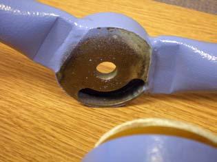
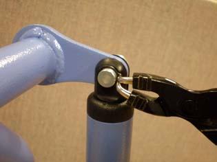
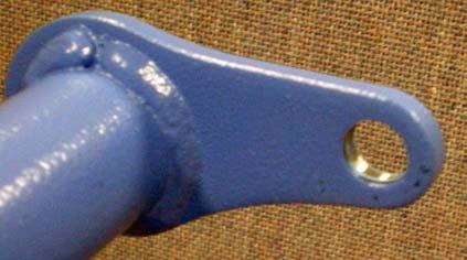
3 INSPECTION CRITERIA Joerns Healthcare recommends a thorough inspection and test of the Oxford/Hoyer APC and its associated Lift, lifting accessories, slings etc. is carried out every six months. The examination and test should be conducted according to the recommendations and procedures below. Joerns Healthcare recommends that authorized service dealers should carry out maintenance, inspection and certified testing only. Note: These recommendations are in compliance with the requirements of Statutory Instrument 1998 No2307 Health and Safety: The Lifting Operations and Lifting Equipment Regulations (LOLER) This is a UK regulation. Outside the UK please check your local requirements. FRAMEWORK Check the cradle for freedom of rotation and swing. Check for wear on the central pivot and wear washer. See Fig. 1, Appendix A. Check the slick pin is correctly fitted and securely locating the fulcrum pin to the boom. See Fig. 2, Appendix A. Check for adequate padding. Check condition of the handgrip. Check that the pivot nut is located onto the threaded stud. See Fig. 3, Appendix A. Check wear on pivot joint washer. See Fig. 4, Appendix A. Check Securi3 location pins are securely fitted to the frame. See Fig. 5, Appendix A. Inspect for excessive wear on the Securi3 location pins. Inspect all welded joints on the cradle frame. Maintenance: - Lubricate main suspension point, centre pivot, and cradle pivot points as necessary. ACTUATOR The actuator should require no maintenance. Check that the circlips are fitted to the actuator pivot pins and correctly located onto the pivot pins. See Fig. 6, Appendix A. Check that the actuator operates in a smooth manner in both directions. Confirm power cut-out at both ends of travel. Check for the free movement of pivot points. Check for wear on the mounting brackets and upper and lower pivot pins. Fig. 7 and 8, Appendix A. Listen for unusual noise which may indicate future break down. CONTROL BOX Check that the control box is securely fitted to the cradle. The control box has a magnetic backing and one securing screw at the back. See Fig. 9, Appendix A. Check that the contacts are clean within the control box area that houses the battery. See Fig. 10, Appendix A. Check that the wire connections into the control box are correct and clipped in place. See Fig. 12, Appendix A. BATTERY Confirm the control box is not sounding audible low battery alarm when operating. Check that the contacts are clean. Fig. 13, Appendix A. Check that the casing is undamaged Check that the battery locates correctly into the control box. Check that the battery locates correctly into the charging unit. 3
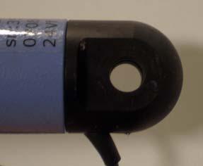
4 INSPECTION CRITERIA HAND SWITCH Check the switch for correct functioning in both directions. Check that the membrane switch is undamaged. See Fig. 14 Appendix A. Check that the membrane switch is fully adhered to the handle. See Fig. 14, Appendix A. If the handle plate has been removed, check that the O ring seal is in good condition and located correctly in the handle plate. See Fig. 15, Appendix A. Note: Silicone seal is required to be applied when replacing the handle plate. Refer to the servicing section. Check that the Serial Number label is located on the handle plate and the details are clearly printed. See Fig. 16, Appendix A. WIRE HARNESSES Check condition of the exposed wire cables. Check condition of the cable connectors. Wires are to be securely located into the connectors and the connector covers fitted over the connectors. See Fig. 17 and 18, Appendix A. Check that the grommets are securely fitted to the cradle frame and sealed with silicon. See Fig. 19 and 20, Appendix A. Check that the cables are connected correctly to the control box. See Fig. 21, Appendix A. CHARGING UNIT Check that the charger, charger lead and charger plug is not damaged. Confirm the charger unit is charging the battery pack. Check mains plug is fitted with the correct rated fuse (when fitted). Check the safety of the input and output lead wiring. Check light indication function. Light Colour Light Mode Indicates Green Blink Charging battery Amber Constant Defective battery or incorrect location of battery Green Constant Battery charged SLINGS AND ACCESSORIES Confirm sling is an Oxford, or Hoyer Sling. Check the load bearing straps and/or clips for wear or fraying. Check the straps and/or clips are securely stitched. Check the body of the sling for wear or cuts in the fabric. Check any side suspenders for wear on the hooks or central suspension point. CLEANING Clean with ordinary soap and water and/or any hard surface disinfectant. Harsh chemical cleaners or abrasives should be avoided as these may damage the surface finish of the lift. Avoid wetting any of the electrical parts. 4
5 TESTING LOAD TEST The load test should be carried out in accordance with the manufacturers test procedures. It is strongly recommended that an authorised service dealer carry out the test. Joerns Healthcare recommends that calibrated weights together with a suitable sling or stillage are utilised to conduct a weight test. Loads applied should be evenly distributed ensuring that the straps/securi3 clips are correctly attached. The APC is to be tested in conjunction with the relevant hoist/lifter it is attached to. Refer to the relevant Service Manual for the hoist/lifter. However, since the APC is an accessory it may be fitted to hoists/lifters that have a different inspection schedule/period. In such cases the APC s inspection period/schedule must be adhered to. The Oxford/Hoyer APC has been designed to the appropriate requirements of: 1. BS EN ISO Hoists for the transfer of disabled persons The hoists are designed to lift the Safe Working Load only. The load lifting capability is set electronically and exceeding the safe working load will affect the actuator s useful life. 2. BS EN ISO Load Raising Test This test is a straightforward moving of a load the equivalent to the Safe Working Load, from the upright/sitting position to reclined/recumbent position of the APC. 3. TEST LOADS - OXFORD/HOYER APC 227kgs/500lbs The load test should be carried out in accordance with the manufacturers test procedures. It is strongly recommended that an authorised service dealer carries out the test. 4. CERTIFICATION An authorised service dealer will issue a test certificate after satisfactory completion of the thorough inspection and test. This certificate will be valid for six months. THOROUGH EXAMINATION REPORT Lifting Operations and Lifting Equipment Regulations 1998 (LOLER UK ONLY) LOLER requires certain information to be included on the report given to a customer after a thorough examination. The information can be found in Schedule 1 (page 56) in the LOLER L113 publication. Joerns Healthcare has prepared a Thorough Examination Report that includes all the required information and a copy can be found on page 14. Please feel free to use this as the basis of your own report. Note: These recommendations are in compliance with the requirements of Statutory Instrument 1998 No2307 Health and Safety: The Lifting Operations and Lifting Equipment Regulations 1998 (LOLER). This is a UK regulation. Outside the UK please check your local requirements. 5
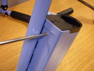
6 SERVICE & MAINTENANCE TOOLS REQUIRED Electrician s screwdriver (to remove slick pin) Circlip pliers (to remove the actuator) Pozi screwdriver. (to remove the control box from mounting bracket and switch plate cover) 17mm A/F socket set (to remove the nyloc nuts) Vernier caliper (to measure pin and hole diameter) Silicon seal (to seal re-wired areas) Medium Strength Thread lock (BLUE) type FRAMEWORK 1 The cradle fulcrum pin is held in place with a slic pin that runs through a steel outer sleeve. Remove the slic pin by depressing the security tab on the one end of the pin (an electricians screwdriver or similar type of flat bladed tool can be used), and withdraw it from the other side. See Fig. 2, Appendix A. 2 Examine the pin for signs of wear and for any deformation of the security tab. The diameter of the pin is 10mm. Reduction in diameter due to wear must not exceed 1mm before replacement. 3 Withdraw the outer sleeve bush from the boom end (hold the cradle while doing this as the cradle may fall) inspect the sleeve for wear as per the pin. See Fig. 2, Appendix A. 4 Remove the black plastic shroud (2 piece) from the spreader bar pivot and examine for damage. Do not lose the pins located inside the shroud. The shroud is an important guard against finger traps. Make sure it will perform this function. Discard and replace if necessary. 5 Take off and retain the O ring that holds the main pivot in the cradle s central boss. Remove the main pivot from the cradle. See Fig. 22 and 23, Appendix A. 6 Examine the main pivot and the central boss for wear. 7 Main pivot: On the hoist, check for wear on the cross-hole for the fulcrum pin. The hole is 16mm in diameter; wear should not exceed 1mm on diameter or 2mm elongation before replacement. See Fig. 2, Appendix A. 8 Check the condition of the white/black acetyl wear washer that sits on the pivot shoulder. The wear washer is there to stop metal-to-metal contact on the pivot shoulder and the central boss on the cradle assembly. If the washer shows any signs of deformation or wear it should be replaced. See Fig. 2, Appendix A. 9 Cradle sling mounting points: Check for wear. The sling mounting points are made from 7.5mm diameter material. Reduction in diameter by wear should not be allowed to exceed 1mm before replacement. See Fig. 5, Appendix A. 10 Remove the domed black plastic caps that cover the cradle pivot joints. See Fig. 3 Appendix A. 11 Check the 17mm A/F Nyloc nuts that hold the cradle to the central suspension assembly are tightened to 6NM. A minimum of one thread should be visible on the stud. See Fig. 3, Appendix A. 12 The cradle when tightened correctly should support a 5kg load or a force of 7N at the handle, and move smoothly on the central suspension assembly. Detachment of the actuator is required to enable this check to be conducted. Refer to the Actuator section. 6
7 SERVICE & MAINTENANCE 13 Lubricate the pivot joints with any light mineral-based grease, or silicon spray. 14 Remove the nyloc nut and washer from the stud. See Fig. 24, Appendix A NOTE: Joerns Healthcare recommends Nyloc nuts should always be replaced if undone. 15 Separate the two frame pieces so that access to the pivot washer and observation on the stud and mechanical stop can be made. See Fig. 25 to 28, Appendix A WARNING: When separating the two frame pieces care is needed not to trap fingers. See Fig. 26, Appendix A 16 Inspect the washer for wear. Check the stud and mechanical stop pin and mating channel. Replace any parts that show damage or significant wear. 17 Refit the washer to the frame and reassemble the two frame pieces. 18 Replace the washer and fit the new nyloc nut. 19 Replace the caps (ensure the cap snaps back into place). After performing all the required actions and checks listed under FRAMEWORK (1 to 19) reassemble the cradle as follows: 20 Lubricate the main pivot, fulcrum pin and sleeve with any light mineral-based grease, or silicon spray, paying particular attention to the pivot shoulder, wear washer, and the fulcrum pin cross-hole. 21 Fit the main pivot to the spreader bar central boss. Refit the retaining O ring. Check rotation of the pivot in the boss. 22 Fit the black plastic shrouds to the cradle pivot and insert into the boom end. Ensure pins are fitted inside the plastic shrouds to assist assembly. Line up the holes in the boom, shrouds and pivot and insert the sleeve. 23 Insert the security pin into the outer sleeve ensuring, that the security tab is visible when it passes through the outer sleeve. An audible click should be heard as the tab springs into position. NOTE: It is most important that the cradle assembly is carefully checked to ensure the wear washer is on the pivot, and the cradle is completely secure to the boom before leaving the hoist. ACTUATOR 1 Examine the actuator mounting point. Without taking the mounting point apart check for signs of wear on the two mounting brackets and pivot pins. Check for excessive movement in the mounting. This will give a good indication of wear but if there is any doubt the assembly should be stripped down as follows: Removal of upper mounting: 2 Remove the circlip that secures the actuator pivot pin to the bracket and extract the pivot pin. See Fig. 29 and 30, Appendix A. 3 Examine the pivot pin for signs of wear and for firm attachment of the remaining circlip. The diameter of the pivot pin is 9.9mm. Reduction in diameter due to wear must not exceed 1mm before replacement. See Fig. 31, Appendix A. 7
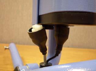
8 SERVICE & MAINTENANCE 4 Examine the actuator mounting bracket on the cradle for wear on the bore of the Bracket. Diameter of the hole is 10mm wear should not exceed 1mm on diameter or 2mm elongation. See Fig. 32, Appendix A. 5 Examine the actuator top for wear. Diameter of the hole is 10mm wear should not exceed 1mm on diameter or 2mm elongation. See Fig. 33, Appendix A. 6 Replace the pivot pin through the actuator and cradle bracket. 7 Fix the fulcrum pin in place using a circlip. (Suitable for groove diameter 9.3mm - Spare kit 0Y0465) Removal of lower mounting: 8 Removal of the lower mounting point is the same process as conducted for the upper mounting. See Fig. 34 to 38, Appendix A. However it may be required to extract some cable from the frame. If this is required refer to section Wiring and Connections. 9 Examine the pivot pin for signs of wear and for firm attachment of the remaining circlip. The diameter of the pivot pin is 9.9mm. Reduction in diameter due to wear must not exceed 1mm before replacement. See Fig. 36, Appendix A. 10 Examine the actuator mounting bracket on the cradle for wear on the bore of the Bracket. Diameter of the hole is 10mm wear should not exceed 1mm on diameter or 2mm elongation. See Fig. 37, Appendix A. 11 Examine the actuator bottom for wear. Diameter of the hole is 10mm wear should not exceed 1mm on diameter or 2mm elongation. See Fig. 38, Appendix A. 12 Removal of the actuator can be achieved after completing activities 2 and 8. Then remove the wire harness from the framework following instructions identified in the Wire and Connections section. NOTE: Joerns Healthcare recommends: NEVER reuse circlips. ALWAYS use circlip pliers for fitting. ENSURE the circlip is properly located in the groove. CONTROL UNIT 1 Check the engagement of the controller with the mounting. The controller has a magnetic back that allows easy location onto the mounting bracket. The use of the screw at the back of the mounting plate ensures that the controller is securely fitted. To remove the control unit unplug the two connectors at the bottom (refer to next note) and remove location screw. See Fig. 39, Appendix A. 2 Check the connector plugs are inserted fully into the sockets on the base of the control unit. The controller is designed so that it does not matter which connector is fitted into the sockets. Removal of the connectors from the sockets is easily achieved by pressing down on the connector retaining clip and then pulling out the connector from the socket, holding onto the connector as this is done. Do not pull on the cable as this may damage the wire connection into the plug. See Fig. 40 and 41, Appendix A. 3 Check the contacts for the battery connection are clean and not damaged. See Fig. 42, Appendix A. 8
9 SERVICE & MAINTENANCE 4 Check the functionality of the audible signals. The signals are indicated with a long, short or multiple beeps. 4.1 Power On (Power is on when the battery is inserted): One extended BEEP 4.2 Sleep Mode: Two short BEEPS 4.3 Low Battery: Two short BEEPS repeated every 24 seconds. (charge battery) 4.4 Start Operation: Two BEEPS (low voltage, charge battery soon) 4.5 During Operation: One long BEEP (the battery charge is too low; only downward motion will be possible). BATTERY 1 The battery service checks required can be conducted when servicing the control unit and the charger unit. Refer to relevant sections within this manual. 2 Check the contacts on the battery connection are clean and not damaged. See Fig. 13, Appendix A. 3 Check that the casing of the battery is undamaged. See Fig. 43, Appendix A. 4 It is recommended that the battery is kept fully charged. Place the battery on charge whenever it is not in use. If it is more convenient to do so, place on charge every night. The charger will not allow the battery to overcharge. Refer to Charger section of this manual for further details to prolong the life of the battery. HAND SWITCH AND HOUSING 1 Check that the membrane switch is firmly located to the handle. The adhesive backed switch prevents ingress of dirt and fluids into the switch housing area. See Fig. 14, Appendix A. 2 Check that the membrane switch is not cracked. 3 Check the switch for correct functioning in both directions. 4 If the membrane switch requires replacing then peel off the switch from the housing. Gently pull out the attached ribbon cable and disconnect from the wire harness. See Fig. 44 to 46, Appendix A. 5 To replace with a new membrane switch. Clean the metal housing to remove any grease or dirt. Connect the connector on the membrane switch to the wire harness. Remove the protective backing off the membrane switch to expose the adhesive backing and carefully locate onto the housing. Ensure that no air bubbles occur when fitting and that the edges provide a seal onto the housing. See Fig. 47 and 48, Appendix A. 6 Remove the sealed plate from the housing by removing the two M3 pozi screws. See Fig. 49, Appendix A. 7 Examine the grommet seal for any sign of damage or distortion. This grommet seal provides ingress protection against dust and fluids. Replace grommet seal if required. See Fig. 50, Appendix A. NOTE: It is required to use silicon seal around the grommet area. 9
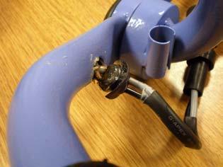
10 SERVICE & MAINTENANCE 8 Examine the connection points of the membrane switch to the wire harness. Connections should be secure. Carefully remove insulation tape if it has been applied. See Fig. 51, Appendix A. 9 Examine internal housing for any fluid ingress or signs of accumulated liquids. Clean out any areas of retained liquid. NOTE: Ensure appropriate personal protection before dealing with any fluid accumulation. 10 Refit grommet seal to plate and secure to housing using the two M3 screws. NOTE: It is required to use silicon seal around the grommet area. WIRING AND CONNECTIONS 1 Examine all exposed wires to ensure that the insulation is intact. See Fig. 52 to 54, Appendix A. 2 Examine all connectors to ensure that the wires are securely fitted to the connectors. See Fig. 17, Appendix A. Removal of the connectors from the sockets is easily achieved by pressing down on the connector retaining clip and then pulling out the connector from the socket, holding onto the connector as this is done. Do not pull on the cable as this may damage the wire connections into the plug. See Fig. 40 and 41, Appendix A. 3 The wiring is housed within the cradle framework to provide additional protection. If this requires to be removed the following procedure can be followed: NOTE: The use of draw wires are recommended when requiring to replace any wiring. Actuator cabling: 4.1 Carefully pull out the grommet from the cradle framework. See Fig. 55, Appendix A. 4.2 Carefully pull out the cable from the cradle framework. There will be some resistance as the two connectors at the end of the cable require to be fed through the hole in the cradle framework. See Fig. 56, Appendix A. 4.3 Disconnect the two connectors from the attaching wire harness, which is connected to the controller. See Fig. 57, Appendix A. 4.4 Replacing the actuator cabling is the reverse process to removal. The actuator comes complete with wires, connectors and grommet. Connect the connectors on the actuator wire to the wire harness connected to the control box. Feed through the wires with the connectors into the cradle framework and then fit in the grommet. 4.5 Apply silicon seal to the grommet at the cable entry point to provide a seal. See Fig. 58, Appendix A. Control Unit/Switch cabling: NOTE: The Cable harness that plugs into the Control Unit is one assembly that connects to both the actuator and the membrane switch in the handle. Connection points are identified in the Wire and Connections section for the actuator and in the Hand Switch and Housing section for the membrane switch. 5.1 Disconnect the two connectors from the Control Unit. Details identified in Control Unit section. 5.2 Disconnect the actuator from the cable harness. Refer to details in the Actuator cabling section. 10
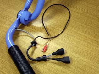
11 SERVICE & MAINTENANCE 5.3 Remove the housing plate on the handle and disconnect the membrane switch. The membrane switch does not require removing when requiring the wire harness to be disconnected. After removing the housing plate, the wires are exposed to allow the connectors to be disconnected. See Fig. 59 to 61, Appendix A. NOTE: Care must be taken with handling the ribbon cable to prevent damage. 5.4 Detach the grommet from the metal clip and carefully pull out the grommet from the cradle framework. See Fig. 62 and 63, Appendix A. 5.5 Carefully pull out the cable harness. The actuator cable is identified with the two red connectors. The Membrane Switch cable is identified by the 4 Pin connector. See Fig. 64, Appendix A. 5.6 To replace the cable harness re-insert the cabling into the frame and feed through the connectors to the appropriate holes to allow connection to the actuator and membrane switch. 5.7 Reconnect the actuator as previously instructed earlier in this section. 5.8 Reconnect the membrane switch and refit the housing plate. Ensure that wires are free from entrapment and that silicon seal has been applied around the grommet seal prior to securing the plate to the housing. Details are further explained in the Hand Switch and Housing section. 11
12 FAULT FINDING The following are guidelines in determining the root cause of a problem. Should the fault not be identified then please contact Customer Services/Technical Support for further assistance. PROBLEM: Actuator does not function in either direction. Possible Fault Actuator is damaged Battery not engaged into controller correctly Battery is not charged sufficiently Controller is damaged Connector to the controller is disconnected Wire harness is damaged Handle switch is disconnected Handle switch is damaged Pivot Points are seized Remedy 1. Check that the battery is engaged into the controller correctly. 2. If actuator does not work then check that battery is charged sufficiently or replace with fully charged battery. 3. If not working disconnect from the controller and connect to new controller and re-check. If actuator works replace the original controller. 4. If actuator does not work then remove the actuator from it s mounting points and check if it works. If actuator works check all pivot points and lubricate/ replace parts as required. 5. If actuator does not work then disconnect the actuator from the wire harness in the frame and connect to a new actuator. If actuator works replace the original actuator. 6. If actuator does not work then disconnect the handle switch from the wire harness and reconnect a new switch. If actuator works replace the handle switch. 7. If actuator does not work then connect the original actuator and controller to a new wire harness and test. If the actuator works replace the original wire harness. PROBLEM: Actuator making unusual noise. Possible Fault Actuator is damaged Pivot Points are seized Remedy 1. Remove the actuator from the mounting points and check for free movement of the pivot points and the main pivot point for the cradle. Refit the actuator. 2. If the actuator continuous to make a similar noise remove the actuator from it s mounting points. Disconnect the actuator from the wire harness in the frame and connect to a new actuator. Refit to the mounting points and test. 12
13 FAULT FINDING PROBLEM: Cradle does not rotate. DO NOT continue using the cradle until problem is corrected. Possible Fault Washer worn Pin damaged Frame damaged Remedy 1. Remove the cradle from the hoist. Remove the O ring from the pivot pin and remove the pin from the frame. Check the pin for damage and the washer for wear. Check the area of the frame where the pivot pin locates. Replace any damaged or worn parts identified. Refit the pivot pin to the cradle, refit the O ring and locate onto the hoist. 2. If the cradle still fails to rotate then remove the cradle from the frame and contact Customer Services - DO NOT use the cradle. PROBLEM: Controller making unusual noise. First check that the noise is not part of the functionality of the charger - refer to the Control Unit section of the Service Manual for details. Possible Fault Controller is damaged Remedy 1. Remove the battery and disconnect the two connectors from the base of the controller. 2. Remove the securing screw and lift out the controller. The controller is fitted internally with a magnetic backing to assist location to the frame. Replace with a new controller. PROBLEM: General unusual noise. First check that the noise is not part of the functionality of the charger - refer to the Control Unit section of the Service Manual for details. Possible Fault Actuator is damaged Actuator is damaged Pivot Points are seized Remedy Determine where the noise is originating from. Pivot Pin attached to cradle and hoist - refer to fault finding for Cradle does not rotate. Actuator - refer to fault finding for Actuator making unusual noise. Controller - refer to fault finding for Controller making unusual noise. Other Pivot areas - refer to fault finding for Actuator making unusual noise. 13
14 FAULT FINDING PROBLEM: Can t attach the sling to the Cradle. First check that the correct type is being used for the Cradle. The slings must have Securi3 clips fitted. Possible Fault Location Pins are damaged Securi3 clips are damaged Remedy 1. Check location pins for damage or wear. If identified as damaged or worn then a replacement frame is required. 2. Check the securi3 clips on the sling for damage or wear. If identified as damaged or worn then a replacement sling is required. PROBLEM: Black debris identified around the pivot pin locating the cradle to the hoist. DO NOT continue using the cradle until problem is corrected. Possible Fault Washer worn Pin damaged Frame damaged Remedy 1. Remove the cradle from the hoist. Remove the O ring from the pivot pin and remove the pin from the frame. Check the pin for damage and the washer for wear. Check the area of the frame where the pivot pin locates. Replace any damaged or worn parts identified. Refit the pivot pin to the cradle, refit the O ring and locate onto the hoist. PROBLEM: Black debris identified around the actuator and/or actuator mounting points. Possible Fault Actuator is damaged Mounting Points are seized Remedy 1. Refer to Actuator heading in the Service and Maintenance section. 2. Remove the actuator from its mounting points and check for wear on the end location holes. Replace actuator if identified as damaged/worn. 3. Check actuator for smooth running. If identified as faulty then replace the actuator. Check the pivot pins and replace if identified as damaged or worn. 14
15 EXPLODED VIEW 15
16 PARTS LIST No. Part No. Description 1. 0Y0457 Actuator 2. 0Y0459 Battery Charger (UK) 3. 0Y0460 Battery Charger (EU) 4. 0Y0458 Battery Charger (US) 5. 0Y0461 Control Box 6. 0Y0462 Battery 7. 0Y0463 Hand Switch Assembly 8. 0Y0464 Wire Harness between control box, actuator and switch 9. 0Y0465 Hardware (Fixings) 10. 0Y0380 Washer and O-ring kit 16
17 LOLER: Thorough Examination Report Lifting Operations and Lifting Equipment Regulations 1998 Schedule 1 Client Name & Address Tel Address of Examination Model Serial No. Date of Manu. Date of last Examination Safe Working Load Commissioning Examination Yes No Safe to Operate Yes No N/A Periodic Examination Yes No Interval of Examination 6 Months 12 Months Examination Scheme Exceptional Safe to Operate Yes No N/A Defective Parts (Immediate Attention): Part Number Description Defect Action Taken Defects requiring rectification at a later date: Part Number Description Defect Action Taken Latest Date Next examination due date Load test conducted according to BS 5827 BS EN ISO Other (state) Thorough examination carried out (Date) Name of Examiner Job Title On behalf of (Company/Organisation) Address Signed Date of Report Signed on behalf Name & address 17


18 APPENDIX A Hole diameter 10mm O ring Washer FIG. 1A Fulcrum Pin FIG. 1B FIG. 1C FIG. 2A Slic Pin FIG. 2B FIG. 3 Frame Pivot Area FIG. 4 FIG. 5A Securi3 Location Pins FIG. 5B FIG. 6A FIG. 6B FIG. 7A Mounting Brackets FIG. 7B 18


19 APPENDIX A Contacts FIG. 8A Upper Pin FIG. 8B Lower Pin FIG. 9 FIG. 10 -ve Terminals +ve Terminal -ve Terminals +ve Terminal FIG. 11 FIG. 12 FIG. 13 FIG. 14 FIG. 15 FIG. 16 FIG. 17 FIG. 18 FIG


20 APPENDIX A FIG. 20 FIG. 21 FIG. 22 FIG. 23 FIG. 24 FIG. 25 FIG. 26 Stud Pivot Washer Mechanical Stop Pin FIG. 27 FIG. 28 FIG. 29 FIG. 30 FIG. 31 FIG


21 APPENDIX A FIG. 33 FIG. 34 FIG. 35 FIG. 36 FIG. 37 FIG. 38 Mechanical Stop Pin FIG. 39 FIG. 40 FIG. 41 -ve Terminals +ve Terminal FIG. 42 FIG


22 APPENDIX A FIG. 44 FIG. 45 FIG. 46A FIG. 46B Remove backing to expose adhesive Membrane switch with adhesive exposed FIG. 47 FIG. 48 FIG. 49 FIG. 50 FIG. 51 FIG. 52 FIG. 53 FIG


23 APPENDIX A FIG. 55 FIG. 56 FIG. 57 Apply Silicon Seal FIG. 58 FIG. 59 FIG. 60 FIG. 61 FIG. 62 FIG. 63 FIG
24 NOTES 24
25 Joerns Healthcare Limited High Street Wollaston Stourbridge West Midlands DY8 4PS England Tel +44(0) Fax +44(0)
Oxford /Hoyer. Professional Series. Presence Lift SERVICE MANUAL Rev B
 Oxford /Hoyer Presence Lift Professional Series SERVICE MANUAL CONTENTS Pages 3-4 Inspection Criteria of the Oxford/Hoyer Presence Page 5 Testing of the Oxford/Hoyer Presence Pages 6-13 Service and Maintenance
Oxford. Manufacturer s Contact Details. Contents. Oxford Presence. English
 English Manufacturer s Contact Details EUROPE Joerns Healthcare Limited Drakes Broughton Business Park, Worcester Road Drakes Broughton, Pershore, Worcestershire WR10 2AG United Kingdom Tel: 0844 811 1156
User Instruction Manual Classic Lifts Mini Midi Major Maxi. To avoid injury, read user manual prior to use.
 User Instruction Manual Mini Midi Major Maxi To avoid injury, read user manual prior to use. Oxford English Contents 1. Oxford Classic Lift Range... 3 2. Introduction: About Your Lift... 5 3. Assembly
U S E R M A N U A L. To avoid injury, read user manual prior to use. enablelifecare.com.au. Joerns Hoyer Presence
 U S E R M A N U A L Hoyer Presence To avoid injury, read user manual prior to use. enablelifecare.com.au Contents 1. The Hoyer Presence Patient Lift... 3 2. Introduction: About Your Lift... 4 3. Assembly
User Instruction Manual Hoyer. HPL700 and HPL700WSC To avoid injury, read user manual prior to use.
 User Instruction Manual Hoyer HPL700 and HPL700WSC To avoid injury, read user manual prior to use. Hoyer English Contents 1. Introduction... 3 2. Safety Precautions... 4 3. Assembly and Commissioning Instructions...
Contents. Oxford Calibre. English
 Oxford English Contents 1. The Oxford Patient Lift... 3 2. Introduction: About Your Lift... 4 3. Assembly and Commissioning Instructions... 5 4. Safety Precautions... 10 5. Smart Monitor & Handset... 12
INSTRUCTION MANUAL. Pacific Self-locking Beam Trolleys Pacific Adjustable Angle Clamps Pacific Top Girder Clamps
 INSTRUCTION MANUAL Pacific Self-locking Beam Trolleys Pacific Adjustable Angle Clamps Pacific Top Girder Clamps IMPORTANT Please read this instruction manual before using these products. This manual contains
English. Fitting Instructions: Trophy and Trophy SE A and A of 10 A Parts Supplied:
 English Fitting Instructions: Trophy and Trophy SE A95086and A950856 Thank you for choosing this Triumph genuine accessory kit. This accessory kit is the product of Triumph's use of proven engineering,
Accessory Fitting Instructions
 Accessory Fitting Instructions Kit Number Models Affected A9689 Thruxton 00 A96808 Thruxton 00 R Low Handlebar Kit Front Fairing Kit Kit Number Models Affected A97080 Thruxton 00 A97084 Thruxton 00 R Note:
atient lifters Assembly, Maintenance & Specifications Manual SUNRISE HML400 Hoyer Manual Patient Lift HPL400 Hoyer Power Patient Lift Sunrise Medical
 SUNRISE 800-556-5438 Oshkosh, WI 54901 2815 Oregon Street Continuing Care Group Sunrise Medical HML400 Hoyer Manual Patient Lift HPL400 Hoyer Power Patient Lift Assembly, Maintenance & Specifications Manual
ZE ZE ZE. Simplex expanding wedge brake Assembly and Maintenance Instructions
 Simplex expanding wedge brake Assembly and Maintenance Instructions Simplex expanding wedge brake Assembly and Maintenance Instructions Edition 1 This publication is not subject to any update service.
Mechanical Sliding Caliper Disc Brake. Type PAN 19-1 Assembly and Maintenance Instructions
 WABCO Mannheim Mechanical Sliding Caliper Disc Brake Type PAN 19-1 Assembly and Maintenance Instructions WABCO Radbremsen GmbH Postfach 71 02 63 D-68222 Mannheim Bärlochweg 25 D-68229 Mannheim +49 (0)6
PIL0478 ISSUE 01/ 07/16
 ISSUE 01/ 07/16 PIL0478 ZAFIR G9 CEILING FITTING PIL0478 ISSUE 01/ 07/16 PART C PART E PART 21 SELV 1 1.B 1 3.1 3.3 3.4 3.5 3.6, 3.8 3.10 3.12 3.14 3.16 3.17 3.18 3.19 3.19 ATTENTION! THE TABLE BELOW
Shelbourne header monitor kit Up to 2004
 Shelbourne header monitor kit Up to 2004 The Shelboume Header Monitor monitors and displays the running speeds of the Stripping Rotor and the Auger of the combine header. The speed of either can be displayed
Installation, Usage & Maintenance Guide
 3-Point Seat Belt Installation, Usage & Maintenance Guide For Fixed, Suspension & Bench Seats This guide should remain with the vehicle and passed on to subsequent vehicle owners to be kept for future
APT14 Automatic Pump Trap Installation and Maintenance Instructions
 6120250/7 IM-P612-04 ST Issue 7 APT14 Automatic Pump Trap Installation and Maintenance Instructions 1 Product information 2 Operation 3 Installation Closed loop steam systems only 4 Commissioning 5 Maintenance
Graduate 150 Scholar 175 Master 200
 Instruction Manual for Graduate 150 Scholar 175 Master 200 Contents Unihoist Ltd Electric and Hydraulic illustrations..... 2-3 Introduction.. 4 Assembly and commissioning instructions... 5-6 Safety precautions....
Maintenance and Repair Instructions TM 89/03
 TM 89/0 410 X 180 Simplex 410 X 180 Duplex 500 X 10 Simplex 500 X 160 Simplex 500 X 180 Duplex The brake described in this manual is subject to development and corresponds to the state-of-the-art at the
Fitting Instructions: Street Triple from VIN and Street Triple R from VIN A
 English Fitting Instructions: Street Triple from VIN 560477 and Street Triple R from VIN 560477 A9808113 Thank you for choosing this Triumph genuine accessory kit. This accessory kit is the product of
2003 Dodge Dakota ENGINE PERFORMANCE Removal & Installation - Dakota
 FUEL LINE DISCONNECT FITTINGS NOTE: Fuel lines may contain single tab, dual tab or plastic retainer ring disconnect fitting. Determine type of disconnect fitting used and use proper procedure for proper
Primus Wind Power. AIR Circuit Replacement Instructions
 Primus Wind Power AIR Circuit Replacement Instructions Items included with this kit: (see Exploded View p. 3) ITEM ITEM NAME QUANTITY 1 SCREW - SOCKET HEAD - 10-24 X 1-1/2" 4 includes 1 spare 2 O-RING
The University Bath Hoist & University Transporter
 The University Bath Hoist & University Transporter University Electric Bath Hoist English The University Bath Hoist & University Transporter Contents Introduction 3 Side and End fitting illustration 4
Service Manual. Model L500 and L600 Smart Lift. WARNING: Cancer and Reproductive Harm - Form #1-144 Rev.
 Service Manual Model L500 and L600 Smart Lift WARNING: Cancer and Reproductive Harm - www.p65warnings.ca.gov. Form #1-144 Rev. 2/5/19 Table of Contents Parts Breakdown 3 Monthly Maintenance Checklist 5
IMPORTANT INSTRUCTIONS FOR OPERATION & MAINTENANCE OF
 IMPORTANT INSTRUCTIONS FOR OPERATION & MAINTENANCE OF CONVEYORS EASIKIT 300 EASIKIT 450 EASIKIT 600, 900, 1200 & 1500 The manufacturer does not accept responsibility for any loss, damage to other equipment,
DB4604 GMR-SD and GMR40-SD Disc Brake Caliper - Spring Applied, Air Released
 DB464 GMR-SD and GMR4-SD Disc Brake Caliper - Spring Applied, Air Released Nominal dimensions given. For specific dimensions please contact Twiflex Limited. For GMR Mk 2 caliper details see DB 364 Air
Safelift Overhead Runway Beams & Rolling Beam Cranes
 Operation & Maintenance Instructions Instructions for Safe Use Safelift Overhead Runway Beams & Rolling Beam Cranes Certification Safelift overhead runway beams and rolling beam cranes are lifting appliances
Brake Upgrade Kit Fitting Instructions Bonneville America
 WARNING: Always have Triumph approved parts, accessories and conversions fitted by a trained technician of an authorised Triumph Dealer. The fitment of parts, accessories and conversions by a technician
TOYOTA TUNDRA BIG BRAKE KIT Section I - Installation Preparation
 TOYOTA TUNDRA 2007- BIG BRAKE KIT Section I - Installation Preparation Part Number: PTR09-34070 Kit Contents Item # Quantity Reqd. Description 1 1 Brake Rotor, LH Front 2 1 Brake Rotor, RH Front 3 1 Brake
Falcon 5250 complete repair kit
 Towing and Suspension Solutions 855010-02 08-14 Falcon 5250 complete repair kit part number 910003-55 This kit contains the components to replace the Falcon 5250 Autowlok button assemblies, collar shoulder
GMR-S and GMR40-S Disc Brake Caliper - Spring Applied, Air Released
 (GMR) 9 (GMR) ø GMR-S and GMR-S Disc Brake Caliper - Spring Applied, Air Released DB Nominal dimensions given. For specific dimensions please contact Twiflex Limited. For GMR Mk caliper details see DB
Operating & Maintenance Manual
 Operating & Maintenance Manual CONTENTS CONTENTS INTRODUCTION Introduction 2 Operating Specifications 3 Working Envelope Diagram 3 Do s and Don ts 4 Primary Components 5 Operating Procedures (incl. Emergency
SERVICE PROCEDURES FOR CLUTCH HYDRAULIC UNITS
 SERVICE PROCEDURES FOR CLUTCH HYDRAULIC UNITS SAFETY PROCEDURES Always follow the vehicle manufacturer's recommended safety procedures in your Shop and Owners Manual. REQUIRED TOOLS Flat blade screwdriver,
Accessory Fitting Instructions
 Accessory Fitting Instructions A97588 A97599 A975899 A97589 To be used with A97588 A97599 A975800 A975890 A975890 A975900 A97580 A9758 A97588 A97599 Grab Rail Mounting Kit, Chrome Bonneville T00 and Bonneville
 AUTOGARD SERIES 820 TORQUE LIMITER Installation and Maintenance Manual DB0009 Issue 11 21 Feb 2017 British Autogard Ltd 2 Wilkinson Rd., Love Lane Industrial Estate, Cirencester, Glos., GL7 1YT UK Tel.
354 CHAPTER EIGHT WATER PUMP
 354 CHAPTER EIGHT 33 Shift handle F : Forward N : Neutral R : Reverse proper alignment of the water tube to the water pump opening during each installation attempt. Make sure the locating pins enter the
Accessory Fitting Instructions
 Accessory Fitting Instructions Side Mounted Licence Plate Kit - USA Only Kit Number A975070 Models Affected Bonneville Bobber, Bonneville Bobber - Black, Bonneville Speedmaster from VIN 794 Thank you for
BEAM CLAMP INSTRUCTION MANUAL
 BEAM CLAMP INSTRUCTION MANUAL Imported exclusively for the Global Lifting Group by Pacific Hoists Pty. Ltd. & Pacific Hoists Ltd. 2 SAFETY INSTRUCTIONS THE FOLLOWING SAFETY INSTRUCTIONS OUTLINE THE CARE
MAJOR INSPECTION SPECIFIC RECOMMENDATIONS
 MAJOR INSPECTION SPECIFIC RECOMMENDATIONS 25.8.10 MODELS: TT16, TT19 1 GENERAL This document outlines specific recommendations relating to GMJ EWP Models TT16-300, TT19-250 and TT19-350S. It is to be read
STAND MODEL FOR MACH M2
 Mounting instructions Directions for use STAND MODEL FOR MACH M2 Stand lamps: Mach M2... Mach M2 F... Order No. 170 120 1300 Order No. 170 230 1300 GmbH u. Co. KG, Flossmannstrasse 28, D-85560 Ebersberg
INSTALLATION INSTRUCTIONS Mopar Performance 2 Lift System 2009 and Newer Dodge Ram 1500 (DS) 4WD PART NUMBER P
 4WD PART NUMBER P") INTRODUCTION Installation requires a professional mechanic. Prior to beginning, inspect the vehicle s steering, driveline, and brake systems, paying close attention to the suspension link arms and bushings,
INTRODUCTION Installation requires a professional mechanic. Prior to beginning, inspect the vehicle s steering, driveline, and brake systems, paying close attention to the suspension link arms and bushings,
HitchHoist Assembly & Operating Instructions IMPORTANT NOTICE
 HitchHoist Assembly & Operating Instructions IMPORTANT NOTICE FAILURE TO READ AND COMPLY WITH THE INSTRUCTIONS PRINTED IN THIS MANUAL COULD RESULT IN SERIOUS INJURY! IT IS STRONGLY RECOMMENDED THAT PERSONNEL
Oxford /Hoyer. Journey User Instruction Manual & Warranty. Journey Manuel de l utilisateur et garantie
 User Instruction Manual & Warranty To avoid injury, read user manual prior to use. Manuel de l utilisateur et garantie Afin d éviter tout accident, veuillez lire attentivement la notice avant utilisation.
1989 Jeep Cherokee. STEERING COLUMN' '1989 STEERING Jeep Steering Columns STEERING COLUMN STEERING Jeep Steering Columns
 STEERING COLUMN 1989 STEERING Jeep Steering Columns DESCRIPTION All models use collapsible steering columns. All columns have integral ignition switch and locking device. Optional tilt wheel is available
Service Manual Model L1000 Smart Lift
 Service Manual Model L1000 Smart Lift Form #1-147 Rev. 10/1/13 Table of Contents Parts Breakdown 3 Monthly Maintenance Checklist 5 Smart Lift Operating Instructions 7 Scale Calibration 8 Advanced Smart
U S E R M A N U A L. To avoid injury, read user manual prior to use. enablelifecare.com.au. Hoyer Journey. Joerns Hoyer Presence
 U S E R M A N U A L Hoyer Journey To avoid injury, read user manual prior to use. enablelifecare.com.au Contents 1. The Hoyer Journey Patient Lift... 3 2. Introduction: About Your Lift... 4 3. Assembly
Standard Valves Series Globe Valves Series Angle Valves Series Way-Valves
 Installation, Operation, Maintenance Instructions Standard Valves Series 035 000 Globe Valves Series 031 000 Angle Valves Series 033 000 3-Way-Valves 1 GENERAL INFORMATION These instructions are designed
Gearbox Installation Manual
 Gearbox Installation Manual Rotork Gears IW, MOW, MTW, IB and IS ranges (Electronic copy available on www.rotork.com)! This manual contains important safety information. Please ensure it is thoroughly
3-TONNE GARAGE JACK OPERATION & MAINTENANCE INSTRUCTIONS MODEL NO: CTJ3000GB PART NO: ORIGINAL INSTRUCTIONS
 3-TONNE GARAGE JACK MODEL NO: CTJ3000GB PART NO: 7623032 OPERATION & MAINTENANCE INSTRUCTIONS ORIGINAL INSTRUCTIONS GC1216 2 INTRODUCTION Thank you for purchasing this CLARKE Garage Jack. Before attempting
Giant Hydraulic Disc Brake System
 Giant Hydraulic Disc Brake System INSTALLATION INSTRUCTI IMPORTANT NOTICE Contact the place of purchase or Authorized Giant Retailer for information on detail of installation and maintenance. Read this
SERVICE MANUAL. Koala
 SERVICE MANUAL Koala US How to contact Permobil Permobil Inc. USA 6961 Eastgate Blvd. Lebanon, TN 37090 USA Phone: 800-736-0925 Fax: 800-231-3256 Email: info@permobilusa.com Head Office of the Permobil
2003 Dodge Pickup R DRIVE AXLES' 'Axle Shafts - Front - Ram Pickup WD DRIVE AXLES
 2002-04 DRIVE AXLES Axle Shafts - Front - Ram Pickup 1500 4WD DESCRIPTION Vehicles equipped with 4WD and C205F front axle assembly use equal length axle shaft system to deliver power from front differential
24V 3A EN54 Ancillary Power Supply
 24V 3A EN54 Ancillary Power Supply Normal supply - green light on Fault condition - call Engineer Control relay - activated 3A Power Supply C-TEC Manufactured in England by C-Tec EN 54-4 : 1997 INSTALLATION
English. Fitting Instructions: Sprint GT 1050 A and A of 12
 English Fitting Instructions: Sprint GT 050 A950855 and A950856 Thank you for choosing this Triumph genuine accessory kit. This accessory kit is the product of Triumph's use of proven engineering, exhaustive
Heavy Duty Miniature Quick-Change Applicator (End-Feed Type) with Mechanical or Air-Feed Systems
 with Mechanical or Air-Feed Systems") Heavy Duty Miniature Quick-Change Applicator (End-Feed Type) with Mechanical or Air-Feed Systems Instruction Sheet 408-8039 02 JUN 16 Rev G Ram Post Wire Disc Insulation Disc Insulation Crimper Stripper
Heavy Duty Miniature Quick-Change Applicator (End-Feed Type) with Mechanical or Air-Feed Systems Instruction Sheet 408-8039 02 JUN 16 Rev G Ram Post Wire Disc Insulation Disc Insulation Crimper Stripper
XChange Seat Service and Maintenance Guide
 XChange Seat Service and Maintenance Guide Table Of Contents Page General Information... 1 Registration Information... 1 Seat Cushion Latch... 2 Lap Shoulder Belt Replacement... 2 Sliding Buckles Replacement...
Assembly instructions Original parking distance control system, Volkswagen
 Assembly instructions Original parking distance control system, Volkswagen Set contents: 1 x controller 1 x buzzer 4 x sensor Set contents: 4 x covering rings 4 x protective rings Special tools, test and
Melody 1 Platform Lift
 USER MANUAL Melody 1 Platform Lift Original instructions CONTENTS PAGE Introduction 4 Description 4 General Do s and Don ts 6 Controls 7 Operating the Lift 8 Emergency Procedures 9 Platform Gate Lock
Southwest Windpower Instruction Sheet AIR-X Circuit Replacement Kit
 Southwest Windpower Instruction Sheet AIR-X Circuit Replacement Kit Tools Required 5 / 32 Hex key 5 / 16 Hex key 7 / 64 Hex key Standard screwdriver Pair of external snap ring pliers Rubber mallet Hammer
A-320 Balanced 1st Stage
 Technical Manual A-320 Balanced 1st Stage A Manual for Repair and Maintenance Technicians View: Select Full Screen mode to use page arrows. FEATURES Extra durable satin chrome plated brass body. Fully
ACROBAT SWING STAND MODEL
 Mounting instructions Directions for use ACROBAT SWING STAND MODEL Stand lamps: Mach 120... Mach 120F... Mach 130... Mach 130F... Mach LED 120... Mach LED 120F... Mach LED 130... Mach LED 130F... Order
Impeller Replacement
 Impeller Replacement Threaded Shaft Frame Mount H 806 Clockwise Rotation Volute shown. 1149 0794 1 Unfasten hardware holding volute to bracket. Remove volute to expose impeller. Peel off old volute gasket
Parking brake Mechanical brake acting on rear wheels
 11 Brake System 11.1 General SPECIFICATIONS EJTC0010 Master cylinder Type Tandem type I.D. mm(in.) 20.64 mm (0.813 in.) Fluid level warning sensor Provided Brake booster Type Vacuum Boosting ratio 4.0
Sub Section Title Page No.
 Sub Section Title Page No. 1 Introduction 3 2 Routine Maintenance 3 3 Disassembly 4 3.1 Disassembly of Double Crank Design 4 3.2 Disassembly of Scotch Yoke Design 5 3.3 Disassembly of Actuator Cylinder
Electric Hi Lo Screen lift Trolley Mount 8960
 Electric Hi Lo Screen lift 750 - Trolley Mount 8960 - Max Capacity 100kg - Min Capacity 5kg - Screens upto 86 WARNING! THIS IS NOT A TOY! WARNING! CHILDREN SHOULD NOT OPERATE LIFT OR HAVE ACCESS TO THE
Falcon 2 & BlackHawk complete repair kit
 Falcon 2 & BlackHawk complete repair kit part number 910003-60 Towing and Suspension Solutions This kit contains the components to replace the Falcon 2 or BlackHawk Autowlok button assemblies, collar shoulder
BRAKE SYSTEM Return To Main Table of Contents
 BRAKE SYSTEM Return To Main Table of Contents GENERAL... 2 BRAKE PEDAL... 10 MASTER CYLINDER... 13 BRAKE BOOSTER... 16 BRAKE LINE... 18 PROPORTIONING VALVE... 19 FRONT DISC BRAKE... 20 REAR DRUM BRAKE...
Yesterday s challenge Today s solution. User Manual. innova.uk.com
 Yesterday s challenge Today s solution User Manual innova.uk.com Contents 2 www.innova.uk.com Contents Contents 1. Purpose & Use 1.1 Introduction 4 1.2 Who are Innova? 5 1.3 Unpacking & preparation 6 1.4
HR25 Solo. Installation and User Instructions. Through the Wall Heat Recovery Ventilators
 abc GB HR25 Solo Installation and User Instructions Models:- HR25 Solo HR25 Solo L HR25 Solo H HR25 Solo LH Through the Wall Heat Recovery Ventilators PLEASE READ INSTRUCTIONS IN CONJUNCTION WITH ILLUSTRATIONS.
This file is available for free download at
 This file is available for free download at http://www.iluvmyrx7.com This file is fully text-searchable select Edit and Find and type in what you re looking for. This file is intended more for online viewing
Maintenance Information
 80234313 Edition 2 May 2014 Air Grinder, Die Grinder, Sander and Belt Sander Series G1 (Angle) Maintenance Information Save These Instructions Product Safety Information WARNING Failure to observe the
Accessory Fitting Instructions
 Accessory Fitting Instructions Top Box Kit Kit number T5097 T5060 T504 T5680 A9500748 A9500749 To be used with Models Affected Tiger Explorer, Tiger Explorer XC, Tiger Explorer XR, Tiger Explorer XRX,
BRAKE SYSTEM Nissan 240SX DESCRIPTION BRAKE BLEEDING * PLEASE READ FIRST * BLEEDING PROCEDURES ADJUSTMENTS BRAKE PEDAL HEIGHT SPECS TABLE
 BRAKE SYSTEM 1990 Nissan 240SX 1990 BRAKE SYSTEMS Nissan Disc & Drum Axxess, Maxima, Pathfinder, Pickup, Pulsar NX, Sentra, Stanza, 240SX, 300ZX DESCRIPTION All brake systems are hydraulically operated
P-600. Technical Manual. Troubleshooting Repairs Replacements
 P-600 Technical Manual Troubleshooting Repairs Replacements Table of Contents P-600 Lift Symptoms and Problems Finding the Problem Before Getting Inside 3 Pneumatic Systems 4 Electrical Systems 5 Mechanical
Installation Instructions
 Preparing your vehicle to install your brake system upgrade 1. Rack the vehicle. 2. If you don t have a rack, then you must take extra safety precautions. 3. Choose a firmly packed and level ground to
ELECTRICAL CONNECTORS B.1
 ELECTRICAL CONNECTORS B. GENERAL The following table provides a brief description of the connectors found on your motorcycle. Connector numbers are listed in [brackets] in this manual. Table B-. Electrical
Euro Lightweight Wheeled Walker
 Euro Lightweight Wheeled Walker Handle with lever brake Backrest Brake cable Handle height adjustment button Removable shopping bag 8 inch (200 mm) wheels Cane holder user guide Prior to use please read
3 Turbo Downpipe Installation Audi A3 / Volkswagen GTI / Volkswagen Jetta 2.0L FSI/TSI Turbo CD100013
 Please take time to read and understand these installation instructions. APR recommends that installation of this system be performed by a qualified service center or professional muffler installer who
disc brake axle with WABCO calipers
 1 2 disc brake axle with WABCO calipers 3 4 disc brake axle with WABCO calipers 5 6 disc brake axle with WABCO calipers IMT axles are supplied as non-cambered and are within the limits of a 2 minute negative
English. Fitting Instructions: Bonneville and Bonneville T100 A , A and A of 9. Parts Supplied:
 English Fitting Instructions: Bonneville and Bonneville T00 A958085, A958086 and A958087 Thank you for choosing this Triumph genuine accessory kit. This accessory kit is the product of Triumph's use of
Performance Brake Caliper Guide Bushing Set Installation Guide
 Performance Brake Caliper Guide Bushing Set Installation Guide Proper service and repair procedures are vital to the safe, reliable operation of all motor vehicles as well as the personal safety of those
REMOVAL & INSTALLATION
 REMOVAL & INSTALLATION REAR DISC BRAKE PADS Removal Raise and support vehicle. Remove wheels. Thoroughly clean outside of caliper to prevent dust and dirt from entering inside. Support caliper with a piece
Before equipment use, please read this operation manual carefully. Serial Number: Date Purchased:
 Pushed & Geared Trolleys OPERATION MANUAL This operation manual is intended as an instruction manual for trained personnel who are in charge of installation, maintenance, repair etc. Before equipment use,
Tooling Assistance Center
 Safeguards are designed into this application equipment to protect operators and maintenance personnel from most hazards during equipment operation. However, certain safety precautions must be taken by
Heavy Duty Miniature Quick-Change Applicator (Side-Feed Type) with Mechanical or Air Feed Systems
 with Mechanical or Air Feed Systems") Heavy Duty Miniature Quick-Change Applicator (Side-Feed Type) with Mechanical or Air Feed Systems Instruction Sheet 408-8040 30 NOV 17 Rev H Ram Assembly Ram Post Locking Screw Stock Drag Drag Release
Heavy Duty Miniature Quick-Change Applicator (Side-Feed Type) with Mechanical or Air Feed Systems Instruction Sheet 408-8040 30 NOV 17 Rev H Ram Assembly Ram Post Locking Screw Stock Drag Drag Release
Superlift Leveling System / 6 Upgrade System for 2004 and Newer Ford F-150 4WD INSTALLATION INSTRUCTIONS
 FORM #9905.02-032907 PRINTED IN U.S.A. PAGE 1 OF 7 INTRODUCTION Superlift 0.5-2 Leveling System / 6 Upgrade System for 2004 and Newer Ford F-150 4WD INSTALLATION INSTRUCTIONS Installation requires a professional
GL1200T Cut & Seal. (GL1200 Seal only)
") GL INSTRUMENTS & Operating Instructions Safe Seal Cut & Seal Welder for Filter Sacks GL1200T Cut & Seal (GL1200 Seal only) For industrial use only Important Safety & Operating Instructions Please read
GL INSTRUMENTS & Operating Instructions Safe Seal Cut & Seal Welder for Filter Sacks GL1200T Cut & Seal (GL1200 Seal only) For industrial use only Important Safety & Operating Instructions Please read
OPERATOR, PARTS AND INSTALLATION MANUAL. BX7330 AVENTA TM Tow Bar TOWING PRODUCTS DIVISION
 A V E N T A TM OPERATOR, PARTS AND INSTALLATION MANUAL BX7330 AVENTA TM Tow Bar TOWING PRODUCTS DIVISION SAFETY DO NOT INSTALL, OPERATE OR USE THIS EQUIPMENT UNTIL THE FOLLOWING OPERATING AND SAFETY INSTRUCTIONS
Transmission Overhaul Procedures-Bench Service
 How to Assemble the Lower Reverse Idler Gear Assembly Special Instructions In 1996 Eaton changed the reverse idler system design. In the nut design, the reverse idler bearing was lubricated through a hole
Endura AZ10 Oxygen probe Sensor sub-assembly tested spares kit
 Information INF15/166 EN Endura AZ10 Oxygen probe Sensor sub-assembly tested spares kit Measurement made easy 1 Introduction This publication details how to replace the sensor sub-assembly on an AZ10 oxygen
Service Manual Air Tech Second Stage
 Service Manual Air Tech Second Stage Copyright 2002, Cressi-sub Revised 3/2002 2 Air Tech Second Stage Service Manual Contents BEFORE STARTING... 3 DISASSEMBLY... 3 PARTS CLEANING AND LUBRICATION... 9
User manual. Minivator Limited 82 First Avenue Pensnett Estate Kingswinford West Midlands DY6 7FJ England
 Minivator Limited 82 First Avenue Pensnett Estate Kingswinford West Midlands DY FJ England Tel: + (0)38 0800 Fax: + (0)38 089 Email: sales@minivator.co.uk www.minivator.co.uk User manual Features of your
Z-Truck (Vertical Moving) Z-truck Flag. Y-Truck (Horizontal Moving) FIGURE 1: VIEW OF THE Z-TRUCK. Flexshaft Assembly
 Z-truck Flag. Y-Truck (Horizontal Moving) FIGURE 1: VIEW OF THE Z-TRUCK. Flexshaft Assembly") Checking and Replacing the AC Motor To remove and replace the AC Motor you will need the following tools: #2 Phillips screwdriver (magnetic tip preferred) Removing the AC Motor 1. Ready the machine by
Checking and Replacing the AC Motor To remove and replace the AC Motor you will need the following tools: #2 Phillips screwdriver (magnetic tip preferred) Removing the AC Motor 1. Ready the machine by
Stand Up Patient Lift RPS350-1
 User Manual Stand Up Patient Lift RPS350-1 DEALER: This manual MUST be given to the user of the product. USER: BEFORE using this product, read this manual and save for future reference. SYMBOL LEGEND DO
Freedom Lift. Part Number 57961
 Freedom Lift Part Number 57961 You have purchased a Spectrum Products Freedom assisted access lift. Providing the unit is installed correctly and properly maintained, it will furnish you with many years
USER MANUAL Edition
 USER MANUAL Edition 2 2014 CONTENTS Safety guidelines Transportation Unfolding and folding Tilt in space operation Seat depth and pelvic support adjustment Footrest adjustment Fitting optional accessories
CHASSIS CONTENTS EXTERIOR PARTS 7-1 FRONT WHEEL 7-2 FRONT BRAKE 7-6 HANDLEBARS 7-13 FRONT FORK 7-15 STEERING 7-23 REAR WHEEL 7-26 REAR BRAKE 7-30
 CHASSIS CONTENTS EXTERIOR PARTS 7- FRONT WHEEL 7-2 FRONT BRAKE 7-6 HANDLEBARS 7-3 FRONT FORK 7-5 STEERING 7-23 REAR WHEEL 7-26 REAR BRAKE 7-30 REAR SHOCK ABSORBER 7-32 SWING ARM 7-33 7 7- CHASSIS EXTERIOR
Electronic Entry Device Installation Instructions
 Electronic Entry Device Installation Instructions for basic and gard series Table of Contents General Information... 1 Entry Device Mounting Templates... 3 3000 and 3715 Entry Device... 4 3035 & 3125 Round
BR 43. BRAKE HYDRAULIC BRAKE BOOSTER (w/ VSC) REMOVAL
 REMOVAL") AKE HYDRAULIC AKE BOOSTER (w/ VSC) 43 REMOVAL Before starting the work, make sure that the ignition switch is OFF and depress the brake pedal more than 20 times. As high pressure is applied to the brake
AKE HYDRAULIC AKE BOOSTER (w/ VSC) 43 REMOVAL Before starting the work, make sure that the ignition switch is OFF and depress the brake pedal more than 20 times. As high pressure is applied to the brake
SUNROOF - SERVICE INFORMATION ADJUSTMENTS
 SUNROOF - SERVICE INFORMATION DESCRIPTION OPERATION DIAGNOSIS AND TESTING POWER TOP - SUNROOF SUNROOF ASSEMBLY-MODULE REMOVAL INSTALLATION CHANNEL-DRAIN REMOVAL INSTALLATION COVER-GUIDE MECHANISM REMOVAL
Encore Manual Powder Spray Gun Trigger Switch Replacement
 Instruction Sheet P/N 1096694A Encore Manual Powder Spray Gun Trigger Switch Replacement Preparation 1. Remove the nozzle nut, nozzle, and electrode assembly. 2. Disconnect the powder feed hose adapter,