INSTALLING RCS-BELTROL ESC s.
|
|
|
- Belinda Rice
- 6 years ago
- Views:
Transcription
1


 can be BOUND to any HK T6a TX. BINDING must be done before the system can be used.")

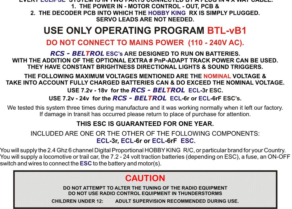
2 - 2 - INSTALLING RCS-BELTROL ESC s. HOBBY KING IS A GROUP B R/C & THIS ESC MUST USE THE BTLvB1 OPERATING PROGRAM. RCS-BELTROL ESC s can use a HK TR6a 6 channel 2.4 GHz digital proportional R/C TX & RX with servo outputs. We have conducted development & testing with both Mode # 1 & Mode # 2 systems. See page # 4. These have sprung Elevator & non sprung Throttle controls which are used to control the locomotive. The RCS-BELTROL program uses the L to R Aileron & Rudder sticks to trigger 4 x sound effects. The channel # 5 knob is used for initial speed calibration, making system program changes such as Start/Max voltage, default direction start, system reset & sound trigger outputs from momentary to latch ON - OFF See page # 7 for information as to how the TX sticks are used. LOCOMOTIVE SEPARATION. It is not necessary to separate 2.4 GHz R/C R/C systems with crystals. They are all legal for air & ground use. Every TX has a unique identifier code and any TR6a receiver (RX) can be BOUND to any HK T6a TX. BINDING must be done before the system can be used. Ideally it should be done before the RX is plugged into the # DEC-U pcb. However, if this is not possible, we have supplied a 3 way cable to temporarily join the RX to the # DEC-U before final installation. This will allow access to the BINDING socket on the RX for the BINDING plug supplied with the HK TR6a RX. See page # 4 for the BINDING procedure. Insert BINDING plug. Then place # EX-LD into any RX & DEC sockets. Orange to centre of pcb. Then follow page # 5. Remove the # EX-LD & binding plug before installing the RX into the # DEC-U. # DEC-U & Tr6a RX shown. You can mount the # DEC-U PCB with double stick tape or non conductive silicone. Do not allow metal objects to touch the rear of the PCB. Damage to the PCB may result. INSERTING THE HK-TR6a RX. The TR6a 2.4 GHz RX simply plugs into the # DEC-U upside down & eliminates all servo leads. Be careful locating the pins into the pcb sockets. You must accurately align the RX pins to the numbers shows It will be a stiff push fit, but do not force the RX home. The # DEC-U provides a 5 volt BEC supply for the 6 channel TR6a 2.4 GHz RX. You do not need batteries for the RX. Hold one part in each hand. Carefully line up pins # 1 6. Then gently press onto socket. The fit will be tight. Do not force. The BATTERY BIND terminals must NOT be connected.


3 - 3 - Alternately, the separately sold # DEC-ADAPT kit permits the RX to be mounted anywhere you wish. With the addition of the # BINDER, this kit will also enable you to have an at will BINDING capability to hand over locos to a different TX. EG. Adding & removing speed matched locos to a train. See page # & 3.2. Speed matching. The # DEC-ADPT kit. (Prototype kit shown). Insert the 1 x 3 way servo cable & four single wire cables into the TR6a RX. The 3 x wire cable goes to # 1 servo output. Carefully line up the # DEC-ADAPT pcb with pin # s 1-6 on the # DEC-A and gently press it home onto the pins. PLACING RX ANTENNA. Other than with brass locos, it does not matter where you place the antenna(s). We have range with the system in plastic locos. There is NO glitching or Rusty Bolt Effect. N.B. With metal locos the antenna may need to be vented externally to maximise range. Although there is evidence that 2.4 GHz RX s have been successfully used with the RX & antenna inside a dummy water tank of a live steam loco. Turn the TR6a 2.4 GHz TX OFF to save the batteries & the loco will Cruise along until the TX is turned ON again & manual control resumed. The RCS-BELTROL program ignores the Hobby King TR6a Fail safe. INSTALLING THE RCS-BELTROL ESC. Wiring diagrams for your specific ESC must be downloaded in pdf format from the RCS-BELTROL website. POWER SOURCES. You can use battery power. OR: Constant track voltage. See below. Maximum voltages for a particular ESC are shown on page # 1. BATTERY POWER. Connect the traction battery, which MUST BE FUSED, as per the wiring diagram. RCS-BELTROL R/C offers a variety of installation kits for on board use such as the # BIK-U3/6 which has screw terminals to simplify installations. For trail car installations we also have the # BIK-TC5. When used with the Bachmann K-27, we have a special kit, # BIK-K27 to simplify installation. PnP TRACK POWER. The # PnP-ADAPT is a Plug n Play pcb designed to be used with AristoCraft and Bachmann locos equipped with the standard PnP socket. It will collect constant track voltage which is then polarised, filtered, fused & connects to any ECLIPSE ESC w/screw terminals. Filtered DC is recommended. You may be able to use a non DC supply such as DCC. Battery back up of the track power is available via screw terminals on the # PnP-ADAPT. Make sure the battery pack is fully charged before using the system. NON PnP TRACK POWER. Contact RCS-BELTROL for advice on how to set up a bridge rectifier and filtering capacitors circuit. MOTOR CONNECTION. Connect the motor(s) as per the wiring diagrams. The M + motor output is positive (+) in a forward direction. In most installations the system will function perfectly well without any extra motor Noise suppression. The # ECL-PnP is a simple plug in installation. No wiring to the motors or lights. AristoCraft locos. We supply the # ECL-PnP programmed with the default pre-set to suit AristoCraft locos. Bachmann Spectrum Fn3 locos. You can easily reset the # ECL-PnP default direction to suit the Bachmann Spectrum Fn3 locos that have a PnP socket. See page # 6, 3.4 Default Direction. SHORT CIRCUIT & OVERLOAD PROTECTION. All RCS-BELTROL ESC s are self protecting. Although there is output overload & short circuit protection built into them, it is essential the track power & battery supply be fused for overall system protection. See the wiring diagram pages. RCS-BELTROL ESC s have transistor controlled directional lighting. Maximum current is 100 ma per terminal. IT IS MOST IMPORTANT THAT THE LIGHT BULBS BE COMPLETELY ISOLATED FROM ANY OTHER WIRING. Instead of rewiring some locos, sometimes it is much simpler to control the regular loco wiring by simply reversing the traction battery voltage. You can use the # RELAY-1a to do this as it can save a lot of wiring in many locos. It is especially useful in USA Trains locos to control incandescent bulbs or LED s up to 1 amp & smoke features. Please note: If the # RELAY-1a has been used, the lights will flash alternately, not together as with transistor outputs. When the system is in neutral only one set of lights will be lit. The instructions assume the operator has used the available front & rear transistor lighting outputs or # RELAY-v5. If you do not have any lighting outputs connected you MUST be able to observe the LED on the ESC.


. All the servo reversing switches must be set to normal.")

4 - 4 - SETTING UP THE RCS-BELTROL ESC s. THESE INSTRUCTIONS REFER TO THE HOBBY KING TR6a 2.4 GHz 6 CHANNEL R/C. LAYOUT OF THE HK-T6a TRANSMITTER. YOU CAN USE EITHER MODE # 1 or MODE # 2. YOUR SYSTEM WILL LIKELY BE DELIVERED CORRECTLY SET UP FOR THE MODE. HOWEVER IT IS A GOOD IDEA TO CHECK THE SETTINGS VIA THE SUPPLIED COMPUTER PROGRAM. SEE PAGE # 8. Shown above is a Mode # 1 TX. The Elevator & Rudder stick is on the left. The Throttle & Aileron stick is on the right Shown above is a Mode # 2 TX. The Elevator & Rudder stick is on the right. The Throttle & Aileron stick is on the left Prior to using this system there are two procedures that must be carried out by the operator. 1. BINDING. The 1st procedure is to BIND the CX-CR6a receiver (RX) to the Transmitter (TX). BINDING is accomplished by following a few simple steps that are outlined in the R/C system instructions. In case you don t have those instructions here is how we go about it. Although the RCS-BELTROL program ignores the RX Fail Safe commands, before BINDING the operator should nevertheless set up the failsafe as COPTER-X intended. The operator must have the spring loaded TX stick positions in neutral & the throttle stick to down (zero). All the servo reversing switches must be set to normal. (Only settable with the computer program). Firstly set up the TX trim tabs on all four control sticks. These MUST be in the middle. The HK T6a TX has regular slide type trim tabs. There is no Ch # 5 switch on the TX. Knob A must be rotated fully clockwise to be in the OFF position. The two switches A & B must be OFF. i.e pushed backwards away from you. They are not used. Once the trim tabs are in neutral you can proceed with the BINDING process. The TRIM tabs are easy to accidentally move. Re-centre them occasionally. No need to rebind. HOW TO BIND. 1.1 Firstly insert the BINDING plug supplied with the R/C system into the BINDING socket on the RX. This means gaining access to the RX. If the RX is buried inside the loco we recommend you use a servo extension lead or the # BINDER to get access. Press & hold the # BINDER pushbutton only when binding RX to TX. 1.2 Turn the loco power ON. The loco will always give a very slight jerk at switch ON. See page # 9. The RX LED will start blinking slowly to indicate it is ready to be bound. Please note the green LED on the ESC pcb & the front and rear lights (if fitted) will stay OFF. 1.3 Press the BINDING button on the TX and hold it in position. 1.4 Turn the TX power switch to ON. Almost immediately the LED on the RX will stop blinking & go solid ON. 1.5 Remove BINDING plug (or release # BINDER pushbutton) & store it safely. 1.6 Turn both loco & TX OFF. 1.7 Turn loco ON & the ESC LED & both loco lights will immediately blink three times & then go to solid ON. 1.8 The R/C system is ready for speed calibration.


 at the end of each stroke. Then return stick to zero (down position). 2.")

5 CALIBRATION. The 2 nd step in system preparation is to calibrate the direction & throttle sticks. Even though this step is only needed once when first setting up a new ESC, from time to time it is advisable to run through the procedure. 2.1 Turn ON the loco power. The RX LED, ESC LED & the loco lights stay OFF. 2.2 Set the HK-T6a Mode # 2 knob A on the TX To fully anti clockwise. i.e. rotate to the left. 2.3 Turn the TX ON. LED will illuminate. Make sure Throttle stick is down. Zero output. Almost immediately (between 2-3 seconds) RX & TX will recognise each other & the RX LED will come ON. The ESC LED & both front & rear lights will flash rapidly. 2.4 From zero (down position), gently stroke the Throttle stick backwards & forwards full travel a couple of times. Pause briefly (about 1 second) at the end of each stroke. Then return stick to zero (down position). 2.5 Gently stroke the Elevator stick backwards & forwards full travel a couple of times & let stick go. 2.6 Set the HK-T6a Mode # 2 knob A on the TX To fully clockwise. i.e. rotate to the right. The ESC LED & loco lights will immediately blink three times at a slower rate & both lights will go to solid ON. The system is in neutral and ready to operate. 2.7 Either turn the loco and TX OFF for later use, or proceed to SECTION 3 (PROGRAMMING) on page # 5.
6 PROGRAMMING. Operating features of the RCS-BELTROL system can be programmed from the TX by turning on CH # 5. Programming can only take place when the system is in neutral. 3.1 START VOLTAGE. This feature is designed to equalise the starting voltage of dissimilar locos. 3.2 TOP SPEED VOLTAGE. This can limit the top speed available. Either for speed matching locos or, for limiting the top speed of one loco, say for when the system is being operated by children. 3.3 MOMENTUM. Toggle momentum control ON or OFF. 3.4 DEFAULT DIRECTION. Reset the direction of a loco when it is to run back to back with another loco. 3.5 SYSTEM RESET. This takes # 1 & # 2 back to the factory default if incorrectly set. 3.6/7/8/9 SET SOUND TRIGGERS 1, 2, 3 & 4 from MOM (Default) to Latch ON - OFF. HOW TO USE THE PROGRAMMING FEATURE. Turn ON the loco power. The loco will give a slight jerk & the RX and loco lights will stay OFF. After switch ON, the system will be, & must stay, in neutral. If running, return to neutral before programming. Only turn the Ch # 5 knob ON AFTER the TX has been turned ON. Do not turn the Ch # 5 knob on first. SPEED MATCHING. If you have two or more locos that have dissimilar starting and top speeds, you can adjust those voltages so the locos will be fairly accurately speed matched across the speed range. It has been our experience that absolutely accurate matching is not really needed for smooth performance. The trade off is the top speed of a consist of locos controlled by one TX will be limited to the top speed of the slowest loco. 3.1 START VOLTAGE. We suggest you test the locos you wish to match one at a time to find out the stick setting at which the slowest starting locos begin to move. Count the number of clicks on the throttle stick from OFF (down). Then, with the slowest loco stopped and the direction set to neutral: Move the throttle stick to the loco start speed desired. i.e. to the stick position where the loco started moving. Then push the direction (elevator) stick forwards once only. The lights will blink ONCE with the push. Wait a couple of seconds for the lights to blink ONCE again indicating the new start voltage setting has been stored in the system memory. Then move the throttle stick back to zero (OFF) position. i.e. stick down. Then turn channel # 5 OFF. The lights will blink three times and then go to all solid ON. i.e. Neutral. Repeat the procedure if the setting is incorrect. 3.2 TOP SPEED VOLTAGE. If speed matching, we suggest you test the locos you wish to match one at a time to find out the stick setting at which the fastest loco matches the top speed of the slowest loco. Then, with the fastest loco stopped and the direction set to neutral: Move the throttle stick to the lower top speed desired for the loco. i.e. to the stick position where the fastest loco matched the top speed of the slowest loco. Then push the direction (elevator) stick forwards TWICE only. The lights will blink once with each push. Wait a couple of seconds for the lights to blink TWICE again indicating the new top speed voltage setting has been stored in the system memory. Then move the throttle stick back to zero (OFF) position. i.e. stick down. Then turn channel # 5 knob OFF. The lights will blink three times and then go to all solid ON. i.e. Neutral. Repeat the procedure if the setting is incorrect. OR: When children are using the loco, you can follow the same steps to limit the top speed of any loco. 3.3 MOMENTUM. Toggle momentum control ON or OFF. Press the elevator stick forwards THREE times only. The lights will blink once with each push. Wait a couple of seconds for the lights to blink THREE times again indicating the default momentum ON OFF setting has been stored in the system memory. Then turn channel # 5 knob OFF. The lights will blink three times and then go to all solid ON. i.e. Neutral. 3.4 DEFAULT DIRECTION. To re-set the default direction of a loco to run back to back with another loco: Push the direction (elevator) stick forwards FOUR times only. The lights will blink once with each push. Wait a couple of seconds for the lights to blink FOUR times again indicating the default direction setting has been stored in the system memory. Then turn channel # 5 knob OFF. The lights will blink three times and then go to all solid ON. i.e. Neutral. 3.5 SYSTEM RESET. To take # 3.1 & # 3.2 back to the factory default if incorrectly set: Push the direction (elevator) stick forwards FIVE times only. The lights will blink once with each push. Wait a couple of seconds for the lights to blink FIVE times again indicating the start & top speed voltage settings have been returned to default in the system memory. Then turn channel # 5 knob OFF. The lights will blink three times and then go to all solid ON. i.e. Neutral. 3.6/7/8/9 SET SOUND TRIGGERS 1, 2, 3 & 4 from MOM (Default) to Latch ON - OFF. For trigger # 1 Push the direction (elevator) stick forwards SIX times only. The lights will blink once with each push. Wait a couple of seconds for the lights to blink SIX times again, indicating the trigger has toggled to latch ON-OFF. Then turn channel # 5 knob OFF. The lights will blink three times and then go to all solid ON. i.e. Neutral. Repeat procedure for trigger # 2 (SEVEN pushes) trigger # 3 (EIGHT pushes) & trigger # 4 (NINE pushes). Repeat procedure to change any of the 4 x triggers back to MOMENTARY from Latch ON OFF.
7 - 7 - OPERATING THE RCS-BELTROL ESC s. 4. HOW TO OPERATE. N.B. The TX Ch # 5 knob must be OFF. i.e. clockwise. THE THROTTLE STICK MUST BE ALL THE WAY DOWN BEFORE TURNING SYSTEM ON. Always turn ON the loco first. The loco will give a slight jerk. See page # 9. The ESC & loco the lights will stay OFF. Then turn the TX ON. After between 2-8 seconds the TX & RX will recognise each other. The RX LED will come ON & not blink. The ESC LED & both front & rear loco lights (if fitted) will blink three times & then all lights will go to solid ON. N.B. In order to select a direction the throttle stick must be OFF and the system must be in neutral. 4.1 FORWARDS. To select forwards direction push the Elevator stick fully forwards once & then release it. The rear light will go out. The green LED on the ESC pcb & the front light will stay ON. If the # ECL ESC default motor & lights direction is incorrect please see TROUBLESHOOTING on page # SPEEDING UP. Gently push the Throttle stick forwards. The loco will accelerate away after 3-4 clicks. The speed is proportional to the stick position with a small amount of momentum built in to prevent sudden jerky movements. Let the stick go once the desired speed has been reached. The speed will stay the same until the Throttle stick is moved either up or down. Zero - Max speed takes 2 x seconds. Turn the HOBBY KING 2.4 GHz TX OFF to save the batteries & the loco will Cruise along until the TX is turned ON again & manual control resumed. The RCS-BELTROL program ignores the HOBBY KING Fail safe. 4.3 SLOWING DOWN. Pull the Throttle stick back to the desired speed. Max - Zero speed takes 2 x seconds. 4.4 STOPPING. Pull the Throttle stick back all the way back to stop. The ESC LED & front light will be ON. 4.5 REVERSE. You must completely stop the loco first. The Throttle stick must be all the way down. Then pull the Elevator stick fully back once & release it to return the system to neutral from forwards. The ESC LED plus both front and rear lights will be ON. Then pull the stick back again & release it. The ESC LED & front light will go out. The rear light will stay ON. To speed up, slow down & stop in reverse see SPEEDING UP, SLOWING DOWN & STOPPING above. CONTROLLING MOMENTUM & SOUND TRIGGERS. The RCS-BELTROL ESC s feature controllable momentum. An operator can control precisely how much or how little momentum effect is applied whilst accelerating and braking. The default is Momentum enabled. Momentum can either be ignored or switched off. See page # 6 - # 3.3 for how to switch momentum OFF. BRAKE RELEASE. Once direction has been set (see 4.1 above) pull the direction stick back (down) fully & HOLD stick in place. Then use the Throttle stick to set the speed you wish to attain. If you hold the direction stick down the loco will start to accelerate up to the set speed at the slowest rate of acceleration (30 seconds from zero to top speed). The acceleration rate is proportional to the stick position. Fully down = 30 seconds, half down = 15 seconds. Let the direction stick go & the loco will accelerate at the fastest rate (2 secs from zero to full speed) up to the set speed. BRAKE APPLY. Whilst the loco is running pull the direction stick all the way back (down) fully and HOLD stick in place. Then use the Throttle stick to set the speed to zero. If you hold the direction stick down the loco will start to decelerate to the set speed at the slowest rate of braking (30 seconds from top speed to zero). The braking rate is proportional to the stick position. Fully down = 30 seconds, half down = 15 seconds. If you let the stick go the loco will decelerate at the fastest rate (2 x seconds from full speed to zero). SOUND SYSTEM TRIGGERS. RCS-BELTROL ESC s have 4 x four manual sound triggers controlled by the sprung left to right Aileron & Rudder stick controls. Outlets are marked 1 4 on the row of 8 x screw terminals on the # DEC-U pcb. Max current is 100 ma. You can activate any sound with any trigger depending on which TX stick you want to operate the sound with. Mode # 1 & Mode # 2 sound triggers are both the same. RH stick to the left is F 1. RH stick to the right is F 2. LH stick to the left is F 4. LH stick to the right is F 3. The default for each is Momentary. All are programmable for latch ON OFF instead. See page # /7/8/9. If you prefer the trigger outputs the other way around, it is OK to reverse the Aileron & Rudder reversing switches. Do not reverse the THROTTLE & ELEVATOR switches. When using with Momentary function, press the stick until the sound is activated. Release stick to turn sound OFF. When using with a Latch ON OFF function, press and hold the stick for one second until the sound is activated. Then release the stick and the sound will stay ON. Press the same stick for one second & release to turn the sound OFF. They can be used as is with most sound systems such as Sierra, Phoenix, Dallee & MyLocosound. Sierra will require the additional purchase of one # SSI-12v5 so that Sierra can function correctly.
8 - 8 - RCS-BELTROL ESC MU ing LOCO CONSISTS. MULTIPLE LOCOS IN A CONSIST. The RCS-BELTROL ESC s are capable of MU ing multiple locos in one consist of locos. You can add as many speed matched locos to the loco consist, as you like. Each loco must be bound to the controlling TX. Follow the BINDING procedure described above on page # 4. If the loco to be added has already been speed calibrated, there is no need to repeat the calibration step. The RCS-BELTROL program permits reversing default direction & speed matching of locos. Settings for these features are stored in the ESC so that any loco can be acquired by any TX. See page # 6. HOW TO ADD LOCOS TO A CONSIST. Turn the first loco OFF. Turn the second loco ON and drive it into position. Turn the first loco back ON. The lock in feature of the system ensures the direction is set positively. Just make sure both locos are at zero output before changing direction. To make sure the direction is set correctly for all locos in a consist, press the direction stick twice from neutral. Once the direction is set it cannot accidentally change back to neutral. DELETING LOCOS FROM A CONSIST. Turn OFF the to be retained loco. Leave the to be deleted loco ON & drive it away, or, rebind it to a different TX for use by another operator. See page # 4. BELTROL ESC used with the current model QSI sound. DO NOT use the PWM ESC s. Only the RCS-BELTROL # ECL-6RF ESC can be used with a QSI sound system fitted to a PnP socket inside an AristoCraft loco. The # ECL-6RF controls QSI sound correctly with outstandingly smooth slow speed acceleration & braking. The only practical way to use it is in a trail car with the batteries etc. We recommend a minimum of 18 volts nominal. You can safely use up to 24 volts nominal. Simply connect the output of the RCS-BELTROL ESC to the pigtails on the back of the AristoCraft loco. For other brands of locos refer to the QSI instructions. The track pick ups MUST be disabled. You can use the QSI as delivered with default REGULATED THROTTLE CONTROL. We recommend resetting to STANDARD THROTTLE CONTROL with level 2 load BEFORE setting an idle voltage. The QSI sound system needs to have an idle voltage applied so that when the loco has stopped the sound system is kept alive. The RCS-BELTROL system can be programmed to do this. Here is how to do it. Once the TX & RX have been bound together you need to calibrate the loco speed as described on page # 4. Once calibrated you now need to set the idle voltage which in effect is the same as setting the start speed. With the loco switched on gradually apply throttle until the sound system comes ON. Note TX stick position Continue to carefully apply throttle until the loco just begins to move. Once again note the stick position. You need to decide at which point it is that best suits your application. We suggest the idle (i.e. start) voltage should be set midway between the two stick positions you have just determined. Once you have determined what the start voltage is to be, take the throttle stick back down to zero and set the direction to neutral. Now go into RCS-BELTROL programming mode (see page # 6 section 3.1.). After entering programming mode, set the throttle stick position as recommended above. Then push the direction (elevator) stick forwards once only. The lights will blink ONCE with the push. Wait a couple of seconds for the lights to blink ONCE again indicating the new start voltage setting has been stored in the system memory. Then move the throttle stick back to zero (OFF) position. i.e. Stick down. Then turn channel # 5 OFF. The lights will blink three times and then go to all solid ON. i.e. Neutral. The QSI sound system will come on and you are now ready to operate. CONTROLLING THE SPEED OF A QSI EQUIPPED LOCO. To control the loco see page # 7 section 4.1. etc. The loco will NOT jerk when power is switched ON. If the direction is wrong, simply swap over the two wires coming from MM on the RCS-BELTROL ESC. When stopped the sound will remain in idle. CAUTION. DO NOT CONNECT THE OUTPUT OF THE ESC TO ANY NON QSI EQUIPPED LOCOS. TRIGGERING THE QSI SOUND SYSTEM WHISTLE/HORN & BELL. You will need to fit the RCS-BELTROL # FLIPPER in series in the MM leads and connect the trigger to the appropriate terminal on the RCS-BELTROL ESC. See the special # FLIPPER wiring diagram. One or the other of the sideways sticks will trigger the output functions. Only one half of the stick is used. The stick should be moved one way very briefly to turn the Bell ON & very briefly again to turn the Bell OFF. Move the same stick the same way & hold it to play the Whistle/Horn. Let the stick go & the play will cease.
9 - 9 - RCS-BELTROL ESC TROUBLESHOOTING. No matter how carefully we think we have explained how to do things, we do acknowledge we might have made mistakes or omissions. Here are some possible problem situations to look out for. WHEN THE LOCO IS SWITCHED ON THERE IS A SLIGHT JERK. This is normal. The slight jerk indicates power is connected to the system and the IC has powered up. WHEN THE LOCO IS SWITCHED ON ACCESSORY OUTPUT # 1 MAY TRIGGER BRIEFLY. This is also normal. A sound system function connected to output # 1 may trigger. Our testing shows no sign of this actually happening with Phoenix and Sierra. But, it is possible. WHEN THE LOCO IS SWITCHED ON, ALL LIGHTS COME ON WITHOUT BLINKING & NOTHING WORKS. This can occur when the TX is switched ON after the loco, with the throttle stick not fully OFF (down). SOLUTION. Ensure the throttle stick is completely OFF. The lights will blink to indicate linking. THE LOCO DIRECTION SET STICK & OR SPEED CONTROL IS BACKWARDS. It is most important to ensure that the servo reversing switches are ALL set to normal. When the direction is set to forwards the front light must come ON. If it doesn t, reverse the elevator switch. OR: reverse thr lighting wiring at the screw terminals on the # DEC-U. If the lighting direction is correct but speed is backwards, you must reverse the wiring to the motor(s). WEIRD ESC BEHAVIOUR FOR NO APPARENT REASON. The most likely problems you meet will be when the Ch # 5 knob has been left ON or accidentally turned ON. SITUATION # 1. If, when the TX is first turned on & the lights blink rapidly, it is because the Ch # 5 knob is ON & the system has entered calibration mode. SOLUTION. Turn the TX OFF. Select the OFF position for the Ch # 5 knob & then turn TX back ON again. SITUATION # 2. You have been running, & for no apparent reason the lights all went out when you selected neutral, & you have no control. This means the Ch # 5 knob was turned ON during running and has entered programming mode. CAUTION do not move any control sticks as you may make a program change. SOLUTION. Before doing anything else, turn Ch # 5 knob to OFF & the system will revert to normal operation. SITUATION # 3. The system was working and for some reason you had a panic situation. You stopped the loco and switched TX off. When you switched back on the loco lights were flashing and you moved the sticks to try and move the loco and now nothing works. You have accidentally turned the Ch # 5 Knob ON at some stage and altered the original speed and direction calibration. SOLUTION. Recalibrate the system. See page # 4. DEFAULT START UP DIRECTION. When using the # PnP-ADAPT, the # ECL-3r & # ECL-6r ESC s are programmed to be the same as the AristoCraft on board TE. As such, the motor direction & lights for Bachmann PnP socket equipped locos will need to be reset. See page # 6 section 3.4. The PnP socket and lights are also wired backwards on some AristoCraft locos. In this case the default direction will also need to be reset. See page # 6 section 3.4. OR: You can simply swap over the wires at the # PnP-ADAPT screw terminals. PLEASE ADVISE US OF ANY OTHER PROBLEMS ENCOUNTERED & WE WILL INCLUDE THEM HERE.
10 CARE & FEEDING OF THE HOBBY KING TX. The HOBBY KING transmitter uses 8 x AA size batteries. Either Alkaline dry cells or rechargeables. We use Sanyo ENELOOP rechargeable AA cells which are guaranteed to hold 85% of their charge for 12 months if not being used. Always recharge them after the TX has been used for any length of time. It is most important to ensure the batteries always have plenty of charge in them when using the TX. If the LED is showing RED, the batteries are getting low. This may result in loss of control. If you have chosen to use Alkalines, we advise you to replace them immediately. Do not attempt to use the TX if the RED LED is lit. Always keep a spare set of batteries handy. HOBBY KING TX PROGRAMMING. HOBBYKING R/C systems are provided with a CD and USB cable so that the TX can be programmed to suit yourself. We strongly suggest you check the settings in your TX BEFORE attempting to use the system. Once the USB Serial port cable program and the T6config programs have been installed you can proceed. The TX must be connected to the computer and turned ON. Under SYSTEM OPTION select SETTING and choose a COM Port from the available list. Press OK. When the program is open the operator has the following programmable features under SYSTEM SETTING: END POINT: ALL 100%. REVERSE: ALL NORMAL. i.e. Leave the boxes unticked. SUB TRIM: ALL ZERO. DR: ALL ZERO. STICK: SELECT CORRECT STICK MODEL: = MODE #1 or MODE # 2. (MOST IMPORTANT). TYPE: SELECT ACRO. MIX: MIX # 1: SWITCH OFF. Or set it to throttle cut with Switch B. MIX # 2: Source = VRA. DES = CH 5. UP = 100%. DN = 100%. SWITCH = ON. MIX # 3: Source = VRB. DES = CH 6. UP = 100%. DN = 100%. SWITCH = ON. Always press OK after each step. SAVE = saves the programmed settings in the TX to a file in your computer. OPEN = opens the saved settings filed in your computer so they can be uploaded into a different TX. Instructions on how to set up and operate the COPTERX 6 channel R/C are available here: CAUTION: BIG FILE 9.10 Meg
INSTALLING RCS-BELTROL ESC s.
 - 2 - INSTALLING RCS-BELTROL ESC s. E-SKY IS A GROUP B R/C & THIS ESC MUST USE THE BTLvB1 OPERATING PROGRAM. RCS-BELTROL ESC s can use E-SKY ET61 6 channel 2.4 GHz digital proportional R/C. These instructions
INSTALLING RCS-BELTROL ESC s.
 - 2 - INSTALLING RCS-BELTROL ESC s. PLANET IS A GROUP A R/C & THIS ESC MUST USE THE BTLvA2 OPERATING PROGRAM. RCS-BELTROL R/C ESC s can use a PLANET T5 5 channel 2.4 GHz digital proportional R/C R6M RX
INSTALLING THE #OMEGA-3v9k ESC.
 - 2 - INSTALLING THE #OMEGA-3v9k ESC. We usually supply the # OMEGA-3v9k ESC with a Lemon brand Rx which is simply plugged in upside down on the ESC pcb in the 24 pin socket. The two parts are bench tested
INSTALLING THE #OMEGA-3v9s ESC.
 - 2 - INSTALLING THE #OMEGA-3v9s ESC. We usually supply the # OMEGA-3v9s ESC with a Lemon brand Rx which is simply plugged in upside down on the ESC pcb in the 24 pin socket. The two parts are bench tested
USE ONLY OPERATING PROGRAM BV1. DO NOT CONNECT TO MAINS POWER ( V AC).
.") P.O Box 578 Casino, NSW, 2470 Australia Phone: International ++614 2902 9083 Australia (04) 2902 9083 Website: http://rcs-rc.com E mail: Info@rcs-rc.com # PnP-3s Electronic Speed Controller FULL INSTRUCTION
P.O Box 578 Casino, NSW, 2470 Australia Phone: International ++614 2902 9083 Australia (04) 2902 9083 Website: http://rcs-rc.com E mail: Info@rcs-rc.com # PnP-3s Electronic Speed Controller FULL INSTRUCTION
INSTRUCTIONS. DO NOT CONNECT TO MAINS POWER ( V AC).
.") P.O Box 578 Casino, NSW, 2470 Australia Phone: International ++614 2902 9083 Australia (04) 2902 9083 Website: http://rcs-rc.com E mail: Info@rcs-rc.com OMEGA-3v5k Electronic Speed Controller FULL INSTRUCTION
P.O Box 578 Casino, NSW, 2470 Australia Phone: International ++614 2902 9083 Australia (04) 2902 9083 Website: http://rcs-rc.com E mail: Info@rcs-rc.com OMEGA-3v5k Electronic Speed Controller FULL INSTRUCTION
OMEGA-3v7 Electronic Speed Controller
 P.O Box 578 Casino, NSW, 2470 Australia Phone: International ++614 2902 9083 Australia (04) 2902 9083 Website: http://rcs-rc.com E mail: Info@rcs-rc.com OMEGA-3v7 Electronic Speed Controller FULL INSTRUCTION
OMEGA-3v8s Electronic Speed Controller
 P.O Box 578 Casino, NSW, 2470 Australia Phone: International ++614 2902 9083 Australia (04) 2902 9083 Website: http://rcs-rc.com E mail: Info@rcs-rc.com OMEGA-3v8s Electronic Speed Controller FULL INSTRUCTION
INSTRUCTIONS. DO NOT CONNECT TO MAINS POWER ( V AC).
.") P.O Box 578 Casino, NSW, 2470 Australia Phone: International ++614 2902 9083 Australia (04) 2902 9083 Website: http://rcs-rc.com E mail: Info@rcs-rc.com TABLE OF CONTENTS PROVIDED IN INSTRUCTIONS. Page
P.O Box 578 Casino, NSW, 2470 Australia Phone: International ++614 2902 9083 Australia (04) 2902 9083 Website: http://rcs-rc.com E mail: Info@rcs-rc.com TABLE OF CONTENTS PROVIDED IN INSTRUCTIONS. Page
INSTRUCTIONS. DO NOT CONNECT TO MAINS POWER ( V AC).
.") P.O Box 578 Casino, NSW, 2470 Australia Phone: International ++614 2902 9083 Australia (04) 2902 9083 Website: http://rcs-rc.com E mail: Info@rcs-rc.com ALPHA-3v2 Electronic Speed Controller Supplied for
P.O Box 578 Casino, NSW, 2470 Australia Phone: International ++614 2902 9083 Australia (04) 2902 9083 Website: http://rcs-rc.com E mail: Info@rcs-rc.com ALPHA-3v2 Electronic Speed Controller Supplied for
CAUTION DO NOT ATTEMPT TO ALTER THE TUNING OF THE RADIO EQUIPMENT. DO NOT USE RADIO CONTROL EQUIPMENT IN THUNDERSTORMS.
 P.O Box 578 Casino, NSW, 2470 Australia Phone: International ++614 2902 9083 Australia (04) 2902 9083 Website: http://rcs-rc.com E mail: info@rcs-rc.com TX-3 Digital Proportional R/C TABLE OF CONTENTS
TX-1 Digital Proportional R/C
 P.O Box 578 Casino, NSW, 2470 Australia Phone: International ++614 2902 9083 Australia (04) 2902 9083 Website: http://rcs-rc.com E mail: info@rcs-rc.com TX-1 Digital Proportional R/C TABLE OF CONTENTS
AUSTRALIA (04) PHONE: INTERNATIONAL # MRW-SSLS
 PHONE: INTERNATIONAL # MRW-SSLS") R/C SWITCHES PO BOX 8 BAYSWATER, VIC 353, AUSTRALIA PHONE: INTERNATIONAL ++64 2902 9083 AUSTRALIA (04) 2902 9083 Web: http://www.rcs-rc.com Email: rcs@rcs-rc.com # MRW-SSLS # MRW-SSLS by Model Radio Workshop
R/C SWITCHES PO BOX 8 BAYSWATER, VIC 353, AUSTRALIA PHONE: INTERNATIONAL ++64 2902 9083 AUSTRALIA (04) 2902 9083 Web: http://www.rcs-rc.com Email: rcs@rcs-rc.com # MRW-SSLS # MRW-SSLS by Model Radio Workshop
RR Concepts. The StationMaster can control DC trains or DCC equipped trains set to linear mode.
 Jan, 0 S RR Concepts M tation aster - 5 Train Controller - V software This manual contains detailed hookup and programming instructions for the StationMaster train controller available in a AMP or 0AMP
DTRx31d Instructions VERSION: GENERAL:
 DTRx31d Instructions DelTang YouTube Channel: http://www.youtube.com/user/now4dt DelTang website: http://www.deltang.co.uk The Rx31d is a 4 channel receiver unit for use with micro servos. To save weight
Warning! Before continuing further, please ensure that you have NOT mounted the propellers on the MultiRotor.
 Mission Planner Setup ( optional, do not use if you have already completed the Dashboard set-up ) Warning! Before continuing further, please ensure that you have NOT mounted the propellers on the MultiRotor.
30A BLDC ESC. Figure 1: 30A BLDC ESC
 30A BLDC ESC Figure 1: 30A BLDC ESC Introduction This is fully programmable 30A BLDC ESC with 5V, 3A BEC. Can drive motors with continuous 30Amp load current. It has sturdy construction with 2 separate
EtronixPulseRXInstructions 6/6/11 09:17 Page 1
 EtronixPulseRXInstructions 6/6/11 09:17 Page 1 EtronixPulseRXInstructions 6/6/11 09:17 Page 2 Etronix Pulse EX2 Sport 2 Channel 2.4GHz Steer Wheel Transmitter 1) INTRODUCTION. Thank you for choosing this
CAUTION-ELECTRICALLY OPERATED PRODUCT
 CAUTION-ELECTRICALLY OPERATED PRODUCT NOT RECOMMENDED FOR CHILDREN UNDER 14 YEARS OF AGE. AS WITH ALL ELECTRIC PRODUCTS, PRECAUTIONS SHOULD BE OBSERVED DURING HANDLING AND USE TO PREVENT ELECTRIC SHOCK.
Fitting Radio Control to a Mamod Boulton
 Fitting Radio Control to a Mamod Boulton How To Fit Radio Control To A Mamod Boulton using FlySky Equipment I assume that you already have a Mamod Boulton and have fitted rechargeable AA batteries instead
HYDRA 120 & HYDRA 240 OPERATION MANUAL
 HYDRA 120 & HYDRA 240 OPERATION MANUAL The battery connector must be added to the power side of the controller (black capacitors, receiver connector, and red and black wire side). The red wire is the positive
mz-12 & GR-18 Setup Tutorial
 mz-12 & GR-18 Setup Tutorial INTRODUCTION Thank you for purchasing the mz-12 COPTER radio. This radio is the first of its kind that lets you fly your multirotor without the need of complex setups, computer
PHOENIX Features of the Phoenix-25 : 2.3 Connecting the Motor. 2.4 Reversing Rotation. 2.5 Connecting the Receiver
 Warning! High power motor systems can be very dangerous! High currents can heat wires and batteries, causing fires and burning skin. Follow the wiring directions carefully! Model aircraft equipped with
Begin to Use The New ESC: Before use the new ESC please carefully check every connections are correct or not. Yellow motor wire B Blue motor wire A
 HIMOTO ZTW Brushless Electronic Speed Control for car or truck Thank you for purchasing ZTW Brushless Electronic Speed Controller(ESC). The ZTW electronic speed control (ESC) is specifically designed for
PHOENIX HV Features of the Phoenix HV-45 : 2.3 Connecting the Motor. 2.4 Reversing Rotation. 2.5 Connecting the Receiver
 PHOENIX HV -45 1.0 Features of the Phoenix HV-45 : Extremely Low Resistance (.003 ohms) High rate adjustable switching (PWM) Up to 45 Amps continuous current Dual Opto-Coupled (No BEC) Up to 36 cells or
PHOENIX Features of the Phoenix-10 : 2.3 Connecting the Motor. 2.4 Reversing Rotation. 2.5 Connecting the Receiver
 Warning! High power motor systems can be very dangerous! High currents can heat wires and batteries, causing fires and burning skin. Follow the wiring directions carefully! Model aircraft equipped with
Caution Notes. Features. Specifications. Installation. A3 3-axis Gyro & Stabilizer User Manual V1.0
 Caution Notes Thank you for choosing our products. If any difficulties are encountered while setting up or operating it, please consult this manual first. For further help, please don t hesitate to contact
Operation and Installation Manual
 Operation and Installation Manual G-Scale Graphics 4118 Clayton Ct. Fort Collins, CO 80525 970-581-3567 GScaleGraphics@comcast.net www.gscalegraphics.net Revision C: Updated 7/15/2009 Page Overview The
INSTALLATION MANUAL SPECTRUM BRAKE CONTROL
 INSTALLATION MANUAL 51170 SPECTRUM BRAKE CONTROL TABLE OF CONTENTS Controls & Components Tools List Before You Begin Wiring Wiring Diagram Mounting the LED Display Rotary Knob Wiring the Plug Connector
Features: Enhanced throttle response, excellent acceleration, linearity and driveability
 120A/150A ESC X-Car 120A/150A Series Sensored/Sensorless Brushless ESC for 1:8 scale Car or Truck Thank you for purchasing the X-Car Brushless Electronic Speed Controller (ESC). The X-Car 1:8 Scale 120A/150A
Model 1:8 Beast-ZTWSS120A 1:8 Beast-ZTWSS150A. PN#Model Cont.Current 120A 150A. Burst Current 760A 1080A
 Alien Power System BEAST Series Sensored/Sensorless Brushless ESC for 1:8 scale Car or Truck Thank you for purchasing the Alien Power System Brushless Electronic Speed Controller (ESC). The Alien Power
Azatrax MRX3 Grade Crossing Signal Controller Installation Guide
 Azatrax MRX3 Grade Crossing Signal Controller Installation Guide What it is: The MRX3 is a sophisticated controller that realistically operates model railroad / highway crossing signals. The MRX3 includes
When you finish the running, power off the receiver BEFORE turning off the transmitter.
 Thanks for purchasing Turnigy AQUASTAR ESC speed controllers. Turnigy AQUASTAR ESC are specifically developed to supply stable and strong power for r/c model boats beyond you expected. Please read the
Operation and Installation Manual
 Operation and Installation Manual G-Scale Graphics 5860 Crooked Stick Dr. Windsor, CO 80550 970-581-3567 GScaleGraphics@comcast.net www.gscalegraphics.net Revision A: Updated 2/7/2018 Page Overview The
PHOENIX ENIX Features of the Phoenix-60 : 2.3 Connecting the Motor. 2.4 Reversing Rotation. 2.5 Connecting the Receiver
 PHOENIX ENIX-60 Warning! High power motor systems can be very dangerous! High currents can heat wires and batteries, causing fires and burning skin. Follow the wiring directions carefully! Model aircraft
AS RW BEC TRUCK LIPO User Manual ver 1.00
 ` To Receiver AS-12-40 RW BEC TRUCK LIPO User Manual ver 1.00 5-12 Cell 40 A For/Rev 2 A BEC Batt - Motor- Reverse Light Batt + Brake Light Motor+ Features: Operating Voltage: 5-12 Nimh/Nicad Cells or
Galileo RADIO CONTROLLED QUAD-COPTER
 Galileo TM RADIO CONTROLLED QUAD-COPTER FEATURING: 1. Four-Rotor design allows great speed and maneuverability for both Indoor and Outdoor use. 2. Built-in 6-axis Gyro ensures excellent stability. 3. Modular
Features: Enhanced throttle response, excellent acceleration, strong brakes and throttle linearity. Using LED program card to make adjustments.
 Thank you for purchasing the ZTW Brushless Electronic Speed Controller (ESC). The ZTW 1:10 Scale BEAST Series ESC is specifically designed for operating 4 Pole Sensorless brushless motors. This is a high
PHOENIX Amp Brushless Sensorless Speed Control. 1.0 Features of the Phoenix-25 : 2.3 Connecting the Motor. 2.4 Reversing Rotation
 1.0 Features of the Phoenix-25 : Extremely Low Resistance (.013 ohms) High rate (7 KHz) switching (PWM) Up to 25 Amps continuous current with proper air flow, 35 amps surge Five to eight cells with four
(Designed & Manufactured by RC EXPLORER TEAM) Radon V2 series Brushless Speed Control System User Guidelines
 Radon V2 series Brushless Speed Control System User Guidelines") (Designed & Manufactured by RC EXPLORER TEAM) Radon V2 series Brushless Speed Control System User Guidelines 1. Technical /Specifications: Model: Radon Pro V2 Radon Pro V2 1S Radon Sport V2 Continuous
(Designed & Manufactured by RC EXPLORER TEAM) Radon V2 series Brushless Speed Control System User Guidelines 1. Technical /Specifications: Model: Radon Pro V2 Radon Pro V2 1S Radon Sport V2 Continuous
Auscision 48/830 Class DCC Operating Information
 Auscision 48/830 Class DCC Operating Information Your Auscision 48/830 class models main printed circuit board and associated lighting has been designed to function as a DC / DCC Ready and DCC Sound Decoder
Welcome to VBar Express 5.3
 Bar Express Welcome to VBar Express 5.3 The VBar with V 5.3 Express software is an innovative product setting new standards for model helicopters in terms of flight performance and programming capacity.
2 / 8 CLAYMORE SPEED BOAT
 The following terms are used throughout the product literature to indicate various levels of potential harm when operating this product: NOTICE: Procedures, which if not be properly followed, will create
MPI MX-9900 SUPER GLOW On-board Glow Driver
 MPI SUPER GLOW On-board Glow Driver Congratulations on your purchase of the SUPER-GLOW on-board glow driver. This an advanced on-board glow driver offering unique features. is very different from other
20/40/60A V2 Brushless Electronic Speed Controller INSTRUCTION MANUAL. Copyright 2013 KY MODEL Company Limited.
 20/40/60A V2 Brushless Electronic Speed Controller INSTRUCTION MANUAL www.copterx.com Copyright 2013 KY MODEL Company Limited. MENU 1. 2. 3. 4. 5. 6. 7. Table of content Introduction Specifications Programmable
USER MANUAL BRUSHLESS SPEED CONTROLLER S5-RTR ESC S5A-RTR ESC RC CARS & TRUCKS
 USER MANUAL BRUSHLESS SPEED CONTROLLER S5-RTR ESC S5A-RTR ESC RC CARS & TRUCKS Declaration Thanks for purchasing our Electronic Speed Controller (ESC). High power system for RC model can be very dangerous,
STEAM MYLOCOSOUND MAY 4 TH 2017
 1 STEAM MYLOCOSOUND MAY 4 TH 2017 UNIVERSAL SOUND FOR LARGE SCALE, DC, STEAM LOCOMOTIVES 1.OVERVIEW Easy installation using screw terminals with no soldering. Uses a TV remote control to adjust the volume
Locomotive decoder LE104XF 1
 Locomotive decoder LE104XF 1 The locomotive decoder LE104XF is suitable for all DC motors in HO scale locomotives with continuous current draw of 1.0 Amp or less. The characteristics of the decoder are:
NCE DCC TWIN. In addition to the NCE DCC TWIN, you will need:
 NCE DCC TWIN Welcome to the world of DCC! This manual will familiarize you with the set up and operation of two locomotives on your railroad using the NCE DCC TWIN. In addition to the NCE DCC TWIN, you
12 Locomotive decoder LE135 Locomotive decoder LE135 1
 12 Locomotive decoder LE135 Locomotive decoder LE135 1 for all repairs or replacements. Should the user desire to alter a Digital Plus Product, they should contact Lenz GmbH for prior authorization. Year
Owner and Operating Manual for
 Owner and Operating Manual for 120VAC Manual Control 12VDC Solar Battery Manual Control 120VAC Remote Control 12VDC Solar Battery Remote Control GEN2 Remote Versions Only Boat Lifts Please read this manual
Overview of operation modes
 Overview of operation modes There are three main operation modes available. Any of the modes can be selected at any time. The three main modes are: manual, automatic and mappable modes 1 to 4. The MapDCCD
Galileo with wifi RADIO CONTROLLED QUAD-COPTER
 Galileo with wifi TM RADIO CONTROLLED QUAD-COPTER FEATURING: 1. Four-Rotor design allows great speed and maneuverability for both Indoor and Outdoor use. 2. Built-in 6-axis Gyro ensures excellent stability.
4-CHANNEL RADIO CONTROLLED QUAD-COPTER
 DRONIUM TM 4-CHANNEL RADIO CONTROLLED QUAD-COPTER FEATURING: 1. Four-Rotor design allows great speed and maneuverability for both Indoor and Outdoor use. 2. Built-in 6-axis Gyro ensures excellent stability.
* Ql! ^0f. B-17 Flying Fortress. 3 axis stabilization
 G3&nw * Ql! ^0f B-17 Flying Fortress 3 axis stabilization (HK)EASYSKY ENTERPRISE LIMITED Website: www.easy-sky.net E-mail: rcmodel@easy-sky.net sales@easy-sky.net Tel: 86-755-27891 659 Fax:86-755-27372071
CAPTAIN AMERICA 2CH FLYING FIGURE IR HELICOPTER
 I N S T R U C T I O N M A N U A L ITEM NO: 33190 CAPTAIN AMERICA 2CH FLYING FIGURE IR HELICOPTER Stabilizer Bar Main Rotor Blades LED Light PRODUCT INCLUDES: - IR Helicopter - Remote - User Manual - Main
RATE CONTROLLED TORQUE WRENCH TESTER
 RATE CONTROLLED TORQUE WRENCH TESTER OPERATOR S HANDBOOK (PART NO. 34078) ISSUE 8 NORBAR TORQUE TOOLS LTD, Beaumont Road, Banbury, Oxfordshire, OX16 1XJ, UNITED KINGDOM Tel : + 44 (0) 1295 270333, Fax
TWO-WAY LCD AUTOMATIC TRANSMISSION REMOTE STARTER. User Guide
 TWO-WAY LCD AUTOMATIC TRANSMISSION REMOTE STARTER User Guide A note concerning the battery inside the transmitter: Depending on your usage of the transmitter, the battery can last anywhere between 3 to
INSTRUCTIONS SPECIAL FEATURES
 INSTRUCTIONS Discharge Termination: auto-cut based on individual cell voltages 2.75V per cell in Quick-Balance Mode 3.0V per cell in Interface Mode with separate discharger Discharge Current: 120mA per
Product Guide: Series III Pump Control Board Set (RoHS)
") revised 04/08/10 Description: The Series III Pump Control Board Set provides motor drive and pump control for a wide assortment of pumps from Scientific Systems, Inc. The assembly consists of two circuit
revised 04/08/10 Description: The Series III Pump Control Board Set provides motor drive and pump control for a wide assortment of pumps from Scientific Systems, Inc. The assembly consists of two circuit
RADIO CONTROLLED QUAD-COPTER WITH CAMERA
 Movie - DRONE TM RADIO CONTROLLED QUAD-COPTER WITH CAMERA FEATURING: 1. Four-Rotor design allows great speed and maneuverability for both Indoor and Outdoor use. 2. Built-in 6-axis Gyro ensures excellent
Three Function Remote Control System with Alarm (Model RCA-3)
") Golden RODtronics P.O. Box 146 Golden Colorado 80402-0146 Phone 303-423-8597 Fax 303-420-4575 Three Function Remote Control System with Alarm (Model RCA-3) Congratulations! You have just purchased one
Golden RODtronics P.O. Box 146 Golden Colorado 80402-0146 Phone 303-423-8597 Fax 303-420-4575 Three Function Remote Control System with Alarm (Model RCA-3) Congratulations! You have just purchased one
F-22 PACKING LIST INSTRUCTION MANUAL. 4.5 Channel
 F- 4.5 Channel INSTRUCTION MANUAL 4 PARTS - SERVICE - REPAIRS Open Mon - Fri 9 am - 6 pm... Sat 0 am - 3 pm (EST) Distributed and serviced by: Extreme RC by RSI... Ferndale, MI 480 Phone: (586) 757-336
Special Features. Specifications Motor Types: Sensored Motor Limit: 2.5T (on 2S) Input Voltage: 2-3S LiPo Direction: Forward, Brake, Reverse
 Input Voltage: 2-3S LiPo Direction: Forward, Brake, Reverse") MS-1 ELECTRONIC SPEED CONTROL Thank you for choosing TrakPower as your source for brushless electronics. The MS-1 ESC was specifically developed for 1/10th competition. The MS-1 ESC features an aluminum
MS-1 ELECTRONIC SPEED CONTROL Thank you for choosing TrakPower as your source for brushless electronics. The MS-1 ESC was specifically developed for 1/10th competition. The MS-1 ESC features an aluminum
Locomotive Driver Desk. Manual
 Locomotive Driver Desk Manual Authors: Dr.-Ing. T. Vaupel, D. Richter, M. Berger Translated by Wolfram Steinke Copyright Uhlenbrock Elektronik GmbH, Bottrop 3rd Edition March 2004 All Rights Reserved Duplication
AS-4000 OPERATING INSTRUCTIONS (PS-5000)
") AS-4000 OPERATING INSTRUCTIONS (PS-5000) BASIC OPERATIONS This unit is a state-of-the-art combination of a vehicle alarm and remote starter system. Start by familiarizing yourself with the alarm functions
AS-4000 OPERATING INSTRUCTIONS (PS-5000) BASIC OPERATIONS This unit is a state-of-the-art combination of a vehicle alarm and remote starter system. Start by familiarizing yourself with the alarm functions
FIRE PHOENIX RADIO CONTROLLED AIRPLANE
 FIRE PHOENIX RADIO CONTROLLED AIRPLANE ASSEMBLY AND OPERATION INSTRUCTIONS YIN YAN MODEL TECH. MFT. 1 SPECIFICATIONS Material EPO Plane Battery Li-Po 1300mAh 11.1V Radio 4 Channel Wing Span 1200mm Length
(Designed & Manufactured by RC EXPLORER TEAM) XPS Brushless Speed Control System User Guidelines
 XPS Brushless Speed Control System User Guidelines") (Designed & Manufactured by RC EXPLORER TEAM) XPS Brushless Speed Control System User Guidelines 1. Technical /Specifications: Model: XPS- Pro XPS-Sport XPS-EL Continuous current: 140A 70A 35A Burst Current
(Designed & Manufactured by RC EXPLORER TEAM) XPS Brushless Speed Control System User Guidelines 1. Technical /Specifications: Model: XPS- Pro XPS-Sport XPS-EL Continuous current: 140A 70A 35A Burst Current
COMPATIBLE MOTOR ASSEMBLY TYPES
 4908 McKenna Ct., Columbus, Ohio, 43221 USA (614) 876-6345 www.aircraftextras.com sales@aircraftextras.com INSTALLATION MANUAL THANK YOU!... for purchasing the FPS-Plus system from Aircraft Extras, Inc.
User Manual RC Electric Parts Electric Speed Controller (ESC) for Brushless Motors
 for Brushless Motors") User Manual RC Electric Parts Electric Speed Controller (ESC) for Brushless Motors Thank you for using RC Electric Parts ESC designed to meet your hobbies needs. As you'll find the ESC's settings are programmable
User Manual RC Electric Parts Electric Speed Controller (ESC) for Brushless Motors Thank you for using RC Electric Parts ESC designed to meet your hobbies needs. As you'll find the ESC's settings are programmable
User Instruction manual for Cardale Autoglide
 User Instruction manual for Cardale Autoglide NOTE TO INSTALLER: This user manual is supplied for the instruction of the end user. It contains important safety and warranty information. This manual MUST
User Guide 1 WAY FM MANUAL TRANSMISSION REMOTE STARTER. Table of Contents. Introduction
 1 WAY FM MANUAL TRANSMISSION REMOTE STARTER User Guide Table of Contents... 1 Introduction... 1 Using the Remote Control... 2 Multi-Level Features (default state)... 2 Remote-Starting Your Vehicle... 3
INSTRUCTIONS FOR TRI-METRIC BATTERY MONITOR May 8, 1996
 INSTRUCTIONS FOR TRI-METRIC BATTERY MONITOR May 8, 1996 PART 2: SUPPLEMENTARY INSTRUCTIONS FOR SEVEN TriMetric DATA MONITORING FUNCTIONS. A: Introduction B: Summary Description of the seven data monitoring
Multi-Rotor Series User Guide
 1 INTRODUCTION Multi-Rotor Series User Guide This manual provides instructions on incorporating your Castle Creations Multi-Rotor ESCs into your aircraft, from wiring and mounting your ESCs to configuring
S D ST215 TAFFOR. ST215 Temperature Programmer User Handbook.
 TAFFOR S D ST215 ST215 Temperature Programmer User Handbook www.staffordinstruments.co.uk See separate handbook for Installation Instructions Issue: 1.000 ST215 Copyright User Handbook 2014 Stafford Instruments
1) Wire Cutters 1) Solder (Rosin Core Electronic Solder) 2) Wire Strippers 2) Battery Connector 3) watt soldering iron
 Wire Cutters 1) Solder (Rosin Core Electronic Solder) 2) Wire Strippers 2) Battery Connector 3) watt soldering iron") Thank you for purchasing the Electronic Speed Control (ESC). The V-Series ESC Line was designed to offer high power and high efficiency combined with low weight and a compact size. These instructions will
Thank you for purchasing the Electronic Speed Control (ESC). The V-Series ESC Line was designed to offer high power and high efficiency combined with low weight and a compact size. These instructions will
INSTALLATION GUIDE Table of Contents
 CT-3100 Automatic transmission remote engine starter systems. What s included..2 INSTALLATION GUIDE Table of Contents Door lock toggle mode..... 4 Notice...2 Installation points to remember. 2 Features..2
BX88175 Installation Instructions ToadStop II Vacuum Brake System
 BX88175 Installation Instructions ToadStop II Vacuum Brake System Serial No. Customer supplied tools & supplies Utility knife, 12VDC tester, drill & bits: (1/8", 1/4", 5/8 ), ¼ socket drive bit, punch,
Climber is 776B101101
 is Climber 776B101101 Introduction Product Introduction NE R/C 776B is a good-sized glider designed by Nine Eagles Company latest, whose wing span is up to 2008mm. You only need to assemble the aerofoil
 Introduction Thank you for purchasing a Redcat JETiger Ducted-Fan Aircraft! Headquartered in Phoenix, AZ; Redcat Racing is proud to have become the premier source for quality Gas, Nitro and Electric powered
Kelly KDC Series/PM Motor Controller User s Manual
 Kelly KDC Series/PM Motor Controller User s Manual KDC48600 KDC48601 KDC48602 KDC48603 KDC72600 KDC72601 KDC72602 KDC72603 KDC72800 KDC72801 KDC72802 KDC72803 KDC12602 KDC12603 Rev.3.3 May 2011 Contents
NOS -36 Magic. An electronic timer for E-36 and F1S Class free flight model aircraft. January This document is for timer version 2.
 NOS -36 Magic An electronic timer for E-36 and F1S Class free flight model aircraft January 2017 This document is for timer version 2.0 Magic Timers Copyright Roger Morrell January 2017 January 2017 Page
SK-GPS Instruction Manual. Rev August 1, 2014
 SK-GPS Instruction Manual Rev. 1.10 August 1, 2014 Table of Contents Safety...1 Box Contents...2 Getting Started...3 SK-GPS Internal Blue LED States...3 Swash Bump at Init...3 Mounting the SK-GPS...4 Connecting
H-King R/C scale model series. instruction manual
 H-King R/C scale model series instruction manual 1. Please read this manual carefully and follow the instructions of the manual before you use this products. SAFETY INSTRUCTIONS 2. Our airplane is not
IMPORTANT! Remote Control Instructions
 Remote Control Instructions FOR New Tarp Remote Control Installation Use these in place of the rocker switch and solenoid section of instructions in your roll tarp owner s manual. FOR Existing Electric
Cirtix series Brushless Speed Controller manual For RS1/RS A/ Page - 1 -
 RS1/RS20602010A/100524 Page - 1 - Thank you for purchasing the Speed Passion Cirtix series electronic speed controller (ESC). High power systems for RC models can be very dangerous, so we strongly suggest
GETTING STARTED EASY TO USE, SOPHISTICATED ENOUGH TO WIN EVERYTHING. You are now ready to go!
 WARNING: This is an extremely powerful brushless motor system. We strongly recommend removing the pinion gear from the motor for your own safety and the safety of those around you before performing calibration
Model AX-510 Owner s Manual
 Model AX-510 Owner s Manual 4 Button Remote Security System with Dual Stage Shock Sensor IMPORTANT! In order to provide the highest possible level of security to your vehicle, this system is equipped with
Parker AC10 Frequency Inverter (to 22kW) Easy Start Guide
 Easy Start Guide") Parker AC10 Frequency Inverter (to 22kW) Easy Start Guide CAUTION: 1)Do not re-set while the motor is rotating 2)Perform parts replacement after discharge is finished 3)Do not connect output terminals
Parker AC10 Frequency Inverter (to 22kW) Easy Start Guide CAUTION: 1)Do not re-set while the motor is rotating 2)Perform parts replacement after discharge is finished 3)Do not connect output terminals
25A and 50A Industrial Bi-Directional DC Speed Control Rev by Motion Dynamics Instructions for Installation and Operation (v1.
 25A and 50A Industrial Bi-Directional DC Speed Control Rev 3.2 2015 by Motion Dynamics Instructions for Installation and Operation (v1.03) HAZARD Warning! The heat sink used in this controller may get
USER MANUAL FOR ATLAS HO DUAL-MODE 4-FUNCTION DCC DECODER (ITEM #342)
") HO Dual-Mode 4-Function Decoder 1 USER MANUAL FOR ATLAS HO DUAL-MODE 4-FUNCTION DCC DECODER (ITEM #342) By Dual Mode, we mean that the Atlas #342 HO 4-function decoder has a jumper plug that allows the
HO Dual-Mode 4-Function Decoder 1 USER MANUAL FOR ATLAS HO DUAL-MODE 4-FUNCTION DCC DECODER (ITEM #342) By Dual Mode, we mean that the Atlas #342 HO 4-function decoder has a jumper plug that allows the
elabtronics Voltage Switch
 elabtronics Voltage Switch Want to trigger a device when a monitored voltage, temperature or light intensity reaches a certain value? The elabtronics Voltage Switch is an incredibly easy way of doing it.
ECT Display Driver Installation for AP2 Module
 ECT Display Driver Installation for AP2 Module Overview The ECT Display Driver is a small module with a removable wire harness that mounts behind the driver's foot well cover. All wiring connections are
The RCS-6V kit. Page of Contents. 1. This Book 1.1. Warning & safety What can I do with the RCS-kit? Tips 3
 The RCS-6V kit Page of Contents Page 1. This Book 1.1. Warning & safety 3 1.2. What can I do with the RCS-kit? 3 1.3. Tips 3 2. The principle of the system 2.1. How the load measurement system works 5
Radio control glider
 Radio control glider Contents SPECIFICATIONS 01 STATEMENT 02 SAFETY PRECAUTIONS 02~03 CHARGING METHOD AND CAUTIONS 03~05 ASSEMBLY 06~07 2.4GHz RADIO SYSTEM 08~10 PRE-FLIGHT INSPECTION AND ADJUSTMENT 10~11
1100MM P-51 Mustang ELECTRIC POWERED REMOTE CONTROL AIRPLANE ELEVENHOBBY.COM
 1100MM P-51 Mustang ELECTRIC POWERED REMOTE CONTROL AIRPLANE ELEVENHOBBY.COM WARNING: Read the ENTIRE instruction manual to become familiar with the features of the product before operating. Failure to
SPIDER-MAN 2CH IR HEROCOPTER
 SPIDER-MAN 2CH IR HEROCOPTER I N S T R U C T I O N M A N U A L ITEM NO: 34896 Stabilizer Bar Main Rotor Blades LED Light BOTTOM VIEW PRODUCT INCLUDES: - IR Helicopter - Transmitter - User Manual - Spare
Very Fun & Easy NOTICE
 Very Fun & Easy NOTICE NOTICE All instructions, warranties and other collateral documents are subject to change at the sole discretion of our company. For up-to-date product literature, Visit our website
INSTALLATION MANUAL AP60B INSTALLATION MANUAL
 INSTALLATION MANUAL 2. TOOLS REQUIRED The following is a list of tools required to properly install the cruise control. While this unit may be installed without some of the tools listed, it is recommended