ABAQUS project Design and Analysis of a Composite Drive Shaft for an Automobile Dr.Taheri Armin Kianfar
|
|
|
- Philomena Gray
- 6 years ago
- Views:
Transcription
1 IN THE NAME OF GOD ABAQUS project Design and Analysis of a Composite Drive Shaft for an Automobile Dr.Taheri Armin Kianfar Summer of 2016

2 Contents Abstract Introduction Background Design of Steel Drive Shaft Design of Composite Drive Shaft MATLAB result Finite Element Analysis With Abaqus Abaqus result Conclusions References Appendix (MATLAB code)
3 Abstract In this paper an attempt has been made for analyzing of composite drive shafts for power transmission applications. The one-piece composite drive shaft is designed to replace conventional steel drive shaft of an automobile using E-glass / epoxy and high modulus (HM) carbon/epoxy composites.(this paper just analyze Carbon/Epoxy shaft!). The first generation of composite drive shafts all exist of propshafts. These are the drive shafts in longitudinal direction of the automobile. The advantages of composite propshafts compared to their steel equivalents include: minimised weight with superior tensile strength, virtually no thermal expansion of the composite shaft and corrosion resistance. Side shafts are the drive shafts between the differential and the wheels. Up to now, no production automobile is known that has ever made use of a fibre reinforced plastic composite side shaft. Although, it can be expected that the application of such a drive shaft will give benefits comparable to those for the propshaft. Cost and end-fitting attachments seem to be the major problems for the application. The major points of attention during the whole design process are the maximum applied torque, the natural frequency, and the torsional stiffness.(in this paper we just analyze the torque effect!!!). The design of the composite drive shaft is split up into three parts: the design of the composite tube, the design of the adhesive bonded connection, and the design of the complete drive shaft that includes the steel end-fittings
4 Introduction The advanced composite materials such as Graphite, Carbon, Kevlar and Glass with suitable resins are widely used because of their high specific strength (strength/density) and high specific modulus (modulus/density). Advanced composite materials seem ideally suited for long, power driver shaft (propeller shaft) applications. Their elastic properties can be tailored to increase the torque they can carry as well as the rotational speed at which they operate. The drive shafts are used in automotive, aircraft and aerospace applications. The automotive industry is exploiting composite material technology for structural components construction in order to obtain the reduction of the weight without decrease in vehicle quality and reliability. It is known that energy conservation is one of the most important objectives in vehicle design and reduction of weight is one of the most effective measures to obtain this result. Actually, there is almost a direct proportionality between the weight of a vehicle and its fuel consumption, particularly in city driving. Description of the Problem Almost all automobiles (at least those which correspond to design with rear wheel drive and front engine installation) have transmission shafts. The weight reduction of the drive shaft can have a certain role in the general weight reduction of the vehicle and is a highly desirable goal, if it can be achieved without increase in cost and decrease in quality and reliability. It is possible to achieve design of composite drive shaft with less weight to increase the first natural frequency of the shaft and to decrease the bending stresses using various stacking sequences. By doing the same, maximize the torque transmission and torsional buckling capabilities are also maximized. Aim and Scope of the Work This work deals with the replacement of a conventional steel drive shaft with E-Glass/ Epoxy, High Strength Carbon/Epoxy and High Modulus Carbon/Epoxy composite drive shafts for an automobile application. Analysis Molding of the high strength carbon/epoxy composite drive shaft using ABAQUS.
5 Background Composites consist of two or more materials or material phases that are combined to produce a material that has superior properties to those of its individual constituents. The constituents are combined at a macroscopic level and or not soluble in each other. The main difference between composite and an alloy are constituent materials which are insoluble in each other and the individual constituents retain those properties in the case of composites, where as in alloys, constituent materials are soluble in each other and forms a new material which has different properties from their constituents. Classification of Composites Composite materials can be classified as Polymer matrix composite Metal matrix composite Ceramic Matrix Technologically, the most important composites are those in which the dispersed phase is in the form of a fiber. The design of fiber-reinforced composites is based on the high strength and stiffness on a weight basis. Specific strength is the ratio between strength and density. Specific modulus is the ratio between modulus and density. Fiber length has a great influence on the mechanical characteristics of a material. The fibers can be either long or short. Long continuous fibers are easy to orient and process, while short fibers cannot be controlled fully for proper orientation. Long fibers provide many benefits over short fibers.these include impact resistance, low shrinkage, improved surface finish, and dimensional stability. However, short fibers provide low cost, are easy to work with, and have fast cycle time fabrication procedures. The characteristics of the fiberreinforced composites depend not only on the properties of the fiber, but also on the degree to which an applied load is transmitted to the fibers by the matrix phase. The principal fibers in commercial use are various types of glass, carbon, graphite and Kevlar. All these fibers can be incorporated into a matrix either in continuous lengths or in discontinuous lengths as shown in the Fig 1. The matrix material may be a plastic or rubber polymer, metal or

6 ceramic. Laminate is obtained by stacking a number of thin layers of fibers and matrix consolidating them to the desired thickness. Fiber orientation in each layer can be controlled to generate a wide range of physical and mechanical properties for the composite laminate. Fig1. Types of fibers Advantages of Fiber Reinforced Composites High strength to weight ratio High stiffness to weight ratio High impact resistance Better fatigue resistance Improved corrosion resistance Good thermal conductivity Low Coefficient of thermal expansion. As a result, composite structures may exhibit a better dimensional stability over a wide temperature range.
7 Limitations of composites Mechanical characterization of a composite structure is more complex than that of a metallic structure The design of fiber reinforced structure is difficult compared to a metallic structure, mainly due to the difference in properties in directions The fabrication cost of composites is high Rework and repairing are difficult They do not have a high combination of strength and fracture toughness as compared to metals They do not necessarily give higher performance in all properties used for material selection Applications of Composites The common applications of composites are extending day by day. Nowadays they are used in medical applications too. The other fields of applications are, Automotive : Drive shafts, clutch plates, engine blocks, push rods, frames, Valve guides, automotive racing brakes, filament-wound fuel tanks, fiber Glass/Epoxy leaf springs for heavy trucks and trailers, rocker arm covers, suspension arms and bearings for steering system, bumpers, body panels and doors Aircraft: Drive shafts, rudders, elevators, bearings, landing gear doors, panels and floorings of airplanes etc. Space: payload bay doors, remote manipulator arm, high gain antenna, antenna ribs and struts etc. Marine: Propeller vanes, fans & blowers, gear cases, valves &strainers, condenser shells. Chemical Industries: Composite vessels for liquid natural gas for alternative fuel vehicle, racked bottles for fire service, mountain climbing, under ground storage tanks, ducts and stacks etc. Electrical & Electronics: Structures for overhead transmission lines for railways, Power line insulators, Lighting poles, Fiber optics tensile members etc.
 The torque that is produced from the engine and transmission must be transferred to the rear wheels to push the vehicle forward and reverse.")
8 Sports Goods: Tennis rackets, Golf club shafts, Fishing rods, Bicycle framework, Hockey sticks, Surfboards, Helmets and others. Purpose of the Drive Shaft (or Propeller shaft) The torque that is produced from the engine and transmission must be transferred to the rear wheels to push the vehicle forward and reverse. The drive shaft must provide a smooth, uninterrupted flow of power to the axles. The drive shaft and differential are used to transfer this torque. Functions of the Drive Shaft Fig First, it must transmit torque from the transmission to the differential gear box. 2. During the operation, it is necessary to transmit maximum low-gear torque developed by the engine. 3. The drive shafts must also be capable of rotating at the very fast speeds required by the vehicle. 4. The drive shaft must also operate through constantly changing angles between the transmission, the differential and the axles. As the rear wheels roll over bumps in the road, the differential and axles move up and down. This movement changes the angle between the transmission and the differential.
9 5. The length of the drive shaft must also be capable of changing while transmitting torque. Length changes are caused by axle movement due to torque reaction, road deflections, braking loads and so on. A slip joint is used to compensate for this motion. The slip joint is usually made of an internal and external spline. It is located on the front end of the drive shaft and is connected to the transmission. Different Types of Shafts 1. Transmission shaft: These shafts transmit power between the source and the machines absorbing power. The counter shafts, line shafts, overhead shafts and all factory shafts are transmission shafts. Since these shafts carry machine parts such as pulleys, gears etc., therefore they are subjected to bending moments in addition to twisting. 2. Machine Shaft: These shafts form an integral part of the machine itself. For example, the crankshaft is an integral part of I.C.engines slider-crank mechanism. 3. Axle: A shaft is called an axle, if it is a stationary machine element and is used for the transmission of bending moment only. It simply acts as a support for rotating bodies. Application: To support hoisting drum, a car wheel or a rope sheave. 4. Spindle: A shaft is called a spindle, if it is a short shaft that imparts motion either to a cutting tool or to a work-piece. Applications: 1. Drill press spindles-impart motion to cutting tool (i.e.) drill. 2. Lathe spindles-impart motion to work-piece.
10 Drive Shaft Arrangement in a Car Model Conventional two-piece drive shaft arrangement for rear wheel vehicle driving system is shown in figure 3 below. Figure 3 Conventional two-piece drive shaft arrangement for rear wheel vehicle driving system
11 Demerits of a Conventional Drive Shaft 1. They have less specific modulus and strength. 2. Increased weight. 3. Conventional steel drive shafts are usually manufactured in two pieces to increase the fundamental bending natural frequency because the bending natural frequency of a shaft is inversely proportional to the square of beam length and proportional to the square root of specific modulus. Therefore the steel drive shaft is made in two sections connected by a support structure, bearings and U-joints and hence over all weight of assembly will be more. 4. Its corrosion resistance is less as compared with composite materials. 5. Steel drive shafts have less damping capacity Merits of Composite Drive Shaft 1 They have high specific modulus and strength. 2 Reduced weight. 3 The fundamental natural frequency of the carbon fiber composite drive shaft can be twice as high as that of steel or aluminium because the carbon fiber composite material has more than 4 times the specific stiffness of steel or aluminium, which makes it possible to manufacture the drive shaft of passenger cars in one piece. A one-piece composite shaft can be manufactured so as to satisfy the vibration requirements. This eliminates all the assembly, connecting the two piece steel shafts and thus minimizes the overall weight, vibrations and the total cost. 4 Due to the weight reduction, fuel consumption will be reduced. 5 They have high damping capacity hence they produce less vibration and noise. 6 They have good corrosion resistance. 7 Greater torque capacity than steel or aluminium shaft. 8 Longer fatigue life than steel or aluminium shaft. 9 Lower rotating weight transmits more of available power.
12 Design of Steel Drive Shaft Specification of the Problem The fundamental natural bending frequency for passenger cars, small trucks, and vans of the propeller shaft should be higher than 6,500 rpm to avoid whirling vibration and the torque transmission capability of the drive shaft should be larger than 3,500 Nm. The drive shaft outer diameter should not exceed 100 mm due to space limitations. Here outer diameter of the shaft is taken as 90 mm. The drive shaft of transmission system is to be designed optimally for following specified design requirements as shown in Table1. Table 1 Design requirements and specifications Name Notation Unit value 1 Ultimate Torque Tmax Nm Max. speed of shaft Nmax rpm Length of shaft L mm 1250
13 Steel (SM45C) used for automotive drive shaft applications. The material properties of the steel (SM45C) are given in Table 2 The steel drive shaft should satisfy three design specifications such as torque transmission capability, buckling torque capability and bending natural frequency. Table.2 Mechanical properties of Steel (SM45C) Mechanical peroperties Symbol Units Steel Young s Modulus E GPa 207 Shear modulus G GPa 80 Poisson s ratio ν Density ρ Kg/m Yield Strength Sy MPa 370 Shear Strength Ss MPa ----
14 Torque Transmission capacity of the Drive Shaft Torsional Buckling Capacity of the Drive Shaft For long shaft the critical stress is, given by : For short and medium shaft the critical stress is, given by : The relation between the torsional buckling capacity and critical stress is given by :
15 Design of a Composite Drive Shaft Specification of the Problem The specifications of the composite drive shaft of an automotive transmission are same as that of the steel drive shaft for optimal design. Assumptions 1. The shaft rotates at a constant speed about its longitudinal axis. 2. The shaft has a uniform, circular cross section. 3. The shaft is perfectly balanced, i.e., at every cross section, the mass center coincides with the geometric center. 4. All damping and nonlinear effects are excluded. 5. The stress-strain relationship for composite material is linear & elastic; hence, Hooke s law is applicable for composite materials. 6. Acoustical fluid interactions are neglected, i.e., the shaft is assumed to be acting in a vacuum. 7. Since lamina is thin and no out-of-plane loads are applied, it is considered as under the plane stress. Selection of Cross-Section The drive shaft can be solid circular or hollow circular. Here hollow circular cross-section was chosen because: The hollow circular shafts are stronger in per kg weight than solid circular. The stress distribution in case of solid shaft is zero at the center and maximum at the outer surface while in hollow shaft stress variation is smaller. In solid shafts the material close to the center are not fully utilized.
16 Selection of Reinforcement Fiber Fibers are available with widely differing properties. Review of the design and performance requirements usually dictate the fiber/fibers to be used [1, 2]. Carbon/Graphite fibers: Its advantages include high specific strength and modulus, low coefficient of thermal expansion, and high fatigue strength. Graphite, when used alone has low impact resistance. Its drawbacks include high cost, low impact resistance, and high electrical conductivity. Glass fibers: Its advantages include its low cost, high strength, high chemical resistance, and good insulating properties. The disadvantages are low elastic modulus, poor adhesion to polymers, low fatigue strength, and high density, which increase shaft size and weight. Also crack detection becomes difficult. Kevlar fibers: Its advantages are low density, high tensile strength, low cost, and higher impact resistance. The disadvantages are very low compressive strength, marginal shear strength, and high water absorption. Kevlar is not recommended for use in torque carrying application because of its low strength in compression and shear. Here carbon fibers are selected as potential materials for the design of shaft. Selection of Resin System The important considerations in selecting resin are cost, temperature capability, elongation to failure and resistance to impact (a function of modulus of elongation). The resins selected for most of the drive shafts are either epoxies or vinyl esters. Here, epoxy resin was selected due to its high strength, good wetting of fibers, lower curing shrinkage, and better dimensional stability.
17 Selection of Materials Based on the advantages discussed earlier, the E-Glass/Epoxy, High Strength Carbon/Epoxy and High Modulus Carbon/Epoxy materials are selected for composite drive shaft. The Table 3 shows the properties of the E-Glass/Epoxy, High Strength Carbon/Epoxy and High Modulus Carbon/Epoxy materials used for composite drive shafts. Table 3 Properties of E-Glass/Epoxy, HS Carbon/Epoxy and HM Carbon/Epoxy S1.NO Property Unit E Glass /epoxy Hs Carbon /epoxy Hm Carbon /epoxy 1 E11 GPa E22 GPa G12 GPa ν S t1 = S c1 MPa S t2 = S C2 MPa S12 MPa ρ Kg /m Factor of Safety The designer must take into account the factor of safety when designing a structure. Since, composites are highly orthotropic and their fractures were not fully studied the factor of safety was taken as 2.
18 Torque Transmission Capacity of the Shaft Stress-Strain Relationship for Unidirectional Lamina The lamina is thin and if no out-of-plane loads are applied, it is considered as the plane stress problem. Hence, it is possible to reduce the 3-D problem into 2- D problem. For unidirectional 2-D lamina, the stress-strain relationship is given by, Stress-Strain Relationship for Angle-ply Lamina The relation between material coordinate system and X-Y-Z coordinate system is shown in Fig 4.Coordinates 1, 2, 3 are principal material directions and coordinates X, Y, Z are transformed or laminate axes.
19 Figure 4 Relation between material coordinate system and X-Y coordinate system For an angle-ply lamina where fibers are oriented at an angle with the positive X-axis (Longitudinal axis of shaft), the effective elastic properties are given by, The variation of the Exlamina, Eylamina and Gxylamina with ply orientation is shown in Fig 5 and 6 respectively.
20
21 The stress strain relationship for an angle-ply lamina is given by,
22 Where i,j=1,2,6 [A],[B],[D] matrices are called the extensinal, coupling, and bending stiffness matrices respectivly. We have :
23 For symmetric laminate, the B matrix vanishes and the in plane and bending stiffness are uncoupled. For symmetric laminate :
24 Where : When the shaft is subjected to torque T, the resultant forces in the laminate by considering the effect of centrifugal forces are: Nx = 0 Ny = 2ρt 2 r 2 Nz = T 2πr 2
25 Stresses in the k th ply are given by : Knowing the stresses in each ply, the failure of the laminate is determined by using the First Ply Failure criteria. That is, the laminate is assumed to fail when the first ply fails. Here maximum stress theory is used to find the torque transmitting capacity. Torsional Buckling Capacity (Tcr) Since long thin hollow shafts are vulnerable to torsional buckling, the possibility of the torsional buckling of the composite shaft was checked by the expression for the torsional buckling load Tcr of a thin walled orthotropic tube, which was expressed below [40]. This equation has been generated from the equation of isotropic cylindrical shell and has been used for the design of drive shafts.
26 MATLAB AND ABAQUS RESULT MATLAB Result
27 composite used in this paper is HM carbon /epoxy HM carbon /epoxy property Dimension table
28 Stacking sequence : [ 65/25/68/ 63/36/ 40/ 39/74/ 39 ] s N = 9725 rpm T =3700 N. m
29 The critical result form dept.of mech.engineering,psg college of technology,india: Critical result from MATALB code

30 Error Average of error = % Tsia wu failure theory for critical T :
31 Finite Element Analysis With Abaqus

32 In this section we analyze a drive shaft under those assumption said before: 1 st Step: Part Module

33 According to the given geometry in the paper we define a 3D deformable shell model with extrusion type! Then we sketch a circle as the shaft cross section.


34 Now, we should give the shaft depth.as you see it is 1.25m.

35 2 nd Step: Property Module First, we should define the material property in create material window. To define the model properties we follow these steps: The properties is extracted from the paper

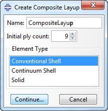
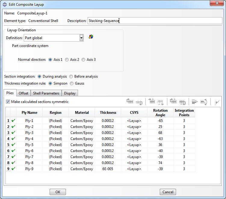
36 Next, we should define a stacking sequence like what comes in the paper. [ 65/25/68/ 63/36/ 40/ 39/74/ 39] s To make stacking sequence we selected the Create Composite Layup! Then we selected the conventional shell and pressed the continue!
37


38 Now we can see the stacking sequence in below pictures! 3 rd Step: Assembly Module


39 In this step we should bring the model in the assembly module! 4 th Step: Step Module In the Step module we follow the below path! Create Step >>Static General
40 5 th Step: Interaction Module Nothing to do!!! Because we have no Interaction!!!


41 6 th Step: Load Module Now, we need to define the specified Torque on the model.to do that we follow this : Create Load >> Shell Edge Load >> Selecting Shell Edges >> Entering the Torque Magnitude >> Press Ok!!!

42 To find the magnitude equivalent to the Critical Torque in the paper we should multiply the magnitude by the area of the edge!!! After that, the magnitude calculated was 6.4 E6!!!


43 7 th Step: Mesh Module As you see the color of the model is yellow.it says that we can use the Sweep Mesh in this model. To generate a sweep mesh on the part, we follow this procedure: Seed Part Instance >> Choose Approximate Global Size (0.02) >>Press OK Mesh Part Instance >> Select The Geometry >> Press Yes
44 After that the model is Meshed!!!

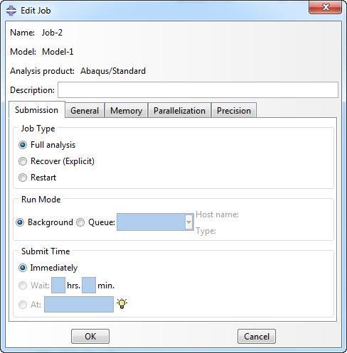
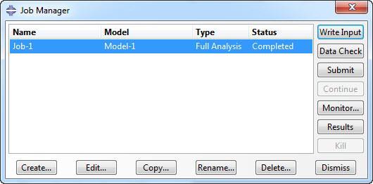
45 8 th Step : Job Module In this step we should only create a job to start analysis of the model. To do this the only work we have to do is: Press Create Job >> Press Ok >> Press Continue Now with pressing the SUBMIT button the analysis starts. if there is no problem in previous Steps, after sometime the complete message is seen in status column.
46

47 9 th Step : Visualization Module After analyzing the model, in this module we see the results. In the picture below you see the deformed shaft under the critical torque with the scale factor of about 16 times greater!

48
49 ABAQUS Result Average of error = 5.68 % Stress table layer S11 S22 S E E E E E E E E E E E E E E E E E E E E E E E E E E E+06
50 Stress E E E E E Stress E E E E E E E E E Stress E E E E E E E Series1 2.50E E E E E E E E E+07
51 Stress E E E E E E E E Stress E+02.50E E E+01.30E E E E+05.80E Conclusion In this paper after analyzing a composite shaft with numerical & finite element software (Matlab & Abaqus) and comparing the results with the source paper we conclude that the numerical solution had about 14% average error and about 6% for finite element analysis.
52 References [1]. T.Rangaswamy, S. Vijayarangan, R.A. Chandrashekar, T.K. Venkatesh and K.Anantharaman," OPTIMAL DESIGN AND ANALYSIS OF AUTOMOTIVE COMPOSITE DRIVE SHAFT", Dept. of Mech. Engineering, PSG College of Technology, Coimbatore , India,2007 [2]. A.R. Abu Talib a, Aidy Ali b,*, Mohamed A. Badie a, Nur Azida Che Lah b, A.F. Golestaneh b,"developing a hybrid, carbon/glass fiber-reinforced, epoxy composite automotive drive shaft" [3]. Mahmood M. Shokrieh a, Akbar Hasani a, Larry B. Lessard b, "Shear buckling of a composite drive shaft under torsion" a )Composites Research Laboratory, Mechanical Engineering Department, Iran University of Science and Technology, Narmak, Tehran 16844, Iran b) Mechanical Engineering Department, McGill University, 817 Sherbrooke St.W., Montreal, Qc, Canada H3A 2K6 [4]. Mehdi Hosseini, Mohammad Shariyat"Torsional Buckling Analysis of a Vehicle Composite Drive Shaft Based on a High OrderTheory with Considering Initial Imperfection" [5] M.A.K. Chowdhuri *1, R.A. Hossain 21 DepartmentofMechanicalEngineering,University of Alberta Edmonton, AB, Canada2 University of AlbertaEdmonton, AB, Canada "Design Analysis of an Automotive Composite DriveShaft" [6]. M. A. Badie 1, A. Mahdi 2, A. R. Abutalib 2, E. J. Abdullah 2 and R. Yonus 3 "AUTOMOTIVE COMPOSITE DRIVESHAFTS: INVESTIGATION OF THE DESIGN VARIABLES EFFECTS " 1 Department of Mechanical Engineering, Universiti Putra Malaysia, 43400, Serdang, Selangor, Malaysia 2 Department of Aerospace Engineering, Universiti Putra Malaysia. 3 Department of Chemical and Environmental Engineering, Universiti Putra Malaysia.
FAILURE ANALYSIS AND EVALUATION OF A COMPOSITE MATERIAL AUTOMOTIVE DRIVESHAFT BY USING FEM A REVIEW
 Int. J. Mech. Eng. & Rob. Res. 2014 Amol B Rindhe and S R Wagh, 2014 Research Paper ISSN 2278 0149 www.ijmerr.com Vol. 3, No. 2, April 2014 2014 IJMERR. All Rights Reserved FAILURE ANALYSIS AND EVALUATION
Design & Analysis of Composite Shaft of Passenger Vehicle
 International Research Journal of Engineering and Technology (IRJET) e-issn: 2395-56 : 4 Issue: 8 Aug -217 www.irjet.net p-issn: 2395-72 Design & Analysis of Composite Shaft of Passenger Vehicle Mr. A.R.
STATIC, MODAL AND BUCKLING ANALYSIS OF AUTOMOTIVE COMPOSITE DRIVE SAHFT Kishor Ghatage 1, Narayanrao Hargude 2
 IOSR Journal of Mechanical and Civil Engineering (IOSR-JMCE) ISSN: 2278-1684, PP: 32-42 www.iosrjournals.org STATIC, MODAL AND BUCKLING ANALYSIS OF AUTOMOTIVE COMPOSITE DRIVE SAHFT Kishor Ghatage 1, Narayanrao
Design and Experimental Investigation of an Automotive Hybrid Aluminium Composite Drive Shaft
 Design and Experimental Investigation of an Automotive Hybrid Aluminium Composite Drive Shaft Sunilkumar M. Bandgar 1, Nitin N. More 2 P.G. Student, Department of Mechanical Engineering, SKNSITS, Lonavala,
Design of Carbon/Epoxy Composite Drive Shaft for Low Passenger Vehicles
 International Journal of Current Engineering and Technology E-ISSN 2277 4106, P-ISSN 2347 5161 2016 INPRESSCO, All Rights Reserved Available at http://inpressco.com/category/ijcet Research Article Design
Design and Analysis of Composite Propeller Shaft for Automotive Application
 ISSN 2395-1621 Design and Analysis of Composite Propeller Shaft for Automotive Application #1 Dattatray S. Ghorpade, #2 Kishor B. Kale 1 dattatrayg218@gmail.com 2 kishorkale.iisc@gmail.com #12 Mechanical
Structural and Modal Analysis of Composite Material Shaft with Damping Material
 IJIRST International Journal for Innovative Research in Science & Technology Volume 2 Issue 06 November 2015 ISSN (online): 2349-6010 Structural and Modal Analysis of Composite Material Shaft with Damping
STATIC AND FATIGUE ANALYSIS OF LEAF SPRING-AS A REVIEW
 STATIC AND FATIGUE ANALYSIS OF LEAF SPRING-AS A REVIEW Vishal Gavali 1, Mahesh Jadhav 2, Digambar Zoman 3 1,2, 3 Mechanical Engineering Department, LGNSCOE Anjaneri Nashik,(India) ABSTRACT In engineering
FEA Based Vibration Characteristic Analysis of Conventional and Composite Material Single Piece Drive Shaft
 , July 5-7, 2017, London, U.K. FEA Based Vibration Characteristic Analysis of Conventional and Composite Material Single Piece Drive Shaft Ashwani Kumar, Neelesh Sharma, Pravin P Patil Abstract The main
Design And Analysis Of Two Wheeler Front Wheel Under Critical Load Conditions
 Design And Analysis Of Two Wheeler Front Wheel Under Critical Load Conditions Tejas Mulay 1, Harish Sonawane 1, Prof. P. Baskar 2 1 M. Tech. (Automotive Engineering) students, SMBS, VIT University, Vellore,
DESIGN AND ANALYSIS OF LEAF SPRING
 DESIGN AND ANALYSIS OF LEAF SPRING 1 Mr. RAJA MANAS MACHERLA, 2 Mr. SRIKANTH BAJAJ 1 Bachelor of technology, Department of MECH, Mahatma Gandhi Institute of Technology, Gandipet Main Road, Kokapet, Hyderabad,
DESIGN AND ANALYSIS OF PUSH ROD ROCKER ARM SUSPENSION USING MONO SPRING
 Volume 114 No. 9 2017, 465-475 ISSN: 1311-8080 (printed version); ISSN: 1314-3395 (on-line version) url: http://www.ijpam.eu ijpam.eu DESIGN AND ANALYSIS OF PUSH ROD ROCKER ARM SUSPENSION USING MONO SPRING
Vibration Analysis of Hybrid Composite Leaf Spring
 Vibration Analysis of Hybrid Composite Leaf Spring S.B. Jadhav 1, Prof. A.V. Karande 2 1 DGOI, FOE, Bhigvan, Pune, Maharashtra India, 2 Prof., DGOI, FOE, Bhigvan, Pune, Maharashtra India ABSTRACT This
Analysis of Composite Materials with Abaqus
 Analysis of Composite Materials with Abaqus Day 1 Lecture 1 Lecture 2 Lecture 3 Workshop 1 Lecture 4 Workshop 2a Workshop 2b Workshop 3 Introduction Macroscopic Modeling Mixed Modeling The Pagano Plate
Numerical Analysis and Optimization of Passenger Car Drive Shaft
 Numerical Analysis and Optimization of Passenger Car Drive Shaft Naveenkumar Dasanagoudar 1, Vinayak Koppad 2 1 Naveenkumar Dasanagoudar, Post graduate student of M.Tech (Machine Design), S T J Institute
Structural Analysis of Differential Gearbox
 Structural Analysis of Differential Gearbox Daniel Das.A Seenivasan.S Assistant Professor Karthick.S Assistant Professor Abstract- The main aim of this paper is to focus on the mechanical design and analysis
IJRASET: All Rights are Reserved
 Failure Analysis and Design Modification of Propeller Shaft of Bus Sweety P. Mhaske¹, Nitin P. Doshi² PG Scholar Mechanical Engg, Bapurao Deshmukh College of Engg & Technology, Sevagram, Wardha, Maharashtra,
VEHICLE ANTI-ROLL BAR ANALYZED USING FEA TOOL ANSYS
 VEHICLE ANTI-ROLL BAR ANALYZED USING FEA TOOL ANSYS P. M. Bora 1, Dr. P. K. Sharma 2 1 M. Tech. Student,NIIST, Bhopal(India) 2 Professor & HOD,NIIST, Bhopal(India) ABSTRACT The aim of this paper is to
DESIGN OF MACHINE MEMBERS - I
 R10 Set No: 1 III B.Tech. I Semester Regular and Supplementary Examinations, December - 2013 DESIGN OF MACHINE MEMBERS - I (Mechanical Engineering) Time: 3 Hours Max Marks: 75 Answer any FIVE Questions
ISSN: [Raghunandan* et al., 5(11): November, 2016] Impact Factor: 4.116
![ISSN: [Raghunandan* et al., 5(11): November, 2016] Impact Factor: 4.116](/thumbs/75/72421287.jpg "ISSN: [Raghunandan* et al., 5(11): November, 2016] Impact Factor: 4.116") IJESRT INTERNATIONAL JOURNAL OF ENGINEERING SCIENCES & RESEARCH TECHNOLOGY DESIGN AND ANALYSIS OF GO-KART CHASSIS D.Raghunandan*, A.Pandiyan, Shajin Majeed * Mechanical Department, Final year, Saveetha
IJESRT INTERNATIONAL JOURNAL OF ENGINEERING SCIENCES & RESEARCH TECHNOLOGY DESIGN AND ANALYSIS OF GO-KART CHASSIS D.Raghunandan*, A.Pandiyan, Shajin Majeed * Mechanical Department, Final year, Saveetha
Finite Element Analysis and optimization of Automotive Composite Drive Shaft
 Finite Element Analysis and optimization of Automotive Composite Drive Shaft S V Gopals Krishna* 1, B V Subrahmanyam 2, and R Srinivasulu 3 1&2 Asst. Professor, Sir C R Reddy College of Engineering, Eluru,
RTM COMPOSITE LUGS FOR HIGH LOAD TRANSFER APPLICATIONS
 25 TH INTERNATIONAL CONGRESS OF THE AERONAUTICAL SCIENCES RTM COMPOSITE LUGS FOR HIGH LOAD TRANSFER APPLICATIONS Markus Wallin*, Olli Saarela*, Barnaby Law**, Tommi Liehu*** *Helsinki University of Technology,
MODELLING AND STRUCTURAL ANALYSIS OF VEHICLE CHASSIS FRAME MADE OF POLYMERIC COMPOSITE MATERIAL
 MODELLING AND STRUCTURAL ANALYSIS OF VEHICLE CHASSIS FRAME MADE OF POLYMERIC COMPOSITE MATERIAL Shaik Neelophar Begum 1, S.P.Bhanu Murthy 2 1Department of Mechanical Engineering, VEMU Institute of Technology,
Finite Element Modeling and Analysis of Vehicle Space Frame with Experimental Validation
 Finite Element Modeling and Analysis of Vehicle Space Frame with Experimental Validation Assoc. Prof Dr. Mohammed A.Elhaddad Mechanical Engineering Department Higher Technological Institute, Town of 6
International Engineering Research Journal Analysis of HCV Chassis using FEA
 International Engineering Research Journal Special Edition PGCON-MECH-017 International Engineering Research Journal Nikhil Tidke 1, D. H. Burande 1 PG Student, Mechanical Engineering, Sinhgad College
Advanced Vehicle Performance by Replacing Conventional Vehicle Wheel with a Carbon Fiber Reinforcement Composite Wheel
 Advanced Vehicle Performance by Replacing Conventional Vehicle Wheel with a Carbon Fiber Reinforcement Composite Wheel Jyothi Prasad Gooda Technical Manager Spectrus Informatics Pvt..Ltd. No. 646, Ideal
LIGHTWEIGHT GEISLINGER GESILCO SHAFT
 LIGHTWEIGHT GEISLINGER GESILCO SHAFT GEISLINGER GESILCO SHAFT The Geislinger Gesilco shaft product range is based on more than 20 years experience in developing fibre composite couplings and shafts. The
OPTIMIZATION & ANANLYSIS OF A HEAVY VEHICAL CHASSIS USING COMPOSITE MATERIALS
 OPTIMIZATION & ANANLYSIS OF A HEAVY VEHICAL CHASSIS USING COMPOSITE MATERIALS U.NANDINI 1, C.PARIMALA 2, K.SAI KEERTHI 3 1,2,3 Assist. professor, department of mechanical engineering, Anantha Lakshmi Institute
ISSN: [Patil et al., 5(10): October, 2016] Impact Factor: 4.116
![ISSN: [Patil et al., 5(10): October, 2016] Impact Factor: 4.116](/thumbs/83/88212336.jpg "ISSN: [Patil et al., 5(10): October, 2016] Impact Factor: 4.116") IJESRT INTERNATIONAL JOURNAL OF ENGINEERING SCIENCES & RESEARCH TECHNOLOGY DESIGN AND ANALYSIS OF TELESCOPIC HALFSHAFT FOR AN ALL-TERRAIN VEHICLE (ATV) Chirag Patil *, Sandeep Imale, Kiran Hiware, Sumeet
IJESRT INTERNATIONAL JOURNAL OF ENGINEERING SCIENCES & RESEARCH TECHNOLOGY DESIGN AND ANALYSIS OF TELESCOPIC HALFSHAFT FOR AN ALL-TERRAIN VEHICLE (ATV) Chirag Patil *, Sandeep Imale, Kiran Hiware, Sumeet
UNIT-3 PART-A C.K.GOPALAKRISHNAN, AP/MECH, MAHALAKSHMI ENGINEERING COLLEGE, TRICHY
 UNIT-3 PART-A 1. List the loads normally acting on a shaft? Bending load Torsional load or tw isting load. Axial thrust. 2. Write dow n the expression for the power transmitted by a shaft. P=2π NT/60 Where
DESIGN OF A MODIFIED LEAF SPRING WITH AN INTEGRATED DAMPING SYSTEM FOR ADDED COMFORT AND LONGER LIFE
 DESIGN OF A MODIFIED LEAF SPRING WITH AN INTEGRATED DAMPING SYSTEM FOR ADDED COMFORT AND LONGER LIFE Sean D Silva 1, Sumit Jain 2 1, 2 Department of Mechanical Engineering, Rajiv Gandhi Institute of Technology,
DEPARTMENT OF MECHANICAL ENGINEERING
 DEPARTMENT OF MECHANICAL ENGINEERING UABMCC01-DESIGN OF MACHINE ELEMENTS QUESTION BANK Prepared By: Dr.S.Prabhakaran, Associate Professor/Mechanical Engg. Unit -1 STEADY STRESSES AND VARIABLE STRESSES
DESIGN AND ANALYSIS OF COMPOSITE DRIVE SHAFT
 DESIGN AND ANALYSIS OF COMPOSITE DRIVE SHAFT KETHAVATH RAJESH Mr.A.RAMESH(M.Tech) Asst.Professor SDEPARTMENT OF MECHANICAL ENGINEERING MALLA REDDY ENGINEERING COLLEGE (AUTONOMOUS) (An Autonomous Institution
IJESRT. Scientific Journal Impact Factor: (ISRA), Impact Factor: METHODOLOGY Design Parameter [250]
![IJESRT. Scientific Journal Impact Factor: (ISRA), Impact Factor: METHODOLOGY Design Parameter [250]](/thumbs/93/112194125.jpg "IJESRT. Scientific Journal Impact Factor: (ISRA), Impact Factor: METHODOLOGY Design Parameter [250]") IJESRT INTERNATIONAL JOURNAL OF ENGINEERING SCIENCES & RESEARCH TECHNOLOGY DESIGN AND ANALYSIS OF COMPOSITE LEAF SPRING FOR LIGHT COMMERCIAL VEHICLE (TATA ACE) Miss. Gulshad Karim Pathan*, Prof. R.K.Kawade,
IJESRT INTERNATIONAL JOURNAL OF ENGINEERING SCIENCES & RESEARCH TECHNOLOGY DESIGN AND ANALYSIS OF COMPOSITE LEAF SPRING FOR LIGHT COMMERCIAL VEHICLE (TATA ACE) Miss. Gulshad Karim Pathan*, Prof. R.K.Kawade,
MODELING SUSPENSION DAMPER MODULES USING LS-DYNA
 MODELING SUSPENSION DAMPER MODULES USING LS-DYNA Jason J. Tao Delphi Automotive Systems Energy & Chassis Systems Division 435 Cincinnati Street Dayton, OH 4548 Telephone: (937) 455-6298 E-mail: Jason.J.Tao@Delphiauto.com
A STUDY ON THE PROPELLER SHAFT OF CAR USING CARBON COMPOSITE FIBER FOR LIGHT WEIGHT
 International Journal of Mechanical Engineering and Technology (IJMET) Volume 9, Issue 5, May 2018, pp. 603 611, Article ID: IJMET_09_05_066 Available online at http://www.iaeme.com/ijmet/issues.asp?jtype=ijmet&vtype=9&itype=5
OPTIMIZATION AND MODIFICATION OF LEAF SPRING USING FEA ANALYSIS
 OPTIMIZATION AND MODIFICATION OF LEAF SPRING USING FEA ANALYSIS Shivangi Patel 1, Tejal Patel 2 M.E. Student (CAD/CAM) 1, Assistant Professor 2 Hasmukh Goswami College of Engineering, Gujarat, India ABSTRACT
DESIGN AND ANALYSIS OF THE COMPOSITE SPUR GEAR
 DESIGN AND ANALYSIS OF THE COMPOSITE SPUR GEAR Anuj Nath 1, A.R. Nayak 2 1 M.Tech Student, 2 Assistant Professor, Mechanical Engineering, Swamy Vivekananda Engineering College, Bobbili A.P (India) ABSTRACT
Design and Stress Analysis of Crankshaft for Single Cylinder 4-Stroke Diesel Engine
 Design and Stress Analysis of Crankshaft for Single Cylinder 4-Stroke Diesel Engine Amit Solanki #1, Jaydeepsinh Dodiya #2, # Mechanical Engg.Deptt, C.U.Shah University, Wadhwan city, Gujarat, INDIA Abstract
PIONEER RESEARCH & DEVELOPMENT GROUP
 Design and Stress Analysis of Tow Bar for Medium Sized Portable Compressors Pankaj Khannade 1, Akash Chitnis 2, Gangadhar Jagdale 3 1,2 Mechanical Department, University of Pune/ Smt. Kashibai Navale College
Design, analysis and mounting implementation of lateral leaf spring in double wishbone suspension system
 Design, analysis and mounting implementation of lateral leaf spring in double wishbone suspension system Rahul D. Sawant 1, Gaurav S. Jape 2, Pratap D. Jambhulkar 3 ABSTRACT Suspension system of an All-TerrainVehicle
Analysis of Composite Materials with Abaqus 6.14
 Analysis of Composite Materials with Abaqus 6.14 About this Course Course objectives Upon completion of this course you will be able to: Define anisotropic elasticity for combining the fiber-matrix response
Load Analysis and Multi Body Dynamics Analysis of Connecting Rod in Single Cylinder 4 Stroke Engine
 IJSRD - International Journal for Scientific Research & Development Vol. 3, Issue 08, 2015 ISSN (online): 2321-0613 Load Analysis and Multi Body Dynamics Analysis of Connecting Rod in Single Cylinder 4
 DEPARTMENT OF MECHANICAL ENGINEERING Subject code: ME6601 Subject Name: DESIGN OF TRANSMISSION SYSTEMS UNIT-I DESIGN OF TRANSMISSION SYSTEMS FOR FLEXIBLE ELEMENTS 1. What is the effect of centre distance
THE LONGITUDINAL VIBRATION OF COMPOSITE DRIVE SHAFT
 THE LONGITUDINAL VIBRATION OF COMPOSITE DRIVE SHAFT Tongtong Zhang, Yongsheng Li, Weibo Wang National Key Laboratory on Ship Vibration and Noise, China Ship Scientific Research Centre, Wuxi, China email:
Performance Testing of Composite Bearing Materials for Large Hydraulic Cylinders
 TECHNICAL Performance Testing of Composite Bearing Materials for Large Hydraulic Cylinders Leo Dupuis, Bosch-Rexroth Sr. Development Engineer Introduction Large hydraulic cylinders (LHCs) are integral
New Frontier in Energy, Engineering, Environment & Science (NFEEES-2018 ) Feb
 Feb") RESEARCH ARTICLE OPEN ACCESS DESIGN AND IMPACT ANALYSIS OF A ROLLCAGE FOR FORMULA HYBRID VEHICLE Aayush Bohra 1, Ajay Sharma 2 1(Mechanical department, Arya College of Engineering & I.T.,kukas, Jaipur)
RESEARCH ARTICLE OPEN ACCESS DESIGN AND IMPACT ANALYSIS OF A ROLLCAGE FOR FORMULA HYBRID VEHICLE Aayush Bohra 1, Ajay Sharma 2 1(Mechanical department, Arya College of Engineering & I.T.,kukas, Jaipur)
COMPARATIVE ANALYSIS OF CRANKSHAFT IN SINGLE CYLINDER PETROL ENGINE CRANKSHAFT BY NUMERICAL AND ANALYTICAL METHOD
 COMPARATIVE ANALYSIS OF CRANKSHAFT IN SINGLE CYLINDER PETROL ENGINE CRANKSHAFT BY NUMERICAL AND ANALYTICAL METHOD Mr. Anant B. Khandkule PG Student Mechanical Engineering Department, Sinhgad Institute
EFFECT OF TYRE OVERLOAD AND INFLATION PRESSURE ON ROLLING LOSS & FUEL CONSUMPTION OF AUTOMOBILES CARS
 EFFECT OF TYRE OVERLOAD AND INFLATION PRESSURE ON ROLLING LOSS & FUEL CONSUMPTION OF AUTOMOBILES CARS D.MADHUSUDHANA 1 C. NAGARAJA 2 PG Student Assistant Professor Dept. of Mechanical Engineering Dept.
Composite Long Shaft Coupling Design for Cooling Towers
 Composite Long Shaft Coupling Design for Cooling Towers Junwoo Bae 1,#, JongHun Kang 2, HyoungWoo Lee 2, Seungkeun Jeong 1 and SooKeun Park 3,* 1 JAC Coupling Co., Ltd., Busan, South Korea. 2 Department
Abaqus Composites Tutorial
 Abaqus Composites Free PDF ebook Download: Abaqus Composites Download or Read Online ebook abaqus composites tutorial in PDF Format From The Best User Guide Database Design and Sizing composites structures
Application of ABAQUS to Analyzing Shrink Fitting Process of Semi Built-up Type Marine Engine Crankshaft
 Application of ABAQUS to Analyzing Shrink Fitting Process of Semi Built-up Type Marine Engine Crankshaft Jae-Cheol Kim, Dong-Kwon Kim, Young-Duk Kim, and Dong-Young Kim System Technology Research Team,
Chapter 7: Thermal Study of Transmission Gearbox
 Chapter 7: Thermal Study of Transmission Gearbox 7.1 Introduction The main objective of this chapter is to investigate the performance of automobile transmission gearbox under the influence of load, rotational
STRUCTURAL DESIGN AND ANALYSIS OF ELLIPTIC CYCLOCOPTER ROTOR BLADES
 16 TH INTERNATIONAL CONFERENCE ON COMPOSITE MATERIALS STRUCTURAL DESIGN AND ANALYSIS OF ELLIPTIC CYCLOCOPTER ROTOR BLADES In Seong Hwang 1, Seung Yong Min 1, Choong Hee Lee 1, Yun Han Lee 1 and Seung Jo
Fatigue Life Estimation of Chassis Frame FESM Bracket for Commercial Vehicle
 Fatigue Life Estimation of Chassis Frame FESM Bracket for Commercial Vehicle Shivakumar M.M 1, Nirmala L 2 ¹M-Tech Student, Dept. of Mechanical Engineering,K.S Institute of Technology, Bangalore, India
126 Ridge Road Tel: (607) PO Box 187 Fax: (607)
 PO Box 187 Fax: (607)") 1. Summary Finite element modeling has been used to determine deflections and stress levels within the SRC planar undulator. Of principal concern is the shift in the magnetic centerline and the rotation
1. Summary Finite element modeling has been used to determine deflections and stress levels within the SRC planar undulator. Of principal concern is the shift in the magnetic centerline and the rotation
Safety factor and fatigue life effective design measures
 Safety factor and fatigue life effective design measures Many catastrophic failures have resulted from underestimation of design safety and/or fatigue of structures. Failure examples of engineered structures
KEYWORDS: ANSYS, Clamping effects, Leaf spring, Pro-E. International Journal of Computational Engineering Research Vol, 03 Issue, 10
 International Journal of Computational Engineering Research Vol, 03 Issue, 10 Leaf Spring Analysis with Eyes Using FEA B.Mahesh Babu 1, D.Muralidhar Yadav 2, N.Ramanaiah 3 1 Assistant Professor, Dr.Samuel
Design and Analysis of suspension system components
 Design and Analysis of suspension system components Manohar Gade 1, Rayees Shaikh 2, Deepak Bijamwar 3, Shubham Jambale 4, Vikram Kulkarni 5 1 Student, Department of Mechanical Engineering, D Y Patil college
Noise Reduction in a Reciprocating Compressor by Optimizing the Suction Muffler
 Noise Reduction in a Reciprocating Compressor by Optimizing the Suction Muffler Katakama Nagarjuna ¹ K.Sreenivas² ¹ M.tech student, ²Professor, dept of mechanical engineering kits, markapur, A.P, INDIA
Design and Analysis of Front Lower Control Arm by Using Topology Optimization
 Design and Analysis of Front Lower Control Arm by Using Topology Optimization Prashant Gunjan 1, Amit Sarda 2 12 Department of Mechanical Engineering, Christian College of Engineering and Technology, Bhilai
Finite Element Analysis of Clutch Piston Seal
 Finite Element Analysis of Clutch Piston Seal T. OYA * F. KASAHARA * *Research & Development Center Tribology Research Department Three-dimensional finite element analysis was used to simulate deformation
Design and Vibrational Analysis of Flexible Coupling (Pin-type)
") Design and Vibrational Analysis of Flexible Coupling (Pin-type) 1 S.BASKARAN, ARUN.S 1 Assistant professor Department of Mechanical Engineering, KSR Institute for Engineering and Technology, Tiruchengode,
Design and Vibrational Analysis of Flexible Coupling (Pin-type) 1 S.BASKARAN, ARUN.S 1 Assistant professor Department of Mechanical Engineering, KSR Institute for Engineering and Technology, Tiruchengode,
VALLIAMMAI ENGINEERING COLLEGE DEPARTMENT OF MECHANICAL ENGINEERING ME6503 DESIGN OF MACHINE ELEMENTS QUESTION BANK
 VALLIAMMAI ENGINEERING COLLEGE DEPARTMENT OF MECHANICAL ENGINEERING ME6503 DESIGN OF MACHINE ELEMENTS QUESTION BANK Unit -1 STEADY STRESSES AND VARIABLE STRESSES IN MACHINE MEMBERS Part-A 1. What are the
ISSN: International Journal of Advanced Research in Science, Engineering and Technology. Vol. 3, Issue 7, July 2016
 Design and Analysis of a High-Pressure EGR Valve for a 4-Cylinder Diesel Engine Rahul Kumar Verma, Abhishek Chakraborty M-Tech Scholar, Automobile Engg, RJIT BSF Academy Tekanpur Assistant Professor, Automobile
Design, Modelling & Analysis of Double Wishbone Suspension System
 Design, Modelling & Analysis of Double Wishbone Suspension System 1 Nikita Gawai, 2 Deepak Yadav, 3 Shweta Chavan, 4 Apoorva Lele, 5 Shreyash Dalvi Thakur College of Engineering & Technology, Kandivali
LTI Cooling Tower Drive Shafts
 LTI Cooling Tower Drive Shafts Highlights: Outstanding performance evolved from a helicopter heritage Designed specifically for cooling tower duty 100% fully integral carbon fiber epoxy construction. No
Bondstrand 5000/5000C Product Data (Severely Corrosive Industrial Service and Oxidizing Acids)
") Bondstrand 5000/5000C Product Data (Severely Corrosive Industrial Service and Oxidizing Acids) Uses and Applications Acid drains Bleach processing Chemical process piping Chlorinated water Chlorine Corrosive
Bondstrand 5000/5000C Product Data (Severely Corrosive Industrial Service and Oxidizing Acids) Uses and Applications Acid drains Bleach processing Chemical process piping Chlorinated water Chlorine Corrosive
Assessment of Fatigue and Modal Analysis of Camshaft
 ISSN 2395-1621 Assessment of Fatigue and Modal Analysis of Camshaft #1 V. M. Kalshetti, # 2 H.V. Vankudre #1 vmkalshetti13.scoe@gmail.com 1 #12 Department of Mechanical Engineering, Savitribai Phule Pune
CHAPTER 5 PARAMETRIC STUDIES AND SQUEAL REDUCTION METHODS
 17 CHAPTER 5 PARAMETRIC STUDIES AND SQUEAL REDUCTION METHODS 5.1 INTRODUCTION Generally, there are a number of methods that have been used in order to reduce squeal for the improvement of passengers comfort.
Lightweight. Geislinger Gesilco
 Lightweight Geislinger Gesilco The Geislinger Gesilco product range is based on more than 20 years of experience in developing fibre composite couplings and shafts. The maintenance-free composite membranes
Design And Development Of Roll Cage For An All-Terrain Vehicle
 Design And Development Of Roll Cage For An All-Terrain Vehicle Khelan Chaudhari, Amogh Joshi, Ranjit Kunte, Kushal Nair E-mail : khelanchoudhary@gmail.com, amogh_4291@yahoo.co.in,ranjitkunte@gmail.com,krockon007@gmail.com
DESIGN AND ANALYSIS OF TUBULAR CHASSIS OF GO-KART
 DESIGN AND ANALYSIS OF TUBULAR CHASSIS OF GO-KART Prashant Thakare 1, Rishikesh Mishra 2, Kartik Kannav 3, Nikunj Vitalkar 4, Shreyas Patil 5, Snehal Malviya 6 1 UG Students, Department of Mechanical Engineering,
IJESRT. Scientific Journal Impact Factor: (ISRA), Impact Factor: 1.852
, Impact Factor: 1.852") IJESRT INTERNATIONAL JOURNAL OF ENGINEERING SCIENCES & RESEARCH TECHNOLOGY Design Analysis and Optimization of Piston and Determination of its Thermal Stresses Using CAE Tools Deovrat Vibhandik *1, Ameya
IJESRT INTERNATIONAL JOURNAL OF ENGINEERING SCIENCES & RESEARCH TECHNOLOGY Design Analysis and Optimization of Piston and Determination of its Thermal Stresses Using CAE Tools Deovrat Vibhandik *1, Ameya
DESIGN OF MACHINE ELEMENTS UNIVERSITY QUESTION BANK WITH ANSWERS. Unit 1 STEADY STRESSES AND VARIABLE STRESSES IN MACHINE MEMBERS
 DESIGN OF MACHINE ELEMENTS UNIVERSITY QUESTION BANK WITH ANSWERS Unit 1 STEADY STRESSES AND VARIABLE STRESSES IN MACHINE MEMBERS 1.Define factor of safety. Factor of safety (FOS) is defined as the ratio
FINITE ELEMENT SIMULATION OF SHOT PEENING AND STRESS PEEN FORMING
 FINITE ELEMENT SIMULATION OF SHOT PEENING AND STRESS PEEN FORMING H.Y. Miao 1, C. Perron 1, M. Lévesque 2 1. Aerospace Manufacturing Technology Center, National Research Council Canada,5154 av. Decelles,
Design and Analysis of Pressure Die Casting Die for Side Differential Cover of Mini truck
 Design and Analysis of Pressure Die Casting Die for Side Differential Cover of Mini truck 1 A Chakravarthi P.G student, Department of Mechanical Engineering,KSRM CE, kadapa-516003 2. R Rama Krishna Reddy,
DESIGN AND ANALYSIS OF EXHAUST VALVE SPRINGS IN IC ENGINES
 DESIGN AND ANALYSIS OF EXHAUST VALVE SPRINGS IN IC ENGINES Gowtham.R 1*, Sangeetha N 2 1 Third year UG student, Department of Mechanical Engineering, Kumaraguru College of Engineering and Technology, Coimbatore,
REVIEW ON DEVELOPMENT AND ANALYSIS OF HELICAL SPRING WITH COMBINATION OF CONVENTIONAL AND COMPOSITE MATERIALS
 REVIEW ON DEVELOPMENT AND ANALYSIS OF HELICAL SPRING WITH COMBINATION OF CONVENTIONAL AND COMPOSITE MATERIALS Ganesh Bhimrao Jadhav 1, Prof. Vipin Gawande 2 1 Research Student (Mechanical Department, Dr
ANALYSIS OF GEAR QUALITY CRITERIA AND PERFORMANCE OF CURVED FACE WIDTH SPUR GEARS
 8 FASCICLE VIII, 8 (XIV), ISSN 11-459 Paper presented at Bucharest, Romania ANALYSIS OF GEAR QUALITY CRITERIA AND PERFORMANCE OF CURVED FACE WIDTH SPUR GEARS Laurentia ANDREI 1), Gabriel ANDREI 1) T, Douglas
DESIGN OF MACHINE MEMBERS I ASSIGNMENT
 SHRI VISHNU ENGINEERING COLLEGE FOR WOMEN DESIGN OF MACHINE MEMBERS I ASSIGNMENT UNIT I 1 a). Draw stress strain diagram for the ductile and brittle material and compare them? show the salient points on
Design and Analysis of Helical Coil Spring Suspension System by Using Composite Material
 Design and Analysis of Helical Coil Spring Suspension System by Using Composite Material Karthikeyan.S.S 1, Karthikeyan.V 2, Leoni Praveen.C 3,Manigandan.G 4 and Rathish.R * a UG Scholar, Department of
STRESS ANALYSIS OF SEAT BACKREST OF CAR
 Int. J. Mech. Eng. & Rob. Res. 2013 Mohan D Karambe et al., 2013 Research Paper ISSN 2278 0149 www.ijmerr.com Vol. 2, No. 4, October 2013 2013 IJMERR. All Rights Reserved STRESS ANALYSIS OF SEAT BACKREST
The effectiveness of CFRP strengthening of steel plate girders with web opening subjected to shear
 BCEE3-07 https://doi.org/.5/matecconf/086040 The effectiveness of CFRP strengthening of steel plate girders with web opening subjected to shear Mohammed Hamood,*, Wael AbdulSahib, and Ali Abdullah Building
VIBRATION REDUCTION IN CONVENTIONAL VEHICLES BY INCREASING THE STIFFNESS ON THE CHASSIS FRAME
 VIBRATION REDUCTION IN CONVENTIONAL VEHICLES BY INCREASING THE STIFFNESS ON THE CHASSIS FRAME S. Ganesan and K. Panneerselvam Sathyabama University, Chennai, India E-Mail: ganesuma@gmail.com ABSTRACT The
Design, Analysis& Optimization of Truck chassis- Rail & Cross member
 Design, Analysis& Optimization of Truck chassis- Rail & Cross member Mr. Jinto Joju Thaikkattil 1, Gayatri Patil 2 1 PGScholar, Department of Mechanical Engg., KJCOEMR, Pune, jjt7171@gmail.com 2 Assistant
Structural Analysis of a Ceramic Coated Diesel Engine Piston Using Finite Element Method
 Structural Analysis of a Ceramic Coated Diesel Engine Piston Using Finite Element Method 1 Narsaiyolla Naresh, (M.Tech), 2 P.Sampath Rao, M.Tech; (PhD) Mechanical Dept, VREC, Nizamabad- 503003 Abstract:
CONTENT. 1. Syllabus 2. Introduction 3. Shaft 4. Coupling. Rigid coupling. Flange coupling. Sleeve (or) muff coupling Split muff coupling
 muff coupling Split muff coupling") UNIT II 1. Syllabus 2. Introduction 3. Shaft 4. Coupling Rigid coupling CONTENT Flange coupling Protected flange coupling Unprotected flange coupling Marine type flange coupling Sleeve (or) muff coupling
UNIT II 1. Syllabus 2. Introduction 3. Shaft 4. Coupling Rigid coupling CONTENT Flange coupling Protected flange coupling Unprotected flange coupling Marine type flange coupling Sleeve (or) muff coupling
Design and Analysis of New Locking Mechanism For Fixing Wheels To An Automobile with minimum Human effort
 Design and Analysis of New Locking Mechanism For Fixing Wheels To An Automobile with minimum Human effort K Balaji 1, V Anand Kumar 2 P.G. Student, Department of Mechanical Engineering, VNR VJIET Engineering
Design and Front Impact Analysis of Rollcage
 International Conference on Challenges and Opportunities in Mechanical Engineering, Industrial Engineering and Management Studies 7 Design and Front Impact Analysis of Rollcage Gautam Yadav and Ankit Jain
CHAPTER 5 PREVENTION OF TOOTH DAMAGE IN HELICAL GEAR BY PROFILE MODIFICATION
 90 CHAPTER 5 PREVENTION OF TOOTH DAMAGE IN HELICAL GEAR BY PROFILE MODIFICATION 5.1 INTRODUCTION In any gear drive the absolute and the relative transmission error variations normally increases with an
ISSN: [Mukherjee * et al., 6(9): September, 2017] Impact Factor: 4.116
![ISSN: [Mukherjee * et al., 6(9): September, 2017] Impact Factor: 4.116](/thumbs/82/86563818.jpg "ISSN: [Mukherjee * et al., 6(9): September, 2017] Impact Factor: 4.116") IC Value:.00 IJESRT INTERNATIONAL JOURNAL OF ENGINEERING SCIENCES & RESEARCH TECHNOLOGY DESIGN AND ANALYSIS OF POWER TRAIN SYSTEM OF HEAVY TRUCK ENGINE Sabyasachi Mukherjee* & Puspendu Chandra Assistant
IC Value:.00 IJESRT INTERNATIONAL JOURNAL OF ENGINEERING SCIENCES & RESEARCH TECHNOLOGY DESIGN AND ANALYSIS OF POWER TRAIN SYSTEM OF HEAVY TRUCK ENGINE Sabyasachi Mukherjee* & Puspendu Chandra Assistant
Experimental and Computational Investigation Of Brake Disc Using Composite Materials (FGM).
.") Experimental and Computational Investigation Of Brake Disc Using Composite Materials (FGM). Guid Name Prof. S.S.Yadav Akshay J. Ekunde*1, Shreeja Yadav*2 Kaivalya Arve*3 Ajay Jogdand*4 UG Student & Associate
Experimental and Computational Investigation Of Brake Disc Using Composite Materials (FGM). Guid Name Prof. S.S.Yadav Akshay J. Ekunde*1, Shreeja Yadav*2 Kaivalya Arve*3 Ajay Jogdand*4 UG Student & Associate
STIFFNESS CHARACTERISTICS OF MAIN BEARINGS FOUNDATION OF MARINE ENGINE
 Journal of KONES Powertrain and Transport, Vol. 23, No. 1 2016 STIFFNESS CHARACTERISTICS OF MAIN BEARINGS FOUNDATION OF MARINE ENGINE Lech Murawski Gdynia Maritime University, Faculty of Marine Engineering
Shaft Design. Dr. Mostafa Rostom A. Atia Associate Prof.
 Shaft Design Dr. Mostafa Rostom A. Atia Associate Prof. 1 Loading modes A shaft is a rotating member, usually of circular cross section, used to transmit power or motion. It provides the axis of rotation,
Increase Factor of Safety of Go-Kart Chassis during Front Impact Analysis
 IJIRST International Journal for Innovative Research in Science & Technology Volume 3 Issue 04 September 2016 ISSN (online): 2349-6010 Increase Factor of Safety of Go-Kart Chassis during Front Impact Analysis
Design and Analysis of Arc Springs used in Dual Mass Flywheel
 Volume-2, Issue-1, January-February, 2014, pp. 35-41, IASTER 2014 www.iaster.com, Online: 2347-4904, Print: 2347-8292 Design and Analysis of Arc Springs used in Dual Mass Flywheel ABSTRACT 1 Govinda, A,
B.TECH III Year I Semester (R09) Regular & Supplementary Examinations November 2012 DYNAMICS OF MACHINERY
 Regular & Supplementary Examinations November 2012 DYNAMICS OF MACHINERY") 1 B.TECH III Year I Semester (R09) Regular & Supplementary Examinations November 2012 DYNAMICS OF MACHINERY (Mechanical Engineering) Time: 3 hours Max. Marks: 70 Answer any FIVE questions All questions
1 B.TECH III Year I Semester (R09) Regular & Supplementary Examinations November 2012 DYNAMICS OF MACHINERY (Mechanical Engineering) Time: 3 hours Max. Marks: 70 Answer any FIVE questions All questions
Global VPI Insulated Indirectly Hydrogen-Cooled Turbine Generator for Single-Shaft Type Combined Cycle Power Generation Facilities
 Global VPI Insulated Indirectly Hydrogen-Cooled Turbine Generator for Single-Shaft Type Combined Cycle Power Generation Facilities YAMAZAKI Masaru NIIKURA Hitoshi TANIFUJI Satoshi ABSTRACT Fuji Electric
Design, Fabrication and Testing of an Unmanned Aerial Vehicle Catapult Launcher
 ISBN 978-93-84422-40-0 Proceedings of 2015 International Conference on Computing Techniques and Mechanical Engineering (ICCTME 2015) Phuket, October 1-3, 2015, pp. 47-53 Design, Fabrication and Testing