E.R.O LONDON MIDLAND AND SCOTTISH RAILWAY COMPANY THE AUTOMATIC VACUUM BRAKE. L.M.S.R. C.M.E. Dept Derby, 1946
|
|
|
- Abigail Stokes
- 6 years ago
- Views:
Transcription
1
2 E.R.O LONDON MIDLAND AND SCOTTISH RAILWAY COMPANY THE AUTOMATIC VACUUM BRAKE L.M.S.R. C.M.E. Dept Derby, 1946

3 PREFACE. This Handbook is issued for the guidance of the C.M.E. C. & W. Section, Outdoor Foremen, Examiners, Brakesmen and others, who are called upon to examine and maintain the Automatic Vacuum Brake Equipment on the Company's Coaching and Freight Stock Vehicles in proper order. While the principles outlined are applicable to all British railway-owned rolling stock fitted with the automatic vacuum brake, the description and diagrams illustrating the various arrangements and fittings are based on L.M.S.R. equipment and practices.
4 V CONTENTS. Part I. GENERAL DESCRIPTION. Page Vacuum-a simple definition The measurement of vacuum The application of vacuum for power purposes... 2 The utilization of vacuum equipment for braking purposes AUTOMATIC VACUUM BRAKE EQUIPMENT. General Engine equipment COACHING STOCK EQUIPMENT. Brake cylinders Ball valves Direct admission valves Guards' brake application valves Passenger communication apparatus Vacuum gauges Brake block operating gear The operation of the Automatic Vacuum Brake... 11
5 vi Part IL EXAMINATION AND TESTING OF A.V.B. EQUIPMENT. Page Examination and adjustment Brake block adjustment Use of clearance gauges (4- and 6-wheeled bogies) Handbrakes Vacuum equipment Passenger communication apparatus Guards' emergency application valves Vacuum gauges Brake cylinder release valves Adverse weather conditions-frost Testing and irregularities TEST APPARATUS. Irregularities and testing of A.V.B. equipment Engine equipment:- (a) Engines fitted with combined large and small ejector (b) Engines fitted with single ejector and pump 17 Train equipment IRREGULARITIES, REMEDIAL ACTION. Flexible hoses D.A. valves Brake cylinders Excessive vacuum in reservoirs Dia. No. DIAGRAMS. 1. "U" tube for measurement of vacuum. 2. General arrangement of vacuum brake on engine and coaches. 3. Vacuum hose coupling. 4. Arrangement of vacuum brake cylinder. 5. Ball valve. 6. Direct admission valve. 6a. Direct admission valve with modified air intake shield. 7. Emergency valve. 7a. Emergency valve, modified type (standard). 8. Communication valve (closed). 8a. Communication valve (open). 9. General arrangement of brake rigging on a modern 4-wheeled bogie. vii INDEX. Part I. Subject. Page Air, admission of, to train pipe ,11 Atmosphere, pressure exerted by Brake, application, direct admission valves Brake application, time lag Brake block, carrier beam Brake blocks ,10 Brake blocks, operating gear Brake, calculation of power Brake, continuous ,3 Brake, continuous main vacuum train pipe Brake cylinders, combined cylinder and reservoir... 5 Brake cylinders, diaphragm type Brake cylinder, pistons Brake cylinder, piston rods Brake cylinder piston rods, length of Brake cylinder piston rod gland packing Brake cylinder piston, rolling ring Brake cylinder, rolling ring type Brake, design of Brake equipment, automatic vacuum Brake equipment, hand Brake, re-creation of vacuum after testing Brake, self-contained Brake, testing after attaching or detaching vehicles Brake, testing of Brake, automatic vacuum, operation of Brake valve, drivers' Couplings, flexible hosepipe Cylinders, brake Direct admission valves Discs, passenger communication apparatus Driver's brake valve Dummy plugs ,4 Ejector, combined type Ejector, large Ejector, small Engine equipment, ejector Engine equipment, vacuum pump
6 vii] Subject. Page Flap valve ,9 Flexible branch pipes Flexible hose pipes Gauges, pressure Gauges, vacuum Gauges, vacuum, single needle Gauges, vacuum, duplex Hand brakes Hosepipe connections and washers Indicator disc, passenger communication apparatus 9 Joint washers, flexible hose pipe Levers, brake Mercury, inches of Operation of A.V.B. equipment Passenger communication apparatus, action of... 8,9 Passenger communication apparatus, chains... 9 Passenger communication apparatus, description... 8,9 Passenger communication apparatus, indication discs 9 Passenger communication apparatus, valves Pipes, flexible branch Pipes, flexible hose Pipes, flexible hose connections Pipes, iron branch Plugs, dummy Pressure, mean atmospheric Pull rods, brake Rocking shaft, brake Trunnion, brake cylinder suspension Universal coupling "U" tube ,2 Vacuum, application for brake power Vacuum, a simple definition Vacuum Brake, "Automatic"... 2 Vacuum Brake, "Simple" Vacuum, degree of ,3 Vacuum, degree of exhaustion ,3 Vacuum, measurement of, by Bourdon type gauge 1,2 Vacuum, measurement of, by "U" tube Vacuum, partial Vacuum, utilization for braking purposes Valves, brake cylinder ball release Valves, brake cylinder ball release diaphragm... 7 Valves, brake cylinder ball release, hand operated... 7 Valves direct alimissinn. operation o Subject. x Page Valves, guard's emergency brake application... 8 Valves, guard's emergency brake application, nonautomatic Valves, guard's emergency brake application, standard type Vehicles, coaching stock ,9 Vehicles, coaching stock brake equipment Vehicles, freight "fitted" Vehicles, freight "piped" Part II. Adjustment of brake, 4-wheeled bogie Adjustment of brake, 6-wheeled bogie Adjustment of brake, precautions necessary.. 13 Adjustment of brake, equalising links, position of Adverse weather condition-frost Bogies, 4- and 6-wheeled Brake blocks, adjustment of Brake blocks, clearance gauge Brake cylinder release valves Brake, efficiency of , 13, 14 Brake equipment, examination of ,13 Brake gear, securing of Brake gear, free working of Cocks, test Coupling, universal hose pipe Cylinders, brake Defects, attaching of "For repair" label Defects, detection of Diaphragm, ball release valve Diaphragm, brake cylinder Direct admission valves ,18 Discs, passenger communication apparatus Engine equipment, degree of vacuum to be maintained under test ,18 Engine equipment, method of testing... 17,18 Engine equipment, testing of, boiler pressure Equipment, engine Equipment, train Equipment, test Examination and testing of A.V.B. equipment Excessive vacuum m reservoirs
7 Subject. x Page Flexible hose pipes Frost, releasing of brake blocks Gauge, master vacuum Gauge, test cock Gauges, vacuum examination of Gland packing ,17 Guard's emergency brake, examination of Hand brakes, examination and testing of Hose pipe coupling pins Irregularities, action to be taken when engine found correct Irregularities, causes of Irregularities, isolation of a defective diaphragm cylinder Irregularities, isolation of a defective R.R. brake cylinder Irregularities on train, remedial action 18,19 Irregularities, standard method of examination and testing ,17 Irregularities, sticking of brake cylinder piston Irregularities, testing of equipment Irregularities, testing of train equipment Joint washers, flexible hose pipe ,17 Leakages in brake equipment Links, equalising Maintenance of brake equipment Mercury columns Passenger communication apparatus, periodic overhaul Precautions, safety ,20 Pump, vacuum Release valves Release valves, cords and wires Rods, piston, cleaning of Rolling ring, brake cylinder Safety precautions ,20 Stops, equalising link Test apparatus Test apparatus, isolating cocks Test apparatus, leak discs Testing and irregularities Train equipment Triangular brake beams Universal hose pipe coupling Subject. xi Page Use of brake block clearance gauge Vacuum equipment, air tightness of Vacuum equipment, examination of Vacuum gauges, examination of Vacuum, over creation of Washers, valve seating
8 THE AUTOMATIC VACUUM BRAKE. Part I. GENERAL DESCRIPTION. Vacuum, a simple definition. A vacuum is a space absolutely devoid of any matter capable of exerting pressure; in other words, a truly empty space. For everyday purposes it is not possible to obtain a perfect vacuum, because, although there is no difficulty in making a vessel which is capable of withstanding the external pressure of the atmosphere after a vacuum has been created inside the vessel, there is no means of exhausting the vessel completely, and a little of the air, or whatever gas the vessel contained, is always left behind. The measurement of vacuum. For experimental or test purposes, a special type of gauge is used, and this consists of a "U"-shaped tube containing mercury (see Diagram No. 1). It will be appreciated that if air is withdrawn from one leg of the tube, the pressure of air in the other leg of the tube will force the mercury down in that leg and it will flow up the leg from which the air has been taken. Therefore, the height to which the column of mercury rises in the "exhausted" leg of the tube will reveal the extent to which a vacuum has been created. The principle upon which the measurement of vacuum is based, therefore, is that at the mean atmospheric pressure of 14.7 lb. per sq. in., a column of mercury 30" high is balanced in the "U" tube when an almost perfect vacuum is obtained on the "exhausted" leg of the tube. Accordingly, it is usual to refer to the measurement of vacuum in inches, and all industrial vacuum gauges are calibrated to read in "inches of mercury". It is also usual to use a figure of 15 lb. per sq. in. in referring to atmospheric pressure for all practical purposes. For industrial purposes it is, of course, impossible to use the "U" tube as a means of measuring vacuum, and 1
9 2 instead, gauges of the "Bourdon" type are used. In appearance and construction, these resemble the familiar designs of pressure gauge, but are arranged to operate under conditions opposite to those under which a pressure gauge is used. From an industrial point of view, "Bourdon" gauges give a high degree of accuracy and reliability. The application of vacuum for power purposes. From what has been said in the previous paragraphs, it will be seen that a pressure of 15 lb. per sq. in. will support a column of mercury 30" high in a "U" tube. Therefore, a pressure of 10 lb. per sq. in. would support a column 20" high, and, in other words, every inch of vacuum is equal to a pressure of J lb. per sq. in. Therefore, if we take a cylinder or tube and fit inside it a movable piston and then exhaust the air from one end of the cylinder until 20" of vacuum is achieved, the atmosphere in the other end of the cylinder will exert a pressure of 10 lb. on every sq. inch of the piston's surface, and, assuming that the piston is free to move easily along the cylinder, it will be seen that by connecting the piston to suitable levers the power exerted by the atmosphere can be utilised, and all modern vacuum brake cylinders embody this principle. The utilisation of vacuum equipment for braking purposes. The utilisation of vacuum was early recognised as being a convenient method of securing power for the operation of a continuous brake on railway vehicles. In the original designs, a vacuum was created in the brake equipment when it was desired to apply the brake, and the system was known as the "Simple Vacuum" system. This system had many disadvantages, however, not the least of which was the time required to create sufficient vacuum to apply the brake, and in the course of time the system was devised which is now known as the "Automatic Vacuum Brake". This system is used on the majority of steam trains in Great Britain and is also widely used on trains in many other parts of the world. The Automatic Vacuum Brake has many advantages over the early Simple Vacuum Brake, and perhaps the most important of these advantages is that in the event of damage to any of the vacuum equipment, or upon a train becoming divided, the brake is automatically applied throughout the train. 3 This is due to the fact that in the Automatic Vacuum Brake system, a vacuum is created and maintained in order to release the brake, and the admission of air to the equipment after the vacuum has been created, causes the brake to be applied with a force proportional to the amount of air admitted. The degree of vacuum upon which the design and operation of the Automatic Vacuum Brake is based is a partial vacuum equal to 20" of mercury, and the L.M.S. Company's regulations provide that in the operation of the equipment the vacuum created must show a reading of not less than 19" nor more than 21" on the engine vacuum gauge, and not less than 17" on the gauge in the rear brake van or brake compartment of the train. Automatic Vacuum Brake equipment. General. The brake is required to be continuous throughout all trains composed of coaching stock, engines and tenders, and all vehicles comprising the train are fitted with a main train pipe, to which flexible pipes and universal couplings with joint washers are attached to enable vehicles to be coupled and uncoupled and to allow for the relative movement of the vehicles when running. After a train has been made up, and the pipes between the vehicles connected, the train pipe as a whole has, of course, to be made air-tight, and for this purpose a dummy plug is provided on each end of each vehicle (with the exception of the intermediate positions on certain coupled set trains composed of old type vehicles), so that the flexible pipes on the front end of the engine and the end of the last vehicle can be sealed off. Figure 2 shows the general arrangement of vacuum brake equipment on an engine and coaches, and Figure 3 shows a flexible hose pipe coupling and joint washer. The degree of exhaustion, or vacuum, required to operate the Automatic Vacuum Brake on steam trains is created by a steam ejector on the engine, and although ejectors may differ in design on the various railways, the principle is identical. All coaching stock vehicles are fitted with a self-contained brake, but freight vehicles are not always so fitted. In order to make the difference in vehicles clear, therefore, the following definitions are given:-
10 Freight stock. "Fitted vehicles" 4 A `'fitted" vehicle must be understood to be a vehicle which carries its own brake equipment and in which the brake blocks are operated by the Automatic Vacuum Brake system. "Piped vehicles" A "piped" vehicle must be understood to be a vehicle which is fitted only with a continuous pipe from end to end, and in which the brake blocks are operated only by hand levers. It will be understood that in certain types of freight trains only a certain number of vehicles are required to have vacuum controlled brake gear, but in order to make the main train pipe continuous throughout the train it is necessary for all the vehicles in the train to have a train pipe, flexible connections and dummy plugs. Under normal conditions, a reduction in vacuum of 5" is sufficient to apply the brake, and the driver's brake valve on the engine is designed to allow a controlled admission of air to the train pipe and so permit sensitive control of the braking of a train. A full opening of either the driver's or guard's brake valve results in the vacuum in the train pipe being totally destroyed and gives the maximum braking effect in a minimum of time.,engine equipment. The type of ejector most commonly used is the combined type which combines a large and a small ejector. These ejectors work independently of each other and are designed to create and maintain the required vacuum in the brake equipment with a minimum consumption of steam. The large ejector is powerful and creates a vacuum quickly, but uses a lot of steam. It is used, therefore, to ensure rapid creation of vacuum prior to starting a train, or after an application of the brake. The small ejector, on the other hand, is designed to overcome the small leakages which are inevitable in a system having numerous valves and flexible connections, and ensures that the degree of vacuum required is maintained whilst using a minimum amount of steam. The small ejector is kept in operation so long as control of the brake equipment is required. 5 Certain ex L.N.W.R. engines and certain engines belonging to other Companies are fitted with a vacuum pump and a single ejector, the purpose of the pump being to maintain vacuum in the brake equipment so long as the train is running. A vacuum gauge is provided on every engine, and records the degree of vacuum in the train pipe, and a driver's brake valve is fitted which regulates the admission of air to the train pipe and enables the driver to control the application of the brake throughout a train with a high degree of sensitiveness. Coaching stock equipment. Brake cylinders. Four-wheeled bogie vehicles are fitted with two 18" diameter brake cylinders of the type shown in Figure 4. This type of cylinder combines the cylinder and reservoir in a common outer casing. Six-wheeled bogie vehicles differ somewhat in design, in that the brake cylinder and reservoir are separate units connected together by suitable piping. The principle of operation, however, is identical with that of the combined type of cylinder. On the outer case of each type of cylinder are attached two pivots or trunnions, which allow the cylinder to be suspended in suitable brackets attached to the vehicle underframe. This arrangement allows the cylinder to swing in a small arc, and ensures that the piston rod remains in line with the cylinder throughout the range of its movement, and is not subjected to any bending forces as would be the case if the cylinder were rigidly fixed. The piston, which has a deep head, fits easily in the cylinder, and the piston head is recessed at the top and bottom to contain a rubber ring. This ring is known as the rolling ring and serves the same purpose as the piston rings of a steam or gas engine piston. As the piston moves up or down in the cylinder, the ring rolls between the piston and the cylinder wall, and being compressed firmly between the two, prevents air passing from one side of the piston to the other. The recesses at the top and bottom of the piston head are provided to prevent the rolling ring from getting out of alignment and causing the piston to stick in the cylinder.
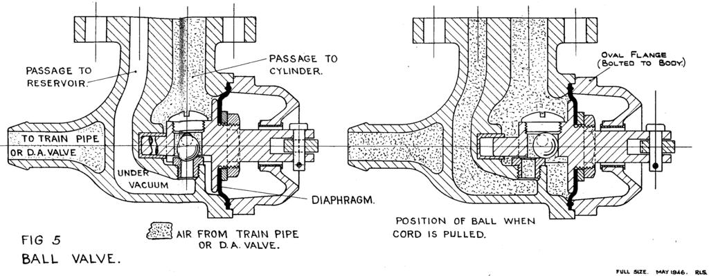
11 6 The piston rod is fastened to the piston head, and at its lower end it is connected by means of a pin to the lever mechanism which operates the brake blocks. In passing through the cylinder casing, the rod is surrounded by a rubber packing gland, the purpose of which is to prevent air entering the cylinder at this point, whilst at the same time permitting the piston rod to move in and out of the cylinder. The diagram, Figure 4, shows the piston in the "Brake on" position, and it should be noted that when the "Brake off" position is reached, the measurement from the packing gland to the boss end of the piston rod is 82". Occasionall y the older types of vehicle may be found to be fitted with a diaphragm type of cylinder. This type differs from the "rolling ring" type in that a rubber diaphragm is used instead of a rolling ring to seal off one side from the other. The principle of operation, however, is not altered. Ball valves. Fitted to the bottom of each cylinder and connecting the cylinder to the train pipe by means of an iron branch pipe and a small flexible hose, is a ball valve of the type shown in Figure 5. This valve is one of the most important fittings in the whole of the equipment, as its purpose is to control the passage of air to and from the reservoir portion of the brake cylinder. The passages in the valve body are so arranged that the underside of the cylinder is always in communication with the train pipe, whilst the reservoir portion of the cylinder is open to the train pipe only when the ball is unseated. So long as the ball is pressed on to its seat, therefore, the reservoir portion of the cylinder is isolated from the train pipe. Reference to Figure 4 will show that when air is withdrawn from the train pipe by the engine ejector, any air in the reservoir portion of the cylinder will flow past the ball into the train pipe until an equal vacuum exists on each side of the piston. The ball will remain unseated so long as this equality of vacuum exists, but as soon as air is again admitted to the train pipe it will enter the ball chamber and press the valve firmly on to its seat, thereby sealing off the reservoir portion of the cylinder and maintaining the vacuum which exists there. 7 The automatic action of the ball valve continues in this way so long as the brake equipment is under vacuum operation, but circumstances arise in which it is necessary to have a hand-operated means of equalising the conditions on each side of the brake piston. For instance, when a train is detached from an engine, the vacuum in the train pipe is completely destroyed, but by the action of all the ball valves in the train the vacuum in the reservoir portions of the brake cylinder is maintained, and so long as this vacuum remains the brake will remain "on" throughout the train. Embodied in the ball valve casting, therefore, is a sliding cage in which the ball is contained, and the outer end of this cage is connected to a cross lever. The action of pulling this lever pulls the cage outward, and this in turn pulls the ball off its seat. Air then flows into the reservoir portion of the cylinder until conditions are again equal on both sides of the piston, and the piston falls under its own weight to the bottom of the cylinder and the brake is released. In order that this release action may be carried out from the side of the coach, a wire or cord is taken from each side of the coach to one end of the cross lever, and to ensure that the cage returns to its normal position when vacuum operation is resumed, a diaphragm is connected to the cage. This diaphragm forms an air-tight gland where the cage spindle passes through the body of the ball valve, and as it is open to the atmosphere on the outside, any withdrawal of air from the ball valve interior causes the atmospheric pressure on the outside of the diaphragm to move the diaphragm inwards, thus returning the cage to its normal position. Direct admission valves. From time to time devices have been patented for accelerating the speed with which vacuum is destroyed, thereby reducing the time lag in the brake application between the front and the rear of long trains. The valve adopted for this purpose by the L.M.S.R. is the Direct Admission Valve, which is shown diagrammatically in Figure 4, and in detail in Figures 6 and 6a. The principle employed is that air entering the train pipe simply actuates the D.A. valve, and does not enter the brake cylinder, so that in effect each cylinder has an independent air supply and the operation of the brake gear as a whole is speeded up in consequence.
12 8 The manner in which the D.A. valve operates is as follows:- In the creation of a vacuum in the brake equipment, air is drawn from the cylinder, through passage C2, past non-return Valve "A" into the train pipe. At the same time air is extracted from chamber "B" past the flats "D" on the spindle until equal vacuum exists in chamber "B" and in the train pipe. Upon the reduction of the vacuum in the train pipe by the admission of air to the pipe, the diaphragm "E" is raised by reason of the higher degree of vacuum existing in chamber "B", and as the rising diaphragm carries with it the spindle, valve "F" is pushed open and admits air to the underside of the brake cylinder through passage "C1". When sufficient air has been admitted to reduce the vacuum in the cylinder, and, therefore, in passages "C1" and "C2", to the level of that in the train pipe, the diaphragm "E", being again in equilibrium, is restored to its original position by the spring "G", and valve "F" closes and prevents further flow of air to the cylinder. In the event of a D.A. valve requiring to be isolated, this can be achieved by reversing the cap "H" as shown in Figures 6 and 6a. Guard's brake application valves. To enable the guard of a train to apply the Automatic Vacuum Brake in case of emergency, a special guard's brake valve is provided in all passenger brake vans and brake compartments. The valve is not a graduable valve, in other words the lifting of the valve lever brings about a full application of the brake and no partial application of the brake is possible as is the case with the driver's brake valve on the engine. The type of valve shown in Figure 7 was used originally and contained automatic features. The majority of this type have, however, now been rendered non-automatic and are marked "N.N." to denote this. The vacuum chamber which is shown does not now serve any useful purpose. The type of valve shown in Figure 7a has now been adopted as the standard valve, and as the diagram shows it consists of a simple lever-operated flap valve. Passenger communication apparatus. Emergency communication apparatus is fitted to all passenger-carrying vehicles, and is as shown in Figures 8 and 8a. 9 ' he apparatus consists of a small diameter branch pipe connected at one end to the train pipe, and having at the other end a small flap valve. A horizontal shaft, suitably supported at each end, passes through the valve casing, and a cam is attached to the shaft in such a manner that a partial rotation of the shaft causes the cam to lift the flap valve into its "open" position. A continuous chain passes through the full length of the coach, and a small portion of this chain is made accessible in each compartment, and as the end of the chain is connected to the cross shaft previously mentioned, the action of pulling the chain at any point causes rotation of the cross shaft and so operates the flap valve. The valve is so designed that the amount of air admitted to the train pipe by the opening of the valve is sufficient to cause only a gradual application of the brake, and this, together with the resultant drop in the vacuum registered by the engine and brake compartment vacuum gauges is an indication to the driver and guard that something is amiss which calls for the train to be stopped. In order to give a clear indication of the vehicle in which the chain has been pulled, the cross shaft which operates the valve is provided with a disc at each end. Normally, these discs lie in the horizontal position, but when the shaft is operated it turns through an angle of 90, and the discs accordingly assume a vertical position and enable the affected coach to be found easily. Vacuum gauges. All passenger brake vans and brake compartments are fitted with a vacuum gauge in order that a guard may see at all times that the degree of vacuum called for under the Company's regulations has been created and is maintained. Many of these gauges are of the Duplex type, that is, they have the dual function of recording the degree of vacuum in the reservoir side as well as that in the train pipe. It should be noted, however, that the needle marked "Reservoir" only indicates the vacuum existing in the reservoir side of the cylinder to which it is connected; it does not indicate the conditions in the reservoirs of the other cylinders in the train. A single needle type of gauge only records the degree of vacuum existing in the main train pipe.
13 10 Brake block operating gear. Figure 9 shows the general arrangement of the brake rigging on a modern 4-wheeled bogie, and although the diagram shows one bogie only, the rigging on the bogie at the other end of the coach is identical. The power obtainable from the brake cylinder is transmitted through the rocking shaft to the main pull rod, and this main pull rod is in turn connected to a series of levers which operate the beams on which the brake blocks are mounted. The levers are arranged so that in addition to transmitting power from the brake cylinder, they equalise the power applied to the brake blocks so that each block is applied to the wheel with equal force. Adjustment is provided in the link connecting the vertical levers by means of a series of holes which permit a graduated variation in the distance between the pins connecting the link to the vertical levers. In designing a railway coach it is the aim to allow sufficient braking power to brake the vehicle efficiently without giving too severe, or too gradual a retarding effect, and experience has shown that the most satisfactory arrangement is that which gives a brake power equal to 75 to 80 per cent. of the weight of the vehicle. Thus, in a coach weighing 30 tons, a brake power of 22 to 24 tons is provided for in designing the brake equipment. It was shown on page 2 that with a partial vacuum equal to 20" of mercury in the reservoir side of a brake cylinder, a pressure of 10 lb. per sq. inch is obtained on the side of the piston which is under atmospheric pressure. With an 18" diameter cylinder, therefore, the total pressure on the piston under these conditions will be:- 10 lbs. x total area of piston which equals 10 lbs. x sq. in. = 2,545 lbs. pressure on piston. By making the rocking shaft, to which the piston is coupled, so that a 2 to 1 leverage is obtained, this figure of 2,545 is doubled at the short arm of the rocking shaft, and by coupling the main pull rod to the short arm, a pull of 2 x 2,545 lbs. = 5,090 lbs. is obtained in the main pull rod. The system of levers between the main pull rod and the brake block beams then multiplies this force even further, until the total of the forces on the sixteen brake blocks is equal to 22 to 24 tons 11 The operation of the Automatic Vacuum Brake. Before a train commences its journey, the operation of the vacuum equipment must be tested, and whilst the following describes L.M.S.R. practice and may differ slightly in detail from the practice of other Companies, the general principles are identical. First, the engine is tested as an independent unit before it leaves the shed, and it is the duty of the driver to ensure that the vacuum equipment is in good working order. Subsequently, when the engine has been coupled to a train, the train pipe flexible hoses between vehicles coupled, and the flexible hose at the end of the last vehicle correctly seated on the stopper, the driver admits steam to the engine ejector and exhaustion of the vacuum equipment throughout the train commences. This action releases the brake throughout the train, and the guard must observe the vacuum gauge in the brake compartment until a reading of at least 17" is noted. He must then lift the handle of the emergency brake valve, thus applying the brake throughout the train, and after returning the valve to the closed position again must watch the vacuum gauge whilst vacuum is being restored until the reading is again not less than 17". This test must also be carried out whenever a vehicle is detached from a train, or when an additional vehicle is attached to a train, and in fact it should be the practice to carry out the test whenever train pipe flexible hoses are disconnected for any purpose. The test completed satisfactorily, the train is ready to proceed, and the requisite vacuum having been created, as described above, to release the brake, the application of the brake is now normally under the control of the engine driver.
14 Use of clearance gauges. Before the clearance between brake blocks and wheels can be checked, the brake must be fully released, i.e. the brake piston must be in its lowest position, and where equalising links are fitted, these should be close up to the stops. Steps must, of course, be taken to prevent vehicles moving in either direction when the brake has been released 13 Part H. EXAMINATION AND TESTING OF A.V.B. EQUIPMENT. Examination and adjustment. The trouble-free operation of A.V.B. equipment on coaching and freight stock depends upon careful examination and maintenance of the equipment. It is essential, therefore, that trains or loose vehicles which are placed in carriage sidings and are left under the control of the Automatic Vacuum Brake should be examined upon arrival, and particular attention directed to the following points:- Brake block adjustment. The state of adjustment of the brake blocks must allow the maximum stroke of the brake piston to be available. The efficiency of the gear is dependent upon its being adjusted as closely as possible to the limit allowed, as otherwise much of the power available in the brake cylinder is lost before the brake blocks come into contact with the wheels. Any brake blocks which have worn down to scrapping size must, of course, be replaced without delay.
15 14 4-wheeled bogie. The brake block adjustment on 4-wheeled bogies should allow free movement of the I" gauge between the brake blocks and wheels. In the case of vehicles having the long and short arm type of triangular brake beam, the gauge should be inserted on the "long" arm side; on other types it is immaterial on which side the gauge is used. 6-wheeled bogie. The adjustment of brake blocks on a 6-wheeled bogie requires the use of two gauges which must be inserted between the brake blocks and tyres of two wheels. Care must be taken in the examination or adjustment of brake gear to ensure that the gear as a whole works freely, that all portions of the gear are properly secured and that the legs of all split cotters are well opened. Hand brakes. The hand brake on all vehicles so fitted must be examined and tried as vehicles come to hand at carriage depots or freight sidings, to ensure that the brake is properly workable. If found to be in need of adjustment, the adjustment must be carried out before the vehicle is again allowed into traffic. Vacuum equipment. In the examination of vehicles standing under control of the Automatic Vacuum Brake, attention must be directed to the air-tightness of the equipment and any tendency to "leak-off" noted. Particular attention should be paid to piston rod glands and D.A. valves. When opportunity permits, brake piston rods which are not protected by flexible stockings should be cleaned with dry spun yarn. Under no circumstances, however, must any abrasive cleaning compound be used on the spun yarn. Flexible hoses and branch pipes should be examined for such defects as worn hoses, defective or damaged couplings or defective joint washers. The clips securing flexible hoses to couplings and train pipes should be examined and left secure and in contact with the hose throughout the circumference. Any clips having a damaged tongue must be changed, and the coupling pins and chains must be left in good condition. 15 Passenger communication apparatus. At monthly intervals the passenger communication apparatus must be operated to ensure that the apparatus works freely, and all parts must be left in a clean condition and in good working order. Any worn, hardened, or otherwise defective valve seating washers must be changed and defective chains renewed. Guards' emergency application valves. Guards' emergency valves must be tried to ensure that they operate freely and that the valve seating washer is in good condition. Vacuum gauges. Vacuum gauges must be examined for such visible defects as loose connections, bent needles, broken glasses or bent or defaced dials, and when tested under vacuum, care must be taken to see they are registering correctly. Brake cylinder release valves. Release valves having defective cords or wires, or showing any sign of diaphragms leaking, should be noted and attention given. Adverse weather conditions-frost. Whenever severe frost is anticipated, steps must be taken to prevent the brake blocks of vehicles stabled in exposed positions from becoming frozen to the wheels. Brakes must, therefore, be released by operating the release valves, but care must be taken to ensure that the vehicles are properly secured and are unable to move in any direction which might result in their fouling other roads. Testing and irregularities. Every effort should be made to test the brake equipment on vehicles before they are brought into use in order that irregularities in the operation of the equipment or leakages may be located and rectified.
16 16 Test apparatus. The standard apparatus for testing A.V.B. equipment consists of:- (a) Leak discs, for testing the efficiency of the engine ejector. These are circular discs having either a -&" or v" diameter hole in the centre, and their overall diameter is such that they will cover the open end of the flexible hose coupling which is shown in Figure 3. (b) Isolating cocks for isolating portions of the A.V.B. equipment and recording the degree of vacuum existing. These cocks have a standard flexible hose coupling of the type shown in Figure 3 at either end, and can, therefore, be used to connect the flexible hoses between an engine and train or between vehicles, or can be used in connection with a leak disc. As the cocks embody a vacuum gauge, they can be used:- (1) To test the ejector equipment on the engine. (2) To isolate the train pipe on a train after the engine has created a vacuum and to show what vacuum is maintained after isolation of the train pipe. (3) To test conditions on the engine and train when coupled together. Test cocks must be carefully handled to avoid damage to the gauges, and the cocks must be periodically tested in accordance with instructions against a master vacuum gauge or mercury column to ensure that they are in good working order and their gauges registering correctly. Irregularities-testing of equipment. The failure of an engine to create and maintain the regulation degree of vacuum throughout a train may be due to one or more of the following defects:- (1) Front flexible hose on engine or rear flexible hose on train not seated correctly on stopper. (2) Leakage in flexible hose couplings between vehicles. (3) Passenger communication valve or valves partly open. 17 (4) Leakage at brake cylinder piston rod gland packings. (5) Leakage at brake cylinder release valves, D.A. valves, guards' emergency valve, or joint washers. During examination of a train, steps must, whenever necessary, be taken to determine whether the vacuum gauge in the rear brake or brake compartment is registering correctly. It may occur, however, that the defect cannot be located during examination, and the action to be taken by the C. & W. examiner in these circumstances is as follows:- 1.-Engine equipment (failure to create the requisite amount of vacuum throughout a train). If the cause of the trouble cannot be located during examination of the train, the examiner must first ascertain that the boiler pressure is within 10 lbs. of the working pressure, and the actual pressure indicated by the boiler pressure gauge must be noted by the examiner and the driver. Accompanied by the fireman, the examiner must then make a leak disc test in the following manner:- (a) Engines fitted with combined large and small ejector. Uncouple the engine or tender flexible hose from the train and couple this hose to the isolating cock. Place a -&"leak discover the open end of the isolating cock and hold this in position. The driver must then create 20"-21" of vacuum with the large ejector and must maintain this degree of vacuum with the small ejector only. This must be recorded by the vacuum gauge attached to the isolating cock, and if no difficulty is experienced in maintaining 20'-21" of vacuum as stipulated, the engine is not at fault. (b) Engines fitted with a single ejector and a vacuum Pump. Proceed as in (a), but use a 4" leak disc. The driver must then create 20"-21" of vacuum with the ejector, and if this is recorded on the gauge attached to the isolating cock and can be maintained without difficulty, the engine is not at fault. No test of the vacuum pump is required, as this comes into operation only when the engine is running.
17 is If an isolating cock is not available the foregoing tests can be made using the leak discs only. In this case the discs should be applied direct to the coupling of the engine or tender flexible hose, and the degree of vacuum obtained should be observed from the vacuum gauge on the engine and noted by both the examiner and the driver. If the engine is unable to fulfil the conditions stipulated and is, therefore, at fault, the Station Master must take steps to have the fault remedied or to have another engine provided. If some time is likely to elapse before an engine is available, steps should be taken by the Station Master, during the waiting period, to have tests continued throughout the train by using any suitable engine which may be available, as cases have occurred where both engine and train have been at fault; such further tests should, whenever practicable, be made from the leading end of the train. 2.-Train equipment. Having ascertained that the engine equipment is satisfactory and the train equipment at fault, the examiner must proceed to test the train in the following manner:- Couple the engine or tender flexible hose to the train flexible hose with the isolating cock inserted between the two hoses. Use the engine ejector to create a vacuum of 20"-21", as indicated by the isolating cock gauge, and then turn the cock so that the train is isolated from the engine. If the gauge needle falls rapidly, indicating a leakage in the train equipment, repeat the test process between vehicles, in groups of three or four vehicles, until the defect is located. Irregularities-remedial action. Flexible hoses.-defective flexible hoses, whatever the defect, should be replaced, and care must be taken in fitting the replacement hose to see that the clip is in contact with the hose throughout its circumference and the tongue not in any way distorted. D.A. valves. D.A. valves found to be defective should be blanked off by removing the top wing nut and cap, placing an old repair card slightly smeared with oil on top of the valve, and replacing the cap in the reverse position, finally screwing down the wing nut securely. 19 $rake cylinders. Should a "rolling ring" type of brake cylinder be found to be defective, the flexible branch pipe from the ball valve to the D.A. valve should be disconnected at the ball valve and the pipe plugged on the train pipe side with the special type of plug which is provided for the purpose. The defective cylinder should then be equalised by pulling the release wire to the ball valve and holding this until all vacuum existing in the cylinder has been destroyed. Where a brake piston sticks in the cylinder it is not desirable to uncouple the piston rod, and the action outlined above will generally suffice. Should the piston be held fast with the brake hard on, however, and cannot be moved towards the "off" position, the piston must be disconnected from the rocking shaft by removing the connecting pin. When such action is taken, the cylinder must be prevented from turning over by securing it suitably through the piston rod pin-hole. The long arm of the rocking shaft must also be secured so that it cannot fall downward and foul the permanent way. Steps must also be taken to see that the brake blocks affected are left clear of the wheels, and that the wheels have not sustained any damage through prolonged braking or skidding which would result in the vehicle being unfit for traffic. In the event of a diaphragm type of cylinder being found to he defective, it should be isolated by disconnecting the branch pipe and inserting a suitable plug to render the train pipe air-tight. It should be understood that in all the foregoing cases, or whenever any action is taken to temporarily isolate or render ineffective any part of the vacuum equipment of a vehicle, a "for repair" card must be attached to each side of the vehicle concerned before it is allowed forward, and a comprehensive repair must be made at the earliest opportunity. Excessive vacuum in reservoirs. It may occur that upon an engine being coupled to a train, the creation of 20"-21" of vacuum does not fully release the brake. This is due to the fact that the engine previously attached to the train created more than 21" of vacuum, and the reservoir portions of all the cylinders

18 20 are therefore left with more than the stipulated degree of vacuum, and do not balance with the 20"-21" created by the second engine when the latter is connected to the train pipe. In these circumstances, equilibrium must be restored in all the cylinders of the train by operating each release valve in succession, and when this has been done, recreating vacuum throughout the equipment in the normal way. Safety precautions. The attention of all concerned is directed to the necessity of complying with the Company's regulations for the protection of staff working on carriages and wagons, E.R.O and 10445, whenever called upon to effect any repair or adjustment, etc., to the Automatic Vacuum or Hand Brake on either coaching or freight stock.
19
20
21
22
23
24
25
26
27
28
29
Train Examination (Braking System) Addendum. Lesson Plan and WorkBook
 Addendum. Lesson Plan and WorkBook") Train Examination (Braking System) Addendum Lesson Plan and WorkBook (Generic Version) Version 1 June, 2011 IMPORTANT NOTICE This booklet is one of a series of generic training and assessment templates
Train Examination (Braking System) Addendum Lesson Plan and WorkBook (Generic Version) Version 1 June, 2011 IMPORTANT NOTICE This booklet is one of a series of generic training and assessment templates
JACKALL HYDRAULIC SYSTEM
 JACKALL HYDRAULIC SYSTEM FIG. 1. Layout of a typical installation. Servicing Instructions for Red Jackall. The Red Jackall hydraulic system requires no attention other than a periodical examination of
Train Examination (Braking System) Addendum
 Addendum") Train Examination (Braking System) Addendum Mentor s Q&A (Generic Version) Version 1 June, 2011 IMPORTANT NOTICE This booklet is one of a series of generic training and assessment templates developed by
Train Examination (Braking System) Addendum Mentor s Q&A (Generic Version) Version 1 June, 2011 IMPORTANT NOTICE This booklet is one of a series of generic training and assessment templates developed by
SWINDON ENGINEERING SOCIETY. BRAKES FOR MODERN EXPRESS PASSENGER TRAINS,
 [No 127.] G.W.R. Mechanics Institution. SWINDON ENGINEERING SOCIETY. TRANSACTIONS, 1920-21 ORDINARY MEETING February 22nd, 1921. Chairman Mr. F. W. Hawksworth. BRAKES FOR MODERN EXPRESS PASSENGER TRAINS,
HE Stewart Vacuum Gasoline System employs a small tank, installed under the hood. This tank is connected by brass tubing to the intake manifold, also
 T HE Stewart Vacuum Gasoline System employs a small tank, installed under the hood. This tank is connected by brass tubing to the intake manifold, also to gasoline supply tank, and to carburetor. Every
E17M ROLLING STOCK BRAKES
 E17M ROLLING STOCK BRAKES PURPOSE AND SCOPE The purpose of this Procedure is to advise Laing O Rourke personnel of the braking standards to be applied and to ensure those people involved in maintaining
Railway Technical Web Pages
 Railway Technical Web Pages Archive Page Vehicle Suspension Systems Introduction Almost all railway vehicles use bogies (trucks in US parlance) to carry and guide the body along the track. Bogie suspension
SLtr ge. r iiisinto operation ' wm. The extent of the movement of the lever C, is controlled CHAPTER VII.
 SLtr ge r iiisinto operation ' wm «* PREECE'S THREE-WIRE SYSTEM. 6? CHAPTER VII. PREECE'S THREE-WIRE SYSTEM. no. MR. PREECE'S three-wire system is a permanent current system only as regards the rendering
APPENDIX I. B Y. Member.
 PAMPHLE T NO. 18. APPENDIX I. B Y Member. Read Wednesday, February 28th, 1894. HE subject of Railway Brakes is a most important and interesting one to everyone connected in any way with railways. When
Carburetor Instructions
 Carburetor Instructions for HUDSON SUPER SIX ESSEX SIX CYLINDER Hudson Motor Car Co. DETROIT, U.S.A. Carburetor The carburetor is a device for metering correct amounts of fuel and air for the various
Valves. External Valves, Gages and Fittings. Bulletin No What options are available when stainless steel is not suitable for external parts.
 External Valves, Gages and Fittings Bulletin No. 218 What options are available when stainless steel is not suitable for external parts. Unless otherwise specified, the external valves, gages, fittings
AAR Manual of Standards and Recommended Practices Brakes and Brake Equipment CODE OF AIR BRAKE SYSTEM TESTS FOR FREIGHT EQUIPMENT SINGLE CAR TEST
 S-486 AAR Manual of Standards and Recommended Practices CODE OF AIR BRAKE SYSTEM TESTS FOR FREIGHT EQUIPMENT SINGLE CAR TEST Standard S-486 Adopted: 1991; Last Revised: 2018 TABLE OF CONTENTS Paragraph
1 THE WOLVERTON SYSTEM OF TRAIN LIGHTING.
 1 THE WOLVERTON SYSTEM OF TRAIN LIGHTING. The Wolverton equipment is a single battery system utilising a plain shunt wound dynamo. The dynamo is controlled by an automatic field regulator which senses
GUIDELINES ON ELECTRICAL SAFETY AT WORKPLACES
 MINISTRY OF LABOUR, INDUSTRIAL RELATIONS AND EMPLOYMENT GUIDELINES ON ELECTRICAL SAFETY AT WORKPLACES Occupational Safety & Health Inspectorate These guidelines should be used with approved standards:
COPYRIGHT NOTICE This PDF file has been created from the original book with permission of BRB (Residuary) Ltd, who retains copyright in the original
 Ltd, who retains copyright in the original") COPYRIGHT NOTICE This PDF file has been created from the original book with permission of BRB Residuary) Ltd, who retains copyright in the original document. The scanned images of this book were provided
COPYRIGHT NOTICE This PDF file has been created from the original book with permission of BRB Residuary) Ltd, who retains copyright in the original document. The scanned images of this book were provided
SECTION D REAR SUSPENSION. Section Description Page D.1. REMOVING AND REFITTING A REAR SUSPENSION UNIT 5
 SECTION D REAR SUSPENSION Section Description Page D.1. REMOVING AND REFITTING A REAR SUSPENSION UNIT 5 D.2. REMOVING AND REFITTING THE COMPONENTS OF THE REAR SUSPENSION 8 D.3. CHECKING AND OVERHAULING
TILLOTSON LTD., CLASH INDUSTRIAL ESTATE, TRALEE, CO. KERRY, IRELAND PHONE: FAX:
 TILLOTSON LTD., CLASH INDUSTRIAL ESTATE, TRALEE, CO. KERRY, IRELAND PHONE: +353 66 7121911 FAX: +353 66 7124503 e-mail: sales@tillotson.ie SERIES SERVICE MANUAL INTRODUCTION The gasoline engine industry
walton TEMPERATURE CONTROL SYSTEMS Pneumatically Operated (Rotary)
") walton TEMPERATURE CONTROL SYSTEMS Pneumatically Operated (Rotary) WALTON ENGINEERING CO. LTD. 61 London Road St Albans Hertfordshire AL1 1LJ England Telephone +44 (0)1727 855616 Fax +44 (0)1727 841145
walton TEMPERATURE CONTROL SYSTEMS Pneumatically Operated (Rotary) WALTON ENGINEERING CO. LTD. 61 London Road St Albans Hertfordshire AL1 1LJ England Telephone +44 (0)1727 855616 Fax +44 (0)1727 841145
Status: DRAFT Version: 01 Ref.: A I/ Original: EN Date:
 Page 1 of 34 APTU Uniform Rules (Appendix F to COTIF 1999) Uniform Technical Prescriptions (UTP) applicable to Rolling Stock, subsystem FREIGHT WAGONS - (UTP WAG) - ANNEX I BRAKING INTERFACES OF BRAKING
Fuel and exhaust systems 4A 21
 Fuel and exhaust systems 4A 21 15.40 Unscrew the union nuts and disconnect the fuel feed and return hoses from the manifold 41 Disconnect the injector wiring harness connector and the vacuum hose from
Principals of Operation... 1 Rotary Vane Priming Pump VPE and VPES... 2 Rotary Vane Priming Pump VPO and VPOS Priming Valve...
 Priming Systems Installation Priming Systems Operation & Maintenance Form No. F 1031 Section 2312 Issue Date 10/07/94 Rev. Date 02/27/06 Table of Contents Illustrations Principals of Operation...........................
9 Locomotive Compensation
 Part 3 Section 9 Locomotive Compensation August 2008 9 Locomotive Compensation Introduction Traditionally, model locomotives have been built with a rigid chassis. Some builders looking for more realism
Hydrostatic And Mechanical Lubricators
 FRONZ / ONTRACK APPROVED CODE OF PRACTISE FOR HERITAGE NETWORK OPERATORS Mechanical Supplementary Code B3.3.2.03 Hydrostatic And Mechanical Lubricators Issue Prepared (P), Approved by Effective Date Reviewed
Mechanical Equipment - Course 230.1
 Mechanical Equipment - Course 230.1 BELT DRIVES A conunon method of transmitting power is a combination of belts and pulleys, There are many types of belts and pulleys used for the transmission of power
AUTOMATIC CLUTCH Models
 AUTOMATIC CLUTCH 1940 Models Source of this material is from 1940 Series, Issue 4, January 1940 Hudson Service Magazine AUTOMATIC CLUTCH 1940 MODELS The automatic clutch installation and adjustment procedure
Self-Adjusting Clutch (SAC) Technology Special tools / User instructions
 Technology Special tools / User instructions") Self-Adjusting Clutch (SAC) Technology Special tools / User instructions The content of this brochure shall not be legally binding and is for information purposes only. To the extent legally permissible,
Self-Adjusting Clutch (SAC) Technology Special tools / User instructions The content of this brochure shall not be legally binding and is for information purposes only. To the extent legally permissible,
Chapter 4 Part D: Exhaust and emission control systems
 4D 1 Chapter 4 Part D: Exhaust and emission control systems Contents Air inlet heating system components - removal and refitting...... 4 Catalytic converter - general information and precautions........
ESCONDIDO FIRE DEPT TRAINING MANUAL Section DRIVER OPERATOR Page 1 of 13 Pumps and Accessory Equipment Revised
 DRIVER OPERATOR Page 1 of 13 PUMPS AND ACCESSORY EQUIPMENT Pumps are designed for many different purposes. In order to understand the proper application and operation of a pump in a given situation, firefighters
The Knowledge Bank at The Ohio State University. Ohio State Engineer. Electrolysis in Underground Structures
 The Knowledge Bank at The Ohio State University Ohio State Engineer Title: Creators: Issue Date: Publisher: Electrolysis in Underground Structures Rei, P. F. Pepper, H. C. Hoover, C. H. Frankenberg, R.
Westingh'ouse Steam Turbines-I. B (Rev. 3) GOVERNOR, GOVERNING VALVE
 GOVERNOR, GOVERNING VALVE") Supersedes l. B. 697 (Rev. 2) Westingh'ouse Steam Turbines-I. B. 697 (Rev. 3) GOVERNOR, GOVERNING VALVE AND OIL PUMP This governor mechanism comprises a vertical shaft centrifugal weight governor a gear
Supersedes l. B. 697 (Rev. 2) Westingh'ouse Steam Turbines-I. B. 697 (Rev. 3) GOVERNOR, GOVERNING VALVE AND OIL PUMP This governor mechanism comprises a vertical shaft centrifugal weight governor a gear
Centralised Traffic Control System - Rules 1 to 17
 Centralised Traffic Control System - Rules 1 to 17 Applicability VIC Publication Requirement External Only Document Status Issue/Revision # Effective from 2 13 May 2012 0 04 October 2015 Australian Rail
HA Thickness Gauge IS:2386 (part 1)- 1963
- 1963") AGGREGATE TESTING HA50.05 Mechanical Rotating Sample Divider (Motorised) IS : 1607-1960 For obtaining representative sample for sieve analysis. It is suitable for dry sands, fine powders, ores, refractory
AGGREGATE TESTING HA50.05 Mechanical Rotating Sample Divider (Motorised) IS : 1607-1960 For obtaining representative sample for sieve analysis. It is suitable for dry sands, fine powders, ores, refractory
SECTION 11 INTERMODAL EQUIPMENT
 SECTION 11 INTERMODAL EQUIPMENT ROA MANUAL SCHEDULE OF AMENDMENTS SECTION 11 AMENDMENT NUMBER PAGES AMENDED AMENDMENT SUMMARY DATE ISSUED TABLE OF CONTENTS Section Description Page No. 11.1 SCOPE... 11-1
The Life of a Lifter, Part 2
 Basics Series: The Life of a Lifter, Part 2 -Greg McConiga Last time we looked at some complicated dynamics and compared flats to rollers. Now for the hands-on. 6 FEATURE This off-the-shelf hydraulic lifter
INSTALLATION, OPERATION AND MAINTENANCE INSTRUCTIONS
 INSTALLATION, OPERATION AND MAINTENANCE INSTRUCTIONS Contents Section 1. General Observations... 2 2. Operation... 4 3. Control During Operation... 5 4. Trouble Shooting... 6 5. Maintenance... 7 Please
PARTS CATALOGUE / TECHNICAL GUIDE
 PARTS CATALOGUE / TECHNICAL GUIDE PARTS CATALOGUE / TECHNICAL GUIDE (p. 1 21) CATÁLOGO DE PARTES / GUÍA TÉCNICA (p. 23 43) [SPECIFICATIONS] Item Movement Cal. No. 5J22A (x 1.0) Movement size Outside diameter
The distributor valve
 The distributor valve Understanding the operation of a pneumatic brake, and in particular of the operating principles of the pneumatic control, relies on understanding the global operation of the main
Heat Engines Lab 12 SAFETY
 HB 1-05-09 Heat Engines 1 Lab 12 1 i Heat Engines Lab 12 Equipment SWS, 600 ml pyrex beaker with handle for ice water, 350 ml pyrex beaker with handle for boiling water, 11x14x3 in tray, pressure sensor,
SHAFT ALIGNMENT FORWARD
 Service Application Manual SAM Chapter 630-76 Section 24 SHAFT ALIGNMENT FORWARD One of the basic problems of any installation is aligning couplings or shafts. Therefore, this section will endeavor to
jegs.com. Installation Instructions for Ton Aluminum Floor Jack
 Installation Instructions for 80077 3-Ton Aluminum Floor Jack Contents: Specifications Warning Information Setup and Operating Instructions Preventive Maintenance and Troubleshooting Hydraulic Maintenance
BURQUIP INTERNATIONAL (PTY) LTD
 LTD") Chapter 6 Transmission The transmission system comprises all of the components that transfer the force and movement from the Braked Coupler to the inertia brakes in the axles. Fit the axles to the trailers
Chapter 6 Transmission The transmission system comprises all of the components that transfer the force and movement from the Braked Coupler to the inertia brakes in the axles. Fit the axles to the trailers
Instructor Training Manual. Chapter 6 HYDRAULICS & PNEUMATICS
 Instructor Training Manual Chapter 6 HYDRAULICS & PNEUMATICS Learning Objectives 1. The purpose of this chapter is to provide a basic introduction to the principles of hydraulics & pneumatics and their
BRISTOL SOCIETY OF MODEL & EXPERIMENTAL ENGINEERS ASHTON COURT ESTATE MINIATURE RAILWAY
 BRISTOL SOCIETY OF MODEL & EXPERIMENTAL ENGINEERS ASHTON COURT ESTATE MINIATURE RAILWAY Miniature Locomotive Driver Training and Authorisation Issue 3 March 2016 Before commencing training, please ensure
STEERING SYSTEM Introduction
 STEERING SYSTEM Introduction The steering makes it possible to change direction. The steering must be reliable and safe; there must not be too much play in the steering. It must be possible to steer accurately.
500R MIXER SYPHON TYPE WATER TANK WORKSHOP MANUAL
 500R MIXER SYPHON TYPE WATER TANK WORKSHOP MANUAL WINGET LIMITED PO BOX 4 EDGEFOLD INDUSTRIAL ESTATE PLODDER LANE BOLTON LANCS BL4 OLS TEL: ++ 44 (0) 04 854650 FAX: ++ 44 (0) 04 854663 service@winget.co.uk
AN EXPLANATION OF CIRCUITS CARTER YH HORIZONTAL CLIMATIC CONTROL CARBURETER
 AN EXPLANATION OF CIRCUITS CARTER YH HORIZONTAL CLIMATIC CONTROL CARBURETER The Carter Model YH carbureter may be compared with a Carter YF downdraft carbureter with the circuits rearranged to operate
Train Brakes. For best viewing, set the size to show one whole page only, and use the Page Down button to move through the slides.
 Issue 1 March 2012 Slide 1 of 324 Train Brakes These are the notes of a presentation made by Dominic Wells specially for the locomotive crews of the Ffestiniog and Welsh Highland Railways in 2011. For
NEOTECHA NTB-NTC BALL VALVES INSTALLATION AND MAINTENANCE INSTRUCTIONS
 Before installation these instructions must be fully read and understood 2 SAFETY Please also read through these notes carefully. 2.1 General potential danger due to: a. Failure to observe the instructions
SECTION 5 STANDARD TRAIN EXAMINATION PROCEDURES
 SECTION 5 STANDARD TRAIN EXAMINATION PROCEDURES ROA MANUAL SCHEDULE OF AMENDMENTS SECTION 5 AMENDMENT NUMBER PAGES AMENDED AMENDMENT SUMMARY DATE ISSUED TABLE OF CONTENTS Section Description Page No. 5.1
Air brakes Introduction
 Slide 206 of 324 Air brakes Introduction Slide 207 of 324 Air brakes Discussion As the Ffestiniog and Welsh Highland Railway (F&WHR) uses vacuum brakes, you may wonder why a section on air brakes is included
Pump Operating and Maintenance Manual - Models
 Pump Operating and Maintenance Manual - Models 78-00111 - 78-0057 Thank you for purchasing the SDI Diaphragm Pump manufactured by Comet Pump. Comet produces quality products which are safe, efficient and
Sales : Mobile : The Zenith 24 T-2 carburettor
 The Zenith 24 T-2 carburettor is an up draught carburettor, developed principally for use on your Ferguson TEA20 (Vaaljapie) tractor. It can be supplied in several versions, the main variations being the
SECTION 7 FREIGHT VEHICLE BRAKES AND BRAKE EQUIPMENT
 SECTION 7 FREIGHT VEHICLE BRAKES AND BRAKE EQUIPMENT ROA MANUAL SCHEDULE OF AMENDMENTS SECTION 7 AMENDMENT NUMBER PAGES AMENDED AMENDMENT SUMMARY DATE ISSUED CONTENTS Section Description Page 7.1 SCOPE
20 TONNE HYDRAULIC PRESS MODEL NO: CSA20FBT
 20 TONNE HYDRAULIC PRESS MODEL NO: CSA20FBT PART NO: 7614058 OPERATION & MAINTENANCE INSTRUCTIONS WARNING: Read these instructions before using the press GC0516 INTRODUCTION Thank you for purchasing this
SECTION 24 FREIGHT VEHICLE FIELD INSPECTION LIMITS FOR IN-SERVICE USE
 SECTION 24 FREIGHT VEHICLE FIELD INSPECTION LIMITS FOR IN-SERVICE USE ROA MANUAL SCHEDULE OF AMENDMENTS SECTION 24 AMENDMENT NUMBER PAGES AMENDED AMENDMENT SUMMARY DATE ISSUED Portions of this Section
Pre-Trip or Interim Inspection of Heritage Steam Locomotives
 Page 1 of 5 Pre-Trip or Interim Inspection of Heritage Steam Locomotives Date of Inspection / / Vehicle ID Operator Inspected at This Vehicle is fit to operate run on the National Rail System with the
Vacuum Bleeder Kit. Product:
 Vacuum Bleeder Kit Product: 119-020 Warning! These pumps are not approved for use with combustible materials such as gasoline, kerosene, or diesel fuel. Serious injury or damage may occur if pump is used
Brake Systems. Introduction
 Brake Systems Figure 1. A Typical Brake System Introduction The brake system (Figure 1) is designed to slow and halt the motion of a vehicle. To do that, various components within a hydraulic brake system
Medium and high pressure pumps
 Screw pumps Medium and high pressure pumps Installation and Start-up Instruction This instruction is valid for all standard high pressure pumps: E4, D4 and D6 Contents Page Pump identification 2 Installation
VB VALVES & AUTOMATION
 Introduction to Valve What are Valves? Valves are mechanical device that controls the flow and pressure within a system or process. They are essential components of a piping system that conveys liquids,
A Practical Guide to Free Energy Devices
 A Practical Guide to Free Energy Devices Part PatD20: Last updated: 26th September 2006 Author: Patrick J. Kelly This patent covers a device which is claimed to have a greater output power than the input
SERVICE MANUAL. Common Rail System for HINO J08C/J05C Type Engine Operation. For DENSO Authorized ECD Service Dealer Only
 For DENSO Authorized ECD Service Dealer Only Diesel Injection Pump No. E-03-03 SERVICE MANUAL Common Rail System for HINO J08C/J05C Type Engine Operation June, 2003-1 00400024 GENERAL The ECD-U2 was designed
TYPE 200 IOM - VACUUM BREAKER
 TYPE 200 IOM - VACUUM BREAKER INSTALLATION, OPERATION & MAINTENANCE INSTRUCTIONS TYPE 200 VACUUM BREAKER TABLE OF CONTENTS Overview... COVER General Information... COVER Installation... 4 Operation...
HPB Hydraulic Power Braking System
 HPB Hydraulic Power Braking System 4 th Edition This publication is not subject to any update service. New versions are available in INFORM at www.wabco-auto.com Copyright WABCO 2007 Vehicle Control Systems
Heavy Duty Miniature Quick-Change Applicator (Side-Feed Type) with Mechanical or Air Feed Systems
 with Mechanical or Air Feed Systems") Heavy Duty Miniature Quick-Change Applicator (Side-Feed Type) with Mechanical or Air Feed Systems Instruction Sheet 408-8040 30 NOV 17 Rev H Ram Assembly Ram Post Locking Screw Stock Drag Drag Release
Heavy Duty Miniature Quick-Change Applicator (Side-Feed Type) with Mechanical or Air Feed Systems Instruction Sheet 408-8040 30 NOV 17 Rev H Ram Assembly Ram Post Locking Screw Stock Drag Drag Release
ENGINEDRIVER 1ST-GRADE AIR BRAKE EXAMINATION TYPICAL QUESTIONS & ANSWERS
 ENGINEDRIVER 1ST-GRADE AIR BRAKE EXAMINATION TYPICAL QUESTIONS & ANSWERS 1. What are the two most important new features of the 26C 1 Automatic brake valve? i. Self-lapping: whereby the Regulating portion
Back pressure safety valves
 1/12 Back pressure safety valves 1. Introduction 2. Safety valve in the installation 3. Influence of back pressure on functioning behaviour 4. Limits of admissible back pressure (without metal bellow)
Toyota Landcruiser Rear Brake Upgrade Package
 May 2007 Toyota Landcruiser Rear Brake Upgrade Package 9 Nevada Ct Hoppers Crossing Vic 3029 Ph 03 97486950 Fax 03 97485965 Email hopstop@hoppers.com.au Web www.hoppers.com.au 2 THE INFORMATION CONTAINED
IMPORTANT INSTRUCTIONS FOR OPERATION & MAINTENANCE OF
 IMPORTANT INSTRUCTIONS FOR OPERATION & MAINTENANCE OF CONVEYORS EASIKIT 300 EASIKIT 450 EASIKIT 600, 900, 1200 & 1500 The manufacturer does not accept responsibility for any loss, damage to other equipment,
Chapter 5 Part B: Ignition system - transistorised type
 5B 1 Chapter 5 Part B: Ignition system - transistorised type Contents Coil - testing........................................... 9 Distributor - overhaul..................................... 7 Distributor
SHOT BLAST CABINET MODEL No. CSB20B Part No OPERATING & MAINTENANCE INSTRUCTIONS
 SHOT BLAST CABINET MODEL No. CSB20B Part No. 7640110 1001 OPERATING & MAINTENANCE INSTRUCTIONS Item Description Part No. Item Description Part No. SPARE PARTS AND SERVICING Please contact your nearest
DESCRIPTION FUEL AND VACUUM PUMP REMOVE AND REPLACE FUEL PUMP-OVERHAUL 6B PONTIAC SHOP MANUAL. S. Install battery and connect cables.
 6B-74 1955 PONTIAC SHOP MANUAL DESCRIPTION FUEL AND VACUUM PUMP All models are equipped with a combination fueland double acting vacuum pump operated by an eccentric bolted to the front end of the engine
SL-6 & SL-6A. I UNION SWITCH & SIGNAL l[ml 645 Russell Street Batesburg, SC Service Manual Field and Shop Maintenance
 I UNION SWITCH & SIGNAL l[ml 645 Russell Street Batesburg, SC 29006 Service Manual 3011 SL-6 & SL-6A Outlying Switch Lock Field and Shop Maintenance April, 1979 A-79-500-1496-3 1979, Union Switch & Signal
E17H RAIL WHEEL INSPECTION
 E17H RAIL WHEEL INSPECTION PURPOSE AND SCOPE This Procedure applies to all items of rolling stock purchased or acquired through hiring or other means by Laing O Rourke for the railway operations they will
2 TON CAPACITY PROFESSIONAL SERIES ALUMINUM JACK OWNER'S MANUAL SPECIFICATIONS
 80006 OWNER'S MANUAL CONTENTS: Page 1 Specifications 2 Warning Information 3 Setup, Operating and Preventative Maintenance 4 Troubleshooting 5 Maintenance 6 Exploded View Drawing and Replacement Parts
THE CARBURETOR: THE ADDITIONAL SYSTEMS
 THE CARBURETOR: THE ADDITIONAL SYSTEMS From the acceleration pump to the power jet: the special configuration of circuits that apply to some carburetor models As stated in the previous article, a carburetor
DA full lift safety valve
 DA full lift safety valve Full Lift design to BS759 Capacity certified by AOTC Full rated flow achieved within 10% overpressure Blowdown of 1% allows better utilisation of plant Linear characteristic gives
2.- HANDLING OF VALVES BEFORE ASSEMBLY 3.- FITTING THE VALVE TO THE REST OF THE ASSEMBLY 5.- PERIODICAL INSPECTION OF THE VALVE AND MAINTENANCE
 Page 1 of 16 CONTENTS 1.- INTRODUCTION 2.- HANDLING OF VALVES BEFORE ASSEMBLY 3.- FITTING THE VALVE TO THE REST OF THE ASSEMBLY 4.- OPERATION OF A BALL VALVE 5.- PERIODICAL INSPECTION OF THE VALVE AND
PREVOST AIR SYSTEMS WHAT THEY DO AND HOW THEY DO IT
 PREVOST AIR SYSTEMS WHAT THEY DO AND HOW THEY DO IT Air. In our buses we use air for many purposes. We warm ourselves and cool ourselves with it. We supply it to our engines so they will run. Air is what
BRAKE BOOSTER. Section 5. Brake Booster. Construction. Single Diaphragm Booster
 BRAKE BOOSTER Brake Booster The brake booster is designed to create a greater braking force from a minimum pedal effort, using a difference in atmospheric pressure and the engine s manifold vacuum. It
SD Bendix TC-4 Modulating Control Valve TYPICAL PIPING DIAGRAM EXHAUST PORT DELIVERY PORT DELIVERY PORT FIGURE 1 SUPPLY PORT FIGURE 2
 SD-03-4503 Bendix TC-4 Modulating Control Valve EXHAUST DELIVERY DELIVERY FIGURE 1 SUPPLY TC-2 TP-2 TRAILER SERVICE BRAKE CHAMBERS GAUGE TW-1 MANIFOLD TC-2 SV-1 DS-1 COUPLINGS TRAILER EMERGENCY SPRING
TK-6024, TK-6124, TK-8024, TK-8124
 TK-6024, TK-6124, TK-8024, TK-8124 Pneumatic Bulb Thermostats General Instructions APPLICATION For proportional temperature control of pneumatic valves and actuators to maintain air or liquid temperatures
SECTION steering mechanism
 07-302.01/ 1 2011MR17 SECTION 07-302.01 GENERAL Description See Figure 1. The includes the steering wheel (1), the steering column, the miter box (3), the steering shafts (2 and 4), and the drag link (7).
SD3-60 AIRCRAFT MAINTENANCE MANUAL & RETRACTION - DESCRIPTION & OPERATION
 AMM 17.0.0.0EXTENSION & RETRACTION - DESCRIPTION & OPERATION 1. Description A. General The landing gear is extended and retracted by the operation of a hydraulic actuator at each of the main and nose gear
Hydraulic Brake Systems
 Hydraulic Brake Systems Mondel Hydraulic Brake Systems Instruction Manual Part Number: 560041-R0 February 2006 Copyright 2006 Magnetek Material Handling Installation and Maintenance Instructions Hydraulic
CARD RECORDER MECHANISMS
 ITR Engineering Data Sheet 201 September 1927 CARD RECORDER MECHANISMS Card time recorders are used for registering on a card the time that employees enter and leave the factory. The card and the recorder
SECTION C FRONT SUSPENSION. Section Description Page C.1 REMOVING AND REFITTING A FRONT SUSPENSION UNIT 5
 SECTION C FRONT SUSPENSION Section Description Page C.1 REMOVING AND REFITTING A FRONT SUSPENSION UNIT 5 C.2 REMOVING AND REFITTING THE COMPONENTS OF THE FRONT SUSPENSION 8 C.3 CHECKING AND OVERHAULING
Tooling Assistance Center
 Safeguards are designed into this application equipment to protect operators and maintenance personnel from most hazards during equipment operation. However, certain safety precautions must be taken by
Your interest is appreciated and hope the next 37 pages offers great profit potential for your new business. Copyright 2017 Frank Seghezzi
 Description and comparison of the ultimate new power source, from small engines to power stations, which should be of interest to Governments the general public and private Investors Your interest is appreciated
Hillman Minx Maintenance Schedule
 Hillman Minx Maintenance Schedule The maintenance schedule for most Series Minxes can be found as a large fold-out sheet, pasted inside the back cover of the Owner's Handbook. Series V and VI have a much
HYDRAULIC PALLET TRUCK MODEL NO: PT540M/BM/CM & PT685BM/CM PART NO: , , , ,
 HYDRAULIC PALLET TRUCK MODEL NO: PT540M/BM/CM & PT685BM/CM PART NO: 7631700, 7631705, 7631710, 7631715, 7631720 OPERATION & MAINTENANCE INSTRUCTIONS LS0316 INTRODUCTION Thank you for purchasing this CLARKE
PARTS CATALOGUE / TECHNICAL GUIDE
 PARTS CATALOGUE / TECHNICAL GUIDE PARTS CATALOGUE / TECHNICAL GUIDE (p. 1 22) [SPECIFICATIONS] Item Movement Cal. No. 5J32A (x 1.0) Movement size Outside diameter Casing diameter ø26.4 mm ø25.6 mm Height
A WOOD-ELEMENT HYDROSTAT
 /0 3,..?,04.,./.) A WOOD-ELEMENT HYDROSTAT Information Reviewed and Reaffirmed October 1959 Mo. 1602 FOREST PRODUCTS LAB.ORArURT MADISON 5 WISCONSIN UNTIED STAPES DEPARTMENT OF AGRICULTURE FOREST SERVICE
Chapter 2 How the Diesel Aircraft Engine Functions
 Chapter 2 How the Diesel Aircraft Engine Functions People who are familiar with the functioning of a gasoline aircraft engine need not have any difficulty in understanding how a high speed Diesel aircraft
Brassmasters Scale Models
 Brassmasters Scale Models www.brassmasters.co.uk Cleminson 6-wheel underframe kit PO Box 1137 Sutton Coldfield B76 1FU Copyright Brassmasters 2016 1 Introduction 1.1 The purpose of this booklet is to guide
Module 6: Air Foundation Brakes
 Air Brakes Terms and Definitions Basic Components That Make Up Air Foundation Brakes Types of Air Foundation Brakes Parts of a Cam Foundation Brake Parts of a Wedge Foundation Brake Parts of a Disc Foundation
APPLIED GMC / 1 (800) KATO RD. FREMONT, CA GMC ALL DISC BRAKE KIT
 KATO RD. FREMONT, CA GMC ALL DISC BRAKE KIT") APPLIED GMC 510-440-1101 / 1 (800) 752-7502 47626 KATO RD. FREMONT, CA 94538 GMC ALL DISC BRAKE KIT Shade Tree Mechanic's Guide to Disc Brake Upgrade Installation Instructions Written by: Edited by: Randy
APPLIED GMC 510-440-1101 / 1 (800) 752-7502 47626 KATO RD. FREMONT, CA 94538 GMC ALL DISC BRAKE KIT Shade Tree Mechanic's Guide to Disc Brake Upgrade Installation Instructions Written by: Edited by: Randy
AIR BRAKES THIS SECTION IS FOR DRIVERS WHO DRIVE VEHICLES WITH AIR BRAKES
 Section 5 AIR BRAKES THIS SECTION IS FOR DRIVERS WHO DRIVE VEHICLES WITH AIR BRAKES AIR BRAKES/Section 5 SECTION 5: AIR BRAKES THIS SECTION COVERS Air Brake System Parts Dual Air Brake Systems Inspecting
Driver s Responsibilities and Duties For the Port Adelaide 457mm Gauge Railway
 NATIONAL RAILWAY MUSEUM Port Adelaide Driver s Responsibilities and Duties For the Port Adelaide 457mm Gauge Railway A supporting document of the National Railway Museum 457mm Railway - Safety Management
Working of Trains - Rules 1 to 45
 Applicability VIC Publication Requirement External Only Document Status Issue/Revision # Effective from 1 07 August 201 0 04 October 2015 Australian Rail Track Corporation Limited (ARTC) Disclaimer This