A Practical Guide to Free Energy Devices
|
|
|
- Marion Newton
- 6 years ago
- Views:
Transcription

1 A Practical Guide to Free Energy Devices Part D14: Last updated: 2nd June 2006 Author: Patrick J. Kelly Replication of Stanley Meyer s Demonstration Electrolyser The material presented here is for information purposes only. Experimenting with hydrogen and/or a mixture of hydrogen and oxygen is highly dangerous and you do so entirely at your own risk. Neither Dave Lawton nor any other person connected with the preparation or display of this material recommends that you to do so and they disclaim any responsibility should you decide to do so against their advice. The video of Dave Lawton s replication of Stanley Meyer s demonstration electrolyser (not his production electrolyser) seen at has caused several people to ask for more details. The electrolysis shown in the video was driven by an alternator, shown here: The field coil of the alternator is switched on and off by an FET transistor which is pulsed by a 555 timer circuit. This produces a composite waveform which produces an impressive rate of electrolysis using just tap water or rainwater with no additives whatsoever: The tubes in this replication are made of 316L grade stainless steel, five inches long although Stan s tubes were about three times that length. The outer tubes are 1 inch in diameter and the inner tubes 3/4 inch in diameter. As the wall thickness is 1/16 inch, the gap between them is between 1 mm and 2 mm. The inner pipes are held in place at each end by four rubber strips about one quarter of an inch long. The container is made from two standard 4 inch diameter plastic drain down-pipe coupler fittings connected to each end of a piece of acrylic tube with PVC solvent cement. The acrylic tube was supplied already cut to size by Wake Plastics, 59 Twickenham Road, Isleworth, Middlesex TW7 6AR Telephone The seamless stainless steel tubing was supplied by: It should be noted that shiny new stainless steel is not suitable for use as an electrode in any form of electrolysis. This can be seen in Joe Cell construction where the stainless steel cylinders need to be conditioned through repeated short periods of electrolysis. The same applies to flat plate electrolysers, where Bob Boyce points out that no serious volumes of gas will be produced until the stainless steel plates have received a white coating, produced by leaving them to sit unused in the Potassium Hydroxide solution for a few days. The same applies to this replication of Stan Meyer s electrolysis unit. When the power is first applied, very little electrolysis takes place as the active surfaces of the pipes get covered with bubbles which stick to them. However, if they are left for a while with the bubbles in place, a brown scum forms on the surface of the water. The scum is cleaned off and another short period of electrolysis carried out to cover the plates with bubbles again. After this process has been carried out repeatedly, the brown scum no longer


2 forms and the active tube surfaces have a white coating. At this point, the conditioned tubes produce the kind of rapid electrolysis shown in the video. The electrolyser has an acrylic tube section to allow the electrolysis to be watched, as shown here: The electrolysis takes place between each of the inner and outer tubes. The picture above shows the bubbles just starting to leave the tubes after the power is switched on. The picture below shows the situation a few seconds later when the whole of the area above the tubes is so full of bubbles that it becomes completely opaque:


3 The mounting rings for the tubes are like this: And the 316L grade stainless steel, seamless tubes:

4 Here is the assembly ready to receive the inner tubes (wedged into place by small pieces of rubber): The electrical connections to the pipes are via stainless steel wire running between stainless steel bolts tapped into the pipes and stainless steel bolts running through the base of the unit: The bolts tapped into the inner tubes should be on the inside and the bottom of the two tubes aligned in spite of them being spread out as shown above. The diagram shows the inner connection on the outside, only for clarity. The bolts going through the base of the unit should be tapped in to give a tight fit and they should be sealed with Sikaflex bonding agent or some similar waterproofing material.

5 This electrolyser arrangement can be driven either via an alternator or by an electronic circuit. The circuit for the alternator arrangement is: In this rather unusual circuit, the rotor winding of an alternator is pulsed via an oscillator circuit which has variable frequency and variable Mark/Space ratio and which can be gated on and off to produce the output waveform shown below the alternator in the circuit diagram. This is the waveform recommended by Stan Meyer. The oscillator circuit has a degree of supply de-coupling by the 100 ohm resistor feeding the 100 microfarad capacitor. This is to reduce voltage ripple coming along the +12 volt supply line, caused by the current pulses through the rotor winding. The output arrangement feeding the pipe electrodes of the electrolyser is copied directly from Stan Meyer s circuit diagram. It is peculiar in that the positive pulses from each stator winding (shown in red in the circuit diagram) are applied to just two of the outer pipes, while the negative pulses (shown in blue in the circuit diagram) are applied to all six inner tubes. It is not obvious why Stan drew it that way, as you would expect all six outer tubes to be wired in parallel in the same way as the inner tubes are. If the alternator does not have the windings taken to the outside of the casing, it is necessary to open the alternator, remove the internal regulator and diodes and pull out three leads from the ends of the stator windings. If you have an alternator which has the windings already accessible from the outside, then the stator winding connections are likely to be as shown here:

6 This same performance can be produced by the solid-state circuit on its own, as shown here:

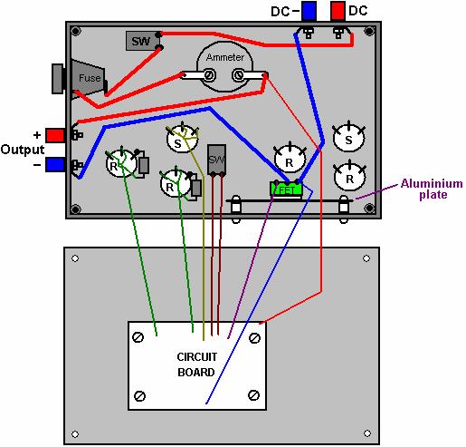
7 Circuit operation: Each NE555 timer chip is placed in an oscillator circuit which has both variable pulse rate ( frequency ) and variable Mark/Space ratio which does not affect the frequency. These oscillator circuits also have three frequency ranges which can be selected by a rotary switch. The variable resistors each have a 100 ohm resistor in series with them so that their combined resistance cannot fall below 100 ohms. Each oscillator circuit has its supply de-coupled by placing a 100 microfarad capacitor across the supply rails and feeding the capacitor through a 100 ohm resistor. This has the effect of reducing any pulsing being carried along the battery connections to affect the adjoining circuit. The first NE555 circuit has fairly large capacitors which give it comparatively slow pulses, as represented by the waveform shown above it. The output from that NE555 is on pin 3 and can be switched to feed the waveform to pin 4 of the second NE555 timer. This gates the second, higher frequency oscillator On and Off to produce the output waveform shown just below the pipe electrodes. The switch at pin 3 of the first NE555 allows the gating to be switched off, which causes the output waveform to be just a straight square wave of variable frequency and Mark/Space ratio. The output voltage from pin 3 of the second NE555 chip is reduced by the 220 ohm / 820 ohm resistor combination. The transistor acts as a current amplifier, capable of providing several amps to the electrodes. The 1N4007 diode is included to protect the MOSFET should it be decided at a later date to introduce either a coil ( inductor ) or a transformer in the output coming from the MOSFET, as sudden switching off of a current through either of these could briefly pull the drain connection a long way below the 0 Volt line and damage the MOSFET, but the 1N4007 diode switches on and prevents this from happening by clamping the drain voltage to -0.7 volts if the drain is driven to a negative voltage. The BUZ350 MOSFET has a current rating of 22 amps so it will run cool in this application. However, it is worth mounting it on an aluminium plate which will act both as the mounting and a heat sink. The current draw in this arrangement is particularly interesting. With just one tube in place, the current draw is about one amp. When a second tube is added, the current increases by less than half an amp. When the third is added, the total current is under two amps. The fourth and fifth tubes add about 100 milliamps each and the sixth tube causes almost no increase in current at all. This suggests that the efficiency could be raised further by adding a large number of additional tubes, and as the gas is produced inside the tubes and the outer tubes are connected electrically, they could probably be bundled together. Although the current is not particularly high, a six amp circuit-breaker, or fuse, should be placed between the power supply and the circuit, to protect against accidental short-circuits. If a unit like this is to be mounted in a vehicle, then it is essential that the power supply is arranged so that the electrolyser is disconnected if the engine is switched off. Passing the electrical power through a relay which is powered via the ignition switch is a good solution for this. It is also vital that at least one bubbler is placed between the electrolyser and the engine, to give some protection if the gas should get ignited by an engine malfunction. It is also a good idea for the bubbler(s) lid to be a tight push fit so that it can pop off in the event of an explosion, and so further limit the effect of an accident. A possible component layout is shown here:


8 The underside of the stripboard is shown here:

9

10 Component Quantity Description Comment 100 ohm resistors 0.25 watt 6 Bands: Brown, Black, Brown 220 ohm resistor 0.25 watt 1 Bands: Red, Red, Brown 820 ohm resistor 0.25 watt 1 Bands: Gray, Red, Brown 100 mf 16V capacitor 2 Electrolytic 47mF 16V capacitor 1 Electrolytic 10 mf 16V capacitor 1 Electrolytic 1 mf 16 V capacitor 1 Electrolytic 220 nf capacitor (0.22 mf) 1 Ceramic or polyester 100 nf capacitor (0.1 mf) 1 Ceramic or polyester 10 nf capacitor (0.01 mf) 3 Ceramic or polyester 1N4148 diodes 4 1N4007 diode 1 FET protection NE555 timer chip 2 BUZ350 MOSFET 1 Or any 200V 20A n-channel MOSFET 47K variable resistors 2 Standard carbon track Could be screw track 10K variable resistors 2 Standard carbon track Could be screw track 4-pole, 3-way switches 2 Wafer type Frequency range 1-pole changeover switch 1 Toggle type, possibly sub-miniature Any style will do 1-pole 1-throw switch 1 Toggle type rated at 10 amps Overall ON / OFF switch Fuse holder 1 Enclosed type or a 6A circuit breaker Short-circuit protection Veroboard 1 20 strips, 40 holes, 0.1 inch matrix Parallel copper strips 8-pin DIL IC sockets 2 Black plastic, high or low profile Protects the 555 ICs Wire terminals 4 Ideally two red and two black Power lead connectors Plastic box 1 Injection moulded with screw-down lid Mounting nuts, bolts and pillars 8 Hardware for 8 insulated pillar mounts For board and heatsink Aluminium sheet 1 About 4 inch x 2 inch MOSFET heatsink Rubber or plastic feet 4 Any small adhesive feet Underside of case Knobs for variable resistors etc. 6 1/4 inch shaft, large diameter Marked skirt variety Ammeter 1 Optional item, 0 to 5A or similar Sundry connecting wire 4 m Various sizes As mentioned earlier, it is absolutely vital that every precaution be taken to avoid an explosion. The hydroxy gas produced by the electrolysis of water is mainly hydrogen gas and oxygen gas mixed together in the ideal proportions for them to recombine to form water again. That happens when the gasses are lit, and as the flame front of the ignition is about 1,000 times faster than the flame front when petroleum vapour is ignited, standard flash-back protection devices just do not work. The best protection device is a bubbler which is a simple container which feeds the gas up through a column of water. It is also a good idea to use a pressure-activated switch which disconnects the power to the electronics if the gas pressure exceeds, say, five pounds per square inch, as shown here: If it is intended to use the electrolyser to feed an internal combustion engine, then the timing of the spark will need to be adjusted, and if the engine is very small and has a waste spark, then that needs to be dealt with as well. These details are covered in the D9.pdf document which forms part of this set of documents. If it is intended to burn the hydroxy gas for heating or cooking applications, then there is a problem. Hydrogen gas burns at such a high temperature that it will melt or cut through most metals. Stan Meyer
11 found this to be a problem and he patented a simple solution for lowering the temperature of the flame by mixing in both air and burnt gasses: Here, the incoming gas is fed into the burner via a valve 35. The burning gas rises through a vertical tube 63 and as it does, it draws in outside air through vents 70 and 13 (which has a sliding cover to control the amount of air entering). A pipe cap 40 collects some of the burnt gasses and feeds them back through pipe 45 to mix in with the gasses in the burner column. The amount of gasses passed back is controlled by valve 42, and the larger the amount of gas being passed back, the lower the temperature generated by the burner.
THE BATTERY CHARGER OF RON PUGH
 THE BATTERY CHARGER OF RON PUGH THANKS IS DUE TO RON PUGH WHO HAS KINDLY SHARED THE CONSTRUCTION DETAILS OF HIS VERY SUCCESSFUL BATTERY CHARGER WHICH IS COP=13 WHEN OPERATING AT 24 VOLTS. IF YOU DECIDE
PEOPLE ARE FAMILIAR WITH THE CONCEPT OF RUNNING A LIGHT FROM A BATTERY AND THEN RECHARGING THE BATTERY USING A SOLAR PANEL OR A WIND-POWERED GENERATOR
 A Perpetual Light PEOPLE ARE FAMILIAR WITH THE CONCEPT OF RUNNING A LIGHT FROM A BATTERY AND THEN RECHARGING THE BATTERY USING A SOLAR PANEL OR A WIND-POWERED GENERATOR. HOWEVER, WE REALLY WANT TO BE ABLE
Simple Free-Energy Devices
 Simple Free-Energy Devices There is nothing magic about free-energy and by free-energy I mean something which produces output energy without the need for using a fuel which you have to buy. Chapter 4:
Using your Digital Multimeter
 Using your Digital Multimeter The multimeter is a precision instrument and must be used correctly. The rotary switch should not be turned unnecessarily. To measure Volts, Milliamps or resistance, the black
Chapter 19: A Small Self-Powered Generator
 A Practical Guide to Free-Energy Devices Author: Patrick J. Kelly Chapter 19: A Small Self-Powered Generator A free-energy developer working in South Africa where it is difficult to find electronic components,
Contents. DX Ignition Page 2
 Contents 1.0 Intent 2.0 Specifications 3.0 Installation 4.0 Operation Precautions 5.0 Repair 6.0 Parts List 7.0 Glossary of Terms 8.0 Contact Information DX Ignition Page 2 1.0 Intent The purpose of this
1. Replace the plugs with the cheap Autolite (25) copper-core plugs, set to 80 thou gap.
 copper-core plugs, set to 80 thou gap.") A recently encountered e-mail from Robert Calloway states that Tesla s bi-filar series-connected coil is effective in picking up radiant energy. In the light of that, and in the absence of further information
A recently encountered e-mail from Robert Calloway states that Tesla s bi-filar series-connected coil is effective in picking up radiant energy. In the light of that, and in the absence of further information
MODEL ELC-12/40-CVM-D BATTERY CHARGER
 NATIONAL RAILWAY SUPPLY MODEL ELC-12/40-CVM-D BATTERY CHARGER Installing, Operating and Service Instructions for the ELC-12/40-CVM-D Solid State Charger PLEASE SAVE THESE IMPORTANT SAFETY AND OPERATING
THE MOTOR/GENERATOR OF ROBERT ADAMS
 THE MOTOR/GENERATOR OF ROBERT ADAMS WHEN HE WAS 70 YEARS OLD, ROBERT ADAMS OF NEW ZEALAND DESIGNED A VERY EFFECTIVE MOTOR/GENERATOR. HE WAS TOLD TO DESTROY HIS DEVICE OR HE WOULD BE KILLED. ROBERT DECIDED
Smack s Booster. The Safety Gear
 Smack s Booster The Smack s Booster is a piece of equipment which increases the mpg performance of a car or motorcycle, and reduces the harmful emissions dramatically. It does this by using some current
POWER SUPPLY MODEL XP-800. TWO AC VARIABLE VOLTAGES; 0-120V and 7A, PLUS UP TO 10A. Instruction Manual. Elenco Electronics, Inc.
 POWER SUPPLY MODEL XP-800 TWO AC VARIABLE VOLTAGES; 0-120V and 0-40V @ 7A, PLUS 0-28VDC @ UP TO 10A Instruction Manual Elenco Electronics, Inc. Copyright 1991 Elenco Electronics, Inc. Revised 2002 REV-I
CHAPTER 6 IGNITION SYSTEM
 CHAPTER 6 CHAPTER 6 IGNITION SYSTEM CONTENTS PAGE Faraday s Law 02 The magneto System 04 Dynamo/Alternator System 06 Distributor 08 Electronic System 10 Spark Plugs 12 IGNITION SYSTEM Faraday s Law The
Systems: Electronics
 Systems: Electronics Resistors & Capacitors Units for resistors and capacitors size/component small large resistance ohm kilohm megaohm capacitance picofarad microfarad farad current milliampere Ampere
Simple Free-Energy Devices
 Simple Free-Energy Devices This presentation is mainly for people who have never come across free-energy and know nothing about it. So, each chapter deals with just one device and tries to explain it clearly.
MODEL ELC-12/60-D BATTERY CHARGER
 *32198* NATIONAL RAILWAY SUPPLY Installing, Operating and Service Instructions for the 12/60 Solid State Charger MODEL ELC-12/60-D BATTERY CHARGER PLEASE SAVE THESE IMPORTANT SAFETY AND OPERATING INSTRUCTIONS
BATTERY CHARGING SYSTEMS
 BATTERY CHARGING SYSTEMS BATTERIES ARE CHARGED BY APPLYING A HIGH ENOUGH VOLTAGE TO THEM. BUT THE RATE OF CHARGE IS NOT CONSTANT. IN THE FIRST SPLIT SECOND, THE VERY LIGHT ELECTRONS FROM THE CHARGING SOURCE
HHO IS A COMMON NAME GIVEN TO THE GAS MIXTURE PRODUCED DURING THE ELECTROLYSIS OF WATER
 HHO Technology Disclaimer: This presentation is for information purposes only and must not under any circumstances be considered to be an encouragement that you should construct anything based on this
Tip: LED Lighting for the 4367 SBB Euro City Set, 4366 and 4368 Cars Date: , Corrections Modified , Photos
 Hi All, I have had the 4367 SBB Euro City set with extra cars 4366 and 4368 since 1998, apart from a test run on the layout they have stayed in storage ever since. I decided to change some rolling stock
Error codes Diagnostic plug Read-out Reset Signal Error codes
 Error codes Diagnostic plug Diagnostic plug: 1 = Datalink LED tester (FEN) 3 = activation error codes (TEN) 4 = positive battery terminal (+B) 5 = ground Read-out -Connect LED tester to positive battery
Electrical Systems. Introduction
 Electrical Systems Figure 1. Major Components of the Car s Electrical System Introduction Electricity is used in nearly all systems of the automobile (Figure 1). It is much easier to understand what electricity
Understanding The HA2500's Horiz Driver Test
 Understanding The HA2500's Horiz Driver Test Horizontal output stage symptoms and component failures are often caused by problems in the horizontal driver stage. The horizontal driver stage is seldom suspected,
A Self-Powered Generator
 A Self-Powered Generator A free-energy developer who prefers to remain anonymous and who lives in South Africa, has very kindly shared the details of his compact self-powered generator so that you can
Professional Wireless Products
 Page 1 of 6 093115 Communications Power Supply and Battery Management Controller Page 2 of 6 1.0 Introduction The 093115 is a 13.8 volt 15amp transformer isolated switch mode down converter designed to
ELECTRICAL. CDTA Technical Training Center
 ELECTRICAL ATOMIC STRUCTURE Protons positive charge Electron negative charge Neutron - neutral Electricity is the movement of electrons from atom to atom ELECTRON FLOW CONDUCTOR - Materials which have
1.0 Installation Wiring
 1.0 Installation Wiring DX Firebox is designed to be an electronic replacement for Pontiac & Ford buzz coils when operated on DC. Installation may be positive or negative ground. Simply observe the RED
Circuit Basics and Components
 Circuit Basics Electric circuits are arrangements of conductors and components that permit electrical current to flow. A circuit can be as simple as a battery and lamp or as sophisticated as a computer.
3 Slot Payphone Controller
 S Coin Controller 2A Information on your Telephone For Your Records Manufacturer Date of Original Manufacture Drawing Reference One of the original patents --- US 2,043,201 This Telephone is Property of
Smack s Booster. The Safety Gear
 Smack s Booster The Smack s Booster is a piece of equipment which increases the mpg performance of a car or motorcycle, and reduces the harmful emissions dramatically. It does this by using some current
THE TORQUE GENERATOR OF WILLIAM F. SKINNER
 THE TORQUE GENERATOR OF WILLIAM F. SKINNER IN 1939, WHICH WAS THE START OF WORLD WAR TWO, WILLIAM SKINNER OF MIAMI IN FLORIDA DEMONSTRATED HIS FIFTH-GENERATION SYSTEM WHICH WAS POWERED BY SPINNING WEIGHTS.
Charles Flynn s Permanent Magnet Motor.
 Charles Flynn s Permanent Magnet Motor. Patent US 5,455,474 dated 3rd October 1995 and shown in full in the Appendix, gives details of this interesting design. It says: This invention relates to a method
Hydrogen Power Systems, Inc.
 Hydrogen Power Systems, Inc. Reducing Fuel Expense and Pollution for Internal Combustion Engines Escondido, California 855-477-1776 www.hpstech.com Page 1 of 23 Introducing the HPS Series of fully assembled
The Physics of the Automotive Ignition System
 I. Introduction This laboratory exercise explores the physics of automotive ignition systems used on vehicles for about half a century until the 1980 s, and introduces more modern transistorized systems.
Tri-Spark Ignition System Installation Triple Cylinder TRI-0001
 Tri-Spark Ignition System Installation Triple Cylinder TRI-0001 There are potentially lethal high voltages produced at the ignition coils and spark plugs, therefore every precaution must be taken to prevent
SECTION M. ELECTRICAL. Section Description Page No.
 SECTION M. ELECTRICAL. Section Description Page No. M.1 General Page 2 M.2 Alternator Page 2 M.3 Battery Page 7 M.4 Hazard Warning System Page 7 M.5 Brake Fail Warning System Page 8 M.6 Seat Belt Warning
FC/FCA 12, 24, 32 & 48 VOLT, 6 & 10 AMP BATTERY CHARGER OPERATION & MAINTENANCE GUIDE
 FC/FCA 12, 24, 32 & 48 VOLT, 6 & 10 AMP BATTERY CHARGER OPERATION & MAINTENANCE GUIDE SENS part number: 101037 Document revision: A Engineering change number: 105073 Date: 1/13/2006 1840 Industrial Circle
Pump ED 101. Power Factor (Part 2) - - Electricity Behaving Better
 - - Electricity Behaving Better") Pump ED 101 Power Factor (Part 2) - - Electricity Behaving Better Joe Evans, Ph.D http://www.pumped101.com Last month we took a close look at the flow of voltage and current in purely resistive and inductive
Pump ED 101 Power Factor (Part 2) - - Electricity Behaving Better Joe Evans, Ph.D http://www.pumped101.com Last month we took a close look at the flow of voltage and current in purely resistive and inductive
Automatic taper of charge rate for superior battery life through good equalization of cells and low water use rate.
 FEATURES Automatic taper of charge rate for superior battery life through good equalization of cells and low water use rate. Silicon diodes with inherent surge protection operated at a conservative percentage
The Electrical System. by Kate Elfers and Mun Yong Jang
 The Electrical System by Kate Elfers and Mun Yong Jang Important links: Video overview of system: https://www.youtube.com/watch? v=w94iksaqwuo Understanding AC vs DC animation: https://www.youtube.com/watch?
WORKSHOP MANUAL ELECTRICITY
 WORKSHOP MANUAL ELECTRICITY GB reference : 754282 DC/ATR 04/2000 1. Electric units:...2 2. Key formulae to remember:...2 3. Definitions:...3 4. Elements:...4 Resistances:...4 Lights:...5 Condensers:...5
Hydro-wind Education Kit ASSEMBLY GUIDE
 Hydro-wind Education Kit ASSEMBLY GUIDE Model No.: FCJJ-26 Warning To avoid the risk of property damage, serious injury or death: This kit should only be used by persons 12 years old and up, and only under
LED Flasher. R1 R2 100 F + C1 100 F +
 LED Flasher. Specification Operates from a 6-12V supply. Alternately flashes two LEDs. Flash rate adjustable by changing the capacitor values and the 10k resistor values. Circuit Diagram 9V LED1 470 TR1
Build Instructions and User Guide
 Build Instructions and User Guide Getting Started To build the Rock Drill 4069 you will need: Solder Wire Cutters Soldering Iron Small pliers The kit is suitable for beginners or more experienced builders
EXPERIMENT - 1 OHM S LAW
 NOTE: While you copy the practical record see that you are following the note. Write Aim, theory, materials required, procedure, results, discussion and precautions on the right side of your record. While
ECO-6 & Installation Manual
 ECO-6 & Installation Manual For the SPA4-RFR Upgrade Kit To upgrade SPA4 amplifiers v1.00 & v1.01 to v2.0 Some sections also apply to the PA1, PA2, and PA3 14 August 2015 2015 by Ralph Hartwell Spectrotek
SCA-80(Q) C11 REPLACEMENT ASSEMBLY MANUAL
 C11 REPLACEMENT ASSEMBLY MANUAL") SCA-80(Q) C11 REPLACEMENT ASSEMBLY MANUAL 2014-2016 AkitikA, LLC All rights reserved Revision 1p05 July 3, 2016 Page 1 of 15 Table of Contents Table of Contents... 2 Table of Figures... 2 Section 1: About
SCA-80(Q) C11 REPLACEMENT ASSEMBLY MANUAL 2014-2016 AkitikA, LLC All rights reserved Revision 1p05 July 3, 2016 Page 1 of 15 Table of Contents Table of Contents... 2 Table of Figures... 2 Section 1: About
Harbach Soft Key (sk-220) Installation Instructions for the Heathkit SB-220
 Installation Instructions for the Heathkit SB-220") Harbach Soft Key (sk-220) Installation Instructions for the Heathkit SB-220 Step-by-Step Instructions with Photos Based on an install by W4HDM Installation & Photos by W4HDM Instructions from http://www.harbachelectronics.com/
Harbach Soft Key (sk-220) Installation Instructions for the Heathkit SB-220 Step-by-Step Instructions with Photos Based on an install by W4HDM Installation & Photos by W4HDM Instructions from http://www.harbachelectronics.com/
amperometric (currentbased) cell coupled with a potentiometric
 cell coupled with a potentiometric") 26 July 213 WIDE-RANGE AIR/FUEL SENSORS: FROM THE INSIDE OUT BY BERNIE THOMPSON The construction and operation of the six-wire, wide-range air/fuel ratio (WRAF) sensor are entirely different from a conventional
26 July 213 WIDE-RANGE AIR/FUEL SENSORS: FROM THE INSIDE OUT BY BERNIE THOMPSON The construction and operation of the six-wire, wide-range air/fuel ratio (WRAF) sensor are entirely different from a conventional
THE FOURTH STATE. Gaining a universal insight into the diagnosis of automotive ignition systems. By: Bernie Thompson
 THE FOURTH STATE Gaining a universal insight into the diagnosis of automotive ignition systems By: Bernie Thompson Did you know that the forth state of matter powers the spark ignition internal combustion
Air Cooled Engine Technology. Roth 9 th Ch 14 Elect. System Service Pages
 Roth 9 th Ch 14 Elect. System Service Pages 245 276 1. is the term used to describe periodic, preventative maintenance done to the ignition system of any engine. It may often times also include fuel system,
PPS20 COMMUNICATIONS POWER SUPPLY AND BATTERY MANAGEMENT SYSTEM
 PPS20 COMMUNICATIONS POWER SUPPLY AND BATTERY MANAGEMENT SYSTEM 2 Table of Contents Introduction:... 3 1.0: Operation Principles:... 3 1.1: Stand alone supply... 3 1.2: Backed up supply:... 3 1.3: Battery
PURE PHYSICS ELECTRICITY & MAGNETISM (PART I)
") PURE PHYSICS ELECTRICITY & MAGNETISM (PART I) 1 A student walks across a thick carpet and becomes positively charged as his shoes rub on the carpet. When he touches the metal handle of a door, negative
PURE PHYSICS ELECTRICITY & MAGNETISM (PART I) 1 A student walks across a thick carpet and becomes positively charged as his shoes rub on the carpet. When he touches the metal handle of a door, negative
3. OPERATION 2.1. RESTRAINT CIRCUIT 2.6. INDICATING CIRCUIT 2.2. OPERATING CIRCUIT 2.7. SURGE PROTECTION CIRCUIT 2.3.
 41-348.1H Type SA-1 2.1. RESTRAINT CIRCUIT The restraint circuit of each phase consists of a center-tapped transformer, a resistor, and a full wave rectifier bridge. The outputs of all the rectifiers are
A Practical Guide to Free Energy Devices
 A Practical Guide to Free Energy Devices Devices Part 9: Created: 12th June 2005. Last updated: 4th March 2011 Author: Patrick J. Kelly This document provides practical information on the construction
Ordinary Level Physics SOLUTIONS: EFFECTS OF AN ELECTRIC CURRENT
 Ordinary Level Physics SOLUTIONS: EFFECTS OF AN ELECTRIC CURRENT Safety Features and kilowatt hours The unit of energy is called the kilowatt hour One kilowatt hour is the amount of energy used by a 1000
MAGNETO REPLACEMENT. Pre-Unit Twin Cylinder Motorcycles. ELECTRONIC IGNITION SYSTEM For 4 Stroke. With 12 VOLT Electrics, POS/ NEG Ground
 Sure ー Fire MAGNETO REPLACEMENT ELECTRONIC IGNITION SYSTEM For 4 Stroke Pre-Unit Twin Cylinder Motorcycles With 12 VOLT Electrics, POS/ NEG Ground SYSTEM TYPE: PAMT1 2 Sure-Fire System Contents: MAGNETO
In this installment we will look at a number of things that you can do with LEDs on your layout. These will include:
 Introduction The first article in this series, LEDs 101 - The Basics, served to review the characteristics and use of LED lighting in a garden railway environment. It also generated a host of questions
BLUE LIGHT FOR DYNACO STEREO 120, SCA-80, OR PAT-4 ROCKER SWITCHES
 BLUE LIGHT FOR DYNACO STEREO 120, SCA-80, OR PAT-4 ROCKER SWITCHES 2014 AkitikA, LLC All rights reserved Revision 1p5 April 8, 2014 Page 1 of 16 Table of Contents Table of Contents... 2 Table of Figures...
General Purpose Flasher Circuit
 General Purpose Flasher Circuit By David King Background Flashing lights can be found in many locations in our neighbourhoods, from the flashing red light over a stop sign, a yellow warning light located
Using Electricity. Summary Notes. 1. From the Wall Socket Household appliances. Earth wire and safety.
 Using Electricity Summary Notes Section Content 1. From the Wall Socket Household appliances. Earth wire and safety. 2. Alternating and Direct Battery and transformer. Current Circuit diagrams. Current
Battery Back-up Model: BBM-1225
 Battery Back-up Model: BBM-1225 Owner's Manual Please read this manual before operating your INDEX Safety instructions... 2 Description... 2 Principle of operation...3,4,5,6 Installation... 7,8 Specifications...
Art. No. EC-315. Art. No. EC-330. Art. No. EC-340 SWITCH-MODE BATTTERY CHARGER CONTENTS IMPORTANT SAFETY PRECAUTIONS... 2
 SWITCH-MODE BATTTERY CHARGER CONTENTS IMPORTANT SAFETY PRECAUTIONS... 2 DESCRIPTION AND FEATURES... 3 CHARGING STAGES... 4 Art. No. EC-315 Art. No. EC-330 Art. No. EC-340 PROTECTIONS... 5 INSTALLATION...
B How much voltage does a standard automobile battery usually supply?
 Chapter 2 B-003-16-01 How much voltage does a standard automobile battery usually supply? 1. About 240 volts 2. About 120 volts 3. About 12 volts 4. About 9 volts B-003-16-02 Which component has a positive
Cruise Control Wiring
 Cruise Control Wiring By Matt Sandt, Revised 3-28-16 The approach described in this writing applies to solar car motor controls which use a potentiometer connected to a gas pedal. The potentiometer is
A Practical Guide to Free Energy Devices
 A Practical Guide to Free Energy Devices Part PatE12: Last updated: 28th January 2006 Author: Patrick J. Kelly Please note that this is a re-worded excerpt from this patent. It describes the water-splitting
This year Märklin have released a coach which has included LED lighting with a currentconducting close coupler (single pole)
") Hi All, Over the past few months I have been working at a steady pace to install LED lighting in my passenger coaches. The coach lighting must have LED lights to reduce power consumption on the layout
Hi All, Over the past few months I have been working at a steady pace to install LED lighting in my passenger coaches. The coach lighting must have LED lights to reduce power consumption on the layout
2.0 CONSTRUCTION 3.0 OPERATION. SA-1 Generator Differential Relay - Class 1E 2.5 TRIP CIRCUIT
 41-348.11C SA-1 Generator Differential Relay - Class 1E 2.0 CONSTRUCTION The type SA-1 relay consists of: Restraint Circuit Sensing Circuit Trip Circuit Surge Protection Circuit Operating Circuit Amplifier
Today, we re going to talk about battery safety. We ll discuss all the key issues associated with using batteries safely, including battery hazards,
 Today, we re going to talk about battery safety. We ll discuss all the key issues associated with using batteries safely, including battery hazards, battery charging, and battery maintenance. Although
QUASAR ELECTRONICS KIT No ELECTRONIC CAR IGNITION
 QUASAR ELECTRONICS KIT No. 1058 ELECTRONIC CAR IGNITION General Description The advantages of having an electronic ignition in your car are well known. Let us mention them again: 1. Perfect burning of
ELECTRICITY KIT - for DC and AC
 ELECTRICITY KIT - for DC and AC Cat: EM1763-001 KIT LAYOUT 1 GENERAL DESCRIPTION: This kit is designed to perform important basic experiments with electricity. To study electric circuits, switches, lamps,
CURTIS TRANSISTOR MOTOR CONTROLLER
 CURTIS TRANSISTOR MOTOR CONTROLLER W40-60XL, B40-60XL [D135]; N30FR [A217]; R30ES [B174]; R30XMS [C174]; R30XMS2 [D174]; W60-80XT [E135]; B60-80XT [B199]; C60-80XT [B199]; W40XT [A218]; W45XT [A215, B215];
PRO6.4, PRO6.4E, PRO9.0, PRO9.0E Generator Service Manual
 PRO6.4, PRO6.4E, PRO9.0, PRO9.0E Generator Service Manual IMPORTANT: Read all safety precautions and instructions carefully before operating equipment. Ensure equipment is stopped and level before performing
Auger System - Troubleshooting Guide
 Haas Technical Documentation Auger System - Troubleshooting Guide Scan code to get the latest version of this document Translation Available 1. Multi Auger 2. Single Auger Electrical Diagram Copyright
Portable 12V Jump Start Device Powered By KrankingKAP Supercapacitors REV. A
 KrankingKART Mini HD Portable 12V Jump Start Device Powered By KrankingKAP Supercapacitors REV. A Protected by one or more of the following U.S. Patents US 6,819,010 B2 US 6,871,625,B1 US 6,988,475 B2
Battery Back-up BBM Owner's Manual. Please read this manual BEFORE installing your inverter
 Battery Back-up BBM-1225 Owner's Manual Please read this manual BEFORE installing your inverter owner's MAnUAL index section 1 Safety Instructions... 3 section 2 Layout and Dimensions... 4 section 3 Description
Installation Operation Parts
 OWNER S MANUAL BATTERY BACKUP SUMP Installation Operation Parts For further operating, installation or maintenance assistance, Call 98-8-05 PRINTED IN U.S.A. M-8 (/9) RULES FOR SAFE INSTALLATION AND OPERATION
An unwritten rule says that when a. Cures for a sick spot welding machine. Figure 1. To test the secondary of the welding machine,
 Figure 1 To test the secondary of the welding machine, the power should be turned off. With the electrodes open, the continuity between the top and bottom electrodes should be checked. Cures for a sick
Renewable Energy Education Set ASSEMBLY GUIDE
 Renewable Energy Education Set ASSEMBLY GUIDE Model No.: FCJJ-27 Warning To avoid the risk of property damage, serious injury or death: This kit should only be used by persons 12 years old and up, and
CSDA Best Practice. Hi-Cycle Concrete Cutting Equipment. Effective Date: Oct 1, 2010 Revised Date:
 CSDA Best Practice Title: Hi-Cycle Concrete Cutting Equipment Issue No: CSDA-BP-010 : Oct 1, 2010 Revised : Introduction Hi-cycle/high frequency concrete cutting equipment has become more prevalent in
PLASMA CUTTER OWNER`S MANUAL MODEL : CUT 40/60. (POWER v-mos CONTROLIED, PLASMA CUTTING POWER SUPPLY)
") PLASMA CUTTER OWNER`S MANUAL MODEL : CUT 40/60 (POWER v-mos CONTROLIED, PLASMA CUTTING POWER SUPPLY) PRODUCTS INTRODUCTION Congratulations for your purchase. CUT 40,CUT 60 are made by international most
PLASMA CUTTER OWNER`S MANUAL MODEL : CUT 40/60 (POWER v-mos CONTROLIED, PLASMA CUTTING POWER SUPPLY) PRODUCTS INTRODUCTION Congratulations for your purchase. CUT 40,CUT 60 are made by international most
11.1 CURRENT ELECTRICITY. Electrochemical Cells (the energy source) pg Wet Cell. Dry Cell. Positive. Terminal. Negative.
 pg Wet Cell. Dry Cell. Positive. Terminal. Negative.") Date: SNC1D: Electricity 11.1 CURRENT ELECTRICITY Define: CIRCUIT: path that electrons follow. CURRENT ELECTRICITY: continuous flow of electrons in a circuit LOAD: device that converts electrical energy
Date: SNC1D: Electricity 11.1 CURRENT ELECTRICITY Define: CIRCUIT: path that electrons follow. CURRENT ELECTRICITY: continuous flow of electrons in a circuit LOAD: device that converts electrical energy
DIY Synth Kit - Manual
 DIY Synth Kit - Manual Welcome to the DIY Synth - Manual This is a step-by-step guide to making your own electronic Synth. All the equipment you ll need to make your synth is your DIY Synth kit and of
Modifications to the TS-930 Power Supply. Ken Grant, VE3FIT
 Modifications to the TS-930 Power Supply Ken Grant, VE3FIT My TS-930 has a serial number in the 5 million and uses a +21.7 Volt low-current regulator as well as the normal +28.5 V high current supply.
350 Watt Vacuum Tube Amplifier. Owner s Manual
 350 Watt Vacuum Tube Amplifier Owner s Manual CIRCUIT DESCRIPTION The input stage consists of a 12AX7 current sourced long-tailed balanced pair, which is direct coupled to a second long-tailed balanced
HOW TO MAKE YOUR OWN BATTERIES
 HOW TO MAKE YOUR OWN BATTERIES 1 Page TABLE OF CONTENTS Introduction....3 Usage....4 Aluminum Can Batteries/Cells....8 A Long Lasting, Yet Powerful Battery....10 PVC Pipe Batteries...13 Lab Notes....17
WIRING THE HEATER POWER SUPPLY
 WIRING THE HEATER POWER SUPPLY Fig. 14 13/14 Take the longer PS board (with the 47R resistors and the fuse) and, using M3x6 screws, fix it to the chassis to the left of the mains transformer. The diodes
Doubloon Two Bus Power Supply
 Doubloon Two Bus Power Supply Augustica w w w. a u g u s t i c a. c o m DANGER This power supply kit uses high-voltage and therefore may produce a lethal shock. Only persons who are competent at electronics
SERVICE SHOP NOTES. Use ohmmeter to check the resistance between the leads.
 SERVICE SHOP NOTES LIMA MAC SELF VOLTAGE REGULATED GENERATORS Troubleshooting Tips Symptom: Engine bogs down or stalls even at no load. Problem: Main stator has one or more taps wound or connected incorrectly.
BASIC ELECTRICAL MEASUREMENTS By David Navone
 BASIC ELECTRICAL MEASUREMENTS By David Navone Just about every component designed to operate in an automobile was designed to run on a nominal 12 volts. When this voltage, V, is applied across a resistance,
(2 DPDT 2 4 X
 Dynaco ST-120 with VTA driver board Kit instruction manual Triode/Pentode version Congratulations on your purchase of the Dynaco ST-120 with VTA driver board kit. Every effort has been made to give you
CHAPTER 2. Current and Voltage
 CHAPTER 2 Current and Voltage The primary objective of this laboratory exercise is to familiarize the reader with two common laboratory instruments that will be used throughout the rest of this text. In
Repair of warped dial scale - Sony CRF-5090.
 Repair of warped dial scale - Sony CRF-5090. Apparently this is quite a common problem with this series of receivers. This one was bought on a local auction site where it was clearly advertised as having
C capacitance, 91 capacitors, codes for, 283 coupling, polarized and nonpolarized,
 Index Numbers and Symbols 555 timer, 164 166 making sound using, setting output speed of, 166 167 using for reaction game speed, 260 261 μf (microfarad), 92 Ω (ohms), 7, 70 A A (amperes), 7 AC (alternating
Dual Voltage Solar Power Charge Controller Board Connection & Operation V2.xx
 Dual Voltage Solar Power Charge Controller Board Connection & Operation V2.xx Connection Instructions 1) Mount Board to a panel (Wood or Metal) using supplied spacers and screws. 2) Solar Start up 18 volts,
AC-DC Converter Application Guidelines
 AC-DC Converter Application Guidelines 1. Foreword The following guidelines should be carefully read prior to converter use. Improper use may result in the risk of electric shock, damaging the converter,
CHAPTER 10 ELECTRIC SYSTEM
 CHAPTER 10 ELECTRIC SYSTEM 1. ELECTRIC SYSTEM ELECTRIC SYSTEM 1.1 WIRING DIAGRAM CK20-USA 196WA00A S196-WOO Jul. 2003 10-3 CK20(M) CHAPTER 10 CK20-EU 196WA51A 10-4 S196-WOO Jul. 2003 ELECTRIC SYSTEM 1.2
Automotive Parts. Charging & Starting Systems
 Automotive Parts Charging & Starting Systems Charging Systems Output voltage kept to about 2 volts higher than battery voltage Controlled by varying current into rotor field winding (voltage regulator
Reversing Hand Throttle and Horn Relay Board RBT / HRB
 Instruction Manual Reversing Hand Throttle and Horn Relay Board RBT / HRB Contents Section Page Section Page 1. Introduction... 2 2. Do's and Don ts... 2 3. Horn Relay Board... 3 3.1 HRB Versions... 3
DIY Synth Kit - Manual STUTTER SYNTH
 DIY Synth Kit - Manual STUTTER SYNTH Welcome to the DIY Synth - Manual This is a step-by-step guide to making your own electronic Synth. All you will need is your hands and your DIY Synth kit which includes
Unit AE01K Knowledge of Locating and Correcting Simple Electrical Faults in the Automotive Workplace
 Assessment Requirements Unit AE01K Knowledge of Locating and Correcting Simple Electrical Faults in the Automotive Workplace Content: Basic electrical principles a. Explain the direction of current flow
The graphs show the voltage across two different types of cell as they transfer the last bit of their stored energy through the torch bulb.
 Q1. A small torch uses a single cell to make the bulb light up. (a) The graphs show the voltage across two different types of cell as they transfer the last bit of their stored energy through the torch