E-TON VIPER OWNER S MANUAL. Viper 70, Viper 70M, and Viper 90R with 4 Cycle Engines. Copyright ETON America, all rights reserved.
|
|
|
- Alan Johns
- 6 years ago
- Views:
Transcription

1 E-TON VIPER OWNER S MANUAL Viper 70, Viper 70M, and Viper 90R with 4 Cycle Engines
2 Important Notices READ and UNDERSTAND this owner s manual Both the operator and the adult supervisor should completely read and understand this owner s manual before operating this vehicle. This owner s manual will instruct you in the safe operation of the vehicle. NO Passengers This vehicle was designed for operation ONLY by the operator, (Driver). The load limit and seat configuration is designed for the operator ONLY. It is not safe to carry passengers on the vehicle. ADULT Supervision and Instruction are REQUIRED. This vehicle MUST NOT be operated by a youth without Adult supervision and instructions. Unattended operation without adult supervision could result in injuries. E-TON recommends that both the operator and the adult supervisor attend an ATV safety instruction course. ALWAYS Wear Protective Clothing While operating this vehicle, the driver must always wear protective clothing. Protective helmet with face shield, elbow and knee pads, long leg pants, gloves and hard soled boots should always be worn when operating this vehicle. OFF ROAD Use ONLY This vehicle is designed and manufactured for off-road use only. Operation on public streets, roads or highways is illegal and very dangerous. OBEY all State and local laws and regulations Each state and local governing agency has laws and regulations for ATV operations. It is the owner s responsibility to know, understand and obey these laws and regulations. SPEED RESTRICTION Devices This vehicle is equipped with electronic speed limiting devices. Any attempt to change, over-ride or bypass these devices may cause dangerous operating conditions. Age Recommendations by model size ATV Model Size ETON Models Minimum Age Weight Capacity Under 70cc RXL-40E RXL-70M 6 years and older 70 Lbs RXL cc RXL-90 RXL-90R 12 years and older 200 Lbs over 90cc CXL-150R RXL-150R VXL-250R 16 years and older 250 Lbs 250 Lbs 350 Lbs Page 1
3 Table of Contents Safety Notes...3 Additional safety tips:...6 Vehicle Identification Numbers...7 Controls, Switches & Feature Locations...7 Engine Stop Switch (5)...8 Manual choke lever (9)...8 Throttle lever...8 Front and Rear Brakes...9 Parking Brake...9 Safety Tether Switch...9 Remote Stop/Start Switch...9 Fuel Tank...10 Fuel Valve...10 Inline Fuel Filter...11 Engine Oil...11 Checking the engine oil level...11 Changing the engine oil...12 Transmission...12 Gear Changing...12 Changing the transmission oil...13 To change the Transmission oil on your E-TON engine, follow these steps:...13 Tires and Wheels...15 Tire & Wheel Inspection...15 Tire Pressure...15 Spark Plug...15 Exhaust System Maintenance...15 Muffler Cleaning...15 Spark Arrestor Screen...16 Air Filtration System...16 Air Filter Maintenance...16 To clean the filter...16 Braking Systems...17 Front Brake System Inspection...17 Brake Adjustment...17 Rear Brake System Inspection...18 Fill Master Brake Cylinder Reservoir...18 Purging Brake Lines...19 Drive Chain...19 Chain Slack Adjustment...19 Throttle Lever...20 Adjusting the throttle cable...20 Electrical Battery...20 Pre-Operation Inspection...21 Starting Procedure...21 Driving your ATV...21 Turning your ATV...22 Parking Your ATV...22 Specifications...23 Maintenance Schedule...25 Owners Maintenance Records...28 Wire diagram Viper 70M (RXL-70M)...29 Wire diagram RXL-90R...30 Warranty...31 Owner s Notes:...33 Page 2


4 Safety Notes 1. Both the adult supervisor and youth operator must fully understand everything in this manual before operating this vehicle. 2. This vehicle was designed for the operator only. NO PASSENGERS should be allowed on this vehicle. 3. This vehicle is designed for operation on level, obstacle free off-road areas. 4. Riding this vehicle on public roads or highways is illegal. If it becomes necessary to cross a public road or highway, the vehicle should be pushed across using extreme caution. 5. This vehicle MUST NOT be operated without adult supervision and instruction. 6. DO NOT operate this vehicle while under the influence of drugs, alcohol or other medication that impairs judgment or coordination. Doing so can result in serious injury or even death. 7. Maintain a safe distance between your vehicle and other vehicles with whom you are riding. 8. READ the owner s manual carefully before riding. 9. ALWAYS wear a helmet, face shield, elbow & knee pads, hard-soled boots, gloves, and protective clothing while operating this vehicle. Page 3

 11.")

5 10. NEVER ride this vehicle unless it has been properly maintained and adjusted. Always perform a pre-ride inspection of your vehicle. Look for wires, bolts and other fasteners that may have come loose on previous rides. Inspect the drive chain, throttle and brakes for proper adjustment and operation. Check the engine oil level in the oil tank. Check fuel level and inspect for fuel leaks. (Remember, you can ride further in 1 hour than you can walk back in 1 day!) 11. WARM UP your body with some exercises before riding. This helps to make you alert and prevent cramping and other discomfort. 12. LEARN TO RIDE this vehicle properly and safely. Have an experienced rider teach you the safe operation of your vehicle. E-TON recommends you take an ATV riding course before you first ride your vehicle. Page 4


6 13. NEVER REFUEL this vehicle when hot. Ask your adult supervisor to refuel your vehicle. Gasoline is extremely flammable and will ignite if spilled on a hot engine or muffler. Never smoke or expose the fuel to an open flame or spark while refueling your vehicle. Always refuel your vehicle in a safe place free of any ignition source. 14. NEVER run the vehicle in an enclosed area. The exhaust gases from the engine contain CARBON MONOXIDE which can be fatal if breathed in high concentrations for an extended time. 15. HOT! The engine and exhaust system on your vehicle become very hot during normal operation. Touching these hot surfaces can cause severe burns. Always assume that your unit s engine and exhaust system are HOT unless you know that they are not. Page 5
7 Additional safety tips: Participate in an approved ATV safety education training program Always provide responsible adult supervision for ATV operators younger than 18 years of age Don't let youngsters ride full-sized ATV's Follow all safety recommendations of the ATV manufacturer Operate ATVs only during daylight Wear a helmet with face protection at all times Operate only four-wheeled ATVs Provide a drug and alcohol free environment Always use the buddy system Avoid riding in areas where contact with automobiles might be possible Drive ATVs on surfaces as recommended by the manufacturer Travel at speeds conducive to conditions and operator abilities Check on the conditions of the trails you will be traveling Know and understand local and state laws governing the use of ATVs Permit only one operator per ATV Insist on a "perfect fit" between the ATV and the physical, mental, and emotional maturity of the operator Use antenna flags and wear bright clothing to increase conspicuity. Use maps and compass if you are riding in an unfamiliar area. Make a mental note of landmarks; you may need them if you are stranded. If you are lost at night, do not move around. You will waste valuable fuel that you can use to ride safety in the daylight. Carry a first-aid pack with you. Carry some snacks and a water supply with you. Carry equipment to handle medical and mechanical emergencies. Your vehicle field repair kit should include the following items; o the manufacturer's tool kit o wire, tape, elastic cords, o possibly locking pliers o and a tow rope. Pre-Ride Inspection - Inspecting the condition of your ATV before each ride is very important to minimize the chance of injury and maximize the enjoyment of your ride. It also helps ensures long term performance of your ATV. Follow the owner s manual guide to inspection and maintenance of your ATV. A well maintained ATV will give you years of enjoyment. Watch out for thin ice which may be camouflaged by snow. Remember, you can ride further in one hour than you can walk in an entire day. Age Recommendations by model size ATV Model Size ETON Models Minimum Age Weight Capacity Under 70cc RXL-40E RXL-70M 6 years and older 70 Lbs RXL cc RXL-90 RXL-90R 12 years and older 250 Lbs over 90cc CXL years and older 250 Lbs 150 cc CXL years and older 300 Lbs Page 6


 3. Throttle lever 4.")
8 Vehicle Identification Numbers Vehicle Identification Number (VIN) is located at the front of the unit under the front fender on a plate mounted between the main frame rails. Engine serial number is located on the left-hand side of the engine on the crankcase housing. Your VIN RFZ Eng. No. Controls, Switches & Feature Locations Locations of controls and features 1. Fuel Tank filler and vent tube 2. Front brake lever (Parking Brake Lock) 3. Throttle lever 4. Rear brake lever 5. Engine stop switch 6. Head lamp switch 7. Horn button 8. Engine starter button 9. Manual Choke Lever Page 7

9 Control Features Engine Stop Switch (5) Throttle lever The stop switch is a red colored rocker switch located on the left-hand handle bar. To start and run the engine, this switch must be placed in the on, Ω, position. The vehicle is also equipped with a safety brake switch which will prevent the engine from starting until the parking brake is engaged. The throttle lever is located on the right-hand handle bar below the grip. To operate the throttle lever, place your right thumb on the lever and press forward to increase your speed. To decrease your speed, reduce your pressure on the lever and the spring tension will automatically reduce your speed. The travel of the throttle lever is controlled by the throttle stop bolt. To stop your engine, place the switch in the stop,, position. In the stop,, position the ignition system is grounded preventing the spark plug from firing. This switch can also be used as a safety or emergency stop switch. Manual choke lever (9) All Viper models are equipped with a manually operated carburetor choke system. This choke is operated by the lever at the bottom of the left hand control switch. When first starting the engine,(cold start), place the lever in the full left position, (Choke closed or on) As the engine warms return the lever to the full right position. (Choke open or off). As your operator gains more experience, you can increase the throttle travel to allow for additional speed to be obtained. To increase the throttle s travel, thus increasing the maximum speed, turn the throttle stop bolt counter clockwise. To decrease the throttle s travel, thus decreasing the maximum speed, turn the throttle stop bolt clockwise. The throttle cable should be adjusted so there is 2mm, (1/8 ) free travel at the lever before the throttle starts to open. Page 8
 (Viper 70M is equipped with rear hydraulic disc brake only) The front brakes are controlled by the long brake lever on the right-handle bar.")

10 Front and Rear Brakes This vehicle is equipped with dual front mechanical drum brakes and a rear hydraulic disc brake. (Viper 70 Viper 90R) (Viper 70M is equipped with rear hydraulic disc brake only) The front brakes are controlled by the long brake lever on the right-handle bar. If your engine fails to start, ensure that the engine stop switch is in the on, Ω, position and that the parking brake is engaged. Safety Tether Switch The Viper 70M and Viper 70 models are equipped with a safety tether switch (optional on The rear brake is controlled by the long lever on the left-handle bar. The rear brake is the primary stopping brake on your vehicle. Using the rear brake to stop your vehicle will prevent steering control loss. Use your front and rear brakes in combination to control your speed while descending a grade. Use caution not to apply too much pressure to your front brakes so that the wheels lock up, stop turning, and causing a loss of steering control. If the front wheels lock up, and stop turning, lightly reduce the pressure on the front brake lever until they unlock and start to turn. Parking Brake The front brake lever has a button located at the pivot point to lock the brake in the, Ω, on position. This should be engaged as a parking brake whenever the vehicle is not in operation. Viper 90R). The switch is located on the left hand side of the handlebars. The switch cap must be fully engaged for the vehicle to start and run. The cap is tied to a tether that should be worn around the rider wrist. In case of an emergency a simple pull on the tether will disengage the switch and stop the engine. Remote Stop/Start Switch The Viper 70M come equipped with a remote Stop/Start key ring switch. (This feature is an optional kit for the Viper 70. A remote Stop Only kit is optional for the Viper 90R). This feature must be engaged in order to start the engine. The brake lever has a safety switch built in to prevent the engine from starting while the brake is disengaged. The remote switch has two buttons, a Stop button which will stop the engine when pressed. The effective range of the switch is 30 feet unobstructed. Page 9


11 Once the unit has been stopped with the remote switch you must press the run button in order for the unit to be restarted. This action resets the remote receiver on the unit. The unit may also be started remotely by pressing both the Stop & Run buttons together. Safety Note: Always test the remote switch before beginning a riding session. The remote switch is operated by a battery which should be replace one a year. You can obtain a replacement battery at your local department store. Fuel Tank the tank to prevent fuel spills. DO NOT allow dirt or other debris to enter the tank when refueling. Replace the cap if damaged or if it will not seal to the tank. Tighten the cap snugly, being careful not to over tighten. Over tightening the cap can cause damage to the cap or seal. The fuel tank capacity is 4.5 liters, 1.2 gal, including a reserve of 0.8 liters, 0.2 gal. Use unleaded automobile gasoline with an octane level of 91 or higher. NEVER REFUEL YOUR ATV when the engine is HOT. Wait 30 minutes after turning off the unit before refueling. Spilling fuel on a HOT engine could cause a fire. Wipe up any fuel spills before re-starting. Fuel Valve The fuel tank fill cap is located on top of the unit just ahead of the seat. The cap contains a vent to prevent a vacuum from forming in the tank as fuel is used. The vent tube must be attached to the cap and inserted in the vent tube holder hole while operating the unit. The fuel cap vent and vent tube must be clean and clear of obstructions for the unit to operate normally. You can check the vent and vent tube by blowing air through the tube. If you can not blow through the vent tube and cap you must clean the vent and tube or replace them. Every time you refuel your unit, check the rubber seal inside the cap for cuts, tears and dirt. Clean or replace the seal if it becomes worn or torn. The seal must be in good condition to insure a proper seal of the cap to The unit is equipped with a three way fuel valve located on the left side of the unit just below the seat. The valve has three settings; OFF, ON and RES. With the valve in the OFF position fuel is held in the tank and is prevented from flowing to the carburetor. The valve should be placed in the OFF position whenever the unit is not being operated. Place the valve in the ON position for Page 10


12 normal operation of the unit. This allows fuel to flow to the carburetor for normal operating. The RES position allows fuel to flow from the small reserve in the tank to allow the unit to be taken to a refueling location. When you have to switch to the RES position you must refuel the unit as soon as possible. ALWAYS CHECK YOUR Fuel level before you start riding your ATV. Remember: You can drive further in one hour on your ATV than you can walk in one day. Inline Fuel Filter returning the clamps to the original position. Turn the fuel valve to the ON position and check for leaks. Inspect the fuel lines for cuts, abrasions and deterioration. Replace fuel lines as needed. DO NOT start or operate the engine if the fuel filter or lines are leaking. Leaking fuel can cause a fire. Engine Oil Your ATV uses an automotive type engine oil to lubricate and cool the engine. The engine oil dip stick is located on the right hand side of the engine just forward of the front chain guard. Your ATV is equipped with an inline fuel filter to prevent dirt and debris from entering the carburetor and engine. Check the filter for dirt or damage before each ride and at each refueling. Replace the filter if dirty or damaged. The filter should be replaced every 600 hours of operation and at the start of each season. To replace the filter, first turn the fuel valve to the OFF position. Then carefully compress the wire clamp rings until the clamp is free of the fuel line. Slide each clamp away from the filter about ¾. Remove the filter from the fuel line by holding the line and pulling the filter. Install the new filter by inserting the filter into the fuel line and DO NOT allow the engine to operate with a low oil level. Doing so will result in extensive damage to your engine. This damage is not covered under the warranty. Checking the engine oil level To check your engine oil level, park the unit on level area. Always check the oil level with the engine off and cold. Checking the oil level in a hot engine can give you a false reading. CAUTION: Removing the oil dipstick while the engine is running can cause hot oil to splash out of the crankcase and cause burns. Page 11


13 Remove the dip stick by turning counter clockwise until the threads are fully disengaged. Pull the dip stick from the crankcase and check the oil level as indicated on the stick. The oil level should fall between the upper and lower limit line on the stick. If the engine oil is low add oil thought the dipstick hole until the dip stick read full or has reached the upper limit line. DO NOT over fill the crankcase as this can result in sever engine damage. Your E-TON engine requires SAE 20W-40 engine oil, and has a crankcase capacity of 70cc Engine = 100cc / 3.4oz 90cc Engine with Reverse = 300cc / 10.2oz Always check the engine oil level before each riding session. Changing the engine oil The engine oil should be change at the beginning of each riding season and at every 100 hours of operation. When operating in dusty our humid conditions the oil should be change more frequently. To change the engine oil in your E-TON engine follow these steps: 1. Place an oil catch pan directly below the engine crankcase. 2. Remove the crankcase drain plug located on the bottom of the crankcase on the underside of the unit. 3. Remove the engine oil dipstick located on the right hand side of the crankcase directly below the transmission shift lever. 4. Allow the oil to drain completely (15-30min). 5. Reinstall the crankcase drain plug and torque to 7-10lb-ft. 6. Fill the crankcase with SAE 20W-40 automotive grade engine oil through the dipstick hole. Engine oil capacity of 800cc / 27oz 7. Reinstall the engine oil dipstick and finger tighten. 8. Dispose of used oil at a proper recycling station as required by law Engine oil capacity of 800cc / 27oz SAE 20W-40 Automotive Engine Oil Transmission Gear Changing (Viper 90R (RX4-90R) ONLY) Page 12

14 The Viper 90R has been programmed to shut the engine off if the shifting procedure described above is not followed. If your engine shut off while shifting it is usually caused by not allowing the engine to reduce to the idle speed or the idle speed is set to high. 1700rpm is the correct idle speed for the Viper 90R. The Viper 90R has a fully automatic C.V.T. transmission with forward and reverse gearing. Selecting either forward or reverse is done by sliding the gear selector switch to the desired position. The transmission is shifted by an electrical motor according to the position of the selector switch. The selector switch has three positions ( F N R ) F = Forward N = Neutral R = Reverse When the transmission is in reverse the Viper 90R will produce an auditable alarm will sound to let you and other near by know that the unit is in reverse. Follow the steps below when shifting directions; 1. Fully apply the left hand brake lever. 2. Allow the engine to reduce to idle speed (less than 1700 rpm.) 3. Slide the selector switch to the neutral position and pause a few seconds to allow the transmission to synchronize the gears. 4. Continue sliding the selector switch to the desired gear position and wait for the console indicator lamp to light indicating the shift has been completed. If your engine does stop while shifting, do the following to restart the engine; 1. Turn the ignition switch key to the stop,, position and wait about 15-30sec to allow the onboard computer to reset. 2. Turn the ignition key to the on, Ω, position and move the gear selector switch to the neutral position N. 3. Fully apply the right hand brake lever and be sure the engine stop switch is in the run Ω, position. 4. Depress the starter switch to restart the engine. Changing the transmission oil Your Viper ATV transmission contains gearing that requires lubricating and cooling. These functions are provided by the transmission oil. The transmission oil should be change at the beginning of each riding season and every 100 hours of operation. If operating in a dusty or humid climate the oil should be changed more frequently. To change the Transmission oil on your E-TON engine, follow these steps: 1. Place an oil catch pan directly below the transmission case. Page 13


15 2. Remove the transmission case drain plug located on the bottom of the crankcase on the underside of the unit. 3. Remove the engine oil filler hole plug. 4. Allow the oil to drain completely (15-30min). 5. Reinstall the transmission case drain plug and torque to 7-10lb-ft. 6. Fill the transmission case with SAE 80W-90 gear oil through the filler hole. 70cc Engine = 100cc / 3.4oz 90cc Engine with Reverse = 300cc / 10.2oz 7. Reinstall the Filler hole plug and tighten. Torque to 1-2 lb-ft. 8. Dispose of used oil at a proper recycling station as required by law SAE 80W-90 gear oil 70cc Engine = 100cc / 3.4oz 90cc Engine with Reverse = 300cc / 10.2oz Page 14


16 Tires and Wheels Tire & Wheel Inspection. It is important to inspect your tires and wheels for damage and wear before each riding session. Inspect each tire for cuts, tears and punctures. Inspect the wheel rim for dents and separation of the wheel from the tire bead. Replace any tire or wheel found to be damaged. Operating your ATV with damaged tires or wheels is dangerous. Damaged tires or wheels can result in a sudden loss of tire pressure and control which could result in injuries. 2. Clean dirt from around spark plug base with brush or air. 3. Remove spark plug with spark plug wrench. 4. Set the spark plug gap on the new plug to Install the new plug screwing it in finger tight and then use the plug wrench to screw the plug in another ½ turn. 6. Inspect the spark plug wire for cuts, nicks or other damage. Replace as needed. Exhaust System Maintenance Muffler Cleaning Check your tire pressure before each riding session and at each refueling operation. Always check the pressure when the tires are cool. Use the tire pressure gauge that came with your ATV to check the tire pressure. Tire Pressure Recommended tire pressure is: Min 3.2psi / 0.23kg/cm Front Max 4.0psi / 0.28kg/cm Min 3.2psi / 0.23kg/cm Rear Max 4.0psi / 0.28kg/cm Wheel Nut torque N/m (18-22 lb/ft) Spark Plug 1. After every 50 hours of operation the muffler should be cleaned by removing the clean out bolt by using a 12mm wrench. 2. Tilt the ATV from the front and allow any accumulated condensation to drain from the muffler. Replace spark plug at the beginning of each season with a replacement plug number NGK CR7HSA 1. Disconnect spark plug wire. Page 15


17 Spark Arrestor Screen Required maintenance and cleaning: Air Filtration System Air Filter Maintenance To maintain the highest performance from your engine and to reduce excessive wear that could cause engine failure, the engine requires a continuous flow of clean air. Air is taken into the engine through air filters to clean the air prior to mixing it with fuel in the carburetor. 1. After every 60 hours of operation the Spark Arrester has to be cleaned by loosening the retaining nut using a 10mm socket. Using pliers turn the sleeve of the Spark Arrester counterclockwise and pull out. Clean the screen with an exhaust cleaning solution and replace, securing it by tightening the retaining nut. During normal operation the filters accumulate dirt from the air and will need to be cleaned to maintain the proper air flow. The filters should be cleaned every 30 days, more often if you ride in a dusty or dirty environment and the elements should be replaced every year. 2. After every 200 hours of operation the Spark Arrester has to be replaced by loosening the retaining nut using a 10mm socket or wrench. Using pliers turn the sleeve of the Spark Arrester counterclockwise and pull out. Replace a new Spark Arrester and secure it by tightening the retaining nut. The air filter box is located on top of the engine below the seat. It is a black cylinder about 4 across and is attached to the crankcase with two bolts and the carburetor by a tube. To clean the filter 1. Remove the air filter box covers, (LH and RH). 2. Remove the filter elements from the air box. 3. Wash the elements in a non-flammable solvent such as Air-Filter cleaner from your local auto parts dealer. 4. Dry the elements completely before continuing. Page 16


18 5. Soak the elements in clean engine oil until completely saturated. 6. Squeeze out the excess oil until the element does not drip any oil. 7. Allow the elements to dry. 8. Clean the filter screens using a brush of vacuum 9. Reinstall the Screens, elements and cover. as needed to insure safe brake operation. Clean any build-up of mud or debris from the brake mechanism. The brakes are equipped with a wear indicator to alert you when your brake shoes need replacing. Apply light pressure to the brake lever and slowly push the unit forward. If you hear a high pitched metallic scraping sound, you need to replace your brake shoes. The minimum shoe lining thickness is 1.5mm. DO NOT RIDE A UNIT WITH WORN BRAKE SHOES. Test the brakes by applying pressure to the brake lever and trying to push the unit forward. If the wheel rotates while the brakes are applied, adjust the brake cable until the wheels no longer rotate. (See Brake Adjustment) Braking Systems Your ATV unit is equipped with dual front mechanical drum brakes and a rear hydraulic disc brake. NOTE: Viper 70M does not have front brakes. The front brakes are applied by squeezing the brake lever on the right-handle bar, while the rear brake is applied by squeezing the brake lever on the left-handle bar. Proper maintenance of the brake system is a necessary part of safe operation of your unit. The brake systems should be inspected and tested before each riding session. Front Brake System Inspection Visually inspect the brake cables for any signs of wear. Inspect the cables for frays and kinks that inhibit the free movement of the cable. Replace frayed or kinked cable before operating your unit. Inspect the cables for rust or corrosion. Replace any brake cable that show signs of corrosion as this could cause a reduction in cable strength that can lead to the cable breaking. Inspect the brake arm, spring, rod and fastener for signs of wear or damage. Operate the brake lever while watching the brake mechanism for proper operation. Tighten, repair or replace parts Brake Adjustment Adjust the brake cable so that the lever has zero free play and a minimum clearance of ½ between the lever and the handle grip when the brake is fully applied. Adjust the cable by using the adjustment wheel where the cable attaches to the lever assembly. After obtaining the correct adjustment, insure that the locking nut is tightened securely against the adjusting wheel to prevent the adjustment wheel from turning due to vibration. Keep your brake cables lubricated with a high quality cable lubricant to prevent rust and corrosion. The cables should be lubricated every 60 days or more often if operated in a dusty or wet environment. Page 17


19 Fill Master Brake Cylinder Reservoir Remove the reservoir cover by removing the two cover bolts. Fill the reservoir to 1/8 from top with Dot-3 SAE- J1703 grade brake fluid. Replacement of the brake shoes and cables should ONLY be preformed by a qualified mechanic. Caution: DO NOT allow dirt to fall into the reservoir. Refold the cover gasket as shown in picture and replace cover and bolts Rear Brake System Inspection Visually inspect the brake hose for any signs of wear or leaks. Check the fluid level in the fluid reservoir by checking the site glass for the level. The fluid level should fill at least ¾ of site glass when the unit is setting on a level surface. Test the brakes by applying pressure to the brake lever and trying to push the unit forward. If the wheel rotates while the brakes are applied, check your fluid level and brake pads. If the brake lever feels spongy or does not stop when squeezed, you may have air in the lines. All air must be purged from the brake lines for the disc brake to operate properly. (See purging brake lines). After riding your unit, be sure to clean any build up of mud, sand and dirt from the brake rotor skid plate. This will protect the rotor disc from rust and corrosion. Page 18


20 Purging Brake Lines The amount of slack in the chain should not exceed 10-20mm or ¼ - ½. Inspect the drive and axle sprockets for worn, damaged or broken teeth. Replace as needed. Inspect the chain links for damaged, worn or loose rivets. Repair or replace as needed. Chain Slack Adjustment For the hydraulic brake system to operate safely, the brake system must be purged of air in the lines and reservoir. To bleed the air will require two people to perform the following procedure. 1. Place a drain pan under the brake caliper to catch the fluid. 2. Open the bleeder valve ½ turn counter clockwise. 3. Squeeze the brake lever to expel air from the system. 4. While holding the brake lever, close the bleeder valve. 5. Repeat steps 2 through 4 until the brake fluid coming from the bleeder valve is a solid stream without any air, then close the valve and replace rubber protection cap. 6. Test the brake system by squeezing the lever, the lever should feel firm and stop without fading. Loosen the axle position lock bolt slightly and turn the chain adjuster nut to take up the excess slack in the chain. Once the chain has been adjusted to the proper tension retighten the axle position locking bolt. The chain should be kept well lubricated to prevent excess wear and premature failure. We recommend that you lubricate the chain every 15 hours of operation, or more frequently if needed, with a high quality chain lubricant. the rubber cap. Drive Chain The drive chain will stretch with use and will require periodic adjustments. To check the chain tension, remove the chain guard and measure the slack. Page 19


21 Throttle Lever maximum speed of the unit. Turning the stop screw counter clockwise will increase the throttle travel thus increasing the maximum speed of the unit. Tighten the stop screw locking nut when the The throttle lever is located beside the righthandlebar grip and is operated by using the right-hand thumb. The lever is spring loaded and will return to the idle position when you remove your thumb from the lever. To accelerate the unit, simply press the lever forward to open the throttle slide in the carburetor. To slow the unit, reduce the pressure on the lever or remove your thumb and the throttle will return to the idle position automatically. Adjusting the throttle cable desired throttle travel has been established. NOTE: Your unit includes an electronic speed control that is set to limit the maximum speed of the unit to the standards set by the CPSC for the age of the rider the unit was designed for. Electrical Battery The unit s battery is located under the seat and supplies electrical power to the unit. The battery is a 12 volt jell acid type that contains no liquid electrolyte. The battery should be removed from the vehicle when stored for extended periods and charged before being replaced in the unit. Use a trickle charger set at 12 volts to recharge the battery to full charge before replacing it in the unit. The cable should be adjusted to allow for ⅛ free travel before the throttle engages the carburetor throttle slide. To adjust the cable s free travel, loosen the locking nut of the cable adjuster, and turn the adjuster wheel until there is ⅛ free travel in the lever. Tighten the locking nut to secure the adjusting ring. The speed of the unit can be adjusted by adjusting the throttle stop screw to limit throttle travel. Loosen the throttle stop screw locking nut and turn the throttle stop screw clockwise to reduce the throttle travel thus reducing the When reinstalling the battery, be sure to connect the red cable to the positive (+) terminal and the black cable to the negative (-) terminal. The battery should be replaced every three years or when it no longer holds a charge. Page 20
22 Do not expose the battery, for extended periods of time, to freezing temperatures. If the battery has been frozen it will need to be replaced. There is an inline fuse on the positive lead of the battery to protect the wiring system from over loads. If your starter motor will not turn over and the battery is fully charged, check the inline fuse on the unit. Replace the fuse with a 7A fuse. Pre-Operation Inspection The following procedure must be performed before each operating session. Checking your ATV takes only a few minutes and may save you from serious injuries and costly repairs. 1. Check engine oil level. 2. Check engine fuel level. 3. Check brake operations and brake fluid Level. 4. Check tire condition and pressure. 5. Check drive chain condition and slack. 6. Check throttle operation and free play adjustment. 7. Check engine stop switch for proper operation. 8. Check steering system. Look for free and smooth operation. Check all fastening hardware. 9. Check all nuts, bolts and other fasteners for loose conditions. 10. Inspect unit for any broken or damaged parts. 11. Check all indicator lights and switches for proper operation. 12. Insure you are wearing proper clothing and protective gear. Helmet, Gloves Pads etc. Starting Procedure The following procedure must be followed each time you start your unit. Park the unit on a level surface and lock the parking brake. Place the transmission gear selector switch in the N, Neutral, position. (Viper 90R only) Insure the safety tether switch cap is fully engaged. (Viper 70M &70 Only) Turn the fuel valve to the ON position. Insert the key into the ignition switch and turn to the ON position. Turn the engine stop switch to the ON position. Set the manual choke lever to the full left position (Choke close or on) Apply slight pressure to the throttle lever. Press the starter button on the left-handle bar. Your unit should start within 10 seconds of pushing the starter button. If the unit fails to start check the following. 1. Engine stop switch is ON. 2. Parking Brake Locked ON. 3. Transmission selector switch in the N position (Viper 90R only) 4. Tether switch is fully inserted. (Viper 70M & Viper 70 Only) 5. If you have used the remote control switch to stop the unit, make sure you have pressed the run button on the switch to reset the engine stop receiver. (Viper 70M & 70 standard equipped. Viper 90 & 90R Optional kit) 6. Set the manual choke lever to the full left position (Choke close or on) Driving your ATV Your ATV should only be driven in an area that is designated for this use. Insure that the area is free of obstacles and other dangers that could cause a loss of control. Check with your local authorities for any regulations regarding the use of your ATV. Always keep your feet on the footrests and your hands on the handle bar grips while operating your ATV. Doing so will give you the best control of the unit. Start your ATV by following the starting procedure above and allow the engine a few minutes to warm up before releasing the parking brake. Start the unit by slowly increasing the throttle until the unit begins moving. Page 21
23 Turning your ATV Learning to turn your ATV requires you to learn to shift your weight and control the throttle to allow the rear wheels to turn properly. When making a turn, the wheels on the outside of the turn must travel a wider radius and thus a greater distance than the inside wheels of the turn. Since the rear axle does not permit a different rate of rotation, it is not enough to merely steer your ATV into the turn. To turn properly, steer in the direction of the turn and lean your body to the inside of the turn while supporting your weight on the outer footrest. Use the throttle to maintain power throughout the turn. If you do not use this turning technique the unit will have a tendency to continue in a straight line. If this occurs, release the throttle lever to allow the unit to stop. Avoid braking or accelerating until you have regained directional control. Parking Your ATV 1. Always park your ATV on a level surface. 2. Turn the ignition key to the OFF position to stop the engine. 3. Set the engine stop switch to OFF position. 4. Engage the parking brake locking button. 5. Turn the fuel valve to the OFF position. 6. Remove the ignition key to prevent unauthorized use or theft of your ATV. Page 22
24 Specifications Engine Viper 70Mini (RX4-70M) Viper 70 (RX4-70) Viper 90-4R (RX4-90R) Type Four cycle air cooled Four cycle air cooled Four cycle air cooled (EPA Compliant) Displacement 69.3cc 69.3cc 88.4cc Bore / Stroke φ47.0 * 40mm φ47.0 * 40mm φ47.0 * 51.0mm Compression Ratio / Pressure 9.0 : : : 1 Torque / BHP 4.8N 6500rpm / 6BHP 4.8N 6500rpm / 6BHP 6.5N 6500rpm / 4.8BHP EPA Compliant Starting Meet or exceeds EPA clean air requirements & CA Green Sticker Electrical with Kick start backup Meet or exceeds EPA clean air requirements & CA Green Sticker Electrical with Kick start backup Meet or exceeds EPA clean air requirements & CA Green Sticker Electrical with Kick starter back up Transmission Type Automatic (C.V.T. V-Belt) Automatic (C.V.T. V-Belt) Automatic (C.V.T. V-Belt) Chassis Overall Length 1430mm / 56.3" 1480mm / 58.3" 1500mm / 59.0" Overall Width 820mm / 32.3" 850mm / 33.5" 850mm / 33.5" Overall High 800mm / 31.5" 860mm / 33.9" 940mm / 37" Wheel Base 930mm / 36.1" 930mm / mm / 40.6" Seat Higth 640mm / 25.1" 670mm / 26.4" 680mm / 26.8" Ground Clearance 80mm / 3.15" 100mm / 3.94" 120mm / 4.7" Dry Weight 110kg / 243lbs 112kg / 247lbs 115kg / 253.5lbs Suspension Front Rear Independent A-arms with Adjustable Shocks Swing Arm with Adjustable Shock Independent A-arms with Adjustable Shocks Swing Arm with Adjustable Shock Independent Dual A-arms with Adjustable Shocks Swing Arm with Adjustable Shock Brakes Front N/A Dual Mechanical drum Dual Mechanical drum Rear Hydraulic Disc Hydraulic Disc Hydraulic Disc Parking Brake Rear Mechanical Locking Front Brake Locking Front Brake Tires Front 145/ /8-7 18/7-8 Rear 145/ /8-7 18/9-8 Min 3.2psi / 0.23kg/cm2 3.2psi / 0.23kg/cm2 3.2psi / 0.23kg/cm2 Front Tire Max 4.0psi / 0.28kg/cm2 4.0psi / 0.28kg/cm2 4.0psi / 0.28kg/cm2 Pressure Min 3.2psi / 0.23kg/cm2 3.2psi / 0.23kg/cm2 3.2psi / 0.23kg/cm2 Rear Max 4.0psi / 0.28kg/cm2 4.0psi / 0.28kg/cm2 4.0psi / 0.28kg/cm2 Wheels Bolt Pattern Direct attach 4 x 110mm 4 x 110mm (P.C.D.) Page 23
25 Carburetor Make/Size Viper 70Mini (RX4-70M) SW 18mm (Manual Coke) Viper 70 (RX4-70) SW 18mm (Manual Coke) Viper 90-4R (RX4-90R) TK SVR 22mm (Manual Choke) Main Jet 0.95mm 0.95mm 0.1mm Pilot Jet 0.32mm 0.32mm 0.32mm Air Mixture Adjustment Back out 1½ - 1¾ turns Back out 1½ - 1¾ turns Back out 1½ - 1¾ turns Idle Speed Idle rpm Idle rpm Idle rpm Sprockets Front 520x13t 520x13t 520x13t Rear 520x28t 520x28t 520x28t Chain #520 #520 #520 Battery Size Jell Acid (Maintenance Free) 12V-4AH/5AH - GTX5L 12V-4AH/5AH - GTX5L 12V-4AH/5AH - GTX5L Fluids Fuel Engine Oil Transmission Type Unleaded Gasoline 89 octane Unleaded Gasoline 89 octane Unleaded Gasoline 89 octane Volume 4.5liters / 1.2gal 4.5liters / 1.2gal 4.5liters / 1.2gal Type SAE 20W - 40 SAE 20W - 40 SAE 20W - 40 Volume 0.8liters / 0.84gt 0.8liters / 0.84gt 0.8liters / 0.84gt Type SAE 80W/90 SAE 80W/90 SAE 80W/90 Volume 120cc / 4.1oz 120cc / 4.1oz 300cc / 10.2oz Spark Plug NGK CR7HSA/NGK CR7HSA/NGK CR7HSA/NGK Nipendenso U22FS-U U22FS-U U22FS-U Champion Z9Y (Not recommended) Z9Y (Not recommended) Z9Y (Not recommended) Electrode Gap mm / 0.023" mm / 0.023" mm / 0.023" Safety Features Remote Control Stop/Start Standard equipment Optional kit Optional Kit (Stop Only) Safety Tether Switch Standard equipment Standard equipment N/A Enclosed Foot Rest Area Standard equipment Standard equipment Standard equipment Enclosed Engine compartment N/A N/A N/A Carrying Capacity Front N/A N/A N/A Rack Capacity Rear N/A N/A N/A Trailer Wgh N/A N/A N/A Towing Capacity Tongue Wgh N/A N/A N/A Maximum Rider Weight 68.2kg / 190lb 68.2kg / 190lb 68.2kg / 190lb Minimum Rider Age 6 years 6 years 12 years Page 24
26 Viper 70-4 Maintenance Schedule INITIAL SERVICE (First week) REGULAR SERVICE (Every 30 operating days) EVERY YEAR Fuel Line I Throttle Operation I I I Air Filter system & I C R Element Spark Plug I R Carburetor Idle Speed I I I Drive Chain I, L I, L I Brake Shoe Wear I I I Brake System I I I Nut, Bolt, Fastener I I I Wheels & Wheel Nuts I I I Steering System I I Suspension System I I C.V.T. Air Filter C R Waste Gas Recovery I R Valve Intake & Exhaust Valve I Adj. Gear & Engine Oil I R Note I: Inspect and Clean, Adjust, Lubricate, or Replace (if necessary) C: Clean L: Lubricate R: Replace NOTE: E-TON recommends that all maintenance and inspections be performed ONLY by a qualified and fully trained technician! Page 25
27 Viper 70M-4 Maintenance Schedule INITIAL SERVICE (First week) REGULAR SERVICE (Every 30 operating days) EVERY YEAR Fuel Line I Throttle Operation I I I Air Filter system & I C R Element Spark Plug I R Carburetor Idle Speed I I I Drive Chain I, L I, L I Brake Shoe Wear I I I Brake System I I I Nut, Bolt, Fastener I I I Wheels & Wheel Nuts I I I Steering System I I Suspension System I I C.V.T. Air Filter C R Waste Gas Recovery I R Valve Intake & Exhaust Valve I Adj. Gear & Engine Oil I R Note I: Inspect and Clean, Adjust, Lubricate, or Replace (if necessary) C: Clean L: Lubricate R: Replace NOTE: E-TON recommends that all maintenance and inspections be performed ONLY by a qualified and fully trained technician! Page 26
28 Viper 90R-4 Maintenance Schedule Fuel Line INITIAL SERVICE (First week) REGULAR SERVICE EVERY YEAR (Every 30 operating days) I Throttle Operation I I I Air Filter system & Element I C R Spark Plug I R Carburetor Idle Speed I I I Drive Chain I, L I, L I Brake Shoe Wear I I I Brake System I I I Nut, Bolt, Fastener I I I Wheels & Wheel Nuts I I I Steering System I I Suspension System I I C.V.T. Air Filter C R Waste Gas Recovery Valve I R Intake & Exhaust Valve Adj. I Gear & Engine Oil I R Note I: Inspect and Clean, Adjust, Lubricate, or Replace (if necessary) C: Clean L: Lubricate R: Replace NOTE: E-TON recommends that all maintenance and inspections be performed ONLY by a qualified and fully trained technician! Page 27
29 Owners Maintenance Records Maintenance Performed Date Performed By Page 28
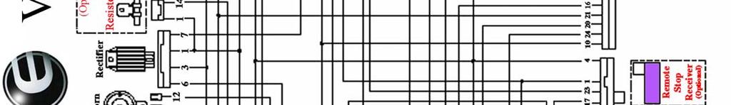
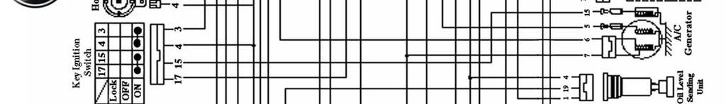
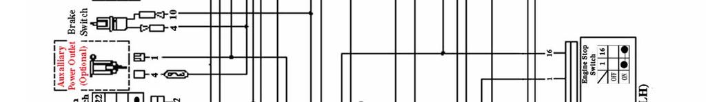
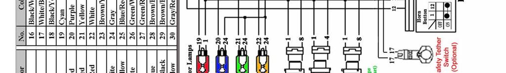
30 Wire diagram Viper 70M (RX4-70M) Page 29


31 Wire diagram RX4-90R Page 30
32 Warranty ETON AMERICA, LLC. LIMITED VEHICLE WARRANTY ETON America warrants all new ETON vehicles sold by authorized Eton Dealers to be free from defects in materials and workmanship, subject to the following exclusions and limitations. New vehicles sold by an authorized dealer to original retail consumers are covered by this policy for a period of six (6) months from the date of delivery. There is no mileage limitation. Vehicles used in rental service or for certain commercial purposes are specifically excluded from this policy. (Check with your dealer for warranty application.) Items and conditions that are specifically excluded from this warranty program are; 1. Damage caused by accidents, misuse, negligence, improper vehicle operation. 2. Any modification or alteration to any standard specifications or equipment. 3. Any repairs made by an unauthorized dealer or service firm. 4. Use of non-eton genuine parts for repairs or alteration to standard specifications. 5. Damage caused by failure to perform factory scheduled service maintenance. 6. Damage which occurs as a result of improper storage. 7. Damage caused by the use of improper fuel or lubricants, and/or failure to use proper oil/gas mixture on two stroke models. The following normal wear parts are specifically excluded from warranty coverage: 1. Rubber parts 2. Tires 3. Belts 4. Brake linings 5. Normal wear item 6. Brake parts 7. Cables 8. Filters 9. Spark plugs 10. Bulbs 11. Batteries 12. Sprockets 13. External springs 14. Seat and hand grips. Page 31
33 ETON AMERICA, LLC. LIMITED VEHICLE WARRANTY Scheduled maintenance service is the responsibility of the owner during and after the warranty period. In the event of a failure or required repair, the owner should take vehicle to an authorized dealer for repair without undue delay and within a maximum of thirty, (30), days of the occurrence of the problem. All eligible warranty repairs must be made at any authorized dealer s normal place of business. Any transportation costs, or other expenses which may occur in order to obtain warranty service, are the responsibility of the owner. All eligible repairs covered under this warranty will be paid to the servicing dealer only, by ETON America, and no additional payments shall be made for authorized warranty repairs. Dealer and/or ETON America are not responsible for loss of use, other damage or inconvenience due to warranty repairs. It is the customer/buyer s responsibility to review with the selling dealer the predelivery service schedule to assure machine is properly serviced prior to delivery acceptance. It is recommended that the buyer take a test ride to familiarize themselves with the machine and to make certain the unit is in proper operating condition. The dealer is responsible for checking and performing all items on the set-up and pre-delivery checklist prior to delivery to the customer. This warranty is valid at any authorized ETON Dealer in the United States only. In the event you experience any problem obtaining prompt service, contact ETON America, customer service department for assistance. Always consult first with your selling dealer and or service personnel for assistance with any service work or repairs. In the event you have a problem obtaining service send your name, address, and vehicle identification number to Eton America for assistance. The above stated policy is the only policy offered and backed by ETON America, and no other organization or individual is authorized to make or offer any different arrangements. Some states prohibit certain limitations or conditions or do not allow exclusions or limitations. You may be eligible for additional consideration, so check with your local dealer or appropriate state agency for assistance. Rights vary from state to state, and you may have other rights not offered in this warranty. ETON America warrants all new vehicles comply with applicable US regulations. Page 32
34 Owner s Notes: Page 33
35 ETON AMERICA, LLC. LIMITED VEHICLE WARRANTY ETON America warrants all new ETON vehicles sold by authorized ETON Dealers to be free from defects in materials and workmanship, subject to the following exclusions and limitations. New vehicles sold by an authorized dealer to original retail consumers are covered by this policy for a period of six (6) months from the date of delivery. There is no mileage limitation. This warranty is given to the original retail purchaser and is non-transferrable. Vehicles used in rental service or for certain commercial purposes are specifically excluded from this policy. (Check with your dealer for warranty application.) Items and conditions that are specifically excluded from this warranty program are; 8. Damage caused by accidents, misuse, negligence, improper vehicle operation, 9. Any modification or alteration to any standard specifications or equipment. 10. Any repairs made by an unauthorized dealer or service firm, 11. Use of non-eton genuine parts for repairs or alteration to standard specifications. 12. Damage caused by failure to perform factory scheduled service-maintenance. 13. Damage which occurs as a result of improper storage. 14. Damage caused by the use of improper fuel or lubricants, and/or failure to use proper oil/gas mixture on two stroke models. The following normal wear parts are specifically excluded from warranty coverage: 15. Rubber parts 16. Tires 17. Belts 18. Brake linings (after 30 days) 19. Normal wear item 20. Brake parts 21. Cables 22. Filters 23. Spark plugs 24. Bulbs 25. Batteries (after 30 days) 26. Sprockets 27. External springs 28. Seat and hand grips. Scheduled maintenance service is the responsibility of the owner during and after the warranty period. In the event of a failure or required repair, the owner should take vehicle to an authorized dealer for repair without undue delay and within a maximum of thirty, (30), days of the occurrence of the problem. All eligible warranty repairs must be made at any authorized dealer s normal place of business. Any transportation costs, or other expenses which may occur in order to obtain warranty service, are the responsibility of the owner. All eligible repairs covered under this warranty will be paid to the servicing dealer only, by ETON America, and no additional payments shall be made for authorized warranty repairs. Dealer and/or ETON America are not responsible for loss of use, other damage or inconvenience due to warranty repairs. It is the customer/buyer s responsibility to review with the selling dealer the pre-delivery service schedule to assure machine is properly serviced prior to delivery acceptance. It is recommended that the buyer take a test ride to familiarize themselves with the machine and to make certain the unit is in proper operating condition. The dealer is responsible for checking and performing all items on the set-up and pre-delivery checklist prior to delivery to the customer. This warranty is valid at any authorized ETON Dealer in the United States only. In the event you experience any problem obtaining prompt service, contact ETON America, customer service department for assistance. Always consult first with your selling dealer and or service personnel for assistance with any service work or repairs. In the event you have a problem obtaining service send your name, address, and vehicle identification number to Eton America for assistance. The above stated policy is the only policy offered and backed by ETON America, and no other organization or individual is authorized to make or offer any different arrangements. Some states prohibit certain limitations or conditions or do not allow exclusions or limitations. You may be eligible for additional consideration, so check with your local dealer or appropriate state agency for assistance. Rights vary from state to state, and you may have other rights not offered in this warranty. ETON America warrants all new vehicles comply with applicable US regulations. Page 34
 accident, (ii) misuse or neglect, (iii) lack of reasonable and proper")
36 ETON AMERICA, LLC. LIMITED VEHICLE WARRANTY LIMITATIONS. This Limited Vehicle Warranty shall not cover any of the following: Repairs or replacement required as a result of (i) accident, (ii) misuse or neglect, (iii) lack of reasonable and proper maintenance, (iv) repairs improperly performed or replacement improperly installed, (v) use of replacement parts or accessories not conforming to ETON America LLC specifications which adversely affect 1) performance and/or durability, (vi) alterations or modifications not recommended or approved in writing by ETON America LLC, and/or (vii) use in competitive racing or related events. 2) Replacement of parts and other services and adjustments required for routine maintenance. 3) Any vehicle on which odometer mileage has been changed so that the actual mileage cannot be determined. LIMITED LIABILITY. The liability of ETON America LLC under this Limited Vehicle Warranty is limited solely to the remedying of the defects in the materials or workmanship by any authorized ETON America LLC vehicle dealer at its place of business during customary business hours. Please refer to ETON America LLC website: This warranty does not cover inconvenience or loss of use of the Scooter/moped vehicle, or transportation of the Scooter/moped vehicle to or from the ETON America LLC authorized dealer. ETON America LLC SHALL NOT BE LIABLE FOR AANY OTHER EXPENSE, LOSS OR DAMMAGE, WHETHER DIRECT, INCIDENTAL, CONSEQUENTIAL OR EXEMPLARY ARRISING IN CONNECTION WITH THE SALE OR USE OF OR INABILITY TO USE THE ETON America LLC SCOOTER/MOPED VEHICLE FOR ANY PURPOSE, SOME STATES DO NOT ALLOW THE EXCLUTION OR LIMITATION OF ANY INCEDENTAL OR CONSEQUENTAL DAMAGES, SO THE ABOVE LIMITATION OR EXCLUSION MAY NOT APPLY TO YOU. Page 35
37 ETON America LLC ATV LIMITED WARRANTY FEDERAL EMMISSION CONTROL SYSTEMS ETON America LLC warrants each new Scooter/moped vehicle that includes as standard equipment a taillight and a stoplight; a) Is designed, built and equipped so as to conform at the time of initial retail purchase with all applicable regulation of the United States Environmental Protection Agency ( US EPA ) and: b) Is free from defects in material and workmanship which would cause such Scooter/moped vehicle to fail to conform with applicable regulations of the US EPA, for a time period of two and a half (2.5) years and, depending on the engine displacement: This warranty period shall begin on the date the Scooter/moped vehicle is delivered to the initial retail purchaser, or on the date the Scooter/moped vehicle is placed in service as demonstrator, rental, lease, or company Scooter/moped vehicle prior to retail sale. 4) COVERAGE. Warranty defects shall be remedied during customary business hours at any authorized ETON America LLC Scooter/moped dealer located within the United States in compliance with the Clean Air Act and applicable regulation of the US EPA. Any part or parts replaced under this warranty shall become the property of ETON America LLC. 5) OWNERS OBLIGATION. The following obligations must be fulfilled by the owner to maintain the validity of the ETON America LLC Emission Control System Warranty: a) Owner must deliver the Scooter/moped vehicle to an authorized ETON America LLC Scooter/moped vehicle dealer or equally qualified service facility for inspection, maintenance service and adjustments according to the Periodic maintenance chart provided as part of, or supplemental to the Owner s manual. Optionally, the Owner may perform this maintenance only if it is within the scope o f the Owner s technical and practical ability, keeping in mind some maintenance operations may require special tools or technical expertise beyond the scope of the average Owner. In any event, the inspection, maintenance and adjustments are to be performed at the Owner s expense. b) Owner must present a copy of the proof of initial retail purchase date, issued at the time of purchase to an authorized ETON America LLC Scooter/moped vehicle dealer at the time warranty repairs are performed on the Scooter/moped vehicle. You may also be required to show that you have performed the required maintenance which is related to the alleged defect, so you should have detail receipts indicating that the required periodic maintenance has been performed in accordance with the periodic maintenance chart in your Owner s manual. 6) LIMITATIONS. This Emission Control System Warranty shall not cover any of the following: a) Repairs or replacement required as a result of (i) accident, (ii) misuse or neglect, (iii) lack of reasonable and proper maintenance, (iv) repairs improperly performed or replacement improperly installed, (v) use of replacement parts or accessories not conforming to ETON America LLC specifications which adversely affect performance and/or durability, (vi) alterations or modifications not recommended or approved in writing by ETON America LLC, and/or (vii) use in competitive racing or related events. b) Replacement of parts and other services and adjustments required for routine maintenance. c) Any Scooter/moped vehicle on which odometer mileage has been changed so that the actual mileage cannot be determined. 7) LIMITED LIABILITY. a) The liability of ETON America LLC under this Emission Control System Warranty is limited solely to the remedying of the defects in the materials or workmanship by any authorized ETON America LLC Scooter/moped vehicle dealer at its place of business during customary business hours. Please refer to ETON America LLC website: This warranty does not cover inconvenience or loss of use of the Scooter/moped vehicle, or transportation of the Scooter/moped vehicle to or from the ETON America LLC authorized dealer. ETON America LLC SHALL NOT BE LIABLE FOR AANY OTHER EXPENSE, LOSS OR DAMMAGE, WHETHER DIRECT, INCIDENTAL, CONSEQUENTIAL OR EXEMPLARY ARRISING IN CONNECTION WITH THE SALE OR USE OF OR INABILITY TO USE THE ETON America LLC SCOOTER/MOPED VEHICLE FOR ANY PURPOSE, SOME STATES DO NOT ALLOW THE EXCLUTION OR LIMITATION OF ANY INCEDENTAL OR CONSEQUENTAL DAMAGES, SO THE ABOVE LIMITATION OR EXCLUSION MAY NOT APPLY TO YOU. Page 36


38 Page 37
E-TON VIPER OWNER S MANUAL. Viper 50M, Viper 70, Viper 90 and Viper 90R
 E-TON VIPER OWNER S MANUAL Viper 50M, Viper 70, Viper 90 and Viper 90R Important Notices READ and UNDERSTAND this owner s manual Both the operator and the adult supervisor should completely read and understand
Important Notices. Age Recommendations by model size ATV Model Size ETON Models Minimum Age Weight Capacity
 E-TON CXL-150 Important Notices READ and UNDERSTAND this owner s manual Both the operator and the adult supervisor should completely read and understand this owner s manual before operating this vehicle.
NOTES FOR SAFETY OPERATOR-ONLY.
 NOTES FOR SAFETY Both the parents and their child must fully understand everything in this manual before riding. This vehicle is for OPERATOR-ONLY. This vehicle is only designed for operation on level,
E-TON. Beamer Scooter OWNER S MANUAL
 E-TON Beamer Scooter OWNER S MANUAL Dear Customer, Thank you for choosing the ETON Beamer. This scooter was made in accordance with the international QS9000 standards and the directives of the European
(for Viper (for Yukon
 TABLE OF CONTENTS YOUR RESPONSIBILITIES CONTROL FEATURES ENGINE CONTROLS Start Button THROTTLE LEVER BRAKE CONTROLS (for Viper ST) (for Yukon ST) 3 4 5 5 6 7 7 7 8 FUEL SYSTEM Fuel Tank Fuel Valve Inline
E-TON. Beamer & Beamer Matrix Scooters OWNER S MANUAL. Model years 2004 through 2008
 E-TON Beamer & Beamer Matrix Scooters OWNER S MANUAL Model years 2004 through 2008 Rev 3.01 8-0904 Dear Customer, Thank you for choosing the ETON Beamer. This scooter was made in accordance with the international
w.get2itparts.com ETON America
 ETON America 50-70-90cc SERVICE MANUAL Covering Models: Viper 50 (RXL-50) Viper 50M (RXL-50M) Viper 70 (RXL-70) Viper 90 (RXL-90) Viper 90R (RXL-90R) om VIPER SERIES (RXL-50, 50M, 70, 90, 90R) August 2004
ATV-50/90/100 I/II/V OWNER S MANUAL
 1 ATV-50/90/100 I/II/V OWNER S MANUAL FOREWORD May we, the manufacturer, take this opportunity to thank you for choosing our ATV to serve you. This Owner s Manual is prepared for you the details as to
To be completed by Authorized ETON Dealership. Buyers Agreement Checklist Scooters
 To be completed by Authorized ETON Dealership Buyers Agreement Checklist Scooters As members of the Motor Vehicle industry, our staff and management would like to thank you for your purchase of an E-TON
May we, the manufacturer, take this opportunity to thank you for choosing our ATV to serve you.
 FOREWORD May we, the manufacturer, take this opportunity to thank you for choosing our ATV to serve you. This Owner s Manual is prepared for you the details as to operate and maintenance necessarily to
ATV-320 R OWNER S MANUAL
 ATV-320 R OWNER S MANUAL FOREWORD May we, the manufacturer, take this opportunity to thank you for choosing our ATV to serve you. This Owner s Manual is prepared for you to properly operate in safety.
Table of Contents. Safety symbols... 3 Assembly 6. Operation Maintenance Troubleshooting 11. Storage. 12. Notes. 13
 Table of Contents Safety symbols... 3 Assembly 6 Operation... 8 Maintenance... 10 Troubleshooting 11 Storage. 12 Notes. 13 2 Safety Information Attention; this machine can be dangerous! All operators should
ATV-320 S/U ATV-320SD S/U OWNER S MANUAL V
 ATV-320 S/U ATV-320SD S/U OWNER S MANUAL V1.0 2014.03.01 0 FOREWORD May we, the manufacturer, take this opportunity to thank you for choosing our ATV to serve you. This Owner s Manual is prepared for you
INSPECTION/ADJUSTMENT
 3 3 INSPECTION/ADJUSTMENT SERVICE INFORMATION----------------------------------------------------------------------- 3-1 MAINTENANCE SCHEDULE-------------------------------------------------------------------
Operating and Assembly Manual
 Model 1080 Operating and Assembly Manual Midwest Equipment Manufacturing, Inc. 5225 Serum Plant Road Thorntown, IN 46071 08-02-16 SAFETY RULES Remember, any power equipment can cause injury if operated
QUICK REFERENCE GUIDE
 QUICK REFERENCE GUIDE www.familygokarts.com CUSTOMER SERVICE Customer Service is our top prority and checking these simple steps will help us in better serving you needs. Please remember that although
RASER R1/ RASER FX OWNER'S MANUAL
 RASER R1/ RASER FX OWNER'S MANUAL IMPORTANT NOTES FOR SAFE OPERATION FAILURE TO FOLLOW THE INSTRUCTIONS CONTAINED HEREIN MAY RESULT IN DAMAGE TO YOUR SCOOTER, DECREASE ENGINE LIFE, CAUSE INJURY TO YOURSELF
OWNERS MANUAL. Two Stroke Dirt Bike. Distributed by SSR Motorsports. Address: Alondra Blvd, Norwalk CA
 OWNERS MANUAL Two Stroke Dirt Bike Distributed by SSR Motorsports Address: 12825 Alondra Blvd, Norwalk CA 90650 www.ssrmotorsports.com Please note that this is a general manual. The model of the vehicle
3. INSPECTION/ADJUSTMENT
 3 3 INSPECTION/ADJUSTMENT SERVICE INFORMATION -------------------------------------------- 3-1 MAINTENANCE SCHEDULE ---------------------------------------- 3-2 FUEL LINE/FUEL FILTER -------------------------------------------
Owner s Manual Read and keep this manual. Patents World Wide
 Owner s Manual Read and keep this manual. Patents World Wide S & S Industries, Inc., Sarasota, FL, USA www.trail-gator.com Copyright 2006 All Rights Reserved The following manual is provided to assist
KING CANADA 950W PORTABLE GENERATOR MODEL: KCG-951G INSTRUCTION MANUAL COPYRIGHT 2011 ALL RIGHTS RESERVED BY KING CANADA TOOLS INC.
 KING CANADA 950W PORTABLE GENERATOR MODEL: KCG-951G INSTRUCTION MANUAL COPYRIGHT 2011 ALL RIGHTS RESERVED BY KING CANADA TOOLS INC. WARRANTY & SERVICE INFORMATION 1-YEAR LIMITED WARRANTY FOR THIS 950W
Single and Double Head Powered Screed. Screed King. User Manual. SCR-UM EN-04 (December 2018)
") Single and Double Head Powered Screed Screed King SCR-UM-00364-EN-04 () User Manual Single and Double Head Powered Screed, Screed King CONTENTS Scope of This Manual.............................................
Single and Double Head Powered Screed Screed King SCR-UM-00364-EN-04 () User Manual Single and Double Head Powered Screed, Screed King CONTENTS Scope of This Manual.............................................
RedGum GP160 Splitter. Owner s Manual
 RedGum GP160 Splitter Owner s Manual Product Description & Intended Purpose: This Log Splitter / Wood Splitter is an outdoor product that splits wood logs for use as fuel in a fireplace or a woodstove.
AIR-COOLED DIESEL GENERATOR OWNERʼS MANUAL. This manual contains important safety information. TDG2500E TDGW7000E TDG7000SE TDG4500E
 AIR-COOLED DIESEL GENERATOR OWNERʼS MANUAL This manual contains important safety information. TDG2500E TDGW7000E TDG7000SE TDG4500E TDG8000-3 TDG7000SE-3 TDG7000E TDG8000E TDGW7000SE TDG7000E3 TDGW8000E
PERIODIC MAINTENANCE
 PERIODIC MAINTENANCE CONTENTS PERIODIC MAINTENANCE SCHEDULE 2 1 MAINTENANCE PROCEDURES 2 3 2 BATTERY 2 3 CYLINDER HEAD NUTS AND EXHAUST PIPE NUTS 2 4 CYLINDER HEAD AND CYLINDER 2 4 SPARK PLUG 2 4 FUEL
3. INSPECTION/ADJUSTMENT
 3 SERVICE INFORMATION...3-0 FINAL REDUCTION GEAR OIL...3-7 MAINTENANCE SCHEDULE...3-2 DRIVE BELT...3-7 FUEL FILTER...3-3 BRAKE SHOE...3-8 THROTTLE OPERATION...3-3 BRAKE ADJUSTING NUT...3-8 AIR CLEANER...3-4
3. INSPECTION/ADJUSTMENT
 SERVICE INFORMATION...3-0 FINAL REDUCTION GEAR OIL...3-7 MAINTENANCE SCHEDULE...3-2 DRIVE BELT...3-7 FUEL FILTER...3-3 BRAKE SHOE...3-8 THROTTLE OPERATION...3-3 BRAKE ADJUSTING NUT...3-8 AIR CLEANER...3-4
North Dakota State University Grounds Maintenance Equipment
 North Dakota State University Grounds Maintenance Equipment I. Introduction Grounds maintenance equipment is an important part of the work activities on NDSU campus. They can make grounds maintenance jobs
AG-HA-2500N GASOLINE GENERATOR
 AG-HA-2500N GASOLINE GENERATOR OWNER S MANUAL BEFORE OPERATING THIS EQUIPMENT PLEASE READ THESE INSTRUCTIONS CAREFULLY (I)WARNING 1. Read the operator s instruction manual. 2. Attention! Exhaust gases
1200W INVERTER GENERATOR
 1200W INVERTER GENERATOR MODEL NO: IG1200 PART NO: 8877070 OPERATION & MAINTENANCE INSTRUCTIONS LS0117 INTRODUCTION Thank you for purchasing this CLARKE 1200W Inverter Generator. Before attempting to use
Product Handbook FOR THE BLADEZ XTR Lite ELECTRIC POWER BOARD
 Portable Electric Power Board Product Handbook FOR THE BLADEZ XTR Lite ELECTRIC POWER BOARD PLEASE BE SAFE WHEN RIDING... ALWAYS WEAR A HELMET AND OBEY ALL LAWS! Page 1 IMPORTANT PLEASE READ THIS BEFORE
Product Handbook. Electric Power Board. Powered Personal Transportation. FOR THE BLADEZ XTR Lite 250 ELECTRIC POWER BOARD
 ` Powered Personal Transportation Electric Power Board Product Handbook FOR THE BLADEZ XTR Lite 250 ELECTRIC POWER BOARD Model: PB-SM805-S PLEASE BE SAFE WHEN RIDING... ALWAYS WEAR A HELMET AND OBEY ALL
Product Handbook GAS POWERBOARD. Powered Personal Transportation GAS POWERBOARD PLEASE BE SAFE WHEN RIDING FOR THE BLADEZ MOBY 35/40
 Powered Personal Transportation GAS POWERBOARD ` Product Handbook FOR THE BLADEZ MOBY 35/40 GAS POWERBOARD Models: PB-SE802 PB-SE803 PB-SE1802 PB-SE1803 PLEASE BE SAFE WHEN RIDING ALWAYS WEAR A HELMET
Gasoline Inverter Generator
 user manual Gasoline Inverter Generator table of contents Preface Introduction... Safety Information Exhaust fumes are poisonous... Fuel is highly flammable and poisonous... Engine and muffler may be hot...
GENERATOR MODEL NO: FG3005 OPERATION & MAINTENANCE INSTRUCTIONS PART NO: LS0413
 GENERATOR MODEL NO: FG3005 PART NO: 8857707 OPERATION & MAINTENANCE INSTRUCTIONS LS0413 INTRODUCTION Thank you for purchasing this CLARKE Generator. Before attempting to use this product, please read this
1.CONTENTS 1. Contents Control location Before riding Safe riding Driving Use genuine spare parts Use
 1.CONTENTS 1. Contents... 1 2. Control location... 3 3. Before riding... 4 4. Safe riding... 4 5. Driving... 5 6. Use genuine spare parts... 5 7. Use of each component... 6 Gauges... 6 Operation of ignition
Table of Contents. Safety Assembly Pre-operation / Starting. 7. Operation.. 8. Maintenance. 9. Storage 10
 Table of Contents Safety... 3 Assembly... 6 Pre-operation / Starting. 7 Operation.. 8 Maintenance. 9 Storage 10 Parts drawings..11 Parts list by number..12 Notes.13 2 Safety Information Attention; this
I: INSPECT AND CLEAN, ADJUST, LUBRICATE OR REPLACE IF NECESSARY C: CLEAN A: ADJUST R: REPLACE L: LUBRICATE I: INSPECTION D: DIAGNOSE
 2. Periodic Maintenance > Periodic Maintenance Chart XCITING 400i Maintenance Schedule Perform the pre-ride inspection (Owner's Manual) at each scheduled maintenance period. This interval should be judged
Owner s Manual. Mortar / Plaster Mixer. Models M785 M1000 M1200
 Owner s Manual Mortar / Plaster Mixer Models M785 M1000 M1200 Tiger Equipment LLC. 15 Byrd Lane Rocky Mount, VA 24151 Tel: 540-489-7777 Fax: 540-489-7778 www.tigerequip.com 1. PREFACE This manual contains
MODEL HD99 HYDRAULIC ONE MAN TOWABLE EARTHDRILL
 DO NOT THROW AWAY IMPORTANT MANUAL MODEL HD99 HYDRAULIC ONE MAN TOWABLE EARTHDRILL Operators Manual GROUND HOG, INC. P.O.BOX 290 San Bernardino, CA. 92402 Phone (909) 478-5700 Fax (909) 478-5710 E-mail:
1100W PORTABLE GENERATOR
 1100W PORTABLE GENERATOR MODEL NO: G1200 PART NO: 8010110 OPERATION & MAINTENANCE INSTRUCTIONS LS0312 INTRODUCTION Thank you for purchasing this CLARKE 1100W Portable Generator. Before attempting to use
MODEL 565CKG Operating and Assembly Manual Midwest Equipment Manufacturing, Inc Serum Plant Road Thorntown, IN 46071
 MODEL 565CKG Operating and Assembly Manual Midwest Equipment Manufacturing, Inc. 5225 Serum Plant Road Thorntown, IN 46071 11-20-14 SAFETY RULES Remember, any power equipment can cause injury if operated
Air-Operated Waste Oil Drainer
 Air-Operated Waste Oil Drainer 20-Gallon Tank Owner s Manual WARNING: Read carefully and understand all ASSEMBLY AND OPERATION INSTRUCTIONS before operating. Failure to follow the safety rules and other
PLEASE BE SAFE WHEN RIDING... ALWAYS WEAR A HELMET AND OBEY ALL LAWS!
 Powered Personal Transportation Electric Power Board Product Handbook FOR THE BLADEZ XTR Street ELECTRIC POWER BOARD Model: PB-SM1806 PLEASE BE SAFE WHEN RIDING... ALWAYS WEAR A HELMET AND OBEY ALL LAWS!
FUZION V1000 LITHIUM POWERED owner s manual. 500 W of Power 18 MPH Full Suspension Disc Brake
 FUZION V1000 LITHIUM POWERED 500 W of Power 18 MPH Full Suspension Disc Brake Maximum Weight: 220 lbs (100 kilograms) Manual Version 1A-2015 CONTENTS WELCOME / Before You Start page 1 Components & Parts
OWNERS MANUAL. KXDMOTO.de. KXDMOTO.de. Content. Original instructions. Manufacturer: Zhejiang Kingroma Industrial & Trading CO.,LTD.
 OWNERS MANUAL Manufacturer: Zhejiang Kingroma Industrial & Trading CO.,LTD. Address:NO.1 Baihe Road, Baihuashan Industrial Area, Wuyi, Zhejiang China Please note that this is a general manual. So, the
ETON America PARTS CATALOG
 ETON America PARTS CATALOG Matrix 50 Parts and drawing are subject to change without notice. ETON America reserves the right to substitute parts that have engineering changes that can alter the appearance
PE51 HURLEY 3 STATION METAL SWING SET OWNER'S MANUAL
 PE51 HURLEY 3 STATION METAL SWING SET OWNER'S MANUAL WARNING! The disassembled product may contain small parts which pose a choking hazard to children under 3. IMPORTANT: This product may contain sharp
Owner s/operator s Manual
 Water Pump MP2533E2 Owner s/operator s Manual Completely read and understand this manual before using this product. Foreword This Owner s/ Operator s Manual is designed to familiarize the operator with
Follow the Age Recommendation Adult Supervision should be present for all people under the age of 18.
 Your Kart will provide you with many years of service and pleasure. Providing you take responsibility for your own safety and understand the challenges you can meet while driving. There is much that you
Operation Manual. 10 Mini-Cultivator MODEL #
 10 Mini-Cultivator MODEL # 103350 Operation Manual This safety alert symbol identifies important safety messages in this manual. Failure to follow this important safety information may result in serious
DYNAPAC CONCRETE EQUIPMENT RAMIRENT. BG70 Power Floats INSTRUCTIONS & SPARE PARTS CATALOGUE BG70 - IS ENG
 DYNAPAC CONCRETE EQUIPMENT INSTRUCTIONS & SPARE PARTS CATALOGUE BG70 Power Floats BG70 - IS - 10682 - ENG SAFETY INSTRUCTIONS - MACHINES SUBMITTED : Powered with : Electric, Pneumatic, Petrol or Diesel
Instruction Model 18537
 Instruction 738-556 Model 18537 LIMITED WARRANTY H. D. Hudson Manufacturing Company warrants to the original purchaser only that this product will continue to function as intended if used in accordance
Log Splitter. Owner/Operator Manual. Models HCWP1-26
 Log Splitter Owner/Operator Manual Models HCWP1-26 SAFETY..........................2 SAFETY WARNING SYMBOL.........3 SAFETY RULES.................. 4-5 SPECIFICATIONS................. 6 CONTROLS AND FEATURES.......
CHASSIS CONTENTS EXTERIOR PARTS 6-1 FRONT WHEEL 6-2 FRONT BRAKE 6-6 HANDLEBARS 6-12 REAR WHEEL 6-30 REAR BRAKE 6-34 REAR SHOCK ABSORBER 6-36
 CHASSIS CONTENTS EXTERIOR PARTS 6-1 FRONT WHEEL 6-2 FRONT BRAKE 6-6 HANDLEBARS 6-12 FRONT FORK ( ) 6-14 FRONT FORK ( ) 6-20 STEERING 6-27 REAR WHEEL 6-30 REAR BRAKE 6-34 REAR SHOCK ABSORBER 6-36 6 SWING
ETON America PARTS CATALOG
 ETON America PARTS CATALOG Parts and drawing are subject to change without notice. ETON America reserves the right to substitute parts that have engineering changes that can alter the appearance of the
Click Here for Printable PDF File. CHAPTER 3 - BASIC INFORMATION for PERFORMING HYDRAULIC SYSTEM MAINTENANCE
 HWH Online Technical School Lesson 1: Introduction to Hydraulics Chapter 3 - "BASIC INFORMATION for PERFORMING HYDRAULIC SYSTEM MAINTENANCE" (Filename: ML57000-012-CH3.DOC Revised: 22APR16) Click Here
HOW - TO EMISSION CONTROL BASICS EMISSION CONTROL BASICS
 HOW - TO EMISSION CONTROL BASICS EMISSION CONTROL BASICS Tool And Material Checklist Bore Brush Thermometer Portable Vacuum Pump Screwdriver Combination Wrench Set 3/8 Drive Socket Set Tachometer Rag Service
MODELS 1324 & 1624 & 1824
 THE MODELS 1324 & 1624 & 1824 HYDRAULIC TRENCHERS CONGRATULATIONS! You are now the proud owner of a BARRETO trencher. Please take a moment of your time to look over the following information. Familiarize
WARNING - BEFORE YOU DRIVE
 See back cover for a pre-ride checklist section 3 operation WARNING - BEFORE YOU DRIVE 1. Always perform a pre-ride inspection of the vehicle using the checklist provided on the back cover of this manual.
Table of Contents. Technical Information Warning Statement
 Table of Contents Technical Information-----------------------------------1 Warning Statement--------------------------------------2 Read Before Riding-------------------------------------3 List of Parts-----------------------------------------------4
ATV TRACK KIT. Operator s Manual Installation Instructions Service Instructions Replacement Parts List. Effective Date: October, 2012
 p/n 2258-642 ATV TRACK KIT Operator s Manual Installation Instructions Service Instructions Replacement Parts List Track Assembly Kits (p/n 1436-204) Mounting Assembly Kits (p/n 1436-205) 1436-815) Effective
CHASSIS CONTENTS EXTERIOR PARTS 6-1 FRAME COVER 6-2 REAR FRAME COVER 6-4 FRONT WHEEL 6-6 FRONT BRAKE 6-10 HANDLEBARS 6-17 FRONT FORK 6-19
 CHASSIS CONTENTS EXTERIOR PARTS 6- FRAME COVER 6- REAR FRAME COVER 6-4 FRONT WHEEL 6-6 FRONT BRAKE 6-0 HANDLEBARS 6-7 FRONT FORK 6-9 STEERING 6-6 REAR WHEEL 6-3 REAR BRAKE 6-39 6 REAR SHOCK ABSORBER 6-43
Operation Manual. 21 Inch Self-Propelled Lawn Mower MODEL #
 21 Inch Self-Propelled Lawn Mower MODEL # 106461 Operation Manual This safety alert symbol identifies important safety messages in this manual. Failure to follow this important safety information may result
Water pump Owner's Manual
 Water pump Owner's Manual Safety Precautions I. General Safeguards Please read this operation manual to have a thorough understanding of the content there before use the product. Failure to do so may lead
PORTABLE TRASH PUMPS MDP200
 PORTABLE TRASH PUMPS MDP200 OPERATING & PARTS MANUAL INTRODUCTION This manual provides information and procedures to safely operate and maintain the engine and pump. For your own safety and protection
5.5KVA GENERATOR MODEL NO: PG6500DVES OPERATION & MAINTENANCE INSTRUCTIONS PART NO: LS0616
 5.5KVA GENERATOR MODEL NO: PG6500DVES PART NO: 8857810 OPERATION & MAINTENANCE INSTRUCTIONS LS0616 INTRODUCTION Thank you for purchasing this CLARKE 5.5KVA Generator. Before attempting to use this product,
GENERATOR MODEL NO: FG2500 OPERATION & MAINTENANCE INSTRUCTIONS PART NO: LS0114
 GENERATOR MODEL NO: FG2500 PART NO: 8857727 OPERATION & MAINTENANCE INSTRUCTIONS LS0114 INTRODUCTION Thank you for purchasing this CLARKE Generator. Before attempting to use this product, please read this
ETON America PARTS CATALOG. Matrix R4-150
 ETON America PARTS CATALOG w.getitparts.com Matrix R4-50 www.getitparts.com Parts and drawing are subject to change without notice. ETON America reserves the right to substitute parts that have engineering
3. INSPECTION/ADJUSTMENT
 3 INSPECTION/ADJUSTMENT SERVICE INFORMATION------------------------------------------------ 3-1 MAINTENANCE SCHEDULE-------------------------------------------- 3-3 FUEL LINE/THROTTLE OPERATION---------------------------------
Owner s Manual for 16 Slider
 Owner s Manual for 16 Slider This manual contains important safety, assembly, operation and maintenance information. Please read and fully understand this manual before operation. Save this manual for
3-Pt. Quick Hitch. Owner s Manual
 3-Pt. Quick Hitch Owner s Manual WARNING: Read carefully and understand all ASSEMBLY AND OPERATION INSTRUCTIONS before operating. Failure to follow the safety rules and other basic safety precautions may
CHASSIS CONTENTS EXTERIOR PARTS 7-1 FRONT WHEEL 7-2 FRONT BRAKE 7-6 HANDLEBARS 7-13 FRONT FORK 7-15 STEERING 7-23 REAR WHEEL 7-26 REAR BRAKE 7-30
 CHASSIS CONTENTS EXTERIOR PARTS 7- FRONT WHEEL 7-2 FRONT BRAKE 7-6 HANDLEBARS 7-3 FRONT FORK 7-5 STEERING 7-23 REAR WHEEL 7-26 REAR BRAKE 7-30 REAR SHOCK ABSORBER 7-32 SWING ARM 7-33 7 7- CHASSIS EXTERIOR
Operating and Assembly Manual
 Model 470-/H/PRO/IC Operating and Assembly Manual Midwest Equipment Manufacturing, Inc. 5225 Serum Plant Road Thorntown, IN 46071 11-11-11 SAFETY RULES Remember, any power equipment can cause injury if
Model 858-RH. Operating and Assembly Manual. Palmor Products Inc Serum Plant Road Thorntown, IN 46071
 Model 5-RH Operating and Assembly Manual Palmor Products Inc. 55 Serum Plant Road Thorntown, IN 6071 3/31/015 SAFETY RULES Remember, any power equipment can cause injury if operated improperly or if the
Panther Rhino Tear-Off Machine Instruction Manual
 WARNING! The Panther Rhino Tear-Off Machine is manufactured to be used for the sole purpose of tearing off roofing systems on flat, level roofs for the re-roofing process. Serious injury or death may result
IMPORTANT INFORMATION
 Table of Contents IMPORTANT INFORMATION Section 1B - Maintenance MAINTENANCE 1 B Specifications........................... 1B-1 Special Tools........................... 1B-2 Mercury/Quicksilver Lubricants
1-1/2 DIAMETER WATER PUMP
 1-1/2 DIAMETER WATER PUMP 2.2HP/79.8cc Engine MODEL # 101099 Operation Manual This safety alert symbol identifies important safety messages in this manual. Failure to follow this important safety information
DO NOT RETURN TO STORE! ROSSO MOTORS ELECTRIC ATV OWNERS MANUAL. Read and understand this manual Prior to Riding!
 ROSSO MOTORS ELECTRIC ATV OWNERS MANUAL Read and understand this manual Prior to Riding! DO NOT RETURN TO STORE! Illustrations may not be exact appearance of actual product. Table of Contents General information:...3
Contents Safe Use Information... 3 Components and Key Features... 4 Using the Wildcat Safe-use Pre-Operation...
 1 Contents Safe Use Information... 3 Components and Key Features... 4 Using the Wildcat 3114... 8 Safe-use Pre-Operation... 8 Safe-use During Operation... 9 Starting the Wildcat 3114:... 9 Stopping the
BRAKE SYSTEM Return To Main Table of Contents
 BRAKE SYSTEM Return To Main Table of Contents GENERAL... 2 BRAKE PEDAL... 10 MASTER CYLINDER... 13 BRAKE BOOSTER... 16 BRAKE LINE... 18 PROPORTIONING VALVE... 19 FRONT DISC BRAKE... 20 REAR DRUM BRAKE...
3KVA DUAL VOLTAGE GENERATOR MODEL NO: PG3800DV
 3KVA DUAL VOLTAGE GENERATOR MODEL NO: PG3800DV PART NO: 8857815 OPERATION & MAINTENANCE INSTRUCTIONS LS1016 INTRODUCTION Thank you for purchasing this CLARKE 3KVA Dual Voltage Generator. Before attempting
ATV Log Arch and Holder
 ATV Log Arch and Holder Owner s Manual WARNING: Read carefully and understand all ASSEMBLY AND OPERATION INSTRUCTIONS before operating. Failure to follow the safety rules and other basic safety precautions
US Patent 0540, 400 Other Patents Pending. Read this manual completely before assembling and riding our PET PRO-FLEX 500. Always wear a Helmet!
 US Patent 0540, 400 Other Patents Pending Read this manual completely before assembling and riding our 500 Always wear a Helmet! Priority Electric Transportation, LLC. 1007 West College Ave. #293 Santa
MATRIX 50. Copyright ETON America, all rights reserved.
 MATRX 50 Dear Customer, Thank you for choosing the ETON Beamer. This scooter was made in accordance with the international QS9000 standards and the directives of the European parliament and council. t
Sherco Setup and Lubrication Guide
 Sherco Setup and This guide is designed to provide the Sherco owner with instructions on how to: Set up a new bike Clean and re-oil the air filter Change the transmission oil Change the fork oil Repack
HOFFMANN POWER PRODUCTS PARTS LIST 2014
 HOFFMANN POWER PRODUCTS PARTS LIST 2014 VIBRATORY PLATE COMPACTOR ALL PARTS ARE SUBJECT TO STANDARD HOFFMANN TERMS AND CONDITIONS OF SALE 2010 Replacement parts are not manufactured, sold or warranted
SAFETY AND OPERATION REQUIREMENTS CHART
 OPERATION, MAINTENANCE and SAFETY MANUAL MB16 and MTB16 Scoot-Crete Power Buggies IMPORTANT MACHINE SERVICE NOTES This manual covers the safety, operation and adjustment procedures for the Miller Scoot-Crete
User Manual of Bagibike Electric Bicycles
 User Manual of Bagibike Electric Bicycles Model: Bagibike B16. http://www.bagibike.com Page 1 FOREWORD The following operation manual is a guide to assist you. This manual is not a complete document on
WEBER CARBURETOR TROUBLESHOOTING GUIDE
 This guide is to help pinpoint problems by diagnosing engine symptoms associated with specific vehicle operating conditions. The chart will guide you step by step to help correct these problems. For successful
Garden Hose Reel with 3/4In. x 100Ft. Hose. Owner s Manual
 Garden Hose Reel with 3/4In. x 100Ft. Hose Owner s Manual WARNING: Read carefully and understand all ASSEMBLY AND OPERATION INSTRUCTIONS before operating. Failure to follow the safety rules and other basic
1000-lb Hydraulic Truck Crane
 1000-lb Hydraulic Truck Crane Owner s Manual WARNING: Read carefully and understand all ASSEMBLY AND OPERATION INSTRUCTIONS before operating. Failure to follow the safety rules and other basic safety precautions
Model 452-DIC/DH. Operating and Assembly Manual
 . Model 452-DIC/DH Operating and Assembly Manual Palmor Products Inc. 5225 Serum Plant Road Thorntown, IN 46071 02-14-12 SAFETY RULES Remember, any power equipment can cause injury if operated improperly
Parking brake Mechanical brake acting on rear wheels
 11 Brake System 11.1 General SPECIFICATIONS EJTC0010 Master cylinder Type Tandem type I.D. mm(in.) 20.64 mm (0.813 in.) Fluid level warning sensor Provided Brake booster Type Vacuum Boosting ratio 4.0
Voltmaster Centrifugal Trash Pumps
 Voltmaster Centrifugal Trash Pumps Model TSP2, TSP3 and TSP4 Owner s Manual February 2011 Table of Contents 1 Introduction............................ 1 1.1 Read before using..................... 1 1.2
720W PORTABLE GENERATOR
 720W PORTABLE GENERATOR MODEL NO: G720 PART NO: 8857800 OPERATION & MAINTENANCE INSTRUCTIONS LS0214 INTRODUCTION Thank you for purchasing this CLARKE 720W Portable Generator Before attempting to use this
MOTOX 70cc Assembly Manual
 MOTOX 70cc Assembly Manual Assembly Manual This manual should be considered a permanent part of the motorcycle and should remain if it is resold. This manual contains the latest product information available
PORTABLE TRASH PUMPS MTP200 MTP300 MTP400
 PORTABLE TRASH PUMPS MTP200 MTP300 MTP400 OPERATING & PARTS MANUAL INTRODUCTION This manual provides information and procedures to safely operate and maintain the engine and pump. For your own safety and
STIGA TORNADO 51 S 51 SE PRO 51 S
 STIGA TORNADO 51 S 51 SE PRO 51 S 8211-0225-09 SVENSKA S 1 2 3 1. 2. ADD FULL FULL ADD ADD FULL 0,15 l. 3. LS 45 4. XTE 60 3x 5. LS 45 6. XTE 60 STOP I H 7. 8. 2 S SVENSKA 9. 10. 11. 12. LS 45 0,75 mm
CONTENT. 3. Maintenance
 CONTENT Foreword -------------------------------------------------------------------------------------------- 1 1. The performance, technical parameters and structure of Go Kart--------------------------------------------2