BM-780 II. Service Manual V 2.1
|
|
|
- Gavin Cole
- 6 years ago
- Views:
Transcription


1 BM-780 II Service Manual V 2.1
2
3 Contents 1. GENERAL 1 2. TECHNICAL DESCRIPTION OF THE BM-780 II General Technical Data Properties and Handling Mechanical Design Circuit Description 8 3. DISASSEMBLING AND REASSEMBLING OF SUBASSEMBLIES AND PARTS Subassemblies and Mechanical Parts for BM-780 II Opening and Closing of the Case Exchange of Potentiometer for Power Setting (20) Exchange of Mains Switch (12) Exchange of Electrode Cable Sockets (23), (25) and (26) Exchange of Foot Switch Socket (28) Exchange of Membrane Keypad (3) Exchange of Mains Cord Socket (10) Exchange of Mains Transformer with Cable Tree (30) Exchange of RF Generator Printed Circuit Board (40) SERVICE ADJUSTMENTS AND CHECKS Visual Checks and Function Checks Adjustments at the RF Generator PCB Voltage setting in the Mains Circuit Safety Checks FAULT DIAGNOSIS BM-780 II 30
4 1. General The Sutter BM-780 II is an electrosurgery device at the recent standard of technology which meets the requirements of the market by its ease of handling, its up-to-date design and last but not least by its improved serviceability and reliability. The inherent safety functions to increase the patient's safety go beyond of what is demanded by law. This device is labelled with the CE mark which means the compliance with the requirements of the Medical Device Directive of the European Community. The manufacturer of this product is: Sutter Medizintechnik GmbH Tullastrasse Freiburg / Germany Telephone (*49) Telefax (*49) The BM-780 II is manufactured in Germany. In case of technical questions please contact your dealer or the numbers mentioned above. Repairs of this device shall only be performed by us or by dealers which are authorised by us. When returning a unit to the dealer or to Sutter Medizintechnik, the original package should be used if possible. The following documents are to be added: Name and address of the owner Type and serial number of the unit Any description of the fault Service concept The BM-780 II has a modular design. All parts can be disassembled and reassembled quickly. Electric and electronic subassemblies are connected by plugs, so no soldering will be required. In case of a fault of the main PCB, this part will be exchanged for an exchange price, because the repair of a SMD board at the client's site with common service tools is not possible in general. Repairing will be performed at the manufacturer's site if it makes sense economically. Because of that, this service manuals contains no wiring diagrams of the main PCB. The application of this service manual requires the knowledge of the operating instructions. V 2.1 1
5 Safety notes Inside the unit, there are parts which are in contact with the mains supply. Certain service procedures with the BM-780 II require the unit to be operated opened to perform measurements and alignments inside the unit. Then the general safety rules to avoid electric shock are to be taken into account. During operation, voltages of some 100 Volts of pulse voltage may occur in the secondary circuit and in the RF generator. Especially the big heatsink in the middle of the board may carry pulse voltages which may result in an electric shock. It is the destination of a RF electrosurgical unit to generate high voltages of high frequency for cutting and coagulation of body tissue. Although contact with such voltages will not result in an electric shock, it may result in severe burns. This can even happen on monopolar touch of the active electrode circuit since the unit is performed as a type BF unit, i. e. neutral electrode and ground potential are tied together for high frequency. Direct contact of the body to the active electrode circuit and ground may result in severe injuries. 2. Technical Description of the BM-780 II 2.1 General The BM-780 II is an all-purpose electrosurgical device with excellent performance. It is characterised by the following features: Easy handling by clear arrangement of the handling elements and the designation of them with catchy symbols. Power setting is enabled by a rotary knob. All connections of active electrodes and the Patient Plate (or Neutral Electrode) are at the front side. The connection for the foot switch is at the back side. Two current modes for cutting: There is a choice between smooth (pure) and hemostatic (blend) cutting. Activation by finger switch as well as by foot switch. Two current modes for coagulation: There is a choice between a coagulation current with higher power for contact coagulation and a coagulation current with high crest factor for spray coagulation. Activation by finger switch as well as by foot switch. One current mode for bipolar coagulation. Activation by foot switch. Optical and acoustic indication of RF activation by signal lamps of different colour and by a signal tone. Possibility to connect standard (single plated) as well as split Patient Plates. Includes a protective device to prevent an overdose fault due to failure of the unit according to IEC standard. No orifices or venting slots, no ventilator. Due to the high efficiency of the generator, there is only little power loss. The design of the front pad makes it easy to clean. 2 V 2.1
6 2.2 Technical Data Connection to mains V / V; 50/60 Hz settable by soldered jumpers inside the unit Power consumption without RF output: approx. 16 VA maximum RF output: approx. 180VA Protection class I MDD classification II b Leakage currents at low and high frequency: according to IEC and IEC Type of applied part BF; defibrillation proof Rated frequencies 460/920/1230 khz Modulation frequencies 58/77 khz RF output data Current mode Cut 1 Cut 2 Contact coagulation Spray coagulation Bipolar coagulation Output power max. 80 W ± max. 70 W ± max. 70 W ± max. 60 W ± max. 70 W ± V 2.1 3
7 Duty cycle of operation Intermitting INT 10 s / 30 s corresponds to 25 % duty cycle Mains fuses V: 2x T 1,6AH 250V (1,6 Ampere, slow blow) G 5x20mm V: 2x T 0,8AH 250V (0,8 Ampere, slow blow) G 5x20mm Loudness RF indicator: 55 db(a) Alarm indicator: 65 db(a) Weight approx. 5.2 kg Electromagnetic compatibility Keeps limits according to EN and IEC Meets requirements according to IEC 801 Dimensions Width 295 mm Height 136 mm Depth 280 mm This unit meets the requirements of directive 93 / 42 / EEC 4 V 2.1
8 Output characteristics BM 780 II Cut 1 BM 780 II Cut 2 RF power in Watts Resistance in Ohms RF power in Watts Resistance in Ohms BM 780 II Contact Coagulation BM 780 II Spray Coagulation RF power in Watts RF power in Watts Resistance in Ohms Resistance in Ohms BM 780 II Bipolar Coagulation RF power in Watts Resistance in Ohms V 2.1 5
9 2.3 Properties and Handling The BM-780 II features functions for three modes of application: Monopolar cutting: Serves to dissect biological tissue for surgical purposes. Monopolar coagulation: Serves to stop bleedings from dissected vessels which are unavoidable on cutting or to denaturate excess soft tissue so that it can be decomposed by the body postoperatively, e.g. for tissue volume reduction. Bipolar coagulation: Serves to perform a locally restricted coagulation by means of an instrument which incorporates both of the RF electrosurgery electrodes, e. g. a forceps. The unit is able to generate five different RF output currents: Smooth monopolar cutting (cut 1): In this operation mode, an unmodulated current, i. e. a current which is unaffected in its course of envelope, will be fed to the monopolar electrode and returns via the neutral electrode to the unit. Its properties are most similar to that of a scalpel cut. The effect of dissection is based on the formation of a separating layer which is formed by the steam evaporating from the tissue in which physical effects are valid which cause the dissection. Eschar forming monopolar cutting (cut 2): In this operation mode, a modulated current, i. e. a current with a course of envelope which is keyed periodically, will be fed to the monopolar electrode and returns via the neutral electrode to the unit. In contrast to the smooth current, this current does a simultaneous coagulation at the edges of the cut which inhibits bleeding from capillary vessels dissected by the cut. Monopolar contact coagulation: In this operation mode, a modulated current, i. e. a current with a course of envelope which is keyed periodically, will be fed to the monopolar electrode and returns via the neutral electrode to the unit. The effect of coagulation is based on the heating caused by the current passing through the tissue and the physiological effects associated with it. Monopolar Spray coagulation: In this operation mode, a strong modulated current, i. e. a current with an envelope which consists of a pulse train, will be fed to the monopolar electrode and returns via the neutral electrode to the unit. In contrast to the contact coagulation current, this current acts rather at the surface because the effect is less the current passing through the tissue but more the sparks occurring at the surface. Bipolar coagulation: The properties of this current are those of a current for contact coagulation. In contrast to the monopolar current, this current will not return via a neutral electrode but via a second electrode near the first electrode at the place of contact to the patient and symmetrical to it in most cases. 6 V 2.1
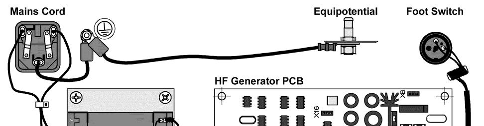
10 The modes are selected with keys at the front. The chosen current can be activated by means of a foot switch, in case of the monopolar currents also by means of a finger switch at the electrode handle. Activation will be indicated acoustically by a sound transducer inside the unit and optically by a yellow lamp for cutting or a blue lamp for monopolar or bipolar coagulation. Setting of the output power will be done by means of a rotary knob. The maximum settable power of the different operation modes is different (see item 2.2, Technical data). The rated maximum power will be fed to the rated load resistance. The mains switch is placed at the front side. A diode signal on the front panel indicates the unit to be in the switched-on state. The detachable mains cord is connected to the rear side. The BM-780 II incorporates a neutral electrode monitoring circuit which enables the connection and monitoring of single-plated as well as split Patient Plates to the unit. The terms Patient Plate and Neutral Electrode (abbreviated as NE ) are used synonymously throughout this document. In case of standard (single-plated) patient Plates, the twin-cored connection cable with the cores linked together at the electrode's side will be monitored in a current loop. Activation of monopolar current is possible only when the neutral electrode is connected to the unit. In case of Split Patient Plates, the patient shares the current loop. Activation of monopolar current is possible only on correct application of the electrode at the patient. A fault condition of the neutral electrode will be indicated by blinking of a red lamp above the neutral electrode socket. The bipolar operation mode is not affected by the neutral electrode monitoring Mechanical Design The unit is housed in a steel sheet case consisting of two parts. The bottom part with integrated front and rear side contains all subassemblies in receptacles or by means of fixed threaded bolts. In detail, the BM-780 II consists of the following parts: Case top Case bottom with receptacles and threaded bolts Membrane keypad with keys and lamps and connection cable Potentiometer for power setting with rotary knob Mains switch Socket carrier with NE socket, monopolar socket and bipolar socket, all with connection cable Foot switch socket with connection cable Mains cord socket with mains fuse cartridges Mains transformer with cable tree RF generator PCB Details of construction are visible in the schematics in item 3. V 2.1 7
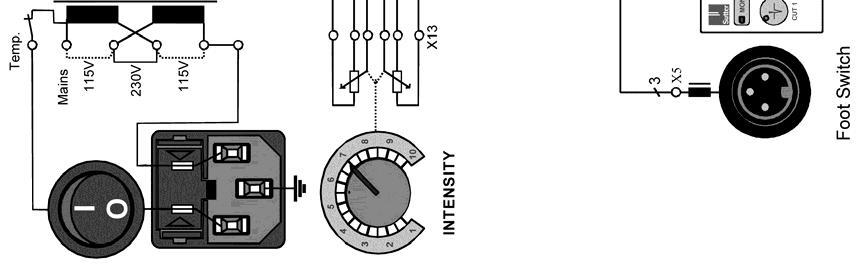
11 2. 5 Circuit Description The complete electronics of the BM-780 II are placed on a printed circuit board (PCB) to which all of the other electric subassemblies are connected by pluggable connectors. According to the block diagram next page, the circuit can be divided into the following functional blocks: Power supply: Power is provided by mains. The socket for the mains cord incorporates also both of the mains fuses. Mains voltage is fed via the mains switch at the front of the unit to the mains transformer. This mains transformer is equipped with a self-resetting overtemperature protection switch which gives protection against overheating. In the standard version, the unit is set to a rated mains voltage of 230V which covers the mains voltage range from 220V to 240V. By change of jumpers at the transformer's terminals by soldering, the BM-780 II can be set to a rated mains voltage of 115V which covers the mains voltage range from 100V to 127V. The transformer has two separated secondary voltages for generating the DC voltages of 15V to supply the control circuits and 50V to supply the RF generator. The power supply is located at the upper left of the PCB. Control: The control coordinates the activation of the RF generator. The following signals meet here and will be connected as follows: Servicing the front keys. Serves to select one of the operation modes. The operation mode will be stored, the operation of the key will be acknowledged by activation of the lamp in the upper left corner of the key. This indicates the selected mode now to be valid. Servicing the lamps for indication of activation when the corresponding operation mode is activated. Interpretation of the signals generated by the handle switch or the foot switch and activation of the RF generator if no NE alarm condition is present. Interpretation of the signal generated by the NE monitoring circuit. On NE alarm, activation of the RF generator is inhibited, the red alarm lamp at the front pad will blink and an intermittent audible alarm will be generated on attempt of activation of a monopolar operation mode. Keying of the activation and alarm tones. Setting of the pulse pattern generator in the driver circuit of the power stage according to the selected operation mode. Adaptation of the setpoint generator signal according to the selected operation mode. Setting of the relays in the energy flow path according to the selected operation mode. 8 V 2.1
12 V 2.1 9
13 RF generator: Consists of the two blocks driver/modulator and power stage. The power stage is a switchmode amplifier which acts on the output transformer T1 in monopolar operation mode and on the output transformer T2 in bipolar operation mode. The setting of output power is performed by setting the duty cycle of the drive signal (switch-on time relative to the period time of the drive signal, PWM). The power stage activates the sound generator directly. The driver/modulator generates the pulse pattern which drives the power stage according to the selected operation mode. The power setting by variation of the duty cycle (pulse with modulation) is also performed here. Setpoint generator and overdose fault monitor: The setpoint generator generates two identical analogue signals which represent the power setting. Depending on the operation mode selected, there is an adaptation of this analogue signals. For safety reasons, this setpoint generator exists twice. In this way a fault of the setpoint generator cannot result in a faulty increase of RF output power since a supervising circuit compares the actual value with an identical setpoint value generated in parallel. If these values are not identical then the overdose fault monitor interrupts the energy flow path to the RF generator by relay K1. Handpiece control: The BM-780 II can be activated by a switch in the handle. This switch is referred to the active electrode, the other terminal is connected to the outer conductor of the coaxial plug of the handle. The handpiece control circuit imposes a medium frequency AC voltage to the terminals of this switch by means of an isolation transformer T3 between patient circuit and control circuit. On operation of the switch, this voltage will be shorted which will be recognised by the handpiece control circuit and results in the generation of a digital signal fed to the control circuit. NE monitor: Single-plated or split-plated neutral electrodes can be connected to the BM-780 II. The neutral electrode's plug has two contacts in all cases. Also in case of single-sectored electrodes both of this contacts are used, where a two-cored cable is connected to the electrode area with both of its cores at separated sites. In this way it is possible to monitor a neutral electrode to be connected to the unit at all and the cable to have no interruption. In case of double sectored electrodes, the contact of the electrode to the patient's skin can be monitored additionally in this conductor loop. The NE monitoring circuit imposes a medium frequency AC voltage across both of the terminals of the NE socket by means of a isolation transformer T4 between patient circuit and control circuit. In case of single-plated electrodes, this voltage will be shorted. In case of split electrodes, the transition resistance of the patient's skin becomes effective. In both cases, the drop of the medium frequency AC voltage will be recognised. The system is tuned in a manner that exceeding a resistance of 270 Ohms between the NE terminals results in generation of a digital signal fed to the control circuit which results in disabling of monopolar operation modes. 10 V 2.1

14 V
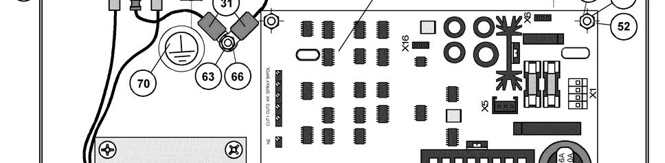
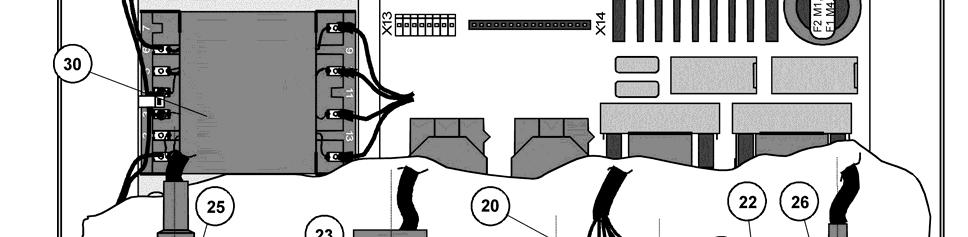
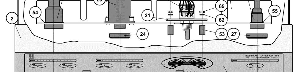
15 3. Disassembling and Reassembling of Subassemblies and Parts 3. 1 Subassemblies and Mechanical Parts for BM-780 II Position Designation Ordering Code 1 Case top Case bottom with front plate Membrane keypad with keys Rotary knob Rotary knob pointer Rotary knob cover Mains cord socket Holder for mains fuse cartridges Mains switch Equipotential connector Potentiometer for power setting with connection cable Flange for potentiometer Mounting angle for sockets with isolation cup for NE socket Neutral electrode socket with connection cable Spacer for NE socket Active electrode socket with connection cable Bipolar socket with connection cable Spacer for bipolar socket Foot switch socket with connection cable Mains transformer with cable tree Set of protective earth conductor cables RF generator PCB V 2.1
16 Set of small mechanical parts, consisting of: Case stand 52 Aluminium spacer 7/4.2 X 20mm for PCB fixation 53 Plastic spacer 6/3.4 X 10mm for potentiometer 54 Spring ring 18 X 1.2mm for monopolar socket 55 Spring ring 12 X1.0mm for bipolar socket 56 Cable clip 60 Washer 3.2 X 6mm for case top fixation 61 Washer 4.3mm for PCB fixation 62 Lock washer S3 for potentiometer fixation 63 Lock washer S4 for PCB and protective earth connector fixation 64 Contact washer 4.2mm for mains transformer fixation 65 Hex nut M3 for potentiometer fixation 66 Hex nut M4 for PCB and protective earth connector fixation 67 Tallowdrop screw M4 X 8 for mains transformer fixation 68 Self tapping screw 2.9 X 9.5mm for case top fixation 70 Stick-on symbol "Protective Earth" 71 Stick-on symbol "High Voltage" Fuse cartridge M1,6A (1.6A medium blow, fuse F2 at PCB) Fuse cartridge M4A (4A medium blow, fuse F1 at PCB) Fuse cartridge T0,8AH (0.8A slow blow, for mains voltage 220V to 240V) Fuse cartridge T1,6AH (1.6A slow blow, for mains voltage 100V to 127V) V
17 14 V 2.1

 at the inside of the front plate. 4.")
18 3.2 Opening and Closing of the Case 1. Disconnect unit from mains and unscrew the 3 Screws (68) at the rim of the case top rear side. 2. Pull case top backwards and take it off of the case bottom. For this purpose, lift front part and press slightly at the front side of the case top from above. 3. For rearranging the case top, push it from behind and manipulate the projecting rim of the top behind the front frame by lifting the unit slightly. Then lift case top at the front side and push it forwards so that it will be pushed over the plastic bolts (51) at the inside of the front plate. 4. Screw in and tighten self tapping screws (68) with washers (60). V
19 3.3 Exchange of Potentiometer for Power Setting (20) 1. Open case according to Lift cover element (6) off of the rotary knob (4) with a sharp edged tool in axial direction. Loosen the center hex nut in the knob under the cover with a grip or socket wrench 10mm and pull the knob from the shaft. 3. Disconnect connector X13 of the potentiometer at the RF generator PCB. 4. Unscrew both of the hex nuts M3 (65) which hold the flange (21) of the potentiometer at the inner side of the front plate. Remove lock washers (62) and Potentiometer with flange from the inside. 5. Disassemble potentiometer from the flange and replace by spare part. 6. Place potentiometer and flange at the bolts at the inner side of the front plate. Note that the spacers (53) are present at the bolts and the terminals of the potentiometer are directed upside. Place and tighten lock washers (62) and hex nuts (65). 7. Rearrange connection X13 at the RF generator PCB. 8. Place rotary knob from the front side and tighten center screw. Note that the knob will have some space to the front and will not jam. Finally, place cover element into the knob. 9. Close unit according to 3.2. Perform functional check and safety check according to Exchange of Mains Switch (12) 1. Open case according to Press mains switch (12) from the inner side outwards. Eventually, the straps at the upper and lower side of the switch body have to be compressed with a screwdriver or else while the switch will be pressed outwards. 3. Pull cable tree as far as possible out of the front and disconnect plugs from the switch. 4. Rearrange flat cable connectors of the cable tree to the spare part according to the wiring diagram in item 2.5, take care for proper positioning. Place new switch into the orifice at the front. Note that the "I" at the rocker is upside, the "O" downside. 5. Close unit according to 3.2. Perform functional check and safety check according to V 2.1
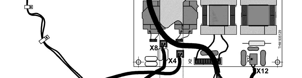
20 3.5 Exchange of Electrode Cable Sockets (23), (25) and (26) For exchange of one of the sockets for neutral electrode (23), for monopolar electrode handle (25) or for bipolar instruments (26) connection, the mounting angle (22) for the electrode sockets has to be disassembled: 1. Open case according to Disconnect the flexible conductor of the membrane keypad at the connection X14 at the RF generator PCB. Attention: The flexible conductor has a plug of its own, don't try to pull the conductor out of this plug! 3. Disconnect the cables of the electrode sockets at the connections X4, X8 and X12 (see wiring diagram in item 2.5). 4. Unscrew the M4 hex nuts which fix the mounting angle (22) with a 7mm socket wrench. Remove nuts (66) and washers (61). 5. Lift mounting angle and tilt it slightly backwards to take it out to the backside passing the edge at the front plate and passing over the fixing bolts. 6. For exchange of the neutral electrode socket (23), stick a 6mm hexagonal socket screw key into the socket from the front side and unscrew socket out of the isolation cup (turn right). If the isolation cup is damaged then the mounting angle (22) with the isolation cup riveted on it has to be changed, where the not damaged components have to be changed from the old to the new angle. Note to change also spacer (24) at the collar of the isolation cup. On placing at the new part, the recessed edge must be directed to the outside. 7. Place new socket into the cup, screw it by hand and tighten it with the hexagonal socket screw key. Take care that the fine pitch thread in the plastic will not be damaged by odd insertion or by too high fastening torque. 8. For exchange of the monopolar electrode socket (25), the spring ring (54) at the inner side of the mounting angle has to be removed with a spring ring grip. Take socket out of the orifice from the front side. Place spare part from the front side into the orifice, note that the protrusion that shall inhibit turn will fit into the recess in the angle. Rearrange spring ring. 9. For exchange of the bipolar socket (26), remove the spacer (27) from the collar of the socket and the spring ring (55) at the inner side of the mounting angle with a spring ring grip. Take socket out of the orifice from the front side. Place spare part from the front side into the orifice, note that the protrusion that shall inhibit turn will fit into the recess in the angle. Rearrange spring ring. Place spacer and verify that the recessed edge is directed to the outside. V
21 10.For rearrangement of the mounting angle it must be verified that both of the spacers (24) and (25) are placed correctly with the recessed edges directed to the outside. Then place the whole subassembly from the backside into the unit while the mounting angle is slightly tilt to the backside to guide it over the fixing bolts. If the spacers are too loose at the collars of the sockets and drop down then, for this procedure, the unit should be placed on an oblique underground or be held in an oblique position by a second person. Push mounting angle towards the front as far as possible and verify that all sockets are proper centered and even in the front. If there is a problem to get the sockets all even to the front, then one of the spacers is probably placed wrong. 11.Place washers (61) and nuts (66). On tightening, press mounting angle with the other hand towards the front plate. 12.Reconnect connector of the neutral electrode socket to connection X8, that of the monopolar socket to X4 and that of the bipolar socket to X12 at the RF generator PCB (see wiring diagram in item 2.5). X8 and X4 are identical connections which shall not be interchanged! 13.Reconnect the conductor of the membrane keypad to connection X14 at the RF generator PCB (see wiring diagram in item 2.5). 14.Close unit according to 3.2. Perform functional check and safety check according to Exchange of Foot Switch Socket (28) 1. Open case according to Disconnect cable of the foot switch socket (28) at the connection X5 at the RF generator PCB (see wiring diagram in item 2.5). 3. Unscrew the threaded ring at the inner side of the rear case wall. For this purpose, a special tool is required. With some care, the ring may also be loosened with a screwdriver, the blade of it must be inserted in one of the slots from the side. Slide threaded ring backwards over the EMI suppression element at the cable and the plug and remove socket from outside. 4. Place spare part from the rear outside into the orifice, fit the protrusion into the notch to avoid turning and slide threaded ring over the cable. Screw ring by hand at the socket and verify that the ring will not be tilted when placed on the thread else the plastic fine-pitch thread may be damaged. On correct placing the ring must be turnable easily by hand. Tighten ring in the same manner as it was loosened. 5. Reconnect cable to the connection X5 at the RF generator PCB (see wiring diagram in item 2.5). Fix cable with new cable clip at the board fixation at the right front. 6. Close unit according to 3.2. Perform functional check and safety check according to V 2.1
22 3.7 Exchange of Membrane Keypad (3) 1. Open case according to Disconnect flexible conductor of the membrane keypad (3) from the connection X14 at the RF generator PCB. Note: The flexible conductor has a plug of its own, don't try to pull it off of this plug! 3. Pull cover element (6) off of the rotary knob (4) in axial direction by use of a sharp edged tool. Loosen the center hex nut in the knob under the cover with a 10mm hexagonal socket wrench and pull the knob from the shaft. 4. Tear the self-adhesive membrane keypad from the front plate, pull flexible connector through the orifice in the front plate. 5. Clean front plate from residual glue and clean the edges of the fitting area with a grease solvent. 6. Peel off protective cover from the spare part. Put connector through the orifice in the front plate and stick on membrane keypad. Place first in the area near the potentiometer hole. Then rub the whole area to insure total attachment. The stick-on with correct matching requires some practise. If possible, exercise with the old part before. 7. Reconnect plug of the membrane keypad to connection X14 at the RF generator PCB (see wiring diagram in item 2.5). 8. Place rotary knob from the front side and tighten center screw. Note that the knob will have some space to the front and will not jam. Finally, place cover element into the knob. 9. Close unit according to 3.2. Perform functional check and safety check according to Exchange of Mains Cord Socket (10) 1. Open case according to Disconnect connectors of the mains cable tree and the protective earth conductor from the mains cord socket (10) at the inner side. 3. Press latching flaps at the inner side of the rear case wall together and press socket outwards. 4. Change fuse holder with fuse cartridges from the old part to the spare part. 5. Place new part with the fuse holder upside from the outside, press it inwards and latch it. 6. Reconnect protective earth connector to the lower terminal. Reconnect terminals of the mains cable tree at the upper terminals (see wiring diagram in item 2.5). 7. Close unit according to 3.2. Perform functional check and safety check according to 4.4. V
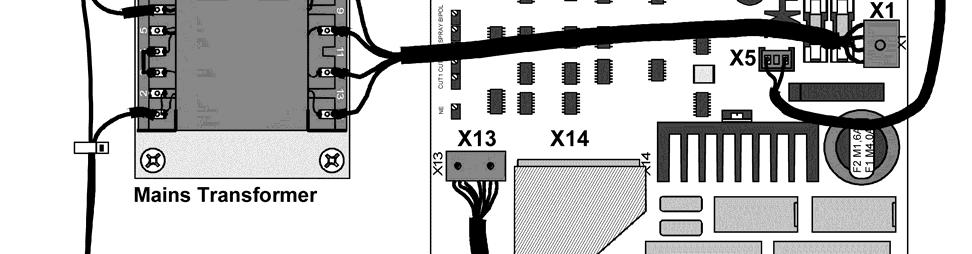
23 3.9 Exchange of Mains Transformer with Cable Tree (30) 1. Open case according to Disconnect terminals of the cable tree from the rear side of the mains cord socket (10). 3. Press mains switch (12) from the inner side outwards. The straps at the upper and lower side of the switch body may have to be compressed with a screwdriver or else while the switch will be pressed outwards. 4. Pull cable tree as far as possible out of the front and disconnect plugs from the switch. 5. Disconnect secondary connector of the transformer from the connection X1 at the RF generator PCB (see wiring diagram in item 2.5). 6. Unscrew the four fixing screws (67) of the transformer at the case bottom and take transformer with cable tree (30) out of the unit. 7. According to item 4.3, check mains voltage setting of the spare part for identity with local mains voltage and designation at the unit's rear side. 8. Assemble spare part with the mains cable tree directed to the left by means of the screws M4 X 8 (67) and the contact washers (64) at the case bottom. Note that the sharp edges at the contact washers are directed towards the sheet of the case bottom. These edges ensure the protective earth connection of the transformer core to the case through the enamel. 9. Reconnect connector of the transformer to connection X1 at the RF generator PCB (see wiring diagram in item 2.5). 10.Put the end of the cable tree for connection to the mains switch through the orifice in the front and pull it out as far as possible. Connect terminals of the cable tree to the mains switch (12) according to the wiring diagram in item 2.5, note for correct connection according to the designated colours. Place switch into the orifice at the front. Note that the "I" at the rocker will be upside, the "O" downside. 11.Reconnect both of the flat connectors of the mains cable tree to the terminals at the mains cord socket (10). 12.Close unit according to 3.2. Perform functional check and safety check according to V 2.1
24 3.10 Exchange of RF Generator Printed Circuit Board (40) It is not within the scope of the service concept of the BM-780 II to repair faults at the RF generator board by soldering the faulty components performed by external service partners. If a fault cannot be eliminated by checking the connections, the secondary voltages of the transformer or the fuses F1 and F2 then the board shall be changed for a preadjusted new one. An exchange service is offered for boards which have no mechanical damages and which are protected against the effects of electrostatic discharge. 1. Open case according to Disconnect flexible conductor of the membrane keypad (3) from the connection X14 at the RF generator PCB. Note: The flexible conductor has a plug of its own, don't try to pull it off of this plug! 3. Disconnect cable of the potentiometer (20) from connection X13 at the left side of the RF generator PCB. 4. Disconnect cable of the foot switch socket (28) from connection X5 and secondary connector of the transformer (30) from connection X1 at the rear right of the RF generator PCB. 5. Disconnect cables of the electrode sockets (23), (25) and (26) from the connections X8, X4 and X12 at the front of the RF generator PCB. 6. Unscrew the four nuts at the corners with a 7mm socket wrench. Remove nuts and lock washers and take the board out of the unit upwards. 7. Before reassembling of the spare part, note that each of the four fixing bolts at the corners of the board is equipped with a spacer 7/4,2 X 20 (52). The plastic bolt in the middle is no fixing element but prevents vibrations of the board on transport which may drag the SMD soldering joints. On placing the board into the unit, note that there is no cable under the board. 8. Fix board with lock washers (63) and nuts (66). 9. Rearrange connector of the NE socket (23) to X8, connector of the monopolar socket (25) to X4 and connector of the bipolar instrument socket (26) to X12 at the front of the board according to wiring diagram in item Rearrange connector of the foot switch socket (28) to X5 and secondary connector of the mains transformer (30) to X1 at the rear right of the board according to wiring diagram in item Rearrange connector of the potentiometer (20) to X13 and the connector of the membrane keypad (3) to X14 right from the middle of the board according to wiring diagram in item Check settings according to item 4.2 and correct if required. Perform functional check and safety check according to 4.4 and close unit according to 3.2. V
25 4. Service Adjustments and Checks 4.1 Visual Checks and Function Checks At the end of service routines and in the course of periodic safety checks, visual and functional checks are to be performed. This requires the following test means: Test cable with 1/4'' coax plug with both of the contacts connected together. Monopolar electrode handle with finger switch, for 4mm electrodes (standard accessory) Test cable with 4mm plug (to plug into the electrode handle). Bipolar test cable (special accessory). Alternatively, the bipolar instrument connection cable of the standard accessory may be used in combination with a bipolar forceps where the current can be conducted from its legs by means of clamps and test cables. Foot switch of the standard accessory. RF power meter for RF electrosurgery units. As long as there is no output power to be adjusted and only the qualitative presence of RF current is to be checked, an incandescent bulb with 230V/60W may be used. IEC safety tester. Visual checks and functional checks are to be performed as follows: 1. At the rear side of the unit, unplug mains cord from the mains cord socket and check it for damages. Check mains cord socket for damages and proper fixation. Take fuse holder out of the mains cord socket (bend flaps at the edges slightly towards the inside with a sharp means), take fuse cartridges out of the holder and check them for proper rated current and blow characteristic. On connection to mains voltage 220V to 240V: T 0,8AH (0.8A slow blow characteristic); on connection to mains voltage 100V to 127V: T 1,6AH (1.6A slow blow characteristic). Then reassemble again. 2. Check labellings at the rear side of the case for readability. 3. Connect unit to mains and switch power on. Check mains switch at the front for proper function, damage and proper fixation. 4. Check rotary knob for power setting for proper fixation at the shaft and proper range of turning angle. The knob shall not jam at the front. 5. Check membrane keypad for damage. Operate the five keys for operation modes in sequence and check for proper perceptibility of the snapover (click point) on pressing the pads. Key operation must be acknowledged by the unit by lighting the lamp in the upper right corner of the key field which indicates the selected operation mode. 22 V 2.1
26 6. The red lamp above the neutral electrode socket must blink if there is no plug inserted into the neutral electrode socket. Connect foot switch and operate. On selection of a monopolar operation mode, an intermitting alarm must be audible. Insert shorted test plug. The red lamp must stop blinking. 7. Select one current mode from the fields "Monopolar Cut", "Monopolar Coag" and "Bipolar Coag" and operate foot switch. The activation indicator lamps in the upper left corners of the key field of the corresponding current mode must flash and a continuous activation tone must be audible. 8. Connect unit to RF power meter or incandescent bulb by means of the NE test cable and the monopolar handpiece with test cable plugged in. Set RF power meter (if used) to the rated load resistance according to item 2.2 or the very next value. Select current mode "Cut 1" and operate foot switch. Turn rotary knob over the whole range of turn. The indicated output power or the brightness must change continuously and in the sense of setting. 9. Set rotary knob to maximum and and activate all monopolar current modes by finger switch and by foot switch successively. Check for accordance with the rated maximum power according to item Connect unit to RF power meter or incandescent bulb by means of the bipolar test cable, select "Bipolar Coag" and operate foot switch. Check for accordance with the rated maximum power according to item Check resistance of the protective earth connection and low frequency leakage currents according to IEC by means of a safety tester. 4.2 Adjustments at the RF Generator PCB As a spare part, the RF generator PCB is preadjusted completely at the manufacturer's site, so no further adjustments are required on exchange. However, if there would be the requirement for a correction of adjustment then proceed as follows: Adjustment of neutral electrode monitoring circuit For this purpose, a voltmeter and a 1/4'' coax plug with a 270 Ohms resistor soldered between its contacts are required as additional test means. 1. Connect plug with 270 Ohms resistor to the NE socket. 2. Connect voltmeter to the outer pins of X16 in the middle of the rear side of the RF generator PCB and switch mains power on. 3. Adjust trimmer "NE" at the left of the rear of the board so that a voltage of 2.3V is present at X16 while the alarm is no more active. 4. Pull test plug out of the NE socket. The red alarm lamp must start blinking. V
27 Bipolar coag.: Set to Ohms 5. Spray coag.: Set to Ohms 4. Contact coag.: Set to Ohms 3. Cut 2: Set to Ohms 2. Cut 1: Set to Ohms 1. With 270 Ohms at NE: Set to 2.3 Volts at X16 X13 X16 X14 X5 X6 F2 M1,6A F1 M4,0A X4 X1 X2 X12 X8 NE CUT1 CUT2 KK SPRAY BIPOL NE VT BM-780 II Adjustments at the RF Generator PCB 24 V 2.1
28 Adjustment of output power This adjustment requires a RF power meter with variable load resistor. 1. Connect neutral electrode socket of the unit by means of test cable and monopolar socket by means of handpiece with a test cable plugged in to the RF power meter. 2. Set RF power meter to 250 Ohms. Switch on unit and set power to maximum. Select current mode "Cut 1" and activate unit. Adjust trimmer "CUT I" so that the RF power meter displays 80 Watts. Prior to each of the following adjustments, this adjustment has to be performed or checked since all the other adjustments are based on this. Change of the setting of trimmer "CUT I" effects a change of all power adjustments! 3. Select current mode "Cut 2" and activate unit. Adjust trimmer "CUT II" so that the power meter displays 70 Watts. 4. Set RF power meter to 200 Ohms. Select current mode "Contact Coag" and activate unit. Adjust trimmer "KK" so that the RF power meter displays 70 Watts. 5. Set RF power meter to 400 Ohms. Select current mode "Spray Coag" and activate unit. Adjust trimmer "SPRAY" so that the RF power meter displays 60 Watts. 6. Connect RF power meter to the bipolar instrument connection socket of the unit by means of the bipolar test cable (alternatively connections of test clips at a bipolar forceps). Set RF power meter to 50 Ohms. 7. Select current mode "Bipolar Coag" and activate unit. Adjust trimmer "BIPOL" so that the RF power meter displays 70 Watts. On check of the output powers, the measured values may differ up to +/-20 Percent from the rated powers as stated in item 2.2. V
 and exchange of the mains fuse cartridges in the mains cord socket: Open unit according to item 3.2.")

29 4.3 Voltage setting in the Mains Circuit The BM-780 II can be set to both of the mains voltage ranges 100V to 127V and 220V to 240V which are most common in the world by changing the wiring of the primary of the mains transformer (requires soldering iron) and exchange of the mains fuse cartridges in the mains cord socket: Open unit according to item 3.2. On change to range 100V to 127V, take fuse holder out of the mains cord socket and replace both of the fuse cartridges (5 X 20mm) by T 1,6AH (1.6A slow blow). Unsolder the jumper between the terminals 3 and 4 of the mains transformer and install two jumpers between the terminals 2 and 3 as well as 4 and 5. On change to range 220V to 240V, take fuse holder out of the mains cord socket and replace both of the fuse cartridges (5 X 20mm) by T 0,8AH (0.8A slow blow). Unsolder both of the jumpers between the terminals 2 and 3 as well as 4 and 5 of the mains transformer and install a jumper between the terminals 3 and 4. Correct or renew the label above the mains cord socket which indicates the fuse value. Close unit according to item 3.2 and perform functional and safety checks according to item V 2.1
30 4.4 Safety Checks The manufacturer advises to perform the following checks on the unit at least every 24 months by qualified persons who have the necessary training, knowledge and practical experience to perform these checks and who are fully competent to carry out such work in an independent and responsible manner. Visual inspection: Check the unit and its accessories for mechanical and functional damage or defects. Check all safety relevant labels for readability. Check the fuse cartridges for compliance with rated current and blow characteristics. Perform functional test in accordance with operating instructions. Check for increase in output power in accordance with the direction of turn of the power setting knob. Check for accordance of setpoint value and actual value of the maximum output power to the rated load resistances at both outputs at all available operation modes according to item 2.2. Check for acoustic and optical signals on activation. Carry out electrical checks according to the test report sheet for periodic safety checks. Leakage currents shall not exceed 1.5 times the value measured first and additionally not exceed the limits. The values measured first are contained in the test report attached. We recommend recording of all safety checks and related results in an equipment log. If the unit is not fully reliable and/or safe to operate, it must either be repaired or the user must be informed of the potential hazards involved in operating the unit. V
31 Periodical Safety Check Test Report Tester:... ID No.:... Serial No.: BM-780 II... Owner: Manufacturer: Sutter Medizintechnik GmbH Kind of Unit: RF Electrosurgery Unit Type: BM-780 II Year of Production:... Test Standard: EN Test Result: 1. Measurements refer to reverse of this test report 2. Points of non-compliance: No faults or faults which do not concern safety. The unit may be operated for further use. 4. The unit may be operated for further use if the faults mentioned above are removed. 5. Errors which require maintenance or repair of the unit before next operation else patients, users or third persons may be object of hazard. Date: Signature: Next date of check : Test report sheet for periodically safety checks, front face 28 V 2.1
32 Tester: Current No.: Test Report: BM-780 II Serial No.: Type label 2. User's instruction manual 3. Labelling 4. Operation elements 5. Genuine accessories? (Else designation of manufacturer) 6. Visual check of RF connection cords 7. Foot switch 8. Operation mode of neutral electrode marked 9. No output power when neutral electrode missing 10. Monitoring circuit of the neutral electrode 11 Check for operation of hand switch and foot switch control 12 Check for optical and acoustic signal on RF activation 13 RF power measurement (maximum at nominal resistance) Cut 1 at 250 Ohms (80W 15W): Cut 2 at 250 Ohms (70W 12W): Contact coagulation at 200 Ohms (70W 12W): Spray coagulation at 400 Ohms (60W 12W): Bipolar coagulation at 50 Ohms (70W 12W): Correct Uncorr. N/A Comm.... Watts... Watts... Watts... Watts... Watts Comments: Electrical measurements according to IEC 60601: 14. Measurement of protective earth conductor resistance: Low frequency leakage current, normal condition:... A 16. Low frequency leakage current, single fault condition:... A 17. Enclosure leakage current, normal condition:... A 18. Enclosure leakage current, single fault condition PE conductor:... A 19. Enclosure leakage current, single fault condition mains:... A 20. Patient leakage current, normal condition:... A 21. Patient leakage current, single fault condition PE conductor:... A 22. Patient leakage current, single fault condition mains:... A 23. Patient leakage current with voltage in parallel to applied part:... A 24. ditto, interchanged phases:... A Unit checked at... From:... Test report sheet for periodically safety checks, reverse V
33 5. Fault Diagnosis BM-780 II Fault Probable Cause Troubleshooting The display button above the No mains voltage Check mains supply mains switch does not light up, elements at the front remain dark, no operation of the unit No or no proper connection of Check mains cord connection mains cord at wall outlet or unit Unit not switched on Switch on unit Failure of mains fuse Check fuses in mains cord socket of the unit and replace if required. Check designation of mains voltage at the rear of the unit, if required then change unit to proper mains voltage according to item 4.3. If mains fuse blows again immediately then a fault in the mains transformer is present. No current mode selected Select current mode at the front panel The display button above the mains switch is illumined, but elements at the front remain dark, no operation of the unit Fuse F2 at the secondary of the mains transformer blown, fault in the control circuit of the RF generator PCB Exchange board if fuse blows immediately again The display button above the mains switch is illumined, elements at the front operate normally but there is no RF output power and no acoustic signal Fuse F1 at the secondary of the mains transformer blown, fault in the RF generator circuit Fault of the power setting potentiometer or its connection Exchange board if fuse blows immediately again Exchange potentiometer 30 V 2.1
34 Authorized and released for publication Distributor: Manufacturer: Sutter Medizintechnik GmbH Tullastr Freiburg / Germany Tel. +49 (0) Fax +49 (0) info@sutter-med.de REF:1112; V2.1; January 2013 Sutter Medizintechnik. Änderungen vorbehalten / Subject to change. REF: 1112 M01. Gedruckt auf chlorfreiem Papier V
Compact System NRGS 11-2 NRGS Original Installation Instructions English
 Compact System NRGS 11-2 NRGS 16-2 EN English Original Installation Instructions 810366-05 1 Contents Important Notes Page Usage for the intended purpose...4 Safety note...4 LV (Low Voltage) Directive
Battery Chargers Sealed or Valve Regulated Lead Acid Batteries Model: PSC AP
 Battery Chargers Sealed or Valve Regulated Lead Acid Batteries Model: PSC-124000AP OPERATING PROCEDURES AND SAFETY INSTRUCTIONS CAUTION: TO PREVENT THE RISK OF ELECTRIC SHOCK, DO NOT REMOVE COVER NO USER
innovations in battery charging
 innovations in battery charging AutomaticBatteryCharger forsealed or Valve Regulated Lead-Acid Batteries Model HPX-60 Series OperatingInstructions WARNING CONCERNING THE REMOVAL OF COVER: CAUTION: TO PREVENT
METROLOGIC INSTRUMENTS, INC. MX001 Industrial Control Interface Installation and User s Guide
 METROLOGIC INSTRUMENTS, INC. MX001 Industrial Control Interface Installation and User s Guide Copyright 2007 by Metrologic Instruments, Inc. All rights reserved. No part of this work may be reproduced,
Battery Chargers Sealed or Valve Regulated Lead Acid Batteries Models: PSC A AND PSC A
 Battery Chargers Sealed or Valve Regulated Lead Acid Batteries Models: PSC-122000A AND PSC-241000A Operating Instructions WARNING CONCERNING THE REMOVAL OF COVER: CAUTION: TO PREVENT THE RISK OF ELECTRIC
SERVICE MANUAL VIO 50 C ELECTROSURGERY
 SERVICE MANUAL VIO 100 C V 1.0.x VIO 50 C V 1.0.x ELECTROSURGERY 80116-221 SERVICE MANUAL VIO 100 C VIO 50 C Registered trademarks of Erbe Elektromedizin GmbH: AUTO CUT, AXUS, BICISION, BiClamp, classiccoag,
Switching DC Power Supply
 99 Washington Street Melrose, MA 02176 Phone 781-665-1400 Toll Free 1-800-517-8431 Visit us at www.testequipmentdepot.com Model 1693, 1694 Switching DC Power Supply INSTRUCTION MANUAL 1 Safety Summary
Battery Chargers Sealed or Valve Regulated Lead Acid Batteries Model: PSC A
 Battery Chargers Sealed or Valve Regulated Lead Acid Batteries Model: PSC-124000A OPERATING PROCEDURES AND SAFETY INSTRUCTIONS CAUTION: TO PREVENT THE RISK OF ELECTRIC SHOCK, DO NOT REMOVE COVER NO USER
MODEL ELC-12/40-CVM-D BATTERY CHARGER
 NATIONAL RAILWAY SUPPLY MODEL ELC-12/40-CVM-D BATTERY CHARGER Installing, Operating and Service Instructions for the ELC-12/40-CVM-D Solid State Charger PLEASE SAVE THESE IMPORTANT SAFETY AND OPERATING
& HIGH CURRENT DC POWER SUPPLIES INSTRUCTION MANUAL
 72-6850 & 72-6852 HIGH CURRENT DC POWER SUPPLIES INSTRUCTION MANUAL Table of Contents Introduction 2 Specification 2 Safety 4 EMC 5 Installation 6 Connections 6 Operation 7 Maintenance and Repair 8 www.tenma.com
User s Manual. Automatic Switch-Mode Battery Charger
 User s Manual Automatic Switch-Mode Battery Charger IMPORTANT Read, understand, and follow these safety rules and operating instructions before using this battery charger. Only authorized and trained service
CURIS. 4 MHz Radiofrequency Generator for different Applications in Microsurgery. 4MHz Radiofrequency
 CURIS 4 MHz Radiofrequency Generator for different Applications in Microsurgery 4MHz Radiofrequency 9 Welcome Sutter Medizintechnik is a family owned and managed company based in Freiburg, Germany. Founded
The EFL 2000/1 & 2 User Guide Test Sieve Shaker. Contents
 The EFL 2000/1 & 2 User Guide Test Sieve Shaker ISSUE 04-02 Contents Description Page 1 Setting Up: 2-8 Unpacking 2 Assembly 3 Clamping Assembly 4 Electrical Connections 5 Sieve Stacking 6 8 Operating
VECTRIX VX-2 SERVICE MANUAL. Version 1.0/May 2011 VECTRIX, LLC
 www.vectrix.com CONTENTS SECTION A: Tools 1 Tools Needed SECTION B: Mechanical Parts 1 Front Fairing 2 Front Console Cover 3 Speedometer Cover 4 Front Vertical Panel Cover-Lower 5 Front Vertical Panel
Abbeon Cal, Inc. Model BD-50E HIGH FREQUENCY GENERATOR OPERATING MANUAL
 Abbeon Cal, Inc. Model BD-50E HIGH FREQUENCY GENERATOR OPERATING MANUAL DESCRIPTION. The Model BD-50E is a rugged tester designed for testing tank lining and other applications where extended use is necessary.
User s Guide. EM3 AEM Monitor
 User s Guide EM3 AEM Monitor 04642-003 EM3 Manufactured By: Encision Inc. 6797 Winchester Circle Boulder, Colorado, USA, 80301-3513 Made in Bulgaria Ph: 800-998-0986 Fax: 303-444-2693 www.encision.com
PREMIER POWER PACK INSTRUCTION MANUAL EN54-4 POWER SUPPLY UNIT INSTRUCTION MANUAL. GLT.MAN-138 Issue: /05/2016 N.R.P.J.
 EN54-4 POWER SUPPLY UNIT INSTRUCTION MANUAL GLT.MAN-138 CONTENTS Introduction to the Premier Power Pack PSU... 2 Changes to EN54-4 (The Fire Alarm Equipment Power Supply Standard)... 3 Indications... 4
DUAL 60V 20A POWER FLEX POWER SUPPLY INSTRUCTION MANUAL
 72-7570 DUAL 60V 20A POWER FLEX POWER SUPPLY INSTRUCTION MANUAL Table of Contents Specification 1 Safety 3 EMC 4 Installation 5 Connections 5 Operation 6 Maintenance 8 Specification General specifications
EB Conveyor Maintenance Guide
 EB Conveyor Maintenance Guide EN-0037 Rev A EB Conveyor Maintenance Guide www.qdraw.com Table of Contents Overview Page 3 Exploded View Of A Standard EB Conveyor Page 4 Preventative Maintenance Page 5
AIR FILTER MODEL NO: AF1000 OPERATION & MAINTENANCE INSTRUCTIONS PART NO:
 AIR FILTER MODEL NO: AF1000 PART NO: 6471160 OPERATION & MAINTENANCE INSTRUCTIONS 1208 INTRODUCTION Thank you for purchasing this Clarke Air Filter. Before you try to use this product, read this manual
Circuit Basics and Components
 Circuit Basics Electric circuits are arrangements of conductors and components that permit electrical current to flow. A circuit can be as simple as a battery and lamp or as sophisticated as a computer.
INFO. SHEET: E1:1 INSPECTION & TESTING OF ELECTRICAL EQUIPMENT
 INFO. SHEET: E1:1 INSPECTION & TESTING OF ELECTRICAL EQUIPMENT This Information Sheet provides guidance on how to carry out User Checks, Formal Visual Inspections and combined Inspection and Tests on portable
SE RV I CE MANUAL. Page 1 of 13
 SE RV I CE MANUAL Technical Data Mechanical Repair Electrical Repairs Calibration Fault Diagnosis Tools and Test Equipment Parts List Page 1 of 13 Technical Data Continuous operation, with intermittent
Product Guide: Series III Pump Control Board Set (RoHS)
") revised 04/08/10 Description: The Series III Pump Control Board Set provides motor drive and pump control for a wide assortment of pumps from Scientific Systems, Inc. The assembly consists of two circuit
revised 04/08/10 Description: The Series III Pump Control Board Set provides motor drive and pump control for a wide assortment of pumps from Scientific Systems, Inc. The assembly consists of two circuit
DC POWER SUPPLY ALIMENTATION C.C.
 DC POWER SUPPLY ALIMENTATION C.C. ISO-TECH IPS 303A 201-3424 ISO-TECH IPS 601A 201-3446 SAFETY TERMS AND SYMBOLS These terms may appear in this manual or on the product: WARNING. Warning statements identify
XENON POWER SUPPLY 4000 Watt Gladiator IV
 XENON POWER SUPPLY 4000 Watt Gladiator IV 220 Volt Equipment Type 62-00049 Rev. February 2003 STRONG INTERNATIONAL a division of Ballantyne of Omaha, Inc. 4350 McKinley Street Omaha, Nebraska 68112 USA
P-600. Technical Manual. Troubleshooting Repairs Replacements
 P-600 Technical Manual Troubleshooting Repairs Replacements Table of Contents P-600 Lift Symptoms and Problems Finding the Problem Before Getting Inside 3 Pneumatic Systems 4 Electrical Systems 5 Mechanical
Dycon D2430 EN54-4 Fire Alarm Power Supply Series
 Dycon D2430 EN54-4 Fire Alarm Power Supply Series Technical Description Installation and Operating Manual Construction Product Regulation 0359-CPR-00434 Page 1 of 14 Contents 1. General... 3 1.1 Product
GENERAL <ELECTRICAL>
 00E-1 GROUP 00E GENERAL CONTENTS HARNESS CONNECTOR INSPECTION................... 00E-2............. 00E-6................. 00E-6 TROUBLESHOOTING STEPS.......... 00E-6 INFORMATION FOR DIAGNOSIS.......
Light Source User Guide
 Light Source User Guide Compact Light Source Range Models covered by this manual: UFO 70/150 CG Glass, White Light - 240V UFO 70/150 CP Plastic, White Light - 240V UFO 70/150 CGC Glass, Colour Wheel (continuous)
Service and Parts Manual. NO LONGER IN PRODUCTION Some service parts may not be available for this product. Otolaryngology Chair.
 thru 391-001 -002 Otolaryngology Chair Serial Number Prefixes: EN, PD & V Service and Parts Manual NO LONGER IN PRODUCTION Some service parts may not be available for this product. 391-001 thru -002 NOTE:
12 amp RMS Battery Charger
 12 amp RMS Battery Charger 83-5000-12 If faults cannot be remedied, contact the Helpline on 020 8391 6767 helpline@hilka.co.uk Manufactured under license by Hilka Pro Imports GUARANTEE This product is
Operating instructions ErgoPack 600 E
 Operating instructions ErgoPack 600 E Operation of the device is only permitted if the operating instructions have been carefully read and understood before use! Declaration of conformity EU declaration
Film-Tech. The information contained in this Adobe Acrobat pdf file is provided at your own risk and good judgment.
 Film-Tech The information contained in this Adobe Acrobat pdf file is provided at your own risk and good judgment. These manuals are designed to facilitate the exchange of information related to cinema
ELECTRIC FENCE ENERGIZER SERVICE MANUAL MODEL 950 SERVICE MANUAL FOR OLLI 950 FENCE ENERGIZERS
 ELECTRIC FENCE ENERGIZER MODEL 950 SERVICE MANUAL Service Manual for OLLI 950 Page 1/16 Date 20.10.2014 Table of Contents...1 1. IMPORTANT SAFETY INSTRUCTIONS...2 2. SPECIFICATIONS...3 3. CONSTRUCTION...4
BLUE LIGHT FOR DYNACO STEREO 120, SCA-80, OR PAT-4 ROCKER SWITCHES
 BLUE LIGHT FOR DYNACO STEREO 120, SCA-80, OR PAT-4 ROCKER SWITCHES 2014 AkitikA, LLC All rights reserved Revision 1p5 April 8, 2014 Page 1 of 16 Table of Contents Table of Contents... 2 Table of Figures...
Model HPX60 Series Automatic Battery Charger User s Manual Rev. 1.0 October 17, 2006
 B R A N D Model HPX60 Series Automatic Battery Charger User s Manual Rev. 1.0 October 17, 2006 For Sales, Support and Service phone: 407-331-4793 fax: 407-331-4708 website: www.xenotronix.com email: information@xenotronix.com
USER MANUAL GEBRUIKSAANWIJZING GEBRAUCHSANWEISUNG SKYLLA 24/100 3-PHASE CE
 USER MANUAL GEBRUIKSAANWIJZING GEBRAUCHSANWEISUNG SKYLLA 24/100 3-PHASE CE SECTIONS: ENGLISH 2 NEDERLANDS 17 DEUTSCH 37 Victron Energy BV De Paal 35 1351 JG Almere-Haven The Netherlands Article number
Series 20 Installation Instructions
 Series 20 Installation Instructions Installation Instructions and field service checklist Read these instructions carefully. Failure to follow them could result in a fire or explosion causing property
NT-500 Technical Support Guide. For use by qualified company approved Technicians
 NT-500 Technical Support Guide For use by qualified company approved Technicians INTRODUCTION The NT-500 is designed to offer the full range of features required to perform radiofrequency denervation The
GENERAL <ELECTRICAL>
 00E-1 GROUP 00E GENERAL CONTENTS HARNESS CONNECTOR INSPECTION................................. 00E-2............. 00E-6................. 00E-6 TROUBLESHOOTING STEPS.......... 00E-6 INFORMATION
ONE TOUCH CONTROL BOX
 ONE TOUCH CONTROL BOX CONVERSION KIT INSTRUCTIONS REMOVAL, INSTALLATION, OPERATION, AND REMOTE CONTROL PROGRAMMING THUNDERSTONE PART #101322 REVISION A JULY 14 TH 2016 2 P a g e INSTALLING THE THUNDER
POWER SUPPLY MODEL XP-800. TWO AC VARIABLE VOLTAGES; 0-120V and 7A, PLUS UP TO 10A. Instruction Manual. Elenco Electronics, Inc.
 POWER SUPPLY MODEL XP-800 TWO AC VARIABLE VOLTAGES; 0-120V and 0-40V @ 7A, PLUS 0-28VDC @ UP TO 10A Instruction Manual Elenco Electronics, Inc. Copyright 1991 Elenco Electronics, Inc. Revised 2002 REV-I
Operating instructions Rotary actuators M135 M140 M150 M180. June 2012 / / EN
 Operating instructions Rotary actuators M135 M140 M150 M180 June 2012 / 118614 / EN General information General information Proof of amendment Copyright Subject to alterations Manufacturer Version Date
User Manual Digital Water Level Indicator for rain water storage tanks
 User Manual Digital Water Level Indicator for rain water storage tanks We congratulate you on the purchase of Digital Water Level measuring device. You have purchased a high-quality product built to the
SERVICE MANUAL SECOH AIR PUMPS
 SERVICE MANUAL SECOH AIR PUMPS (SHOWN AT EL SERIES) MODEL: SLL-20, 30, 40 & 50 EL-60, 80-15, 80-17 & 100 EL-120W, 150 & 200-0 - This manual is not meant to be included in the scope of delivery (for this
MODEL ELC-12/60-D BATTERY CHARGER
 *32198* NATIONAL RAILWAY SUPPLY Installing, Operating and Service Instructions for the 12/60 Solid State Charger MODEL ELC-12/60-D BATTERY CHARGER PLEASE SAVE THESE IMPORTANT SAFETY AND OPERATING INSTRUCTIONS
XENON POWER SUPPLY Watt
 XENON POWER SUPPLY 3000-5000 Watt 220 Volt Equipment Type 62-00016 62-00017 62-00004 (Export) Rev. February 2006 STRONG INTERNATIONAL a division of Ballantyne of Omaha, Inc. 4350 McKinley Street Omaha,
Solstice Electric Fryers SE Series Service Manual
 Solstice Electric Fryers SE Series Service Manual L22-330 R1 (10/12) Notice In the event of problems or questions about your order, contact the Pitco Frialator factory at (603) 225-6684. In the event of
Electronic Ballast EVG 2000-T
 Electronic Ballast EVG 2000-T Operating Manual Table of contents 1 Description 1.1 Advantages of this ballast... 3 1.2 Functional principle... 3 1.3 Energization... 4 1.4 Visualization... 5 1.5 Indications
Operating instructions Actuator and Emergency exit AZ/AZM 200-B30 AZ/AZM 201-B About this document. Content
 1. About this document Operating instructions............pages 1 to 10 Original 1.1 Function This operating instructions manual provides all the information you need for the mounting, set-up and commissioning
C.fm Page 1 Thursday, February 21, :28 AM Raptor user manual
 Raptor user manual 1 mounting bracket 2 swivel lock 3 clamp hole 4 lamp access screws 5 air vents 6 AC input & main fuse 7 cooling fan Thank you for selecting the Martin Raptor. This Martin lighting fixture
MOVING HEAD. User manual CAUTION!
 TM MOVING HEAD OBY-3 User manual CAUTION! contents Features Description of the appearance Inspection. Safety instructions Lamp Installation Rigging Connection with the mains Linking Instruction for gobo
FiveFish Studios PSU-2448Plus+ Assembly Guide
 FiveFish Studios PSU-2448Plus+ Assembly Guide Copyright 2015-2017 FiveFish Audio Revision 1.02-20171105 No part of this document may be reproduced, either mechanically or electronically, posted online
The Powermatic User Guide Test Sieve Shaker
 The Powermatic User Guide Test Sieve Shaker ISSUE 04-02 Contents Description Page 1 Setting Up: 2-8 Unpacking 2 Assembly 3-4 Levelling 4 Electrical Connections 5 Sieve Stacking 6-8 Operating Instructions
Notice Regarding this Upgrade. WARNING! Danger Potential
 Notice Regarding this Upgrade WARNING! Danger Potential Although this kit has been designed to be easy-to-install, and has been tested in many installations; caution must be exercised when installing this
Measurements are expressed in millimeters.
 T-Rex user manual Measurements are expressed in millimeters. 1 Lamp access 2 Focus adjustment 3 Mounting bracket 4 Swivel locks 5 Clamp hole 6 Air vent 190 285 7 AC input & main fuse 8 Microphone 490 164
Operating instruction and technical description
 Operating instruction and technical description EV Simulator for charging devices with charging plug / charging coupler / charging cable type 1 and type 2 as service case Photo: EV simulator/tester with
PRODUCT INFORMATION BULLETIN #3365 DIGITAL MOTOR CONTROL PLATTER SYSTEMS For Serial Number and After
 PRODUCT INFORMATION BULLETIN #3365 DIGITAL MOTOR CONTROL PLATTER SYSTEMS For Serial Number 28640996 and After Record Platter System Identification Numbers Here: Model # Serial # Table of Contents Program
GF-30AC. Ground Circuit Tester COMPLIANCE WESTUSA. Instruction Manual
 GF-30AC Ground Circuit Tester Instruction Manual COMPLIANCE WESTUSA Dear Customer: Congratulations! Compliance West USA is proud to present you with your Ground Fault Circuit Tester. Your instrument features
ACCUSENSE CHARGE SERIES ON/OFF BOARD FULLY AUTOMATIC BATTERY CHARGER
 ACCUSENSE CHARGE SERIES ON/OFF BOARD FULLY AUTOMATIC BATTERY CHARGER SPECIFICATIONS: *Photo for reference only* Part number 8890439 Mode Select: Selects Battery Type Refer to Section 6. IMPORTANT: READ
INSTRUCTION MANUAL PORTABLE APPLIANCE TESTER
 INSTRUCTION MANUAL PORTABLE APPLIANCE TESTER KEW6201A CONTENTS 1. Safe testing 1 2. Procedure of removing cover. 3 2.1 Method of removing the cover. 3 2.2 Method of storing the cover. 3 3. Product summary
Piko Head Unit Piko 3 Piko X Piko U3
 www.lupine.de Piko Head Unit Piko 3 Piko X Piko U3 OWNERS MANUAL Piko 1 Read this manual before using Mounting 2 General: The light and charger are ready for use when delivered. All you have to do is charge
WATERFLUX 3070 Quick Start
 WATERFLUX 3070 Quick Start Battery powered electromagnetic water meter Electronic Revision ER 4.3.0_ up to ER 4.3.4_ (SW.REV 4.2.2_ up to 4.2.5_) KROHNE CONTENTS WATERFLUX 3070 1 Safety instructions 4
4 Electric Circuits. TAKE A LOOK 2. Identify Below each switch, label the circuit as a closed circuit or an open circuit.
 CHAPTER 17 4 Electric Circuits SECTION Introduction to Electricity BEFORE YOU READ After you read this section, you should be able to answer these questions: What are the three main parts of a circuit?
PM-200 POWER SUPPLY MODULE v3.2 ASSEMBLY & INSTALLATION INSTRUCTIONS
 PM-200 POWER SUPPLY MODULE v3.2 ASSEMBLY & INSTALLATION INSTRUCTIONS WARNING: Voltages inside the amplifier CAN & WILL KILL YOU! You MUST know how to work around HIGH VOLTAGE safely. If you do not, get
Maintenance Manual 13 AMPERE POWER SUPPLY 19A704647P1-P3. Mobile Communications LBI-31801C
 C Mobile Communications 13 AMPERE POWER SUPPLY 19A704647P1-P3 CAUTION THESE SERVICING INSTRUCTIONS ARE FOR USE BY QUALI- FIED PERSONNEL ONLY. TO AVOID ELECTRIC SHOCK DO NOT PERFORM ANY SERVICING OTHER
XENON POWER SUPPLY Compact Model 220 Volt Equipment Type
 XENON POWER SUPPLY Compact Model 220 Volt Equipment Type 62-80106 62-80108 62-80109 62-80113 Rev. August 2001 STRONG INTERNATIONAL a division of Ballantyne of Omaha, Inc. 4350 McKinley Street Omaha, Nebraska
Quickie S-11 Service Manual
 Quickie S-11 Service Manual 05 Sunrise Medical Inc. 100740 Rev A Quickie S-11 Troubleshooting Guide INTRODUCTION... 0.1 Specifications VSI Controller... 0.2 Plugs/Connectors... 0.3 Main Wiring Diagram/
To avoid a short cut please file off the right half of the Y-hole flange.
 Fitting instructions for automatic alternator controller for Moto Guzzi with Bosch alternator 1. alternator modification - 2. Fitting - 3. adjustment (ignition only) First remove the connector block of
Using Electricity. Summary Notes. 1. From the Wall Socket Household appliances. Earth wire and safety.
 Using Electricity Summary Notes Section Content 1. From the Wall Socket Household appliances. Earth wire and safety. 2. Alternating and Direct Battery and transformer. Current Circuit diagrams. Current
Professional Wireless Products
 Page 1 of 6 093115 Communications Power Supply and Battery Management Controller Page 2 of 6 1.0 Introduction The 093115 is a 13.8 volt 15amp transformer isolated switch mode down converter designed to
PL900 ILLUMINATOR. Fiber-Lite. Operation Manual. Setup. Fiber Optic Connection A PRODUCT OF DOLAN-JENNER INDUSTRIES. Voltage Selection:
 PL900 ILLUMINATOR A PRODUCT OF DOLAN-JENNER INDUSTRIES Setup Voltage Selection: Operation Manual Read and review the instructions on the label covering the power entry module and the instructions in this
D.fm Page 1 Wednesday, March 5, :21 PM Raptor user manual
 Raptor user manual 1 mounting bracket 2 swivel lock 3 clamp hole 4 lamp access screws 5 air vents 2001-2002 Martin Professional A/S, Denmark. All rights reserved. No part of this manual may be reproduced,
Belt Conveyor Pull Rope Switch Types HEN, HEK and SEM OPERATING INSTRUCTIONS
 Belt Conveyor Pull Rope Switch Types HEN, HEK and SEM OPERATING INSTRUCTIONS 2 CE-Sign and Conformity The device meets the requirements of the valid European and national regulations. Conformity has been
innovations in battery charging
 innovations in battery charging AutomaticBattery Charger for Sealed or Valve Regulated Lead-AcidBatteries Model HPX-10 Series OperatingInstructions POWER/FLOAT FAST CHARGE FAULT (shorted or reversed output
Electronic Dynamo Regulator INSTRUCTION MANUAL. COPYRIGHT 2014 CLOVER SYSTEMS All Rights Reserved
 DRM TM DRM-HP TM Electronic Dynamo Regulator INSTRUCTION MANUAL COPYRIGHT 2014 CLOVER SYSTEMS All Rights Reserved INTRODUCTION The Clover Systems DRM is a state-of-the art all-electronic voltage and current
Service Manual. VIO 300 S V 1.0.x. VIO 200 S V 1.2.x. V 1.1.x V 1.2.x 02.08
 ERBE VIO 300 S V 1.0.x V 1.1.x V 1.2.x VIO 200 S V 1.2.x Service Manual SERVICE MANUAL VIO 300 S VIO 200 S Service Manual Art.No. 80116-284 All rights to this manual, in particular rights of duplication,
DX³ RCCBs - ID 4P up to 100 A
 87045 LIMOGES Cedex Telephone number: +33 (0)5 55 06 87 87 Fax: +33 (0)5 55 06 88 88 DX³ s - ID CONTENTS PAGE 1. Description, use... 1 2. Range... 1 3. Overall dimensions... 1 4. Preparation - Connection...
Induction Power Supplies
 Induction Power Supplies 7.5kW; 135 400kHz 480V version (Integral Heat Station) User s Guide Model 7.5-135/400-3-480 SMD Control Brds Rev. D 5/08 Table of Contents 1. Specifications and features...3 2.
SERVICE MANUAL (INTERNATIONAL)
") SERVICE MANUAL (INTERNATIONAL) IMPINGER CONVEYOR OVENS MODEL 1421-000-E, 1454, 1455 WITH PUSH BUTTON CONTROLS Lincoln Foodservice Products, LLC 1111 North Hadley Road Fort Wayne, Indiana 46804 United States
SERVICE MANUAL (INTERNATIONAL) IMPINGER CONVEYOR OVENS MODEL 1421-000-E, 1454, 1455 WITH PUSH BUTTON CONTROLS Lincoln Foodservice Products, LLC 1111 North Hadley Road Fort Wayne, Indiana 46804 United States
RP-4000 Reserve Power Control
 Instruction Manual IM-0580 RP-4000 Reserve Power Control Table of Contents General Information... 2-3 Introduction... 2 Cautions... 2 Receiving/Inspection... 2 Storage... 2 Equipment Return... 2 Identification
Heavy Duty Series (HDS) Installation and user guide
 Installation and user guide") Heavy Duty Series (HDS) Installation and user guide HDS40-50 HDS40-100 (4x50 Watt transducers) (4x100 Watt transducers) www.shipsonic.com a brand of: delta-sistems BV Blokjesplaat 1 4465 BC Goes The Netherlands
Heavy Duty Series (HDS) Installation and user guide HDS40-50 HDS40-100 (4x50 Watt transducers) (4x100 Watt transducers) www.shipsonic.com a brand of: delta-sistems BV Blokjesplaat 1 4465 BC Goes The Netherlands
Section 7 - Troubleshooting Guide
 Section 7 - Troubleshooting Guide Section 7 - Troubleshooting Guide IMPORTANT While this troubleshooting guide provides information to aid in troubleshooting problems with the range, it does not contain
PPS20 COMMUNICATIONS POWER SUPPLY AND BATTERY MANAGEMENT SYSTEM
 PPS20 COMMUNICATIONS POWER SUPPLY AND BATTERY MANAGEMENT SYSTEM 2 Table of Contents Introduction:... 3 1.0: Operation Principles:... 3 1.1: Stand alone supply... 3 1.2: Backed up supply:... 3 1.3: Battery
OBY-5. User manual MOVING HEAD CAUTION!
 TM MOVING HEAD OBY-5 User manual CAUTION! contents Features Description of the appearance Inspection. Safety instructions Lamp Installation Rigging Connection with the mains Linking Instruction for gobo
Order Number MOP C2. Microwave Oven
 Order Number MOP0107026C2 Microwave Oven 2 2001 Matsushita Electric Industrial Co., Ltd. All rights reserved. Unauthorized copying and distribution is a violation of law. 1 Inverter Warning The inverter
FE 35, 40, 55, EC Every time you open the housing, clean the motor with a soft brush.
 FE 35, 40, 55, EC 70 1 Service Manual FE 35, FE 40, FE 55 Electric Trimmers, EC 70 Electric Edger As the design concept of the FE 35 and FE 40 trimmers is almost identical, the descriptions and servicing
Pressure chlorine changeover unit C 7520
 BW 2 24 04 / 1 Content 1. Scope of delivery 2. Device description 3. Installation 4. Operation 5. Shutdown 6. Maintenance 7. Troubleshooting 1 Scope of delivery The chlorine gas changeover unit C 7520
Application Engineering
 Application Engineering February, 2009 Copeland Digital Compressor Controller Introduction The Digital Compressor Controller is the electronics interface between the Copeland Scroll Digital Compressor
EL5600 Series Electric Linear Actuators Installation and Maintenance Instructions
 3581050/5 IM-P358-05 CH Issue 5 EL5600 Series Electric Linear Actuators Installation and Maintenance Instructions 1 Safety information 2 General 3 Installation 4 Commissioning 5 Maintenance IM-P358-05
Heavy Duty Series (HDS) Installation and user guide
 Installation and user guide") Heavy Duty Series (HDS) Installation and user guide HDS20-50 HDS20-100 (2x50 Watt transducers) (2x100 Watt transducers) www.shipsonic.com a brand of: delta-sistems BV Blokjesplaat 1 4465 BC Goes The Netherlands
Heavy Duty Series (HDS) Installation and user guide HDS20-50 HDS20-100 (2x50 Watt transducers) (2x100 Watt transducers) www.shipsonic.com a brand of: delta-sistems BV Blokjesplaat 1 4465 BC Goes The Netherlands
COYOTE ENTERPRISES, INC. 9/10 BLAST WHEEL MAINTENANCE & ASSEMBLY MANUAL
 COYOTE ENTERPRISES, INC. 9/10 BLAST WHEEL MAINTENANCE & ASSEMBLY MANUAL Parts & Machinery for the Abrasive Blast Industry 27301 East 121st Street Coweta, Oklahoma 74429 (918) 486-8411 Fax (918) 486-8412
TX³ RCCBs 2P up to 100 A
 87045 LIMOGES Cedex Telephone number: +33 (0)5 55 06 87 87 Fax: +33 (0)5 55 06 88 88 TX³ RCCBs CONTENTS PAGE 1. Description, use... 1 2. Range... 1 3. Overall dimensions... 1 4. Preparation - Connection...
TS-E TURBO STEAM ELECTRIC COUNTERTOP CONVECTION STEAMER PARTS AND SERVICE MANUAL
 TS-E TURBO STEAM ELECTRIC COUNTERTOP CONVECTION STEAMER PARTS AND SERVICE MANUAL EFFECTIVE JUNE 12, 2017 Superseding All Previous Parts Lists. The Company reserves the right to make substitution in the
SERVICE MANUAL (DOMESTIC & INTERNATIONAL)
") SERVICE MANUAL (DOMESTIC & INTERNATIONAL) DUAL TECHNOLOGY FINISHER MODEL 1960 & 1980 SERIES Lincoln Foodservice Products, LLC 1111 North Hadley Road Fort Wayne, Indiana 46804 United States of America Telephone:
SERVICE MANUAL (DOMESTIC & INTERNATIONAL) DUAL TECHNOLOGY FINISHER MODEL 1960 & 1980 SERIES Lincoln Foodservice Products, LLC 1111 North Hadley Road Fort Wayne, Indiana 46804 United States of America Telephone:
Language specific user manuals are available on
 User Manual WEB Charger for LiFePO 4 Batteries EN User Manual Language specific user manuals are available on www.mascot.no/downloads/usermanuals Bruksanvisning Käyttöohjeet Bedienungsanleitung Mode d
SERVICE MANUAL Aktilite CL16 Ver 1.1
 SERVICE MANUAL Aktilite CL6 Ver. Photocure ASA Hoffsveien 48 NO-0377 OSLO, Norway Phone: +47 22 06 22 0 www.photocure.com Service Manual Aktilite CL6 SERVICE MANUAL Aktilite CL6 Any kind of service should
SERVICE MANUAL ULTIMATE 200
 SERVICE MANUAL ULTIMATE 200 This manual is for: 20 200-120 Ultimate 200 std. 120V 60 Hz 20 200-240 Ultimate 200 std. 240V 50 Hz 20 201-120 Ultimate 200 DMX 120V 60 Hz 20 201-240 Ultimate 200 DMX 240V 50
BLUE LIGHT FOR DYNACO STEREO 120 OR PAT-4 ROCKER SWITCHES
 BLUE LIGHT FOR DYNACO STEREO 120 OR PAT-4 ROCKER SWITCHES 2012 AkitikA, LLC All rights reserved Revision 1p3 April 18, 2012 Page 1 of 15 Table of Contents Table of Contents... 2 Table of Figures... 2 Section