INSTALLATION INSTRUCTIONS
|
|
|
- Suzanna King
- 6 years ago
- Views:
Transcription

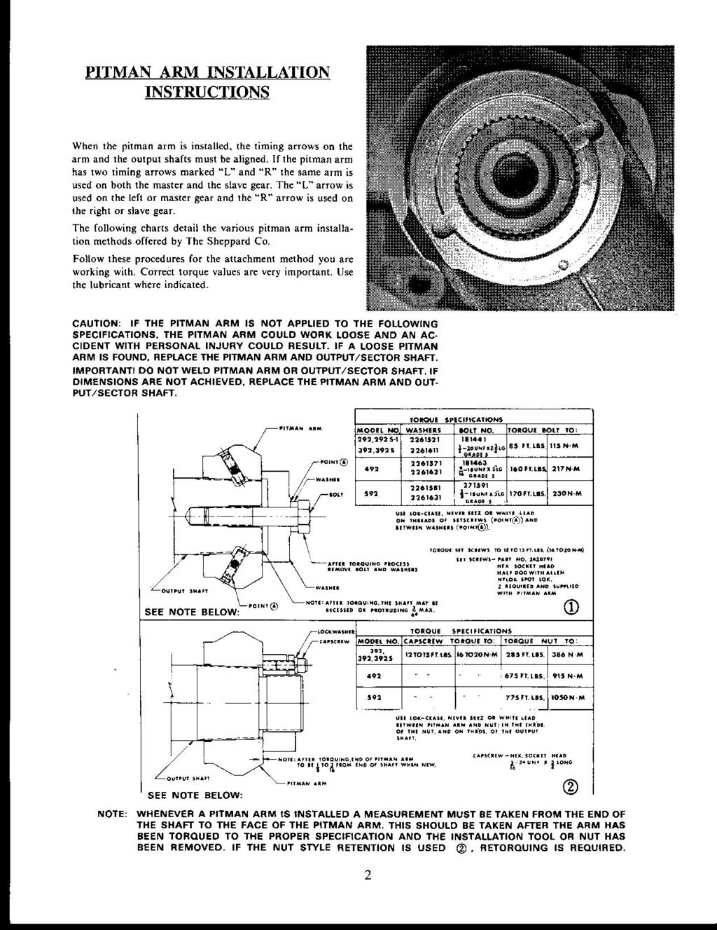
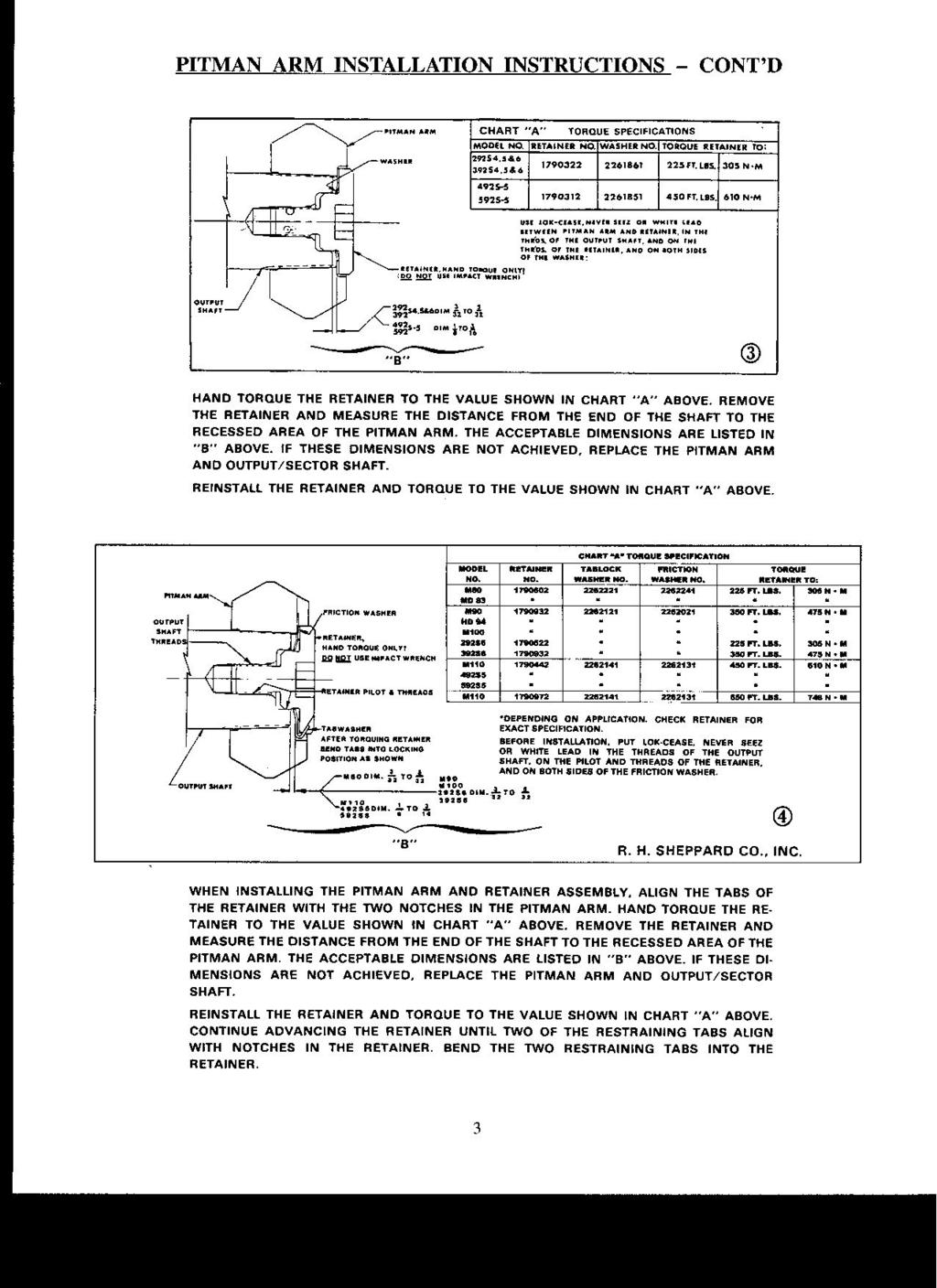
1 INSTALLATION INSTRUCTIONS This Sheppard Power Steering Gear has been manufactured and tested for proper operation prior to shipment. Every effort has been made to ensure that it will provide you with many miles of trouble-free, safe operation. To protect your investment and comply with your warranty, it is important that these instructions be closely followed. 1. Anytime a power steering gear or power steering pump is replaced, the oil and oil filter in the power steering system should be changed. All lines and fittings should be flushed of any possible contaminants. Use the type of fluid specified by the vehicle manufacturer or 15W40 Engine Oil if none is specified. 2. If a power steering pump has been replaced, it should be tested to ensure that its pressure and oil flow are the same as originally specified by the vehicle manufacturer. 3. Transfer the hose fittings from the old steering gear to the new one. Replacing the o-rings is recommended. 4. Install the steering gear on the vehicle. Care should be taken to ensure the mounting bracket or steering gear is not distorted when the bolts are drawn up. This condition could cause binding in the gear. 5. Attach all hoses to the gear or gears. Ensure they are in good condition and routed with no kinks in the line. Refer to the Sheppard Service Manual for proper routing of dual steer systems. On M-Series gears, the inlet and outlet ports are staggered. The inlet port is always the one closest to the output shaft. 6. Install the steering column or intermediate shaft to the steering gear input shaft, ensuring the clamp bolt is torqued to the vehicle manufacturer s specification. 7. Install the pitman arm using the guidelines in this instruction. Take care not to move the arm more than 2 inches in either direction until the draglink has been installed. Over-traveling the piston will prematurely set AUTO relief plungers. 8. Install the draglink on the pitman arm (except slave gears) and torque the fastener to the vehicle manufacturer s specification. Slave gears should not have the draglink installed until the Bleeding procedure is performed. NOTE: If you cannot turn the steering all the way until the stops contact the axle in each direction with the steer tires off the ground, the pitman arm may be mistimed. 9. Fill the power steering system with an approved fluid. Start the engine and let it idle. DO NOT ALLOW THE RESERVOIR TO RUN DRY! 10. IMPORTANT! Set the AUTO relief plungers or adjust the manual relief plungers to obtain proper wheel cut. Use the guidelines in this instruction. 11. Bleed the gear or gears using the guidelines in this instruction. 12. Double-check all fasteners, fittings, hose routings, and check for leaks. Top off the power steering system and return the vehicle to service. 13. Today s systems typically have smaller reservoirs and operate at much higher temperatures than in the past. Regular preventive maintenance is essential to extended steering system life. Follow the OEM's recommendations for power steering fluid and filter change intervals. If you have questions at any time, our entire Service Manual can be found on our website at or contact our Field Service Hotline at
2 2
3 3
4 RELIEF PLUNGERS A relief plunger is placed in each end of all Sheppard steering gears (with the exception of slave gears) to unload steering system pressure prior to the axle stops contacting the axle. One is located in a small hole in the bearing cap cover next to the input shaft. The other plunger is on the opposite end of the steering gear and may be in a hole in the cover, in the hole in the end of a boss sticking out from the cover, or in a cartridge screwed into the cover. The plungers prevent the power steering pump from operating at maximum relief pressure at the end of steering travel. When properly adjusted, the relief plungers reduce system temperature and excessive stress on the mechanical components of the steering system by preventing the axle stops from contacting the axle under full pump pressure. CAUTION: Failure to set or adjust the relief plungers could result in damage to the steering system. Plungers MUST be set or adjusted whenever a steering gear is replaced. AUTO PLUNGERS 1. AUTO plunger gears are identified by the word AUTO in raised letters cast into the side of the steering gear housing and plastic caps on each end of the gear covering the plunger hole. 2. Raise the steer tires off the ground. 3. Start the engine and let it run at idle speed. Ensure the axle stops are set for maximum wheel cut with a minimum of 1" clearance between the tire and any part of the chassis. 4. Set the AUTO plungers by turning the steering wheels from side to side until the axle stops contact the axle. This allows the piston in the steering gear to contact the AUTO plunger assembly and push it back to its set position. The stops MUST contact the axle. 5. Set the vehicle back on the ground. Turn the steering wheel completely from stop to stop. The chassis should not flex when the steering reaches the end of travel. If it does, the AUTO plungers must be reset. Normally you will see a small gap between the axle stop and the axle. 6. Vehicle wheels should be in the straight ahead position.reset AUTO plungers by tapping them in with a 1/4" punch and hammer until you feel the plunger bottom out in the bore. Be careful not to score the plunger bore. Scoring the bore will cause a leak which cannot be repaired. After the AUTO plungers are reset, set them by following steps 2 through 4. 4
5 MANUAL PLUNGERS 1. Your steering gear has manual plungers if you can back them out of the plunger hole with a small flat-bladed screwdriver. 2. Manual plungers are turned all the way in from the factory for minimum wheel cut. Adjust the plungers IN to decrease wheel cut, adjust OUT to increase wheel cut. Use a long, flat bladed screwdriver. 3. Start the engine and let it run at idle speed. Ensure the axle stops are set for maximum wheel cut with a minimum of 1" clearance between the tire and any part of the chassis. 4. With the full weight of the vehicle on the ground, have a helper turn the steer tires full left. Check the gap between the axle stop and the axle on the left steer tire. If it is greater than 1/8" adjust the plunger out (counter clockwise). Adjust the plunger in the end of the gear which the piston has moved toward. If the stop is touching the axle try turning the plunger in then recheck it. NOTE: The plungers are fine thread so it may take several turns to get them properly adjusted. Do not back the head of the plunger out past flush with the end of the hole. The plunger could be ejected from the gear. 5. After making an adjustment, center the steering and recheck the gap at the axle stop. 6. When the steer tires have been turned back and forth about 4 times, rubber will accumulate under the tires and make setting the plungers difficult. Roll the vehicle ahead or back about 1 foot and recheck the gap at the axle stop. 7. Turn the steer tires full right and adjust the opposite plunger for the gap at the right side axle stop using the same procedure. Once the relief plungers are set, no further adjustment is necessary unless tire size or wheel offset is changed. 5
6 BLEEDING AIR FROM STEERING GEARS Most single steering gears can be bled simply by turning the steering wheel all the way from stop to stop after the gear has been installed, lines connected, system filled with fluid, and relief plungers set. Some gears however, require bleeding through a bleeder screw or in the case of dual gear systems, a special procedure. The following guidelines can be used. SINGLE GEAR SYSTEMS If the gear is mounted with the bulge in the housing for the sector shaft hanging below the piston cylinder: 1. With the weight of the vehicle on the ground, start the engine and let it run at idle speed. 2. Turn the steering wheel lock to lock 3 times. Hold the wheel in pressure for about 5 seconds when you reach the lock position in each direction. Center the steering, bleeding complete. If the gear is mounted with the bulge in the housing for the sector shaft sitting above the piston cylinder: 1. Locate the bleeder plug on the sector housing. It will look like a bolt head that a 3/4" wrench would fit. There will be a piece of tape on it covering a 1/8" allen set screw in the center of it. Remove the tape to expose the set screw. 2. Do not remove the bleeder screw from the plug. There is a check ball behind it which likes to get lost. 3. With the weight of the vehicle on the ground, start the engine and let it run at idle speed. 4. With a helper, turn the steering wheel to full left. Open the set screw in the bleeder plug 4 turns. With the bleeder still open, turn the wheels all the way to the right and shut the bleeder. Turn the wheels all the way to the left and repeat the procedure 2 more times. The bleeder should only be open when turning right. If it is open when turning left, air will be forced back into the system. Center the steering, bleeding complete. DUAL GEAR SYSTEMS 1. With the weight of the vehicle on the ground, start the engine and let it run at idle speed. The draglink should be connected to the pitman arm on the main gear but not connected to the salve gear. 2. Turn the steering wheel all the way to the left until the axle stop contacts the axle and hold until the pitman arm on the slave gear moves its full travel. It should move in the opposite direction of the pitman arm on the main gear. 3. Now turn the steering wheel all the way to the right until the axle stop contacts the axle and hold until the pitman arm on the slave gear moves its full travel. 4. Repeat the procedure 3 more times or until there is no air in the system and the slave gear moves freely. NOTE: Avoid moving the pitman arm on the slave gear by hand. Air may be drawn into the system. 5. Turn the steering wheel until the pitman arm on the slave gear lines up with the draglink and install the draglink. 6. Cycle the steering from stop to stop. If a catch is noted, look for bleed plugs on the steering gears. If the gear is mounted with the bulge in the housing for the sector shaft sitting above the piston cylinder, follow the procedure outlined for bleeding a single gear with the bulge in the housing for the sector shaft sitting above the piston cylinder. If both gears have bleeder plugs, bleed only when turning the steering wheel to the right. NOTE: Do not allow the reservoir to run dry at any time. Bleeding is complete when the steering operates smoothly from lock to lock in both directions A 09/04
WARNING. it means the information that follows will help avoid damage to the steering gear.
 SAFETY NTICE STP! Before you begin, please read this manual carefully. The repair procedures outlined in this manual are for repairing the Sheppard Integral Power Steering Gear. To ensure safe and reliable
INSTALLATION INSTRUCTIONS
 INSTALLATION INSTRUCTIONS PERFORMANCE AT THE WHEELS KIT W155-5 CHRYSLER 8 3 /4" & 9 3 /4" REAR AXLES Thank you for choosing STAINLESS STEEL BRAKES CORPORATION for your braking needs. Please take the time
INSTALLATION INSTRUCTIONS
 INSTALLATION INSTRUCTIONS PERFORMANCE AT THE WHEELS KITS W156-6 & W156-7 1965-74 MOPAR B & E BODY Thank you for choosing STAINLESS STEEL BRAKES CORPORATION for your braking needs. Pleases take the time
INSTALLATION INSTRUCTIONS
 INSTALLATION INSTRUCTIONS PERFORMANCE AT THE WHEELS KIT W125-42 GM 10 & 12 Bolt Rear Axles with Staggered or non-staggered Shocks with C-Clips Thank you for choosing STAINLESS STEEL BRAKES CORPORATION
HYDRAULICS. TX420 & & lower. Hydraulic Tandem Pump Removal. 4. Remove the LH side panel (Fig. 0388).
.") TX420 & 425 240000299 & lower 4. Remove the LH side panel (Fig. 0388). Hydraulic Tandem Pump Removal Note: Cleanliness is a key factor in a successful repair of any hydraulic system. Thoroughly clean all
TX420 & 425 240000299 & lower 4. Remove the LH side panel (Fig. 0388). Hydraulic Tandem Pump Removal Note: Cleanliness is a key factor in a successful repair of any hydraulic system. Thoroughly clean all
Installation Instructions
 Installation Instructions Rear Disc Brake Conversion Kit Item # RC4001, RC4001X Applications: Mopar 7.25, 8.25, 9.25 Axles Thank you for choosing Leed Brakes for your automotive product needs. Before you
SAF-T-LINER MVP-EF PARTS MANUAL. Steering Section. Steering. Page /96
 Page 8-1 Column and Wheel Page 8-2 Column and Wheel Item Part Num. Number Qty. Description Notes 1 61320220 1 Column -, Assembly, Fixed 61320209 1 Column -, Assembly, Single Lever C4220-02-000 End 10/12/94
Maintenance Information
 16573370 Edition 2 February 2014 Air Grinder 99V Series Maintenance Information Save These Instructions Product Safety Information WARNING Failure to observe the following warnings, and to avoid these
WARNING. it means the information that follows will help avoid damage to the steering gear.
 AFETY NOTICE TOP! Before you begin, please read this manual carefully. The repair procedures outlined in this manual are for repairing the heppard Integral Power teering Gear. To ensure safe and reliable
INSTALLATION INSTRUCTIONS
 INSTALLATION INSTRUCTIONS PERFORMANCE AT THE WHEELS KIT W120-22, W120-23 1964 1/2-69 MUSTANG Thank you for choosing STAINLESS STEEL BRAKES CORPORATION for your braking needs. Pleases take the time to read
INSTALLATION INSTRUCTIONS
 INSTALLATION INSTRUCTIONS FX4 ELITE REAR DISC CONVERSION KITS WITH INTERNAL PARKING BRAKE A110-14, A111-25, A111-29 for FORD 8" & 9" REAR ENDS Thank you for choosing STAINLESS STEEL BRAKES CORPORATION
CAB TILT HYDRAULIC SYSTEM
 OPERATION, MAINTENANCE and SERVICE INSTRUCTIONS CAB TILT HYDRAULIC SYSTEM WITH POWER-PACKER PUMP, CYLINDERS and LATCHES A division of Actuant Corporation 1-800-745-4142 1 www.powerpackerus.com Notice The
TAS Poppets. TRW Automotive Commercial Steering Systems. A Workbook and Self-Test to be used with the TRW TAS Poppet Setting Video
 TRW Automotive Commercial Steering Systems TAS Poppets A Workbook and Self-Test to be used with the TRW TAS Poppet Setting Video Follow all precautions and warnings in Service Manual when setting or resetting
Step 4: Remove rear fuel line banjo bolt. Be sure to catch copper washer between pump and front of the rear fuel line.
 Denny T AFC Delete Installation Instructions Tools Needed: 10mm Wrench, 13mm Wrench, 12mm Wrench, 14mm Wrench, 17mm Wrench 5mm Ball End Allen Wrench, 8mm Allen Wrench Needle Nose Pliers, Hammer, Small
INSTALLATION INSTRUCTIONS
 INSTALLATION INSTRUCTIONS REAR DISC BRAKE CONVERSION KIT A126-1 1973-87 CHEVROLET 1/2 TON 2WD Thank you for choosing STAINLESS STEEL BRAKES CORPORATION for your braking needs. Pleases take the time to
Installation Instructions
 Installation Instructions Rear Disc Brake Conversion Kit Item # RC2001, RC2001X Applications: Mopar 8-3/4 & 9-3/4 Rear Axles Thank you for choosing Leed Brakes for your automotive product needs. Before
A B C D E F. Tools Required (supplied by others)
") Page 1 of 17 Parts List Below Deck Automatic Retractable Security Cover Kit (1) Tube End Bearing Plate (A) (1) Rope Reel and Cover Drum Motor Assembly (B) (1) Cover Drum (1) Pulley Support Channel (2)
Page 1 of 17 Parts List Below Deck Automatic Retractable Security Cover Kit (1) Tube End Bearing Plate (A) (1) Rope Reel and Cover Drum Motor Assembly (B) (1) Cover Drum (1) Pulley Support Channel (2)
Installation Instructions
 Preparing your vehicle to install your brake system upgrade 1. Rack the vehicle. 2. If you don t have a rack, then you must take extra safety precautions. 3. Choose a firmly packed and level ground to
EGR Performance Brakes Assembly Instructions DODGE DANA 70 '87 - '93 (Will not fit stock sized dual rear wheels)
") EGR Performance Brakes Assembly Instructions DODGE DANA 70 '87 - '93 (Will not fit stock sized dual rear wheels) Got Brakes? Parts List (2) Vented Rotors (2) Multi hole Cable Mount & L Brkt (2) Axle Tube
EGR Performance Brakes Assembly Instructions DODGE DANA 70 '87 - '93 (Will not fit stock sized dual rear wheels) Got Brakes? Parts List (2) Vented Rotors (2) Multi hole Cable Mount & L Brkt (2) Axle Tube
Steering. Table of Contents
 Steering Table of Contents Sub-Headings Safety 2 Warnings 2 s 2 s 2 Introduction 2 Description of Service Manual 2 General Design 2 Removal of Steering Wheel and Column 2 Steering Column Removal 3 Steering
Air-Assist Service Jack Max. Capacity: 10 Tons
 Form No. 565786 Parts List & Operating Instructions for: 1511B Air-Assist Service Jack Max. Capacity: 10 Tons 109 67 66 68 77 69 70 78 95 94 107 106 108 26 71 72 72 93 X L 65 75 92 91 90 89 88 87 86 85
INSTALLATION INSTRUCTIONS
 INSTALLATION INSTRUCTIONS REAR DISC BRAKE CONVERSION KIT A158 1994-97 Dodge Ram 1500 (2WD & 4WD) and REAR DISC BRAKE CONVERSION KIT A158-1 1998-01 Dodge Ram 1500 (2WD & 4WD) Thank you for choosing STAINLESS
Kysor On/Off Rear Air Fan Drive
 . Proper precautions must be taken to prevent personal injury from contact with moving parts, unintended engine start, or other hazards present when working with powered equipment. Refer to the vehicle
TAS Steering Gear Service Manual
 TRW Automotive Commercial Steering Systems TAS Steering Gear Service Manual T A S4 0, 5 5, 6 5, AND 8 5 SERIES Hazard Warning Definitions A warning describes hazards or unsafe practices which could result
THP/PCF Steering Gear Service Manual
 TRW Automotive Commercial Steering Systems THP/PCF Steering Gear Service Manual T HP / PCF 4 5 AND 60 SERIES Hazard Warning Definitions A warning describes hazards or unsafe practices which could result
Our goal is to make the install a breeze. Please read the entire guide before beginning.
 www.airkewld.com Page 1 of 6 IRS Axle Kit Install IRS Axle Kit Install Our goal is to make the install a breeze. Please read the entire guide before beginning. KITS SHOULD INCLUDE 2 - Control-arm mounting
SAGINAW P-SERIES PUMP INSTALLATION
 SAGINAW P-SERIES PUMP INSTALLATION WARNING Failure to read and follow these instructions will void any warranty, can cause severe damage to power steering components and premature failure. Pump internals
ALLDATA Online Saturn L200 L4-2.2L VIN F - Base Brake Bleeding. Base Brake Bleeding
 Page 1 of 9 Base Brake Bleeding BASE BRAKE BLEEDING TOOLS REQUIRED J-439l5 Brake Bleed Adapter J29532 Pressure Bleeder MANUAL BLEEDING NOTICE: Brake fluid is corrosive to painted surfaces. Take care not
Chrysler TorqueFlite Shift Improver Kit Part No A-727 (V-8) A-904 (V-8) (A-998 & A-999)
 A-904 (V-8) (A-998 & A-999)") FORM # 9500606-03 Installation Instructions Chrysler TorqueFlite Shift Improver Kit Part No. 10225 1971-1977 A-727 (V-8) 1971-1977 A-904 (V-8) (A-998 & A-999) 1998, 2005, 2010 by B&M Racing & Performance
FORM # 9500606-03 Installation Instructions Chrysler TorqueFlite Shift Improver Kit Part No. 10225 1971-1977 A-727 (V-8) 1971-1977 A-904 (V-8) (A-998 & A-999) 1998, 2005, 2010 by B&M Racing & Performance
INSTALLATION INSTRUCTIONS
 INSTALLATION INSTRUCTIONS DISC BRAKE CONVERSION KITS A121-1, A121-2, A121-3, A121-4 1967-69 Ford & Mercury Thank you for choosing STAINLESS STEEL BRAKES CORPORATION for your braking needs. Pleases take
Purging Air From Divider Block Lubrication Systems
 FROST ENGINEERING SERVICE Purging Air From Lubrication Systems A D I V I S I O N O F G E C S E Y S A L E S & S E R V I C E DESCRIPTION Divider block lubrication systems operate correctly only when all
Under Axle Jack Max. Capacity: 25 Tons
 SPX Corporation 655 Eisenhower Drive Owatonna, MN 55060-0995 USA Phone: (507) 455-7000 Tech. Serv.: (800) 533-6127 Fax: (800) 955-8329 Order Entry: (800) 533-6127 Fax: (800) 283-8665 International Sales:
ASSEMBLY INSTRUCTIONS FOR WILWOOD FRONT D52 CALIPER KIT GM VEHICLES USING D52 CALIPER AND BRAKE PADS WITH 1.
 ASSEMBLY INSTRUCTIONS FOR WILWOOD FRONT D5 CALIPER KIT 1968-1996 GM VEHICLES USING D5 CALIPER AND BRAKE PADS WITH 1.8 THICK ROTORS PART NUMBER GROUP 10-1190 DISC BRAKES SHOULD ONLY BE INSTALLED BY SOMEONE
Maintenance. Daily. Shutdown Procedure. Periodically. During Freezing Temperatures
 Maintenance Daily Check the oil level and the condition of the oil. When the pump is operating, the oil in the pump housing gets warm and expands, filling into the oil reservoir. Depending on the type
F-20/G-20 Maintenance
 F-20/G-20 Maintenance NOTE: The numbers in parentheses are the Ref. Nos. on the illustrations in the Parts Manual. Periodically Change the oil after the first 100 hours of operation, and every 1000 operating
Kysor Rear Air Fan Drives
 On/Off Technology for Heavy-Duty Truck Applications Installation & Service Guide Kysor Rear Air Fan Drives thermal.borgwarner.com For Additional BorgWarner Thermal Systems Information: 800-927-7811 USA
METERING VALVE 2" STEM GUIDED
 2" STEM GUIDED All Rights Reserved. All contents of this publication including illustrations are believed to be reliable. And while efforts have been made to ensure their accuracy, they are not to be construed
Forklift Jack. Scissors Max. Capacity: 4 ton Scissors Low Height: 2-5/32 in. (55 mm) Scissors High Height: 17-29/32 in. (455 mm)
 Scissors High Height: 17-29/32 in. (455 mm)") 655 Eisenhower Drive Owatonna, MN 55060 USA Phone: (507) 455-7000 Tech. Serv.: (800) 533-6127 Fax: (800) 955-8329 Order Entry: (800) 533-6127 Fax: (800) 283-8665 International Sales: (507) 455-7223 Fax:
655 Eisenhower Drive Owatonna, MN 55060 USA Phone: (507) 455-7000 Tech. Serv.: (800) 533-6127 Fax: (800) 955-8329 Order Entry: (800) 533-6127 Fax: (800) 283-8665 International Sales: (507) 455-7223 Fax:
2010 F-650, 750 Super Duty Workshop Manual
 11. Check the seal for heat damage (bottom view). If the seal is stiff and brittle, and not pliable like the new seal (top view), it is probably heat damaged. Determine and fix the cause of excessive heat
A B C D E F. b.tools Required (supplied by others) 3/16" Drill Bit 3/8" Wrench Phillips Head Screwdriver
 3/16 Drill Bit 3/8 Wrench Phillips Head Screwdriver") Page 1 of 13 5E.1 Parts List a. Below Deck Automatic Retractable Security Cover Kit (1) Tube End Bearing Plate (A) (1) Rope Reel with Motor Attached (B) (1) Rope Reel Cover (C) (1) Cover Drum (1) Cover
Page 1 of 13 5E.1 Parts List a. Below Deck Automatic Retractable Security Cover Kit (1) Tube End Bearing Plate (A) (1) Rope Reel with Motor Attached (B) (1) Rope Reel Cover (C) (1) Cover Drum (1) Cover
Maintenance Information
 16573347 Edition 2 February 2014 Air Grinder Series 88H Maintenance Information Save These Instructions Product Safety Information WARNING Failure to observe the following warnings, and to avoid these
DISASSEMBLY & REASSEMBLY INSTRUCTIONS
 DISASSEMBLY & REASSEMBLY INSTRUCTIONS FOR SINGLE ACTING TELESCOPIC CYLINDERS MUNCIE POWER PRODUCTS, INC. Telescopic Cylinder Disassembly & Reassembly Instructions TABLE OF CONTENTS Warning & Safety Recommendations...
I: INSPECT AND CLEAN, ADJUST, LUBRICATE OR REPLACE IF NECESSARY C: CLEAN A: ADJUST R: REPLACE L: LUBRICATE I: INSPECTION D: DIAGNOSE
 2. Periodic Maintenance > Periodic Maintenance Chart XCITING 400i Maintenance Schedule Perform the pre-ride inspection (Owner's Manual) at each scheduled maintenance period. This interval should be judged
OPERATOR S MANUAL Model 60010
 OPERATOR S MANUAL Model 60010 10- TON SNAP LOCK PORTA POWER SET W/ WHEELED CASE PROFESSIONAL HYDRAULIC JACKS 1531 W. Mohawk Drive Phone 715-453-9602 Customer Service 800-995-2250 Tomahawk, WI 54487 Fax
INSTALLATION INSTRUCTIONS
 INSTALLATION INSTRUCTIONS REAR DISC CONVERSION KIT A126-2 1988-98 C1500 2WD 10" REAR DRUM Thank you for choosing STAINLESS STEEL BRAKES CORPORATION for your braking needs. Pleases take the time to read
INSTALLATION INSTRUCTIONS
 INSTALLATION INSTRUCTIONS REAR DISC CONVERSION KIT A128 1990-1995 JEEP WRANGLER (YJ) WITH DANA 35 AXLES (non-abs) Thank you for choosing STAINLESS STEEL BRAKES CORPORATION for your braking needs. Pleases
INSTALLATION INSTRUCTIONS
 INSTALLATION INSTRUCTIONS BIG ROTOR / CALIPER RELOCATION FRONT KITS SUM-BK1422, BK1423, BK1424 1999-2006 GM 1/2 Ton Trucks & SUVs Thank you for choosing SUMMIT RACING for your braking needs. Pleases take
ALL AMERICAN BILLET. Front Drive System - Small Block Ford Installation Instructions
 ALL AMERICAN BILLET Front Drive System - Small Block Ford Installation Instructions Small Block Ford with AC & PS All American Billet Store (800) 764-0926 www.allamericanbilletstore.com Items needed for
Operation and Maintenance Manual for BS and BH Hydraulic Torque Wrenches
 BOLTORQ Operation and Maintenance Manual for BS and BH Hydraulic Torque Wrenches It is operating manual of BS series and BH series wrenches, please read carefully and follow the instructions. Warning and
INSTALLATION INSTRUCTIONS
 INSTALLATION INSTRUCTIONS BILLET ALUMINUM ALL-IN-ONE MASTER CYLINDERS A0472, -1, -2, -3, -4, -5 A0473, -1, -2, -3, -4, -5 A0474, -1, -2, -3, -4, -5 Thank you for choosing STAINLESS STEEL BRAKES CORPORATION
TOYOTA TUNDRA BIG BRAKE KIT Section I - Installation Preparation
 TOYOTA TUNDRA 2007- BIG BRAKE KIT Section I - Installation Preparation Part Number: PTR09-34070 Kit Contents Item # Quantity Reqd. Description 1 1 Brake Rotor, LH Front 2 1 Brake Rotor, RH Front 3 1 Brake
INSTALLATION INSTRUCTIONS
 INSTALLATION INSTRUCTIONS REAR DISC CONVERSION KIT A128-4 1997-2004 JEEP WRANGLER (TJ) WITH DANA 44 AXLES (non-abs) Thank you for choosing STAINLESS STEEL BRAKES for your braking needs. Pleases take the
Kysor On/Off Rear Air Fan Drive
 . Proper precautions must be taken to prevent personal injury from contact with moving parts, unintended engine start or other hazards present when working with powered equipment. Refer to the vehicle
INSTALLATION INSTRUCTIONS
 INSTALLATION INSTRUCTIONS POWER FRONT DISC CONVERSION KIT A126-7 1963-66 CHEVY C10 PICKUP NON-POWER FRONT DISC CONVERSION KIT A126-8 1963-72 CHEVY C10 PICKUP Thank you for choosing STAINLESS STEEL BRAKES
Jeep Wrangler Heavy Duty Drag Link Installation Instructions
 THE INFORMATION CONTAINED IN THIS DRAWING IS THE SOLE PROPERTY OF SYNERGY MFG. ANY REPRODUCTION IN PART OR WHOLE WITHOUT THE WRITTEN PERMISSION OF SYNERGY MFG IS PROHIBITED. Revisions Rev. Description
INSTALLATION INSTRUCTIONS
 INSTALLATION INSTRUCTIONS BIG ROTOR / CALIPER RELOCATION REAR KIT SUM-BK1423 1999-2009 GM 1/2 Ton Trucks & SUVs Thank you for choosing SUMMIT RACING for your braking needs. Pleases take the time to read
INSTALLATION INSTRUCTIONS
 INSTALLATION INSTRUCTIONS FRONT DISC BRAKE CONVERSION KITS: A132-1, A133, A133-1 A134, A134-1 1968-73 MUSTANG/FORD Thank you for choosing STAINLESS STEEL BRAKES CORPORATION for your braking needs. Please
Installation Manual. Model T675A Engine Brakes. For Mack 6 Cylinder, 2 valve Head ENDT-673, 675, 676 & E6 Series Engines.
 Engine Brakes Installation Manual Model T675A Engine Brakes For Mack 6 Cylinder, 2 valve Head ENDT-673, 675, 676 & E6 Series Engines TecBrake P.O. Box 27822 Houston, Texas 77227 INSTALLATION MANUAL TECBRAKE
INSTALLATION INSTRUCTIONS
 INSTALLATION INSTRUCTIONS REAR DISC BRAKE CONVERSION KITS A112, A112-1 & A112-93 1979-93 FORD MUSTANG with 7.5" & 8.8" AXLES Thank you for choosing STAINLESS STEEL BRAKES CORPORATION for your braking needs.
ROCK RAM SYSTEM INSTALLATION AGR
 Instruction Booklet for ROCK RAM SYSTEM INSTALLATION AGR Performance, Inc 4920 Rondo Dr. Ft. Worth, TX 76106 Ph:817-626-9006 www.agrperformance.com Contents CHAPTER 1 SAGINAW P-SERIES PUMP INSTALLATION...........................
INSTALLATION INSTRUCTIONS
 INSTALLATION INSTRUCTIONS REAR DISC BRAKE CONVERSION KIT A157 1991-2004 Dodge Dakota 2WD 1991-2002 Dodge Dakota 4WD 1998-2002 Dodge Durango Thank you for choosing STAINLESS STEEL BRAKES CORPORATION for
INSTALLATION MANUAL FOR ROCK KRAWLER SUSPENSION, INC. WJ SHORT ARM SYSTEMS
 INSTALLATION MANUAL FOR ROCK KRAWLER SUSPENSION, INC. WJ SHORT ARM SYSTEMS FIRST EDITION 8/24/09 Dear customer: Thank you for purchasing the best system on the market for your Jeep Vehicle. We are sure
L/6.7L DODGE CUMMINS
 6/15/2016 #1050310D 2005-09 5.9/6.7 Dodge Cummins FlowMAX Lift Pump Kit (I-00170) - 1-2005-09 5.9L/6.7L DODGE CUMMINS BD FLOWMAX LIFT PUMP KIT Installation Instructions P/N # 1050310D PLEASE READ ALL INSTRUCTIONS
ASSEMBLY INSTRUCTIONS
 ASSEMBLY INSTRUCTIONS FOR FORGED SUPERLITE BIG BRAKE FRONT HUB KIT WITH 3.00 DIAMETER VENTED ROTOR 968-969 FORD MUSTANG (DISC BRAKE SPINDLE ONLY) PART NUMBER GROUP 0-950 WARNING INSTALLATION OF THIS KIT
INSTALLATION & USER S GUIDE
 REKLUSE MOTOR SPORTS The Rekluse Core EXP Kit with Adjustable Slave Cylinder INSTALLATION & USER S GUIDE Doc ID: 191-7704A Doc Rev: 102915 OVERVIEW This kit replaces the OEM core clutch components including
Table 6-1. Problems and solutions with pump operations. No Fluid Delivery
 Table 6-1. and solutions with pump operations No Fluid Delivery Fluid level in the reservoir is low. Oil intake pipe or inlet filter is plugged. Air leak in the inlet line prevents priming or causes noise
D/G-35 Maintenance. Shutdown Procedure During Freezing Temperatures. Daily. Periodically
 D/G-35 Maintenance NOTE: The numbers in parentheses are the Reference Numbers on the exploded view illustrations found later in this manual. Daily Check the oil level and the condition of the oil. The
Maintenance Information
 16573321 Edition 3 February 2014 Air Grinder Series 61H Maintenance Information Save These Instructions Product Safety Information WARNING Failure to observe the following warnings, and to avoid these
A. Adapter A metal component that fastens the caliper to the knuckle. Some brake systems do not use adapters.
 BRAKES UNIT 5: DISC BRAKE DIAGNOSIS AND REPAIR LESSON 3: SERVICE DISC BRAKE CALIPERS I. Terms and definitions A. Adapter A metal component that fastens the caliper to the knuckle. Some brake systems do
INSTALLATION INSTRUCTIONS
 INSTALLATION INSTRUCTIONS REAR DISC CONVERSION KIT A136-1 1976-86 AMC 20 AXLES WITH WARN FULL FLOATING AXLE CONVERSION Thank you for choosing STAINLESS STEEL BRAKES CORPORATION for your braking needs.
D/G-03 Maintenance. Shutdown Procedure During Freezing Temperatures. Daily. Periodically
 D/G-03 Maintenance NOTE: The numbers in parentheses are the Ref. Nos. on the illustrations in the Parts Manual. Daily Check the oil level and the condition of the oil. The oil level should be 3/4 in. (20
CHEVY C WHEEL DRIVE STANDARD CAB ONLY (EXCEPT 454SS) FTS1588-7BC 4" LIFT SPINDLES
 FTS1588-7BC 4 LIFT SPINDLES") 1988-1991 CHEVY C1500 2 WHEEL DRIVE STANDARD CAB ONLY (EXCEPT 454SS) FTS1588-7BC 4" LIFT SPINDLES PARTS LIST: 1 EA. LIFT SPINDLE PASS. SIDE FT1588-7BCP 1 EA. LIFT SPINDLE DRIVER'S SIDE FT1588-7BCD 6 EA.
1988-1991 CHEVY C1500 2 WHEEL DRIVE STANDARD CAB ONLY (EXCEPT 454SS) FTS1588-7BC 4" LIFT SPINDLES PARTS LIST: 1 EA. LIFT SPINDLE PASS. SIDE FT1588-7BCP 1 EA. LIFT SPINDLE DRIVER'S SIDE FT1588-7BCD 6 EA.
INSTALLATION INSTRUCTIONS
 INSTALLATION INSTRUCTIONS REAR CONVERSION KIT A111-2 (FORD 8" & 9" SMALL BEARING) & REAR CONVERSION KIT A111-3 (FORD 9 TORINO) Thank you for choosing STAINLESS STEEL BRAKES CORPORATION for your braking
Air / Hydraulic Pump
 Form No. 538016 Parts List & Operating Instructions for: 2510A Original Instructions Air / Hydraulic Pump Maximum Capacity: 690 bar (10,000 psi) Description: The 2510A air/hydraulic pump is designed to
INSTALLATION INSTRUCTIONS
 INSTALLATION INSTRUCTIONS Disc Brake Spindle Kit SUM-BKA2447 1964-72 A-BODY 1967-69 F-BODY 1968-74 X-BODY Thank you for choosing SUMMIT RACING for your braking needs. Please take the time to read and carefully
INSTALLATION INSTRUCTIONS
 INSTALLATION INSTRUCTIONS REAR DISC BRAKE CONVERSION KIT A125-3 1965-72 GM A-BODY 10 & 12 BOLT AXLES Thank you for choosing STAINLESS STEEL BRAKES CORPORATION for your braking needs. Pleases take the time
ASSEMBLY INSTRUCTIONS FOR DYNALITE DRAG RACE FRONT HUB KIT WITH DIAMETER SOLID ROTOR PINTO / MUSTANG II
 ASSEMBLY INSTRUCTIONS FOR DYNALITE DRAG RACE FRONT HUB KIT WITH 0.75 DIAMETER SOLID ROTOR 97-978 PINTO / MUSTANG II (FIVE LUG CONFIGURATION ONLY)* PART NUMBER GROUP 0-03-B DISC BRAKES SHOULD ONLY BE INSTALLED
APPLIED GMC / 1 (800) KATO RD. FREMONT, CA GMC ALL DISC BRAKE KIT
 KATO RD. FREMONT, CA GMC ALL DISC BRAKE KIT") APPLIED GMC 510-440-1101 / 1 (800) 752-7502 47626 KATO RD. FREMONT, CA 94538 GMC ALL DISC BRAKE KIT Shade Tree Mechanic's Guide to Disc Brake Upgrade Installation Instructions Written by: Edited by: Randy
APPLIED GMC 510-440-1101 / 1 (800) 752-7502 47626 KATO RD. FREMONT, CA 94538 GMC ALL DISC BRAKE KIT Shade Tree Mechanic's Guide to Disc Brake Upgrade Installation Instructions Written by: Edited by: Randy
INSTALLATION INSTRUCTIONS PERFORMANCE AT THE WHEELS KIT W125
 INSTALLATION INSTRUCTIONS PERFORMANCE AT THE WHEELS KIT W125 1968-81 CAMARO & FIREBIRD 10 & 12 BOLT W/"C" CLIPS Thank you for choosing STAINLESS STEEL BRAKES CORPORATION for your braking needs. Pleases
INTEGRAL POWER STEERING GEAR FORD Applies to F-100 F-350 (4X2), F-150 F-250 (4X4) And Bronco
, F-150 F-250 (4X4) And Bronco") Rockcrawler Steering Shop Manual page1 The following is from the Ford 1978 Truck Shop Manual, Volume 1 Chassis. It is provided here as a courtesy to classic Ford owners who would like to perform their
Rockcrawler Steering Shop Manual page1 The following is from the Ford 1978 Truck Shop Manual, Volume 1 Chassis. It is provided here as a courtesy to classic Ford owners who would like to perform their
Next, chase the threads in the lower A-arm mounts with the 5/8-18 tap and blowout any remaining particles.
 Next, chase the threads in the lower A-arm mounts with the 5/8-18 tap and blowout any remaining particles. Now, apply some anti-seize to the threads of the pivot stud. Also put anti-seize inside the bore
D/G-10 Maintenance. Daily. Shutdown Procedure During Freezing Temperatures. Periodically
 D/G-10 Maintenance NOTE: The numbers in parentheses are the Reference Numbers on the exploded view illustrations found in this manual and in the Parts Manual. Daily Check oil level and condition of oil.
TWO-STAGE HYDRAULIC PUMP. RWP55-IBT-Air
 ORIGINAL INSTRUCTIONS Form No.1000458 5 SPX Corporation 5885 11th Street Rockford, IL 61109-3699 USA Tech. Services: (800) 477-8326 Fax: (800) 765-8326 Order Entry: (800) 541-1418 Fax: (800) 288-7031 Internet
HOW - TO EMISSION CONTROL BASICS EMISSION CONTROL BASICS
 HOW - TO EMISSION CONTROL BASICS EMISSION CONTROL BASICS Tool And Material Checklist Bore Brush Thermometer Portable Vacuum Pump Screwdriver Combination Wrench Set 3/8 Drive Socket Set Tachometer Rag Service
OPERATION AND PARTS MANUAL
 OPERATION AND PARTS MANUAL MODEL NUMBER : PART NUMBER : GTL 1110 1900-0510 SERIAL NUMBER : BAYNE MACHINE WORKS, INC. PHONE: (864) 288-3877 910 FORK SHOALS ROAD TOLL FREE: (800) 535-2671 GREENVILLE S.C.,
SD Bendix E-10PR Retarder Control Brake Valve DESCRIPTION. OPERATION - Refer to Figure 2
 SD-03-832 Bendix E-10PR Retarder Control Brake Valve MOUNTING PLATE SUPPLY 4 PORTS ELECTRICAL AUXILIARY DESCRIPTION TREADLE RETARDER CONTROL SECTION EXHAUST DELIVERY 4 PORTS FIGURE 1 - E-10PR RETARDER
All DOHC Honda CB750s, CB900s and CB1100s
 Installation Instructions for: V &H Racing Curved Guide & AHM Cam Chain Tensioner All DOHC Honda CB750s, CB900s and CB1100s Models C, F and R Page 1 Introduction. Thank you for your purchase of the Vince
LEXUS IS 250 Front Performance Brake Kit Section I - Installation Preparation
 LEXUS IS 250 Front 2006- Performance Brake Kit Section I - Installation Preparation Part Number: PTR09-53080 Kit Contents Item # Quantity Reqd. Description 1 1 Brake Rotor, LH Front 2 1 Brake Rotor, RH
Collision Repair Set. Form No No. 1517A 4-Ton Set. No. 1519A 10-Ton Set. Parts List & Operating Instructions for: 1519A. Part No. Item No.
 SPX Corporation 655 Eisenhower Drive Owatonna, MN 55060-0995 USA Phone: (507) 455-7000 Tech. Serv.: (800) 533-6127 Fax: (800) 955-8329 Order Entry: (800) 533-6127 Fax: (800) 283-8665 International Sales:
Installation Instructions
 Installation Instructions Rear Disc Brake Conversion Kit Item # RC1001, RC1001X Applications: 64-72 A-body, 67 F-Body, 63-67 X-body with Non Staggered Shocks Thank you for choosing GPS Auto for your automotive
M-SERIES POWER STEERING GEAR SERVICE MANUAL
 M-SERIES POWER STEERING GEAR SERVICE MANUAL Part #1000400 Rev. B December 2018 NOTES 2 TABLE OF CONTENTS SECTION PAGE Safety Notice 4 Introduction 5 Steering Gear Identification 6 Cutaway Picture of M-Series
CARTER DOWNDRAFT CARBURETOR Terraplane All Models. Technical Information
 CARTER DOWNDRAFT CARBURETOR 1934 Terraplane All Models Technical Information . Carter W-1 Downdraft Carburetors 1934 Terraplane Challenger, Model KS NOTE: Terraplane Models. Carburetor fitted with Anti-
STEERING 19-1 STEERING CONTENTS
 PL STEERING 19-1 STEERING CONTENTS page GENERAL INFORMATION... 1 POWER STEERING PUMP... 9 page STEERING COLUMN... 35 STEERING GEAR... 26 GENERAL INFORMATION INDEX page GENERAL INFORMATION STEERING SYSTEM
Transmission Overhaul Procedures-Bench Service
 How to Assemble the Lower Reverse Idler Gear Assembly Special Instructions In 1996 Eaton changed the reverse idler system design. In the nut design, the reverse idler bearing was lubricated through a hole
Go-ped ESR750 / ESR750EX Rear Brake Installation Instructions
 Go-ped ESR750 / ESR750EX Rear Brake Installation Instructions This kit provides all the parts you need to install a rear brake on your ESR750 or ESR750EX. It will not work on an ESR Sport, or other Go-ped
SERVICE PROCEDURES FOR CLUTCH HYDRAULIC UNITS
 SERVICE PROCEDURES FOR CLUTCH HYDRAULIC UNITS SAFETY PROCEDURES Always follow the vehicle manufacturer's recommended safety procedures in your Shop and Owners Manual. REQUIRED TOOLS Flat blade screwdriver,
Maintenance Instructions & Parts List
 Maintenance Instructions Actuators Maintenance Instructions & Parts List Provide Model Number and Serial Number When Ordering Spare Parts. General Limit the maximum operational pressure of the Parker M
'88-'00 CHEVROLET/GMC IFS 4WD(8LUG) OLD BODY STYLE 6" SUSPENSION SYSTEM P/N
 OLD BODY STYLE 6 SUSPENSION SYSTEM P/N") 4/10/13 '88-'00 CHEVROLET/GMC IFS 4WD(8LUG) OLD BODY STYLE 6" SUSPENSION SYSTEM P/N. 10-41888 INSTALLATION INSTRUCTIONS APPLICATION WARNING: Applicable for hub mounted ABS sensor models only. Not for 1992-94
4/10/13 '88-'00 CHEVROLET/GMC IFS 4WD(8LUG) OLD BODY STYLE 6" SUSPENSION SYSTEM P/N. 10-41888 INSTALLATION INSTRUCTIONS APPLICATION WARNING: Applicable for hub mounted ABS sensor models only. Not for 1992-94
Z-Gate Universal Shifter
 Installation Instructions Z-Gate Universal Shifter Fits: GM, Ford, Lincoln and Chrysler Transmissions See Application Guide for Specific Applications Part #80681 Rev 06/01/2018 WORK SAFELY! For maximum
STEERING 19-1 STEERING CONTENTS
 ZJ STEERING 19-1 STEERING CONTENTS page POWER STEERING GEAR... 9 POWER STEERING PUMP... 4 POWER STEERING... 1 page STEERING COLUMN... 20 STEERING LINKAGE... 24 POWER STEERING INDEX page GENERAL INFORMATION