INSTALLATION GUIDE RD44 ISUZU, 26 SPLINE. Part No Revision Date 14/07/05 Copyright 2001 by ARB Corporation Limited
|
|
|
- Silvester Woods
- 5 years ago
- Views:
Transcription

1 INSTALLATION GUIDE RD44 ISUZU, 26 SPLINE Part No Revision Date 14/07/05 Copyright 2001 by ARB Corporation Limited
2 No liability is assumed for damages resulting in the use of the information contained herein. ARB Air Locker Locking Differentials and Air Locker are trademarks of ARB Corporation Limited. Other product names used herein are for identification purposes only and may be trademarks of their respective owners. ARB 4x4 ACCESSORIES Corporate Head Office Garden St Tel: +61 (3) Kilsyth, Victoria Fax: +61 (3) AUSTRALIA 3137 Australian enquiries North and South American enquiries Other international enquiries
3 Table of Contents: 1 Introduction Pre-Installation Preparation Tool-Kit Recommendations 4 2 Removing the Existing Differential Vehicle Support Differential Fluid Drain Removing the Axle Marking the Bearing Caps Checking the Current Backlash Amount Spreading the Differential Housing Use of the Thrust Block 9 3 Bench Measurement Measurement for Pre-Load Shimming Calculation & Selection of Shims 12 4 Installing the Air Locker Installing the Carrier Bearings Mounting the Ring Gear Drilling & Tapping the Bulkhead Port Assembling the Differential Carrier Approximating the Backlash for Tube Position Marking the Bearing Cap for Tube Clearance Modifying the Bearing Cap Final Air Locker Assembly Final Backlash Checking Profiling the Seal Housing Tube Setting up the Bulkhead Fitting Reinstalling the Axles Bench Testing the Air Locker 28 5 Installing the Air System Mounting the Solenoid Running & Securing the Air Line Connection to the Bulkhead Fitting 32 6 Mounting & Connecting the Electrical System Mounting the Actuator Switch(es) Wiring the Actuator System 35 7 Testing & Final Assembly Leak Testing Testing the Air Locker Actuation Re-Sealing & Filling the Differential Post-Installation Check List 41 8 Parts List Exploded Assembly Diagram Itemized Parts List 44 1
4 2
5 1 Introduction IMPORTANT : BEFORE ATTEMPTING TO DISMANTLE YOUR VEHICLE FOR THIS INSTALLATION, PLEASE READ THIS INSTALLATION GUIDE IN ITS ENTIRETY, AS WELL AS ALL APPLICABLE SECTIONS OF YOUR VEHICLE MANUFACTURER S SERVICE MANUAL. 1.1 Pre-Installation Preparation This booklet is to be used in conjunction with your vehicle manufacturer s service manual. ARB endeavors to account for every possible variation in vehicle model when publishing its installation guides, and guides are updated regularly as new model information becomes available, however, the rapid and globally varied release of some vehicles makes it difficult to insure that your vehicle model has been accurately accounted for. In the case of any technical discrepancies between this guide and your service manual, we strongly advise that you adhere to the specifications and techniques as documented in your service manual. Although your ARB Air Locker comes complete with all the step by step instructions you will need to supplement your vehicle manufacturer s service manual and install your new differential, ARB recommends that you have your Air Locker installed by a trained professional. Many ARB distributors around the world have been fully instructed in Air Locker installations by ARB, and have gained a wealth of experience and skill from years of performing similar installations. Once you begin this installation your vehicle will be immobile until all steps of the installation are complete. Make sure your Air Locker kit is the correct model for your vehicle and that it contains all of the parts listed on back cover of this booklet. Also be sure you have appropriately equipped yourself with all the necessary tools, parts, and materials to complete this installation (see section 1.2 Tool-Kit Recommendations), and that you have allowed for an appropriate amount of vehicle down time. HINT : Place a mark inside each of the symbols as you complete each step. It is very important NOT to miss any of the steps! 3
6 1 Introduction 1.2 Tool-Kit Recommendations Below is a list of tools and supplies you may need to complete this installation. Requirements for your vehicle may vary. Please consult your vehicle service manual for additional recommendations Tools Standard automotive sizes (metric and/or imperial) of sockets, wrenches, Alan keys, and drills. A dial indicator or other suitable measuring tool for checking ring & pinion backlash. A standard automotive feeler gauge. Automotive brake tubing cutters to cut the steel tubing. A razor knife to cut the nylon tubing. A differential housing spreader, to facilitate removal of the carrier. A torque wrench. (See vehicle service manual for required torque range.) A lubricant drain reservoir. Suitable measuring tools to measure a differential for pre-load and/or backlash shimming. (See Section 3 Bench Measurement) A 11.2mm [7/16 ] drill and ¼ NPT tap for bulkhead fitting installation. An automotive bearing puller (2 jawed is recommended) or a differential carrier bearing puller. A bearing press or arbor press Supplies Thread lubricant/sealant compound (e.g., LOCTITE #567) Thread locking compound (e.g., LOCTITE #262) Either a replacement gasket, or gasket sealant, for your differential cover. A sufficient volume of differential oil to completely refill your housing. (see the ARB Air Locker Operating and Service Manual for recommended lubricants) A soap and water mixture to test for air leaks. A selection of differential bearing shims to set-up pre-load and backlash. (See section 3 Bench Measurement) 4
7 2 Removing the Existing Differential 2.1 Vehicle Support Safely secure the vehicle on a hoist. We recommend supporting the vehicle on a chassis hoist to keep the differential area at a convenient working height and to leave the wheels and axles free to be rotated and removed. Once supported off the ground, release the parking brake and leave the vehicle in neutral. Chock the wheels if necessary. 2.2 Differential Fluid Drain Clean around the differential cover plate seal to prevent dirt from entering the differential. Position a fluid drain reservoir under the differential and loosen all differential cover plate retaining bolts. Gently pry the cover plate away from the differential housing to completely drain all differential fluid. Once drained, remove differential cover plate. HINT : This is a good time to check for metal particles in your oil and in the bottom of the housing which may indicate a worn bearing or differential component. 2.3 Removing the Axle Remove the backing plate nuts from the axle housing. Discard the nuts and replace at time of reassembly. The nuts are designed to be tightened only once and must not be reused. Remove the axle shaft by pulling on the axle. It may need to be loosened with pry bars. IMPORTANT : Collision damage or heavy off-road use of your vehicle in the past may have resulted in some degree of bending in the axle. Any misalignment of the axle tubes may result in excessive wear and/or failure of your differential and axle shafts. ARB strongly recommends that you have your axle assembly inspected for concentricity and straightness before installing your Air Locker. 5
8 2 Removing the Existing Differential 2.4 Marking the Bearing Caps Using a pointed center punch, gently mark the bearing caps in a way that will enable you to know which cap is LEFT and which cap is RIGHT, which way is UP and which way is DOWN. (Fig.1.) HINT : Many installers choose to make one punch mark on the left hand side of the left hand bearing cap and one similar punch mark on the housing at close proximity to the cap mark. The right hand side is then designated with two punch marks on the right hand side of the cap and two similar punch marks on the housing. Figure 1. 6
9 2 Removing the Existing Differential 2.5 Checking the Current Backlash Amount IMPORTANT: This step is a precautionary measure recommended by ARB due to the fact that some after market ring and pinion sets have been manufactured to run with different backlash settings than those specified by your vehicle manufacturer. Although ARB must recommend you set backlash according to your service manual guidelines, we also advise that you compare the backlash measurements taken here to the recommended backlash settings in your vehicle service manual. Measurements found to be outside of your service manual recommendations may indicate the need to deviate from those settings in order to achieve quiet running with a good contact mark. Refer to your vehicle service manual or your local authorized ARB installer for more information. Set a depth indicator on one of the ring gear teeth as in figure 2. Figure 2. While supporting the pinion gear by holding the drive shaft, rotate the differential in both directions while observing the maximum variation in depth from the indicator (i.e., the highest value minus the lowest value). This value is referred to as the ring and pinion backlash. Rotate the differential center 90 and measure again for accuracy. Record the average of all measurements. 7

10 2 Removing the Existing Differential 2.6 Spreading the Differential Housing IMPORTANT: Spreading the differential housing with a differential case spreader is a step which is critical to set up bearing pre-load when a differential is installed. Improper pre-load will result in undue bearing wear, increased stresses in the differential center, increased running noise, and ultimately, ring and pinion gear damage. Unbolt and remove the bearing caps from the differential housing. HINT : Be sure not to mix up the left and right hand bearing caps. Later it will be necessary to know which cup came from which bearing and which shim came from which side. Carefully spread the housing (Fig. 3.) enough to remove the differential center. (Refer to your vehicle s service manual). Do not spread the housing more than 0.50mm [0.020 ]. Once the housing has been adequately spread, the differential may be removed by pulling forward on the differential carrier. Figure 3. The differential center is heavy and quite difficult to handle when covered in oil. Take care not to drop it. 8
11 2 Removing the Existing Differential 2.7 Use of the Thrust Block As this Air Locker has been designed to cover a range of Isuzu applications, some installations may require a floating thrust block (supplied) to be inserted into the diff center. If you are unsure whether this applies to you, look down the splines of the OE diff you have removed from the vehicle to see if a thrust block used to maintain axle end float is present. Remove the flange cap and splined side gear from the Air Locker. Insert the thrust block into the diff center and replace the splined side gear and flange cap. HINT : A wad of thick grease will help to hold the thrust block in place during installation. 9
12 3 Bench Measurement 3.1 Measurement for Pre-Load Shimming When fitting this ARB Air Locker, the original carrier bearings will be re-used on both sides of the differential. A variable shim pack (supplied) will be used on the right hand side (opposite the ring gear) in order to achieve the correct ring and pinion backlash and carrier bearing pre-load once the Air Locker has been installed. Because of this, the original shims from this side will not be reused. The original shim type is commonly reused on the left hand (ring gear) side of the Air Locker (see diagram next page), however, in order to reproduce a similar backlash and pre-load to that of your existing differential, measurements need to be taken so that the correct shim thickness can be determined for this side. Secure the differential to a work bench. Remove the bolts that hold the ring gear in place. Using a plastic or copper hammer, tap in a circle around the ring gear to separate it from the differential carrier. Remove the original bearings and shims from the differential carrier using a bearing puller. Keep the shims and bearings separated so that they can be identified as to which end of the differential they came from. Using a caliper or similarly accurate measurement method (i.e., able to take accurate measurements within 0.04mm [ ]), measure the distance from the bearing shoulder to the ring gear mounting face (shown as A in Figure 4.) and record this measurement as A. Measure the thickness of the shim pack removed from the ring gear side of the differential carrier (shown as B in Figure 4.).and record this measurement as B. Measure the distance from the Air Locker bearing shoulder to the ring gear mounting face (shown as C in Figure 5.) and record this measurement as C. 10

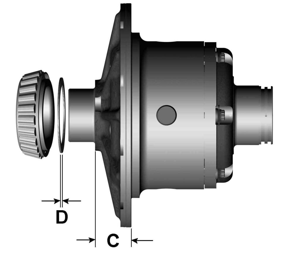
13 3 Bench Measurement Figure 4. Figure 5. 11
14 3 Bench Measurement 3.2 Calculation & Selection of Shims The thickness of the shim pack required for the Air Locker (shown as D in Figure 5.) can now be determined by substituting the measurements taken into the following equation. A + B C = D HINT : If your calculations are correct then the following equation will also be true: A + B C D = ZERO To make a shim pack to match the measurement you calculated as D you can: remove shims from the shim pack you measured as B. add some shims from the shim pack you removed from the right hand side of the original differential to the shim pack you measured as B. supplement your original shims with shims purchased from your vehicle manufacturer. Use a universal shim kit available from most drive train specialists. Never re-use any shims which are damaged or worn. 12

15 4 Installing the Air Locker 4.1 Installing the Carrier Bearings With the Air Locker well supported in an arbor press, apply a thin film of high pressure grease to the ring gear side bearing journal, and assemble the newly established shim pack onto the bearing journal. Press one of the two tapered roller bearing cones onto the bearing journal of the differential carrier until the bearing seats firmly against the shim pack. Never re-use any bearings which are damaged or worn. Invert the Air Locker and apply a thin film of high pressure grease to the seal housing side bearing journal. Press the second bearing cone onto the bearing journal, taking care not to damage the O-ring grooves. (Figure 6.) Figure 6. Do not add any shims between the seal housing bearing and the bearing seat. 13
16 4 Installing the Air Locker 4.2 Mounting the Ring Gear Apply a thin film of high-pressure grease to the ring gear shoulder of the Air Locker to prevent seizing. Thoroughly clean any thread locking compound or other foreign matter from the holes of the ring gear, the threads of the ring gear bolts, and the mating surfaces of the ring gear and the Air Locker flange. Rubbing the ring gear mounting face with a flat oil stone before installation will remove any high spots around the threads. Heat the ring gear to between 80 and 100 C ( F) in an oven or in hot water to slightly expand the gear and facilitate assembly. NEVER HEAT GEARS WITH A FLAME! This could damage the hardened surface of the gear and result in premature wear or failure. Dry the ring gear with compressed air (if wet), paying particular attention to the threaded holes. Install the ring gear onto the Air Locker by aligning the holes in the flange with the tapped holes in the ring gear, then gently tapping it around in a circle with a plastic or copper hammer. Avoid using the bolts to pull down the ring gear as this puts excess strain on the bolts and the differential flange. Apply a thread locking compound to the thread of each ring gear bolt before inserting it. Do not apply threading compound directly into the threaded hole as this could prevent the bolt from reaching its full depth. Tighten the ring gear bolts in a star pattern with a torque wrench according to your vehicle manufacturer s specified torque. 14

17 4 Installing the Air Locker 4.3 Drilling and Tapping the Bulkhead Port A port must be drilled and tapped through the differential housing to allow the seal housing tube through the housing to connect with the air line from the air compressor. Mark a spot for the bulkhead port on the right hand (seal housing) side toward the top of the differential housing that is in an area that will be well clear of the ring gear, the differential, and any other obstructions that may snag the seal housing tube. Cover the drive pinion and axle tube areas with a rag to protect them from metal filings. Figure 7. Drill through the housing square to the outside surface using an 11.2mm [7/16 ] drill. (Fig.7.) Tap the hole from the outside using a ¼ NPT tapered pipe thread tap. Remove any sharp edges from the hole that may chip-off and fall into the housing. Very carefully remove rags and inspect with a service light inside the housing to insure no metal filings are left behind. 15
.")
18 4 Installing the Air Locker 4.4 Assembling the Differential Carrier Relieve all tension on the housing spreader. Place the bearing cup over the bearing cone (Figure 8.). Figure 8. Slide the seal housing into place against the bearing cup (stepped side out). The grooves in the bearing journal under the seal housing, will house the O-rings in the final assembly but they will not be installed now to avoid damage to the O-rings. Install the supplied master shim onto the seal housing. The shim pack cannot be installed at this time as the required thickness (shown as E in Figure 8.) has yet to be determined. 16
19 4 Installing the Air Locker Hold the bearing cup in place on the ring gear side. Holding the master shim and tapered roller bearing cup in place at each end, insert and hold the Air Locker into the differential housing with the seal housing tube pointing straight out of the housing. Install one bearing cap on the ring gear side. The bearing cap on the seal housing side will need to be drilled or slotted as clearance for the seal housing tube. Install the bearing cap bolts finger tight. Push the Air Locker hard across to the ring gear side, and measure the gap (end float) between the master shim and the housing with a feeler gauge. Consult your vehicle manufacturer s service manual to determine the carrier bearing pre-load amount specified for your vehicle. Add the specified pre-load amount to the measurement taken with the feeler gauge to determine a shim amount for E in Figure 8. PRE-LOAD + END FLOAT = SHIM PACK Select suitable shims from the supplied shim kit to make up a shim pack of this thickness. Remove the Air Locker and assemble the shim pack onto the seal housing spigot behind the master shim (Figure 8.). Spread the differential housing again (Refer to section 2.6). If the carrier is too difficult to install with the added shim pack then the spreader tension may need to be increased. Do not spread the housing more than 0.50mm [0.020 ]. Reinstall the Air Locker as before (i.e., with only one bearing cap). Release all spreader tension. 4.5 Approximating the Backlash for Tube Position If the backlash is not close enough to the specified amount, the tube position cannot be accurately measured to modify the bearing cap for tube clearance. This must be checked before hand. 17
20 4 Installing the Air Locker Set a depth indicator on one of the ring gear teeth as in figure 9. While supporting the pinion gear by holding the drive shaft, rotate the differential in both directions while observing the maximum variation in depth from the indicator (i.e., the highest value minus the lowest value). Make sure backlash is less than 0.5mm. This backlash value is for the tube position only and will not be used for final assembly. Figure Re-Shimming the Backlash This step is only necessary when adjusting for incorrect backlash. Reapply the spreader to the differential housing. Remove the bearing cap. Remove the differential. To increase the amount of backlash, reduce the shim thickness D. (Fig. 4.) and increase the shim thickness E (Fig.8.) by the same amount. Reverse this step to decrease the backlash. Remount the differential as before. Release spreader tension. Re-check backlash. 18

21 4 Installing the Air Locker 4.6 Marking the Bearing Cap for Tube Clearance With the Air Locker in place and less than 0.5mm of backlash, an accurate measurement for the seal housing tube clearance can be made. Take time and double check when taking your measurements, as bearing caps are custom fitted to the axle housing and cannot be replaced. With the seal housing tube pointing straight out, measure the distance from a fixed position inside the differential housing to the center of the seal housing tube. (Fig.10.) Figure 10. Record your findings and recheck for accuracy. Remove the bearing cap from the ring gear side of the differential. Remove the Air Locker from the differential housing. Install the seal housing side bearing cap and hand-tighten the bearing cap bolts. It is very important to make sure the punch marks made on the differential housing while removing the differential are matched to the punch marks on the bearing cap. The bearing cap must be replaced exactly as it was removed. (Refer to section 2.4) 19
 Mark the tube position with a center punch where the clearance is to be made for the seal housing tube. Figure 11. Remove the bearing cap from the differential housing.")
22 4 Installing the Air Locker Measure to the bearing cap from exactly the same position on the differential housing that you took the previous measurements from. (Fig.11.) Mark the tube position with a center punch where the clearance is to be made for the seal housing tube. Figure 11. Remove the bearing cap from the differential housing. Measure the distance from the center punch mark made on the bearing cap to the closest edge of the bearing cap. If the center punch mark is greater than 6.35mm [¼ ] from the closest edge of the bearing cap, it is recommended that a small hole be drilled through the bearing cap (Section 4.7.1). If less than 6.35mm [¼ ] from the edge it is recommended that a notch is filed into the side of the bearing cap to avoid break-through while drilling (Section 4.7.2). 20

23 4 Installing the Air Locker 4.7 Modifying the Bearing Cap Drilling the Bearing Cap Hold the bearing cap steady for drilling in a soft jawed vise clamp. Do not apply too much clamping pressure with the vise. The bearing cap may be damaged. Using a pedestal drill, drill a 6.35mm [¼ ] hole through the bearing cap where the seal housing tube hole has been marked. (Fig.12.) Figure 12. Remove the bearing cap from the vise, turn it upside down, and re-clamp it in the vise. The drilled hole must be chamfered approximately 3mm [1/8 ] to remove any sharp edges that may chip-off and fall into the housing. (Fig. 13.) 21

![35mm [¼ ] rat-tailed file.](/docs-images/96/128538519/images/24-3.jpg "File out a notch in the bearing cap from the closest edge until an adequate notch has been cut around the position")
24 4 Installing the Air Locker Figure Notching the Bearing Cap Use a soft jawed vise clamp to hold the bearing cap steady. Using a 6.35mm [¼ ] rat-tailed file. File out a notch in the bearing cap from the closest edge until an adequate notch has been cut around the position of the punch mark. (Fig. 14.). Figure 14. File a chamfer around the inside edge of the notch to remove any sharp edges from the notch that may chip-off and fall into the housing. 22
25 4 Installing the Air Locker 4.8 Final Air Locker Assembly Remove the seal housing, shim pack, and master shim, and clean all parts of the differential assembly. It is very important to make sure the seal housing grooves are free from any contaminants (e.g., water, dirt, metal fillings, etc.) Lubricate the O-rings with oil (prior to assembly), then stretch them over the bearing journal and release them into the grooves. Do not roll the O-rings onto the seal housing as this will damage them. Place the bearing cups onto their respective bearing cones. Install the seal housing over the O-rings by gently applying a downward twisting motion. This will allow the O-rings to gently engage. Ensure that the thrust block has been inserted into the Air Locker if required (section 2.7). Assemble the shim pack and master shim. Point the seal housing tube straight out of the housing, hold the shims and tapered roller bearing cups in place, and insert and hold the Air Locker into the differential housing. Install the bearing cap on the ring gear side. Check to see if the bearing cap on the seal housing side fits over the tube without fouling. Do not forget to check the bearing caps are turned the correct way around. Install all bearing cap bolts and torque to manufacturer s specs. 4.9 Final Backlash Checking Relieve all tension on the housing spreader. Tighten all bearing cap bolts with a torque wrench to the torque specified in your vehicle manufacturer s service manual. Set a depth indicator on one of the ring gear teeth as in Figure
26 4 Installing the Air Locker While supporting the pinion gear by holding the drive shaft, rotate the differential in both directions while observing the maximum variation in depth from the indicator (i.e., the highest value minus the lowest value). This value is referred to as the ring and pinion backlash. Rotate the differential center 90 and measure again for accuracy. Figure 15. Refer to your vehicle service manual for the specified maximum and minimum amounts of backlash. If the backlash is not within the specifications then the differential will have to be removed and reshimmed Re-Shimming the Backlash This step is only necessary when adjusting for incorrect backlash. Reapply the spreader to the differential housing. Remove the bearing caps. Remove the differential. To increase the amount of backlash, reduce the shim thickness D (Fig.5.) and increase the shim thickness E (Fig.8.) by the same amount. Reverse this step to decrease the backlash. Remount the differential as before. Release spreader tension. Check backlash again as before. 24
27 4 Installing the Air Locker 4.10 Profiling the Seal Housing Tube Without using sharp, jagged tools such as pliers (usually your hands are the best tool for this job), bend the seal housing tube so that it closely follows the profile of the differential housing and protrudes through the bulkhead port in the differential housing. (Fig. 16.) Figure 16. Check that the contour of the tube will not interfere with the ring gear, differential, or the cover plate Setting up the Bulkhead Fitting Trim the seal housing tube that is extended outside the differential housing to approximately 20-25mm [ ] of extension using an automotive brake line tubing cutter. Never use a hacksaw for trimming the tube as this will leave metal fillings in the air system. Apply thread sealant to the threads of the bulkhead body. Screw the bulkhead body into the tapped hole, and tighten. 25

28 4 Installing the Air Locker Wipe the area clean of any excess thread sealant (inside and outside of the housing). From the outside of the housing, assemble the small O-ring over the top of the short length of seal housing tube protruding through the bulkhead fitting. While holding the seal housing tube into the bulkhead fitting, insert the small drilled end of the center compression nut over the extended tube as shown in the assembly diagram (Fig.17.), and screw it into the bulkhead body, and lightly tighten. Be sure to insert the correct end of the center compression nut into the bulkhead body. The thread has been partially relieved on the bulkhead side of the center compression nut to visually identify its orientation. (Fig.17.) Figure 17. Excessive tightening of the center compression nut is not necessary to form a good seal around the tube and may damage the O-ring, the seal housing tube, or the threads of the compression nut. 26

29 4 Installing the Air Locker Make sure the seal housing tube is all of the way into the center compression nut while you are tightening it. Again check that no part of the seal housing tube comes in contact with the moving differential components. Less than 8mm [5/16 ] should be considered too little clearance. Gently bend the tube away from moving parts if necessary Bench Testing the Air Locker To test the Air Locker, when 620kPa [90 PSI] shop air is applied to the seal housing tube, the Air Locker should engage. Check all fittings and the seal housing for air leaks. Rotate the differential carrier by turning the pinion flange whilst applying air pressure. An accurate way to test for air leaks is to fit a shut-off valve to an air pressure gauge (ARB part # ALTG01). Once 620 KPA [90 PSI] is reached close the valve, disconnect the air hose, and watch to see if there is any drop in pressure. If so, this will indicate an air leak. (Fig.18.) Figure 18. If a leak is found to be present, spray a soap and water mixture onto the bulkhead air fitting. Bubbles should appear at any leak points. Do not spray this soapy mixture inside the differential. Check that leaky fittings have been adequately tightened. Disassemble, clean threads, and reapply thread sealant if leaking persists. 27
30 4 Installing the Air Locker If a leak is found at the seal housing, carefully remove and refit. Be very careful with the O-rings and check they have not been damaged during installation Reinstalling the Axles Remove the differential housing spreader. Insert both axles fully into the housing and gently tap them inward. Be careful not to damage the axle oil seals with the spline of the axle. Reassemble the brakes, differential and wheels to the vehicle according to your vehicle s service manual. 28
31 5 Installing the Air System 5.1 Mounting the Solenoid Connection to an ARB Air Compressor (Fig.19.) Remove one of the 1/8 BSP plugs from its port in the compressor tank. Apply Teflon paste to the nipple (1/8 X 1/8 BSP) and insert it into the port and tighten. Apply Teflon paste to the free end of the nipple. Assemble the inlet port side of the solenoid (stamped with a 1 ) onto the nipple and tighten. The solenoid should be rotated into a position that does not obstruct any other ports on the compressor tank. The solenoid exhausts compressed air through the center of the black retaining cap when the Air Locker is disengaged. Make sure this orifice cannot be obstructed. Apply Teflon paste to the threads of the 5mm push-in fitting and assemble it into the solenoid outlet port (stamped 2 ) and tighten. ARB Air Compressor Figure
32 5 Installing the Air System Connection to an Alternate Air Source For ease of installation, quality of air supply, and a high level of dependability from your Air Locker(s), ARB strongly recommends use of a genuine ARB Air Compressor, however, the Air Locker air system can be operated on any alternate air source that meets each of the following guidelines: Must supply a minimum of 85PSI [586kPa]. The supply must never exceed 105PSI [724kPa]. The Air source should have a tank capacity that enables it to actuate the Air Locker(s) in one charge so that no hesitation is experienced when locking one or two differentials. HINT : A good way to insure that you have the necessary capacity is to make sure you can engage, disengage, and then reengage your Air Locker(s) without the air source having to regenerate (e.g., without the compressor turning on to refill the tank). Must supply clean air, free of rust, dirt, water, or other foreign matter. Must match the 1/8 BSP porting of the Air Locker solenoid. Mount solenoid within close proximity of the air supply and secure it from the effects of vibration and shock. Connect the air supply to the 1/8 BSP inlet port of the solenoid (stamped 1 on the solenoid body) using thread sealant. IMPORTANT : ARB cannot warrant your Air Locker(s) against damage caused as a result of using an alternate air supply. If you have any doubts as to the suitability of your air system to use in an Air Locker system, consult your ARB distributor. 30
33 5 Installing the Air System 5.2 Running and Securing the Air Line The path taken by the air line from your air source (i.e., compressor) to your Air Locker is unique to your vehicle and the position of your air source. Plan ahead carefully when running the air line and always follow these guidelines: Account for axle travel when running the line from the axle to a fixed point on the vehicle. Leave enough slack in the air line to allow for maximum suspension travel in both directions. Avoid leaving large lengths of air line hanging underneath the vehicle where they may get tangled on rocks, sticks, etc. HINT : Cable tying the air line to one of your flexible brake lines will account for axle travel and should help keep your line from getting snagged. Run the air line all the way from the compressor to the differential before trimming either end of the line to length. This will save complications that may arise if the air line has to be removed. Make sure the line does not contact sharp edges or abrasive surfaces that may damage the air line over time. Do not run the air line around tight bends which may kink the air line and restrict or block the air flow. Keep the air line well away from your vehicle s exhaust components. Air lines will melt if subjected to extreme heat. Do not run more air line than necessary. Excess line volume created when coiling the left over hose, using unusually large diameter hose, etc., will increase drain on the compressor tank resulting in the compressor running more often than needed. Support the air line by tying it back with cable ties wherever possible. At the solenoid end of the air line, trim the line to length with a sharp knife. To remove the air line from the push-in fitting; while holding the flange of the fitting out, push the air line into the fitting as far as possible, then press the flange inward, then pull the air line free of the fitting. 31

34 5 Installing the Air System To attach the air line to the push-in fitting of the solenoid; insert the line firmly into the fitting, pull outward on the flange of the fitting while holding the line as far into the fitting as possible, and then gently pull outward on the air line to clamp the line in place. 5.3 Connection to the Bulkhead Fitting Trim the air line to length using a sharp knife. Insert the support spring over the end of the air line - small end first. (Fig.20.) Insert the outer compression nut over the air line. Insert the 5mm [0.197 ] ferrule over the end of the air line. Leave approx. 5mm of tubing between the ferrule and the end of the tube. Figure 20. Insert the support tube all the way into the end of the air line. 32
35 5 Installing the Air System HINT : If the support tube is too difficult to insert, place the end of the air line into a cup of boiled water to soften the tubing. Insert the tube end all the way into the center compression nut. Screw on the outer compression nut and tighten. The ferrule and support tube are now permanently attached. Assemble the support spring over the outside of the outer compression nut. Secure any loose sections of tube with a cable tie. 33
36 6 Mounting & Connecting the Electrical System 6.1 Mounting the Actuator Switch(es) Air Locker actuator switch(es) can be easily panel mounted inside the vehicle in a 21mm x 36.5mm [0.83 x 1.44 ] rectangular cutout. Only attach the cover plate to the face of the switch once the switch has been mounted and wired correctly as the cover plates are designed to be difficult to remove. For reasons of safety and for ease of operation, the Air Locker actuator switch(es) should be mounted in a location picked to best suit the operator. Make sure you have taken the following points into consideration: Switch(es) MUST be mounted and should never be allowed to simply dangle from the wiring loom during vehicle use. Switch(es) should be within easy reach of the driver. Ideally, any Air Locker switch should be able to be operated without physical effort or distraction to the driver. Switch(es) should be mounted within the line of sight of the driver so that switch position ( ON or OFF ) can be visually determined by the rocker position and the illumination state. The position of the switch(es) should best eliminate any possibility of accidental operation by the driver or one of the passengers. Switch cutout position(s) must be located in an area with a minimum of 50mm [2 ] of clearance behind the face of the cutout. Switch(es) should not be mounted where they will be exposed to water (e.g., in the lower section of an inner door panel). ARB recommends that you apply the Air Locker Warning Sticker (ARB part # ) within close visual proximity of the switch location. If no adequate position can be found on existing dashboard panels, a surface mounted bracket (Fig. 21.) may be purchased from your ARB Air Locker distributor to suit 1, 2, or 3 switches. 34

37 6 Mounting & Connecting the Electrical System Figure Wiring the Actuator System Connection to an ARB Air Compressor When wiring the Air Locker actuator switch(es) and solenoid(s) to an ARB Air Compressor, all connections can easily be set up directly from the supplied wiring loom. (Fig. 22.) Refer to your ARB Air Compressor Installation Guide for details on configuring your installation. 35

38 6 Mounting & Connecting the Electrical System ARB AIR COMPRESSOR WIRING LOOM Figure 22. ARB wiring loom # shown. Consult your ARB Air Compressor Installation Guide for the diagram to suit your compressor model. SWITCH TERMINAL IDENTIFICATION Figure 23. UP 36
39 6 Mounting & Connecting the Electrical System Connection to an Alternate Air Source When connecting the actuation switch to an alternate air source, the switch(es) should be wired according to figures 24. and 25., depending on whether one or two Air Lockers will be installed in the vehicle Single Air Locker System If only one Air Locker is to be installed in the system, the switch and solenoid should be wired according to figure 24. regardless of whether the Air Locker has been installed in the front or rear axle of the vehicle. Attach the appropriate switch cover (i.e., FRONT or REAR ) to the switch. Refer to Figure 23. for the correct switch terminal identification and switch orientation. SINGLE Air Locker SYSTEM Figure
40 6 Mounting & Connecting the Electrical System Dual Air Locker System If two Air Lockers are to be installed in the system, ARB recommends that the switches and solenoids be wired according to figure 25. For safety reasons, this configuration allows SOLENOID 2 to be actuated only if SOLENOID 1 is already on. Attach the REAR AIR LOCKER switch cover to SWITCH 1, and the FRONT AIR LOCKER switch cover to SWITCH 2. Refer to Figure 23. for the correct switch terminal identification and switch orientation. Configure SOLENOID 1 as the air line leading to the rear axle Air Locker, and SOLENOID 2 as the air line leading to the front axle Air Locker. DUAL Air Locker SYSTEM Figure
41 7 Testing & Final Assembly 7.1 Leak Testing With the vehicle parked and the engine off, turn the compressor on and wait until the air system is fully charged. With the Air Locker(s) disengaged, the air source (i.e., compressor) should not have to recharge over time. Intermittent recharging without Air Locker use usually indicates a leak at the solenoid fittings or at the compressor tank O-ring seal. Actuate the Air Locker(s). The compressor should not come on again for a period of at least 15min. Air system recharging within that time period would indicate that a leak is present in the system. If an alternate air source (e.g., an air cylinder or a belt driven air pump) is used instead of a compressor, the air system will have to be leak tested with a pressure gauge and a shut-off valve in series before the solenoid input. If a leak is found to be present, spray a soap and water mixture onto all air fittings in the system while the compressor is fully charged. Bubbles should appear at any leak points. Check that leaky fittings have been adequately tightened. Disassemble, clean threads, and reapply thread sealant if leaking persists. 7.2 Testing the Air Locker Actuation To test that your air system, electrical system, and your Air Locker differential is functioning correctly: Support the vehicle such that the wheels are free to rotate (e.g., on axle stands, a chassis hoist, etc.) Leave the parking brake off, the transmission in neutral, and the Air Locker switch OFF. 39
42 7 Testing & Final Assembly Turn the ignition to the ON position (leaving the motor off). The large illuminating symbol on the Air Locker switch cover should be OFF. Turn the compressor (or alternate air source) on to charge the air supply up to its maximum pressure. Rotate one wheel by hand. The wheel should rotate freely and the opposite wheel should be turning in the opposite direction without any resistance or mechanical noise from within the differential. Turn the Air Locker switch to the ON position. The illuminated symbol on the switch cover should light up. Rotate the same wheel again. Both wheels should rotate together. Turn the switch off again. Rotate the same wheel. The wheels should again rotate in opposite directions. 7.3 Re-Sealing & Filling the Differential Consult the ARB Air Locker Operating & Service Manual for recommendations on differential lubricant specifications. Replace the differential cover using gasket sealant or a new standard differential cover gasket for your make of vehicle. Refill the differential until level with the filler hole. Rotate the differential center 2 full turns. Check the oil level and add oil if necessary. Replace filler plug (apply thread sealant to filler plug before inserting if it is a threaded type plug). Wipe differential housing clean of any oil or grease which may collect dirt or other abrasive particles. 40
43 7 Testing & Final Assembly 7.4 Post-Installation Check List Now that the Air Locker installation has been completed, ARB recommends that you take the time to complete the following check list just to insure that you haven t missed any of the vital steps. The air system has been leak tested. Thread locking compound was used on the ring gear bolts. All torque settings comply with the vehicle manufacturer s specs and were set with an accurate torque wrench. Differential fluid complies with ARB recommendations and has been filled to the correct level. All air lines and wiring have been securely cable tied to resist snagging. Switch(es) have been securely mounted within operator reach, yet well away from danger of accidental engagement. Switch(es) function properly and illuminate to indicate that Air Locker(s) are engaged. All operators who are to use the Air Locker have read, and fully understand the ARB Air Locker Operating & Service Manual. The Air Locker Warning Sticker has been located within close proximity of the actuator switch(es). INSTALLATION PERFORMED BY: DATE OF INSTALLATION: ODOMETER READING: ARB AIR LOCKER SERIAL No: 41
44 7 Testing & Final Assembly 42
45 8 Parts List 8.1 Exploded Assembly Diagram (See itemized parts list overleaf) Figure
46 8 Parts List 8.2 Itemized Parts List (See exploded diagram figure 26.) AIR LOCKER MODEL No. : RD44 ITEM # QTY DESCRIPTION PART # 01 1 FLANGE CAP CLUTCH GEAR DIFFERENTIAL CASE PISTON SPRING CROSS SHAFT RETAINING PIN * 2 CROSS SHAFT RETAINING PIN SHORT CROSS SHAFT SIDE GEAR THRUST WASHER PISTON (Polyamide) BONDED SEAL CYLINDER CAP SEAL HOUSING O-RING CYLINDER CAP RETAINING BOLT TAB WASHER 8mm TAPERED ROLLER BEARING NOT SUPPLIED 15 1 SEAL HOUSING SHIM KIT SHK SPLINED SIDE GEAR PINION THRUST WASHER PINION GEAR SPIDER BLOCK THRUST BLOCK SIDE GEAR * 1 BULKHEAD KIT, O-RING TYPE, 3.5-5mm * 1 PUSH-IN FITTING (5mm to 1/8 BSPP) * 1 AIR LINE (5mm DIA X 6m LONG) * 1 NIPPLE, 1/8 BSP,MALE TO MALE * 1 SOLENOID VALVE * 1 ACTUATOR SWITCH * 1 SWITCH COVER (REAR) * 10 CABLE TIE * 1 WARNING LABEL * 1 BUMPER STICKER * 1 OPERATING & SERVICE MANUAL * 1 INSTALLATION GUIDE * Not illustrated in exploded view. 44
INSTALLATION GUIDE RD149 NISSAN M226,32 SPL. Part No Revision Date 08/08/2008 Copyright 2008 by ARB Corporation Limited
 INSTALLATION GUIDE RD149 NISSAN M226,32 SPL Part No. 2102149 Revision Date 08/08/2008 Copyright 2008 by ARB Corporation Limited No liability is assumed for damages resulting in the use of the information
INSTALLATION GUIDE RD131. TOYOTA 8 IFS, 50mm BRNG. Part No Revision Date 02/10/06 Copyright 2006 by ARB Corporation Limited
 INSTALLATION GUIDE RD131 TOYOTA 8 IFS, 50mm BRNG Part No. 2102131 Revision Date 02/10/06 Copyright 2006 by ARB Corporation Limited No liability is assumed for damages resulting in the use of the information
INSTALLATION GUIDE RD128 LAND ROVER, 24 SPL, BANJO. Part No Revision Date 20/06/2007 Copyright 2007 by ARB Corporation Limited
 INSTALLATION GUIDE RD128 LAND ROVER, 24 SPL, BANJO Part No. 2102128 Revision Date 20/06/2007 Copyright 2007 by ARB Corporation Limited IMPORTANT : BEFORE ATTEMPTING TO DISMANTLE YOUR VEHICLE FOR THIS INSTALLATION,
INSTALLATION GUIDE RD145 ROCKWELL 2.5T, 16 SPL. Part No Revision Date 17/06/08 Copyright 2008 by ARB Corporation Limited
 INSTALLATION GUIDE RD145 ROCKWELL 2.5T, 16 SPL Part No. 2102145 Revision Date 17/06/08 Copyright 2008 by ARB Corporation Limited No liability is assumed for damages resulting in the use of the information
RD180 NISSAN R180A, 27 SPLINE, 3.69 & UP AIR OPERATED LOCKING DIFFERENTIAL INSTALLATION GUIDE
 RD180 NISSAN R180A, 27 SPLINE, 3.69 & UP AIR OPERATED LOCKING DIFFERENTIAL INSTALLATION GUIDE No liability is assumed for damages resulting in the use of the information contained herein. ARB AIR LOCKER
INSTALLATION GUIDE RD114. GM 14 Bolt, 10.5, Full Floating. Part No Revision Date 26/11/04 Copyright 2004 by ARB Corporation Limited
 INSTALLATION GUIDE RD114 GM 14 Bolt, 10.5, Full Floating Part No. 2102114 Revision Date 26/11/04 Copyright 2004 by ARB Corporation Limited 1 Introduction IMPORTANT : BEFORE ATTEMPTING TO DISMANTLE YOUR
INSTALLATION GUIDE RD136 NISSAN H233B, 31 SPL. Part No Revision Date 19/03/2008 Copyright 2008 by ARB Corporation Limited
 INSTALLATION GUIDE RD136 NISSAN H233B, 31 SPL Part No. 2102136 Revision Date 19/03/2008 Copyright 2008 by ARB Corporation Limited No liability is assumed for damages resulting in the use of the information
RD161 DANA 60, SALISBURY, 24 SPLINE, 3.54:1 AIR OPERATED LOCKING DIFFERENTIAL INSTALLATION GUIDE
 RD161 DANA 60, SALISBURY, 24 SPLINE, 3.54:1 AIR OPERATED LOCKING DIFFERENTIAL INSTALLATION GUIDE No liability is assumed for damages resulting in the use of the information contained herein. ARB Air Locker
RD207 SUZUKI JIMNY, FRONT, 22 SPLINE, 8 BOLT RG AIR OPERATED LOCKING DIFFERENTIAL INSTALLATION GUIDE
 RD207 SUZUKI JIMNY, FRONT, 22 SPLINE, 8 BOLT RG AIR OPERATED LOCKING DIFFERENTIAL INSTALLATION GUIDE No liability is assumed for damages resulting in the use of the information contained herein. ARB Air
INSTALLATION GUIDE RD82 FORD 8.8, 28 SPLINE. Part No Revision Date 02/06/06 Copyright 2006 by ARB Corporation Limited
 INSTALLATION GUIDE RD82 FORD 8.8, 28 SPLINE Part No. 210282 Revision Date 02/06/06 Copyright 2006 by ARB Corporation Limited 1 Introduction IMPORTANT : BEFORE ATTEMPTING TO DISMANTLE YOUR VEHICLE FOR THIS
INSTALLATION GUIDE RD93 CHRYSLER 8 1 / 4, 29 SPLINE. Part No Revision Date 15/09/03 Copyright 2001 by ARB Corporation Limited
 INSTALLATION GUIDE RD93 CHRYSLER 8 1 / 4, 29 SPLINE Part No. 210281 Revision Date 15/09/03 Copyright 2001 by ARB Corporation Limited No liability is assumed for damages resulting in the use of the information
RD157 JEEP JK RUBICON, 35 SPLINE AIR OPERATED LOCKING DIFFERENTIAL INSTALLATION GUIDE
 RD157 JEEP JK RUBICON, 35 SPLINE AIR OPERATED LOCKING DIFFERENTIAL INSTALLATION GUIDE No liability is assumed for damages resulting in the use of the information contained herein. ARB Air Locker Air Operated
INSTALLATION GUIDE RD116 DANA 44, 30 SPLINE, 3.92 & UP. Part No Revision Date 25/02/04 Copyright 2004 by ARB Corporation Limited
 INSTALLATION GUIDE RD116 DANA 44, 30 SPLINE, 3.92 & UP Part No. 2102116 Revision Date 25/02/04 Copyright 2004 by ARB Corporation Limited No liability is assumed for damages resulting in the use of the
INSTALLATION GUIDE RD117 DANA 44, 30 SPLINE, 3.73 & DN. Part No Revision Date 25/03/08 Copyright 2007 by ARB Corporation Limited
 INSTALLATION GUIDE RD117 DANA 44, 30 SPLINE, 3.73 & DN Part No. 2102117 Revision Date 25/03/08 Copyright 2007 by ARB Corporation Limited No liability is assumed for damages resulting in the use of the
AIR OPERATED LOCKING DIFFERENTIAL INSTALLATION GUIDE
 DANA 44A, 30 SPLINE AIR OPERATED LOCKING DIFFERENTIAL INSTALLATION GUIDE No liability is assumed for damages resulting in the use of the information contained herein. ARB Air Locker Air Operated Locking
INSTALLATION GUIDE RD90 TOYOYA 7.5, IFS. Part No Revision 06/07/05 Copyright 2002 by ARB Corporation Limited
 INSTALLATION GUIDE RD90 TOYOYA 7.5, IFS Part No. 210290 Revision 06/07/05 Copyright 2002 by ARB Corporation Limited 1 Introduction IMPORTANT : BEFORE ATTEMPTING TO DISMANTLE YOUR VEHICLE FOR THIS INSTALLATION,
HIGH OUTPUT ON-BOARD AIR KIT INSTALLATION GUIDE CKMA12 / 24. Part No. 2102MA12 Revision Date 05/06/07 Copyright 2007 by ARB Corporation Limited
 HIGH OUTPUT ON-BOARD AIR KIT INSTALLATION GUIDE CKMA12 / 24 Part No. 2102MA12 Revision Date 05/06/07 Copyright 2007 by ARB Corporation Limited No liability is assumed for damages resulting in the use of
Zip Locker Installation Instructions
 Zip Locker Installation Instructions PLEASE READ COMPLETELY BEFORE INSTALLATION This installation guide was written to provide the novice and professional with easy guidelines for Zip Locker setup. Over
PPM-D44538RJK JK Rear 5.38 Ring and Pinion Installation Instructions Version 1
 PPM-D44538RJK JK Rear 5.38 Ring and Pinion Installation Instructions Version 1 GENERAL NOTES: Gear set up and installation should be performed by someone experienced in gear and axle set up Special tools
DRIVE AXLE Volvo 960 DESCRIPTION & OPERATION AXLE IDENTIFICATION DRIVE AXLES Volvo Differentials & Axle Shafts
 DRIVE AXLE 1994 Volvo 960 1994 DRIVE AXLES Volvo Differentials & Axle Shafts 960 DESCRIPTION & OPERATION All 960 station wagon models use type 1041 rear axle assembly. All 960 4-door models use type 1045
DRIVE AXLE Nissan 240SX DESCRIPTION & OPERATION AXLE RATIO & IDENTIFICATION AXLE SHAFT & BEARING R & I DRIVE SHAFT R & I
 DRIVE AXLE 1990 Nissan 240SX 1990 DRIVE AXLES Rear Axle - R200 240SX, 300ZX DESCRIPTION & OPERATION The axle assembly is a hypoid type gear with integral carrier housing. The pinion bearing preload adjustment
DISASSEMBLY AND ASSEMBLY
 205-03-1 Front Drive Axle/Differential Ford 8.8-Inch Ring Gear 205-03-1 DISASSEMBLY AND ASSEMBLY Axle Front Drive Special Tool(s) 2-Jaw Puller 205-D072 (D97L-4221-A) Special Tool(s) Carrier Bearing Replacer
REMOVAL & INSTALLATION
 REMOVAL & INSTALLATION AXLE SHAFTS & BEARINGS Removal CAUTION: Failure to turn off air suspension power before raising vehicle may result in unexpected inflation or deflation of air springs. DO NOT reconnect
PROPELLER SHAFT & DIFFERENTIAL CARRIER SECTIONPD CONTENTS
 PROPELLER SHAFT & DIFFERENTIAL CARRIER SECTIONPD CONTENTS PREPARATION...2 PROPELLER SHAFT...5 On-Vehicle Service...6 Removal and Installation...7 Inspection...7 Disassembly...7 Assembly...8 ON-VEHICLE
Steer Axles. Spicer. Service Manual. AXSM-0070 November Front Drive Steer Axle Model 60
 Spicer Steer Axles Service Manual AXSM-0070 November 2017 Front Drive Steer Axle Model 60 General Information The description and specifications contained in this service publication are current at the
Mustang Differential Gears - Installation Instructions
 Mustang Differential Gears - Installation Instructions The below installation instructions work for the following products: Ford Racing Gears - 3.73 Gears for 8.8" Ford Rear End Ford Racing Gears - FRPP
Installation Instructions
 Preparing your vehicle to install your brake system upgrade 1. Rack the vehicle. 2. If you don t have a rack, then you must take extra safety precautions. 3. Choose a firmly packed and level ground to
1999 F-150/250 Workshop Manual
 Page 1 of 30 SECTION 205-03: Front Drive Axle/Differential Ford 8.8-Inch Ring Gear 1999 F-150/250 Workshop Manual DISASSEMBLY AND ASSEMBLY Procedure revision date: 01/08/2003 Axle Front Drive Special Tool(s)
Amarillo PUMP DRIVES (250 HP THROUGH 350 HP) INSTRUCTIONS FOR REPAIRING MODELS 250, 300, and 350
 INSTRUCTIONS FOR REPAIRING MODELS 250, 300, and 350") Amarillo PUMP DRIVES (250 HP THROUGH 350 HP) INSTRUCTIONS FOR REPAIRING MODELS 250, 300, and 350 Amarillo Right Angle Pump Drives, if properly installed and maintained, should provide years of service
Amarillo PUMP DRIVES (250 HP THROUGH 350 HP) INSTRUCTIONS FOR REPAIRING MODELS 250, 300, and 350 Amarillo Right Angle Pump Drives, if properly installed and maintained, should provide years of service
Maintenance Instructions
 General Note These instructions contain information common to more than one model of Bevel Gear Drive. To simplify reading, similar models have been grouped as follows: GROUP 1 Models 11, 0, 1,, (illustrated),,
CKMTA12 / 24 INSTALLATION GUIDE MAXIMUM PERFORMANCE ON-BOARD AIR SUPPLY
 MAXIMUM PERFORMANCE ON-BOARD AIR SUPPLY INSTALLATION GUIDE CKMTA12 / 24 Part No. 2102MTA12 Revision Date 2/07/2014 Copyright 2013 by ARB Corporation Limited No liability is assumed for damages resulting
DIFFERENTIALS & AXLE SHAFTS
 DIFFERENTIALS & AXLE SHAFTS 2001 Chevrolet Camaro 2000-01 DRIVE AXLES General Motors Differentials & Axle Shafts Chevrolet; Camaro Pontiac; Firebird DESCRIPTION & OPERATION Drive axle is a semi-floating,
Ford 9 XD Aussie-Locker Install Instructions.
 Ford 9 XD-45831 Aussie-Locker Install Instructions. Before the install check the following. 1. Must be 31 spline 4-pinion carrier. 2. Must be an open carrier not a limited slip. 3. Refer to Ford or vehicle
Maintenance Information
 45528270 Edition 1 June 2007 Barring Motor T480 Series Maintenance Information Save These Instructions WARNING Always wear eye protection when operating or performing maintenance on this Barring Motor.
TC20 Chain Driven Power Take-Off Overhaul Instructions
 TC20 Chain Driven Power Take-Off Overhaul Instructions Table of Contents Section Page Introduction 4 Ordering Repair Parts 4 General Information 5 Special Tools 6 Disassembly See Page 2 Reassembly See
AEV30308AA Last Updated: 05/31/18. 4 DUALSPORT sc SUSPENSION system for RAM 1500 air ride standard and rebel INSTALLATION GUIDE
 AEV30308AA Last Updated: 05/31/18 4 DUALSPORT sc SUSPENSION system for RAM 1500 air ride standard and rebel INSTALLATION GUIDE PLEASE READ BEFORE YOU START TO GUARANTEE A QUALITY INSTALLATION, WE RECOMMEND
A/C COMPRESSOR SERVICING Article Text 1991 Saab 9000 For Copyright 1997 Mitchell International Friday, October 15, :22PM
 Article Text ARTICLE BEGINNING 1991 GENERAL SERVICING Compressor Service * PLEASE READ THIS FIRST * CAUTION: When discharging air conditioning system, use only approved refrigerant recovery/recycling equipment.
Valtek Auxiliary Handwheels and Limit Stops
 Valtek Auxiliary s and Limit Stops Table of Contents Page 1 General information 2 Installation 2 Side-mounted handwheels, size 25 and 50 (linear actuators) 3 Side-mounted handwheels, size 100 and 200 (linear
Maintenance Information
 80234313 Edition 1 June 2006 Air Grinder, Die Grinder, Sander and Belt Sander Series G1 (Angle) Maintenance Information Save These Instructions WARNING Always wear eye protection when operating or performing
Installation Instructions Z-Gate Shifter
 Installation Instructions Z-Gate Shifter Part Number 80681 1998, 2001 by B&M Racing and Performance Products The B&M Z-Gate shifter can be used in vehicles equipped with most popular three speed automatic
Maintenance Information
 04581245 Edition 2 May 2014 Air Grinder, Die Grinder and Sander Series G2 (Angle) Maintenance Information Save These Instructions Product Safety Information WARNING Failure to observe the following warnings,
Service Manual Air Tech Second Stage
 Service Manual Air Tech Second Stage Copyright 2002, Cressi-sub Revised 3/2002 2 Air Tech Second Stage Service Manual Contents BEFORE STARTING... 3 DISASSEMBLY... 3 PARTS CLEANING AND LUBRICATION... 9
AMARILLO PUMP DRIVES MODEL 1 OOOA, 1200, 1500, 1800
 AMARILLO PUMP DRIVES MODEL 1 OOOA, 1200, 1500, 1800 INSTRUCTIONS FOR REPAIRING MARCH 1, 1993 AMARILLO GEAR COMPANY Post Office Box 1789, Amarillo, Texas 79105 806 / 622-1273 FAX 806 / 622-3258 INSTRUCTIONS
SERVICE MANUAL L130B / L4130 Series Logstacker Drive Axle With Bolt-On Stub End Retainer
 SERVICE MANUAL L130B / L4130 Series Logstacker Drive Axle With Bolt-On Stub End Retainer Page 1 Allied Form #80-930 Rev 07/2009 SERVICE MANUAL LOG STACKER DA202 DRIVE AXLE TABLE OF CONTENTS PROCEDURE FOR
SISU DP-330 DRIVE GEAR. Maintenance Manual
 SISU DP-330 DRIVE GEAR Maintenance Manual Sisu Axles, Inc. Autotehtaantie 1 PO Box 189 Fin-13101 Hameenlinna Finland Phone +358 204 55 2999 Fax +358 204 55 2900 DP330DG.PDF (3/2007) TABLE OF CONTENTS
TROUBLESHOOTING SPECIAL TOOL ASSEMBLY AND ADJUSTMENT
 1 INDEX Models FD, FE, FF and SG REAR AXLE 10-1 10-108E-07 CHAPTER 10 REAR AXLE Models FD, FE, FF and SG TROUBLESHOOTING...10-2 10 SPECIAL TOOL...10-3 WHEEL HUB AND RELATED PARTS DISASSEMBLY...10-7 INSPECTION...10-9
LIMITED SLIP DIFFERENTIAL INSTALLATION
 Installation of the limited slip gear can be done with axle out of car or with car lifted to gain access from underneath. Refer to repair manual for proper lifting instructions if car is to be lifted.
This file is available for free download at
 This file is available for free download at http://www.iluvmyrx7.com This file is fully text-searchable select Edit and Find and type in what you re looking for. This file is intended more for online viewing
 DRUM BRAKE RIMS Periodic inspection of drum brake rims is necessary to determine indications of uneven or excessive wear. In general, brake rim failures other that regular wear are caused by brake linings
2005 Toyota RAV AUTOMATIC TRANSMISSIONS U240E & U241E Overhaul
 2001-05 AUTOMATIC TRANSMISSIONS U240E & U241E Overhaul APPLICATION CAUTION: Flush oil cooler and oil cooler lines prior to transaxle installation. Oil cooling system contamination may cause premature transaxle
INSTALLATION INSTRUCTIONS 88029
 INSTALLATION INSTRUCTIONS 88029 FOR SUSPENSION SYSTEMS RS6503: JEEP WRANGLER (TJ) READ ALL INSTRUCTIONS THOROUGHLY FROM START TO FINISH BEFORE BEGINNING INSTALLATION REV F IMPORTANT NOTES! WARNING: This
1984 Dodge W250 PICKUP
 1984 Dodge W250 PICKUP Submodel: Engine Type: V8 Liters: 5.2 Fuel Delivery: CARB Fuel: GAS Dana 44 MODELS THROUGH 1984 2. Raise and safely support the vehicle, then remove the wheel hub and bearings as
ONYX VALVE CO MODEL CAR, CAP-PFO Installation & Maintenance
 ONYX VALVE CO MODEL CAR, CAP-PFO Installation & Maintenance OPERATION: (4-2010) The Onyx series CAR-PFO and CAP-PFO pinch valves fail open on loss of air. The simple spring and air bag arrangement drives
Maintenance Information
 80234313 Edition 2 May 2014 Air Grinder, Die Grinder, Sander and Belt Sander Series G1 (Angle) Maintenance Information Save These Instructions Product Safety Information WARNING Failure to observe the
DeZURIK " BAW AWWA BUTTERFLY VALVES WITH EPOXY-RETAINED SEAT
 DeZURIK 20 144" BAW AWWA BUTTERFLY VALVES WITH EPOXY-RETAINED SEAT Instruction D10373 April 2017 Instructions These instructions provide information about the 20 (250 F2 model only) and the 24-144 BAW
OPERATION AND PARTS MANUAL
 OPERATION AND PARTS MANUAL MODEL NUMBER : PART NUMBER : GTL 1110 1900-0510 SERIAL NUMBER : BAYNE MACHINE WORKS, INC. PHONE: (864) 288-3877 910 FORK SHOALS ROAD TOLL FREE: (800) 535-2671 GREENVILLE S.C.,
INSTALLATION MANUAL. TORQ Locker TL GM 14 Bolt Installation Instructions. Made in USA By: Page 1 of 8
 INSTALLATION MANUAL TORQ Locker TL-19035 GM 14 Bolt Installation Instructions Made in USA By: Page 1 of 8 Page 2 of 8 INSTALLATION MANUAL TORQ Locker TL-19035 GM 14 Bolt Installation Instructions By: INTRODUCTION
2.2L 4-CYL - VIN [S]
![2.2L 4-CYL - VIN [S]](/thumbs/72/67564355.jpg "2.2L 4-CYL - VIN [S]") 2.2L 4-CYL - VIN [S] 1994 Toyota Celica 1994 ENGINES Toyota 2.2L 4-Cylinder Celica NOTE: For repair procedures not covered in this article, see ENGINE OVERHAUL PROCEDURES - GENERAL INFORMATION article
2.2L 4-CYL - VIN [S] 1994 Toyota Celica 1994 ENGINES Toyota 2.2L 4-Cylinder Celica NOTE: For repair procedures not covered in this article, see ENGINE OVERHAUL PROCEDURES - GENERAL INFORMATION article
LOW PRESSURE BALANCED VALVE DIAPHRAGM BALANCED
 DIAPHRAGM BALANCED All Rights Reserved. All contents of this publication including illustrations are believed to be reliable. And while efforts have been made to ensure their accuracy, they are not to
ONYX VALVE CO MODEL DAC-PFO Installation & Maintenance
 ONYX VALVE CO MODEL DAC-PFO Installation & Maintenance OPERATION: (01-10) The Onyx series DAC-PFO pinch valve fails open on loss of air. This simple spring and air bag arrangement that drives a pair of
INSTALLATION INSTRUCTIONS
 INSTALLATION INSTRUCTIONS DISC BRAKE CONVERSION KITS A121-1, A121-2, A121-3, A121-4 1967-69 Ford & Mercury Thank you for choosing STAINLESS STEEL BRAKES CORPORATION for your braking needs. Pleases take
Maintenance Information
 16573370 Edition 2 February 2014 Air Grinder 99V Series Maintenance Information Save These Instructions Product Safety Information WARNING Failure to observe the following warnings, and to avoid these
SECTION Front Drive Axle/Differential
 205-03-i Front Drive Axle/Differential 205-03-i SECTION 205-03 Front Drive Axle/Differential CONTENTS PAGE Axle... 205-03-2 205-03-2 Front Drive Axle/Differential 205-03-2 Axle Special Tool(s) C-Frame
INTEGRAL POWER STEERING GEAR FORD Applies to F-100 F-350 (4X2), F-150 F-250 (4X4) And Bronco
, F-150 F-250 (4X4) And Bronco") Rockcrawler Steering Shop Manual page1 The following is from the Ford 1978 Truck Shop Manual, Volume 1 Chassis. It is provided here as a courtesy to classic Ford owners who would like to perform their
Rockcrawler Steering Shop Manual page1 The following is from the Ford 1978 Truck Shop Manual, Volume 1 Chassis. It is provided here as a courtesy to classic Ford owners who would like to perform their
'99-03 CHEVROLET/GMC IFS 4WD 6" SUSPENSION SYSTEM P/N INSTALLATION INSTRUCTIONS
 1/16/04 '99-03 CHEVROLET/GMC IFS 4WD 6" SUSPENSION SYSTEM P/N. 10-41099 INSTALLATION INSTRUCTIONS NOTE: Each Lift Kit and options to Lift Kits are packaged separately. Therefore, installation procedures
INSTALLATION INSTRUCTIONS
 INSTALLATION INSTRUCTIONS INSTALLATION INSTRUCTIONS FOR A136 REAR DRUM TO DISC BRAKE CONVERSION KIT for 1970-75 Jeep, CJ SERIES with Dana 44 flanged axle Thank you for choosing STAINLESS STEEL BRAKES CORPORATION
Sachs shock manual. ( ) 2 & 4 Stroke RR Enduro. ( ) RS Dual Sport
 2 & 4 Stroke RR Enduro. ( ) RS Dual Sport") Sachs shock manual (2013 2015) 2 & 4 Stroke RR Enduro (2014-2015) RS Dual Sport 1 Introduction The procedures in this manual must take place in a clean environment using professional tools and some specific,
Sachs shock manual (2013 2015) 2 & 4 Stroke RR Enduro (2014-2015) RS Dual Sport 1 Introduction The procedures in this manual must take place in a clean environment using professional tools and some specific,
INSTALLATION INSTRUCTIONS
 INSTALLATION INSTRUCTIONS REAR DISC CONVERSION KIT A128 1990-1995 JEEP WRANGLER (YJ) WITH DANA 35 AXLES (non-abs) Thank you for choosing STAINLESS STEEL BRAKES CORPORATION for your braking needs. Pleases
Z-Gate Universal Shifter
 Installation Instructions Z-Gate Universal Shifter Fits: GM, Ford, Lincoln and Chrysler Transmissions See Application Guide for Specific Applications Part #80681 Rev 06/01/2018 WORK SAFELY! For maximum
Transaxle. 1. Mount the transaxle to Bench Mounted Holding Fixture T57L-500-B.
 «1997 Aspire Table of Contents» «Group 07: TRANSAXLE» «Section 07-01: Transaxle, Automatic» «DISASSEMBLY» Transaxle CAUTION: To prevent dirt from entering the transaxle, it should be disassembled and kept
INSTALLATION INSTRUCTIONS
 INSTALLATION INSTRUCTIONS REAR DISC BRAKE CONVERSION KITS A112, A112-1 & A112-93 1979-93 FORD MUSTANG with 7.5" & 8.8" AXLES Thank you for choosing STAINLESS STEEL BRAKES CORPORATION for your braking needs.
BMK-18 U.S. Patent #5,298,158
 BMK- U.S. Patent #5,29,5 Marine Dual Remote Filtration System Mounting Kit Installation and Servicing Instructions IMPORTANT NOTICE Read all instructions completely before attempting to install this unit.
INSTALLATION INSTRUCTIONS
 INSTALLATION INSTRUCTIONS PERFORMANCE AT THE WHEELS KIT W120-22, W120-23 1964 1/2-69 MUSTANG Thank you for choosing STAINLESS STEEL BRAKES CORPORATION for your braking needs. Pleases take the time to read
OPERATION AND PARTS MANUAL
 OPERATION AND PARTS MANUAL MODEL NUMBER : PART NUMBER : GRL 1110 1900-0540 SERIAL NUMBER : BAYNE MACHINE WORKS, INC. PHONE: 864.288.3877 910 FORK SHOALS ROAD TOLL FREE: 800.535.2671 GREENVILLE SC, 29605
DYNATRAC PRODUCTS V5.3
 DYNATRAC PRODUCTS V5.3 2000-2008 Dodge Hub Kit Stage 1 4x4, Front Axle Free Spin Conversion Kit Note: This Kit is not Approved for 2007 & up 3500 Cab and Chassis Trucks Due to a Larger U-Joint (If U-Joint
LAND ROVER 90, 110 AND ONWARDS WARNING
 Product Description: Suited to vehicle/s: Winch Fitting Kit: Fitting Kit: 6172941 3432300 WINCH BULL BAR 3932400 WINCH BUMPER BAR LAND ROVER 90, 110 AND 130-1985 ONWARDS 3532070 (OPTIONAL EXTRA) WARNING
 Page 1 of 15 Transmission, Model S5-42 ZF Model S5-42 ZF Disassembly NOTE: For 4x4 and F-Super Duty vehicles, skip to Step 5. 1. Attach the transmission to the Bench Mounted Holding Fixture T57L-500-B
WARNING. When installed in accordance with these instructions, the front protection bar does not affect operation of the SRS airbag.
 Part Number: 3400 Product ARB WINCH BULL BAR Description: Suited to TOYOTA 4 RUNNER YEAR MODELS 03 ON vehicle/s: WARNING REGARDING VEHICLES EQUIPPED WITH SRS AIRBAG: When installed in accordance with these
DRIVE AXLE - INTEGRAL HOUSING
 DRIVE AXLE - INTEGRAL HOUSING 1993 Toyota Celica 1993 DRIVE AXLES Toyota Differentials & Axle Shafts - Integral Housing Toyota; Celica All-Trac DESCRIPTION Drive axle assembly is a hypoid type with integral
Installation Instructions
 Parts Installation Instructions DESCRIPTION PART # QTY A Alignment Tab PN ESB101 1 B Drill Guide PN ESB102 1 C Actuator Cable Assembly PN ESB103 1 C1 72 Actuator Cable 1 C2 5/16 Jam Nut 1 C3 Star Washer
MGM Brakes Service Manual
 MGM Brakes Service Manual MAGNUM Performance Plus Spring Brake Actuators (MJ-Series 3.00 / 76mm Long Stroke ) For: S-Cam Tamper-Resistant MAGNUM Performance Plus Spring Brake Actuators Figure 1 A B C Your
CHRYSLER WRANGLER JK JEEP 2006 ON WARNING. ARB 4x4 ACCESSORIES. Corporate Head Office
 Part Number: 3450210 F/KIT: 6172210 Product Description: JEEP ROCK CRAWLER BAR Suited to vehicle/s: CHRYSLER WRANGLER JK JEEP 2006 ON WARNING This product must be installed exactly as per these instructions
WARNING: Only perform this installation if you are experienced, fully equipped mechanic.
 DYNATRAC V3.2 2005-Present Ford Super Duty 250/350-4x4, Front Axle, Free Spin Conversion Kit Some of the less common tools, which will be required: 6 point Spanner socket (OTC #7090-A or equivalent). These
Disassembly and Assembly
 K EN R 623 2-00 August 2006 Disassembly and Assembly 2506-15 Industrial Engine M G A (Engine) MGB (Engine) M G D (Engine) Important Safety Information Most accidents that involve product operation, maintenance
WARNING. When installed in accordance with these instructions, the front protection bar does not affect operation of the SRS airbag.
 Part Number: 346400 F/Kit 6774 Product ARB WINCH BULL BAR Description: Suited to NISSAN TITAN YEAR MODELS 04 to 07 vehicle/s: WARNING REGARDING VEHICLES EQUIPPED WITH SRS AIRBAG: When installed in accordance
Brake System H TX, H2.0TXS [B475]; H TX [B466] Safety Precautions Maintenance and Repair
![Brake System H TX, H2.0TXS [B475]; H TX [B466] Safety Precautions Maintenance and Repair](/thumbs/86/93834005.jpg "Brake System H TX, H2.0TXS [B475]; H TX [B466] Safety Precautions Maintenance and Repair") HMM180001 Brake System H1.5-1.8TX, H2.0TXS [B475]; H2.5-3.5TX [B466] Safety Precautions Maintenance and Repair When lifting parts or assemblies, make sure all slings, chains, or cables are correctly fastened,
HMM180001 Brake System H1.5-1.8TX, H2.0TXS [B475]; H2.5-3.5TX [B466] Safety Precautions Maintenance and Repair When lifting parts or assemblies, make sure all slings, chains, or cables are correctly fastened,
13. CRANKCASE/CRANKSHAFT/BALANCER/PISTON/CYLINDER
 13. CRANKCASE/CRANKSHAFT/BALANCER/PISTON/CYLINDER COMPONENT LOCATION 13-2 SERVICE INFORMATION 13-3 TROUBLESHOOTING 13-4 CRANKCASE SEPARATION 13-5 CRANKSHAFT 13-7 MAIN JOURNAL BEARING 13-9 CRANKPIN BEARING
Maintenance Information
 16572679 Edition 2 May 2014 Air Drill QP Series Maintenance Information Save These Instructions Product Safety Information WARNING Failure to observe the following warnings, and to avoid these potentially
WARNING. When installed in accordance with these instructions, the front protection bar does not affect operation of the SRS airbag.
 Part Number: 34000 Product Description: Suited to vehicle/s: ARB WINCH BULL BAR TOYOTA FJ CRUISER WARNING REGARDING VEHICLES EQUIPPED WITH SRS AIRBAG: When installed in accordance with these instructions,
TO INDEX DIFFERENTIAL FRONT DIFFERENTIAL CARRIER OIL SEAL (4WD) FRONT DIFFERENTIAL CARRIER ASSEMBLY (4WD) REAR DIFFERENTIAL CARRIER OIL SEAL
 FRONT DIFFERENTIAL CARRIER ASSEMBLY (4WD) REAR DIFFERENTIAL CARRIER OIL SEAL") TO INDEX DRIVE LINE / AXLE DIFFERENTIAL DIFFERENTIAL SYSTEM PRECAUTIONS.............................................. OPERATION CHECK......................................... PROBLEM SYMPTOMS TABLE.................................
TO INDEX DRIVE LINE / AXLE DIFFERENTIAL DIFFERENTIAL SYSTEM PRECAUTIONS.............................................. OPERATION CHECK......................................... PROBLEM SYMPTOMS TABLE.................................
LEXUS IS 250 Front Performance Brake Kit Section I - Installation Preparation
 LEXUS IS 250 Front 2006- Performance Brake Kit Section I - Installation Preparation Part Number: PTR09-53080 Kit Contents Item # Quantity Reqd. Description 1 1 Brake Rotor, LH Front 2 1 Brake Rotor, RH
Disassembly and Assembly
 SENR9973-01 September 2007 Disassembly and Assembly 400C Industrial Engine HB (Engine) HD (Engine) HH (Engine) HL (Engine) HM (Engine) HN (Engine) HP (Engine) HR (Engine) Important Safety Information Most
ONYX VALVE CO MODEL DAO-PFO Installation & Maintenance
 ONYX VALVE CO MODEL DAO-PFO Installation & Maintenance OPERATION: (4-2010) The Onyx DAO-PFO pinch valve is an open frame valve without housing enclosure and fails open on loss of air. The actuator drives
FRONT AXLE - 9 1/4 AA
 DR FRONT AXLE - 9 1/4 AA 3-45 FRONT AXLE - 9 1/4 AA TABLE OF CONTENTS page FRONT AXLE - 9 1/4 AA DESCRIPTION......................... 45 OPERATION........................... 45 DIAGNOSIS AND TESTING................
INSTALLATION INSTRUCTIONS
 INSTALLATION INSTRUCTIONS REAR DISC BRAKE CONVERSION KIT A125-2 1955-70 FULL SIZE CHEVROLET Thank you for choosing STAINLESS STEEL BRAKES CORPORATION for your braking needs. Pleases take the time to read
Maintenance Information
 16573347 Edition 2 February 2014 Air Grinder Series 88H Maintenance Information Save These Instructions Product Safety Information WARNING Failure to observe the following warnings, and to avoid these
18SP680Rev3 EPA04 MBE 4000 Car Hauler Low Pressure Fuel Lines
 8SP680Rev3 EPA04 MBE 4000 Car Hauler Low Pressure Fuel Lines KIT DESCRIPTION These service kits include all necessary parts to replace the low pressure fuel lines between the fuel filter housing and fuel
ONYX VALVE CO MODEL DAO-ADA Installation & Maintenance
 ONYX VALVE CO MODEL DAO-ADA Installation & Maintenance OPERATION: (4-2010) The Onyx DAO-ADA pinch valve is an open frame valve without housing enclosure and fails last position on loss of air. This actuator
GP113S STAINLESS HEADER WITH STAINLESS Y-PIPE
 GP113S STAINLESS HEADER WITH STAINLESS Y-PIPE HAS NO AIR FITTING AT THE FRONT OF EACH MANIFOLD FOR CHEVROLET/GMC 96-00 PICKUP 7.4L 2/4WD 96-00 SUBURBAN 7.4L 2/4WD GIBSON HEADERS ARE 50 STATE SMOG LEGAL
Operation and Maintenance Instructions
 Hydratight Limited Bentley Road South Darlaston West Midlands WS10 8LQ United Kingdom Tel: +44 121 50 50 600 Fax: +44 121 50 50 800 E-mail: enquiry@hydratight.com Website: www.hydratight.com HNOFC062490400