Model Number Part Number (Order) Description. PATP Ram PATP-9400-P Hydraulic Pump PATP-HT Hose Tube Assembly
|
|
|
- Hubert Morgan
- 5 years ago
- Views:
Transcription

1 Operating & Service Manual IM 05/11/2011 Airetool PATP Series Pneumatic/Hydraulic Tube Puller Model Number Part Number (Order) Description PATP Ram PATP-9400-P Hydraulic Pump PATP-HT Hose Tube Assembly For additional product information visit our website at
2 Safety Recommendations WARNING: FOR YOUR SAFETY AND THE SAFETY OF OTHERS, READ AND UNDERSTAND THE SAFETY REC- OMMENDATIONS AND OPERATING INSTRUCTIONS BE- FORE USING THIS TOOL. 1. KNOW YOUR POWER TOOL Read your operating and service manual carefully. Learn its applications and limitations as well as the specific potential hazards particular to this tool. 2. DISCONNECT TOOLS when not in use, before servicing, when changing accessories such as grippers and draw rods, etc. 3. AVOID AGAINST ACCIDENTAL STARTING Do not carry the tool with your finger on the switch. Be sure the shut off valve is in the off position before connecting the air supply to this tool. 4. KEEP HANDS AWAY FROM ALL MOVING PARTS. 5. STAY ALERT Watch what you are doing and use common sense. 6. ALWAYS WEAR PROTECTIVE EQUIPMENT: Hearing protectors are required in high noise areas, 85dBA or greater. The operation of tools and equipment in the area, reflective surfaces, process noises and non-resonant structures can substantially contribute to and increase the noise level in the area. For additional information on hearing protection, refer to Federal OSHA Regulations section Occupational Noise Exposure, and the American National Standards Institute, ANSI S12.6 Hearing Protectors. Some individuals are susceptible to disorders of the hands and arms when exposed to task which involve highly repetitive motions or vibration. Those individuals predisposed to vasculatory or circulation problems may be particularly susceptible. Cumulative trauma disorders such as carpal tunnel syndrome and tendonitis can be caused by repetitions, forceful exertions of the hands and arms. These disorders develop gradually over periods of weeks, months, and years. For additional information on eye and face protection, refer to Federal OSHA Regulations, 29 Code of federal regulations, Section eye and Face Protection, and American National Standards Institute, ANSI A87.1, Occupational and Educational Eye and Face Protection Z87.1 is available from the American National Standards Institute, 1430 Broadway Avenue, New York, NY Tasks should be performed in such a manner that the wrists are maintained in a neutral position which is not flexed, hyperextended, or turned side to side. Stressful postures should be avoided and can be controlled through tool selection and work location. Page - 2
3 Any user suffering from prolonged symptoms of tingling, numbness, clumsiness or weakened grip, nocturnal pain in the hand or any other disorder of the shoulders, arms, wrists, or fingers is advised to consult with a physician. If it is determined that the symptoms are job related or aggravated by movements and postures dictated by the job design it may be necessary for the employer to take steps to prevent further occurrences. These steps might include, but are not limited to repositioning the workpiece or redesigning the work station, reassigning workers to other jobs, rotating jobs, altering work pace, and / or changing the type of tool used so as to minimize stress on the operator. Some task may require more than one type of tool to obtain the optimum operator/tool/task relationship. The following recommendations will help reduce or moderate the effects of repetitive work motions and/or extended vibration exposure. Use a minimum hand grip force consistent with proper control and safe operation. Keep wrist as straight as possible. Keep body and hands warm and dry. Avoid anything that inhibits blood circulation - Smoking tobacco - Cold temperatures - Certain drugs Avoid highly repetitive movements of hands and wrist, and continuous vibration exposure. Follow good machine shop practices. Rotating shafts and moving components can entangle and entrap, and can result in serious injuries. Never wear long hair, loose fitting clothes, gloves, ties, or jewelry when working with or near the equipment. Use of this tool may produce hazardous fumes, particles and/or dust form the tube or vessel they are being extracted from. To avoid adverse health effects utilize adequate ventilation and/or a respirator. Read the material safety data sheet of any fluids or other materials involved in the tube removal process. Page - 3
4


5 Model PATP-9000 Hydraulic Tube Puller Tube Pulling System Complete Consists Of : 1. PATP 9000 Ram Assembly PATP 9400 P Hydraulic Pump Unit PATP HT Hose-Tube Assembly ATP 9022 XXX Gripper Kit ( XXX See Chart On Page 14 ) Page - 5
6 OPERATING & SERVICE INSTRUCTIONS FOR Model PATP-9000 TUBE PULLER THIS SYSTEM IS CAPABLE OF GENERATING 13 3/4 TONS OF FORCE AT 10,000 PSI, THEREFORE, DO NOT OPERATE THIS SYSTEM BEFORE FULLY READING AND UNDERSTANDING THE SET-UP AND OPERATING INSTRUCTIONS. ALWAYS WEAR EYE PROTECTION WHEN USING THIS EQUIPMENT. BEFORE STARTING THE PUMP UNIT 1) To avoid possible serious injury to personnel or equipment, always post DANGER SIGNS (Part. No ) and insure that the area directly behind the tube sheet/ bundle is kept clear and that a suitable barrier is in use while using the puller. If a draw rod should break while pulling tube stubs or tubes, the draw rod tip, cam and expansion nut can be propelled out into this area with considerable force. 2) Make sure the vented filler cap/fill gauge is installed. 3) Check oil level (see pump manual # IM). 4) Check hose for leaks, cuts, abrasions or bulges read and fully understand the warning tags attached to the hose assemblies. Check hose s label and fittings for underrated replacement parts. NEVER operate with damaged hoses and/or cords. NEVER allow hoses and/or cords to kink or knot. NEVER place hoses in an area where they may be stepped on or run over by any type of vehicle, cart, hand truck, etc. NEVER connect any hydraulic fitting, hose or device to the hydraulic portion of the pump that does not carry a 10,000 psi rating. 5) Make sure all hose and control tube connections are fully coupled. 6) Check air supply for sufficient capacity (see pump unit nameplate). Note: A ½ ID x 10 long supply hose is recommended. If a longer hose is required, ¾ ID or larger will provide best performance. The use of quick disconnects will decrease performance unless they are sufficiently oversized or of an unrestricted flow type. GRIPPER SELECTION: Grippers are sized for nominal ID/OD brass tubes rolled with normal wall reduction in tube sheet holes with normal clearance. Tubes with smaller than normal rolled ID s may require the use of a smaller gripper for smooth release of the tube after pulling. Tubes with larger ID s may require the use of a larger gripper to avoid the excessive bending of the gripper and prolong gripper life. For determining the most suitable gripper, it is recommended that the tube s rolled section be measured with an AIRETOOL Tube Gage. See Gripper Selection chart on Page 14. DRAW ROD-EXPANSION NUT- LOCK NUT SELECTION: These three components must match the gripper chosen (if necessary a second expansion nut may be used instead of a lock nut). See Gripper Selection chart on Page 14. NOSE BUSHING SELECTION: The bushing ID must be large enough to clear the tube OD (including flared or belled ends), and the bushing OD must be small enough so that it does not interfere with adjacent tubes protruding from the tube sheet. Standard nose bushings accommodate tubes that have not been flared or belled. NOTE: It may be necessary in some applications where the tubes are brittle and/or if the grippers are positioned over tube sheet serrations (grooves), to shorten the nose bushing to allow the grippers to seat further into the tube sheet. Care must be taken that the cut be smooth and square to avoid gripper breakage. Since the bushing is casehardened, a lathe with carbide tooling is recommended. Standard Nose Bushing sizes: SIZE I.D. O. D. 5/8 11/16 29/64 3/4 7/8 11/8 7/8 31/32 111/ /16 1 5/16 GRIPPER KIT INSTALLATION Lubricate the threads of the draw rod with an anti-galling compound, thread the draw rod into the piston rod and snug with a wrench. Thread proper size gripper adapter (2) into the outside piston. With the two O-rings in place, slide the gripper complete (3 segments) over the draw rod such that the segments are aligned and spaced by the adapter lugs and retained with the proper sized gripper retainer (1) tightened securely. Lubricate the cam and thread the cam and lock nut onto the end of the draw rod until the cam contacts but does not expand the gripper see Gripper Adjustment below. SETTING UP THE EQUIPMENT Connect the pump to an adequate air supply with appropriate hoses. Inadequate air supply can cause poor pump performance and prevent the pulling of some tubes. Make sure that the work area is arranged to provide adequate room for movement and protection of the supply and operation hoses. Make sure that the vented filler cap/level indicator is installed on the pump (see pump manual # Page - 6
7 OPERATING/SERVICE INSTRUCTIONS - c o n t i n u e d - IM). Connect the hose /tube assembly to the pump and tube puller assembly. Hydraulic connections push together until they snap. Control tube connections should be properly keyed and threaded securely. When the pump motor is started, the ram will (if not fully forward) move to the full reset position, build enough pressure to trip an internal unloader, and then idle. FULL SYSTEM PRESSURIZING OF THE RETURN HOSE AT THE RESET POSITION INDICATES A MALFUNCTION OF THE PUMP - immediately stop the motor by pushing the red button on the pump and/turning of the air shut-off valve and clear the malfunction before proceeding. Cycle the puller assembly several times to warm the system before setting the gripper. GRIPPER ADJUSTMENT Pull the trigger until the gripper starts to move (the draw rod moves about 3/8" first) to put the puller in the grippersetting position. Turn the motor off (by pushing the red MOTOR STOP button on the pump) and measure the diameter of the back tooth. If it is not at least.020" larger than the ID of the tube to be pulled, adjust the expansion nut in until it is. Make sure that the correct gripper size is being used since over-expansion of an undersized gripper will decrease gripper life. NOTE: Very hard tubes cannot be pulled in a conventional manner with this tool since the gripper teeth will slide instead of gripping into the surface of the tube. Tighten the lock nut against the expansion nut and confirm that the draw rod is tight. Install the nose bushing and lock it in place with one of the set screws. SERVICE INSTRUCTIONS Most hydraulic cylinders give relatively long life and good dependability when they are used within their design parameters. The use of approved clean hydraulic fluid is essential if good seal life is to be expected (see pump manual #90120-IM). It is also essential that care be taken when coupling the hoses to the cylinder and pump to avoid getting dirt or other contamination into the system where it could abrade the seals and cause them to leak. DISASSEMBLY (Refer to the exploded view drawing on the following page for the item numbers referenced.) Note: All threaded components have right-hand threads. HANDLE/ LIMIT SWITCH REMOVAL 1. Clamp the puller upside down in a soft jaw vise so that the puller is securely held with the hydraulic connections pointed up. 2. Remove switch cover screws (6) and cover (8). 3. Remove the limit valve mounting screws (10 ). 4. Remove the handle mounting screw (41). Loosen the handle mounting set screws (38), and remove the handle assembly, tubing conduit (14) and limit valve (11) assembly, taking care not to damage the tubes when pulling them through the slot in the switch box. 5. Inspect the valve roller and arm for free operation and clean if necessary, or replace if damaged. 6. Carefully inspect the handle tubing for deterioration, damage or loose connections and replace if required. CYLINDER DISASSEMBLY It is strongly recommended that PATP cylinders be returned to Airetool for repairs involving removal of the cylinder plug. The following instructions are provided for use only by knowledgeable service personnel using appropriate facilities and equipment. 1. Remove the gripper retainer (1), gripper, draw rod, nose bushing, and gripper adapter (2). 2. Unscrew the nose bushing adapter (3). 3. Thoroughly clean all exposed surfaces of the puller with a suitable solvent and blow dry. NOTE: All further operations must be performed in a thoroughly clean environment to avoid premature failure of the puller or pumping unit due to contamination. 4. Remove the hydraulic couplings (12 and 13) and drain out as much of the hydraulic fluid as possible. 5. Securely attach a heavy steel bar to the ¼-20 threaded holes in the cylinder plug with three grade 8 cap screws and loosen the plug. The cylinder must be held securely toward the nose end of the cylinder and with the torque reacted against the suspension eye boss and not the hose connections. 6. Remove the cylinder plug and any hydraulic fluid remaining in the cylinder. Inspect the O-ring (33) and replace if cut or worn. 7. Using a suitable drift to avoid damaging the rod threads, carefully press the piston assembly out of the case. Take care to catch the oil remaining below the piston assembly. 8. Pull the piston (29) assembly out of the outside piston (20) assembly. 9. Inspect the rod seal (25) and piston seals (24) for cuts or wear, but do not attempt to remove them unless replacement is intended. To remove a rod or piston seal, pull the seal away from the piston (or rod) and very carefully cut through the seal with a very sharp, thin blade, taking care to avoid scratching the piston or rod. 10. The valve plunger (30) and spring (31) can be removed from the piston (29) after unscrewing the set screw (32). 11. The valve seat (23) can be unscrewed from the outside piston (20) to remove the ball (22) and spring (21). The spring should be approximately 1 1/8 long. If it has Page - 7
8 OPERATING/SERVICE INSTRUCTIONS - c o n t i n u e d - deformed, replace it. Carefully inspect the ball and valve seat and replace if damaged. 12. The cylinder seal (15) can be removed from the cylinder case after removing the snap ring (16) (with long snap ring pliers). RE-ASSEMBLY NOTE: When assembling seals into parts or parts into seals, always lubricate with clean hydraulic fluid, O-Lube or petroleum jelly. Everything that comes in contact with the hydraulic fluid must be kept clean. 1. Install the cylinder seal (15) into the case (4) oriented as shown and retain with the snap ring (16). 2. The pin (28) is pressed into the piston (29). 3. Install rod and piston seals oriented as shown. 4. Install spring (21) ball (22) and valve seat (23) in outer piston (20) and tighten securely. 5. The piston rod (26) is screwed into piston (29) and secured with Loctite Install valve plunger (30), spring (31) and set screw (32) in the piston (29) with the screw flush with the piston face and secured with 242 Loctite or equal. Allow Loctite to set and clean thoroughly. 7. With the spacer (27) over the pin (28), slide the piston assembly into the outside piston assembly with the pin going into the hole in the outside piston. 8. Install o-ring (33) in groove in the cylinder plug (34) and screw cylinder plug into case (4). Start the O-ring into the case with a blunt instrument to avoid pinching it. Securely tighten cylinder plug. 9. Loctite (pipe sealant) couplings (12 &13) to case (4). Note that the male coupler goes on the gripper end. 10. If the wiring harness has been removed, feed the trigger switch and wiring up through the receptacle hole and install receptacle (36) with screws (37). Feed the cord out through the wire conduit hole. 11. If the plunger replacement is required, screw the spring plunger (32) into the handle (40) from the front (using an installation tool engaged in the slots in the plunger end) so that the trigger bottoms out against the plunger body before it hits the bottom of its cavity in the handle and properly trips the switch when pulled fully. 12. Arrange the control tubing in the handle so that it will stay in the cavity (under the retaining pin) and insert gasket (49) into handle (40). 13. Feed tubing and conduit into limit valve box on case (4) and attach handle (40) to case with screw (41) making sure that no tubes get pinched and that the handle is aligned properly. 14. Tighten set screws (38). 15. Connect tubing to limit valve (11) as shown in connection diagram. 16. Install limit valve (11) assembly into case (4) with screws (10) as shown leave screws loose enough to adjust limit valve plate. 17. Connect the cylinder to a properly functioning ATP pump and hose/tube assembly. 18. With all personnel clear of the unit, connect the air supply and turn on the main air shut-off valve. 19. Adjust the limit valve so that it does not hiss, but any further actuation of the arm will start the hiss. Tighten the screws and test for proper sequencing of the unit with the trigger and proper adjustment of the limit valve. 20. Install limit switch cover (8) with screws (6). 21. Install a draw rod and check for proper cycling and check all connections for leaks before returning unit to service. PULLING TUBES 1. Inspect the face of the tube sheet and tube ID s. Any chips, dirt or scale which would prevent the nose bushing from bearing squarely on the tube sheet or debris inside the tube that will prevent the grippers from biting into the tube material must be removed or the effectiveness and life of the grippers will be greatly reduced. 2. The puller assembly will pull itself square to the tube sheet as it starts its cycle; however holding the assembly reasonably square first will prolong gripper and draw rod life. Use of a suitable tool balancer or Model DAS tool positioner is recommended for reducing operator fatigue. 3. Never attempt to pull tubes at an angle to the tube sheet or serious injury to the operator and/or the equipment may result. If obstructions prevent proper in-line access to the tubes, extension assemblies are available to assist in pulling these tubes. 4. With the gripper kit installed and set, with hose/tube assembly properly connected, pump connected to an adequate air supply and the area behind the tube sheet and/or bundle cordoned off with warning signs displayed, turn on the air shut-off valve. With everything clear of the grippers, pull and hold the trigger.the ram will continue back until the trigger is released or the limit valve is tripped at the end of the stroke. The motor will continue to run until the red MOTOR STOP button on the pump is pushed (or the air is turned off). 5. Cycle the puller assembly several times to warm it up. 6. Insert the gripper into the tube to be pulled with the puller nose bushing pushed squarely against the tube sheet. Pull and hold the trigger. 7. After the tube pulls tight against the tube sheet, pull back lightly on the puller. When the tube pulls free, release the trigger and pull the stub/tube from the tube sheet as the puller assembly is retracting. The gripper will release the tube just before the puller resets fully. In some extreme Page - 8
9 OPERATING/SERVICE INSTRUCTIONS - c o n t i n u e d - cases, the gripper teeth may stick in the tube, but can usually be released by momentarily pulling the trigger for a short cycle outside the tube sheet. 8. If the puller assembly reaches the end of its useable stoke, it will automatically reverse, reset and stop. The trigger can be released at any time during the pulling portion of the cycle to immediately reverse the ram or it can be released without effect at any time after the puller has been reversed by the end-of-stroke switch but it must be released at the reset position before another cycle can be started. The pump motor starts when the trigger is pulled the first time, and remains running until the red MOTOR STOP pushbutton valve on the pump is pushed. 9. If the tube does not pull free with a single pull attempt (approx. 2-3/8" stroke), the gripper can be pushed forward into the tube for a second pull (this may become necessary in tube sheets thicker than the 2-3/8"). If additional pulls are required to break the tube free, tubular spacers may be used equal to the length of the tube protruding from the tube sheet. 10. When using spacers to make multiple pulls, care should be taken to avoid interference with adjacent tubes. 11. If the tubes break off in short sections (rings) instead of pulling free, the gripper teeth may need to be positioned further into the tube sheet. This can be accomplished by shortening the nose bushing on a lathe (Must be machined square. Carbide tooling recommended). DO NOT ALLOW THE GRIPPERS TO BE POSITIONED BEHIND THE TUBE SHEET.This can result in equipment breakage and/or injury to personnel. NOTE: 1. The puller will pull only as long as the trigger is held. Releasing the trigger will cause the puller to immediately retract fully and stop. 2. The trigger must be released with the puller fully reset before a new cycle can be started. 3. The cycle can be stopped at any point by turning the pump off. 4. Once a cycle has been started, the motor will run until it is turned off (red MOTOR STOP pushbutton valve on the pump unit). 5. The draw rod should always move (about 3/8") before the gripper moves at the beginning of a cycle and should always move (about 3/8") after the gripper stops at the end of its cycle (or less if self adjusting has occurred). 6. The weight of the puller assembly should always be supported by the operator, a balancer or a DAS unit and not by the gripper. Resting the puller on the grippers can cause the grippers and draw rod to bend and cause premature failure. 7. Allowing the unit to dwell at full pressure serves no purpose and can damage the equipment. Should overheating occur, turn the motor off and let the unit cool before attempting to pull more tubes. IMPORTANT: If the unit is not operating properly, DO NOT USE IT - see Trouble Shooting section or contact authorized AIRETOOL representative to correct the problem before using the equipment. SHUTDOWN After using the puller in a wet, dirty or corrosive area, always clean and oil the tube puller assembly and the gripper kit before putting the tool away or severe corrosion can occur. Removal of the gripper kit for prolonged storage is recommended. To further protect the working end of the piston, you can retract it fully and turn the motor off before storage. Note that you must release the trigger before releasing the red pushbutton on the pump, or the pump motor will restart. PRINCIPLE OF OPERATION Oil directed to the rod end of the cylinder assembly flows through the check valve in the outside piston (20) as long as the ball (22) is held off its seat (23) by the valve plunger (30). This causes the piston to retract, pulling the draw rod back and expanding the gripper. When the piston has moved about 3/8" away from the outside piston, the ball seats, trapping oil between the pistons and the two pistons move back as a unit, pulling both the gripper and the draw rod with no further expansion of gripper. When a tube is being pulled, the pressure between the pistons starts to rise as soon as the gripper starts to grip the tube, pushing the valve plunger (30) back against its spring (32). When enough pressure has built up to fully grip the tube, the valve plunger has been pushed back far enough to allow the check valve in the outside piston to seal off so that expansion stops and the tube is pulled by the gripper and not the draw rod. On the reset stroke, the outside piston stops when it bottoms out on the case. The oil between the pistons escapes past the ball in the outside piston. When the piston (29) bottoms out, the system pressure rises enough to trip the internal pump unloader and the pump shifts back to its idle position. Page - 9
10 TROUBLE SHOOTING SEE SERVICE MANUAL NUMBER IM FOR HYDRAULIC PUMP MODEL PATP-9400-P Gripper slips out of tube without gripping 1) Grippers worn out (teeth dull) - replace grippers. 2) Turn adjusting nut in for more gripper expansion 3) Check tube hardness - puller will not pull excessively work- or age- hardened tubes 4) Check valve spring (31) and screw (32) - replace if damaged or out of position. Puller bottoms out and pressurizes on pull stroke but reverses when trigger is released. Puller will not move from the idle position. 1) Check limit valve - adjust the valve plate so that valve shifts only when on the cam. 2) Check for pinched tubes. 1) Make sure both ends of the tubing connectors and puller hoses are properly connected 2) Make sure trigger valve is functioning properly. Excessive draw rod breakage Pump will not build enough pressure to pull (under 10,000psi) 1) Check operator technique 2) If breakage continues with proper technique, check that valve ball (22) seats and that valve plunger (30) moves properly. 1) Make sure vented filler cap level gage is installed on pump. 2) Check oil level (within green zone-see pump manual). 3) Check air pressure with pump under load. Air supply and supply hose must have enough capacity to run pump without excessive pressure drop. 4) If pump requires servicing see ENERPAC literature for location of nearest ENERPAC service center. When first started after service, the puller retracts fully and stops with the pressure switch tripped instead of going into reset (or staying in idle.). Check hose, pump and puller couplings. PUMP - left is female, right is male. HOSES one male and one female on each hose. PULLER male in front and female in back. - C A U T I O N - DO NOT ATTEMPT TO DISCONNECT OR DISASSEMBLE HOSES, PULLER OR VALVE WHILE THEY ARE PRESSURIZED OR SERIOUS INJURY COULD RESULT. THE UNIT CAN NORMALLY BE DEPRESSURIZED BY TURNING OFF OR DISCONNECTING THE AIR SUPPLY. IF THIS IS NOT EFFECTIVE, DEPRESSURIZE BY LETTING THE ASSEMBLED UNIT SIT (WITH THE AIR DISCONNECTED) UNTIL THE PRESSURE BLEEDS OFF. TO DEPRESSURIZE A DISCONNECTED COMPONENT, SHROUD THE JOINT AND SLOWLY UNSCREW A FITTING UNTIL PRESSURE IS RELIEVED. ALWAYS KEEP THE FITTING WELL AWAY FROM ANY BODY CONTACT AND WEAR EYE PROTECTION. Page - 10
11 NOTES: Page - 11
12 Model PATP-9000 ( ) Hydraulic Ram ( See Parts List Page 13 ) Page - 12
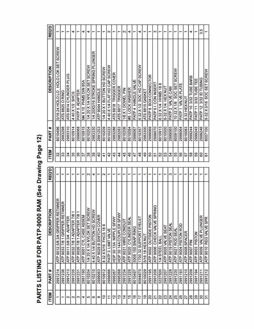
13
14 GRIPPER KITS & COMPONENTS FOR Airetool Models ATP & PATP Semi-Automatic Tube Pullers GRIPPER KITS AND COMPONENTS For Models ATP and PATP Tube Pullers TUBE SIZE * GRIPPER ** GRIPPER *** GRIPPER NOSE DRAW EXPANSION LOCK FRONT REAR O. D. GAGE SEGMENT COMLETE KIT BUSHING ROD NUT NUT "O" RING "O" RING 5/8 " " " " " " " " " 3/4 " " " " " " " " " " " " " /8 " " " " " " " " " " " " 1 " " " " " " " " " " " " " * Gripper segment only - 3 required for set. ** Gripper complete - Consists of 3 segments, 1 front "O" Ring and 1 back "O" Ring. *** Gripper Kit - Consists of 3 segments item # 1, and one each of items 2, 3, 4, 5, 6 and 7 shown above. Page - 14
15
16 Sales & Service Centers Note: All locations may not service all products. Please contact the nearest Sales & Service Center for the appropriate facility to handle your service requirements. Dallas, TX Detroit, MI Houston, TX Lexington, SC Apex Tool Group Apex Tool Group Apex Tool Group Apex Tool Group Sales & Service Center Sales & Service Center Sales & Service Center 670 Industrial Drive 1470 Post & Paddock 2630 Superior Court 6550 West Sam Houston Lexington, SC Grand Prairie, TX Auburn Hills, MI Parkway North, Suite 200 Tel: Tel: Tel: Houston, TX Tel: Fax: Fax: Tel: Fax: Fax: Los Angeles, CA Seattle, WA York, PA Canada Apex Tool Group Apex Tool Group Apex Tool Group Apex Tool Group Sales & Service Center Sales & Service Center Sales & Service Center Sales & Service Center Blackburn Avenue nd Avenue N.E East Market Street 5925 McLaughlin Road Norwalk, CA Redmond, WA York, PA Mississauga, Ont. L5R 1B8 Tel: Tel: Tel: Canada Fax: Fax: Fax: Tel: Fax: Germany England France China Cooper Power Tools Cooper Power Tools Cooper Power Tools SAS Cooper (China) Co., Ltd. GmbH & Co. OHG GmbH & Co. OHG a company of a company of a company of a company of Apex Tool Group, LLC Apex Tool Group, LLC Apex Tool Group, LLC Apex Tool Group, LLC 25 rue Maurice Chevalier 955 Sheng Li Road, Industriestraße 1 C/O Spline Gauges Ozoir-La-Ferrière Heqing Pudong, Shanghai Westhausen Piccadilly, Tamworth France China Germany Staffordshire B78 2ER Tel: Tel: Tel: +49 (0) United Kingdom Fax: Fax: Fax: +49 (0) Tel: Fax: Mexico Brazil Hungary Cooper Tools Cooper Tools Industrial Ltda. Cooper Tools Hungaria Kft. de México S.A. de C.V. a company of a company of a company of Apex Tool Group, LLC Apex Tool Group, LLC Apex Tool Group, LLC Av. Liberdade, 4055 Berkenyefa sor 7 Vialidad El Pueblito #103 Zona Industrial - Iporanga Pf: 640 Parque Industrial Querétaro Sorocaba 9027 Györ Querétaro, QRO SP Brazil Hungary Mexico Tel: Tel: Tel: +52 (442) Fax: Fax: Fax: +52 (442) Apex Tool Group, LLC 1000 Lufkin Road Apex, NC Phone: Fax: Airetool IM/Printed in USA 05/2011/Copyright Apex Tool Group, LLC
Airetool. 999-C-45 ( ) Electric Rolling Motor. Operating & Service Manual PL EN 01/26/2012
 Electric Rolling Motor. Operating & Service Manual PL EN 01/26/2012") Operating & Service Manual PL19-6009EN 999-C-45 (8405492) Electric Rolling Motor For additional product information visit our website at http://www.apextoolgroup.com PL19-6009EN Description Tool Specifications
Operating & Service Manual PL19-6009EN 999-C-45 (8405492) Electric Rolling Motor For additional product information visit our website at http://www.apextoolgroup.com PL19-6009EN Description Tool Specifications
Model PATP 9000 Ram ( ) Model PATP 9400 P Hydraulic Pump ( ) Model PATP HT Hose Tube Assembly ( )
 Model PATP 9400 P Hydraulic Pump ( ) Model PATP HT Hose Tube Assembly ( )") OPERATING & SERVICE MANUAL # 90113-IM REV 11/29/00 Airetool Model PATP 9000 Ram (5524902) Model PATP 9400 P Hydraulic Pump (2999307) Model PATP HT Hose Tube Assembly (5524903) READ SAFETY RECOMMENDATIONS
OPERATING & SERVICE MANUAL # 90113-IM REV 11/29/00 Airetool Model PATP 9000 Ram (5524902) Model PATP 9400 P Hydraulic Pump (2999307) Model PATP HT Hose Tube Assembly (5524903) READ SAFETY RECOMMENDATIONS
Parts Manual PL
 Parts Manual PL30-027-7 45-828 03/0/20 0L27 & 0K27 Series Low Profile Right Angle Grinder/Sander 2 Series Handles Shown Throttle Type Free Speed (RPM) Grinders / Sanders Termination 2,000 3,500 4,500 Type
35 Series Screwdrivers
 Parts Manal 823121EN 35 Series Screwdrivers For additional product information visit our website at http://www.apextoolgroup.com 823121EN Cleco Description Language Version: This Parts Manual is the Original
Airetool Airetrol Rolling Motor. Operating & Service Manual IM 03/23/2012
 Operating & Service Manual 90074-IM 1550-900 Airetrol Rolling Motor For additional product information visit our website at http://www.apextoolgroup.com 90074-IM Description Free Speed Maximum Torque Minimum
MA3W-2238 Radial Piston Power Motor
 Parts Manual MA3W-2238 Radial Piston Power Motor For additional product information visit our website at http://www.apextoolgroup.com Specifications and Description Specifications Table: Model Maximum
Balance Arms Air Cylinder and Spring Models
 Parts Manual 8385 0/06/0 Balance Arms Air Cylinder and Spring Models For additional product information visit our website at http://www.apextoolgroup.com Safety Recommendations For your safety and the
Airetool. 720 Series Airetrol Rolling Motor. Operating & Service Manual IM 05/11/2011
 Operating & Service Manual 90014-IM 05/11/2011 Airetool 720 Series Airetrol Rolling Motor Model Number Part Number (Order) 720-550-B 8405391 720-1800-B 8405383 720-2500-B 8405541 For additional product
Parts Manual PL C 12/28/2010. MP4400 Series (Type 4) Random Orbital Sander. Non-Vacuum Models. Vacuum Models MP 44 XX - XX XX
 Random Orbital Sander. Non-Vacuum Models. Vacuum Models MP 44 XX - XX XX") Parts Manual MP4400 Series (Type 4) Random Orbital Sander Non-Vacuum Models Vacuum Models MP 44 XX - XX XX Orbit Pattern 00 = 3/6" Offset (Black Handle) - Standard Sanding Orbit 03 = 3/32" Offset (Chrome
Parts Manual MP4400 Series (Type 4) Random Orbital Sander Non-Vacuum Models Vacuum Models MP 44 XX - XX XX Orbit Pattern 00 = 3/6" Offset (Black Handle) - Standard Sanding Orbit 03 = 3/32" Offset (Chrome
14TTA-2311 Pistol Grip Clecomatic Clutch Nutrunner
 Parts Manual 14TTA-2311 Pistol Grip Clecomatic Clutch Nutrunner For additional product information visit our website at http://www.apextoolgroup.com Model Nomenclature A 14 T T A - 2311 Tool Series 14
OPERATING INSTRUCTIONS AND SERVICE MANUAL
 OPERATING INSTRUCTIONS AND SERVICE MANUAL 5ML-.6B- 837 FIXTURIZED NUTRUNNER COMPLETE TOOL MODEL NO. CODE NO. 5ML-.6B-837 230837 READ SAFETY RECOMMENDATIONS BEFORE OPERATING TOOL Printed in U.S.A. 2--97
Parts Manual EN
 Parts Manual PL30-1211 12-11 Series Inline Extended Grinders For additional product information visit our website at http://www.apextoolgroup.com Nomenclature 12 X 1 1 XX - 36 XX OH Tool Series 12 = Ergo
SW100PRY220 ( ) Reversible Pistol Grip Swivel Reaction Bar Nutrunner
 Reversible Pistol Grip Swivel Reaction Bar Nutrunner") Parts Manual PL2-029EN Formerly: PC-468-5080 SW00PRY220 (4685080) Reversible Pistol Grip Swivel Reaction Bar Nutrunner Caterpillar # 8T-590 For additional product information visit our website at http://www.apextoolgroup.com
Parts Manual PL2-029EN Formerly: PC-468-5080 SW00PRY220 (4685080) Reversible Pistol Grip Swivel Reaction Bar Nutrunner Caterpillar # 8T-590 For additional product information visit our website at http://www.apextoolgroup.com
48EP Series Electronically Controlled Pistol Grip Nutrunner
 Parts Manual PL2EN-48EP- 0/09/202 48EP Series Electronically Controlled Pistol Grip Nutrunner For additional product information visit our website at http://www.apextoolgroup.com PL2EN-48EP- 0/09/202 Cleco
48EP Series Electronically Controlled Pistol Grip Nutrunner
 Parts Manual PL2EN-8EP /0/20 8EP Series Electronically Controlled Pistol Grip Nutrunner For additional product information visit our website at http://www.apextoolgroup.com PL2EN-8EP /0/20 Cleco General
19RA Series Right Angle Nutrunner
 Parts Manual P12-1014EN 19RA Series Right Angle Nutrunner For additional product information visit our website at http://www.apextoolgroup.com P12-1014EN Cleco Model Nomenclature A 19 R A X XX XX X Tool
Product Manual PL31-15LF 04/02/ LF Series Inline Grinders
 Product Manual PL31-15LF 15LF Series Inline Grinders 15 L F 0 X X - XX NL Tool Series 15 = Drill Throttle Type L = Locking Lever Motor Size F = 0.4 hp Handle Style 0 = Straight Exhaust Type 5 = Front Exhaust
Airetool. CC-325-HP High Pressure Water Flush Condenser Tube Cleaner. Operating & Service Manual IM 05/11/2011
 Operating & Service Manual 90093-IM 05/11/2011 Airetool CC-325-HP High Pressure Water Flush Condenser Tube Cleaner For additional product information visit our website at http://www.apextoolgroup.com Safety
10R90 Series Light Duty Precision Turbine Grinder
 Parts Manual 45-8043 10R90 Series Light Duty Precision Turbine Grinder CAUTION Do Not Lubricate This Tool! For additional product information visit our website at http://www.apextoolgroup.com 45-8043 Dotco
A6R-2218 Reversible Axial Piston Power Motors
 Instruction Manual A6R-2218 Reversible Axial Piston Power Motors For additional product information visit our website at http://www.apextoolgroup.com Nomenclature Model Number Maximum Allowable RPM * Stall
15D Series Pistol Grip and Inline Drills
 Parts Manual 823144EN 15D Series Pistol Grip and Inline Drills For additional product information visit our website at http://www.apextoolgroup.com 823144EN Cleco Product Information The original language
21L1341 Series Inline Vent Trimmer
 Parts Manual 21L1341 Series Inline Vent Trimmer For additional product information visit our website at http://www.apextoolgroup.com Nomenclature Includes (Illustration "B") Model Vent Trimmer Drive Pinion
75RM-2024 Right Angle Fixtured Nutrunner
 Instruction Manual PL12-1092EN 75RM-2024 Right Angle Fixtured Nutrunner For additional product information visit our website at http://www.apextoolgroup.com Cleco Product Information PL70-1092EN The original
135DPV-B Series Variable Speed Drills
 Operation & Service Manual 82040 2/0 5DPV-B Series Variable Speed Drills Drill: Series: 5 5 D PV - XX B - XX Drill Chuck: 42 (/8-24B) /4 HD Capacity 4 (/8-24B) /8 HD Capacity 50 (/8-24B) /2 Capacity 5
12-10 Series Inline Grinder
 Parts Manual 45-858EN 2-0 Series Inline Grinder Termination -36 Terminations -4 and -6 For additional product information visit our website at http://www.apextoolgroup.com 45-858EN Dotco Nomenclature and
400QGDBV Series S400 & S600 In-line Positive Feed Drills
 Parts Manual 8 06/0/0 400QGDBV Series S400 & S600 Inline Positive Feed Drills For additional product information visit our website at http://www.apextoolgroup.com Safety Recommendations For your safety
88 Series Screwdrivers
 Parts Manual 8308 0/07/0 88 Series Screwdrivers For additional product information visit our website at http://www.apextoolgroup.com Safety Recommendations For your safety and the safety of others, read
Technical Information Cutting Speeds
 Technical Information Cutting Speeds Speed, Feed & Power Please use the chart below as a guide only. Many variables contribute to the optimum parameters for each application. These variables include: particular
Parts Manual EN PL /18/ L41 Series Inline Extended Grinders
 Parts Manual 45-8188EN PL30-850 12L41 Series Inline Extended Grinders For additional product information visit our website at http://www.apextoolgroup.com 45-8188EN Dotco Nomenclature 12 L 4 1 XX - XX
P-15 & MP-15 SERIES POWER TOOL ANALYZER
 Operation & Service Manual 8373 /0 P-5 & MP-5 SERIES POWER TOOL ANALYZER XX-5 Series: P-5 Inch Pounds Newton-Meters (4-60) (.5-8) Order Number: 8000 MP-5 Centimeter-Kilograms (5-80) 805 Newton-Meters (.5-8)
SERVICE&OPERATING MANUAL INSTRUCTION
 QUALITY TUBE TOOLS KRAIS Tube Expanders SERVICE&OPERATING MANUAL INSTRUCTION For models: K72-RT-90, K72-RT-90-280, K73-RT-190, K73-RT-190-375, K72-LT-90, K72-LT-90-280, K73-LT-190, K73-LT-190-375 READ
21 Series Double Reduction Rotary Vane Power Motors
 Instruction Manual 45-8059EN Series Double Reduction Rotary Vane Power Motors For additional product information visit our website at http://www.apextoolgroup.com 45-8059EN Cleco General Information For
14PTA & 14TTA Series Pistol Grip Nutrunners
 Parts Manual 4PTA & 4TTA Series Pistol Grip Nutrunners 4PTA Series 4TTA Series For additional product information visit our website at http://www.apextoolgroup.com Product Information The original language
Torque Controlled Tube Rolling Motor
 TM-82 9-02-05 Torque Controlled Tube Rolling Motor 9040-1800 Operating and Maintenance Instructions Elliott Tool Technologies Ltd 1760 Tuttle Avenue Dayton, Ohio 45403 U.S.A. Phone: +1 800 332 0447 +1
14RA Series Right Angle Nutrunners
 Parts Manual 822EN RA Series Right Angle Nutrunners For additional product information visit our website at http://www.apextoolgroup.com 822EN Cleco General Information anguage Version: This Parts Manual
SERVICE&OPERATING MANUAL INSTRUCTION
 QUALITY TUBE TOOLS SERVICE&OPERATING MANUAL INSTRUCTION For models: K20-550, K20-1800, K20-2500 READ SAFETY RECOMMENDATIONS BEFORE OPERATING THIS TOOL Poland, 55-106 Zawonia, Czachowo 15 tel. +48 71 312
Airetool. Gas Line Cleaners Range: 3/4 (19.05mm) to 1-1/2 (38.10mm) Operating & Service Manual PL EN 10/01/2015
 to 1-1/2 (38.10mm) Operating & Service Manual PL EN 10/01/2015") Operating & Service Manual PL9-6026EN 0/0/205 Airetool Gas Line Cleaners Range: 3/4 (9.05mm) to -/2 (38.0mm) For additional product information visit our website at http://www.apextoolgroup.com PL9-6026EN
Operating & Service Manual PL9-6026EN 0/0/205 Airetool Gas Line Cleaners Range: 3/4 (9.05mm) to -/2 (38.0mm) For additional product information visit our website at http://www.apextoolgroup.com PL9-6026EN
1700 and 1900 Series Horizontal Grinders
 Instruction Manual 823136EN 1700 and 1900 Series Horizontal Grinders For additional product information visit our website at http://www.apextoolgroup.com 823136EN Cleco General Information For this Instruction
Parts Manual PL EN 05/19/ L4321 Router. For additional product information visit our website at
 Parts Manual 10L4321 Router For additional product information visit our website at http://www.apextoolgroup.com Product Information The original language of this manual is English. Product Safety Information:
Parts Manual EN PL30-12R04 07/21/ R04 Series 0.1 HP Inline Pencil Grinder
 Parts Manual PL30-12R04 12R04 Series 0.1 HP Inline Pencil Grinder For additional product information visit our website at http://www.apextoolgroup.com Dotco Nomenclature 12 R 04 XX - X X Series 12 = Ergo
445 Series Motors. Operating and Maintenance Instructions. Models 445L , 445R , 445L , 445R
 445 Series Motors Models 445L1753-190, 445R1753-190, 445L1752-90, 445R1752-90 Tube & Pipe Cleaners Tube Testers Tube Plugs Tube Removal Tube Installation Operating and Maintenance Instructions www.elliott-tool.com
15K Series Extented Mini Right Angle Drill Attachment
 Parts Manual PL30-2052EN 15K27-5172 Series Extented Mini Right Angle Drill Attachment For additional product information visit our website at http://www.apextoolgroup.com PL30-2052EN Dotco Nomenclature
10LF and 12LF Series Right Angle Grinders
 Product Manual 10LF and 12LF Series Right Angle Grinders XX L F 2 XX - XX Tool Series 10 = Aluminum Housing 12 = Ergo Housing Throttle Type L = Locking Lever Motor Size F = 0.4 hp Handle Style 2 = Right
10N10 Series Inline Grinder
 Parts Manual 0N0 Series Inline Grinder For additional product information visit our website at http://www.apextoolgroup.com Nomenclature and Specifications Product Type 0 = Aluminum Housing Grinder Throttle
A6R-2221 Reversible Axial Piston Power Motor
 Instruction Manual A6R-2221 Reversible Axial Piston Power Motor For additional product information visit our website at http://www.apextoolgroup.com Nomenclature Model Number Maximum Allowable RPM Stall
10N M6 Series Right Angle Grinder
 Parts Manual PL30-2042EN 10N1200-36M6 Series Right Angle Grinder For additional product information visit our website at http://www.apextoolgroup.com PL30-2042EN Dotco Nomenclature and Specifications Product
Airetool AIRETOOL MODEL 720 PISTOL GRIP AIRETROL. Model B ( ) Model B ( ) Model B ( )
 Model B ( ) Model B ( )") OPERATING & SERVICE MANUAL # 90014-IM REV 07/25/01 Airetool AIRETOOL MODEL 720 PISTOL GRIP AIRETROL Model 720-550-B (8405391) Model 720-1800-B (8405383) Model 720-2500-B (8405541) READ SAFETY RECOMMENDATIONS
OPERATING & SERVICE MANUAL # 90014-IM REV 07/25/01 Airetool AIRETOOL MODEL 720 PISTOL GRIP AIRETROL Model 720-550-B (8405391) Model 720-1800-B (8405383) Model 720-2500-B (8405541) READ SAFETY RECOMMENDATIONS
41NDR Series Air Shut-Off Ratchet Wrench
 Instruction Manual PL17EN-41NDR 41NDR Series Air Shut-Off Ratchet Wrench For additional product information visit our website at http://www.apextoolgroup.com PL17EN-41NDR Cleco General Information For
N60 Rotary Vane Pneumatic Motor
 Parts Manual PL70-1043EN 24-1312N60 Rotary Vane Pneumatic Motor For additional product information visit our website at http://www.apextoolgroup.com PL70-1043EN Cleco 24-1312N60 Rotary Vane Motor Model
10LF and 12LF Series Right Angle Grinder and Sander
 Product Manual 4-842EN 10LF and LF Series Right Angle Grinder and Sander For additional product information visit our website at http://www.apextoolgroup.com 4-842EN Dotco Nomenclature XX L F 2 XX - XX
Parts Manual EN
 Parts Manual 45-8213EN PL30-1212 12L12 and 12S12 Series 0.3 HP Right Angle Grinder/Sander For additional product information visit our website at http://www.apextoolgroup.com 45-8213EN Dotco Nomenclature
Peck Feed Drills ADVANCED DRILLING EQUIPMENT 3-1 SP EN M
 Peck Feed Drills ADVANCED DRILLING EQUIPMENT SP-1300-3-EN-0806-.25M 3-1 Introduction Peck Feed Drills Our peck feed drills are a unique category unto themselves. These drills drill a short distance, then
MR30 Series Rotary Vane Power Motors
 Instruction Manual PL70-1057EN MR30 Series Rotary Vane Power Motors For additional product information visit our website at http://www.apextoolgroup.com PL70-1057EN Cleco General Information For this Instruction
DC Electric Assembly Tools
 APTOOL.RU Phone: +7 (495) 723-19-55 Please note that all locations may not service all products. Please contact the nearest Apex Tool Group Sales & Service Center for the appropriate facility to handle
Maintenance Information
 51984144 Edition 6 May 2014 Air Paving Breaker MX60 & MX90 Maintenance Information Save These Instructions Product Safety Information WARNING Failure to observe the following warnings, and to avoid these
88 Series Inline and Pistol Grip Screwdrivers
 Parts Manual 823018EN 88 Series Inline and Pistol Grip Screwdrivers For additional product information visit our website at http://www.apextoolgroup.com 823018EN Cleco Nomenclature 88 XXX A XX - X C X
Operating Manual & Safety Instructions ProTorc Hydraulic Torque Wrench Model # PTLC - Please read in full before operating ProTorc Torque Wrench -
 Operating Manual & Safety Instructions ProTorc Hydraulic Torque Wrench Model # PTLC - Please read in full before operating ProTorc Torque Wrench - ProTorc Important Safety Instructions READ ALL INSTRUCTIONS
INSTRUCTIONS AND PARTS LIST FOR MODEL 125H & 150H HAND-OPERATED HYDRAULIC PRESS
 INSTRUCTIONS AND PARTS LIST FOR MODEL 125H & 150H HAND-OPERATED HYDRAULIC PRESS SETTING UP THE PRESS FOR OPERATION For shipping convenience, the gauge, pump handle, hoist crank, screw nose and base angles
INSTRUCTIONS AND PARTS LIST FOR MODEL 25H HAND-OPERATED HYDRAULIC PRESS
 INSTRUCTIONS AND PARTS LIST FOR MODEL 25H HAND-OPERATED HYDRAULIC PRESS SETTING UP THE PRESS FOR OPERATION For shipping convenience, the gauge, pump handle, hoist crank, screw nose and base angles were
Tube Removal Tools. Tube Pulling Systems & Pumps. Tube Pulling Pumps & Accessories
 Tube Removal Tools Tube Pulling Systems & Pumps Tube Pulling Systems consist of: 1. Pump Assembly - air/hydraulic or electric/hydraulic (includes hose assembly) 2. Ram Assembly - gripper or spear type
PRIME 4 Service. Smith Meter Rotary Vane Meters. Contents
 Smith Meter Rotary Vane Meters PRIME 4 Service Issue/Rev. 0.4 (7/11) Bulletin MN01041 Contents Trouble Shooting... Page 2 Genuine Smith Meter Parts... Page 2 Special Tools and Fixtures... Page 2 Disassembly
HYDRAULIC TUBE CUTTER
 7, OD 7, -/ OD 7, OD HYDRAULIC TUBE CUTTER OPERATING INSTRUCTIONS & SERVICE MANUAL Rev: A, //007 TO REDUCE THE RISK OF INJURY AND EQUIPMENT DAMAGE USER MUST READ AND UNDERSTAND OPERATOR S MANUAL. Thomas
SP-1037EN M. Durable Production Performance. CurrentControl For Quality Critical Joints
 SP-1037EN 0208 7.5M Durable Production Performance CurrentControl For Quality Critical Joints Cleco CurrentControl 18 & 48 Series Durability. Spee Cost Effective Solution for Quality Critical Applications.
INSTALLATION, OPERATION AND MAINTENANCE MANUAL (IOM)
") INSTALLATION, OPERATION AND MAINTENANCE MANUAL (IOM) IOM-1088 03-16 Model 1088 Vacu-Gard Blanketing Valve ISO Registered Company SECTION I I. DESCRIPTION AND SCOPE The Model 1088 Vacu-Gard is a tank blanketing
INSTALLATION, OPERATION AND MAINTENANCE MANUAL (IOM) IOM-1088 03-16 Model 1088 Vacu-Gard Blanketing Valve ISO Registered Company SECTION I I. DESCRIPTION AND SCOPE The Model 1088 Vacu-Gard is a tank blanketing
IBT Series Square Drive Torque Wrenches
 IBT Series Square Drive Torque Wrenches Operation and Maintenance Manual Model.75, 1, 3, 5, 8, 10, 20, 25, 35, 50 http://www.torsionx.com Use the IBT Series Square Drive Torque Wrenches Model.75, 1, 3,
 Operation and Maintenance Manual http://www.torsionx.eu Use the MaxDrv Series Square Drive Torque Wrench Model.75, 1, 3, 5, 8, 10, 20, 25, 35, 50 to install and remove threaded fasteners requiring precise
SERIES OPERATION AND MAINTENANCE MANUAL
 SERIES OPERATION AND MAINTENANCE MANUAL This manual CONTAINS IMPORTANT WARNINGS, S and OTHER INSTRUCTIONS. Read and understand the instruction manual Carefully, before use and retain it for reference.
FSG175 FENCE STAPLE GUN
 Kencove Farm Fence Supplies 344 Kendall Rd Blairsville, PA 15717 1-800-KENCOVE sales@kencove.com www.kencove.com OPERATING MANUAL FSG175 FENCE STAPLE GUN To reduce the risk of possible injury, read the
Operating instructions Form no safety definitions
 Operating instructions Form no. 1000437 safety definitions safety symbols are used to identify any action or lack of action that can cause personal injury. Your reading and understanding of these safety
OPERATION AND MAINTENANCE MANUAL
 WREN IBT SERIES HYDRAULIC TORQUE WRENCHES IBT SQUARE DRIVE SERIES OPERATION AND MAINTENANCE MANUAL FOR WREN Products: POINT 75, 1IBT, 3IBT, 5IBT, 8IBT, 10IBT, 20IBT, 25IBT, 35IBT, 50IBT SQUARE DRIVE HYDRAULIC
Backpack Sprayer. Use and Care Manual
 Backpack Sprayer Use and Care Manual BACKPACK SPRAYER CAUTION: Read and follow all instructions Do Not Return This Backpack To The Store For Help, Information or Parts, Call : 1-800-311-9903 The Fountainhead
Air / Hydraulic Pump Instructions. CAUTION: Read and Understand These Operating, Servicing, and Safety Instructions, Before Using This Machine.
 Air / Hydraulic Pump Instructions CAUTION: Read and Understand These Operating, Servicing, and Safety Instructions, Before Using This Machine. 1-800-467-2464 10 Cooperative Way Wright City, MO 63390 P.O.
Model No. 9011C Midi-Torq Pneumatic Rolling Control
 Model No. 9011C Midi-Torq Pneumatic Rolling Control For 3/8-3/4 (9.53-19.05mm) Tube OD Tube & Pipe Cleaners Tube Testers Tube Plugs Tube Removal Tube Installation Operating and Maintenance Instructions
FTMP-8 AND FTMP-12 Midget Puller Units
 401 Andover Park East Seattle, Washington 98188-7605 USA (206) 246-2010 FTI OPERATIONS, MAINTENANCE AND REPAIR MANUAL FTMP-8 AND FTMP-12 Midget Puller Units FTI Part #2720-021 Revision A November 18, 2011
Air / Hydraulic Pump
 Form No. 538016 Parts List & Operating Instructions for: 2510A Original Instructions Air / Hydraulic Pump Maximum Capacity: 690 bar (10,000 psi) Description: The 2510A air/hydraulic pump is designed to
Parts Manual EN
 Parts Manual 4-83EN PL30- - Series Right Angle Grinder, Sander, and Router For additional product information visit our website at http://www.apextoolgroup.com 4-83EN Dotco Nomenclature X XX - XX XX XX
Temperature Sensor Series
 GENERAL DESCRIPTION The patented* No. 85026-Series Temperature Sensor contains a two-position valve operated by temperature variations around the integral sensing bulb. It is used to vent or block a pneumatic
Installation Manual For ISL98, ISL03, ISL07, ISC07
 Installation Manual For ISL98, ISL03, ISL07, ISC07 Table of Contents Section 1: Introduction... 3 Housing Identification... 3 Engine Identification... 3 Special Tools... 3 Automatic Transmissions... 3
Maintenance Instructions
 General Note These instructions contain information common to more than one model of Bevel Gear Drive. To simplify reading, similar models have been grouped as follows: GROUP 1 Models 11, 0, 1,, (illustrated),,
9017 Super Maxi-Torq Pneumatic Rolling Control
 9017 Super Maxi-Torq Pneumatic Rolling Control (For serial numbers starting with 9017-100) For 3/4 1-1/2 (19.1mm 38.1mm) Tube O.D. Tube & Pipe Cleaners Tube Testers Tube Plugs Tube Removal Tube Installation
Hard Seat Fluid Pressure Regulator
 Instruction Sheet P/N 04742-02 Description The Nordson hard seat fluid pressure regulator is designed for use with abrasive coatings. The regulator body is constructed of stainless steel with a nickel-plated
Airless Spray Gun INSTRUCTIONS DP psi (345 bar) Maximum Working Pressure
 Maximum Working Pressure") INSTRUCTIONS DP-6376 Airless Spray Gun 5000 psi (345 bar) Maximum Working Pressure INSTRUCTIONS This manual contains important warnings and information. READ AND KEEP FOR REFERENCE. Table of Contents Warnings......................................
INSTRUCTIONS DP-6376 Airless Spray Gun 5000 psi (345 bar) Maximum Working Pressure INSTRUCTIONS This manual contains important warnings and information. READ AND KEEP FOR REFERENCE. Table of Contents Warnings......................................
Air-Assist Service Jack Max. Capacity: 10 Tons
 Form No. 565786 Parts List & Operating Instructions for: 1511B Air-Assist Service Jack Max. Capacity: 10 Tons 109 67 66 68 77 69 70 78 95 94 107 106 108 26 71 72 72 93 X L 65 75 92 91 90 89 88 87 86 85
MM Series Radial Piston Power Motors
 Instruction Manual MM Series Radial Piston Power Motors For additional product information visit our website at http://www.apextoolgroup.com Specifications Model Number Maximum Allowable Stall Starting
Model DFR 070/156/220 Rotary Actuator
 Figure 1 DFR 156 TABLE OF CONTENTS General 2 Actuator Assembly 18 Scope 2 Bushing / Yoke Assembly 18 Principles of Operation 2 Spring Barrel Assembly 18 Safety Caution 2 Diaphragm Plate Assembly 20 Specifications
Low Profile Wrenches Operation and Maintenance Manual
 Low Profile Wrenches Operation and Maintenance Manual http://www.torquetoolsinc.com Use the HEXPRO Series Low Profile Wrenches Model 2HP 4HP 8HP 14HP 30HP to install and remove large bolts that have minimal
OPERATOR S MANUAL Model 60010
 OPERATOR S MANUAL Model 60010 10- TON SNAP LOCK PORTA POWER SET W/ WHEELED CASE PROFESSIONAL HYDRAULIC JACKS 1531 W. Mohawk Drive Phone 715-453-9602 Customer Service 800-995-2250 Tomahawk, WI 54487 Fax
OPERATION AND PARTS MANUAL
 OPERATION AND PARTS MANUAL MODEL NUMBER : PART NUMBER : GTL 1110 1900-0510 SERIAL NUMBER : BAYNE MACHINE WORKS, INC. PHONE: (864) 288-3877 910 FORK SHOALS ROAD TOLL FREE: (800) 535-2671 GREENVILLE S.C.,
HexPro Series Low Profile Wrenches
 HexPro Series Low Profile Wrenches Operation and Maintenance Manual Model 2HP 4HP 8HP 14HP 30HP www.torquetoolsinc.com Use the HEXPRO Series Low Profile Wrenches Model 2HP 4HP 8HP 14HP 30HP to install
RUFNEX Series Low Profile Wrenches Operation and Maintenance Manual
 RUFNEX Series Low Profile Wrenches Operation and Maintenance Manual http://www.torsionx.com Use the RUFNEX Series Ultra-Low Profile Wrenches to install and remove large bolts that have minimal wrench clearance.
 Operation and Maintenance Manual Model.75,, 3, 5, 8, 0, 0, 5, 35, 50 http://www.torsionx.com Use the MaxDrv Series Square Drive Torque Wrench Model.75,, 3, 5, 8, 0, 0, 5, 35, 50 to install and remove threaded
Flexfence Tension Unit. with Hand Pump. Product Manual. Release 02/16.
 Flexfence Tension Unit with Hand Pump Product Manual www.ingalcivil.com.au 1.0 Safety Precautions 1.1 Personal Protection While operating this equipment it is recommended that the following personal protective
HYDRAULICS. TX420 & & lower. Hydraulic Tandem Pump Removal. 4. Remove the LH side panel (Fig. 0388).
.") TX420 & 425 240000299 & lower 4. Remove the LH side panel (Fig. 0388). Hydraulic Tandem Pump Removal Note: Cleanliness is a key factor in a successful repair of any hydraulic system. Thoroughly clean all
TX420 & 425 240000299 & lower 4. Remove the LH side panel (Fig. 0388). Hydraulic Tandem Pump Removal Note: Cleanliness is a key factor in a successful repair of any hydraulic system. Thoroughly clean all
Valtek Spring Cylinder Linear Actuators
 Valtek Linear Actuators GENERAL INFORMATION The following instructions are designed to assist in installing, troubleshooting and servicing Valtek spring cylinder actuators. Product users and maintenance
Valtek Auxiliary Handwheels and Limit Stops
 Valtek Auxiliary s and Limit Stops Table of Contents Page 1 General information 2 Installation 2 Side-mounted handwheels, size 25 and 50 (linear actuators) 3 Side-mounted handwheels, size 100 and 200 (linear
Operating, Servicing, and Safety Manual Model # Hydraulic Bender
 Operating, Servicing, and Safety Manual Model # 900 90 Hydraulic Bender CAUTION: Read and Understand These Operating, Servicing, and Safety Instructions, Before Using This Machine. 1-800-467-2464 10 Cooperative
AIR/HYDRAULIC INJECTION GUN MODEL INSTRUCTIONS
 I. OPERATION & DESCRIPTION The Air / Hydraulic Injection Gun is a high-pressure tool that should be used with caution and according to these instructions. IMPORTANT: The Gun is 0,000 psi rated. Do not
MODELS 44 ARA 44 ARAC 44 RA4 44 RA2
 General Safety and Maintenance Manual Model 44ARA Angle Grinder with 4 guard. Model 44ARAC Angle Grinder with built in 1/4 collet for use with carbide burrs. Model 44ARAZ Angle Grinder with spiral cool
Hydraulic Gear Puller Instruction Manual
 + HGP053-M0_052015 Hydraulic Gear Puller Instruction Manual MODELS: HGP053 HGP103 HGP153 HGP253 HGP503-5 Ton Capacity -10 Ton Capacity -15 Ton Capacity -25 Ton Capacity -50 Ton Capacity SFA Companies 10939
MANUAL. TU Series. TU Series. Square Drive Hydraulic Torque Wrenches MODELS TU-2, TU-3, TU-5, TU-7, TU-11, TU-20, TU-27 & TU-60
 TU Series OPERATION AND MAINTENANCE MANUAL TU Series Square Drive Hydraulic Torque Wrenches MODELS TU-2, TU-3, TU-5, TU-7, TU-11, TU-20, TU-27 & TU-60 1025 Conroy Place, Easton, PA. 18040 U.S.A. Phone: