Renault ALASKAN. Vehicle user manual
|
|
|
- David Flynn
- 5 years ago
- Views:
Transcription

1 Renault ALASKAN Vehicle user manual


2 A passion for performance ELF, partner of RENAULT recommends ELF Partners in cutting-edge automotive technology, Elf and Renault combine their expertise on both the racetrack and the city streets. This enduring partnership gives drivers a range of lubricants perfectly suited to Renault cars. Lasting protection and optimum performance for your engine guaranteed. Whether changing the oil or simply topping up, to find the approved ELF lubricant best suited to your vehicle, ask your Renault dealer for a recommendation or consult your vehicle maintenance handbook. A brand from
3 Foreword This handbook was prepared to help youunderstand the operation and maintenanceofyour vehicle so that youmay enjoy manykilometres (miles) of driving pleasure. Please read through this handbook before operating your vehicle. Aseparate Warranty Information &Maintenance Booklet explains in detail the warranty coverage that applies to your vehicle. Your approved dealer knowsyour vehicle best. When yourequireany serviceorhave anyquestions, your approved dealer will be glad to assist youwith theextensive resources available for you. IMPORTANT SAFETY INFORMATION REMINDERS! Follow these important driving rules to help ensureasafeand complete trip for you and your passengers! NEVER drive under the influenceofalcoholordrugs. ALWAYS observe posted speed limits and never drive too fast for conditions. ALWAYS give your full attention to driving and avoid using vehicle features or taking other actions that could distractyou. ALWAYS use your seat belts and appropriate child restraint systems. Preteen children should be seatedinthe rear seat. ALWAYS provide information about the proper use of vehicle safety features to all occupants of the vehicle. ALWAYS review this Driver's handbook forimportant safety information. WHEN READING THE HANDBOOK This handbook includes information for all options available on this model. Therefore, you may find some information that does not apply to your vehicle. Throughout this handbook, some illustrations may only show the layout for Left-Hand Drive (LHD) models. For Right-Hand Drive (RHD) models, the illustrated shape and location of some components may differ. All information, specifications and illustrations in this handbook are those in effect at the time of printing. RENAULT reserves the right to change specifications or designs at any time without notice and without obligation. MODIFICATION OF YOUR VEHICLE This vehicle cannot be modified without taking into consideration the RENAULT Bodybuilders Standards for Assembly, Equipment and Conversion that has been written for this purpose. All modifications done which do not follow the instructions in that document could affect the vehicle functioning and its lifetime. Furthermore, failure to comply with these Standards may arise in security problems and could even result in prosecution. Damages or failures in the vehicle as a consequence of modifications may not be covered under RENAULT warranty. READ FIRST THEN DRIVE SAFELY Before driving your vehicle, read this Driver's handbook carefully. This will ensure familiarity with controls and maintenance requirements, assisting you in the safe operation of your vehicle. Throughout this handbook the following symbols and words are used: WARNING Indicates the presence of a hazard that could cause death or serious personal injury. To avoid or reduce the risk, the procedures described must be followedprecisely. CAUTION Indicates the presence of a hazard that could cause minor or moderate personal injury, or damage to your vehicle. To avoid or reduce the risk, the procedures described must be followed carefully. NOTE Indicatesadditionalhelpful information.
4 Air bag warning labels: This symbol means Do not do this or Do not let this happen. Arrowsinanillustration that aresimilar to these point to the front of the vehicle. Arrows inanillustration that are similar to these indicate movement or action. Arrowsinanillustration that aresimilar to these call attention to an item in the illustration. [ ]: Square brackets are used to indicate messages, keys, or items displayed on a screen. < >: Chevrons or angle brackets are used to indicate texts on controls like buttons or switches inside or on the vehicle. NEVER use a rearward facing child restraint on a seat protected by an ACTIVE AIRBAG in front of it, DEATH or SERIOUS INJURYtothe CHILD can occur. Be sure toread the Air bag warning labels description inthe Safety section of this handbook; and the Air bag label description atthe end of this handbook. ON-PAVEMENT AND OFF-ROAD DRIVING (4WD models) This vehicle will handle and manoeuvre differently from an ordinary passenger vehicle, because it has a higher centre of gravity.as with other vehicles with features of this type, failure to operate this vehicle correctly may result in loss of control or an accident. Be sure to read On-pavement and off-road driving precautions and Fourwheel drive (4WD) in the 5.Starting and driving section ofthis handbook. BATTERYDISPOSAL CAUTION An improperly disposed battery can harm the environment. Always confirm local regulations forbattery disposal.
5 Examples ofthe batteries that the vehicle contains: Vehicle battery Remote controller battery (for Remote Control Key and/or Remote keyless entry system) Tyre Pressure Monitoring System (TPMS) sensor battery Remote controller battery (for Mobile Entertainment system) If in doubt,contact your local authority,orapproved dealer,oraqualified workshop for advice ondisposal. m Bluetooth is atrademark owned by Bluetooth SIG,Inc. and licensed to Visteon Corporation. ipod is atrademark of Apple Inc. m Gracenote and CDDB are registered trademarks of Gracenote,Inc. The Gracenote logo and logo type,and m the Powered by Gracenote logo are trademarks of Gracenote.
6
7 Contents Illustrated tableofcontents 0 Safety seats, seat belts and supplemental restraint system Instruments and controls 2 Pre-driving checksand adjustments 3 Display screen, heater and air conditioner,and audio system Starting and driving 5 In case of emergency 6 Appearanceand care 7 Maintenanceand do-it-yourself 8 Technical information 9 Index
8
9 0 Illustratedtabletable of contents Seats, seat belts and Supplemental Restraint System (SRS) Exterior front Exterior rear Passenger compartment Cockpit Left-Hand Drive (LHD) model Right-Hand Drive (RHD) model Instrument panel Left-Hand Drive (LHD) model Right-Hand Drive (RHD) model Meters and gauges Engine compartment M9T2.3DCI engine
10 SEATS, SEATBELTS AND SUPPLEMENTAL RESTRAINTSYSTEM (SRS) *: where fitted NIC Supplemental front-impact air bags* (P.1-29) 2. Front passenger air bag switch* (P.1-37) 3. Supplemental curtain side-impact air bags* (P.1-30) 4. Seat belts (P.1-9) 5. Head restraints (P.1-6) 6. Child restraint anchor point* (for top tether strap child restraint) (P.1-21) 7. Rear seats* (P.1-5) or Jump seat* (P.1-6) 8. Supplemental side-impact air bags* (P.1-29) 9. Pre-tensioner seat belt system* (P.1-33) 10. Front seats (P.1-2) 11. Supplemental driver's knee air bag* (P.1-29) 0-2 Illustrated table of contents
11 EXTERIOR FRONT 9. Side turn signal lights Bulb replacement (P.8-24) 10. Tyres Tyres and wheels (P.8-27) Flat tyre (P. 6-2) Specifications (P. 9-4) Four-Wheel Drive (4WD)*1 (P.5-25) 11. Headlights and turn signal lights Switch operation (P.2-26) Bulb replacement (P.8-21) 12. Headlight cleaner*1 Operation (P.2-30) 13. Front fog lights*1 or Daytime running lights*1 Switch operation (P.2-28, P. 2-27) Bulb replacement (P.8-24) 14. Towing eye*2 (P.6-14) *1: where fitted *2: The layout illustrated is for the Right-Hand Drive (RHD) model.onthe Left-Hand Drive (LHD) model, the towing eye islocated on the opposite side. NIC Bonnet (P.3-17) 2. Windscreen wipers and washers Switch operation (P.2-29) Wiper blade replacement (P.8-16) Window washer fluid (P.8-11) 3. Sunroof*1 (P.2-37) 4. Windows (P. 2-31) 5. Roof rail*1 (P.2-35) 6. Child safety rear door locks*1 (P.3-5) 7. Doors Keys (P.3-2) Door locks (P. 3-4) Remote keyless entry system*1 (P.3-6) Remote Control Key system*1 (P.3-7) Security system*1 (P.3-15) 8. Outside rearview mirrors (P. 3-25) Illustrated table of contents 0-3
12 EXTERIOR REAR NIC Rear window defogger* (P.2-29) 2. High-mounted stop light* (P.5-42) 3. Antenna* (P. 4-32) 4. AdBlue filler lid (P.3-19) 5. Rear view camera* Reversing camera* (P.4-7) 6. Cargo bed* (P. 3-20) 7. Rear combination lights (bulb replacement) (P.8-24) 8. Number plate lights (bulb replacement) (P.8-24) 9. Parking sensor (sonar)* (P.5-39) *: where fitted 0-4 Illustrated table of contents
13 PASSENGER COMPARTMENT 11. Door armrest Power window controls* (P.2-31) Power door lock switch (driver's door)* (P.3-4) Outside rearview mirror remote control switch (driver's door)* (P.3-25) *: where fitted NIC Inside rearview mirror (P.3-23) 2. Sunglasses holder (P.2-34) 3. Microphone* Bluetooth Hands-Free Phone System* (P.4-55,P.4-61) 4. Sunroof switch* (P.2-37) 5. Map lights (P.2-38) 6. Sun visors (P. 2-36) 7. Room light* (P.2-39) 8. Rear personal light* (P.2-39) 9. Console box* (P.2-35) Power outlet (P.2-33) 10. Cup holders* (P.2-35) Illustrated table of contents 0-5
14 COCKPIT NIC3089 Vehicle information display control switch* (P.2-13) 7. Wiper and washer switch (P.2-29) 8. Steering-wheel-mounted controls* (right side) Cruise control system* (P. 5-33) Speed limiter system* (P.5-35) Hands-Free Phone System switch* (P.4-55, P. 4-62) 9. Shift lever Automatic Transmission (AT) (P.5-13) Manual Transmission (MT) (P.5-16) 10. Tilting steering wheel lever* (P.3-23) 11. Fuel filler lid opener switch (P.3-18) 12. Parking sensor (sonar) system off switch* (P.5-39) Active Emergency Braking system off switch* (P.5-29) Electronic Stability Programme (ESP) OFF switch (P. 5-27) Headlight cleaner switch* (P.2-30) Stop/Start OFF switch* (P.5-17) Headlight aiming control* (P.2-27) *: where fitted LEFT-HAND DRIVE (LHD) MODEL 1. Instrument brightness control switch (P. 2-4) 2. <TRIP RESET> switch for twin trip odometer (P.2-17) 3. Instrument brightness control switch (P. 2-4) 4. Headlight, fog light, and turn signal switch Headlight (P.2-26) Fog light* (P.2-28) Turn signal (P.2-27) 5. Twin trip odometer (P. 2-27) 6. Steering-wheel-mounted controls* (left side) Audio control steering switch* (P.4-54) 0-6 Illustrated table of contents
15 6. Headlight, fog light, and turn signal switch Headlight (P.2-26) Fog light* (P.2-28) Turn signal (P.2-27) 7. Twin trip odometer (P.2-17) 8. <TRIP RESET> switch for twin trip odometer (P.2-17) 9. Instrument brightness control switch (P.2-4) 10. Headlight aiming control* (P.2-27) Stop/Start OFF switch* (P.5-17) 11. Electronic Stability Programme (ESP) OFF switch* (P.5-27) 12. Parking sensor (sonar) system off switch* (P.5-39) Active Emergency Braking system off switch* (P.5-29) 13. Fuel filler lid opener switch (P.3-18) 14. Tilting steering wheel lever* (P.3-23) *: where fitted NIC3090 RIGHT-HAND DRIVE (RHD) MODEL 1. Shift lever Automatic Transmission (AT) (P.5-13) Manual Transmission (MT) (P.5-16) 2. Steering-wheel-mounted controls* (left side) Audio control steering switch* (P.4-54) Vehicle information display control switch* (P.2-13) 3. Wiper and washer switch (P.2-29) 4. Steering-wheel-mounted controls* (right side) Cruise control system* (P.5-33) Speed limiter system* (P. 5-35) Hands-Free Phone System switch* (P.4-55, P. 4-62) 5. Instrument brightness control switch (P.2-4) Illustrated table of contents 0-7
16 INSTRUMENT PANEL LEFT-HAND DRIVE (LHD) MODEL 1. Meters and gauges (P.2-2) Vehicle information display (P.2-12) 2. Push-button ignition switch (models with Remote Control Key system) (P.5-10) 3. Audio system* (P.4-29) or Navigation system** Reversing camera* (P.4-7) 360 Camera* (P.4-11) 4. Power outlet (P.2-33) 5. Hazard warning flasher switch (P.6-2) 6. Centre vent (P.4-19) 7. Front passenger s supplemental front-impact air bag* (P.1-29) 8. Glove box (P. 2-34) 9. Heater and air conditioner control (P.4-20) NIC USB (Universal Serial Bus) connection port (P.4-33)/iPod connection port (P.4-41) Auxiliary (AUX) input jack (P.4-33) 11. Power door lock switch* (P.3-4) 12. Hill descent control switch* (P.5-31) 13. Parking brake Operation (P.3-26) Check (P.8-9) 14. Differential lock mode switch* (P.5-26) 15. Four-Wheel Drive (4WD) mode switch* (P.5-20) 16. Ignition switch (models without Remote Control Key system) (P.5-8) 17. Steering wheel Horn (P.2-31) Driver s supplemental front-impact air bag* (P.1-29) Power steering system (P.5-42) 18. Fuel filler lid release (P.3-18) 19. Bonnet release handle (P.3-17) ja: 4WD models jb: 2WD models *: where fitted **: See the separate Touchscreen Navigation Owner's Manual (where fitted). 0-8 Illustrated table of contents
17 RIGHT-HAND DRIVE (RHD) MODEL 1. Front passenger s supplemental front-impact air bag* (P.1-29) 2. Centre vent (P.4-19) 3. Hazard warning flasher switch (P. 6-2) 4. Power outlet (P.2-33) 5. Audio system* (P.4-29) or Navigation system** Reversing camera* (P.4-7) 360 Camera* (P.4-11) 6. Push-button ignition switch (models with Remote Control Key system) (P. 5-10) 7. Meters and gauges (P.2-2) Vehicle information display (P.2-12) 8. Bonnet release handle (P.3-17) NIC Ignition switch (models without Remote Control Key system) (P.5-8) 10. Steering wheel Horn (P.2-31) Driver s supplemental front-impact air bag* (P.1-29) Power steering system (P.5-42) 11. USB (Universal Serial Bus) connection port (P.4-33)/iPod connection port (P.4-41) Auxiliary (AUX) input jack (P.4-33) 12. Parking brake Operation (P.3-26) Check (P. 8-9) 13. Power door lock switch (P.3-4) 14. Hill descent control switch* (P.5-31) 15. Differential lock mode switch* (P.5-26) 16. Four-Wheel Drive (4WD) mode switch* (P.5-20) 17. Heater and air conditioner control (P.4-20) 18. Glove box (P. 2-34) Fuse box (P. 8-19) ja: 4WD models jb: 2WD models *: where fitted **: See the separate Touchscreen Navigation Owner's Manual (where fitted). Illustrated table of contents 0-9
18 METERS AND GAUGES NIC Tachometer (P. 2-3) 2. Warning and indicator lights (P. 2-3) 3. Vehicle information display (P.2-12) Four-Wheel Drive (4WD) mode indicator* (P.5-24) Oil control system* (P.2-24) Odometer/twin trip odometer (P. 2-3) Trip computer (P.2-17) Instrument brightness control (P.2-4) Automatic Transmission (AT) position indicator (AT model) (P.2-24, P. 5-13) 4. Speedometer (P.2-2) 5. Fuel gauge (P.2-2) 6. Engine coolant temperature gauge (P.2-3) *: where fitted 0-10 Illustrated table of contents
19 ENGINE COMPARTMENT 11. Power steering fluid reservoir (P.8-8) *1: For Manual Transmission (MT) model *2: The layout illustrated is for the Left-Hand Drive (LHD) model.onthe Right-Hand Drive (RHD) model, brake (and clutch) fluid reservoir is located on the opposite side. NIC3082 M9T 2.3DCI ENGINE 1. Window washer fluid reservoir (P.8-11) 2. Engine oil dipstick (P.8-7) 3. Engine oil filler cap (P. 8-7) 4. Brake and clutch*1,*2 fluid reservoir (P.8-10) 5. Fuse/fusible link holder (P.8-18) 6. Battery (P. 8-12) Jump starting (P.6-11) 7. Air cleaner (P. 8-15) 8. Engine coolant reservoir (P.8-5) 9. Engine drive belt location (P.8-8) 10. Radiator filler cap (P. 8-5) Vehicle overheat (P.6-13) Illustrated table of contents 0-11
20 NOTE 0-12 Illustrated table of contents
21 1 Safety seats, seat belts and supplemental restraint system Seats Front seats Rear seats (Double Cab model) Jump seats (where fitted for King Cab models) Head restraints Adjustable head restraint Non-adjustable head restraint Remove Install Adjust Seat belts Precautions onseat belt usage Child safety Pregnant women Injured persons Centre mark on seat belts (where fitted) Three-point type seat belts Two-point type seat belts (where fitted) Seat belt maintenance Child restraints Precautions on child restraint usage Universal child restraints for front seat and rear seats (for Europe) ISOFIX and i-size child restraint system (for second row seats) Child restraint anchorage (where fitted) Child restraint installation using ISOFIX Child restraint installation using three-point type seat belt Supplemental Restraint System (SRS) (where fitted) Precautions on Supplemental Restraint System (SRS) Supplemental air bag systems Pre-tensioner seat belt system (where fitted) Repair and replacement procedure
22 SEATS FRONT SEATS WARNING Do not adjust the driver s seat while driving so that full attention may be given to vehicle operation. Manual seat adjustment (where fitted) WARNING Do not drive and/or ride in the vehicle with the seatback reclined. This canbedangerous. The shoulder belt will not be properly against the body.in an accident, youand your passengers could be thrown into the shoulder belt and receive neck or other serious injuries. You and your passengers could also slide under the lap belt and receive serious injuries. Forthe most effective protection while the vehicle is in motion, the seatback should be upright. Always sit well back and upright in the seat and adjust the seat properly.(see Manual seat adjustment (where fitted) later in this section.) Do not leave children unattended inside the vehicle. They could unknowingly activate switches or controls, or make the vehicle move. Unattended children could become involved in serious accidents. To help avoid risk of injury ordeath through unintended operation of the vehicle and/or its systems, do not leave children, people who require the assistance of others, or pets unattended in your vehicle. Additionally, the temperatureinside aclosed vehicle on awarm day can quickly become high enough to cause a significant risk of injury or death to people and pets. CAUTION SSS0133AZ When adjusting the seat positions,besurenot to contact any moving parts to avoid possible injuries and/ordamages. WARNING After adjusting a seat, gently shake the seat to confirm that the seat is locked securely.ifthe seat is not locked securely,itmay move suddenly and could cause the loss of control of the vehicle. 1-2 Safety seats, seat belts and supplemental restraint system
23 Operatingtips: The power seat motor has an auto-reset overload protection circuit. If the motor stops during the seat adjustment, wait 30 seconds, then reactivate the switch. To avoid discharge of the battery, do not operate the power seats for along period of time when the engine is not running. JVR0392XZ Forwardand backward: 1. Pull the adjusting lever ➀ up. 2. Slide the seat to the desired position. 3. Release the adjusting lever to lock the seat in position. Reclining: CAUTION When moving the seats forward or backward, or returning a rear-reclined seatback to its upright position, make sure you hold onto the seatback while operating. If the seatback is not held, the seat or seatback will move suddenly and could cause injury. 1. Pull the adjusting lever ➁ up. 2. Tilt the seatback to the desired position. 3. Release the adjusting lever to lock the seatback in position. The reclining feature allows the adjustment of the seatback foroccupants of different sizes to help obtain the proper seat belt fit. (See Fastening seat belts later in this section.) The seatback may be reclined to allow occupants to rest when the vehicle is parked. Seat lifter (wherefitted): Pull up or push down the adjusting lever ➂ to adjust the seat height until the desired position is achieved. Power seat adjustment (where fitted) WARNING Never leave children or adults who would normally require the support of others alone in the vehicle.pets should not be leftalone either.they could unknowingly activate switches or controls, or move the vehicle, and inadvertently become involved in a serious accident and injure themselves. Safety seats, seat belts and supplemental restraint system 1-3
24 JVR0054XZ JVR0056XZ Forwardand backward: Move the adjusting switch ➀ forward or backward to the desired position. Reclining: Move the adjusting switch ➁ forward or backward to the desired position. The reclining feature allows the adjustment of the seatback foroccupants of different sizes to help obtain the proper seat belt fit. (See Fastening seat belts later in this section.) The seatback may be reclined to allow occupants to rest when the vehicle is parked. WARNING The seatback should not be reclined any more than needed for comfort. Seat belts are most effective when the passenger sits well back and straightupinthe seat. If the seatback is reclined, the risk of sliding under the lap belt and being injuredisincreased. Seat lifter: JVR0055XZ 1. Pull up or push down the adjusting switch as shown toadjust the seat height until the desired position is achieved. 2. Tilt up or down the adjusting switch as shown to adjust the front angle ofthe seat until the desired position isachieved. Lumbar support: The lumbar support feature provides lower back support tothe driver. Pusheach side of the adjusting switch ➀ and ➁ to adjust the seat lumbar area until the desired position is achieved. 1-4 Safety seats, seat belts and supplemental restraint system
 side of the switch ➀. For low heat, push the <LO> (Low) side of the switch ➁. The indicator light ➂ will illuminate when the heater is on. 3.")
25 Heated seats (where fitted) The front seats can be warmed by built-in heaters. The switches located on the centre console can be operated independently of each other. 1. Start the engine. JVR0322XZ 2. Select heat range. Forhigh heat, push the <HI> (High) side of the switch ➀. For low heat, push the <LO> (Low) side of the switch ➁. The indicator light ➂ will illuminate when the heater is on. 3. To turn off the heater, return the switch to the level position. Makesurethe indicator light turns off. The heater is controlled by a thermostat, automatically turning the heater on and off.the indicator light will remain on as long as the switch is on. When the vehicle's interior is warmed be sure to turn off the switch. CAUTION The battery could run down if the seat heater is operated while the engine is not running. Do not use the seat heater for extended periods or when no one is using the seat. Do not put anything on the seat which insulates heat, such as a blanket, cushion, seat cover, etc. Otherwise, the seat may become overheated. Do not place anything hard orheavy on the seat or pierce it with apin or similar object. This may result in damage to the seat heater. Any liquid spilled on the heated seat should be removed immediately with adry cloth. When cleaning the seat, neveruse petrol, thinner,orany similar materials. If any malfunctions are found or the heated seat does not operate, turn the switch offand have the system checked by an approved dealer or qualified workshop. REAR SEATS (Double Cab model) Folding The jack and tools are stored in the tool storage compartment located under the rear seat cushion. To access the tool storage compartment, fold the rear seats in the following steps. 1. Remove the hook ja. 2. Lift upthe seat cushion ➀. 3. Secure the seat cushion with the strap ➁. NIC2816 To remove the jack and tools, see Preparing tools in the 6. Incase of emergency section. Do not drive the vehicle with the rear seat folded. When returning the rear seat to the original position, be certain the seat belts and the buckles are positioned properly. Secure the seat cushion using the hook ja. Safety seats, seat belts and supplemental restraint system 1-5
26 HEAD RESTRAINTS WARNING Never allow anyone to ride on the rear seats when they are in the fold-up position. Use of this area by passengers without proper restraints could result in serious injury or death in an accident or sudden stop. When folding or returning the rear seat, be careful not to squeeze your finger between the seat cushion and the body side. JUMP SEATS (where fitted for King Cab models) NIC2817 WARNING Do not use the jump seats for child restraint installation. When folding or returning the jump seat, be careful not to squeeze your finger between the seat cushion and the body side. Jump seats are designed as temporary seats only and should only be used on occasional shortdistancetravels. WARNING Head restraints supplement the other vehicle safety systems. They may provide additional protection against injury in certain rear end collisions. Adjustable head restraints must be adjusted properly, as specified in this section. Check the adjustment after someone else uses the seat. Do not attach anything to the head restraint stalksorremove the head restraint. Do not use the seat if the head restraint has been removed. If the head restraint was removed, reinstall and properly adjust the head restraint before an occupant uses the seating position. Failure to follow these instructions can reduce the effectiveness of the head restraint. This may increase the risk of serious injury or death in acollision. Your vehicle is equipped with a head restraint that may be integrated, adjustable or non-adjustable. Adjustable head restraints have multiple notches along the stalk to lock them in adesired adjustment position. The non-adjustable head restraints have asingle locking notch to secure them to the seat frame. Proper Adjustment: For the adjustable type, align the head restraint so the centre of your ear is approximately level with the centre of the head restraint. Ifyourear position is still higher than the recommended alignment, place the head restraint at the highest position. If the head restraint has been removed, ensure that it is reinstalled and locked in place before riding in that designated seating position. ADJUSTABLE HEAD RESTRAINT 1. Removable head restraint 2. Multiple notches 3. Lock knob 4. Stalks SSS0992Z 1-6 Safety seats, seat belts and supplemental restraint system

27 NON-ADJUSTABLE HEAD RESTRAINT REMOVE INSTALL 1. Removable head restraint 2. Single notch 3. Lock knob 4. Stalks JVR0203XZ Use the following procedure to remove the head restraint. 1. Pull the head restraint up to the highest position. 2. Push and hold the lock knob. 3. Remove the head restraint from the seat. SSS1037Z 4. Store the head restraint properly in a secure place soitisnot loose in the vehicle. 5. Reinstall and properly adjust the head restraint before anoccupant uses the seating position. SSS1038Z 1. Align the head restraint stalks with the holes in the seat. Makesurethat the head restraint is facing the correct direction. The stalk with the adjustment notch ➀ must be installed in the hole with the lock knob ➁. 2. Push and hold the lock knob and push the head restraint down. 3. Properly adjust the head restraint before an occupant uses the seating position. Safety seats, seat belts and supplemental restraint system 1-7

28 ADJUST Fornon-adjustable head restraint Makesurethe head restraint is positioned from the stored position or any non-latch position so the lock knob is engaged in the notch before riding in that designated seating position. Raise Makesurethe head restraintispositioned from the stored positionorany non-latch position so the lock knob is engaged in the notch before riding in that designated seating position. Lower SSS0997Z Foradjustable head restraint Adjust the head restraint so the centre is level with the centre of your ears. If your ear position is still higherthan the recommended alignment, placethe head restraint atthe highest position. Type A To raise the head restraint, pull it up. SSS1035Z SSS1036Z To lower,push and hold the lock knob and push the head restraint down. Make sure the head restraint is positioned so the lock knob is engaged in the notch before riding in that designated seating position. JVR0259XZ Type B SSS1037Z To raise the head restraint, push and hold the lock knob.then, pull it up. 1-8 Safety seats, seat belts and supplemental restraint system
29 SEATBELTS PRECAUTIONS ON SEATBELT USAGE If you are wearing the seat belt properly adjusted and sitting upright and well back in the seat, chances of being injured or killed in an accident and/or the severity of injury may be greatly reduced. RENAULT strongly encourages you and all of your passengerstobuckle up everytime youdrive, even if your seating position includes the supplemental air bag systems. SSS0134AZ SSS0136AZ Safety seats, seat belts and supplemental restraint system 1-9
30 SSS0014Z SSS0016Z WARNING Seat belts aredesigned to bear upon the bony structure of the body,and should be worn low across the front of the pelvis or the pelvis, chest and shoulders, as applicable; wearing the lap section of the belt across the abdominal area must be avoided. Serious injury may occur if aseatbelt is not worn properly. Position the lap belt as low and snug as possible around the hips, not the waist. Alap belt worntoo high could increase the risk of internal injuries in an accident. Do not allow morethan one person to use the same seat belt. Each belt assembly must only be used by one occupant; it is dangerous to put abelt around achild being carried on the occupant s lap. Never carry more people in the vehicle than thereare seat belts. Never wear seat belts inside out. Belts should not be wornwith straps twisted. Doing so may reducetheir effectiveness. Seat belts should be adjusted as firmly as possible, consistent with comfort, to provide the protection for which they have been designed. A slack belt will greatly reduce the protection afforded to the wearer. Every person who drives or rides in this vehicle should use aseat belt at all times. Children should be in the rear seats and in an appropriaterestraint. Do not put the belt behind your back orunder your arm. Always route the shoulder belt over your shoulder and across your chest. The belt should be away from your face and neck, but not falling off your shoulder. Serious injury may occur if aseatbelt is not worn properly. No modifications or additions should be made by the user which will either prevent the seat belt adjusting devices from operating to remove slack, or prevent the seat belt assembly from being adjusted to remove slack. Care should be taken to avoid contamination of the webbing with polishes, oils and chemicals, and particularly battery acid. Cleaning may safely be carried out using mild soap and water.the belt should be replaced if webbing becomesfrayed, contaminated or damaged. It is essential to replace the entire assembly after it has been worn in a severe impact even if damage to the assembly is not obvious. All seat belt assemblies including retractors and attaching hardware should be inspected after any collision by an approved dealer or qualified workshop. RENAULT recommends that all seat belt assemblies in use during a collision be replaced unless the collision was minor and the belts show no damage and continue to operate properly.seatbelt assemblies not in use during acollision should also be inspected and, when necessary, replaced if either damage or improper operation is noted. Oncethe pre-tensioner seat belt (wherefitted) has activated, it cannot be reused. It must be replaced together with the retractor. Contact an approved dealer or qualified workshop. Removal and installation of the pre-tensioner seat belt system (where fitted) components should be done by an approved dealer or qualifiedworkshop Safety seats, seat belts and supplemental restraint system
31 CHILD SAFETY WARNING Infants and children need special protection. The vehicle s seat belts may not fit them properly.the shoulder belt may come too close to the face orneck. The lap belt may not fit over their small hipbones. In an accident, an improperly fitted seat belt could cause serious or fatal injury. Always use an appropriate child restraint system. Children need adults to help protect them. They need to be properly restrained. The proper restraint depends on the child s size. Infants and small children SSS0099Z RENAULT recommends that infants and small children be seated in a child restraint system. You should choose achild restraintsystem that fits your vehicle and the child, and always follow the manufacturer s instructions for installation and use. Large children WARNING Never allow children to stand or kneel on any seats. Never allow children in the luggage areas while the vehicle is moving. Achild could be seriously injured in an accident or sudden stop. Children who are too large for a child restraint system should be seated and restrained by the seat belts that are provided. If the child s seating position has a shoulder belt that fits close to the face orneck, the use of a booster seat (commercially available) may help overcome this. The booster seat should raise the child so that the shoulder belt is properly positioned across the top, middle portion of the shoulder and the lap belt is low on the hips. The booster seat should also fit the vehicle seat. Once the child has grown so that the shoulder belt is no longer on or near the face or neck of the child,use the shoulder belt without the booster seat. In addition, there are many types of child restraint systems available for larger children that should be used for maximum protection. PREGNANT WOMEN RENAULT recommends that pregnant women use seat belts. The seat belt should be worn snug, and always position the lap belt as low as possible around the hips, not the waist. Place the shoulder belt over your shoulder and across your chest. Never run the lap/shoulder belt over your abdominal area. Contact your doctor for specific recommendations. INJURED PERSONS RENAULT recommends that injured persons use seat belts. Contact your doctor for specific recommendations. CENTRE MARK ON SEATBELTS (where fitted) Selecting correct set of seat belts SSS0703Z The centre seat belt buckle (and/or tongue, where fitted) is identified by the <CENTER> mark. The centre seat belt tongue can be fastened only into the centre seat belt buckle. Safety seats, seat belts and supplemental restraint system 1-11
32 THREE-POINT TYPE SEATBELTS Fastening seat belts If the seat belt cannot be pulledfromits fully retracted position, firmly pull the belt and release it. Then smoothly pull the belt out of the retractor. Shoulder belt height adjustment (for front seats) WARNING SSS0292Z The seatback should notbeinareclinedposition anymorethan needed forcomfort. Seat belts are most effective when the passenger sits well back and straightupinthe seat. 1. Adjust the seat. (See Manual seat adjustment (where fitted) earlier in this section.) 2. Slowly pull the seat belt out of the retractor and insert the tongue into the buckle until you hear and feel the latch engage. The retractor is designed to lock during a sudden stop or on impact. A slow pulling motion permits the seat belt to move, and allows you some freedom of movement in the seat. SSS0467Z 3. Position the lap belt portion low and snug on the hips as shown. 4. Pull the shoulder belt portion toward the retractor to take up extra slack. Be sure the shoulder belt is routed over your shoulder and is snug across your chest. SSS0351AZ WARNING The shoulder belt anchor height should be adjusted to the position best for you. Failure to do so may reducethe effectiveness of the entire restraint system and increase the chance or severity of injuryinanaccident. The shoulder belt should rest on the middle of the shoulder.itmust not rest against the neck. Be surethat the seat belt is not twisted in any way. Be sure that the shoulder belt anchor is secured by trying to move the shoulder belt anchor up and down after adjustment Safety seats, seat belts and supplemental restraint system
33 To adjust, pull on the release button ➀ and move the shoulder belt anchor to the proper position ➁, so that the belt passes over the centreofthe shoulder. The belt should be away from your face and neck, but not falling off your shoulder. Release the button to lock the shoulder belt anchor into position. Unfastening seat belts Push the button on the buckle. The seat belt automatically retracts. Checking seat belt operation Seat belt retractors are designed to lock seat belt movement: When the seat belt is pulled quickly from the retractor. When the vehicle slows down rapidly. To increase your confidenceinthe seat belts, check the operation by grasping the shoulder belt and pulling forward quickly. The retractor should lock and restrict further belt movement. If the retractor does not lock during this check, contact an approved dealer or qualified workshop immediately. TWO-POINT TYPE SEATBELTS (where fitted) Fastening seat belts WARNING Every person who drives or rides in this vehicle should use aseatbelt at all times. SSS0448Z 1. Insert the tongue into the buckle with the <CENTER> mark (wherefitted) until youhearand feel the latch engage. SSS0541Z 2. Adjust the seat belt length. To shorten, hold the tongue and pull the upper belt as illustrated ➀. To lengthen, hold the tongue and pull the under belt as illustrated ➁. SSS0450Z 3. Position the lap belt portion low and snug on the hips as shown. Unfastening seat belts Push the button on the buckle. Safety seats, seat belts and supplemental restraint system 1-13
34 CHILD RESTRAINTS SEATBELTMAINTENANCE Periodically check that the seat belt and all the metal components, such as buckles, tongues, retractors, flexible wires and anchors, work properly. If loose parts, deterioration, cuts or other damageon the seat belt webbing is found, the entire seat belt assembly should be replaced. If dirtbuilds up in the shoulder belt guide of the seat belt anchors, the seat belts may retract slowly.wipe the shoulder belt guide with aclean, dry cloth. To clean the seat belt webbing, apply amild soap solution or anysolution recommended forcleaning upholstery or carpet. Then wipe with a cloth and allow the seat belts to dryinthe shade. Do not allow the seat belts to retract until they are completely dry. PRECAUTIONS ON CHILD RESTRAINT USAGE SSS0099Z WARNING Infants and small children should never be carried on your lap. It is not possible for even the strongest adult to resist the forces of asevere accident. The child could be crushed between the adult and parts of the vehicle. Also, it is dangerous to put aseatbelt around achild being carried on theoccupant s lap. Infants and children need special protection. The vehicle s seat belts may not fit them properly.the shoulder belt may come too close to the face orneck. The lap belt may not fit over their small hip bones. In an accident, an improperly fitting seat belt could cause serious or fatal injury. Infants and small children should always be placed in an appropriate child restraint system while riding in the vehicle. Failuretouse a child restraint system can result in serious injuryordeath. Child restraint systems specially designed for infants and small children are available from several manufacturers. When selecting any child restraint systems, place your child in the child restraint system and check the various adjustmentstobesurethat the child restraint system is compatible with your child. Always follow the manufacturer s instructions for installation and use. RENAULT recommends that the child restraint system be installed in the rear seat (Double Cab model). According to accident statistics, children aresafer whenproperly restrained in the rear seat rather than in the front seat. Follow all of the child restraint system manufacturer s instructions forinstallation and use. When purchasing a child restraint system, be sure toselect one which will fit your child and vehicle. It may not be possible to properly install some types of child restraint systems in your vehicle. The direction of the child restraint, either front-facing or rear-facing, depends on the type of the child restraint and the size ofthe child. Refer tothe child restraint manufacturer's instructions fordetails Safety seats, seat belts and supplemental restraint system
35 Forafront-facingchild restraint system, check to make sure the shoulder belt does not fit close to child s face or neck.if you must install a front-facing child restraint system in the front seat, see Installation on front passenger s seat later in this section. Never install a rear-facing child restraint system on the front passenger's seat when the front passenger's air bag is active. Supplemental front-impact air bags inflate with great force. A rear-facing child restraint system could be struck by the supplemental front-impactair bags in an accident and could seriously injureorkill your child. Do not install achild restraint in the jump seats (wherefitted forking Cabmodel). These seats are not suitable for child restraint installation. Adjustable seatbacksshould be positioned to fit a child restraint system, but as upright as possible. see Installation on rear outboard seats later in this section and Child restraint installation using three-point type seat belt later in this section. If the seat belt in the position where achild restraint system is installedrequires alocking clip and if it is not used, injuries could result from achild restraint system tipping over duringnormal vehiclebraking or cornering. After attaching achild restraint system, test it beforeyou placethe child in it. Tilt it from side to side. Try to tug it forward and check if it is held securely in place. The child restraint system should not move more than 25 mm (1 in). If the restraint is not secure, tighten the belt as necessary, or install the restraint in another seat and test it again. Check the child restraint system in your vehicle to be sure that it is compatible with the vehicle s seat belt system. If a child restraint system is not anchored properly, the risk of achild being injured in a collision or asudden stop greatly increases. Improper use of a child restraint system can increase the risk or severity of injury for both the child and other occupants in thevehicle. Always use an appropriate child restraint system. An improperly installed child restraint system could lead to serious injury ordeath in an accident. When the child restraint system is not in use, keep it secured with the ISOFIX and i-size child restraint system or a seat belt to prevent it from being thrown around in case of asudden stop or accident. RENAULT recommends that infants and small children be seated in a child restraint system. You should choose a child restraint system that fits your vehicle and always follow the manufacturer s instructions for installation and use.in addition, there are many types of child restraint systems available for larger children that should be used for maximum protection. CAUTION Remember that a child restraint system left in a closed vehicle can become very hot. Check the seating surface and buckles before placing your child in achild restraint system. UNIVERSAL CHILD RESTRAINTS FOR FRONT SEATAND REAR SEATS (for Europe) NOTE Child restraints approved to UN Regulation No.44 or No.129 are clearly marked with the categories such as Universal, Semi-universal or ISOFIX. When selecting any child restraint, keep the following points inmind: Choose a child restraint that complies with the latest European safety standard, UN Regulation No.44orNo Place your child in the child restraint and check the various adjustments to be sure the child restraint is compatible with your child. Always follow all of the recommended procedures. Check the child restraint in your vehicle to be sure it is compatible with vehicle's retention system. Refertothe tables later in this section foralist of the recommended fitment positions of child restraints for your vehicle. Safety seats, seat belts and supplemental restraint system 1-15
36 Mass group of child restraint Mass group Group 0 Group 0+ Group I Group II Group III Child's weight upto10kg up to 13 kg 9to 18 kg 15 to 25 kg 22 to 36 kg Examples of child seat types: Child safety seat categories II and III JVR0373XZ Child safety seat categories 0and 0+ JVR0371XZ Child safety seat categories 0+ and I JVR0372XZ 1-16 Safety seats, seat belts and supplemental restraint system
37 Child restraint installation using the vehicle's seat belt The following restriction is applied when using child restraints varying by infants weight and installation position. Mass group Front passenger seat (Air bag ON) Front passenger seat (Air bag OFF) Seating position Second row outer seat Second row centre seat *4 0 <10 kg X L*3 U/L*2 U*2 0+ <13 kg X L*3 U/L*2 U*2 I 9-18kg X L*1,*3 U/L*1,*2 U*1,*2 II 15-25kg X L*1,*3 U/L*1,*2 U*1,*2 III 22-36kg X L*1,*3 U/L*1,*2 U*1,*2 U: Suitable for Universal category child restraint systems, forward and rearward facing, approved for use in this mass group. UF: Suitable for Universal category child restraint systems, forward facing only,approved for use in this mass group. L: Suitable for particular child restraint systems of the Specific for the vehicle, Restricted, or Semi-universal categories, approved for use in this mass group. X: Seat position not suitable for children in this mass group. *1: Move the head restraint to the uppermost position or,if necessary, remove it in case of any interference with the child restraint. Do not remove head restraint when using abooster cushion only. *2: Adjust the front seat(s) slide position sufficiently forward and/or the seat height adjustment (if available) to the uppermost position to ensure there is no contact between child seat and back of front seat. *3: Move the front passenger seat as far rearward aspossible. *4: Suitable only for Universal category ofchild restraints. Do not install child restraints with support leg. Safety seats, seat belts and supplemental restraint system 1-17
38 Child restraint installation using ISOFIX The following restriction is applied when using child restraints varying by infant's weight and installation position. Carry-cot Mass group Front passenger seat (Air bag ON) Front passenger seat (Air bag OFF) Seating position Second row outer seat Second row centre seat F ISO/L1 X X X X G ISO/L2 X X X X 0+ (<10 kg) E ISO/R1 X X IL*2 X 0+ (<13 kg) I(9-18kg) E ISO/R1 X X IL*2 X D ISO/R2 X X IL*2 X C ISO/R3 X X IL*2 X D ISO/R2 X X IL*2 X C ISO/R3 X X IL*2 X B ISO/F2 X X IUF/IL*1,*2 X B1 ISO/F2X X X IUF/IL*1,*2 X A ISO/F3 X X IUF/IL*1,*2 X II (15-25kg) X X IL*1,*2 X III (22-36kg) X X IL*1,*2 X X: Not suitable for installation ofisofix child restraint systems (CRS) inthese seating positions. IUF: IL: Suitable for ISOFIX forward facing CRS of universal category approved for use in this mass group. Suitable for particular ISOFIX child restraint systems of the Specific for the vehicle, Restricted, or Semi-universal categories, approved for this type of vehicle. *1: Move the head restraint to the uppermost position or,ifnecessary, removeitincase of anyinterference with the child restraint. Do not remove head restraint when using abooster cushion only. *2: Adjust the front seat(s) slide position sufficiently forward and/or the seat height adjustment (if available) to the uppermost position to ensure there is no contact between child restraint and back of front seat Safety seats, seat belts and supplemental restraint system
39 Child restraint installation using i-size ISOFIX The following restriction is applied when using child restraints varying by infant's weight and installation position. Front passenger seat (Air bag ON) Front passenger seat (Air bag OFF) Seating position Second row outer seat Second row centre seat i-size child restraint systems X X i-u *1,*2 X X: Seating position not suitable for installation of i-size universal child restraint systems. i-u: Suitable for i-size universal child restraint systems, forward and rearward facing. *1: Move the head restraint to the uppermost position or,if necessary, remove it in case of any interference with the child restraint. Do not remove head restraint when using abooster cushion only. *2: Adjust the front seat(s) slide position sufficiently forward and/or the seat height adjustment (if available) to the uppermost position to ensure there is no contact between child restraint and back of front seat. Safety seats, seat belts and supplemental restraint system 1-19
40 ISOFIX AND I-SIZE CHILD RESTRAINT SYSTEM (for second row seats) Your vehicle is equipped with special anchor points that are used with ISOFIX and i-size child restraint systems. ISOFIX LOWER ANCHOR POINT LOCATIONS (Type A) (where fitted) The ISOFIX anchor points are provided to install ISOFIX and i-size child restraints in the second row outboardseating positions only. Do not attempt to install achild restraint in the centreseating position usingthe ISOFIX anchors. The ISOFIX anchors are located at the rear of the seat cushion near the seatback. The i-size symbols adjacent to the zips clearly identify the locations of the ISOFIX anchors. i-sizeisofix coverremoval NPA1526 i-sizeisofix anchor point locations (Type A) NPA1524 The ISOFIX anchor points are provided to install ISOFIX and i-size child restraints in the second row outboardseating positions only. Do not attempt to install achild restraint in the centreseating position using the ISOFIX anchors. The ISOFIX anchors are located at the rear of the seat cushion near the seatback. The ISOFIX anchor points are located under the covers, labelled as shown, To access an ISOFIX anchor point insert your finger into the cover and pull the cover off. CAUTION Store the loose ISOFIX covers toavoid losing and damaging them. For example, in the console box (see Storage inthe 2. Instruments and controls section). ISOFIX LOWER ANCHOR POINT LOCATIONS (Type B) (where fitted) To access an ISOFIX anchor point unzip the cover. CAUTION i-size ISOFIX cover unzipped NPA1538 Always close the zips when not in use to avoid objects fallinginto the ISOFIX cavity. i-sizeisofix anchor point locations (Type B) NPA Safety seats, seat belts and supplemental restraint system

41 ISOFIX child restraint anchor attachments Anchor attachment SSS0644Z ISOFIX and i-size child restraints include two rigid attachments that can be connected to two anchors located in the seat. With this system, you do not have to use avehicle seat belt tosecure the child restraint. Check your child restraint for a label stating that it is compatible with the ISOFIX or i-size child restraints. This information may also be in the instructions provided by the child restraint manufacturer. ISOFIX and i-size child restraints generally require the use of a top tether strap or other anti-rotation devices such as support legs. When installing ISOFIX or i-size child restraints, carefully read and follow the instructions in this manual and those supplied with the child restraints. (See Child restraint anchorage (where fitted) later in this section.) CHILD RESTRAINT ANCHORAGE (where fitted) Your vehicle is designed to accommodate a child restraint system on the rear seat. When installing a child restraint system, carefully read and follow the instructions in this manual and those supplied with the child restraint system. WARNING Child restraint anchorages are designed to withstand only those loads imposed by correctly fitted child restraints. Under no circumstances are they to be used for adult seat belts, harnesses or forattaching other items or equipment to the vehicle. Doing so could damage the child restraint anchorages. The child restraint will not be properly installed using the damaged anchorage, and achild could be seriously injured or killed in acollision. ISOFIX TopTether anchor location NIC2805 The anchor point is astrap loop located on the top of the second row centre seatback ➁. There are two similar straps at the back of the 2nd row outer seats that are intended only asguide loops ➀. If the child restraint manufacturer recommends that the top tether strap be attached, attach and tighten the top tether strap to the top tether anchor (loop). Refer to the child restraint instructions and the following steps. On the rear right outboard seating position JVR0422XZ 1. On the rear right outboardseating position: 1) Remove the head restraint of the rear right outboard seat. 2) Route the top tether strap ➀ through the right top tether guide (loop) ➁ and underthe centre shoulder belt ➂. 3) Attach the top tether strap➀to the top tether anchor (loop) ➃ at the rear centreseating position. Safety seats, seat belts and supplemental restraint system 1-21
42 2. On the rear leftoutboardseatingposition: 1) Remove the head restraint of the rear left outboard seat. 2) Route the top tether strap ➀ through the left top tether guide (loop) ➄. 3) Attach the top tether strap ➀ to the top tether anchor (loop) ➃ at the rear centre seating position. 3. On the rear left and right seat simultaneous use: 1) Follow steps 1 to 3 for each individual seat fitment but do not tighten the straps until both seats are anchored. 2) Then tighten each seat in turn taking care to ensure equal tension. Tighten the top tether according to the child restraint manufacturer's instructions. CAUTION After installing the required child restraint system please ensure all portions of anchor straps aresecurely tensioned. When the top tether strap is properly tightened, the top tether anchor (loop) may bend. This is normal and will not damage the vehicle. CHILD RESTRAINT INSTALLATION USING ISOFIX WARNING Attach ISOFIX and i-size child restraints only at the specified locations. For the ISOFIX lower anchor locations, see ISOFIX lower anchor point locations (Type A) (where fitted) earlier in this section. If achild restraint is not secured properly, your child could be seriously injured or killed in an accident. Do not install child restraints that require the use of a top tether strap to seating positions that do not have atop tether anchor. Do not secure achild restraint in the centre rear seating position using the ISOFIX lower anchors. The child restraint will not be secured properly. Inspect the lower anchors by inserting your fingers into the lower anchor area and feeling to make sure there are no obstructions over the ISOFIX anchors, such as seat belt webbing or seat cushion material. The child restraint will not be secured properly if the ISOFIX anchorsare obstructed. Child restraint anchorages are designed to withstand only those loads imposed by correctly fitted child restraints. Under nocircumstanceare they to be used foradult seat belts, harnesses or for attaching other items or equipment to the vehicle. Doing so could damage the child restraint anchorages. The child restraint will not be properly installed using the damagedanchorage, and achild could be seriously injured or killed in acollision. Installation on rear outboard seats Front-facing child restraints: Be sure tofollow the child restraint manufacturer's instructions for the proper use of your child restraint. Follow these steps to install a front-facing child restraint on the second row outboard seats using ISOFIX: Steps 1, and 2 1. Position the child restraint onthe seat ➀. NPA Remove the head restraint ➁ to obtain the correct child restraint fit. Once removed, store the head restraint in asecure place. Be sure to reinstall the head restraint whenever the child restraint is removed (see Head restraints earlier in this section) Safety seats, seat belts and supplemental restraint system
43 Steps 3, and 4 NIC Check that the back of the child restraint is placed firmly against the vehicle seatback ➂. 4. Secure the child restraint anchor attachments to the ISOFIX lower anchors ➃. restraint with your knee to compress the vehicle seat cushion and seatback. Adjustable seatbacks should be positioned to ensure full contact between child restraint and seatback. 6. If the child restraint is equipped with a top tether strap, route the top tether strap and secure the tether strap to the tether anchor point. (See Child restraint anchorage (where fitted) earlier in this section.) If the child restraint is equipped with other antirotation devices such as support legs, use them instead of (or together with) the top tetherstrap following the child restraint manufacturer's instructions. Rear-facingchild restraints: Be sure tofollow the child restraint manufacturer's instructions for the proper use of your child restraint. Follow these steps to install a rear-facing child restraint on the second row outboard seats using ISOFIX: 1. Remove the head restraint on the seat. Step 2, and 3 NPA Position the child restraint on the seat ➁. 3. Secure the child restraint anchor attachments to the ISOFIX lower anchors ➂. Step 7 NIC2413 Step 5 NIC Shorten the rigid attachment to have the child restraint firmly tightened; press downward ➄ and rearward ➅ firmly in the centre ofthe child 7. Test the child restraint before you place the child in it ➆. Push the child restraint from side to side and tug it forward tomake sure that it is held securely in place. 8. Check to make sure that the child restraint is properly secured prior to each use. If the child restraint is loose, repeat steps 1through 7. Step 4 NPA1409 Safety seats, seat belts and supplemental restraint system 1-23


44 4. Shorten the rigid attachment to have the child restraint firmly tightened. To compress the vehicle seat cushion and seatback, firmly press downward ➃ and rearward j4a in the centre of the child restraint with your hand. If there is anycontactbetween the child restraint and the front seat, slide the front seat forward until contact no longer occurs. If the child restraint is equipped with other antirotation devices such as support legs, use them following the child restraint manufacturer's instructions. CHILD RESTRAINT INSTALLATION USING THREE-POINT TYPE SEAT BELT Installation on rear seats (Double Cab models) Front-facing child restraint: Be sure to follow the manufacturer s instructions for the proper use of your child restraint. Follow these steps to install a front-facing child restraint on the rear seats using three-point type seat belt without automatic locking mode: Front-facing:Step 2 SSS0493AZ 2. Route the seat belt tongue through the child restraint and insert it into the buckle ➁ until you hear and feel the latch engage. 3. To prevent slack in the seat belt webbing, it is necessary to secure the seat belt in place with locking devices attached to the child restraint. Step 5 NPA Test the child restraint before you place the child in it ➄. Push the child restraint from side to side and tug it forward tomake sure that it is held securely in place. 6. Check to make sure that the child restraint is properly secured prior to each use. If the child restraint isloose, repeat steps 1through 5. Front-facing: Step 1 SSS0758AZ 1. Position the child restraint on the seat ➀. If any contact occurs between the child restraint and the front seat, slide the front seat forward until contact no longer occurs. Remove the head restraint to obtain the correct child restraint fit. Once removed, store the head restraint in a secure location. Front-facing: Step 4 SSS0647AZ 1-24 Safety seats, seat belts and supplemental restraint system
45 4. Remove any additional slack from the seat belt; press downward ➂ and rearward ➃ firmly in the centre of the child restraint with your knee to compress the vehicle seat cushion and seatback while pulling up on the seat belt. Rear-facing child restraint: Be sure to follow the manufacturer s instructions for the proper use of your child restraint. Follow these steps to install arear-facing child restraint on the rear seats using three-point type seat belt without automatic locking mode: 3. To prevent slack in the seat belt webbing, it is necessary to secure the seat belt in place with locking devices attached to the child restraint. Front-facing: Step 5 SSS0638AZ 5. Test the child restraint before you place the child in it ➄. Push the child restraint from side to side and tug it forward tomake sure that it is held securely in place. 6. Check to make sure that the child restraint is properly secured prior to each use. If the child restraint isloose, repeat steps 3through 5. Rear-facing: Step 1 1. Position the child restraint on the seat ➀. SSS0759AZ Rear-facing: Step 4 SSS0639AZ 4. Remove any additional slack from the seat belt; pressdownward ➂ and rearward ➃ firmly in the centre of the child restraint with your hand to compress the vehicle seat cushionand seatback while pulling up on the seat belt. Rear-facing: Step 2 SSS0654AZ 2. Route the seat belt tongue through the child restraint and insert itinto the buckle ➁ until you hear and feel the latch engage. Rear-facing: Step 5 SSS0658AZ Safety seats, seat belts and supplemental restraint system 1-25
46 5. Test the child restraint before you place the child in it ➄. Push the child restraint from side to side and tug it forward tomake sure that it is held securely in place. 6. Check to make sure that the child restraint is properly secured prior to each use. If the child restraint isloose, repeat steps 3through 5. SSS0300AZ Installation on front passenger s seat WARNING Never install a rear-facing child restraint on the front passenger s seat when the frontpassenger s air bag is available. Supplemental front-impact air bags inflate with great force. Arear-facing child restraint could be struck by the supplemental front-impact air bags in an accident and could seriously injure or kill your child. Neverinstall achild restraint with atop tether strap on the front seat. RENAULTrecommends that achild restraint be installed on the rear seat (Double Cab models). However, if you must install a child restraint on the front passenger s seat, move the passenger s seat to the rearmost position. Child restraints forinfants must be used in the rear-facing direction and therefore must not be used on the front passenger s seat when the front passenger s air bag is available Safety seats, seat belts and supplemental restraint system
47 Front-facing child restraint: Be sure to follow the child restraint manufacturer s instructions for the proper use of your child restraint. Follow these steps to install a front-facing child restraint on the front passenger s seat using three-point type seat belt without automatic locking mode: If you must install a front-facing child restraint system on the front seat, follow these steps: 2. Move the seat to the rearmost position ➁. 3. Remove the head restraint ➂ when a forward facing child restraint is to be fitted. Store the head restraint inasafe place. Be sure to reinstall the head restraint whenever the child restraint is removed (see Head restraints earlier in this section). NPA1412 ja jb jc Air bag switch Left Hand Drive models Right Hand Drive models NPA1411 The front passenger air bag can be turned off with the front passenger air bag switch ja located inside the glove box. 1. Turn off the front passenger air bag by inserting the emergency/mechanical key into the front passenger air bag switch ja and turning it to the OFF position, see Mechanical key in the 3. Predriving checks and adjustments section and Front passenger air bag status light (where fitted) later in this section. Place the ignition switch in the ON position and makesurethat the front air bag status light on the centreconsole illuminates. Front-facing: Step 4and 5 4. Position the child restraint in the seat ➃. NIC Route the seat belt tongue through the child restraint and insert it into the buckle ➄ until you hear and feel the latch engage. To prevent slack in the seat belt webbing, it is necessary to secure the seat belt in place with locking devices attached to the child restraint. Steps 2and 3 NIC2428 Safety seats, seat belts and supplemental restraint system 1-27
48 Step 6 NIC Remove any additional slack from the seat belt; press downward ➅ and rearward j6a firmlyinthe centre of the child restraint with your knee to compress the vehicle seat cushion and seatback while pulling up on the seat belt. 8. Check to make sure that the child restraint is properly secured prior to each use. If the child restraint isloose, repeat steps 1through 7. Rear-facing child restraint: Be sure to follow the child restraint manufacturer s instructions for the proper use of your child restraint. Follow these steps to install a front-facing child restraint on the front passenger s seat using three-point type seat belt without automatic locking mode: If you must install a rear-facing child restraint system on the front seat, follow these steps: NPA Turn off the front passenger air bag by inserting the emergency/mechanical key into the front passenger air bag switch ja,see Mechanical key in the 3. Pre-driving checks and adjustments section and Front passengerair bag statuslight (where fitted) later in this section. Place the ignition switch in the ON position and make surethat the front air bag status light on the centre console illuminates. NPA1411 Step 7 NIC Test the child restraint before you place the child in it ➆. Push the child restraint from side to side and tug it forward tomake sure that it is held securely in place. ja jb jc Air bag switch Left Hand Drive models Right Hand Drive models The front passenger air bag can be turned off with the front passenger air bag switch ja located inside the glove box. Steps 2and 3 2. Move the seat to the rearmost position ➁. NIC Safety seats, seat belts and supplemental restraint system
49 SUPPLEMENTAL RESTRAINT SYSTEM (SRS) (where fitted) 3. Adjust the head restraint to its highest position ➂.Remove it if it interferes with the child restraint installation. In such situations, securely storethe head restraint so that it does not become a dangerous projectile during a sudden stop or in an accident. 4. Position the child restraint system in the font passenger seat. Always follow the child seat manufacturer s instructions for installation and use. SSS0513Z 5. Route the seat belt tongue through the child restraint system and insert it into the buckle until you hear and feel the latch engage. To prevent slack in the lap belt, secure the shoulder belt in place with alocking clip ja.use alocking clip attached to the child restraint system, or one which is equivalent in dimensions and strength. Be sure to follow the child restraint system manufacturer s instructions forbelt routing. 6. Test the child restraint beforeyou placethe child in it. Push the child restraint from side to side and tug it forward tomake sure that it is held securely in place. PRECAUTIONS ON SUPPLEMENTAL RESTRAINT SYSTEM (SRS) This Supplemental Restraint System (SRS) section contains important information concerning the driver's and passenger's supplemental frontimpact air bags, supplementaldriver's knee air bag (where fitted), supplemental side-impact air bags (wherefitted), supplemental curtain side-impact air bags (where fitted) and pre-tensioner seat belts (where fitted). Supplemental front-impact air bag system This system can help cushion the impact force to the head and chest area of the driver and/or front passenger in certain frontal collisions. The supplemental front-impact air bag is designed to inflate on the front where the vehicle is impacted. Supplemental driver's knee air bag system (where fitted) This system can help cushion the impact force to the knee area of the driver in certain frontal collisions. The supplemental driver's knee air bag is designed to inflate on the front where the vehicle is impacted. Supplemental side-impact air bag system (where fitted) This system can help cushion the impact force to the chest and pelvis area of the driver and front passenger in certain side-impact collisions. The supplemental side-impact airbag is designedtoinflate on the side where the vehicle is impacted. Safety seats, seat belts and supplemental restraint system 1-29
50 Supplemental curtain side-impact air bag system (where fitted) This system can help cushion the impact force to the head of the driver and passengers in front seating positions and rear outboard seating positions (where fitted) in certain side-impact collisions. The supplemental curtain side-impact air bag is designed to inflate on the side where the vehicle is impacted. The SRS is designed to supplement the accident protection provided by the driver s and passenger s seat belts and is not designed to substitute for them. The SRS can help save lives and reduce serious injuries. However, inflating air bags may cause abrasions or other injuries. Air bags do not provide protection to the lower body. Seat belts should always be correctly worn and the occupants should always be seated a suitable distance away from the steering wheel, instrument panel and door finishers. (See Seat belts earlier in this section.) The air bags inflate quickly in order to help protect the occupants. The force of the air bags inflating can increase the risk of injury if the occupants are too close to,or are against, the air bag modules during inflation. The air bags will deflate quickly after deployment. The SRS operates only when the ignition switch is in the ON position. When the ignition switch is in the ON position, the SRS air bag warning light illuminates for about 7 seconds and thenturns off. This indicatesthat the SRS is operational. (See Warning lights, indicator lights and audible reminders in the 2. Instruments and controls section.) SSS0131AZ SSS0132AZ 1-30 Safety seats, seat belts and supplemental restraint system
51 WARNING The supplemental front air bags ordinarily will not inflate in the event of aside impact, rear impact, rollover,or lower severity frontal collision. Always wear your seat belts to help reduce the risk or severity of injury in various kinds of accidents. The seat belts and the supplemental front-impactair bagsare most effective when youare sitting well back and upright in the seat. The front-impact air bags inflate with great force. If you and your passengers are unrestrained, leaningforward,sitting sideways,orout of position in any way,you and your passengers are at greater risk of injury ordeath in an accident. You and your passengers may also receive serious or fatal injuries from the supplemental front-impact air bag if you are up against it when it inflates. Always sit back against the seatback and as far away as practical from the steering wheel or instrument panel.always use theseatbelts. Keep hands on the outside of the steering wheel. Placingthem inside thesteering wheel rim could increase the risk of injury if the supplemental front air bag inflates. SSS0006Z SSS0007Z SSS0008Z SSS0009Z Safety seats, seat belts and supplemental restraint system 1-31
52 SSS0099Z WARNING Never let children ride unrestrained or extend their hands or face out of the window. Donot attempt to hold them in your lap or arms. Someexamples of dangerous riding positions areshown in the illustrations. Children may be severely injured or killed when the air bags inflate if they are not properlyrestrained. Never install a rear-facing child restraint system in the front seat. An inflatingsupplemental front-impact air bag could seriously injure or kill your child.(see Child restraints earlier in this section.) SSS0059AZ SSS0100Z SSS0140Z 1-32 Safety seats, seat belts and supplemental restraint system


53 SSS0159Z SSS0162Z WARNING The supplemental side-impact air bags (where fitted) and supplemental curtain sideimpact air bags (where fitted) ordinarily will not inflate in the event of a front impact, rear impact, rollover, or lower severity side collision. Always wear the seat belts to help reduce the risk or severity of injuryinaccidents. The seat belts and the supplemental side-impact air bags and supplemental curtain sideimpact air bags are most effective when you are sitting well back and upright in the seat. The supplemental side-impact air bags and supplementalcurtain side-impactair bags inflate with great force.ifyou and your passengers are unrestrained, leaning forward,sitting sideways, or out of position in any way, you and your passengers are at greater risk of injuryordeath in an accident. Do not allow anyone to placetheir hands, legs or facenearthe supplemental side-impact air bags and supplemental curtain side-impact air bags located on the sides of the seatback of the front seats or near the side roof rails. Do not allow anyone sitting in the front seats or rear outboard seats to extend their hands out of the windows or lean against the doors. Someexamples of dangerous riding positions areshown in the illustrations. When sitting in the rear seats, do not hold onto the seatback of the front seats. If the supplemental side-impact air bags and supplemental curtain side-impact air bags inflate, you may be seriously injured. Be especially careful with children, who should always be properly restrained. Do not use seat coversonthe front seatbacks. They may interfere with the supplemental side-impactair bag inflations. Do not attach the keywith heavy objects, hard objectsorobjects with sharp edges. This may cause injury if the supplemental knee air bag inflates. Pre-tensioner seat belt system (where fitted) The pre-tensioner seat belt system may activate with the supplemental air bag system in certain types of collisions. Working with the front seat belt retractorsandanchors, it helps tighten the seat belt the instant the vehicle becomes involved in certain types of collisions, helping to restrain front seat occupants. (See Seat belts earlier in this section.) Air bag warning labels NPA1155 ➀ SRS air bag warning label: The warning label is located on the surface ofthe front passenger sun visor. ➁ SRS front passenger air bag warning label: The warning label is located on the outer side of the instrument panel (passenger side). ➂ SRS side air bag warning label: The warning label is located on the side ofthe passenger side centre pillar.tags are also sewn into the front seat covers. Safety seats, seat belts and supplemental restraint system 1-33
54 SRS front-impactpassenger air bag: The warning label ➀ is located on the sun visor. NEVERuse arearwardfacing childrestraint on a seat protected by an ACTIVE AIR BAG in front of it, DEATH or SERIOUS INJURY to the CHILD can occur. The BACK SEAT is the SAFEST place for children aged 12 and under.always use seat belts and child restraints. For maximum safety protection in all types of crashes, you must always wear your safety belt. Do not sit or lean unnecessarily close to the air bag. Do not place any objects over the air bag or between the air bag and yourself.ifthe air bag warning light stays on or is flashing when the ignition is placed in the ON position, go to an approved dealer or qualified workshop. Air bags can only be removed or disposed of by an approved dealer or qualified workshop. Be sure to read the AIR BAG LABEL description at the end ofthis manual. In vehicles equipped with afront-impact passenger air bag system,use a rear-facing child restraint system only on the rear seats. When installing a child restraint system in your vehicle, always follow the child restraint system manufacturer sinstructionsfor installation. Foradditional information, see Child restraints earlier in this section. SRS air bag warning light SPA1097Z The supplemental air bag warning light, displaying in the instrument panel, monitors the circuits for the air bag systems, pre-tensioner seat belt system (where fitted) and all related wiring. When the ignition switch is in the ON position, the SRS air bag warning light illuminates for about 7 seconds and then turns off. This indicates that the SRS air bag systems are operational. Have the air bag systems and/or pre-tensioner seat belt systems serviced at the nearest approved dealer or qualified workshop if any of the following conditions occur: The SRS air bag warning light remains on after approximately 7seconds. The SRS air bag warning light flashes intermittently. The SRS air bag warning light does not illuminate at all. Under these conditions,the air bag and/or pre-tensioner seat belt system may not operate properly. Theymust be checked and repaired.contact an approved dealer or qualified workshop immediately Safety seats, seat belts and supplemental restraint system
55 SUPPLEMENTAL AIR BAG SYSTEMS 1. Crush zone sensor 2. Supplemental driver's knee air bag module (where fitted) 3. Supplemental front air bag modules 4. Supplemental curtain side-impact air bag inflators (where fitted) 5. Supplemental curtain side-impact air bag modules (where fitted) 6. Air bag Control Unit (ACU) 7. Satellite sensors (where fitted) NPA Seat belt pre-tensioner retractors (where fitted) 9. Supplemental side-impact air bag modules (where fitted) WARNING Do not placeany objectsonthe steeringwheel pad,onthe instrument panel, under the steering column and near the front door finishers and the front seats. Do not place any objects between any occupants and the steering wheel pad, on the instrument panel, and near the front door finishers and the front seats. Such objects may become dangerous projectiles and cause injuryifasupplemental air bag inflates. Immediately after inflation, several supplemental air bag systemcomponents will be hot. Do not touch them: you may severely burn yourself. No unauthorised changes should be made to any components or wiring of the supplemental air bag systems. This is to prevent accidental inflation of the supplemental air bags or damage to the supplemental air bag systems. Do not make unauthorised changes to your vehicle s electrical system, suspension system, front end structure, and side panels. This could affect proper operation of the supplemental air bag systems. Tampering with the supplemental air bag systems may result in serious personal injury. Tampering includes changes to the steering wheel and the instrument panel by placing materials over the steering wheel pad and above, around or on the instrument panel or by installing additional trim materials around the supplemental air bag systems. Safety seats, seat belts and supplemental restraint system 1-35

56 Work on and around the supplementalair bag systems should be done by an approved dealer or qualified workshop. The SRS wiring should not be modified or disconnected. Unauthorised electrical test equipment and probing devices should not be used on the supplemental air bag systems. The SRS wiring harness connectorsare yellow foreasy identification. Never install a rear-facing child restraint system on the front passenger seat without first deactivating the passenger air bag with the front passengerair bag switch. In afrontalcollision, supplemental front-impact air bags inflate with greatforce.aninflating supplemental front-impact air bag could seriously injure or kill your child. When the air bags inflate, afairly loud noise may be heard, followed by the release of smoke. This smoke is not harmful and does not indicate a fire. Care should be taken not to inhale it, as it may cause irritation and choking. Thosewith ahistoryofa breathing condition should get fresh air promptly. Supplemental front-impact air bag system The driver s supplemental front-impact air bag is located at the centreofthe steering wheel. The passenger s supplemental front-impact air bag is located at the instrument panel above the glove box. The supplemental front-impact air bag system is designed to inflate in higher severity frontal collisions, although it may inflate if the forces in another type of collision are similar to those of ahigher severity frontal impact. It may not inflate in certain frontal collisions. Vehicle damage (or lack of it) is not always an indication of proper supplemental frontimpact air bag system operation. WARNING Never install a rear-facing child restraint system on the front passenger seat without first deactivating the passenger air bag with the front passenger air bag switch (where fitted), see Front passenger air bag switch (where fitted) later in this section. In a frontal collision, supplemental front-impact air bags inflate with great force. An inflating supplemental front-impact air bag could seriously injureorkill your child. Front passenger airbag statuslight (wherefitted): NPA1531 JVR0264XZ WARNING Since your vehicle is equipped with a front passenger air bag,itisnot permitted to install a rearward facing child restraint on the front passengerseatunless the front passenger air bag has been deactivatedfirst. Do not fit arearward facing child seat on the front passengerseatifthe air bag activation/ deactivationsystem (wherefitted) is malfunctioning. Your vehicle must immediately be taken to an approved dealer or qualifiedworkshop in such asituation. The front passenger air bag statuslights and arelocated on the instrument panelbetween the centre vents. When the ignition switch is placed in the ON position, the front passenger air bag status ON and OFF lights illuminate and then turn off or remain on depending on the front passenger air bag status Safety seats, seat belts and supplemental restraint system

57 When the ignition switch is placed in the ON position and the front passenger air bag is active, both the front passenger air bag status OFF light,and the Supplemental Restraint System (SRS) air bag warning light in the combination meter ➀ will turn off after about 7seconds. The front passenger air bag status ON light will illuminate and then turn off after a period of time when the front passenger air bag switch is in the ON position. When the ignition switch is placed in the ON position and the front passenger air bag is inactive, both the front passenger air bag status ON light,and the Supplemental Restraint System (SRS) air bag warning light in the combination meter ➀ will turn off after about 7seconds. The front passenger air bag status OFF light will illuminate and remain on as long as the front passenger air bag switch is in the OFF position. If the front passenger air bag status light operates in away other than described above, the front passenger air bag may not function properly.have the system checked, and if necessary repaired, by an approved dealer or qualified workshop promptly. Front passenger air bag switch (wherefitted): The front passenger air bag can be turned off with the front passenger air bag switch ja located inside the glove box. ja jb jc Air bag switch (where fitted) Left Hand Drive models Right Hand Drive models To turn off the front passenger air bag: 1. Place the ignition switch inthe OFF position. 2. Open the glove box and insert the key into the front passenger air bag switch.for Remote Control Key equipped models,see Keys in the 3. Predriving checks and adjustments section formechanical key usage. 3. Push and turn the key tothe <OFF> position. 4. Place the ignition switch in the ON position. The front passenger air bag status OFFlight will illuminate and remain on. To turn on the front passenger air bag: 1. Place the ignition switch inthe OFF position. 2. Open the glove box and insert the key into the front passenger air bag switch. 3. Push and turn the key tothe <ON> position. NPA Place the ignition switch in the ON position. The front passenger air bag status ON light will illuminate, and after aperiod of time, will then turn off. Supplemental driver's knee air bag system (where fitted) The supplemental driver's knee air bag is located under the steering column. The supplemental driver's knee air bag system is designed to inflate in higher severity frontal collisions, although it may inflate if the forces in another type of collision are similar to those of a higher severity impact. It may not inflate in certain collisions. Vehicle damage (or lack of it) is not always an indication of proper supplemental driver's knee air bag system operation. Supplemental side-impact air bag system (where fitted) SSS1092Z The supplemental side-impact air bag is located at the outside ofthe front seats seatbacks. Safety seats, seat belts and supplemental restraint system 1-37
58 The supplemental side-impact air bag system is designed to inflate in higher severity side collisions, although it may inflate if the forces in another type of collision are similar to those of a higher severity side impact. It may not inflate in certain side collisions. Vehicle damage (or lack of it) is not always an indication of proper supplemental side-impact air bag system operation. Supplemental curtain side-impact air bag system (where fitted) The supplemental curtainside-impact air bag is located at the roof rails. The supplemental curtain side-impact air bag system is designed to inflate in higher severity side collisions, although it may inflate if the forces in another type of collision are similar to those of a higher severity side impact. It may not inflate in certain side collisions. Vehicle damage (or lack of it) is not always an indication of proper supplemental curtain side-impact air bag system operation. PRE-TENSIONER SEATBELTSYSTEM (where fitted) WARNING The pre-tensioner seat belt cannot be reused after activation. It must be replaced together with the retractor and buckle as aunit. If the vehicle becomes involved in a collision but the pre-tensioner is not activated, be sure to have the pre-tensioner system checked and, if necessary, replaced by an approved dealer or qualified workshop. No unauthorised changes should be made to any components or wiring of the pretensioner seat belt system. This is to prevent accidental activation of the pre-tensioner seat belt or damage to the pre-tensioner seat belt system. Work around or on the pre-tensioner seat belt system should be done by an approved dealer or qualified workshop. The SRS wiring should not bemodified ordisconnected. Unauthorised electrical test equipment and probing devices should not be used on the pre-tensioner seat belt system. If you need to dispose of the pre-tensioner seat belt system, or scrap the vehicle,contact an approved dealer or qualified workshop. Correctpre-tensioner disposal procedures are set forth inthe appropriate maintenance service manual. Incorrect disposal procedures could cause personalinjury. The pre-tensioner is encased with the front seat belt s retractor and anchor. These seat belts are used the same as conventional seat belts. When the pre-tensioner seat belt activates, a fairly loud noise may be heard, followed by the release of smoke. This smoke is not harmful and does not indicate afire. Care should be taken not to inhale it, as it may cause irritation and choking. Those with a history of a breathing condition should get fresh air promptly. REPAIR AND REPLACEMENT PROCEDURE WARNING Once the supplemental front-impact air bags have been inflated, the air bag modules will not function and must be replaced. The air bag modules must be replaced by an approved dealer or qualified workshop. The inflated air bag modulescannot be repaired. The air bag systems should be inspected by an approved dealer or qualified workshop if thereisany damage to the vehicle. If you need to dispose of the SRS or scrap the vehicle, contact an approved dealer or qualified workshop. Correct disposal procedures are set forth in the appropriate maintenance servicemanual. Incorrectdisposal procedures could cause personal injury. The supplemental front-impact air bags and pretensioner seat belts (where fitted) are designed to activate on a one-time-only basis. As a reminder, unless the SRS air bag warning light is damaged, the SRS air bag warning light remains illuminated after inflation has occurred. The repair and replacement of the SRS should be done only by an approved dealer or qualified workshop. When maintenance work is required on the vehicle, information about the air bags, pre-tensioner seat belts and related parts should be pointed out to the person performing the maintenance. The ignition switch should always be in the LOCK position when working under the bonnet or inside the vehicle Safety seats, seat belts and supplemental restraint system
59 2 Instrumentsand controls Meters and gauges Speedometer and Fuel gauge Tachometer and Engine coolant temperature gauge Instrument brightness control Warning lights,indicator lights and audible reminders Checking lights Warning lights Indicator lights Audible reminders Vehicle information display How to use the Vehicle Information Display Settings Trip computer Indicators for operation Oil control system (where fitted) Clock and outside air temperature (where fitted) Headlight and turn signal switch Headlight switch Headlight aiming control (where fitted) Battery saver system (where fitted) Turn signal switch Fog light switch (where fitted) Front fog lights (where fitted) Rear fog light (where fitted) Wiper and washer switch Windscreen wiper and washer switch Defogger switch (where fitted) Headlight cleaner (where fitted) Headlight cleaner switch (where fitted) Horn Windows Manual windows (where fitted) Power windows (where fitted) Power outlets Storage Glove box Console box Sunglasses holder Console side pockets Cup holders (where fitted) Roof rails (where fitted) Card holder (where fitted) Sun visors Sunroof (where fitted) Automatic sunroof Interior lights Interior light switch (where fitted) Console light (where fitted) Map lights Map light control switch (where fitted) Room light (where fitted) Rear personal light (where fitted) Vanity mirror lights (where fitted) Battery saver system
60 METERS AND GAUGES NOTE For an overview see Meters and gauges in the 0. Illustrated table of contents section and see Instrument panel in the 0. Illustrated table of contents section. The needle indicators may move slightly after the ignition switch is placed in the OFF position. This is not amalfunction. SPEEDOMETER AND FUEL GAUGE Speedometer Fuel gauge JVI0602XZ Odometer JVI1041XZ The speedometer indicates the vehicle speed. NIC2704 The fuel gauge indicates the approximate fuel level in the tank when the ignition switch is in the ON position. The gauge may move slightly during braking, turning, accelerating, or going up and down hills due to movement of fuel in the tank. The low fuel warning appears on the vehicle information display when the fuel level in the tank is getting low. Refuel as soon as it is convenient, preferably beforethe gauge reads the empty (0) position. The arrow,,indicates that the fuel filler lid is located on the left side of the vehicle. CAUTION Refuel beforethe gauge reads the empty (0) position. Thereisasmall reserve of fuel in the tank when the fuel gauge reads the empty (0) position. Left Hand Drive (LHD) model Distancetoempty (dte kmormile): The distancetoempty (dte) ➀ provides youwith an estimation of the distance that can be driven before refuelling. The dte is constantly being calculated, based on the amount of fuel in the fuel tank and the actual fuel consumption. The display is updated every 30seconds. NIC Instruments and controls
61 The dte mode includes a low range warning feature. If the fuel level is low, the warning is displayed on the screen. When the fuel level drops even lower,the dte display will change to. If the amount of fuel added is small, thedistance to empty shown just before the ignition switch is placed in the OFF position may continue to be displayed. When driving uphill or rounding curves, the fuel in the tank shifts, which may momentarily change the display. Odometer/Twin trip odometer: The odometer/twin trip odometer is displayed in the vehicle information display when the ignition switch is in the ON position. The odometer ➀ displays the total distance the vehicle has been driven. The twin trip odometer ➁ displays the distance of individual trips. Changingtwin trip odometer display: Push the <TRIP RESET> switch ➂ (located on the instrument panel) to change the display as follows: TRIP A TRIP B ODOMETER TRIP A Resetting twin trip odometer: Push and hold the <TRIP RESET> switch ➂ formore than 1second to reset the trip odometer to zero. Odometer (models without colour display) Odometer/twin trip odometer: The odometer/twin trip odometer is displayed when the ignition switch is in the ON position. The odometer ➀ displays the total distance the vehicle has been driven. The twin trip odometer ➁ displays the distance of individual trips. Changing trip odometer display: Push the trip odometer reset switch ➂ to change the display asfollows: TRIP A TRIP B Trip computer mode TRIP A For trip computer information, see Trip computer later in this section. Resetting trip odometer: While TRIP A or TRIP B is displayed push and hold the trip odometer reset switch ➂ forapproximately 1second to reset the trip odometer tozero. Forfurther information, see Trip computer later in this section. TACHOMETER AND ENGINE COOLANT TEMPERATURE GAUGE The tachometer indicates the engine speed in revolutions per minute (rpm). Do not revthe engine into the redzone ja. The red zone varies with models. Engine coolant temperature gauge NIC2705 The engine coolant temperature gauge indicates the engine coolant temperature. The enginecoolant temperatureisnormal when the gauge needle points within the zone ➀ shown in the illustration. The engine coolant temperature will vary with the outside air temperature and driving conditions. Instruments and controls 2-3

62 INSTRUMENT BRIGHTNESS CONTROL Instrument brightness control button (models with colour display) Push the +side of the switch to brighten the meter panel lights. The bar ➀ moves to the +side. Push the -side of the switch to dim the lights. The bar ➀ moves to the side. When the brightness level reaches the maximum or minimum, abeep will sound. The vehicle information display returns to the normal display when the instrument brightness control switch is not operated formorethan 5seconds. Left Hand Drive (LHD)model NIC3095 JVI0661MZ The instrument brightness control switch ➀ canbe operated when the ignition switch is in the ON position. When the switch isoperated, the vehicle information display switches to the brightness adjustment mode. 2-4 Instruments and controls
63 WARNING LIGHTS,INDICATORLIGHTS AND AUDIBLE REMINDERS Anti-lock Braking System (ABS) warning light* Active Emergency Braking system warning light* Automatic Transmission (AT) check warning light (ATmodel) Automatic Transmission (AT) oil temperature warning light (ATmodel) Automatic Transmission (AT) park warning light (ATmodel) Four-Wheel Drive (4WD) warning light (4WD model) Low fuel warning light Low washer fluid warning light* Malfunction warning light (red)* Master warning light* Front passenger air bag status light Glow plug indicator light* High beam indicator light Hill descent control system on indicator light* Brake warning light Seat belt warning light* Malfunction Indicator Light (MIL) Charge warning light Diesel Particulate Filter (DPF) warning light* Supplemental Restraint System (SRS) air bag warning light* Water-in-fuel-filter warning light* Rear fog light indicator light* Security indicator light* Door open warning light Differential lock indicator light* Small light indicator light* Electronic Stability Programme (ESP) warning light* Engine oil pressure warning light Engine temperature warning light (red or blue)* Dipped beam indicator light Electronic Stability Programme (ESP) off indicator light* Front fog light indicator light* Trailer direction indicator light* Turn signal indicator/hazard warning lights *: where fitted Instruments and controls 2-5
64 CHECKING LIGHTS With all doors closed, apply the parking brake, fasten the seat belts and place the ignition switch in the ON position without starting the engine. The following lights (where fitted) will come on:,,,,. The following lights (where fitted) will come on briefly and then go off:,,,,,,,,,,, (red and blue) If any light does not come on, or operates in away other than described it may indicate a burned-out bulb and/or asystem malfunction. Have the system checked, and if necessary repaired, by an approved dealer or qualified workshop promptly. Models with colour display: Some indicators and warnings are also displayed on the vehicle information display between the speedometer and tachometer. (See Indicators for operation later in this section.) WARNING LIGHTS Anti-lock Braking System (ABS) warning light (where fitted) When the ignition switch is in the ON position, the Anti-lock Braking System (ABS) warning light illuminates and then turns off. This indicates the ABS is operational. If the ABS warning light illuminates while the engine is running, or while driving, it may indicate the ABS is not functioning properly. Have the system checked by an approved dealer or qualified workshop promptly. If an ABS malfunction occurs, the anti-lock function is turned off. The brake system then operates normally, but without anti-lock assistance. (See Antilock Braking System (ABS) in the 5. Starting and driving section.) While the differential lock (where fitted) is engaged, the ABS warning light illuminates. This indicates that the anti-lock function is not fully operating. (See Rear differential locking system (where fitted) in the 5.Starting and driving section for the rear differential lock function.) Active Emergency Braking system warning light (where fitted) This light illuminates when the Active Emergency Braking system is set to OFF on the lower display. If the light illuminates when the Active Emergency Braking system is ON, it may indicate that the system is unavailable. See Active Emergency Braking system (where fitted) in the 5.Starting and driving section for more details. Disabling the ESP system with the Electronic Stability Programme (ESP) OFF switch causes the Active Emergency Braking systemtobecome unavailable. This is not amalfunction. Formodels without colour display: The warning light blinks when the Active Emergency Braking system is operating. Automatic Transmission (AT) check warning light (ATmodel) When the ignition switch is in the ON position, the Automatic Transmission (AT) check warning light illuminates and then turns off.this indicates that the AT is operational. If the AT check warning light illuminates while the engine is running, or while driving, it may indicate that the AT is not functioning properly and may need servicing. Have the system checked, and if necessary repaired, by an approved dealer or qualified workshop promptly. Automatic Transmission (AT) oil temperature warning light (AT model) This light illuminates when the Automatic Transmission (AT) oil temperature is too high. If the light illuminates while driving, reduce the vehicle speed as soon as safely possible until the light turns off. CAUTION Continued vehicle operation when the AT oil temperaturewarning light is on may damage the AT. Automatic Transmission (AT) park warning light (ATmodel) This light indicates that the Automatic Transmission (AT) parking function is not engaged. If the transfer control is not secured in any driving position while the AT shiftlever is in the P(Park) position, the transmission will disengage and the wheels will not lock. 2-6 Instruments and controls
65 For 4WD model: If the ATP warning light illuminates with the shift lever in the P(Park) position, shift the Four-Wheel Drive (4WD) mode switch to the 2WD, 4H or 4LO position again with the shift lever in the N(Neutral) position. (See 4WD mode switch operation in the 5.Starting and driving section.) WARNING If the 4WDmode indicator(see Four-WheelDrive (4WD) warning light (4WD model) later in this section) is OFF or the ATP warning light is ON, this indicates that the automatic transmission P (Park) position will not function and could result in the vehicle moving unexpectedly,causing serious personal injury or property damage. Always set the parking brake. Brake warning light WARNING If the brake fluid level is below the minimum mark on the brakefluid reservoir,donot drive the vehicle until the brake system has been checked by an approved dealer or qualified workshop. Even if you judge it to be safe, have your vehicle towed because driving it could be dangerous. Depressing the brake pedal without the engine running and/or with a low brake fluid level could increase the stopping distanceand require greater pedal travel distance and effort. The brake warning light indicates the parking brake system operation, alow brakefluid level of the brake system and an Anti-lock Braking System (ABS) malfunction. Parkingbrake warning indicator: When the ignition switch is placed in the ON position, the brake warning light illuminates. When the engine is started and the parking brake is released, the brake warning light turns off. If the parking brake is not fully released, the brake warning light remains on. Be sure that the brake warning light has turned off before driving. (See Parking brake in the 3. Pre-driving checks and adjustments section.) Lowbrake fluid warning indicator: If the brake warning light illuminates while the engine is running, or while driving, and the parking brake is released, it may indicate the brake fluid level is low. When the brakewarning light illuminateswhile driving, stop the vehicle safely as soon as possible. Stop the engine and check the brake fluid level. If the brake fluid level is at the minimum mark, add brake fluid as necessary. (See Brake fluid in the 8. Maintenance and do-it-yourself section.) If the brake fluid level is sufficient, have the brake system checked by an approved dealer or qualified workshop promptly. Anti-lockBraking System (ABS) warning indicator(wherefitted): When the parking brake is released and the brake fluid level is sufficient, if both the brakewarning light and the Anti-lock Braking System (ABS) warning light illuminate, it may indicate the ABS is not functioning properly. Have the brake system checked, and if necessaryrepaired, by an approved dealer or qualified workshop promptly.(see Brakesystem in the 5. Starting and driving section.) Charge warning light When the ignition switch is in the ON position, the charge warning light illuminates. After starting the engine, the charge warning light turns off.this indicates that the charging system is operational. If the charge warning light illuminates while the engine is running, or while driving, it may indicate that the charging system is not functioning properly and may need servicing. When the charge warning light illuminates while driving, stop the vehicle safely as soon as possible. Stop the engine and check the alternator belt. If the alternator belt is loose, broken or missing, contact an approved dealer or qualified workshop promptly. (See Drive belt in the 8. Maintenance and do-it-yourself section.) If the alternator belt appearstobefunctioning correctly but the charge warning light remains illuminated, have the charging system checked by an approved dealer or qualified workshop promptly. CAUTION Do not continue driving if the alternator belt is loose, broken or missing. Instruments and controls 2-7
66 Diesel Particulate Filter (DPF) warning light (where fitted) When the DPF warning light illuminates, it indicates that particulate matter is accumulated to the specified amount of the limit in the filter and the filter needs to regenerate. For filter regeneration details, see Diesel Particulate Filter (DPF) (where fitted) in the 5. Starting and driving section. CAUTION If you continue driving with the DPF warning light on without performing the filter regeneration, this will lead to particulate matter overload in the filter. If this occurs, then the Malfunction Indicator Light (MIL) will turn on. The performance of the engine might be limited to protect the DPF system. See an approved dealer or qualified workshop to perform the serviceregeneration. Door open warning light When the ignition switch is in the ON position, the door open warning light illuminates if any of the doors are open or not closed securely. Electronic Stability Programme (ESP) warning light (where fitted) When the ignition switch is in the ON position, the Electronic Stability Programme (ESP) warning light illuminates and then turns off. The warning light blinks when the ESP system is operating. When the warning light blinkswhile driving, thedriving condition is slippery and the vehicle s traction limit is about to be exceeded. If the ESP warning light illuminates while the engine is running or while driving, it may indicate that the ESP system is not functioning properly and may need servicing. Have the system checked, and if necessaryrepaired, by an approved dealer orqualified workshop promptly. Ifa malfunction occurs, the ESP function is turned off,but the vehicle is still drivable. (See Electronic Stability Programme (ESP) system (where fitted) in the 5. Starting and driving section.) Engine oil pressure warning light When the ignition switch is in the ON position, the engine oil pressure warning light illuminates. After starting the engine, the engine oil pressure warning light turns off. This indicates that the oil pressure sensors inthe engine are operational. If the engine oil pressure warning light illuminates or blinks while the engine is running, it may indicate that the engine oil pressure islow. Stop the vehicle safely as soon as possible. Stop the engine immediately and call an approved dealer or qualified workshop. CAUTION Running the engine with the engine oil pressurewarning light illuminated could cause serious damage to the engine. The engine oil pressure warning light is not designed to indicate alow oil level. The oil level should be checked using the dipstick. (See Checking engine oil level in the 8. Maintenanceand do-it-yourself section.) Engine temperature warning light (red/blue) (where fitted) High temperatureindicatorlight (red): The red warning light comes on when the engine overheats. WARNING If the high temperaturewarning light illuminates while the engine is running, it may indicate the engine temperature is extremely high. Stop the vehicle safely as soon as possible. If the vehicle is overheated, continuing vehicle operation may seriously damage the engine. If the engine coolant temperature warning light (red) comes on while driving,stop the vehicle as soon as possible and contact an approved dealer or qualified workshop. When towing atrailer or driving uphill, reduce the vehicle speed as soon as safely possible to decrease the engine coolant temperature. If the engine overheats, continued operation of the vehicle may seriously damage the engine. See If your vehicle overheats in the 6.In case of emergency section forimmediate required action. Lowtemperatureindicatorlight (blue): When the ignition switch is placed in the ON position, the engine temperature warning light (blue) comes on. After afew seconds, it should go out and remain off while the engine is running. 2-8 Instruments and controls
67 Four-Wheel Drive (4WD) warning light (4WD model) When the ignition switch is in the ON position, the Four-Wheel Drive (4WD) warning light illuminates. After starting the engine, the 4WD warning light turns off. If the 4WD system malfunctions or the revolution or radius of the front and the rear wheel differs, the warning light will either remain illuminated or blink. (See Four-Wheel Drive (4WD) (where fitted) in the 5. Starting and driving section.) CAUTION If the 4WD warning light illuminates or blinks while driving, reduce the vehicle speed and have your vehicle checked by an approved dealer or qualified workshop as soon as possible. If the Four-Wheel Drive (4WD) warning light turns on when driving on dry hard surface roads: in the 4H position, shift the 4WD mode switch to 2WD. in the 4LO position, stop the vehicle and shift the transmission lever to the N(Neutral) position with the brake pedal depressed and shift the 4WD mode switch to 2WD. If the warning light is still on after the above operations, have your vehicle checked by an approved dealer or qualified workshop as soon as possible. Low fuel warning light The low fuel warning light illuminates when the fuel level in the tank is getting low.refuel as soon as it is convenient, preferably before the fuel gauge reaches the empty (0) position. There will be a small reserve of fuel remaining in the tank when the fuel gauge reaches the empty (0) position. Low washer fluid warning light (where fitted) The low washer fluid warning light illuminates when the washer fluid in the reservoir is at alow level. Add washer fluid as necessary. (See Window washer fluid in the 8. Maintenance and do-it-yourself section.) Malfunction warning light (red) (where fitted) When the ignition switch is placed in the ON position, the malfunction warning light illuminates in red. This means that the system is operational. After starting the engine, the warning light turns off. Forthe orange MalfunctionIndicator Light(MIL), see Malfunction Indicator Light (MIL) later in this section for details. If the malfunction warning light (red) illuminates continuously while the engine is running, it may indicate an engine control system malfunction. Have your vehicle inspected by an approved dealer or qualified workshop. You do not need to have your vehicle towed to the dealer. CAUTION Continuing vehicle operation without proper servicing ofthe engine control system could lead to poor driveability, reduced fuel economy, and damage to the engine control system, whichmay affect the vehicle s warranty coverage. Master warning light (where fitted) When the ignition switch is in the ON position, the master warning light illuminates if any of the following aredisplayed on the vehicle information display. No Key Detected warning (where fitted) Shift to Park warning (Automatic Transmission (AT) models) Key IDIncorrect warning (where fitted) Release Parking Brake warning Low fuel warning Door open warning LowWasher warning (where fitted) Key System Error warning (where fitted) Low Oil Pressure warning (where fitted) AdBlue warning (where fitted) 4WD Error (where fitted) Shipping Mode On Push Storage Fuse warning (where fitted) Headlight System Error warning (where fitted) Automatic Transmission (AT) Error warning (Automatic Transmission (AT) models) Parking Sensor Error (where fitted) Instruments and controls 2-9
68 See Vehicle information display later in this section. Front seat belts: Seat belt warning light (where fitted) When the ignition switch is in the ON position, the seat belt warning light illuminates. The light will continue to illuminate until the driver's seat belt is fastened. Supplemental Restraint System (SRS) air bag warning light (where fitted) When the ignition switch is in the ON position, the Supplemental Restraint System (SRS) air bag warning light illuminates for about 7 seconds and then turns off. This indicates the SRS air bag system is operational. If any of the following conditions occur, the SRS air bag system and/or pre-tensioner seat belt (where fitted) need servicing. Have the system checked, and if necessary repaired, by an approved dealer or qualified workshop promptly. The SRS air bag warning light remains illuminated after about 7seconds. The SRS air bag warning light flashes intermittently. The SRS air bag warning light does not come on at all. Unless checked and repaired, the SRS air bag system and/or pre-tensioner seat belt may not function properly. (See Supplemental Restraint System (SRS) (where fitted) in the 1. Safety seats, seat belts and supplemental restraint system section.) Water-in-fuel-filter warning light (where fitted) If the water-in-fuel-filter warning light illuminates while the engine is running, contact an approved dealer or qualified workshop as soon as possible. CAUTION Continuing vehicle operation without properly draining could cause serious damage to the engine. INDICATOR LIGHTS Differential lock indicator light (where fitted) When the differential lock mode switch is in the ON position,the differential lock indicator light will blink and then stay on after the differential gear is completely locked. See Rear differential locking system (where fitted) in the 5. Starting and driving section. Dipped beam indicator light (where fitted) The dipped beam indicator light illuminates when the headlight low beam is on. (See Headlight and turn signal switch later inthis section.) Electronic Stability Programme (ESP) off indicator light The Electronic Stability Programme(ESP) off indicator light illuminates when the ESP OFF switch is pushed to the OFF position. When the ESP OFF switch is pushed to the OFFposition, the ESP system is turned off. When the rear differential lock is engaged with the differential lock mode switch or the <4LO> position is selected with the Four-Wheel Drive (4WD) mode switch, the ESP system is disabled and the ESP off indicator light illuminates. (See Electronic Stability Programme (ESP) system (where fitted) in the 5. Starting and driving section and Rear differential locking system (where fitted) in the 5. Starting and driving section.) Front fog light indicator light (where fitted) The front fog light indicator light illuminates when the front fog lights are on. (See Fog light switch (where fitted) later in this section.) / Front passenger air bag status light The front passenger air bag status light ( )located on the instrument panel will illuminate when the front passenger air bag is turned off with the front passenger air bag switch. When the front passenger air bag is turned on, the front passenger air bag status light ( )will illuminate. For more details, see Front passenger air bag status light(wherefitted) inthe 1. Safety seats, seat belts and supplemental restraint system section. Glow plug indicator light (where fitted) When the ignition switch is in the ON position, the glow plug indicator light illuminates and turns off after the glow plugs have warmed up Instrumentsand controls
69 If the glow plugs have already warmed up,the glow plug indicator flashes briefly and then turns off. High beam indicator light The high beam indicator light illuminateswhen the headlight high beam is on. The indicator turns off when the low beam is selected. (See Headlightand turn signal switch later in this section.) Hill descent control system on indicator light (where fitted) When the ignition switch is in the ON position the hill descent control system on indicator light illuminates briefly and then turns off. This indicates that the hill descent control system is operational. The light illuminates when the hill descent control system is activated. If the hill descent control switch is on and the indicator light blinks,the system isnot engaged. If the indicator light does not illuminate or blink when the hill descent control switch is on, the system may not be functioning properly.have the system checked by an approved dealer or qualified workshop. For additional information, see Hill descent control system (where fitted) inthe 5.Starting and driving section. Malfunction Indicator Light (MIL) CAUTION Continuing vehicle operation without proper servicing of the engine control system could lead to poor driveability, reduced fuel economy, and damage to the engine control system, which may affect the vehicle s warranty coverage. Incorrect setting of the engine control system may lead to non-compliance of local and national emissionlawsand regulations. When the ignition switch is in the ON position, the Malfunction Indicator Light (MIL) illuminates. After starting the engine, the MIL turns off.this indicates that the engine control system isoperational. If the Malfunction Indicator Light illuminates or blinks while the engine is running, it may indicate that the engine control system is not functioning properly and may need servicing. Have the system checked, and if necessary repaired, by an approved dealer or qualified workshop promptly. Precautions: To reduce or avoid possible damage to the engine control system when the MIL blinks: Avoid driving at speeds above 70 km/h (43 MPH). Avoid sudden acceleration or deceleration. Avoid going up steep uphill grades. Avoid carrying or towing unnecessary loads. Rear fog light indicator light (where fitted) The rear fog light indicator light illuminates when the rear foglightison. (See Fog light switch(where fitted) later inthis section.) Security indicator light (where fitted) The security indicator light blinks whenthe ignition switch is in the ACC, OFF or LOCK position. This function indicates that the security system equipped onthe vehicle is operational. If the security system is malfunctioning, this light will remain on while the ignition switch is in the ON position. (See Security system(wherefitted) in the 3. Pre-driving checks and adjustments section for additional information.) Small light indicator light (where fitted) The light illuminates when the headlight switch is turned to the position. Trailer direction indicator light (where fitted) The light will illuminate whenever an additional electricalload is detected by the direction indicator system. Foradditional information, see Trailer towing in the 5. Starting and driving section. Turn signal/hazard warning lights The turn signal/hazard warning lights blink when the turn signal switch lever or hazard warning flasher switch is on. (See Turn signalswitch laterin this section or Hazard warning flasher switch in the 6. Incase ofemergency section.) Instruments and controls 2-11
70 VEHICLE INFORMATION DISPLAY AUDIBLE REMINDERS Brake pad wear warning The disc brake pads have audible wear warnings. When a brake pad requires replacement, it will make a high pitched scraping sound when the vehicle is in motion. This scraping sound will first occur only when the brake pedal is depressed. After more wear of the brake pad, the sound will always be heard even if the brake pedal is not depressed. Have the brakes checked as soon as possible if the wear warning sound is heard. Have the system checked, and if necessary repaired, by an approved dealer or qualified workshop promptly. (See Brakes in the 8. Maintenance and do-it-yourself section.) Key reminder chime The chime will sound if any of the following operations are detected: Models with Remote Control Keysystem: The chime will sound if the driver side door is opened while the ignition switch is placed in the ACC position. Models withoutremote Control Keysystem: The chime sounds if the driver's side door is opened while the key is left in the ignition switch and the ignition switch is in the ACC, OFF or LOCK position. Remove the key and take it with you when leaving the vehicle. Light reminder chime The light reminder chime will sound if the driver s side door is opened and the headlight switch is in either the or position, and the ignition switch is in the ACC, OFF or LOCK position. Be suretoturn the headlight switch to the <OFF> or <AUTO> (where fitted) position when you leave the vehicle. Parking brake reminder chime The parking brake reminder chime will sound if the vehicle is driven at more than 7km/h (4 MPH) with the parking brake applied. Stop the vehicle and release the parking brake. Seat belt warning chime (where fitted) When the vehicle speed exceeds 15 km/h (10 MPH), the chime will sound unless the driver's and/or the front passenger's seat belts are securely fastened. The chime will continue to sound for about 95seconds until the seat belt is fastened. JVI0899XZ The vehicle information display ➀ is located betweenthe tachometerand the speedometer,and it displays the warnings and information. The following items are also displayed: Automatic Transmission (AT) (where fitted) Driving with Automatic Transmission (AT) in the 5. Starting and driving section Four-Wheel Drive (4WD) (where fitted) Four-Wheel Drive (4WD) (where fitted) in the 5. Starting and driving section Clock [Clock] later in this section Trip computer Trip computer later inthis section Cruise control (where fitted) Cruise control (where fitted) in the 5. Starting and driving section Remote Control Key system (where fitted) Remote Control Key system (where fitted) in the 3. Pre-driving checksand adjustments section 2-12 Instruments and controls
71 Oil control system (where fitted) Oil control system (where fitted) later in this section HOWTOUSE THE VEHICLE INFORMATION DISPLAY Type A Type B NIC3083 NIC3124 The vehicle information display canbechanged using the <ENTER> and BACK buttons located on the left side of the steering wheel. m Back button ja Press the BACK button to return to the previous display screen or menu level, or to cancel the selection if it is not completed. Display scrolling switch jb Push to scroll up or to scroll down through the items in the vehicle information display. Press <ENTER> jb to select an item in the display, then push or to scroll through the associated menu options. SETTINGS The settings mode allows you to change the information displayed in the vehicle information display: [Driver Assistance] [Clock] [Display Settings] [Vehicle Settings] [Maintenance] [Alert] [Units] [Language] [Factory Reset] NOTE The Settings menu cannot be operated while driving. [Driver Assistance] Use the or switches and the <ENTER> button to change the status, or turn on or off any ofthe systems displayed in the [Driver Assistance] menu. The following menu options are available: [DrivingAids] (wherefitted): The [Driving Aids] option has a sub-menu, from which you can choose whether to turn ON or OFF the following item: [Emergency Brake] Select this item to enable/disable the Active Emergency Braking system. Foradditional information see, Active Emergency Braking system (wherefitted) in the 5.Starting and driving section. [Parking Aids] (wherefitted): The [Parking Aids] option has a sub-menu, from which you can choose the following: [Sensor] Select this item to enable/disable the parking sensor (sonar). [Volume] Select this sub-menu to change the parking sensor (sonar) buzzer volume to one of the following: [High] Loudest available volume. [Med.] Medium volume. (Standard) [Low] Lowest available volume. Instruments and controls 2-13
72 [Range] Select this sub-menu to changethe parking sensor (sonar) detection range to one of the following: [Far] The parking sensor system will give earlier notice ofobjects further away. [Mid.] Theparking sensorsystem is set to the standard distance. [Near] The parking sensor system will only give notice ofobjects close by. [Clock] The following sub-menus are available in the clock menu, depending on the level of equipment of each vehicle. [Set the Clock in NAVI] (where fitted) The clock needs to be adjusted in the navigation system and will automatically be synchronised. See the separately provided Touchscreen Navigation Owner's Manual. [Set the Clock inaudio] (where fitted) The clock needs to be adjusted in the audio system and will automatically be synchronised. See Setting the clock in the 4. Display screen, heater and air conditioner, and audio system section, or How to use <SETUP> button in the 4. Display screen, heater and air conditioner,and audio system section. [Set Clock] (where fitted) Select this sub-menu to adjust the time on the clock. [12Hr/24Hr] (where fitted) Select this sub-menu to choose the clock format between 12-hour and 24-hour. [Display Settings] The following sub-menus are available under the [Display Settings] menu. [Contents Selection] [Body Colour] [ECO Drive Report] (where fitted) [Welcome Effect] [Contents Selection]: Select this sub-menu to enable/disable the items that are displayed. [Home] [Average Speed] [Trip] [Fuel Economy] [Navigation] (where fitted) [Audio] [Driving Aids] (where fitted) [Body Colour]: In this sub-menu you can change the colour of the vehicle displayed in the vehicle information display. [ECODrive Report] (wherefitted): There are 2items in the [ECO Drive Report] menu. [Display] Select thisitem to enable/disable the ECODrive Report inthe vehicle information display. [View History] Select this sub-menu to show the fuel economy history, current economy, and the best fuel economy.see, ECOdrive report in the 5.Starting and driving section. [Back] will return you to the [ECO Drive Report] menu. [Reset] will reset the fuel economyhistoryto zero. [WelcomeEffect]: Select this sub-menu to enable/disable the items described below to ON or OFF. [Dial and Pointer] The indicator needles sweep in the meterswhen the engine is started. [Display Effect] The welcome screen display appears when the ignition is placed inthe ON position. [Vehicle Settings] The following sub-menus are available under the [Vehicle Settings] menu. [Lighting] [Turn Indicator] [Unlocking] [Wipers] 2-14 Instruments and controls
73 [Lighting] (wherefitted): There are 2items under the Lighting menu. [Int. Lamp Timer] Select this item to enable/disable the interior lamp timer feature. The interior lights will be ON if any door is unlocked when the interior lamp timer is enabled. [Auto Lights] The automaticlighting systemcan be set to illuminate earlier or later based on the brightness outside the vehicle. See, Headlight and turn signal switch in the 2. Instruments and controls section. [On Earliest] [On Earlier] [Standard] [On Later] [Turn Indicator]: Select this sub-menu to enable/disable the items described below to ON or OFF. [3 Flash On] Select this sub-menu to enable/disable the [3 Flash On] lane change signal feature. See, Turn signal switch in the 2. Instruments and controls section. [Unlocking] (wherefitted): Select this sub-menu to enable/disable the items described below to ON or OFF. [I-Key Door Lock] Select this item to activate/deactivate the request switch on the door. See, Doors in the 3. Pre-driving checksand adjustments section. [Wipers]: Select this sub-menu to enable/disable the items described below to ON or OFF. [Speed Dependent] Select this item to activate/deactivate thespeed dependent wiper speed feature. See, Wiper and washer switch in the 2. Instruments and controls section. [Maintenance] The following sub-menus are available under the [Maintenance] menu. [Service] [Filter] [Tyre] [Other] [Service] (wherefitted): Select this item to show the remaining distance until servicing is required. To reset the service indicator, push <ENTER> and select [Yes]. The distance to serviceintervalcannot be adjusted manually. The interval isset automatically. NOTE Be sure the distance to service indicator is reset after servicing. Otherwise, the service indicator will continue to be displayed. [Filter] (wherefitted): Select this item to set or reset the distance for replacing the oil filter. The distance can be set from [ ](off) to km in 500 km increments. [Tyre]: Select this item to set or reset the distance for replacing the tyres. The distance can be set from [ ](off) to km in 500 km increments. [Other]: Select this item to set or reset areminder forreplacing something other than service, the oil filter, or tyres. The distance can be set from [ ](off) to km in 500 km increments. [Alert] The following items are available under the [Alert] menu. [Timer] [Navigation] (where fitted) [Phone] (where fitted) [Mail] (where fitted) Instruments and controls 2-15
74 [Timer]: Select this sub-menutospecifywhen the [Time for adriver break?] message activates. The time canbeset from [ ](off) to 6hoursin increments of 30 minutes. [Navigation] (wherefitted): Select this item to enable/disable the navigation system information in the vehicle information display. [Phone] (wherefitted): Select this item to enable/disable incoming call information in the vehicle information display. [Mail] (wherefitted): Select this item to enable/disable incoming mail information in the vehicle information display. [Units] The following items are available under the [Units] menu. [Distance/Fuel] [Temperature] [Distance/Fuel]: The unit for the distance and fuel consumption that displays in the vehicle information display can be changed to: [km, l/100km] [km, km/l] [miles,mpg] [Temperature]: The temperature that displays in the vehicle information display can bechanged from: C (Celsius) F (Fahrenheit) [Language] The language of the vehicle information display can be changed to: English French German Italian Portuguese Dutch Spanish Turkish Russian Use the or and the <ENTER>buttons to select and change the language of the vehicle information display. [Factory Reset] The settings in the vehicle information display can be reset back to the factory default. To reset the vehicle information display: 1. Use the or buttons to select [Settings], and press the <ENTER> button. 2. Select [Factory Reset] using the or buttons and press the <ENTER> button. 3. Select [Yes] to return all settings back to default by pressing the <ENTER> button. To cancel the reset operation select [No] or press the BACK button located on the left side of the steering wheel Instruments and controls
75 TRIP COMPUTER Type A NIC3083 Type B NIC3124 NIC3104 Instruments and controls 2-17
76 2. [Speed] and [Average] 3. [Trip] NIC3093 Left Hand Drive (LHD)model NIC2755 NIC2756 Switches for the trip computer (where fitted) are located on the instrument panel on either the left or right side of the steering column ➀. To operate the trip computer, push the switches as shown above. Each time the or switch jb is pushed,the display will change as follows: Car view (Home) Average speed Elapsed time and trip odometer Current and average fuel consumption Navigation (where fitted) Compass (where fitted) Audio (where fitted) Driving aids (where fitted) Warning check Settings Car view (Home) When the <ENTER> switch jb is pushed and held for more than 3 seconds, the average speed, the elapsed time, the trip odometer,the current and average fuel consumption can bereset. 1. Car view [Home] The Car view [Home] screen can be selected when the driver does not want see any information on the trip computer screen. The (digital) speed ja shows the current speed at which the vehicle is travelling. The average speed jb shows the average vehicle speed since the last reset. Shortly press the <ENTER> switch to switch between trip 1 and 2. Pressing the <ENTER> switch for longer than 1 second enters the Reset menu. The display is updated every 30 seconds. The first 30 seconds after areset, the display shows [ ]. Trip [Distance] ja: The trip odometer mode shows the total distance the vehicle has been driven since the last reset. Shortly press the <ENTER> switch to switch between trip 1 and 2. Pressing the <ENTER> switch for longer than 1 second enters the Reset menu. (The elapsed time is also reset at the same time.) Elapsed [Time] jb: The elapsed time mode shows the time since the last reset. Shortly press the <ENTER> switch to switch between trip 1 and 2. Pressing the <ENTER> switch for longer than 1 second enters the Reset menu. (The trip odometer is also reset at the same time.) 2-18 Instruments and controls
77 4. [Fuel Economy] 6. Compass (where fitted) The audio mode shows the status of audio information. For more details, see FM AM radio with compact disc (CD) player (Type A) in the 4. Display screen, heater and air conditioner, and audio system section or the separately provided Touchscreen Navigation Owner's manual. 8. [Driving Aids] (where fitted) NIC2758 NIC2732 [Average] fuel consumption ja: The average fuel consumption mode shows the average fuel consumption since the last reset. Push the <ENTER> switch for longer than 1 second to enter the Reset menu. The display is updated every30seconds. Forabout the first 500 m(1/3 mile) after areset, the display shows [ ]. Push <ENTER> briefly to show the second Fuel Economy page. The unit of measurement (l/100km, km/l, or MPG) can beset in the settings menu.see, [Units] in the 2. Instruments and controls section. Current fuel consumption jb: The scale shows the current fuel consumption. 5. [Navigation] (where fitted) When the route guidance is set in the navigation system, this item shows the navigation route information. This display indicates the heading direction of the vehicle ja as well as a compass rose jb around the vehicle representation. 7. [Audio] (where fitted) ja jb jc Current source Current frequency Current radio station name NIC3105 The driving aids mode shows the operating condition for the driving aids. Active Emergency Braking Push <ENTER> to access the [Driving Aids] setting menu. For more details, see Active Emergency Braking system(where fitted) in the 5.Starting and driving section. 9. Warnings NIC2734 The present warnings are displayed. If no warnings are present, [No Warnings] is displayed. Instruments and controls 2-19
78 10.[Settings] Push <ENTER> toaccess the settings menu. NIC2759 For more details, see Settings earlier in this section. Distance toempty (dte kmormile) The distanceto empty(dte) feature ja provides you with an estimation of the distance that can be driven beforerefuelling. The dte is constantly being calculated based on the amount of fuel in the fuel tank and the actual fuel consumption. The display is updated every 30seconds. The dte feature includes a low range warning feature. If the fuel level is low,awarning is displayed on the screen. When the fuel level drops even lower,the dte display will change to [----]. If the amount of fuel added is small, the display just before the ignition switch is placed in the OFF position may continue to be displayed. When driving uphill or rounding curves, the fuel in the tank shifts, which may momentarily change the display. NIC Instruments and controls
79 INDICATORS FOR OPERATION 1. Engine start operation indicator (where fitted for Automatic Transmission (AT) models) This indicator appears whenthe shiftlever is in the P(Park) position. This indicator means that the engine will start by pushing the ignition switch with the brake pedal depressed. You can start the engine directly in any position ofthe ignition switch. 2. Engine start operation indicator (where fitted for Manual Transmission (MT) models) This indicator means that the engine will start by pushing the ignition switch with the clutch pedal depressed. You can start the engine directly in any position ofthe ignition switch. You can also start the engine by pushing the ignition switch with the brake pedal depressed when the shift lever is in the N(Neutral) position. 3. Steering lock release malfunction indicator (where fitted) This indicator appears when the steering wheel cannot be released from the LOCK position. If this indicator appears, turn or push the ignition switch while lightly turning the steering wheel right and left. See Remote Control Key battery discharge in the 5. Starting and driving section Remote controller battery replacement in the 5. Maintenance and do-it-yourself section. NIC2820 Instruments and controls 2-21
80 4. No Key Detected warning (where fitted) This warning appearswhen the door is closed with the Remote Control Key left outside the vehicle and the ignition switch in the ON position. Make sure that the Remote Control Key isinside the vehicle. See Remote Control Key system (where fitted) in the 3. Pre-driving checksand adjustments section for more details. 5. Key reminder warning (where fitted) This warning appears if the driver's side door is opened while the key is left in the ignition switch and ignition switch is in the ACC, OFF or LOCK position. Remove the key and take it with you when leaving the vehicle. 6. Shift topark warning (where fitted for ATmodels) This warning appears when the ignition switch is pushed to stop the engine with the shiftlever in any position except the P(Park) position. If this warning appears, move the shift lever to the P(Park) position or push the ignition switch to the ON position. An inside warning chime will also sound. (See Shifting in the 5. Starting and driving section.) 7. Push ignition to OFF warning (where fitted for ATmodels) This warning appears when the shift lever is moved to the P(Park) position with the ignition switch in the ACC position after the ShifttoPark warning appears. To push the ignition switch to the OFF position, perform the following procedure: Shift topark warning (Move the shift lever to P) PUSH warning (Push the ignition switch ignition switch position isturned to ON) PUSH warning (Push the ignition switch ignition switch position is turned tooff) 8. Key Battery low warning (where fitted) This warning appears when the Remote Control Key battery isrunning out of power. If this warning appears, replace the battery with a new one. (See Remote Control Key battery replacement in the 8. Maintenance and do-it-yourself section.) 9. Engine start operation for Remote Control Key system indicator (where fitted) This indicator appears when the Remote Control Key battery is running out of power and when the Remote Control Key system and vehicle are not communicating normally. If this indicator appears, touch the ignition switch with the Remote Control Key while depressing the brake pedal. (See Remote Control Key battery discharge in the 5. Starting and driving section.) 10.Key ID Incorrect warning (where fitted) This warning appears when the ignition switch is changed from the LOCK position and the Remote Control Key cannot be recognised by the system. You cannot start the engine with an unregistered key. Use the registered Remote Control Key. See Remote Control Key system (where fitted) in the 3. Pre-driving checksand adjustments section. 11. Release Parking Brake warning This warning appears when the vehicle speed is above 7km/h (4 MPH) and the parking brake isapplied.stop the vehicle and release the parking brake. 12. Low fuel warning This warning appearswhen the fuel level in the tank is getting low. Refuel as soon as it is convenient, preferably beforethe fuel gauge reachesthe empty (0) position. There will be a small reserve of fuel remaining in the tank when the fuel gauge reaches the empty (0) position. 13. Door open warning This warning appears if any of the doors are open or not closed securely. The vehicle icon indicates which door is open on the display.make sure that all of the doors are closed. 14. Second row seat belt warning (where fitted) This second row seat belt warning appears after the ignition switch is placed in the ON position. If any of the second row seat passenger seat belts is not fastened, achime will sound and the seat icon illuminates in redtoshow which seat belt is not fastened. The seat icon illuminatesinred until the corresponding second row seat passenger s seat belt is fastened. The warning will automatically turn off after approximately 35 seconds Instruments and controls
81 For more details and precautions on seat belt usage, see Seat belts in the 1. Safety seats, seat belts and supplemental restraint system section. 15.4WD mode indicator (where fitted) This indicator showsthe drive mode of the 4WD system. See Four-Wheel Drive (4WD) (where fitted) in the 5. Starting and driving section for details. 16.Low washer fluid warning (where fitted) This warning appearswhen the washertank fluid is at a low level. Add washer fluid as necessary. (See Window washer fluid in the 8. Maintenance and do-it-yourself section.) 17.Key System Error warning (where fitted) This warning appearsifthereisa malfunctioninthe Remote Control Key system. If this warning appearswhile the engine is stopped, the engine cannot be started. If this warning appearswhile the engineisrunning, the vehicle can be driven. However, contact an approved dealer or qualified workshop for repair as soon as possible. 18. Oil Level Low indicator (where fitted) If the low level indicator is displayed, the engine oil level is low. If the low level indicator is displayed, check the level using the engine oil dipstick. (See Checking engine oil level in the 8. Maintenance and do-it-yourself section.) CAUTION The oil level should be checked regularly using the engine oil dipstick.operating with an insufficient amount of oil can damage the engine and such damage is not covered by the warranty. 19.Oil level sensor warning (where fitted) If the oil level sensor warning is displayed, the engine oil level sensor may be malfunctioning. Contact an approved dealer or qualified workshop immediately. 20.Low Oil Pressure Stop vehicle warning (where fitted) This warning appears if low engine oil pressure is detected. If the warning appears during normal driving, pull off the road in a safe area, stop the engine immediately and call an approved dealer or qualified workshop. The low oil pressure warning is not designed to indicate alow oil level. Use the dipstick to check the oil level. (See Checking engine oil level in the 8. Maintenance and do-it-yourself section.) CAUTION Running the engine with the engine oil pressure warning displayed could cause serious damage to the engine WD Error warning (where fitted) This warning appears when the four wheel drive (4WD) system is not functioning properly while the engine is running. Reduce vehicle speed and have your vehicle checked by an approved dealer or qualified workshop. See Four-Wheel Drive (4WD) (where fitted) in the 5. Starting and driving section. 22. Shipping Mode On Push Storage Fuse warning (where fitted) This warning may appear if the extended storage fuse switch is not pushed in (switched on). When this warning appears, push in (switch on) the extended storage fuse switch to turn off the warning. For more information, see Fuses in the 8. Maintenance and do-it-yourself section. 23. Headlight System Error warning (where fitted) This warning appearsifthe LED headlights aremalfunctioning. Have the system checked by an approved dealer or qualified workshop. 24. Reminder Turn OFF Headlights warning This warning appears when the driver side door is openedwith the headlight switch is left ON and the ignition switch is placed in the OFF, ACC or LOCK position. Placethe headlight switch in the <OFF> or <AUTO> (where fitted) position. For additional information, see Headlight and turn signal switch in the 2. Instruments and controls section. 25.Time for adriver break? indicator This indicator appears when the set [Timer] alarm activates. You can set the time for up to 6hours. (See Settings earlier in this section.) Instruments and controls 2-23
82 26.Cruise control indicator (where fitted) This indicator showsthe cruise control system status. The status is shown by the colour. See Cruise control (where fitted) in the 5. Starting and driving section for details. 27.Automatic Transmission (AT) position indicator (ATmodels) This indicator shows the automatic shift position. In the manual shift mode, when the transmission does not shift to the selected gear due to a transmission protection mode, the AT position indicator will blink and achime will sound. For further details, see Driving with Automatic Transmission (AT) in the 5. Starting and driving section. 28. Automatic Transmission (AT) Error warning (ATmodels) If the Automatic Transmission (AT) Error warning appears while the engine is running, or while driving, it may indicate that the AT is not functioning properly and may need servicing. Have the system checked, and if necessary repaired, by an approved dealer or qualified workshop promptly. 29.Automatic Transmission (AT) park warning (ATmodels) This warning indicates that the Automatic Transmission (AT) parking function is not engaged. If the transfer control is not secured in any driving position while the AT shiftlever is in the P(Park) position, the transmission will disengage and the wheels will not lock. For 4WD model: If the ATP warning appears with the shift lever in the P(Park) position, shift the Four-Wheel Drive (4WD) mode switch to the <2WD>, <4H> or <4LO> position again with the shift lever in the N(Neutral) position. (See Four- Wheel Drive (4WD) (where fitted) in the 5. Starting and driving section.) WARNING If the 4WD mode indicator (see 4WD mode indicator inthe 5. Starting and driving section) is OFF or the ATPwarning light is ON, this indicates that the automatic transmission P(Park) position will not function and could result in the vehicle moving unexpectedly, causing serious personal injury or property damage. Always set the parking brake. 30.Parking Sensor Error warning (where fitted) This warning appearswhen the parking sensor (sonar) system is not functioningproperly.ifthe warning appears, have the system checked by an approved dealer or qualified workshop. 31. Low fuel level warning The low fuel level warning appears on the vehicle informationdisplay when the fuel level in the tank is getting low.refuel as soon as it is convenient, preferably before the gauge reads the empty position. For further details, see Fuel gauge earlier in this section. OIL CONTROL SYSTEM (where fitted) JVI1244X When the ignition switch is in the ON position, engine oil information isdisplayed. Engine oil information informs the distance to oil change, oil level indication and malfunction of oil level sensor Instruments and controls
83 1. Distance tooil change The distance to oil change is displayed if the distance to oil change is less than 1,500 km(930 miles). 2. Oil replacement indicator When the set mileage approaches, the engine oil replacement indicator will appear on the display.after the oil is changed, reset the distance to oil change. The oil replacement indicator will not be reset automatically. To reset this indicator, see Settings earlier in this section. The distance to oil change interval cannot be adjusted manually.the distance to oil change interval is set automatically. CAUTION If the oil replacement indicator is displayed, changethe engine oil as soon as possible. Operating your vehicle with deteriorated oil can damagethe engine. Never perform reset if the engine oil was not changed. Always visit an approved dealer or qualified workshop to perform the engine oil change including an oil filter change and the reset. NOTE It is not possible to undo the reset. Resetting the oil change distance isonly possible when: The distance to oil change is displayed in the vehicle information display. The oil replacement indicator is displayed in the vehicle information display. The engine oil should be changed before the distance tooil change reaches 0km(0miles). Continued driving after the distance to oil change reaches 0 km(0 miles) may result in reduced engine performance. The Diesel Particulate Filter (DPF) may also become saturated because regeneration is restricted once the distance to oil change reaches 0km(0miles). Have the vehicle inspected by an approved dealer or qualified workshop if the above condition occurs. The oil change interval will reduce faster with certain types of driving, especially at low speedsinurbanconditions. 3. Low level reminder If the low level indicator is displayed, the engine oil level is low. If the low level reminder is displayed, check the level using the engine oil dipstick. (See Checking engine oil level in the 8. Maintenance and do-it-yourself section.) CAUTION The oil level should be checked regularly using the engine oil dipstick.operating with an insufficient amount of oil can damage the engine and such damage is not covered by the warranty. 4. Oil level sensor warning If the oil sensor warning is displayed, the engine oil level sensor maybe malfunctioning.contact an approved dealer or qualified workshop immediately. CLOCK AND OUTSIDE AIR TEMPERATURE (where fitted) The clock ➀ and outside air temperature ➁ aredisplayed on the upperside of the vehicle information display. [Clock] For details of how to set the clock, see Settings earlier in this section or the separately provided Touchscreen Navigation Owner's manual. [Outside Temp.] ( C or F) JVI0932XZ The outside air temperature is displayed in C or F in the range of 40 to 60 C ( 40 to 140 F). The outside air temperature mode includes a low temperature warning feature. If the outside air temperature is below 3 C (37 F), the warning ➂ is displayed on the screen (where fitted). Instruments and controls 2-25
84 HEADLIGHT AND TURN SIGNAL SWITCH The outside temperature sensor is located in front of the radiator.the sensor may be affected by road or engine heat, wind directions and other driving conditions. The display may differ from the actual outside temperature or the temperature displayed on various signs or billboards. HEADLIGHT SWITCH m position The position turns on the front clearance, instrument panel, tail and number plate lights. m position The position turns on the headlights in addition to the other lights. Headlight beam NIC2765 RENAULT recommends that you consult the local regulations concerning the use of lights. AUTO position When the ignition switch is in the ON position and the headlight switch is in the <AUTO> position, the headlights, front clearance lights, instrument panel lights, rear combination lights and other lights turn on automatically depending on the brightness of the surroundings. The headlights will turn on automatically at twilight or in rainy weather (when the windscreen wiper is operated continuously). When the ignition switch is placed in the OFF position, the lights will turn off automatically. CAUTION Do not placeany objectsontop of the brightness sensor. The sensor senses the brightness level and controls the autolight function. If the sensor is covered, it reacts as if it is dark, and the headlights will illuminate. To turn on the high beam, push the lever towards the front position ➀. To turn off the high beam, return the lever to the neutral position ➁. To flash the headlights, pull the lever towards the rearmostposition ➂.The headlights canbeflashed even when the headlights are not on. Friendly lighting (wherefitted): NIC2914 When the lever is pulled towards the rearmost position ➂ after the ignition switch is placed in the OFF or LOCK position, the headlights will turn on and 2-26 Instruments and controls
 Even if the headlight switch is in the OFF position, the daytime running lights will come on after starting the engine.")
85 stay on for30seconds. Each time the lever is pulled towards the rearmost position 30 seconds are added to the timer. The lever can be pulled up to 4 times for 2 minutes of illumination. Daytime running light system (where fitted) Even if the headlight switch is in the OFF position, the daytime running lights will come on after starting the engine. When the lightswitch is turned to the or position, the daytime running light will turn off. HEADLIGHT AIMING CONTROL (where fitted) Manual type JVI0477XZ The headlight aiming control operates when the ignition switch is in the ON and the headlight switch is in the position to allow the headlight axis to be adjusted according to the driving condition. When driving with no heavy load/luggage or driving on aflat road, select the normal position <0>. If the number of occupants and load/luggage in the vehicle changes, the headlight axis may become higher than normal. If the vehicle is travelling on ahilly road, the headlights may directly shine on the rearview and outside mirrors of a vehicle ahead or the windscreen of an oncoming vehicle, which may obscure another drivers' vision. To adjust to the proper aiming height, turn the switch accordingly. The higher the number, designated on the switch, the lower the headlight axis. Automatic type For vehicles fitted with an automatic levelling system, the headlight axis is controlled automatically. BATTERYSAVER SYSTEM (where fitted) The light reminder chime will sound if the headlight switch is in either the or position and when the driver's door is opened with the ignition switch in the ACC, OFF or LOCK position. If the ignition switch is placed in the OFF or LOCK position while the headlight switch is in the or position, the batterysaver function will turn off the lights after aperiod of time to prevent the battery from being discharged. CAUTION Do not leave the lights on when the engine is not running for extended periods of time to prevent thebatteryfrombeing discharged. TURN SIGNAL SWITCH CAUTION The turn signal switch will not be cancelled automatically if the steering wheel turning angle does not exceed the preset amount. After the turn or lane change, make sure that the turn signal switch is returned to its original position. Turn signal To turn on the turn signals, move the lever up ➀ or down ➁ to the point wherethe lever latches. When the turn is completed, theturn signal cancels automatically. Lane change signal NIC2915 To turn on the lane change signals, move the lever up ➀ or down ➁ to the point wherethe light begins to flash. If the lever is moved back to its original position right after moving up or down, the light will flash 3 times. Instruments and controls 2-27
86 FOG LIGHT SWITCH (where fitted) To cancel the flashing, move the lever to the opposite direction. See Settings earlier in this section to enable/disable the lane change signal. FRONT FOG LIGHTS (where fitted) The front fog lights should only be used when visibility is seriously reduced generally, to less than 100 m(328 ft). To turn the front fog lights on, turn the headlight switch to the <AUTO>, or position and turn the fog light switch to the position. The front fog lights and indicator light will come on. For additional information, see Warning lights, indicator lights and audible reminders earlier in this section. To turn the front fog lights off, turn the fog light switch to the <AUTO> position. The front fog lights and indicator light will turn off. NOTE SIC3811Z If the headlight switch is turned to the <AUTO> position (and the front fog lights are turned on), the front fog lights will switch on/off automatically together with the headlights. REAR FOG LIGHT (where fitted) The rear fog light should only be used when visibility is seriously reduced generally, to less than 100 m(328 ft). To turn the rear fog light on, turn the headlight switch to the or position and turn the fog light switchtothe position. The rear fog light and indicator light will come on. The fog light switch will return to the position. For additional information,see Warning lights,indicator lights and audible reminders earlier in this section. If the front fog lights (where fitted) are already turned on with the headlight switch in the position,you canturn on the rear foglight withoutfirst turning the headlight switch to the or <AUTO> position. To turn the rear foglight off,turn the foglight switch to the position again. NOTE If the headlight switch is turned to the <AUTO> position, the rear fog light will switch off automatically Instruments and controls
87 WIPER AND WASHER SWITCH DEFOGGER SWITCH (where fitted) WARNING In freezing temperatures, the washer fluid may freeze on the windscreen and obscure your vision. Warm the windscreen with the defogger before youwash the windscreen. CAUTION Do not operate the washer continuously for longer than 30 seconds. Do not operate the washer if the window washer fluid reservoir is empty. If the wiper operation is interrupted by snow or ice, the wiper may stop moving to protect its motor. If this occurs, turn the wiper switch to the OFF position and remove the snow or ice onand around the wiper arms. In approximately 1minute, turn the switch on again to operate the wiper. WINDSCREEN WIPER AND WASHER SWITCH The windscreen wiper and washer operate when the ignition switch isinthe ON position. Wiper operation The lever position ➀ operates the wiper intermittently. The intermittent operation can beadjusted by turning the adjustment control knob, (shorter) ja or (longer) jb. The lever position ➁ operates the wiper at low speed. The lever position > ➂ operates the wiper at high speed. To stop the wiper operation, move the lever up to the <OFF> position. Push the lever up ➃ forasingle sweep of the wiper. The lever automatically returns to its original position. Washer operation Pull the lever towards you ➄ to operate the washer. For everyfifth operation of the wiper and washer, the headlight washing system (where fitted) will be activated to clean the headlights. The headlight washing system is only activated while the headlightswitch is in the position. See Headlight cleaner (where fitted) later in this section. Type A Type B SIC3537Z JVI0853XZ NIC3085 Instruments and controls 2-29

88 HEADLIGHT CLEANER (where fitted) Type C-LHD NIC3102 To turn the rear window defogger off manually,push the defogger switch again. CAUTION When operatingthe defogger continuously,be sure to start the engine. Otherwise, it may cause the batterytodischarge. When cleaning the inner side of the window, be careful not to scratch or damage the electrical conductors on the surface of the window. To clean the headlights, pull the windscreen washer switch towards you while the headlight switch is in the positionand the ignition switch is in the ON position. NOTE The headlight cleaner will automatically operate every fifth operation of the wiper and washer switch. HEADLIGHT CLEANER SWITCH (where fitted) Type C-RHD JVI1022XZ The rear window defogger switch operates when the ignition switch is in the ON position. The defogger is usedtoreducethe moisture, fogor frost on the rear window and outside rearview mirror(wherefitted) surfaces to improve the rear view. When the defogger switch is pushed, the indicator light ja illuminates and the rear window defogger operates for approximately 15 minutes. After the preset time has passed, the defogger will turn off automatically. Headlightcleaner switch (where fitted) SIC2255Z The headlight cleaner operates when the headlight and turn signalswitchisinthe position and the ignition switch is in the ON position. To operate the headlight cleaner push the headlight cleaner switch located on the driver's side, lower left side of the instrument panel Instruments and controls

89 HORN WINDOWS CAUTION Do not operate the cleaner continuously for morethan 15 seconds. Do not operate the cleaner ifthe washer fluid reservoir is empty or frozen. See Window washer fluid in the 8. Maintenance and do-it-yourself section fordetails on refilling the reservoir tank. MANUAL WINDOWS (where fitted) NIC3084 The horn switchoperates regardless of the ignition switch position except when the battery is discharged. When the horn switch ispushed and held, the horn will sound. Releasing the horn switch will cease the horn sound. The side windowscan be opened ➀ or closed ➁ by turning the hand crank oneach door. POWER WINDOWS (where fitted) SIC4435Z WARNING Make sure that all passengers have their hands,etc. insidethe vehiclebeforeoperating the power windows. To help avoid risk of injury ordeath through unintendedoperation of the vehicle and/or its systems, do not leave children, people who require the assistance of others, or pets unattended in your vehicle. Additionally, the temperatureinside aclosed vehicle on awarm day can quickly become high enough to cause a significant risk of injury or death to people and pets. The power windows operate when the ignition switch isinthe ON position. Instruments and controls 2-31
90 To open a window, push down the power window switch. To close a window,pull up the power window switch. Driver s main window switch The driver s switch, which is the main switch, can control all of the windows. Locking passenger's windows: NIC2132 When the lock button ➀ is pushed in, the passenger's windows cannot be operated. To cancel the passenger's windows lock, push the lock button ➀ again. Passenger s window switch The passenger's switch can control its corresponding window. When the passenger's windows lock button on the driver's switchispushed in, the passenger's switch cannot be operated. Automatic function SIC4523Z The automatic function enables a window to fully open or close without holding the switch down or up. To fully open the window, push the power window switch down to the second detent and release the switch. To fully close the window, pull the power windowswitchuptothe second detent and release the switch. The switch does not have to be held during window operation. To stop the window open/close operation during the automatic function, push down or pull up the switch in opposite directions. Auto-reverse function: WARNING There is a small distance just before the closed position which cannot be detected. Make sure that all passengers have their hands, etc. inside the vehicle beforeclosing the windows. The auto-reverse function enables a window to automatically reverse when something is caught in the window as it is closing by the automatic function.when the control unit detects an obstacle, the window will be lowered immediately. Depending on the environment or driving conditions, the auto-reverse function may activate if an impactorload similar to something being caughtin the window occurs. NIC2134 The automatic function is available for the switch that has an mark on its surface Instruments and controls
91 POWER OUTLETS If the window does not close automatically If the power window automatic function (closing only) does not operate properly,perform the following procedure to initialise the power window system. 1. With the engine running. 2. Close the door. 3. Open the window completely by operating the power window switch. 4. Pull the power window switch and hold it to close the window,and then hold the switch morethan 3seconds after the window is closed completely. 5. Release the power window switch. Operate the window by the automatic functiontoconfirm the initialisation is complete. If the power window automatic function does not operate properly after performing the procedure above, have your vehicle checked by an approved dealer or qualified workshop. The power outlet isused to power electrical accessories. Instrument panel (upper) Instrument panel(lower) JVI1023XZ NIC3097 Use the cutout ja between the lid and the console boxtoroute a connected power cable with the console box lid closed. WARNING Console box(wherefitted) JVI1025XZ Do not place any objects on the instrument panel. Such objects may become dangerous projectiles and cause injuryifasupplemental air bag inflates (wherefitted). CAUTION Do not leave apower cable on the instrument panel in direct sunlight. The surface of the instrument panel may become very hot resulting in damage to the power cable. Do not put aliquid container near the power outlet. Spilled contents may get into the power outlet and canresult in amalfunction. The outlet and plug may be hot during or immediately after use. This power outlet is not designed foruse with acigarette lighter unit. Instruments and controls 2-33
.")
92 STORAGE Do not use accessories that exceed acombined power draw of 12 volt, 120W (10A) Do not use double adaptersormorethan one electrical accessory. Use this power outlet with the engine running to avoid discharging the vehicle battery. Avoid using when the air conditioner, headlights or rear window defogger is on (where fitted). Push the plug in as far as it will go.ifgood contact is not made, the plug may overheator the internal temperaturefuse may blow. Before inserting or disconnecting a plug, be sure that the electrical accessory being used is turned OFF. When not in use, be sure toclose the cap. Do not allow water or any liquid to contact the outlet. WARNING The storage compartments should not be used while driving so that the full attention may be given to vehicle operation. Keep the storage lids closed while driving to help prevent injuryinanaccidentorasudden stop. GLOVE BOX JVI1102XZ CONSOLE BOX To open the console box lid, push upthe knob ja and pull up the lid. To close, push the lid down until the lock latches. SUNGLASSES HOLDER JVI1026XZ To open the glove box, pull the handle ➀. To close, push the lid in until the lock latches. JVI0619XZ WARNING Keep the sunglasses holder closed while driving to avoid obstructing the driver's view and to help preventanaccident Instruments and controls

93 CAUTION Do notuse foranythingotherthan sunglasses. Do not leave sunglasses in the sunglasses holder while parking in direct sunlight. The heat maydamage the sunglasses. To open the sunglasses holder, push and release. Only store one pair of sunglasses in the holder. CONSOLE SIDE POCKETS CAUTION Avoid abrupt starting and braking especially when the cup holder is being used to prevent spilling the contents. If the contents are hot, they could scald youoryour passengers. Use only soft cups in the cup holder.hard objects caninjureyou in an accident. Centre console (front separate seat models) The front and rear (where fitted) softbottle holders are located on the doors. CAUTION Do not use bottle holder forany otherobjects that could be thrown about in the vehicle and possibly injure people during sudden braking or an accident. Do not use bottle holder for open liquid containers. ROOF RAILS (where fitted) To open the console box lid, push up the knob ja and pull up the lid. To close, push the lid down until the lock latches. CUP HOLDERS (where fitted) WARNING NIC3099 The driver must not remove or insert cups into the cup holder while driving so that full attention may be given to vehicle operation. Soft bottle holder NIC3100 JVI1103XZ Do not apply any load directly to the roof side rails. Cross bars must be installed before applying load/ cargo/luggage to the roof of the vehicle. The service load capacity for the roof side rails is 100 kg (221 lb) evenly distributed, however do not exceed the accessory cross bars load capacity. Example JVI1241XZ Instruments and controls 2-35

94 SUN VISORS WARNING Always install the cross barsonto the roof side rails before loading cargoofany kind. Loading cargo directly onto the roof side rails or the vehicle s roof may cause vehicle damage. Drive extracarefully when the vehicle is loaded at or near the cargo carrying capacity, especially if the significant portion of that load is carried on the cross bars. Heavy loading of the cross bars has the potential to affect the vehicle stability and handling during sudden or unusual handling manoeuvres. Roof rack cross bar load should be evenly distributed. Do not exceed maximum roof rail load capacity. Properly secure all cargo with ropes or straps to help prevent it from sliding or shifting. In a sudden stop or collision, unsecured cargo could cause personal injury. CAUTION Use care when placing items on or removing items from the roof rail. If you cannot comfortably liftthe items onto or offthe roof rail from the ground, usealadder or stool. CARD HOLDER (where fitted) Slide acard inthe card holder ja. JVI1240XZ SIC To block out glarefrom the front, swing down the sun visor ➀. 2. To block glare from the side, remove the sun visor from the centre mount and swing it to the side ➁ Instruments and controls
95 SUNROOF (where fitted) WARNING In an accident you could be thrown from the vehicle through an open sunroof. Adults should always use seat belts and children should always use seat belts or child restraint systems. Never allow anyone to stand up or extend any portion of their bodyout of the opening while the vehicle is in motion or while the sunroof is closing. CAUTION Remove water drops, snow, ice or sand from the sunroof before opening. Do not placeany heavy objects on the sunroof or surrounding area. AUTOMATIC SUNROOF ➀ CLOSE/TILTUP ➁ OPEN/TILTDOWN NIC2733 The sunroof operates when the ignition switch is in the ON position. Sunshade To open or close the sunshade, slide the sunshade manually. The sunshade will open automatically when the sunroof is opened. The sunshade needs to be closed manually bysliding it. Sunroof Sliding: To fully open or close the sunroof, push the switch to the OPEN ➁ or CLOSE ➀ position and release it; it need not be held. The roof will automatically open or close all the way.tostop the roof,push the switch once more while it is opening orclosing. Tilting: To tilt up, first close the sunroof, then push the switch to the TILT UP position ➀ and release it; it need not be held. Totilt the sunroof down to the closed position, push the switch to the TILT DOWN position ➁. Auto-reverse function WARNING There is a small distance just before the closed position which cannot be detected. Make sure that all passengers have their hands, etc. inside the vehicle beforeclosingthe sunroof. The auto-reverse function enables the sunroof to automatically reverse when something is caught in the sunroof as it is closing. When the control unit detects an obstacle, the sunroof will open immediately. If the sunroof cannot be closed automatically when the auto reverse function activates due to a malfunction, push and hold the sunroof switch to the CLOSE ➀ position. Depending on the environment or driving conditions, the auto-reverse function may activate if an impactorload similar to something being caughtin the sunroof occurs. If sunroof does not operate If the sunroof does not operate properly, perform the following proceduretoinitialise the sunroof operation system. 1. If the sunroof is open, close it fully by repeatedly pushing the sunroof switch to the close position ➀ to tilt the sunroof up. 2. Push and hold the switch to the close position ➀. 3. Release the sunroof switch after the sunroof moves slightly up and down. 4. Pushand hold the switch to the open position ➁ to fully tilt the sunroof down. 5. Check if the sunroof switch operates normally. If the sunroof does not operate properly after performing the procedure above, have your vehicle checked by an approved dealer or qualified workshop. Instruments and controls 2-37
 CONSOLE LIGHT (where fitted) MAP LIGHT CONTROL SWITCH (where fitted) JVI1037XZ ➀ The interior light can beturned ON regardless of door position.")
96 INTERIOR LIGHTS CAUTION Turn offthe lights when youleave the vehicle. Do not use the lights for extended periods of time with the engine stopped. This could result in adischarged battery. INTERIOR LIGHT SWITCH (where fitted) CONSOLE LIGHT (where fitted) MAP LIGHT CONTROL SWITCH (where fitted) JVI1037XZ ➀ The interior light can beturned ON regardless of door position. The light will go off after a period oftime unless the ignition switch is placed in the ON position when any door is opened. ➁ The interior lights can beset to operate when the doors are opened. To turn off the interior lights when adoor open, push the switch, the interior lights will not illuminate, regardless of door position. The lights will go off when the ignition switch is placed in the ON position, or the driver s door isclosed and locked. The lights will also go off after aperiod of time when the doors are open. The console light will turn on whenever the clearance lights or headlights are illuminated. MAP LIGHTS JVI1038XZ JVI1039XZ Push the button to turn the map lights on. To turn them off,push the button again. The map lights control switch has three positions: ON ➀,OFF ➁ and centre. ON position When the switch is in the ON position ➀, the map lights will illuminate. OFF position When the switch is in the OFF position ➁, the map lights will not illuminate, regardless of any other condition. Centre position SIC4573Z When the switch is in the centre position, the map lights will illuminate under the following conditions: the key isremoved from the ignition switch remain on for aperiod of time Instruments and controls
97 doors are unlocked by pushing the UNLOCK button (model with remote keyless entry system) with the ignition switch in the LOCK position remain on for aperiod of time. any door is opened remain on while the door is opened. When the door is closed,the lights go off. ROOM LIGHT (where fitted) The room light has athree-position switch. SIC2489Z When the switch is in the ON position ➁, the room light illuminates. When the switch is in the < > (Door) position ➀, the room light illuminates when adoor is opened. The interior light timer will keep the room light on for aperiod oftime when: The keyisremoved from the ignition switch with all doors closed (models without Remote Control Key). The ignition switchisplaced in the OFF position with all doorsclosed (models with RemoteControl Key). The driver's door is unlocked without the key in the ignition switch (models without Remote Control Key). The driver's door is unlocked when the ignition switch is in the LOCK position (models with Remote Control Key). The doors are unlocked with the UNLOCK button (model with remote keyless entry system). The last door is closed without the key inthe ignitionswitch (models withoutremote Control Key). The interior light timer will be cancelled when: The driver's door is locked. The ignition switch is placed inthe ON position. When the switchisinthe OFF position ➂,the room light does not illuminate, regardless of any condition. REAR PERSONAL LIGHT (where fitted) To turn the rear personal lightson, push the switch. To turn them off,push the switch again. VANITY MIRROR LIGHTS (where fitted) SIC3250Z SIC3869Z To access the vanity mirror,pull the sun visor down and flip open the mirror cover. Instruments and controls 2-39
98 The vanity mirror light illuminates when the vanity mirror cover is opened. When the cover is closed, the light will turn off. BATTERYSAVER SYSTEM The lights will turn off after aperiod of time when the lights remain illuminated to prevent the battery from becoming discharged Instruments and controls
99 3 Pre-driving checksand adjustments Keys Key (where fitted) Anti-Theft System (ATS*) key (where fitted) Remote Control Key (where fitted) Doors Locking with key Opening with inside door handle Locking with power door lock switch Rear access doors (King Cab models) Child safety rear door locks (Double Cab models) Remote keyless entry system (where fitted) Using remote keyless entry system Remote Control Key system (where fitted) Remote Control Key operating range Using Remote Control Key system Battery saver system Warning and audible reminders Troubleshooting guide Using remote keyless entry system Hazard indicator and horn operation Security system (where fitted) Theft warning system (where fitted) Anti-Theft System (ATS) Bonnet Opening bonnet Closing bonnet Fuel filler lid and cap Opening fuel filler lid Fuel filler cap AdBlue filler lid and cap Opening AdBlue filler lid Locking AdBlue filler lid AdBlue filler cap Cargo bed (where fitted) Tailgate Tie down hooks (where fitted) C-Channel system (where fitted) Steering wheel Steering wheel adjustment Mirrors Inside rearview mirror Outside rearview mirrors Vanity mirror (where fitted) Parking brake
100 KEYS A key number plate is supplied with your key. Record the keynumber on the keynumber plate/metal tag and keep it in asafeplace(such as your wallet), NOT IN THE VEHICLE. RENAULT does not record key numberssoitisveryimportant to keep track of your key number plate. A key number is only necessary when you have lost all keys and do not have one to duplicate from. If youstill have akey,thiskey can be duplicated by an approved dealer or qualified workshop. KEY (where fitted) ANTI-THEFT SYSTEM (ATS*) KEY (where fitted) 1. ATSkey (moulded) (2) 2. Key number plate (1) JVP0085XZ used with one vehicle. The new keys must be registered by an approved dealer or qualified workshop prior to use with the ATS of your vehicle. Since the registration process requires erasing all memory in the ATScomponents whenregistering new keys, be sure totake all ATSkeys that you have to the approved dealer or qualified workshop. CAUTION Do not allow the ATSkey,which contains an electrical transponder,tocome into contactwith water or salt water. This could affect the system function. *: Immobilizer REMOTE CONTROL KEY (where fitted) JVP0324XZ 1. Master key (with integrated key fob) (2) 2. Key number plate (1) As many as 5 master keys with integrated key fob can beregistered and used with one vehicle. 1. ATSkey (with integrated key fob) (2) 2. Key number plate (1) JVP0324XZ Your vehicle can only be driven with the ATS keys, which are registered to your vehicle s ATS components. As manyas5 ATSkeyscan be registered and SPA2502Z 1. Remote Control Key (2) 2. Mechanical key (inside Remote Control Key) (2) 3. Key number plate (1) 3-2 Pre-driving checksand adjustments
101 WARNING The Remote Control Key transmits radio waves that can adversely affect medical electric equipment. If you have a pacemaker, you should contact the medical equipment manufacturer to ask if it will be affected by the Remote Control Key signal. Your vehicle can only be driven with the Remote Control Keys which are registered to your vehicle s Remote Control Key system components and Anti- Theft System (ATS*) components. As many as 4Remote Control Keys canberegistered and used with one vehicle. The new keys must be registered by an approved dealer or qualified workshop prior to use with the Remote Control Key system and ATS of your vehicle. Sincethe registration process requires erasing all memory in the Remote Control Key system components when registering new keys, be sure to take all Remote Control Keys that you have to an approved dealer or qualified workshop. *: Immobilizer CAUTION Be sure to carry the Remote Control Key with you. Do not leave the vehicle with the Remote Control Keyinside. Be sure to carry the Remote Control Key with you when driving. The Remote Control Key is a precision device with a built-in transmitter.to avoid damaging it, please note the following. The Remote Control Keyiswater resistant; however,wetting may damage the Remote Control Key. If the Remote Control Keygets wet, immediately wipe until it is completely dry. Do not bend, drop or strike it against another object. If the outside temperature is below -10 C (14 F), the battery of the Remote Control Keymay not function properly. Do not place the Remote Control Key for an extended period in aplacewheretemperatures exceed 60 C (140 F). Donot change or modifythe Remote Control Key. Donot use amagnet keyholder. Do not place the Remote Control Key near equipment that produces a magnetic field such as atv, audio equipment and personal computers. Donot allow the Remote Control Key to come into contactwith water or salt water, and do not wash it in awashing machine. This could affect the system function. If a Remote Control Key is lost or stolen, RENAULT recommends erasing the ID code of that Remote Control Key. This will prevent the Remote Control Key from unauthorised use to unlock the vehicle. For information regarding the erasing procedure, please contact an approved dealer or qualified workshop. Mechanical key SPA2033Z To remove the mechanical key, release the lock knob on the back of the Remote Control Key. To install the mechanical key, firmly insertitinto the Remote Control Key until the lock knob returns to the lock position. Use the mechanical keytolock or unlock the doors and tailgate (where fitted). (See Doors later in this section and Tailgate later in this section.) Pre-driving checksand adjustments 3-3


102 DOORS WARNING Always look before opening any doors, to avoid an accident with oncoming traffic. To help avoid risk of injury ordeath through unintended operation of the vehicle and/or its systems, do not leave children, people who require the assistance of others, or pets unattended in your vehicle. Additionally, the temperature inside a closed vehicle on a warm day can quickly become high enough to cause a significant risk of injuryordeath to people and pets. LOCKING WITH KEY OPENING WITH INSIDE DOOR HANDLE To unlock and open the door pull the inside door handle as illustrated. Formodels withsuper Lock System: SPA2791Z The doors cannot be opened by using the inside door handle when the Super Lock System is activated. LOCKING WITH POWER DOOR LOCK SWITCH SPA2803Z SPA2588Z SPA2390Z To lock the door, insert the mechanical key to the door key cylinder and turn the key to the front side of the vehicle ➀. To unlock the door, turn the key tothe rear of the vehicle ➁. Operating the power door lock switch (located on the driver s door) will lock or unlock all the doors. To lock the doors, push the power doorlock switch to the lock position ➀ with the driver s door open, then close the door.all doors will lock. 3-4 Pre-driving checksand adjustments
is leftinthe vehicle,and youtryto lock the door using the power door lock switch after getting out of the vehicle, all the doorswill unlock automatically")
103 CAUTION When locking the doorsusing the power door lock switch, be surenot to leave the keyinthe vehicle. When the Remote Control Key(where fitted)is leftinthe vehicle,and youtryto lock the door using the power door lock switch after getting out of the vehicle, all the doorswill unlock automatically after the door is closed. To unlock, push the power door lock switch to the unlock position ➁. REAR ACCESS DOORS (King Cab models) JVP0321XZ 2. From the inside, pull the door handle ja toward the front of the vehicle. CHILD SAFETY REAR DOOR LOCKS (Double Cab models) JVP0279XZ The child safety rear door locks help prevent rear doors from being opened accidentally, especially when small children are inthe vehicle. When the leversare in the lock position ➀,the child safety rear door locks engage and the rear doors can only be opened by the outside door handles. To disengage, move the levers to the unlock position ➁. JVP0322XZ JVP0323XZ 1. Open the driver s or passenger s door. 3. Open the door to the desired position. Pre-driving checksand adjustments 3-5
104 REMOTE KEYLESS ENTRY SYSTEM (where fitted) The remote keyless entry system can operate all door locks using the integrated key fob. The integrated key fob can operate at a distance of approximately 1 m(3.3 ft) away from the vehicle. The operating distance depends upon the conditions around the vehicle. As many as 5 integrated key fobs can be used with one vehicle. For information about the purchase and use of additional integrated key fobs, contact an approved dealer or qualified workshop. The integrated key fob will not function under the following conditions: When the distance between the integrated key fob and vehicle is more than approximately 1 m (3.3 ft). When the integrated key fob battery is discharged. When the key isinthe ignition switch. CAUTION When locking the doors using the integrated keyfob,besurenot to leave the keyinthe vehicle. Do not allow the integrated keyfob,which contains electrical components, to come into contactwith water or salt water.this could affect the system function. Do not drop the integratedkey fob. Do not strike the remote controller sharply againstanother object. Do not place the integrated key fob for anextended period in an area wheretemperatures exceed 60 C (140 F). If aintegrated keyfob is lost or stolen,renaultrecommends erasing the ID code of that integrated key fob from the vehicle. This may prevent the unauthorised use of the integrated key fob to unlock the vehicle. For information regarding the erasing procedure, contact an approved dealer or qualified workshop. Forinformation regarding the replacement of abattery, see Remote controller batteryreplacement in the 8. Maintenance and do-it-yourself section. USING REMOTE KEYLESS ENTRY SYSTEM WARNING For Super Lock System equipped models, failure to follow the precautions below may lead to hazardous situations. Makesurethe SuperLock System activation is always safely conducted. When the vehicle is occupied, never lock the doors with the integrated key fob.doing so will trap the occupants, since the Super Lock System prevents the doors from being opened from the inside of the vehicle. Only operate the integrated key fob lock button when there is a clear view of the vehicle. This is to prevent anybody from being trapped insidethe vehicle throughthe Super Lock System activation. ➀ LOCK button ➁ UNLOCK button ➂ Battery indicator light Locking doors 1. Remove the ignition key. 2. Close all doors. 3. Push the LOCK button ➀ on the integrated key fob. 4. All doors and the AdBlue filler lid will be locked. 5. Operate door handles to confirm that the doors have been securely locked. CAUTION JVP0222XZ After locking the doors using the integrated key fob, be sure that the doors have been securely locked by operating the door handles. 3-6 Pre-driving checksand adjustments
105 REMOTE CONTROL KEY SYSTEM (where fitted) Unlocking doors 1. Push the UNLOCK button ➁ on the integrated key fob. 2. All doors and the AdBlue filler lid will be unlocked. All doors will be locked automatically unless one of the following operations is performed within 30 seconds after pushing the UNLOCK button ➁. Opening any doors. Inserting the key into the ignition switch. Battery indicator light The battery indicator light ➂ illuminates when you push any button. If the light does not illuminate, the batteryisweakorneeds replacement. Forinformation regarding replacement of a battery, see Remote controller battery replacement in the 8. Maintenance and do-it-yourself section. Hazard indicator operation When you lock or unlock the doors, the hazard indicator will flash as aconfirmation. LOCK: The hazard indicator flashes once. UNLOCK: The hazard indicator flashes twice. WARNING Radio waves could adversely affect electric medical equipment. Those who use a pacemaker should contact the electric medical equipment manufacturer for the possible influences beforeuse. The Remote Control Key transmits radio waves when the buttons are pushed. The radio waves may affect aircraft navigation and communication systems. Do not operate the Remote Control Key while on an aeroplane. Makesurethe buttons arenot operatedunintentionally when the unit is stored during a flight. The Remote Control Key system can operate all doorsusingthe integrated keyfob function or pushing the request switch on the vehicle without taking the keyout from apocket or purse. The operating environment and/or conditions may affect the Remote Control Key system operation. Be sure to read the following before using the Remote Control Key system. CAUTION Be sure to carry the Remote Control Key with youwhen operating the vehicle. Never leave the Remote Control Keyinthe vehicle when youleave the vehicle. The Remote Control Key is always communicating with the vehicle as it receives radio waves. The Remote Control Key system transmits weak radio waves. Environmental conditions may interfere with the operation of the Remote Control Key system under the following operating conditions. When operating near a location where strong radio waves are transmitted,such as atvtower, power station and broadcasting station. When in possession of wirelessequipment, such as amobile telephone, transceiver,and CB radio. When the Remote ControlKey is in contactwith or covered by metallic materials. When any type of radio wave remote control is used nearby. When the Remote Control Key isplaced near an electric appliance such as apersonal computer. In such cases, correct the operating conditions before using the Remote Control Key function or use the mechanical key. Although the lifeofthe batteryvaries dependingon the operating conditions, the battery s life is approximately 2years.Ifthe battery isdischarged, replace itwith anew one. Forinformation regardingreplacement of abattery, see Remote Control Key battery replacement in the 8. Maintenance and do-it-yourself section. Since the Remote Control Key is continuously receiving radio waves, if the keyisleftnearequipment which transmits strong radio waves, such as signals from a TV and personal computer, the battery life may become shorter. Because the steering wheel is locked electrically,unlocking the steering wheel with the ignition switch in the LOCK position is impossible when the vehicle batteryiscompletely discharged. Payspecial attention that the vehicle battery is not completely discharged. Pre-driving checksand adjustments 3-7

106 As many as 4 Remote Control Keys can be registered and used with one vehicle. For information about the purchase and use of additional Remote Control Keys, contact an approved dealer or qualified workshop. CAUTION Do not allow the Remote Control Key, which contains electrical components, to come into contact with water or salt water.this could affect the system function. Do not drop the Remote Control Key. Do not strike the Remote Control Key sharply againstanother object. Do not change or modify the Remote Control Key. Wetting may damage the Remote Control Key. If the Remote Control Key gets wet, immediately wipe until it is completely dry. If the outside temperature is below 10 C (14 F), the battery of the Remote Control Key may not function properly. Do not place the Remote Control Key for an extended period in an area where temperatures exceed 60 C (140 F). Do not attach the Remote Control Keytoakey holder that contains amagnet. Do not place the Remote Control Key near equipment that produces a magnetic field, such as a TV, audio equipment and personal computers. If an Remote Control Key is lost or stolen, RENAULT recommends erasing the ID code of that Remote Control Key from the vehicle. This may prevent the unauthorised use of the Remote Control Key to operate the vehicle. For information regarding the erasing procedure, contact an approved dealer or qualified workshop. The Remote Control Key function can be disabled. For information about disabling the Remote Control Key function, contact an approved dealer or qualified workshop. REMOTE CONTROL KEY OPERATING RANGE JVP0312XZ The Remote Control Keyfunctions can only be used when the Remote Control Key is within the specified operating range from the request switch ➀. When the Remote Control Keybatteryisdischarged or strong radio waves are present near the operating location, the Remote Control Key system s operating range becomes narrower, and the Remote Control Key may not function properly. The operating range is within 80 cm (31.50 in) from each request switch ➀. If the Remote Control Key istoo close to the door glass or door handle, the request switches may not function. When the Remote Control Key is within the operating range, it is possible for anyone, even someone who does not carrythe Remote Control Key, to push the request switch tolock/unlock the doors. USING REMOTE CONTROL KEY SYSTEM NIC3086 The request switch will not function under the following conditions: When another Remote Control Key is left inside the vehicle When the Remote Control Key is not within the operational range When any door is open or not closed securely When the Remote Control Key battery is discharged 3-8 Pre-driving checksand adjustments
 SPA2407Z Do not push the door handle request switch with the Remote Control Key held in your hand as illustrated.")

107 When the ignition switch is in the ACC or ON position The Remote Control Key system (opening/closing doors with the door handle request switch) can be set to remain inactive. (See [Vehicle Settings] in the 2. Instruments and controls section.) SPA2407Z Do not push the door handle request switch with the Remote Control Key held in your hand as illustrated. The close distancetothe door handle will cause the Remote Control Key system to have difficulty recognising that the Remote Control Key isoutside the vehicle. After locking the doors using the door handle request switch, make sure that the doors have been securely locked by operating the door handles. When locking the doors using the door handle request switch, make sure to have the Remote Control Keyinyour possession beforeoperating the door handle request switch to prevent the Remote Control Key from being left in the vehicle. The door handle request switch is operational only when the Remote Control Keyhas been detected by the Remote Control Key system. Do not pull the door handle before pushing the door handle request switch. The door will be unlocked but will not open. Release the door handle once and pull it again to open the door. When you carry the Remote Control Key with you, youcan lock or unlock all doorsbypushing the door handle request switch ➀ (driver's or front passenger's door) within the range of operation. When you lock or unlock the doors,the hazard indicator will flash as aconfirmation. Locking doors 1. Push the ignition switch to the OFF position. 2. Carry the Remote Control Key with you. 3. Close all doors. NIC Push the door handle request switch ➀ (driver s or front passenger's door). 5. All doors and the AdBlue filler lid will be locked. 6. Operate door handles to confirm that the doors have been securely locked. Lockoutprotection: To prevent the Remote Control Keyfrombeing accidentally locked in the vehicle, lockout protection is equipped with the Remote Control Key system. When the Remote Control Key isleft inthe vehicle and you try to lock the door using the power door lock switch after getting out of the vehicle, all the doors will unlock automatically and achime will sound after the door is closed. CAUTION The lockout protection may not function under the following conditions: When the Remote Control Keyisplaced on top of the instrument panel. When the Remote ControlKey is placed inside of the glove box. When the Remote ControlKey is placed inside of the door pockets. When the Remote ControlKey is placed inside or near metallic materials. The lockout protection may function when the Remote Control Key is outside the vehicle but is too close to the vehicle. Pre-driving checksand adjustments 3-9
108 Unlocking doors 1. Carry the Remote Control Key with you. 2. Push the door handle request switch ➀. 3. All doors and the AdBlue filler lid will be unlocked. If adoor handle is pulled while unlocking the doors, thatdoor may not be unlocked. Returning the door handle to its original position will unlock the door.if the door does not unlock, after returning the door handle,push the door handle request switch to unlock the door. Automatic relock: All doors will be locked automatically unless one of the following operations is performed within 30 seconds after pushing the request switch while the doors are locked. Opening any doors. Pushing the ignition switch. If during the preset time period the UNLOCK button on the Remote Control Key is pushed, all doors will be locked automatically after the next preset time. BATTERYSAVER SYSTEM When all the following conditions are met for a period of time, the batterysaver system will cut off the power supply to prevent battery discharge. The ignition switch is in the ACC or ON position. All doors are closed. The shift lever is in the P(Park) position (automatic transmission model). WARNING AND AUDIBLE REMINDERS The Remote Control Key system isequipped with a function thatisdesignedtominimise improper operations of the Remote Control Keyand to help prevent the vehicle from being stolen. Achime or beep sounds inside and outside the vehicle and a warning messageappearsinthe vehicle informationdisplay. See the troubleshooting guideonthe nextpage and Vehicle information display in the 2. Instruments and controls section. CAUTION When the chime or beep sounds or the warning message appears, be sure to check both the vehicle and the Remote Control Key Pre-driving checksand adjustments
109 Pre-driving checksand adjustments 3-11
110 TROUBLESHOOTING GUIDE When pushing the ignition switch to stop the engine When shifting the shift lever tothe P (Park) position When opening the driver s door to get out of the vehicle When closing the door after getting out of the vehicle When pushing the request switch or the LOCKm button on the Remote Control Key tolock the door When closing the door with the inside lock knob turned to LOCK Symptom Possible cause Action to take The Shift topark warning appears in the vehicle information display and the inside warning chime sounds continuously or for afew seconds. (Automatic Transmission models) The inside warning chime sounds continuously.(automatic Transmission models) The inside warning chime sounds continuously. The No Key Detected warning appears onthe display,the outside chime sounds 3times and the inside warning chime sounds for afew seconds. The Shift topark warning appears in the vehicle information display and the outside chime sounds continuously.(automatic Transmission models) The outside chime sounds for afew seconds and all the doors unlock. The outside chime sounds for afew seconds and all the doors unlock. The shift lever is not in the P(Park) position. The ignition switch isinthe ACC or ON position. The ignition switch is in the ACC position. The ignition switch is in the ACC or ON position. The ignition switch isinthe ACC or OFF position and the shift lever isnot in the P(Park) position. The Remote Control Key isinside the vehicle. The Remote Control Key isinside the vehicle. Shift the shift lever to the P(Park) position. Push the ignition switch to the OFF position. Push the ignition switch to the OFF position. Push the ignition switch to the OFF position. Move the shift lever to the P(Park) position and push the ignition switch to the OFF position. Carry the Remote Control Key with you. Carry the Remote Control Key with you Pre-driving checksand adjustments
111 When pushing the door handle request switch to lock the door When pushing the ignition switch to start the engine When pushing the ignition switch Symptom Possible cause Action totake The outside chime sounds for afew seconds. The Key Battery low warning appears in the vehicle information display. The No Key Detected warning appears inthe display and the inside warning chime sounds for afew seconds. The Key System Error warning appears inthe vehicle information display. The Remote Control Key isinside the vehicle. Adoor is not closed securely. The door handle request switch is pushed before the door is closed. The battery charge is low. The Remote Control Key isnot in the vehicle. It warns ofamalfunction with the electrical steering lock system (where fitted) or the Remote Control Key system. Carry the Remote Control Key with you. Close the door securely. Push the door handle request switch after the door is closed. Replace the battery with anew one. (See Remote Control Key battery replacement in the 8. Maintenance and do-it-yourself section.) Carry the Remote Control Key with you. Contact an approved dealer or qualified workshop. Pre-driving checksand adjustments 3-13
112 USING REMOTE KEYLESS ENTRY SYSTEM ja jb LOCK button UNLOCK button Operating range SPA2349Z The remote keyless entrysystem allowsyou to lock/ unlock all doors. The operating distance depends upon the conditions around the vehicle. To securely operate the lock and unlock buttons, approach the vehicle to about 1m(3.3 ft)from the door. The remote keyless entry system will not function under the following conditions: When the Remote Control Key isnot within the operational range. When the Remote Control Key battery is discharged. Forinformationregardingthe replacement of a battery, see Remote Control Keybatteryreplacement in the 8. Maintenance and do-it-yourself section. Locking doors 1. Place the ignition switch tothe OFF position. 2. Carry the Remote Control Key with you. 3. Close all doors. 4. Push the LOCK button ja on the Remote Control Key. 5. All doors will be locked. 6. Operate the door handles to confirm that the doors have been securely locked. CAUTION After locking the doorsusing the Remote Control Key, be sure that the doors have been securely locked by operating the door handles. When locking the doors using the Remote Control Key, be surenot to leave the keyinthe vehicle. Unlocking doors 1. Push the UNLOCK button jb onthe Remote Control Key. 2. All doors will be unlocked. Automatic relock: All doors will be locked automatically unless one of the following operations is performed within 30 seconds after pushing the UNLOCK jb button on theremote Control Keywhile the doors arelocked. Opening any doors. Pushing the ignition switch. If during the preset time period the UNLOCK jb button on the Remote Control Key is pushed, all doors will be locked automatically after the next preset time Pre-driving checksand adjustments
113 SECURITY SYSTEM (where fitted) HAZARD INDICATOR AND HORN OPERATION When you lock or unlock the doors,the hazard indicator will flash and the horn (or the outside chime) will sound as aconfirmation. The following descriptions show how the hazard indicator and horn/chime will activate when locking or unlocking the doors. Operation DOOR LOCK DOOR UNLOCK Remote Control Keysystem (using requestswitch) Remote keyless entrysystem (usingm orm button) HAZARD - once OUTSIDE CHIME - once HAZARD - once HORN - once HAZARD - twice OUTSIDE CHIME -twice HAZARD - twice HORN - twice Your vehicle has either or both of the following security systems: Theft warning system Anti-Theft System (ATS*) *: Immobilizer The security condition will be shown by the security indicator light. THEFT WARNING SYSTEM (where fitted) The theftwarningsystemprovides visual and audio alarm signals if parts of the vehicle are disturbed. Security indicator light SIC2045Z The security indicator light, located on the meter panel, operates whenever the ignition switch is in the LOCK, OFF or ACC position. This is normal. Pre-drivingchecksand adjustments 3-15
114 How to activate system (where fitted) 1. Close all windows. The system can be armed even if the windows areopen. 2. Place the ignition switch in the OFF position. 3. Carrythe integrated keyfob or the Remote Control Key with you and get out of the vehicle. 4. Close and lock all doors. The doorscan be locked with the integrated key fob, the Remote Control Key, door handle request switch (where fitted), power door lock switch or mechanical key. 5. Confirm that the security indicator light comes on. The security indicator light glows for about 30 seconds and then blinks. The system is now activated. If, during this 30 second time period, the door is unlocked or the ignition switch is placed in the ACCorONposition, the system will not activate. Even when the driver and/or passengers are in the vehicle, the system will activate with all doors locked with the ignition switch in the LOCK position. When pushing the ignition switch to the ACC or ON position, the systemwill be released. Theft warning system operation The vehicle security system will give the following alarm: The hazardindicator blinksand the horn sounds intermittently. The alarm automatically turns off after approximately 30 seconds. However, the alarm reactivates if the vehicle is tampered with again. The alarm is activated by: Unlocking the door without using the integrated keyfob,the Remote Control Key, the door handle request switch (where fitted) or the mechanical key. (Even if the door is opened by releasing the door inside lock knob, the alarm will activate.) How to stop alarm The alarm will stop only by unlocking adoor by pushing the UNLOCK button on the Remote Control Key. The alarm will not stop if the ignition switch is placed in the ACC oronposition. ANTI-THEFT SYSTEM (ATS) The Anti-Theft System (ATS) will not allow the engine to start without the use of the registered ATS key. If the engine does not start using the registered ATS key, it may be due to interference caused by: Another ATSkey. Automated toll road device. Automated payment device. Other devices that transmit similar signals. Start the engine using the following procedure: 1. Remove any items that may be causing the interference away from the ATSkey. 2. Leave the ignition switch in the ON position for approximately 5seconds. 3. Place the ignition switch in the OFF or LOCK position, and wait approximately 10 seconds. 4. Repeat steps 2and 3again. 5. Start the engine. 6. Repeat the steps above until all possible interferences are eliminated. If this procedure allows the engine to start, RENAULT recommends placing the registered ATS key separate from other devices to avoid interference. If ATS is malfunctioning, this light will remain on while the ignition switch is in the ON position. If the light remains on and/or the engine does not start, contactanapproved dealer or qualified workshop for ATS service assoon as possible.be sure to bring all Remote Control Keys that you have when visiting an approved dealer for service Pre-driving checksand adjustments
115 BONNET WARNING The bonnet must be closed and latched securely before driving. Failure to do so could cause the bonnet to fly open and result in an accident. Never open the bonnet if steam or smoke is coming from the engine compartment to avoid injury. NIC3101 OPENING BONNET 1. Pull the bonnet lock release handle ➀ located below the instrument panel until the bonnet springs up. 2. Locate the lever ➁ in between the bonnet and grille and push the lever with your fingertips. 3. Raise the bonnet. 4. Remove the support rod and insert it into the slot ➂. Hold the coated parts ja when removing or resettingthe supportrod. Avoid directcontactwith the metal parts, as they may be hot immediately afterthe engine has been stopped. CLOSING BONNET 1. While supporting the bonnet, return the support rod toits original position. 2. Slowly lower the bonnet to about 20 to 30 cm (8 to 12 in) above the bonnet lock, then let it drop. 3. Make sure itissecurely latched. Pre-driving checksand adjustments 3-17
116 FUEL FILLER LID ANDCAP WARNING Fuel is extremely flammable and highly explosive under certain conditions. You could be burned or seriously injured if it is misused or mishandled. Always stop the engine and do not smokeorallow open flames or sparksnear the vehicle when refuelling. Fuel may be under pressure. Turn the cap a half of aturn, and wait forany hissing sound to stop to prevent fuel from spraying out and possibly causing personal injury. Then remove the cap. Use only an original equipment type fuel filler cap as a replacement. It has a built-in safety valve needed for proper operation of the fuel system and emission control system. An incorrectcap canresult in aserious malfunction and possible injury. OPENING FUEL FILLER LID Fuel filler lid opener switch To open the fuel filler lid, push the fuel filler lid opener switch located on the lower side of the instrument panel. To lock the fuel filler lid, close the lid until it securely locks. FUEL FILLER CAP Type A The fuel filler cap is a ratcheting type. Turn the cap anticlockwise ➀ to remove. Tighten the cap clockwise ➁ until ratchet clicks, more than twice, after refuelling. Put the fuel filler cap on the cap holder ja while refuelling. CAUTION JVP0211XZ If fuel is spilled on the vehicle body,flush it away with water to avoid paint damage. Type B JVP0370XZ To open the fuel filler cap, turn the keyanticlockwise ➀. Turn the fuel filler cap anticlockwise ➁ after the cap is unlocked. NIC Pre-driving checksand adjustments
117 AdBlue FILLER LID AND CAP The fuel filler cap is a screw-on ratcheting type. After refuelling, tighten the cap clockwise until more than 2ratcheting clicksare heard. The fuel filler cap locks automatically when it is tightened. LOCKING AdBlue FILLER LID The AdBlue filler lid is locked and unlocked using the Keyless Entry System, see Remote Control Key system (where fitted) earlier in this section for additional details. AdBlue FILLER CAP NDI1684 The AdBlue filler lid ➀ is located on the right hand side of the vehicle. OPENING AdBlue FILLER LID NDI1647 NDI1646 The AdBlue filler capisanon-ratcheting type.turn the capanticlockwise ➀ to remove. Tighten the cap clockwise ➁ until tight. CAUTION If AdBlue is spilled on the vehicle body, flush it away with water to avoid paint damage. To openthe AdBlue filler lid, push the AdBlue filler lid slightly and release. To close the AdBlue filler lid, close the lid until it securely locks inplace. Pre-driving checksand adjustments 3-19

118 CARGO BED (where fitted) WARNING While driving, never allow anyone to ride in the cargo area. Abrupt braking or stopping could lead to personal injuryordeath. Do not drive the vehicle with the tailgate down. Properly secure all cargo with ropes or straps to help prevent it from sliding or shifting. In a sudden stop or collision, unsecured cargo could cause personal injury. TAILGATE Locking or unlocking tailgate (where fitted) SPA2696Z To lock the tailgate, insertthe keytothe tailgate key cylinder and turn the key clockwise ➀. To unlock the tailgate, turn the key anticlockwise ➁. ForRemote Control Keyequipped models, see Mechanical key earlier in this section forremoving the mechanical key. Opening the tailgate To open the tailgate, pull the tailgate handle ➀ and lower the tailgate. The support wires will hold the gate open. The weight of the cargoload must be evenly distributed over both the front and the rear axles. All cargoshould be securely fastened with ropes or straps to prevent it from shifting or sliding within the vehicle. WARNING Do not drive the vehicle with the tailgate down. While driving, never allow anyone to ride in the cargo area. Abrupt braking or stopping could lead to personal injuryordeath. Closing the tailgate NPA1529 When closing the tailgate, make sure that the latches or levers are securely locked. TIE DOWN HOOKS (where fitted) JVP0314XZ For your convenience, four tie down hooks are placed on the inside of the cargobed. These may be used to help secure cargo loaded into the cargo bed. Theweight of the cargoload must be evenly distributed over both the front and rear axles. All cargoshould be securely fastened with ropes or straps to prevent it from shifting or sliding within the vehicle Pre-driving checksand adjustments
119 C-CHANNEL SYSTEM (where fitted) WARNING Properly install and tighten the tie-down cleats into the C-Channelsystem.Also,donot attach any rope or straps directly to the channel. Failure to properly install the tie-down cleats or attaching ropes or straps directly to the channel can cause the cargo to become unsecured. In asudden stop or collision, unsecured cargocould cause personalinjury. Properly secure all cargo with ropes or straps to help prevent it from sliding or shifting. In a sudden stop or collision, unsecured cargo could cause personal injury. Do not placecargo higher than the seatbacks. In asudden stop or collision, unsecuredcargo could cause personal injury. Overloading not only can shorten the life of your vehicle and the tyre, but can also cause unsafe vehicle handling and longer braking distances. This may cause a premature tyre failurewhich could result in aserious accident and personal injury. Failures caused by overloading are not covered by the vehicle s warranty. Do not install accessories over the gap between the front and rear side channels. Doing so could affect the rear structure in certain rear impacts, which could result in serious injury. The C-Channel system allows you to move tie-down clamps in the bed tothe best location to secure a load. Thetie-down cleats must be installed so the clamp is properly seated in the notches in the rail. If the tiedowncleat is not seated in the notches, it will not be properly tightened.the bolt in the centreofthe cleat must be securely tightened. Check the tightness of the tie-down cleat periodically during a trip to make sure the centre bolt has not become loose. ➀ Side channels Install the tie-down cleat as follows: 1. Loosen the centre bolt completely. JVP0357XZ JVP0358XZ 2. Insert the cleat into the channel perpendicular to the channel as shown. Then rotate the cleat clockwise 90º and slide it to desired location. Pre-driving checksand adjustments 3-21
120 JVP0359XZ JVP0360XZ JVP0362XZ 3. Position the cleat so the nubs on the bottom fully seat into the channel detents. 4. There should be no gap between the bottom of the cleat and the top of the channel. Securely tighten the centre bolt Pre-driving checksand adjustments
121 STEERING WHEEL MIRRORS STEERING WHEEL ADJUSTMENT WARNING Never adjust the steering wheel while driving so that full attention may be given to vehicle operation. WARNING Adjust the position of all mirrors before driving. Do not adjust the mirror positions while driving so that full attention may be given to vehicle operation. INSIDE REARVIEW MIRROR While holding the inside rearview mirror, adjust the mirror angles until the desired position is achieved. SPA2225Z JVP0361XZ Pull the lock lever down ➀ and adjust the steering wheel up or down ➁ until the desired position is achieved. Push the lock lever back ➂ firmly to lock the steering wheel in place. Manual anti-glare type SPA2447Z CAUTION Install only one cleat per section of channel. Applyingloads at angles to the cleats that are greater than 45 or loads greater than 90 kg (200 lb) may cause damage to the channel or thebed. SPA2143Z Pre-driving checksand adjustments 3-23
122 Pull the adjusting lever ➀ when the glare from the headlights of the vehicle behind you obstructs your vision at night. Push the adjusting lever ➁ during the day for the best rearward visibility. Automatic anti-glare type Do not hang any objects on the mirror or apply glass cleaner. Doing so will reduce the sensitivity of the sensor jc,resulting in improper operation. Automatic anti-glare type with Reversing Camera (where fitted) Do not hang any objects on the mirror or apply glass cleaner.doing so will reduce the sensitivity of the sensor jc,resulting in improper operation. SPA2162Z The insiderearview mirror is designed so that it automatically changes reflection according to the intensity of the headlights of the vehicle following you. The anti-glare system will be automatically turned on when you push the ignition switch to the ON position. When the system is turned on, the indicator light jb will illuminate and excessive glarefromthe headlights of the vehicle behind you will be reduced. Push the switch ja for 3seconds to make the inside rearview mirror operate normally and the indicator light will turn off.push the switch again for 3seconds to turn the system on. For further details about the reversing cameraja, see Reversing Camera (where fitted) in the 4. Display screen, heater and air conditioner, and audio system section. The inside rearview mirror is designed so that it automatically changes reflection according to the intensity of the headlights of the vehicle following you. The anti-glare system will be automatically turned on when you push the ignition switch to the ON position. When the system is turned on, the indicator light jb will illuminate and excessive glarefrom the headlights ofthe vehicle behind you will be reduced. Push the off NPA1097 button jc toturn the system on or 3-24 Pre-driving checksand adjustments

123 OUTSIDE REARVIEW MIRRORS WARNING Never touch the outside rearview mirrors while they are in motion. Doing so may pinch your fingersordamage the mirror. Never drive the vehicle with the outside rearview mirrorsfolded. This reducesrearview visibility and may lead to an accident. Objects viewed in the outside mirror are closer than theyappear (wherefitted). The picture dimensions and distance in the outside mirrors arenot real. Adjusting Remote control type: 2. Adjust each mirror by pushing the switch until the desired position is achieved ➁. Defogging (where fitted) The outside rearview mirrors will be heated when the rear window defogger switch is operated. Folding Manualtype: SPA1829Z Fold the outside rearview mirror by pushing it toward the rear of the vehicle. Remote control type: The outside rearview mirror remote control operates when the ignition switch is in the ACC or ON position. The outside rearview mirrors automatically fold when the outside rearview mirror folding switch is pushed in. To unfold, push to the switch again. CAUTION JVP0327XZ Continuously performing the fold/unfold operation of the outside rearview mirror may cause the switch to stop the operation. JVP0326XZ The outside rearview mirror remote control operates when the ignition switch is in the ACC or ON position. 1. Turn the switch to selectthe left <L> or right <R> mirror ➀. Pre-driving checksand adjustments 3-25
124 PARKING BRAKE VANITY MIRROR (where fitted) SIC3869Z To use the front vanity mirror, pull down the sun visor and pull up the cover. WARNING Never drive the vehicle with the parking brake applied. The brakewill overheatand fail to operate and will lead to an accident. Never release the parking brake from outside the vehicle. If the vehicle moves, it will be impossible to push the brakepedal and will lead to an accident. Never use the shift lever in place ofthe parking brake. When parking, be sure the parking brakeisfully applied. To help avoid risk of injury ordeath through unintended operation of the vehicle and/or its systems, do not leave children, people who require the assistance of others, or pets unattended in your vehicle. Additionally, the temperatureinside aclosed vehicle on awarm day can quickly become high enough to cause a significant risk of injury or death to people and pets. To apply the parking brake, pull the parking brake lever up ➀. To release the parking brake, depress and hold the foot brake pedal. Pull up the parking brake lever slightly,push the button ➁ and lower the lever completely ➂. Before driving,be sure that the brake warning light has turned off. SPA2110Z 3-26 Pre-driving checksand adjustments
125 NOTE Pre-driving checksand adjustments 3-27
126 4 Display screen, heaterandand air conditioner, and audio system Safety precautions Centre multi-function control panel (models with navigation system) How to use touch screen display How to use brightness control/display on off button How to use <ENTER>/Scroll dial How to use BACK button Vehicle information and settings (models with navigation system) How to use INFO button How to use <SETUP> button Reversing Camera (where fitted) How to read the displayed lines Difference between predictive and actual distances How to adjust the screen Operating tips Camera (where fitted) Operation Guide lines Difference between predictive and actual distances How to adjust the screen view Operating tips Vents Centre vents Side vents Rear vents (where fitted) Heater and air conditioner Operating tips (models with automatic air conditioner) Manual air conditioner and heater (Type A) Manual air conditioner and heater (Type B) Automatic air conditioner Servicing air conditioner Audio system (where fitted) Audio operation precautions Antenna USB (Universal Serial Bus) connection port AUX (Auxiliary) input jack CD/USB memory care and cleaning FM AM radio with compact disc (CD) player (Type A) Audio main operation Radio operation SETUP button Compact Disc (CD) operation AUX (Auxiliary) socket USB (Universal Serial Bus) connection port (where fitted) ipod player operation (where fitted) Bluetooth operation FM-AM radio with compact disc (CD) player (Type B) Audio main operation Touchscreen Navigation (where fitted) Steering wheel switch for audio control (where fitted) Audio control Phone control buttons Bluetooth Hands-Free Phone System (without navigation system and colour display) Bluetooth mobile phone feature
127 Hands-free telephone control Steering wheel switches (where fitted) Bluetooth Hands-Free Phone System (with navigation system) Regulatory information Control buttons and microphone Pairing procedure Phonebook Making acall Receiving acall During acall Ending acall Bluetooth settings Telephone setup
128 SAFETY PRECAUTIONS CENTRE MULTI-FUNCTION CONTROL PANEL (models with navigation system) WARNING Do not adjust the heater and air conditioner controls or audio controls while driving so that full attention may be given to vehicle operation. If younoticed anyforeign objects entering the system hardware, spilled liquid on the system, or noticed smoke or fumes coming out from the system, or any other unusual operation is observed,stop usingthe system immediately and contact the nearest approved dealer or qualified workshop. Ignoring such conditions may lead to an accident, fireorelectric shock. Do not disassemble or modify this system. If youdo, it may lead to an accident, fire, or electric shock. CAUTION Do not use the system when the engine is not running for extended periods of time to prevent batterydischarge. JVH1073X 1. Phone button (P.4-61) 2. Power/VOL (volume) dial 3. Display screen (P.4-3) 4. <BACK> button (P.4-4) 5. <ENTER>/Scroll dial (P.4-4) 6. Audio control buttons 7. <CAMERA> button (P.4-7) 8. For navigation system control buttons refer to the separate Navigation System Owner s Manual. 9. Brightness control/display ON OFF button (P.4-4) 10. <SETUP> button (P.4-4) 11. <INFO> button (P.4-4) 4-2 Display screen, heater and air conditioner,and audio system
129 HOWTOUSE TOUCH SCREEN DISPLAY WARNING The glass display screen may break if it is hit with a hard or sharp object. If the glass screen breaks, donot touch it. Doing so could result in an injury. To clean the display, never use arough cloth, alcohol, benzine, thinner or anykind of solvent or paper towel with achemical cleaningagent. They will scratch or deteriorate the panel. Do not splash any liquid such as water or car fragrance on the display. Contact with liquid will cause the system to malfunction. To help ensure safe driving, some functions cannot be operated while driving. The on-screen functions that are not available while driving will be greyed out or muted. Park the vehicle in asafelocation and then operate the navigation system. CAUTION ALWAYS give your full attention to driving. Avoid using vehicle features that could distract you. If distracted, you could lose control of your vehicle and cause an accident. Touch screen operation Selecting items: Touch an item to select. For example, to select the [Treble] key, touch the [Treble] key on the screen. Touch the up or down arrows ➀ on the screen to display the previous or the next page. Adjustingitems: Touch the [+] or [-] ➁ keytoadjust the settings of an item. Enteringcharacters: JVH0881XZ Touch the letter or number key on the keyboard screen. Options below are available when inputting characters. [123/ABC]: Changes the keyboard between numbers and letters. [Space]: Inserts aspace. [Delete]: Deletes the last entered character with one touch.touch and hold the [Delete] keytodelete all of the characters. [OK]: Completes the character input. Touch screen maintenance To clean the display screen, use a dry, soft cloth. If additional cleaning is necessary, use asmall amount of neutral detergent with a soft cloth. Never spray the screen with water or detergent. Dampen the cloth first and then wipe the screen. Display screen, heater and air conditioner,and audio system 4-3
130 VEHICLE INFORMATION AND SETTINGS (models with navigation system) HOWTOUSE BRIGHTNESS CONTROL/DISPLAYON OFF BUTTON Push the brightness control/display on/off < > button to change the display brightness between daymode and night mode. While the mode is being displayed, thebrightness canbeadjusted usingthe scroll dial. Push and hold the brightness control/display on/ off < > button for more than 2seconds to turn the display off. Push the button again to turn the display on. HOWTOUSE <ENTER>/SCROLL DIAL Turn the <ENTER>/Scroll dial to select items on the screen and to adjust the levels of setting items. Push the dial toconfirm the selected item orsetting. HOWTOUSE BACK BUTTON Push the <BACK> button to return to the previous screen. Vehicle information can be checked and various settings can beadjusted on the display. NOTE Designs and items displayed on the screen may varydepending on the models and specifications. HOWTOUSE INFO BUTTON Push the <INFO> button to display the following menu items on the display screen. Available items: [Traffic Messages] [Eco Score] [Traffic Messages] (where fitted) Traffic Messages can be displayed on the display screen when available. Refer to the separate Navigation System Owner s Manual for details. [Eco Score] (where fitted) The [Eco Score] feature analyses driving behaviour and provides an overall score. Refer to the separate Navigation System Owner's Manual for details. HOWTOUSE <SETUP> BUTTON Designs and items displayed on the screen may vary depending on the models and specifications. Push the <SETUP> button to view and adjust the following setting items. Available items: [Audio] [System] [Display] [Clock] [Language] [Camera Settings] [Temperature Unit] [Touch Click] [BeepTones] [Factory Settings] Example [Software Licenses] JVH0647XZ 4-4 Display screen, heater and air conditioner,and audio system
131 [Navigation] [Telephone &Bluetooth] [Traffic Messages] [Radio] [Audio] settings Audio settings canbeadjusted from the audio setup screen. This item is available only when the audio system is turned on. 1. Push the <SETUP> button. 2. Touch the [Audio] key. 3. Select the item you wish to adjust. [Bass]/[Treble]/[Balance]/[Fade]: Touch the adjustment bar next to the corresponding keys on the display to adjust the tone quality and speaker balance. The levels of these features can also be adjusted with the <ENTER>/Scroll dial. [Speed SensitiveVol.]: Speed sensitive volume function increases the volume of the audio system as the speed of the vehicle increases. Choose the desired effect level from 0 (OFF) to 5. The higher the setting, the more the volume increases in relation to vehicle speed. [AUX Level]: This feature controls the volume level of incoming sound when an auxiliary deviceisconnected to the system. Select the level from [Quiet], [Medium], and [Loud]. [System settings] Various system settings can be adjusted from the system settings. 1. Push the <SETUP> button. 2. Select the [System] key. 3. Select the item you wish toadjust. [Display]: Select the corresponding keys to adjust the settings. [Brightness]: Adjusts the brightness of the display. [Display Mode]: Adjusts to fit the level of lighting in the vehicle. Touch the [Display Mode] key to cycle through options of the mode ([Day], [Night] and [Auto]). [Scroll Direction]: Adjusts thedirectionofthe menu scroll. Choose either the up arrow or down arrow. [Clock]: Select the corresponding keys to adjust the settings. [Time Format]: The timeformatsetting canbeselected from 12 hour and 24 hour formats. [Date Format]: The day,month and year display canbeselected from five formats. [Clock Mode]: Select the clock mode from [Manual], [Time Zone] and [Auto]. When [Manual] is selected, youcan set theclock mode manually with the [Set Clock Manually] key. Select [Auto] to automatically maintain the time using GPS. [Set Clock Manually]: Mode (AM/PM) (where fitted), Hours, Minutes, Day, Month and Year can be set manually if Manual isselected in the Clock Mode setting. [Daylight Savings Time]: Turns the daylight savings time ON or OFF. [Time Zone]: Select the applicable time zone from the list. [Language]: Select alanguage to be displayed on the screen. [Camera Settings] (wherefitted): See How to adjust the screen later in this section for details. [TemperatureUnit]: Select the temperature unit from C and F. [TouchClick]: Turns the touch screen click feature on or off.when turned on, aclick sound will be heard every time a key onthe screen is touched. Display screen, heater and air conditioner,and audio system 4-5
132 [Beep Tones]: Turns the beep tones featureonoroff.when turned on, abeep sound will be heard asapop-up message appears onthe screen. [FactorySettings]: Select this key toreturn all settings to default. [SoftwareLicenses] (wherefitted): Select this keytoview softwarelicence information. [System SoftwareVersion:]: This key shows the current software version number. [Navigation] settings Navigation settings can be changed. See Navigation System Owner's Manual for details. [Telephone &Bluetooth] settings Telephone &Bluetooth settings can be changed. See Bluetooth Hands-Free Phone System (with navigation system) later in this section for details. [Traffic Messages] settings Traffic information guidance, announcement and warning settings can beadjusted. Traffic Announcement (TA) information can be received only in areas where the service isavailable. [Radio] settings [RDS Reg]: RDS messages can be turned ON or OFF.When this item is turned ON, the received RDS information will be shown on the audio screen. RDS information canbereceived only in areaswhere the service isavailable. [Traffic Announcement]: Traffic Announcement (TA) related messages canbe turned ON or OFF.When this item is turned ON, the received traffic announcement information will be tuned to automatically when received. Traffic Announcement (TA) information can be received only in areas where the service isavailable. 4-6 Display screen, heater and air conditioner,and audio system

133 REVERSING CAMERA (where fitted) ja Camera When the shift lever is shifted into the R(Reverse) position, the monitor display showsthe view to the rear of the vehicle. The system is designed as an aid to the driver in detecting large stationary objects to help avoid damaging the vehicle. The system will not detect small objects below the bumper and may not detect objects close to the bumper or on the ground. WARNING Failure to follow the warnings and instructions for proper use of the reversing cameracould result in serious injuryordeath. The reversing camera is a convenience but it is not a substitute for proper reversing. Always turn and look out the windows, and check mirrors to be sure that it is safe tomove before operating the vehicle.alwaysreverseslowly. Reversing Camera displays NIC3088 The system is designed as an aidtothe driver in showing large stationary objects directly behind the vehicle, to help avoid damagingthe vehicle. The system cannotcompletely eliminateblind spots and may not show everyobject. Underneath the bumper and the corner areas of the bumper cannot be viewed on the reversing camera because of its monitoring range limitation. The system will not show small objects below the bumper,and may not show objects close to the bumper or on the ground. Objects viewed in the reversing camera differ from actual distance because a wide-angle lens is used. Objects in the reversing camera will appear visually opposite than when viewed in the rear view and outside mirrors Make sure that the tailgate is securely closed when reversing. Do not put anything on the reversing camera. The reversing cameraisinstalled at the top of the tailgate. When washing the vehicle with high pressure water,besurenot to spray it around the camera. Otherwise, water may enter the camera unit causing water condensation on the lens, amalfunction, fireoranelectric shock. Do not strike the camera. It is aprecision instrument. Otherwise, it may malfunction or cause damage resulting in afireoranelectric shock. CAUTION Do not scratch the cameralens when cleaning dirt or snow from the lens. HOWTOREAD THE DISPLAYED LINES SAA2776Z Guiding lines which indicate the vehicle width and distances to objects with reference to the bumper line ja are displayed on the monitor. Display screen, heater and air conditioner,and audio system 4-7
134 Distance guide lines: Indicate distances from the vehicle body. Red line ➀:approx.0.5 m(1.5 ft) Yellow line ➁:approx.1m(3ft) Green line ➂:approx.2m(7ft) Green line ➃:approx.3m(10 ft) Vehicle width guide lines ➄: Indicate the vehicle width when reversing. Setting the guide lines (where fitted) When the reversing camera is displayed, you can switch the vehicle width guide lines and distance guide lines on/off by pushing the <CAMERA> button. DIFFERENCE BETWEEN PREDICTIVE AND ACTUAL DISTANCES The distanceguide line and the vehicle width guide line should be used as areference only when the vehicle is on a level, paved surface. The distance viewed on the monitor is for reference only and may be different than the actual distance between the vehicle and displayed objects. Reversing on asteep uphill JVH0893XZ Reversing on asteep downhill JVH0894XZ When reversing the vehicle up a hill, the distance guide lines and the vehicle width guide lines are shown closer than the actual distance. Forexample, the display shows 1m(3ft) to the place ja,but the actual 1 m(3 ft) distance on the hill is the placejb. Note that any object on the hill is viewed in the monitor further than it appears. When reversing the vehicle down a hill, the distance guide lines and the vehicle width guide lines are shown further than the actual distance. For example, the display shows 1 m(3 ft) to the place ja,but the actual 1m(3 ft)distanceonthe hill is the place jb.note that anyobject on the hill is viewed in the monitor closer than itappears. 4-8 Display screen, heater and air conditioner,and audio system
135 Reversing near aprojecting object JVH0896XZ Reversing behind aprojecting object JVH0895XZ HOWTOADJUSTTHE SCREEN Adjusting screen (for models with navigation system) 1. Push the <SETUP> button. 2. Select the [System] key. 3. Select the [Camera Settings] key. 4. Select the item you wish to adjust. [Display Mode]: Adjusts to fit the level of lighting in the vehicle. Touch the [Display Mode] key to cycle through options of the mode ([Day], [Night] and [Auto]). [Brightness]: Adjusts the brightness of the display. [Contrast]: Adjusts the level of contrast. [Colour]: Adjusts the level of the colour. When [Brightness], [Contrast], or [Colour] are selected the systemwill change to the cameraview to modify the settings using the <ENTER>/Scroll dial. The vehicle may seem to nearly clear the object in the display.however,the vehicle may hit the object if it projects over the actual reversing course. The position jc is shown further than the position jb in the display.however,the position jc is actually at the same distanceasthe position ja.the vehicle may hit the object when reversing to the position ja if the object projects over the actual reversing course. Display screen, heater and air conditioner,and audio system 4-9
136 Adjusting screen (for models without navigation system) 1. Push the <ENTER/SETTING> button ➁. 2. Turn the <TUNE FOLDER> dial ➀ to highlight the [Brightness] or the [Contrast] key. 3. Push the <ENTER/SETTING> button ➁. 4. Adjust the level using the <TUNE FOLDER> dial ➀ and then push the <ENTER/SETTING> button ➁ to apply the adjustment. NOTE JVH0653XZ Do not adjust the Brightness or Contrast of the reversing camerawhile the vehicle is moving. OPERATING TIPS When the shift lever is shifted to the R(Reverse) position, the monitor screen automatically changes to the reversing camera mode. However,the radio can beheard. It may take some time until the reversing camera or the normal screen is displayed after the shift lever has been shifted to R(Reverse) from another position or to another position from R (Reverse). Objects may be distorted momentarily until the reversing camera screen is displayed completely. When the temperature is extremely high or low, the screen may not clearly display objects. This is not amalfunction. When strong light directly enters the camera, objects may not be displayed clearly. This is not a malfunction. Vertical lines may be seen in objects on the screen.this is due to strong reflected light from the bumper.this isnot amalfunction. The screen may flicker under fluorescent light. This is not amalfunction. The colours of objects displayed by the reversing camera may differ somewhat from those of the actual object. Objects onthe monitor may not be clear in a dark place oratnight. This is not amalfunction. If dirt, rain or snow attaches to the camera, the reversing camera may not clearly display objects. Clean the camera. Do not use alcohol, benzine or thinner to clean the camera. This will cause discoloration. To clean the camera, wipe with a cloth dampened with diluted mild cleaning agent and then wipe with adry cloth. Do not damage the camera as the monitor screen may be adversely affected. Do not use wax on the camera window.wipe off anywax with aclean cloth dampened with mild detergent diluted with water Display screen, heater and air conditioner,and audio system
137 360 CAMERA (where fitted) NOTE At first operation, the corner lines are blinking yellow for about 3 seconds.this is not a malfunction but areminder to be cautious. Available views: Bird's-eyeView The surrounding view of the vehicle. Front-side View The view around and ahead of the front passenger s side wheel. Front view The view to the front of the vehicle. Rear view The view to the rear of the vehicle. The system is designed as an aid to the driver in situations such as slot parking or parallel parking. NAA1691 ja jb Left Hand Drive Right Hand Drive ➀ Warning message ➁ Front or rear view indicator ➂ Bird's-eye view corner lines ➃ Bird's-eye view corner indication ➄ Bird's-eye view or front-side view ➅ Front or rear view ➆ <CAMERA> button With the ignition switch in the ON position,push the <CAMERA> button or move the shift lever to the R (Reverse) position to operate the 360 Camera. The monitor displays various views of the position of the vehicle. Display screen, heater and air conditioner,and audio system 4-11
138 NAA1864 There are some areas where the system will not show objects. When in the front or the rear view display,anobject below the bumper or on the ground may not be viewed ➀.When in the bird's-eye view, a tall object near the seam of the camera viewing areas will not appear in the monitor ➁. WARNING The 360 Cameraisintended forday time use. Do not use the system in bad light conditions. The 360 Camera is a convenience feature. It is not a substitute for proper vehicle operation because it has areaswhereobjects cannot be viewed. The four cornersofthe vehicleinparticular, are blind spots where objects do not appear in the bird's-eye, front or rear views. Always look out the windows and check to be sure that it is safe tomove. The driver is always responsible for safety during parking and othermanoeuvres. Do not use the 360 Camera with the outside mirror in the stored position, and make sure that the tailgate is securely closed when operating the vehicle using the 360 Camera. The distance between objects viewed on the 360 Camera differs from the actual distance. The cameras are installed on the front grille, the outside mirrors and above the rear number plate. Do not putanything on the cameras. When washingthe vehicle with high-pressure water,besurenot to spray it around the cameras. Otherwise, water may enter the camera unit causing water condensation on the lens, amalfunction, fireoranelectric shock. Do not strike the cameras. They are precision instruments. Doing so could cause amalfunction or cause damage resulting in afire oran electric shock. CAUTION Do not scratch the lens when cleaning dirt or snow from the front of the camera. NOTE The colour of the view on the 360 Camera display is different from the actual view because the system uses infraredcameras Display screen, heater and air conditioner,and audio system
139 OPERATION The 360 Camera display consists of the front, left, right and rear screens. You can see a combination of different views onthe screens as illustrated. ja:audio or navigation screen before the 360 Camera isoperated. ➀:Front view and bird's-eye view ➁:Rear view and bird's-eye view ➂:Front view and front side view ➃:Rear view and front side view :Shift lever into R(Reverse) :Shift lever out of R(Reverse) :Push the <CAMERA> button There are two ways to start using the 360 Camera: Select R(Reverse) gear Push the <CAMERA> button Starting with the shift lever operation When the shift lever is shifted into the R(Reverse) position the 360 Camera starts automatically and the rear view and bird's-eye view are displayed ➁. When the shift lever is shifted out of the R(Reverse) position ja,the monitor changes from the 360 Camera screen to the audio or navigation screen. NAA1867 Example forleft-handdrive (LHD) models,for the Right-Hand Drive (RHD) models, thescreen layout will be opposite. Display screen, heater and air conditioner,and audio system 4-13
140 In R(Reverse) gear, the rear view and bird's-eye view ➁ areshown. The passenger sside view on the monitor changes to the front side view ➃ when the <CAMERA> button is pushed. Push the <CAMERA> button again change to Rear View ➄.When the shift lever is shifted out of the R(Reverse), the screen changes to before reversing screen. Push the <CAMERA> button from ➄ to change back to rear view and bird's-eye view ➁. Starting with the CAMERA button operation When the <CAMERA> button is pushed,the 360 Camera operates and the front view and bird'seye view are displayed ➀. The front view and bird's-eyeview aredisplayed ➀.When the <CAMERA> button is pushed again ➂, the view on the screen on the passenger s side changes to the front-side view.pushing the <CAMERA> button again turns the360 Camera off. To change the driver's side screen between front view and rear view use the shift lever. When the shiftlever is not in the R(Reverse) position and the vehicle speed increases above approximately 10 km/h (6 MPH), the monitor changes from 360 Camera screen to the audio or navigation screen. GUIDE LINES WARNING The distance guide line and the vehicle width line should be used as a reference only when the vehicle is on apaved, level surface. The distance viewed on the monitor is for reference only and may be different than the actual distance between the vehicle and displayed objects. Use the displayed lines and the bird's-eye view as a reference. The lines and the bird's-eye view aregreatly affected by the number of occupants, fuel level, vehicle position, road condition and road grade. If the tyres are replaced with different sized tyres, the predictive course line and the bird'seyeview maybedisplayed incorrectly. When driving the vehicle up a hill, objects viewed in the monitor are further than they appear. When driving the vehicle down a hill, objects viewed in the monitor are closer than they appear. Use the mirrors or actually look to properly judge distances to other objects. The vehicle width and predictive course lines are wider than the actual width and course. Front and rear view Guiding lines, which indicate the vehicle width and distances to objects with reference to the vehicle body line ja,are displayed on the monitor. Distanceguide lines: Front view Rearview Indicate distances from the vehicle body. Red line ➀:approx.0.5 m(1.5 ft) Yellow line ➁:approx.1m(3ft) SAA1840Z SAA1896Z 4-14 Display screen, heater and air conditioner,and audio system
141 Green line ➂:approx.2m(7ft) Green line ➃:approx.3m(10 ft) Vehicle width guide lines and static predictive course lines ➄: Indicate the vehicle width when reversing. Dynamic predictive course lines ➅: The dynamic predictive course lines will be displayed on the monitor when the steering wheel is turned. The course lines will move depending on how much the steering wheel is turned and will not be displayed while the steering wheel is in the neutral position. The front view will not be displayed when the vehicle speed is above 10 km/h (6 MPH). WARNING The distance between objects viewed in the rear view differs from actual distance because a wide-angle lens is used. Objects in the rear view will appear visually opposite than when viewed in the rear view and outside mirrors. On asnow-coveredorslipperyroad, theremay be a difference between the predictive course line and the actual course line. The displayed lines on the rear view will appear slightly off to the right because the rear view camera isnot installed inthe rear centre of the vehicle. NOTE When the monitor displays the front view and the steering wheel turns about 90 degrees or less from the neutral position, both the right and left predictive course lines ➅ are displayed.when the steeringwheelturnsabout 90 degrees or more, a line is displayed only on the opposite side of the turn. Bird's-eye view WARNING Objects in the bird's-eye view will appear further than the actual distance because the bird's-eye view is a pseudo view that is processed by combining the views from the cameras on the outside mirrors, the front and the rear of the vehicle. Tall objects, such as akerb or avehicle, may be misaligned or not displayedatthe seam of the views. Objects that are above the camera cannot be displayed. The view for the bird's-eye view may be misaligned when the cameraposition alters. Aline on the ground may be misaligned and is not seen as being straight at the seam of the views. The misalignment will increase as the line proceeds away from the vehicle. The bird's-eye view shows the overhead view of the vehicle, which helps confirm the vehicle position and the predicted course to aparking space. The vehicle icon ➀ shows the position of the vehicle. NOTE NAA1694 The sizeofthe vehicle icon on the bird's-eyeview may differsomewhat from the actual vehicle. At first operation, the blind spot corner lines ➁ on all four corners of the vehicle icon are blinking yellow for about 3seconds. The four corners ➂ of the vehicle are displayed in red. NOTE The areas that the cameras cannot cover are indicated in black. Blind spot corner lines ➁ blink (yellow) on all four corners of the vehicle icon as a reminder to be cautious. Thisisnot amalfunction. Display screen, heater and air conditioner,and audio system 4-15


142 The front-of-vehicle line ➀ shows the front part of the vehicle. The side-of-vehicle line ➁ shows the vehicle width including the outside mirror. The extensions ➂ of both the front ➀ and side ➁ lines are shown with agreen dotted line. DIFFERENCE BETWEEN PREDICTIVE AND ACTUAL DISTANCES Reversing onasteep uphill NAA1348 Front side view,left-hand Drive (LHD) models* WARNING The distance guide line and the vehicle width guide line on the front and the rear view should be used as areferenceonly when the vehicle is on alevel, paved surface. The distanceviewed on the monitor is for reference only and may be different than the actual distancebetween the vehicle and displayed objects. Front-side view *: Forthe Right-Hand Drive (RHD) models, the screen layout will be shown opposite. Guidinglines: CAUTION NAA1325 Front side view,left-hand Drive (LHD) models* The actual distance to objects may differ from the distanceshown. Guiding lines that indicate the width and the front end of the vehicle are displayed on the monitor. JVH0893XZ When moving the vehicle up a hill, the distance guide lines and the vehicle width guide lines are shown closer than the actual distance. For example, the display shows 1m(3ft) to the place ja,but the actual 1m(3ft) distanceonthe hill is the place jb.note that any object on the hill is viewed in the monitor further than it appears Display screen, heater and air conditioner,and audio system
143 Reversing on asteep downhill Reversing near aprojecting object The dynamic predictive course lines ja may show that the vehicle is not touching the object. However, the vehicle may hit the object if it projects over the actual moving course. WARNING The distance viewed on the monitor is for reference only and may be different than the actual distance between the vehicle and displayed objects. NAA1695 JVH0894XZ When moving the vehicle down a hill, the distance guide lines and the vehicle width guide lines are shown further than the actual distance. For example, the display shows 1 m(3 ft) to the place ja,butthe actual 1m(3 ft)distanceonthe hill is the place jb.note that anyobject on the hill is viewedin the monitor closer than it appears. The predictive course lines ja donot touch the object in the display. However, the vehicle may hit the object if it projects over the actual moving course. Display screen, heater and air conditioner,and audio system 4-17

144 NAA1696 There may be a small visible distance between the vehicle and the object in the bird s-eye view jb on the monitor. Moving closer to aprojecting object NAA1169 The position jc is shown further than the position jb in the display.however,the position jc is actually at the same distanceasthe position ja.the vehicle may hit the object when moving toward the position ja iftheobjectprojects over the actual moving course. HOWTOADJUSTTHE SCREEN VIEW To adjust the display brightness of the 360 Camera, use the settings described in the separately provided Touchscreen Navigation owner's manual. Do not adjust the settings while the vehicle is moving. Make sure the handbrake isfirmly applied. OPERATING TIPS The screen displayed on the 360 Camera will automatically return to the previous screen 3 minutes after the <CAMERA> button has been pushed while the shiftlever is in aposition other than the R(Reverse) position. When the view is switched, the display images on the screen may be displayed with some delay. When the temperature is extremely high or low, the screen may not display objects clearly. This is not amalfunction. When strong light shines directly on to the camera, objects may not be displayed clearly.this is not amalfunction. The screen may flicker under fluorescent light. This isnot amalfunction. The colours of objects on the 360 Camera display may differ somewhat from the actual colour of objects. This isnot amalfunction. Objects on the monitor may not be clear and the colour of the object may differ in adark environment.this isnot amalfunction. Theremay be differences in sharpness between each camera view of the bird's-eye view Display screen, heater and air conditioner,and audio system

145 VENTS If dirt, rain or snow accumulates on the camera, the 360 Camera may not display objects clearly. Clean the camera. Do not use alcohol, benzine or thinner to clean the camera. This will cause discoloration. To clean the camera, wipe with acloth that has been dampened with a diluted mild cleaning agent and then wipe with adry cloth. Do not damage the camera because the monitor screen may be adversely affected. Do not use wax on the cameralens. Wipe off any wax with aclean cloth that has been dampened with amild detergent diluted with water. CENTRE VENTS Adjust the air flow direction of the vents by moving the centre knob (up/down, left/right) until the desired position isachieved. m: m: JVH0887XZ This symbol indicates that the vents are closed.moving the control to this direction will close the vents. This symbol indicates that the vents are open.moving the control to this direction will open the vents. SIDE VENTS SAA3126Z Adjust the air flow direction of the vents by opening, closing or rotating. The side vents can beused for the side defogger. Display screen, heater and air conditioner,and audio system 4-19
146 HEATER AND AIR CONDITIONER REAR VENTS (where fitted) Open/close the vents by moving the control to either direction. m: m: JVH0879XZ This symbol indicates that the vents are closed. Moving the control to this direction will close the vents. This symbol indicates that the vents are open. Moving the control to this direction will open the vents. Adjust the air flow direction of the vents by moving the centre knob (up/down, left/right) until the desired position is achieved. WARNING The heater and air conditioner operate only when the engine is running. Never leave children or adults who would normally require the support of others alone in the vehicle. Pets should not be left alone either. They could unknowingly activate switches or controls, or move the vehicle, and inadvertently become involved in a serious accident and injure themselves. On hot, sunny days, temperatures in a closed vehicle could quickly become high enough to cause severe or possiblyfatal injuries to people or animals. Do not use the recirculation mode forlong periods as it may cause the interior air to become stale and the windowstofog up. Do not adjustthe heating and air conditioning controls while driving so that full attention may be given to vehicle operation. The heater and air conditioner operate when the engine is running. The air blower will operate even if the engine is turned off and the ignition switch is placed in the ON position. NOTE Condensation forms inside the air conditioning unit when the air conditioner (where fitted) is running, and is safely discharged underneath your vehicle. Traces of water on the ground are therefore normal. Odours from inside and outside the vehicle can build up in the air conditioner unit. Odour can enter the passenger compartment through the vents. When parking, set the heater and air conditioner controls to turn off air recirculation to allow fresh air into the passenger compartment. This should help reduce odours inside the vehicle Display screen, heater and air conditioner,and audio system


147 OPERATING TIPS (models with automatic air conditioner) The sensors ja and jb,located on the instrument panel, help maintain a constant temperature. Do not put anything on or around the sensors. SAA2324Z NAA1865 When the engine coolant temperature and outside air temperature are low, the air flow from the foot outlets may not operate. However,this is not amalfunction. After the coolant temperature warms up, the air flow from the foot outlets will operate normally. Display screen, heater and air conditioner,and audio system 4-21
148 MANUAL AIR CONDITIONER AND HEATER (Type A) 1. Air recirculation button 2. Rear defogger button (See Defogger switch (where fitted) inthe 2. Instruments and controls section.) (where fitted) 3. Temperature control dial 4. A/C (air conditioner) button 5. Fan speed control dial 6. Air flow control dial Controls Turning system on/off: To turn on the system, turn the fan speed control dial out of the <0> position. Turn the dial counter clockwise to the <0> position to turn off the system. Fanspeedcontrol: Turn the fan speed control increase the fan speed. Turn the fan speed control to decrease the fan speed. Temperaturecontrol: JVH0928XZ dial clockwise to dial anticlockwise Turn the temperature control dial to set the desired temperature. Turn the dial between the middle and the right position to select the hot temperature. Turn the dial between the middle and the left position toselect the cool temperature. Air flow control: This dial allows you to select the air flow outlets. m m m m m Air flows from centre and side vents. Air flows from centre and side vents and foot outlets. Air flows mainly from the foot outlets. Air flows from the defogger and foot outlets. Air flows mainly from the defogger outlets. Outside air circulation: Push the air recirculation button. (The indicator light will turn off.) The air flow is drawnfromoutside the vehicle. Select the outside air circulation mode for normal heating or air conditioning operation. Air recirculation: button. (The indica- Push the air recirculation tor light will illuminate.) The air flow is recirculated inside the vehicle. A/C (Air Conditioner) operation: Push the A/C button to turn on or off the air conditioner. When the air conditioner is on, the A/C indicator light on the button illuminates Display screen, heater and air conditioner,and audio system
149 Heater operation Heating: This modeisused to directheated air from the foot outlets. 1. Push the air recirculation button fornormal heating. (The indicator light will turn off.) 2. Turn the air flow control dial to the position. 3. Turn the fan speed control dial to the desired position. 4. Turn the temperature control dial to the desired position between the middle and the hot (right) position. Ventilation: This mode directs outside air from the side and centre vents. 1. Push the air recirculation button. (The indicator light will turn off.) 2. Turn the air flow control dial to the position. 3. Turn the fan speed control dial to the desired position. 4. Turn the temperature control dial to the desired position. Defrosting or defogging: This modedirects the air to the defogger outletsto defrost/defog the windows. 1. Turn the air flow control dial to the position. 2. Push the air recirculation button. (The indicator light will turn off.) 3. Turn the fan speed control dial to the desired position. 4. Turn the temperature control dial to the desired position between the middle and the hot (right) position. To remove frost from the windscreen quickly, turn the temperature control dial to the maximum position and the fan speed control dial to the maximum position. If it is difficult to defog the windscreen, turn the A/C button on. Bi-levelheating: This mode directs cool air from the side and centre vents and warm air from the foot outlets. When the temperaturecontrol dialisturned to the maximum hot or cool position, the air between the vents and the foot outlets is the same temperature. 1. Push the air recirculation button. (The indicator light will turn off.) 2. Turn the air flow control dial to the position. 3. Turn the fan speed control dial to the desired position. 4. Turn the temperature control dial to the desired position. Heating and defogging: This mode heats the interior and defogs the windows. 1. Push the air recirculation button. (The indicator light will turn off.) 2. Turn the air flow control dial to the position. 3. Turn the fan speed control dial to the desired position. 4. Turn the temperature control dial to the maximum hot (right) position. Air conditioner operation The air conditioner system should be operated for approximately 10 minutes at least once a month. This helps prevent damage to the air conditioner system due to the lack of lubrication. Cooling: This mode is used to cool and dehumidify the air. 1. Push the air recirculation button. (The indicator light will turn off.) 2. Turn the air flow control dial to the position. 3. Turn the fan speed control dial to the desired position. 4. Push the A/C button on. (The A/C indicator light will illuminate.) 5. Turn the temperature control dial to the desired position between the middle and the cool (left) position. Avisible mist may be seen coming from the vents in hot, humid conditions as the air is cooled rapidly. This does not indicate amalfunction. Forquick cooling when the outside temperature is high, push the air recirculation button. (The indicator light will turn on.) Be sure toreturn the air recirculation button to turn off for normal cooling. Display screen, heater and air conditioner,and audio system 4-23
150 Dehumidified heating: This mode is used toheat and dehumidify the air. 1. Push the air recirculation button. (The indicator light will turn off.) 2. Turn the air flow control dial to the position. 3. Turn the fan speed control dial to the desired position. 4. Push the A/C button on. (The A/C indicator light will illuminate.) 5. Turn the temperature control dial to the desired position between the middle and the hot (right) position. Dehumidified defogging: This mode is usedtodefog the windows and dehumidify the air. 1. Push the air recirculation button. (The indicator light will turn off.) 2. Turn the air flow control dial to the position. 3. Turn the fan speed control dial to the desired position. 4. Push the A/C button on. (The A/C indicator light will illuminate.) 5. Turn the temperature control dial to the desired position. MANUAL AIR CONDITIONER AND HEATER (Type B) 1. A/C button/fan speed control dial 2. Air flow control buttons 3. Temperature control dial 4. Front defogger button 5. Rear defogger button (See Defogger switch (where fitted) in the 2. Instruments and controls section.) (where fitted) 6. Air recirculation button Controls Turning system on/off: To turn on the system, turn the fan speed control dial out of the <OFF> position. Turn the dial anticlockwise to the <OFF> position to turn off the system. Fanspeed control: Turn the fan speed control increase the fan speed. Turn the fan speed control to decrease the fan speed. Ventilation: JVH0888XZ dial clockwise to dial anticlockwise This mode directs outside air from the side and centre vents. 1. Push the air recirculation button. (The indicator light will turn off.) 2. Push the button. (The indicator light will turn on.) 3. Turn the fan speed control dial to the desired position. 4. Turn the temperature control dial to the desired position Display screen, heater and air conditioner,and audio system
151 Temperaturecontrol: Turn the temperature control dial to set the desired temperature. Turn the dial between the middle and the right position to select the hot temperature. Turn the dial between the middle and the left position to select the cool temperature. Air flow control: Push one of the air flow control buttons to select the air flow outlets. m m m m Air flows mainly from centre and side vents. Air flows mainly from centre and side vents and foot outlets. Air flows mainly from the foot outlet and partly from the defogger. Air flows mainly from the defogger and foot outlets. Outsideair circulation: Push the air recirculation button. (The indicator light will turn off.) The air flow is drawnfromoutside the vehicle. Select the outside air circulation mode for normal heating or air conditioning operation. Air recirculation: button on. (The indi- Push the air recirculation cator light will illuminate.) The air will recirculate inside the vehicle. A/C (Air Conditioner) operation: Push the A/C button to turn on or off the air conditioner. When the air conditioner is on, the A/C indicator light on the button illuminates. Heater operation Heating: This mode is used to direct heated air from the foot outlets. 1. Push the air recirculation button fornormal heating. (The indicator light will turn off.) 2. Push the button. (The indicator light will turn on.) 3. Turn the fan speed control dial to the desired position. 4. Turn the temperature control dial to the desired position between the middle and the hot (right) position. Defrosting or defogging: This mode directs the air to the defoggeroutlets to defrost/defog the windows. 1. Turn the fan speed control dial to the desired position. 2. Push the front defogger button. (The indicator lights on the front defogger button and the A/C button will turn on.) Then the air recirculation indicator light will turn off. 3. Turn the temperature control dial to the desired position between the middle and the hot (right) position. To remove frost from the windscreen quickly,turn the temperaturecontrol dial to the maximum hot (right) position and the fan speed control dial to the maximum position. For the best bilevel heating performance, do not select the air recirculation mode. For the best defogging performance, do not select the air recirculation mode. Bi-level heating: This mode directs cool air from the side/centre vents and warm air from the foot outlets. (When the temperaturecontrol dial is turned to the maximum hot (right) or cool (left) position, the temperatures from the side/centre vents and the foot outlets will be the same.) 1. Push the air recirculation button. (The indicator light will turn off.) 2. Push the button. (The indicator light will turn on.) 3. Turn the fan speed control dial to the desired position. 4. Turn the temperature control dial to the desired position. Heatingand defogging: This mode heats the interior and defogs the windows. 1. Push the air recirculation button. (The indicator light will turn off.) 2. Push the button. (The indicator light will turn on.) 3. Turn the fan speed control dial to the desired position. 4. Turn the temperature control dial to the maximum hot (right) position. Display screen, heater and air conditioner,and audio system 4-25
152 Air conditioner operation The air conditioner system should be operated for approximately 10 minutes at least once a month. This helps prevent damage to the air conditioner system due to the lack of lubrication. Cooling: This mode is used tocool and dehumidify the air. 1. Push the air recirculation button. (The indicator light will turn off.) 2. Push the button. (The indicator light will turn on.) 3. Turn the fan speed control dial to the desired position. 4. Push the A/C button. (The indicator light will turn on.) 5. Turn the temperature control dial to the desired position between the middle and the cool (left) position. Avisible mist may be seen coming from the vents in hot, humid conditions as the air is cooled rapidly. This does not indicate amalfunction. Forquickcooling when the outside temperature is high, push the air recirculation button. (The indicator light will turn on.) Be sure tore- turn the air recirculation button to turn off for normal cooling. Dehumidified heating: This mode is used to heat and dehumidify the air. 1. Push the air recirculation button. (The indicator light will turn off.) 2. Push the button. (The indicator light will turn on.) 3. Turn the fan speed control dial to the desired position. 4. Push the A/C button. (The indicator light will turn on.) 5. Turn the temperature control dial to the desired position between the middle and the hot (right) position. Dehumidified defogging: This mode is used to defog the windowsand dehumidify the air. 1. Push the front defogger button. (The indicator lights on the front defogger button and the A/C button will turn on.) Then the air recirculation indicator light will turn off. 2. Turn the fan speed control dial to the desired position. 3. Turn the temperature control dial to the desired position. NAA1868 Left handdrive NAA1877 Right hand drive AUTOMATIC AIR CONDITIONER 1. Temperature control buttons 2. Outside air circulation button 3. Air recirculation button 4. Display screen 5. Front defogger button 4-26 Display screen, heater and air conditioner,and audio system
153 6. Rear defogger button (See Defogger switch (where fitted) inthe 2. Instruments and controls section.) 7. Temperature control buttons 8. <DUAL> (zone control ON/OFF) button 9. A/C (Air Conditioner) button 10. Fan speed control button 11. <MODE> button 12. <AUTO> button 13. <ON OFF> button Automatic operation (AUTO) The <AUTO> mode may be used year-round as the system automatically controls the air conditioner to a constant temperature, air flow distribution and fan speed after the desired temperature is set manually. To turn the heater and air conditioner on or off,push the <ON OFF> button. Cooling and dehumidified heating: 1. Push the <AUTO> button (the <AUTO> indicator light will illuminate). 2. If the A/C indicator light is not illuminated, push the A/C button (the A/C indicator light will illuminate). 3. Pushthe temperaturecontrol buttons ( and )toset the desired temperature. When the <DUAL> indicator light is not illuminated, pushing the <DUAL> button (the <DUAL> indicator light will illuminate) allows the user to independently change the driver and passenger side temperatures with the corresponding temperature control buttons ( and ). To cancel the separate temperature setting, push the <DUAL> button (the <DUAL> indicator light will turn off) and the driver's side temperature setting will be applied to both the driver and passenger sides. 4. Push either the outside air circulation button or the air recirculation button (the button with an indicator light illuminated) for approximately 2seconds to switch to the automatic air intakecontrol mode (the indicator light will blink twice). Avisible mist may be seen coming from the vents in hot, humid conditions as the air is cooled rapidly. This does not indicate amalfunction. Heating (A/C off): 1. Push the <AUTO> button (the <AUTO> indicator light will illuminate). 2. If the A/C indicator light is illuminated, push the A/C button (the A/C indicator light will turn off). 3. Push the temperaturecontrol buttons ( and )toset the desired temperature. When the <DUAL> indicator light is not illuminated, pushing the <DUAL> button (the <DUAL> indicator light will illuminate) allows the user to independently change the driver and passenger side temperatures with the corresponding temperature control buttons ( and ). To cancel the separate temperature setting, push the<dual> button (the <DUAL> indicator light will turn off) and the driver's side temperature setting will be applied to both the driver and passenger sides. Do not set the temperature lower than the outside air temperature. Doing so may cause the temperature tonot be controlled properly. If the windowsfog up,use dehumidified heating instead of the A/C off heating. Dehumidified defrosting/defogging: 1. Push the front defogger button (the indicator light will illuminate). 2. Push the temperaturecontrol buttons ( and )toset the desired temperature. To quickly remove frost from the outside surface of the windscreen, set the temperature control and the fan speed to the maximum levels. After the windscreen is cleared, push the <AUTO> button to return to the <AUTO> mode. When thefront defogger button is pushed, the air conditioner will automatically turn on, sensing the outside air temperaturetodefog the windscreen. For the best defogging performance,donot select the air recirculation mode. Do not set the temperature too low when the front defoggermode is on (the indicator light is illuminated), because doing so may fog up the windscreen. Display screen, heater and air conditioner,and audio system 4-27
154 Manual operation The manual mode can be used to control the heater and air conditioner to your desired settings. Fanspeed control: Push the fan speed control button (+side or side) to manually control the fan speed. Air flow control: Push the <MODE> button to select the desired mode: m m m m Temperaturecontrol: Air flows from the centre and side vents. Air flows from the centre and side vents and foot outlets. Air flows mainly from the foot outlets Air flows from the front defogger outlets and foot outlets. Push the temperature control buttons ( and )toset the desired temperature. When the <DUAL> indicator light is not illuminated,pushing the <DUAL> button (the <DUAL> indicator light will illuminate) allows the user to independently change the driver and passenger side temperatures with the corresponding temperature control buttons ( and ). To cancel the separate temperature setting, push the <DUAL> button (the <DUAL> indicator light will turn off)and the driver's side temperaturesetting will be applied to both the driver and passenger sides. Outside air circulation: Push the outside air circulation button to draw the air flow from outside the vehicle. (The indicator light will illuminate.) Air recirculation: Pushthe air recirculation button to circulate the air flow inside the vehicle. (The indicator light will illuminate.) Automatic air intakecontrol: Push either the outside air circulation or the air recirculation button (the button with an indicator light illuminated) for approximately 2seconds. The or indicator light will blink twice, and the air intake will then be controlled automatically. When the automatic control is set, the system automatically alternates between the outside air circulation and the air recirculation modes (the indicator light of the active mode will illuminate). To turn system on/off To turn off the heater and air conditioner, push the <ON OFF> button. SERVICING AIR CONDITIONER WARNING The air conditioner system contains refrigerant under high pressure. To avoid personal injury, any air conditioner serviceshould be done only by an experienced technician with the proper equipment. The air conditioner system in your vehicle is charged with arefrigerant designed with the environmentin mind. This refrigerant will not harm the earth s ozone layer. However, it may contribute in a small part to global warming. Special charging equipment and lubricant are required when servicingyour vehicle s air conditioner. Using improper refrigerants or lubricants will cause severe damage to the air conditioner system. (See Recommended fluids/lubricants and capacities in the 9.Technical information section.) An approved dealer or qualified workshop will be able to service your environmentally friendly air conditioner system. Air conditioner filter The air conditioner system is equipped with an air conditionerfilter whichcollects and neutralises dirt, pollen, dust, etc. To make sure that the air conditioner heats, defogs and ventilates efficiently, replace the filter in accordance with the specified maintenance intervals listed in the separate maintenancebooklet. To replacethe filter, contact an approved dealer or qualified workshop. The filter should be replaced if the air flow decreases significantly or if windowsfog up easily when operating the heater or air conditioner Display screen, heater and air conditioner,and audio system
155 AUDIO SYSTEM (where fitted) AUDIO OPERATION PRECAUTIONS WARNING Do not adjust the audio system while driving so that full attention may be given to vehicle operation. Radio Radio reception is affected by station signal strength,distance from radio transmitter,buildings, bridges, mountains and other external influences. Intermittent changes in reception quality normally are caused by these external influences. Using amobile phone in or near the vehicle may influence radio reception quality. Compact Disc (CD) player SAA0480 During cold weather or rainy days, the player may malfunction due to the humidity.if this occurs, remove the CD from CD player and dehumidify orventilate the player completely. The player may skip while driving on rough roads. The CD player sometimes may not function when the passenger compartment temperature is extremely high. Lower the temperaturebefore use. Do not expose the CD to direct sunlight. CDs that are of poor quality, or are dirty, scratched, covered with fingerprints, or that have pin holes may not work properly. The following CDs may not work properly. Copy control compact discs (CCCD) Recordable compact discs (CD-R) Rewritable compact discs (CD-RW) Do not use the following CDs as they may cause the CD player tomalfunction. 8 cm (3.1 in) discs CDs that are not round CDs with apaper label CDs that are warped, scratched or have unusual edges. This audio system can only play prerecorded CDs. It has no capabilitiestorecordorburn CDs. USB (Universal Serial Bus) Connection Port WARNING Do not connect, disconnect or operate the USB device while driving. Doing so can be a distraction. If distracted you could lose control of your vehicleand cause an accident or serious injury. Display screen, heater and air conditioner,and audio system 4-29
156 CAUTION Do not forcethe USB deviceinto the USBport. Inserting the USB device tilted or up-sidedown into the port may damage the port. Make sure that the USB device is connected correctly into the USB port. Do not grab the USB port cover (where fitted) when pulling the USB device out of the port. This could damage the portand the cover. Do not leave the USB cable in aplace where it canbepulled unintentionally.pulling the cable may damage the port. The vehicle is not equipped with a USB device. USB devices should be purchased separately as necessary. This systemcannot be used to format USB devices. To format ausb device, use apersonal computer. In some areas, the USB device for the front seats plays only sound without images forregulatoryreasons, even when the vehicle is parked. This system supports various USB memorydevices, USB hard drives and ipod players. Some USB devices may not be supported by this system. Partitioned USB devices may not play correctly. Some characters used in other languages (Chinese, Japanese, etc.) may not appear properly in the display. Using English language characters with ausb device isrecommended. General notes forusb use: Refer to your device manufacturer's owner information regarding the proper use and care of the device. Notes foripoduse: ipod is a trademark of Apple Inc., registered in the U.S. and other countries. Improperly plugging in the ipod may cause a checkmark to be displayed on and off (flickering). Always make sure that the ipod is connected properly. An ipod nano (1st Generation) may remain in fast forward or rewind mode if it is connected during a seek operation. In this case, please manually reset the ipod. An ipod nano (2nd Generation) will continue to fast-forward or rewind if it is disconnected during aseek operation. An incorrect song title may appear when the Play Mode is changed while using an ipod nano (2nd Generation). Audiobooks may not play in the same order as they appear on an ipod. Large video files cause slow responses in an ipod. The vehicle centre display may momentarily black out, but will soon recover. If an ipod automatically selects large video files while in the shuffle mode, thevehicle centredisplay may momentarily black out, but will soon recover. Bluetooth audio player (where fitted) Some Bluetooth audio devices may not be used with this system.for detailed information about Bluetooth audio devices that are available for use with this system, contact an approved dealer or qualified workshop. Beforeusing abluetooth audio system, the initial registration process for the audio device is necessary. Operation of the Bluetooth audio system may vary depending on the audio devicethat is connected. Confirmthe operation procedurebefore use. The playback of Bluetooth audio will be paused under the following conditions. The playback will be resumed after the following conditions are completed. while using ahands-free phone while checking a connection with a mobile phone The in-vehicle antenna for Bluetooth communication is built in the system. Do not place the Bluetooth audio device in an area surrounded by metal, far away from the system or in anarrowspacewherethe devicecloselycontacts the body or the seat. Otherwise, sound degradation or connection interference may occur. While a Bluetooth audio device is connected through the Bluetooth wireless connection, the battery power of the device may discharge quicker than usual. This system is compatible with the Bluetooth AV profile (A2DP and AVRCP). m Bluetooth is a trademark owned by Bluetooth SIG, Inc., and licensed to Visteon Corporation and Robert Bosch GmbH Display screen, heater and air conditioner,and audio system
157 Compact Disc (CD)/USB device with MP3/WMA/AAC (where fitted) Terms: MP3 MP3 is short for Moving Pictures Experts Group Audio Layer 3. MP3 is the most well known compressed digitalaudio file format. This format allows for near CD quality sound, but at afraction of the size of normal audio files. MP3 conversion of an audio track from CD can reduce the file size by approximately 10:1 ratio (Sampling: 44.1 khz, Bit rate: 128 kbps) with virtually no perceptible loss in quality. MP3 compression removes the redundantand irrelevant parts of a sound signal that the human ear doesn t hear. WMA Windows Media Audio (WMA) is acompressed audio format created by Microsoft as an alternative to MP3. The WMA codec offers greater file compression than the MP3 codec, enabling storage of more digital audio tracks in the same amount of space when compared to MP3s at the same level of quality. AAC (where fitted) Advanced Audio Coding (AAC) is a compressed audio format. AAC offers greater file compression than MP3 and enables music file creation and storage at the same quality as MP3. Bit rate Bit rate denotes the number of bits per second used by adigital music files. The size and quality of a compressed digital audio file is determined by the bit rate used when encoding the file. Sampling frequency Sampling frequency is the rate at which the samples of a signal are converted from analog to digital (A/D conversion) per second. Multisession Multisession is one of the methods forwritingdata to media. Writing data once to the media is called asingle session, and writing more than once iscalled amultisession. ID3/WMA Tag The ID3/WMA tag is the part of the encoded MP3 or WMA file that contains information about the digital music file such as song title, artist, album title, encoding bit rate, track time duration, etc. ID3 tag information is displayed on the Album/Artist/Track title line on the display. * Windows and Windows Media are registered trademarks and/or trademarks ofmicrosoft Corporation inthe United States of America and/or other countries. Display screen, heater and air conditioner,and audio system 4-31
158 Playback order: Music playback order of the CD with MP3/WMA/AAC (where fitted) is as illustrated above. The folder names of foldersnot containing MP3/ WMA files are not shown in the display. If thereisafile in the top level of the disc, FOLDER is displayed. The playback order is the order in whichthe files were written by the writing software, so the files might not play in the desired order. ANTENNA Roof antenna NAA984 ja jb jc Root folder Folder MP3/WMA The antenna can beremoved if necessary. JVH0666X Hold the bottom of the antenna and remove by turning anticlockwise. To install the antenna, turn the antenna clockwise and tighten Display screen, heater and air conditioner,and audio system
 connection port WARNING Do not connect, disconnect or operate the USB device while driving. Doing so can be a distraction.")
159 CAUTION To avoid damagingordeformingthe antenna, be sure to remove the antenna under the following conditions. The vehicle entersanautomatic carwash. The vehicle enters a garage with a low ceiling. The vehicle is covered with acar cover. USB (Universal Serial Bus) connection port WARNING Do not connect, disconnect or operate the USB device while driving. Doing so can be a distraction. If distracted you could lose control of your vehicle and cause an accident or serious injury. CAUTION Do not forcethe USBdeviceinto the USB port. Inserting the USB device tilted or up-sidedown into the port may damage the port. Make sure that the USB device is connected correctly into the USB port. Do not grab the USB port cover (where fitted) when pulling the USB device out of the port. This could damage the portand the cover. Do not leave the USB cable in aplace where it can be pulled unintentionally.pulling the cable may damage the port. Refer to your device manufacturer's owner information regarding the proper use and care of the device. The USB port islocated on the lower part ofthe instrument panel. Insert USB devices or ipod connectors into this port. AUX (Auxiliary) INPUT JACK JVH1109XZ JVH1110XZ The AUX input jack is located on the lower part of the instrument panel. Compatible audio devices, such as some MP3 players, can be connected to the system through the AUX input jack. Before connecting a device to a jack, turn off the power of the portable device. With a compatible device connected to the jack, push the corresponding button (depends on the audio system) repeatedly until the display switches to the AUX mode. RENAULTstrongly recommends using astereo mini plug cable when connecting your music device to the audio system. Music may not play properly when amonaural cable is used. CD/USB MEMORYCARE AND CLEANING CD SAA0451Z Handle adisc by its edges. Never touch the surface ofthe disc. Do not bend the disc. Always placethe discs in the storage case when they are not being used. Display screen, heater and air conditioner,and audio system 4-33
160 FM AM RADIOWITH COMPACT DISC (CD) PLAYER (Type A) To clean adisc, wipethe surfacefromthe centre to the outer edge using aclean, soft cloth. Do not wipe the disc using acircular motion. Do not use a conventional record cleaner or alcohol intended for industrial use. Anew disc may be rough on the inner and outer edges. Remove the rough edges by rubbing the inner and outer edges with the side of apen or pencil asillustrated. USB memory Do not placeheavy objectsonthe USB memory. Do not store the USB memory in highly humid locations. Do not expose the USB memory to direct sunlight. Do not spill any liquids on the USB memory. Refer to the USB memory Owner s Manual for details. NAA (Day/Night) button (Display brightness (Day/Night mode) button) Turn the MENU button to set the display brightness The illumination brightness level is linked to the headlight switch. When the headlights are switched ON the brightness is dimmed automatically.press the button to toggle illumination brightness levels between daytime setting and nighttime setting independent of headlamp status. 2. CD slot 3. Display 4. CD eject button 5. MEDIA button Switch between the audio sources (CD,USB, AUX, BT Audio) (if connected) 4-34 Display screen, heater and air conditioner,and audio system
/ForwardTrack and Rewind/Previous Track buttons 13. Radio mode: Preset button CD/iPod/USB/Bluetooth audio mode: MIX button 14.")
161 6. Telephone button 7. Radio mode: TUNE dial Audio unit mode: MENU dial Confirmation (ENTER) button 8. Back button 9. Radio mode: Preset button USB/MP3 CD/iPod or Phone mode:quick search button 10. SETUP button 11. Radio mode: Preset buttons 12. Fast Forward (Cue)/ForwardTrack and Rewind/Previous Track buttons 13. Radio mode: Preset button CD/iPod/USB/Bluetooth audio mode: MIX button 14. Traffic Announcement (TA) button 15. Radio mode: Preset button CD/iPod/USB/Bluetooth audio mode: Repeat (RPT) button 16. Power ON OFF button/volume control (VOL) knob 17. DISP button (Display) Provides on screen information when available (music tags,rds,etc.) 18. RADIO button AUDIO MAIN OPERATION The audio unit operates when the ignition switch is in ACC oronposition. m Power ON/OFF button Press the button to switch on the audio unit. If the audio unit was switched off using the ignition switch, it can also be switched on with the ignition switch. The source that was playing immediately beforethe unit was switched off will resume playing and the volume will be set to the previous volume level. The audio unit can beswitched off by pressing, or by turning the ignition switch to the OFF or LOCK position. Volume (VOL) level control Turn the <VOL> dial clockwise or anticlockwise to adjust the volume level. The audio unit is equipped with a speed control volumefunction, this means thatthe audio system automatically adjusts the volume level in relation to vehicle speed. For details, see [Speed Volume] menu later inthis section. RADIO OPERATION When the (power ON/OFF) button is pressed, the audio unit will switch on with the last received radio station, if the audio unit was previously switched off in radio mode. The radio is able to receive multiple kinds of audio transmissions: FM DAB (Digital Audio Broadcasting) indicated as DR (where fitted) AM Radio band select buttons Press the <RADIO> button to change the audio transmission source as follows: FM1 FM2 DR1 DR2 AM FM1 When <RADIO> button is pressed, the radio will come on at the last received radio station. If audio is already playing using one of the other input sources (ipod, Bluetooth, CD,USB, AUX-in) pressing the <RA- DIO> button will switch off the playing source mode and the last received radio station will beselected. Setting preset stations Auto populating the [FM List]: When the<radio> button is pressed formorethan 1.5 seconds the six stations with the strongest signals are stored in the preset (1 to 6)buttons of the band. During the search, a notification message [Updating FM List] appears in the display and the sound is muted until the operation is complete. Once completed, the radio reverts to the previously selected radio station. Manual tuning When adjusting the broadcasting station frequency manually access the [FM List] and turn the <MENU> dial until the desired station is tuned in. The frequency increases or decreases in steps of 100 khzonthe FM band, and 9kHz on theamband. Display screen, heater and air conditioner,and audio system 4-35
162 WARNING The radio should not be tuned while driving in order for full attention to be given to the driving operation. SEEK tuning buttons FM mode: Pressing the or button starts the tuning mode. A short press of the button will increase or decrease the frequency a single step. Pressing the button longer will activate the seek mode.the radio tuner seeks from low to high or high to low frequencies and stops at the next broadcasting station. During seek mode, the audio output is muted. If no broadcasting station can be found within the complete band cycle, it will return to the initial frequency. DR mode: Press to or selectthe next or previous station Preset station buttons ➀➁➂➃➄➅ Pressing apreset button forless than 2seconds will select the stored radio station. Pressing a preset button for more than 2 seconds while in the [FM list] or radio main screen will cause the station currently being received to be stored against that preset button. Twelve stations (if available) can be stored in the FM bands. (Six each for FM1 and FM2) Twelve stations (if available) can be stored in the DR bands. (Six each for DR1 and DR2) (where fitted) Six stations (if available) can beset for the AM band. If the battery is disconnected, or if the fuse blows, the radio memory will be erased. In that case, reset the desired stations after battery connection or fuse replacement. DAB and Radio Data System (RDS) operation (where fitted) The RDS is asystem through which encoded digital information is transmitted by FM radio stations in addition to the normal FM radio broadcasting. The RDS provides information services such as station name, traffic information, or news. DAB (Digital Audio Broadcast) NOTE When in DR mode operation issimilar to FM mode but may slightly differ. In some countries or regions, some of these services may not be available. Alternative Frequency (AF) mode: The AF mode operates in the FM (radio) mode. The AF mode operates in the FM(radio), AUX or CD mode (if FM was previously selected in the radio mode). The AF function compares signal strengths and selects the station with the optimum reception conditions for the currently tuned-in station. DAB and RDS functions Programme Service(PS) function (station name display function): FM: When an RDS station is tuned in with seek or manualtuning, the RDS data is received and the PS name isdisplayed. DR: When a station is tuned in with seek or manual tuning, the data is received and the PS name is displayed. TA Traffic announcement This function operates in FM/DR (Radio) mode. This function will still operate in the background if any media source is selected (CD,USB or MEDIA mode). Pressing the <TA> button selects the TA mode. The TA indicator is displayed while TA mode is on. When <TA> is pressed again. The mode will be switched off and the TA indicator will disappear from the display. Traffic announcement interrupt function: When a traffic announcement is received, the announcement is tuned in and the display shows a notification message with the radio station name e.g. [TA: Radio 1]. Once the traffic announcement has finished, the unit returns to the source that was active before the traffic announcement started Display screen, heater and air conditioner,and audio system
163 If <TA> is pressed during a traffic announcement, the traffic announcement interrupt mode is cancelled. The TA mode returns to the standby mode and the audio unit returns to the previous source. SETUP BUTTON To configure[audio], [Clock], [Radio], and [Language] settings, perform the following procedure: 1. Press the <SETUP> button. 2. Turn the <MENU> dialclockwise or anticlockwise, the display will appear in the following order: [Audio] [Clock] [Radio] [Language] After the desired levels have been set, press either the (Back) button repeatedly,orthe <SETUP> button. Audio adjustments 1. Press the <SETUP> button to enter the setup menu screen then select [Audio]. 2. Turn the <MENU> dialclockwise or anticlockwise, the display will appear in the following order: [Sound] [AUX in] [Speed Volume] [Bass Boost] [Audio Default] [Sound] menu: Submenus in the sound menu: [Bass] [Treble] [Balance] [Fade] [AUX in] menu: Use this control to enhance or attenuate bass response sound. Turn the <MENU> dial clockwise or anticlockwise to adjust the bass settings then press <ENTER> to confirm. Use this control to enhance or attenuate the treble. Turn the <MENU> dial clockwise or anticlockwise to adjust the treble settings then press <ENTER> to confirm. Use this control to adjust the balance ofthe volume between the left and right speakers. Turn the <MENU> dial anticlockwise or clockwise to adjust the left/right balance then press <ENTER> to confirm. Use this control to adjust the balance ofthe volume between the front and rear speakers. Turn the <MENU> dial anticlockwise or clockwise to adjust the front/rear balance then press <ENTER> to confirm. Use this control to adjust the volume output from the auxiliary source. Turn the <MENU> dial anticlockwise or clockwise to select [Low], [Medium], or[high] mode then press <ENTER> to confirm. [Speed Volume] menu: This mode controls the volume output from the speakers automatically in relation to vehicle speed. When [Speed Volume] is displayed, turn the <MENU> dial clockwise or anticlockwise to adjust the volume level. Adjusting the setting to 0(zero)turns off the speed volume feature. Increasing the speed volume setting results in the audio volume increasing more rapidly with vehicle speed. Once chosen, press <ENTER> to save the setting. [Bass Boost] menu: Switch [Bass boost] [ON] or [OFF] [Audio default] menu: The audio unit has asaved preset settings as afactory default. Select [Yes] to change all settings back to the factorypreset settings. Select [No] toexit the menu keeping the current settings. Setting the clock The clock menu screen set up screen will appear when selecting the [Clock] item from the set up menu. [Set Time]: Select [Set Time] then adjust the clock as follows: 1. The hour display will start flashing. Turn the <MENU> dial to adjust the hour. 2. Press the <ENTER> button. The minute display will start flashing. 3. Turn the <MENU> dial to adjust the minute. 4. Press <ENTER> to finish the clock adjustment. Display screen, heater and air conditioner,and audio system 4-37
164 [On/Off]: Set the clock display between on or off when the audio unit is turned off. If set in the [ON] position, the clock will be displayed when the audio unit is turned off either by pressing the button or whenthe ignitionswitchisplaced in the OFF position. [Format]: Set the clock display between 24-hour mode and 12-hour clock mode. [Radio] menu For activation or deactivation details, see SETUP button earlier in this section. [TA] [DR Interrupt ] [Ref.FMList] Language settings Use this control to switch Traffic Announcements on or off when the unit starts. Turn the <MENU> dial clockwise or anticlockwise to select then press <ENTER> to confirm. For models fitted with DAB (Digital Audio Broadcasting) functionality only. Switch on or off specific listed Digital Interruptions. When selected the DAB radio stations will be interrupted if aspecific message is available. Turn the <MENU> dial clockwise or anticlockwise to adjust then press <ENTER> to select. Manually update the FM station list Press the <ENTER> to start the search of the stations. The text [Updating FM list...] appears.ina short period oftime the stations are updated and the last station (if possible) starts playing. Select the appropriate language and press the <ENTER> button. Upon completion, the screen will automatically adapt the language setting. [Chinese] [Chinese Simplified] [Deutsch] [Español] [Français] [Korean] [Italiano] [Nederlands] [Polski] [Português] [Türkçe] [UK English] [русский] COMPACT DISC (CD) OPERATION The CD player can play amusic CD or an encoded MP3/WMA CD and while listening to those CD's music information tags (track and artist information) can be displayed (when CD encoded with text is being used). Press the <MEDIA> button and the CD (if loaded) will start toplay. When <MEDIA> is pressedand the radio or another source mode is already operating, it will automatically turn off the playing source and the CD play mode will start. CAUTION Do not force the CD into the slot. This could damage the player. Do not use 8cm(3.1in) discs Display screen, heater and air conditioner,and audio system
165 CD insert (CD player) Insert the CD disc into the slot with the label side facing up.the disc will be guided automatically into the slot and will start playing. After loading the disc, track information will be displayed. NOTE The CD player accepts normal audio CD or CD recorded withmp3/wma files. Inserting a CD recorded with MP3/WMA files, the audio unit will automatically detect and [MP3CD] willbeindicated. An error notification message will be displayed when inserting a wrong disc type (e.g. DVD), or the player cannot read the CD disc. Eject the disc and insert another disc. MEDIA button Load a CD disc. After a short loading period the CD starts playing. If the disc was already loaded: Press the <MEDIA> button (depending on other connected audio sources if necessary multiple times) to select CD. Playing starts from the track that was being played when the CD play mode was switched off. Audio main operation List view: While the track is being played, either press the <ENTER> button or turn the <MENU> dial to display the available tracks inalisted view mode. To select atrack from the list, or atrack to startlistening from, turn the <MENU> dial then press <ENTER>. Press the button to return to the song. Fast Forward(Cue), Fast Reverse (Review) buttons: When the (Cue) or (Review) button is pressed continuously, the track will be played at high speed. When the button is released, the track will be played at normal playing speed. Track up/down buttons: Pressing the or button once, the track will be skipped forward to the next track or backward to the beginning of the current played track. Press the or button more than once to skip through the tracks. Folder browsing: If the recorded media contains folders with music files, pressing the or button will play in sequence the tracks ofeach folder. To select apreferred folder: 1. Press the <ENTER> button or turn the <MENU> dial and alist of tracksinthe current folder is displayed. 2. Turn the <MENU> dial for the preferred folder. 3. Press <ENTER> to access the folder. Press <ENTER> again to start playing the first track or turn the <MENU> dial, and press <ENTER> to select another track. If the current selected folder contains sub folders, press <ENTER>,a newscreen with alist of sub folders will be displayed. Turn the <MENU> dial for the sub folder then press <ENTER> to select. Select the [Root] folder item when songs are recorded additionally in the root folder. To return to the previousfolder screen,press. Repeat button: Push the ➀ button and the current track will be played continuously. button: Push the ➁ button and all the tracks inthe current folder (MP3 CD/USB) or playlist (ipod) will be played in arandom order. When the entirefolder/playlist has been played the system will start playing the next folder/playlist. button: While acdwith recorded music information tags (CD-text/ID3 text tags) is beingplayed, the title of the playedtrack is displayed.ifthe title information is not provided then [Track] is displayed. When the ➄ button is pressed repeatedly, further information about the track can be displayed along with the track title as follows: CD: Track time Artist name Album title Track time CD with MP3/WMA: Track time Artist name Album title Folder name Track time The track name is always displayed. Track details: Along press on the ➄ button will turn the display into adetailed overview and after afew seconds it returns to the main display, or press ➄ briefly. Display screen, heater and air conditioner,and audio system 4-39
166 Quick search: When a MP3 CD with recorded music information tags (ID3 text tags) is being played from list view mode, a quick search can be performed to find a track from the list. Push the <A-Z> ➅ button then turn the <MENU> dial for the first alphabetic/numerical letter of the track title thenpress <ENTER>.Whenfound, a list of the available tracks will be displayed. When there is no match (the display shows [No match] the next item will be shown. Select, and press <ENTER> to play the preferred track. CD player: Press the ejected. CD eject button (eject) button and the CD will be Ejecting CD (with ignition switch in OFF or LOCK): When the ignition switch is in the OFF or LOCK position it is possible to eject the currently played CD.However the audio unit will not be activated. Press the button and the CDwill be ejected. NOTE When the CD is ejected and not removed within 8 seconds, it will automatically retract into the slot to protect it from damage. If an error message appears inthe display, press to ejectthe faulty CD and insertan- other CD or check if the ejected CD is inserted upside down. AUX (Auxiliary) SOCKET Audio main operation The AUX IN jack is located on the centre console. The AUX IN audio input jack accepts any standard analog audio input such as from a portable cassette tape/cd player, MP3 player or laptop computer. RENAULT strongly recommends using a stereo mini plug cable when connecting your music device to the audio system. Music may not play properly when amonaural cable is used. Press the <MEDIA> button for the AUX mode. Use the play mode of the device toplay the audio. USB (Universal Serial Bus) CONNECTION PORT (where fitted) See Audio system (where fitted) earlier in this section for the location of the USB port. If the system has been turned off while the USB devicewas playing, pushing the PWR button will start the USB device. WARNING Do not connect, disconnect or operate the USB device while driving. Doing so can be a distraction. If distracted you could lose control of your vehicle and cause an accident or serious injury. Connecting USB memory Connect a USB memory stick or another USB device. The display will show the notification message [USB Detected Please Wait...] for a few seconds, while it is reading the data. If the audio system has been turned off while the USB memorywas playing, pressing will start the USB device operation. CAUTION Do not forcethe USB deviceintothe USB port. Inserting the USB device tilted or up-sidedown into the port may damage the port. Make sure that the USB device is connected correctly into the USB port. Do not grab the USB port cover (where fitted) when pulling the USB device out of the port. This could damage the portand the cover. Do not leave the USB cable in aplace where it can be pulled unintentionally.pulling the cable may damage the port. Do not locate objects near the USB device to prevent the objects from leaning on the USB deviceand the port. Pressure from the objects may damage the USB deviceand the port. The vehicle is not equipped with a USB device. USB devices should be purchased separately as necessary. This systemcannot be used to format USB devices. To format ausb device,use apersonal computer. In some areas, the USB device for the front seats plays only sound without images forregulatoryreasons, even when the vehicle is parked Display screen, heater and air conditioner,and audio system
167 This system supports various USB connection port devices, USB hard drives and ipod players. Some USB devices may not be supported by this system. Partitioned USB devices may not play correctly. Some characters used in other languages (Chinese, Japanese, etc.) may not appear properly in the display. Using English language characters with ausb device isrecommended. General notes forusb use: Refer to your device manufacturer s owner information regarding the proper use and care of the device. MEDIA button To operate the USB device press <MEDIA> once or repeatedly until [USB] is available. Audio main operation The following operations are identical to the audio main operationofthe Compact Disc (CD) operation. For details, see Compact Disc (CD) operation earlier in this section. List view Quick search, MIX (Random play) RPT (Repeat track) Folder browsing Quick search: When a USB device with recorded music information tags (ID3 text tags) is being played from list view mode, aquick search canbeperformedtofind atrack from the list. Push the <A-Z> ➅ button then turn the <MENU> dial for the first alphabetic/numerical letter of the track title then press <ENTER>.Whenfound,a list of the available tracks will be displayed. When there is no match (the display shows [No match] the next item will be shown. Select, and press <ENTER> to play the preferred track. button ➄ While atrack with recorded music informationtags (ID3 tags) is beingplayed, thetitle of the played trackisdisplayed. If the tags are not provided then anotification message isdisplayed. When the ➄ button is pressed repeatedly, further information about the track can be displayed along with the track title as follows: Track time Artist name Album title Track time Track details: Along press on the ➄ button will turn the display into adetailed overview and after afew seconds it returns to the main display, or press ➄ briefly. ipod PLAYER OPERATION (where fitted) Connecting ipod Openthe console lid and connect the ipod cable to the USB connector. The battery of the ipod will be charged during the connection to the vehicle. The display will show the notification message [ipod <Name> Detected...] for a few seconds, while it is reading the data. If the audio system has been turned off while the ipod was playing, pressing will startthe ipod operation. During the connection,the ipod canonly be operated with the audio controls. *ipodand iphone aretrademarksofapple Inc., registered in the U.S. and other countries. WARNING Do not connect, disconnect or operate the USB device while driving. Doing so can be a distraction. If distracted you could lose control of your vehicleand cause an accident or serious injury. CAUTION Do not force the ipod cable into the USB port. Inserting the ipod cable tilted or upside- down into the portmay damage the port. Makesure that the ipod cable is connected correctly into the USB port. Do not locate objects near the ipod cable to prevent the objects from leaning on the ipod cable and the port. Pressure from the objects may damage the ipod cable and the port. Display screen, heater and air conditioner,and audio system 4-41
168 Refer to your device manufacturer's owners manual regarding the proper use and care of the device. Compatibility: NOTE At the time of publication, this audio system was tested with the latest ipod players/iphone available. Due to the frequent update of consumer devices likemp3 players, RENAULTcannot guarantee that all new ipod players/iphone launched will be compatible with this audio system. Some ipod operations may not be available with this system. Make sure that the ipod/iphone is updated with the latest firmware. ipod Shuffle and ipod mini cannot be used with this system. Full functionality of iphone USB and Bluetooth Audio may not be available to the user if the same device is connected by USB and Bluetooth simultaneously. MEDIA button To operate the ipod press <MEDIA> onceorrepeatedly until [ipod <Name>] is shown. Audio main operation Interface: The interface for ipod operation shown on the audio system display is similar to the ipod interface. Use the <MENU> dial and the <ENTER> button to play atrack on the ipod. The following items can be chosen from the menu list screen. [Playlists] [Artists] [Albums] [Tracks] [More...] [Composers] [Genre] [Podcasts] For further information about each item, see the ipod owner s manual. The following operations are identical to the audio main operation of the Compact Disc (CD) operation. For details, see Compact Disc (CD) operation earlier in this section. List view, MIX (Random play) RPT (Repeat track) Folder browsing button ➄ Whileatrack withrecorded music information tags (ID3 tags) is being played, the title of the played track is displayed. If the tagsare notprovidedthen anotification message is displayed. When the ➄ button is pressed repeatedly, further information about the track can be displayed along with the track title as follows: Track time Artist name Album title Track time Track details: A long press on the ➄ button, the screen displays the song title, artist name, and album title. After afew seconds it returns to the main display or press ➄ briefly. BLUETOOTH OPERATION *: a device with bluetooth capabilities NAA Display screen, heater and air conditioner,and audio system
169 Regulatory information m BLUETOOTH settings Bluetooth is a trademark owned by Bluetooth SIG,Inc. To pair a device, make sure the Bluetooth is switched on and use the [Scan device] key orthe [Pair device] keyfor details, see [Scan devices] later in this section. Up to 5 different Bluetooth devices can be connected. However, only one device can be used at a time. If 5 different Bluetooth registered devices are registered, anew devicecan only replaceone of the 5 existing paired devices. Use [Del. device] key to delete one of the existing paired devices. For details, see [Pair device] later inthis section. When successfully paired anotification message will be displayed, then the audio systemdisplay will return to the current audio source display.during connection the following status icons will be displayed (top leftofthe display): Signal strength ( ), Battery status* ( )and Bluetooth ON ( ). *: If the low battery message comes on, the Bluetooth device must be recharged soon. The pairing procedure and operation may vary according to device type and compatibility. See the Bluetooth owner s manual for further details. NOTE For device details, see your audio/mobile phone Owner's Manual. Forassistancewith the Bluetooth audio/mobile phone integration, please visit your local approved dealer or qualified workshop. To set up the Bluetooth system with adevice the following items areavailable: [Scan devices] Bluetooth devices can be paired with the system. A maximum of 5 Bluetooth devices can be registered. [Pair device] Bluetooth devices can be paired with the system. A maximum of 5 Bluetooth devices can be registered. [Sel. device] Paired Bluetooth devices are listed and can be selected for connection. [Del. device] Aregistered Bluetooth device can be deleted. [Bluetooth] If this setting is turned off, the connection between the Bluetooth devices and the in-vehicle Bluetooth module will be cancelled. [Scan devices]: 1) Press the button. Select [Scan device] The audio unit searches bluetooth devices and shows all visible devices. Makesureyour Bluetooth device is visible at this time. 2) Select the device to be paired. Use the <MENU> dial and press to select. 3) The pairing procedure may depend on the device to be connected: 1) Device without PIN code: The Bluetooth connection will be automatically connected without any further input. 2) Device with PIN code: Two different ways of pairing are possible depending onthe device: Type A: The message [To pair] [Enter Pin] 0000 will bedisplayed. Confirm the PIN code on the device. The Bluetooth connection will be made. Type B: The message [Pairing request] [Confirm password] together with a 6 digit code will be displayed. The unique and identical code should be displayed on the device. If the code is identicalconfirm on the device. The Bluetooth connection will be made. [Pair device]: Turn the audio unit Bluetooth on. See [Bluetooth] description. Use the audio unit to pair: Press the button.select the [Pair Device] key. The pairing procedure depends on the Bluetooth device tobeconnected: 1) Device without PIN code: The Bluetooth connectionwill be automatically connected without any further input. Display screen, heater and air conditioner,and audio system 4-43
170 2) Device with PIN code: Two different ways of pairing are possible depending onthedevice, forthe correct procedure details, see [Pair device] earlier in this section. Use the Bluetooth audio/mobile phone device to pair: 1) Follow the instructions in the owner's manual forthe Bluetooth enabled deviceto search for the audio unit. If the search mode finds the audio unit it will be shown on the device display. 2) Select the audio unit shown as[my Car]. 3) Follow the instructions in the owner's manual forthe Bluetooth enabled deviceto establish aconnection with the audio unit. 4) Enter the PIN code shown on the relevant devicewith the device's own keypad, and press the confirmation key onthe device itself. Refertothe relevant Bluetooth deviceowner s manual for further details. [Sel. device]: The paired device list shows which Bluetooth audio or mobile phone devices have been paired or registered with the Bluetooth audio system. If the list contains devices then select the appropriatedevice toconnect to the Bluetooth audio system. The following symbols (where fitted) indicate the capability of the registered device: :Mobile phone integration :Audio streaming (A2DP Advanced Audio Distribution Profile) [Del.device]: A registered device can be removed from the Bluetoothaudio system. Select aregistered devicethen press <ENTER> to confirm to deletion. [Bluetooth]: If Bluetooth has been switched off anotification message [ON/OFF] appears when you select [Bluetooth] from the phonemenu (press ). To switch the Bluetooth signal on, press <ENTER> and afol- low up screen will appear. Then select [ON] and press <ENTER> to display the Bluetooth settings menu screen. Bluetooth audio streaming main operation NAA1583 Turn the ignition switch to the ACC oronposition. If the audio system was turned off while the Bluetooth audio was playing, pressing the < >button will start the Bluetooth audio streaming. MEDIA button: To operate the Bluetooth audio streaming use the following method: Press <MEDIA> repeatedly until [BT Audio] is shown. The type of display, ja or jb, shown on the audio system can vary depending on the Bluetooth version of the device. Fast Forward(Cue), Fast Reverse (Review) buttons: When the (Cue) or (Review) button is pressed continuously, the track will be played at high speed. When the button is released, the track will be played at normal playing speed. Track up/down buttons: Pressingthe or button once, the track will be skipped forward to the next track or backward to the beginning of the current played track. Press the or button more than once to skip through the tracks. button If the song contains music information tags (ID3 tags), the title of the played song will be displayed. If tags are not provided then the display will not show any messages. When the button is pressed repeatedly further information about the songcan be displayed along with the song title. Along press on will turn the display into a detailed overview which after afew seconds returns to the main display;orpress briefly Display screen, heater and air conditioner,and audio system
171 Bluetooth mobile phone feature This system offersahands-free facility foryour mobile telephone with Bluetooth to enhance driving safety, and comfort. For details, see Bluetooth Hands-Free Phone System (without navigation system and colour display) later inthis section. Display screen, heater and air conditioner,and audio system 4-45
172 Specification chart Supported media CD Size Supported file systems for CD Supported file systems for USB CD-R,CD-ROM, CD-RW, USB 2.0 MSC 12cmdiameter.upto1.9 mm thickness ISO9660 LEVEL1,ISO9660 LEVEL2, Romeo,Joliet *ISO9660 Level 3(packet writing) is not supported. *Files saved using the Live File System Component (on awindowsvista-based computer) are not supported. FAT-16,FAT-32 Supported versions *1 MP3 Version MPEG1, Layer 3 Taginformation (Song title and Artist and Album name) Tracks/Files support Folders support Playlists support inusb Sampling frequency 32 KHz KHz -48kHz Bit rate 32, 40, 48, 56, 64, 80, 96, 112, 128, 144, 160, 192, 224, 256, 288, 320, Kbps, VBR *4 WMA *3 Version WMA7,WMA8, WMA9 Sampling frequency 16 KHz,22.05 KHz, 32 KHz,44.1KHz, 48 khz Bit rate 48, 64, 80, 96, 128, 160, 192, 256, 320 Kbps, VBR *4 AAC Version MPEG-4, AAC Sampling frequency 8, ,16, 22.05,32, 44.1, 48 khz Bit rate 32, 48, 64, 80, 96, 128, 160, 192 Kbps, VBR *4 CD CDDA MP3 ID3 tag ver.1.0, 1.1, 2.2, 2.4 WMA AAC WMA tag AAC tag CDDA 99tracks MP3/WMA/AAC in CD 999 files USB files 100 folders incd 2500 folders inusb Depth Till 8, Deeper folders shall be under 8, subject to the maximum. M3U,WPL,PLS 1000 playlists Display screen, heater and air conditioner,and audio system
173 Text character support Displayable character codes *2 Browsing Adjustable character length, depending upon content of media. Unicode, ISO (French), ISO8859 5(Russian Cyrillic), GB (Chinese), BIG- 5(Taiwanese), KSX (Korean) File Name: Min 11 Characters (Max 30Characters) ID3 TAG:Min 24 Characters. (Max 60 Characters) *5 01:ASCll, 02: ISO , ISO (French), ISO8859 5(Russian Cyrillic),03: UNICODE(UTF-16 BOM Big Endian), 04: UNICODE (UTF-16 Ncn-BOM Big Endian), 05: UNICODE(UTF-8), 06:UNICODE(Non-UTF-16 BOM Little Endian), 07:SHIFT-JIS, GB (Chinese), BIG-5(Taiwanese), KSX (Korean) File/Folder browsing for CD/MP3, USB *1 Files created with acombination of 48 khz sampling frequency and 64 Kbps bit rate cannot be played. *2 Available codes depend on what kind of media,versions and information are going tobedisplayed. *3 Protected WMA files (DRM) cannot be played. *4 When VBR files are played, the playback time may not be displayed correctly.wma7 and WMA8 are not applied to VBR. *5 Support 128 Bytes but it depends on display width and character type. Display screen, heater and air conditioner,and audio system 4-47
174 FM-AM RADIO WITH COMPACT DISC (CD) PLAYER (Type B) AUDIO MAIN OPERATION The audio system operates when the ignition switch is placed in the ON or ACC position. (power)/vol (volume) dial Push the <VOL> dial to turn the audio system on and off. Turn the <VOL> dial to adjust the volume. This vehicle may be equipped with the Speed Sensitive Volume (SSV) function for audio. When this function is turned on, the audio volume will be adjusted automatically as the vehicle speed changes. For operations to turn the SSV function on and off, see How to use <SETUP> button earlier in this section. Audio settings For the operations to adjust the audio settings, see How to use <SETUP> button earlier in this section. Traffic Announcement 1 Power/VOL (volume) dial 2. Disc eject button 3. RADIO button 4. Disc insert slot 5. BACK button 6. ENTER/Scroll dial 7. CD button 8. Seek/Track buttons 9. AUX (auxiliary) button 10. SETUP button NAA1886 Touch [TA] on the audio screen to turn on or off the Traffic Information setting. When a traffic announcement is received, the Traffic Information will interrupt the music that was playing and informs the driver of the received traffic information. Radio operation The audio system operates when the ignition switch is placed in the ON or ACC position. Radioband selectbutton: Push the <RADIO> button to change the band as follows: AM DAB FM AM 4-48 Display screen, heater and air conditioner,and audio system
175 If another audio source is playing when the <RADIO> button is pushed, the audio source playing will automatically be turned off and the last radio station played will begin playing. Radio tuning: When in radio mode, the radio can betuned using the touch screen. To bring up the visual tuner, touch the [Tune] key on the lower part of the screen. A screen appears with a bar running from low frequencies on the lefttohigh frequencies on the right. One of the following operations can be used for tuning. Touching the bar on the screen Touching [ ]/[ ]onthe screen Turning the <ENTER>/Scroll dial To return to the regular radio display screen, touch the [OK] key. Station List: When in FM or DAB (where fitted) mode, touch [FM List] or [DAB List] to display the station lists. Seek/Track buttons: When in radio mode, push the Seek/Track buttons to tune from low to high or high to low frequencies and to stop at the next broadcasting station. Station memorykeys: Up to six stationscan be stored foramband,and up to twelve stations can be stored for each of the other bands. 1. Choose the radio band using the <RADIO> button. 2. Tune to the desired stationusingmanual or seek tuning.touch and hold anyofthe desired station memory keys until abeep sound is heard. For FM and DAB (where fitted), touch the [7-12] key todisplay the 7-12memory keys. 3. The channel indicator will then come on and the sound will resume. Programming is now complete. DABoperation: In the DAB mode, the following operation keys and information are available. DAB List: Touch to display the available station list. TA: Touch this key toturn on and off the TA (Traffic Announcement) mode. When turned on, received TA will interrupt the audio source that is playing. Extra chan.: The [Extra chan.] key will allow access to extra stations transmitted within the group of the currently selected station. If extra stations are not available within the group,the keywill not operate. Radio text: Radio text is shown on the DABmain screen underneath the DAB station name. This displays radio programme and song information as determined by the DAB station. EAS in EAS test (displayed onthe screen as apty name) is an abbreviation of Emergency Alert System. Occasionally, in areas of poor DAB signal strength, the full station name in the DAB List and DAB main screen might be distorted. In this situation it may still be possible to listen to the particular radio station, at areduced level of sound quality, but this is not always possible. This may also be shown in the vehicle information display. CD player operation Loadingdisc: Insert a CD into the slot with the label side facing up.the CD will be guided automatically into the slot and will start playing. If the radio is already playing, it will automatically turn off, and the CD will start playing. CAUTION Do not force the compact disc into the slot. This could damage the player. CD button: When the CD button is pushed with the system off and the CD loaded, the system will turn on and the CD will start toplay. When the CD button is pushed with acd loaded while the radio playing, the radio will turned off and the CD will start toplay. Seek/Track button: When the or button is pushed for more than 1.5 seconds while the CD is being played, the CD will play while fast forwarding or rewinding. When the button is released, the CD will return to normal play speed. Display screen, heater and air conditioner,and audio system 4-49
176 When the or button is pushed for less than 1.5 seconds while the CD is being played, the next track or the beginning of the current track on the CD will be played.push the button several times to skip through the tracksonthe CD.Ifthe last track on acdisskipped, the first track on the disc will play. Ifthe last track in afolder of an MP3 CD is skipped, the first track of the next folder will play. CD/MP3/WMA display mode: While listening to a CD or an MP3/WMA CD, certain text may be displayed (when a CD encoded with text is being used). Depending on how the CD or MP3/WMA CD is encoded, the text is displayed listing the artist, album and song title. Operation keys are also displayed on the screen. Mix: Touchingthe [Mix] keywhile acdormp3 CD is playing will alternate the random play pattern as follows: (CD) (Normal) Mix (Normal) (CD with compressed audio files) (Normal) Random Folder Random All (Normal) Repeat: Touching the [Repeat] key while a CD or MP3 CD is playing will alternate the repeat play pattern as follows: (CD) (Normal) Repeat (Normal) (CD with compressed audio files) (Normal) Repeat Track Repeat Folder (Normal) Browse: Touch the [Browse] key to display the titles on the CD in list format. Touch the title of asong in the list to begin playing that song. If an MP3 CD is playing, touching the [Browse] key will also list the folders on the disc. Touch the [Folder Up] key toview the lists in the upper layer.follow the procedurefor selecting a song with the touch screen to choose a folder. Disc ejectbutton: When the Disc eject button is pushed while acdis loaded,the CD will be ejected. If the CD is not removed within 10 seconds, the CD will be reloaded. USB (Universal Serial Bus) Connection Port WARNING Do not connect, disconnect or operate the USB device while driving. Doing so can be a distraction. If distracted you could lose control of your vehicle and cause an accident or serious injury. CAUTION Do notforce the USB deviceinto the USB port. Inserting the USB device tilted or up-sidedown into the port may damage the port. Make sure that the USB device is connected correctly into the USB port. Do not grab the USB port cover (where fitted) when pulling the USB device out of the port. This could damage the portand the cover. Do not leave the USB cable in aplace where it can be pulled unintentionally. Pulling the cable may damage the port. General notes forusb use: Refer to your device manufacturer's owner information regarding the proper use and care of the device. The audio system operates when the ignition switch isplaced in the ON or ACC position. The USB port islocated on the lower part ofthe instrument panel. See USB (Universal Serial Bus) connection port earlier in this section. Connect a USB memory device into the connection port. The USB memory device will be activated automatically. USB main operation: If another audio source is playing and a USB memorydeviceisinserted, push the AUXbutton until the screen on the display changes to the USB memory mode. If the system has been turned off while the USB memory device was playing, push the Power/<VOL> dial to restart the USB memory device. Touch the name ofasong on the screen to begin playing that song. USB screen operation: While files on ausb memorydeviceare playing, the play pattern can be altered so that songs are repeated or played randomly Display screen, heater and air conditioner,and audio system
177 Mix: Touching the [Mix] key on the screen while a USB memorydeviceisplaying will alternate the random play pattern as follows: (Normal) Random Folder Random All (Normal) Repeat: Touching the [Repeat] keyonthe screen while ausb memory device is playing will alternate the repeat play pattern as follows: (Normal) Repeat Track Repeat Folder (Normal) Browse: Touch [Browse] key to display USB interface. Select the songs you wish to play by touching the item on the screen. Seek/Track buttons: Push the Seek/Track (rewind) button while an audio file on the USB memory device is playing to return to the beginning of the current track. Pushthe button several times to skip backward several tracks. Push the Seek/Track (fast forward) button while an audio file on the USB memory device is playing to advance one track. Push the button several times to skip forwardseveraltracks. if the last track on the USB memory deviceisskipped, the first trackofthe next folder is played. ipod player operation Connecting ipod: Connect the ipod to theusb connection portusing the USB cable that came with your ipod. The USB port islocated on the lower part ofthe instrument panel. See USB (Universal Serial Bus) connection port earlier in this section. If your ipod supports charging via a USB connection, its battery will be charged while connected to the vehicle with the ignition switch placed in the ON or ACC position. Compatibility: The following models are compatible: ipod 5th Generation (firmware version or later) ipod Classic (firmware version orlater) ipod Touch (firmware version or later)* ipod nano -1st generation (firmware version or later) ipod nano -2nd generation (firmware version or later) ipod nano -3rd generation (firmware version or later) ipod nano -4th generation (firmware version orlater) ipod nano -5th generation (firmwareversion or later) *Some features of this ipod may not be fully functional. Makesurethat your ipod firmwareisupdated to the version indicated above. Made for ipod, Made for iphone, and Made for ipad mean that an electronic accessory has been designed to connect specifically to ipod, iphone, or ipad, respectively,and has been certified by the developer tomeet Apple performance standards. Apple is not responsible for the operation of this device or its compliance withsafety and regulatory standards. Please note that the use of this accessorywith ipod, iphone, or ipad may affect wireless performance. ipad, iphone, ipod, ipod classic, ipod nano, ipod shuffle, andipodtouch aretrademarks of Apple Inc., registeredinthe U.S. and other countries.lightning is atrademark of Apple Inc. ipod main operation: If the system has been turned off while the ipod was playing, pushing the Power/<VOL> dial will start the ipod. If another audio source is playing and a ipod is connected, push the AUX button until the screen on the display changes to the ipod mode. Refer to your device manufacturer's owner information regarding the proper use and care of the device. Display screen, heater and air conditioner,and audio system 4-51
178 Interfaceoperation: JVH0680XZ The interfacefor ipod operation shownonthe vehicle s audio system display screen is similar to the ipod interface. Use the touch screen, BACK button or the <ENTER>/Scroll dial to navigate the menus on the screen. When the ipod is playing, touch the [Menu] key to bring up the ipod interface. Depending on the ipod model, the following items may be available on the menu list screen. For further information about each item, see the ipod Owner s Manual. Playlists Artists Albums Genres Songs Composers Audiobooks Podcasts Scrolling menus: While navigating long lists of artists, albums or songs in the music menu, it is possible to scroll the list by the first character in the name. To activate character indexing, touch the[a-z] keyinthe upper right corner of the screen. Turn the <ENTER>/Scroll dial to choose the numberorletter to jump to in the list and then push the <ENTER>/Scroll dial. If no character is selected after thirty seconds, the display returns to normal. Random and repeat play mode: While the ipod is playing, the play pattern can be altered so that songs are repeated or played randomly. Mix: Touching the [Mix] key on the screen while an ipod is playing will alternate the random play pattern as follows: (Normal) Shuffle Songs (Normal) JVH0681XZ Repeat: Touching the [Repeat] key on the screen while an ipod is playing will alternate the repeat play pattern as follows: (Normal) Repeat Song (Normal) Seek/Track buttons: Push the or button to skip backward or forward one track. Push and hold the or button for 1.5 seconds while atrack is playing to reverse or fast forward the track being played. The track plays at an increased speed while reversing or fast forwarding. When the button is released, the track returns to normal play speed. Bluetooth audio player operation If you have a compatible Bluetooth audio device that is capable of playing audio files, the devicecan be connected to the vehicle s audio system so that the audio files on the device play through the vehicle s speakers Bluetooth trademark: Bluetooth is a trademark owned by Bluetooth SIG, Inc. and licensed to RobertBosch m GmbH Display screen, heater and air conditioner,and audio system

179 TOUCHSCREEN NAVIGATION (where fitted) Connecting Bluetooth audio: Example To connect your Bluetooth audio devicetothe vehicle, follow the procedure below: 1. Push the <SETUP> button. 2. Select the [Telephone &Bluetooth] key. 3. Select the [Pair New Device] key. 4. The system acknowledges the command and asks you to initiate connecting from the phone handset. The connecting procedure of the mobile phone varies according to each mobile phone model. See the Bluetooth device Owner s Manual for details. Bluetooth audio player main operation: JVH0682XZ To switch to the Bluetooth audio mode, push the AUX button repeatedly until the Bluetooth audio mode is displayed on the screen. The controls for the Bluetooth audio are displayed on the screen. AUX device player operation The AUX input jack is located on the lower part of the instrumentpanel. See AUX (Auxiliary) inputjack earlier in this section. The AUX audio input jack accepts anystandardanalog audio inputsuch as from a portable cassette tape/cd player, MP3 player or laptop computer. RENAULT strongly recommends using a stereo mini plug cable when connecting your music device to the audio system. Music may not play properly when amonaural cable is used. button: To switch tothe AUX mode, push the AUX button until the AUX mode is selected while the ignition switch is placed inthe ON or ACC position. NAA1687 For details, see the separately provided Touchscreen Navigation Owner's Manual. Display screen, heater and air conditioner,and audio system 4-53
180 STEERING WHEEL SWITCH FOR AUDIO CONTROL (where fitted) AUDIO CONTROL Type A Type B ➀ Tuning buttons (Type A)/ Tuning (Type B) ➁ Volume buttons NAA1533 NIC3125 switch Tuning/track select switch Push the switch toselect achannel, or track. Preset station change (radio mode) Push the up/down scrolling button (, or )for less than1.5 seconds to selectone of the preset radio stations. Seek tuning (radio mode) where fitted Push the up/down scrolling button (, or )for more than 1.5 seconds to seek for the next or previous radio station. Trackup/down (CD, ipod, USBmemory or Bluetooth audio* mode) *:where fitted Push the up/down scrolling button (, or )for less than1.5 seconds to select the next track or to return to the beginning of the presenttrack. Push (up/down) several times to skip through or skip back the tracks. Push the up/down scrolling button (, or )for more than 1.5 seconds to select the next folder or the previous folder. Volume control buttons Push the volume control button (+ or ) to increase or decrease the volume. PHONE CONTROL BUTTONS ➀ Volume down button ➁ Volume up button ➂ Phone accept button ➃ Phone decline button Steering wheel phone control buttons The hands-free mode can be operated using the controls on the steering wheel. Volume control buttons: NIC3126 The volume control buttons allow you to adjust the volume of the speakers bypushing the <+> or < > buttons ➀ and ➁ Display screen, heater and air conditioner,and audio system
181 BLUETOOTH HANDS-FREE PHONE SYSTEM (without navigation system and colour display) Phone buttons: The < > or < > buttons ➂ and ➃ allow you to: Accept an incoming call by pressing the < > button. Reject an incoming call by pressing the < > button during the incoming call. End an active call by pushing the < > button once. Redial the last outgoing call by pressing the < > button for more than 2seconds. BLUETOOTH MOBILE PHONE FEATURE WARNING Whilst driving, using the mobile phone is extremely dangerous because it significantly impairsyour concentration and diminishes your reaction capabilities to sudden changes on the road, and it may lead toafatal accident. This applies to all phone call situations such as when receiving an incoming call, during a phone conversation, when calling through the phone book search, etc. CAUTION Certain country jurisdictions prohibit the use of the mobile phone in the car without hands-free support. This chapter provides informationabout the handsfree phone system using abluetooth connection. Bluetooth is awireless radio communication standard. This system offers a hands-free facility for your mobile telephone to enhance driving comfort. In order to use your mobile phone with the Bluetooth of the audio system, the mobile phone must first be setup. For details, see BLUETOOTH settings later in this section. Once it has been setup, the hands-free mode is automatically activated on the registered mobile phone (via Bluetooth )when it comes into range. A notification message appears on the audio display when the phone is connected, when an incoming call is being received,as well as when a call is initiated. When acall is active, the audio system, microphone (located in the ceiling in front of the rear view mirror), and steering wheel switches enable hands-free communication. If the audio system is in use at the time, the radio, CD,iPod, USB audio,bluetooth audio or AUX source mode will be muted and will stay muted until the active call has ended. The Bluetooth system may not be able to connect with your mobile phone for the following reasons: The mobile phone istoo far away from the vehicle. The Bluetooth mode on your mobile phone has not been activated. Your mobile phone has not been paired with the Bluetooth system of the audio unit. The mobile phone does not support Bluetooth technology (BTCore v2.0). NOTE For models with Audio with Navigation system see the separately provided Owner's Manual. For details, see your mobile phone's Owner's Manual. For assistance with your mobile phone integration, please visit your local approved dealer. Display screen, heater and air conditioner, and audio system 4-55
182 ➀ Phone button ➁ <MENU> or <ENTER> button (rotate and push to select) ➂ (Back) button ➃ Phone book quick search button A-Z BLUETOOTH settings NAA1582 Enter the phone setup menu via the (phone) button, select the [Bluetooth] key, and then checkif the bluetooth is set to on (default setting is on, push the <ENTER> button if not). To setup the Bluetoothsystem to pair (connect or register) your preferred mobile phone, follow the following procedure. To pair adevice, use the [Scan device] key orthe [Pair device] key. Up to 5 different Bluetooth devices can be connected. However, only one device can be used at a time. If 5 different Bluetooth registered devices are registered, anew devicecan only replaceone of the 5existing paired devices. Use [Del. device] keytodelete one of the existing paired devices. For details, see [Del. device] later inthis section. When successfully paired anotification message will be displayed, then the audio system display willre- turn to the current audiosource display.during connection the following status icons will be displayed (top leftofthe display): Signal strength ( ), Battery status* ( )and Bluetooth ON ( ). *: If the low battery messagecomes on, the Bluetooth device must be recharged soon. The pairing procedure and operation may vary according to device type and compatibility. See the Bluetooth owner s manual for further details. NOTE For device details, see your audio/mobile phone Owner's Manual. Forassistancewith the Bluetooth audio/mobile phone integration, please visit your local approved dealer. A maximum of 5 Bluetooth devices can be paired with the system. To set up the Bluetooth system with adevice the following items areavailable: [Scan devices] Shows all available visible Bluetooth devices and initializes Bluetooth connection from the audio unit. [Pair device] Initializes Bluetoothconnection from the mobile device. [Sel. device] Paired Bluetooth devices are listed and can be selected for connection. [Del. device] Aregistered Bluetooth device can be deleted. [Bluetooth] If this setting is turned off, the connection between the Bluetooth devices and the in-vehicle Bluetooth module will be cancelled Display screen, heater and air conditioner,and audio system
183 [Scan devices]: 1) Press the button. Select [Scan device] The audio unit searches bluetooth devices and shows all visible devices. Pressing the button cancels the search. 2) Select the device to be paired. Use the <MENU> dial and press toselect. 3) The pairing procedure depends on the device to be connected: 1) Device without PIN code: The Bluetooth connection will be automatically connected without any further input. 2) Device with PIN code: Two different ways of pairing are possible depending on the device: Type A: The message [To pair] [Enter Pin] 0000 and acountdown timer will be displayed. Confirm the PIN code on the device. The Bluetooth connection will be made. If the count down timer reaches 0the attempt to pair the devices will be cancelled. Type B: The message [Pairing request] [Confirm password] together with a 6 digit code will be displayed. The unique and identical code should be displayed on the device. If the code is identical confirm on the device. The Bluetooth connection will be made. [Pair device]: Turn the audio unit Bluetooth on. See [Bluetooth] description. Use the audio unit topair: Press the button. Select the [Pair device] key. The Audio unit will wait foraconnection request from the mobile device. The pairing procedure depends on the Bluetooth device: 1) Device without PIN code: The Bluetooth connection will be automatically connected without any further input. 2) Device with PIN code: Two different ways of pairing are possible depending on the device, see under [Scan device] for adescription. Use the Bluetooth audio/mobile phone device to pair: 1) Switch ON the Bluetooth devices search mode onthe mobile device. If the search mode finds the audio unit it will be shown on the device display. 2) Select the audio unit shown as [My Car]. 3) Enter the number code shown on the relevant device with the device's own keypad, and press the confirmation key on the device itself. Referto therelevant Bluetooth deviceowner s manual for further details. [Sel. device]: The paired device list shows which Bluetooth audio or mobile phone devices have been paired or registered with the Bluetooth audio system. If the list containsdevices then selectthe appropriate device toconnect to the Bluetooth audio system. The following symbols (where fitted) indicate the capability of the registered device: :Mobile phone integration :Audio streaming (A2DP Advanced Audio Distribution Profile) [Del.device]: A registered device can be removed from the Bluetooth audiosystem.select aregistered device then press <ENTER> to confirm the deletion. [Bluetooth]: If Bluetooth has been switched off anotification message [ON/OFF] appears when you select [Bluetooth] fromthe phone menu (press ). To switch the Bluetooth signalon, press <ENTER> and afol- low up screen will appear. Then select [ON] and press <ENTER> to display the Bluetooth settings menu screen. HANDS-FREE TELEPHONE CONTROL The hands-free mode can beoperated using the telephone button on the audio system, or the and (where fitted) onthe steering wheel. Display screen, heater and air conditioner,and audio system 4-57
184 Receiving acall When receiving an incoming call, the display will show the caller's phone number (or a notification messagethat the caller's phone number cannot be shown) and three operation icons. 1. Answering and during acall: Answer the call by pressing <ENTER> (the highlighted). By pressing <ENTER>, you can select the following options: Ending the call by selecting and press <ENTER>. Put the call on hold by selecting and press <ENTER>. [ ] Use this item (the transfer handset command) to transfer the call from the audio system to your mobile phone. To transfer the call back to hands-free via the audio system select [ ]. is [#123] Use this item to enternumbersduring acall. For example, if directed by an automated phone system to dial an extension number the system will send the tone associated with the selected number. 2. Put acall on hold: Rotate the <MENU> dial until is highlighted, press <ENTER>. The call is on hold. Pressing <ENTER> accepts thecall, rotatethe <MENU> dial clockwise and press <ENTER> to reject. 3. Rejecting acall: Rotate the <MENU> dial until is highlighted, press <ENTER>.The call is rejected. Initiating acall A call can be initiated using one of the following methods: Making acall from the phone book Manually dialling aphone number Redialling Using call history (Call List menu) Dialled Received Missed Making acall from the phone book: Once the Bluetooth connection has been made, between the registered mobile phone and the audio system, phone book data will be transferred automatically to the audio system. The transfer may take awhile before completion. NOTE Phone book data will be erased when: Switching to another registered mobile phone. Mobile phone is disconnected. The registered mobile phone is deleted from the audio system. 1. Press < >. 2. Turn the <MENU> dial and scroll down to [Phone Book] then press <ENTER>. 3. Scroll down through the list, select the appropriate contact name (highlighted), and press <ENTER>. 4. A following screen will show the number to be dialled.ifcorrect, press <ENTER> again to dial the number. If the contact has more numbers assigned for (home), (mobile), or (office), scroll, and select the appropriate number to dial Display screen, heater and air conditioner,and audio system
185 Alternatively, the quick search mode can be used as follows: 1. While in the phonebook screen press <A-Z/➅>. 2. Turn the <MENU> dial for the first alphabetic or numerical letter of the contact name.oncehighlighted, press <ENTER> to select the letter. 3. The display will show the corresponding contact name(s). Where necessary, use the <MENU> dial again to scroll further for the appropriate contact name tocall. 4. A following screen will show the number to be dialled. If correct, press <ENTER> again to dial the number. Manually dialling aphone number: WARNING Park the vehicle in a safe location, and apply the parking brakebeforemaking acall. To dial aphone number manually use the audio system display (virtual keyboard pad) as follows: 1. Press,and turn the <MENU> dial to highlight [Dial Number]. 2. Press <ENTER> to select [Dial Number]. 3. Turn the <MENU> dial to scroll along, and select each number of the phone number. Once highlighted, press <ENTER> after each number selection. To delete the last number entered scroll to the [ ] (Backspace) symbol, and once highlighted press <ENTER>.The last number will be deleted. Pressing <ENTER> repeatedly will delete each subsequent number. 4. After entering the last number, scroll to the symbol, and press <ENTER> to dial the number. Redial: To redial or call the last number dialled, press for more than 2seconds. Using call history(call List menu): A number from the dialled, received, or missed call lists can also beused to make acall. [Dialled] Use the dialled call mode to makeacall which is based on the list of outgoing (dialled) calls. [Received] Use the received call mode to makeacall which is based on the list of received calls. [Missed] Use the missed call mode to makeacall which is based onthe list of missed calls. 1. Press,and select [Call List]. 2. Turn the <MENU> dial to scroll to an item, and press <ENTER> to select it. 3. Scroll to the preferred phone numberthen press <ENTER>,orpress to dial the number. Second incoming call Whenever there isasecond incoming call is shown in the display. By selecting the icon the call is accepted and the current call is put on hold. Selecting by rotating <MENU> and pressing <ENTER> rejectsthe second incoming call. When this is done duringthe conversation it ends the call. Selecting the key using the <MENU> dial and pressing <ENTER> switches between the phone conversations. (For the other selections, see Making acall from the phone book earlier) Display screen, heater and air conditioner,and audio system 4-59
186 General settings From the phone menu select [Settings] Volume settings and manually downloading the phonebook can bedone using this menu. Menu operation: Press <ENTER> to select, rotate the <MENU> dial to increase or decrease the volume. Press <ENTER> to confirm. Menu items: [Volume] [Ring] Set the phone ringing volume [Call] Set the volume of the conversation during a call. [Ringtone] [Car] Choose the in car ringtone. [Phone] Choose the phone ringtone. [PB download] Download the phonebook of the mobile device to the audio unit manually. STEERING WHEEL SWITCHES (where fitted) ➀ Volume down button ➁ Volume up button ➂ Phone button ➃ Phone end/reject button The hands-free mode can be operated using the steering wheel switches. Volume down button Press the volume down button to decrease the volume ofthe speakers. Volume up button Press the volume up button to increase the volume of the speakers. Phone button The phone button allows you to: Accept an incoming call by pressing once. NAA1436 Redial the last outgoing call by pressing the button for more than 2seconds. Phone END button Reject an incoming call by pressing during an incoming call. End an active call by pressing once Display screen, heater and air conditioner,and audio system
187 BLUETOOTH HANDS-FREE PHONE SYSTEM (with navigation system) WARNING Use aphone after stopping your vehicle in a safe location. If you have to use a phone while driving, exercise extreme caution at all times so full attention may be given to vehicle operation. If you are unable to devote full attention to vehicle operation while talking on the phone, pull off the road to asafe location and stop your vehicle. CAUTION To avoid discharging the vehicle battery, use a phone after starting the engine. Your vehicle is equipped with the Bluetooth Hands- Free Phone System. If you have a compatible Bluetooth enabled mobile phone, you can set up the wireless connection between your mobile phone and the in-vehicle phone module. With Bluetooth wireless technology, you can make or receive a hands-free telephone call with your mobile phone in the vehicle. Once your mobile phone is connected to the in-vehicle phone module, no other phone connecting procedure is required. Your phone is automatically reconnected with the in-vehicle phone module when the ignition switch is placed in the ON position with the connected mobile phone turned on and carried in the vehicle. You can register up to 5 different Bluetooth mobile phones to the in-vehicle phone module. However, you can talk on only one mobile phone at atime. Beforeusing the Bluetooth Hands-FreePhone System, refer tothe following notes. Set up the wireless connection between a mobile phone and the in-vehicle phone module before using the Bluetooth Hands-Free Phone System. Some Bluetooth enabled mobile phones may not be recognised by the in-vehicle phone module. Youwill not be able to use ahands-free phone under the following conditions: Your vehicle is outside of the mobile service area. Your vehicle is in an area where it is difficult to receive mobile signal; such as in a tunnel, in an underground parking garage,neara tall building or in amountainous area. Your mobile phone is locked to prevent it from being dialled. When the radio wave condition is not ideal or ambient sound is too loud, it may be difficult to hear the other person s voice during acall. Immediately after the ignition switch is placed in the ON position, it may be impossible to receive acall for ashort period of time. Do not place the mobile phone in an area surrounded by metal or far away from the in-vehicle phone module to prevent tone quality degradation and wireless connection disruption. While a mobile phone is connected through the Bluetooth wireless connection, the battery power of the mobile phone may discharge quicker than usual. The Bluetooth Hands-Free Phone System cannot charge mobile phones. Some mobile phones or other devices may cause interference or a buzzing noise to come from the audio system speakers. Storing the device in a different location may reduce or eliminate the noise. Refer to the mobile phone owner s manual regarding the telephone charges, mobile phone antenna and body,etc. The signal strength display on the monitor will not coincide with the signal strength display of some mobile phones. REGULATORY INFORMATION Bluetooth trademark m Bluetooth is a trademark owned by Bluetooth SIG, Inc. and licensed to Robert Bosch GmbH. EU RED Directive 2014/53/EU Hereby, Robert Bosch Car Multimedia GmbH declares that the radio equipment type LCN2K70A00/LCN2K70A10 is in compliance with Directive 2014/53/EU. The full text of the EU declaration of conformity is available at the following internet address: Any change of the radio equipment or usage with other accessories, components or software as specified will makea re-assessment according compliance tothe legal approval necessary. Display screen, heater and air conditioner,and audio system 4-61
188 Frequency Band 2400MHz 2480 MHz Radiated Power (EIRP) Bluetooth <10 mw CONTROL BUTTONS AND MICROPHONE Steering wheel switch: Hints/Restriction Internal not accessible by user 1. Volume control +/ switch 2. Phone send button 3. Phone end button 4. Tuning switch JVH0853XZ Control panel: 1. Phone button Microphone: Microphone islocated near the map lights. PAIRING PROCEDURE NOTE The connecting procedure must be performed when the vehicle is stationary. Ifthevehicle starts moving during the procedure, the procedure will be cancelled. 1. Push the <SETUP> button on the control panel. 2. Touch the [Telephone &Bluetooth] key. JVH1083XZ 3. Touch the [Pair New Device] key. If no devicehas been paired yetall other options will be unavailable. 4. Initiate the pairing process from the handset. The system will display the message asking if PIN is displayed on your Bluetooth device. 1. If the PIN is displayed on your Bluetooth device, select [Yes] to complete the pairing process. 2. If the PIN is not displayed onyour Bluetooth device, select [No] and complete the pairing process according to the instructions in the Bluetooth device s Owner s Manual. For more information, see the Bluetooth device s Owner s Manual. PHONEBOOK To access the vehicle phonebook: 1. Push the button on the control panel. 2. Select the Contacts key. 3. Choose the desired entryfromthe displayed list. 4. The number of the entrywill be displayed on the screen. Touch the number to initiate dialling. NOTE To scroll quickly through the list, touch the A-Z key in the upper right corner of the screen. Turn the ENTER/Scroll dial to choose a letter or number and then push the ENTER/Scroll dial. The list will move to the first entry that begins with that number or letter Display screen, heater and air conditioner,and audio system
189 MAKING ACALL To make acall, follow the procedure below: 1. Push the on the control panel.the Phone screen will appear on the display. 2. Select one of the following options to make a call: Contacts : Select the name from anentry stored in the vehicle phonebook. Call Lists : Select the name from the incoming, outgoing or missed. Redial : Dial the last outgoing call from the vehicle. : Input the phone number manually using akeypad displayed on the screen. For information on how to use the touch screen, see How to use touch screen display inthis section. RECEIVING ACALL When a call is placed to the connected phone, the display will change to phone mode. To accept the incoming call, take one of the following actions. Push the button on the steering wheel. Touch the icon onthe screen. To reject the incoming call, take one of the following actions. Push the button on the steering wheel. Touch the red phone icon onthe screen. DURING ACALL While acall is active, the following options areavailable onthe screen: Handset Select this option to switchcontrol of the phone call over to the handset. Mute Mic. Select this option to mute the microphone. Select again toreactivate the microphone. icon Select toend the phone call. ENDING ACALL To end aphonecall, selectthe [ ] icon onthe screen or push the < >button on the steering wheel. BLUETOOTH SETTINGS To access the Bluetooth settings screen: 1. Push the <SETUP> button. 2. Touch the [Telephone &Bluetooth] key. Available setting items: [Telephone Setup] See Telephone setup later in this section for details. [Pair New Device] Select to pair anew Bluetooth device to the Bluetooth Hands-Free Phone System. [Select Paired Device] Select to choose a Bluetooth device from a list of those devices paired to the Bluetooth Hands- Free Phone System. [Delete Paired Device] Select to delete a Bluetooth device from a list of those devices connected/paired to the Bluetooth Hands-Free Phone System. [Bluetooth] Select to toggle Bluetooth ON or OFF. TELEPHONE SETUP To access the phone settings screen: 1. Push the <SETUP> button. 2. Touch the [Telephone &Bluetooth] key. 3. Touch the [Telephone Setup] key. Available setting items: [Sort Phonebook By]* Select [First Name] or [Last Name]to choosehow phonebook entries are alphabetically displayed on the screen. [Phonebook]* Select [Phone]touse thehandset s phonebook. Select [SIM] to use the phonebook on the SIM card.select [Both] touse both sources. [Download Phonebook Now] Select to download the phonebook to the vehicle from the chosen source. Display screen, heater and air conditioner,and audio system 4-63
190 [Phone Notifications for] Select [Driver] to have phone notifications shown in the vehicle information display. Select [Both] to have phone notifications shown in both the vehicle information display and the display. *: These items are only available after the phonebook has been downloaded Display screen, heater and air conditioner,and audio system
191 NOTE Display screen, heater and air conditioner,and audio system 4-65
192 5 Starting and driving Running-in schedule Before starting engine Precautions when starting and driving Exhaust gas (carbon monoxide) AdBlue Selective Catalytic Reduction (SCR) system (where fitted for diesel engine model) Diesel Particulate Filter (DPF) (where fitted) Automatic regeneration On-road and off-road driving precautions Driving safety precautions Turbocharger system Care when driving Engine cold start period Loading luggage Driving in wet conditions Driving in winter conditions Ignition switch (models without Remote Control Key system) Manual Transmission (MT) Automatic Transmission (AT) Key positions Steering lock Push-button ignition switch (models with Remote Control Key system) Precautions onpush-button ignition switch operation Remote Control Key system Automatic Transmission (AT) Steering lock Ignition switch positions Remote Control Key battery discharge Starting engine (models without Remote Control Key system) Starting engine (models with Remote Control Key system) Driving the vehicle Driving with Automatic Transmission (AT) Driving with ManualTransmission (MT) Stop/Start System (where fitted) Stop/Start System display Stop/Start OFF switch Four-Wheel Drive (4WD) (where fitted) Part time 4WD system WD mode switch operation WD mode indicator WD warning Tyre recommendation for 4WD Rear differential locking system (where fitted) Electronic Stability Programme (ESP) system (where fitted) Electronic Stability Programme (ESP) OFF switch Active Emergency Braking system (where fitted) System operation Hill descent control system (where fitted) Hill descent control switch Hill start assist system (where fitted) Cruise control (where fitted) Precautions on cruise control Cruise control operations Speed limiter (where fitted) Speed limiter operations ECO drive report
193 Parking Parking sensor (sonar) system (where fitted) Parking sensor (sonar) system OFF switch Parking sensor (sonar) system settings Trailer towing Operating precautions Tyre pressure Safety chains Trailer brakes Trailer detection (where fitted) Vehicle security Power steering system Brake system Brake precautions Anti-lock Braking System (ABS) Cold weather driving Battery Engine coolant Tyre equipment Special winter equipment Parking brake Corrosion protection
194 RUNNING-IN SCHEDULE BEFORE STARTING ENGINE PRECAUTIONSWHEN STARTING AND DRIVING During the first 1,600 km (1,000 miles), follow these recommendations to obtain maximum engine performance and ensure the future reliability and economy of your new vehicle. Failure to follow these recommendations may result in shortened engine life and reduced engine performance. Do not drive at aconstant speed, either fast or slow,for long periods of time. Do not run the engine over 4,000 rpm. Do not accelerate at full throttle in any gear. Do not start quickly. Do not brake hard asmuch as possible. Do not tow atrailer for atleast the first 800 km (500 miles). WARNING The driving characteristics of your vehicle will change remarkably byany additionalload and its distribution, as well as by adding optional equipment (trailer coupling, roof rail, etc.). Your driving style and speed must be adjusted according to the circumstances. Especially when carrying heavy loads, your speed must be reduced adequately. Make sure the area around the vehicle is clear. Check fluid levels such as engine oil, coolant, brake (and clutch) fluid, window washer fluid as frequently as possible, at least wheneveryou refuel. Visually inspect tyres for their appearance and condition. Measure and check the tyre pressure for proper inflation. Check that all windows and lights are clean. Adjust the seat and head restraint positions. Adjust the inside and outside rearview mirror positions. Fasten your seat belt and ask all passengers to do the same. Check that all doors are closed. Check the operation of the warning lights when the ignition switch is placed in the ON position. Maintenance items in the 8. Maintenance and do-it-yourself section should be checked periodically. WARNING Never leave children or adults who would normally require the support of others alone in your vehicle. Pets should not be left alone either. They could unknowingly activate switches or controls, or move the vehicle, and inadvertently become involved in a serious accident and injure themselves. On hot, sunny days, temperatures in a closed vehicle could quickly become high enough to cause severe or possibly fatal illness to people or animals. Properly secure all cargo to help prevent it from sliding or shifting. Do not place cargo higher than the seatbacks.inasudden stop or collision, unsecured cargo could cause personal injury. NOTE During the first few months after purchasing a new vehicle, if you smell strong odours ofvolatile Organic Compounds (VOCs) inside the vehicle, ventilate the passenger compartment thoroughly. Open all the windows before entering or while in the vehicle. In addition, when the temperature in the passenger compartment rises, or when the vehicle is parked in direct sunlight for a periodoftime, turnoff the air recirculation mode of the air conditioner and/or open the windows to allow sufficient fresh air into the passenger compartment. 5-2 Starting and driving
195 EXHAUSTGAS (carbon monoxide) WARNING Do not breathe exhaust gas; it contains colourless and odourless carbon monoxide. Carbon monoxide is dangerous. It can cause unconsciousnessordeath. If you suspect that exhaust fumes are entering the vehicle, drive with all windows fully open,and have the vehicle inspected immediately. Do not run the engine in closed spaces such as agarage. Do not park the vehicle with the engine running foranextendedperiod of time. If electrical wiring or other cable connections must pass to atrailer through the seal of the body, follow the manufacturer s recommendations to prevent carbon monoxide entry into the vehicle. If aspecial body or other equipment is added for recreational or other usage, follow the manufacturer s recommendation to prevent carbon monoxideentryinto the vehicle.(some recreational vehicle appliances such as stoves, refrigerators, heaters, etc. may also generate carbon monoxide.) The exhaust system and body should be inspected by aqualified mechanic whenever: Your vehicle is raised while being serviced. You suspect that exhaust fumes are entering into the passengercompartment. You noticeachange in the sound of the exhaust system. You have had an accident involving damage to the exhaust system, underbody, or rear of the vehicle. AdBlue SELECTIVE CATALYTIC REDUCTION (SCR) SYSTEM (where fitted for diesel engine model) AdBlue or Diesel Exhaust Fluid (DEF), is anon-toxic solution of 32.5% urea in de-ionized water.this fluid is sprayed into the exhaust system of diesel vehicles to cause achemical reaction that breaks down potentially dangerous NOx (nitrogen oxides) emissions into harmless nitrogen and water. This system is called Selective Catalytic Reduction (SCR). AdBlue fluid is not afuel additive and is never mixed with diesel fuel. It is always stored in a separate tank on the vehicle. AdBlue will begin to freezebelow -11 C (12 F). If you often drive in areaswherethe temperatureisbelow -11 C (12 F),the AdBlue tank should always be filled withadblue at the beginning of the cold season to ensure enough defrosting capacity with heating. AdBlue warning display If the AdBlue level in the tank is low or there isa malfunction in the AdBlue SCR system, a warning message will appear in the vehicle information display. Refill AdBlue : For information on refilling the AdBlue tank see AdBlue filler lid and cap in the 3. Pre-driving checksand adjustments section and AdBlue tank (where fitted for diesel engine model) in the 8. Maintenance and do-it-yourself section. ConditionA This warning appearswhen the AdBlue level in the tank is getting low. The message will be displayed each time the engine starts when there is estimated to be between 2400 and 1000 km (1491 and 621 miles) left before the AdBlue tank is empty. The message can be cleared from the display until the next time the engine isstarted. Refill the AdBlue tank as soon as possible. JVM0543XZ Starting and driving 5-3
196 Condition B This warning provides youwith an estimationofthe distance (0to1000 km (0 to 621 miles)) that can be driven before the AdBlue tank level is empty. This message will be displayed continuously; it cannot be cleared from the display. Condition C JVM0544XZ If this warning appears while the engine is stopped, the engine cannot be started. Contact an approved dealer or qualified workshop. If this warning appears while the engine is running, the vehicle can still be driven to the nearest approved dealer or qualified workshop. If the ignition switch is turned off while this warning appears, the engine can be restarted within 3 minutes. Stop the vehicle in a safe place and contact an approved dealer or qualified workshop. Refill the AdBlue tank as soon as possible. After the AdBlue tank is refilled, place the ignition switch in the ON position and checkthat the warning has turned off. Place the ignition switch in the OFF position once and then start the engine. Check AdBlue : When the [Check AdBlue] warning appears, the Malfunction Indicator Light (MIL) may also illuminate depending on conditions. ConditionA This warningappears if there is a malfunction in the AdBlue SCR system. Have the system checked by an approved dealer or qualified workshop as soon as possible. ConditionB JVM0546XZ JVM0545XZ This warning appears when the AdBlue tank is almost empty. JVM0547XZ This warning provides youwith an estimation ofthe distance (0 to 1000 km(0to621 miles)) that can be driven before inspecting and/or repairing the Ad- Blue SCR system. 5-4 Starting and driving
197 DIESEL PARTICULATE FILTER (DPF) (where fitted) Condition C JVM0548XZ If this warning appears while the engine is stopped, the engine cannot be started. Contact an approved dealer or qualified workshop. If this warning appears while the engine is running, the vehicle can still be driven to the nearest approved dealer or qualified workshop. If the ignition switch is turned off while this warning appears, the engine can be restarted within 3 minutes. Stop the vehicle in a safe place and contact an approved dealer or qualified workshop. Have the AdBlue SCR system inspected and/or repaired by an approved dealer or qualified workshop as soon aspossible. WARNING Be careful not to burn yourself with exhaust gases. Do not park the vehicle over flammable materials such as drygrass, waste paper or rags, as theymay burn easily. CAUTION To maintain maximum Diesel Particulate Filter (DPF) performance, follow these precautions: Use low-sulphur fuel. Use an engine oil specified by RENAULT. (Refer to the maintenance service booklet for your vehicle.) If an engine oil not a specified by RENAULT is used, it could cause DPF malfunction or reduced fuel efficiency. Do not modify the DPF, muffler or exhaust pipe. Otherwise it could affect the DPF performanceand cause amalfunction. Do not kick or hit the DPF.The DPF has abuiltin catalyst system in the muffler. Such an impactcould cause DPF damage. The Diesel Particulate Filter (DPF) reduces the amount of materials that affect the environment by collecting particulate matter included in exhaust gases. Normally,particulate matter accumulated in the DPF is automatically burned and converted to harmless substances during driving. However, particulate matter collected in the DPF cannot be burned under the following conditions: When vehicle speed remains below 15 km/h (10 MPH) for along period of time. When the engine is frequently stopped and restarted within 10 minutes. When the vehicle is frequently used for short journeys of10minutes or less. When the engine is frequently stopped before it has warmed up. In these cases, it becomes difficult to burn particulate matter that has accumulated in the DPF automatically. As a result, the DPF warning light in the meter will illuminate and the indicator light on the DPF regenerationswitch will blink. This is not amalfunction. If the DPF warning light comes on, perform the DPF regeneration process. CAUTION If the vehicle continues to be driven with the DPF warning light illuminated and without doing the regeneration process, the fail-safe will limit the engine revolutions and/or torque. In this case, the engine oil must be replaced and the process of service regeneration must be carried out by an approved dealer or qualified workshop. The service regeneration is not covered by the warranty. Starting and driving 5-5
198 ON-ROAD AND OFF-ROAD DRIVING PRECAUTIONS AUTOMATIC REGENERATION If the DPF warning light comes on, it indicates that particulate matter has accumulated in the DPF to the specified limit. Particulate matter collected in the DPF cannot be burned under low speed driving conditions. As soon as safely possible, drive the vehicle at ahigh speed (more than approximately 80 km/h (50 MPH)) until the DPF warning light turns off. Always conform to local regulations. When the accumulated particulate matter has been completely burned, the DPF warning light will turn off. Pick-up vehicles have a significantly higher rollover rate than other types of vehicles. They have higher ground clearancethan passenger cars to makethem capable of performinginawide variety of on-pavement and off-road applications. This gives them ahigher centreofgravity than ordinary cars. An advantage of higher ground clearance is a better view of the road, allowing you to anticipate problems. However, they are not designed for corneringatthe same speeds as conventional passenger cars any more than low-slung sports cars are designed to perform satisfactorily under offroad conditions. If at all possible, avoid sharp turns or abrupt manoeuvres, particularly at high speeds. As with other vehiclesofthis type, failuretooperate this vehicle correctly may result in loss of control or vehicle rollover. For information about driving using Four-Wheel Drive (4WD) (where fitted), see Four-Wheel Drive (4WD) (where fitted) later inthis section. DRIVING SAFETY PRECAUTIONS Please observe the following precautions: WARNING Drive carefully when off the road and avoid dangerous areas. Every person who drives or rides in this vehicle should be seated with their seat belt fastened. This will keep you and your passengers in position when driving over rough terrain. Do not drive across steep slopes. Instead drive either straight up or straight down the slopes. Off-road vehicles can tip over sideways much more easily than they can forward or backward. Many hills are too steep for any vehicle. If you drive up them, youmay stall. If youdrive down them, you may not be able to control your speed. If you drive across them, you may roll over. Do not shift ranges while driving on downhill grades as this could cause loss of control of the vehicle. Stay alert when driving to the top of ahill. At the top there could be adrop-offorotherhazardthat could cause an accident. If your engine stalls oryou cannot make itto the top of a steep hill, never attempt to turn around. Your vehicle could tip or roll over. Always back straight down in R(Reverse) range. Never back down in N(Neutral) or with the clutch pedal depressed (MT model) using only the brake, as this could cause loss of control. Heavy braking going down ahill could cause your brakes to overheat and fade, resulting in loss of control and an accident. Apply brakes lightly and use alow range to control your speed. Unsecured cargocan be thrown around when driving over rough terrain. Properly secure all cargo so it will not be thrown forward and cause injurytoyou or your passengers. 5-6 Starting and driving
199 To avoid raising the centre of gravity excessively,donot exceed the rated capacity of the roof rail (where fitted) and evenly distribute the load. Secureheavy loadsinthecargoarea as far forward and as low as possible. Do not equip the vehicle with tyres larger than specified in this manual. This could cause your vehicle to roll over. Do not grip the inside or spokes of the steering wheel when driving off-road. The steering wheel could move suddenly and injure your hands. Instead drive with your fingers and thumbsonthe outside of the rim. Before operating the vehicle, ensure that the driver and all passengers have their seat belts fastened. Always drive with the floor mats in place as the floor may became hot. Lower your speed when encountering strong crosswinds. With a higher centre of gravity, your vehicle is more affected by strong side winds. Slower speeds ensure better vehicle control. Do not drive beyond the performancecapability of the tyres, even with 4WD engaged. Do not attempt to raise two wheels off the ground and shiftthe transmission to anydrive or reverse position with the engine running. Doing so may result in drivetrain damage or unexpected vehicle movement which could result in serious vehicle damage or personal injury. Do not attempt to test a4wd equipped vehicle on a 2-wheel dynamometer or similar equipment even if the other two wheels are raised off the ground. Make sure you inform test facility personnel that your vehicle is equipped with 4WD before it is placed on a dynamometer. Using the wrong test equipment may result in drivetrain damage or unexpected vehicle movement which could result in serious vehicle damage or personal injury. When awheel is off the ground due to an unlevel surface, do not spin the wheel excessively. Accelerating quickly, sharp steering manoeuvres or sudden braking may cause loss of control. If at all possible, avoid sharp turning manoeuvres, particularly at high speeds. Your vehicle has a higher centre of gravity than a conventional passenger car. The vehicle is not designed for cornering at the same speeds as conventional passenger cars. Failure to operate this vehicle correctly could result in loss of control and/or arollover accident. Always use tyres of the same type, size, brand, construction (bias, bias-belted or radial), and tread pattern on all four wheels. Install tyre chains on the rear wheels when driving on slipperyroads and drive carefully. Be sure to check the brakes immediately after driving in mud or water. See Brake system laterinthis section forwet brakes. Avoid parking your vehicle on steep hills. If you get out of the vehicle and it rolls forward, backwardorsideways, youcould be injured. Whenever you drive off-road through sand, mud or water as deepasthe wheel hub,more frequent maintenance may be required. See the maintenance information in a separate maintenancebooklet. Rinse the underside of the vehicle with fresh water after driving through mud or sand. Remove anybrush or sticksthat aretrapped. Starting and driving 5-7
200 TURBOCHARGER SYSTEM CARE WHEN DRIVING IGNITION SWITCH (models without Remote Control Key system) The turbocharger system uses engine oil for lubrication and cooling of its rotating components. The turbocharger turbine turns at extremely high speeds and it can reach an extremely high temperature. It is essential to maintain aflow of clean oil through the turbocharger system. A sudden interruption to the oil supply may cause amalfunction in the turbocharger. To ensure prolonged life and performance of the turbocharger, it is essential to comply with the following maintenance procedure: CAUTION Change the engine oil of the turbo-charged diesel engine as prescribed. See the separately provided maintenance booklet for additionalinformation. Use only the recommendedengine oil. Fordetails, refertothe maintenanceservicebooklet foryour vehicle. If the engine has been operating at high rpm for an extended period of time, let it idle for a fewminutes prior to shutdown. Do not accelerate the engine to high rpm immediately after starting it. When starting the engine at ambient temperatures below 5 C (23 F), an engine protection mode may be activated. During this time, the engine output is reduced.the engine protection mode is switched offautomatically after a maximum of 3 minutes (provided the accelerator pedal is released completely). Driving your vehicle to fit the circumstances is essential for your safety and comfort. As a driver, you should be the one who knows best how to drive in the given circumstances. ENGINE COLD STARTPERIOD Due to the higher engine speeds, when the engine is cold, extra caution must be exercised when selecting a gear during the engine warm-up period after starting the engine. LOADING LUGGAGE Loads and their distributionand the attachment of equipment (roof baggage carriers, etc.) will considerably change the driving characteristics of the vehicle. Your driving style and speed must be adjusted according to the circumstances. DRIVING IN WET CONDITIONS Avoid accelerating or stopping suddenly. Avoid sharp turning or lane changing suddenly. Avoid following too close to the vehicle in front. When water covers the road surface with water puddles, small water streams, etc., reduce speed to prevent hydroplaning which can cause skidding and loss of control. Worn tyres willincrease this risk. DRIVING IN WINTER CONDITIONS Drive cautiously. Avoid accelerating or stopping suddenly. Avoid sharp turning or lane changing suddenly. Avoid sudden steering. Avoid following too close to the vehicle in front. WARNING Never remove the key or turn the ignition switch to the <LOCK>position while driving. The steering wheel will lock. This will cause the driver to lose control of the vehicle and could result in serious vehicledamage or personal injury. MANUAL TRANSMISSION (MT) SSD0392Z The switch includes an anti-theft steering lock device. The ignition key can only be removed when the switch is in the <LOCK> normal parking position (0). There is an OFF position ➀ in between <LOCK> and <ACC>, although it does not show on the lock cylinder. To lock the steering wheel, remove the key. To unlock thesteering wheel, insertthe keyand turn it gently while rotating the steering wheel slightly right and left. 5-8 Starting and driving
201 AUTOMATIC TRANSMISSION (AT) There is an OFF position ➀ between the <LOCK> and <ACC> positions, although it is not marked on the ignition switch. The ignition lock is designed so that the ignition switch cannot be turned to the <LOCK> position until the shiftlever is moved to the P(Park) position. When moving the ignition switch to the <LOCK> position, to remove the key from the ignition switch, make sure the shift lever is in the P(Park) position. When the ignition switch cannot be turned to the <LOCK> position: 1. Move the shift lever to the P(Park) position. 2. Turn the ignition switch slightly in the <ON> direction. 3. Place the ignition switch in the <LOCK> position. 4. Remove the key. SSD0392Z If the ignition switch is turned to the <LOCK> position, the shift lever cannot be moved from the P (Park) position. The shift lever can be moved if the ignition switch is in the <ON> position withthe footbrake pedal depressed. KEY POSITIONS LOCK (Normal parking position) (0): The ignition key can only be removed at this position. OFF (1): The engine can be turned off without locking the steering wheel. ACC (Accessories) (2): This position activates electrical accessories such as the radio when the engine isnot running. ON (Normal operating position) (3): Thisposition turns on the ignition system and electrical accessories. START(4): This position starts the engine. As soon as the engine has started, release the keyimmediately.itwill automatically return to the <ON> position. STEERING LOCK Locking the steering wheel 1) Placethe ignition switch in the <LOCK> position. 2) Remove the key from the ignition switch. 3) Turn the steering wheel 1/6 of a turn clockwise from the straight up position. Unlocking the steering wheel 1) Insert the key into the ignition switch. 2) Gently turn the ignition switch while rotatingthe steering wheel left and right. Starting and driving 5-9
202 PUSH-BUTTON IGNITION SWITCH (models with Remote Control Key system) PRECAUTIONS ON PUSH-BUTTON IGNITION SWITCH OPERATION WARNING Do not operate the push-button ignition switch while driving the vehicle except in an emergency. (The engine will stop when the ignition switch is pushed 3consecutive times or the ignition switch is pushedand held formore than2 seconds.) The steering wheel may lock and could cause the driver to lose control of the vehicle. This could result in serious vehicle damage or personal injury. REMOTE CONTROL KEY SYSTEM The Remote Control Key system can operate the ignition switch without taking the keyout from your pocket or bag. The operating environment and/or conditions may affect the Remote Control Key system operation. Some indicatorsand warnings foroperation aredisplayed in the vehicle information display and/or in the meter.(see Warning lights,indicator lights and audible reminders in the 2. Instruments and controls section and Vehicle information display in the 2. Instruments and controls section.) CAUTION Be sure to carry the Remote Control Key with youwhen operating the vehicle. Never leave the Remote Control Key inside the vehicle when youleave the vehicle. If the vehicle battery is discharged, the ignition switch cannot be switched from the LOCK position, and if the steering lock is engaged, the steering wheel cannot be moved. Charge the battery as soon as possible. (See Remote Control Key battery replacement in the 8. Maintenance and do-it-yourself section.) Operating range JVS0442XZ The Remote Control Keycan only be used for starting the engine when the Remote Control Key is within the specified operating range ➀ as illustrated. When the RemoteControl Keybatteryisalmost discharged or strong radio waves arepresent near the operating location, the Remote Control Key system s operating range becomes narrower and may not function properly. If the Remote Control Key is within the operating range, it is possible for anyone, even someone who doesnot carrythe Remote ControlKey,topush the ignition switch to start the engine. The cargo bed area is not included in the operating range ofthe engine start function. If the Remote Control Key is placed onthe instrument panel, inside the glove box, door pocket or the corner of the interior compartment, the Remote Control Key may not function. If the Remote Control Keyisplaced near the door or window outside the vehicle, the Remote Control Key may function. AUTOMATIC TRANSMISSION (AT) The ignition lock is designed so that the ignition switch cannot be switched to the LOCK position until the shiftlever is moved to the P(Park) position. When pushingthe ignition switch to the OFF position, make surethe shiftlever is in the P(Park) position. When the ignition switch cannot be switched to the LOCK position: 1. [ShifttoPark] warning appearsonthe vehicle information display and achime sounds. 2. Move the shift lever to the P(Park) position. 3. If the ignition switch is in the ACC position, [PUSH] warning appears on the vehicle information display. 4. Push the ignition switch. The ignition switch is switched to the OFF position. 5. Open the door. The ignition switch turns to the LOCK position. For warnings and indicators on the vehicle information display, see Indicators for operation in the 2. Instruments and controls section Starting and driving
203 If the ignition switch is switched to the LOCK position, the shift lever cannot be moved from the P (Park) position. The shift lever can be moved if the ignition switch is in the ON position with the footbrake pedal depressed. STEERING LOCK The ignition switch is equipped with an anti-theft steering lock device. To lock steering wheel 1. Place the ignition switch in the OFF position where the ignition switch position indicator will not illuminate. 2. Openorclose the door.the ignition switchturns to the LOCK position. 3. Turn the steering wheel 1/6 of aturn to the right or left from the straight up position. To unlock steering wheel Push the ignition switch, and the steering wheel will be automatically unlocked. CAUTION If the battery of the vehicle is discharged, the push-button ignition switch cannot be switched from the LOCK position. If the steering lock release malfunction indicator (where fitted) appears in the vehicle information display, push the ignition switch again while rotating the steering wheel slightly to the right and left. (See Vehicle information display in the 2. Instruments and controls section.) IGNITION SWITCH POSITIONS WARNING Never place the ignition switch in the OFF position while driving. The steering wheel may lock and cause the driver to lose control of the vehicle, resulting in serious vehicle damage or personal injury. CAUTION Do not leave the vehicle for extended periods of timewhen the ignition switch is in the ON position and the engine is not running. This candischarge the battery. Use electrical accessories with the engine running to avoid discharging the vehicle battery. If you must use accessories while the engine is not running, do not use them for extended periods of time and do not use multiple electrical accessories at the sametime. JVS0241XZ When the ignition switch is pushed without depressing the brake pedal (automatic transmission model) or the clutch pedal (manual transmission model), the ignition switch position willchange as follows: Push once tochange to ACC. Push two times to change to ON. Push three times to change to OFF. Push four times to return to ACC. Openorclose anydoortoreturn to LOCK from the OFF position. LOCK position The ignition switch and steering lock can only be locked at this position. The ignition switch will be unlocked when it is pushed to the ACC position while carrying the Remote Control Key. ACC position The electrical accessorypower activates at this position without the engine turned on. ON position The ignition system and the electrical accessory power activate at this position without the engine turned on. OFF position The engine is turned off with the steering wheel unlocked. Starting and driving 5-11
204 REMOTE CONTROL KEY BATTERY DISCHARGE If the battery of the Remote Control Key is discharged, or environmental conditions interfere with the Remote Control Key operation, start the engine according to the following procedure: 1. Automatic Transmission (AT) model: Move the shift lever to the P(Park) position. Manual Transmission (MT)model: Move the shift lever to the N(Neutral) position. 2. Firmly depress the brake pedal. SSD0944Z 3. Touch the ignition switch with the Remote Control Key asillustrated. (A chime will sound.) 4. Push the ignition switch while depressing the brake pedal (AT model) or the clutch pedal (MT model) within 10 seconds after the chime sounds. The engine will start. After step 3 is performed, when the ignition switch is pushed without depressing the brake pedal (AT model) or the clutch pedal (MT model), the ignition switch position will change to ACC. NOTE When the ignition switch is pushed to the ACC or ON position or the engine is started by the above procedures, the Key Battery low warning appears on the vehicle information display even if the Remote Control Key is inside the vehicle. This is not a malfunction. To turn offthe warning,touch the ignition switch with the Remote Control Keyagain. If the Key Battery low warning appears on the vehicle information display, replace the batteryassoon as possible. (See Remote Control Key battery replacement in the 8. Maintenance and do-it-yourself section.) STARTING ENGINE (models without Remote Control Key system) 1. Apply the parking brake. 2. Depress the footbrake pedal. 3. Automatic Transmission (AT) model: Move the shiftlever to the P(Park) or the N(Neutral) position. The starter is designed to operate only when the shiftlever is in the proper position. Manual Transmission (MT)model: Move the shift lever to the N(Neutral) position and depress the clutch pedal to the floor while starting the engine. 4. Crank the engine with your foot off the accelerator pedal by placing the ignition switch in the <START> position. Placethe ignition switch in the <ON>position and wait until the glow plug indicator light turns off. 5. Immediately release the ignition switch when the engine starts. If the engine starts, but fails to run, repeat the above procedures. 6. Allow the engine to idle for at least 30 seconds after starting the engine to warm-up. Drive at moderate speedsfor ashortdistancefirst, especially in cold weather. CAUTION Do not leave the vehicle unattended while the engine is warming up Starting and driving
205 STARTING ENGINE (models with Remote Control Key system) DRIVING THE VEHICLE 1. Apply the parking brake. 2. Automatic Transmission (AT) model: Move the shiftlever to the P(Park) or the N(Neutral) position. The starter is designed to operate only when the shiftlever is in the proper position. Manual Transmission (MT) model: Move the shift lever to the N(Neutral) position. The Remote Control Keymust be carried when operating the ignition switch. 3. Placethe ignition switch in the ON position. Depress the brake pedal (AT model) or the clutch pedal (MT model) and push the ignition switch to start the engine. For diesel engine models: Wait until the glow plug indicator light goes out. To start the engine immediately, push and release the ignition switch while depressing the brake pedal or clutch pedal with the ignition switch in any position. 4. Immediately release the ignition switch when the engine starts. If the engine starts, but fails to run, repeat the above procedures. 5. Allow the engine to idle for at least 30 seconds after starting the engine to warm-up. Drive at moderate speeds forashortdistancefirst, especially in cold weather. CAUTION Do not leave the vehicle unattended while the engine is warming up. 6. To stop the engine, move the shift lever to the P (Park) (AT model) or N(Neutral) (MT model) position, apply the parking brake, and place the ignition switch in the OFF position. DRIVING WITH AUTOMATIC TRANSMISSION (AT) The Automatic Transmission (AT) in your vehicle is electronically controlled to produce maximum power and smooth operation. The recommended operating procedures for this transmission are shown on the following pages. Follow these procedures for maximum vehicle performance and driving enjoyment. WARNING Do not downshiftabruptly on slipperyroads. This may cause aloss of control. CAUTION The cold engine idle speedishigh, so use caution when shifting into a forward or reverse gear beforethe engine has warmed up. Avoid revving up the engine while the vehicle is stopped. This could cause unexpected vehicle movement. Never shift to either the P(Park) or R(Reverse) position while the vehicle is moving forward and P(Park) or D(Drive) position while the vehicle is reversing. This could cause an accident or damage the transmission. Except in an emergency, donot shift tothe N (Neutral) position while driving.coasting with the transmission in the N(Neutral) position may cause serious damage to the transmission. Starting and driving 5-13
206 Start the engine in either the P(Park) or N (Neutral) position. The engine will not start in any other gear position. If it does, have your vehicle checked by an approved dealer or qualifiedworkshop. Shift into the P(Park) position and apply the parking brake when at a standstill for longer thanashortwaitingperiod. Keep the engine at idling speed while shifting from the N(Neutral) position to anydrivingposition. To avoid possible damage to your vehicle; when stopping the vehicle on an uphill grade, do not hold the vehicle by depressing the acceleratorpedal. The footbrakeshould be used forthis purpose. Starting vehicle 1. After starting the engine, fully depress the footbrake pedal before attempting to move the shift lever out of the P(Park) position. 2. Keep the footbrake pedal depressed and move the shift lever into adriving position. 3. Release the parking brake, the footbrake pedal, and then gradually start the vehicle in motion. The AT is designed so the footbrake pedal MUST be depressed before shifting from the P(Park) position to anydrivingposition while the ignition switch is in the ON position. The shiftlever cannot be moved out of the P(Park) position and into any of the other gear positions if the ignition switch is placed in the LOCK, OFF or ACC position. CAUTION DEPRESSTHE FOOTBRAKE PEDAL -Shifting the shift lever to D(Drive), R(Reverse), or manual shift mode without depressing the footbrake pedal causes the vehicle to move slowly when the engine is running. Make sure the footbrake pedal is depressed fully and the vehicle is stopped beforeshifting the shiftlever. MAKE SURE OF THE SHIFT LEVER POSITION - Makesurethe shiftlever is in the desired position. D(Drive) and manual shiftmode areused to move forward and R(Reverse) to reverse. Depress the accelerator pedal to start the vehicle and merge with traffic (avoid abrupt startingand spinning the wheels). WARM UP THE ENGINE -Due to the higher idle speeds when the engine is cold, extra caution must be exercised when shifting the shift lever into the driving position immediately after startingthe engine. PARKING THE VEHICLE -Depress the footbrake pedal and, once the vehicle stops, move the shift lever into the P(Park) position, pull the parking brake lever and release the footbrake pedal. Shifting m: m: m: Push the button ja while depressing the footbrake pedal Push the button ja Just move the shift lever WARNING JVS0443X Apply the parking brake ifthe shift lever is in any position while the engine is not running. Failure to do so could cause the vehicle to move unexpectedly or roll away and result in seriouspersonalinjuryorproperty damage. If the shift lever cannot be moved from the P (Park)positionwhile the engine is running and the footbrake pedal is depressed, the stop lights may not work. Malfunctioning stop lights could cause an accident injuring yourself and others Starting and driving
207 After starting the engine, fully depress the footbrake pedal, push the shift lever button and move the shift lever out of the P(Park) position. If the ignition switch is placed in the OFF or ACC position forany reason while the shiftlever is in any positions other than the P(Park) position, the ignition switch cannot be placed in the LOCK position. If the ignition switch cannot be placedinthe LOCK position, perform the following steps: 1. Apply the parking brake. 2. Place the ignition switch in the ON position while depressing the footbrake pedal. 3. Move the shift lever to the P(Park) position. 4. Place the ignition switch in the LOCK position. P(Park): Use this position when the vehicle is parked or when starting the engine. Make sure that the vehicle is completely stopped and move the shiftlever into the P(Park) position. Apply the parking brake.when parking on a hill, first depress the footbrake pedal, apply the parking brake, and then move the shift lever into the P(Park) position. R(Reverse): Use this position to reverse. Make sure that the vehicle is completely stopped before selecting the R (Reverse) position. N(Neutral): Neither the forward nor reverse gear is engaged. The engine can bestarted in this position. Youmay shiftto the N(Neutral) position and restartastalled engine while the vehicle is moving. D(Drive): Use this position for all normal forward driving. Manual shift mode When the shift lever is shifted to the manual shift gate and moved up or down while driving, the transmission enters the manual shift mode. Shift range can beselected manually. When shifting up, move the shift lever to the +(up) side. The transmission shifts to the higher range. When shifting down, move the shift lever to the (down) side. The transmission shifts to the lower range. When cancelling the manual shift mode, return the shift lever to the D (Drive) position. The transmission returns to the normal driving mode. In the manual shift mode, the shift range is displayed in the vehicle information display between the speedometer and tachometer. Shift ranges up or down one by one as follows: M 1 M 7(7th): M 2 M 3 M 4 M 5 M 6 Use this position for all normal forward driving at highway speeds. M 6(6th) and M 5(5th): Use these positions when driving up long slopes, or for engine braking when driving down long slopes. M 4(4th), M 3(3rd) and M 2(2nd): Use these positions for hill climbing or engine braking on downhill grades. M 7 M 1(1st): Use this position when climbing steep hills slowly or driving slowly through deep snow,orfor maximum engine braking on steep downhill grades. Remember not to drive at high speeds for extended periods of time in lower than 7th gear. This reduces fuel economy. Moving the shiftlever to the same side twicewill shift the ranges in succession. However, if this motion is rapidly done, the second shifting may not be completed properly. In the manual shift mode, the transmission may not shift tothe selected gear or may automatically shift to the other gear. This helps maintain driving performance and reduces the chance of vehicle damage or loss of control. When the transmission does not shift to the selected gear, the Automatic Transmission (AT) position indicator light (in the vehicle information display) will blink and the buzzer will sound. In the manual shift mode, the transmission automatically shifts down to 1st gear before the vehicle comes to a stop. When accelerating again, it is necessarytoshiftuptothe desired range. Accelerator downshift -ind(drive) position For passing or climbing hills, depress the accelerator pedal to the floor. This shifts the transmission down into a lower gear, depending on the vehicle speed. Starting and driving 5-15
208 Shift lock release If the battery is discharged, the shift lever may not be moved from the P(Park) position even with the brake pedal depressed. To release the shiftlock, perform the following procedure: 1. Place the ignition switch in the OFF or LOCK position. 2. Apply the parking brake. JVS0444X 3. Remove the shiftlock cap ja and push down the shift lock release button. 4. Push and hold the shift lever button and move the shift lever to the N(Neutral) position while holding down the shift lock release button ja. Place the ignition switch in the ON position to release the steering wheel lock. The vehicle may be moved, by pushing, tothe desired location. If the shiftlever cannot be moved out of the P(Park) position, have an approved dealer or qualified workshop check the AT system as soon as possible. Fail-safe When the fail-safe operation occurs, the AT will be locked in any of the forward gears depending on conditions. If the vehicle is driven under extreme conditions, such as excessive wheel spinning and subsequent hard braking, the fail-safe system may be activated. This will occur even if all electrical circuits are functioning properly. In this case, place the ignition switch in the OFF position and wait for3 seconds. Then placethe ignition switchback in the ON position. The vehicle should return to its normal operating condition. If it does not return to its normal operating condition, have an approved dealer or qualified workshop check the transmission and repair it if necessary. DRIVING WITH MANUAL TRANSMISSION (MT) WARNING Do not downshift abruptly on slippery roads. This maycause aloss of control. Do not over-rev the engine when shifting to a lower gear. This may cause a loss of vehicle control or engine damage. CAUTION Do not rest your foot on the clutch pedalwhile driving. This may damage the clutchsystem. Fully depress the clutch pedal before shifting to help preventtransmission damage. Stop the vehicle completely before shifting into the R(Reverse) position. When the vehicle is stopped for aperiod of time, for example, waiting at stoplights, shift to the N (Neutral) position and release the clutch pedal with the footbrake pedal depressed. Starting vehicle 1. After starting the engine, depress the clutch pedal to the floor and move the shift lever to the 1(1st), 2(2nd) or R(Reverse) position. RENAULT recommends to start the vehicle in 2nd gear on level, flat ground and in the unladen condition. 2. Slowly depress the accelerator pedal, releasing the clutch pedal and parking brake at the same time. Shifting gear To change gears, or when upshifting or downshifting, fully depress the clutch pedal, shift into the appropriate gear, then slowly and smoothly release the clutch pedal. Startthe vehicle in the 1(1st) or 2(2nd) position and shifttothe 3(3rd), 4(4th), 5(5th) and 6(6th) gear in sequence according to the vehicle speed. If it is difficult to move the shift lever into the R(Reverse) or 1(1st) position, shifttothe N(Neutral) position, and then release the clutch pedal once. Fully depress the clutch pedal again and shift into Ror Starting and driving
209 STOP/START SYSTEM (where fitted) JVS0450XZ To reverse, depress the shift lever and then move it to the R(Reverse) position after the vehicle has completely stopped. The Stop/Start System is designed to prevent unnecessary fuel consumption, exhaust emissions, and noise during ajourney: When youstop the vehicle with the shiftlever in N(Neutral) and clutch pedal released, the engine is turned off automatically. When you push the clutch pedal, the engine is automatically turned on. CAUTION At the end of the journey the engine must be stopped and ignition turned off. Lock the vehicle as normal. Turning the ignition switch OFF will shut down all electrical systems. Failure to do this may result in aflat battery. NOTE For model with Stop/Start System, use the special battery that is enhanced in regard to the charge-discharge capacity and lifeperformance. Avoid using a non-special battery for the Stop/ Start System, as this may cause early deterioration of the battery or a malfunction of the Stop/ Start System. For the battery, it is recommended to use Genuine RENAULTparts. Formoreinformation, contact an approved dealer or qualified workshop. NOTE The Stop/Start System will not activate under the following conditions: When the engine is kept idling without any driving after the engine is turned on. When the engine coolant temperatureislow. When the batterycapacity is low. When the batterytemperatureislow. When the vehicle is moved. When the vacuum in the brake servo decreases. When the engine bonnet is opened with the engine running. When the engine is turned on with the engine bonnet open. When the driver sseatbelt is not fastened. When the driver sdoor is open. When the Stop/Start System indicator blinks at alow speed. When the fan speed control is in any position other than OFF (0) while the air flow control is in the front defogger position. When the front defogger switch is on. When the temperatureinside the vehicle is too high or low. (When the Auto air conditioning system is off, the Stop/StartSystem willoperate.) When the fan speed of the air conditioner is set to the maximum speed. When the Stop/StartOFF switch is turned on. When the power consumption is large. When the vehicle is travelling at altitudes higher than2000 m(6562ft) (MT model). ForManual Transmission (MT) models When the shift lever is in any position except the N(Neutral) position. When theclutchpedal is depressed. Starting and driving 5-17
210 When the Remote Control Keyisnot in the vehicle. When the steering wheel is turning or turned morethan 45 degrees. NOTE The engine will not restart even if the clutch pedal is pressed while the Stop/Start System is activated under the following condition: When the engine bonnet is opened. When the driver seat belt is unfastened and the driver s doorisopened. When the shift lever is not in the N(Neutral) position. NOTE It may take some time until the Stop/Start System activates under the following conditions: When the batteryisdischarged. When the outside temperatureislow or high. When the battery is replaced or the battery terminal is disconnected forextendedperiods and thenreconnected. NOTE When the Stop/Start System indicator illuminates, the engine starts running automatically under at least one of the following conditions: The batteryvoltage becomes low (due to electrical load from other vehicle systems like headlights, heaters, etc., or auxiliary devices connected to the 12 volt socket inside the vehicle). The vehicle speed is above about 2km/h (1 MPH). The frontdefogger is operated. When the temperatureinside the vehicle is too high or low. (When the air conditioner is off, the Stop/StartSystem will operate.) When the front defogger is turned on. (The engine may not start depending on the outside temperature.) When the batterycapacity is low. When the power consumption is high. When the clutch pedal is depressed. CAUTION Only engage gear when the clutch pedal is fully depressed. NOTE The following conditions will prevent the Stop/ Start System from automatically restarting the engine. Starting the engine with the ignition switch operation is then necessary: The driver s seat belt is unfastened, and driver s door is open. The bonnet is open. Use this system while waiting at stoplight, etc. When the vehicle is stopped for long periods of time, turn off the engine. When the engine is stopped by the Stop/Start System, heating, cooling and dehumidifying functions will be deactivated. To avoid the air conditioning functions from being deactivated,turn off the Idling Stop mode by pressing the Stop/Start OFF switch. STOP/START SYSTEM DISPLAY Engine stop When the engine is stopped the information is displayed for afew seconds. Stop/Start System ON or OFF JVS0341XZ JVS0638XZ If thestop/start System is activated or deactivated using the Stop/Start System OFF switch, the message is shown Starting and driving
211 CO2 orfuel saved and engine stop time Auto start deactivation The message can only be cleared by turning or pushing the ignition switch OFF (or restarting the engine). System fault JVS0430XZ JVS0344XZ The CO2 or fuel saved and the engine stop time mode shows the following items: The CO2 saved shows the estimated quantity of CO2 exhaust emissions that were prevented by the Stop/Start System every time the engine is automatically stopped. The engine stop time shows the time that the engine has been stopped for by the Stop/Start System. For more information, see Stop/Start System (where fitted) earlier in this section. If the engine stops when the Stop/Start System is activated, and will not startautomatically,the message is shown. Key LOCK warning JVS0346XZ This message is displayed when the Stop/Start System is malfunctioning. Have the system checked by an approved dealer or qualified workshop. JVS0345XZ The information is displayed and abuzzer sounded to remind the driver to turn the ignition switch OFF to avoid aflat battery. Starting and driving 5-19
212 FOUR-WHEEL DRIVE (4WD) (where fitted) STOP/START OFF SWITCH NSD710 The system can be temporarily deactivated by pressing the Stop/Start OFF switch. Pressing the switch again or restarting the engine by using the ignition switch will reactivate the Stop/Start System. When the Stop/Start System is deactivated while the engine is running, the engine is prevented from automatically stopping. When the Stop/Start System is deactivated after the engine has been automatically stopped by the Stop/Start System, the engine will immediately restart ifsuitable conditions are present. The engine will then be prevented from automatically stopping during the same journey. Whenever the Stop/Start System is deactivated the indicator light ➀ on the Stop/Start OFF switch illuminates. In this condition the Stop/ Start System cannot prevent unnecessary fuel consumption, exhaust emissions, or noise during your journey. If the Stop/Start System is malfunctioning, the indicator light ➀ on the Stop/Start OFF switch illuminates. NOTE The Stop/Start System ON or OFF messages displayed for a few seconds in the vehicle information display when the Stop/Start OFF switch is pressed. See Stop/Start System display earlier in this section. WARNING Do not attempt to raise two wheels off the groundand shiftthe transmission to anydrive or reverse position with the engine running. Doing so may result in drivetrain damage or unexpected vehicle movement which could result in serious vehicle damage or personal injury. Do not attempt to test a4wd equipped vehicle on a 2-wheel dynamometer or similar equipment even if the other two wheels are raised off the ground. Make sure you inform test facility personnel that your vehicle is equipped with 4WD beforeitis placed on adynamometer. Using the wrong test equipment may result in drivetrain damage or unexpected vehicle movement which could result in serious vehicle damage or personal injury. CAUTION Do not drive the vehicle in the <4H> or <4LO> position on dryhardsurfaceroads. Driving on dry, hardsurfaces in <4H> or <4LO> may cause unnecessary noise, tyre wear and increased fuel consumption. If the Four-Wheel Drive (4WD) warning light turns on when driving on dry hard surface roads: in the <4H> position, shift the 4WD mode switch to <2WD> Starting and driving
213 inthe <4LO> position, stop the vehicle and shift the transmission lever to the N(Neutral) position with the brake pedal depressed and shift the 4WD mode switch to <2WD>. If the 4WD warning light is still on after the above operation, have your vehicle checkedbyanapproved dealer or qualified workshop as soon as possible. The transfer case may be damaged if youcontinue driving with the 4WD warning light blinking. See On-road and off-road driving precautions earlier in this section for other precautions. PART TIME 4WD SYSTEM The part time 4WD system provides three drive modes: <2WD>, <4H> and <4LO>. The desired drive mode can be selected using the 4WD mode switch according to the driving conditions. 4WD mode indicator JVS0447X 4WD mode switch JVS0445X Starting and driving 5-21
214 4WD mode switch Wheels driven 4WD mode Indicator <4LO> Use conditions Operation of 4WD mode switch (See 4WD mode switch operation later in this section.) <2WD> <4H> <4LO> Rear wheels Four wheels Neutral Four wheels m - For driving on dry, paved roads. m - m m Blinking Stay on* For driving on rough, sandy or snowcovered roads. The 4LO indicator blinks when shifting between <4H> and <4LO>. For use when maximum power and traction are required at low speeds (for example, on steep grades or rocky, sandy, muddy roads). Shifting between the <2WD> and <4H> drive modes can bedone while driving. The indicator will change when the drive mode is changed. Shifting between the <2WD> and <4H> modes must beperformed at aspeed below 100 km/h (60 MPH). Shifting between the <4H> and <4LO> drive modes: Stop the vehicle, depress the, clutch pedal (MT models) and the, brake pedal and shift the shift lever to the N(Neutral) position. Depress and turn the 4WD mode switch. The 4WD mode switch will not shift between <4H> and <4LO> if the transmission isnot in the N (Neutral) position or the vehicle is moving. Wait for the 4LO indicator to stop blinking and stay on or off before shifting your transmission into gear or releasing the clutch pedal (MT models). *: When the <4LO> position is selected,the ESP system is disabled and the ESP off indicator light illuminates. See Warning lights, indicator lights and audible reminders inthe 2. Instruments and controls section Starting and driving
215 WARNING AT model: If the 4WD mode indicator is OFF or the ATP warning light is ON, this indicates that the automatic transmission P(Park) position will not function and could result in the vehicle moving unexpectedly,causing serious personal injury or property damage. Always set the parking brake. CAUTION To avoid vehicle damage: Do not operate the 4WD mode switch when cornering, reversing or if the rear wheels are spinning freely. The vehicle must be moving straight ahead. Do not move the shift lever (AT model) or release the clutch pedal (MT model) when the 4LOindicator is blinking. Failuretodothis may cause the gears to grind and damage the powertrain. MT model: Do not accelerate rapidly from a stopped position when the 4LO indicator is blinking. Drive straight ahead at a low speed until the 4LO indicator is lit. The 4LO indicator blinks when shifting between <4LO> and <4H>. If the 4WD warning light comes on, perform the following procedure: 1) Turn offthe engine. 2) Startthe engine. 3) Check if the 4WD warning light comes on. If the 4WD warning light is still on after following the above procedure, have the system checked and serviced immediately by an approved dealer or qualified workshop. The transfer case 4WD mode switch is used to select either Two-Wheel Drive (2WD) or Four-Wheel Drive (4WD) depending on the driving conditions. Turn the 4WD mode switch to select adrive mode (<2WD>, <4H> or <4LO>). To change into or out of 4LO mode: 1. The vehicle MUSTBEstanding still. 2. Depress the clutch pedal (MT model) and the brake pedal and move the shift lever to N(Neutral) (MT model) or to the P(Park) position (AT model). 3. Depress and turn the 4WD mode switch to change into or out of <4LO>. WARNING When parking, apply the parkingbrake before stopping the engine and make sure that the 4WD mode indicator is on and that the ATP warning light or ATP warning message is off, otherwise, the vehicle could unexpectedly move even if the automatic transmission is in the P(Park) position. The 4LO indicator must stop blinking and remain on or turn off before shifting the transmission into gear. The vehicle may move unexpectedly if the shiftlever is shifted from the N(Neutral) position to anyother gear while the 4LOindicatorisblinking. CAUTION Never turn the 4WD mode switch between <4LO> and <4H> while driving. The <4H> drive mode provides greater power and traction. Avoid excessive speed as it will cause increased fuel consumption and higher oil temperatures, and could damage power train components. Speeds over 100 km/h (60 MPH)in<4H> arenot recommended. The <4LO> drive mode provides maximum power and traction. Avoid raising vehicle speed excessively.the maximum speed is approximately 50 km/h (30 MPH). The 4WD mode switch canbeturned between <2WD> and <4H> while driving straight ahead. Do not turn the 4WD mode switch while making aturn or reversing. Do not turn the 4WD mode switch between <2WD> and <4H> while driving on steep downhill grades. Use the engine brake and low transmission gearsfor engine braking. Do not turn the 4WD mode switch between <2WD> and <4H> with the rear wheels spinning. Do not drive the vehicle in <4H> or <4LO> mode on dry, hard surfaced roads. This may cause unnecessary noise and tyre wear. RENAULT recommendsdriving in 2WD under theseconditions. Starting and driving 5-23
216 It is not possible to shiftthe 4WD transfer case between <4H> and <4LO> at low ambient temperatures when the engine is cold. Doing so may cause the 4LOindicator to blink.wait until the 4WD transfer case has reached operational temperature (after driving for a while) before using the 4WD mode switch to change between <4H> and <4LO>. When driving on rough roads Set the 4WD mode switch to <4H> or <4LO>. Drive carefully and according to the road surface conditions. If the vehicle gets stuck Place stones or wooden blocks under the tyres to free the vehicle. Set the 4WD mode switch to <4H> or <4LO>. If it is difficult to free the vehicle, drive the vehicle forwards and backwards to increase the momentum. If the vehicle is stuckdeep in mud, tyre chains may be effective. CAUTION Do not spin the wheels excessively.the wheels will sink deep into the mud and it will be difficult to free the vehicle from the mud. Avoid shifting gears with the engine running at high speeds as this may cause a malfunction. 4WD MODE SWITCH OPERATION JVS0445X Set the 4WD mode switch to<2wd>, <4H> or <4LO>, depending on driving conditions. You may feel aslight vehicle movement if the 4WD mode switch is operated while making a turn, accelerating or decelerating, or if the ignition switch is placed in the OFF position while the 4WD mode switch isset to <4H> or <4LO>. This is normal. CAUTION The 4WD mode switch canbeturned between <2WD> and <4H> while driving straight ahead. Do not turn the 4WD mode switch while making aturn or reversing. Do not operate the 4WD mode switch while driving on steep downhill grades. Use the engine brake by setting alow transmission gear. Do not operate the 4WD mode switch with the rear wheels spinning. Before turning the 4WD mode switch to <4H> from <2WD>, makesurethat the vehiclespeed is less than 100 km/h (60 MPH). Failure todo so candamage the 4WD system. Never turn the 4WD mode switch between <4LO> and <4H> while driving. 4WD MODE INDICATOR JVS0447X The 4WD mode indicator is displayed in the vehicle information display. While the engine is running, the 4WD mode indicator will illuminate the position selected by the 4WD mode switch. The 4WD mode indicator may blink while shifting from one drive mode to the other. When the shifting is completed, the 4WD mode indicator will come on. If the indicator does not come on immediately, make sure the area around the vehicle is safe, and drive the vehicle straight, accelerate or decelerate or move the vehicle in reverse, then shift the 4WD mode switch Starting and driving
217 If the 4WD warning light comes on or 4WD Error warning (where fitted) appears, the 4WD mode indicator turns off. 4WD WARNING Warning light Warning light Comes on or blinks when: m Illuminates malfunction in the 4WD system There isa The difference in Blinks wheel rotation is m large If the 4WD warning light comes on, the 4WD mode indicator turns off. A large difference between the diameters of front and rear wheels will make the 4WD warning light blink. Change the 4WD mode switch to <2WD> and do not drive fast. CAUTION If the 4WD warning light comes onorblinks during operation for a while, have your vehicle checked by an approved dealer or qualified workshop as soon as possible. Shifting between <4H> and <4LO> is not recommended when the 4WD warning light turns on. When the 4WD warning light comes on, the 2WD mode may be engaged even if the 4WD mode switch is in <4H>. Be especially careful when driving. If corresponding parts are malfunctioning, the 4WD mode will not be engaged even if the 4WD mode switch is shifted. Do not drive the vehicle in the <4H> or <4LO> position on dryhardsurfaceroads. Driving on dry, hardsurfaces in <4H> or<4lo>may cause unnecessary noise, tyre wear and increased fuelconsumption. If the Four-Wheel Drive (4WD) warning light turns on when driving on dry hard surface roads: in the <4H> position, shift the 4WD mode switch to <2WD>. inthe <4LO> position,stop the vehicle and shift the transmission lever to the N(Neutral) position with the brake pedal depressed and shift the 4WD mode switch to <2WD>. If the4wd warning light is still on after the above operation, have your vehicle checked by anapproved dealer or qualified workshop as soon as possible. The transfer case may be damagedifyou continue driving with the warning light blinking. Warning indicator If any malfunction occurs in the Four-Wheel Drive (4WD) system while the engine is running, a warning message appears in the vehicle information display. If the [4WD system fault] warning appears, there may be a malfunction in the 4WD system. Reduce vehicle speed and have your vehicle checked by an approved dealer or qualified workshop as soon as possible. CAUTION Do not operate the engine on afreeroller when anyofthe wheels raised. If the [4WD system fault] warning appears while driving, there may be a malfunction in the 4WD system.reducethe vehicle speed and have your vehicle checked by an approved dealer or qualified workshop as soon as possible. Be especially careful when driving. The power train may be damaged if you continue driving with the [4WD system fault] warning on. TYRE RECOMMENDATION FOR 4WD CAUTION Always use tyres of the same size, brand, construction (bias, bias-belted or radial), and tread pattern on all four wheels. Failure to do so may result in a circumference difference between tyres on the front and rear axles, which will cause excessive tyrewearand may damage the transmission, transfer case and differential gears. ONLY use spare tyres specified for the Four- Wheel Drive (4WD) models. Starting and driving 5-25
218 REAR DIFFERENTIAL LOCKING SYSTEM (where fitted) If excessive tyre wear is found, it is recommended that all four tyres be replaced with tyres of the same size, brand, constructionand treadpattern.the tyre pressure and wheel alignment should also be checked and corrected as necessary. Contact an approved dealer or qualified workshop. Snow tyres If you install snow tyres, they must also be of the same size, brand, construction and tread pattern on all four wheels. Tyre inflation pressure Periodically check the pressures of all tyres, including the spare, with a gauge while at a service station. If necessary, adjust to the specified pressure. Tyre pressures are shown on the tyre placard affixed to the driver s side centre pillar or rear access door. Tyre rotation RENAULTrecommends that tyres should be rotated every 5,000 km (3,000 miles). Snow chains Snow chains must be installed only on the rear wheels and not on the front wheels. Do not drive with snow chains on paved roads that areclear of snow.driving with chains in such conditions can cause damage to the various mechanisms of the vehicle due to overstress. When driving on clear paved roads, be suretochange to Two-Wheel Drive (2WD) mode. The rear differential lock is designed to transmit engine power to the left and right rear wheels equally. If your vehicle is stuck in sand, snow, mud, etc. or one wheel is off the ground and the differential lock is not on, engine power is transmitted to the wheel with least resistance causing it to spin, leaving insufficient traction on the other wheel. The rear differential lock allows the left and right wheels to rotate as aunit, enabling your vehicle to free itself. To lockthe rear differential gear: 1) Stop the vehicle completely. JVS0533XZ 2) Turn the 4WD mode switch to the 4LO position. For operation of the 4WD mode switch, see Four-Wheel Drive (4WD) (where fitted) earlier in this section. 3) Push the differential lock mode switch to the ON position. The differential lock indicator light will blink in themeter and then remains on while the differential gear is completely locked. After using the rear differential lock, or when resuming normal driving, push the differential lock mode switch to the OFF position.the differential lock indicator light will turn off after the differential lock is released. NOTE The rear differential lock-up device operates only whenthe engine is running. In 4H mode, the rear differential lock-up device does not operate when the differential lock mode switch is turned to the ON position. (The differential lock indicator light will flash.) WARNING Use the rear differential lock only in an emergency when it is not possible to free astuck vehicle even using the 4LOposition. When the differential lock is in operation, turning the vehicle becomes hard and, especially at high speeds, is dangerous. While differential lock is on, the Anti-lock Braking System (ABS) warning light and the Electronic Stability Programme (ESP) off indicator light illuminate. This indicates that anti-lock function may not fully operate. Do not operate the differential lock when the vehicle is turning or when one side wheel is rotating. Otherwise the power train system parts could be damaged Starting and driving
219 ELECTRONIC STABILITY PROGRAMME (ESP) SYSTEM (where fitted) Avoid quick starts while the differential lock is in operation. Otherwise the power train system parts could be damaged. Observe the above precautions. Otherwise, loss of normal steering control may result. WARNING The Electronic Stability Programme(ESP) system is designed to help the driver maintain stability but does not prevent accidents due to abruptsteering operation at high speeds or by careless or dangerous driving techniques. Reduce vehicle speed and be especially careful when driving and cornering on slippery surfaces andalwaysdrive carefully. Do not modify the vehicle s suspension. If suspension parts such as shock absorbers, struts, springs, stabiliser bars, bushings and wheels are not recommended by RENAULT for your vehicle or areextremely deteriorated, the ESP system may not operate properly. This could adversely affect vehicle handling performance,and the ESP warning light may illuminate. If brake related parts such as brake pads, rotors and callipers are not RENAULT-recommended or are extremely deteriorated, the ESP system may not operate properly and the ESP warning light may illuminate. If engine control related parts are not RENAULT recommendedorare extremely deteriorated, the ESP warning light may illuminate. When driving on extremely inclined surfaces such as higher banked corners, the ESP system may not operate properly and the ESP warning light may illuminate. Do not drive on these types of roads. When drivingonanunstable surfacesuch as a turntable, ferry, elevator or ramp, the ESP warning light may illuminate. This is not a malfunction. Restartthe engine after driving onto astable surface. If wheels or tyres other thanthe RENAULTrecommended ones are used, the ESP system may not operate properly and the ESP warning light may illuminate. The ESP system is not asubstitute for winter tyres or tyrechains on asnow covered road. The Electronic Stability Programme (ESP) system uses various sensors to monitor driver inputs and vehicle motion.under certain driving conditions, the ESP system performs the following functions: Controls brake pressure toreduce wheel slip on one slipping drive wheel so power is transferred to anon slipping drive wheel on the same axle. Controls brake pressure and engine output to reduce drive wheel slip based on vehicle speed (traction control function). Controls brakepressureatindividual wheels and engine output to help the driver maintain control of the vehicle in the following conditions: understeer (vehicle tends to not follow the steered path despite increased steering input) oversteer (vehicle tends to spin due to certain road or driving conditions). The ESP system canhelp the driver to maintain control of the vehicle, but it cannot prevent loss of vehicle control in all driving situations. Starting and driving 5-27
220 When the ESP systemoperates, the ESP warning light in the instrument panelflashes so note the following: The road may be slipperyorthe system may determine some action is required to help the vehicle on the steered path. Youmay feel apulsation in the brake pedal and hear anoise or vibrationfromunder the bonnet. This is normal and indicates that the ESP system is working properly. Adjustyour speed and driving to the road conditions. If amalfunction occursinthe system,the ESP warning light illuminates in the instrument panel. The ESP system automatically turns off. The ESP OFF switch is used to turn off the ESP system. The ESP off indicator light illuminates to indicate the ESP system is off. When the ESP OFF switch is used to turn off the system, the ESP system still operates to prevent one drive wheel from slipping by transferring power to a non slipping drive wheel. The ESP warning light flashes if this occurs. All other ESP functions are off and the ESP warning light will not flash. The ESP system is automatically reset to on when the ignition switch is placed in the OFF position then back to the ON position. When the <4LO> position is selected with the Four- Wheel Drive (4WD) mode switch, the ESP system is disabled and the ESP OFF indicator light illuminates. See Warning lights, indicator lights and audible reminders in the 2. Instruments and controls section and Four-Wheel Drive (4WD) (where fitted) earlier in this section. The computer has abuilt-in diagnostic featurethat tests the system each time you start the engine and move the vehicle forward or in reverse at a slow speed. When the self-test occurs, you may hear a clunk noise and/or feel a pulsation in the brake pedal. This is normal and is not an indication of a malfunction. ELECTRONIC STABILITY PROGRAMME (ESP) OFF SWITCH SSD1149Z The vehicle should be driven with the Electronic Stability Programme (ESP) system ON for most driving conditions. When the vehicle is stuck in mud or snow, the ESP system reduces the engine output to reducewheel spin. The engine speed will be reduced even if the accelerator is depressed to the floor. If maximum engine power is needed to free astuck vehicle, turn the ESP system off. To turnoff the Electronic Stability Programme (ESP) system, push the ESP OFF switch. The ESP off indicator light will illuminate. Push the ESP OFF switch again or restart the engine to turn on the Electronic Stability Programme (ESP) system Starting and driving

221 ACTIVE EMERGENCYBRAKING SYSTEM (where fitted) The Active Emergency Braking system can assist the driver when there isarisk of aforward collision with the vehicle ahead in the travelling lane. NIC3103 The Active Emergency Braking system uses aradar sensor ➀ located at the front of the vehicle to measure the distance to the vehicle ahead in the travelling lane. WARNING The Active Emergency Braking system is a supplemental aid to the driver. It is not a replacement for the driver s attention to traffic conditions or responsibility to drive safely. It cannot prevent accidents due to carelessness or dangerousdriving techniques. The Active Emergency Braking system does not function in all driving, traffic, weather and road conditions. SYSTEM OPERATION The Active Emergency Braking system will function when your vehicle is driven at speeds above approximately 5km/h (3 MPH). If arisk of aforward collision is detected,the Active Emergency Braking system will provide the first warning to the driver by flashing the forward collision warning light (orange) and providing an audible warning. If the driver applies the brakes quickly and forcefully after the warning, and the Active Emergency Braking system detects that there is still the possibility of aforward collision, the system will automatically increase the braking force. If the driver does not take action, the Active Emergency Braking system issues the second visual warning (red) and audible warning. If the driver releases the accelerator pedal, then the system applies partial braking If the risk of a collision becomes imminent, the Active Emergency Braking system applies harder braking automatically. Warning Visual Audible First Second Overview of warnings m m Chime High pitched chime NOTE The vehicle s brake lights come on when braking is performed by the Active Emergency Braking system. Depending on vehicle speed and distancetothe vehicle ahead, as well as driving and roadway conditions, the system may help the driver avoid aforward collision or may help mitigate the consequences if a collision should one be unavoidable. If the driver is handling the steering wheel, accelerating or braking, the Active Emergency Braking system will function later or will not function. The automatic braking will cease under the following conditions: When the steering wheel is turned as far as necessary toavoid acollision. When the accelerator pedal is depressed. When there is no longer a vehicle detected ahead. If the Active Emergency Braking system has stopped the vehicle, the vehicle will remain at a standstill for approximately 2 seconds before the brakes are released. WARNING The radar sensor does not detect the following objects: Pedestrians, animals or obstacles in the roadway Oncoming vehicles Crossing vehicles Starting and driving 5-29
222 The radar sensor has someperformancelimitations. If a stationary vehicle is in the vehicle's path,the Active Emergency Braking system will not function when the vehicle is driven at speeds over approximately 70 km/h (44 MPH). The radar sensor may not detect a vehicle ahead in the following conditions: Dirt, ice, snow or other material covering the radar sensor. Interferencebyotherradar sources. Snow or road spray from travelling vehicles. If the vehicle ahead is narrow (e.g. motorcycle). When driving on a steep downhill slope or roads with sharp curves. When towing atrailer. In some road or traffic conditions, the Active Emergency Braking system may unexpectedly apply partial braking. When acceleration is necessary, continue to depress the accelerator pedal to override the system. Braking distances increase on slippery surfaces. Excessive noise will interfere with the warning chimesound,and the chimemay not be heard. The system is designed to automatically check the sensor's functionality, within certain limitations. The system may not detect some forms of obstruction of the sensor area of the front bumper such as ice, snow, stickers, for example. In these cases, the system may not be able to warn the driver properly.besure thatyou check, clean and clear the sensor area of the front bumperregularly Turning the Active Emergency Braking system ON/OFF Perform the following steps to turn the Active Emergency Braking system ON or OFF. Models with colour display: 1. Using the or switches and the <ENTER> button on the left side of the steering wheel, select the Settings menuinthe vehicle informationdisplay. (See Vehicle information display in the 2. Instruments and controls section 2. Using the or switches and the <ENTER> button, navigate to the [Driver Assistance] menu, followed by the [Driving Aids] menu. 3. In the [Driving Aids] menu, highlight the [Emergency Brake] item and use the <ENTER> button to toggle between ON (enabled) or OFF (disabled). NSD556 When the Active Emergency Braking system is turned off, the Active Emergency Braking system warning light (orange) will illuminate. NOTE Disabling the ESP system with the Electronic Stability Programme (ESP) OFF switch causes the Active Emergency Braking system to become unavailable regardless of settings selected in the Vehicle Information Display Starting and driving
223 HILL DESCENT CONTROL SYSTEM (where fitted) System temporarily unavailable Condition A: When the radar picks upinterference from another radar source, making it impossible to detect a vehicle ahead, the Active Emergency Braking system is automatically turned off. The Active Emergency Braking system warning light (orange) will illuminate. Action to take: When the above conditions no longer exist, the Active Emergency Braking system will resume automatically. Condition B: When the sensor area of the front bumper is covered with dirt or obstructed, making it impossible to detect avehicleahead, the ActiveEmergency Braking system is automatically turned off. The Active Emergency Braking system warning light (orange) will illuminate and the front radar obstruction warning message will appear in the vehicle information display. Action to take: If the warning light (orange) comes on, park the vehicle in asafelocation and turn the engine off.check to see if the sensor area of the front bumper is blocked. If the sensor area of the front bumper is blocked, remove the blocking material. Restart the engine. If the warning light continues to illuminate, have the Active Emergency Braking system checked by an approved dealer or qualified workshop. System malfunction If the Active Emergency Braking system malfunctions, it will be turned off automatically,achime will sound, the Active Emergency Braking systemwarning light (orange) will illuminate and the warning message[malfunction] will appear in the vehicle information display. Action to take: If the warning light (orange) comes on, park the vehicle in a safe location, turn the engine off and restart the engine. If the warning light continues to illuminate, have the Active Emergency Braking system checked by an approved dealer or qualified workshop. WARNING Never rely solely on the hill descent control system to control vehicle speed when driving on steep downhill grades. Always drive carefully when using the hill descent control system and decelerate the vehicle speed by depressing the brake pedal if necessary. Be especially careful when driving on frozen, muddy or extremely steep downhill roads. Failure to control vehicle speed may result in aloss of control of the vehicle and possible serious injuryordeath. The hill descent control system may not control the vehicle speed on ahill under all load or road conditions. Always be prepared to depress the brakepedal to control vehicle speed. Failuretodosomay resultinacollision or serious personal injury. When thehill descent control system is activated, it automatically applies smooth brakes to control speed on asteep and slippery descent or off the road without brake or accelerator operation. The hill descent control system helps maintain vehicle speed when driving under 25 km/h (16 MPH) on a steepdescent thatengine braking alone in the <4H> or <4LO> mode cannot control the speed. Starting and driving 5-31
224 HILL STARTASSISTSYSTEM (where fitted) NOTE When the hill descent control system operates continuously for a long time, the temperature of the Electronic Stability Programme (ESP) system actuator may increase and the hill descent control system may be temporarily disabled. The hill descent control system on indicator light will turn off. The hill descent control system will resume operating automatically and the indicator light will illuminate again whenthe temperatureofthe ESP system actuator is reduced. If the indicator light does not illuminate, turn offthe system. HILL DESCENT CONTROL SWITCH JVS0402XZ When additionalbraking is required on steep downhill roads, activate the hill descent control system by pushing the hill descent control switch on. When the hill descent control system is activated, the hill descent control system on indicator light will illuminate. (See Warning lights, indicator lights and audible reminders in the 2. Instruments and controls section.) Also,the stop/tail lights illuminate while the hill descent control system is applyingthe brakes to control the vehicle speed. To activate the hill descent control system, satisfy all of the following conditions: Shift the transmission to the forward (only 1st gear for MTmodel) or reverse gear. Shiftthe 4WD mode switch to the <4H> or <4LO> position and drive the vehicle at a speed under 25 km/h (16 MPH). See Warning lights, indicator lights and audible reminders in the 2. Instruments and controls section. Push the hill descent control switch to the ON position. If the accelerator or brake pedal is depressed while the hill descent control system is on, the system will stop operating temporarily. As soon as the accelerator or brake pedal is released, the hill descent control system begins to function again if the hill descent control operating conditions are fulfilled. The hill descent control system on indicator light blinks if the hill descent control switch is on and all conditions for system activation are not met, or if the system becomes disengaged for any reason. To turn off the hill descent control system, push the hill descent control switch to the OFF position. WARNING Never rely solely on the hill startassist system to prevent the vehicle from moving backward on a hill.always drive carefully and attentively. Depress the brake pedal when the vehicle is stopped on a steep hill. Be especially careful when stopped on a hill on frozen or muddy roads. Failuretoprevent the vehicle from rolling backwards may result in aloss of control of the vehicle and possible serious injury or death. The hill start assist system is not designed to hold the vehicle at astandstill on ahill. Depress the brake pedal when the vehicle is stopped on asteep hill. Failure to do so may cause the vehicle to roll backwards and may result in acollision or serious personal injury. The hill start assist system may not prevent the vehicle from rolling backwards on a hill under all load or road conditions. Always be prepared to depress the brake pedal to prevent the vehicle from rolling backwards. Failure to do so may result in acollision or serious personal injury. The hill startassist system automatically keeps the brakes applied to help prevent the vehicle from rolling backwards in the time it takes the driver to release the brake pedal and apply the accelerator when the vehicle is stopped on ahill Starting and driving
225 CRUISE CONTROL (where fitted) The hill start assist system will operate automatically under the following conditions: The transmission is shifted to a forward or reverse gear. The vehicle is stopped completely on ahill by applying the brake. The maximum holding time is 2 seconds. After 2 seconds the vehicle will begin to roll back and the hill start assist system will stop operating completely. The hill start assist system will not operate when the transmission is shifted to the N(Neutral) or P (Park) position or on aflat and level road. When the Electronic Stability Programme (ESP) warning light illuminates in the meter, the hill start assist system will not operate. (See Electronic Stability Programme (ESP) system (where fitted) earlier in this section.) The cruise control system allowsdriving at constant speeds without keeping your foot on the accelerator pedal. WARNING The cruise control system ONLY maintains a constant vehicle speed, it does not replace the driver. Always observe the posted speed limits and do not set the speed over them. Do not use the cruise control whendrivingunder the following conditions. Doing so could cause a loss of vehicle control and result in an accident. When it is not possible to keep the vehicle at aconstantspeed When driving in heavy traffic Whendriving in traffic that varies speed When driving in windy areas When driving on winding or hilly roads When driving on slippery (rain, snow, ice, etc.) roads CAUTION On manual Transmission (MT) model, do not shift to the N(Neutral) position without depressing the clutch pedal when the cruise control is operated. Should this occur, depress the clutch pedal and turn the cruise control MAIN switch off immediately.failure to do so may cause engine damage. When the cruise control system is on the speed limiter cannot be operated. The cruise control system operation switches are located on the steering wheel (right side). The cruise control system operating condition is shown in the vehicle information display. PRECAUTIONS ON CRUISE CONTROL If the cruise control system malfunctions, it will cancel automatically. The or (where fitted) indicator in the vehicle information display will then blink to warn the driver. If the or indicatorblinks, turn the cruise control MAIN switch off and have the system checked by an approved dealer or qualified workshop. The or indicator may blink when the cruise control MAIN switch is turned ON while pushing the <RES/+>, <SET/ >, or <CANCEL> switch. To properly set the cruise control system, perform the following procedures. Starting and driving 5-33
226 CRUISE CONTROL OPERATIONS ➀ <CANCEL> switch ja <RES/+> (Resume) switch jb Models with speed limiter (wherefitted) <SET/ > switch NAA1866 ➁ Cruise control main ON/OFF switch ➂ Speed limiter main ON/OFF switch (For details, see Speed limiter (where fitted) later in this section) (where fitted) NAA1667 ➃ Cruise control symbol ➄ Set speed value The cruise control allows driving at speeds above 40 km/h (25 MPH)without keeping your foot on the accelerator pedal. The cruise control will automatically be cancelled if the vehicle speed slows to less than approximately 33 km/h (21 MPH). Moving the shift lever to the N(Neutral) position (Automatic Transmission models) or depressing the clutch pedal(manual Transmission models) will cancel the cruise control. Turning the cruise control system on Push the cruise control main switch ➁. The cruise control symbol ➃ appears together with the last set speed value (or )➄in the top of the vehicle information display. Setting acruising speed 1. Accelerate to the desired speed. 2. Push the <SET/ > switch jb and release it. 3. The cruise control symbol ➃ appears together with the set speed value (desired cruising speed) ➄ in the top of the vehicle information display. 4. Take your foot off the accelerator pedal. The vehicle will maintain the set speed. If the vehicle speed is less than the minimum set speed, it will not be possible to set the cruisecontrol system. Resumingatpreset speed: Push and release the <RES/+> switch ja. The vehicle will resume the last set cruising speed when the vehicle speed is over 40 km/h (25 MPH). Changing acruising speed Use any one of the following methods to change the cruising speed. Resetting to lower speed: Use any one of the following methods toreset to a lower speed. Slow the vehicle as normal using the footbrake pedal. When the vehicle reaches the desired cruising speed, push and release the <SET/ > switch jb downwards. The new setspeed value will be displayed in the top of the vehicle information display. Push and hold the <SET/ > switch jb todecrease the set speed in steps of 5km/h (3 MPH). When the vehicle information display reaches the desired speed, release the <SET/ > switch for the setting to take effect. Quickly push and release the <SET/ > switch jb.this will reduce the vehicle speed by about 1 km/h (1 MPH). The new set speed value will be displayed in the top of the vehicle information display Starting and driving
227 SPEED LIMITER (where fitted) Resetting to higher speed: Use any one of the following methods to reset to a higher speed. Depress the accelerator pedal. When thevehicle reaches thedesired speed,push and release the <SET/ > switch jb. Push and hold the <RES/+> switch ja to increase the set speed in steps of5km/h (3 MPH). When the vehicle information display reaches the desired speed, release the <RES/+> switch for the setting to take effect. Quickly push and release the <RES/+> switch ja.this will increase the vehicle speed by about 1km/h (1 MPH). The new set speed value will be displayed in the top of the vehicle information display. Resuming at preset speed: Push and release the <RES/+> switch ja. The vehicle will resume the last set cruising speed when the vehicle speed is over 40 km/h (25 MPH). Passing another vehicle Depress the accelerator pedal to accelerate. After releasing the accelerator pedal, the vehicle will return to the previously set speed. The set speed value ➄ will flash until the vehicle returns to the previously set speed. Cancelling cruising speed Use anyone of the following methods to cancel the set speed. Push the <CANCEL> switch ➀. Tapthe footbrake pedal. Push the cruise control MAIN switch ➁.The indicator ➃ will turn off. The speed limiter allows you to set the desired vehicle speed limit. While the speedlimiter is activated, you can perform normal braking and acceleration, but the vehicle will not exceed the set speed. When the vehicle reaches the set speed limit or if the set speed limit is lower than the actual vehicle speed, the accelerator pedal will not work until the vehicle speed drops below the set speed limit. When the actual vehicle speed exceeds the set speed,anaudible warning will be hearda shorttime after the set speed is exceeded and driver intervention is not detected. When the speed limiter is on the cruise control system cannot be operated. WARNING The speed limiter will not automatically brake the vehicle to the set speed limit. Always observe posted speed limits. Do not set the speed above them. Always confirm the setting status of the speed limiter in the vehicle information display. When the speed limiter is set, avoid hard accelerationtoreach the set limit to ensurethat the system can limit the speed of the vehicle correctly. When additional floor mats are used, be sure that they are correctly secured and that they cannot interfere with the accelerator pedal. Mats not adapted to the vehicle may prevent proper operation of the speed limiter. The speed limiter operation switches are located on the steering wheel (right hand side). Starting and driving 5-35
228 The speed limiter operating condition is shown on the top of vehicle information display. For details, see Vehicle information display in the 2. Instruments and controls section. SPEED LIMITER OPERATIONS ➀ <CANCEL> switch ja <RES/+> (Resume) switch jb <SET/ > (Set) switch ➁ Speed limiter main ON/OFF switch ➂ Cruise control main ON/OFF switch.(for details, see Cruise control (where fitted) earlier in this section) NAA1866 ➃ Speed limiter symbol ➄ Set speed value Turning the speed limiter on The speed limiter can be switched on after engine start or when driving. Push the speed limiter main ON/OFF switch ➂. Setting speed limit Push the <SET/ > switch jb (downwards). NAA1666 Depending onthe model: The speed limit will be set at the current speed. When driving less than 30 km/h (20 MPH), the speed limiter will be set to the minimum possible set speed of 30 km/h (20 MPH). Set the speed limiter while driving over 30 km/h (20 MPH). When the speed limit is set, the speed limiter symbol ➃ and the set speed value ➄ will illuminate in the vehicle information display. The limiter symbol will turn green. Changing aspeed limit Use either of the following operations to change an active speed limit: Push and release the <RES/+> (Resume) switch ja upwards or <SET/ > switch jb downwards. Each time you do this, the set speed will increase or decrease by 1km/h (1 MPH). Push and hold the <RES/+> (Resume) switch ja upwards or <SET/ > switch jb downwards. The set speed will increase or decrease to the nextmultiple of 5km/h (5 MPH)and then in steps of 5km/h (5 MPH). The new set speed limit value ➄ will be displayed in the vehicle information display. When the actual vehicle speed exceeds the set speed,anaudible warningwill be heardashort time after the set speed is exceeded and driver intervention is not detected. Cancelling aspeed limit To cancel a set speed limit, push the <CANCEL> switch ➀. The speed limiter symbol ➃ and the set speed value ➄ in the vehicle information display will be turned off. It is also possible to override the speed limiter by fully depressing the accelerator pedal beyond the resistance point Starting and driving
229 ECO DRIVE REPORT WARNING The vehicle may accelerate when the speed limiter cancels. When additional floor mats are used, be sure that they are correctly secured and that they cannot interfere with the accelerator pedal. Mats not adapted to the vehicle may prevent properoperation of the speed limiter. Fully depress the accelerator pedal beyond the resistance point. The speed limiter will be suspended to allow driving above the set speed. The set speed value➄will flash and an audible warning will sound. The speed limiter will automatically resume when the vehicle speed drops below the set speed limit. Resuming aprevious set speed If aset speed limit has been cancelled, the set speed will be stored in the speed limiter memory. This speed limit can be reactivated by pressing the <RES/+> (Resume) switch ja upwards. If thecurrent vehicle speed is higher than the previous set speed, the accelerator pedal will not work and the set speed value ➄ will flash until the vehicle speed drops below the set speed limit. When the actual vehicle speed exceeds the set speed, an audible warning will be heardashorttime after the set speed is exceeded and driver intervention isnot detected. Turning the speed limiter off The speed limiter system will be turned off when one of the following operations is performed: Push the speed limiter main ON/OFF switch ➂. The speed limiter symbol ➃ and the set speed value ➄ in the vehicle information display will be turned off. Push the cruise control main ON/OFF switch ➁. The speed limiter information in the vehicle information will be replaced with the cruise control information. For details see Cruise control (where fitted) earlier in this section. When the vehicle is stopped and the ignition is turned to the off position. Turning off the speed limiter will erase the set speed limit memory. Speed limiter malfunction If the speed limiter malfunctions, the speed limiter symbol ➃ in the vehicle information display will flash. Turn the speed limiter off by pushing the speed limiter main ON/OFF switch ➂ and have the system checked by an approved dealer or qualified workshop. JVS0451XZ When the ignition switch is in the OFF position, ECO management display appears. ➀ Previous 5times (History) ➁ Current fuel economy ➂ Best fuel economy The result of ECO evaluation is displayed 30 seconds after the ignition switch is placed in the on position and the vehicle is driven at least 500 meters (1/3 miles). ➀: The average fuel economy for the previous 5 times will be displayed. ➁: The average fuel economy since the last reset will bedisplayed. ➂:The best fuel economy of the past history will be displayed. The ECO drive report can be set to be ON or OFF. See [ECO Drive Report] (where fitted) in the 2. Instruments and controls section. Starting and driving 5-37
230 PARKING WARNING Do not stop or park the vehicle over flammable materials such as dry grass, waste paper or rags. They may ignite and cause afire. Safeparking proceduresrequirethat boththe parking brake be applied and the shift lever be placed into the P(Park) position for Automatic Transmission (AT) model or in an appropriate gear for Manual Transmission (MT) model. Failure to do so could cause the vehicle to move unexpectedly or roll away and result in an accident. When parking the vehicle, make surethe shift lever is moved to the P(Park) position. The shiftlever cannot be moved out of the P(Park) position without depressing the footbrake pedal (ATmodel). Never leave the engine running while the vehicleisunattended. To help avoid risk of injury ordeath through unintended operation of the vehicle and/or its systems, do not leave children, people who require the assistance of others or pets unattended in your vehicle. Additionally, the temperature inside a closed vehicle on a warm day can quickly become high enough to cause a significant risk of injuryordeath to people and pets. 1. Firmly apply the parking brake. 2. Automatic Transmission (AT) model: Move the shift lever to the P(Park) position. Manual Transmission (MT) model: Move the shift lever to the R(Reverse) position. When parking on an uphill grade, move the shift lever to the 1 (1st) position. Left-Hand Drive (LHD)model Right-Hand Drive (RHD) model SSD0488Z SSD0489Z 3. To help prevent the vehicle from moving into traffic when parked on an incline, it is agood practice to turn the wheels asillustrated Starting and driving
231 PARKING SENSOR (SONAR) SYSTEM (where fitted) HEADED DOWNHILL WITH KERB ➀ Turn the wheels into the kerb and move the vehicle forward until the kerb side wheel gently touches the kerb.then apply the parking brake. HEADED UPHILL WITH KERB ➁ Turn the wheels away from the kerb and allow the vehicle to move back until the kerb side wheel gently touches the kerb.then apply the parking brake. HEADED UPHILL OR DOWNHILL, WITHOUT KERB ➂ Turn the wheels toward the side of the road so the vehicle will move away from the centre of the road if the vehicle moves. Then apply the parking brake. 4. Modelwith Remote Control Key: Place the ignition switch in the OFF position. Model without Remote Control Key: Place the ignition switch in the LOCK position and remove the key. The parking sensor (sonar) system sounds a tone to inform the driver of obstacles near the bumper. When the Display key is ON, the sensor view will automatically appear in the vehicle information display. JVS0532XZ WARNING The parking sensor (sonar) system is a convenience but it is not a substitute for proper parking. The driver is always responsible for safety during parking and other manoeuvres. Always look around and check that it is safeto do so beforeparking. Read and understand the limitations of the parking sensor (sonar) systemascontained in this section. The colours of the corner sensor indicator and the distance guide lines in the rear view indicate different distances to the object. Inclement weather or ultrasonic sources such as an automatic car wash, a truck's compressed-air brakes, or a pneumatic drill may affect the function of the system; this may include reduced performance or afalse activation. This function is designedasanaid to the driver in detecting large stationary objects to help avoid damaging the vehicle. The system is not designed to prevent contact with small or moving objects.always move slowly. The system will not detect small objects below the bumper, and may not detect objects close to the bumper or on the ground. The system may not detect the following objects. Fluffy objects such as snow, cloth, cotton, glass-wool, etc. Thin objects such as rope,wire, chain, etc. Wedge-shaped objects If your vehicle sustains damage to the bumper fascia, leaving it misaligned or bent, the sensing zone may be altered causing inaccurate measurementofobstacles or false alarms. Starting and driving 5-39
232 CAUTION Keep the interior of the vehicle as quiet as possible to hear the tone clearly. Keep the sensors(locatedonthe bumper fascia) free from snow, ice, and large accumulations of dirt. Do not clean the sensors with sharp objects. If the sensors are covered, the accuracy of the sensorfunction will be diminished. The system informs with visual and audible signals of rear obstacles when the shift lever is in the R (Reverse) position. The system is deactivated at speeds above 10 km/h (6 MPH). It is reactivated at lower speeds. The intermittent tone will stop after 3 seconds when anobstacle is detected only by acorner sensor and the distancedoes not change. The tone will stop when the obstacle moves away from the vehicle. JVS0539XZ When the corner of the vehicle moves closer to an object, the corner sensor indicators ➀ appears. When the centre ofthe vehicle moves close to an object, the centre sensor indicator ➁ appears. When the object is detected, the indicator (green) appears and the tone sounds intermittently. When the vehicle moves closer to the object, the colour of the indicator turns yellow. When the vehicle is very close to the object, the indicator turns red, and the tone sounds continuously. PARKING SENSOR (SONAR) SYSTEM OFF SWITCH NIC2804 The parking sensor (sonar) system OFF switch on the instrument panel allows the driver to turn the parking sensor (sonar) system ON or OFF. To turn the parking sensor (sonar) system ON or OFF, the ignition switch must be in the ON position. The indicator light on the switch will illuminate when the system is turned ON. If the indicator light flashes when the parking sensor (sonar) system is not turned off, it may indicate a malfunction in the parking sensor (sonar)system. The parking sensor (sonar) system will be turned ON automatically under the following conditions: When the ignition switch is switched from the OFF position tothe ON position. When the shift lever is shifted into the R(Reverse) position. When the vehicle speed reaches at least 10 km/h (6 MPH) and decreases. The automatic system enabling function can be turned ON or OFF with the [Sensor] keyinthe [Parking Aids] menu. See Vehicle information display in the 2. Instruments and controls section. PARKING SENSOR (SONAR) SYSTEM SETTINGS The following settings for the parking sensor (sonar) system can be changed by using the switches on the steering-wheel-mounted controls. For details, see Vehicle information display in the 2. Instruments and controls section. [Sensor] Activate or deactivate the Parking sensor system. ON (default) -OFF [Volume] Adjust the volume of the tone. [High] -[Med.] (default) -[Low] [Range] Adjust the detection range of the sensor. [Far] -[Mid.] (default) -[Near] 5-40 Starting and driving
233 TRAILER TOWING Your new vehicle was designed to be used primarily to carry passengers and luggage. Towing a trailer will place additional loads on your vehicle's engine, drive train, steering, braking and other systems. The towing of a trailer will exaggerate other conditions such as sway caused by crosswinds,rough road surfaces or passing trucks. Your driving style and speed must be adjusted according to the circumstances. Before towing a trailer,see an approved dealer or qualified workshop for an explanation about the proper use of towing equipment. OPERATING PRECAUTIONS Avoid towing a trailer during the running-in period. Before driving, make sure that the lighting system of the trailer works properly. Observe the legal maximum speeds for trailer operation. Avoid abrupt starts, accelerations and stops. Avoid sharp turns and lane changes. Always drive your vehicle at amoderate speed. Follow the trailer manufacturer's instructions. Choose proper coupling devices (trailer hitch, safety chain, roof carrier, etc.) for your vehicle and trailer. These devices are available from an approved dealer or qualified workshop where you can also obtain more detailed information about trailer towing. Never allow the total trailer load (trailer weight plus its cargo weight) to exceed the maximum set for the vehicle and the coupling device. See an approved dealer or qualified workshop for more information. The trailer must be loaded so that heavy goods are placed over the axle. The maximum allowable vertical load on the trailer hitch must not be exceeded. Have your vehicle serviced more often than at the intervals specified in a separate maintenance booklet. Trailer towing requires morefuel than under normal circumstances because of a considerable increase in traction power and resistance. While towing a trailer, check the engine coolant temperatureindicator to prevent the vehicle from overheating. TYRE PRESSURE When towing a trailer,inflate the vehicle tyres to the maximum recommended COLD tyre pressure (for full loading) indicated on the tyre placard. Do not tow atrailer when the vehicle is installed with a temporary spare tyre or a compact spare tyre. SAFETY CHAINS Always use a suitable chain between the vehicle and trailer. The chain should be crossed and should be attached to the hitch, not to the vehicle bumper or axle. Be sure toleave enough slack in the chain to permit turning corners. TRAILER BRAKES Ensure that trailer brakes are installed as required by local regulations. Also check that all other trailer equipment conforms tolocal regulations. Always block the wheels on both the vehicle and trailer when parking. Apply the hand brake on the trailer where fitted. Parking on a steep slope is not recommended. Ifparking on a steep slope is unavoidable,placethe shift lever in the P(Park) position (Automatic transmission model), or in an appropriate position (Manual transmission model), and turn the front wheels towards the kerb. TRAILER DETECTION (where fitted) When towing a trailer with a genuine RENAULT tow bar electrical kit and the turn signal switch is used, the electrical system of the vehicle will detect the additional electrical load of the trailer lighting. As a result, the direction indicator tone will be different. Starting and driving 5-41
234 VEHICLE SECURITY POWER STEERING SYSTEM BRAKE SYSTEM When leaving your vehicle unoccupied: Always take the key with you -even when leaving the vehicle in your own garage. Close all windows completely and lock all doors. Always park your vehicle where itcan be seen. Park in awell lit area during the night. If the security system is equipped, use it -even for ashort period. Never leave children or pets in the vehicle unattended. Never leave valuables inside the vehicle. Always take valuables with you. Never leave the vehicle documents in the vehicle. Never leave articles on a roof rail. Remove them from the rack and keep and lock them inside the vehicle. Never leave the spare key inthe vehicle. WARNING If the engine is not running or is turned off while driving, the power assist for the steering will not work. The steering will be much harder to operate. The power assisted steering is designed to use a hydraulic pump driven by the engine, to assist steering. If the engine stops or the drive belt breaks, you will still have control of the vehicle. However, greater steering effort is needed, especially in sharp turns and at low speeds. The brake system has two separate hydraulic circuits. If one circuit malfunctions, you will still have braking ability at two wheels. BRAKE PRECAUTIONS Vacuum assisted brakes The brake booster aids braking by using engine vacuum. If the engine stops, you can stop the vehicle by depressing the footbrake pedal. However, greater foot pressure on the footbrakepedalwill be required to stop the vehicle. The stopping distance will be longer. If the engine is not running or is turned off while driving, thepower assisted brakes willnot function. Braking will be harder. WARNING Do not coastwith the engine stopped. Using brakes Avoid resting your foot on the footbrakepedalwhile driving. This will overheat the brakes, wear out the brake linings/pads faster, and increase fuel consumption. To help reduce brake wear and to prevent the brakes from overheating, reduce speed and downshift to a lower gear before going down a slope or long grade. Overheated brakes may reduce braking performance and could result in loss of vehicle control. While driving on aslippery surface, be careful when braking, accelerating or downshifting. Abrupt braking or acceleration could cause the wheels to skid and result in an accident Starting and driving
235 Wet brakes When the vehicle is washed or driven through water,the brakes may get wet. As aresult, your braking distance will be longer and the vehicle may pull to one side during braking. To dry the brakes, drive the vehicle at a safe speed while lightly depressing the footbrakepedal to heat up the brakes. Do this until the brakes return to normal. Avoid driving the vehicle at high speeds until the brakes function correctly. Parking brake running-in Break in the parking brake shoes whenever the stopping effect of the parking brakeisweakened or whenever the parking brake shoes and/or drums/ rotors are replaced, in order to assure the best braking performance. This procedure is described in the vehicle service manual and can be performed by an approved dealer or qualified workshop. ANTI-LOCK BRAKING SYSTEM (ABS) WARNING The Anti-lock Braking System (ABS) is asophisticated device, but it cannot prevent accidents resulting from careless or dangerous driving techniques. It can help maintain vehicle control during braking on slippery surfaces. Remember that stopping distances on slippery surfaces will be longer than on normal surfaces even with ABS. Stopping distances may also be longer on rough, gravel or snow covered roads, or if you are using tyrechains. Always maintain asafedistancefrom the vehicle in front of you. Ultimately, the driver is responsible forsafety. Tyre type and condition may also affect braking effectiveness. When replacingtyres, install the specified size of tyres on all four wheels. When installing asparetyre, makesurethat it is the propersizeand type as specified on the tyre placard.(see Vehicle identification in the 9.Technical information section.) For detailed information, see Tyres and wheels in the 9. Technical information section. The Anti-lock Braking System (ABS) controls the brakes so the wheels do not lock during hard braking or when braking on slippery surfaces. The system detects the rotation speed at each wheel and varies the brake fluid pressure to prevent each wheel from locking and sliding. By preventing each wheel from locking, the system helps the driver maintain steering control and helps to minimise swerving and spinning on slippery surfaces. Using system Depress the brake pedal and hold it down. Depress the brake pedal with firm steady pressure, but do not pump the brakes. The ABS will operate to prevent the wheels from locking up. Steer the vehicle to avoid obstacles. WARNING Do not pump the brake pedal. Doing so may result in increased stopping distances. Self-test feature The ABS includes electronic sensors,electric pumps, hydraulic solenoids and acomputer.the computer has a built-in diagnostic feature that tests the system each time you start the engine and move the vehicle at a low speed in forward or reverse. When the self-test occurs, you may hear a clunk noise and/or feel a pulsation in the brake pedal. This is normal and does not indicate a malfunction. If the computer senses a malfunction, it switches the ABS off and illuminates the ABS warning light on the instrument panel. The brake system then operates normally,but without anti-lock assistance. If the ABS warning light illuminates during the self-test or while driving, have the vehicle checked by an approved dealer or qualified workshop. Normal operation The ABS operates at speeds above 5to10km/h (3 to 6 MPH). The speed varies according to road conditions. When the ABS senses that one or more wheels are close to locking up,the actuator rapidly applies and releases hydraulic pressure. This action issimilar to pumping the brakes very quickly.you may feel a pulsationinthe brakepedal and hear anoise from under the bonnet or feel avibrationfromthe actuator when it is operating. This is normal and indicates that the ABS is operating properly.however,the pulsation may indicate that road conditions are hazardous and extra care isrequired while driving. Starting and driving 5-43
236 COLD WEATHER DRIVING When the differential lock (wherefitted) is engaged, the ABS warning light illuminates. This indicates that the anti-lock function is not fully operating. (See Reardifferential locking system (wherefitted) earlier in this section for the rear differential lock function.) WARNING Whatever the condition, drive with caution. Accelerate and decelerate with great care. If accelerating or decelerating too fast, the drive wheels will lose even moretraction. Allow morestopping distanceincold weather driving. Braking should be started soonerthan on drypavement. Keep at a greater distance from the vehicle in front of youonslipperyroads. Wet ice (0 C, 32 F and freezing rain), very cold snow and ice can be slick and very difficult to drive on. The vehicle will have alot less traction or grip under these conditions. Try to avoid driving on wet iceuntil the road is salted or sanded. Watch for slippery spots (glaring ice). These may appear on an otherwise clear road in shaded areas. If a patch of ice is seen ahead, brake before reaching it. Try not to brake while actually on the ice, and avoid any sudden steering manoeuvres. Do not use cruisecontrol on slippery roads. Snow can trap dangerous exhaust gas under your vehicle. Keep snow clear of the exhaust pipe and from around your vehicle. BATTERY If the battery is not fully charged during extremely cold weather conditions, the battery fluid may freeze and damage the battery. To maintain maximum efficiency, the battery should be checked regularly.for details, see Battery in the 8. Maintenance and do-it-yourself section ofthis manual. ENGINE COOLANT If the vehicle is to be left outside without anti-freeze, drain the cooling system,includingthe engineblock. Refill before operating the vehicle. For details, see Engine cooling system inthe 8. Maintenance and do-it-yourself section of this manual. TYRE EQUIPMENT 1. If youhave snow tyres installed on the front/rear wheels of your vehicle, they should be of the same size, loading range, construction and type (bias, bias-belted or radial) as the rear/front tyres. 2. If the vehicle is to be operated in severe winter conditions, snow tyres should be installed on all four wheels. 3. For additional traction on icy roads, studded tyres may be used. However, some countries, provinces and states prohibit their use. Check local, state and provincial laws before installing studded tyres. Skid and traction capabilitiesofstudded snow tyres, on wet or dry surfaces, may be poorer thanthat of non-studded snow tyres Starting and driving
237 4. Snow chains may be used if desired. Make sure they arethe proper sizefor the tyres on your vehicle and are installed according to the chain manufacturer s instructions. Use chain tensionerswhen recommended by the tyrechain manufacturer to ensure a tight fit. Loose end links of the tyre chains must be secured or removed to prevent the possibility of whipping action damage to the wings or underbody.inaddition,drive at a reduced speed, otherwise, your vehicle may be damaged and/or vehicle handling and performance may be adversely affected. SPECIAL WINTER EQUIPMENT It is recommended that the following items be carried in the vehicle during the winter: A scraper and stiff-bristled brush to remove ice and snow from the windows. A sturdy, flat board to be placed under the jack to give it firm support. Ashovel to dig the vehicle out of snowdrifts. PARKING BRAKE When parking in the area where the outside temperature is below 0 C (32 F), do not apply the parking brake to prevent it from freezing. For safe parking: Place the shift lever in the P(Park) position (Automatic transmission model). Place the shift lever in the 1(1st) or R(Reverse) gear (Manual transmission model). Securely block the wheels. CORROSION PROTECTION Chemicals used for road surface deicing are extremely corrosive and will accelerate corrosion and the deterioration of underbody components such as the exhaust system, fuel and brake lines, brake cables, floor pan and wings. Inthe winter,the underbody must be cleaned periodically.for additional information, see Cleaning exterior in the 7. Appearance and care section of this manual. For additional protection against rust and corrosion, which may be required in some areas, consult an approved dealer or qualified workshop. Starting and driving 5-45
238 NOTE 5-46 Starting and driving
239 6 In case of emergency Hazard warning flasher switch Flat tyre Stopping vehicle Changing flat tyre (for models with spare tyre) Repairing flat tyre (for models with emergency tyre puncture repair kit) Jump starting Push starting If your vehicle overheats Towing your vehicle Towing precautions Towing recommended byrenault
240 HAZARD WARNING FLASHER SWITCH FLATTYRE SIC2574Z The hazardwarningflasher switch operates regardless of the ignition switch position except whenthe battery isdischarged. The hazard warning flasher is used to warn other driverswhen youhave to stop or park under emergency conditions. When the hazard warning flasher switch is pushed, all turn signal lights will flash. To turn off the hazard warning flasher, push the hazard warning flasher switch again. If you have a flat tyre, follow the instructions in this section. STOPPING VEHICLE WARNING Be suretoapply the parking brakefirmly. Be sure tomove the shift lever to the P(Park) position (automatic transmission model). Be sure tomove the shift lever to the R(Reverse) position (manual transmission model). Never change tyres when the vehicle is on a slope, iceorslipperyarea. This is hazardous. Never changetyres when the oncoming traffic is close to your vehicle. Call for professional road assistance. 1. Safely move the vehicle off the road and away from traffic. 2. Turn on the hazard warning flasher lights. 3. Park on alevel surface. 4. Apply the parking brake. 5. Automatic transmission model: Move the shift lever to the P(Park) position. Manual transmission model: Move the shift lever to the R(Reverse) position. 6. Turn off the engine. 7. Open the bonnet: To warn other traffic. To signal professional road assistance personnel that you need assistance. 8. Have all passengers get out of the vehicle and stand in a safe place, away from other traffic and clear of the vehicle. CHANGING FLATTYRE (for models with spare tyre) Preparing tools ForKing Cabmodel: Models not equipped with jump seat: The tool storage compartment is located in the tier behind the front seat. Open the lid of the tool storage compartment and remove the jack and necessary tools. Models equipped with jump seat: SCE0669Z 6-2 In case of emergency

241 JVE0236XZ JVE0202XZ The jack and tools are stored under the jump seat. For Double Cab model The toolstorage compartmentislocated under the rear seats. 1. Fold the rear seat up ➀ and remove tool storage compartment lids ➁. 2. Remove the jack and necessary tools. JVE0201XZ SCE0514 In case of emergency 6-3
242 Removing the spare tyre Find the oval shaped opening under the middle of the tailgate (where fitted) or under the number plate. Pass the T-shaped end of the jack rod through the opening and direct it towards the spare tyre winch, located directly above the spare tyre. Seat the T-shaped end of the jack rod into the T- shaped opening of the spare tyre winch, and turn the jack rod anticlockwise ➂ to lower the spare tyre. Once the spare tyre is completely lowered ➃,reach under the vehicle, remove the retainer chain, and carefully slide the tyre from under the rear of the vehicle. CAUTION SCE0982Z When storing the wheel, be sure to mount the wheel horizontally. Securing a wheel that is in a tilted position as illustrated may cause looseness and dropping of the wheel while driving. Lower the wheelontothe ground again, and makesure that the hanging plate is properly set. Hang the wheel again and makesurethat the wheel is held horizontally,then storethe wheel. Blocking wheels WARNING Be sure to block the appropriate wheel to prevent the vehicle from moving, which may cause personalinjury. Place suitable blocks ➀ at both the front and back of the wheel diagonally opposite the flat tyre ja to prevent the vehicle from moving when it is jacked up. Removing tyre MCE0001DZ WARNING Be sure to read and follow the instructions in this section. DO NOT GET UNDER AVEHICLE THAT ISSUP- PORTED BY AJACK. Never use ajack which was not provided with your vehicle. 6-4 In case of emergency
243 The jack, which is provided with your vehicle, is designed only to lift your vehicle during a tyrechange. Never jack up the vehicle at alocation other than the jack-up point that is specified. Never liftthe vehicle morethan necessary. Never use blocksonorunder the jack. Never startorrun the engine while the vehicle is on the jack. The vehicle may move suddenly, and this may cause an accident. Never allow passengers to remain in the vehicle while the tyreisoff the ground. Be sure to read the caution label attached to the jack body beforeusing. Removingthe wheel cap(where fitted): Jacking up vehicle: Forleafsuspension models NCE492 SCE0139HZ Remove the centre wheel cap ➀ as illustrated. In case of emergency 6-5

244 NCE130Z ➀ For front wheel ➁ For rear wheel 1. Place the jack directly under the jack-up points ➀➁ as illustrated. The jack should be placed on firm level ground. 2. Looseneach wheel nut, anticlockwise,one or two turns with the wheel nut wrench. Forcoil suspension models NCE491 Do not remove the wheel nuts until the tyre is offthe ground. 3. Install the assembled jack rod into the jack as shown. 4. Carefully raise the vehicle until the clearancebetween the tyre and ground is achieved. 5. To liftthe vehicle, securely hold the jack lever and rod with both hands and turn the jack lever. Removing tyre: 1. Remove the wheel nuts. 2. Remove the damaged tyre. CAUTION The tyre is heavy. Be sure that your feet are clear from the tyre and use gloves as necessary to avoid injury. 6-6 In case of emergency
245 Installing spare tyre JVE0208XZ WARNING Never use wheel nuts which are not provided with your vehicle. Incorrect wheel nuts or improperly tightened wheel nuts may cause the wheel to become loose or come off. This could cause an accident. Never use oil or grease on the wheel studs or nuts. This may cause the wheel nuts to become loose. 1. Clean any mud or dirt from the surface between the wheel and hub. 2. Carefully put the spare tyre on and tighten the wheel nuts with your fingers. Check that all the wheel nuts contact the wheel surface horizontally. 3. Tighten the wheel nuts alternately and evenly in the sequence illustrated (➀ - ➅), more than 2 times with the wheel nut wrench, until they are tight. 4. Lower the vehicle slowly until the tyre touches the ground. 5. Tighten the wheel nuts securely, with the wheel nut wrench, in the sequence illustrated. 6. Lower the vehicle completely. Tighten the wheel nuts to the specified torque with atorque wrench as soon as possible. Wheel nut tightening torque: 133 N m (13.6kg-m, 98 ft-lb) The wheel nuts must be kept tightened to specification at all times. It is recommended that the wheel nuts be tightened to specification at each lubrication interval. WARNING Retighten the wheel nuts when the vehicle has been driven for 1,000 km (600 miles) (also in case of aflat tyre, etc.). Stowing damaged tyre and tools WARNING Be sure that the tyre, jack and tools are properly storedafter use. Such items canbecome dangerousprojectiles in an accident or sudden stop. Securely store the damaged tyre, jack and tools in the storage area in the reverse order of removal. (See Preparing tools earlier in this section.) REPAIRING FLATTYRE (for models with emergency tyre puncture repair kit) The emergency tyre puncture repair kit is supplied with the vehicle instead of a spare tyre. This repair kit must be used for temporarily fixing a minor tyre puncture. After using the repair kit, see an approved dealer or qualified workshop as soon as possible for tyre inspection and repair or replacement. CAUTION RENAULT recommends using only Genuine RENAULT Emergency Tyre Sealant provided with your vehicle. Other tyre sealants may damage the valve stem seal which can cause the tyretolose air pressure. Do not use the emergency tyre puncture repair kit provided with your vehicle on other vehicles. Do not use the emergency tyre puncture repair kit forapurpose otherthan to inflate and check the tyrepressurefor the vehicle. Use the emergency tyre puncture repair kit only on DC12V. Keep water and dust off the emergency tyre puncturerepair kit. Do not disassemble or modify the emergency tyrepuncturerepair kit. Do not galvanise the emergency tyrepuncture repair kit. In case of emergency 6-7
 when the cut or the puncture is approximately 6mm(0.")
246 Do not use the emergency tyre puncture repair kit under the following conditions. Contact an approved dealer or qualified workshop or professional road assistance. when the sealant has passed its expiration date (shown on the label attached to the bottle) when the cut or the puncture is approximately 6mm(0.25 in) or longer when the side of the tyreisdamaged when the vehicle has been driven with a considerable loss of air from the tyre when the tyre is completely displaced inside or outsidethe rim when the tyrerim is damaged when two or moretyres areflat NCE483 Getting emergency tyre puncture repair kit Take the emergency tyre puncture repair kit from its storage position under the left rear seat. The repair kit consists of the following items: ➀ Tyre sealant bottle ➁ Air compressor ➂ Speed restriction sticker NOTE Formodels with the emergency tyrepuncturerepair kit,a sparetyre, jack and rodare not equipped as standard. These parts aredealeroptions. Contact an approved dealer or qualified workshop about obtaining these parts. See Changing flat tyre (for models with spare tyre) earlier in this section for usage of jacking tools and tyre replacement. Before using emergency tyre puncture repair kit If anyforeign object (for example, ascrew or nail) is embedded in the tyre, do not remove it. Check the expiration date of the sealant (shown on the label attached to the bottle). Never use a sealant whose expiration date has passed. Repairing tyre WARNING Observe the following precautions when using the emergency tyrepuncturerepair kit. Swallowing the compound is dangerous. Immediately drink as much water as possible and seek prompt medicalassistance. Rinse well with lots of water if the compound comes into contact with skin or eyes. If irritation persists, seek prompt medical attention. Keep the repair compound out of the reach of children. The emergency repair compound may cause a malfunction of the tyre pressure sensors (wherefitted) and cause the low tyrepressure warning light (wherefitted) to illuminate. Have the tyre pressure sensor replaced as soon as possible. SCE0867Z 1. Remove the speed restriction sticker from the compressor*, then placeitinalocation wherethe driver can see it while driving. *: The compressor shape may differ depending on the model. 6-8 In case of emergency


247 CAUTION Do not put the speed restriction label on the steering wheel pad, the speedometer or the warning light locations. 3. Remove the cap ofthe tyre sealant bottle. NOTE Leave the bottle seal intact. Screwing the bottle onto the bottle holder will pierce the seal of the bottle. 4. Screw the bottle clockwise onto the bottle holder of the air compressor. 5. Remove the capofthe tyrevalve on the flat tyre. NCE479 SCE Take the hose ➀ and the power plug ➁ out of the air compressor.remove the cap of the bottle holder from the air compressor. SCE0870Z 6. Remove the protective cap of the hose and screw the air tube ja of the compressor securely onto the tyre valve. Make sure that the air compressor switch is in the OFF (0) position and the pressure release valve jb is securely closed, then insert its power plug into the power outlet in the vehicle. NOTE Use the power socket located on the lower partofthe cockpit ➀. 7. Check the specified tyrepressure on the tyreplacardthat is affixed to the driver s side centrepillar. 8. Place the ignition switch in the ACC position. Then turn the compressor switch to the ON ( ) position and inflate the tyre up to the pressure that is specified on the tyreplacard affixed to the driver s side centre pillar if possible, or to the minimum of 180 kpa (1.8 bar, 26 psi), for tyre 205R kpa(2.5 bar,36psi). Turn the air compressor off briefly in order to check the tyre pressure with the pressure gauge. If the tyre is inflated to higher than the specified pressure, adjust the tyrepressurebyreleasing air with the pressure release valve. The cold tyre pressures are shown on the tyre placard affixed to the driver s side centre pillar. In case of emergency 6-9
248 WARNING To avoid serious personal injury while using the emergency tyrepuncturerepair kit. Securely tighten the compressor hose to the tyre valve. Failure to do so can cause the sealant to spray into the air and get into your eyes or on your skin. Do not stand directly beside the damaged tyre while it is being inflated because of the risk of rupture. If there are any cracks or bumps, turn the compressor off immediately. CAUTION Do not operate the compressor for more than 10 minutes. If the tyre pressure does not increase to the specified pressure within 10 minutes, the tyre may be seriously damaged and the tyre cannot be repaired with this tyre repair kit. Contact an approved dealer or qualified workshop. 9. When the tyre pressure is at the specified value, close the pressure release valve and turn the air compressor off.ifthe pressure cannot be inflated to the specified value, the air compressor canbe turned off at the minimum of 180 kpa (1,8 bar,26 psi) for tyre 205R kpa (2,5 bar, 36 psi). Remove the power plug from the power outlet and quickly remove the hose from the tyre valve. Attach the protective cap and valve cap. Properly stow the emergency tyre puncture repair kit in the storage location. WARNING To avoid serious personal injury when stowing the emergency tyre puncture repair kit, keep the sealant bottle screwed into the compressor.failure todosocan cause the sealant to spray into the air and get into your eyes or on the skin. 10. Immediately drive the vehicle for 10 minutes or 3 10 km (2 6 miles) (if the road situation allows) at aspeed of 80 km/h (50 MPH) or less. 11. After driving 10 km (6 miles), or 10 minutes, screw the air tube of the air compressor securely onto the tyre valve. Check the tyre pressure with the pressure gauge. The temporary repair is completed if the tyre pressure does not drop. Make sure the pressure is adjusted to the pressure that is specified on the tyre placard before driving. If the tyrepressuredrops under 130 kpa(19 psi): The tyre cannot be repaired with this tyre puncture repair kit. Contact an approved dealer or qualified workshop. If the tyrepressureis130 kpa(19 psi) or more butless than the specified pressure: Turn the compressor switch to the ON ( ) position and inflate the tyre up to the specified pressure. Then repeat the step from 8. If the pressure drops again, the tyre cannot be repaired with this tyre puncture repair kit. Contact an approved dealer or qualified workshop. When the tyrepressureisthe specified pressure: The temporary repair is completed. See an approved dealer or qualified workshop for the repair/replacement as soon aspossible. After repairing tyre See an approved dealer or qualified workshop for tyre repair or replacement and for a new tyre sealant bottle and hose,assoon aspossible. CAUTION Before driving, ensure tyre is adjusted to recommended inflation pressureasindicated on vehicle placard. Monitor tyre pressure until sealed tyreisreplaced. Do not drive the vehicle at speeds faster than 50 MPH (80 km/h), and the damaged tyremust be replaced as quickly as possible (within a maximum driving distance of 200 km (120 miles)). Youmust not continue to drive if heavy vibrations, unsteady steering behaviour or noisesshouldoccur while driving. Immediately after using Emergency Tyre Sealant to repair a minor tyre puncture, take your vehicle to an approved dealer or qualified workshop to inspect, and repair or replace the tyre. The Emergency Tyre Sealantcannotpermanently seal a punctured tyre. Continuing operation of the vehicle without apermanent tyrerepair canleadtoacrash. RENAULT recommends using only RENAULT Genuine Emergency Tyre Sealant provided with your vehicle. Other tyre sealants may damage the valve stem seal which can cause the tyretolose air pressure In case of emergency
249 JUMP STARTING WARNING Incorrect jump starting can lead to a battery explosion. The battery explosion may result in severe injury or death. It may also result in damage to the vehicle. Be sure to follow the instructionsinthis section. Explosive hydrogen gas is always present in the vicinity of the battery. Keep all sparksand flames away from the battery. Always wear suitable eye protection and remove rings, bracelets, and anyother jewellery whenever working on or near abattery. Never lean over the battery while jump starting. Never allow batteryfluid to come into contact with eyes, skin, clothes or the vehicle s painted surfaces. Battery fluid is acorrosive sulphuric acid which cancause severeburns. If the fluid comes into contact with anything, immediately flush the contacted area with plenty of water. Keep the batteryout of the reach of children. The booster batterymust be rated at 12 volts. Use of an incorrectly rated battery will damage your vehicle. Never attempt to jump start a frozen battery. It could explode and cause serious injury. In case of emergency 6-11
250 1. If the booster battery is in another vehicle ja,position the two vehicles ja and jb tobring the batteries into close proximity to each other. CAUTION Do not allow the two vehicles to touch. M9T 2.3DCI engine models NCE477 If the battery of vehicle jb equipped with the Remote Control Key system is discharged, the steering wheel will lock and cannot be turned with the ignition switch in the OFF position. Supply power usingjumper cables beforepushing the ignition switchtoany position otherthan the OFF position and disengaging the steering lock. 2. Apply the parking brake. 3. Automatictransmission (AT) model: Move the shift lever to the P(Park) position. Manual transmission (MT)model: Move the shift lever to the N(Neutral) position. 4. Switch off all unnecessary electrical systems (headlights, heater,air conditioner,etc.). 5. Place the ignition switch inthe OFF position. 6. Remove the vent caps, where fitted, on the battery. 7. Cover the battery with a firmly wrung out moist cloth to reduce the hazard ofanexplosion. 8. Connect the jumper cables in the sequence as illustrated (➀, ➁, ➂, ➃). CAUTION Always connect positive j+ to positive j+ and negative j- tobody ground, NOTto the battery snegative j-. Be surethat the jumper cablesdonot touch movingparts in the engine compartment. Be sure that the jumper cable s clamps do not contactany othermetal. 9. Start the engine of the booster vehicle ja and let it run for afew minutes. 10. Depress the accelerator pedal of the booster vehicle jatorace the engine at about 2,000 rpm In case of emergency
251 PUSH STARTING IF YOUR VEHICLE OVERHEATS 11. Start the engine of the jumped vehicle jb in the normal manner. CAUTION Never keep the starter motor engaged for more than 10 seconds. If the engine does not start right away, place the ignition switch in the LOCK position and wait at least 10 seconds before trying again. 12. After the engine is started, carefully disconnect the jumper cables in the opposite sequence from that illustrated (➃, ➂, ➁, ➀). 13. Remove and dispose of the cloth properly as it may be contaminated with corrosive acid. 14. Replace the vent caps, if removed. Do not attempt to start the engine by pushing the vehicle. CAUTION Automatic Transmission (AT) model cannot be started by pushing. Attempting to do so may cause damage to the transmission. Three-way catalyst equipped model should not be started by pushing. Attempting to do so may cause damage to the three-way catalyst. Diesel Oxidation Catalyst equipped model should not be started by pushing. Attempting to do so may cause damage to the catalyst. Never try tostart the engine by towing. When the engine starts, the forward surge could cause the vehicle to collide with the towing vehicle. WARNING Never continue driving if your vehicle overheats. Doing so could cause engine damage and/oravehicle fire. Never open thebonnet if steam is comingout. Never remove the radiator or coolant reservoir cap while the engine is hot. If the radiator or coolant reservoir cap is removed when the engine is hot, pressurised hot water will spurt out and possibly cause burning, scalding or serious injury. If steam or coolant is coming from the engine, stand clear of the vehicle to prevent getting scalded. The engine cooling fan can start at any time when the coolanttemperatureexceeds preset degrees. Be careful not to allow your hands, hair,jewellery or clothing to come into contact with, or to get caught in the cooling fan or drive belts. If your vehicle is overheating, or if you feel a lack of engine power, detect unusual noise, etc., take the following steps: 1. Safely move the vehicle off the road away from traffic. 2. Turn on the hazard indicator flashers. 3. Apply the parking brake. 4. Automatic transmission model: Move the shift lever to the P(Park) position. In case of emergency 6-13
252 TOWING YOUR VEHICLE Manual transmission model: Move the shift lever to the N(Neutral) position. DO NOTSTOPTHE ENGINE. 5. Open all the windows. 6. Turn off the air conditioner. Move the temperaturecontrol to maximum hot and the fan control to high speed. 7. Get out from the vehicle. 8. Visually inspect and listen for steam or coolant escaping from the radiator before opening the bonnet. Wait until no steam or coolant can be seen before proceeding. 9. Open the engine bonnet. 10. Visually inspect if the cooling fan is running. 11. Visually inspect the radiator and radiator hoses for leakage. If the cooling fan is not running or the coolant is leaking, stop the engine. 12. After the engine cools down, check the coolant level in the reservoir with the engine running. Do not open the radiator or coolant reservoir cap. 13. Add coolant to the reservoir if necessary. Have your vehicle inspected/repaired at an approved dealer or qualified workshop. When towing your vehicle, local regulations for towing must be followed. Incorrect towing equipment could damage your vehicle. To assure proper towing and to prevent accidental damage to your vehicle, RENAULT recommends that you have professional road assistance personnel tow your vehicle. It is advisable to have the professional road assistant carefully read the following precautions. TOWING PRECAUTIONS Be sure that the transmission, steering system and powertrain are in working condition before towing. If any units are damaged, the vehicle must be towed using adolly or flatbed tow truck. (Two- Wheel Drive (2WD) model) RENAULT recommends that your vehicle be towed with the driving wheels off the ground. (Two- Wheel Drive (2WD) model) To tow a vehicle with automatic transmission, and appropriate vehicle dolly MUST be placed under the towed vehicles drive wheels. Always follow the dolly manufacturer's recommendations when using their product. Always attach safety chains before towing. Never tow Four-Wheel Drive (4WD) model with any ofthe wheels on the ground as this may cause serious and expensive damage to the drivetrain. TOWING RECOMMENDED BY RENAULT Towing Two-Wheel Drive (2WD) models NCE482 Front wheels on the ground: 1. Place the ignition switch in the ON position and turn all accessories off In case of emergency
253 2. Secure the steering wheel inastraight ahead position with rope or similar device. 3. Move the shift lever to the N(Neutral) position. 4. Release the parking brake. 5. Attach safety chains before towing. Rearwheels on the ground: RENAULT recommends that towing dollies be used under the rear wheels when towing your vehicle or the vehicle be placed on aflatbed tow truck as illustrated. CAUTION Never tow Automatic Transmission (AT) model with the rear wheels on the ground. Doing so will cause serious and expensive damage to the transmission. ManualTransmission (MT) model: If youhave to tow avehicle with rear wheels on the ground, perform the following procedures. CAUTION Observe the following restricted towing speeds and distances. Speed: Below50km/h (30 MPH) Distance: Less than 65 km (40 miles) 1. Place the ignition switch in the ON position and turn all accessories off. 2. Move the shift lever to the N(Neutral) position. 3. Release the parking brake. 4. Attach safety chains whenever towing. All four wheels on the ground: RENAULT recommends that the vehicle be placed on aflatbed tow truck as illustrated. CAUTION Never tow Automatic Transmission (AT) model with all four wheels on the ground. Doing so will cause serious and expensive damage to the drivetrain. Manual Transmission (MT) model: If you have to tow avehicle with all four wheels on the ground, perform the following procedures. CAUTION Never tow a Manual Transmission (MT) model backwards with all four wheels on the ground. Observe the following restricted towing speedsand distances. Speed:Below 50 km/h (30 MPH) Distance:Less than 65 km (40 miles) 1. Place the ignition switch in the ON position and turn all accessories off. 2. Move the shift lever to the N(Neutral) position. 3. Release the parking brake. Towing Four-Wheel Drive (4WD) models ACE0705 In case of emergency 6-15
254 Freeing trapped vehicle CAUTION In order to not break the towing line, tension it slowly. NCE476 RENAULT recommends that your vehicle be towed with all wheels off the ground as illustrated or place the vehicle on aflatbed truck. CAUTION JVE0209XZ Never tow 4WD models with anyofthe wheels on the ground. Doing so will cause serious and expensive damage to the drivetrain. WARNING Never allow anyone to stand near the towing line during the pulling operation. Never spin the tyres at high speed. This could cause them to explode and result in serious injury. Parts of the vehicle could also overheat andbedamaged. In the event that your vehicle s tyres become trapped in sand, snow, or mud, and the vehicle is unable to free itself without being pulled, use the towing eye. Use the towing eye only.donot attach the pulling device toany other part ofthe vehicle body. Otherwise, the vehicle body may be damaged. Use the towing eye to free a vehicle only. Never tow avehicle using only the towing eye. The towing eye is under tremendous stress when used to free a trapped vehicle. Always pull the pulling device straight out from the vehicle. Never pull on the towing eye atanangle In case of emergency
255 7 Appearanceand care Cleaning exterior Washing Removing spots Waxing Glass Underbody Wheels Aluminium alloy wheels Side step boards Chrome parts Cleaning interior Air fresheners Floor mats Glass Seat belts Corrosion protection Most common factors contributing to vehicle corrosion Environmental factors influence the rate of corrosion To protect your vehicle from corrosion
256 CLEANING EXTERIOR In order to maintain the appearance of your vehicle, it is important to take proper care of it. Whenever possible, park your vehicle inside a garage or in acovered area to minimise the chances of damaging the paint surface ofyour vehicle. When it is necessary to park outside,park in a shady area or protect the vehicle with abody cover. Be careful not to scratch the paint surfacewhen putting on or removing the body cover. WASHING In the following instances, wash your vehicle as soon as possible to protect the paint surface: After arainfall, which may cause the paint surface damage from acid rain. After driving on coastal roads, which may cause rusting from the sea breeze. When contaminants such as soot, bird droppings, tree sap, metal particles or bugs get on the paint surface. When dust or mud builds uponthe paint surface. 1. Wash the vehicle surface with a wet sponge and plenty of water. 2. Clean the vehicle surface gently and thoroughly using a mild soap,a special vehicle soap or a general purpose dishwashing liquid mixed with clean, lukewarm (never hot) water. CAUTION Do not wash the vehicle with strong household soap, strong chemical detergents, petrol or solvents. Do not wash the vehicle in direct sunlight or while the vehicle body is hot, as the paint surfacemay become water-spotted. Avoid using tight-napped or rough cloths, such as washing mitts. Care must be taken when removing caked-on dirtorother foreign substancessothe paintsurfaceisnot scratched or damaged. Lock all doors before going through automatic car wash. Locking doors helps prevent fuel filler lid from opening and becomingdamaged. 3. Rinse the vehicle thoroughly with plenty of clean water. 4. Use a dampened chamois to dry the paint surface and avoid leaving water spots. When washing the vehicle, take care of the following: Inside flanges, joints and folds on the doors, hatches and bonnet are particularly vulnerable to the effects of road salt. Therefore, these areas must be cleaned regularly. Be surethat the drain holes in the lower edge of the doors are not clogged. Spray water on the underbody and in the wheel wells to loosen the dirt and/or wash away road salt. STICKERS, BADGES, STRIPES OR GRAPHICS (where fitted) To maintainthe premium anodized finish of personalised stickers, stripes and graphics on your vehicle, please observe the following care points: Only hand wash the surface, using PH neutral detergents. Do not use an automated car wash. Do not use chemical agents (abrasive products, polishes, petrol, wax, protectiveproducts, corrosive solvents, etc). Wash your vehicle as soon as you can if any insects, bird droppings, soot or metallic particles appear on the paint surface. The anodized finish may deteriorate if its touched by bare hands or marked by road oil (tar, etc.). Wash any dirt off the vehicle with a wet microfibre cloth and plenty of clean water. Avoid parking your vehicle under trees and remove any tree sap as soon as possible. Gently wash stickers using a clean sponge. Do not use apressure washer. REMOVING SPOTS Remove tar and oil spots, industrial dust, insects, and tree sap as quickly as possible from the paint surfacetoavoid lasting damageorstaining. Special cleaning products are available at an approved dealer or any automotive accessory store. 7-2 Appearanceand care
257 WAXING Regular waxing protects the paint surfaceand helps maintain anew vehicle appearance. After waxing, polishing is recommended to remove built-up residue and to avoid a weathered appearance. An approved dealer can assist you in choosing the appropriate waxing products. CAUTION Wash your vehicle thoroughly and completely beforeapplying wax to the paint surface. Always follow the manufacturer s instructions supplied with the wax. Do not use a wax containing any abrasives, cutting compounds or cleaners that may damage the vehicle finish. Machine compounding or aggressive polishingona base coat/clear coat paint finish may dull the finish or leave swirl marks. GLASS Use glass cleaner to remove smoke and dust film from the glasssurfaces. It is normal forglass to become coated with afilm after the vehicle is parked in the hot sun. Glass cleaner and asoft cloth will easily remove this film. UNDERBODY In areas where road salt is used in the winter, itis necessary to clean the vehicle s underbody regularly in order to prevent dirt and salt from building up and causing the acceleration of corrosion on the underbody and suspension. Before the winter and again in the spring,the underseal must be checked and, if necessary, re-treated. WHEELS Wash the wheels when washing the vehicle to maintain their appearance. Clean the inner side of the wheels when the wheel is changed or the underside of the vehicle is washed. Do not use abrasive cleanerswhen washing the wheels. Inspect wheel rims regularly for dents or corrosion. This may cause loss of pressureordamage the tyre bead. RENAULT recommends that the road wheels be waxed to protect against road salt in areas where it is used during winter. ALUMINIUM ALLOY WHEELS Wash the wheels regularly with asponge dampened in a mild soap solution, especially during winter in areaswhereroad salt is used. The salt residue from road salt could discolour the wheels if it is not washed off regularly. CAUTION Follow the directions below to avoid staining or discolouringthe wheels: Do not use acleaner that uses strong acid or alkali contents to clean the wheels. Do not apply wheel cleaners to the wheels when they are hot. The wheel temperature should be the same as ambient temperature. Rinse the wheel to completely remove the cleaner within 15 minutes after the cleaner is applied. SIDE STEP BOARDS CAUTION When cleaning the side step boards, follow the instruction below: Do not use acleaner that uses strong acid or alkali contents to clean the side step boards. Using strong acid or alkali contents may damage the side step boardsurface. Rinse the side step boards to completely remove the cleaner within 15 minutes after the cleaner is applied. CHROME PARTS Clean all chrome parts regularly with a non abrasive chrome polish tomaintain the finish. Appearanceand care 7-3
258 CLEANING INTERIOR Occasionally remove loose dust from the interior trim, plastic parts and seats using avacuum cleaner or softbristledbrush. Wipe the vinyl and leather surfaces witha clean, softcloth dampened in mild soap solution, then wipe clean with adry,soft cloth. Regular care and cleaning is required in order to maintain the appearance ofthe leather. Before using any fabric protector, read the manufacturer s recommendations. Some fabric protectorscontain chemicals that may stain or bleach the seat material. Use a soft cloth dampened only with water to clean the meter and gauge lens covers. CAUTION Never use benzene, thinner or anysimilar material. Small dirt particles can beabrasive and damaging to leather surfaces and should be removed promptly. Do not use saddle soap, car waxes, polishes, oils, cleaning fluids, solvents, detergents or ammonia-based cleaners as they damage the natural leather finish. Never use fabric protectors unless recommended by the manufacturer. Do not use glass or plastic cleaneronmeter or gauge lens covers. It may damage the lens covers. AIR FRESHENERS Most air fresheners use a solvent that could affect the vehicle interior. If you use an air freshener, take the following precautions: Hanging-type air fresheners can cause permanent discoloration when they contactvehicle interior surfaces. Place the air freshener in alocation that allows it to hang free and not contact an interior surface. Liquid-type air fresheners typically clip on the vents. These products can cause immediate damage and discoloration when spilled on interior surfaces. Carefully read and follow the manufacturer s instructions before using air fresheners. FLOOR MATS The use of floor mats (where fitted) can extend the life of your vehicle carpet and make it easier to clean the interior. Regardless of what mats are used, be sure they are fitted for your vehicle and are properly positioned in the foot well to prevent interference with pedal operation. Mats should be maintained with regular cleaning and replaced if they become excessively worn. Floor mat positioning aid This vehicle includes floor mat brackets to act as a floor mat positioning aid. Position the mat by placing the floor mat bracket hook through the floor mat grommet hole while centring the mat in the foot area. Periodically check that the mats are properly positioned. GLASS Use glass cleaner to remove smoke and dust film from the glass surfaces. It is normal for glass to become coated with afilm after the vehicle is parked in the hot sun. Glass cleaner and asoft cloth will easily remove this film. CAUTION Example JVA0022XZ When cleaning the inside of the windows, do not use sharp-edged tools, abrasivecleanersorchlorine-based disinfectant cleaners. They could damage the electrical conductors, such as radio antenna elements or rear window defogger elements. 7-4 Appearanceand care
259 CORROSION PROTECTION SEATBELTS WARNING Do not allow wet seat belts to roll up in the retractor. Never use bleach, dye orchemical solvents to clean the seat belts, since these materials may severely weaken the seat belt webbing. The seat belts can be cleaned by wiping them with asponge dampened in amild soap solution. Allow the belts to dry completely in the shade before using them. (See Seat belts in the 1. Safety seats, seat belts and supplemental restraint system section.) MOSTCOMMON FACTORS CONTRIBUTING TO VEHICLE CORROSION The accumulation of moisture-retaining dirtand debris in body panel sections, cavities, andother areas. Damage to the paint surface and other protective coatings caused by gravel and stone chips or minor traffic accidents. ENVIRONMENTAL FACTORS INFLUENCE THE RATE OF CORROSION Moisture The accumulation of sand, dirt and water on the inside floor of the vehicle can accelerate corrosion. Wet floor carpet/floor mats will not dry completely inside the vehicle. They should be removed and completely dried to avoid floor panel corrosion. Relative humidity Corrosion will be accelerated in areas of high relative humidity. Temperature High temperatures accelerate the rate of corrosion to those parts which are not well ventilated. Corrosion will also be accelerated in areas where the temperatures stay above freezing. Air pollution Industrial pollution, the presenceofsalt in the air in coastal areas, or heavy road salt use accelerates the corrosion process. Road salt also accelerates the disintegration of paint surfaces. TO PROTECT YOUR VEHICLE FROM CORROSION Wash and wax your vehicle often to keep the vehicle clean. Always check forminor damage to the paint surface and if any exists, repair it as soon as possible. Keep the drain holes in the lower edge of the doors open to avoid water accumulation. Check the vehicle underbody for accumulation of sand, dirt or salt. If present, wash with water as soon as possible. CAUTION Never remove dirt, sand or other debris from the passenger compartment by washing it out with a hose. Remove dirt with a vacuum cleaner. Never allow water or other liquids to come in contact with electronic components inside the vehicle as this may damage them. Appearanceand care 7-5
260 Chemicals used for road surface de-icing are extremely corrosive. They accelerate corrosion and deterioration of underbody components such as the exhaust system, fuel and brake lines, brake cables, floor pan and wings. In the winter,the underbody mustbecleanedperiodically. For additional protection against rust and corrosion, which may be required in some areas, consult an approved dealer or qualified workshop. 7-6 Appearanceand care
261 8 Maintenanceand do-it-yourself Maintenance requirements Scheduled maintenance General maintenance Where togofor service General maintenance Explanation ofgeneral maintenance items Maintenance precautions Engine compartment check locations Engine cooling system Checking engine coolant level Changing engine coolant Engine oil Checking engine oil level Changing engine oil and oil filter Protect environment AdBlue tank (where fitted for diesel engine model) Refilling the AdBlue tank Drive belt Automatic Transmission Fluid (ATF) (where fitted) speed AutomaticTransmission (AT) model Power steering fluid Brakes Checking parking brake Checking footbrake Brake booster Brake fluid Clutch fluid (where fitted) Window washer fluid Battery Vehicle battery Remote controller battery (where fitted) Remote Control Key battery (where fitted) Air cleaner filter Wiper blades Windscreen wiper blades Variable voltage control system (where fitted) Fuses Engine compartment Passenger compartment Lights Headlights Exterior lights Interior lights Light locations Tyres and wheels Tyre inflation pressure Types of tyres Tyre chains Tyre rotation Tyre wear and damage Tyre age Changing tyres and wheels Wheel balance Spare tyre
262 MAINTENANCE REQUIREMENTS GENERAL MAINTENANCE Some day-to-day and regular maintenance is essential to maintain your vehicle's good mechanical condition, as well as its emission and engine performance. It is the owner s responsibility to makesurethat the specified maintenance, as well as general maintenance,isperformed. As the vehicle owner,you arethe only one who can ensure that your vehicle receives the proper maintenance care. SCHEDULED MAINTENANCE Foryour convenience, the required scheduled maintenance items are described and listed in a separate Warranty Information and Maintenance booklet. You must refer to that booklet to ensure that necessary maintenance is performed on your vehicle at regular intervals. GENERAL MAINTENANCE General maintenance includes those items which should be checked during normal day-to-day operation of the vehicle. They are essential if your vehicle is to continue to operate properly. It is your responsibility to perform these procedures regularly as prescribed. Performing general maintenance checks requires minimal mechanical skill and only afew general automotive tools. These checks or inspections can be done by yourself, a qualified technician, or if you prefer, your approved dealer or qualified workshop. WHERE TO GO FOR SERVICE If maintenance service is required or your vehicle appears tomalfunction, have the systems checked and tuned by an authorised approved dealer or qualified workshop. During normal day-to-day operation of the vehicle, general maintenance should be performed regularly as prescribed in this section. If you detect any unusual sounds, vibrations or smells, be sure to check for the cause or have an approved dealer or qualified workshop do it promptly. In addition, you should notifyanapproved dealer or qualified workshop if you think that repairs are required. When performing anychecksormaintenancework, closely observe Maintenance precautions later in this section. EXPLANATION OF GENERAL MAINTENANCE ITEMS Additional information on the following items with * is found later in this section. Outside vehicle The maintenance items listed here should be performed from time to time, unless otherwise specified. Doorsand bonnet: Check that all doors and the bonnet operate smoothly as well as the tailgate. Also make sure that all latches lock securely.lubricate if necessary. Make sure that the secondary latch keeps the bonnet from opening when the primary latch is released. When driving in areas using road salt or other corrosive materials, check lubrication frequently. 8-2 Maintenanceand do-it-yourself
263 Lights*: Clean the headlights on a regular basis. Make sure that the headlights, stop lights, tail lights, turn signal lights, and other lights are all operating properly and installed securely. Also check the aim of the headlights. Tyres*: Check the pressure with agauge often and always prior to long distancetrips. Adjust the pressureinall tyres, includingthe spare, to the pressurespecified. Check carefully fordamage, cuts or excessive wear. Tyre rotation*: In the case of Two-Wheel Drive (2WD), and where front and rear tyres are the same size: tyres should be rotated every 10,000 km (6,000 miles). Tyres marked with directional indicators can only be rotated between front and rear. Make sure that the directional indicatorspointinthe direction of wheel rotation after the tyre rotation iscompleted. In the case of the Four-Wheel Drive and All Wheel Drive (4WD/AWD), and where front and rear tyres are the same size: tyres should be rotated every 5,000 km (3,000 miles). Tyres marked with directional indicatorscan only be rotated betweenfront and rear. Make sure that the directional indicators pointinthe directionofwheel rotation after the tyre rotation is completed. In the case that front tyres are different size from rear tyres: tyres cannot be rotated. The timing for tyre rotation may vary according to your driving habits and the road surfaceconditions. Wheel alignment and balance: If the vehicle should pull to either side while driving on a straight and level road, or if you detect uneven or abnormal tyre wear, there may be a need for wheel alignment. If the steering wheel or seat vibrates at normal highway speeds, wheel balancing may be needed. Windscreen: Clean the windscreen on aregular basis.checkthe windscreen at least every six months for cracks or other damage. Repair as necessary. Wiper blades*: Check forcracksorwearifnot functioning correctly. Replace asnecessary. Inside vehicle The maintenance items listed here should be checked on aregular basis,such as whenperforming periodic maintenance, cleaning the vehicle, etc. Accelerator pedal: Check the pedal for smooth operation and make sure that the pedal does not catch or require uneven effort. Keep the floor mats away from the pedal. Brake pedal*: Check the pedal for smooth operation and make sure that it is the proper distance from the floor mat when depressed fully. Check the brake booster function. Be sure to keep the floor mats away from the pedal. Parking brake*: Check the parking brakeoperation regularly.check that the lever (where fitted) or the pedal (where fitted) has the proper travel. Also make sure that the vehicle is held securely on a fairly steep hill when only the parking brake isapplied. Seat belts: Check that all parts of the seat belt system (for example, buckles, anchors, adjusters and retractors) operate properly and smoothly,and are installed securely.check the belt webbing for cuts, fraying, wear or damage. Steering wheel: Check for changes in the steering condition, such as excessive play,hard steering or strange noises. Warning lights and chimes: Make sure that all warning lights and chimes are operating properly. Windscreen defogger: Check that the air comes out of the defogger outlets properly and in good quantity when operating the heater or air conditioner. Windscreen wiper and washer*: Check that the wipersand washeroperate properly and that the wipers donot streak. Under bonnet and vehicle The maintenance items listed here should be checked periodically (for example, each time you check the engine oil or refuel). Maintenanceand do-it-yourself 8-3
264 Battery(except formaintenance free batteries)*: Check the fluid level in each cell. It should be between the <UPPER> and <LOWER> lines. Vehicles operated in high temperatures or under severeconditions require frequent checks of the battery fluid level. Brake(and clutch)fluid level(s)*: For Manual Transmission (MT) model: make sure that the brake and clutch fluid levels are between the <MAX> and <MIN> lines on the reservoirs. Except for Manual Transmission (MT) model: make surethat the brakefluid level is between the <MAX> and <MIN> lines on the reservoir. Engine coolant level*: Check the coolant level when the engine is cold. Make sure that the coolant level is between the <MAX> and <MIN> lines on the reservoir. Engine drive belt(s)*: Make sure that drive belt(s) is/are not frayed, worn, cracked or oily. Engine oil level*: Check the level after parking the vehicle (on a level ground) and turning off the engine. Fluid leaks: Check under the vehicle for fuel, oil, water or other fluid leaks after the vehicle has been parked for a while. Water dripping from the air conditioner after use is normal. If youshould notice anyleaks or if fuel fumes are evident, check for cause and have it corrected immediately. Power steering fluid level and lines*: Check the level when the fluid is cold, with the engine off. Check the lines for proper attachment, leaks, cracks, etc. Windscreen washer fluid*: Check that there isadequate fluid in the reservoir. MAINTENANCE PRECAUTIONS When performing any inspection or maintenance work on your vehicle, always take care to prevent serious accidental injury to yourself or damage to the vehicle. The following are general precautions which should be closely observed. WARNING Park the vehicle on alevel surface, apply the parking brake securely and block the wheels to prevent the vehicle from moving. Move the shift lever to the P(Park) position (AT model) or the shiftlever to the N(Neutral) position (MT model). Be sure the ignition switch is in the LOCK position when performing any parts replacement or repairs. Do not work under the bonnet while the engine is hot. Always turn offthe engine and wait until it cools down. If you must work with the engine running, keep your hands, clothing, hair and tools away from moving fans, belts and any other moving parts. It is advisable to secure or remove any loose clothing and any jewellery, such as rings, watches, etc. beforeworking on your vehicle. If you must run the engine in an enclosed spacesuch as agarage, be surethereisproper ventilation forexhaust gasses to escape. DO NOT GET UNDER AVEHICLE THAT ISSUP- PORTED BY AJACK. Keep smoking materials, flame and sparks away from fuel and the battery. Never connect or disconnect either the batteryorany transistorised component connector while the ignition switch isinthe ON position. Your vehicle is fitted with an automatic engine cooling fan. It may come on at any time without warning, even if the ignition switch is in the OFF position and the engine is not running. To avoid injury, always disconnect the negative battery cable before working near the fan. Always wear eye protection whenever you work on your vehicle. Never leave the engine or the transmission related component harness connector disconnected while the ignition switch is in the ON position. Avoid direct contact with used engine oil and coolant. Improperly disposed engine oil, engine coolant, and/or other vehicle fluids can hurt the environment. Always conform to localregulationsfor disposalofvehicle fluids. 8-4 Maintenanceand do-it-yourself
265 ENGINE COMPARTMENT CHECK LOCATIONS ENGINE COOLING SYSTEM This 8. Maintenance and do-it-yourself section provides instructions regarding only those items which are relatively easy for anowner to perform. You should be aware that incomplete or improper servicing may result in operating difficulties or excessive emissions, and could affect your warranty coverage. If in doubt about any servicing, have it done by an approved dealer or qualified workshop. For an overview of the engine compartment, see Engine compartment in the 0. Illustrated table of contents section. WARNING Never remove the radiator or coolant reservoir cap when the engine is hot. Serious burns could be caused by high-pressurefluid escaping from the radiator.wait until the engine and radiator cool down. Engine coolant is poisonous and should be stored carefully in marked containers out of the reachofchildren. The engine cooling system is filled at the factory with a high-quality, year-round, anti-freeze coolant solution. The anti-freezesolution contains rust and corrosion inhibitors, therefore additional cooling system additives are not necessary. CAUTION Never use any cooling system additives such as radiator sealer.additives may clog the cooling system and cause damage to the engine, transmission and/orcooling system. When adding or replacing coolant, be sure to use the proper mixture ratio.examples of the mixture ratio of coolant and water are shown in the following table: Outside temperature down to C F Engine coolant (concentrated) Demineralised or distilled water % 50% The radiator is fitted with apressurecap.toprevent enginedamage, use only agenuinerenaultradiator cap or its equivalent when replacement is required. Maintenanceand do-it-yourself 8-5
266 ENGINE OIL CHECKING ENGINE COOLANT LEVEL Improper servicing canresult in reduced heater performance and engine overheating. CHECKING ENGINE OIL LEVEL M9T 2.3DCI engine Check the coolant level in the reservoir when the engine is cold. If the coolant level is below the <MIN> level ➁,add coolant up to the <MAX> level ➀.Ifthe reservoir is empty,check the coolant level in the radiator when the engine is cold. If there is insufficient coolant in the radiator, fill the radiator with coolant up to the filler opening and also add it to the reservoir up to the <MAX> level ➀. Tighten the cap securely after adding engine coolant. If the cooling system frequently requires coolant, have it checked by an approved dealer or qualified workshop. CHANGING ENGINE COOLANT JVM0528XZ Contact an approved dealer or qualified workshop if replacement is required. Major engine cooling system repair should be performed by an approved dealer or qualified workshop. The service procedures can be found in the appropriate Service Manual. WARNING To avoid being scalded, never change the coolant when the engine is hot. Never remove the radiator or coolant reservoir cap when the engine is hot. Serious burns could be caused by high pressurefluid escaping from the radiator. Avoid direct skin contact with used coolant. If skin contact is made, wash thoroughly with soap or hand cleaner as soon as possible. Keep coolantout of reach of children and pets. Engine coolant must be disposed of properly.check your local regulations. 1. Park the vehicle on a level surface and apply the parking brake. 2. Start the engine and warm it up until the engine temperaturereaches the normal operating temperature (approximately 5minutes). 3. Stop the engine. M9T 2.3DCI engine 4. Wait at least 15 minutes forthe engine oil to drain back to the oil pan. 5. Remove the dipstick and wipe it clean. 6. Reinsert the dipstick all the way. JVM0535XZ 7. Remove the dipstick and check the oil level. It should be within the range ➀. 8. If the oil level is below ➁,remove the oilfiller cap and pour the recommended oil into the opening. Do not overfill ➂. When filling the engine oil, do not remove the dipstick. 8-6 Maintenanceand do-it-yourself
267 AdBlue TANK (where fitted for diesel engine model) 9. Recheck the oil level with the dipstick. CAUTION The oil level should be checked regularly. Operating your vehicle with an insufficient amount of oil can damage the engine, and such damage is not covered by the warranty. It is normal to add someoil between oil maintenanceintervals or duringthe running-in period, depending on the severity of operating conditions. CHANGING ENGINE OIL AND OIL FILTER Contact an approved dealer or qualified workshop when the engine oil and oil filter require replacement. PROTECT ENVIRONMENT It is illegal to pollute drains, watercourses and soil. Use authorised waste collection facilities, including civil amenity sites and garages providing facilities fordisposal of used oil and used oil filters. If in doubt, contact your local authority for advice ondisposal. The regulations concerning the pollution of the environment will vary from countrytocountry. REFILLING THE AdBlue TANK When the [Refill AdBlue] warning appears inthe vehicle information display,refill the AdBlue tank before the tank is empty (see AdBlue Selective Catalytic Reduction(SCR) system (where fitted fordiesel engine model) in the 5. Starting and driving section for the AdBlue warning display.) Refill the Ad- Blue tank according to the procedures shown in this section. CAUTION Use only AdBlue.Using other fluids will damage the AdBlue Selective Catalytic Reduction (SCR)system. Be careful not to spill AdBlue. If the AdBlue is spilled on the vehicle body,wipe it away with a wet cloth immediately to avoid paint damage. AdBlue residues crystallize after a period of time and contaminate the paint surfaces. If the spilled AdBlue has crystallized, use a sponge and cold water to clean it. Be careful not to inhale any ammonia vapours that may be released. Fill the AdBlue tank in well-ventilated areas. The AdBlue tank is located underneath the vehicle. (see AdBlue filler lid and cap in the 3. Pre-driving checks and adjustments section for the AdBlue filler lid location.) 1. Apply the parking brake. 2. Automatic Transmission (AT) model: Move the shift lever to the P(Park) position. Manual Transmission (MT) model: Move the shift lever to the N(Neutral) position. 3. Place the ignition switch inthe OFF position. 4. Open the AdBlue filler lid. 5. Remove the AdBlue tank cap by turning it anticlockwise. 6. Refill the AdBlue tank. 7. Securely install the AdBlue tank cap. 8. Close the AdBlue filler lid. 9. Place the ignition switch in the ON position and wait for approximately 1 minute until the [Refill AdBlue] warning turns off. NOTE In the case that the [ENG can't start Refill Ad- Blue] warning was displayed, check that the warning turnedoff,placethe ignition switch in the OFF position once and then start the engine. Maintenanceand do-it-yourself 8-7
268 DRIVE BELT AUTOMATIC TRANSMISSION FLUID (ATF) (where fitted) POWER STEERING FLUID 1. Air conditioner compressor 2. Crankshaft pulley 3. Idler pulley 4. Water pump 5. Alternator 6. Automatic tensioner M9T 2.3DCI engine 7. Power steering fluid pomp JVM0534XZ Contact an approved dealer or qualified workshop if checking orreplacement isrequired. 7-SPEED AUTOMATIC TRANSMISSION (AT) MODEL Contact an approved dealer or qualified workshop if checking or replacement is required. CAUTION Use only ATFthat is recommended in the MaintenanceServiceBooklet. Do not mix with other fluids. Using automatic transmission fluidother than the ATF that is recommended in the Maintenance Service Booklet may cause deterioration in driveability and automatic transmission durability and may damage the automatic transmission. Such damage is not covered by thewarranty. WARNING SDI1718AZ Power steering fluid is poisonous and should be stored carefully in marked containers out of the reach of children. Check the fluid level in the reservoir. The fluid level should be checked in the HOT range (➀:HOT MAX., ➁: HOT MIN.) at fluid temperatures of 50 to 80 C (122 to 176 F) or in the COLD range (➂: COLD MAX., ➃:COLD MIN.) at fluid temperatures of 0 to 30 C (32 to 86 F). If it is necessary to add fluid, use only specified fluid. Do not overfill. (Refer to the maintenance service booklet for your vehicle for recommended types of fluid.) 8-8 Maintenanceand do-it-yourself

269 BRAKES CHECKING PARKING BRAKE SDI1447AZ From the released position, pull the parking brake lever slowly and firmly.ifthe number of clicksisout of the range listed, see an approved dealer or qualified workshop. 7 to 9 clicks under a pulling force of 196 N(20 kg,44lb) CHECKING FOOTBRAKE WARNING See an approved dealer or qualified workshop for a brake system check if the brake pedal height does not returntonormal. With the engine running, check the distance between the upper surfaceofthe pedaland the metal floor. If it is out of the range listed, see an approved dealer or qualified workshop. Depressing force 490 N(50 kg,110 lb) Diesel engine model LHD model 110 mm (4.3 in) or more Brake pad wear warning DI1020MMZ RHD model 100 mm (3.9 in) or more The disc brake pads have audible wear warnings. When a brake padrequires replacement, it will make a high pitched scraping sound when the vehicle is in motion. This scraping sound will first occur only when the brakepedalisdepressed. After morewear of the brake pad, the sound will always be heard even if the brake pedal is not depressed. Have the brakes checked as soon as possible if the wear warning sound is heard. Under some driving or climate conditions, occasional brake squeaks, squeals or other noises may be heard. Occasional brake noise during light to moderate stops is normal and does not affect the function or performance ofthe brake system. The rear drum brakes do not have audible wear indicators. Should you ever hear an unusually loud noise from the rear drum brakes, have them checked as soon as possible by an approved dealer or qualified workshop. Proper brake inspection intervals should be followed. Foradditionalinformation,see aseparate maintenance booklet. BRAKE BOOSTER Check the brake booster function as follows: 1. With the engine off,depress and release the footbrake pedal several times. When the brake pedal movement (distance of travel) remains the same from one pedal application to the next, continue on to the next step. 2. While depressing the footbrake pedal, start the engine. The pedal height should drop alittle. 3. With the footbrakepedal depressed, stop the engine. Keep the pedal depressed for about 30 seconds. The pedal height should not change. Maintenanceand do-it-yourself 8-9
270 BRAKE FLUID 4. Run the engine for 1 minute without depressing the footbrake pedal, then turn it off.depress the footbrake pedal several times. The pedal travel distance will decrease gradually with each depression as the vacuum is released from the booster. If the brakes do not operate properly, have the brakes checked by an approved dealer or qualified workshop. WARNING Use only new fluid from asealed container. Old, inferior, orcontaminated fluid may damage the brake system.the use of improper fluids can damage the brake system and affect the vehicle's stopping ability. Clean the filler capbeforeremoving. Brakefluid is poisonousand should be stored carefully in marked containers out of the reach of children. CAUTION Refilling and checking the brake system should be left toanapproved dealer or qualified workshop who will have the necessary brakefluid and technical knowledge. Do not spill the fluid on painted surfaces. This will damage the paint. If fluid is spilled, wash with water. For details of recommended fluids, refer to the maintenance service booklet for your vehicle. JVM0450XZ Check the fluid level in the reservoir. If the fluid is below the MIN line ➁, the brake warning light will illuminate. Add fluid up to the MAX line ➀. If fluid must be added frequently,the system should be thoroughly checked by your approved dealer or qualified workshop Maintenanceand do-it-yourself
271 CLUTCH FLUID (where fitted) WINDOWWASHER FLUID WARNING Use only new fluid from asealed container. Old, inferior, or contaminated fluid may damage the clutch system. Clean the filler capbeforeremoving. Clutch fluidispoisonous and shouldbestored carefully in marked containers out of the reach of children. CAUTION Refilling and checking the clutch system should be left toanapproved dealer or qualified workshop who will have the necessary clutch fluid and technical knowledge. Do not spill the fluid on painted surfaces. This will damage the paint. If fluid is spilled, wash with water. For details of recommended fluids, refer to the maintenance service booklet for your vehicle. JVM0450XZ Check the fluid level in the reservoir. If the fluid is below the MIN line ➁, add fluid up to the MAX line ➀. If the fluid must be added frequently,the clutch system should be thoroughly checked by an approved dealer or qualified workshop. WARNING JVM0452XZ Anti-freeze is poisonous and should be stored carefully in marked containers out of the reach of children. Check the fluid level in the reservoir tank and add fluid if necessary. If the low washer fluid warning (in the vehicle information display) or the low washer fluid warning light (in the meter) is equipped, the warning appears or the warning light illuminates when the reservoir tank fluid is at alow level. Add washer fluid as necessary. Addawasher solvent to the water forbetter cleaning. In the winter season, add windscreen washer anti-freeze. Follow the manufacturer s instructions for the mixture ratio. Maintenanceand do-it-yourself 8-11
272 BATTERY CAUTION Do not substitute anti-freeze engine coolant for window washer solution. This may result in damagetothe paint. Always use window washer fluid recommended by an approved dealer or qualified workshop. ➀ ➁ Caution symbols for battery m m ➂ m No smoking No exposed flames No sparks Shield eyes Keep away from children m WARNING Never smoke around the battery. Never expose the battery toopen flames or electrical sparks. Handle the battery cautiously.always wear eye protection glasses to protect against explosion or battery acid. Never allow children to handle the battery.keep the batteryout of reach of children. ➃ m ➄ m Battery acid Note operating instructions Do not allow battery fluid to contact your skin,eyes, fabrics,orpainted surfaces. After handling the batteryorbattery cap, immediately wash your hands thoroughly.ifthe battery fluid gets into your eyes, or ontoyour skin or clothing,flush with water immediately for atleast 15 minutes and seek medical attention. Battery fluid is acid.ifthe battery fluid gets into your eyes or onto your skin, it could cause eyesight loss or burns. Before handling the battery, read this instruction carefully to ensure correct and safe handling. ➅ m Explosive gas Hydrogen gas, generated bybattery fluid, is explosive Maintenanceand do-it-yourself
273 VEHICLE BATTERY WARNING Do not operate the vehicle if the fluid in the battery is low. Low battery fluid can cause a higher load on the battery which can generate heat, reduce battery life, and in some cases lead to an explosion. Checking battery fluid level DI0137MDZ SDI1480DZ Check the fluid level in each cell. The battery fluid level should be between the UPPER LEVEL ➀ and LOWER LEVEL ➁ lines. If it is necessary to add fluid, add only demineralised/distilled water to bring the level to the indicator in each filler opening. Do not overfill. 1. Remove the cell plugs ➂ using asuitable tool. 2. Add demineralised/distilled water up to the UP- PER LEVEL ➀ line. If the side of the battery isnot clear, check the distilled water level by looking directly above the cell; the condition ja indicates OK and the condition jb needs more tobe added. 3. Replace and tighten the cell plugs. Vehicles operated in high temperatures or under severeconditions requirefrequent checksof the battery fluid level. Keep the battery surface clean and dry. Any corrosion should be cleared with afirmly wrung out moist cloth. Makecertain the terminalconnectionsare clean and securely tightened. If the vehicle is not to be used for more than 30 days, disconnect the negative ( ) battery terminal cable to prevent battery discharge. Jump starting If jump starting is necessary, see Jump starting in the 6. In case of emergency section. If the engine doesnot startbyjump starting or the batterydoes not charge, the battery may have to be replaced. Contact an approved dealer or qualified workshop for replacing the battery. REMOTE CONTROLLER BATTERY (where fitted) Remote controller battery replacement CAUTION Be careful not to allow children to swallow the batteryand removed parts. An improperly disposedbatterycan harm the environment. Always confirm local regulations forbatterydisposal. When changing batteries, do not let dustoroil get on the components. There is danger of explosion if lithium battery is incorrectly replaced. Replace only with the same or equivalent type. Do not expose the battery to excessive heat such as sunshine, fire, etc. Maintenanceand do-it-yourself 8-13

274 To replace the battery: 1. Use an appropriate tool to remove the screw ja and open the lid jb. 2. Replace the battery with anew one. NDI1687 Recommended battery: CR1620 or equivalent Do not touch the internal circuit and electric terminals as doingsocould cause amalfunction. Makesurethat the +side faces the bottom of the case jc. 3. Close the lid and install the screw securely. 4. Operate the buttons to check its operation. See an approved dealer or qualified workshop if you need assistance for replacement. REMOTE CONTROL KEY BATTERY (where fitted) Remote Control Key battery replacement CAUTION Be careful not to allow children to swallow the batteryand removed parts. An improperly disposed batterycan harm the environment. Always confirm local regulationsfor batterydisposal. When changing batteries,donot let dust or oil get on the components. Thereisdanger of explosion if lithiumbattery is incorrectly replaced. Replace only with the sameorequivalenttype. Do not expose the battery to excessive heat such as sunshine, fire, etc. To replace the battery: 1. Release the lock knob at the back of the Remote Control Key and remove the mechanical key. 2. Insertasmall screwdriver into the slit of the corner and twist it to separate the upper part from the lower part. Use acloth to protect the casing. 3. Replace the battery with anew one. SDI Maintenanceand do-it-yourself

275 AIR CLEANER FILTER Recommended battery: CR2025 or equivalent Do not touch the internal circuit and electric terminals as doing so could cause amalfunction. Make sure that the side faces the bottom of the case. When replacing the filter, wipe the inside of the air cleaner housing and the cover with adamp cloth. JVM0451XZ 4. Align the tips of the upper and lower parts ➀, and then push them together until it is securely closed ➁. 5. Operate the buttons to check its operation. SDI2452Z See an approved dealer or qualified workshop if you need assistance for replacement. WARNING Operating the engine with the air cleaner filter off can cause you or others to be burned.the air cleaner filter not only cleans the intake air, it also stops flame if the engine backfires. If the air cleaner filter is not installed and the engine backfires, you could be burned. Never drive with the air cleaner filter off. Be cautious working on the engine when the air cleaner filter is off. Never pour fuel into the throttle body or attempt to start the engine with the air cleaner removed. Doing so could result in serious injury. To remove the filter,release the lock pins ➀ and pull the unit upward ➁. The dry paper type filter element may be cleaned and reused. Replace the air filter according to the maintenance schedule shown in a separate maintenance booklet. Maintenanceand do-it-yourself 8-15
276 WIPER BLADES WINDSCREEN WIPER BLADES Cleaning If the windscreen does not become clear after using the windscreen washer or if the wiper blades chatter when operating the windscreen wipers, wax or other materials may be on the windscreen and/ or wiper blades. Clean the outside of the windscreen surface with a washer solution or mild detergent. Your windscreen is clean if beads do not form when rinsing with water. Clean the blade by wiping it with acloth soaked in a washer solution or a mild detergent. Rinse the blade with water.if your windscreen is still not clear after cleaning the blades and using the wipers, replace the blades. SDI2693Z Be careful not to clog the washer nozzle ja. This may cause improper windscreen washer operation. If the nozzle is clogged, remove any objects with a needle or small pin jb.be careful not to damage the nozzle Maintenanceand do-it-yourself
277 VARIABLE VOLTAGE CONTROL SYSTEM (where fitted) SDI2048Z The variable voltage control system measures the amount of electrical discharge from the batteryand controls voltage generated by the alternator. CAUTION Do not ground accessories directly to the battery terminal. Doing so will bypass the variable voltage control system and the vehicle batterymay not charge completely. Use electrical accessories with the engine running to avoid discharging the vehicle battery. Replacing Replace the wiper blades if they are worn. 1. Pull the wiper arm. 2. Push and hold the release tab ja,and then move the wiper blade down ➀ the wiper arm to remove. 3. Remove the wiper blade. 4. Insert the new wiper blade onto the wiper arm until it clicks into place. CAUTION After wiper blade replacement, return the wiper arm to its original position. Otherwise the wiper arm or the engine bonnet may be scratchedand may cause damage. Worn windscreen wiper blades can damage the windscreen and impair driver vision. Maintenanceand do-it-yourself 8-17


278 FUSES ENGINE COMPARTMENT NDI1692 The location and the amperage rating of fuses are shown onthe underside of the fuse box lid. The number of fuses may vary depending on the features equipped to the vehicle. If anyelectrical equipment doesnot operate, check for anopen fuse. 1. Be sure the ignition switch is in the OFF or LOCK position. 2. Be sure the headlight switch is in the OFF position. 3. Open the engine bonnet. 4. Remove the fuse/fusible link cover by pushing the tab. 5. Locate the fuse which needs to be replaced. If the new fuse also opens, after installing, have the electrical system checked, and if necessary repaired, by an approved dealer or qualified workshop. Fusible links NDI1693 If any electrical equipment does not operate and the fuses are in good condition, check the fusible links. If anyofthesefusible linksare melted, replace only with genuine replacement parts. NDI1694 CAUTION Never use afuse of ahigher or lower amperage rating than that specified on the fuse box cover. This could damage the electrical system or cause afire. Never attempt to use other material (wire, aluminium foil. etc.) in place of a fuse. This could damage the electrical system or cause afire. SDI1753Z 6. Remove the fuse using the fuse puller located in the passenger compartment fuse box. 7. If the fuse is open ja,replace itwith anew fuse jb Maintenanceand do-it-yourself

279 PASSENGER COMPARTMENT Main fuse box NDI1689 NDI Be sure the ignition switch isinthe OFF position. 2. Be sure the headlight switch is in the OFF position. 3. Open the glove box. 4. Hold the glove boxlid and pull it up to release the hinges ja located on the underside of the glove box. As a reference, align the glove box lid with corner jb. 5. Carefully release the left and right stoppers jc and remove the glove box. 6. Locate the fuse that needs to be replaced. 7. Remove the fuse using the fuse puller ➀. 8. If the fuse is open ➁, replace itwith anew fuse ➂. 9. Install the glove box following removal steps in opposite sequence. If the new fuse also opens, after installing, have the electrical system checked, andifnecessaryrepaired, by an approved dealer or qualified workshop. NDI1686 Maintenanceand do-it-yourself 8-19
280 Additional fuse box NTI386 Extended storage fuse switch (where fitted) JVM0462XZ How to remove the extended storage fuse switch: 1. To remove the extended storage fuse switch, be surethe ignition switch is in the OFF or LOCK position. 2. Be sure the headlight switch is in the OFF position. 3. Remove the fuse box cover. 4. Pinch the locking tabs ➀ found on each side of the storage fuse switch. 5. Pull the extended storage fuse switch straight out from the fuse box ➁. 1. Be sure the ignition switch is in the OFF position. 2. Be sure the headlight switch is in the OFF position. 3. Remove the fuse box cover ja from beneath the glove box. 4. Locate the fuse that needs to be replaced. 5. Remove the fuse using the fuse puller located in the main fuse box. 6. If the fuse is open, replace itwith anew fuse. 7. Install the fuse box cover. If the new fuse also opens, after installing, have the electricalsystem checked, and if necessaryrepaired, by an approved dealer or qualified workshop. To reduce battery drain, the extended storage fuse switch comes from the factoryswitched off.prior to delivery of your vehicle, the switch is pushed in (switched on) and should always remain on. If the extended storage fuse switchisnot pushed in (switched on), the [Shipping Mode On Push Storage Fuse] warning may appear in the vehicle information display. See Indicators for operation in the 2. Instruments and controls section. If any electrical equipment does not operate, remove the extended storage fuse switch and check for anopen fuse. NOTE If the extended storage fuse switchmalfunctions or if the fuse is open, it is not necessarytoreplace the switch.inthis case, remove the extended storage fuse switch and replace itwith anew fuse of the samerating Maintenanceand do-it-yourself
281 LIGHTS HEADLIGHTS Fog may temporarily form inside the lens of the exterior lights in the rain or in acar wash. Atemperature difference between the inside and the outside of the lens causesthe fog. This is not amalfunction. If large drops of water collect inside the lens, contact an approved dealer or qualified workshop. Replacing LED headlight If replacement is required, contact an approved dealer or qualified workshop. JVM0470XZ Replacing halogen headlight bulb The halogen headlight is a semi-sealed beam type which uses replaceable headlight (halogen) bulbs. They can be replaced from inside the engine compartment without removing the headlight assembly. CAUTION High-pressure halogen gas is sealed inside the bulb.the bulb may break if the glass envelope is scratchedorthe bulb is dropped. 1. Disconnect the battery negative cable. 2. Disconnect the electrical connector from the rear end of the bulb. 3. Pull off the rubber cap ➀. 4. Push and turn the retaining pin ➁ to loosen it. 5. Remove the headlight bulb.donot shake or rotate the bulb when removing it. 6. Install the new bulb in the reverse order of removal. CAUTION When handling the bulb,donot touch the glass envelope. Use the same number and wattage as originally installed: Halogen headlight model High/low beam bulb:60w/55w (H4) Do not leave the bulb out of the headlight reflector foralong period of time as dust, moisture and smoke may enter the headlight body and affect the performanceofthe headlight. Maintenanceand do-it-yourself 8-21
282 Aiming adjustment is not necessaryifonly the bulbs arereplaced. When aiming adjustment is necessary, contact an approved dealer or qualified workshop. EXTERIOR LIGHTS Item Wattage (W) Front turn signal 21 Clearance light (Halogen headlight models) 5 Clearance light and daytime running light (LED headlight LED models)* Front fog light (where fitted) 55 Daytime running light (where fitted for halogen headlight 19 models) Side turn signal light (on the front wing) (where fitted) 5 Rear combination light Turn signal 21 Stop/tail 21/5 Reverse 21 Number plate light 5 High-mounted stop light (where fitted)* LED *: See an approved dealer or qualified workshop for replacement. INTERIOR LIGHTS Item Wattage (W) Map light (LED type)* LED Map light (bulb type) 5 Room light (where fitted) 8 Rear personal light (where fitted) LED Step light (where fitted) 3.4 Vanity mirror light (where fitted) 1.8 *: See an approved dealer or qualified workshop for replacement Maintenanceand do-it-yourself
283 LIGHT LOCATIONS 1. Front turn signal light 2. Headlight (halogen type) 3. Map light 4. Room light (where fitted) 5. Front fog light (where fitted) or Daytime running light (where fitted for halogen headlight model) 6. Clearance light 7. Side turn signal light (where fitted) 8. Step light (where fitted) 9. Headlight (high beam) (LED type) 10. Headlight (low beam) (LED type) 11. Daytime running light (LED type) 12. Rear personal light (where fitted) 13. High-mounted stop light (where fitted) 14. Rear combination light (Turn signal/stop/tail/ Reverse) 15. Number plate light ja:halogen headlight model jb:led headlight model jc:models with cargo bed jd:models without cargo bed NDI1679 Maintenanceand do-it-yourself 8-23


 NDI1680 NDI1682 Front")
284 Replacement procedures All other lights are either type A, B, C, DorE.When replacing a bulb,first remove the lens and/or cover. NDI1681 Front turn signal light m : REMOVE SDI2306 Clearancelight (bulb type) NDI1680 NDI1682 Front foglight (where fitted) or daytime running light (wherefitted) m: INSTALL 8-24 Maintenanceand do-it-yourself
(wherefitted) 1. Remove two screws ja and remove rear combination light from vehicle. 2. Rotate bulb socket and remove from rear combination light. 3. Replace the necessary bulbs.")
285 ➀: Stop/tail light ➁: Turn signal light ➂: Reverse light NDI1690 Rear combination light (turnsignal, stop and reverse) (models without cargobed) NDI1683 Side turn signal light (on the front wing)(wherefitted) 1. Remove two screws ja and remove rear combination light from vehicle. 2. Rotate bulb socket and remove from rear combination light. 3. Replace the necessary bulbs. NDI1691 Rearcombination light (turn signal, stop and reverse) (models with cargobed) Maintenanceand do-it-yourself 8-25
286 Room light (wherefitted) SDI1845Z Vanity mirror light (wherefitted) SDI1839Z JVM0553XZ Number plate light JVM0464XZ Step light (wherefitted) 8-26 Maintenanceand do-it-yourself
287 TYRES AND WHEELS If youhave aflat tyre, see Flat tyre in the 6.Incase of emergency section. TYRE INFLATION PRESSURE Periodically check the pressure of the tyres, including the spare. An incorrect tyre pressure may adversely affect tyre life and vehicle handling. The tyre pressure should be checked when tyres are COLD. Tyres are considered COLD after the vehicle has been parked for3ormorehours, or driven less than 1.6 km(1 mile). COLD tyre pressures are shown on the tyre placard. Insufficient pressure can lead to an overheating of the tyre and subsequent internal damage. At high speeds, this could result in tread separation and even bursting of the tyre. TYPES OF TYRES CAUTION When changing or replacing tyres, be sureall four tyres are of the same type (that is, summer, all season or snow) and construction. An approved dealer or qualified workshop may be able to help youwith information abouttyretype, size, speed rating and availability. Replacement tyres may have a lower speed rating than the factory equipped tyres, and they may not match the potential maximumvehicle speed. Never exceed the maximum speed rating of the tyre. All season tyres RENAULT specifies all season tyres on some models to provide good performance all year, including snowy and icy road conditions. All season tyres are identified by ALL SEASON and/or M&S on the tyre sidewall. Snow tyres have better snow traction than all season tyres and may be more appropriate in some areas. Summer tyres RENAULT specifies summer tyres on some models to provide superiorperformanceondryroads. Summer tyre performance is substantially reduced in snow and ice. Summer tyres do not have the tyre traction rating M&S on the tyre sidewall. If you plan to operate your vehicle in snowy or icy conditions, RENAULTrecommends the use of snow or all season tyres on all four wheels. Snow tyres If snow tyres are needed, it is necessary to select tyres equivalent in size and load rating to the original equipment tyres. If you do not, it can adversely affect the safety and handling of your vehicle. Generally,snow tyreshavelower speed ratings than factory equipped tyres and may not match the potential maximum vehicle speed. Never exceed the maximum speed rating of the tyre. If you install snow tyres, they must be the samesize, brand, construction and tread pattern on all four wheels. For additional traction on icy roads, studded tyres may be used. However, some states and provinces prohibit their use. Check local, state and provincial laws before installing studded tyres. Skid and traction capabilities of studded snow tyres on wet or dry surfaces may be poorer than that of non-studded snow tyres. Four-Wheel Drive (4WD) model CAUTION Always use tyres of the same type, size, brand, construction (bias, bias-belted or radial), and tread pattern on all four wheels. Failure to do so may result in a circumference difference between tyres on the front and rear axles which will cause excessive tyrewearand may damage the transmission, transfer case and differential gears. ONLY use spare tyres specified for the 4WD model. If excessive tyre wear is found, it is recommended that all four tyres be replaced with tyres of the same size, brand, construction and treadpattern. The tyre pressure and wheel alignment should also be checked and corrected as necessary. Contact an approved dealer or qualified workshop. TYRE CHAINS Use of tyre chains may be prohibited according to location. Check the local laws before installing tyre chains. When installing tyre chains, make sure that they are ofproper size for the tyres on your vehicle and are installed according to the chain manufacturer s instructions. Use chain tensioners when recommended by the tyre chain manufacturer to ensure atight fit. Loose end links of the tyre chains must be secured or removed to prevent the possibility of whippingaction damage to the wings or underbody. If possible, Maintenanceand do-it-yourself 8-27
288 avoid fully loading your vehicle when using tyre chains.inaddition, drive at areduced speed.otherwise, your vehicle may be damaged and/or vehicle handling and performance may be adversely affected. Tyre chains must be installed only on the rear wheels and not on the front wheels. Do not drive with tyrechains on paved roads which areclear of snow.driving with chains in such conditions can cause damage to the various mechanisms of the vehicle due to some overstress. TYRE ROTATION WARNING After rotating the tyres, adjust the tyre pressure. Retighten the wheel nuts when the vehicle has been driven for 1,000 km (600 miles) (also in cases of aflat tyre, etc.). Do not include the sparetyreintyrerotation. Incorrect tyre selection, fitting, care or maintenance can affect vehicle safety with risk of accidentand injury. If in doubt, consult an approved dealer or qualified workshop or the tyremanufacturer. TYRE WEAR AND DAMAGE The original tyres have abuilt-in tread wear indicator. When the wear indicator is visible, the tyre should be replaced. Improper service of a spare tyre may result in serious personal injury. If it is necessary to repair the spare tyre, contact an approved dealer or qualified workshop. TYRE AGE Never use a tyre over six years old, regardless of whether it has been used ornot. Tyres degrade with age as well as with the vehicle usage. Have your tyres checked and balanced often by arepair shop or,ifyou prefer,anapproved dealer or qualified workshop. CHANGING TYRES AND WHEELS SDI1662Z RENAULT recommends that tyres be rotated every 5,000 km (3,000 miles) for Four-Wheel Drive (4WD) or every 10,000 km (6,000 miles) for Two-Wheel Drive (2WD) model. However, the timing for tyre rotation may varyaccording to your driving habits and the road surface conditions. (See Flat tyre in the 6. In case of emergency section for the tyre replacement.) ➀ :Wear indicator ➁ :Wear indicator location mark SDI1663Z Tyres should be periodically inspected for wear, cracking, bulging or objects caught in the tread. If excessive wear, cracks, bulging or deep cuts are found, the tyre should be replaced immediately. WARNING Do not install adeformed wheel or tyre even if it has been repaired. Such wheels or tyres could have structural damage and could fail without warning. When replacing atyre, use the same size, speedrating and load carrying capacity as originally equipped. (See Tyres and wheels in the 9. Technical information section for recommended types and sizes of tyres and wheels.) The use of tyres other than those recommended or the mixed use of tyres of different brands, construction (bias, bias-belted, or radial), or tread patterns can adversely affect the ride, braking, handling, ground clearance, body-totyreclearance, snow chain clearance, speedometer 8-28 Maintenanceand do-it-yourself
289 calibration, headlight aim and bumper height. Some of these effects may lead to accidents and could result in serious personal injury. If the wheels are changed for any reason, always replacewith wheels which have the same offset dimension. Wheels of a different offset could cause early tyre wear, possibly degraded vehicle handling characteristics and/or interference with the brake discs/drums. Such interference can lead to decreased braking efficiency and/or early brake pad/shoe wear. WHEEL BALANCE Unbalanced wheels may affect vehicle handling and tyrelife. Even with regular use, wheels canget out of balance. Therefore, they should be balanced as required. SPARE TYRE Conventional spare tyre (where fitted) A standard tyre (the same size as the road wheels) is supplied with your vehicle. Temporary spare tyre (where fitted) The temporary sparetyreisadifferent sizefromthe road wheels. Temporary spare tyres can be distinguished as follows: Tyreand wheel sizediffersfrom the four mounted tyres and wheels. There is a label in the wheel with a speed limitation. In order to avoid malfunction adhere to the following: Never drive at speeds above 80 km/h (50 MPH). Drive with special caution when a temporary spare wheel is mounted. Never mount more than 1 temporary spare tyre at atime to the same vehicle. For tyre inflation pressure, apply same pressure as specified for the axle the tyre is mounted on, unless there is another indication on the tyre placard. See, Tyre placard in the 9. Technical information section. Disable ESP when a temporary spare wheel is mounted. See, Electronic Stability Programme (ESP)system (where fitted) in the 5.Starting and driving section. Never tow a trailer when a temporary use only spare tyre ismounted. Maintenanceand do-it-yourself 8-29
290 NOTE 8-30 Maintenanceand do-it-yourself
291 9 Technical information Recommended fluids/lubricants and capacities Fuel information Automatic Transmission Fluid (ATF) Air conditioner system refrigerant and lubricant Engine Tyres and wheels Dimensions Double Cab King Cab When travelling or registering in another country Vehicle identification Vehicle identification label Vehicle Identification Number (VIN) plate Vehicle Identification Number (VIN) Engine serial number Tyre placard Air conditioner specification label Installation of an RF transmitter Radio approval number and information Radio frequency approval
292 RECOMMENDED FLUIDS/ LUBRICANTS AND CAPACITIES Refer to the maintenance service booklet for your vehicle for details of recommended fluids/ lubricants and capacities. FUEL INFORMATION Diesel engine* Compatible Fuels fordiesel Engine The diesel engine iscompatible with current and future European standards for bio-fuel. m M9T 2.3DCI engine: Diesel conforming toen16734 and mixed with abio-fuel conforming to EN14214 (incorporating between 0and 10% Fatty Acid Methyl Esters). Diesel fuel above 50 cetane and with less than 10 ppm of sulphur (EN590) must be used. * Iftwo types of diesel fuel are available, use summer or winter fuel properly according to the following temperature conditions. Above 7 C (20 F)... Summer type diesel fuel. Below 7 C (20 F)... Winter type diesel fuel. CAUTION Do not use home heating oil, petrol or other alternate fuels in your diesel engine. The use of those or adding those to diesel fuel can cause engine damage. Do not use summer fuel at temperatures below 7 C (20 F). The cold temperatures will cause wax to form in the fuel. As aresult, it may prevent the engine from running smoothly. AUTOMATIC TRANSMISSION FLUID (ATF) Contact an approved dealer or qualified workshop if checking orreplacement isrequired. CAUTION Use only ATFthat is recommended in the MaintenanceServiceBooklet. Do not mix withother fluids. Using automatic transmission fluid other than the ATF that is recommended in the Maintenance Service Booklet may cause deterioration in driveability and automatic transmission durability and may damage the automatic transmission. Such damage is not covered by the warranty. AIR CONDITIONER SYSTEM REFRIGERANT AND LUBRICANT The air conditioner system of your vehicle must be charged with the refrigerant HFC-134a (R134a) and the lubricant specified in the maintenance service booklet for your vehicle. CAUTION Use of any other refrigerants or lubricants will cause severe damage, and you may need to replace your vehicle s entire air conditioner system. The release of refrigerants into the atmosphere is prohibited in many countries and regions. The refrigerant HFC-134a (R-134a) in your vehicle will not harm the Earth s ozone layer. However, it may contribute in asmall part tothe global warming effect. RENAULT recommends that the refrigerant be appropriately recovered and recycled. Contact an approved dealer or qualified workshop when servicing the air conditioner system. 9-2 Technical information
293 ENGINE Engine Model Type Cylinder arrangement M9T 2.3DCI Diesel,4-cycle 4-cylinder,in-line Bore Stroke mm(in) ( ) Displacement cm 3 (cu in) 2,298 (140.22) Idle speed at the N (Neutral) position Camshaft operation rpm 750±50 Timing chain Technical information 9-3
294 TYRES AND WHEELS Tyre Road wheel Conventional Size 205R16C 110/108 S 255/70R T/108/104 S 255/60R T Spare Size Conventional Conventional Conventional 255/70R16 Conventional Spare Size 16 6J 16 7J 18 7J Offset mm (in) 55 (2.17) 45 (1.77) 45 (1.77) Size Conventional Conventional 16 7J Offset Conventional Conventional 45 (1.77) See the tyre placard on your vehicle for the recommended COLD tyre pressure. 9-4 Technical information
295 DIMENSIONS DOUBLE CAB mm (in) Body type Overall length Double Cab Models without bed and rear bumper 5,120 (201.6) Models with bed and without rear bumper 5,300 (208.6) Models with bed and rear bumper 5,330 (209.8) Overall width Wide body models 1,850 (72.8) Overall height Four-Wheel Drive (4WD) models 1,805 (71.1)*2*3*4 1,810 (71.3)*2*4 1,840 (72.4)*1 Front tread 1,570 (61.8) Rear tread 1,570 (61.8) Wheelbase 3,150 (124.0) *1: Models with roof rail *2: Models without roof rail *3: 255/70R16 tyre equipped models *4: 255/60R18 tyre equipped models Technical information 9-5
296 KING CAB mm (in) Body type Overall length Overall width Overall height Front tread Rear tread King Cab Models without bed and rear bumper 5,120 (201.6) Models with bed and without rear bumper 5,225 (205.7) Models with bed and rear bumper 5,255 (206.9) Narrow body models 1,790 (70.5) Wide body models 1,850 (72.8) Two-Wheel Drive (2WD) models 1,780 (70.1)*1 Four-Wheel Drive (4WD) models 1,780 (70.1)*1 1,785 (70.3)*2 1,790 (70.5)*3 Two-Wheel Drive (2WD) models 1,550 (61.0)*1 Four-Wheel Drive (4WD) models 1,550 (61.0)*1 1,570 (61.8)*2*3 Two-Wheel Drive (2WD) models 1,550 (61.0)*1 Four-Wheel Drive (4WD) models 1,550 (61.0)*1 1,570 (61.8)*2*3 Wheelbase 3,150 (124.0) *1: 205R16C tyre equipped models *2: 255/70R16 tyre equipped models *3: 255/60R18 tyre equipped models 9-6 Technical information


297 WHEN TRAVELLING OR REGISTERING IN ANOTHER COUNTRY When planning to travel in another countryorregion, find out whether the fuel required for your vehicle is available in that country or region. Using a low octane/cetane rated fuel may cause engine damage. Therefore, be surethat the required fuel is available wherever you go. For additional information regarding recommendedfuel,see earlier in this section. When transferring the registration of your vehicle to another country,state,provinceordistrict, contact the appropriate authorities to find out thatthe vehicle complies with the local legal requirements. In some cases, avehicle cannot meet the legal requirements, and it may be necessary tomodify the vehicle to meet local laws and regulations. In addition, there may be possibilities that a vehicle cannot be adapted in certain areas. The laws and regulations for motor vehicle emission control and safety standards vary according to the country, state, provinceordistrict; therefore,the vehicle specification may differ. When any vehicles are to be taken into another country, state, province or district, its modification, transportation, registration, and any other expenseswhich may result, arethe responsibility of the user. RENAULT is not responsible for any inconveniences that may result. VEHICLE IDENTIFICATION It is prohibited to cover, paint, weld, cut, drill, alter or remove Vehicle Identification Number (VIN). VEHICLE IDENTIFICATION LABEL JVT0330XZ The vehicle identification label is affixed as illustrated. VEHICLE IDENTIFICATION NUMBER (VIN) PLATE The vehicle identification number plate is attached as shown. This number is the identification foryour vehicle and is used in the vehicle registration. VEHICLE IDENTIFICATION NUMBER (VIN) STI0120AZ The vehicle identification number(chassis number) ➀ is stamped on the frame ➁ as shown. ENGINE SERIAL NUMBER JVT0352XZ M9T 2.3DCI engine JVT0367XZ The number isstamped onthe engine asshown. Technical information 9-7

 regarding installation.")
298 INSTALLATION OF AN RF TRANSMITTER TYRE PLACARD NTI406 NTI404 For countries conforming to UN regulation No.10 or equivalent: The installation of an RF transmitter in your vehicle could affectelectric equipment systems. Be sureto check with your approved dealer or qualified workshop for precautionary measures or special instructions regarding installation. Upon request, your approved dealer or qualified workshop will provide the detailed information (frequency band, power, antenna position, installation guide, etc.) regarding installation. The cold tyrepressures areshown on the tyreplacardaffixed to the driver's side rear access door (King Cab model). AIR CONDITIONER SPECIFICATION LABEL NTI405 The text on the larger label states [Contains fluorinated greenhouse gases]. NTI403 The air conditioner specification labels are attached to the underside of the bonnet as shown. 9-8 Technical information
299 RADIO APPROVAL NUMBER AND INFORMATION RADIO FREQUENCYAPPROVAL All radio frequency products fitted to the vehicle range during production conform to the requirements ofthe Radio Equipment Directive (RED) 2014/53/EU. The countriescovered bythis directive, or those which accept it, are: Albania, Austria, Belgium, Bosnia & Herzegovina, Bulgaria, Croatia, Cyprus, Czech Republic, Denmark, Estonia, Finland, France, French Guyana, Georgia, Germany, Greece, Guadeloupe, Hungary, Iceland, Ireland, Italy, Kosovo, Latvia, Liechtenstein, Lithuania, Luxembourg, Macedonia, Malta, Martinique, Mayotte, Monaco, Montenegro, Netherlands, Norway, Poland, Portugal, Reunion, Romania, Saint Pierre & Miquelon, San Marino, Slovakia, Slovenia, Spain, Sweden, Switzerland, Turkey, Tuvalu, United Kingdom. VEHICLE RADIO FUNCTIONS Frequency Range Technology Power/Magnetic Field 125 khz ( khz) Remote Keyless EntryTransponder Ring 42 dbμa/m at 10 m 433 MHz ( MHz) Tyre Pressure Monitoring 10 mw e.r.p MHz ( MHz MHz) Remote Keyless Entry 10 mw e.r.p. 20 khz (9 90kHz) Keyless Go system 72 dbμa/m at10m 2.4 GHz ( MHz) Bluetooth,Wi-Fi 100 mw e.i.r.p MHz GSM 850 (2G) 39 dbm e.i.r.p MHz GSM 900 (2G) 39 dbm e.i.r.p MHz GSM 1800 (2G) 36 dbm e.i.r.p MHz GSM 1900 (2G) 33 dbm e.i.r.p MHz W-CDMA Band I(3G) 24 dbm e.i.r.p GHz 24 GHz ISM Radar 100 mw e.i.r.p GHz 24 GHz UWB Radar -41,3 dbm/mhz e.i.r.p.mean 0dBm/50MHz e.i.r.p.peak 76 77GHz 77 GHz Radar 55 dbm e.i.r.p. Technical information 9-9
300 NOTE 9-10 Technical information
301 NOTE Technical information 9-11
302 NOTE 9-12 Technical information
303 10 Index 360 camera Guide lines , 4-16 Operating tips Operation A Active Emergency Braking system AdBlue , 8-7 Filler lid Air bags Front passenger air bag switch Overview Repair and replacement Status light Supplemental Restraint System (SRS) Air cleaner filter Air conditioner Refrigerant and lubricant Specification label Vents Air fresheners Anti-Lock Braking System (ABS) Electronic Stability Programme (ESP) Self test Approval numbers Audible reminders ,2-5 Audio Bluetooth audio streaming main operation FMAMradio with CD (Type A) FMAMradio with CD (Type B) IPod player operation , 4-51 Steering-wheel switches Touchscreen Navigation Automatic transmission (AT) Automatic transmission fluid (ATF) Operation Shift lock release Shifting Starting B Battery Caution label Checking fluid level Cold weather Jump starting Key battery replacement Remote Control Key battery replacement Saver system Variable voltage control system Vehicle battery Bluetooth Hands-Free Phone System , 4-61 Operation Phone settings ,4-61 Settings Brakes , 8-9 Active Emergency Braking system Anti-lock Braking System (ABS) Booster
304 Checking footbrake Checking parking brake Electronic Stability Programme (ESP) Fluid ,9-2 Pad wear warning Precautions C Capacities and recommendations Brake and clutch fluid Coolant Fuel Oil Refrigerant Cargo Bed Changing Engine oil filter Flat tyre Checking Battery fluid level Brake pedal Engine oil level Parking brake Child restraints Anchorage ,1-21 ISOFIX , 1-19,1-22 Precautions Seat belt installation Universal child restraints (front and rear seats) Child safety Seat belts Cleaning Chrome parts Exterior Floor mats Glass , 7-4 Headlights Interior Seat belts Side step boards Underbody Washing Waxing Wheels Window washer nozzle Clock Clutch Fluid ,9-2 Cockpit Overview Cold weather Battery Corrosion protection Engine coolant Parking brake Tyre equipment Winter equipment Compass Vehicle information display Console box Console side pockets Coolant Capacity Changing engine coolant Checking coolant level Cold weather Engine cooling system Corrosion protection Cold weather Index
305 Environmental factors Cup holders Bottle holder D Defogger Rear window Diesel Capacity Filler lid Fuel recommendation Dimensions Engine Tyres Display Reversing camera Doors Tailgate Drive belt Driving Automatic Transmission (AT) Care Cold weather On-pavement and off-road precautions Precautions Stop/Start System Wet conditions E ECO drive report Electronic Stability Programme (ESP) OFF switch Engine Air cleaner filter Changing engine coolant Changing oil filter Checking coolant level Checking oil level Compartment Cooling system Drive belt Oil Disposal Overheat Serial number Specifications Starting (With Remote Control Key) Starting (Without Remote Control Key) Turbocharger Exhaust gas (Carbon Monoxide) Exterior Lights Bulb information Overview F Filter Air cleaner Flat tyre Emergency tyre puncture repair kit Jacking Preparing tools Floor mats Fluids Automatic transmission Fluid (ATF) Brake Clutch Coolant Index 10-3
306 Power steering Recommendations and capacities Window washer Fog lights Front Location Front Operation Rear Operation Replacement Four-wheel drive WD warning light Operation Freeing trapped vehicle Fuel Capacity Filler lid Gauge Information Fuses Engine compartment Extended storage Passenger compartment G Gauges Meters and gauges Odometer Speedometer Glass Cleaning Glove box H Hands-Free Phone System ,4-61 Hazard indicator flasher switch Hazard indicator operation Remote keyless entry Head restraints Adjustment ,1-8 Installation Removal Headlights Cleaner Replacement (bulb) Heated seats Operation Hill descent control system Switch Hill Start Assist system I Ignition Ignition switch (Models without Remote Control Key system) Ignition switch positions (With Remote Control Key system) Ignition switch positions (Without Remote Control Key system) Push-button ignition switch Indicator lights Injured persons Instrument panel Overview Integrated key fob Battery replacement Index
307 Interior Cleaning Lights Information Lights Operation IPod player operation , 4-51 ISOFIX Anchor locations Child restraints ,1-19 Installation Interior Information Locations Replacement Switch Fog lights Switch Hazard warning flasher Warning lights Locks Hazard indicator operation Lumbar support J Jump starting K Keys Battery replacement Radio approval numbers and information Remote Control Key Remote Control Key operating range Remote keyless entry Using Remote Control Key system L Labels Air conditioner Battery caution label Tyres Vehicle identification Lights Exterior Bulb information Headlight bulb replacement M Maintenance General maintenance Precautions Requirements Seat belts Manual Transmission (MT) Operation Shifting Starting Map lights Operation Meters and gauges Brightness control Engine coolant temperature Fuel Odometer Overview Speedometer Tachometer Mirrors Adjustment Automatic anti-dazzling inside mirror Folding Index 10-5
308 Rear-view (Inside) Rear-view (Outside) Vanity mirror Mobile phone integration for FMAMradio with CD player ,4-61 O Odometer Off-road Precautions Oil Capacity Changing engine oil filter Checking oil level Disposal Engine oil Overheat Engine Overview Cockpit Engine compartment Exterior Instrument panel Meters and gauges Passenger compartment Seats, Seat belts, Supplemental restraint system Cold weather Parking sensors Indicator OFF switch Passenger compartment Phone Bluetooth Hands-Free ,4-61 Mobile phone integration ,4-61 Power Outlet Power steering Steering fluid Precautions Child restraints Exhaust gas Maintenance Off-road driving On-pavement driving Parking Push-button ignition switch Seat belts Supplemental Restraint System Towing Trailer towing Pregnant women Protection Corrosion Push starting P Parking Brake Parking sensor system Parking brake Checking R Radio Approval numbers and information FMAMradio with CD (Type A) FMAMradio with CD (Type B) Index
309 Touchscreen Navigation Transmitter Rear window Defogger Rearview Mirrors -Inside Mirrors -Outside Remote Control Key Battery -Discharge Operating range Operation Push-button ignition switch Radio approval numbers and information Remote keyless entry Starting engine System Troubleshooting guide Warning signals Remote keyless entry Replacement Air bags Air cleaner filter Battery (Key fob) Engine coolant Engine oil Engine oil filter Fuses Lights Remote Control Key battery Wiper blades Reversing camera Settings Tips Roof rails Room light Operation Replacement Running-in schedule S Safety Head restraints Seat belts Adjustment CENTER mark Checking Child safety Children -Infants Children -Larger Children -Small Cleaning Injured persons Maintenance Precautions Pregnant women Three-point type Two-point type Seats Adjustment (Manual) Adjustment (Power) Folding Front seats Head restraints ISOFIX child restraints , 1-19 Jump seat Lumbar support Rear Universal child restraints (front and rear seats) Security system Index 10-7
310 Service Maintenance Spare tyre Speed limiter Operation Speedometer Starting Jump starting Push starting Without Remote Control Key Steering Power steering system Steering wheel switches for phone control Steering wheel Adjustment Switches Audio control Switches Hands-free telephone control ,4-61 Stop/Start System Display OFF switch Storage Card holder Console box Console side pockets Cup holders Glove box Roof rails Sunglasses holder Sun visors Card holder Sunroof Operation Sunshade Supplemental Restraint System (SRS) Overview Repair and replacement procedure Switches Defogger Electronic Stability Programme (ESP) OFF switch Fog lights Hazard indicator flasher switch Headlight cleaner Hill descent control Ignition switch Interior lights Parking sensor system Seat adjustment Seat heating Steering-wheel Audio Wiper and washer T Tailgate Theft warning system Tools Touchscreen Navigation Towing Precautions Recommendations Recommended towing for four-wheel drive (4WD) models Recommended towing for two-wheel drive (2WD) models Trailer Your vehicle Trailer Brakes Precautions Safety chains Towing Index
311 Trailer detection Tyre pressure Transferring registration to another country Transmission Automatic transmission fluid (ATF) Transmitter Radio Travelling Turbocharger Turn signal Replacement Tyres 4WD model Age Cold weather Flat tyre Inflation pressure Placard Repairing flat tyre Rotation Sizes Snow chains Types Wear and damage Wheels and tyres U Universal child restraints Front and rear seats V Vanity mirror Lights Variable voltage control system Vehicle battery Vehicle identification Air conditioner label Engine serial number Label Number (VIN) (chassis number) Number (VIN) plate Tyre placard Vehicle security Theft warning system Vents W Warning/indicator lights and audible reminders Warning lights Wheels Blocking Cleaning Installation Removal Sizes Stowing Window washer fluid Windows Defogger Windscreen Wiper and washer switch Winter Precautions Special equipment Wipers Blades replacement Operation (Windscreen) Index 10-9
312 10-10 Index Washer nozzle Window washer cleaner fluid Wiper and washer switch
313 PETROL STATION INFORMATION FUEL INFORMATION Diesel engine* Compatible Fuels fordiesel Engine The diesel engine iscompatible with current and future European standards for bio-fuel. M9T 2.3DCI engine: Diesel conforming toen16734 and mixed with abio-fuel conforming to EN14214 (incorporating between 0and 10% Fatty Acid Methyl Esters). Diesel fuel above 50 cetane and with less than 10 ppm of sulphur (EN590) must be used. * Iftwo types of diesel fuel are available, use summer or winter fuel properly according to the following temperature conditions. Above 7 C (20 F)... Summer type diesel fuel. Below 7 C (20 F)... Winter type diesel fuel. CAUTION Do not use home heating oil, petrol, or other alternate fuels in your diesel engine. The use of those or adding those to diesel fuel can cause engine damage. Do not use summer fuel at temperatures below 7 C (20 F). The cold temperatures will cause wax to form in the fuel. As aresult, it may prevent the engine from running smoothly. TYRE COLD PRESSURE See the tyre placard affixed to the driver s side centre pillar.

314 AIRBAG LABEL (where fitted)
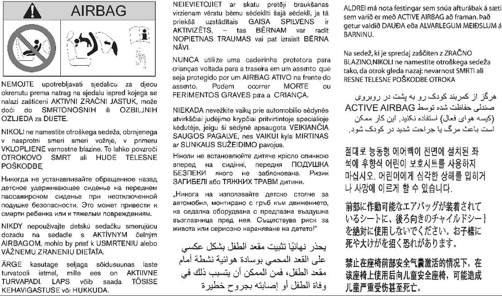
315
316 QUICK REFERENCE In case of emergency (Flat tyre, engine will not start, overheating, towing) How to start the engine How to read the meters and gauges Maintenance and do-it-yourself Technical information
317 SERVICE SHEETS (1/6) VIN:... Date: Km (Miles): Invoice number: Comments/miscellaneous Type of operation: Stamp Service... Anti-corrosion check: OK Not OK* *See specific page Date: Km (Miles): Invoice number: Comments/miscellaneous Type of operation: Stamp Service... Anti-corrosion check: OK Not OK* *See specific page Date: Km (Miles): Invoice number: Comments/miscellaneous Type of operation: Stamp Service... Anti-corrosion check: OK Not OK* *See specific page
318 SERVICE SHEETS (2/6) VIN:... Date: Km (Miles): Invoice number: Comments/miscellaneous Type of operation: Stamp Service... Anti-corrosion check: OK Not OK* *See specific page Date: Km (Miles): Invoice number: Comments/miscellaneous Type of operation: Stamp Service... Anti-corrosion check: OK Not OK* *See specific page Date: Km (Miles): Invoice number: Comments/miscellaneous Type of operation: Stamp Service... Anti-corrosion check: OK Not OK* *See specific page
319 SERVICE SHEETS (3/6) VIN:... Date: Km (Miles): Invoice number: Comments/miscellaneous Type of operation: Stamp Service... Anti-corrosion check: OK Not OK* *See specific page Date: Km (Miles): Invoice number: Comments/miscellaneous Type of operation: Stamp Service... Anti-corrosion check: OK Not OK* *See specific page Date: Km (Miles): Invoice number: Comments/miscellaneous Type of operation: Stamp Service... Anti-corrosion check: OK Not OK* *See specific page
320 SERVICE SHEETS (4/6) VIN:... Date: Km (Miles): Invoice number: Comments/miscellaneous Type of operation: Stamp Service... Anti-corrosion check: OK Not OK* *See specific page Date: Km (Miles): Invoice number: Comments/miscellaneous Type of operation: Stamp Service... Anti-corrosion check: OK Not OK* *See specific page Date: Km (Miles): Invoice number: Comments/miscellaneous Type of operation: Stamp Service... Anti-corrosion check: OK Not OK* *See specific page
321 SERVICE SHEETS (5/6) VIN:... Date: Km (Miles): Invoice number: Comments/miscellaneous Type of operation: Stamp Service... Anti-corrosion check: OK Not OK* *See specific page Date: Km (Miles): Invoice number: Comments/miscellaneous Type of operation: Stamp Service... Anti-corrosion check: OK Not OK* *See specific page Date: Km (Miles): Invoice number: Comments/miscellaneous Type of operation: Stamp Service... Anti-corrosion check: OK Not OK* *See specific page
322 SERVICE SHEETS (6/6) VIN:... Date: Km (Miles): Invoice number: Comments/miscellaneous Type of operation: Stamp Service... Anti-corrosion check: OK Not OK* *See specific page Date: Km (Miles): Invoice number: Comments/miscellaneous Type of operation: Stamp Service... Anti-corrosion check: OK Not OK* *See specific page Date: Km (Miles): Invoice number: Comments/miscellaneous Type of operation: Stamp Service... Anti-corrosion check: OK Not OK* *See specific page
323 ANTICORROSION CHECK (1/6) If the continuation of the warranty is subject to repair,itisindicated below. VIN:... Corrosion repair operation tobecarried out: Stamp Date ofrepair: Repair to be carried out: Stamp Date ofrepair: Repair to be carried out: Stamp Date ofrepair:
324 ANTICORROSION CHECK (2/6) If the continuation of the warranty is subject to repair,itisindicated below. VIN:... Corrosion repair operation tobecarried out: Stamp Date ofrepair: Repair to be carried out: Stamp Date ofrepair: Repair to be carried out: Stamp Date ofrepair:
325 ANTICORROSION CHECK (3/6) If the continuation of the warranty is subject to repair,itisindicated below. VIN:... Corrosion repair operation tobecarried out: Stamp Date ofrepair: Repair to be carried out: Stamp Date ofrepair: Repair to be carried out: Stamp Date ofrepair:
326 ANTICORROSION CHECK (4/6) If the continuation of the warranty is subject to repair,itisindicated below. VIN:... Corrosion repair operation tobecarried out: Stamp Date ofrepair: Repair to be carried out: Stamp Date ofrepair: Repair to be carried out: Stamp Date ofrepair:
327 ANTICORROSION CHECK (5/6) If the continuation of the warranty is subject to repair,itisindicated below. VIN:... Corrosion repair operation tobecarried out: Stamp Date ofrepair: Repair to be carried out: Stamp Date ofrepair: Repair to be carried out: Stamp Date ofrepair:
328 ANTICORROSION CHECK (6/6) If the continuation of the warranty is subject to repair,itisindicated below. VIN:... Corrosion repair operation tobecarried out: Stamp Date ofrepair: Repair to be carried out: Stamp Date ofrepair: Repair to be carried out: Stamp Date ofrepair:
329
330
331
 / Publication Number: OM18EN-0U60E0EUR / Printed in France")
332 RENAULT S.A.S. SOCIÉTÉ PAR ACTIONS SIMPLIFIÉE AU CAPITAL DE , QUAI LE GALLO BOULOGNE-BILLANCOURT R.C.S. NANTERRE SIRET TÉL. : Printing: August 2018 (01) / Publication Number: OM18EN-0U60E0EUR / Printed in France
BATTERY DISPOSAL. The NISSAN GREEN PROGRAM symbol indicates environmentally friendly information and best practices.
 ECO-MICRA The NISSAN GREEN PROGRAM symbol indicates environmentally friendly information and best practices. This symbol means Do not do this or Do not let this happen. BATTERY DISPOSAL CAUTION An improperly
10/2010 OM10E-0K13E0E
 NOTE Owner's Manual Foreword Welcome to the growing family of new NISSAN owners. This vehicle has been delivered to you with confidence. It has been produced using the latest techniques and strict quality
For your safety, read carefully and keep in this vehicle. Owner s Manual
 For your safety, read carefully and keep in this vehicle. Q50 Owner s Manual Foreword Welcome to the growing family of new INFINITI owners. This vehicle is delivered to you with confidence. It is produced
For your safety, read carefully and keep in this vehicle. Owner s Manual
 For your safety, read carefully and keep in this vehicle. QX70 Owner s Manual Foreword Welcome to the growing family of new INFINITI owners. This vehicle is delivered to you with confidence. It is produced
QASHQAI OWNER'S MANUAL
 QASHQAI OWNER'S MANUAL Foreword Welcome to the growing family of new NISSAN owners. This vehicle has been delivered to you with confidence. It has been produced using the latest techniques and strict quality
Foreword MODIFICATION OF YOUR VEHICLE IMPORTANT SAFETY INFORMATION REMINDERS FOR SAFETY! READ FIRST THEN DRIVE SAFELY WHEN READING THE MANUAL
 Foreword Welcome to the growing family of new INFINITI owners. This vehicle has been delivered to you with confidence. It has been produced using the latest techniques and strict quality control. This
WARNING IMPORTANT SAFETY INFORMA- TION REMINDERS FOR SAFETY!
 Foreword Welcome to the growing family of new NISSAN owners. This vehicle is delivered to you with confidence. It was produced using the latest techniques and strict quality control. This manual was prepared
InformationProvidedby:
 Foreword Welcome to the growing family of new NISSAN owners. This vehicle is delivered to you with confidence. It was produced using the latest techniques and strict quality control. This manual was prepared
2016 MICRA OWNER S MANUAL. For your safety, read carefully and keep in this vehicle.
 2016 MICRA OWNER S MANUAL For your safety, read carefully and keep in this vehicle. FOREWORD READ FIRST THEN DRIVE SAFELY Welcome to the growing family of new NISSAN owners. This vehicle is delivered to
2014 cube OWNER S MANUAL. InformationProvidedby: For your safety, read carefully and keep in this vehicle.
 2014 cube OWNER S MANUAL For your safety, read carefully and keep in this vehicle. WHEN READING THE MANUAL This manual includes information for all options available on this model. Therefore, you may
WARNING IMPORTANT SAFETY INFORMA- TION REMINDERS FOR SAFETY!
 Foreword Welcome to the growing family of new NISSAN owners. This vehicle is delivered to you with confidence. It was produced using the latest techniques and strict quality control. This manual was prepared
requirements, assisting you in the safe operation of your vehicle. WARNING IMPORTANT SAFETY INFORMA- TION REMINDERS FOR SAFETY!
 Foreword Welcome to the growing family of new NISSAN owners. This vehicle is delivered to you with confidence. It was produced using the latest techniques and strict quality control. This manual was prepared
2015 MICRA OWNER S MANUAL. For your safety, read carefully and keep in this vehicle.
 2015 MICRA OWNER S MANUAL For your safety, read carefully and keep in this vehicle. FOREWORD READ FIRST THEN DRIVE SAFELY Welcome to the growing family of new NISSAN owners. This vehicle is delivered to
Foreword MODIFICATION OF YOUR VEHICLE IMPORTANT SAFETY INFORMATION REMINDERS FOR SAFETY! READ FIRST THEN DRIVE SAFELY WHEN READING THE MANUAL
 Foreword Welcome to the growing family of new NISSAN owners. This vehicle has been delivered to you with confidence. It has been produced using the latest techniques and strict quality control. This manual
READ FIRST THEN DRIVE SAFELY
 FOREWORD READ FIRST THEN DRIVE SAFELY Welcome to the growing family of new NISSAN owners. This vehicle is delivered to you with confidence. It was produced using the latest techniques and strict quality
READ FIRST THEN DRIVE SAFELY
 FOREWORD READ FIRST THEN DRIVE SAFELY Welcome to the growing family of new NISSAN owners. This vehicle is delivered to you with confidence. It was produced using the latest techniques and strict quality
WARNING IMPORTANT SAFETY INFORMA- TION REMINDERS FOR SAFETY!
 Foreword Welcome to the growing family of new NISSAN owners. This vehicle is delivered to you with confidence. It was produced using the latest techniques and strict quality control. This manual was prepared
Thank you for choosing a Mazda. We at Mazda design and build vehicles with complete customer satisfaction in mind.
 J54L_8R34_EE_02H.BOOK Page 1 Monday, July 15, 2002 9:03 AM A Word to Mazda Owners Thank you for choosing a Mazda. We at Mazda design and build vehicles with complete customer satisfaction in mind. To help
READ FIRST THEN DRIVE SAFELY
 FOREWORD READ FIRST THEN DRIVE SAFELY Welcome to the growing family of new NISSAN owners. This vehicle is delivered to you with confidence. It was produced using the latest techniques and strict quality
2017 MICRA OWNER S MANUAL. For your safety, read carefully and keep in this vehicle.
 2017 MICRA OWNER S MANUAL For your safety, read carefully and keep in this vehicle. FOREWORD READ FIRST THEN DRIVE SAFELY Welcome to the growing family of new NISSAN owners. This vehicle is delivered to
READ FIRST THEN DRIVE SAFELY
 FOREWORD READ FIRST THEN DRIVE SAFELY Welcome to the growing family of new NISSAN owners. This vehicle is delivered to you with confidence. It was produced using the latest techniques and strict quality
READ FIRST THEN DRIVE SAFELY
 Foreword Your INFINITI represents a new way of thinking about vehicle design. It integrates advanced engineering and superior craftsmanship with a simple, refined aesthetic sensitivity associated with
READ FIRST THEN DRIVE SAFELY
 FOREWORD READ FIRST THEN DRIVE SAFELY Welcome to the growing family of new NISSAN owners. This vehicle is delivered to you with confidence. It was produced using the latest techniques and strict quality
READ FIRST THEN DRIVE SAFELY
 FOREWORD READ FIRST THEN DRIVE SAFELY Welcome to the growing family of new NISSAN owners. This vehicle is delivered to you with confidence. It was produced using the latest techniques and strict quality
READ FIRST THEN DRIVE SAFELY
 Foreword Welcome to the growing family of new NISSAN owners. This vehicle is delivered to you with confidence. It was produced using the latest techniques and strict quality control. This manual was prepared
READ FIRST THEN DRIVE SAFELY
 FOREWORD READ FIRST THEN DRIVE SAFELY Welcome to the growing family of new NISSAN owners. This vehicle is delivered to you with confidence. It was produced using the latest techniques and strict quality
READ FIRST THEN DRIVE SAFELY
 FOREWORD READ FIRST THEN DRIVE SAFELY Welcome to the growing family of new NISSAN owners. This vehicle is delivered to you with confidence. It was produced using the latest techniques and strict quality
READ FIRST THEN DRIVE SAFELY
 FOREWORD READ FIRST THEN DRIVE SAFELY Welcome to the growing family of new NISSAN owners. This vehicle is delivered to you with confidence. It was produced using the latest techniques and strict quality
READ FIRST THEN DRIVE SAFELY
 FOREWORD Your INFINITI represents a new way of thinking about vehicle design. It integrates advanced engineering and superior craftsmanship with a simple, refined aesthetic sensitivity associated with
READ FIRST THEN DRIVE SAFELY
 FOREWORD READ FIRST THEN DRIVE SAFELY Welcome to the growing family of new NISSAN owners. This vehicle is delivered to you with confidence. It was produced using the latest techniques and strict quality
2012 VERSA SEDAN OWNER S MANUAL. For your safety, read carefully and keep in this vehicle.
 2012 VERSA SEDAN OWNER S MANUAL For your safety, read carefully and keep in this vehicle. FOREWORD READ FIRST THEN DRIVE SAFELY Welcome to the growing family of new NISSAN owners. This vehicle is delivered
READ FIRST THEN DRIVE SAFELY
 FOREWORD READ FIRST THEN DRIVE SAFELY Welcome to the growing family of new NISSAN owners. This vehicle is delivered to you with confidence. It was produced using the latest techniques and strict quality
READ FIRST THEN DRIVE SAFELY
 FOREWORD READ FIRST THEN DRIVE SAFELY Welcome to the growing family of new NISSAN owners. This vehicle is delivered to you with confidence. It was produced using the latest techniques and strict quality
WARNING IMPORTANT SAFETY INFORMA- TION REMINDERS FOR SAFETY!
 Foreword Welcome to the growing family of new NISSAN owners. This vehicle is delivered to you with confidence. It was produced using the latest techniques and strict quality control. This manual was prepared
READ FIRST THEN DRIVE SAFELY
 FOREWORD READ FIRST THEN DRIVE SAFELY Welcome to the growing family of new NISSAN owners. This vehicle is delivered to you with confidence. It was produced using the latest techniques and strict quality
WARNING IMPORTANT SAFETY INFORMATION REMINDERS FOR SAFETY!
 Foreword Your INFINITI represents a new way of thinking about vehicle design. It integrates advanced engineering and superior craftsmanship with a simple, refined aesthetic sensitivity associated with
READ FIRST THEN DRIVE SAFELY
 Foreword Your INFINITI represents a new way of thinking about vehicle design. It integrates advanced engineering and superior craftsmanship with a simple, refined aesthetic sensitivity associated with
OWNER S MANUAL AND MAINTENANCE INFORMATION. For your safety, read carefully and keep in this vehicle.
 2018.5 OWNER S MANUAL AND MAINTENANCE INFORMATION For your safety, read carefully and keep in this vehicle. Owner s Manual Supplement The information contained within this supplement updates the following
READ FIRST THEN DRIVE SAFELY
 FOREWORD READ FIRST THEN DRIVE SAFELY Welcome to the growing family of new NISSAN owners. This vehicle is delivered to you with confidence. It was produced using the latest techniques and strict quality
For your safety, read carefully and keep in this vehicle Infiniti G Convertible Owner s Manual
 For your safety, read carefully and keep in this vehicle. 2011 Infiniti G Convertible Owner s Manual FOREWORD Your INFINITI represents a new way of thinking about vehicle design. It integrates advanced
For your safety, read carefully and keep in this vehicle Infiniti G37 Convertible Owner s Manual
 For your safety, read carefully and keep in this vehicle. 2010 Infiniti G37 Convertible Owner s Manual FOREWORD Your INFINITI represents a new way of thinking about vehicle design. It integrates advanced
READ FIRST THEN DRIVE SAFELY
 FOREWORD READ FIRST THEN DRIVE SAFELY Welcome to the growing family of new NISSAN owners. This vehicle is delivered to you with confidence. It was produced using the latest techniques and strict quality
2013 VERSA SEDAN OWNER S MANUAL. safety, read carefully and keep in this vehicle.
 2013 VERSA SEDAN OWNER S MANUAL For your safety, read carefully and keep in this vehicle. FOREWORD READ FIRST THEN DRIVE SAFELY Welcome to the growing family of new NISSAN owners. This vehicle is delivered
For your safety, read carefully and keep in this vehicle Infiniti EX Owner s Manual
 For your safety, read carefully and keep in this vehicle. 2011 Infiniti EX Owner s Manual FOREWORD Your INFINITI represents a new way of thinking about vehicle design. It integrates advanced engineering
READ FIRST THEN DRIVE SAFELY
 FOREWORD READ FIRST THEN DRIVE SAFELY Welcome to the growing family of new NISSAN owners. This vehicle is delivered to you with confidence. It was produced using the latest techniques and strict quality
READ FIRST THEN DRIVE SAFELY
 FOREWORD READ FIRST THEN DRIVE SAFELY Welcome to the growing family of new NISSAN owners. This vehicle is delivered to you with confidence. It was produced using the latest techniques and strict quality
InformationProvidedby:
 Foreword Welcome to the growing family of new NISSAN owners. This vehicle is delivered to you with confidence. It was produced using the latest techniques and strict quality control. This manual was prepared
requirements, assisting you in the safe operation of your vehicle. WARNING IMPORTANT SAFETY INFORMA- TION REMINDERS FOR SAFETY!
 Foreword Welcome to the growing family of new NISSAN owners. This vehicle is delivered to you with confidence. It was produced using the latest techniques and strict quality control. This manual was prepared
WARNING IMPORTANT SAFETY INFORMA- TION REMINDERS FOR SAFETY!
 Foreword Welcome to the growing family of new NISSAN owners. This vehicle is delivered to you with confidence. It was produced using the latest techniques and strict quality control. This manual was prepared
FOREWORD WARNING. of your vehicle.
 FOREWORD Your INFINITI represents a new way of thinking about vehicle design. It integrates advanced engineering and superior craftsmanship with a simple, refined aesthetic sensitivity associated with
2018 KICKS. OWNER S MANUAL and MAINTENANCE INFORMATION. For your safety, read carefully and keep in this vehicle.
 2018 KICKS OWNER S MANUAL and MAINTENANCE INFORMATION For your safety, read carefully and keep in this vehicle. CALIFORNIA PROPOSITION 65 WARNING WARNING Operating, servicing and maintaining a passenger
READ FIRST THEN DRIVE SAFELY
 FOREWORD READ FIRST THEN DRIVE SAFELY Welcome to the growing family of new NISSAN owners. This vehicle is delivered to you with confidence. It was produced using the latest techniques and strict quality
2010 TITAN OWNER'S MANUAL. For your safety, read carefully and keep in this vehicle.
 2010 TITAN OWNER'S MANUAL For your safety, read carefully and keep in this vehicle. FOREWORD READ FIRST THEN DRIVE SAFELY Welcome to the growing family of new NISSAN owners. This vehicle is delivered to
2010 PATHFINDER OWNER S MANUAL. For your safety, read carefully and keep in this vehicle.
 2010 PATHFINDER OWNER S MANUAL For your safety, read carefully and keep in this vehicle. FOREWORD READ FIRST THEN DRIVE SAFELY Welcome to the growing family of new NISSAN owners. This vehicle is delivered
2013 NV200 COMPACT CARGO
 2013 NV200 COMPACT CARGO OWNER S MANUAL For your safety, read carefully and keep in this vehicle. FOREWORD READ FIRST THEN DRIVE SAFELY Welcome to the growing family of new NISSAN owners. This vehicle
WARNING IMPORTANT SAFETY INFORMA- TION REMINDERS FOR SAFETY!
 Foreword Welcome to the growing family of new NISSAN owners. This vehicle is delivered to you with confidence. It was produced using the latest techniques and strict quality control. This manual was prepared
2012 XTERRA OWNER S MANUAL. For your safety, read carefully and keep in this vehicle. InformationProvidedby:
 2012 XTERRA OWNER S MANUAL For your safety, read carefully and keep in this vehicle. FOREWORD READ FIRST THEN DRIVE SAFELY Welcome to the growing family of new NISSAN owners. This vehicle is delivered
2010 MAXIMA OWNER S MANUAL. For your safety, read carefully and keep in this vehicle.
 2010 MAXIMA OWNER S MANUAL For your safety, read carefully and keep in this vehicle. FOREWORD READ FIRST THEN DRIVE SAFELY Welcome to the growing family of new NISSAN owners. This vehicle is delivered
READ FIRST THEN DRIVE SAFELY
 FOREWORD READ FIRST THEN DRIVE SAFELY Welcome to the growing family of new INFINITI owners. This vehicle is delivered to you with confidence. It was produced using the latest techniques and strict quality
2016 MAXIMA OWNER S MANUAL. For your safety, read carefully and keep in this vehicle.
 2016 MAXIMA OWNER S MANUAL For your safety, read carefully and keep in this vehicle. FOREWORD READ FIRST THEN DRIVE SAFELY Welcome to the growing family of new NISSAN owners. This vehicle is delivered
WARNING IMPORTANT SAFETY INFORMA- TION REMINDERS FOR SAFETY!
 Foreword Welcome to the growing family of new NISSAN owners. This vehicle is delivered to you with confidence. It was produced using the latest techniques and strict quality control. This manual was prepared
Black plate (27,1) Index 14 北米Model "A3180BE-B" EDITED: 2014/ 2/ 7
 Index 14 北米Model A3180BE-B EDITED: 2014/ 2/ 7") Index 14 14-2 Index A Abbreviation... 3 ABS (Anti-lock Brake System)... 7-20 Warning light... 3-15, 7-21 Accessories... 5-2, 11-36 Accessory power outlet... 6-10 Active head restraint... 1-6 Air cleaner
Index 14 14-2 Index A Abbreviation... 3 ABS (Anti-lock Brake System)... 7-20 Warning light... 3-15, 7-21 Accessories... 5-2, 11-36 Accessory power outlet... 6-10 Active head restraint... 1-6 Air cleaner
2010 XTERRA OWNER S MANUAL. For your safety, read carefully and keep in this vehicle. InformationProvidedby:
 2010 XTERRA OWNER S MANUAL For your safety, read carefully and keep in this vehicle. FOREWORD READ FIRST THEN DRIVE SAFELY Welcome to the growing family of new NISSAN owners. This vehicle is delivered
2012 NV1500/NV2500 HD/NV3500 HD
 2012 NV1500/NV2500 HD/NV3500 HD OWNER S MANUAL For your safety, read carefully and keep in this vehicle. FOREWORD READ FIRST THEN DRIVE SAFELY Welcome to the growing family of new NISSAN owners. This vehicle
2011 MAXIMA OWNER S MANUAL. For your safety, read carefully and keep in this vehicle. InformationProvidedby:
 2011 MAXIMA OWNER S MANUAL For your safety, read carefully and keep in this vehicle. FOREWORD READ FIRST THEN DRIVE SAFELY Welcome to the growing family of new NISSAN owners. This vehicle is delivered
READ FIRST THEN DRIVE SAFELY
 FOREWORD READ FIRST THEN DRIVE SAFELY Welcome to the growing family of new NISSAN owners. This vehicle is delivered to you with confidence. It was produced using the latest techniques and strict quality
SECTION 1 6 INSTRUMENTS AND CONTROLS. Comfort adjustment. Front seat... 42
 SECTION 1 6 INSTRUMENTS AND CONTROLS Comfort adjustment Front seat................................................ 42 Headrests............................................... 44 Tilt and telescopic steering
2011 XTERRA OWNER S MANUAL. For your safety, read carefully and keep in this vehicle.
 2011 XTERRA OWNER S MANUAL For your safety, read carefully and keep in this vehicle. FOREWORD READ FIRST THEN DRIVE SAFELY Welcome to the growing family of new NISSAN owners. This vehicle is delivered
READ FIRST THEN DRIVE SAFELY
 Foreword Your INFINITI represents a new way of thinking about vehicle design. It integrates advanced engineering and superior craftsmanship with a simple, refined aesthetic sensitivity associated with
2017 VERSA SEDAN. OWNER S MANUAL and MAINTENANCE INFORMATION. For your safety, read carefully and keep in this vehicle.
 2017 VERSA SEDAN OWNER S MANUAL and MAINTENANCE INFORMATION For your safety, read carefully and keep in this vehicle. FOREWORD READ FIRST THEN DRIVE SAFELY Welcome to the growing family of new NISSAN owners.
2015 VERSA SEDAN OWNER S MANUAL. For your safety, read carefully and keep in this vehicle.
 2015 VERSA SEDAN OWNER S MANUAL For your safety, read carefully and keep in this vehicle. FOREWORD READ FIRST THEN DRIVE SAFELY Welcome to the growing family of new NISSAN owners. This vehicle is delivered
2014 SENTRA OWNER S MANUAL. For your safety, read carefully and keep in this vehicle.
 2014 SENTRA OWNER S MANUAL For your safety, read carefully and keep in this vehicle. FOREWORD READ FIRST THEN DRIVE SAFELY Welcome to the growing family of new NISSAN owners. This vehicle is delivered
Owner s Manual Supplement
 Owner s Manual Supplement The information contained within this supplement revises the TIRE CHAINS information in the Maintenance and do-it-yourself section of the 2011-2013 Nissan Quest Owner s Manual.
2011 PATHFINDER OWNER S MANUAL. For your safety, read carefully and keep in this vehicle.
 2011 PATHFINDER OWNER S MANUAL For your safety, read carefully and keep in this vehicle. FOREWORD READ FIRST THEN DRIVE SAFELY Welcome to the growing family of new NISSAN owners. This vehicle is delivered
Child Safety ! WARNING: GENERAL SAFETY INFORMATION
 Child Safety GENERAL SAFETY INFORMATION Jaguar Cars Limited strongly recommends that at all times children should be carried in the rear seats.! WARNING: Children must be restrained by a child safety restraint
READ FIRST THEN DRIVE SAFELY
 FOREWORD READ FIRST THEN DRIVE SAFELY Welcome to the growing family of new NISSAN owners. This vehicle is delivered to you with confidence. It was produced using the latest techniques and strict quality
2011 VERSA OWNER S MANUAL. For your safety, read carefully and keep in this vehicle.
 2011 VERSA OWNER S MANUAL For your safety, read carefully and keep in this vehicle. FOREWORD READ FIRST THEN DRIVE SAFELY Welcome to the growing family of new NISSAN owners. This vehicle is delivered to
2017 VERSA NOTE. OWNER S MANUAL and MAINTENANCE INFORMATION. For your safety, read carefully and keep in this vehicle.
 2017 VERSA NOTE OWNER S MANUAL and MAINTENANCE INFORMATION For your safety, read carefully and keep in this vehicle. FOREWORD READ FIRST THEN DRIVE SAFELY Welcome to the growing family of new NISSAN owners.
Airbags SAFETY INFORMATION
 Airbags Your vehicle is equipped with several types of airbags: front airbags, front knee airbags, side airbags, and side curtain airbags. Front Airbags (SRS) The front SRS airbags inflate in a moderate-to-severe
Airbags SAFETY INFORMATION. Your vehicle is equipped with several types of airbags: front airbags, side airbags, and side curtain airbags.
 Airbags Your vehicle is equipped with several types of airbags: front airbags, side airbags, and side curtain airbags. Front Airbags (SRS) The front SRS airbags inflate in a moderate-to-severe frontal
2018 VERSA SEDAN. OWNER S MANUAL and MAINTENANCE INFORMATION. For your safety, read carefully and keep in this vehicle.
 2018 VERSA SEDAN OWNER S MANUAL and MAINTENANCE INFORMATION For your safety, read carefully and keep in this vehicle. FOREWORD READ FIRST THEN DRIVE SAFELY Welcome to the growing family of new NISSAN owners.
2011 ARMADA OWNER S MANUAL. For your safety, read carefully and keep in this vehicle. InformationProvidedby:
 2011 ARMADA OWNER S MANUAL For your safety, read carefully and keep in this vehicle. FOREWORD READ FIRST THEN DRIVE SAFELY Welcome to the growing family of new NISSAN owners. This vehicle is delivered
Index. Abbreviation list Alphabetical index What to do if
 Index Abbreviation list... 470 Alphabetical index... 471 What to do if...... 481 469 Abbreviation list Abbreviation/Acronym list ABBREVIATIONS ABS ACC ALR CRS DISP ECU EDR ELR GAWR GVWR I/M LATCH LED LSD
2010 Infiniti M35/M45 Owner's Manual
 2010 Infiniti M35/M45 Owner's Manual FOREWORD Your INFINITI represents a new way of thinking about vehicle design. It integrates advanced engineering and superior craftsmanship with a simple, refined aesthetic
2014 ROGUE OWNER S MANUAL. For your safety, read carefully and keep in this vehicle.
 2014 ROGUE OWNER S MANUAL For your safety, read carefully and keep in this vehicle. FOREWORD READ FIRST THEN DRIVE SAFELY Welcome to the growing family of new NISSAN owners. This vehicle is delivered to
READ FIRST THEN DRIVE SAFELY
 FOREWORD READ FIRST THEN DRIVE SAFELY Welcome to the growing family of new NISSAN owners. This vehicle is delivered to you with confidence. It was produced using the latest techniques and strict quality
2012 ALTIMA OWNER S MANUAL. For your safety, read carefully and keep in this vehicle.
 2012 ALTIMA OWNER S MANUAL For your safety, read carefully and keep in this vehicle. FOREWORD READ FIRST THEN DRIVE SAFELY Welcome to the growing family of new NISSAN owners. This vehicle is delivered
requirements, assisting you in the safe operation of your vehicle. WARNING IMPORTANT SAFETY INFORMA- TION REMINDERS FOR SAFETY!
 Foreword Welcome to the growing family of new NISSAN owners. This vehicle is delivered to you with confidence. It was produced using the latest techniques and strict quality control. This manual was prepared
2013 XTERRA OWNER S MANUAL. For your safety, read carefully and keep in this vehicle.
 2013 XTERRA OWNER S MANUAL For your safety, read carefully and keep in this vehicle. FOREWORD READ FIRST THEN DRIVE SAFELY Welcome to the growing family of new NISSAN owners. This vehicle is delivered
Index. Abbreviation list Alphabetical index What to do if
 Index Abbreviation list... 478 Alphabetical index... 479 What to do if...... 489 477 Abbreviation list Abbreviation/Acronym list ABBREVIATIONS ABS ACC ALR CRS DISP ECU EDR ELR GAWR GVWR I/M LATCH LED LSD
READ FIRST THEN DRIVE SAFELY
 Foreword Your INFINITI represents a new way of thinking about vehicle design. It integrates advanced engineering and superior craftsmanship with a simple, refined aesthetic sensitivity associated with
2018 PATHFINDER. OWNER S MANUAL and MAINTENANCE INFORMATION. For your safety, read carefully and keep in this vehicle.
 2018 PATHFINDER OWNER S MANUAL and MAINTENANCE INFORMATION For your safety, read carefully and keep in this vehicle. FOREWORD READ FIRST THEN DRIVE SAFELY Welcome to the growing family of new NISSAN owners.
2018 FRONTIER. OWNER S MANUAL and MAINTENANCE INFORMATION. For your safety, read carefully and keep in this vehicle.
 2018 FRONTIER OWNER S MANUAL and MAINTENANCE INFORMATION For your safety, read carefully and keep in this vehicle. FOREWORD READ FIRST THEN DRIVE SAFELY Welcome to the growing family of new NISSAN owners.
2018 VERSA NOTE. OWNER S MANUAL and MAINTENANCE INFORMATION. For your safety, read carefully and keep in this vehicle.
 2018 VERSA NOTE OWNER S MANUAL and MAINTENANCE INFORMATION For your safety, read carefully and keep in this vehicle. FOREWORD READ FIRST THEN DRIVE SAFELY This manual was prepared to help you understand
Z OWNER S MANUAL. InformationProvidedby: For your safety, read carefully and keep in this vehicle.
 2016 370Z OWNER S MANUAL For your safety, read carefully and keep in this vehicle. Foreword Welcome to the growing family of new NISSAN owners. This vehicle is delivered to you with confidence. It was
Seat, seatbelt and SRS airbags
 Front seats... 1-2 Manual seat (if equipped)... 1-3 Power seat (if equipped)... 1-4 Head restraint adjustment... 1-8 Seat heater (if equipped)... 1-8 Rear seats... 1-9 Reclining the seatback (Outback)...
READ FIRST THEN DRIVE SAFELY
 FOREWORD READ FIRST THEN DRIVE SAFELY Welcome to the growing family of new NISSAN owners. This vehicle is delivered to you with confidence. It was produced using the latest techniques and strict quality
READ FIRST THEN DRIVE SAFELY
 FOREWORD READ FIRST THEN DRIVE SAFELY Welcome to the growing family of new NISSAN owners. This vehicle is delivered to you with confidence. It was produced using the latest techniques and strict quality