For your safety, read carefully and keep in this vehicle. Owner s Manual
|
|
|
- Marshall Shaw
- 6 years ago
- Views:
Transcription
1 For your safety, read carefully and keep in this vehicle. QX70 Owner s Manual
2 Foreword Welcome to the growing family of new INFINITI owners. This vehicle is delivered to you with confidence. It is produced using the latest techniques and strict quality control. This manual was prepared to help you understand the operation and maintenance of your vehicle so that you may enjoy many kilometres (miles) of driving pleasure. Please read through this manual before operating your vehicle. A separate Warranty Information & Maintenance Booklet explains in detail the warranty coverage that applies to your vehicle. Your INFINITI Centre knows your vehicle best. When you require any service or have any questions, your INFINITI Centre will be glad to assist you with the extensive resources available for you. IMPORTANT SAFETY INFORMATION REMINDERS! Follow these important driving rules to help ensure a safe and complete trip for you and your passengers! NEVER drive under the influence of alcohol or drugs. ALWAYS observe posted speed limits and never drive too fast for conditions. ALWAYS use your seat belts and appropriate child restraint systems. Preteen children should be seated in the rear seat. ALWAYS provide information about the proper use of vehicle safety features to all occupants of the vehicle. ALWAYS review this Owner s Manual for important safety information. WHEN READING THE MANUAL This manual includes information for all options available on this model. Therefore, you may find some information that does not apply to your vehicle. Throughout this manual, some illustrations may only show the layout for Left-Hand Drive (LHD) models. For Right-Hand Drive (RHD) models, the illustrated shape and location of some components may differ. All information, specifications and illustrations in this manual are those in effect at the time of printing. INFINITI reserves the right to change specifications or designs at any time without notice and without obligation. MODIFICATION OF YOUR VEHICLE This vehicle should not be modified. Modifications could affect its performance, safety or durability, and may even violate governmental regulations. In addition, damage or performance problems resulting from modifications may not be covered under INFINITI warranties. READ FIRST THEN DRIVE SAFELY Before driving your vehicle, read this Owner s Manual carefully. This will ensure familiarity with controls and maintenance requirements, assisting you in the safe operation of your vehicle. Throughout this manual the following symbols and words are used: WARNING Indicates the presence of a hazard that could cause death or serious personal injury. To avoid or reduce the risk, the procedures described must be followed precisely. CAUTION Indicates the presence of a hazard that could cause minor or moderate personal injury, or damage to your vehicle. To avoid or reduce the risk, the procedures described must be followed carefully. NOTE Indicates additional helpful information.

3 Air bag warning labels: This symbol means Do not do this or Do not let this happen. Arrows in an illustration that are similar to these point to the front of the vehicle. Arrows in an illustration that are similar to these indicate movement or action. Arrows in an illustration that are similar to these call attention to an item in the illustration. [ ]: Square brackets are used to indicate messages, keys, or items displayed on a screen. < >: Chevrons or angle brackets are used to indicate texts on controls like buttons or switches inside or on the vehicle. NEVER use a rearward facing child restraint on a seat protected by an ACTIVE AIRBAG in front of it, DEATH or SERIOUS INJURY to the CHILD can occur. Be sure to read the Airbag warning labels description in the Safety section of this manual; and the Airbag label description at the end of this manual. ON-PAVEMENT AND OFF-ROAD DRIVING (4WD models) This vehicle will handle and manoeuvre differently from an ordinary passenger vehicle, because it has a higher centre of gravity. As with other vehicles with features of this type, failure to operate this vehicle correctly may result in loss of control or an accident. Be sure to read On-pavement and off-road driving precautions and Four-wheel drive (4WD) in the 5. Starting and driving section of this manual.

4 INFINITI Genuine Parts and Accessories might be branded either INFINITI or NISSAN BATTERY DISPOSAL CAUTION An improperly disposed battery can harm the environment. Always confirm local regulations for battery disposal. Examples of the batteries that the vehicle contains: Vehicle battery Remote controller battery (for Intelligent Key and/or Remote keyless entry system) Tyre Pressure Monitoring System (TPMS) sensor battery Remote controller battery (for Mobile Entertainment system) If in doubt, contact your local authority, or an INFINITI Centre, or a qualified workshop for advice on disposal. m Bluetooth is a trademark owned by Bluetooth SIG, Inc. ipod is a trademark of Apple Inc. m Gracenote and CDDB are registered trademarks of Gracenote, Inc. The Gracenote logo and logo type, and m the Powered by Gracenote logo are trademarks of Gracenote.
5 Contents Illustrated table of contents 0 Safety seats, seat belts and supplemental restraint system 1 Instruments and controls 2 Pre-driving checks and adjustments 3 Display screen, heater and air conditioner, and audio system 4 Starting and driving 5 In case of emergency 6 Appearance and care 7 Maintenance and do-it-yourself 8 Technical information 9 Index 10
6
7 0 Illustrated table of contents Seats, seat belts and Supplemental Restraint System (SRS) Exterior front Exterior rear Passenger compartment Cockpit Left-Hand Drive (LHD) model Right-Hand Drive (RHD) model Instrument panel Left-Hand Drive (LHD) model Right-Hand Drive (RHD) model Meters and gauges Engine compartment VK50VE engine model compartment cover removal VK50VE engine model VQ37VHR engine model V9X engine model
8 SEATS, SEAT BELTS AND SUPPLEMENTAL RESTRAINT SYSTEM (SRS) 11. Pre-tensioner seat belt system (P. 1-35) 12. Front seats (P. 1-2) Occupant classification sensors (weight sensors)* (P. 1-38) 13. Front passenger air bag status light* (P. 1-40) 14. Front passenger air bag switch (P. 1-42) *: where fitted NIC Child restraint anchorage* (P. 1-21) 2. Seat belts (P. 1-9) 3. Head restraints (P. 1-6) 4. Supplemental curtain side-impact air bags (P. 1-33) 5. Supplemental front-impact air bags (P. 1-33) 6. Front passenger air bag status light (P. 1-40, P. 1-42) 7. ISOFIX child restraint system (P. 1-21) 8. Rear armrest (P. 1-6) 9. Rear seats (P. 1-5) Child restraints (P. 1-14) 10. Supplemental side-impact air bags (P. 1-33) 0-2 Illustrated table of contents
9 EXTERIOR FRONT 1. Front view camera* (P. 4-26) 2. Bonnet (P. 3-20) 3. Headlights and turn signal lights (P. 2-27) Switch operation (P. 2-31) Adaptive Front lighting System (AFS)* (P. 2-28) Bulb replacement (P. 8-24) 4. Windscreen wipers and washers (P. 2-30) Switch operation (P. 2-30) Blade replacement (P. 8-16) Window washer fluid (P. 8-17) 5. Sunroof (P. 2-37) 6. Roof rack* (P. 2-46) 7. Power windows (P. 2-34) JVC0255X 8. Outside rearview mirrors (P. 3-27) Side view camera* (P. 4-26) Puddle light (P. 2-47) 9. Doors Keys (P. 3-2) Door locks (P. 3-4) Intelligent Key system (P. 3-7) Security system (P. 3-17) 10. Corner sensors (sonar) Parking sensor system* (P. 5-74) Around View Monitor* (P. 4-26) 11. Recovery hook (P. 6-13) 12. Centre sensors (sonar)* Parking sensor system* (P. 5-74) 13. Fog lights (P. 2-30) Switch operation (P. 2-30) Bulb replacement (P. 8-25) 14. Headlight cleaners* (P. 2-31, P. 2-29) 15. Tyres Tyres and wheels (P. 8-29) Flat tyre (P. 6-2) Specifications (P. 9-7) Tyre Pressure Monitoring System (TPMS)* (P. 5-3) Four-Wheel Drive (4WD) (P. 5-17) 16. Side turn signal lights (P. 2-29) Bulb replacement (P. 8-25) *: where fitted Illustrated table of contents 0-3
10 EXTERIOR REAR 7. Corner sensors (sonar) Parking sensor system* (P. 5-74) Around View Monitor* (P. 4-26) 8. Rear fog light Switch operation (P. 2-30) Bulb replacement (P. 8-25) 9. Centre sensors (sonar)* Parking sensor system* (P. 5-74) 10. Rear combination lights (Bulb replacement) (P. 8-25) 11. Fuel-filler lid (P. 3-25) Fuel information (P. 9-2) 12. Child safety rear door locks (P. 3-6) *: where fitted SSI Rear view camera* (P. 4-21, P. 4-26) 2. Back door (P. 3-20) Intelligent Key system (P. 3-7) Spare tyre (P. 6-2) or Emergency tyre puncture repair kit* (P. 6-6) 3. Rear window defogger (P. 2-33) 4. High-mounted stop light (Bulb replacement) (P. 8-25) 5. Rear window wiper and washer Switch operation (P. 2-32) Window washer fluid (P. 8-17) 6. Antenna (P. 4-57) 0-4 Illustrated table of contents
11 PASSENGER COMPARTMENT 11. Battery (for V9X engine model) (P. 3-18) 12. Cargo cover (P. 2-43) 13. Rear cup holders (P. 2-42) 14. Console box (P. 2-41) Power outlet (P. 2-39) Auxiliary sockets (P. 4-84) USB connection port* (P. 4-68) ipod player operation P. 4-74) 15. Front cup holders (P. 2-42) 16. Cancel switch for ultrasonic and tilt sensor (theft warning system) (P. 2-18) *: where fitted JVC0289X 1. Coat hooks (P. 2-43) 2. Rear personal lights (P. 2-48) 3. Mobile Entertainment System (MES)* (P. 4-85) 4. Door armrest Power window controls (P. 2-34) Power door lock switch (P. 3-5) 5. Automatic drive positioner switch (P. 3-29) 6. Sun visors (P. 2-47) 7. Sunroof switch (P. 2-37) 8. Map lights (P. 2-48) 9. Sunglasses holder* (P. 2-42) 10. Inside rearview mirror (P. 3-27) Illustrated table of contents 0-5
12 COCKPIT LEFT-HAND DRIVE (LHD) MODEL 1. Outside rearview mirror remote control switch (P. 3-27) 2. Headlight cleaner switch* (P. 2-29) or Intelligent Brake Assist (IBA) OFF switch* (P. 5-69) 3. Power back door switch (P. 3-20) 4. Power back door main switch (P. 3-20) 5. Instrument brightness control switch (P. 2-4) JVC0177XZ 6. Headlight, fog light and turn signal switch Headlight (P. 2-27) Turn signal (P. 2-29) Fog light (P. 2-30) 7. Steering-wheel-mounted controls (left side) Audio control steering switch (P. 4-83) Hands-Free Phone System switch* (Type A* (P. 4-93), Type B* (P ), or Type C* (P )) 8. Trip computer switch (P. 2-23) 9. Wiper and washer switch (P. 2-30) 10. Steering-wheel-mounted controls (right side) Cruise control (P. 5-31) Intelligent Cruise Control (ICC) system* (P. 5-33) Lane Departure Prevention (LDP) system* (P. 5-25) Speed limiter* (P. 5-29) 11. Shift lever (P. 5-13) 12. Parking sensor system OFF switch* (P. 5-76) or Warning systems switch* Forward Collision Warning (FCW) (P. 5-66) Lane Departure Warning (LDW) (P. 5-23) 13. Vehicle Dynamic Control (VDC) OFF switch* (P. 5-19) or Electronic Stability Programme (ESP) OFF switch* (P. 5-22) 14. Intelligent Key port Intelligent Key battery discharge (P. 5-11) Intelligent Key battery replacement (P. 8-20) 0-6 Illustrated table of contents
13 15. TRIP/RESET switch for twin trip odometer (P. 2-2) 16. Electric tilting/telescopic steering wheel switch* (P. 3-26) 17. Control switches Climate controlled seat switches* (P. 1-4) SNOW mode switch* (P. 5-18) Continuous damping control mode select switch* (P. 5-19) *: where fitted Illustrated table of contents 0-7
14 RIGHT-HAND DRIVE (RHD) MODEL 1. Shift lever (P. 5-13) 2. Steering-wheel-mounted controls (left side) Audio control steering switch (P. 4-83) Hands-Free Phone System switch (Type A* (P. 4-93), Type B* (P ), or Type C* (P )) JVC0650X 3. Headlight, fog light and turn signal switch Headlight (P. 2-27) Turn signal (P. 2-29) Fog light (P. 2-30) 4. Instrument brightness control switch (P. 2-4) 5. Steering-wheel-mounted controls (right side) Cruise control (P. 5-31) Intelligent Cruise Control (ICC) system* (P. 5-33) Lane Departure Prevention (LDP) system* (P. 5-25) Speed limiter* (P. 5-29) 6. Wiper and washer switch (P. 2-30) 7. Trip computer switch (P. 2-23) 8. Power back door main switch (P. 3-21) 9. Power back door switch (P. 3-20) 10. Intelligent Brake Assist (IBA) OFF switch* (P. 5-69) 11. Outside rearview mirror remote control switch (P. 3-27) 12. Control switches Climate controlled seat switches* (P. 1-4) SNOW mode switch* (P. 5-18) Continuous damping control mode select switch* (P. 5-19) 13. Electric tilting/telescopic steering wheel switch (P. 3-26) 14. TRIP/RESET switch for twin trip odometer (P. 2-2) 0-8 Illustrated table of contents
15 15. Intelligent Key port Intelligent Key battery discharge (P. 5-11) Intelligent Key battery replacement (P. 8-20) 16. Vehicle Dynamic Control (VDC) OFF switch* (P. 5-19) or Electronic Stability Programme (ESP) OFF switch* (P. 5-22) 17. Parking sensor system OFF switch* (P. 5-76) or Warning systems switch* Forward Collision Warning (FCW) (P. 5-66) Lane Departure Warning (LDW) (P. 5-23) *: where fitted Illustrated table of contents 0-9
16 INSTRUMENT PANEL LEFT-HAND DRIVE (LHD) MODEL 1. Side vents (P. 4-41) 2. Paddle shifter* (P. 5-15) 3. Meters and gauges (P. 2-2) 4. Centre vents (P. 4-41) 5. Centre multi-function control panel (P. 4-3) Vehicle information and setting buttons (P. 4-7) Audio system (P. 4-47) 6. Centre display Around View Monitor (P. 4-26) SSI0457 Rear view monitor* (P. 4-21) Navigation system* (Refer to the separately the provided Navigation System Owner s Manual.) 7. Clock (P. 2-38) 8. Hazard warning flasher switch (P. 6-2) 9. Front passenger s supplemental frontimpact air bag (P. 1-33) 10. Bonnet release handle (P. 3-20) 11. Fuse box cover (P. 8-23) 12. Parking brake pedal Operation (P. 3-29) Check (P. 8-13) 13. Steering wheel Horn (P. 2-34) Driver s supplemental front-impact air bag (P. 1-33) Power steering system (P. 5-78) 14. Push-button ignition switch (P. 5-9) 15. Door lock indicator light* (P. 3-5) 16. Ashtrays and cigarette lighter (P. 2-40) 17. Defogger switch/de-icer switch* (P. 2-33) 18. Heater and air conditioner (P. 4-42) 19. Audio system (P. 4-47) 20. Glove box lid release handle (P. 2-40) *: where fitted 0-10 Illustrated table of contents
17 RIGHT-HAND DRIVE (RHD) MODEL 1. Front passenger s supplemental frontimpact air bag (P. 1-33) 2. Centre multi-function control panel (P. 4-3) Vehicle information and setting buttons (P. 4-7) Audio system (P. 4-47) JVC0655X 3. Clock (P. 2-38) 4. Centre display Around View Monitor* (P. 4-26) Rear view monitor* (P. 4-21) Navigation system* (Refer to the separately provided Navigation System Owner s Manual.) 5. Hazard warning flasher switch (P. 6-2) 6. Centre vents (P. 4-41) 7. Meters and gauges (P. 2-2) 8. Paddle shifter* (P. 5-15) 9. Side vents (P. 4-41) 10. Glove box lid release handle (P. 2-40) 11. Audio system (P. 4-47) 12. Heater and air conditioner (P. 4-42) 13. Door lock indicator light* (P. 3-5) 14. Defogger switch (P. 2-33) 15. Ashtrays and cigarette lighter (P. 2-40) 16. Push-button ignition switch (P. 5-9) 17. Parking brake pedal Operation (P. 3-29) Check (P. 8-13) 18. Steering wheel Horn (P. 2-34) Driver s supplemental front-impact air bag (P. 1-33) Power steering system (P. 5-78) 19. Fuse box cover (P. 8-23) 20. Bonnet release handle (P. 3-20) *: where fitted Illustrated table of contents 0-11
18 METERS AND GAUGES SIC Tachometer (P. 2-2) 2. Warning/Indicator lights (P. 2-6) 3. Speedometer (P. 2-2) 4. Engine coolant temperature gauge (P. 2-3) 5. Vehicle information display (P. 2-17) Odometer/twin trip odometer (P. 2-2) 6. Fuel gauge (P. 2-3) 0-12 Illustrated table of contents
19 ENGINE COMPARTMENT SDI2263 VK50VE ENGINE MODEL COMPARTMENT COVER REMOVAL To remove the engine compartment covers, unhook the clips ja located as illustrated. To remove the engine cover, pull the cover upward first j1 and then toward the front of the vehicle j2. Illustrated table of contents 0-13
20 11. Engine coolant reservoir (P. 8-6) * The layout illustrated is for the Left-Hand Drive (LHD) model. On the Right-Hand Drive (RHD) model, these components are located on the opposite side. SDI2321 VK50VE ENGINE MODEL 1. Fuse/fusible link holder* (P. 8-21) 2. Battery* (P. 8-18) Jump starting (P. 6-10) 3. Engine oil filler cap (P. 8-7) 4. Radiator filler cap (P. 8-6) Vehicle overheat (P. 6-12) 5. Engine oil dipstick (P. 8-7) 6. Brake fluid reservoir* (P. 8-14) 7. Window washer fluid reservoir (P. 8-17) 8. Power steering fluid reservoir (P. 8-15) 9. Air cleaner (P. 8-15) 10. Drive belt location (P. 8-11) 0-14 Illustrated table of contents
21 11. Engine coolant reservoir (P. 8-6) * The layout illustrated is for the Left-Hand Drive (LHD) model. On the Right-Hand Drive (RHD) model, these components are located on the opposite side. SDI2280 VQ37VHR ENGINE MODEL 1. Fuse/fusible link holder* (P. 8-21) 2. Battery* (P. 8-18) Jump starting (P. 6-10) 3. Radiator filler cap (P. 8-6) Vehicle overheat (P. 6-12) 4. Engine oil dipstick (P. 8-7) 5. Engine oil filler cap (P. 8-7) 6. Brake fluid reservoir* (P. 8-14) 7. Window washer fluid reservoir (P. 8-17) 8. Power steering fluid reservoir (P. 8-15) 9. Air cleaner (P. 8-15) 10. Drive belt location (P. 8-11) Illustrated table of contents 0-15
22 10. Engine coolant reservoir (P. 8-6) The battery is located under the luggage room. (See Battery in the 8. Maintenance and do-ityourself section.) *: The layout illustrated is for the Left- Hand Drive (LHD) model. On the Right- Hand Drive (RHD) model, these components are located on the opposite side. SSI0741 V9X ENGINE MODEL 1. Engine oil dipstick (P. 8-7) 2. Air cleaner (P. 8-15) 3. Engine oil filler cap (P. 8-7) 4. Brake fluid reservoir* (P. 8-14) 5. Fuse/fusible link holder (P. 8-21) Jump starting (P. 6-10) 6. Window washer fluid reservoir (P. 8-17) 7. Power steering fluid reservoir (P. 8-15) 8. Radiator filler cap (P. 8-6) Vehicle overheat (P. 6-12) 9. Drive belt location (P. 8-11) 0-16 Illustrated table of contents
23 1 Safety seats, seat belts and supplemental restraint system Seats Front seats Rear seats Armrest Head restraints Adjustable head restraint components Non-adjustable head restraint components Remove Install Adjust Active head restraints Seat belts Precautions on seat belt usage Child safety Pregnant women Injured persons CENTER mark on seat belts (where fitted) Three-point type seat belts Seat belt maintenance Child restraints Precautions on child restraints usage Universal child restraints for front seat and rear seats ISOFIX child restraint system Child restraint anchorage Child restraint installation using ISOFIX (for rear seat) Installation of child restraint system using three point type seat belt Supplemental Restraint System (SRS) Precautions on Supplemental Restraint System (SRS) Supplemental air bag systems Pre-tensioner seat belt system Repair and replacement procedure
24 SEATS WARNING Do not drive and/or ride in the vehicle with the seatback reclined. This can be dangerous. The shoulder belt will not be properly against the body. In an accident, you and your passengers could be thrown into the shoulder belt and receive neck or other serious injuries. You and your passengers could also slide under the lap belt and receive serious injuries. For the most effective protection while the vehicle is in motion, the seatback should be upright. Always sit well back and upright in the seat and adjust the seat properly. (See Seat belts later in this section.) Do not leave children unattended inside the vehicle. They could unknowingly activate switches or controls, or move the vehicle. Unattended children could become involved in serious accidents. To help avoid risk of injury or death through unintended operation of the vehicle and/or its systems, do not leave children, people who require the assistance of others or pets unattended in your vehicle. Additionally, the temperature inside a closed vehicle on a warm day can quickly become high enough to cause a significant risk of injury or death to people and pets. CAUTION When adjusting the seat positions, be sure not to contact any moving parts to avoid possible injuries and/ or damages. FRONT SEATS WARNING SSS0133AZ Do not adjust the driver s seat while driving so that full attention may be given to vehicle operation. Power seat adjustment Operating tips: The power seat motor has an auto-reset overload protection circuit. Ifthe motor stopsduring the seat adjustment, wait 30 seconds, then reactivate the switch. To avoid discharge of the battery, do not operate the power seats for a long period of time when the engine is not running. For the automatic drive positioner operation, see Automatic drive positioner in the 3. Pre-driving checks and adjustments section. 1-2 Safety seats, seat belts and supplemental restraint system
25 Seat lifter (where fitted): 1. Pull the adjusting switch up or push it down to adjust the seat height until the desired position is achieved. 2. Tilt the adjusting switch up or down to adjust the front angle of the seat until the desired position is achieved. SSS1051Z Forward and backward: Move the adjusting switch j1 forward or backward to the desired position. Reclining: Move the adjusting switch j2 forward or backward to the desired position. The reclining feature allows the adjustment of the seatback for occupants of different sizes to help obtain the proper seat belt fit. (See Seat belts later in this section.) The seatbackmay be reclined to allow occupants to rest when the vehicle is parked. WARNING The seatback should not be reclined any more than needed for comfort. Seat belts are most effective when the passenger sits well back and straight up in the seat. If the seatback is reclined, the risk of sliding under the lap belt and being injured is increased. SSS1053Z Lumbar support: The lumbar support feature provides lower back support to the driver. Push each side of the adjusting switch to adjust the seat lumbar area until the desired position is achieved. SSS1052Z Safety seats, seat belts and supplemental restraint system 1-3
26 SSS0685Z Side support (where fitted): The side support feature provides thigh and torso supports. Push the switch inside j1 or outside j2 to adjust the thigh area. Push the switch inside j3 or outside j4 to adjust the torso area. SSS0893Z Thigh extension (where fitted): The front portion of the front seats can be extended forward for seating comfort. Pull up and hold the lever j1 to extend the front portion to the desired position. SSS0905Z Climate controlled seats The climate controlled seat warms up or cools down the front seats by blowing warm or cool air from the surface of the seat. The switches located on the centre console can be operated independently of each other. 1. Start the engine. 2. Turn the control knob ja to the heat side j1 or to the cool side j2. The indicator light jb on the control knob will illuminate. 3. Adjust the desired temperature of the air using the control knob ja. The amount of air will be adjusted automatically. When the control knob is turned to the cool side, the air will flow harder in the beginning to cool faster. 4. When the vehicle s interior is warmed or cooled, and/or before you leave the vehicle, be sure to turn the control knob to the OFF position (centre). The indicator light jb on the control knob turns off at the OFF position. To check the air filter for the climate controlled seat, contact an INFINITI Centre or qualified workshop. CAUTION The battery could run down if the climate controlled seat is operated while the engine is not running. Do not use the climate controlled seat for extended periods or when no one is using the seat. Do not put anything on the seat which insulates heat, such as a blanket, cushion, seat cover, etc. Otherwise, the seat may become overheated. Do not place anything hard or heavy on the seat or pierce it with a pin or similar object. This may result in damage to the climate controlled seat. Any liquid spilled on the seat should be removed immediately with a dry cloth. 1-4 Safety seats, seat belts and supplemental restraint system
27 The climate controlled seat has an air filter. Do not operate climate controlled seat without an air filter. This may result in damage to the system. When cleaning the seat, never use petrol, thinner, or any similar materials. If any malfunctions are found or the climate controlled seat does not operate, turn the switch off and have the system checked by an INFINITI Centre or qualified workshop. REAR SEATS WARNING Never allow anyone to ride in the cargo area or on the rear seat when it is in the fold-down position. Use of these areas by passengers without proper restraints could result in serious injury or death in an accident or sudden stop. Properly secure all cargo with ropes or straps to help prevent it from sliding or shifting. Do not place cargo higher than the seatbacks. In a sudden stop or collision, unsecured cargo could cause personal injury. When returning the seatbacks to the upright position, be certain they are completely secured in the latched position. If they are not completely secured, passengers may be injured in an accident or sudden stop. SSS0894Z Reclining Pull the reclining lever ja and position the seatback at the desired angle. Release the reclining lever after positioning the seat at the desired angle. To return the seatback, pull the lever. The reclining feature allows adjustment of the seatback for occupants of different sizes to help obtain proper seat belt fit. (See Precautions on seat belt usage later in this section.) The seatback may also be reclined to allow occupants to rest when the vehicle is parked. WARNING Do not ride in a moving vehicle when the seatback is reclined. This can be dangerous. The shoulder belt will not be against your body. In an accident, you could be thrown into it and receive neck or other serious injuries. You could also slide under the lap belt and receive serious internal injuries. For the most effective protection when the vehicle is in motion, the seat should be upright. Always sit well back and upright in the seat with both feet on the floor and adjust the seat belt properly. See Precautions on seat belt usage later in this section. After adjustment, check to be sure the seat is securely locked. Folding SSS0895Z Before folding the rear seats: Remove drink containers from the rear cup holder. To fold down the seatbacks: Pull the lever ja or jb and fold the seatback. Return the rear seatback manually until it securely locks in position. Safety seats, seat belts and supplemental restraint system 1-5
28 HEAD RESTRAINTS ARMREST Rear SSS0901Z Pull the tab and draw the armrest forward until it is horizontal. WARNING Head restraints supplement the other vehicle safety systems. They may provide additional protection against injury in certain rear end collisions. Adjust the head restraints properly, as specified in this section. Check the adjustment after someone else uses the seat. Do not attach anything to the head restraint stalks or remove the head restraint. Do not use the seat if the head restraint has been removed. If the head restraint was removed, reinstall and properly adjust the head restraint before an occupant uses the seating position. Failure to follow these instructions can reduce the effectiveness of the head restraints. This may increase the risk of serious injury or death in a collision. Your vehicle is equipped with head restraints that may be integrated, adjustable or non-adjustable. Adjustable head restraints have multiple notches along the stalk to lock them in a desired adjustment position. The non-adjustable head restraints have a single locking notch to secure them to the seat frame. Proper Adjustment: For the adjustable type, align the head restraint so the centre of your ear is approximately level with the centre of the head restraint. If your ear position is still higher than the recommended alignment, place the head restraint at the highest position. If the head restraint has been removed, ensure that it is reinstalled and locked in place before riding in that designated seating position. ADJUSTABLE HEAD RESTRAINT COMPONENTS 1. Removable head restraint 2. Multiple notches 3. Lock knob 4. Stalks SSS0992Z 1-6 Safety seats, seat belts and supplemental restraint system


29 NON-ADJUSTABLE HEAD RESTRAINT COMPONENTS REMOVE INSTALL 1. Removable head restraint 2. Single notch 3. Lock knob 4. Stalks JVR0203XZ SSS1037Z Use the following procedure to remove the head restraint. 1. Pull the head restraint up to the highest position. 2. Push and hold the lock knob. 3. Remove the head restraint from the seat. 4. Store the head restraint properly in a secure place so it is not loose in the vehicle. 5. Reinstall and properly adjust the head restraint before an occupant uses the seating position. SSS1038Z 1. Align the head restraint stalks with the holes in the seat. Make sure that the head restraint is facing the correct direction. The stalk with the adjustment notch j1 must be installed in the hole with the lock knob j2. 2. Push and hold the lock knob and push the head restraint down. 3. Properly adjust the head restraint before an occupant uses the seating position. Safety seats, seat belts and supplemental restraint system 1-7


30 ADJUST the lock knob is engaged in the notch before riding in that designated seating position. Raise Lower SSS0997Z SSS1036Z For adjustable head restraint Adjust the head restraint so the centre is level with the centre of your ears. If your ear position is still higher than the recommended alignment, place the head restraint at the highest position. SSS1035Z To raise the head restraint, pull it up. Make sure the head restraint is positioned from the stored position or any non-latch position so the lock knob is engaged in the notch before riding in that designated seating position. To lower, push and hold the lock knob and push the head restraint down. Make sure the head restraint is positioned so the lock knob is engaged in the notch before riding in that designated seating position. JVR0259XZ For non-adjustable head restraint Make sure the head restraint is positioned from the stored position or any non-latch position so 1-8 Safety seats, seat belts and supplemental restraint system
31 SEAT BELTS ACTIVE HEAD RESTRAINTS Active head restraints are effective to provide protection at low to medium speeds in which whiplash injury seems to occur most. Active head restraints operate only in certain rear-end collisions. After the collision, the head restraints return to their original positions. Properly adjust the active head restraints as described in the previous section. PRECAUTIONS ON SEAT BELT USAGE Ifyou are wearing the seat belt properly adjusted and sitting upright and well back in the seat, chances of being injured or killed in an accident and/or the severity of injury may be greatly reduced. INFINITI strongly encourages you and all of your passengers to buckle up every time you drive, even if your seating position includes the supplemental air bag systems. SSS0508Z WARNING Failure to adjust the head restraint properly may reduce the effectiveness of the active head restraint. Always adjust the head restraint as described earlier in this section. Do not attach anything to the head restraint stalks. Doing so could impair the active head restraint function. Always wear seat belts. Active head restraints are designed to supplement other safety systems. No system can prevent all injuries in any accident. The active head restraint moves forward utilising the force that the seatback receives from the occupant in a rear-end collision. The movement of the head restraint helps support the front occupant s head by reducing its backward movement and helps absorb some of the forces that may lead to whiplash type injuries. Safety seats, seat belts and supplemental restraint system 1-9
32 SSS0134AZ SSS0014Z SSS0136AZ SSS0016Z 1-10 Safety seats, seat belts and supplemental restraint system
33 WARNING Seatbelts are designed to bear upon the bony structure of the body, and should be worn low across the front of the pelvis or the pelvis, chest and shoulders, as applicable; wearing the lap section of the belt across the abdominal area must be avoided. Serious injury may occur if a seat belt is not worn properly. Position the lap belt as low and snug as possible around the hips, not the waist. A lap belt worn too high could increase the risk of internal injuries in an accident. Do not allow more than one person to use the same seat belt. Each belt assembly must only be used by one occupant; it is dangerous to put a belt around a child being carried on the occupant s lap. Never carry more people in the vehicle than there are seat belts. Never wear seat belts inside out. Belts should not be worn with straps twisted. Doing so may reduce their effectiveness. Seatbelts should be adjusted as firmly as possible, consistent with comfort, to provide the protection for which they have been designed. A slack belt will greatly reduce the protection afforded to the wearer. Every person who drives or rides in this vehicle should use a seat belt at all times. Children should be in the rear seats and in an appropriate restraint. Do not put the belt behind your back or under your arm. Always route the shoulder belt over your shoulder and across your chest. The belt should be away from your face and neck, but not falling off your shoulder. Serious injury may occur if a seat belt is not worn properly. No modifications or additions should be made by the user which will either prevent the seat belt adjusting devices from operating to remove slack, or prevent the seat belt assembly from being adjusted to remove slack. Care should be taken to avoid contamination of the webbing with polishes, oilsand chemicals, and particularly battery acid. Cleaning may safely be carried out using mild soap and water. The belt should be replaced if webbing becomes frayed, contaminated or damaged. It is essential to replace the entire assembly after it has been worn in a severe impact even if damage to the assembly is not obvious. All seat belt assemblies including retractors and attaching hardware should be inspected after any collision by an INFINITI Centre or qualified workshop. INFINITI recommends that all seat belt assemblies in use during a collision be replaced unless the collision was minor and the belts show no damage and continue to operate properly. Seat belt assemblies not in use during a collision should also be inspected and, when necessary, replaced if either damage or improper operation is noted. Once the pretensioner seat belt has activated, it cannot be reused. It must be replaced together with the retractor. Contact an INFINITI Centre or qualified workshop. Removal and installation of the pretensioner seat belt system components should be done by an INFINITI Centre or qualified workshop. CHILD SAFETY WARNING Infants and children need special protection. The vehicle s seat belts may not fit them properly. The shoulder belt may come too close to the face or neck. The lap belt may not fit over their small hipbones. In an accident, an improperly fitted seat belt could cause serious or fatal injury. Always use an appropriate child restraint system. Children need adults to help protect them. They need to be properly restrained. The proper restraint depends on the child s size. Safety seats, seat belts and supplemental restraint system 1-11
34 Infants and small children SSS0099Z INFINITI recommends that infants and small children be seated in a child restraint system. You should choose a child restraint system that fits your vehicle and the child, and always follow the manufacturer s instructions for installation and use. Large children WARNING Never allow children to stand or kneelon anyseats. Never allow children in the luggage areas while the vehicle is moving. A child could be seriously injured in an accident or sudden stop. Children who are too large for a child restraint system should be seated and restrained by the seat belts that are provided. If the child s seating position has a shoulder belt that fits close to the face or neck, the use of a booster seat (commercially available) may help overcome this. The booster seat should raise the child so that the shoulder belt is properly positioned across the top, middle portion of the shoulder and the lap belt is low on the hips. The booster seat should also fit the vehicle seat. Once the child has grown so that the shoulder belt is no longer on or near the face or neck of the child, use the shoulder belt without the booster seat. In addition, there are many types of child restraint systems available for larger children that should be used for maximum protection. PREGNANT WOMEN INFINITI recommends that pregnant women use seat belts. The seat belt should be worn snug, and always position the lap belt as low as possible around the hips, not the waist. Place the shoulder belt over your shoulder and across your chest. Never run the lap/shoulder belt over your abdominal area. Contact your doctor for specific recommendations. INJURED PERSONS INFINITI recommends that injured persons use seat belts. Contact your doctor for specific recommendations. CENTER MARK ON SEAT BELTS (where fitted) Selecting correct set of seat belts The centre seat belt buckle is identified by the CENTER mark. The centre seat belt tongue can be fastened only into the centre seat belt buckle. THREE-POINT TYPE SEAT BELTS SSS0671Z SSS0292Z 1-12 Safety seats, seat belts and supplemental restraint system
35 Fastening seat belts WARNING The seatback should not be in a reclined position any more than needed for comfort. Seat belts are most effective when the passenger sits well back and straight up in the seat. 1. Adjust the seat. (See Seats earlier in this section.) 2. Slowly pull the seat belt out of the retractor and insert the tongue into the buckle until you hear and feel the latch engage. The retractor is designed to lock during a sudden stop or on impact. A slow pulling motion permits the seat belt to move, and allows you some freedom of movement in the seat. If the seat belt cannot be pulled from its fully retracted position, firmly pull the belt and release it. Then smoothly pull the belt out of the retractor. SSS0467Z 3. Position the lap belt portion low and snug on the hips as shown. 4. Pull the shoulder belt portion toward the retractor to take up extra slack. Be sure the shoulder belt is routed over your shoulder and is snug across your chest. SSS0896Z Shoulder belt height adjustment WARNING The shoulder belt anchor height should be adjusted to the position best for you. Failure to do so may reduce the effectiveness of the entire restraint system and increase the chance or severity of injury in an accident. The shoulder belt should rest on the middle of the shoulder. It must not rest against the neck. Be sure that the seat belt is not twisted in any way. Be sure that the shoulder belt anchor is secured by trying to move the shoulder belt anchor up and down after adjustment. To adjust, push in the release button ja and move the shoulder belt anchor to the proper position, so that the belt passes over the centre of the shoulder. The belt should be away from your face and neck, but not falling off your shoulder. Release the button to lock the shoulder belt anchor into position. Unfastening seat belts Push the button on the buckle. The seat belt automatically retracts. Safety seats, seat belts and supplemental restraint system 1-13
36 CHILD RESTRAINTS Automatic locking mode (where fitted) The front passenger and rear three-point seat belts have an automatic lock mechanism to use when installing a child restraint system. This mechanism is referred to as the automatic locking mode. If the seat belt is fully extended, the automatic lock mechanism will be activated and the seat belt can only retract. The seat belt will not be able to extend unless the seat belt is fully retracted once. To deactivate the automatic locking mode, detach the seat belt tongue from the buckle and fully retract the belt to its storing position. CAUTION The automatic locking mode should be used only for installation of a child restraint system. During normal seat belt use by a passenger, the automatic locking mode should not be activated. The use of the automatic locking mode by a passenger may cause uncomfortable seat belt tension. It can also change the operation of the front passenger air bag. (See Supplemental Restraint System (SRS) later in this section.) Checking seat belt operation Seat belt retractors are designed to lock seat belt movement: When the seat belt is pulled quickly from the retractor. When the vehicle slows down rapidly. To increase your confidence in the seat belts, check the operation by grasping the shoulder belt and pulling forward quickly. The retractor should lock and restrict further belt movement. If the retractor does not lock during this check, contact an INFINITI Centre or qualified workshop immediately. SEAT BELT MAINTENANCE Periodically check that the seat belt and all the metal components, such as buckles, tongues, retractors, flexible wires and anchors, work properly. If loose parts, deterioration, cuts or other damage on the seat belt webbing is found, the entire seat belt assembly should be replaced. If dirt builds up in the shoulder belt guide of the seat belt anchors, the seat belts may retract slowly. Wipe the shoulder belt guide with a clean, dry cloth. To clean the seat belt webbing, apply a mild soap solution or any solution recommended for cleaning upholstery or carpet. Then wipe with a cloth and allow the seat belts to dry in the shade. Do not allow the seat belts to retract until they are completely dry. PRECAUTIONS ON CHILD RESTRAINTS USAGE SSS0099Z WARNING Infants and children need special protection. The vehicle s seat belts may not fit them properly. The shoulder belt may come too close to the face or neck. The lap belt may not fit over their small hip bones. In an accident, an improperly fitting seat belt could cause serious or fatal injury. Infants and small children should never be carried on your lap. It is not possible for even the strongest adult to resist the forces of a severe accident. The child could be crushed between the adult and parts of the vehicle. Also, do not put the same seat belt around both your child and yourself Safety seats, seat belts and supplemental restraint system
37 INFINITI recommends that the child restraints be installed in the rear seat. According to accident statistics, children are safer when properly restrained in the rear seat rather than in the front seat. Improper use or improper installation of a child restraint can increase the risk or severity of injury for both the child and other occupants of the vehicle and can lead to serious injury or death in an accident. Follow all of the child restraint manufacturer s instructions for installation and use. When purchasing a child restraint, be sure to select one which will fit your child and vehicle. It may not be possible to properly install some types of child restraint in your vehicle. The direction of the child restraint, either front facing or rear-facing, depends on the type of the child restraint and the size of the child. Refer to the child restraint manufacturer s instructions for details. Adjustable seatbacks should be positioned to fit the child restraint, but as upright as possible. After attaching a child restraint, test it before you place the child in it. Push it from side to side and tug it forward to make sure that it is held securely in place. The child restraint should not move more than 25 mm (1 in). If the restraint is not secure, tighten the seat belt as necessary, or install the restraint in another seat and test it again. When the child restraint is not in use, keep it secured with the ISOFIX child restraint system or a seat belt to prevent it from being thrown around in case of a sudden stop or accident. Never install a rear-facing child restraint on the front passenger s seat when the front passenger s air bag is available. Supplemental front impact air bags inflate with great force. A rear facing child restraint could be struck by the supplemental front-impact air bags in an accident and could seriously injure or kill your child. If the seat belt in the position where a child restraint is installed requires a locking device and if it is not used, injuries could result from a child restraint tipping over during normal vehicle braking or cornering. CAUTION Remember that on hot, sunny days, temperatures in a closed vehicle could quickly become high enough to cause burn injuries when touching the surfaces of a child restraint. Check the seating surface and buckles before placing your child in a child restraint. INFINITI recommends that infants and small children be seated in a child restraint. You should choose a child restraint that fits your vehicle and always follow the manufacturer s instructions for installation and use. In addition, there are many types of child restraints available for larger children that should be used for maximum protection. UNIVERSAL CHILD RESTRAINTS FOR FRONT SEAT AND REAR SEATS WARNING Vehicles equipped with a side air bag system, do not let any infants or small children sit in the front passenger s seat as the air bag may cause serious injury in case of deployment during a collision. NOTE Child restraints approved to UN Regulation NO. 44 are clearly marked with the categories such as Universal, Semi-universal or ISOFIX. When selecting any child restraint, keep the following points in mind: Choose a child restraint that complies with UN Regulation NO. 44. Place your child in the child restraint and check the various adjustments to be sure the child restraint is compatible with your child. Always follow all of the recommended procedures. Check the child restraint in your vehicle to be sure it is compatible with vehicle s seat belt system. Refer to the tables later in this section for a list of the recommended fitment positions and the approved child restraints for your vehicle. Safety seats, seat belts and supplemental restraint system 1-15
38 Mass group of child seat Mass group Group0 Group 0+ Group I Group II Group III Child s weight upto10kg up to 13 kg 9 to 18 kg 15 to 25 kg 22 to 36 kg Examples of child seat types: JVR0371XZ Child safety seat categories 0 and 0+ JVR0373XZ Child safety seat categories II and III JVR0372XZ Child safety seat categories 0+ and I 1-16 Safety seats, seat belts and supplemental restraint system
39 Approved child restraint positions Seating position Weight group Front passenger Equipped with reclining feature Rear outer Rear centre 0(<10kg) U* L L 0+ (< 13 kg) U* L L I(9-18kg) U L L II (15-25 kg) U L X III (22-36 kg) U L X X: Seat position not suitable for children in this mass group. U: Suitable for Universal category child restraint systems, forward and rearward facing, approved for use in this mass group. L: Suitable for particular child restraint systems given in the table later in this section. See List of approved child restraint systems later in this section. These restraints may be of the Child restraint systems manufacturer vehicle list (online) or semi-universal categories. *: Rearward-facing only Safety seats, seat belts and supplemental restraint system 1-17
40 List of approved child restraint systems Seating position Weight group Front passenger Rear outer Rear centre 0(<10kg) - Romer Baby- Romer Baby- Safe*2*3 Safe*2*3 0+ (< 13 kg) - Romer Baby- Romer Baby- Safe*2*3 Safe*2*3 I(9-18kg) - Britax/Romer Duo- Britax/Romer Duo- Plus *1*3 Plus *1*3 II (15-25 kg) - Romer KID *1*3 X III (22-36 kg) - Romer KID *1*3 X *1: Forward facing only. *2: Rear facing only. *3: Universal mode only Safety seats, seat belts and supplemental restraint system
41 List of approved ISOFIX and specific Universal child restraints Seating position Weight group Equipped with reclining feature Rear outer Carry-cot F ISO/L1 X G ISO/L2 X 0 (< 10 kg) E ISO/R1 X E ISO/R1 X 0+ (< 13 kg) D ISO/R2 X C ISO/R3 IL D ISO/R2 X C ISO/R3 IL I(9-18kg) B ISO/F2 IUF B1 ISO/F2X IUF A ISO/F3 IUF, IL II (15-25 kg) X III (22-36 kg) X X: Not suitable for installation of ISOFIX child restraint system (CRS) in these seating positions. IUF: Suitable for ISOFIX forward facing CRS of Universal category approved for use in this mass group. IL: Suitable for particular ISOFIX CRS given in the table later in this section. (See List of approved ISOFIX child restraint systems later in this section.) These ISOFIX CRS are those of the CRS manufacturer vehicle list (online) or semi-universal categories. Safety seats, seat belts and supplemental restraint system 1-19
42 List of approved ISOFIX child restraint systems Weight group Name of CRS Facing position Category - 18 kg C ISO/R3 Rear facing Semi-universal Fair G 0/1* 9-18 kg A ISO/F3 Front facing Semi-universal *: It requires an additional platform to be fitted to your vehicle. Rear-facing use PLATFORM type D. Front-facing use PLATFORM type D. WARNING In vehicles equipped with a side air bag system, do not let any infants or small children sit in the front passenger s seat as the air bag may cause serious injury in case of deployment during a collision. NOTE Child restraints approved to UN Regulation NO. 44 are clearly marked with the categories such as Universal, Semi-universal or ISOFIX. ISOFIX CHILD RESTRAINT SYSTEM Your vehicle is equipped with special anchor points that are used with ISOFIX child restraint systems. SSS0904Z 1-20 Safety seats, seat belts and supplemental restraint system
43 SSS0840Z ISOFIX lower anchor point locations The ISOFIX anchor points are provided to install child restraints in the rear outer seating positions only. Do not attempt to install a child restraint in the rear seat centre position using the ISOFIX anchors. The ISOFIX anchors are located at the rear of the seat cushion near the seatback. A label is attached to the seatback to help you locate the ISOFIX anchors. Anchor attachment ISOFIX child restraint anchor attachments SSS0644Z ISOFIX child restraints include two rigid attachments that can be connected to two anchors located in the seat. With this system, you do not have to use a vehicle seat belt to secure the child restraint. Check your child restraint for a label stating that it is compatible with the ISOFIX child restraints. This information may also be in the instructions provided by the child restraint manufacturer. ISOFIX child restraints generally require the use of a top tether strap or other anti-rotation devices such as support legs. When installing ISOFIX child restraints, carefully read and follow the instructions in this manual and those supplied with the child restraints. See Child restraint installation using ISOFIX (for rear seat) earlier in this section. CHILD RESTRAINT ANCHORAGE Your vehicle is designed to accommodate a child restraint system on the rear seat. When installing a child restraint system, carefully read and follow the instructions in this manual and those supplied with the child restraint system. Your vehicle is designed to accommodate a child restraint system on the rear seat. When installing a child restraint system, carefully read and follow the instructions in this manual and those supplied with the child restraint system. WARNING Child restraint anchorages are designed to withstand only those loads imposed by correctly fitted child restraints. Under no circumstances are they to be used for adult seat belts, harnesses or for attaching other items or equipment to the vehicle. Doing so could damage the child restraint anchorages. The child restraint will not be properly installed using the damaged anchorage, and a child could be seriously injured or killed in a collision. The child restraint top tether strap may be damaged by contact with the tonneau cover or items in the luggage area. Remove the tonneau cover from the vehicle or secure it and any luggage. Your child could be seriously injured or killed in a collision if the top tether strap is damaged. Safety seats, seat belts and supplemental restraint system 1-21
44 Installing top tether strap First, secure the child restraint with the ISOFIX lower anchors (rear outer seating positions only). 1. If necessary, raise or remove the head restraint to position the top tether strap over the top of the seatback. If the head restraint is removed, store it in a secure place. Be sure to reinstall the head restraint when the child restraint is removed. See Head restraints earlier in this section for head restraint adjustment, removal and installation information. 2. Secure the top tether strap to the tether anchor point on the back of seatback behind the child restraint. 3. Refer to the appropriate child restraint installation procedure steps in this section before tightening the tether strap. NIC2002Z Anchorage location The anchor points are located on the back of the seat backs for the right and left outer seating positions of the rear seat. Position the top tether strap between the head restraint and the seatback and secure it to the tether anchorage that provides the straightest installation. Tighten the tether strap according to the manufacturer s instruction to remove any slack. CHILD RESTRAINT INSTALLATION USING ISOFIX (for rear seat) WARNING Attach ISOFIX child restraints only at the specified locations. For the ISOFIX lower anchor locations, see ISOFIX child restraint system earlier in this section. If a child restraint is not secured properly, your child could be seriously injured or killed in an accident. Do not install child restraints that require the use of a top tether strap to seating positions that do not have a top tether anchor. Do not secure a child restraint in the rear centre seating position using the ISOFIX lower anchors. The child restraint will not be secured properly. Inspect the lower anchors by inserting your fingers into the lower anchor area and feeling to make sure there are no obstructions over the ISOFIX anchors, such as seat belt webbing or seat cushion material. The child restraint will not be secured properly if the ISOFIX anchors are obstructed. Child restraint anchorages are designed to withstand only those loads imposed by correctly fitted child restraints. Under no circumstance are they to be used for adult seat belts, harnesses or for attaching other items or equipment to the vehicle. Child restraint anchorages are designed to withstand only those loads imposed by correctly fitted child restraints. Under no circumstances are they to be used for adult seat belts, harnesses or for attaching other items or equipment to the vehicle. Doing so could damage the child restraint anchorages. The child restraint will not be properly installed using the damaged anchorage, and a child could be seriously injured or killed in a collision. Installation on rear outer seats Front-facing: Steps 1 and 2 SSS0646AZ 1-22 Safety seats, seat belts and supplemental restraint system
45 Front-facing: Be sure to follow the manufacturer s instructions for the proper use of your child restraint. Follow these steps to install a front-facing child restraint on the rear outer seats using ISOFIX: 1. Position the child restraint on the seat j1. 2. Secure the child restraint anchor attachments to the ISOFIX lower anchors j2. 3. The back of the child restraint should be secured against the vehicle seat back. If necessary, adjust or remove the head restraint to obtain the correct child restraint fit. (See Head restraints earlier in this section). If the head restraint is removed, store it in a secure place. Be sure to install the head restraint when the child restraint is removed. If the seating position does not have an adjustable head restraint and it is interfering with the proper child restraint fit, try another seating position or a different child restraint. 4. Shorten the rigid attachment to have the child restraint firmly tightened; press downward j3 and rearward j4 firmly in the centre of the child restraint with your knee to compress the vehicle seat cushion and seatback. 5. If the child restraint is equipped with a top tether strap, route the top tether strap and secure the tether strap to the tether anchor point. (See Child restraint anchorage earlier in this section). 6. If the child restraint is equipped with other anti-rotation devices such as support legs, use them instead of the top tether strap following the child restraint manufacturer s instructions. 8. Check to make sure that the child restraint is properly secured prior to each use. If the child restraint is loose, repeat steps 3 through 7. Rear-facing: Steps 1 and 2 SSS0649AZ Rear-facing: Be sure to follow the manufacturer s instructions for the proper use of your child restraint. Follow these steps to install a rear-facing child restraint on the rear outer seats using ISOFIX: 1. Position the child restraint on the seat j1. 2. Secure the child restraint anchor attachments to the ISOFIX lower anchors j2. Front-facing: Step 4 SSS0754AZ SSS0755AZ Front-facing: Step 7 7. Test the child restraint before you place the child in it j5. Push the child restraint from side to side and tug it forward to make sure that it is held securely in place. Safety seats, seat belts and supplemental restraint system 1-23
46 Rear-facing: Step 3 SSS0756AZ 3. Shorten the rigid attachment to have the child restraint firmly tightened; press downward j3 and rearward j4 firmly in the centre of the child restraint with your hand to compress the vehicle seat cushion and seatback. 4. If the child restraint is equipped with a top tether strap, route the top tether strap and secure the tether strap to the tether anchor point. (See Child restraint anchorage earlier in this section) 5. If the child restraint is equipped with other anti-rotation devices such as support legs, use them instead of the top tether strap following the child restraint manufacturer s instructions. SSS0757AZ Rear-facing: Step 6 6. Test the child restraint before you place the child in it j5. Push the child restraint from side to side and tug it forward to make sure that it is held securely in place. 7. Check to make sure that the child restraint is properly secured prior to each use. If the child restraint is loose, repeat steps 3 through 6. INSTALLATION OF CHILD RESTRAINT SYSTEM USING THREE POINT TYPE SEAT BELT Installation on rear seats - seat belts with automatic locking mode (For Russia (except for models with V9X engine)) Front-facing: Be sure to follow the manufacturer s instructions for the proper use of your child restraint. Follow these steps to install a front-facing child restraint on the rear seats using three-point type seat belt with automatic locking mode: Front-facing: Step 1 SSS0758AZ 1. Position the child restraint on the seat j1. 2. The back of the child restraint should be secured against the vehicle seatback. If necessary, adjust or remove the head restraint to obtain the correct child restraint fit. If the seating position does not have an adjustable 1-24 Safety seats, seat belts and supplemental restraint system
47 head restraint and it is interfering with the proper child restraint fit, try another seating position or a different child restraint. 4. Pull the shoulder belt until the belt is fully extended j3. At this time, the seat belt retractor is in the automatic locking mode (child restraint mode). firmly in the centre of the child restraint with your knee to compress the vehicle seat cushion and seatback while pulling up on the seat belt. Front-facing: Step 3 3. Route the seat belt tongue through the child restraint and insert it into the buckle j2 until you hear and feel the latch engage. Front-facing: Step 4 SSS0493AZ SSS0651AZ SSS0652AZ Front-facing: Step 5 5. Allow the seat belt to retract j4. Pull up on the shoulder belt to remove any slack in the belt. SSS0647CZ Front-facing: Step 6 6. Remove any additional slack from the seat belt; press downward j5 and rearward j6 SSS0638BZ Front-facing: Step 7 7. Test the child restraint before you place the child in it j7. Push the child restraint from side to side and tug it forward to make sure that it is held securely in place. 8. Check that the retractor is in the automatic locking mode by trying to pull more of the seat belt out of the retractor. If you cannot pull any more belt webbing out of the retractor, the retractor is in the automatic locking mode. 9. Check to make sure that the child restraint is properly secured prior to each use. If the child restraint is loose, repeat steps 4 through 8. Safety seats, seat belts and supplemental restraint system 1-25
48 Rear-facing: Be sure to follow the manufacturer s instructions for the proper use of your child restraint. Follow these steps to install a rear-facing child restraint on the rear seats using three-point type seat belt with automatic locking mode: 2. Route the seat belt tongue through the child restraint and insert it into the buckle j2 until you hear and feel the latch engage. 4. Allow the seat belt to retract j4. Pull up on the shoulder belt to remove any slack in the belt. Rear-facing: Step 1 SSS0759AZ 1. Position the child restraint on the seat j1. Rear-facing: Step 3 SSS0655AZ 3. Pull the shoulder belt until the belt is fully extended j3. At this time, the seat belt retractor is in the automatic locking mode (child restraint mode). SSS0639BZ Rear-facing: Step 5 5. Remove any additional slack from the seat belt; press downward j5 and rearward j6 firmly in the centre of the child restraint with your hand to compress the vehicle seat cushion and seatback while pulling up on the seat belt. Rear-facing: Step 2 SSS0654AZ Rear-facing: Step 4 SSS0656AZ Rear-facing: Step 6 SSS0658BZ 1-26 Safety seats, seat belts and supplemental restraint system
49 6. Test the child restraint before you place the child in it j7. Push the child restraint from side to side and tug it forward to make sure that it is held securely in place. 7. Check that the retractor is in the automatic locking mode by trying to pull more of the seat belt out of the retractor. If you cannot pull any more belt webbing out of the retractor, the retractor is in the automatic locking mode. 8. Check to make sure that the child restraint is properly secured prior to each use. If the child restraint is loose, repeat steps 3 through 7. Installation on rear seats - seat belts without automatic locking mode (for Europe and Russia (models with V9X engine)) Front-facing: Be sure to follow the manufacturer s instructions for the proper use of your child restraint. Follow these steps to install a front-facing child restraint on the rear seats using three-point type seat belt without automatic locking mode: Front-facing: Step 2 SSS0493AZ 2. Route the seat belt tongue through the child restraint and insert it into the buckle j2 until you hear and feel the latch engage. 3. To prevent slack in the seat belt webbing, it is necessary to secure the seat belt in place with locking devices attached to the child restraint. Front-facing: Step 1 SSS0758AZ 1. Position the child restraint on the seat j1. Front-facing: Step 4 SSS0647AZ Safety seats, seat belts and supplemental restraint system 1-27
50 4. Remove any additional slack from the seat belt; press downward j3 and rearward j4 firmly in the centre of the child restraint with your knee to compress the vehicle seat cushion and seatback while pulling up on the seat belt. Rear-facing: Be sure to follow the manufacturer s instructions for the proper use of your child restraint. Follow these steps to install a rear-facing child restraint on the rear seats using three-point type seat belt without automatic locking mode: 2. Route the seat belt tongue through the child restraint and insert it into the buckle j2 until you hear and feel the latch engage. 3. To prevent slack in the seat belt webbing, it is necessary to secure the seat belt in place with locking devices attached to the child restraint. SSS0638AZ Front-facing: Step 5 5. Test the child restraint before you place the child in it j5. Push the child restraint from side to side and tug it forward to make sure that it is held securely in place. 6. Check to make sure that the child restraint is properly secured prior to each use. If the child restraint is loose, repeat steps 3 through 5. Rear-facing: Step 1 SSS0759AZ 1. Position the child restraint on the seat j1. SSS0639AZ Rear-facing: Step 4 4. Remove any additional slack from the seat belt; press downward j3 and rearward j4 firmly in the centre of the child restraint with your hand to compress the vehicle seat cushion and seatback while pulling up on the seat belt. Rear-facing: Step 2 SSS0654AZ 1-28 Safety seats, seat belts and supplemental restraint system
51 Rear-facing: Step 5 SSS0658AZ 5. Test the child restraint before you place the child in it j5. Push the child restraint from side to side and tug it forward to make sure that it is held securely in place. 6. Check to make sure that the child restraint is properly secured prior to each use. If the child restraint is loose, repeat steps 3 through 5. Installation on front seat - seat belts with automatic locking mode (For Russia (except for models with V9X engine)) WARNING Never install a rear-facing child restraint system on the front seat. Supplemental front-impact air bags inflate with great force. A rear-facing child restraint system could be struck by the supplemental front-impact air bags in an accident and could seriously injure or kill your child. INFINITI recommends that a child restraint system be installed on the rear seat. However, if you must install a front-facing child restraint system on the front passenger s seat, move the passenger s seat to the rearmost position. Never install a child restraint system with a top tether strap on the front seat. SSS0300AZ Child restraint systems for infants must be used in the rear-facing direction and therefore must not be used on the front seat. Failure to use the seat belts will result in the child restraint system not being properly secured. It could tip over or otherwise be unsecured and cause injury to the child in a sudden stop or collision. SSS0627Z Safety seats, seat belts and supplemental restraint system 1-29
52 Front-facing: Be sure to follow the manufacturer s instructions for the proper use of your child restraint. Follow these steps to install a front-facing child restraint on the front passenger s seat using three-point type seat belt with automatic locking mode: If you must install a front-facing child restraint system in the front seat, follow these steps: 1. Move the seat to the rearmost position j1. 2. Adjust the head restraint to its highest position j2. 3. Position the front-facing child restraint system in the front passenger s seat. It should be placed in the front-facing direction only. Always follow the child restraint system manufacturer s instructions for installation and use. SSS0360BZ 4. Route the seat belt tongue through the child restraint system and insert it into the buckle until you hear and feel the latch engage. Be sure to follow the child restraint system manufacturer s instructions for belt routing. SSS0361BZ 5. Pull out the shoulder belt until the entire belt is extended to change the locking mode to automatic locking. SSS0423AZ 6. Allow the seat belt to retract. Pull up ja on the shoulder belt to remove any slack in the belt. SSS0302FZ 7. Test the child restraint system before you place the child in it. Tilt it from side to side. Try to tug it forward and check if it is held securely in place. 8. Check that the retractor is in the automatic locking mode by trying to pull more of the seat belt out of the retractor. If you cannot pull any more belt webbing out of the retractor, the retractor is in the automatic locking mode. 9. Check to make sure that the child restraint system is properly secured prior to each use. If the seat belt is not locked, repeat steps 5 through Safety seats, seat belts and supplemental restraint system
53 10. Push the ignition switch to the ON position. The passenger air bag status lightm should illuminate. If this light is not illuminated, see Supplemental Restraint System (SRS) later in this section. Move the child restraint to another seating position. Have the system checked by an INFINITI Centre or qualified workshop. After the child restraint system is removed and the seat belt is fully retracted, the automatic locking mode is cancelled and returned to the emergency locking mode. Installation on front seat - seat belts without automatic locking mode (for Europe and Russia (for models with V9X engine)) WARNING Never install a rear-facing child restraint on the front passenger s seat when the front passenger s air bag is available. Supplemental front-impact air bags inflate with great force. A rear-facing child restraint could be struck by the supplemental front-impact air bags in an accident and could seriously injure or kill your child. Never install a child restraint with a top tether strap on the front seat. SSS0300AZ INFINITI recommends that a child restraint be installed on the rear seat. However, if you must install a child restraint on the front passenger s seat, move the passenger s seat to the rearmost position. Child restraints for infants must be used in the rear-facing direction and therefore must not be used on the front passenger s seat when the front passenger s air bag is available. Safety seats, seat belts and supplemental restraint system 1-31
54 Front-facing: Be sure to follow the manufacturer s instructions for the proper use of your child restraint. Follow these steps to install a front-facing child restraint on the front passenger s seat using three-point type seat belt without automatic locking mode: 1. For models without Advanced Air Bag System: Turn off the front passenger s air bag using the front passenger s air bag switch. (See Front passenger air bag switch later in this section.) Place the ignition switch to the ON position and make sure that the front air bag status light m (OFF) illuminates. Front-facing: Steps 2 and 3 2. Move the seat to the rearmost position j1. 3. Adjust the head restraint to its highest position j2. 4. Position the child restraint in the seat. SSS0627Z SSS0360CZ Front-facing: Step 5 5. Route the seat belt tongue through the child restraint and insert it into the buckle j3 until you hear and feel the latch engage. 6. To prevent slack in the seat belt webbing, it is necessary to secure the seat belt in place with locking devices attached to the child restraint. SSS0647BZ Front-facing: Step 7 7. Remove any additional slack from the seat belt; press downward j4 and rearward j5 firmly in the centre of the child restraint with your knee to compress the vehicle seat cushion and seatback while pulling up on the seat belt. SSS0302GZ Front-facing: Step 8 8. Test the child restraint before you place the child in it j6. Push the child restraint from side to side and tug it forward to make sure that it is held securely in place. 9. Check to make sure that the child restraint is properly secured prior to each use. If the child restraint is loose, repeat steps 6 through For models with Advanced Air Bag System: Place the ignition switch in the ON position. The front passenger air bag status light m should illuminate. If this light is not illuminated, see Supplemental air bag systems later in this section. Move the child restraint to another seating position. Have the system checked by an INFINITI Centre or qualified workshop Safety seats, seat belts and supplemental restraint system
55 SUPPLEMENTAL RESTRAINT SYSTEM (SRS) PRECAUTIONS ON SUPPLEMENTAL RESTRAINT SYSTEM (SRS) This Supplemental Restraint System (SRS) section contains important information concerning the driver s and passenger s supplemental front-impact air bags, supplemental sideimpact air bags, supplemental curtain side-impact air bags, and pre-tensioner seat belts. Supplemental front-impact air bag system This system can help cushion the impact force to the head and chest area of the driver and/or front passenger in certain frontal collisions. The supplemental front-impact air bag is designed to inflate on the front where the vehicle is impacted. Supplemental side-impact air bag system This system can help cushion the impact force to the chest area of the driver and front passenger in certain side-impact collisions. The supplemental side-impact air bag is designed to inflate on the side where the vehicle is impacted. Supplemental curtain side-impact air bag system This system can help cushion the impact force to the head of the driver and passengers in front and rear outer seating positions in certain sideimpact collisions. The supplemental curtain side-impact air bag is designed to inflate on the side where the vehicle is impacted and remain inflated for a while. The SRS is designed to supplement the accident protection provided by the driver s and passenger s seat belts and is not designed to substitute for them. The SRS can help save lives and reduce serious injuries. However, inflating air bags may cause abrasions or other injuries. Air bags do not provide protection to the lower body. Seat belts should always be correctly worn and the occupants should always be seated a suitable distance away from the steering wheel, instrument panel and door finishers. (See Seat belts earlier in this section.) The air bags inflate quickly in order to help protect the occupants. The force of the air bags inflating can increase the risk of injury if the occupants are too close to, or are against, the air bag modules during inflation. The front, side and curtain side-impact air bags will deflate quickly after deployment. The SRS operates only when the ignition switch is in the ON position. When the ignition switch is in the ON position, the SRS air bag warning light illuminates for about 7 seconds and then turns off. This indicates that the SRS is operational. (See Supplemental Restraint System (SRS) air bag warning light in the 2. Instruments and controls section.) Safety seats, seat belts and supplemental restraint system 1-33
56 WARNING The supplemental front air bags ordinarily will not inflate in the event of a side impact, rear impact, rollover, or lower severity frontal collision. Always wear your seat belts to help reduce the risk or severity of injury in various kinds of accidents. SSS0131AZ SSS0132AZ The seat belts and the supplemental front-impact air bags are most effective when you are sitting well back and upright in the seat. The front-impact air bags inflate with great force. If you and your passengers are unrestrained, leaning forward, sitting sideways, or out of position in any way, you and your passengers are at greater risk of injury or death in an accident. You and your passengers may also receive serious or fatal injuries from the supplemental front-impact air bag if you are up against it when it inflates. Always sit back against the seatback and as far away as practical from the steering wheel or instrument panel. Always use the seat belts. Keep hands on the outside of the steering wheel. Placing them inside the steering wheel rim could increase the risk of injury if the supplemental front air bag inflates. Observe the following precautions for models with Advanced Air Bag System (where fitted): The front passenger air bag will not inflate if the passenger air bag status light is lit or if the front passenger seat is unoccupied. The driver and front passenger seat belt buckles are equipped with sensors that detect if the seat belts are fastened. The advanced air bag system monitors the severity of a collision and seat belt usage then inflates the air bags. Failure to properly wear seat belts can increase the risk or severity of injury in an accident. The front passenger seat is equipped with occupant classification sensors (weight sensors) that turn the front passenger air bag OFF under some conditions. These sensors are only used in this seat. Failure to be properly seated and wearing the seat belt can increase the risk or severity 1-34 Safety seats, seat belts and supplemental restraint system
57 ofinjuryin an accident. See Front passenger air bag status light later in this section. SSS0100Z WARNING Never let children ride unrestrained or extend their hands or face out of the window. Do not attempt to hold them in your lap or arms. Children may be severely injured or killed when the air bags inflate if they are not properly restrained. Never install a rear-facing child restraint system in the front seat. An inflating supplemental front-impact air bag could seriously injure or killyour child. (See Child restraints earlier in this section.) WARNING The supplemental side-impact air bags and supplemental curtain side-impact air bags ordinarily will not inflate in the event of a front impact, rear impact, rollover, or lower severity side collision. Always wear the seat belts to help reduce the risk or severity of injury in accidents. The supplemental curtain side-impact air bags ordinarily will not inflate in the event of a front impact, rear impact, or lower severity side collision. Always wear the seat belts to help reduce the risk or severity of injury in accidents. The seat belts and the supplemental side-impact air bags and supplemental curtain side-impact air bags are most effective when you are sitting well back and upright in the seat. The supplemental side-impact air bags and supplemental curtain side-impact air bags inflate with great force. If you and your passengers are unrestrained, leaning forward, sitting sideways, or out of position in any way, you and your passengers are at greater risk of injury or death in an accident. Do not allow anyone to place their hands, legs or face near the supplemental side-impact air bags and supplemental curtain side-impact air bags located on the sidesofthe seatbackofthe frontseats or near the side roof rails. Do not allow anyone sitting in the front seats or rear outer seats to extend their hands out of the windows or lean against the doors. When sitting in the rear seats, do not hold onto the seatback of the front seats. If the supplemental side-impact air bags and supplemental curtain side-impact air bags inflate, you may be seriously injured. Be especially careful with children, who should always be properly restrained. Do not use seat covers on the front seatbacks. They may interfere with the supplemental side-impact air bag inflations. Pre-tensioner seat belt system The pre-tensioner seat belt system activates in conjunction with the supplemental air bag system in certain types of collisions. Working with the front seat belt retractors and anchors, it helps tighten the seat belt the instant the vehicle becomes involved in certain types of collisions, helping to restrain front seat occupants. (See Pre-tensioner seat belt system later in this section.) Label location NIC2478 Air bag warning labels Warning labels about the supplemental frontimpact air bag system are placed in the vehicle as shown in the illustration. Safety seats, seat belts and supplemental restraint system 1-35

58 The warning label j1 is located on the surface of the passenger s sun visor. The label warns you not to fit a rear-facing child restraint system on the front passenger seat as such a restraint system used in this position could cause serious injury to the infant in case of air bag deployment during a collision. Air bag warning label JVR0243XZ The label warns: NEVER use a rearward facing child restraint on a seat protected by an ACTIVE AIR BAG in front of it, DEATH or SERIOUS INJURY to the CHILD can occur. In vehicles equipped with a front-impact passenger air bag system, use a rear-facing child restraint system only on the rear seats. When installing a child restraint system in your vehicle, always follow the child restraint system manufacturer s instructions for installation. For additional information, see Child restraints earlier in this section. SPA1097Z SRS air bag warning light The supplemental air bag warning light, displaying in the instrument panel, monitors the circuits for the supplemental front-impact air bag, supplemental side-impact air bag, supplemental curtain side-impact air bag, and pretensioner seat belt systems. The monitored circuits include the air bag systems, pre-tensioners and all related wiring. When the ignition switch is in the ON position, the SRS air bag warning light illuminates for about 7 seconds and then turns off. This indicates that the SRS air bag systems are operational. If any of the following conditions occur, the air bag and/or pre-tensioner seat belt systems need servicing: The SRS air bag warning light remains on after approximately 7 seconds. The SRS air bag warning light flashes intermittently. The SRS air bag warning light does not illuminate at all. Under these conditions, the air bag and/or pretensioner seat belt systems may not operate properly. They must be checked and repaired. Contact an INFINITI Centre or qualified workshop immediately Safety seats, seat belts and supplemental restraint system
59 11) Seat belt pre-tensioner retractor SSS0907 With Advanced Air Bag System 1) Crash zone sensor 6) Supplemental curtain side-impact air bags 2) Supplemental front air bag modules 7) Supplemental curtain side-impact air bag modules 3) Supplemental side air bag modules 8) Diagnosis sensor unit 4) Occupant classification sensors (weight sensors) 9) Lap outer pre-tensioner 5) Occupant classification system control unit 10)Satellite sensors Safety seats, seat belts and supplemental restraint system 1-37
60 SUPPLEMENTAL AIR BAG SYSTEMS 1) Crash zone sensor 2) Supplemental front air bag modules 3) Front passenger air bag switch 4) Supplemental side air bag modules 5) Supplemental curtain side impact air bags Without Advanced Air Bag System SSS1008 6) Supplemental curtain side impact air bag modules 7) Diagnosis sensor unit 8) Lap outer pre-tensioner 9) Satellite sensors 10)Seat belt pre-tensioner retractor WARNING Do notplace anyobjectson the steering wheelpad, on the instrument panel, and near the front door finishers and the front seats. Do not place any objects between any occupants and the steering wheel pad, on the instrument panel, and near the front door finishers and the front seats. Such objects may become dangerous projectiles and cause injury if a supplemental air bag inflates. Immediately after inflation, several supplemental air bag system components will be hot. Do not touch them: you may severely burn yourself. No unauthorised changes should be made to any components or wiring of the supplemental air bag systems. This is to prevent accidental inflation of the supplemental air bags or damage to the supplemental air bag systems. Do not make unauthorised changes to your vehicle s electrical system, suspension system, front end structure, and side panels. This could affect proper operation of the supplemental air bag systems. Tampering with the supplemental air bag systems may result in serious personal injury. Tampering includes changes to the steering wheel and the instrument panel by placing materials over the steering wheel pad and above, around or on the 1-38 Safety seats, seat belts and supplemental restraint system
61 instrument panel or by installing additional trim materials around the supplemental air bag systems. Modifying or tampering with the front passenger seat may result in serious personal injury. For example, do not change the front seats by placing material on the seat cushion or by installing additional trim material, such as seat covers, on the seat that is not specifically designed to assure proper air bag operation. Additionally, do not stow any objects under the front passenger seat or the seat cushion and seatback. Such objects may interfere with the proper operation of the occupant classification sensors. Work on and around the supplemental air bag systems should be done by an INFINITI Centre or qualified workshop. The SRS wiring should not be modified or disconnected. Unauthorised electrical test equipmentand probing devicesshould notbe used on the supplemental air bag systems. The SRS wiring harness connectors are yellow and/or orange for easy identification. When the air bags inflate, a fairly loud noise may be heard, followed by the release of smoke. This smoke is not harmful and does not indicate a fire. Care should be taken not to inhale it, as it may cause irritation and choking. Those with a history of a breathing condition should get fresh air promptly. Supplemental front-impact air bag system (with Advanced Air Bag System) (for Russia and Ukraine) WARNING To ensure proper operation of the passenger s advanced air bag system, please observe the following items. Do not allow a passenger in the rear seat to push or pull on the seatback pocket. Do not place heavy loads heavier than 4 kg (9 lb) on the seatback, headrest or in the seatback pocket. Do not store luggage behind the seat that can press into the seatback. Confirm the operating condition with the front passenger air bag status light. If you notice that the front passenger air bag status light is not operating in accordance with the above description, please take your vehicle to your INFINITI Centre or qualified workshop to check the passenger seat advanced air bag system. Until you have confirmed with your INFINITI Centre or qualified workshop that your passenger seat advanced air bag is working properly, position the occupants in the rear seating positions. Do not place objects with sharp edges on the seat. Also, do not place heavy objects on the seat that will leave permanent impressions in the seat. Such objects can damage the seat or occupant classification sensors (weight sensors). This can affect the operation of the air bag system and result in serious personal injury. Do not use water or acidic cleaners (hot steam cleaners) on the seat. This can damage the seat or occupant classification sensors. This can also affect the operation of the air bag system and result in serious personal injury. The front passenger air bag is designed to automatically turn OFF under some conditions. Read this section carefully to learn how it operates. Proper use of the seat, seat belt and child restraints is necessary for most effective protection. Failure to follow all instructions in this manual concerning the use of seats, seat belts and child restraints can increase the risk or severity of injury in an accident. If the air bag status light does not illuminate when a child is seated in the front passenger seat, or illuminates when an adult is seated in the front passenger seat, check to confirm that no loads are applied to the seat except for the weight of the seated passenger. If you have any questions about whether your passenger air bag is functioning as designed, your INFINITI Centre or qualified workshop can confirm that it is working properly by using a special tool. Safety seats, seat belts and supplemental restraint system 1-39
62 This vehicle is equipped with Advanced Air Bag System for the driver and front passenger seats. The driver s supplemental front-impact air bag is located at the centre of the steering wheel. The passenger s supplemental front-impact air bag is located at the instrument panel above the glove box. The supplemental front-impact air bag system is designed to inflate in higher severity frontal collisions, although it may inflate if the forces in another type of collision are similar to those of a higher severity frontal impact. It may not inflate in certain frontal collisions. Vehicle damage (or lack of it) is not always an indication of proper supplemental front-impact air bag system operation. The Advanced Air Bag System has dual stage air bag inflators. The system monitors information from the crash zone sensor, the diagnosis sensor unit, seat belt buckle sensors and the occupant classification sensors (weight sensors). Inflator operation is based on the severity of a collision and seat belt usage for the driver. For the front right passenger, the occupant classification sensors are also monitored. Based on information from the sensors, only one front air bag may inflate in a crash, depending on the crash severity and whether the front occupants are belted or unbelted. Additionally, the front passenger s air bag may be automatically turned OFF under some conditions, depending on the information provided by the occupant classification sensors. If the front passenger air bag is OFF, the passenger air bag status light will be illuminated (if the seat is unoccupied, the light will not be illuminated, but the air bag will be off). One front air bag inflating does not indicate improper performance of the system. If you have any questions about the performance of your air bag system, please contact INFINITI or an INFINITI Centre or qualified workshop. Supplemental front air bags, along with the use of seat belts, help to cushion the impact force on the head and chest of the front occupants. They can help save lives and reduce serious injuries. However, an inflating front air bag may cause facial abrasions or other injuries. Front air bags do not provide restraint to the lower body. Even with Advanced Air Bag System, seat belts should be correctly worn and the driver and passenger seated upright as far as practical away from the steering wheel or instrument panel. The supplemental front-impact air bags inflate quickly in order to help protect the front occupants. Because of this, the force of the front air bag inflating can increase the risk of injury if the occupant is too close to, or is against, the air bag module during inflation. The air bag will deflate quickly after a collision. Front passenger air bag status light: SSS0909Z The front passenger air bag status light m is located on the map light. After the ignition switch is placed in the ON position, the front passenger air bag status light illuminates for about 7 seconds and then turns off or illuminates depending on the front passenger seat occupied status. The light operates as follows: Unoccupied passenger seat: The m is OFF and the front passenger air bag is OFF and will not inflate in a crash. Passenger seat occupied by a small adult, child or child restraint as outlined in this section: The m illuminates to indicate that the front passenger air bag is OFF and will not inflate in a crash. Occupied passenger seat and the passenger meets the conditions outlined in this section: The light m is OFF to indicate that the front passenger air bag is operational Safety seats, seat belts and supplemental restraint system
63 Front passenger air bag: The front passenger air bag is designed to automatically turn OFF when the vehicle is operated under some conditions as described below. If the front passenger air bag is OFF, it will not inflate in a crash. The driver s air bag and other air bags in your vehicle are not part of this system. The purpose of this system is to help reduce the risk of injury or death from an inflating air bag to certain front passenger seat occupants, such as children, by requiring the air bag to be automatically turned OFF. The occupant classification sensors (weight sensors) are on the seat cushion frame under the front passenger s seat and are designed to detect an occupant and objects on the seat. For example, if a child is in the front passenger seat, the Advanced Air Bag System is designed to turn the passenger air bag OFF in accordance with the regulations. Also, if a child restraint is on the seat, the occupant classification sensors can detect it and cause the air bag to turn OFF. Front passenger seat adult occupants who are properly seated and using the seat belt as outlined in this manual should not cause the passenger s air bag to be automatically turned OFF. For small adults, it may be turned OFF, however, if the occupant does not sit in the seat properly (for example, by not sitting upright, by sitting on an edge of the seat, or by otherwise being out of position), this could cause the sensors to turn the air bag OFF. Always be sure to be seated and wearing the seat belt properly for the most effective protection by the seat belt and supplemental air bag. INFINITI recommends that preteens and children be properly restrained in a rear seat. INFINITI also recommends that appropriate child restraints and booster seats be properly installed in a rear seat. If this is not possible, the occupant classification sensors are designed to operate as described above to turn the front passenger s air bag OFF for specified child restraints. Failing to properly secure child restraints and to use the automatic locking mode (child restraint mode) may allow the restraint to tip or move in an accident or sudden stop. This can also result in the passenger s air bag inflating in a crash instead of being OFF. (See Child restraints earlier in this section for proper use and installation.) If the front passenger s seat is not occupied, the passenger s air bag is designed not to inflate in a crash. However, heavy objects placed on the seat could result in air bag inflation, because of the object being detected by the occupant classification sensors. Other conditions could also result in air bag inflation, such as if a child is standing on the seat, or if two children are on the seat, contrary to the instructions in this manual. Always be sure that you and all vehicle occupants are seated and restrained properly. Using the passenger air bag status light, you can monitor when the front passenger air bag is automatically turned OFF with the seat occupied. The light will not illuminate when the front passenger seat is unoccupied. If an adult occupant is in the seat but the passenger air bag status light is illuminated (indicating that the air bag is OFF), it could be that the person is a small adult, or is not sitting on the seat properly. If a child restraint must be used in the front seat, the passenger air bag status light may or may not be illuminated, depending on the size of the child and the type of child restraint being used. If the air bag status light is not illuminated (indicating that the air bag might inflate in a crash), it could be that the child restraint or seat belt is not being used properly. Make sure that the child restraint is installed properly, the seat belt is used properly and the occupant is positioned properly. If the air bag status light is still not illuminated, reposition the occupant or child restraint in a rear seat. If the passenger air bag status light will not illuminate even though you believe that the child restraint, the seat belts and the occupant are properly positioned, the system may be sensing an unoccupied seat (in which case the air bag is OFF). Your INFINITI Centre or qualified workshop can check that the system is OFF by using a special tool. However, until you have confirmed with Safety seats, seat belts and supplemental restraint system 1-41
64 your INFINITI Centre or qualified workshop that your air bag is working properly, reposition the occupant or child restraint in a rear seat. The Advanced Air Bag System and passenger air bag status light will take a few seconds to register a change in the passenger seat status. However, if the seat becomes unoccupied, the air bag status light will remain off. If a malfunction occurs in the front passenger s air bag system, the supplemental air bag warning light m located in the meter and gauges area will blink. Have the system checked by an INFINITI Centre or qualified workshop. Supplemental front-impact air bag system (without Advanced Air Bag System) The driver s supplemental front-impact air bag is located at the centre of the steering wheel. The passenger s supplemental front-impact air bag is located at the instrument panel above the glove box. The supplemental front-impact air bag system is designed to inflate in higher severity frontal collisions, although it may inflate if the forces in another type of collision are similar to those of a higher severity frontal impact. It may not inflate in certain frontal collisions. Vehicle damage (or lack of it) is not always an indication of proper supplemental front-impact air bag system operation. The front passenger air bag is designed to be turned off using the front passenger air bag switch, if necessary. SSS0909Z Front passenger air bag status light: The front passenger air bag status light is located on the map light. When the ignition switch is placed in the ON position, the front passenger air bag status light on the map light illuminates for about 7 seconds and then turns off or remains on depending on the front passenger air bag status. When the ignition switch is placed in the ON position and the front passenger air bag is active, the front passenger air bag status light will turn off after approximately 7 seconds. When the front passenger air bag is turned off with the front passenger air bag switch, the front passenger air bag status light will illuminate and remain on as long as the front passenger air bag switch is in the OFF position. If the front passenger air bag status light operates in a way other than described above, the front passenger air bag may not function properly. Have the system checked, and if necessary repaired by an INFINITI Centre or qualified workshop promptly. SSS1021Z Front passenger air bag switch: The front passenger air bag can be turned off with the front passenger air bag switch ja located in the glove box. To turn off the front passenger air bag: 1. Push the ignition switch to the LOCK position Safety seats, seat belts and supplemental restraint system
65 2. Open the glove box and insert the mechanical key into the front passenger air bag switch. For the mechanical key usage, see Keys in the 3. Pre-driving checks and adjustments section. 3. Push and turn the key to the OFF position. 4. Push the ignition switch to the ON position. The front passenger air bag status light will illuminate and remain on. To turn on the front passenger air bag: 1. Push the ignition switch to the LOCK position and open the glove box. 2. Insert the mechanical key into the front passenger air bag switch. 3. Push and turn the key to the ON position. 4. Push the ignition switch to the ON position. The front passenger air bag status light will illuminate then turn off. SSS0521Z Supplemental side-impact air bag system The supplemental side-impact air bag is located at the outside of the front seats seatbacks. The supplemental side-impact air bag system is designed to inflate in higher severity side collisions, although it may inflate if the forces in another type of collision are similar to those of a higher severity side impact. It may not inflate in certain side collisions. Vehicle damage (or lack of it) is not always an indication of proper supplemental side-impact air bag system operation. Supplemental curtain side-impact air bag system The supplemental curtain side-impact air bag is located at the roof rails. The supplemental curtain side-impact air bag system is designed to inflate in higher severity side collisions, although it may inflate if the forces in another type of collision are similar to those of a higher severity side impact. It may not inflate in certain side collisions. Vehicle damage (or lack of it) is not always an indication of proper supplemental curtain side-impact air bag system operation. PRE-TENSIONER SEAT BELT SYSTEM WARNING The pre-tensioner seat belt cannot be reused after activation. It must be replaced together with the retractor and buckle as a unit. If the vehicle becomes involved in a collision but the pre-tensioner is not activated, be sure to have the pre-tensioner system checked and, if necessary, replaced by an INFINITI Centre or qualified workshop. No unauthorised changes should be made to any components or wiring of the pre-tensioner seat belt system. This is to prevent accidental activation of the pre-tensioner seat belt or damage to the pre-tensioner seat belt system. Work around or on the pre-tensioner seat belt system should be done by an INFINITI Centre or qualified workshop. The SRS wiring should not be modified or disconnected. Unauthorised electrical test equipmentand probing devicesshould notbe used on the pre-tensioner seat belt system. If you need to dispose of the pre-tensioner seat belt system, or scrap the vehicle, contact an INFINITI Centre or qualified workshop. Correct pretensioner disposal procedures are set forth in the appropriate INFINITI Service Manual. Incorrect disposal procedures could cause personal injury. Safety seats, seat belts and supplemental restraint system 1-43
66 The pre-tensioner is encased with the front seat belt s retractor and anchor. These seat belts are used the same as conventional seat belts. When the pre-tensioner seat belt activates, a fairly loud noise may be heard, followed by the release of smoke. This smoke is not harmful and does not indicate a fire. Care should be taken not to inhale it, as it may cause irritation and choking. Those with a history of a breathing condition should get fresh air promptly. REPAIR AND REPLACEMENT PROCEDURE WARNING Once the supplemental front-impact air bags, supplemental side-impact air bags or supplemental curtain side-impact air bags have been inflated, the air bag modules will not function and must be replaced. The air bag modules must be replaced by an INFINITI Centre or qualified workshop. The inflated air bag modules cannot be repaired. The air bag systems should be inspected by an INFINITI Centre or qualified workshop if there is any damage to the front end or side portion of the vehicle. If you need to dispose of the SRS or scrap the vehicle, contact an INFINITI Centre or qualified workshop. Correct disposal procedures are set forth in the appropriate INFINITI Service Manual. Incorrect disposal procedures could cause personal injury. The supplemental front-impact air bags, supplemental side-impact air bags, supplemental curtain side-impact air bags and pre-tensioner seat belts are designed to activate on a one-timeonly basis. As a reminder, unless the SRS air bag warning light is damaged, the SRS air bag warning light remains illuminated after inflation has occurred. The repair and replacement of the SRS should be done only by an INFINITI Centre or qualified workshop. When maintenance work is required on the vehicle, information about the air bags, pre-tensioner seat belts and related parts should be pointed out to the person performing the maintenance. The ignition switch should always be in the LOCK position when working under the bonnet or inside the vehicle Safety seats, seat belts and supplemental restraint system
67 NOTE Safety seats, seat belts and supplemental restraint system 1-45
68 2 Instruments and controls Meters and gauges Speedometer and odometer Tachometer Engine coolant temperature gauge Fuel gauge Meter illumination and needle sweep Instrument brightness control Warning lights, indicator lights and audible reminders Checking lights Warning lights Indicator lights Audible reminders Vehicle information display Operational indicators Maintenance indicators Oil control system (for diesel engine model) Trip computer Headlight and turn signal switch Xenon headlights Headlight switch Headlight aiming control Battery saver system Adaptive Front lighting System (AFS) (where fitted) Headlight cleaner switch (where fitted) Turn signal switch Fog light switch Front fog lights Rear fog light Wiper and washer switch Windscreen wiper and washer switch Rain-sensing auto wiper system (where fitted) Rear window wiper and washer operation Defogger switch Windscreen de-icer switch (where fitted) Horn Windows Power windows Sunroof Automatic sunroof Clock Adjusting time Power outlet Ashtrays and cigarette lighter (where fitted) Front Rear Storage Glove box Console box Sunglasses holder (where fitted) Card holder Cup holders Coat hooks Luggage hooks Cargo cover (where fitted) Multi-partition net (where fitted) Cargo net (where fitted) Roof rack (where fitted) Sun visors Welcome light Battery saver system
69 Interior lights Map lights Rear personal lights Interior light control switch Vanity mirror lights Luggage compartment light Battery saver system
70 METERS AND GAUGES NOTE For an overview see Cockpit in the 0. Illustrated table of contents section, Instrument panel in the 0. Illustrated table of contents section, and Meters and gauges in the 0. Illustrated table of contents section NOTE The needle indicators may move slightly after the ignition switch is pushed to the OFF position. This is not a malfunction. SPEEDOMETER AND ODOMETER SIC3950Z Speedometer The speedometer indicates the vehicle speed. Odometer/Twin trip odometer JVI0970XZ Odometer/Twin trip odometer The odometer/twin trip odometer is displayed on the vehicle information display when the ignition switch is in the ON position. The odometer j1 displays the total distance the vehicle has been driven. The twin trip odometer j2 displays the distance of individual trips. Changing twin trip odometer display: Push the <TRIP A/B RESET> switch j3 at the bottom left (Left-Hand Drive (LHD) model) or right (Right-Hand Drive (RHD) model) of the combination meter panel to change the display as follows: TRIP A TRIP B TRIP A Resetting twin trip odometer: Push the <TRIP A/B RESET> switch j3 for more than 1 second to reset the trip odometer to zero. TACHOMETER The tachometer indicates the engine speed in revolutions per minute (rpm). Do not rev the engine into the red zone j1. The red zone varies with each model. SIC3660Z 2-2 Instruments and controls
71 ENGINE COOLANT TEMPERATURE GAUGE The engine coolant temperature will vary with the outside air temperature and driving conditions. FUEL GAUGE Type A SIC3255Z CAUTION If the gauge indicates engine coolant temperature near the hot (H) end of the normal range, reduce vehicle speed to decrease temperature. If the gauge is over the normal range, stop the vehicle as soon as safely possible. If the engine is overheated, continued operation of the vehicle may seriously damage the engine. See If your vehicle overheats in the 6. In case of emergency section for immediate action required. Type A SIC3256Z SIC4750Z Type B The engine coolant temperature gauge indicates the engine coolant temperature. The engine coolant temperature is normal when the gauge needle points within the zone j1 shown in the illustration. SIC3913Z Type B The fuel gauge indicates the approximate fuel level in the tank when the ignition switch is in the ON position. The gauge may move slightly during braking, turning, accelerating, or going up and down hills due to movement of fuel in the tank. Instruments and controls 2-3
72 The low fuel warning m appears on the vehicle information display when the fuel level in the tank is getting low. Refuel as soon as it is convenient, preferably before the gauge reads the empty (E) position. INSTRUMENT BRIGHTNESS CONTROL The arrow, m, indicates that the fuel-filler lid is located on the right side of the vehicle. CAUTION Refuel before the gauge reads the empty (E) position. There is a small reserve of fuel in the tank when the fuel gauge reads the empty (E) position. METER ILLUMINATION AND NEEDLE SWEEP The meters and gauges illuminate when the driver s door is closed after getting into the vehicle with the Intelligent Key carried. When the engine is started, the indicator needles will sweep in the speedometer and tachometer, and the ring illumination will be brightened gradually. SIC3262Z SIC3830Z The instrument brightness control switch can be operated when the ignition switch is in the ON position. When the switch is operated, the vehicle information display switches to the brightness adjustment mode. Push the upper switch ja to brighten the instrument panel lights. The bar j1 moves to the + side. When reaching the maximum brightness, [BRIGHTNESS MAX] appears on the display j Instruments and controls
73 Push the lower switch jb to dim the instrument panel lights. The bar j1 moves to the side. When reaching the minimum brightness, [BRIGHTNESS MIN] appears on the display j3. The vehicle information display returns to the normal display under the following conditions: When the instrument brightness control switch is not operated for more than 5 seconds. When them switch orm switch on the right side of the combination meter panel is pushed. Instruments and controls 2-5
74 WARNING LIGHTS, INDICATOR LIGHTS AND AUDIBLE REMINDERS Anti-lock Braking System (ABS) warning light Automatic Transmission (AT) check warning light Brake warning light Charge warning light Engine oil pressure warning light Four-Wheel Drive (4WD) warning light* Intelligent Cruise Control (ICC) system warning light (orange)* Rear Active Steer warning light* Seat belt warning light Supplemental Restraint System (SRS) air bag warning light Electronic Stability Programme (ESP) warning light/vehicle Dynamic Control (VDC) warning light Water-in-fuel-filter warning light (diesel engine model) Adaptive Front lighting System (AFS) indicator light* Automatic Transmission (AT) position indicator light Intelligent Brake Assist (IBA) off indicator light* Lane Departure Warning (LDW) indicator light (green)* Malfunction Indicator Light (MIL) Rear fog light indicator light Security indicator light Small light indicator light SPORT mode indicator light* Intelligent Key system warning light Door lock indicator light* Turn signal/hazard warning lights Lane Departure Warning (LDW) indicator light (orange)* Low tyre pressure warning light* Master warning light Preview Function warning light (orange)* Front fog light indicator light Front passenger air bag status light (on the map light) Glow plug indicator light (diesel engine model) High beam indicator light *: where fitted Vehicle Dynamic Control (VDC) off indicator light/electronic Stability Programme (ESP) off indicator light 2-6 Instruments and controls
 will come on:m,m,m,m,m,m The following lights (where fitted) will come on briefly and then turn off:m,m,m, m, m,m,m,m,m,m If any light does not come on or operate")
75 CHECKING LIGHTS With all doors closed, apply the parking brake, fasten the seat belts and place the ignition switch in the ON position without starting the engine. The following lights (where fitted) will come on:m,m,m,m,m,m The following lights (where fitted) will come on briefly and then turn off:m,m,m, m, m,m,m,m,m,m If any light does not come on or operate in a way other then described, it may indicate a burnedout bulb and/or a system malfunction. Have the system checked by an INFINITI Centre or qualified workshop. Some indicators and warnings are also displayed on the vehicle information display between the speedometer and tachometer. See Vehicle information display later in this section. WARNING LIGHTS Anti-lock Braking System (ABS) warning light When the ignition switch is in the ON position, the Anti-lockBraking System (ABS) warning light illuminates and then turns off. This indicates the ABS is operational. If the ABS warning light illuminates while the engine is running, or while driving, it may indicate the ABS is not functioning properly. Have the system checked by an INFINITI Centre or qualified workshop. If an ABS malfunction occurs, the anti-lock function is turned off. The brake system then operates normally, but without anti-lock assistance. See Brake system in the 5. Starting and driving section. Automatic Transmission (AT) check warning light When the ignition switch is in the ON position, the Automatic Transmission (AT) check warning light illuminates and then turns off. This indicates that the AT is operational. If the AT check warning light illuminates while the engine is running, or while driving, it may indicate that the AT is not functioning properly and may need servicing. Have the system checked, and if necessary repaired, by an INFINITI Centre or qualified workshop promptly. Brake warning light WARNING If the brake fluid level is below the minimum mark on the brake fluid reservoir, do not drive the vehicle until the brake system has been checked by an INFINITI Centre or qualified workshop. Even if you judge it to be safe, have your vehicle towed because driving it could be dangerous. Depressing the brake pedal without the engine running and/or with a low brake fluid level could increase the stopping distance and require greater pedal travel distance and effort. The brake warning light indicates the parking brake system operation, low brake fluid level of the brake system and Anti-lock Braking System (ABS) malfunction. Parking brake warning indicator: When the ignition switch is pushed to the ON position with the parking brake applied, the brake warning light illuminates. When the parking brake is released, the brake warning light turns off. If the parking brake is not fully released, the brake warning light remains on. Be sure that the brake warning light has turned off before driving. See Parking brake in the 3. Pre-driving checks and adjustments section. Low brake fluid warning indicator: If the brake warning light illuminates while the engine is running, or while driving, and the parking brake is released, it may indicate that the brake fluid level is low. Instruments and controls 2-7
76 When the brake warning light illuminates while driving, stop the vehicle safely as soon as possible. Stop the engine and check the brake fluid level. If the brake fluid level is at the minimum mark, add brake fluid as necessary. See Window washer fluid in the 8. Maintenance and do-it-yourself section. If the brake fluid level is sufficient, have the brake system checked by an INFINITI Centre or qualified workshop promptly. Anti-lock Braking System (ABS) warning indicator: When the parking brake is released and the brake fluid level is sufficient, if both the brake warning light and the Anti-lock Braking System (ABS) warning light illuminate, it may indicate that the ABS is not functioning properly. Have the brake system checked, and if necessary repaired, by an INFINITI Centre or qualified workshop promptly. See Brake system earlier in this section. Charge warning light When the ignition switch is in the ON position, the charge warning light illuminates. After starting the engine, the charge warning light turns off. This indicates that the charging system is operational. If the charge warning light illuminates while the engine is running, or while driving, it may indicate that the charging system is not functioning properly and may need servicing. When the charge warning light illuminates while driving, stop the vehicle safely as soon as possible. Stop the engine and check the alternator belt. If the alternator belt is loose, broken or missing, the charging system needs repair. See Drive belt in the 8. Maintenance and do-it-yourself section. If the alternator belt appears to be functioning correctly but the charge warning light remains illuminated, have the charging system checked by an INFINITI Centre or qualified workshop promptly. CAUTION Do not continue driving if the alternator belt is loose, broken or missing. Engine oil pressure warning light When the ignition switch is in the ON position, the engine oil pressure warning light illuminates. After starting the engine, the engine oil pressure warning light turns off. This indicates that the oil pressure sensors in the engine are operational. If the engine oil pressure warning light illuminates or blinks while the engine is running, it may indicate that the engine oil pressure is low. Stop the vehicle safely as soon as possible. Stop the engine immediately and call an INFINITI Centre or qualified workshop. CAUTION Running the engine with the engine oil pressure warning light illuminated could cause serious damage to the engine. The engine oil pressure warning light is not designed to indicate a low oil level. The oil level should be checked using the dipstick. See Engine oil in the 8. Maintenance and do-it-yourself section. Four-Wheel Drive (4WD) warning light (where fitted) When the ignition switch is in the ON position, the Four-Wheel Drive (4WD) warning light illuminates. After starting the engine, the 4WD warning light turns off. This indicates that the 4WD system is operational. If the 4WD system malfunctions or the revolution or radius of the front and the rear wheel differs, the warning light will either remain illuminated or blink. See Four-Wheel Drive (4WD) (where fitted) in the 5. Starting and driving section. 2-8 Instruments and controls
77 CAUTION If the 4WD warning light comes on while driving there may be a malfunction in the 4WD system. Reduce the vehicle speed and have your vehicle checked by an INFINITI Centre or qualified workshop as soon as possible. If the 4WD warning light blinks when you are driving: Blinks rapidly (about twice a second): Pull off the road in a safe area, and idle the engine. The driving mode will change to 2WD to prevent the 4WD system from malfunctioning. If the warning light turns off, you can drive again. Blinks slowly (about once every 2 seconds): Pull off the road in a safe area, and idle the engine. Check that all tyre sizes are the same, tyre pressure is correct and tyres are not worn. If the warning light is still on after the above operations, have your vehicle checked by an INFINITI Centre or qualified workshop as soon as possible. Intelligent Cruise Control (ICC) system warning light (orange) (where fitted) When the ignition switch is in the ON position, the Intelligent Cruise Control (ICC) system warning light illuminates. After starting the engine, the ICC system warning light turns off. This indicates that the ICC system is operational. This light illuminates if there is a malfunction in the ICC system. If the ICC system warning light illuminates, park the vehicle in a safe location. Turn the engine off, restart the engine, resume driving and set the ICC system again. If it is not possible to set the ICC system or the Preview Function warning light remains on, it may indicate that the system is malfunctioning. Although the vehicle is still driveable under normal conditions, have the system checked by an INFINITI Centre or qualified workshop. See Intelligent Cruise Control (ICC) system (Full speed range) (Type A)* in the 5. Starting and driving section or Intelligent Cruise Control (ICC) system (Type B) * in the 5. Starting and driving section. Intelligent Key system warning light When the ignition switch is in the ON position, the Intelligent Key system warning light illuminates and then turns off. This indicates that the steering lock and the Intelligent Key warning systems are operational. This light illuminates if there is a malfunction in the steering lock system or the Intelligent Key system. If the light comes on while the engine is stopped, it may be impossible to free the steering lock or to start the engine. If the light comes on while the engine is running, you can drive the vehicle. However in these cases, contact an INFINITI Centre or qualified workshop for repair as soon as possible. Lane departure warning light (orange; where fitted) When the ignition switch is pushed to the ON position, the light will come on in orange, turn green, and then turn off. This indicates that the Lane Departure Warning (LDW) and Lane Departure Prevention (LDP) systems are operational. While the LDW and/or LDP system is on, the light will blink in orange and a warning chime will sound if the vehicle is travelling close to either the left or the right of a travelling lane with detectable lane markers. Instruments and controls 2-9
78 If the light comes on in orange and remains on, it may indicate that the LDW and LDP systems are not functioning properly. Have the systems checked by an INFINITI Centre or qualified workshop. See Lane departure warning (LDW)/Prevention (LDP) system (where fitted) in the 5. Starting and driving section. Low tyre pressure warning light (where fitted) When the ignition switch is in the ON position, the low tyre pressure warning light illuminates and then turns off. This indicates that the low tyre pressure warning system is operational. This light illuminates if there is low tyre pressure or a tyre pressure warning system malfunction. The Tyre Pressure Monitoring System (TPMS) monitors the tyre pressure of all tyres except the spare. Low tyre pressure warning: If the vehicle is being driven with low tyre pressure, the warning light will illuminate. When the low tyre pressure warning light illuminates, you should stop and adjust the tyre pressure to the recommended COLD tyre pressure shown on the tyre placard. The low tyre pressure warning light may not automatically turn off when the tyre pressure is adjusted. After the tyre is inflated to the recommended pressure, reset the tyre pressures registered in your vehicle and then drive the vehicle at speeds above 25 km/h (16 MPH). These operations are required to activate the TPMS and turn off the low tyre pressure warning light. TPMS resetting must be also performed after a tyre or a wheel is replaced, or the tyres are rotated. Depending on a change in the outside temperature, the low tyre pressure warning light may illuminate even if the tyre pressure has been adjusted properly. Adjust the tyre pressure to the recommended COLD tyre pressure again when the tyres are cold, and reset the TPMS. If the low tyre pressure warning light still continues to illuminate after the resetting operation, it may indicate that the TPMS is not functioning properly. Have the system checked by an INFINITI Centre or qualified workshop. For additional information, see Tyre Pressure Monitoring System (TPMS) (where fitted) in the 5. Starting and driving section and Tyre Pressure Monitoring System (TPMS) (where fitted) in the 6. In case of emergency section. TPMS malfunction: If the TPMS is not functioning properly, the low tyre pressure warning light will flash for approximately 1 minute when the ignition switch is pushed ON. The light will remain on after the 1 minute. Have the system checked by an INFINITI Centre or qualified workshop. For additional information, see Tyre Pressure Monitoring System (TPMS) (where fitted) in the 5. Starting and driving section. WARNING If the light does not illuminate with the ignition switch pushed ON, have the vehicle checked by an INFINITI Centre or qualified workshop as soon as possible. If the light illuminates while driving, avoid sudden steering manoeuvres or abrupt braking, reduce vehicle speed, pull off the road to a safe location and stop the vehicle as soon as possible. Driving with under-inflated tyres may permanently damage the tyres and increase the likelihood of tyre failure. Serious vehicle damage could occur and may lead to an accident and could result in serious personal injury. Check the tyre pressure for all four tyres. Adjustthe tyre pressure to the recommended COLD tyre pressure shown on the Tyre placard to turn the low tyre pressure warning light OFF. If the light still illuminates while driving after adjusting the tyre pressure, a tyre may be flat or the TPMS may be malfunctioning. If you have a flat tyre, replace it with a spare tyre (where fitted) or repair it with the tyre puncture repair kit (where fitted) as soon as 2-10 Instruments and controls
79 possible. If no tyre is flat and all tyres are properly inflated, have the vehicle checked by an INFINITI Centre or qualified workshop. After adjusting the tyre pressure, be sure to reset the TPMS. Unless the resetting is performed, the TPMS will not warn of the low tyre pressure. Since the spare tyre is not equipped with the TPMS, when a spare tyre is mounted or a wheel is replaced, the TPMS will not function and the low tyre pressure warning light will flash for approximately 1 minute. The light will remain on after 1 minute. Contact your INFINITI Centre or qualified workshop as soon as possible for tyre replacement and/or system resetting. Replacing tyres with those not originally specified by INFINITI could affect the proper operation of the TPMS. CAUTION The TPMS is not a substitute for the regular tyre pressure check. Be sure to check the tyre pressure regularly. If the vehicle is being driven at speeds of less than 25 km/h (16 MPH), the TPMS may not operate correctly. Be sure to correctly install the specified size of tyres to all four wheels. Master warning light When the ignition switch is in the ON position, the master warning light illuminates if any of the following are displayed on the vehicle information display. NO KEY warning Low fuel warning Low washer fluid warning Parking brake release warning light Door/back door open warning light See Vehicle information display later in this section. Preview Function warning light (orange) (where fitted) When the ignition switch is in the ON position, the Preview Function warning light illuminates. After starting the engine, the Preview Function warning light turns off. This indicates that the Preview Function of the brake system (ICC system equipped model) is operational. This light illuminates if there is a malfunction in the Brake Assist system (with Preview Function). If the Preview Function warning light illuminates, park the vehicle in a safe location. Turn the engine off, restart the engine, then resume driving. If it is not possible to set the ICC system or the Preview Function warning light remains on, it may indicate that the system is malfunctioning. Although the vehicle is still driveable under normal conditions, have the system checked by an INFINITI Centre or qualified workshop. See Preview function (for Intelligent Cruise Control (ICC) system equipped model) in the 5. Starting and driving section or Preview function (for Intelligent Cruise Control (ICC) system equipped model) in the 5. Starting and driving section. Rear Active Steer warning light (where fitted) When the ignition switch is in the ON position, the Rear Active Steer warning light illuminates. After starting the engine, the Rear Active Steer warning light turns off. This indicates that the Rear Active Steer system is operational. If the light illuminates while the engine is running, it may indicate that there is a malfunction with the Rear Active Steer portion of the steering system. Have the system checked by an INFINITI Centre or qualified workshop. For further information about the Rear Active Steer system, see Rear active steer system (where fitted) in the 5. Starting and driving section. If a malfunction occurs in the system, the Rear Active Steer function will cease but driving can be continued. If the light illuminates while you are driving, contact an INFINITI Centre or qualified workshop for repair. Instruments and controls 2-11
80 Seat belt warning light The light and chime remind you to fasten seat belts. When the ignition switch is in the ON position, the seat belt warning light illuminates. The light will continue to illuminate until the front seat belts are fastened. When the vehicle speed exceeds 15 km/h (10 MPH), the light will blink and the chime will sound unless the front seat belts are securely fastened. The chime will continue to sound for about 90 seconds until the seat belts are fastened. For precautions on seat belt usage, see Seat belts in the 1. Safety seats, seat belts and supplemental restraint system section. Supplemental Restraint System (SRS) air bag warning light When the ignition switch is in the ON position, the Supplemental Restraint System (SRS) air bag warning light illuminates for about 7 seconds and then turns off. This indicates that the SRS air bag system is operational. If any of the following conditions occur, the SRS air bag system and pretensioner seat belt need servicing. Have the system checked, and if necessary repaired, by an INFINITI Centre or qualified workshop promptly. The SRS air bag warning light remains illuminated after about 7 seconds. The SRS air bag warning light flashes intermittently. The SRS air bag warning light does not come on at all. Unless checked and repaired, the SRS air bag system and pretensioner seat belt may not function properly. See Supplemental Restraint System (SRS) in the 1. Safety seats, seat belts and supplemental restraint system section Supplemental Restraint System (SRS) in the 1. Safety seats, seat belts and supplemental restraint system section. Vehicle Dynamic Control (VDC) warning light/electronic Stability Programme (ESP) warning light When the ignition switch is in the ON position, the VDC/ESP warning light illuminates and then turns off. The warning light blinks when the VDC/ESP system is operating. When the warning light blinks while driving, the driving condition is slippery and the vehicle s traction limit is about to be exceeded. If the warning light illuminates when the ignition switch is placed in the ON position, it may indicate that the VDC/ESP system is not functioning properly and may need servicing. Have the system checked, and if necessary repaired, by an INFINITI Centre or qualified workshop promptly. If a malfunction occurs in the system, the VDC/ ESP system function will be cancelled but the vehicle is still driveable. See Vehicle Dynamic Control (VDC) system (for Russia) in the 5. Starting and driving section or Electronic Stability Programme (ESP) system (for Europe) in the 5. Starting and driving section. Water-in-fuel-filter warning light (diesel engine model) If the water-in-fuel-filter warning light illuminates while the engine is running, drain the water from the fuel filter promptly. See Fuel filter (Diesel engine models) in the 8. Maintenance and do-it-yourself section. CAUTION Continuing vehicle operation without properly draining could cause serious damage to the engine Instruments and controls

81 INDICATOR LIGHTS Adaptive Front lighting System (AFS) indicator light (where fitted) When the ignition switch is in the ON position, the Adaptive Front lighting System (AFS) indicator light illuminates and then turns off. This indicates that the AFS indicator light is operational. If the AFS indicator light blinks, it may indicate the AFS is not functioning properly. Have the system checked by an INFINITI Centre or qualified workshop. See Adaptive Front lighting System (AFS) (where fitted) later in this section. Automatic Transmission (AT) position indicator light When the ignition switch is pushed to the ON position, the indicator shows the automatic shift position. In the manual shift mode, when the transmission does not shift to the selected gear due to a transmission protection mode, the AT position indicator light will blink and a buzzer will sound. See Driving with Automatic Transmission (AT) in the 5. Starting and driving section for further details. Door lock indicator light (where fitted) The door lock indicator light, located on the instrument panel, illuminates when all the doors are locked With the ignition switch in the ON position, the door lock indicator light will illuminate and stay on when the doors are locked using the power door lock switch. With the ignition switch in the ACC, OFF or LOCK position, the door lock indicator light will operate as follows:. When the doors are locked with the power door lock switch, the door lock indicator light will illuminate for 30 minutes. When the doors are locked by pushing the LOCK button on the Intelligent Key or any request switch, the door lock indicator light will illuminate for 1 minute. The door lock indicator light turns off when any door is unlocked. For locking or unlocking doors, see Doors in the 3. Pre-driving checks and adjustments section. Front fog light indicator light The front fog light indicator light illuminates when the front fog lights are on. See Fog light switch later in this section. Front passenger air bag status light (with Advanced Air Bag System) The front passenger air bag status light (m ) located on the map light will illuminate and the front passenger air bag will be OFF depending on how the front passenger seat is being used. For front passenger air bag status light operation, see Supplemental front-impact air bag system (with Advanced Air Bag System) (for Russia and Ukraine) in the 1. Safety seats, seat belts and supplemental restraint system section of this manual. Front passenger air bag status light (on the map light) Models with advanced air bag system: The front passenger air bag status light (m ) located on the map light will illuminate and the front passenger air bag will be OFF depending on how the front passenger seat is being used. For front passenger air bag status light operation, see Supplemental front-impact air bag system (with Advanced Air Bag System) (for Russia and Ukraine) in the 1. Safety seats, seat belts and supplemental restraint system section. Instruments and controls 2-13
82 Models with passenger air bag switch: The front passenger air bag status light (m ) located on the map light will illuminate when the front passenger air bag is turned off with the front passenger air bag switch. When the front passenger air bag is turned on, the front passenger air bag status light will turn off. For more details, see Supplemental front-impact air bag system (without Advanced Air Bag System) in the 1. Safety seats, seat belts and supplemental restraint system section. Glow plug indicator light (diesel engine model) When the ignition switch is in the ON position, the glow plug indicator light illuminates and turns off after the glow plugs have warmed up. If the glow plugs have already warmed up, the glow plug indicator flashes briefly and then turns off. High beam indicator light The high beam indicator light illuminates when the headlight high beam is on. The indicator turns off when the low beam is selected. See Headlight and turn signal switch later in this section. Intelligent Brake Assist (IBA) off indicator light (where fitted) The light illuminates when the Intelligent Brake Assist (IBA) off switch is pushed to OFF. This indicates that the Intelligent Brake Assist (IBA) system is not operating. When the IBA off indicator light illuminates while the system is turned on (without the warning chime sound), this light indicates that the system control is temporarily unavailable. When the IBA off indicator light illuminates with the warning chime sound while the IBA system is turned on, this light indicates that the system may not be functioning properly. Park the vehicle in a safe place. Check to see if the laser sensor is clean. Turn the engine off, then restart the engine. If the IBA off indicator light illuminates after following the procedures above, it may indicate that the system is malfunctioning. Although the vehicle is still driveable under normal conditions, have the vehicle checked at an INFINITI Centre or qualified workshop. See Intelligent brake assist (IBA) system (where fitted) in the 5. Starting and driving section. Lane Departure Warning (LDW) indicator light (green; where fitted) The light comes on in green when the Lane Departure Warning (LDW) system is turned on. The light turns off when the system is turned off. NOTE This light is common with the LDW indicator light (orange). (See Lane departure warning light (orange; where fitted) earlier in this section.) For more details, see Lane departure warning (LDW)/Prevention (LDP) system (where fitted) in the 5. Starting and driving section. Malfunction Indicator Light (MIL) CAUTION Continuing vehicle operation without proper servicing of the engine control system could lead to poor driveability, reduced fuel economy, and damage to the engine control system, which may affect the vehicle s warranty coverage. Incorrect setting of the engine control system may lead to non-compliance of local and national emission laws and regulations Instruments and controls
83 When the ignition switch is in the ON position, the Malfunction Indicator Light (MIL) illuminates. After starting the engine, the MIL turns off. This indicates that the engine control system is operational. If the MIL illuminates while the engine is running, it may indicate that the engine control system is not functioning properly and may need servicing. Have the vehicle checked, and if necessary repaired, by an INFINITI Centre or qualified workshop promptly. If the MIL blinks while the engine is running, it may indicate a potential malfunction in the emission control system. In this case, the emission control system may not function properly and may need servicing. Have the system checked, and if necessary repaired, by an INFINITI Centre or qualified workshop promptly (for petrol engine model). Precautions: To reduce or avoid possible damage to the engine control system when the MIL blinks: Avoid driving at speeds above 70 km/h (43 MPH). Avoid sudden acceleration or deceleration. Avoid going up steep uphill grades. Avoid carrying or towing unnecessary loads. Rear fog light indicator light The rear fog light indicator light illuminates when the rear fog light turns on. See Rear fog light later in this section. Security indicator light The security indicator light blinks when the ignition switch is in the ACC, OFF or LOCK position. This function indicates that the INFINITI Vehicle Immobilizer System equipped on the vehicle is operational. If the INFINITI Vehicle Immobilizer System is malfunctioning, this light will remain on while the ignition switch is in the ON position. See Security system in the 3. Pre-driving checks and adjustments section for additional information. Small light indicator light The small light indicator light illuminates when the front clearance lights, instrument panel lights, tail lights and number plate lights are on. The indicator light turns off when the m is turned off. SPORT mode indicator light (where fitted) The SPORT mode indicator light illuminates when the SPORT mode is turned ON. See Continuous damping control (where fitted) in the 5. Starting and driving section. Turn signal/hazard warning lights The turn signal/hazard warning lights blink when the turn signal switch lever or hazard warning flasher switch is on. See Headlight and turn signal switch later in this section or Hazard warning flasher switch in the 6. In case of emergency section. Vehicle Dynamic Control (VDC) off indicator light/electronic Stability Programme (ESP) off indicator light When the ignition switch is in the ON position, the Vehicle Dynamic Control (VDC)/Electronic Stability Programme (ESP) off indicator light illuminates and then turns off. The ESP off indicator light illuminates when the VDC/ESP off switch is pushed to the OFF position. When the VDC/ESP off switch is pushed to the OFF position, the VDC/ESP system is turned off. See Vehicle Dynamic Control (VDC) system (for Russia) in the 5. Starting and driving section or Electronic Stability Programme (ESP) system (for Europe) in the 5. Starting and driving section. Instruments and controls 2-15
84 AUDIBLE REMINDERS Brake pad wear warning The disc brake pads have audible wear warnings. When a brake pad requires replacement, it will make a high pitched scraping sound when the vehicle is in motion. This scraping sound will first occur only when the brake pedal is depressed. After more wear of the brake pad, the sound will always be heard even if the brake pedal is not depressed. Have the brakes checked as soon as possible if the wear warning sound is heard. Have the system checked, and if necessary repaired, by an INFINITI Centre or qualified workshop promptly. See Brakes in the 8. Maintenance and do-it-yourself section. Key reminder chime The key reminder chime will sound if any of the following operations are detected: The driver s door is opened while the ignition switch is in the ACC or OFF position. The power door lock switch is pushed to the lock position while the driver s door is open and the Intelligent Key is left in the Intelligent Key port. The power door lock switch is pushed to the lock position while any door is opened. Be sure that the ignition switch is switched to the LOCK position when the door is opened, and carry the Intelligent Key with you when leaving the vehicle. For the Intelligent Key system, an inside or outside chime will sound under some conditions. When a chime sounds, be sure to check both the vehicle and the Intelligent Key. See Intelligent Key system in the 3. Pre-driving checks and adjustments section. Light reminder chime The light reminder chime will sound if the driver s side door is opened while the following improper operations are found: The headlight switch is in either them orm position, and the ignition switch is in the ACC, OFF or LOCK position. The chime will also sound for 2 seconds when the ignition switch is pushed to the ACC, OFF or LOCK position while the fog lights are on with the headlight switch in the AUTO position. Be sure to turn the headlight switch to the OFF or AUTO position (with the fog light switch in the OFF position) when you leave the vehicle. Parking brake reminder The parking brake reminder chime will sound if the vehicle is driven at more than 7 km/h (4 MPH) with the parking brake applied. Stop the vehicle and release the parking brake. Seat belt warning chime Except for Europe The chime will sound for about 6 seconds unless the driver s seat belt is securely fastened. For Europe: When the vehicle speed exceeds 15 km/h (10 MPH), the chime will sound unless the front seat belts are securely fastened. The chime will continue to sound for about 90 seconds until the front seat belts are fastened. Lane departure warning chime (where fitted) When the Lane Departure Warning (LDW) or Lane Departure Prevention (LDP) system is on, the chime sounds if the vehicle is travelling close to either the left or the right of a travelling lane with detectable lane markers. See Lane departure warning (LDW)/Prevention (LDP) system (where fitted) in the 5. Starting and driving section for more details Instruments and controls
85 VEHICLE INFORMATION DISPLAY SIC3252Z The vehicle information display j1 is located between the tachometer and the speedometer, and it displays the Automatic Transmission (AT) position indicator, the cruise control system information, the Intelligent Cruise Control (ICC) system (where fitted) information, the speed limiter information, the Intelligent Key operation information and other warnings and information. Automatic Transmission (AT) Warning lights, indicator lights and audible reminders earlier in this section. Driving with Automatic Transmission (AT) in the 5. Starting and driving section. Cruise control Cruise control in the 5. Starting and driving section. Intelligent Cruise Control (ICC) system Intelligent Cruise Control (ICC) system (Full speed range) (Type A)* in the 5. Starting and driving section or Intelligent Cruise Control (ICC) system (Type B) * in the 5. Starting and driving section. Speed limiter Speed limiter in the 5. Starting and driving section. Intelligent Key system Intelligent Key system in the 3. Pre-driving checks and adjustments section. Push-button ignition switch in the 5. Starting and driving section. Instruments and controls 2-17
86 2-18 Instruments and controls NIC2795
87 OPERATIONAL INDICATORS 1. Engine start operation indicator This indicator appears when the shift lever is in the P (Park) position. This indicator means that the engine will start by pushing the ignition switch with the brake pedal depressed. You can start the engine directly in any position of the ignition switch. 2. Steering lock release malfunction indicator (where fitted) This indicator appears when the steering wheel cannot be released from the LOCK position. If this indicator appears, push the ignition switch while lightly turning the steering wheel right and left. 3. Intelligent Key insertion indicator This indicator appears when the Intelligent Key needs to be inserted into the Intelligent Key port. (For example, the Intelligent Key battery is discharged.) If this indicator appears, insert the Intelligent Key into the Intelligent Key port in the correct direction. See Push-button ignition switch in the 5. Starting and driving section. 4. Intelligent Key removal indicator This indicator appears when the driver s door is opened with the ignition switch in the ACC, OFF or LOCK position and the Intelligent Key placed in the Intelligent Key port. A key reminder chime also sounds. If this indicator appears, remove the Intelligent Key from the Intelligent Key port and take it with you when leaving the vehicle. 5. [NO KEY] warning This warning appears in either of the following conditions. No key inside the vehicle: The warning appears when the door is closed with the Intelligent Key left outside the vehicle and the ignition switch in the ACC or ON position. Make sure that the Intelligent Key is inside the vehicle. Unregistered Intelligent Key: The warning appears when the ignition switch is pushed from the LOCK position and the Intelligent Key cannot be recognised by the system. You cannot start the engine with an unregistered key. Use the registered Intelligent Key. For more details, see Intelligent Key system in the 3. Pre-driving checks and adjustments section. 6. [SHIFT P] warning This warning appears when the ignition switch is pushed to stop the engine with the shift lever in any position except the P (Park) position. If this warning appears, move the shift lever to the P (Park) position or push the ignition switch to the ON position. An inside warning chime will also sound. See Intelligent Key system in the 3. Pre-driving checks and adjustments section. 7. [PUSH] warning This warning appears when the shift lever is moved to the P (Park) position with the ignition switch in the ACC position after the [SHIFT P] warning appears. To push the ignition switch to the OFF position, perform the following procedure: [SHIFT P] warning (Move the shift lever to P) [PUSH] warning (Push the ignition switch ignition switch position is turned to ON) [PUSH] warning (Push the ignition switch ignition switch position is turned to OFF ) 8. Intelligent Key battery discharge indicator This indicator appears when the Intelligent Key battery is running out of power. Instruments and controls 2-19
88 If this indicator appears, replace the battery with a new one. See Intelligent Key battery in the 8. Maintenance and do-it-yourself section. 9. [RELEASE PARKING BRAKE] warning This warning appears when the vehicle speed is above 7 km/h (4 MPH) and the parking brake is applied. Release the parking brake to turn off the warning. 10. Low fuel warning This warning appears when the fuel level in the tank is getting low. Refuel as soon as it is convenient, preferably before the fuel gauge reaches the empty (E) position. There will be a small reserve of fuel remaining in the tank when the fuel gauge reaches the empty (E) position. 11. [LOW WASHER] fluid warning This warning appears when the washer tank fluid is at a low level. Add washer fluid as necessary. See Window washer fluid in the 8. Maintenance and do-it-yourself section. 12. [DOOR]/[BACK DOOR] [OPEN] warning (ignition switch is in the ON position) This warning appears if any of the doors and back door are open or not closed securely. The vehicle icon indicates which door, or that the back door, is open on the display. Make sure that all of the doors and the back door are closed. 13. Time to rest or Timer indicator This indicator appears when the set time to rest or timer indicator activates. You can set the time up to 6 hours. See Trip computer later in this section. 14. [LOW OUTSIDE TEMP] warning This warning appears if the outside temperature is below 3 C (37 F). The warning can be set not to be displayed. See Trip computer later in this section. 15. Rear seat belt warning (for Europe) This rear seat belt warning appears after starting the engine. If any of the rear passenger seat belts is not fastened, the seat belt icon m illuminates red to show which seat belt is not fastened. When a rear passenger s seat belt has been securely fastened, the colour of corresponding seat belt icon will change (m m ). The warning will automatically turn off after approximately 35 seconds. When the vehicle speed exceeds 15 km/h (10 MPH), if a rear passenger s seat belt is unfastened, a chime will sound and the rear seat belt warning will appear. The seat belt iconm illuminates in red until the corresponding rear passenger s seat belt is fastened. The warning will automatically turn off after approximately 35 seconds. For precautions on seat belt usage, see Seat belts in the 1. Safety seats, seat belts and supplemental restraint system section. 16. Cruise control indicator (where fitted) (models without Speed limiter indicator) The cruise main switch indicator (CRUISE) is displayed when the cruise control main switch is pushed. When the main switch is pushed again, the CRUISE indicator disappears. When the CRUISE indicator is displayed, the cruise control system is operational. The cruise control set indicator (SET) is displayed while the vehicle speed is controlled by the cruise control system. If the SET indicator blinks while the engine is running, it may indicate that the cruise control system is not functioning properly. Have the system checked by an INFINITI Centre or qualified workshop. For more details, see Cruise control in the 5. Starting and driving section Instruments and controls
89 17. Cruise control indicator (where fitted) (models with Speed limiter indicator) The cruise main switch indicator (CRUISE) is displayed when the cruise control main switch is pushed. When the main switch is pushed again, the CRUISE indicator disappears. When the CRUISE indicator is displayed, the cruise control system is operational. The cruise control set indicator (SET) is displayed while the vehicle speed is controlled by the cruise control system. If the SET indicator blinks while the engine is running, it may indicate that the cruise control system is not functioning properly. Have the system checked by an INFINITI Centre or qualified workshop. For more details, see Cruise control in the 5. Starting and driving section. 18. Intelligent Cruise Control (ICC) system indicator (where fitted) The Intelligent Cruise Control (ICC) system main switch indicator (CRUISE) is displayed when the ICC main switch is pushed. When the main switch is pushed again, the indicator disappears. While the CRUISE indicator is displayed, the ICC system is operational. The cruise control set indicator (SET) is displayed while the vehicle is controlled by the conventional (fixed speed) cruise control mode of the ICC system. For more details, see Intelligent Cruise Control (ICC) system (Full speed range) (Type A)* in the 5. Starting and driving section or Intelligent Cruise Control (ICC) system (Type B) * in the 5. Starting and driving section. 19. Speed limiter indicator The speed limiter main switch indicator (LIMIT) is displayed when the speed limiter main switch is pushed. When the main switch is pushed again or the cancel switch is pushed again, the LIMIT indicator disappears. The speed limiter set indicator (SET) is displayed while the speed limiter is activated. For more details, see Speed limiter in the 5. Starting and driving section. MAINTENANCE INDICATORS SIC3265Z 1. [ENGINE OIL] replacement indicator (for petrol engine model) This indicator appears when the set time comes for changing the engine oil. You can set or reset the distance for changing the engine oil. See Instruments and controls 2-21

90 Trip computer later in this section. For diesel engine model, see Oil control system (for diesel engine model) later in this section. 2. [OIL FILTER] replacement indicator This indicator appears when the set time comes for replacing the oil filter. You can set or reset the distance for replacing the oil filter. See Trip computer later in this section. 3. [TIRE] replacement indicator This indicator appears when the set time comes for replacing tyres. You can set or reset the distance for replacing tyres. See Trip computer later in this section. 4. [OTHER] indicator This indicator appears when the set time comes for replacing items other than the engine oil, oil filter and tyres. You can set or reset the distance for replacing the items. See Trip computer later in this section. More maintenance reminders are also available on the centre display. See How to use INFO button in the 4. Display screen, heater and air conditioner, and audio system section. SIC4476 OIL CONTROL SYSTEM (for diesel engine model) When the ignition switch is in the ON position, engine oil information is displayed. Engine oil information informs the distance to oil change, oil level indication and malfunction of oil level sensor. 1. Distance to oil change The distance to oil change is displayed if the distance to oil change is less than 1,500 km (930 miles). After the oil is changed, reset the distance to oil change. See [SETTING] later in this section. 2. Oil replacement indicator When the set mileage approaches, the engine oil replacement indicator will appear on the display. After the oil is changed, reset the distance to oil change. The oil replacement indicator will not be reset automatically. To reset the oil replacement indicator, see [SETTING] later in this section. The distance to oil change interval cannot be adjusted manually. The distance to oil change interval is set automatically. CAUTION If the oil replacement indicator is displayed, change the engine oil as soon as possible. Operating your vehicle with deteriorated oil can damage the engine Instruments and controls
91 3. Oil level display When the ignition switch is pushed to the ON position, the engine oil status is displayed. When the oil level is normal, [LEVEL OK] is displayed. Pressm to check the oil level. Always use the engine oil dipstick when you check the engine oil level. See Engine oil in the 8. Maintenance and do-it-yourself section. 4. Low level reminder If the low level indicator is displayed, the engine oil level is low. If the low level reminder is displayed, check the level using the engine oil dipstick. See Engine oil in the 8. Maintenance and do-it-yourself section. CAUTION The oil level should be checked regularly using the engine oil dipstick. Operating with an insufficient amount of oil can damage the engine and such damage is not covered by the warranty. 5. Oil level sensor warning If the oil sensor warning is displayed, the engine oil level sensor may be malfunctioning. Contact an INFINITI Centre or qualified workshop immediately. TRIP COMPUTER Switches for the trip computer are located on the right side of the combination meter panel. To operate the trip computer, push the switches as shown above. ja m switch jb m switch SIC3829Z When the ignition switch is pushed to the ON position, modes of the trip computer can be selected by pushing them switch ja. Each time them switch ja is pushed, the display will change as follows: Current fuel consumption Average fuel consumption and speed Elapsed time and trip odometer Distance to empty (dte) Outside air temperature (ICY) Setting Warning check Instruments and controls 2-23
92 jb for longer than 1 second. (The average speed is also reset at the same time.) The display is updated every 30 seconds. At about the first 500 m after a reset, the display shows *: The display unit can be converted or varies depending on the vehicle. 1. Current fuel consumption ([km/l, l/100 km] or [MPG]) The current fuel consumption mode shows the current fuel consumption. Example* JVI0323X 2. Average fuel consumption ([km/l, l/100 km] or [MPG]) and speed (km/h or [MPH]) Fuel consumption: The average fuel consumption mode shows the average fuel consumption since the last reset. Resetting is done by pushing them switch Speed: The average speed mode shows the average vehicle speed since the last reset. Resetting is done by pushing the m switch jb for longer than 1 second. (The average fuel consumption is also reset at the same time.) The display is updated every 30 seconds. For the first 30 seconds after a reset, the display shows Elapsed time and trip odometer ([km] or [MILES]) Elapsed time: The elapsed time mode shows the time since the last reset. The displayed time can be reset by pushing them switch jb for longer than 1 second. (The trip odometer is also reset at the same time.) Trip odometer: The trip odometer mode shows the total distance that the vehicle has been driven since the last reset. Resetting is done by pushing them switch jb for longer than 1 second. (The elapsed time is also reset at the same time.) 2-24 Instruments and controls
93 4. Distance to empty (dte [km] or [MILES]) The distance to empty (dte) mode provides you with an estimation of the distance that can be driven before refuelling. The dte is constantly being calculated based on the amount of fuel in the fuel tank and the actual fuel consumption. The display is updated every 30 seconds. The dte mode includes a low range warning feature. If the fuel level is low, the warning is displayed on the screen. When the fuel level drops even lower, the dte display will change to If the amount of fuel added is small, the display just before the ignition switch is pushed to the OFF position may continue to be displayed. When driving uphill or rounding curves, the fuel in the tank shifts, which may momentarily change the display. 5. Outside air temperature ([ICY] C or F) The outside air temperature is displayed in C or F in the range of 30 to 55 C ( 22 to 131 F). The outside air temperature mode includes a low temperature warning feature. If the outside air temperature is below 3 C (37 F), the warning is displayed on the screen. The outside temperature sensor is located in front of the radiator. The sensor may be affected by road or engine heat, wind directions and other driving conditions. The display may differ from the actual outside temperature or the temperature displayed on various signs or billboards. SIC3914Z [SETTING] Setting is available while the engine is running. Setting may not be available while driving or when an operation warning or indicator is displayed. Them switchja andm switchjb are used in the setting mode. Push them jb switch to select a menu. Push them ja switch to decide a menu. [SKIP]: Push them switch ja to move to the warning check mode. Push them switch jb to select other menus. [ALERT]: There are 3 submenus under the alert menu. [BACK] Select this submenu to return to the top page of the setting mode. [TIME TO REST] or [TIMER] Select this submenu to specify when the time to rest or timer indicator activates. [ICY] Select this submenu to display the low outside temperature warning. [MAINTENANCE]: There are 5 submenus under the maintenance menu. [BACK] Select this submenu to return to the top page of the setting mode. [ENGINE OIL] or [OIL] Select this submenu to set or reset the distance for changing the engine oil (for petrol engine model). Select this submenu to reset the distance for changing the engine oil (for diesel engine model) Instruments and controls 2-25
94 [OIL FILTER] or [FILTER] Select this submenu to set or reset the distance for replacing the oil filter. [TIRE] Select this submenu to set or reset the distance for replacing tyres. [OTHER] Select this submenu to set or reset the distance for replacing items other than the engine oil, oil filter and tyres. [OPTIONS]: There are 4 submenus under the Options menu. [BACK] Select this submenu to return to the top page of the setting mode. [LANGUAGE] Select this submenu to choose the language for the display. [UNIT] (where fitted) Select this submenu to choose the metric unit from km/l, l/100 km or MPG. EFFECTS Select this submenu to turn on and off the meter/ ring illumination and needle sweep function. TPMS RESET (except for Russia): There are 2 submenus under the TPMS reset menu: BACK Select this submenu to return to the top page of the setting mode. START Select this submenu to reset the Tyre Pressure Monitoring System (TPMS). See Tyre Pressure Monitoring System (TPMS) (where fitted) in the 5. Starting and driving section for details. Warning check SIC3858Z [SKIP]: Push them switch ja to move to the current fuel consumption display. Push them switch jb to select other menu. [DETAIL]: This item is available only when a warning is displayed. Select this menu to see the details of warnings Instruments and controls
95 HEADLIGHT AND TURN SIGNAL SWITCH XENON HEADLIGHTS WARNING m HIGH VOLTAGE When xenon headlights are on, they produce a high voltage. To prevent an electric shock, never attempt to modify or disassemble. Always have your xenon headlights checked and/or replaced at an INFINITI Centre or qualified workshop. Xenon headlights provide considerably more light than conventional headlights. If they are not correctly aimed, they might temporarily blind an oncoming driver or a driver ahead of you and could cause a serious accident. Immediately take your vehicle to an INFINITI Centre or qualified workshop and have the headlights adjusted correctly. When the xenon headlights are initially turned on, their brightness and colour vary slightly. However, the colour and brightness will soon stabilise. The life of xenon headlights will be shortened by frequent on-off operation. It is generally desirable not to turn off the headlights for short intervals. If the xenon headlight bulb is close to burning out, the brightness will drastically decrease, the headlight will start blinking, or the colour of the headlight will become reddish. If one or more of the above conditions appear, contact an INFINITI Centre or qualified workshop. Automatic aiming control (where fitted) Vehicles with xenon headlights are equipped with the automatic levelling system. Headlight axis is controlled automatically. HEADLIGHT SWITCH JVI1504XZ INFINITI recommends that you consult the local regulations concerning the use of lights. AUTO position When the ignition switch is in the ON position and the headlight switch is in the AUTO position j1, the headlights, front side lights, instrument panel lights, rear combination lights and other lights turn on automatically depending on the brightness of the surroundings. When the ignition switch is pushed to the OFF position, the lights will turn off automatically. m position The m position j2 turns on the front side, instrument panel, tail and number plate lights. m position The m position j3 turns on the headlights in addition to the other lights. SIC3235Z Headlight beam To turn on the high beam, push the lever towards the front position j1. To turn off the high beam, return the lever to the neutral position j2. To flash the headlights, pull the lever towards the rearmost position j3. The headlights can be flashed even when the headlights are not on. When the lever is pulled towards the rearmost position j3 after the ignition switch is pushed to the OFF or LOCK position, the headlight will turn on and stay on for 30 seconds. Instruments and controls 2-27
96 The lever can be pulled 4 times for up to 2 minutes. Daytime light system (where fitted) Even if the headlight switch is off, the daytime lights will come on after the engine is started. However, you cannot change low beam to high beam when the light switch is off. When the light switch is turned to the m position, the headlight low beam will turn off. HEADLIGHT AIMING CONTROL Automatic type For the vehicle equipped with the automatic levelling system, the headlight axis is controlled automatically. BATTERY SAVER SYSTEM The light reminder chime will sound if the driver s door is opened while the following improper operations are found: The headlight switch is in either them orm position, and the ignition switch in the ACC, OFF or LOCK position. Be sure to turn the headlight switch to the OFF or AUTO position when you leave the vehicle. When the headlight switch is in them orm position while the engine is running, the lights will automatically turn off after pushing the ignition switch to the ACC, OFF or LOCK position and opening the driver s side door. When the headlight switch remains in either the m or m position after the lights automatically turn off, the lights will turn on when the ignition switch is pushed to the ON position. CAUTION Do not leave the lights on when the engine is not running for extended periods of time to prevent the battery from being discharged. ADAPTIVE FRONT LIGHTING SYSTEM (AFS) (where fitted) The Adaptive Front lighting System (AFS) will automatically adjust the headlights (low beam) toward the turning direction to improve the driver s view. When the headlight switch is ON and the driver operates the steering wheel in a turn, the AFS system will be activated. The AFS will operate: When the headlight switch is ON. When the shift lever is in any position other than P (Park) or R (Reverse). When the vehicle is driven at above 25 km/h (16 MPH) for the driver s side headlight. Note that the front passenger s side low beam headlight will swivel but the driver s side will not swivel when the vehicle is at a stop and the steering wheel is turned. The vehicle must attain a speed above 25 km/h (16 MPH) before AFS activates the driver s side headlight. AFS is equipped with the automatic headlights levelling system. The headlights will be adjusted to proper axis automatically, depending on the number of occupants in the vehicle, the load the vehicle is carrying and the road conditions. If the AFS OFF indicator light blinks after the ignition switch has been pushed to the ON position, this may indicate that the AFS is not functioning properly. Have the system checked by an INFINITI Centre or qualified workshop. When the engine is started, the headlights will vibrate to check the system condition. This is not a malfunction Instruments and controls
97 HEADLIGHT CLEANER SWITCH (where fitted) Do not operate the headlight cleaner if the window washer fluid reservoir is empty. TURN SIGNAL SWITCH If the lever is moved back right after moving up j1 or down j2, the light will flash 3 times (where fitted). To cancel the flashing, move the lever to the opposite direction. SIC2255Z The headlight cleaner operates when the headlights are on and the ignition switch is in the ON position. To operate the headlight cleaner: Push the headlight cleaner switch (where fitted) located on the lower side of the instrumental panel. Pull the windscreen washer switch towards you. The headlight cleaner operates with the windscreen washer operation. This operation activates once each time either the ignition switch or the headlight switch is turned off and on. For details, see Wiper and washer switch later in this section. CAUTION Do not operate the headlight cleaner continuously for more than 30 seconds. SIC3236Z CAUTION The turn signal switch will not be cancelled automatically if the steering wheel turning angle does not exceed the preset amount. After the turn or lane change, make sure that the turn signal switch is returned to its original position. Turn signal To turn on the turn signals, move the lever up j1 or down j2 to the point where the lever latches. When the turn is completed, the turn signal cancels automatically. Lane change signal To turn on the lane change signals, move the lever up j1 or down j2 to the point where the light begins to flash, but the lever does not latch. Instruments and controls 2-29
98 FOG LIGHT SWITCH WIPER AND WASHER SWITCH FRONT FOG LIGHTS SIC3333Z To turn on the front fog lights, turn the fog light switch to the m position j1 with the headlight switch in them orm position. To turn off the fog lights, turn the fog light switch to the <OFF> position. When the headlight switch is in the <AUTO> position: Turning the fog light switch to them position will turn on the headlights, fog lights and the other lights while the ignition switch is in the ON position or the engine is running. REAR FOG LIGHT To turn on the rear fog light, turn the fog light switch to the m position j2. The switch returns to the m position automatically, and the rear fog light will illuminate with the front fog lights. Make sure them indicator light on the instrument panel illuminates. To turn off the rear fog light, turn the fog light switch to the m position again. Make sure the m indicator light on the instrument panel turns off. To turn off both the front and rear fog lights, turn the fog light switch to the OFF position. When the headlight switch is in the AUTO position: Turning the fog light switch to them position will turn on the headlights, fog lights and the other lights while the ignition switch is in the ON position or the engine is running. The rear fog light should be used only when visibility is seriously reduced. (Generally, to less than 100 m (328 ft)) WARNING In freezing temperatures, the washer fluid may freeze on the windscreen and obscure your vision. Warm the windscreen with the defogger before you wash the windscreen. CAUTION Do not operate the washer continuously for longer than 30 seconds. Do not operate the washer if the window washer fluid reservoir is empty. If the wiper operation is interrupted by snow or ice, the wiper may stop moving to protect its motor. If this occurs, turn the wiper switch to the OFF position and remove the snow or ice on and around the wiper arms. In approximately 1 minute, turn the switch on again to operate the wiper. WINDSCREEN WIPER AND WASHER SWITCH JVI0769XZ 2-30 Instruments and controls
99 The windscreen wiper and washer operate when the ignition switch is in the ON position. Wiper operation The lever position AUTO j1 operates the rainsensing auto wiper system. See Rain-sensing auto wiper system (where fitted) later in this section. The lever position <LO> or m j2 operates the wiper at low speed. The lever position <HI> or m j3 operates the wiper at high speed. To stop the wiper operation, move the lever up to the <OFF> position. The lever position MIST or m j4 operates the wiper one sweep. The lever automatically returns to its original position. Washer operation To operate the washer, pull the lever toward the back of the vehicle j5 until the desired amount of washer fluid is spread on the windscreen. The wiper will automatically operate several times. The headlight cleaner (where fitted) will also operate with operation of the windscreen washer. See Headlight cleaner switch (where fitted) earlier in this section. Wiper drip wipe system (where fitted): The wiper will also operate once about 3 seconds after the washer and wiper are operated. This operation is to wipe washer fluid that has dripped on the windscreen. Headlight cleaner (where fitted) Pull the lever toward the rear of the vehicle j5. The headlight cleaner will operate with operation of the windscreen washer. The headlight cleaner operates with the windscreen washer operation. This operation activates once each time either the ignition switch or the headlight switch is turned off and on (for Russia and Ukraine). After the first operation, the headlight cleaner operates once at every fifth operation of the windscreen washer (except for Russia and Ukraine). CAUTION Do not operate the headlight cleaner if the window washer fluid reservoir is empty. RAIN-SENSING AUTO WIPER SYSTEM (where fitted) JVI0770XZ The rain-sensing auto wiper system can automatically turn on the wipers and adjust the wiper speed depending on the rainfall and the vehicle speed by using the rain sensor located on the upper part of the windscreen. To set the rain-sensing auto wiper system, push the lever down to the AUTO position j1. The wiper will sweep once while the ignition switch is in the ON position. The rain sensor sensitivity level can be adjusted by turning the knob toward the front j2 (High) or toward the rear j3 (Low). High High sensitive operation Low Low sensitive operation Instruments and controls 2-31

100 To turn the rain-sensing auto wiper system off, push up the lever to the OFF position, or pull down the lever to them (LO) orm (HI) position. CAUTION Do not touch the rain sensor and around it when the wiper switch is in the AUTO position and the ignition switch is in the ON position. The wipers may operate unexpectedly and cause an injury or may damage a wiper. The rain-sensing auto wipers are intended for use during rain. If the switch is left in the AUTO position, the wipers may operate unexpectedly when dirt, fingerprints, oil film or insects are stuck on or around the sensor. The wipers may also operate when exhaust gas or moisture affect the rain sensor. When the windscreen glass is coated with water repellent, the speed of the rain-sensing auto wipers may be higher even though the amount of rainfall is small. Be sure to turn off the rain-sensing auto wiper system when you use a car wash. The rain-sensing auto wipers may not operate if rain does not hit the rain sensor even if it is raining. Using genuine wiper blades is recommended for proper operation of the rain-sensing auto wiper system. (See Wiper blades in the 8. Maintenance and do-it-yourself section for wiper blade replacement.) REAR WINDOW WIPER AND WASHER OPERATION JVI1253X CAUTION If the rear window wiper operation is interrupted by snow etc., the wiper may stop moving to protect its motor. If this occurs, turn the wiper switch to OFF and remove the snow etc. on and around the wiper arms. After about 1 minute, turn the switch ON again to operate the wiper. The rear window wiper and washer operate when the ignition switch is in the ON position. Wiper operation Turn the switch clockwise from the OFF position to operate the wiper. j1 INT or m : (intermittent) intermittent operation (not adjustable) j2 ON orm : (low) continuous low speed operation Reverse synchronisation function: When the windscreen wiper switch is on, moving the shift lever to the R (Reverse) position will operate the rear window wiper. The rear window wiper will be operated once every 7 seconds while the above conditions are kept. Washer operation Push the switch forward j3 to operate the washer. Then the wiper will also operate several times. Wiper drip wipe system (where fitted): The wiper will also operate once about 3 seconds after the washer and wiper are operated. This operation is to wipe washer fluid that has dripped on the rear window Instruments and controls
101 DEFOGGER SWITCH WINDSCREEN DE-ICER SWITCH (where fitted) CAUTION When operating the defogger continuously, be sure to start the engine. Otherwise, it may cause the battery to discharge. When cleaning the inner side of the window, be careful not to scratch or damage the electrical conductors on the surface of the window. SIC3239Z SIC3239Z The defogger switch operates when the ignition switch is in the ON position for the rear window, and (where fitted) for the outside rearview mirrors. The defogger is used to reduce the moisture, fog or frost on the rear window surface to improve the rear views and on the outside rearview mirror surface to improve the side views (where fitted). When the defogger switch j1 is pushed, the indicator light j2 illuminates and the defogger operates for approximately 15 minutes. After the preset time has passed, the defogger will turn off automatically. To turn off the defogger manually, push the defogger switch again, and the indicator light turns off. The windscreen de-icer switch (defogger switch) operates when the ignition switch is in the ON position. The de-icer is used to remove ice from the windscreen when a wiper is frozen to the windscreen. When the switch j1 is pushed, the indicator light j2 illuminates and the de-icer operates for approximately 15 minutes. The rear window defogger will activate at the same time. After the preset time has passed, the de-icer will turn off automatically. To turn off the de-icer manually, push the de-icer switch again, and the indicator light turns off. CAUTION When operating the de-icer continuously, be sure to start the engine. Otherwise, it may cause the battery to discharge. Instruments and controls 2-33
102 HORN WINDOWS When cleaning the inner side of the window, be careful not to scratch or damage the electrical conductors on the surface of the window. SIC4194Z The horn switch operates regardless of the ignition switch position except when the battery is discharged. When the horn switch is pushed and held, the horn will sound. Releasing the horn switch will cease the horn sound. POWER WINDOWS WARNING Make sure that all passengers have their hands, etc. inside the vehicle before operating the power windows. To help avoid risk of injury or death through unintended operation of the vehicle and/or its systems, including entrapment in windows or inadvertent door lock activation, do not leave children, people who require the assistance ofothersor pets unattended in your vehicle. Additionally, the temperature inside a closed vehicle on a warm day can quickly become high enough to cause a significant risk of injury or death to people and pets. Driver s window switch The power windows operate when the ignition switch is in the ON position. 1. Driver side window Type A SIC3640AZ 2-34 Instruments and controls
103 2. Front passenger side window 3. Rear left passenger side window 4. Rear right passenger side window 5. Window lock button Type B SIC3337Z The driver s switch, the main switch, can control all windows. To open a window, push down the power window switch. To close a window, pull up the power window switch. Locking passenger s windows: When the lock button ja is pushed in, the passenger s windows cannot be operated. To cancel the passenger s windows lock, push the lock button ja again. SIC3918Z Passenger s window switch The passenger s switch can control its corresponding window. If the passenger s windows lock button on the driver s side switch is pushed in, the passenger s switch cannot be operated. SIC3285Z Automatic function The automatic function is available for the switch that has anm mark on its surface. The automatic function enables a window to fully open or close without holding the switch down or up. To fully open the window, push the power window switch down to the second detent and release the switch. To fully close the window, pull the power window switch up to the second detent and release the switch. The switch does not have to be held during window operation. To stop the window open/close operation during the automatic function, push down or pull up the switch in opposite directions. Window timer (where fitted): The window timer allows the window switch to be operated for approximately 45 seconds even if the ignition switch is pushed to the OFF position. The window timer will be cancelled when the driver s or front passenger s door is opened or the preset time has expired. Auto-reverse function (where fitted): WARNING There is a small distance just before the closed position which cannot be detected. Make sure that all passengers have their hands, etc. inside the vehicle before closing the windows. Instruments and controls 2-35
104 The auto-reverse function enables a window to automatically reverse when something is caught in the window as it is closing by the automatic function. When the control unit detects an obstacle, the window will be lowered immediately. Depending on the environment or driving conditions, the auto-reverse function may activate if an impact or load similar to something being caught in the window occurs. Operating windows with Intelligent Key (where fitted) The windows can be opened or closed (where fitted) by pushing the LOCK or UNLOCK button on the Intelligent Key. This function will not operate while the window timer is activated or when the windows need to be initialised. For details about the Intelligent Key button usage, see Using remote keyless entry system in the 3. Predriving checks and adjustments section. Opening: To open the windows, push the UNLOCK m button on the Intelligent Key for about 3 seconds after the door is unlocked. To stop opening, release the m button. If the window open operation is stopped on the way while pushing the m button, release and push the button again until the windows open completely. Closing (where fitted): To close the windows, push the door LOCK m button on the Intelligent Key for about 3 seconds after the door is locked. To stop closing, release the m button. If the window close operation is stopped on the way while pushing the m button, release and push the button again until the windows close completely. If the windows do not close automatically If the power window automatic function (closing only) does not operate properly, perform the following procedure to initialise the power window system. 1. Push the ignition switch to the ON position. 2. Close the door. 3. Open the window completely more than halfway by operating the power window switch. 4. Pull the power window switch and hold it to close the window, and then hold the switch more than 3 seconds after the window is closed completely. 5. Release the power window switch. Operate the window by the automatic function to confirm the initialisation is complete. 6. Perform steps 2 through 5 above for other windows. If the power window automatic function does not operate properly after performing the procedure above, have your vehicle checked by an INFINITI Centre or qualified workshop Instruments and controls
105 SUNROOF WARNING In an accident you could be thrown from the vehicle through an open sunroof. Adults should always use seat belts and children should always use seat belts or child restraint systems. Never allow anyone to stand up or extend any portion of their body out of the opening while the vehicle is in motion or while the sunroof is closing. CAUTION Remove water drops, snow, ice or sand from the sunroof before opening. Do not place any heavy objects on the sunroof or surrounding area. AUTOMATIC SUNROOF SIC3243Z The sunroof operates when the ignition switch is in the ON position. Sunshade To open or close the sunshade, slide the sunshade manually. The sunshade will open automatically when the sunroof is opened. The sunshade needs to be closed manually by sliding it. Sunroof Tilting: To tilt up, first close the sunroof, then push the UP m j1 side of the sunroof switch and release it; it need not be held. To tilt down the sunroof, push the DOWN m j2 side. Sliding: To fully open or close the sunroof, push the OPEN m j2 or CLOSE m j1 side of the sunroof switch and release it; it need not be held. The roof will automatically open or close all the way. To stop the roof, push the switch once more while it is opening or closing. Operating sunroof with Intelligent Key The sunroof can be opened or closed by pushing the LOCK or UNLOCK button on the Intelligent Key. This function will not operate while the sunroof timer is activated or when the sunroof needs to be initialised. For details about the Intelligent Key button usage, see Using remote keyless entry system in the 3. Pre-driving checks and adjustments section. Opening: To open the sunroof, push the UNLOCK m button on the Intelligent Key for about 3 seconds after the door is unlocked. To stop opening, release the m button. Closing (where fitted): To close the sunroof, push the door LOCK m button on the Intelligent Key for about 3 seconds after the door is locked. To stop closing, release the m button. Auto-reverse function WARNING There is a small distance just before the closed position which cannot be detected. Make sure that all passengers have their hands, etc. inside the vehicle before closing the sunroof. The auto-reverse function enables the sunroof to automatically reverse when something is caught in the sunroof as it is closing. When the control unit detects an obstacle, the sunroof will open immediately. If the sunroof cannot be closed automatically when the auto reverse function activates due to a malfunction, push and hold the CLOSE m j1 side of the sunroof switch. Depending on the environment or driving condi- Instruments and controls 2-37
106 CLOCK tions, the auto-reverse function may activate if an impact or load similar to something being caught in the sunroof occurs. Sunroof timer: The sunroof timer allows the sunroof switch to be operated for approximately 45 seconds even if the ignition switch is pushed to the OFF position. The sunroof timer will be cancelled when the front door is opened or the preset time has expired. If sunroof does not operate If the sunroof does not operate properly, perform the following procedure to initialise the sunroof operation system. 1. If the sunroof is open, close it fully by repeatedly pushing the CLOSE m j1 side of the sunroof switch. 2. Push and hold the CLOSE m j1 side of the sunroof switch to tilt the sunroof up. 3. Release the sunroof switch after the sunroof moves slightly up and down. 4. Push and hold the OPEN m j2 side of the sunroof switch to fully tilt the sunroof down. 5. Check if the sunroof switch operates normally. If the sunroof does not operate properly after performing the procedure above, have your vehicle checked by an INFINITI Centre or qualified workshop. SIC3325Z If the battery cable is disconnected, the correct time will not be indicated. ADJUSTING TIME Push the adjusting switch j1 to move the time forward. Push the adjusting switch j2 to move the time backward. Push and hold each adjusting switch to move the time forward or backward continuously Instruments and controls


107 POWER OUTLET Before inserting or disconnecting a plug, be sure that the electrical accessory being used is turned OFF. When not in use, be sure to close the cap. Do not allow water to contact the outlet. In the centre console JVI1246X Luggage room SIC3836Z Rear console SIC4748Z The power outlet is used for powering electrical accessories such as a mobile telephone. CAUTION The outlet and plug may be hot during or immediately after use. This power outlet is not designed for use with a cigarette lighter unit. Do not use with accessories that exceed a 12 volt, 120W (10A) power draw. Do not use double adapters or more than one electrical accessory. Use this power outlet with the engine running to avoid discharging the vehicle battery. Avoid using when the air conditioner, headlights or rear window defogger is on. Push the plug in as far as it will go. If good contact is not made, the plug may overheat or the internal temperature fuse may blow. Instruments and controls 2-39
108 ASHTRAYS AND CIGARETTE LIGHTER (where fitted) STORAGE FRONT The cigarette lighter operates when the ignition switch is in the ACC or ON position. To heat the cigarette lighter, push it in until it latches. When the lighter is heated, it will spring out automatically. Return the cigarette lighter to its original position after use. REAR WARNING The storage compartments should not be used while driving so thatthe fullattention maybe given to vehicle operation. Keep the storage lids closed while driving to help prevent injury in an accident or a sudden stop. GLOVE BOX SIC3862Z Ashtray To open the ashtray, push the lid. To take out the ashtray, hold the ashtray inner case and pull it out. Cigarette lighter WARNING The cigarette lighter should not be used while driving so that full attention may be given to vehicle operation. CAUTION The cigarette lighter socket is a power source for the cigarette lighter element only. The use of the cigarette lighter socket as a power source for any other accessory is not recommended. Do not use any other power outlet for an accessory lighter. To open the ashtray, pull j1. SIC2570Z To take out the ashtray, push down j2, and pull out. To open the glove box, pull the handle j1. SIC3838Z To close, push the lid in until the lock latches. To lockj2 /unlockj3 the glove box, use the mechanical key. To remove the mechanical key from the Intelligent Key, see Keys in the 3. Pre-driving checks and adjustments section Instruments and controls
109 CONSOLE BOX Front When the lever ja (front passenger s seat side) is pulled, the upper case is available for storing some small items. When the lever jb (driver s seat side) is pulled, the bottom case is available for storing some larger ones. Front SIC3839Z SIC3840Z Rear To open the lid, push the button ja and pull up the lid. To close, push the lid down until the locklatches. Instruments and controls 2-41
110 SUNGLASSES HOLDER (where fitted) CARD HOLDER WARNING SIC3246Z Keep the sunglasses holder closed while driving to avoid obstructing the driver s view and to help prevent an accident. CAUTION Do not use for anything other than sunglasses. Do not leave sunglasses in the sunglasses holder while parking in directsunlight. The heatmaydamage the sunglasses. To open the sunglasses holder, push j1. To close, push the holder up until the lock latches. Pull the sun visor down j1 and slide a card in the card holder ja. CUP HOLDERS SIC3663Z CAUTION Avoid abrupt starting and braking especially when you use the cup holders. Doing so may cause the beverages to spill over, and if they are hot, they may scald you or your passengers. Do not recline the rear seatback when you use the cup holders on the rear armrest. Doing so may cause the beverages to spill over, and if they are hot, they may scald the passengers. Front To open the cup holder, push the lid j1. SIC3118Z The flap will be folded down when inserting a large container. To close, lower the cup holder lid and push it down lightly. To clean the front cup holder, pull up the inside tray j2 and remove it. The cup holder is not designed to store personal effects Instruments and controls
111 LUGGAGE HOOKS CARGO COVER (where fitted) The cup holders for rear passengers are located on the rear centre armrest. COAT HOOKS Rear SIC3837Z SIC3849Z WARNING Always make sure that the cargo is properly secured. Use the suitable ropes and hooks. Unsecured cargo can become dangerous in an accident or sudden stop. CAUTION Do not apply a total load of more than 10 kg (22 lb) to a single hook. SIC3841Z The cargo cover keeps the contents in the cargo area hidden from the outside. To use the cargo cover, open the flap as illustrated. SIC3248Z CAUTION Do not apply a total load of more than 1 kg (2 lb) to the hook. The coat hooks are equipped at the rear assist grips. Instruments and controls 2-43
112 SIC3842Z To remove the cargo cover, 1. Return the rear seatback to the upright position. 2. Fold the flap j1. 3. Lift up the rear side of the cargo cover j2 to unlatch the rear side of the cargo cover ja from the hanger bars. 4. Then, tilt up the cargo cover and slightly pull it toward the rear of the vehicle j3 to unhook the front side of the cargo cover jb from the hanger bars. 5. Incline the cargo cover above the hanger bars towards the front of the vehicle j4 and lower the cargo cover. 6. Pull either side of the cargo cover and remove the cargo cover j5. When attaching the cargo cover, be sure to return the rear seatback to the upright position and make sure that the cargo cover is latched securely. SIC3865Z The rear cargo cover j1 can be removed from the back door. To remove the rear cargo cover, open the back door then remove the clips j2 with a suitable tool. WARNING Never put anything on the cargo cover, no matter how small. Any object on it could cause an injury in an accident or sudden stop. Do not leave the cargo cover in the vehicle with it disengaged from the holder. Properly secure all cargo with ropes or straps to help prevent it from sliding or shifting. Do not place cargo higher than the seatbacks. In a sudden stop or collision, unsecured cargo could cause personal injury. Properly secure cargo and do not allow it to contact the top tether strap when it is attached to the top tether anchor. Cargo that is not properly secured or cargo that contacts the top tether strap may damage the top tether strap during a collision. If the cargo cover contacts the top tether strap when it is attached to the top tether anchor, remove the cargo cover from the vehicle or secure it on the cargo floor below its attachment location. If the cargo cover is not removed, it may damage the top tether strap during a collision. Your child could be seriously injured or killed in a collision if the child restraint top tether strap is damaged. Do not leave the cargo cover in the vehicle with the rear half of the flap folded up while driving. You may not be able to see out the rear window, which may cause an accident Instruments and controls
113 Do not use the cargo cover if the rear seats are folded down. MULTI-PARTITION NET (where fitted) SIC3882 Multi-partition net is used to separate the seatingareafromthecargoarea.itcanbeinstalled in the ceiling between the front and rear seats or behind the rear seat. Before installing the multi-partition net, remove the cargo cover. (See Cargo cover (where fitted) earlier in this section.) Installing multi-partition net 1. Take out the multi-partition net from the stored position. The net is placed in the cargo area floor or under it (where fitted). 2. Unzip the net and unfold it. 3. Stretch the net until the joints of the bars (upper, middle and lower) are latched. 4. Insert the left or right end of the upper bar into the hole j1 located on the ceiling (between the front and rear seats or behind the rear seat). Then push to insert the other end of the bar into the hole. 5. Attach the right and left belt hooks to the retainers j2 located on the floor just under the ceiling holes. If the vehicle is fitted with a floor mat on the rear seat floor, turn or lift the floor mat to reveal the hooks located under the mat. 6. Pull the belt with the adjuster ja to fix the net. Make sure that the net is sufficiently tightened to help prevent luggage from sliding or shifting while driving. When installing the multi-partition net in the cargo area, store the extra belt into the pockets jb on the net. SIC3883 Storing multi-partition net 1. Unhook the belt hooks from the retainers. 2. Bring the top bar to the under bar to double it j1. 3. Push the button on the joint of bar j2 (upper, middle and lower) to fold the net and then place the belts between the folded net. Instruments and controls 2-45
114 4. Stow the net in the zipper bag properly. 5. Zip the zipper bag j3. 6. Store the multi-partition net in the cargo area floor or under it (where fitted). CARGO NET (where fitted) SIC2151Z The cargo net helps keep packages in the cargo area from moving around while your vehicle is driven. To install the cargo net, attach the hooks to the retainers on both sides. WARNING Properly secure all cargo to help prevent it from sliding or shifting. Do not place cargo higher than the seatbacks. In a sudden stop or collision, unsecured cargo could cause personal injury. Be sure to secure all four hooks into the retainers. The cargo restrained in the net must not exceed 13.6 kg (30 lb) or the net may not stay secured. ROOF RACK (where fitted) SIC3845Z Always distribute the luggage evenly on the roof rack. Do not load more than 100 kg (221 lb) (for Europe) or 45 kg (99 lb) (except for Europe) on the roof rails. Observe the maximum load limit shown on the crossbars or roof carries when you attach them on the roof rails. Contact an INFINITI Centre or qualified workshop for crossbar or other equipment information. WARNING Drive extra carefully when the vehicle is loaded at or near the cargo carrying capacity, especially if the significant portion of that load is carried on the roof rack. Heavy loading of the roof rack has the potential to affect the vehicle stability and handling during sudden or unusual handling manoeuvres. Roof rack load should be evenly distributed. Do not exceed maximum roof rack load weight capacity. Properly secure all cargo with ropes or straps to help prevent it from sliding or shifting. In a sudden stop or collision, unsecured cargo could cause personal injury. CAUTION Use care when placing or removing items from the roof rack. If you cannot comfortably lift the items onto the roof rack from the ground, use a ladder or stool Instruments and controls
115 SUN VISORS WELCOME LIGHT SIC3739Z 1. To block glare from the front, swing down the main sun visor j1. 2. To block glare from the side, remove the main sun visor from the centre mount and swing it to the side j2. 3. Slide the sun visor j3 in or out as needed. SIC3642Z To activate or deactivate the welcome light function, perform the following procedure. 1. Push the ignition switch to the ON position. 2. Open the driver s side door. 3. Within 20 seconds after the ignition switch is pushed to the ON position, push the door open request switch on the driver s side door handle for more than 5 seconds with the driver s door open. 4. A chime sounds when the setting is completed. Once the welcome light function is active, the puddle light ja and the passenger cabin illumination will illuminate when you approach the vehicle with the Intelligent Key (within approximately 1 m (3.3 ft) of the antenna built inside the door handles) and the following conditions are met. All doors are closed and locked. The ignition switch is in the LOCK or OFF position. The Intelligent Key is outside the vehicle. The puddle light operates within a set duration. BATTERY SAVER SYSTEM The welcome light function will be deactivated automatically to prevent battery discharge under the following conditions. To activate the welcome light function again, unlock any door. If the welcome light function does not operate within a set duration. Note that the duration is set to 14 days as the factory default setting. To activate the welcome light function again, start the engine. Instruments and controls 2-47
116 INTERIOR LIGHTS CAUTION Turn off the lights when you leave the vehicle. Do not use the lights for extended periods of time with the engine stopped. This could result in a discharged battery. MAP LIGHTS SIC3249Z Push the button as illustrated to turn the light on or off. REAR PERSONAL LIGHTS Push the button as illustrated to turn the light on or off. INTERIOR LIGHT CONTROL SWITCH SIC3250Z SIC3251Z The interior light control switch has three positions: ON, DOOR and OFF. ON position When the switch is in the ON position j1, the map lights and rear personal lights will illuminate. DOOR position When the switch is in the DOOR position j2, the interior light timer will keep the interior light illuminated for approximately 30 seconds under the following conditions: When the ignition switch is switched to the LOCK position. When the doors are unlocked by pushing the UN- LOCK m button on the Intelligent Key or door handle request switch with the ignition switch in the LOCK position. When any door is opened and then closed with the ignition switch in the LOCK position. When any door is opened with the ignition switch in the ACC or ON position. The lights will remain on while the door is opened. When the door is closed, the lights will turn off. OFF position When the switch is in the OFF position j3, the lights will not illuminate, regardless of the condition Instruments and controls
117 VANITY MIRROR LIGHTS LUGGAGE COMPARTMENT LIGHT SIC3869Z SIC2925Z To access the vanity mirror, pull the sun visor down and flip open the mirror cover. The vanity mirror light illuminates when the vanity mirror cover is opened. When the cover is closed, the light will turn off. When the switch is in the DOOR position ja, the light illuminates while the back door is opened. When the back door is closed, the light will turn off. When the switch is in the OFF position jb, the light will turn off. BATTERY SAVER SYSTEM When the interior light stays on, it will automatically turn off within a period of time after the ignition switch has been turned to the OFF position. To turn on the light again, push the ignition switch to the ON position. Instruments and controls 2-49
118 NOTE 2-50 Instruments and controls
119 3 Pre-driving checks and adjustments Keys Intelligent Key Mechanical key Doors Super Lock System (where fitted) Locking with key Locking with inside lock knob Unlocking with inside door handle Locking with power door lock switch Vehicle speed sensing door lock mechanism Auto door lock releasing mechanism Unlock link mechanism (where fitted) Impact sensing door lock releasing mechanism (where fitted) Child safety rear door locks Intelligent Key system Intelligent Key operating range Using Intelligent Key system Battery saver system Warning signals Troubleshooting guide Using remote keyless entry system Hazard warning operation Security system Theft warning system INFINITI vehicle immobilizer system Bonnet Opening bonnet Closing bonnet Back door Operating power back door Auto closure Back door release lever Fuel-filler lid Opening fuel-filler lid Fuel-filler cap Steering wheel Electric steering wheel adjustment Mirrors Inside rearview mirror Outside rearview mirrors Vanity mirror Parking brake Automatic drive positioner Entry/exit function Seat synchronisation function Memory storage System operation
120 KEYS A key number plate is supplied with your key. Record the key number on the key number plate and keep it in a safe place (such as your wallet), NOT IN THE VEHICLE. If you lose your keys, contact an INFINITI Centre or qualified workshop with your key number to obtain a duplicate set. INFINITI does not record key numbers so it is very important to keep track of your key number plate. A key number is only necessary when you have lost all keys and do not have one to duplicate from. If you still have a key, this key can be duplicated by an INFINITI Centre or qualified workshop. Type A (without panic alarm) SPA2543Z Type B (with panic alarm) 1. Intelligent Key (2) 2. Mechanical key (inside Intelligent Key) (2) 3. Key number plate (1) SPA2431Z WARNING The Intelligent Key transmits radio waves that can adversely affect medical electric equipment. If you have a pacemaker, you should contact the medical equipment manufacturer to ask if it will be affected by the Intelligent Key signal. INTELLIGENT KEY Your vehicle can only be driven with the Intelligent Keys, which are registered to your vehicle s Intelligent Key system components and the INFINITI Vehicle Immobilizer System components. As many as 4 Intelligent Keys can be registered and used with one vehicle. The new keys must be registered by an INFINITI Centre or qualified workshop prior to use with the Intelligent Key system and INFINITI Vehicle Immobilizer System of your vehicle. Since the registration process requires erasing all memory in the Intelligent Key system components when registering new keys, be sure to take all Intelligent Keys that you have to an INFINITI Centre or qualified workshop. It is possible that the Intelligent Key functions become cancelled. Contact an INFINITI Centre or qualified workshop. CAUTION Be sure to carry the Intelligent Key with you. Do not leave the vehicle with the Intelligent Key inside. Be sure to carry the Intelligent Key with you when driving. The Intelligent Key is a precision device with a built-in transmitter. To avoid damaging it, please note the following. The Intelligent Key is water resistant; however, wetting may damage the Intelligent Key. If the Intelligent Key gets wet, immediately wipe until it is completely dry. Do not bend, drop or strike it against another object. If the outside temperature is below 10 C (14 F), the battery of the Intelligent Key may not function properly. 3-2 Pre-driving checks and adjustments
121 Do not place the Intelligent Key for an extended period in a place where temperatures exceed 60 C (140 F). Do not change or modify the Intelligent Key. Do not use a magnet key holder. Do not place the Intelligent Key near equipment that produces a magnetic field such as a TV, audio equipment and personal computers or mobile telephones. Do not allow the Intelligent Key to come into contact with water or salt water, and do not wash it in a washing machine. This could affect the system function. If an Intelligent Key is lost or stolen, INFINITI recommends erasing the ID code of that Intelligent Key. This will prevent the Intelligent Key from unauthorised use to unlock the vehicle. For information regarding the erasing procedure, please contact an INFINITI Centre or qualified workshop. MECHANICAL KEY SPA2033Z To remove the mechanical key, release the lock knob at the back of the Intelligent Key. To install the mechanical key, firmly insert it into the Intelligent Key until the lock knob returns to the lock position. Use the mechanical key to lock or unlock the doors and glove box. See Doors later in this section and Storage in the 2. Instruments and controls section. Valet parking When you have to leave a key with valets, give them the Intelligent Key itself and keep the mechanical key with you to protect your belongings. To prevent the glove box from being opened during valet parking, follow the procedures below. 1. Remove the mechanical key from the Intelligent Key. 2. Lock the glove box with the mechanical key. (See Storage in the 2. Instruments and controls section.) 3. Hand the Intelligent Key to the valet, keeping the mechanical key in your pocket or bag for insertion into the Intelligent Key when you retrieve your vehicle. Pre-driving checks and adjustments 3-3
122 DOORS WARNING Always look before opening any doors, to avoid an accident with oncoming traffic. To help avoid risk of injury or death through unintended operation of the vehicle and/or its systems, including entrapment in windows or inadvertent door lock activation, do not leave children, people who require the assistance ofothersor pets unattended in your vehicle. Additionally, the temperature inside a closed vehicle on a warm day can quickly become high enough to cause a significant risk of injury or death to people and pets. SUPER LOCK SYSTEM (where fitted) WARNING For Super Lock System equipped models, failure to follow the precautions below may lead to hazardous situations. Make sure the Super Lock System activation is always safely conducted. When the vehicle is occupied, never lock the doors with the Intelligent Key system. Doing so will trap the occupants, since the Super Lock System prevents the doors from being opened from the inside of the vehicle. Only operate the Intelligent Key lock button when there is a clear view of the vehicle. This is to prevent anybody from being trapped inside the vehicle through the Super Lock System activation. Locking the doors with the Intelligent Key LOCK button m or the request switch will lock all doors including the back door and activate the Super Lock System. This means that none of the doors can be opened from the inside in order to prevent theft. The system will be released when the door is unlocked with the Intelligent Key UNLOCK buttonm or the request switch. The Super Lock System will not activate when the doors are locked with the power door lock switch. Emergency situations If the Super Lock System is activated due to a traffic accident or other unexpected circumstances while you are in the vehicle: Push the ignition switch to the ON position, the Super Lock System will be released and all the doors can be unlocked with the power door lock switch. You can then open the doors. Unlock the door using the Intelligent Key. The Super Lock System will be released and you can open the door. LOCKING WITH KEY SPA2457Z To lock the door, insert the key into the door key cylinder located on the driver s side door and turn the key to the front side of the vehicle j1. The driver s side door will lock. To unlock the door, turn the key to the rear of the vehicle j2. The driver s side door will unlock. To lock or unlock the other doors and the fuelfiller lid, use the power door lock switch, the LOCK button m, or the UNLOCK button m on the Intelligent Key, or any request switch. 3-4 Pre-driving checks and adjustments
123 LOCKING WITH INSIDE LOCK KNOB UNLOCKING WITH INSIDE DOOR HANDLE LOCKING WITH POWER DOOR LOCK SWITCH SPA1814Z CAUTION When locking the doors using the inside lock knob, be sure not to leave the Intelligent Key in the vehicle. To lock the door, push the inside lock knob to the lock position j1 then close the door. To unlock the door, pull the inside lock knob to the unlock position j2. SPA2531Z To unlockand open the door, pull the inside door handle as illustrated. For Right-Hand Drive (RHD) model The doors cannot be opened by using the inside door handle when the Super Lock System is activated. SPA2300Z Operating the power door lock switch will lock or unlock all the doors. To lock the doors from the inside, push the power door lock switch (located on the driver s and front passenger s door) to the lock position j1. To lock the doors from the outside, push the power door lock switch to the lock position j1 then close the door. To unlock the doors, push the power door lock switch to the unlock position j2. CAUTION When locking the doors using the power door lock switch, be sure not to leave the Intelligent Key in the vehicle. Pre-driving checks and adjustments 3-5
124 With the ignition switch in the ON position, the door lock indicator lightm (located on the instrument panel) will illuminate and stay on. With the ignition switch in the ACC, OFF or LOCK position, the door lock indicator light m ill illuminate for 30 minutes. VEHICLE SPEED SENSING DOOR LOCK MECHANISM All doors will be locked automatically when the vehicle speed reaches 10 km/h (6 MPH). Once the lock has been unlocked, while driving, the vehicle speed sensing door lock mechanism will not lock the door again unless one of the following is performed. Opening any doors. Pushing the ignition switch to the LOCK position. To activate or deactivate vehicle speed sensing door lock mechanism To activate or deactivate the door lock mechanism, perform the following procedures: 1. Push the ignition switch to the ON position. 2. Within 20 seconds, push and hold the power door lock switch to the LOCK position for 5 seconds. 3. The hazard warning light will flash as follows if the switching operation is successful: Twice activated Once deactivated AUTO DOOR LOCK RELEASING MECHANISM All doors will be unlocked automatically when the ignition switch is pushed from the ON to the OFF position. To activate or deactivate auto door lock releasing mechanism To activate or deactivate the auto door lock releasing mechanism, perform the following procedures: 1. Push the ignition switch to the ON position. 2. Within 20 seconds, push and hold the power door lock switch to the UNLOCK position for 5 seconds. 3. The hazard warning light will flash as follows if the switching operation is successful: Twice activated Once deactivated UNLOCK LINK MECHANISM (where fitted) All doors will be unlocked automatically when the driver s or front passenger s door is opened. The unlock link mechanism will not activate under the following conditions. When the vehicle speed is above 4 km/h (2.5 MPH). When the selective unlock mode is activated. IMPACT SENSING DOOR LOCK RELEASING MECHANISM (where fitted) All doors will be unlocked automatically when the impact sensors sense an impact while the ignition switch is in the ON position. CHILD SAFETY REAR DOOR LOCKS SPA2536Z The child safety rear door locks help prevent rear doors from being opened accidentally, especially when small children are in the vehicle. When the levers are in the lock position j1, the child safety rear door locks engage and the rear doors can only be opened by the outside door handles. To disengage, move the levers to the unlock position j Pre-driving checks and adjustments
125 INTELLIGENT KEY SYSTEM WARNING Radio waves could adversely affect electric medical equipment. Those who use a pacemaker should contact the electric medical equipment manufacturer for the possible influences before use. The IntelligentKeytransmitsradio waveswhen the buttons are pushed. The radio waves may affect navigation and communication systems. Do not operate the Intelligent Key while on an air plane. Make sure the buttons are not operated unintentionally when the unit is stored for a flight. The Intelligent Key system can operate all doors and the back door using the integrated key fob function or pushing the request switch on the vehicle without taking the key out from a pocket or purse. The operating environment and/or conditions may affect the Intelligent Key system operation. Be sure to read the following before using the Intelligent Key system. CAUTION Be sure to carry the Intelligent Key with you when operating the vehicle. Never leave the Intelligent Key in the vehicle when you leave the vehicle. The Intelligent Key is always communicating with the vehicle as it receives radio waves. The Intelligent Key system transmits weak radio waves. Environmental conditions may interfere with the operation of the Intelligent Key system under the following operating conditions. When operating near a location where strong radio waves are transmitted, such as a TV tower, power station and broadcasting station. When in possession of wireless equipment, such as a mobile telephone, transceiver, and CB radio. When the Intelligent Key is in contact with or covered by metallic materials. When any type of radio wave remote control is used nearby. When the Intelligent Key is placed near an electric appliance such as a personal computer. When the vehicle is parked near a parking meter. In such cases, correct the operating conditions before using the Intelligent Key function or use the mechanical key. Although the life of the battery varies depending on the operating conditions, the battery s life is approximately 2 years. If the battery is discharged, replace it with a new one. Since the Intelligent Key is continuously receiving radio waves, if the key is left near equipment which transmits strong radio waves, such as signals from a TV and personal computer, the battery life may become shorter. For information regarding replacement of a battery, see Intelligent Key battery in the 8. Maintenance and do-it-yourself section. When the Intelligent Key battery is discharged, insert the Intelligent Key into the Intelligent Key port to start the engine. Replace the discharged battery with a new one as soon as possible. See Push-button ignition switch in the 5. Starting and driving section. Because the steering wheel is locked electrically, unlocking the steering wheel with the ignition switch in the LOCK position is impossible when the vehicle battery is completely discharged. In this case, unlocking the steering wheel would also be impossible even if the Intelligent Key was inserted into the Intelligent Key port. Pay special attention that the vehicle battery is not completely discharged. As many as 4 Intelligent Keys can be registered and used with one vehicle. For information about the purchase and use of additional Intelligent Keys, contact an INFINITI Centre or qualified workshop. CAUTION Do not allow the Intelligent Key, which contains electrical components, to come into contact with water or salt water. This could affect the system function. Do not drop the Intelligent Key. Pre-driving checks and adjustments 3-7
126 Do not strike the Intelligent Key sharply against another object. Do not change or modify the Intelligent Key. Wetting may damage the Intelligent Key. If the Intelligent Key gets wet, immediately wipe until it is completely dry. If the outside temperature is below 10 C (14 F), the battery of the Intelligent Key may not function properly. Do not place the Intelligent Key for an extended period in an area where temperatures exceed 60 C (140 F). Do not attach the Intelligent Key with a key holder that contains a magnet. Do not place the Intelligent Key near equipment that produces a magnetic field, such as a TV, audio equipment and personal computers. If an Intelligent Key is lost or stolen, INFINITI recommends erasing the ID code of that Intelligent Key from the vehicle. This may prevent the unauthorised use of the Intelligent Key to operate the vehicle. For information regarding the erasing procedure, contact an INFINITI Centre or qualified workshop. The Intelligent Key function (opening or closing doors with the request switch) can be disabled. For information about disabling the Intelligent Key function, contact an INFINITI Centre or qualified workshop. INTELLIGENT KEY OPERATING RANGE The Intelligent Key functions can only be used when the Intelligent Key is within the specified operating range from the request switch j1. When the Intelligent Key battery is discharged or strong radio waves are present near the operating location, the Intelligent Key system s operating range becomes narrower, and the Intelligent Key may not function properly. The operating range is within 80 cm (31.50 in) from each request switch j1. If the Intelligent Key is too close to the door glass, door handle or rear bumper, the request switches may not function. When the Intelligent Key is within the operating range, it is possible for anyone, even someone who does not carry the Intelligent Key, to push the request switch to lock/unlock the doors including the back door. USING INTELLIGENT KEY SYSTEM SPA2074Z SPA2408Z The request switch will not function under the following conditions: When the Intelligent Key is left inside the vehicle When the Intelligent Key is not within the operational range When any door is open or not closed securely When the Intelligent Key battery is discharged 3-8 Pre-driving checks and adjustments
127 The Intelligent Key system (opening/closing doors with the door handle request switch) can be set to remain inactive. See Vehicle information and settings in the 4. Display screen, heater and air conditioner, and audio system section. SPA2407Z Do not push the door handle request switch with the Intelligent Key held in your hand as illustrated. The close distance to the door handle will cause the Intelligent Key system to have difficulty recognising thatthe IntelligentKeyisoutside thevehicle. After locking the doors using the door handle request switch, make sure that the doors have been securely locked by operating the door handles. The door handle request switch is operational only when the Intelligent Key has been detected by the Intelligent Key system. When locking the doors using the door handle request switch, make sure to have the Intelligent Key in your possession before operating the door handle request switch to prevent the Intelligent Key from being left in the vehicle. To prevent the Intelligent Key from being left inside the vehicle, make sure you carry the key with you and then lock the doors. Do notpullthe door handle before pushing the door handle request switch. The door will be unlocked but will not open. Release the door handle once and pull it again to open the door. SPA2500Z When you carry the Intelligent Key with you, you can lock or unlock all doors by pushing the door handle request switch (driver s or front passenger s) ja or back door request switch jb within the range of operation. When you lock or unlock the doors including the back door, the hazard warning will flash (or the outside chime where fitted) will sound as a confirmation. For details, see Hazard warning operation later in this section. Locking doors and fuel-filler lid 1. Push the ignition switch to the OFF position. 2. Carry the Intelligent Key with you. 3. Close all doors. JVP0389XZ Pre-driving checks and adjustments 3-9
128 4. Push the door handle request switch ja (driver s or front passenger s) or the back door request switch jb while carrying the Intelligent Key with you. 5. All doors, the back door and the fuel-filler lid will be locked. The door lock indicator light m (located above the ashtray) will illuminate for 1 minute. 6. Operate door handles to confirm that the doors have been securely locked. Lockout protection: To prevent the Intelligent Key from being accidentally locked in the vehicle, lockout protection is equipped with the Intelligent Key system. When the Intelligent Key is left in the vehicle and you try to lock the door using the power door lock switch or the driver s inside lock knob after getting out of the vehicle, all the doors will unlock automatically and a chime will sound after the door is closed. When the Intelligent Key is left in the vehicle while the driver s door is opened and you try to lock the door using the power door lock switch after getting out of the vehicle, an inside warning chime will sound after the power door lock switch or the driver s inside lock knob is operated. CAUTION The lockout protection may not function under the following conditions: When the Intelligent Key is placed on top of the instrument panel. When the Intelligent Key is placed on the cargo cover. When the Intelligent Key is placed inside of the glove box. When the Intelligent Key is placed inside of the door pockets. When the Intelligent Key is placed on or under the spare tyre area. When the Intelligent Key is placed inside or near metallic materials. The lockout protection may function when the Intelligent Key is outside the vehicle but is too close to the vehicle. Unlocking doors and fuel-filler lid To change the door unlock mode from one mode to another, see the following section. See Using remote keyless entry system in the 4. Pre-driving checks and adjustments section. Selective door unlock mode: 1. Carry the Intelligent Key with you. 2. Push the door handle request switch (driver s or front passenger s) ja or the back door request switch jb. 3. The corresponding door and the back door will be unlocked. (The fuel-filler lid will be unlocked when the driver s door handle request switch is pushed.) 4. Push the door handle request switch again within 1 minute or 5 seconds. 5. All doors will be unlocked. 6. Operate the door handles to open the doors. All door unlock mode: 1. Carry the Intelligent Key with you. 2. Push the door handle request switch (driver s or front passenger s) ja or back door request switch jb once while carrying the Intelligent Key with you. 3. All doors, the back door and the fuel-filler lid will be unlocked. 4. Operate the door handles to open the doors. The back door can be unlocked and opened by pushing the back door opener switch. See Back door later in this section Pre-driving checks and adjustments
129 CAUTION If a door handle is pulled while unlocking the doors, that door may not be unlocked. Returning the door handle to its original position will unlock the door. If the door does not unlock, after returning the door handle, push the door handle request switch to unlock the door. Automatic relock: All doors will be locked automatically unless one of the following operations is performed within 1 minute or 30 seconds after pushing the request switch while the doors are locked. Opening any doors. Pushing the ignition switch. Inserting the Intelligent Key into the Intelligent Key port. If during the preset time period the UNLOCK m button on the Intelligent Key is pushed, all doors will be locked automatically after the next preset time. Opening any door. Pushing the ignition switch. If during the preset time period the UNLOCK buttonm on the Intelligent Key is pushed, all doors will be locked automatically after the next preset time. Opening power back door 1. Carry the Intelligent Key with you. 2. Push the power back door opener switch. 3. The back door will unlock and automatically open. 4. The hazard warning flashes 4 times (except for Europe, Russia) and the outside chime sounds. To close the back door, push the power back door button on the Intelligent Key, the power back door switch on the instrument panel or the lower part of the back door. (See Back door in the 3. Pre-driving checks and adjustments section.) BATTERY SAVER SYSTEM When all the following conditions are met for a period of time, the battery saver system will cut off the power supply to prevent battery discharge. The ignition switch is in the ACC position, and All doors are closed, and The shift lever is in the P (Park) position. WARNING SIGNALS The Intelligent Key system is equipped with a function that is designed to minimise improper operations of the Intelligent Key and to help prevent the vehicle from being stolen. The warning buzzer sounds and the warning display appears on the vehicle information display when improper operations are detected. See the troubleshooting guide on the next page. For warning and indicators on the vehicle information display, see Vehicle information display in the 2. Instruments and controls section. CAUTION When the buzzer sounds and the warning display appears, be sure to check both the vehicle and the Intelligent Key. Pre-driving checks and adjustments 3-11
130 TROUBLESHOOTING GUIDE When pushing the ignition switch to stop the engine. When shifting the shift lever to the P (Park) position. When opening the driver s door to get out of the vehicle. When closing the door after getting out of the vehicle. When closing the door with the inside lock knob turned to LOCK position. When pushing the door handle request switch or the LOCK m button on the Intelligent Key to lock the door. Symptom Possible cause Action to take The [SHIFT P] warning appears on the display and the inside warning chime sounds continuously. The inside warning chime sounds continuously. The inside warning chime sounds continuously. The [NO KEY] warning appears on the display, the outside chime sounds 3 times and the inside warning chime sounds for a few seconds. The [SHIFT P] warning appears on the display and the outside chime sounds continuously. The outside chime sounds for a few seconds and all the doors unlock. The outside chime sounds for a few seconds. The shift lever is not in the P (Park) position. The ignition switch is in the ACC or ON position. The ignition switch is in the ACC position. The Intelligent Key is in the Intelligent Key port. The ignition switch is in the ACC or ON position. The ignition switch is in the ACC or OFF position and the shift lever is not in the P (Park) position. The Intelligent Key is inside the vehicle or luggage room. The Intelligent Key is inside the vehicle or luggage room. A door is not closed securely. The door handle request switch is pushed before the door is closed. Shift the shift lever to the P (Park) position. Push the ignition switch to the OFF position. Push the ignition switch to the OFF position. Remove the Intelligent Key from the Intelligent Key port. Push the ignition switch to the OFF position. Move the shift lever to the P (Park) position and push the ignition switch to the OFF position. Carry the Intelligent Key with you. Carry the Intelligent Key with you. Close the door securely. Push the door handle request switch after the door is closed Pre-driving checks and adjustments
131 When pushing the ignition switch to start the engine. When pushing the ignition switch. The Intelligent Key battery discharge indicator appears on the display. The [NO KEY] warning appears on the display and the inside warning chime sounds for a few seconds. The Intelligent Key system warning light in the meter illuminates in yellow. The battery charge is low. The Intelligent Key is not in the vehicle. It warns of a malfunction with the electrical steering lock system or the Intelligent Key system. Replace the battery with a new one. See Intelligent Key battery in the 8. Maintenance and do-it-yourself section. Carry the Intelligent Key with you. Contact an INFINITI Centre or qualified workshop. Pre-driving checks and adjustments 3-13
132 USING REMOTE KEYLESS ENTRY SYSTEM Operating range Type A (without panic alarm) Type B (with panic alarm) SPA2546Z SPA2561Z The remote keyless entry system allows you to lock/unlock all doors including the back door and the fuel-filler lid. The operating distance depends upon the conditions around the vehicle. To securely operate the lock and unlock buttons, approach the vehicle to about 1 m (3.3 ft) from the door. The remote keyless entry system will not function under the following conditions: When the key is not within the operational range. When the key battery is discharged. Locking doors and fuel-filler lid When you lock or unlock the doors including the back door, the hazard warning will flash as a confirmation. For details, see Hazard warning operation later in this section. 1. Push the ignition switch to the OFF position. 2. Carry the Intelligent Key with you. 3. Close all doors including the back door. 4. Push the LOCK m button ja on the Intelligent Key. 5. All doors including the back door and the fuel-filler lid will be locked. The door lock indicator light m (located above the ashtray) will illuminate for 1 minute. 6. Operate the door handles to confirm that the doors have been securely locked. The remote keyless entry system will not function under the following conditions: When the Intelligent Key is not within the operational range. When the Intelligent Key battery is discharged. CAUTION After locking the doors using the Intelligent Key, be sure that the doors have been securely locked by operating the door handles. When locking the doors using the Intelligent Key, be sure not to leave the key in the vehicle. Unlocking doors and fuel-filler lid To change the door unlock mode from one mode to another, see the instructions in this section. Push the LOCK m and UNLOCK m buttons on the Intelligent Key simultaneously for more than 4 seconds. When the selective door unlock mode is set, the hazard warning blinks 3 times. When the all door unlock mode is set, the hazard warning blinks once. Selective door unlock mode: 1. Push the UNLOCK m button jb on the Intelligent Key. 2. The driver s door and fuel-filler lid will be unlocked Pre-driving checks and adjustments
133 3. Push the UNLOCK m button jb again within 1 minute. 4. All doors including the back door and the fuel-filler lid will be unlocked. 5. Operate the door handles to open the doors. All door unlock mode: 1. Push the UNLOCK m button jb on the Intelligent Key. 2. All doors (including the back door) and the fuel-filler lid will be unlocked. 3. Operate the door handles to open the doors. Automatic relock: All doors including the back door and the fuelfiller lid will be locked automatically unless one of the following operations is performed within 30 seconds after pushing the UNLOCK m button jb on the Intelligent Key while the doors are locked. Opening any doors. Pushing the ignition switch. Inserting the Intelligent Key into the Intelligent Key port. If during the preset time period the UNLOCK m button jb on the Intelligent Key is pushed, all doors will be locked automatically after the next preset time. Opening or closing windows (where fitted) The windows can be opened or closed (where fitted) with the Intelligent Key. This function will not operate while the window timer is activated or when the windows need to be initialised. Opening: To open the windows, push the UNLOCK m button jb on the Intelligent Key for about 3 seconds after the door is unlocked. To stop opening, release the UNLOCK m button jb. If the window open operation is stopped on the way while pushing the UNLOCK m button jb, release and push the button again until the windows open completely. Closing (where fitted): To close the windows, push the door LOCK m button ja on the Intelligent Key for about 3 seconds after the door is locked. To stop closing, release the LOCK m button ja. If the window close operation is stopped on the way while pushing the LOCK m button ja, release and push the button again until the windows close completely. Closing sunroof (where fitted) The sunroof can be closed by pushing the LOCK button on the Intelligent Key. This function will not operate while the sunroof timer is activated or when the windows need to be initialised. To close the sunroof, push the door LOCK m button ja on the Intelligent Key for about 3 seconds after the door is locked. To stop closing, release the LOCK m button ja. Opening or closing back door The power back doorm button jc cannot be operated when the ignition switch is in the ON position. Opening: 1. Push the power back doorm buttonjc for more than 1 second. 2. The back door will automatically open. The hazard warning flashes 4 times (except for Europe, Russia diesel models) and the outside chime sounds when the back door starts opening. Closing: 1. Push the power back doorm buttonjc for more than 1 second. 2. The back door will automatically close. Pre-driving checks and adjustments 3-15
134 If the power backdoor m button jc is pushed while the back door is being opened or closed, the back door will reverse. The hazard warning flashes 4 times (except for Europe, Russia diesel models) and the outside chime sounds when the back door starts closing. Using panic alarm (where fitted) If you are near your vehicle and feel threatened, you may activate the alarm to call attention as follows: 1. Push the PANIC m button jd on the Intelligent Key for more than 1 second. 2. The theft warning alarm and headlights will stay on for 25 seconds. 3. The panic alarm stops when: It has run for 25 seconds, or Any of the buttons on the Intelligent Key are pushed. (Note: PANIC m button and the power back doorm button should be pushed for more than 1 second.) HAZARD WARNING OPERATION When you lock or unlock the doors including the back door with the request switch or the remote keyless entry function, the hazard warning will flash as a confirmation. The following description shows how the hazard warning will activate when locking or unlocking the doors including the back door Pre-driving checks and adjustments
135 SECURITY SYSTEM Hazard warning mode Operation DOOR LOCK DOOR UNLOCK Intelligent Key system (using request switch) HAZARD - once HAZARD - twice Remote keyless entry system (usingm orm button) HAZARD - once HAZARD - twice Your vehicle is equipped with both of the following security systems: Theft warning system INFINITI Vehicle Immobilizer System The security condition will be shown by the security indicator light. THEFT WARNING SYSTEM The theft warning system provides visual and audio alarm signals if parts of the vehicle are disturbed. SIC2045Z Security indicator light The security indicator light is located in the meter panel. This light operates whenever the ignition switch is in the ACC, OFF or LOCK position. This is normal. Pre-driving checks and adjustments 3-17
136 How to activate system 1. Close all windows and sunroof/sunshade (where fitted). 2. Push the ignition switch to the OFF position. 3. Carry the Intelligent Key with you and get out of the vehicle. 4. Make sure the bonnet is closed. Close and lock all doors with the Intelligent Key system. If a door or the bonnet is open, the buzzer will sound. The buzzer will stop when the door is correctly closed. 5. Confirm that the security indicator light comes on. The security indicator light blinks rapidly for about 20 seconds and then blinks slowly. The system is now activated. If, during this 20-second time period, the door is unlocked by the Intelligent Key system, or the ignition switch is pushed to the ON position, the system will not activate. Even when the driver and/or passengers are in the vehicle, the system will activate with all doors locked and the ignition switch off. Push the ignition switch to the ON position to turn the system off. If the system malfunctions, the short beep sounds 5 times when the system is activated. Have the system checked by an INFINITI Centre or qualified workshop. Theft warning system operation: The warning system will give the following alarm: The hazard warning blinks and the alarm sounds intermittently for 30 seconds. (The alarm will repeat 8 times.) The alarm automatically turns off after approximately 30 seconds. However, the alarm reactivates if the vehicle is tampered with again. The alarm is activated when: operating the door withoutusing the IntelligentKey system. operating the bonnet. the volumetric sensing system (ultrasonic sensors) is triggered (when it is activated). the vehicle inclination is detected by the tilt sensors (when they are activated). the power supply is disconnected. How to stop alarm: The alarm will stop by unlocking a door with the UNLOCK m button on the Intelligent Key or the door handle request switch. The alarm will stop if the ignition switch is pushed to the ACC or ON position. If the system does not operate as described above, have it checked by an INFINITI Centre or qualified workshop. Cancel switch SPA2551 Ultrasonic and tilt sensors The ultrasonic sensors (volumetric sensing) detect movement in the passenger s compartment. The tilt sensors detect the vehicle inclination. When the theft warning system is set to the armed position, it will automatically switch on the ultrasonic and tilt sensors. CAUTION Do not touch the ultrasonic sensors ja. This could damage the sensors. It is possible to exclude the ultrasonic sensors (for example when leaving pets inside the car or transporting the vehicle on a ferry). To exclude the ultrasonic and tilt sensors: 1. Close all the windows. 2. Push the ignition switch to the OFF position Pre-driving checks and adjustments
137 3. Push the cancel switchjb located on the map light. The security indicator light will start flashing rapidly (three times a second). 4. Close the doors, bonnet and back door. Lock them using the Intelligent Key system. The security indicator light will start flashing faster and a buzzer will sound once. The ultrasonic and tilt sensors are now excluded from the theft warning system. All other functions of the system remain activated until the theft warning system is disarmed again. INFINITI VEHICLE IMMOBILIZER SYSTEM The INFINITI Vehicle Immobilizer System will not allow the engine to start without the use of the registered Intelligent Key. SIC2045Z Security indicator light The security indicator light is located in the meter panel. It indicates the status of INFINITI Vehicle Immobilizer System. The light operates whenever the ignition switch is in the LOCK, ACC or OFF position. The security indicator light indicates that the security systems on the vehicle are operational. If the INFINITI Vehicle Immobilizer System is malfunctioning, this light will remain on while the ignition switch is in the ON position. If the light remains on and/or the engine does not start, contact an INFINITI Centre or qualified workshop for INFINITI Vehicle Immobilizer System service as soon as possible. Be sure to bring all Intelligent Keys that you have when visiting an INFINITI Centre or qualified workshop for service. For Right-Hand Drive (RHD): If the INFINITI Vehicle Immobilizer System is malfunctioning, the security indicator light will illuminate when the ignition switch is in the ON position. However, if the security indicator light turns off after 15 minutes, you can start the engine once. See an INFINITI Centre or qualified workshop for service as soon as possible. Pre-driving checks and adjustments 3-19
138 BONNET BACK DOOR WARNING The bonnet must be closed and latched securely before driving. Failure to do so could cause the bonnet to fly open and result in an accident. To avoid injury, never open the bonnet if steam or smoke is coming from the engine compartment. OPENING BONNET 1. Pull the bonnet lock release handle j1 located below the instrument panel until the bonnet springs up. 2. Locate the lever j2 in between the bonnet and grille and push the lever sideways with your fingertips. 3. Raise the bonnet. JVP0262XZ CLOSING BONNET Slowly move the bonnet down to latch both the right and left locks. Push the bonnet down to lock the bonnet securely into place. WARNING Always be sure the back door has been closed securely to prevent it from opening while driving. Do not drive with the back door open. This could allow dangerous exhaust gases to be drawn into the vehicle. See Precautions when starting and driving in the 5. Starting and driving section for exhaust gas. Do not leave children unattended inside the vehicle. They could unknowingly activate switches or controls, or move the vehicle. Unattended children could become involved in serious accidents. Always be sure that hands and feet are clear of the door frame to avoid injury while closing the back door. SPA2529Z The power door lock system allows you to lock or unlock all doors including the back door simultaneously Pre-driving checks and adjustments
139 Push the opener switch ja to unlock and pull the opener handle to open the back door. OPERATING POWER BACK DOOR To operate the power back door, the shift lever must be in the P (Park) position. The power back door will not operate if the battery voltage is low. SPA2843Z Power back door switch Instrument panel SPA2562 Power back door button Intelligent Key SPA2547Z Power back door main switch The power back door operation can be turned on or off by the power back door main switch on the instrument panel. When the power back door main switch is in the OFF position, the power operation is only available by the power back door button on the Intelligent Key. Back door opener switch SPA2877Z Power open SPA2440Z Power back door switch Back door When the backdoor is fully closed, the backdoor will fully open automatically by performing one of the following operations: Pushing the power back door switch ja on the instrument panel. Pushing the back door opener switch jb. Pre-driving checks and adjustments 3-21
140 Pushing the power back door button jc on the Intelligent Key for more than 1 second. The hazard lights flash 4 times (except for Europe, Russia (diesel engine models)) and the outside chime sounds when the back door starts opening. NOTE The back door can be opened by the power back door switch ja, the power back door opener switch jb or the power back door buttonm jc even if the back door is locked. The back door will individually unlock and open. Power close When the back door is fully opened, the back door will fully close automatically by performing one of the following operations: Pushing the power back door switch ja on the instrument panel. Pushing the power back door button jc on the Intelligent Key for more than 1 second. Pushing the power back door switch jd on the lower part of the back door. The hazard lights flash 4 times (except for Europe, Russia (diesel engine models)) and the outside chime sounds when the back door starts closing. NOTE When the back door is closed, it remains unlocked. Manually lock the back door. Reverse function The power back door will reverse immediately if one of the following actions is performed during power open or power close: Pushing the power back door switch ja on the instrument panel. Pushing the power back door buttonm jc on the Intelligent Key. Pushing the power back door switch jd on the lower part of the back door> The outside chime sounds when the back door starts to reverse. The power back door buttonm jc on the Intelligent Key cannot be operated when the ignition switch is in the ON position. Auto reverse function The auto-reverse function enables the back door to automatically reverse when something is caught in the back door as it is opening or closing. When the control unit detects an obstacle, the back door will reverse and return to the full open or full close position. If a second obstacle is detected, the back door motion will stop and the drive motor will disengage. The back door will enter the manual mode. A pinch sensor is mounted on each side of the back door. If an obstacle is detected by the pinch sensor during power close, the back door will reverse and return to the full open position immediately. NOTE If the pinch sensor is damaged or removed, the power close function will not operate. WARNING There is a small distance immediately before the closed position that cannot be detected. Make sure that all passengers keep their hands, etc., clear from the back door opening before closing the back door Pre-driving checks and adjustments
141 SPA2879 j1 j2 Left-Hand Drive (LHD) model Back door opener switch Power back door switch Back door j3 Power back door switch Instrument panel SPA2880Z j4 Power back door main switch Middle stop function The power back door can be set to stop at a midopen range. To activate the system, perform the following procedures: 1. Press the power back door main switch j4 to the ON position on the instrument panel. 2. Push the back door opener switchj1 to open the back door. 3. Push back door opener switch again. The back door will stop at a user selected position when the back door is opening or closing. 4. The back door will fully open when the back door opener switch j1 is pressed again. 5. The back door will fully close when the back door switch j2 on the lower part of the back door is pressed. Garage mode system The garage mode system allows the back door to open to a user selected position. To set the garage mode system, perform the following procedures: 1. Put the shift lever in the P (Park) position. 2. Make sure the back door is fully closed. 3. Press the power back door main switch j4 to the ON position on the instrument panel. 4. Push the back door opener switch j1. 5. Move the back door manually or operate the power back door from the fully closed position to the user selected open position you want to set the system to. 6. Push and hold the power back door switch j2 on the lower part of the back door for 3 seconds to set the user selected open position. A chime will sound when setting is successful. 7. Fully close the back door. The back door will open and stop at the user selected position. Pre-driving checks and adjustments 3-23
142 CAUTION Do not lean against a partially opened back door. The back door may close unexpectedly and may result in personal injury. If the vehicle was driven by another person, confirm the garage mode function before opening the back door in a location with low clearance. The back door can be damaged if the previous driver changed or cancelled the setting. If the switch is pressed two times quickly (1 second or less) when opening the back door from the fully closed position, the system may not recognise the second switch press. The back door will continue to open. This is normal operation and does not indicate a malfunction. However, this may result in minor personal injury if someone is behind the vehicle when the switch is activated, or damage to the back door. NOTE To avoid damaging the back door system, do not manually force the backdoor to open or close when the back door is moving. When manually operating the back door from the full close or full open position, do not use excessive force. Using excessive force may damage the system. Do not install accessories such as bike racks onto the back door. The additional weight of these accessories may cause the back door to operate slowly or to not open completely. This is a normal operation and does not indicate a malfunction. The back door will operate normally when the accessory is removed. If the back door is opened when the vehicle is parked on a steep slope, the back door may not open to the expected position. This is a normal operation and does not indicate a malfunction. If the automatic back door is operated continuously for approximately 180 seconds, the system automatically turns off to prevent overheating. The back door cannot be opened using the switches. The system resets and operation returns to normal after approximately 180 seconds. This is a normal operation and does not indicate a malfunction. The back door may automatically reverse direction if the back door is operating and passengers enter/exit the vehicle. This is a normal operation and does not indicate a malfunction. The back door must be operated manually if the battery is disconnected or discharged. If the back door is not activated due to a low voltage (less than approximately 11V), operate the back door with the engine running. Manual mode If power operation is not available, the backdoor can be operated manually. Power operation may not be available if multiple obstacles have been detected in a single power cycle or if the battery voltage is low. When the power back door main switch is in the OFF position, the back door can be opened manually by pushing the back door opener switch. If the power back door opener switch is pushed during power open or close, the power operation will be cancelled and the back door can be operated manually. AUTO CLOSURE If the back door is pulled down to a partly open position, the back door will pull itself to the closed position. Do not apply excessive force when the auto closure is operating. Excessive force applied may cause the mechanism to malfunction. CAUTION The back door will automatically close from a partly open position. To avoid pinching, keep hands and fingers away from back door opening. Do not let children operate the back door Pre-driving checks and adjustments
143 FUEL-FILLER LID BACK DOOR RELEASE LEVER SPA2522Z If the back door cannot be opened with the door lock switch due to a discharged battery, follow these steps. 1. Remove the cover ja inside of the back door using a suitable tool. 2. Move the lever jb as illustrated to open the back door. Contact an INFINITI Centre or qualified workshop as soon as possible for repair. WARNING Fuel is extremely flammable and highly explosive under certain conditions. You could be burned or seriously injured if it is misused or mishandled. Always stop the engine and do not smoke or allow open flames or sparks near the vehicle when refuelling. Fuel may be under pressure. Turn the cap a half of a turn, and wait for any hissing sound to stop to prevent fuel from spraying out and possibly causing personal injury. Then remove the cap. Use only an original equipment type fuel-filler cap as a replacement. It has a built-in safety valve needed for proper operation of the fuel system and emission control system. An incorrect cap can result in a serious malfunction and possible injury. OPENING FUEL-FILLER LID SPA2523Z To open the fuel-filler lid, unlock it using one of the following operations, then push the left side of the lid. Push the door handle request switch with the Intelligent Key carried with you. Push the UNLOCK m button on the Intelligent Key. Push the power door lock switch to the UNLOCK m position. To lock the fuel-filler lid, close the lid until it securely locks. Pre-driving checks and adjustments 3-25
144 STEERING WHEEL FUEL-FILLER CAP WARNING Never adjust the steering wheel while driving so that full attention may be given to vehicle operation. ELECTRIC STEERING WHEEL ADJUSTMENT For more information, see Automatic drive positioner later in this section. SPA2524Z Turn the fuel-filler cap anticlockwise to remove. To tighten, turn the cap clockwise until a single click is heard. Put the fuel-filler cap on the cap holder ja while refuelling. CAUTION If fuel is spilled on the vehicle body, flush it away with water to avoid paint damage. Tilt or telescopic operation SPA2456AZ Move the lever j1 to adjust the steering wheel up or down, forward or rearward until the desired position is achieved. Entry/Exit function The automatic drive positioner system will make the steering wheel move up automatically when the driver s door is opened with the ignition switch in the LOCK position. This function allows the driver get into and out of the seat more easily Pre-driving checks and adjustments
145 MIRRORS WARNING Adjust the position of all mirrors before driving. Do not adjust the mirror positions while driving so that full attention may be given to vehicle operation. INSIDE REARVIEW MIRROR SPA2447Z While holding the inside rearview mirror, adjust the mirror angles until the desired position is achieved. SPA2162Z Automatic anti-glare type The inside rearview mirror is designed so that it automatically changes reflection according to the intensity of the headlights of the vehicle following you. The anti-glare system will be automatically turned on when you push the ignition switch to the ON position. When the system is turned on, the indicator light jb will illuminate and excessive glare from the headlights of the vehicle behind you will be reduced. Push them switch ja for 3 seconds to make the inside rearview mirror operate normally and the indicator light will turn off. Push the m switch again for 3 seconds to turn the system on. Do not hang any objects on the mirror or apply glass cleaner. Doing so will reduce the sensitivity of the sensor jc, resulting in improper operation. OUTSIDE REARVIEW MIRRORS WARNING Never touch the outside rearview mirrors while they are in motion. Doing so may pinch your fingers or damage the mirror. Never drive the vehicle with the outside rearview mirrors folded. This reduces rear view visibility and may lead to an accident. Objects viewed in the outside mirror are closer than they appear (where fitted). The picture dimensions and distance in the outside mirrors are not real. SPA2214Z Adjusting The outside rearview mirror remote control operates when the ignition switch is in the ACC or ON position. 1. Move the switch to select the left (L) j2 or right (R) mirror j1. 2. Adjust each mirror until the desired position is achieved j3. Pre-driving checks and adjustments 3-27
146 Defogging The outside rearview mirrors will be heated when the rear window defogger switch is operated. Folding SPA1732AZ Remote control type: The outside rearview mirror remote control operates when the ignition switch is in the ACC or ON position. The outside rearview mirrors automatically fold when the outside rearview mirror folding switch is pushed to the CLOSE position j1.tounfold, push to the OPEN position j2. CAUTION Continuously performing the fold/unfold operation of the outside rearview mirror may cause the switch to stop the operation. To restore the switch operation, put the switch in the neutral position (between OPEN and CLOSE) before adjusting the mirror position. Reverse tilt-down feature When reversing the vehicle, the right or left outside mirror will turn downward automatically to provide better rear visibility. 1. Push the ignition switch to the ON position. 2. Move the shift lever to the R (Reverse) position. 3. Choose the right or left outside mirror by operating the outside mirror control switch. 4. The selected outside mirror surface moves downward. When one of the following conditions has occurred, the selected outside mirror surface will return to its original position. The shift lever is moved to any position other than R (Reverse). The outside mirror controlswitch issetto the centre position. The ignition switch is pushed to the OFF position. VANITY MIRROR SIC3869Z To use the front vanity mirror, pull down the sun visor and pull up the cover Pre-driving checks and adjustments
147 PARKING BRAKE AUTOMATIC DRIVE POSITIONER WARNING Never drive the vehicle with the parking brake applied. The brake will overheat and fail to operate and will lead to an accident. Never release the parking brake from outside the vehicle. If the vehicle moves, it will be impossible to push the brake pedal and will lead to an accident. Never use the shift lever in place of the parking brake. When parking, be sure the parking brake is fully applied. To help avoid risk of injury or death through unintended operation of the vehicle and/or its systems, do not leave children, people who require the assistance of others or pets unattended in your vehicle. Additionally, the temperature inside a closed vehicle on a warm day can quickly become high enough to cause a significant risk of injury or death to people and pets. To apply the parking brake, firmly depress the parking brake pedal j1. To release the parking brake, depress and hold the footbrake j2 and then fully depress and release the parking brake pedal j1. Before driving, be sure that the brake warning light has turned off. <SET>/memory switches JVP0230XZ The automatic drive positioner system has three features: Entry/exit function Seat synchronisation function Memory storage ENTRY/EXIT FUNCTION This system is designed so that the driver s seat and steering column will automatically move when the shift lever is in the P (Park) position. This allows the driver to get into and out of the driver s seat more easily. The driver s seat will slide backward and the steering wheel will move up when the driver s door is opened with the ignition switch in the LOCK position. SPA2331Z Pre-driving checks and adjustments 3-29
148 The driver s seat and steering wheel will return to the previous positions when one of the following is operated: When the ignition switch is pushed to the ACC position after the driver s door is closed. When the ignition switch is pushed to the ON position. When the driver s door is closed with the Intelligent Key inserted in the Intelligent Key port. Activating or cancelling entry/exit function The shift lever must be in the P (park) position with the ignition switch in the OFF position. The entry/exit function can be activated or cancelled by pressing and holding the <SET> switch for more than 10 seconds. Note that the indicator lights may illuminate after 5 seconds while holding the <SET> switch. This indicates readiness for linking the Intelligent Key to a stored memory position. Keep the <SET> switch pressed for more than 10 seconds to turn on or off the entry/exit function. Initialising entry/exit function If the battery cable is disconnected, or if the fuse opens, the entry/exit function will not work though this function was set on before. In such a case, after connecting the battery or replacing with a new fuse, open and close the driver s door more than two times after the ignition switch is turned from the ON position to the LOCK position. The entry/exit function will be activated. SEAT SYNCHRONISATION FUNCTION The seat synchronisation function automatically adjusts the positions of the steering wheel and outside rearview mirrors when the seat is adjusted using the power seat switches. However, the steering wheel and outside mirrors will not move if the seat is adjusted over the maximum thresholds. The system considers that the steering wheel and outside mirror adjustments are not necessary because the seat may not be adjusted for the driving position. Note that the function is set to disabled as the factory default setting. The seat synchronisation function operates under the following conditions: The ignition switch is in the ON position. The shift lever is in the P (Park) position. If the outside rearview mirrors or the steering wheel reaches its maximum adjustment, the function is automatically disabled. Restart the function by selecting a previously stored seat memory position using the memory switches (1 or 2). An Intelligent Key that was previously linked to the stored seat memory can also be used to restart the function. If a seat position was not previously stored in the seat memory, restart the function by adjusting the steering wheel and outside mirrors manually for your best driving position and then drive the vehicle above 7 km/h (4 MPH). Activating or cancelling function The shift lever must be in the P (park) position with the ignition switch in the ACC position. The seat synchronisation function can be activated or cancelled by pressing and holding the <SET> switch for more than 10 seconds while the ignition switch is in the ACC position. Note that the indicator lights may illuminate after 5 seconds while holding the <SET> switch. This indicates readiness for linking the Intelligent Key to a stored memory position. Keep the <SET> switch pressed for more than 10 seconds to turn on or off the seat synchronisation function. MEMORY STORAGE Two positions for the driver s seat, steering column and outside rearview mirrors can be stored in the automatic drive positioner memory. Follow these procedures to use the memory system. 1. Move the shift lever to the P (Park) position. 2. Push the ignition switch to the ON position Pre-driving checks and adjustments
149 3. Adjust the driver s seat, steering column and outside rearview mirrors to the desired positions by manually operating each adjusting switch. For additional information, see Seats in the 1. Safety seats, seat belts and supplemental restraint system section, Tilt or telescopic operation earlier in this section and Outside rearview mirrors earlier in this section. 4. Push the <SET> switch and, within 5 seconds, push the memory switch (1 or 2). The indicator light for the pushed memory switch will stay on for approximately 5 seconds after pushing the switch. If memory is stored in the same memory switch, the previous memory will be deleted. Linking Intelligent Key to a stored memory position The Intelligent Key can be linked to a stored memory position with the following procedure. 1. After storing a memory position, push the ignition switch to the LOCK position. 2. Push the <SET> switch. The indicator light on the memory switch being set is illuminated for 5 seconds. 3. Push the memory switch being set. 4. Push the UNLOCK m button on the Intelligent Key while pushing the memory switch. After the indicator light turns off, the Intelligent Key is linked to that memory setting. Push the ignition switch to the OFF position and push the UNLOCK m button on the Intelligent Key. The driver s seat, steering wheel and outside rearview mirrors will move to the memorised position or to the exit position when the entry/exit function is set to active. Confirming memory storage Push the ignition switch to the ON position and push the <SET> switch. If the main memory has not been stored, the indicator light will come on for approximately 0.5 second. When the memory has stored, the indicator light will stay on for approximately 5 seconds. If the battery cable is disconnected, or if the fuse opens, the memory will be cancelled. In this case, reset the desired position using the previous procedure. If optional Intelligent Keys are added to your vehicle, the memory storage procedure to switch 1 or 2 and linking Intelligent Key procedure to a stored memory position should be performed again for each Intelligent Key. For additional Intelligent Key information, see Keys earlier in this section. Selecting memorised position 1. Move the shift lever to the P (Park) position. 2. Use one of the following methods to move the driver s seat, the outside mirrors and the steering wheel. Turn the ignition switch to the ON position and push the memory switch (1 or 2). Within 45 seconds of opening the driver s door with the ignition switch in the OFF position, push the memory switch (1 or 2). 3. The driver s seat, steering column and outside rearview mirrors will move to the memorised position or to the exit position when the entry/exit function is set to active with the indicator light flashing, and then the light will stay on for approximately 5 seconds. SYSTEM OPERATION The automatic drive positioner system will not work or will stop operating under the following conditions: When the vehicle speed is above 7 km/h (4 MPH) When either the automatic drive positioner switch (<SET> switch, memory 1 or 2 switch) or the adjusting switch for the driver s seat or steering column is operated while the automatic drive positioner is operating Pre-driving checks and adjustments 3-31
150 When the seat, steering wheel and outside rearview mirrors have already been moved to the memorised position When no position is stored in the memory switch When the engine is started while moving the automatic drive positioner When the shift lever is moved from the P (Park) position to any other position (However, it will not be cancelled if the shift lever is moved from the P (Park) position while the seat and steering column are returning to the previous positions (entry/exit function). When the driver s door remains open for more than 45 seconds with the ignition switch in the ACC, OFF or LOCK position. The seat synchronisation function is automatically disabled if the outside mirrors or steering wheel reaches its maximum adjustment. The seat synchronisation function will not move if the seat is adjusted over one of the following maximum thresholds: Seat sliding: 76 mm (3.0 in) Seatback reclining: 9.1 degrees Seat lifter (rear side): 20 mm (0.8 in) 3-32 Pre-driving checks and adjustments
151 NOTE Pre-driving checks and adjustments 3-33
152 4 Display screen, heater and air conditioner, and audio system Safety precautions Centre multi-function control panel How to use INFINITI controller How to use touch screen Start-up screen How to read the screen Vehicle information and settings How to use STATUS button How to use brightness control and display ON/OFF button How to use DISP button (where fitted) How to use TEL button (where fitted) How to use INFO button How to use SETTING button How to use DISC AUX button Rear view monitor (where fitted) How to read displayed lines How to park with predictive course lines Difference between predictive and actual distances Predictive course line settings How to adjust screen Parking sensor indicator Operating tips Around View Monitor (where fitted) How to switch the display Available views Difference between predictive and actual distances Camera aiding corner sensor function Moving object detection (MOD) How to adjust the screen view Around View Monitor settings Operating tips Parking guidance Vents Centre vents Side vents Rear vents Heater and air conditioner Operating tips Automatic air conditioner Servicing air conditioner Audio system Audio operation precautions Antenna FM-AM radio with CD player Digital Versatile Disc (DVD) player operation (where fitted) Playing a DVD (where fitted) USB (Universal Serial Bus) Connection port Bluetooth audio player operation (where fitted) ipod player operation (where fitted) Music Box (where fitted) CD/DVD/USB Memory care and cleaning Audio control steering switch Auxiliary sockets Mobile Entertainment System (MES) (where fitted) Digital Versatile Disc (DVD) system components Before operating DVD entertainment system
153 Playing Digital Versatile Disc (DVD) Care and maintenance Bluetooth Hands-Free Phone System (Type A) (where fitted) Regulatory information Control buttons (Type A) Control buttons (Type B) Pairing procedure Phonebook registration Making a call Receiving a call During a call Phone settings Troubleshooting guide (models with voice recognition system) Bluetooth Hands-Free Phone System (Type B) (where fitted) Regulatory information Control buttons Voice recognition system Pairing procedure Phonebook registration Making a call Receiving a call During a call Phone settings Voice adaptation mode Bluetooth Hands-Free Phone System (Type C) (where fitted) REGULATORY INFORMATION Using the system INFINITI Voice Recognition system (for Europe) (where fitted) INFINITI Voice Recognition standard mode Using the system INFINITI Voice Recognition alternate command mode Using the system Troubleshooting guide
154 SAFETY PRECAUTIONS WARNING Do not adjust the display controls, heater and air conditioner controls or audio controls while driving so that full attention may be given to vehicle operation. If you noticed any foreign objects entering the system hardware, spilled liquid on the system, or noticed smoke or fumes coming out from the system, or any other unusual operation is observed, stop using the system immediately and contact the nearest INFINITI Centre or qualified workshop. Ignoring such conditions may lead to an accident, fire or electric shock. Do not disassemble or modify this system. If you do, it may lead to an accident, fire, or electric shock. Park the vehicle in a safe location and apply the parking brake to view images on the front centre display screen. CAUTION Do not use the system when the engine is not running for extended periods of time to prevent battery discharge. The glass screen on the centre display may break if it is hit with a hard or sharp object. If the glass screen breaks, do not touch it. Doing so could result in an injury. Depending on the vehicle model, the liquid crystalline material of the glass screen contains a small amount of mercury. 4-2 Display screen, heater and air conditioner, and audio system
155 CENTRE MULTI-FUNCTION CONTROL PANEL 14. m OFF brightness control and display ON/OFF button (P. 4-7) 15. STATUS button (P. 4-7) Type A (for Europe, Russia and Ukraine) SAA2625Z Type A and B: 1, 2, 6, 7, 10, 11 For navigation system control buttons, refer to the separate Navigation System Owner s Manual. (where fitted). 3. INFINITI controller (P. 4-4) 4. TELm button (P. 4-7) Type B (for Europe) 5. CAMERA button (Type A) (P. 4-26) or DISP button (Type B) (P. 4-7) 8. Radio band select button (P. 4-59) 9. DISC AUX button (P. 4-20, P. 4-63) 12. INFO button (P. 4-7) 13. SETTING button (P. 4-11) SAA2626Z Display screen, heater and air conditioner, and audio system 4-3
156 HOW TO USE INFINITI CONTROLLER Type C: 1. DISC AUX button (P. 4-20, P. 4-63) 2. DISP button (P. 4-7) 3. INFINITI controller (P. 4-4) 4. m OFF brightness control and display ON/OFF button (P. 4-7) 5. INFO button (P. 4-7) 6. Radio band select button (P. 4-59) 7. STATUS button (P. 4-7) 8. SETTING button (P. 4-7) Type C (for Europe, Russia and Ukraine) SAA2179Z NAA1095 Type A and B SAA1508Z Type C Choose an item on the display using the main directional buttons j2 (or additional directional buttons j5 with navigation system) or centre dial j3, and push the <ENTER> button j1 for operation. 4-4 Display screen, heater and air conditioner, and audio system
157 If you push the <BACK> button j4 before the setup is completed, the setup will be cancelled and/or the display will return to the previous screen. After the setup is completed, push the <BACK> button j4 and return to the previous screen. HOW TO USE TOUCH SCREEN CAUTION The glass screen on the centre display may break if it is hit with a hard or sharp object. If the glass breaks, do not touch the liquid crystalline material, which contains a small amount of mercury. In case of contact with skin, wash immediately with soap and water. Models without navigation system: The liquid crystalline material of the glass screen contains a small amount of mercury. To clean the display, never use a rough cloth, alcohol, benzine, thinner or any kind of solvent or paper towel with a chemical cleaning agent. They will scratch or deteriorate the panel. Do not splash any liquid such as water or car fragrance on the display. Contact with liquid will cause the system to malfunction. To ensure safe driving, some functions cannot be operated while driving. The on-screen functions that are not available while driving will be greyed out or muted. Park the vehicle in a safe location and then operate the navigation system. Touch screen operation With this system, the same operations as those for the INFINITI controller are possible using the touch screen. SAA3489Z Selecting the item: Touch an item to select. When you select the [Audio] settings, touch the [Audio] area j1 on the screen. Touch the [BACK] keyj2 to return the previous screen. SAA2390Z Adjusting the item: Touch the j1 or +j2 key to adjust the settings. Touch them j3 orm j4 key to move to the previous or next page. Touch them j5 orm j6 key to move to the previous or next page. SAA2391Z Display screen, heater and air conditioner, and audio system 4-5
158 Inputting characters: Touch the letter or number j1. There are some options available when inputting characters. [Uppercase]: Shows uppercase characters. [Lowercase]: Shows lowercase characters. [Space]: Inserts a space. Symbols: Shows symbols such as the question mark (?). [Delete]: Deletes the last character that has been input with one touch. Push and hold the key to delete all of the characters. [OK]: Completes character inputs. Touch screen maintenance If you clean the display screen, use a dry, soft cloth. If additional cleaning is necessary, use a small amount of neutral detergent with a soft cloth. Never spray the screen with water or detergent. Dampen the cloth first, and then wipe the screen. START-UP SCREEN When you push the ignition switch to the ACC or ON position, the SYSTEM START-UP warning message is displayed on the screen. When you read and agree with the warning message, push the <ENTER> button. If you do not push the <ENTER> button, you will not be able to use the navigation system and some other functions. For details of the navigation system, refer to the separate Navigation System Owner s Manual. HOW TO READ THE SCREEN Models with touch screen SAA2845Z SAA2599Z Models without touch screen Vehicle functions are viewed on the centre display screen in menus. Whenever a menu selection is made or menu item is highlighted, different areas on the screen provide you with important information. See the following for details. 4-6 Display screen, heater and air conditioner, and audio system
159 VEHICLE INFORMATION AND SETTINGS 1. Header: Shows the path used to get to the current screen (i.e. press the <SETTING> button then choose the [Audio] menu item). 2. Menu Selections: Shows the options to choose within that menu screen. 3. Up/Down Movement indicator: Shows that the INFINITI controller may be used to move Up/Down on the screen and select more options. 4. Screen Count: Shows the number of menu selections available for that screen. 5. Footer/Information Line: Provides more information (if available) about the menu selection currently highlighted. HOW TO USE STATUS BUTTON You can check information related to the audio, climate control system, fuel consumption and navigation system (where fitted) by pressing the <STATUS> button repeatedly. HOW TO USE BRIGHTNESS CONTROL AND DISPLAY ON/OFF BUTTON Push the <m OFF> (day/night) button to switch the display brightness to the daytime mode or the nighttime mode, and to adjust the display brightness using the INFINITI controller while the indicator is displayed at the bottom of the screen. Push the <m OFF> button for more than 2 seconds to turn the display off. Push the button again to turn the display on. HOW TO USE DISP BUTTON (where fitted) Push the <DISP> button to go directly to the [Display] setting screen. For details, see [Display Adjustment] later in this section. HOW TO USE TEL M BUTTON (where fitted) The [Phone] screen will be displayed when pushing the <TELm > button. For details, see Bluetooth Hands-Free Phone System (Type A) (where fitted) later in this section. HOW TO USE INFO BUTTON The display screen shows vehicle information for your convenience. The information shown on the screen should be a guide to determine the condition of the vehicle. See the following for details. Designs and items displayed on the screen may vary depending on the markets and the models. SAA2637Z Example for models with touch screen SAA2902Z Example for models without touch screen Display screen, heater and air conditioner, and audio system 4-7
160 1. Push the <INFO> button on the control panel. The screen as illustrated will appear. 2. Choose an item using the INFINITI controller and push the <ENTER> button. 3. After viewing or adjusting the information on the following screens, push the <BACK> button to return to the previous screen. Models with touch screen: [Fuel Economy] [Tyre Pressure] [Maintenance] [Where am I?] [Traffic Information] [Map Update] [Navigation Version] [GPS Position] [Voice Recognition] (for Europe) [MICHELIN Information] (for Europe) Refer to the separate Navigation System Owner s Manual (where fitted) for the following items: [Where am I?] [Navigation Version] [Traffic Information] [Map Update] [GPS Position] [MICHELIN Information] The availability of the items depends on the markets and the models. For some markets, the navigation system does not include the map data of the area, and the navigation related functions are not available. Traffic information can only be displayed in the areas where RDS-TMC is broadcast. Traffic information is not available in Russia, Ukraine and some other European countries. Models with touch screen Models with touch screen SAA2888Z SAA2889Z Models without touch screen: [Fuel Economy] [Tyre Pressure] [Maintenance] 4-8 Display screen, heater and air conditioner, and audio system
![If the [Fuel Eco History] (models with touch screen) or [View] (models without touch screen) key is highlighted with the INFINITI controller and the <ENTER> button is pushed, the average fuel](/docs-images/72/66545770/images/161-0.jpg "consumption history will be displayed in graph form along with the average for the previous Reset-to-Reset period.")
161 If the [Fuel Eco History] (models with touch screen) or [View] (models without touch screen) key is highlighted with the INFINITI controller and the <ENTER> button is pushed, the average fuel consumption history will be displayed in graph form along with the average for the previous Reset-to-Reset period. The fuel economy information may differ from the information displayed on the vehicle information display. This is due to the timing difference in updating the information and does not indicate a malfunction. The displayed numerical unit can be converted, see How to use SETTING button later in this section. Models without touch screen SAA2601Z Models with touch screen SAA2638Z Models without touch screen SAA2894Z Models without touch screen SAA3209Z FUEL ECONOMY information The approximate distance to empty, average fuel economy and current fuel economy will be displayed for reference. To reset the [Average Fuel Economy], use the INFINITI controller to highlight the [Reset Fuel Eco] key and push the <ENTER> button. Tyre pressure information WARNING Since the spare tyre is not equipped with the TPMS, when a spare tyre is mounted or a wheel is replaced, tyre pressure will not be indicated, the TPMS will not function and the low tyre pressure warning light will flash for approximately 1 minute. Display screen, heater and air conditioner, and audio system 4-9
162 The light will remain on after 1 minute. Contact an INFINITI Centre or qualified workshop as soon as possible for tyre replacement and/or system resetting. Replacing tyres with those not originally specified by INFINITI could affect the proper operation of the TPMS. For more details about the Tyre Pressure Monitoring System (TPMS), see Tyre Pressure Monitoring System (TPMS) (where fitted) in the 5. Starting and driving section. The tyre pressure will be displayed for reference. The pressure indication [** kpa] or [** psi] on the screen means that the pressure is being measured. After a few driving trips, the pressure for each tyre will be displayed. The displayed numerical unit can be converted, see How to use SETTING button later in this section. The measurement units can also be changed by selecting the [Select Units] key (models with touch screen) with the INFINITI controller and push the <ENTER> button. In case of low tyre pressure, [Low Pressure] information will be displayed on the screen. Check the pressure of all tyres. Tyre pressure rises and falls depending on the heat caused by the vehicle s operation and outside temperature. After tyre rotation is performed, tyre pressure will not be displayed in the actual tyre position. Drive the vehicle at over 40 km/h (25 MPH) for approximately 10 minutes to reset the display. SAA2395Z Example for models with touch screen SAA2396Z Example for models with touch screen SAA1676Z Example for models without touch screen SAA2603Z Example for models without touch screen MAINTENANCE information To set the maintenance interval, choose an item using the INFINITI controller and push the <ENTER> button. You can also set the system to display a message to remind you that the maintenance needs to be performed Display screen, heater and air conditioner, and audio system

![To display the reminder automatically when the set trip distance is reached, highlight the [Reminder] key with the INFINITI controller and push the <ENTER> button. 4.](/docs-images/72/66545770/images/163-1.jpg "To return the display to maintenance information push the <BACK> button. Depending on the models, the displayed numerical unit can be converted.")
163 The following example shows how to set an item. Use the same steps to set the other maintenance information. 1. Reset the driving distance to the new maintenance schedule. 2. Set the interval of the maintenance schedule. To determine the recommended maintenance interval, refer to a separate maintenance booklet. 3. To display the reminder automatically when the set trip distance is reached, highlight the [Reminder] key with the INFINITI controller and push the <ENTER> button. 4. To return the display to maintenance information push the <BACK> button. Depending on the models, the displayed numerical unit can be converted. (See How to use SETTING button later in this section for details.) Example SAA3003Z Reminder: The reminder will be automatically displayed as shown when both of the following conditions are met: The vehicle is driven the set distance and the ignition switch is pushed to the OFF or LOCK position. For details, see Ignition switch positions in the 5. Starting and driving section. The ignition switch is pushed to the ACC or ON position the next time that you drive the vehicle after the set value has been reached. To return to the previous display after the reminder is displayed, push the <BACK> button. The reminder is displayed each time the ignition switch is pushed to the ON position until one of the following conditions is met: [Reset Distance] is selected. [Reminder] is set to OFF. The maintenance interval is extended. Voice Recognition (where fitted) For details about the Voice Recognition system, refer to INFINITI Voice Recognition system (for Europe) (where fitted) later in this section and the Navigation System Owner s Manual. HOW TO USE SETTING BUTTON SAA2397Z Example for models with touch screen SAA3000Z Example for models without touch screen The [Settings] screen will appear when pushing the <SETTING> button. The following items are available in the [Settings] screen. Models with touch screen: [Navigation] [Audio] Display screen, heater and air conditioner, and audio system 4-11
164 [Phone] [Bluetooth] [Volume and Beeps] [Display] [Comfort] [Rear Display] [Clock] [Language & Units] [Units] [Voice Recognition] [Camera] [Parking Sensor] (where fitted) [Image Viewer] Models without touch screen: [Audio] [Display] [Button Beeps] [Rear Display] (where fitted) [Camera] [Language & Units] [Parking Sensor] Some of the items may be listed under the [Other] key. To display items that are not listed on the first screen after pushing the <SETTING> button, select the [Other] key with the INFINITI controller and push the <ENTER> button. NAVIGATION settings (where fitted) For details about the [Navigation] settings, refer to the separate Navigation System Owner s Manual. AUDIO settings (models with touch screen) SAA2858Z The [Audio] screen will appear when pushing the <SETTING> button, selecting the [Audio] key with the INFINITI controller and pushing the <ENTER> button. Bass/Treble/Balance/Fader: To adjust the tone quality and speaker sound balance, select the [Bass], [Treble], [Balance] or [Fader] key and adjust it with the INFINITI controller. These items can also be adjusted by pushing and turning the <AUDIO> knob. (See FM-AM radio with CD player later in this section.) [Driver s Audio Stage] (where fitted): When this feature is turned on, better sound will be provided to the driver s position. The driver can enjoy a more crisp and clear sound that is specialised for the driver s position. The effect of this feature depends on the type of music that is played. For some music, it may be difficult to realise the effect of this feature. [Speed Adjust Vol.]: To increase the sound volume according to the vehicle speed, choose the desired effect level from 0 (OFF) to 5. [DivX Registration Code]: The registration code for a device that is used to download DivX files will be displayed on the screen. If a disc is loaded or a USB memory is connected to the audio system, this function will not be activated. [Display CD Jacket]: If a media device being played contains image files, the image will be displayed on the screen when this function is set to [ON]. If a media device does not contain any image files, no image will be displayed even when this function is set to [ON] Display screen, heater and air conditioner, and audio system
165 SAA2618Z AUDIO settings (models without touch screen) The [Audio] screen will appear when pushing the <SETTING> button, selecting the [Audio] key with the INFINITI controller and pushing the <ENTER> button. Bass/Treble/Balance/Fader: To adjust the tone quality and speaker sound balance, select the [Bass], [Treble], [Balance] or [Fader] key and adjust it with the INFINITI controller. These items can also be adjusted by pushing and turning the <AUDIO> knob. (See FM-AM radio with CD player later in this section.) [Driver s Audio Stage] (where fitted): When this feature is turned on, better sound will be provided to the driver s position. The driver can enjoy a more crisp and clear sound that is specialised for the driver s position. The effect of this feature depends on the type of music that is played. For some music, it may be difficult to realise the effect of this feature. [DSP]: To enhance the sound from the speakers, set the item to [ON]. [Speed Adjust Vol.] (where fitted): To increase the sound volume according to the vehicle speed, choose the desired effect level from 0 (OFF) to 5. [TA Volume] (where fitted): See FM-AM radio with CD player later in this section. Depending on the models, this item is displayed but is not applicable. PHONE settings (where fitted) For the details about the [Phone] settings, For models with touch screen: See Bluetooth Hands-Free Phone System (Type A) (where fitted) later in this section. For models without touch screen for Europe: See Bluetooth Hands-Free Phone System (Type B) (where fitted) later in this section. For models without touch screen for Russia and Ukraine: See Bluetooth Hands-Free Phone System (Type C) (where fitted) later in this section. BLUETOOTH settings (where fitted) For the details about the [Bluetooth] settings, See Bluetooth audio player operation (where fitted) later in this section. For models with touch screen: See Bluetooth Hands-Free Phone System (Type A) (where fitted) later in this section. For models without touch screen for Europe: See Bluetooth Hands-Free Phone System (Type B) (where fitted) later in this section. For models without touch screen for Russia and Ukraine: See Bluetooth Hands-Free Phone System (Type C) (where fitted) later in this section. Example SAA2401Z Display screen, heater and air conditioner, and audio system 4-13
166 VOLUME AND BEEPS settings (models with touch screen) The [Volume and Beeps] screen will appear when pushing the <SETTING> button, selecting the [Volume and Beeps] key with the INFINITI controller and pushing the <ENTER> button. Designs and items displayed on the screen may vary depending on the markets and the models. [Audio Volume]: Adjust the audio volume to be louder [+] or quieter [ ]. [Guidance Volume]: To adjust the guidance voice volume louder or softer, select the [Guidance Volume] and adjust it with the INFINITI controller. You can also adjust the guidance voice volume by turning the VOLUME control knob while voice guidance is being announced. [Phone Ringer Vol.]: Adjust the ring volume to be louder [+] or quieter [ ] [Phone Incoming Vol.]: Adjust the phone incoming volume to be louder [+] or quieter [ ]. [Phone Outgoing Vol.]: Adjust the phone outgoing volume to be louder [+] or quieter [ ]. [Button Beeps]: When this item is turned on, you will hear a beep sound when you use a button. [TA Volume]: Adjust the Traffic Announcement (TA) volume to be louder [+] or quieter [ ]. [Guidance Voice]: When this item is turned on, you will hear voice guidance in the navigation operation or in other operations. BUTTON BEEPS settings (models without touch screen) SAA2605Z The [Button Beeps] screen will appear when pushing the <SETTING> button, selecting the [Button Beeps] key with the INFINITI controller and pushing the <ENTER> button. Button Beeps: When this item is turned on, you will hear a beep sound when you use a button. SAA3103Z DISPLAY settings (models with touch screen) The [Display] screen will appear when pushing the <SETTING> button, selecting the [Display] key with the INFINITI controller and pushing the <ENTER> button. [Display Adjustment]: 1. Select the [Display Adjustment] key with the INFINITI controller and push the <ENTER> button. 2. Select the appropriate item and push the <ENTER> button to adjust the screen setting. [Display] To turn off the screen, push the <ENTER> button and turn the ON indicator off Display screen, heater and air conditioner, and audio system
167 When any mode button is pushed with the screen off, the screen turns on for further operation. The screen will turn off automatically 5 seconds after the operation is finished. To turn on the screen, set this item to the [ON] position or push the <m OFF> button. [Brightness]/[Contrast]/[Background Colour] To adjust the brightness, contrast and background colour of the screen, select the appropriate [Brightness], [Contrast] or [Background Colour] key and push the <ENTER> button. Then, you can adjust the brightness and the contrast using the INFINITI controller. Switch the background colour to the daytime mode or the nighttime mode by pushing the <ENTER> button. [Menu Colour]: 1. Select the [Menu Colour] key with the INFINITI controller and push the <ENTER> button. 2. Select the appropriate item and push the <ENTER> button to change the menu colour. [Black] [Brown] [Silver] DISPLAY settings (models without touch screen) JVH0051XZ The [Display] screen will appear when pushing the <SETTING> button, selecting [Display] key with the INFINITI controller and pushing the <ENTER> button. [Display]: To turn off the screen, push the <ENTER> button and turn the [ON] indicator off. When any mode button is pushed with the screen off, the screen turns on for further operation. The screen will turn off automatically 5 seconds after the operation is finished. To turn on the screen, set this item to the [ON] position or push the <m OFF> button. [Brightness]/[Contrast]/[Background Colour]: To adjust the brightness, contrast and background colour of the screen, select the appropriate [Brightness], [Contrast] or [Background Colour] key and push the <ENTER> button. Then, you can adjust the brightness and the contrast using the INFINITI controller. Switch the background colour to the daytime mode or the nighttime mode by pushing the <ENTER> button. Display screen, heater and air conditioner, and audio system 4-15
![Models with touch screen Models without touch screen SAA2917Z SAA2079Z REAR DISPLAY settings (where fitted) The [Rear Display] screen will appear when pushing the <SETTING> button, selecting the](/docs-images/72/66545770/images/168-0.jpg "[Rear Display] key with the INFINITI controller and pushing the <ENTER> button.")
168 Models with touch screen Models without touch screen SAA2917Z SAA2079Z REAR DISPLAY settings (where fitted) The [Rear Display] screen will appear when pushing the <SETTING> button, selecting the [Rear Display] key with the INFINITI controller and pushing the <ENTER> button. [Rear Display] (models with touch screen) or [Rear Display Open] (models without touch screen): When this item is turned on, the rear display opens. When the ignition switch is pushed to the ACC or ON position, the rear display is flipped down automatically. When the ignition switch is pushed to the OFF position, the rear display is closed automatically if [ON] is selected. The rear display can also be opened or closed using the remote controller. (See Mobile Entertainment System (MES) (where fitted) later in this section.) CLOCK settings (models with touch screen) The [Clock] screen will appear when pushing the <SETTING> button, selecting the [Clock] key with the INFINITI controller and pushing the <ENTER> button. [On-screen Clock]: When this item is turned on, a clock is always displayed in the upper right corner of the screen. This clock will indicate the time almost exactly because it is always adjusted by the GPS system. [Clock Format (24h)]: When this item is turned on, the clock is displayed in 24-hour clock mode. To switch to 12- hour clock mode, turn this item off. [Offset (hour)]/[offset (min)]: Adjust the time by increasing or decreasing per hour or minute. [Summer Time]: Choose the summer time setting from [ON], [OFF] or [AUTO]. SAA2405Z 4-16 Display screen, heater and air conditioner, and audio system
169 [Time Zone]: Select the appropriate time zone from the list. SAA3042Z Language & Units settings (models with touch screen) The [Language & Units] screen will appear when pushing the <SETTING> button, selecting the [Select Language] key with the INFINITI controller and pushing the <ENTER> button. [Select Language]: 1. Select [Select Language] and push the <ENTER> button. 2. Select the appropriate language and push the <ENTER> button to set the item to ON. [English (mile)] [English (km)] [Français] [Deutsch] [Español] [Italiano] [Nederlands] [Português] [Pyccknn] 3. A warning message is displayed. Confirm the contents of warning. After confirming the warning, select [Yes] key and push the <ENTER> button. This warning will not appear when switching from [English (mile)] to [English (km)]. 4. The programme loading screen is displayed, and the system initiates language setting. Upon completion, the start-up screen is automatically displayed. INFINITI Voice Recognition system cannot be operated when the language setting is switched to Russian. CAUTION Do not push the ignition switch when changing the language as long as the set-up is being performed. Doing so may cause a system malfunction. [Select Units] (where fitted): 1. Select [Select Units] and push the <ENTER> button. 2. Select the appropriate item and push the <ENTER> button to set the item to ON. [psi] [kpa] [bar] [kgf/cm 2 ] SAA3621Z LANGUAGE/UNITS settings (models without touch screen) The [Language & Units] screen will appear when pushing the <SETTING> button, selecting the [Language & Units] key with the INFINITI controller and pushing the <ENTER> button. [Select Language]: 1. Select [Select Language] and push the <ENTER> button. 2. Select the appropriate language and push the <ENTER> button to set the item to [ON]. [English (mile)] [English (km)] Display screen, heater and air conditioner, and audio system 4-17
170 [Français] [Deutsch] [Español] [Italiano] [Nederlands] [Português] [Pyccknn] 3. A warning message is displayed. Confirm the contents of the warning. After confirming the warning, select the [Yes] key and push the <ENTER> button. 4. The programme loading screen is displayed, and the system initiates language setting. Upon completion, the start-up screen is automatically displayed. CAUTION Do not push the ignition switch when changing the language as long as the set-up is being performed. Doing so may cause a system malfunction. Select Units (Tyre Pressure): 1. Select [Select Units] and push the <ENTER> button. 2. Select the appropriate item and push the <ENTER> button to set the item to [ON]. [kpa] [psi] [bar] [kgf/cm 2 ] VOICE RECOGNITION settings (where fitted) For details about [Voice Recognition] settings, see INFINITI Voice Recognition system (for Europe) (where fitted) later in this section. The voice recognition function is not available when the language setting is switched to Russian. CAMERA settings (where fitted) The [Camera] screen will appear when pushing the <SETTING> button, selecting the [Camera] key with the INFINITI controller and pushing the <ENTER> button. For details about the camera system operation, see Rear view monitor (where fitted) later in this section or Around View Monitor (where fitted) later in this section. Models with touch screen Models without touch screen PARKING SENSOR settings (where fitted) SAA2403Z SAA2203Z The [Parking Sensor] screen will appear when pushing the <SETTING> button, selecting the [Parking Sensor] key with the INFINITI controller and pushing the <ENTER> button Display screen, heater and air conditioner, and audio system
171 For the details about the parking sensor system operation, see Parking sensor system (where fitted) in the 5. Starting and driving section. [Parking Sensor Display]: When this item is turned [ON], the corner/centre sensor (sonar) indicator will appear when the parking sensors detect front or rear obstacles near the bumper. [Corner Sensor Sensitivity]: Adjust the sensitivity level of the corner sensors higher (right) or lower (left). [Centre Sensor Sensitivity]: Adjust the sensitivity level of the centre sensors higher (right) or lower (left). SAA2491Z Image Viewer (where fitted) The image files on the USB memory will be displayed. To display the Image Viewer, push the <SETTING> button, select the [Other] key and push the <ENTER> button. Then select the [Image Viewer] key and push the <ENTER> button. The image of the selected file is displayed on the right side of the screen. When a number of folders are included on the USB memory, select a folder from the list and push the <ENTER> button to display the file list. Images will not be shown on the display while the vehicle is in any drive position to reduce driver distraction. To view images, stop the vehicle in a safe location and apply the parking brake. SAA2492Z [Full Screen Display]: The full screen display will appear when selecting the [Full Screen Display] key with the INFINITI controller and pushing the <ENTER> button. To operate the Image Viewer or to change the settings, select the desired key using the INFINITI controller. m (Start) Selectthem keyandpushthe <ENTER> button to start playing the slideshow. m (Stop) Selectthem keyandpushthe <ENTER> button to stop the slideshow. m (Next) Selectthem keyandpushthe <ENTER> button to display the next file. m (Previous) Selectthem keyandpushthe <ENTER> button to display the previous file. Setting the Image Viewer: The Image Viewer setting display will appear when selecting the [Settings] key on the full screen display and pushing the <ENTER> button. The following settings are available for the full screen display. Slideshow Speed Choose the [Slideshow Speed] key and push the <ENTER> button. From the following display, select the changing time from 5, 10, 30, 60 seconds or [No Auto Change]. Display screen, heater and air conditioner, and audio system 4-19
172 Slideshow Order Choose the [Slideshow Order] key and push the <ENTER> button. From the following display, select [Random] or [Order List]. Operating tips: Only files that meet the following conditions will be displayed. File format: JPEG (.jpg or.jpeg) HOW TO USE DISC AUX BUTTON The above display will appear when the [Menu] key (where fitted) is selected using the INFINITI controller. Filesize:2MBorless Display size: 1,536 2,048 pixels or less If an electronic device (such as a digital camera) is directly connected to the vehicle using a USB cable, no image will be displayed on the screen. If the file name is too long, some file names may not be entirely displayed. Models with touch screen SAA2597Z SAA2607Z Models without touch screen Images being played can be switched to the centre display if NTSC/PAL (where fitted) compatible devices are connected to the auxiliary sockets in the centre console. (See Auxiliary sockets later in this section.) Push the <DISC AUX> button to perform switching Display screen, heater and air conditioner, and audio system
173 REAR VIEW MONITOR (where fitted) When the shift lever is shifted into the R (Reverse) position, the monitor display shows a rearward view from the vehicle. The system is designed as an aid to the driver in situations such as slot parking or parallel parking. The system will not detect small objects below the bumper and may not detect objects close to the bumper or on the ground. Designs and items displayed on the screen may vary depending on the markets and the models. WARNING Failure to follow the warnings and instructions for proper use of the rear view monitor could result in serious injury or death. The rear view monitor is a convenience but it is not a substitute for proper reversing. Always turn and look out the windows, and check mirrors to be sure that it is safe to move before operating the vehicle. Always reverse slowly. The system is designed as an aid to the driver in showing large stationary objects directly behind the vehicle, to help avoid damaging the vehicle. The system cannot completely eliminate blind spots and may not show every object. Underneath the bumper and the corner areas of the bumper cannot be viewed on the rear view monitor because of its monitoring range limitation. The system will not show small objects below the bumper, and may not show objects close to the bumper or on the ground. Objects viewed in the rear view monitor differ from the actual distance because a wide-angle lens is used. Objects in the rear view monitor will appear visually opposite than when viewed in the rearview and outside mirrors. Make sure that the back door is securely closed when reversing. Do not put anything on the rear view camera. The rear view camera is installed above the number plate. When washing the vehicle with high-pressure water, be sure not to spray it around the camera. Otherwise, water may enter the camera unit causing water condensation on the lens, a malfunction, fire or an electric shock. Do not strike the camera. It is a precision instrument. Otherwise, it may malfunction or cause damage resulting in a fire or an electric shock. CAUTION Do not scratch the camera lens when cleaning dirt or snow from the lens. HOW TO READ DISPLAYED LINES Guiding lines which indicate the vehicle width and distances to objects with reference to the bumper line ja are displayed on the monitor. Distance guide lines: Indicate distances from the bumper. Red line j1 : approx. 0.5 m (1.5 ft) Yellow line j2 :approx.1m(3ft) Green line j3 :approx.2m(7ft) Green line j4 : approx. 3 m (10 ft) Vehicle width guide lines j5 : Indicate the vehicle width when reversing. SAA1896Z Display screen, heater and air conditioner, and audio system 4-21
174 Predictive course lines j6 : Indicate the predictive course when reversing. The predictive course lines will be displayed on the monitor when the shift lever is in the R (Reverse) position and the steering wheel is turned. The predictive course lines will move depending on how much the steering wheel is turned and will not be displayed while the steering wheel is in the neutral position. The vehicle width guide lines and the width of the predicted course lines are wider than the actual width and course. viewed on the monitor is for reference only and may be different than the actual distance between the vehicle and displayed objects. When reversing the vehicle up a hill, objects viewed in the monitor are further than they appear. When reversing the vehicle down a hill, objects viewed in the monitor are closer than they appear. Use the inside mirror or glance over your shoulder to properly judge distances to other objects. HOW TO PARK WITH PREDICTIVE COURSE LINES WARNING Always turn and check that it is safe to park your car before reversing. Always reverse slowly. If the tyres are replaced with different sized tyres, the predictive course line may not be displayed correctly. On a snow-covered or slippery road, there may be a difference between the predictive course line and the actual course line. The displayed lines will appear slightly off to the right because the rear view camera is not installed in the rear centre of the vehicle. The distance guide line and thevehicle width guide line should be used as a reference only when the vehicle is on a level paved surface. The distance SAA Visually check that the parking space is safe before parking your vehicle. 2. The rear view of the vehicle is displayed on the screen ja as illustrated when the shift lever is moved to the R (Reverse) position Display screen, heater and air conditioner, and audio system
175 5. When the vehicle is parked in the space completely, move the shift lever to the P (Park) position and apply the parking brake. DIFFERENCE BETWEEN PREDICTIVE AND ACTUAL DISTANCES The distance guide line and the vehicle width guide line should be used as a reference only when the vehicle is on a level, paved surface. The distance viewed on the monitor is for reference only and may be different from the actual distance between the vehicle and displayed objects. SAA1898 SAA Slowly reverse the vehicle adjusting the steering wheel so that the predictive course lines jb enter the parking space jc. 4. When the rear of the vehicle enters the parking space jc, manoeuvre the steering wheel to make the vehicle width guide lines jd parallel to the parking space jc. Reversing on a steep uphill When reversing the vehicle up a hill, the distance guide lines and the vehicle width guide lines are shown closer than the actual distance. For example, the display shows 1 m (3 ft) to the place ja, but the actual 1 m (3 ft) distance on Display screen, heater and air conditioner, and audio system 4-23
176 the hill is the place jb. Note that any object on the hill is viewed in the monitor further than it appears. the hill is the place jb. Note that any object on the hill is viewed in the monitor closer than it appears. SAA1979 Reversing on a steep downhill When reversing the vehicle down a hill, the distance guide lines and the vehicle width guide lines are shown further than the actual distance. For example, the display shows 1 m (3 ft) to the place ja, but the actual 1 m (3 ft) distance on 4-24 Display screen, heater and air conditioner, and audio system


177 PREDICTIVE COURSE LINE SETTINGS Models with touch screen SAA2404Z Reversing near a projecting object SAA1923 The predictive course lines ja do not touch the object in the display. However, the vehicle may hit the object if it projects over the actual reversing course. SAA1980 Reversing behind a projecting object The position jc is shown further than the position jb in the display. However, the position jc is actually at the same distance as the position ja. The vehicle may hit the object when reversing to the position ja if the object projects over the actual reversing course. SAA2606Z Models without touch screen To turn the predictive course line display on or off, push the <SETTING> button, select the [Camera] key and push the <ENTER> button. [Predictive Course Lines]: When this item is turned to [ON], the predictive course lines will be displayed on the monitor when the shift lever is in the R (Reverse) position. Display screen, heater and air conditioner, and audio system 4-25
178 AROUND VIEW MONITOR (where fitted) HOW TO ADJUST SCREEN To adjust the [Display] ON/OFF, [Brightness], [Tint], [Colour], [Contrast] and [Black Level] of the rear view monitor, push the <SETTING> button with the rear view monitor on, select the [Display] key and select the item key and adjust the level using the INFINITI controller. Do not adjust the Brightness, Tint, Colour, Contrast and Black Level of the rear view monitor while the vehicle is moving. Make sure the parking brake is firmly applied. The display of the predictive course lines can be set to [ON] or [OFF]. For details, see CAMERA settings (where fitted) earlier in this section. PARKING SENSOR INDICATOR When the [Parking Sensor Display] key is [ON], the parking sensor indicator will appear in the display. (See How to use SETTING button earlier in this section and Parking sensor system (where fitted) in the 5. Starting and driving section.) OPERATING TIPS When the shift lever is shifted to the R (Reverse) position, the monitor screen automatically changes to the rear view monitor mode. However, the radio can be heard. When the view is switched, the display images on the screen may be displayed with some delay. Objects may be distorted momentarily until the rear view monitor screen is displayed completely. When the temperature is extremely high or low, the screen may not clearly display objects. This is not a malfunction. When strong light shines directly on to the camera, objects may not be displayed clearly. This is not a malfunction. Vertical lines may be seen in objects on the screen. This is due to strong reflected light from the bumper. This is not a malfunction. The screen may flicker under fluorescent light. This is not a malfunction. The colours of objects on the rear view monitor may differ somewhat from the actual colour of objects. This is not a malfunction. Objects on the monitor may not be clear in a dark environment. This is not a malfunction. If dirt, rain or snow accumulates on the camera, the rear view monitor may not display objects clearly. Clean the camera. Do not use alcohol, benzine or thinner to clean the camera. This will cause discolouration. To clean the camera, wipe with a cloth dampened with diluted mild cleaning agent and then wipe with a dry cloth. Do not damage the camera as the monitor screen may be adversely affected. Do not use wax on the camera window. Wipe off any wax with a clean cloth dampened with mild detergent diluted with water. When you push the <CAMERA> button or shift the shift lever into the R (Reverse) position while the ignition switch is in the ON position, the Around View Monitor operates. The monitor displays various views of the position of the vehicle. With the ignition switch in the ON position, push the <CAMERA> button or move the shift lever to the R (Reverse) position to operate the Around View Monitor. The monitor displays various views of the position of the vehicle. Available views: Bird s-eye View The surrounding view of the vehicle. Front-Side View The view around and ahead of the front passenger s side wheel. Front View An approximately 150-degree view of the front of the vehicle. Front-Wide View An approximately 180-degree view of the front of the vehicle. Rear View An approximately 150-degree view of the rear of the vehicle Display screen, heater and air conditioner, and audio system
179 Rear-Wide View The approximately 180-degree view to the rear of the vehicle. The system is designed as an aid to the driver in situations such as slot parking or parallel parking. JVH0791X There are some areas where the system will not show objects and the system does not warn of moving objects. When in the front or the rear view display, an object below the bumper or on the ground may not be viewed j1. When in the bird s-eye view, a tall object near the seam j3 of the camera viewing areas will not appear in the monitor j2. WARNING The Around View Monitor is a convenience feature. It is not a substitute for proper vehicle operation because it has areas where objects cannot be viewed. Always look out the windows and check to be sure that it is safe to move. The driver is always responsible for safety during parking and other manoeuvres. The driver is always responsible for safety during parking and other manoeuvres. Do not use the Around View Monitor with the outside mirror in the stored position, and make sure that the back door is securely closed when operating the vehicle using the Around View Monitor. The distance between objects viewed on the Around View Monitor differs from the actual distance. The cameras are installed on the front grille, the outside mirrors and above the rear number plate. Do not put anything on the cameras. When washing the vehicle with high-pressure water, be sure not to spray it around the cameras. Otherwise, water may enter the camera unit causing water condensation on the lens, a malfunction, fire or an electric shock. Do not strike the cameras. They are precision instruments. Doing so could cause a malfunction or cause damage resulting in a fire or an electric shock. Display screen, heater and air conditioner, and audio system 4-27
180 CAUTION Do not scratch the lens when cleaning dirt or snow from the front of the camera. HOW TO SWITCH THE DISPLAY NAA1544 With the ignition switch in the ON position, press the <CAMERA> button or move the shift lever to the R (Reverse) position to operate the Around View Monitor. The Around View Monitor can display two split views as well as a single view of the front-wide view or rearwide view. Select the [Change View] key to switch between the available views. If the shift lever is not in the R (Reverse) position, the available views are: Front-view/bird s-eye view split screen Front-view/front-side view split screen Front-wide view If the shift lever is in the R (Reverse) position, the available views are: Rear view/bird s-eye view split screen Rear view/front-side view split screen Rear-wide view The display automatically changes to the Around View Monitor displaying front-view/ bird s-eye view when: The shift lever is in the D (Drive) position and the sonar detects the vehicle is approaching an object. The display will switch from the Around View Monitor screen when: When the shift lever is in the D (Drive) position and the vehicle speed increases above approximately 10 km/h (6 MPH). When the sonar no longer detects an object the screen will automatically switch back the previously displayed screen. When a different screen is selected. AVAILABLE VIEWS WARNING The distance guide line and the vehicle width line should be used as a reference only when the vehicle is on a paved, level surface. The distance viewed on the monitor is for reference only and may be different than the actual distance between the vehicle and displayed objects. Use the displayed lines and the bird s-eye view as a reference. The lines and the bird s-eye view are greatly affected by the number of occupants, fuel level, vehicle position, road condition and road grade. If the tyres are replaced with different sized tyres, the predictive course line and the bird s-eye view may be displayed incorrectly. When driving the vehicle up a hill, objects viewed in the monitor are further than they appear. When driving the vehicle down a hill, objects viewed in the monitor are closer than they appear. Use the mirrorsor actuallylookto properlyjudge distances to other objects. Use the mirrors or actually look to properly judge distances to other objects. The vehicle width and predictive course lines are wider than the actual width and course. The vehicle width and predictive course lines are wider than the actual width and course Display screen, heater and air conditioner, and audio system
181 Front view Rear view Front and rear view SAA1840Z SAA1896Z Guiding lines, which indicate the vehicle width and distances to objects with reference to the vehicle body lineja, are displayed on the monitor. Distance guide lines: Indicate distances from the vehicle body. Red line j1 : approx. 0.5 m (1.5 ft) Yellow line j2 :approx.1m(3ft) Green line j3 :approx.2m(7ft) Green line j4 : approx. 3 m (10 ft) Vehicle width guide lines j5 : Indicate the vehicle width when reversing. Predictive course lines j6 : Indicate the predictive course when operating the vehicle. The predictive course lines will be displayed on the monitor when the steering wheel is turned. The predictive course lines will move depending on how much the steering wheel is turned and will not be displayed while the steering wheel is in the straight ahead position. The front view will not be displayed when the vehicle speed is above 10 km/h (6 MPH). WARNING The distance between objects viewed in the rear view differs from actual distance because a wideangle lens is used. Objects in the rear view will appear visually opposite than when viewed in the rearview and outside mirrors. On a snow-covered or slippery road, there may be a difference between the predictive course line and the actual course line. The displayed lines on the rear view will appear slightly off to the right because the rear view camera is not installed in the rear centre of the vehicle. NOTE When the monitor displays the front view and the steering wheel turns about 90 degrees or less from the neutral position, both the right and left predictive course lines j6 are displayed. When the steering wheel turns about 90 degrees or more, a line is displayed only on the opposite side of the turn. Bird s-eye view WARNING Objects in the bird s-eye view will appear further than the actual distance because the bird s-eye view is a pseudo view that is processed by combining the views from the cameras on the outside mirrors, the front and the rear of the vehicle. Tall objects, such as a kerb or a vehicle, may be misaligned or not displayed at the seam of the views. Objects that are above the camera cannot be displayed. The view for the bird s-eye view may be misaligned when the camera position alters. A line on the ground may be misaligned and is not seen as being straight at the seam of the views. The misalignment will increase as the line proceeds away from the vehicle. Display screen, heater and air conditioner, and audio system 4-29
182 Tyre angle display does not indicate the actual tyre angle. JVH0265XZ The bird s-eye view shows the overhead view of the vehicle, which helps confirm the vehicle position and the predicted course to a parking space. The vehicle icon j1 shows the position of the vehicle. NOTE The size of the vehicle icon on the bird s-eye view may differ somewhat from the actual vehicle. The areas that the cameras cannot cover j2 are indicated in black. The [Blind-Spot Reminder] j2 is highlighted in yellow for several seconds after the bird s-eye view is displayed. It will be shown only the first time after the ignition switch is placed in the ON position. When the corner of the vehicle moves closer to an object, the corner sensor indicators j3 appears. The driver can check the direction and angle of the tyre on the display by tyre icon j4 when driving the vehicle forward or backward. Predictive course lines (j5 and j6 ) indicate the predictive course when operating the vehicle. The predictive course lines will be displayed on the monitor when the steering wheel is turned. The predictive course lines will move depending on how much the steering wheel is turned and will not be displayed while the steering wheel is in the neutral position. When the monitor displays the front view and the steering wheel turns about 90 degrees or less from the neutral position, the two green predictive course lines j5 are shown in front of the vehicle. When the steering wheel turns about 90 degrees or more, one green predictive course line j6 is shown in front of the vehicle and the other green predictive course line j6 is shown at side of the vehicle. When the monitor displays the rear view, the predictive course lines are shown at back of the vehicle. Left-Hand Drive (LHD) models* SAA1842Z Front-side view *: For the Right-Hand Drive (RHD) models, the screen layout will be opposite. Guiding lines: Guiding lines that indicate the width and the front end of the vehicle are displayed on the monitor. The front-of-vehicle line j1 shows the front part of the vehicle. The side-of-vehicle line j2 shows the vehicle width including the outside mirrors. The extensions j3 of both the front j1 and side j2 lines are shown with a green dotted line. The corner sensor indicator j4 will appear when a corner of the vehicle moves closer to an object Display screen, heater and air conditioner, and audio system
183 The corner sensor indicator j4 can be turned off. See Around View Monitor settings later in this section. CAUTION The turn signal light may look like the side-of-vehicle line. This is not a malfunction. Red line j1 : approx. 0.5 m (1.5 ft) Yellow line j2 :approx.1m(3ft) Green line j3 :approx.2m(7ft) Green line j4 : approx. 3 m (10 ft) Vehicle width guide lines j5 : Indicates the vehicle width when reversing. The corner sensor indicator j6 will appear when a corner of the vehicle moves closer to an object. DIFFERENCE BETWEEN PREDICTIVE AND ACTUAL DISTANCES JVH0167XZ Front-wide/rear-wide view The front-wide/rear-wide view shows a wider area on the entire screen and allows the checking of the blind corners on the right and left sides. The front-wide/rear-wide view displays an approximately 180-degree area while the front view and the rear view display an approximately 150-degree area. The predictive course lines are not displayed when using the frontwide/rear-wide view. Distance guide lines: Indicates distances from the vehicle body. WARNING The distance guide line and the vehicle width guide line on the front and the rear view should be used as a reference only when the vehicle is on a level, paved surface. The distance viewed on the monitor is for reference only and may be different than the actual distance between the vehicle and displayed objects. SAA1978 Reversing on a steep uphill When reversing the vehicle up a hill, the distance guide lines and the vehicle width guide lines are shown closer than the actual distance. For example, the display shows 1 m (3 ft) to the place ja, but the actual 1 m (3 ft) distance on Display screen, heater and air conditioner, and audio system 4-31
184 the hill is the place jb. Note that any object on the hill is viewed in the monitor further than it appears. the hill is the place jb. Note that any object on the hill is viewed in the monitor closer than it appears. SAA1979 Reversing on a steep downhill When reversing the vehicle down a hill, the distance guide lines and the vehicle width guide lines are shown further than the actual distance. For example, the display shows 1 m (3 ft) to the place ja, but the actual 1 m (3 ft) distance on 4-32 Display screen, heater and air conditioner, and audio system
185 Reversing near a projecting object SAA1923 The predictive course lines ja do not touch the object in the display. However, the vehicle may hit the object if it projects over the actual moving course. SAA1980 Reversing behind a projecting object The position jc is shown further than the position jb in the display. However, the position jc is actually at the same distance as the position ja. The vehicle may hit the object when reversing to the position ja if the object projects over the actual moving course. CAMERA AIDING CORNER SENSOR FUNCTION The parking sensor sounds a tone to inform the driver of obstacles near the bumper. WARNING The parking sensor is a convenience feature. It is not a substitute for proper parking. The system isdeactivated atspeedsabove 10 km/h (6 MPH). It is reactivated at lower speeds. The driver is always responsible for safety during parking and other manoeuvres. Always look around and check that it is safe to move before parking. Read and understand the limitations of the parking sensor as contained in this section. The colours of the sonar indicators and the distance guide lines in the front, front-wide, rear and rear-wide views indicate different distances to the object. Inclement weather or ultrasonic sources such as an automatic car wash, a truck s compressed-air brakes or a pneumatic drill may affect the function of the system; this may include reduced performance or a false activation. The system is not designed to prevent contact with small or moving objects. Display screen, heater and air conditioner, and audio system 4-33

186 The system will not detect small objects below the bumper, and may not detect objects close to the bumper or on the ground. The system may not detect the following objects: Fluffy objects such as snow, cloth, cotton, grass or wool. Thin objects such as rope, wire or chain. Wedge-shaped objects. If your vehicle sustains damage to the bumper fascia, leaving it misaligned or bent, the sensing zone may be altered causing inaccurate measurement of objects or false alarms. CAUTION Excessive noise (such as audio system volume or an open vehicle window) will interfere with the tone and it may not be heard. Keep the surface of the sonar sensors (located on the front and rear bumper fascia) free from accumulations of snow, ice and dirt. Do not scratch the surface of the sonar sensors when cleaning. If the sensors are covered, the accuracy of the sonar function will be diminished. The system gives the tone for front objects when the shift lever is in the D (Drive) position and both front and rear objects when the shift lever is in the R (Reverse) position. When the camera image is shown on the display, the system shows the sonar indicator regardless of the shift lever position. The system is deactivated at speeds above 10 km/h (6 MPH). It is reactivated at lower speeds. When the objects are detected, the indicator (green) appears and blinks and the tone sounds intermittently. When the vehicle moves closer to the object, the colour of the indicator turns yellow and the rate of the blinking and the rate of the tone increase. When the vehicle is very close to the object, the indicator stops blinking and turns red, and the tone sounds continuously. The intermittent tone will stop after three seconds when an object is detected by only the corner sonar and the distance does not change. The tone will stop when the object is no longer near the vehicle. NAA1807 When the switch j1 is selected, the indicator j2 will turn off and the sonar j3 will be turned off temporarily. The Moving Object Detection (MOD) system will also be turned off at the same time. When the key is selected again, the indicator will turn on and the sonar will turn back on. In the cases below, the parking sensors will be turned back on automatically: When the shift lever is in the R (Reverse) position. When the <CAMERA> button is pressed and a screen other than the camera view is shown on the display. When vehicle speed decreases below approximately 10 km/h (6 MPH). When the ignition switch is placed in the OFF position and turned back to the ON position again. To prevent the sonar system from activating altogether, use the [Settings] key of the [Camera] screen. See Around View Monitor settings later in this section. MOVING OBJECT DETECTION (MOD) The Moving Object Detection (MOD) system can inform the driver of the moving objects surrounding the vehicle when driving out of garages, manoeuvring into parking lots and in other such instances Display screen, heater and air conditioner, and audio system
 or N (Neutral) position and the vehicle is stopped, the MOD system")
 position and the vehicle speed is below approximately 8 km/h (5 MPH), the MOD system detects moving objects in the front view or front-wide view.")
187 The MOD system detects moving objects by using image processing technology on the image shown on the display. The MOD system operates in the following conditions when the camera view is displayed: When the shift lever is in the P (Park) or N (Neutral) position and the vehicle is stopped, the MOD system detects the moving objects in the bird s-eye view. The MOD system will not operate if the outside mirror is moving in or out or if either door is opened. When the shift lever is in the D (Drive) position and the vehicle speed is below approximately 8 km/h (5 MPH), the MOD system detects moving objects in the front view or front-wide view. When the shift lever is in the R (Reverse) position and the vehicle speed is below approximately 8 km/h (5 MPH), the MOD system detects moving objects in the rearview or rear-wide view. The MOD system will not operate if the back door is open. The MOD system does not detect moving objects in the front-side view. The MOD icon is not displayed on the screen when in this view. WARNING The MOD system is not a substitute for proper vehicle operation and is not designed to prevent contact with the objects surrounding the vehicle. When manoeuvring, always use the outside mirror and rearview mirror and turn and check the surroundings to ensure it is safe to manoeuvre. The system isdeactivated atspeedsabove 10 km/h (6 MPH). It is reactivated at lower speeds. The system is not designed to prevent contact with all objects. The MOD system does not have the function to detect the surrounding stationary objects. Bird s-eye view* Front view/rear view* NAA1541 NAA1542 NAA1543 Front-wide view/rear-wide view *: For the Right-Handle Drive (RHD) model, the screen layout will be opposite. When the MOD system detects a moving object surrounding the vehicle, the yellow frame will be displayed on the view where the objects are detected and a chime will sound once. While the MOD system continues to detect moving objects, the yellow frame continues to be displayed. In the bird s-eye view, the yellow frame j1 is displayed on each camera image (front, rear, right, left) depending on where moving objects are detected. The yellow frame j2 is displayed on each view in the front view, front-wide view, rear view and rear-wide view modes. While the sonar is beeping, the MOD system does not chime. Display screen, heater and air conditioner, and audio system 4-35
188 A blue MOD icon is displayed in the view where the MOD system is operative. A grey MOD icon is displayed in the view where the MOD system is not operative. When the [MOD] key j4 is selected, the MOD system will turn off temporarily and the indicator j5 will turn off. At the same time a cameraaiding parking sensors will also be turned OFF. When the [MOD] key is pressed again, the indicator will turn on and the MOD system will turn back on. If the MOD system is turned off, the MOD icon j3 is not displayed. The MOD system will turn on automatically under the following conditions: When the shift lever is in the R (Reverse) position. When the <CAMERA> button is pressed to switch from a different screen to the camera view on the display. When vehicle speed decreases below approximately 8 km/h (5 MPH). When the ignition switch is placed in the OFF position and then back to the ON position. To set the MOD system so that it remains off at all times, use the camera settings menu. See Around View Monitor settings later in this section for more information. WARNING Do not use the MOD system when towing a trailer (if available). The system may not function properly. Excessive noise (for example, audio system volume or open vehicle window) will interfere with the chime sound, and it may not be heard. The MOD system performance will be limited according to environmental conditions and surrounding objects such as: When there is low contrast between background and the moving objects. When there is blinking source of light. When strong light such as another vehicle s headlight or sunlight is present. When camera orientation is not in its usual position, such as when mirror is folded. When there is dirt, water drops or snow on the camera lens. When the position of the moving objects in the display is not changed. The MOD system mightdetectsomething like flowing water droplets on the camera lens, white smoke from the muffler, moving shadows, etc. The MOD system may not function properly depending on the speed, direction, distance or shape of the moving objects. If your vehicle sustains damage to the parts where the camera is installed, leaving it misaligned or bent, the sensing zone may be altered and the MOD system may not detect objects properly. When the temperature is extremely high or low, the screen may not display objects clearly. This is not a malfunction. Camera maintenance If dirt, rain or snow accumulates on the camera, the MOD system may not operate properly. Clean the camera. HOW TO ADJUST THE SCREEN VIEW To adjust the [Display] [ON]/[OFF], [Brightness], [Tint], [Colour], [Contrast] and [Black Level] of the Around View Monitor, push the <SETTING> button with the Around View Monitor on, select the item key and adjust the level using the INFINITI controller. Do not adjust the [Brightness], [Tint], [Colour], [Contrast] and [Black Level] of the Around View Monitor while the vehicle is moving. Make sure the parking brake is firmly applied Display screen, heater and air conditioner, and audio system
189 AROUND VIEW MONITOR SETTINGS To set up the Around View Monitor to your preferred settings, push the <SETTING> button, select the [Camera] key and push the <ENTER> button. JVH1046XZ Setting items Designs and items displayed on the screen may vary depending on the models. [Predictive Course Lines]: When this item is turned to ON, the predictive course lines are displayed in the front and the rear view and bird s-eye view. [Camera View Priority]: The view shown on the screen at the beginning of Around View Monitor operation can be selected in order of priority. [Vocal Assistance of Parking Guidance] (where fitted): When this item is turned on, you will hear the vocal assistance of parking guidance. [Blind-Spot Reminder]: With this item turned to ON, the Blind-Spot Reminder is highlighted in yellow for several seconds after the bird s-eye view is displayed. It will be shown only the first time after the ignition switch is in the ON position. [Buzzer Volume]: Adjust the volume of the buzzer. JVH0377XZ [Moving Object Detection(MOD)]: Activate or deactivate the Moving Object Detection (MOD) mode. When this item is set to on, the MOD is activated. When this item is turned off (indicator turns off), the MOD system is deactivated. When the MOD system is deactivated, [MOD] j2 will disappear on them j3 key and the icon j1 will disappear as well. When the parking sensors are turned off on the setting menu as well, the key j3 will disappear. [Parking Sensors]: When this item is turned on, the front and rear parking sensors are activated. When this item is turned to off (indicator turns off), the front and rear parking sensors are deactivated. The amber markers are displayed at the corners of the vehicle icon and the parking sensor icon will disappear on the m key. When the MOD is turned off on the setting menu as well, the [MOD] key will disappear. The next time the ignition switch is placed in the ON position, [Parking sensors OFF.] is displayed briefly. [Parking Sensors(Only Front)]: When this item is turned ON, only the rear sensor (sonar) is OFF. The amber markers are displayed at the rear corners of the vehicle icon. [Automatic Display with Parking Sensors]: When this item is turned on, the camera view is automatically shown on the display in the case that the distance to the objects measured by the parking sensors is becoming short. [Sensors Sensitivity]: Adjust the sensitivity level of the corner sensor higher (right) or lower (left). Display screen, heater and air conditioner, and audio system 4-37
![View malfunction Camera: NAA1610 When the [! ] icon is displayed on the screen, there are abnormal conditions in the Around View Monitor.](/docs-images/72/66545770/images/190-0.jpg "This will not hinder normal driving operation but the system should be inspected by an INFINITI Centre or qualified workshop.")
190 View malfunction Camera: NAA1610 When the [! ] icon is displayed on the screen, there are abnormal conditions in the Around View Monitor. This will not hinder normal driving operation but the system should be inspected by an INFINITI Centre or qualified workshop. NAA1611 When the [ X ] icon is displayed on the screen, the camera image may be receiving temporary electronic disturbances from surrounding devices. This will not hinder normal driving operation but the system should be inspected by an INFINITI Centre or qualified workshop if it occurs frequently. Parking sensor: When the amber markers are displayed at the corners of the vehicle icon and the function cannot be activated from the Camera setting menu (the setting items are greyed out), the parking sensor system may be malfunctioning. OPERATING TIPS Do not use alcohol, benzene or thinner to clean the camera. This will cause discoloration. To clean the camera, wipe with a cloth that has been dampened with a diluted mild cleaning agent and then wipe with a dry cloth. Do not damage the camera because the monitor screen may be adversely affected. The screen displayed on the Around View Monitor will automatically return to the previous screen 3 minutes after the <CAMERA> button has been pushed while the shift lever is in a position other than the R (Reverse) position. When the view is switched, the display images on the screen may be displayed with some delay. When the temperature is extremely high or low, the screen may not display objects clearly. This is not a malfunction. When strong light shines directly on to the camera, objects may not be displayed clearly. This is not a malfunction. The screen may flicker under fluorescent light. This is not a malfunction. The colours of objects on the Around View Monitor may differ somewhat from the actual colour of objects. This is not a malfunction. Objects on the monitor may not be clear and the colour of the object may differ in a dark environment. This is not a malfunction. There may be differences in sharpness between each camera view of the bird s-eye view. If dirt, rain or snow accumulates on the camera, the Around View Monitor may not display objects clearly. Clean the camera. Do not use wax on the camera lens. Wipe off any wax with a clean cloth that has been dampened with a mild detergent diluted with water. PARKING GUIDANCE The parking guidance function is designed to guide the driver when parking. Through the bird s-eye view, front/rear view, and the voice guidance, the parking guidance provides the driver with useful information such as the start Display screen, heater and air conditioner, and audio system
191 ing position for reversing and the steering angle that leads the vehicle to be parked at a target location in situations such as slot parking or parallel parking. Using the lines and rectangles displayed on the screen and the voice guidance, the system provides step-by-step instructions for parking. The system detects lines on the ground for parking slots by processing images from the camera, and displays a rectangle in the centre of the parking lines to set a target for parking. When there are no parking lines for parking slots or when parking lines for parking slots cannot be detected, a target parking rectangle is displayed at a default position. When multiple lines for parking slots are detected, candidate target parking rectangles are displayed in green. Touch one of the green rectangles to set a target place for parking. The colour of the rectangle will turn blue. How to park with parking guidance WARNING The parking guidance is a guidance system for parking procedures. It does not prevent collisions with objects. Always look out the windows and check to be sure that it is safe to move. The parking guidance may not function properly under the following operations and environments: abrupt acceleration, braking, turning of the steering wheel, or shifting of shift lever. on a non-level or non-paved surface such as a hill or bumpy/stepped road. on a slippery surface such as a snowy road. when tyre chains are in place. when the camera is damaged and the view image is affected. when vehicle is continuously moving at an extremely low speed. when wheel is out of alignment. When the vehicle deviates from the parking rectangle while following the parking procedure, adjust the position. The parking guidance terminates under the following conditions: When vehicle speed is above 10 km/h (6 MPH). When parking procedure is not followed according to the guide. When [End] key on the screen is selected. 1. Stop the vehicle approximately 1 m (3 ft) beside the parking place. 2. Push the <CAMERA> button to display bird seye view, then select the [Park Guide] key. 3. Select the parking method from the menu on the right screen. Available items: [Backward (L)] [Backward (R)] [Parallel (L)] [Parallel (R)] JVH0380XZ Display screen, heater and air conditioner, and audio system 4-39
192 JVH0381XZ 4. Parking position adjustment screen will be displayed. Set a target parking position. Adjust the target parking rectangle (blue) j1 using the direction keys j2 and the rotation keys j3 so that the clearance guidelines (red) j4 do not overlap with obstacles around the vehicle. The clearance guidelines (red) j4 will move with the target parking rectangle (blue) j1. 5. When the target parking position is set, select the [Start] key. Operate the vehicle following the step-by-step parking guidance. How to read displayed guide lines JVH0382X Starting position rectangle for reversing j1 (Green): Indicates the starting position for reversing. The position and colour of the rectangle will be changed according to the steering angle. Green: Indicates the recommended position. Yellow: Indicates that multiple parking manoeuvres will be required. Red: Indicates that parking guidance is not available. Park without parking guidance. Target parking rectangle j2 (Blue): Indicates the target parking position. Clearance guidelines j3 (Red): Indicate locations of the obstacles that set the approximate space required for parking. Target course lines j4 (Green): Indicate the course needed to park the vehicle into the target parking position. Predictive course lines j5 (Orange): Indicate the predictive course when operating the vehicle. Predictive course lines move when the steering wheel is rotated. Turn the steering wheel until the predictive course lines overlap with the target course lines. Operating tips Stop thevehicle completelywhen turning the steering wheel according to the guidance. The steering wheel position needs to be kept until the vehicle is at the target position (within the rectangle on the display) and when the chime rings Display screen, heater and air conditioner, and audio system
193 VENTS An intermittent tone will be heard when the vehicle is moving during the guidance, and the chime will ring when the vehicle comes to the target position in each step. Stop the vehicle when the chime rings and follow the next guidance. Depending on the situation, multiple parking manoeuvres may be required. When selecting [Narrow Mode] key in parallel parking, the narrow mode will be activated. The narrow mode can be used to guide the driver when parking in narrow spaces. In this mode, the target parking rectangle will turn yellow and the space between the target parking rectangle and the obstacle guide lines will become narrower. In this mode, multiple parking manoeuvres will be required. CENTRE VENTS SAA2149Z Centre Open/close the vents by moving the control to either direction. m : This symbol indicates that the vents are closed. Moving the side control to this direction will close the vents. m : This symbol indicates that the vents are open. Moving the side control to this direction will open the vents. Adjust the air flow direction of the vents by moving the centre knob (up/down, left/right) until the desired position is achieved. SIDE VENTS SAA2150Z Side Open/close the vents by moving the control to either direction. m : This symbol indicates that the vents are closed. Moving the side control to this direction will close the vents. m : This symbol indicates that the vents are open. Moving the side control to this direction will open the vents. Adjust the air flow direction of the vents by moving the centre knob (up/down, left/right) until the desired position is achieved. Display screen, heater and air conditioner, and audio system 4-41
194 HEATER AND AIR CONDITIONER REAR VENTS Rear SAA0564BZ Open/close the vents by moving the control to either direction. m : This symbol indicates that the vents are closed. Moving the side control to this direction will close the vents. m : This symbol indicates that the vents are open. Moving the side control to this direction will open the vents. Adjust the air flow direction of the vents by moving the centre knob (up/down, left/right) until the desired position is achieved. WARNING The heater and air conditioner operate only when the engine is running. To help avoid risk of injury or death through unintended operation of the vehicle and/or its systems, do not leave children, people who require the assistance of others or pets unattended in your vehicle. Additionally, the temperature inside a closed vehicle on a warm day can quickly become high enough to cause a significant risk of injury or death to people and pets. Do not use the recirculation mode for long periods as it may cause the interior air to become stale and the windows to fog up. Do not adjust the heating and air conditioning controls while driving so that full attention may be given to vehicle operation. The heater and air conditioner operate when the engine is running. The air blower will operate even if the engine is turned off and the ignition switch is in the ON position. NOTE Condensation forms inside the air conditioning unit when the air conditioner is running, and is safely discharged underneath your vehicle. Traces of water on the ground are therefore normal. Odours from inside and outside the vehicle can build up in the air conditioner unit. Odour can enter the passenger compartment through the vents. When parking, set the heater and air conditioner controls to turn off air recirculation to allow fresh air into the passenger compartment. This should help reduce odours inside the vehicle. Designs and items displayed on the screen may vary depending on the markets and the models. SAA2408Z Models with touch screen Left Hand Drive (LHD) model 4-42 Display screen, heater and air conditioner, and audio system
195 OPERATING TIPS The sensors ja and jb (except for Europe) or jc (for Europe) located on the instrument panel help maintain a constant temperature. Do not put anything on or around the sensors. *:The illustration is for the Left- Hand Drive (LHD) model. For the Right-Hand Drive (RHD) model, the layout will be the opposite. SAA1683Z Models without touch screen Left Hand Drive (LHD) model When the <STATUS> button is pushed, the air conditioner status screen will appear. (See How to use STATUS button earlier in this section.) SIC2768Z Left-Hand Drive (LHD) model* SAA3629Z When the engine coolant temperature and outside air temperature are low, the air flow from the foot outlets may not operate for a maximum of 150 seconds. However, this is not a malfunction. After the coolant temperature warms up, the air flow from the foot outlets will operate normally. Display screen, heater and air conditioner, and audio system 4-43
196 AUTOMATIC AIR CONDITIONER 1. AUTO automatic operation button/ Temperature control dial (driver side)* 2. A/C air conditioner ON/OFF button* 3. m fan speed increase button 4. m front defogger button 5. MODE manual air flow control button* 6. DUAL zone control ON/OFF button/ Temperature control dial (passenger side)* 7. OFF button for climate control system 8. m fan speed decrease button 9. m rear window defogger button (See Defogger switch in the 2. Instruments and controls section.) 10. m m auto-recirculation button and air intake control button (models with advanced climate control system) SAA2976Z *: The switch layout in the illustration is for the Left-Hand Drive (LHD) model. For the Right-Hand Drive (RHD) model, the switch layout will be the opposite. Automatic operation (AUTO) The AUTO mode may be used year-round as the system automatically controls constant temperature, air flow distribution and fan speed after the desired temperature is set manually. To turn off the heater and air conditioner, push the <OFF> button. Cooling and dehumidified heating: 1. Push the <PUSH AUTO> button. (The AUTO indicator light will illuminate and [AUTO] will appear on the display.) 2. If the A/C indicator light does not illuminate, push the <A/C> button. (The A/C indicator light will illuminate.) 3. Turn the temperature control dial (driver s side) to set the desired temperature. When the DUAL indicator light is turned off: Pushing the driver s side <PUSH AUTO> button changes both the driver s and front passenger s side temperature. Pushing the passenger s side <PUSH DUAL> button changes only the front passenger s side temperature. (The DUAL indicator light will illuminate and [DUAL] will appear on the display.) To set separate desired temperatures for the driver and front passenger, push the <PUSH DUAL> button, the indicator light illuminates, and then turn the corresponding temperature control dial. To cancel the separate temperature setting, push the <PUSH DUAL> button, the indicator light turns off, and the driver s side temperature setting will be applied to both the driver s and front passenger s sides. Push the air intake control button until the indicator light on the m side illuminates. The advanced climate control system turns on and the air intake will be controlled automatically. A visible mist may be seen coming from the vents in hot, humid conditions as the air is cooled rapidly. This does not indicate a malfunction Display screen, heater and air conditioner, and audio system
197 Heating (A/C off): 1. Push the <PUSH AUTO> button. (The AUTO indicator light will illuminate and [AUTO] will appear on the display.) 2. If the A/C indicator light illuminates, push the <A/C> button. (The A/C indicator light will turn off.) 3. Turn the temperature control dial to set the desired temperature. When the DUAL indicator light is turned off: Pushing the driver s side <PUSH AUTO> button changes both the driver s and front passenger s side temperature. Pushing the passenger s side <PUSH DUAL> button changes only the front passenger s side temperature. (The DUAL indicator light will illuminate and [DUAL] will appear on the display.) To set separate desired temperatures for the driver and front passenger, push the <PUSH DUAL> button, the indicator light illuminates, and then turn the corresponding temperature control dials. To cancel the separate temperature setting, push the <PUSH DUAL> button, the indicator light turns off, and the driver s side temperature setting will be applied to both the driver s and front passenger s sides. Push the air intake control button until the indicator light on the m side illuminates. The advanced climate control system turns on and the air intake will be controlled automatically. Do not set the temperature lower than the outside air temperature. Doing so may cause the temperature not to be controlled properly. If the windows fog up, use dehumidified heating instead of the A/C off heating. Dehumidified defrosting/defogging: 1. Push the front defogger (m ) button. (The indicator light will illuminate.) 2. Turn the temperature control dial to set the desired temperature. To remove frost from the outside surface of the windscreen quickly, set the temperature control and fan speed control to their maximum position. After the windscreen is cleared, push the <PUSH AUTO> button to set to the automatic mode. When the front defogger (m ) button is pushed, the air conditioner will automatically turn on when the outside air temperature is above 5 C (23 F) to defog the windscreen. The air recirculation mode will automatically turn off. The outside air circulation mode will be selected to improve the defogging performance. Manual operation The manual mode can be used to control the heater and air conditioner to your desired settings. To turn off the heater and air conditioner, push the <OFF> button. Fan speed control: Push the fan speed control button (m )toincrease the fan speed. Push the fan speed control button (m )todecrease the fan speed. Push the AUTO button to change the fan speed to the automatic mode. Air flow control: Push the MODE button to change the air flow mode. m : Air flows from the centre and side vents. m : Air flows from the centre and side vents and the foot outlets. m : Air flows mainly from the foot outlets. m : Air flows from the defogger and foot outlets. Temperature control: Turn the temperature control dial to set the desired temperature. Display screen, heater and air conditioner, and audio system 4-45
198 Air intake control: Push the air intake control button to recirculate interior air inside the vehicle. The indicator light on the m side will illuminate. The air recirculation mode cannot be activated when the air conditioner is in the front defrosting mode (m ). Push the air intake control button to draw outside air into the passenger compartment. The indicator light on them side andm side will turn off. If dust is not raised in front of the vehicle, this position is effective to prevent dust entry. Push the air intake control button to return to the automatic control mode. Push the air intake control button until the indicator light on the m side illuminates. The advanced climate control system turns on and the air intake will be controlled automatically. To turn the system off Push the OFF button. Advanced climate control system (where fitted) The advanced climate control system keeps the air inside of the vehicle clean, using ion control and automatic air intake control with an exhaust gas/outside odour detecting sensor. Exhaust gas/outside odour detection sensor (where fitted): This vehicle is equipped with an exhaust gas/ outside odour detection sensor. When the automatic intake air control is ON, the sensor detects industrial odours such as pulp or chemicals, and exhaust gases such as petrol or diesel. When such odours or gases are detected, the system automatically changes from the outside air circulation mode to the recirculation mode. When the intake air control button is pushed under the following conditions, the indicator light on the m side will illuminate and the exhaust gas/outside odour detection sensor will turn on. The air flow control is not in the front defogger mode (the indicator light on the m front defogger button is turned off). The outside temperature is about 0 C (32 F) or more. When the automatic intake air control is ON, for the first 5 minutes, the recirculation mode is selected to prevent dust, dirt and pollen from entering the vehicle and cleans the air inside of the vehicle. After 5 minutes, the sensor detects exhaust gas/ outside odour and automatically alternates between the recirculation mode and outside air circulation mode. Models with touch screen Models without touch screen SAA2895Z SAA2896Z 4-46 Display screen, heater and air conditioner, and audio system
199 AUDIO SYSTEM Ion control (where fitted): This unit generates highly concentrated Plasmacluster ions into the air blown from the vents and reduces odour absorbed into the interior trim. When the air conditioner is turned on, the system generates Plasmacluster ions automatically. The amount of Plasmacluster ions increases according to the amount of air flow. When the air flow is high, m is displayed on the screen and when the air flow is low, the indication in the screen changes to m. SERVICING AIR CONDITIONER WARNING The air conditioner system contains refrigerant under high pressure. To avoid personal injury, any air conditioner service should be done only by an experienced technician with the proper equipment. The air conditioner system in your vehicle is charged with a refrigerant designed with the environment in mind. This refrigerant will not harm the earth s ozone layer. Special charging equipment and lubricant are required when servicing your vehicle s air conditioner. Using improper refrigerants or lubricants will cause severe damage to the air conditioner system. (See Air conditioner system refrigerant and lubricant in the 9. Technical information section.) An INFINITI Centre or qualified workshop will be able to service your environmentally friendly air conditioner system. Air conditioner filter The air conditioning system is equipped with a natural grape seed polyphenol filter which collects and neutralises dirt, pollen and dust, etc. To make sure that the air conditioner heats, defogs and ventilates efficiently, replace the filter in accordance with the specified maintenance intervals listed in the separate maintenance booklet. To replace the filter, contact an INFINITI Centre or qualified workshop. The filter should be replaced if the air flow decreases significantly or if windows fog up easily when operating the heater or air conditioner. AUDIO OPERATION PRECAUTIONS WARNING Do not adjust the audio system while driving so that full attention may be given to vehicle operation. Radio Radio reception is affected by station signal strength, distance from radio transmitter, buildings, bridges, mountains and other external influences. Intermittent changes in reception quality normally are caused by these external influences. Using a mobile phone in or near the vehicle may influence radio reception quality. Display screen, heater and air conditioner, and audio system 4-47
200 SAA0480 Compact Disc (CD) player During cold weather or rainy days, the player may malfunction due to the humidity. If this occurs, remove the CD from CD player and dehumidify or ventilate the player completely. The player may skip while driving on rough roads. The CD player sometimes may not function when the passenger compartment temperature is extremely high. Lower the temperature before use. Do not expose the CD to direct sunlight. CDs that are of poor quality, or are dirty, scratched, covered with fingerprints, or that have pin holes may not work properly. The following CDs may not work properly. Copy control compact discs (CCCD) Recordable compact discs (CD-R) Rewritable compact discs (CD-RW) Do not use the following CDs as they may cause the CD player to malfunction. 8 cm (3.1 in) discs CDs that are not round CDs with a paper label CDs that are warped, scratched or have unusual edges. This audio system can only play prerecorded CDs. It has no capabilities to record or burn CDs. If the CD cannot be played, one of the following messages will be displayed. [Disc read error]: Confirm that the CD is inserted correctly (the label side is facing up, etc.). Confirm that the CD is not bent or warped and it is free of scratches. [Please eject disc]: This is a malfunction due to the temperature inside the player is too high. Remove the CD by pushing the eject (m ) button, and after a short time reinsert the CD. The CD can be played when the temperature of the player returns to normal. [Unplayable file]: Audio files except for the MP3/WMA/ACC formats cannot be played back by this audio system Display screen, heater and air conditioner, and audio system
201 Digital Versatile Disc (DVD) player (where fitted) LHA0484 Copyright and trademark: The technology protected by the U.S. patent and other intellectual property rights owned by Macrovision Corporation and other right holders is adopted for this system. This copyright protected technology cannot be used without a permit from Macrovision Corporation. It is limited to be personal use, etc., as long as the permit from Macrovision Corporation is not issued. Modifying or disassembling is prohibited. Dolby digital is manufactured under licence from Dolby Laboratories, Inc. Dolby and the double D markm are trademarks of Dolby Laboratories, Inc. DTS is a registered trademark of DTS, Inc. and DTS 2.0 m is a trademark of DTS, Inc. Parental level (parental control): DVDs with the parental control setting can be played with this system. Please use your own judgement to set the parental control with the system. Disc selection: You can play the following disc formats with the DVD drive: DVD-VIDEO VIDEO-CD DTS-CD Use DVDs with the region code ALL or the code applicable to your DVD player. (The region code ja is displayed as a small symbol printed on the DVD jb.) This vehicle-installed DVD player can only play DVDs with an applicable region code. Do not use the following DVDs as they may cause the DVD player to malfunction: 8 cm (3.1 in) discs DVDs with incompatible region code DVDs that are not round DVDs with a paper label DVDs that are warped, scratched, or have unequal edges The following DVDs may not work properly: Recordable digital video discs (DVD-R) Rewritable digital video discs (DVD-RW) USB (Universal Serial Bus) connection port/ ipod WARNING Do not connect, disconnect or operate the USB device while driving. Doing so can be a distraction. If distracted you could lose control of your vehicle and cause an accident or serious injury. Display screen, heater and air conditioner, and audio system 4-49
202 CAUTION Do not force the USB device into the USB port. Inserting the USB device tilted or up-side-down into the port may damage the port. Make sure that the USB device is connected correctly into the USB port. Do not grab the USB port cover (where fitted) when pulling the USB device out of the port. This could damage the port and the cover. Do not leave the USB cable in a place where it can be pulled unintentionally. Pulling the cable may damage the port. The vehicle is not equipped with a USB device. USB devices should be purchased separately as necessary. This system cannot be used to format USB devices. To format a USB device, use a personal computer. In some areas, the USB device for the front seats plays only sound without images for regulatory reasons, even when the vehicle is parked. This system supports various USB memory devices, USB hard drives and ipod players. Some USB devices may not be supported by this system. Partitioned USB devices may not play correctly. Some charactersused in other languages (Chinese, Japanese, etc.) may not appear properly in the display. Using English language characters with a USB device is recommended. General notes for USB use: Refer to your device manufacturer s owner information regarding the proper use and care of the device. Notes for ipod use: Made for ipod, Made for iphone, and Made for ipad mean that an electronic accessory has been designed to connect specifically to ipod, iphone, or ipad, respectively, and has been certified by the developer to meet Apple performance standards. Apple is not responsible for the operation of this device or its compliance with safety and regulatory standards. Please note that the use of this accessory with ipod, iphone, or ipad may affect wireless performance. ipad, iphone, ipod, ipod classic, ipod Nano, ipod shuffle, and ipod touch are trademarks of Apple Inc., registered in the U.S. and other countries. Lightning is a trademark of Apple Inc. Improperly plugging in the ipod may cause a checkmark to be displayed on and off (flickering). Always make sure that the ipod is connected properly. An ipod nano (1st Generation) may remain in fast forward or rewind mode if it is connected during a seek operation. In this case, please manually reset the ipod. An ipod nano (2nd Generation) will continue to fastforward or rewind if it is disconnected during a seek operation. An incorrect song title may appear when the Play Mode is changed while using an ipod nano (2nd Generation) Audiobooks may not play in the same order as they appear on an ipod. Large video files cause slow responses in an ipod. The vehicle display may momentarily black out, but will soon recover. If an ipod automatically selects large video files while in the shuffle mode, the vehicle display may momentarily black out, but will soon recover. Bluetooth Audio player (where fitted) Some Bluetooth audio devices may not be used with this system. For detailed information about Bluetooth audio devicesthatare available for use with this system, contact an INFINITI Centre or qualified workshop. Before using a Bluetooth audio system, the initial registration process for the audio device is necessary Display screen, heater and air conditioner, and audio system
203 Operation of the Bluetooth audio system may vary depending on the audio device that is connected. Confirm the operation procedure before use. The playback of Bluetooth audio will be paused under the following conditions. The playback will be resumed after the following conditions are completed. while using a hands-free phone while checking a connection with a mobile phone The in-vehicle antenna for Bluetooth communication is built in the system. Do not place the Bluetooth audio device in an area surrounded by metal, far away from the system or in a narrow space where the device closely contacts the body or the seat. Otherwise, sound degradation or connection interference may occur. While a Bluetooth audio device is connected through the Bluetooth wireless connection, the battery power of the device may discharge quicker than usual. This system is compatible with the Bluetooth AV profile (A2DP and AVRCP). Wireless LAN (Wi-Fi) and the Bluetooth functions share the same frequency band (2.4 GHz). Using the Bluetooth and the wireless LAN functions at the same time may slow down or disconnect the communication and cause undesired noise. It is recommended that you turn off the wireless LAN (Wi-Fi) when using the Bluetooth functions. Bluetooth is a trademark owned by Bluetooth SIG, Inc., and licensed to Clarion Co., Ltd. m Music Box (where fitted) Recording: Note that data that is lost and not stored to the hard disk drive/flash memory due to system damage, improper operation or malfunction is not under warranty. Vehicle owners are not permitted to record music without permission of the owner of the copyright except for personal use. Check if the music is appropriately recorded to the hard disk drive/flash memory after recording when the compact disc cannot be rerecorded. Some music cannot be recorded depending on the disc condition due to high-speed recording. Jumping sounds may be recorded when a compact disc is recorded while driving on rough roads and excessive vibration occurs. A mark indicating jumping sounds is displayed if jumping sounds are recorded. No sounds may be recorded if jumping sounds occurs or the disc is in poor condition. Tracks that include Serial Copy Management System (SCMS) are not recorded. If a compact disc is scratched or dirty, it may not be recorded, jumping sounds may occur or it may take a long time to record. Automatic title download: The title information that is automatically downloaded may differ from the actual title. When newly released compact discs are recorded, their title information may not be downloaded. The title information on the hard disk/flash memory can be updated. (See Editing recorded data information later in this section.) Compact Disc (CD)/Digital Versatile Disc (DVD)/USB memory with DivX (where fitted) View limit: When files contain the view limit, users need to acquire a user account and register the device as a player. Do not insert a disc or connect a USB memory after storing the DivX files with the view limit in both the USB memory and the disc. The count of the view limit may not be properly performed. When files do not contain the view limit, a user registration is not needed. Display screen, heater and air conditioner, and audio system 4-51
204 DivX: DivX is a compression format that was developed by DivX, Inc. on the base of MPEG-4. DivX enables highly compressed file creation while maintaining high visual quality. The compressed file can contain sounds, menus, subtitles and sub audio tracks. DivX files are uploaded on DivX.com. When these media are downloaded and special DivX tools are used, original contents can be created. Trademark: DivX, DivX certification and related logos are trademarks of DivX, Inc. Compact Disc (CD)/Digital Versatile Disc (DVD)/USB memory with MP3/WMA/AAC (where fitted) Terms: MP3 MP3 is short for Moving Pictures Experts Group Audio Layer 3. MP3 is the most well known compressed digital audio file format. This format allows for near CD quality sound, but at a fraction of the size of normal audio files. MP3 conversion of an audio track from CD can reduce the file size by approximately 10:1 ratio (Sampling: 44.1 khz, Bit rate: 128 kbps) with virtually no perceptible loss in quality. MP3 compression removes the redundant and irrelevant parts of a sound signal that the human ear doesn t hear. WMA Windows Media Audio (WMA) is a compressed audio format created by Microsoft as an alternative to MP3. The WMA codec offers greater file compression than the MP3 codec, enabling storage of more digital audio tracks in the same amount of space when compared to MP3s at the same level of quality. AAC Advanced Audio Coding (AAC) is a compressed audio format. AAC offers greater file compression than MP3 and enables music file creation and storage at the same quality as MP3. Bit rate Bit rate denotes the number of bits per second used by a digital music files. The size and quality of a compressed digital audio file is determined by the bit rate used when encoding the file. Sampling frequency Sampling frequency is the rate at which the samples of a signal are converted from analog to digital (A/D conversion) per second. Multisession Multisession is one of the methods for writing data to media. Writing data once to the media is called a single session, and writing more than once is called a multisession. ID3/WMA Tag The ID3/WMA tag is the part of the encoded MP3 or WMA file that contains information about the digital music file such as song title, artist, album title, encoding bit rate, track time duration, etc. ID3 tag information is displayed on the Album/Artist/Track title line on the display. * Windows and Windows Media are registered trademarks and/or trademarks of Microsoft Corporation in the United States of America and/or other countries. This product is protected by certain intellectual property rights of Microsoft Corporation and third parties. Use or distribution of such technology outside of this product is prohibited without a licence from Microsoft or an authorised Microsoft subsidiary and third parties Display screen, heater and air conditioner, and audio system
205 The folder names of folders not containing MP3/ WMA/AAC (where fitted) files are not shown in the display. If there is a file in the top level of the disc, Root Folder is displayed. The playback order is the order in which the files were written by the writing software, so the files might not play in the desired order. NAA984 ja Root folder jb Folder jc Audio file Playback order: Music playback order of the CD with MP3/WMA/ AAC (where fitted) is as illustrated above. Display screen, heater and air conditioner, and audio system 4-53
206 Specification chart: Supported media Supported file systems Supported versions*1 MP3 WMA*2 AAC (where fitted) Tag information (Song title and Artist name) Folder levels CD, CD-R, CD-RW, DVD-ROM*5, DVD±R*5, DVD±RW*5, DVD±R DL*5, USB2.0 CD, CD-R, CD-RW, DVD-ROM*5, DVD±R*5, DVD±RW*5, DVD±R DL*5: ISO9660 LEVEL1, ISO9660 LEVEL2, Romeo, Joliet * ISO9660 Level 3 (packet writing) is not supported. * Files saved using the Live File System component (on a Windows Vista-based computer) are not supported. UDF Bridge (UDF1.02+ISO9660), UDF1.5, UDF2.0 * VDF1.5/VDF2.0 (packet writing) is not supported. USB memory: FAT16, FAT32 Version MPEG-1 Audio Layer 3 Sampling frequency 8 khz - 48 khz Bit rate 8 kbps kbps, VBR*3 Version WMA7, WMA8, WMA9 Sampling frequency 32 khz - 48 khz Bit rate 32 kbps kbps, VBR (Ver.9)*3 Version MPEG-AAC Sampling frequency 8 khz - 96 khz Bit rate 16 kbps kbps, VBR*3 ID3 tag VER1.0, VER1.1, VER2.2, VER2.3, VER2.4 (MP3 only) WMA tag (WMA only) Models with touch screen: Folder levels: 8, Folders: 255 (including root folder), Files: 512 (Max. 255 files for one folder) Models without touch screen: Folder levels: 8, Folders and files: 999 (Max. 255 files for one folder) Displayable character codes*4 01: ASCII, 02: ISO , 03: UNICODE (UTF-16 BOM Big Endian), 04: UNICODE (UTF-16 Non-BOM Big Endian), 05: UNICODE (UTF-8), 06: UNICODE (Non-UTF-16 BOM Little Endian), 07: SHIFT-JIS 4-54 Display screen, heater and air conditioner, and audio system
207 *1 Files created with a combination of 48 khz sampling frequency and 64 kbps bit rate cannot be played. *2 Protected WMA files (DRM) cannot be played. *3 When VBR files are played, the playback time may not be displayed correctly. WMA7 and WMA8 are not applied to VBR. *4 Available codes depend on what kind of media, versions and information are going to be displayed. *5 The media is playable only on the system for models with touch screen. Display screen, heater and air conditioner, and audio system 4-55
208 Troubleshooting guide: Cannot play Symptom Poor sound quality It takes a relatively long time before the music starts playing. Music cuts off or skips Skipping with high bit rate files Move immediately to the next song when playing. The songs do not play back in the desired order. Check if the disc was inserted correctly. Cause and Countermeasure Check if the disc is scratched or dirty. Check if there is condensation inside the player, and if there is, wait until the condensation is gone (about 1 hour) before using the player. If there is a temperature increase error, the CD player will play correctly after it returns to the normal temperature. If there is a mixture of music CD files (CD-DA data) and MP3/WMA/AAC files on a CD, only the music CD files (CD-DA data) will be played. Files with extensions other than.mp3,.wma,.m4a,.mp3,.wma or m4a (where fitted) cannot be played. In addition, the character codes and number of characters for folder names and file names should be in compliance with the specifications. Check if the disc or the file is generated in an irregular format. This may occur depending on the variation or the setting of MP3/WMA writing applications or other text editing applications. Check if the finalisation process, such as session close and disc close, is done for the disc. Check if the disc is protected by copyright. Check if the disc is scratched or dirty. If there are many folder or file levels on the MP3/WMA/AAC disc, some time may be required before the music starts playing. The writing software and hardware combination might not match, or the writing speed, writing depth, writing width, etc., might not match the specifications. Try using the slowest writing speed. Skipping may occur with large quantities of data, such as for high bit rate data. When a non-mp3/wma/aac file has been given an extension of.mp3,.wma,.m4a,.mp3,.wma or m4a, or when play is prohibited by copyright protection, the player will skip to the next song. The playback order is the order in which the files were written by the writing software, so the files might not play in the desired order Display screen, heater and air conditioner, and audio system
209 ANTENNA Window antenna The antenna pattern is printed inside the rear side glass. CAUTION Do not place metallic film near the rear side glass. Do not attach any metal items to the rear side glass. This may cause poor reception and/or noise. When cleaning the inside of the rear side glass, be careful not to scratch or damage the rear side glass antenna. Lightly wipe along the antenna with a dampened soft cloth. To install the antenna, turn the antenna clockwise and tighten. CAUTION To avoid damaging or deforming the antenna, be sure to remove the antenna under the following conditions. The vehicle enters an automatic car wash. The vehicle enters a garage with a low ceiling. The vehicle is covered with a car cover. SAA2102Z Roof antenna Removing the antenna: The antenna can be removed if necessary. Hold the bottom of the antenna and remove by turning anticlockwise. Display screen, heater and air conditioner, and audio system 4-57
210 (Type A and B) SAA2182Z SAA2568 (Type C) SAA2183Z FM-AM RADIO WITH CD PLAYER 1. ON OFF button/volume control knob 2. <TA> button 3. <LIST/MIX RPT> button 4. REW button <SEEK/TRACK> button 5. FF button <SEEK/TRACK> button 6. Radio tuning/folder selector/audio control knob 7. CD DVD (where fitted) EJECT button 8. Radio memory and CD selector buttons 1. Radio band select button 2. <DISC AUX> button Audio main operation The audio system operates when the ignition switch is in the ACC or ON position Display screen, heater and air conditioner, and audio system
211 POWER ON OFF: To turn on the audio system, push the ON OFF button. The system will turn on in the mode (radio or CD) which was used immediately before the system was turned off. If there are no CDs loaded, the radio will be turned on. Push the FM AM (radio) band select button or <DISC AUX> button to turn it on directly. To turn off the audio system, push the ON OFF button. Volume control: To control the volume, turn the VOLUME control knob. Turn the knob clockwise to make the sound louder. Turn the knob anticlockwise to make the sound quieter. Adjusting tone quality and speaker balance: To adjust Bass, Treble, Balance and Fader, push the AUDIO control knob. When the display shows the setting you want to change ([Bass], [Treble], [Balance] or [Fader]), turn the AUDIO control knob to set the desired setting. For the other setting methods, see How to use SETTING button earlier in this section. FM-AM radio operation The audio system operates when the ignition switch is in the ACC or ON position. Radio band select button: When the radio band select button is pushed while the audio system is off, the audio system will turn on and the radio will turn on at the broadcasting station last played. If another audio source is playing when the radio band select button is pushed, the audio source will automatically turn off and the broadcasting station last played will turn on. To change the radio bands, push the radio band selector button until the desired band appears. Type A: AM FM1 FM2 Type B: AM FM AM When the stereo broadcast signal is weak, the radio will automatically change from stereo to monaural reception. TUNE (Tuning) knob: When adjusting the broadcasting station frequency manually, turn the TUNE knob until the desired frequency is tuned in. SEEK button: When adjusting the broadcasting station frequency automatically, push the <SEEK> button. When the system detects a broadcasting station, it will stop at the station. j1 to j6 Radio memory buttons: The audio system can store up to 12 FM station frequencies (FM1/FM2), 6 AM station frequencies. To store the station frequency manually: 1. Tune to the desired broadcasting station frequency using the seek or scan function, or using the TUNE knob. 2. Push and hold a radio memory button from j1 to j6 for more than 1.5 seconds. (The radio mutes when the memory button is pushed.) 3. The sound will resume, and memorising is now complete. 4. Perform steps 1 to 3 for all other memory buttons. If the battery cable is disconnected, or if the audio fuse blows, the radio memory will be erased. In such a case, reset the desired stations. Display screen, heater and air conditioner, and audio system 4-59
212 List button: When the <LIST> button is pushed, an updated list of up to 50 available radio stations (for both FM and AM) is displayed on the screen. Updating the list may take some time. When the received radio station is not compatible with RDS, the frequency of the station appears at the end of the station information, instead of the station name. Traffic Announcement (TA) button: The TA function operates in the audio mode. For details, see Traffic Announcement (TA) later in this section. Models with touch screen SAA2616Z Radio data system (RDS) SAA2617Z Models without touch screen When tuned to a radio station that transmits textual information, select the [Menu] key and push the <ENTER> button. Radio Text: The Radio Text function operates when a radio station is transmitting textual information. When tuned to a radio station that transmits textual information, select the [Menu] key and push the <ENTER> button. Use the INFINITI controller to select the [Radio Text] key on the next screen. The textual information will be displayed on the screen. If a radio text service is not available for the currently tuned radio station, no textual information will be displayed on the screen. Programme type (PTY): This function operates in any mode except the AM mode. The PTY standby mode is selected either when the PTY ON mode is activated in the PTY category setting menu or the PTY button is pressed to the ON position. The PTY indicator will appear on the display. PTY category mode: To set up a preferred programme type perform the following procedure: 1. Use the INFINITI controller to select the [Menu] key then push the <ENTER> button. 2. Use the INFINITI control to select the [PTY (Programme Type)] or [PTY] key then push the <ENTER> button. 3. Select a preferred programme type ([News], [Sport], [Varied Speech], [Pop Music] or [Serious Classics]) then push the <ENTER> button to confirm. 4. Select the [PTY] key for the [ON] position. PTY will toggle between [ON] and [OFF] each time the <ENTER> button is pushed Display screen, heater and air conditioner, and audio system
213 To return to the normal audio screen after adjustment, push the <BACK> button three times or press either the DISC AUX or FM AM button once. PTY interruption mode A PTY interruption will be announced and the PTY station name will be displayed, when the radio detects the same PTY code between PTY standby mode and the tuned station or EON stations. The display will then change to the name of the interrupting PTY station and the volume will adjust to the set level. For details about PTY volume settings, see TA Volume later in this section. When the TA button is pushed during a PTY mode interruption, the radio returns to the previous source. However, the PTY interruption standby mode remains. When either the FM AM or DISC AUX button is pushed during a PTY interruption, the audio unit changes to the next source. However, the PTY interruption standby mode remains. Alternative Frequency (AF): The AF function operates in the FM (radio) mode. To activate this mode, select the [Menu] key, and push the <ENTER> button to display the FM mode screen. Select the [AF (Alternative Frequency)] or [AF] key with the INFINITI controller. AF will toggle between ON and OFF each time the <ENTER> button is pushed. The AF icon will be displayed when the AF mode is on. The following functions operate when the AF mode is on: Automatic switching function This function compares the strengths of the signals of the stations on the AF list and selects the station with the optimum reception conditions. Programme Information (PI) search Programme Information (PI) search begins automatically if no suitable station is found with the above automatic switching function. The PI search function checks each RDS station with the same PI code. During this time the sound is muted and [Searching] is displayed. The PI search operation stops when a suitable station is found. If no station is found once all the frequencies have been searched, the radio returns to the previous frequency. Enhanced Other Network (EON) data update (This function also operates when the AF mode is off.) When EON data is being received, this enables automatic retuning of other preset stations on the same network. Also, network linked services can be used. The EON indicator lights up during the reception of RDS EON stations reception while in the FM band. RDS functions: Programme Service (PS) function (station name display function) When an RDS station is tuned in with seek or manual tuning, the RDS data is received and the PS name is displayed immediately. Emergency broadcast interrupt function (ALARM INTERRUPTION EBU SPEC FOR INFO) When the radio receives PTY code 31 (an emergency broadcast code), the sound is interrupted, the emergency broadcast is heard, and [Alarm Alarm!] is displayed. The volume level at this time is the same as that for traffic announcements. Once the emergency broadcast is finished, the unit immediately returns to the previous source. Traffic Announcement (TA): The TA function operates in the audio mode. To activate this mode, select the [Menu] key, and then push the <ENTER> button to display the audio setting screen. Select the [TA (Traffic Announcement)] or [TA] key with the INFINITI controller. TA will toggle between [ON] and OFF each time the <ENTER> button is pushed. The TA icon will be displayed when the TA mode is on. Display screen, heater and air conditioner, and audio system 4-61
214 The TA mode is also selected when the TA button is pushed. The TA mode operates regardless of whether the AF mode is on or off. The following functions operate when the TA mode is on: Traffic announcement interrupt function When a traffic announcement is received, the announcement is tuned in and the volume increases to the set level. [TRAFFIC INFO] is displayed. Once the traffic announcement is finished, the unit returns to the source that was set before the traffic announcement started, and the volume returns to the previous level. For EON stations, the radio is interrupted by another EON station with traffic announcements. The traffic announcement interrupt mode is cancelled if the TA button is pushed during a traffic announcement. The TA mode returned to the stand-by mode. REG (Regional) mode: Some local radio stations are linked together according to their region because they only offer limited coverage due to their limited number of transmitters. If the signal from one station becomes weak while you are driving around, RDS mode can switch to another local station in the region with a stronger signal. When the REG mode is activated in the FM band and the radio receiver is tuned to a local radio station, it will keep receiving this radio station without switching to another local station. To activate this mode, push the <SETTING> button and select the [Menu] key, and then push the <ENTER> button to display the audio setting screen. Select the [REG (Regional)] or [REG] key with the INFINITI controller. [REG] will toggle between ON and OFF each time the <ENTER> button to pushed. The [REG] icon will be displayed when the REG mode is on. Auto retune: In the audio mode, if the last tuned station does not broadcast RDS/EON data, the radio is automatically tuned to a station providing RDS/EON data. When the unit is returned to the radio mode, the previous station is selected. Auto tuning is performed in the following cases: When no RDS data is received for over 25 seconds when the AF mode is on and the TA mode is off. When a traffic announcement interruption station cannot be received for over 25 seconds when the AF mode is off and the TA mode is on. When a traffic announcement interruption RDS station cannot be received for over 25 seconds when both the AF and TA modes are on. TA Volume: To configure the TA volume settings, perform the following procedure: 1. Select the [Menu] key with the INFINITI controller then push the <ENTER> button. 2. Select the [TA Volume] key then push the <ENTER> button. 3. Adjust the volume to be louder (+) or quieter ( ). 4. Push the <ENTER> button to confirm your selection. In order to return to the normal audio screen, push the <BACK> button twice or push either the DISC AUX or radio band select button once. NOTE Increasing the speed volume setting results in the audio volume increasing more rapidly with vehicle speed. (See How to use SETTING button earlier in this section.) Compact Disc (CD) player operation The audio system operates when the ignition switch is in the ACC or ON position. CAUTION Do not force the compact disc into the slot. This could damage the player. Do not use 8 cm (3.1 in) discs Display screen, heater and air conditioner, and audio system
215 DISC AUX button: When the DISC AUX button is pushed while the audio system is off and CDs are loaded, the audio system will turn on and a CD will start playing. If another audio source is playing while a CD is loaded, push the DISC AUX button repeatedly until the CD starts playing. Forward/Automatic Programme Search forward Rewind/Automatic Programme Search rewind: To fast-forward or rewind through the track, push the Forward or Rewind button for more than 1.5 seconds while a CD is playing. When the button is released, the CD will return to normal play speed. When the Forward or Rewind button is pushed for less than 1.5 seconds while a CD is being played, the next track or the beginning of the current track (the previous track if the button is pushed within 3 seconds) on the CD will be played. The INFINITI controller can also be used to select tracks when the CD play mode screen is shown on the display. ([CD] will be indicated on the header of the screen.) MIX RPT button: To change the play mode, push the <MIX RPT> button repeatedly and the mode changes as follows: [Normal] [Repeat Track] [MIX Disc] [Normal] [Repeat All] [Repeat Track] [MIX Disc] [Repeat All] [Repeat Track]: The CD player plays the current track continuously. [MIX Disc]: The CD player plays all the tracks of the current disc in a random order. MP3/WMA/AAC* play mode: If a CD is inserted in the CD player and it contains MP3/WMA/AAC* files with text data (for example root folder name, sub folder name, song title, artist s name) then the relevant text data will be displayed. *: AAC files are not playable on models without the navigation system. To navigate for the next folder or within a folder, you can either: use the INFINITI controller turn the scrolling dial use the tuning switch on the steering audio control switch then push the <ENTER> button to access the subfolder. A new screen will then show MP3/WMA/ AAC* files or other subfolders. To return to the previous folder push the <BACK> (m ) button. While playing the CD with recorded MP3/WMA/ AAC* files, pushing the <MIX RPT> button repeatedly will change the playing mode as follows: [Normal] [Repeat Folder] [Repeat Track] [MIX Folder] [MIX Track] [Normal] or [Repeat All] [Repeat Folder] [Repeat Track] [MIX Disc] [MIX Folder] [Repeat All] [Repeat Folder]: The CD player plays all the MP3/WMA/AAC* files of the current folder continuously. [Repeat Track]: The CD player plays the current track continuously. [MIX All]: The CD player plays all the tracks of the current disc in a random order. [MIX Folder]: The CD player plays all the MP3/WMA/AAC* files of the current folder in a random order. *: AAC files are not playable on models without touch screen. Display screen, heater and air conditioner, and audio system 4-63
216 CD DVD EJECT button: To eject a CD, push the CD DVD EJECT m button for less than 1.5 seconds. To eject all the CDs, push the CD EJECTm button for more than 1.5 seconds. When this button is pushed while a CD is being played, the CD will come out and the system will turn off. If the CD comes out and is not removed, it will be pulled back into the slot to protect it. Models with touch screen SAA2608Z CD settings SAA2609Z Models without touch screen CD settings related information is displayed on the screen. Designs and items displayed on the screen may vary depending on the markets and the models. Select the [Menu] key with the INFINITI controller and push the <ENTER> button to adjust the following settings. Models with touch screen: [Play Mode]: Choose the preferred play mode using the INFINITI controller and push the <ENTER> button. [Record to Music Box]: When the Automatic Recording function is not set to ON, manually record the CD track that is being played. The tracks to record can be selected. [Title Text Priority]: When adding title information to a recorded track, the information can be received from either the Gracenote database or the text information recorded on the CD (text programmed text). [Automatic Recording]: When this item is turned on, the Music Box automatically starts recording when a CD is inserted. [Recording Quality]: Set a recording quality of 105 kbps or 132 kbps. The default is set to 132 kbps. Models without touch screen: Text: To Display the CD text on the screen (text programmed CD only), select the [Text] key on the screen while a CD is being played. The following CD text will be displayed on the screen. (CD) Disc title Track title (CD with MP3/WMA) Folder title File title 4-64 Display screen, heater and air conditioner, and audio system
217 Song title Album title Artist [Automatic Recording]: When this item is turned on, the Music Box automatically starts recording when a CD is inserted. [Recording Quality]: Set a recording quality of 96 kbps, 128 kbps or 192 kbps. The default is set to 128 kbps. DIGITAL VERSATILE DISC (DVD) PLAYER OPERATION (where fitted) Precautions Startthe engine when using the DVD entertainment system. Use DVDs with the region code ALL or the code applicable to your DVD player. (The region code is displayed as a small symbol printed on the top of the DVD.) This vehicle installed DVD player can only play DVDs with an applicable region code. WARNING The driver must not attempt to operate the DVD system or wear the headphones while the vehicle is in motion so that full attention may be given to vehicle operation. CAUTION Only operate the DVD while the vehicle engine is running. Operating the DVD for extended periods of time with the engine OFF can discharge the vehicle battery. Do notallow the system to getwet. Excessive moisture such as spilled liquids may cause the system to malfunction. While playing VIDEO-CD media, this DVD player does not guarantee complete functionality of all VIDEO-CD formats. Display settings To adjust the front display mode, push the <SET- TING> button while the DVD is being played, select the [Display] key with the INFINITI controller, and then push the <ENTER> button. To adjust the display [ON]/[OFF], [Brightness], [Tint], [Colour] and [Contrast], select each key using the INFINITI controller and push the <ENTER> button. Then you can adjust each item using the INFINITI controller. After changes have been made press the <BACK> button to save the setting. PLAYING A DVD (where fitted) Models with touch screen SAA2979Z SAA3091Z Models without touch screen Designs and items displayed on the screen may vary depending on the markets and the models. DISC AUX button Park the vehicle in a safe location and apply the parking brake to operate the DVD player while watching the images. Display screen, heater and air conditioner, and audio system 4-65
218 Push the DISC AUX button on the instrument panel and turn the display to the DVD mode. When a DVD is loaded, it will be replayed automatically. The operation screen will be turned on when the DISC AUX button located on the instrument panel is pushed while a DVD is being played, and it will turn off automatically after a period of time. To turn it on again, push the DISC AUX button again. DVD operation keys To operate the DVD drive, select the desired key displayed on the operation screen using the INFINITI controller. [Pause]: Select them key and push the <ENTER> button to pause the DVD. To resume playing the DVD, use them key. [Play]: Select the m key and push the <ENTER> button to start playing the DVD, for example, after pausing the DVD. [Stop]: Select them key and push the <ENTER> button to stop playing the DVD. m [Skip] (FORWARD): [Skip] (REWIND): Select the m or m key and push the <ENTER> button to skip the chapter(s) of the disc forward/backward. The chapters will advance/ go back the number of times the <ENTER> button is pushed. [CM>>]: [CM<<] (DVD-VIDEO, DVD-VR): When pushing the <ENTER> button after selectingm orm, the media that is being played will skip forward/backward for the specified seconds. Use this function to skip commercial messages. [Top Menu]: When the [Top Menu] key is selected on the screen using the INFINITI controller and the <ENTER> button is pushed while a DVD is being played, the top menu specific to each disc will be displayed. For details, see the instructions on the disc. SAA2412Z Example for models with touch screen SAA3087Z Example for models without touch screen DVD settings Select the [Settings] key with the INFINITI controller and push the <ENTER> button to adjust the following settings Display screen, heater and air conditioner, and audio system
219 [Key] (DVD-VIDEO) (models with touch screen): Keys for the DVD menu operation are displayed. Move the cursor to select a DVD m menu. [Enter]: Enter the selected menu. [Move]: Change the display location by moving the operation key. [Back]: Return to the previous screen. Hide the operation key. m [Hide]: [Title Menu] (DVD-VIDEO): Menus specific to each disc will be shown. For details, see the instructions attached to the disc. [Title Search] (DVD-VIDEO): A scene that belongs to a specified title will be displayed each time the [+] side or [ ] side is selected. [10Key Search] (DVD-VIDEO, VIDEO-CD, CD-DA): Select the [10Key Search] key and push the <ENTER> button to open the number entry screen. Input the number you want to search for and select the [OK] key with the INFINITI controller. Then push the <ENTER> button. The specified Title/Chapter or Group/Track will be played. [Angle] (DVD-VIDEO): If the DVD contains different angles (such as moving images), the current image angle can be switched to another one. Select the [Angle] key and push the <ENTER> button. When the [+] side or [ ] side is selected, the angle will change. [Angle Mark] (DVD-VIDEO): When this item is turned on, an angle mark will be shown on the bottom of the screen if the scene can be seen from a different angle. [Menu Skip] (DVD-VIDEO): DVD menus are automatically configured and the contents will be played directly when the [Menu Skip] key is turned on. Note that some discs may not be played directly even if this item is turned on. [CM Skip] (DVD-VIDEO) (models without touch screen): The number of seconds for [CM Skip] can be set to 15, 30 or 60 seconds. [DRC] (DVD-VIDEO): DRC (Dynamic Range Compression) allows tuning of the dynamic range of sound recorded in the Dolby Digital format. [DVD Language] (DVD-VIDEO, VIDEO-CD): Select the [DVD Language] key and push the <ENTER> button to open the number entry screen. Input the number corresponding to the preferred language and select the [OK] key with the INFINITI controller. Then push the <ENTER> button. The DVD top menu language will be changed to the one selected. [Display]: Adjust the image quality of the screen, select the preferred adjustment items and push the <ENTER> button. [Audio]: Choose the preferred language using the INFINITI controller and push the <ENTER> button. [Subtitle] (DVD-VIDEO): Choose the preferred language using the INFINITI controller and push the <ENTER> button. To turn off the subtitles, push and hold the <ENTER> button until a beep sounds. [Display Mode] (DVD-VIDEO, VIDEO-CD): Choose from the [Full], [Wide], [Normal] or [Cinema] mode using the INFINITI controller and push the <ENTER> button again. Display screen, heater and air conditioner, and audio system 4-67
![[Play Mode]: Choose the preferred play mode using the INFINITI controller and push the <ENTER> button.](/docs-images/72/66545770/images/220-1.jpg "USB (Universal Serial Bus) CONNECTION PORT USB memory related information is displayed on the screen. Designs and items displayed on the screen may vary depending on the markets and the models.")
220 [Play Mode]: Choose the preferred play mode using the INFINITI controller and push the <ENTER> button. USB (Universal Serial Bus) CONNECTION PORT USB memory related information is displayed on the screen. Designs and items displayed on the screen may vary depending on the markets and the models. JVH1154X Audio main operation Open the console lid and connect a USB memory j1 as illustrated. Then, push the DISC AUX button repeatedly to switch to the USB memory mode. If the system has been turned off while the USB memory was playing, pushing the ON OFF/VOL control knob will start the USB memory. WARNING Do not connect, disconnect or operate the USB device while driving. Doing so can be a distraction. If distracted you could lose control of your vehicle and cause an accident or serious injury. CAUTION Do not force the USB device into the USB port. Inserting the USB device tilted or up-side-down into the port may damage the USB device and the port. Make sure that the USB device is connected correctly into the USB port. (Some USB devices come with a m mark as a guide. Make sure that the mark is facing the correct direction before inserting the device.) Do not grab the USB port cover (if equipped) when pulling the USB device out of the port. This could damage the port and the cover. Do not leave the USB cable in a place where it can be pulled unintentionally. Pulling the cable may damage the port. Refer to your device manufacturer s owner information regarding the proper use and care of the device. Playable files Only files that meet the following conditions are playable. Music files: File format: MP3 (.mp3), WMA (.wma ), AAC (.aac ), M4A (.m4a ) File size: 2 gigabytes or less Video files: File format DivX (.divx ), MPEG4 (ASF) (.asf,.avi ) File size: 2 gigabytes or less SAA2414Z File selection (where fitted) When both music and movie files are stored on a USB memory, a pop-up selection screen will appear. When either music or movie files are stored, the files are immediately played without a pop-up selection screen. If the file contains the view limit, a pop-up screen for checking the remaining view limit will appear. Check the message on the screen before playback Display screen, heater and air conditioner, and audio system
221 Due to regulatory reasons, this system will play USB memories on the centre display for the front seats with sound only and no images, even when the vehicle is parked. Models with touch screen Models without touch screen Music file operation SAA2415Z SAA2611Z button: When the DISC AUX button is pushed with the system off and the USB memory inserted, the system will turn on. If another audio source is playing and a USB memory is inserted, push the DISC AUX button repeatedly until the centre display changes to the USB memory mode. Forward/Automatic Programme Search forward Rewind/Automatic Programme Search rewind: To fast-forward or rewind through the track, push the SEEK or TRACK button for more than 1.5 seconds while a USB memory is playing. When the button is released, the USB memory will return to normal play speed. When the SEEK or TRACK button is pushed for less than 1.5 seconds while a USB memory is being played, the next track or the beginning of the current track (the previous track if the button is pushed within 3 seconds) on the USB memory will be played. The INFINITI controller can also be used to select tracks when a USB memory is being played. Folder selection: To change to another folder on a USB memory, turn the MP3/WMA/AAC (where fitted) folder selector. MIX RPT button: To change the play mode, push the MIX RPT button repeatedly and the mode changes as follows: [Normal] [Repeat Folder] [Repeat Track] [MIX All] [MIX Folder] [Normal] SAA2416Z Menu (models with touch screen): There are some options available during playback. Select one of the following items that are displayed on the screen, if necessary. Refer to the following information for each item. [Movie Playback]: Movie files stored on the USB memory are played. This item is displayed only when the movie files are stored on the USB memory. Display screen, heater and air conditioner, and audio system 4-69
222 [Folder List]/[Track List]: The folders stored in the USB memory are listed. [Play Mode]: Choose the preferred play mode using the INFINITI controller and push the <ENTER> button. Designs and items displayed on the screen may vary depending on the markets and the models. Text (models without touch screen): When the [Text] key is selected on the screen using the INFINITI controller and then the <ENTER> button is pushed while the USB memory is being played, the music information listed below will be displayed on the screen. [Folder] title [File] title Song title [Album] Title [Artist] SAA2929Z Movie file operation (where fitted) Park the vehicle in a safe location for the front seat occupants to operate the USB memory while watching the movies. DISC AUX button: When the DISC AUX button is pushed with the system off and a USB memory inserted, the system will turn on. If another audio source is playing and a USB memory is inserted, push the DISC AUX button repeatedly until the centre display changes to the USB memory mode. Operation keys To operate a USB memory, select the preferred key displayed on the operation screen using the INFINITI controller. [Pause]: Select them key and push the <ENTER> button to pause the movie file. To resume playing the movie file, use them key. [Play]: Select the m key and push the <ENTER> button to start playing the movie file, for example, after pausing the movie file. [Stop]: Select them key and push the <ENTER> button to stop playing the movie file. [Skip] (FORWARD): Select the m key and push the <ENTER> button to skip the chapter(s) of the disc forward. The chapters will advance the number of times the <ENTER> button is pushed. [Skip] (REWIND): Select the m key and push the <ENTER> button to skip the chapter(s) of the disc backward. The chapters will go back the number of times the <ENTER> button is pushed. List: Select the [List] key on the movie file operation screen with the INFINITI controller and push the <ENTER> button to display the file list Display screen, heater and air conditioner, and audio system
223 SAA2418Z Settings: Select the [Settings] key with the INFINITI controller and push the <ENTER> button to adjust the following settings. [Audio File Playback]: Music files stored on the USB memory are played. This item is displayed only when the music files are stored on the USB memory. [Play Mode]: Play Mode is switched. [10Key Search]: Select the [10Key Search] key and push the <ENTER> button to open the number entry screen. Input the number you want to search for and select the [OK] key with the INFINITI controller. Then push the <ENTER> button. The specified Title/Chapter or Group/Track will be played. [Display]: Adjust the image quality of the screen, select the preferred adjustment items and push the <ENTER> button. [DRC]: DRC (Dynamic Range Compression) allows you tuning of the dynamic range of sound recorded in the Dolby Digital format. [Audio]: Choose the preferred language using the INFINITI controller and push the <ENTER> button. [Subtitle]: Choose the preferred language using the INFINITI controller and push the <ENTER> button. [Display Mode]: Choose the [Normal], [Wide], [Cinema] or [Full] mode using the INFINITI controller and push the <ENTER> button. BLUETOOTH AUDIO PLAYER OPERATION (where fitted) System compatibility is not guaranteed in some countries. Wireless LAN (Wi-Fi) and the Bluetooth functions share the same frequency band (2.4 GHz). Using the Bluetooth and the wireless LAN functions at the same time may slow down or disconnect the communication and cause undesired noise. It is recommended that you turn off the wireless LAN (Wi-Fi) when using the Bluetooth functions. Regulatory information Bluetooth Trademark: Bluetooth is a trademark owned by Bluetooth SIG, Inc. m and licensed to Clarion Co., Ltd. CE statement Hereby Clarion Corporation declares that this AV System is in compliance with the essential requirements and other relevant provisions of Directive 1999/5/EC. m Display screen, heater and air conditioner, and audio system 4-71
224 2. Select the [Pair Bluetooth Device] key, and push the <ENTER> button. 4. When a Passkey appears on the screen, operate the compatible Bluetooth audio device to enter the Passkey. The pairing procedure of the audio device varies according to each audio device. See the Bluetooth audio Owner s Manual for the details. When the pairing is completed, the screen will return to the Bluetooth setup display. SAA2862Z Pairing procedure Bluetooth Audio player related information is displayed on the screen. Designs and items displayed on the screen may vary depending on the markets and the models. 1. Push the <SETTING> button and select the [Bluetooth] key on the display using the INFINITI controller. Then push the <ENTER> button. SAA2420Z SAA2421Z 3. The system requests confirmation of the media that is connected, a hands-free phone or an audio device. When connecting an audio device, select [No] and push the <ENTER> button. SAA3092Z SAA2510Z Audio main operation Push the ignition switch to the ACC or ON position. Then, push the DISC AUX button repeatedly to switch to the Bluetooth audio mode. If the system was turned off while the Bluetooth audio was playing, pushing the ON OFF/VOL control knob will start the Bluetooth audio. The ability to pause, change tracks, fast forward, rewind, randomise and repeat music may be different between devices. Some or all of these functions may not be supported on each device Display screen, heater and air conditioner, and audio system
225 DISC AUX button: When the DISC AUX button is pushed with the system off and the Bluetooth audio device connected, the system will turn on. If another audio source is playing and the Bluetooth audio device is connected, push the DISC AUX button repeatedly until the centre display changes to the Bluetooth audio mode. Forward/Rewind/Automatic Programme Search: To fast-forward or rewind through the track, push them orm button is pushed for more than 1.5 seconds while a Bluetooth audio device is playing. When the button is released, the Bluetooth audio device will return to normal play speed. When them orm button is pushed for less than 1.5 seconds while a Bluetooth audio device is being played, the next track or the beginning of the current track (the previous track if the button is pushed within 3 seconds) on the Bluetooth audio device will be played. The INFINITI controller can also be used to select tracks when the Bluetooth audio play mode screen is shown on the display. ([Bluetooth Audio] will be indicated on the header of the screen.) MIX RPT button: To change the play mode, push them button repeatedly and the mode changes as follows: [Normal] [MIX All Tracks] [MIX Group] [Repeat 1 Track] [Repeat All Tracks] [Repeat Group] [Normal] Operation keys: To operate a Bluetooth audio device, select a key displayed on the operation screen using the INFINITI controller. [Play] Select the m key and push the <ENTER> button to start playing when pausing. Select this key again to pause the audio play. [Pause] Select them key and push the <ENTER> button to pause the Bluetooth audio device. Select this key again to resume playing. Menu: The play mode setting display will appear when the [Menu] key is selected using the INFINITI controller and pushing the <ENTER> button. [Play Mode]: Choose the preferred play mode from the following items: [MIX] Choose [MIX OFF], [MIX All Tracks] and [MIX Group]. [Repeat] Choose from [Repeat Off], [Repeat 1 Track], [Repeat All Tracks] and [Repeat Group]. SAA2424Z Bluetooth settings To set up the Bluetooth device system to your preferred settings, push the <SETTING> button on the instrument panel and select the Bluetooth key on the display, and then push the <ENTER> button. Designs and items displayed on the screen may vary depending on the markets and the models. Display screen, heater and air conditioner, and audio system 4-73
![[Bluetooth] If this setting is turned off, the connection between the Bluetooth devices and the invehicle Bluetooth module will be cancelled.](/docs-images/72/66545770/images/226-0.jpg "[Pair Bluetooth Device] Bluetooth devices can be paired with the system. A maximum of 5 Bluetooth devices can be registered. [Paired Device List] Paired Bluetooth devices are listed.")
226 [Bluetooth] If this setting is turned off, the connection between the Bluetooth devices and the invehicle Bluetooth module will be cancelled. [Pair Bluetooth Device] Bluetooth devices can be paired with the system. A maximum of 5 Bluetooth devices can be registered. [Paired Device List] Paired Bluetooth devices are listed. [Edit Bluetooth Information] Paired Bluetooth device information can be edited, and registered Bluetooth devices can be deleted. [Replace Handset] The phonebook memory of the paired Bluetooth hands-free phone is transferred to the in-vehicle module. ipod PLAYER OPERATION (where fitted) WARNING JVH1155X Do not connect, disconnect or operate the USB device while driving. Doing so can be a distraction. If distracted you could lose control of your vehicle and cause an accident or serious injury. CAUTION Do not force the USB device into the USB port. Inserting the USB device tilted or up-side-down into the port may damage the port. Make sure that the USB device is connected correctly into the USB port. Do not grab the USB port cover (if equipped) when pulling the USB device out of the port. This could damage the port and the cover. Do not leave the USB cable in a place where it can be pulled unintentionally. Pulling the cable may damage the port. Refer to your device manufacturer s owner information regarding the proper use and care of the device. Connecting ipod Open the console lid and connect the ipod cable to the USB connector. The battery of your ipod is charged during the connection to the vehicle. The display on the ipod shows an INFINITI or Accessory Attached screen when the connection is completed. While connecting the ipod to the vehicle, the ipod can only be operated by the vehicle audio controls. Compatibility The following models are compatible: Models with touch screen: Fifth generation ipod (firmware version or later) ipod Classic (firmware version or later) First generation ipod touch (firmware version or later) Second generation ipod touch (firmware version or later) First generation ipod nano (firmware version or later) Second generation ipod nano (firmware version or later) 4-74 Display screen, heater and air conditioner, and audio system
227 Third generation ipod nano (firmware version 1.1 or later) Fourth generation ipod nano (firmware version or later) Models without touch screen: Fifth generation ipod (firmware version 1.3) Firstgeneration ipod Classic (firmwareversion PC) Second generation ipod Classic (firmware version 2.0 PC) First generation ipod touch (firmware version 2.1) Second generation ipod touch (firmware version 2.1.1) First generation ipod nano (firmware version 1.3.1) Second generation ipod nano (firmware version 1.1.3) Third generation ipod nano (firmware version 1.1 PC) Make sure that your ipod firmware is updated. Operating tips: ipod Shuffle and iphone cannot be used with this system. Some ipod operations may not be available with this system. When using ipod nano, the audio book may not be displayed on the audio book screen. Audio main operation Push the ignition switch to the ACC or ON position. Then, push the AUX button repeatedly to switch to the ipod mode. If the system has been turned off while the ipod was playing, pushing the ON OFF/VOL control knob will start the ipod. AUX button: When the DISC AUX button is pushed with the system off and the ipod connected, the system will turn on. If another audio source is playing and the ipod is connected, push the DISC AUX button repeatedly until the centre display changes to the ipod mode. Interface: The interface for ipod operation shown on the vehicle centre display is similar to the ipod interface. Use the INFINITI controller and the <ENTER> or <BACK> button to play the ipod with your favourite settings. The following items can be chosen from the menu list screen. For further information about each item, see the ipod Owner s Manual. [Now Playing] [Playlists] [Artists] [Albums] [Songs] [Podcasts] [Genres] [Composers] [Audiobooks] [Shuffle Songs] The following touch-panel buttons shown on the screen are also available: [Menu]: returns to the previous screen. m : plays/pauses the music selected. Forward/Rewind/Automatic Programme Search: To fast-forward or rewind through the track, push the m or m button for more than 1.5 seconds while the ipod is playing. When the button is released, the ipod will return to the normal play speed. When them orm button is pushed for less than 1.5 seconds while the ipod is playing, the next track or the beginning of the current track (the previous track if the button is pushed within 3 seconds) on the ipod will be played. The INFINITI controller can also be used to select tracks when the ipod is playing. Display screen, heater and air conditioner, and audio system 4-75
228 MIX RPT button: When them button is pushed while a track is being played, the play pattern can be changed as follows: [Shuffle Off Repeat Off] [Shuffle Off Repeat One] [Shuffle Off Repeat All] [Shuffle Songs Repeat Off] [Shuffle Songs Repeat All] [Shuffle Albums Repeat Off] [Shuffle Albums Repeat All] [Shuffle Albums Repeat Off] MUSIC BOX (where fitted) The Music Box hard disk drive/flash memory audio system can store songs from CDs being played. The system has a 9.3 GB capacity) (models with touch screen) or a 2.0 GB capacity (800 MB for music storage capacity) (models without touch screen). The following CDs can be recorded in the Music Box audio system. CDs without MP3/WMA/AAC files Hybrid Compact Disc Digital Audio (Hybrid CD-DA) specification in Super Audio CDs Compact Disc Digital Audio (CD-DA) specification in CD-Extras First session of multisession disc Music Box related information is displayed on the screen. Designs and items displayed on the screen may vary depending on the markets and the models. Extreme temperature conditions [below 20 C ( 4 F) and above 70 C (158 F)] could affect the performance of the hard disk drive. NOTE If the hard disk drive/flash memory needs to be replaced due to a malfunction, all stored music data will be erased. Models with touch screen Models without touch screen SAA2428Z SAA2612Z Recording CDs 1. Operate the audio system to play a CD. For the details of playing the CD, see Compact Disc (CD) player operation earlier in this section. 2. Select the [Start REC] or [REC] key using the INFINITI controller and push the <ENTER> button. NOTE The system starts playing and recording the 1st track on the CD when the [Start REC] or [REC] key is selected. Individual tracks from a CD cannot be recorded to the Music Box hard disk drive/flash memory. The skip, fast forward and rewind features are disabled while the CD is recording. The recording process can be stopped at any time. All tracks that were played before the CD was stopped are stored. Individual tracks can be deleted from the hard disk drive/flash memory after the CD is recorded. While ripping (recording data from CD to hard disk drive), the noise of CD rotation may sound louder, but it is not a malfunction Display screen, heater and air conditioner, and audio system
229 If a track is not recorded successfully due to skipping sounds, the m mark is displayed behind the track number. Models with touch screen SAA2427Z The Music Box audio system cannot perform recording under the following conditions. There is not enough space on the hard-disk The number of albums reaches the maximum of 500. The number of tracks reaches the maximum of 3,000. Models with touch screen SAA2429Z Automatic recording: If the [Automatic Recording] function is turned on, recording starts when a CD is inserted. (See Music Box settings later in this section.) Models without touch screen SAA2613Z If the title information of the track being recorded is stored either on the hard disk drive/ flash memory or in the CD, the title is automatically displayed on the screen. For title acquisition from the hard-disk drive/flash memory, music recognition technology and related data are provided by Gracenote. Stopping recording: To stop the recording, select the [Stop REC] key by touching the screen or using the INFINITI controller. If the CD is ejected, the audio system is turned off or the ignition switch is pushed to the OFF position, the recording also stops. Models without touch screen SAA2614Z Playing recorded songs Select the Music Box audio system by using one of the following methods. Push the Source select switch on the steering wheel repeatedly until the centre display changes to the [Music Box] mode. (See Audio control steering switch later in this section.) Display screen, heater and air conditioner, and audio system 4-77
230 Push the DISC AUX button repeatedly until the centre display changes to the [Music Box] mode. Give voice commands. (See INFINITI Voice Recognition system (for Europe) (where fitted) later in this section.) Stopping playback: The system stops playing when: a. Another mode (radio, CD, DVD, USB memory, ipod or AUX) is selected. b. The audio system is turned off. c. The ignition switch is pushed to the LOCK position. FF (Fast Forward), REW (Rewind)/APS (Automatic Programme Search) FF, APS REW: To fast-forward or rewind through a track, push the m or m buttons while it is playing. When the button is released, the track will return to the normal play speed. When them orm button is pushed for less than 1.5 seconds while a track is being played, the next track or the beginning of the current track (the previous track if the button is pushed within 3 seconds) will be played. The INFINITI controller can also be used to select tracks when a track is being played. Play mode selection: To change to another album or artist, turn the MP3/WMA/AAC (where fitted) folder selector. MIX RPT button: When them button is pushed while a track is being played, the play pattern can be changed as follows: Normal [Repeat Album] [1 Repeat Track] [MIX Album] [MIX All] Normal Text (models without touch screen): When the [Text] key is selected on the screen using the INFINITI controller and then the <ENTER> button is pushed while the Music Box is being played, the music information listed below will be displayed on the screen. [Artist] [Album] Title [Track] Title [Genre] [Recording Quality] Models with touch screen Models without touch screen SAA3269Z SAA2431Z Playback settings: 1. Select the [Menu] key and then the [Music Library] key. 2. Select one of the following methods and then push the <ENTER> button Display screen, heater and air conditioner, and audio system
231 [Artists] Music is selected and played using the artist selection function. The names of the artists are listed in alphabetical order. [Albums] Music is selected and played using the album selection function. The names of the albums are listed in alphabetical order. [All Tracks] Music is selected and played from all recorded tracks. The names of the tracks are listed in alphabetical order. [Genres] Music is selected and played using the genre selection function. [Most Played Tracks] (models with touch screen) Music is selected and played from the most played track to the least played one. [Least Played Tracks] (models with touch screen) Music is selected and played from the least played track to the most played one. SAA2432Z Playlist (models with touch screen): 1. Select [Playlist] and then push the <ENTER> button during playback. 2. Select a playlist to add, and then push the <ENTER> button. The track being played is added to the playlist. Select [Edit] and then push the <ENTER> button. The following items can be set: [Add Current Track] The track being played is added to the playlist. [Add Tracks by Album] The track selected from the recorded album is added to the playlist. [Add Tracks by Artist] The track selected from the recorded artist is added to the playlist. [Edit Track Order] The track order of a playlist is changed. [Edit Name] The name of a playlist is changed. [Delete Tracks] The track selected from a playlist is deleted. SAA2433Z The contents of the playlist can be edited as necessary. Display screen, heater and air conditioner, and audio system 4-79
232 SAA2980Z Switching play mode (models without touch screen): 1. Select the [Menu] key and then the [Play Mode] key. 2. Select one of the following play modes and then push the <ENTER> button. [Normal] [Repeat Album] [Repeat Track] [MIX Playlist] [MIX Artist] [MIX Album] [MIX All Tracks] [MIX All] Models with touch screen Models without touch screen SAA2435Z SAA3089Z Editing recorded data information The information of the track being played can be edited, and the title information for the recorded track can be acquired. 1. Select the [Menu] key and then the [Edit Music Information] key. 2. Select one of the following items and then push the <ENTER> button. [Edit Information of Current Track]: The following information for the track being played can be edited: music name, artist name and genre. [Edit Information of Other Tracks]: The information for the recorded tracks and albums can be edited. [Update Gracenote from USB Device] (models with touch screen)/[transfer Missing Titles to USB] (models without touch screen): The database of the in-vehicle module is updated by connecting a USB memory that includes the title information. To acquire the title information from the Gracenote database via the Internet, see gracenote-page.html [Transfer Missing Titles to USB]: If the title information cannot be acquired from the in-vehicle database, the data for the remaining title information to be acquired is transferred to the USB memory. To acquire the title information from the Gracenote database via the Internet, visit gracenote-page.html Display screen, heater and air conditioner, and audio system
233 [Update Gracenote from HDD] (models with touch screen)/[update Missing Titles] (models without touch screen): Title information is acquired from the database stored on the hard disk drive/flash memory. Models with touch screen Models without touch screen SAA2437Z SAA2438Z Music Box settings To set the Music Box hard drive to your preferred settings, select the [Menu] key during playback and [Music Box Settings] key with the INFINITI controller, and then push the <ENTER> button. [Music Box Used/Free Space]: Information about [Saved Album], [Saved Track] and [Remaining Time] is displayed. [Automatic Recording]: When this item is turned on, the Music Box automatically starts recording when a CD is inserted. [Recording Quality]: Models with touch panel screen: Set the recording quality of 105 kbps or 132 kbps. The default is set to 132 kbps. Models without touch panel screen: Set a recording quality of 96 kbps, 128 kbps or 192 kbps. The default is set to 128 kbps. [Delete Tracks from Music Box]: The tracks recorded on the hard disk drive/flash memory can be deleted. The track being played, the recorded tracks and albums, and all tracks can be deleted. [CDDB Version]/[Gracenote Database Version]: The version of the built-in Gracenote Database is displayed. Gracenote NOTE The information contained in the Gracenote Database is not fully guaranteed. The service of the Gracenote Database on the Internet may be stopped without prior notice for maintenance. m End-User Licence Agreement USE OF THIS PRODUCT IMPLIES ACCEPTANCE OF THE TERMS BELOW. Gracenote MusicID Terms of Use This application or device contains software from Gracenote, Inc. of Emeryville, California ( Gracenote ). The software from Gracenote (the Gracenote Software ) enables this application to perform disc and/or file identification and obtain music-related information, including name, artist, track, and title information ( Gracenote Data ) from online servers or embedded databases (collectively, Gracenote Servers ) and to perform other functions. You may use Gracenote Data only by means of the intended End-User functions of this application or device. You agree that you will use Gracenote Data, the Gracenote Software, and Gracenote Servers for your own personal non-commercial use only. You agree Display screen, heater and air conditioner, and audio system 4-81
234 not to assign, copy, transfer or transmit the Gracenote Software or any Gracenote Data to any third party. YOU AGREE NOT TO USE OR EX- PLOIT GRACENOTE DATA, THE GRACENOTE SOFT- WARE, OR GRACENOTE SERVERS, EXCEPT AS EX- PRESSLY PERMITTED HEREIN. You agree that your non-exclusive licence to use the Gracenote Data, the Gracenote Software, and Gracenote Servers will terminate if you violate these restrictions. If your licence terminates, you agree to cease any and all use of the Gracenote Data, the Gracenote Software, and Gracenote Servers. Gracenote reserves all rights in Gracenote Data, the Gracenote Software, and the Gracenote Servers, including all ownership rights. Under no circumstances will Gracenote become liable for any payment to you for any information that you provide. You agree that Gracenote, Inc. may enforce its rights under this Agreement against you directly in its own name. The Gracenote service uses a unique identifier to track queries for statistical purposes. The purpose of a randomly assigned numeric identifier is to allow the Gracenote service to count queries without knowing anything about who you are. For more information, see the web page for the Gracenote Privacy Policy for the Gracenote service. The Gracenote Software and each item of Gracenote Data are licenced to you AS IS. Gracenote makes no representations or warranties, express or implied, regarding the accuracy of any Gracenote Data from in the Gracenote Servers. Gracenote reserves the right to delete data from the Gracenote Servers or to change data categories for any cause that Gracenote deems sufficient. No warranty is made that the Gracenote Software or Gracenote Servers are error-free or that functioning of Gracenote Software or Gracenote Servers will be uninterrupted. Gracenote is not obligated to provide you with new enhanced or additional data types or categories that Gracenote may provide in the future and is free to discontinue its services at any time. GRACENOTE DISCLAIMS ALL WARRANTIES EX- PRESS OR IMPLIED, INCLUDING, BUT NOT LIM- ITED TO, IMPLIED WARRANTIES OF MERCHANT- ABILITY, FITNESS FOR A PARTICULAR PURPOSE, TITLE, AND NON-INFRINGEMENT. GRACENOTE DOES NOT WARRANT THE RESULTS THAT WILL BE OBTAINED BY YOUR USE OF THE GRACENOTE SOFTWARE OR ANY GRACENOTE SERVER. IN NO CASE WILL GRACENOTE BE LIABLE FOR ANY CON- SEQUENTIAL OR INCIDENTAL DAMAGES OR FOR ANY LOST PROFITS OR LOST REVENUES. Copyright: Music recognition technology and related data are provided by Gracenote. Gracenote is the industry standard in music recognition technology and related content delivery. For more information, please visit CD and music-related data from Gracenote, Inc., copyright Gracenote. Gracenote Software, copyright Gracenote. This product and service may practice one or more of the following U.S. Patents: #5,987,525; #6,061,680; #6,154,773, #6,161,132, #6,230,192, #6,230,207, #6,240,459, #6,330,593, and other patents issued or pending. Some services supplied under licence from Open Globe, Inc. for U.S. Patent: #6,304,523. Gracenote and CDDB are registered trademarks of Gracenote. The Gracenote logo and logotype, and the Powered by Gracenote logo are trademarks of Gracenote. CD/DVD/USB MEMORY CARE AND CLEANING SAA0451Z 4-82 Display screen, heater and air conditioner, and audio system
235 CD/DVD Handle a disc by its edges. Never touch the surface of the disc. Do not bend the disc. Always place the discs in the storage case when they are not being used. To clean a disc, wipe the surface from the centre to the outer edge using a clean, soft cloth. Do not wipe the disc using a circular motion. Do not use a conventional record cleaner or alcohol intended for industrial use. A new disc may be rough on the inner and outer edges. Remove the rough edges by rubbing the inner and outer edges with the side of a pen or pencil as illustrated. USB memory Do not touch the terminal portion of the USB memory. Do not place heavy objects on the USB memory. Do not store the USB memory in highly humid locations. Do not expose the USB memory to direct sunlight. Do not spill any liquids on the USB memory. Refer to the USB memory Owner s Manual for the details. AUDIO CONTROL STEERING SWITCH SAA3632Z Models with touch screen SAA2158Z Models without touch screen 1. <SOURCE> select switch 2. Tuning/<ENTER> (where fitted) switch 3. BACK switch (where fitted) 4. Volume control switch SOURCE select switch Push the <SOURCE> select switch to change the mode to available audio source. Tuning switch Push the switch upward or downward to select a channel, track, CD or folder when they are listed on the display. ENTER switch (where fitted) You can also use the <ENTER> switch to select the items on the usual setting menu screen. While the display is in the Navigation (where fitted), [STATUS] or Audio setting screen, some audio functions can also be controlled using the <ENTER> switch. The function varies depending on if you push the switch shorter (less than 1.5 seconds) or longer (more than 1.5 seconds). RADIO: Pushing DOWNm /UPm shorter Next or previous preset channel Pushing DOWNm /UPm longer Next or previous station/channel CD: Pushing DOWNm /UPm shorter Next track or the beginning of the current track (previous track if pushed within 3 seconds after the current track starts playing) Display screen, heater and air conditioner, and audio system 4-83
 Pushing DOWNm /UPm longer Folder change (When the last folder is playing, the first folder will be")
236 Pushing DOWNm /UPm longer Forward or rewind CD with MP3/WMA/ACC*, Music Box*, ipod*, USB memory* or Bluetooth audio*: *: where fitted Pushing DOWNm /UPm shorter Next track or the beginning of the current track (previous track if pushed within 3 seconds after the current track starts playing) Pushing DOWNm /UPm longer Folder change (When the last folder is playing, the first folder will be selected.) DVD (where fitted): Pushing DOWNm /UPm shorter Next or previous track/chapter Pushing DOWNm /UPm longer Next or previous title/group Back switch (where fitted) Push this switch to go back to the previous screen or cancel the selection if it is not completed. Volume control switch Push the <+> or < > side of the volume control switch to increase or decrease the volume. AUXILIARY SOCKETS JVH1156X The auxiliary sockets are located in the centre console. Only NTSC/PAL* (where fitted) compatible devices such as video games, camcorders and portable video players can be connected to the auxiliary sockets. *: The Mobile Entertainment System does not support PAL. The auxiliary sockets are colour coded for identification purposes. Yellow - video input White - left channel audio input Red - right channel audio input Before connecting a device to a socket, turn off the power of the portable device and the audio system. For the AUX display, see How to use DISC AUX button earlier in this section. Models with touch screen Models without touch screen AUX Menu When the [Menu] key on the display is selected with the INFINITI controller and the <ENTER> button is pushed while in the AUX mode, the menu screen will be displayed. [Display Mode]: Choose the display mode. SAA3625Z SAA2615Z 4-84 Display screen, heater and air conditioner, and audio system
237 MOBILE ENTERTAINMENT SYSTEM (MES) (where fitted) [Gain Settings] (models with touch screen): Choose the volume setting. [Display] (models with touch screen): Adjust the image quality of the screen, select the preferred adjustment items and push the <ENTER> button. [Video Format]: Choose the video format. If your vehicle is equipped with the mobile entertainment system, you can enjoy playing a Digital Versatile Disc (DVD), which provides the images and sounds both in the front and rear display screens. WARNING The driver must not attempt to operate the DVD entertainment system while driving so full attention may be given to vehicle operation. CAUTION Do not attempt to use the system in extremely high or low temperature condition [below 20 C ( 4 F) or above 70 C (158 F)]. To avoid draining the vehicle battery, do not operate the system for more than 15 minutes without starting the engine. The front display is designed not to show the images while driving, as the driver s attention must be given to vehicle operation for safety. Sounds are available. To show the images in the front display, stop the vehicle in a safe location, move the shift lever to the P (Park) position and apply the parking brake. DIGITAL VERSATILE DISC (DVD) SYSTEM COMPONENTS DVD player SAA2833Z Insert a DVD into the player. The DVD will be guided automatically into the slot. To eject the DVD, push the EJECT m button j1. CAUTION Do not force a DVD into the slot. This could cause damage the player. Do not use 8 cm (3.1 in) discs. Displays WARNING Park the vehicle in a safe location and apply the parking brake to view the images on the front centre display screen using the DVD player. Display screen, heater and air conditioner, and audio system 4-85
238 CAUTION The glass screen on the centre display may break if hit with a hard or sharp object. If the glass breaks, do not touch the liquid crystalline material, which contains a small amount of mercury. In case of contact with skin, wash immediately with soap and water. Use soft, damp cloth when cleaning the Mobile Entertainment System components. Do not use solvents or cleaning solutions. Be sure to stow the rear display when it is not used. SAA2002Z Flip-down screen Use the remote controller to operate the motorised flip-down rear display screen. 1. Push the REAR <DISPLAY> <OPEN>/<CLOSE> button on the remote controller to open or close the display. 2. Adjust the display angle by pushing the <DIS- PLAY TILT>m orm button. The screen can also be opened using the INFINITI controller. (See How to use SETTING button earlier in this section.) Do not block the range of the wireless remote controller receiver and wireless headphones transmitter j1. CAUTION Do not touch the display when it is opening or closing. Power button SAA3106Z Headphones Headphones are a wireless type and no cables are necessary. You can use them in almost all the ranges in the rear seat for listening to the sound from DVD. (It is not possible to use the headphones in the front seat.) Power ON/OFF: Push the POWER button to turn the headphones on or off. Volume control knob SAA3107Z Volume control: Turn the volume control knob to adjust the volume. The headphones will automatically be turned off in about 5 minutes if there is no sound during that period. To prevent the battery from being discharged, keep the power turned off when not in use. If the sound from the headphones is not clear, it may be due to interference from an infrared communication device or a mobile phone. Turn down the headphone volume or stop using the headphones Display screen, heater and air conditioner, and audio system
239 It is possible that the headphones may be out of the range of the transmitter installed in the rear flip down display screen. This is not a malfunction. It is also possible that the sound may be interrupted temporarily when there is an obstacle between the headphones and the transmitter. Remove the obstacle, such as opaque materials, hands, hair, etc. 5. ENTER button 6. <DISP> button 7. VOLUME CONTROL button (m orm ) 8. <TRACK>/CHANNEL button (m or m ) 9. <DISPLAY TILT> button (m orm ) 10. <USB> button 11. <BACK> button 12. <ASPECT> button 13. <SOUND> button 14. Keypad See Playing Digital Versatile Disc (DVD) later in this section for the function of each button. SAA2831 Remote controller The remote controller has the following controls: 1. REAR <DISPLAY> <OPEN>/<CLOSE> button 2. <DVD> button 3. Joystick 4. <AUX> button Display screen, heater and air conditioner, and audio system 4-87
240 Remote controller Headphones DVD remote controller and headphones battery replacement SAA0978Z SAA3109Z CAUTION An improperly disposed battery can harm the environment. Always confirm local regulations for battery disposal. When changing batteries, do not let dust or oil get on the components. To replace the battery: 1. Open the lid as illustrated. 2. Replace both batteries with new ones. Recommended battery: SizeAA 2(DVDremote controller) Size AAA 2 (headphones) Be careful not to touch the battery terminal. Make sure that the j+ and j- ends on the batteries match the markings inside the compartment. 3. Close the lid securely. If you will not be using the remote control for long periods of time, remove the batteries. Replacement of the batteries is needed when the remote control only functions at extremely close distances to the Mobile Entertainment System (MES) or when it does not function at all. BEFORE OPERATING DVD ENTERTAINMENT SYSTEM Precautions Start the engine when using the DVD entertainment system. WARNING The driver must not attempt to operate the DVD system or wear the headphones while the vehicle is in motion so that full attention may be given to vehicle operation. CAUTION Only operate the DVD while the vehicle engine is running. Operating the DVD for extended periods of time with the engine OFF can discharge the vehicle battery. Do notallow the system to getwet. Excessive moisture such as spilled liquids may cause the system to malfunction. While playing VIDEO-CD media, this DVD player does not guarantee complete functionality of all VIDEO-CD formats. Copyright and trademark The technology protected by the U.S. patent and other intellectual property rights owned by Macrovision Corporation and other right holders is adopted for this system Display screen, heater and air conditioner, and audio system
241 This copyright protected technology cannot be used without a permit from Macrovision Corporation. It is limited to be personal use, etc., as long as the permit from Macrovision Corporation is not issued. Modifying or disassembling is prohibited. Dolby digital is manufactured under licence from Dolby Laboratories, Inc. Dolby and the double D mark m are trademarks of Dolby Laboratories, Inc. DTS is a registered trademark of DTS, Inc. and DTS 2.0 m is a trademark of DTS, Inc. Parental level (parental control) DVDs with the parental control setting can be played with this system. Please use your own judgement to set the parental control with the system. Disc selection You can play the following disc formats with the DVD player: DVD-VIDEO VIDEO-CD DTS-CD Use DVDs with a region code applicable to your DVD player. (The region code is displayed as a small symbol printed on the top of the DVD.) This vehicle installed DVD player can only play DVDs with an applicable region code. Display settings Front display To adjust the front display mode, push the <SETTING> button while the DVD is being played. To adjust the display ON/OFF, brightness, tint, colour, contrast and black level, select each key using the INFINITI controller and push the <ENTER> button. Then you can adjust each item using the INFINITI controller. After changes have been made press the <BACK> button to save the setting. Rear display To adjust the rear display mode, push the <DISP> (Display) button on the remote controller. To adjust the display brightness, tint, colour and contrast, select each key using the joystick on the remote controller and tilt the joystick to right or left. Push the <BACK> button to apply the settings and return to the previous display. PLAYING DIGITAL VERSATILE DISC (DVD) SAA2979Z Operation screen (models with touch screen) SAA2069Z Operation screen (models without touch screen) DISC AUX button Park the vehicle in a safe location and apply the parking brake to operate the DVD player while watching the images. Push the DISC AUX button on the instrument panel and turn the display to the DVD mode. Display screen, heater and air conditioner, and audio system 4-89
242 When a DVD is loaded, it will be replayed automatically. The operation screen will be turned on when the DISC AUX button is pushed while a DVD is being played, and it will turn off automatically after a period of time. To turn it on again, push the DISC AUX button again. DVD operation keys To operate the DVD player, select the preferred key displayed on the operation screen using the INFINITI controller. PAUSE: Select the m key and push the <ENTER> button to pause the DVD. To resume playing the DVD, use the [Play] key. To pause the DVD, it is also possible to push the m button on the keypad of the remote controller. PLAY: Select the m key and push the <ENTER> button to start playing the DVD, for example, after pausing the DVD. To start playing the DVD, it is also possible to push the m button on the keypad of the remote controller. STOP: Select the m key and push the <ENTER> button to stop playing the DVD. To stop playing the DVD, it is also possible to push the m button on the keypad of the remote controller. SKIP (FORWARD): Select the m key and push the <ENTER> button to skip the chapter(s) of the disc forward. The chapters will advance the number of times the <ENTER> button is pushed. To skip the chapter(s) forward, it is also possible to push the m button on the keypad of the remote controller. SKIP (REWIND): Select the m key and push the <ENTER> button to skip the chapter(s) of the disc backward. The chapters will go back the number of times the <ENTER> button is pushed. To skip the chapter(s) backward, it is also possibletopushthe m button on the keypad of the remote controller. CM>>/ CM<< (DVD-VIDEO, DVD-VR): When pushing the <ENTER> button after selectingm orm, the media that is being played will skip forward/backward for the specified seconds. Use this function to skip commercial messages. Next/Prev (DVD-AUDIO): When pushing the <ENTER> button after selecting [Next] or [Prev], the static image will be changed to the next/previous image. The image will advance/return the number of times the <ENTER> button is pushed. Top Menu: When the [Top Menu] key is selected on the screen using the INFINITI controller and the <ENTER> button is pushed while a DVD is being played, the top menu specific to each disc will be displayed. For details, see the instructions on the disc Display screen, heater and air conditioner, and audio system
243 Settings keys Settings (front) Settings (rear) SAA2412Z SAA3108Z Select the [Settings] key with the INFINITI controller and push the <ENTER> button to adjust the following settings. The items indicated with * can also be set from the rear display. Push the <DVD> button on the remote controller while a DVD is being played. Select the preferred item using the joystick m on the remote controller and push the <ENTER> m button. Key (DVD-VIDEO): Keys for the DVD menu operation are displayed. m : Move the cursor to select a DVD menu. Enter: Enter the selected menu. Move: Change the display location by moving the operation key. Back: Return to the previous screen. m Hide: Hide the operation key. Title Menu (front)/menu (rear)* (DVD-VIDEO): Menus specific to each disc will be shown. For details, see the instructions attached to the disc. Title Search* (DVD-VIDEO): A scene that belongs to a specified title will be displayed each time the + side or side is selected. 10 Key Search* (DVD-VIDEO, VIDEO-CD, CD-DA): Select the [10 Key Search] key and push the <ENTER> button to open the number entry screen. Input the number you want to search for and select the [OK] key with the INFINITI controller. Then push the <ENTER> button. The specified Title/Chapter or Group/Track will be played. Angle Mark* (DVD-VIDEO): If the DVD contains different angles (such as moving images), the current image angle can be switched to another one. Select the [Angle] key and push the <ENTER> button. When the + side or side is selected, the angle will change. Angle Mark (DVD-VIDEO): When this item is turned on, an angle mark will be shown on the bottom of the screen if the scene can be seen from a different angle. Menu Skip (DVD-VIDEO): DVD menus are automatically configured and the contents will be played directly when the [Menu Skip] key is turned on. Note that some discs may not be played directly even if this item is turned on. CM Skip (DVD-VIDEO): The number of seconds for CM Skip can be set to 15, 30 or 60 seconds. DRC (DVD-VIDEO): DRC (Dynamic Range Compression) allows tuning of the dynamic range of sound recorded in the Dolby Digital format. Display screen, heater and air conditioner, and audio system 4-91
244 DVD Language (DVD-VIDEO, VIDEO-CD): Select the [DVD Language] key and push the <ENTER> button to open the number entry screen. Input the number corresponding to the preferred language and select the [OK] key with the INFINITI controller. Then push the <ENTER> button. The DVD top menu language will be changed to the one selected. Display: Adjust the image quality of the screen, select the preferred adjustment items and push the <ENTER> button. Audio*: Choose the preferred language using the INFINITI controller and push the <ENTER> button. Subtitle* (DVD-VIDEO): Choose the preferred language using the INFINITI controller and push the <ENTER> button. To turn off the subtitles, push and hold the <ENTER> button until a beep sounds. Display Mode (DVD-VIDEO, VIDEO-CD): Choose from the [Full], [Wide], [Normal] or [Cinema] mode using the INFINITI controller and push the <ENTER> button again. Play Mode: Choose the preferred play mode using the INFINITI controller and push the <ENTER> button. Remote controller operation Use the remote controller to adjust the following items. Rear display open/close: To open or close the flip-down rear display, push the m button on the remote controller. Joystick: Use the joystick m to select the items displayed on the rear screen. ENTER button: Push the <ENTER> m button to make the selected item complete on the rear screen. BACK button: Press to go back to the previous screen or cancel the selection. Display tilt: Adjust the display angle by pushing the <DIS- PLAY TILT> buttonm orm. DVD mode: To display the DVD menu on the rear display screen, push the <DVD> button. AUX mode: To select the AUX (auxiliary sockets), mode, push the <AUX> button. USB (models with touch screen): To select the USB mode, push the <USB> button. Volume: To control the volume level, push the <VOL> buttonm orm. Display: Press to adjust the rear display screen brightness, tint, contrast, etc. Aspect: To change the display size, push the <ASPECT> button. Each time the button is pushed, the display size will change to [Cinema], [Wide], [Full] or [Normal]. Sound: To change the language, push the <SOUND> button. Each time the button is pushed, the language will change to each language stored in the DVD. Track/Channel: Press to skip to the previous or next radio station, CD track or DVD scene selection Display screen, heater and air conditioner, and audio system
245 BLUETOOTH HANDS-FREE PHONE SYSTEM (Type A) (where fitted) Keypad: m : PLAY/PAUSE button m : STOP button m : FORWARD button m : REWIND button CARE AND MAINTENANCE Use a lightly dampened, lint free cloth to clean the surfaces of your Mobile Entertainment System (DVD player face, screen, remote controller, etc.). CAUTION Do notuse anysolventsor cleaning solutionswhen cleaning the video system. Do not use excessive force on the monitor screen. Avoid touching or scratching the monitor screen as it may become dirty or damaged. Do not attempt to operate the system in extreme temperature conditions [below 20 C ( 4 F) and above 70 C (158 F)]. Do not attempt to operate the system in extreme humidity conditions (less than 10% or more than 75%). *Type A is model with touch screen. Bluetooth Hands-Free Phone system related information is displayed on the screen. Designs and items displayed on the screen may vary depending on the markets and the models. WARNING Use a phone after stopping your vehicle in a safe location. If you have to use a phone while driving, exercise extreme caution at all times so full attention may be given to vehicle operation. If you find yourself unable to devote full attention to vehicle operation while talking on the phone, pull off the road to a safe location and stop your vehicle before doing so. CAUTION To avoid draining the vehicle battery, use a phone after starting the engine. NOTE Wireless LAN (Wi-Fi) and the Bluetooth functions share the same frequency band (2.4 GHz). Using the Bluetooth and the wireless LAN functions at the same time may slow down or disconnect the communication and cause undesired noise. It is recommended thatyou turn off the wireless LAN (Wi-Fi) when using the Bluetooth functions. Your vehicle is equipped with Bluetooth Hands-Free Phone System. If you are an owner of a Bluetooth enabled mobile phone, you can set up the wireless connection between your mobile phone and the in-vehicle phone module. With Bluetooth wireless technology, you can make or receive a telephone call with your mobile phone in your pocket. Once your mobile phone is paired to the in-vehicle phone module, no phone connecting procedure is required. Your phone is automatically connected with the in-vehicle phone module when the ignition switch is pushed to the ON position with the registered mobile phone turned on and carried in the vehicle. You can register up to 5 different Bluetooth mobile phones in the in-vehicle phone module. However, you can talk on only one mobile phone at a time. When a call is active, the audio system and microphone (located in the ceiling in front of the rearview mirror) are used for the hands-free communications. If the audio system is being used at the time, the audio mode will mute and will stay muted until the active call is ended. The INFINITI Voice Recognition system (where fitted) supports the phone commands, so dialling a phone number using your voice is possible. (See INFINITI Voice Recognition system (for Europe) (where fitted) earlier in this section.) Before using the Bluetooth Hands-Free Phone System, refer to the following notes. Display screen, heater and air conditioner, and audio system 4-93
246 Set up the wireless connection between a mobile phone and the in-vehicle phone module before using the Bluetooth Hands-Free Phone System. Some Bluetooth enabled mobile phones may not be recognised by the in-vehicle phone module. You will not be able to use a hands-free phone under the following conditions: Your vehicle is outside of the telephone service area. Your vehicle is in an area where it is difficult to receive radio waves; such as in a tunnel, in an underground parking garage, behind a tall building or in a mountainous area. Your mobile phone is locked in order not to be dialled. When the radio wave condition is not ideal or ambient sound is too loud, it may be difficult to hear the other person s voice during a call. Immediately after the ignition switch is pushed to the ON position, it may be impossible to receive a call for a short period of time. Do not place the mobile phone in an area surrounded by metal or far away from the in-vehicle phone module to prevent tone quality degradation and wireless connection disruption. While a mobile phone is connected through the Bluetooth wireless connection, the battery power of the mobile phone may discharge quicker than usual. If the Bluetooth Hands-Free Phone System seems to be malfunctioning, please contact an INFINITI Centre or qualified workshop. Some mobile phones or other devices may cause interference or a buzzing noise to come from the audio system speakers. Storing the device in a different location may reduce or eliminate the noise. Refer to the mobile phone Owner s Manual regarding the telephone pairing procedure specific to your phone, battery charging, mobile phone antenna, etc. For assistance with your mobile phone integration, please visit your local INFINITI Centre or qualified workshop. The antenna display on the monitor will not coincide with the antenna display of some mobile phones. Keep the interior of the vehicle as quiet as possible to hear the caller s voice clearly as well as to minimise its echoes. If reception between callers is unclear, adjusting the incoming or outgoing call volume may improve the clarity. REGULATORY INFORMATION Bluetooth Trademark Bluetooth is a trademark owned by Bluetooth SIG, Inc. m and licensed to Clarion Co., Ltd. CE statement Hereby Clarion Corporation declares that this AV System is in compliance with the essential requirements and other relevant provisions of Directive 1999/5/EC. m CONTROL BUTTONS (Type A) Type A 1 Talk (m ) button SAA2248Z 4-94 Display screen, heater and air conditioner, and audio system
247 2 Phone send (m ) button Models with control panel Type A: The <TELm > button (where fitted) is located on the instrumental panel. CONTROL BUTTONS (Type B) Type B 1) PHONE SEND (m ) button 2) PHONE END (m ) button SAA2999Z Models with control panel Type B: The <TELm > button (where fitted) is located on the instrumental panel. PAIRING PROCEDURE SAA2439Z 1. Push the <TELm > button (where fitted) on the control panel or the <m > button, and select the [Pair Phone] key on the display using the INFINITI controller. Then push the <ENTER> button. If you have a mobile phone compatible with Bluetooth Secure Simple Pairing, then select MY-CAR on the mobile phone screen. Touch [Yes] if the PIN code displayed on the mobile phone is the same as the one displayed on the screen. Approval on both the vehicle system and mobile phone screens will pair the mobile phone to the vehicle system. The pairing procedure of the mobile phone varies according to each mobile phone. See the mobile phone Owner s Manual for the details. When the pairing is completed, the screen will return to the Bluetooth setup display. PHONEBOOK REGISTRATION Up to 40 phone numbers can be stored in the phonebook. 1. Push the <m > button, and select the [Phonebook] key on the display using the INFINITI controller. Then push the <ENTER> button. SAA2441Z 2. When a PIN code appears on the screen, operate the compatible Bluetooth mobile phone to enter the PIN code. Display screen, heater and air conditioner, and audio system 4-95
248 SAA2442Z 2. Select the [Add New] key from the name list of the phonebook, and push the <ENTER> button. SAA3628Z 3. Select the [Copy from Handset Memory] key, and push the <ENTER> button in order to register your mobile phone memory in the phonebook. 4. Operate the mobile phone to send a person s name and phone number from the memory of the mobile phone. The memory sending procedure from the mobile phone varies according to each mobile phone manufacturer. See the mobile phone Owner s Manual for more details. 5. When the phonebook registration is completed, the screen will return to the name list of the phonebook. Available items: [Copy from Call History] Store the name and phone number from the outgoing and incoming call list. [Copy from the Handset Memory] Copy a phonebook from the Bluetooth mobile phone. The availability of this function depends on each mobile phone. The copying procedure also varies according to each mobile phone. See the mobile phone Owner s Manual for more details. [Enter Data by Keypad] Input the name and phone number manually using the keypad displayed on the screen. (See How to use touch screen earlier in this section.) MAKING A CALL SAA2444Z To make a call, follow the procedures below. 1. Push the <TELm > button (where fitted) on the control panel or the <m > button on the steering wheel. The [Phone] screen will appear on the display. 2. Select the [Phonebook] key on the [Phone] menu, and push the <ENTER> button. 3. Select the registered person s name from the list, and push the <ENTER> button. Dialling will start and the screen will change to the call-in-progress screen. 4. After the call is over, perform one of the following procedures to finish the call: a. Select the [Hang up] key and push the <ENTER> button. b. Push the <m > (Type A) or <m > (Type B) button on the steering wheel Display screen, heater and air conditioner, and audio system
249 c. Push the <TELm > button (where fitted) on the control panel. There are different methods to make a call. Select one of the following options instead of [Phonebook] in step 2 above. [Call History] Select a phone number from the call history list. [Handset Memory] Select the name or phone number from the downloaded list. [Keypad] Input the phone number manually using the keypad displayed on the screen. (See How to use touch screen earlier in this section.) RECEIVING A CALL SAA2445Z When you hear a phone ring, the display will change to the incoming call mode. To receive a call, perform one of the following procedures listed below. a. Select the [Answer] key on the display and push the <ENTER> button. b. Push the <TELm > button (where fitted) on the control panel. c. Push the <m > button on the steering wheel. There are some options available when receiving a call. Select one of the following displayed options on the screen. [Answer] Accept an incoming call to talk. [Hold Call] Put an incoming call on hold. [Reject Call] Reject an incoming call. To finish the call, perform one of the following procedures listed below: a. Select the [Hang up] key on the display and push the <ENTER> button. b. Push the <TELm > button (where fitted) on the control panel. c. Push the <m > (Type A) or <m > (Type B) button on the steering wheel. DURING A CALL SAA2446Z There are some options available during a call. Select one of the following displayed options on the screen if necessary. [Hang up] Finish the call. [Handset] Transfer the call to the mobile phone. [Mute] Mute the user s voice so the other party cannot hear it. [Cancel Mute] This will appear after [Mute] is selected. Mute will be cancelled. Display screen, heater and air conditioner, and audio system 4-97
250 [Dial] Send a dial tone to the caller for using network services such as voice mail. To adjust the person s voice to be louder or quieter, push the volume control switch (+ or )on the steering wheel or turn the volume control knob on the instrument panel while talking on the phone. This adjustment is also available in the [Settings] mode. PHONE SETTINGS JVH0113XZ Example To set up the Bluetooth Hands-Free Phone System to your preferred settings, push the <SET- TING> button on the instrument panel and select the [Phone] key on the display, and then push the <ENTER> button. [Edit Phonebook] Phonebook registration and editing/deleting the registered phonebook can be performed. [Delete Phonebook] The registered phonebooks can be deleted all at the same time or one by one. [Add New Contacts to the Phonebook] It is possible to download all of the contacts registered in the Bluetooth mobile phone. Availability of this function depends on each mobile phone. The memory downloading procedure from each mobile phone can be also different. See the mobile phone Owner s Manual for more details. When [Auto Downloaded] is active, the system will automatically re-download the entries registered in the phone every time it is paired with the vehicle, even after the entries from the vehicle s Handset Memory are deleted. [Volume] The following kinds of phone volume can be set. [Phone Ringer Vol.]/[Phone Incoming Vol.]/[Phone Outgoing Vol.] To adjust the volume louder or quieter, select the [Phone Ringer Vol.], [Phone Incoming Vol.] or [Phone Outgoing Vol.] and adjust it with the INFINITI controller. [Automatic Hold] When this function is set on, an incoming phone call is automatically held. [Vehicle Ringtone] When this function is set to on, the in-vehicle system instead of the hands-free phone will ring when receiving incoming calls. [Auto Downloaded] When this system is set on, the phonebook of a hands-free phone is automatically downloaded at the same time that the hands-free phone is connected. When this item is active, the system will automatically re-download the entries registered in the connected phone even after the entries from the vehicle s Handset Memory are deleted Display screen, heater and air conditioner, and audio system
251 TROUBLESHOOTING GUIDE (models with voice recognition system) The system should respond correctly to all voice commands without difficulty. If problems are encountered, try the following solutions. Where the solutions are listed by number, try each solution in turn, starting with number 1, until the problem is resolved. Symptom The system fails to interpret the command correctly. The system consistently selects the wrong voicetag. Solution 1. Ensure that the command is valid. (See INFINITI Voice Recognition system (for Europe) (where fitted) later in this section; page ) 2. Ensure that the command is spoken after the tone. 3. Speak clearly without pausing between words and at a level appropriate to the ambient noise level in the vehicle. 4. Ensure that the ambient noise level is not excessive (for example, windows open or defroster on). NOTE: If it is too noisy to use the phone, it is likely that the voice commands will not be recognised. 5. If more than one command was said at a time, try saying the commands separately. 1. Ensure that the voicetag requested matches what was originally stored. (See Phonebook registration earlier in this section.) 2. Replace one of the names being confused with a new name. Display screen, heater and air conditioner, and audio system 4-99
252 BLUETOOTH HANDS-FREE PHONE SYSTEM (Type B) (where fitted) *Type B is for Europe without touch screen. Bluetooth Hands-Free Phone system related information is displayed on the screen. Designs and items displayed on the screen may vary depending on the markets and the models. WARNING Use a phone after stopping your vehicle in a safe location. If you have to use a phone while driving, exercise extreme caution at all times so full attention may be given to vehicle operation. If you find yourself unable to devote full attention to vehicle operation while talking on the phone, pull off the road to a safe location and stop your vehicle before doing so. CAUTION To avoid draining the vehicle battery, use a phone after starting the engine. NOTE Wireless LAN (Wi-Fi) and the Bluetooth functions share the same frequency band (2.4 GHz). Using the Bluetooth and the wireless LAN functions at the same time may slow down or disconnect the communication and cause undesired noise. It is recommended thatyou turn off the wireless LAN (Wi-Fi) when using the Bluetooth functions. Your vehicle is equipped with Bluetooth Hands-Free Phone System. If you are an owner of a Bluetooth enabled mobile phone, you can set up the wireless connection between your mobile phone and the in-vehicle phone module. With Bluetooth wireless technology, you can make or receive a telephone call with your mobile phone in your pocket. Once your mobile phone is paired to the in-vehicle phone module, no phone connecting procedure is required. Your phone is automatically connected with the in-vehicle phone module when the ignition switch is pushed to the ON position with the registered mobile phone turned on and carried in the vehicle. You can register up to 5 different Bluetooth mobile phones in the in-vehicle phone module. However, you can talk on only one mobile phone at a time. When a call is active, the audio system and microphone (located in the ceiling in front of the rearview mirror) are used for the hands-free communications. If the audio system is being used at the time, the audio mode will mute and will stay muted until the active call is ended. The INFINITI Voice Recognition (VR) system supports the phone commands, so dialling a phone number using your voice is possible. Before using the Bluetooth Hands-Free Phone System, refer to the following notes. Set up the wireless connection between a mobile phone and the in-vehicle phone module before using the Bluetooth Hands-Free Phone System. Some Bluetooth enabled mobile phones may not be recognised by the in-vehicle phone module. You will not be able to use a hands-free phone under the following conditions: Your vehicle is outside of the telephone service area. Your vehicle is in an area where it is difficult to receive radio waves; such as in a tunnel, in an underground parking garage, behind a tall building or in a mountainous area. Your mobile phone is locked in order not to be dialled. When the radio wave condition is not ideal or ambient sound is too loud, it may be difficult to hear the other person s voice during a call. Immediately after the ignition switch is pushed to the ON position, it may be impossible to receive a call for a short period of time. Do not place the mobile phone in an area surrounded by metal or far away from the in-vehicle phone module to prevent tone quality degradation and wireless connection disruption Display screen, heater and air conditioner, and audio system
253 While a mobile phone is connected through the Bluetooth wireless connection, the battery power of the mobile phone may discharge quicker than usual. If the Bluetooth Hands-Free Phone System seems to be malfunctioning, please contact an INFINITI Centre or qualified workshop. Some mobile phones or other devices may cause interference or a buzzing noise to come from the audio system speakers. Storing the device in a different location may reduce or eliminate the noise. Refer to the mobile phone Owner s Manual regarding the telephone pairing procedure specific to your phone, battery charging, mobile phone antenna, etc. For assistance with your mobile phone integration, please visit your local INFINITI Centre or qualified workshop. The antenna display on the monitor will not coincide with the antenna display of some mobile phones. Keep the interior of the vehicle as quiet as possible to hear the caller s voice clearly as well as to minimise its echoes. If reception between callers is unclear, adjusting the incoming or outgoing call volume may improve the clarity. This wireless hands free car kit is based on Bluetooth technology, Frequency: 2402 MHz MHz Output Power: 4.14 dbm E.I.R.P Modulation: FHSS GFSK 8DPSK, π/ 4DQPSK Number of Channel: 79 This wireless equipment cannot be used for any services related to safety due to the possibility of radio interference. REGULATORY INFORMATION Bluetooth trademark Bluetooth is a trademark owned by Bluetooth SIG, Inc. m and licenced to Visteon Corporation. CE statement Hereby Yangfeng Visteon Automotive Electronics Co., Ltd. declares that this AV System is in compliance with the essential requirements and other relevant provisions of Directive 1999/5/ EC. m CONTROL BUTTONS SAA2634Z 1 Phone send <m > button Push the button to initiate a Voice Recognition (VR) session or answer an incoming call. You can also use the button to skip through system feedback and to enter commands during a call. 2 Phone end <m > button Push the button to cancel a VR session or end a call. VOICE RECOGNITION SYSTEM You can also use the Bluetooth hands-free phone system with Voice Recognition System. INFO The available voice commands are only applicable to the relevant language set in the [LAN- GUAGE] setting screen. (See How to use SETTING button earlier in this section.) Display screen, heater and air conditioner, and audio system 4-101
254 Using system Initialisation: When the ignition switch is pushed to the ON position, Voice Recognition System is initialised, which may take up to one minute. When completed, the system is ready to accept voice commands. If the <m > button on the steering wheel is pushed before the initialisation completes, the system will not accept any command. Before starting: To get the best performance out of the Voice Recognition System, observe the following: Keep the interior of the vehicle as quiet as possible. Close the windows to eliminate the surrounding noises (traffic noises, vibration sounds, etc.), which may prevent the system from recognising the voice commands correctly. Wait until a tone sounds before speaking a command. Speak a voice command within 5 seconds after the beep sound. If no voice command is given, the system will ask you for a number. If no further command is given, the session ends. Speak in a natural voice without pausing between words. SAA2635Z Giving voice command: 1. Push and release the <m > button located on the steering wheel. SAA2574Z 2. A list of commands appears on the screen, and the system announces, Please say a command after the beep. Available commands are: Call, Phonebook, Recent Calls, Connect Phone or Help. 3. After the tone sounds and the icon on the screen changes from m to m, speak a command. See the List of voice commands later in this section for the voice command list. Speak Call for example. INFO Voice commands cannot be recognised as long as the screen icon is not in the command recognition mode m. 4. The system acknowledges the command and announces the next set of available commands. 5. After the tone sounds, speak the phone number. 6. When you have finished speaking the phone number, the system repeats it back and announces the available commands. 7. After system responds, speak Dial and the system dials the spoken numbers. Operating tips: Voice commands cannot be accepted when the icon ism. If the command is not recognised, the system announces, Please say again. Repeat the command in a clear voice. Push the <m > button or the <BACK> button once to return to the previous screen Display screen, heater and air conditioner, and audio system
255 If you want to cancel the command, push the <m > button. The message Voice input is cancelled will be announced. If you want to adjust the volume of the system feedback, push the volume control buttons + or on the steering wheel or use the audio system volume knob while the system is making an announcement. How to speak commands: The Voice Recognition System requires a certain way to speak voice commands. Speak normally and clearly in the direction of the microphone (located in front of the rearview mirror). Every digit of the number must be spoken individually and in a normal manner. The hands-free mode will work best when the telephone number is spoken in blocks of three to five digits. After each spoken block is terminated, the system will repeat the three to five digits and wait for you to speak the next digit or block of digits required for the telephone number. See List of voice commands later in this section for the appropriate commands that can be spoken for the hands-free mode system. Example: In order to initiate a call, speak Phonebook. If you are controlling the telephone system by voice command for the first time or do not know the appropriate voice command, speak Help. The system announces the available commands. When you speak numbers, you can speak both zero or oh for 0. Personal vocabulary (voicetags): Voice Recognition System is equipped with the function called voicetags, which can be associated with the phone number and name in the phonebook. Using the voice tag will automatically generate a speed dial to the registered number. See Phonebook registration earlier in this section. You can call the identified number using the following command: Dial followed by the voice tag. Dialling a name with a voice tag: It is possible to call up a name via a voice tag instead of a number, provided the name and number of your correspondent has been previously stored in the phonebook. Dial via a voice tag, according to the following procedure. 1. Push the <m > button. 2. The system replies Please say a command after the beep. Available commands are: Call, Phonebook, Recent Calls, Connect Phone or Help. 3. Give your instructions to the system by saying: Dial John for example ( John must have been previously set as a voice tag for John s phone number) or Dial One if John is classified as one in the phonebook. If the system cannot understand your command, repeat it according to the recommendations mentioned in How to speak commands earlier in this section. 4. If the given name (voice tag) is correct, the phone system will dial the number registered for John. INFO To end the voice command phase at any stage of the procedure, push the <m > button once in order to activate the cancel command. Manual command selection: Commands can be selected manually. While the commands are displayed on the screen, select a command by operating the Tuning switch, and then push the <m > button. Once a command is manually selected, the voice command function is cancelled. To return to voice command mode, push the <m > button to cancel the current operation, and then perform the first procedure of voice command. Display screen, heater and air conditioner, and audio system 4-103
256 Voice prompt interrupt: In most cases you can interrupt the voice feedback to speak the next command by pressing the <m > button on the steering wheel. After interrupting the system, wait for a beep before speaking your command. One Shot Call: To use the system faster, you may speak the second level commands with the main menu command on the main menu. For example, press the <m > button and after the tone say, Call Redial Display screen, heater and air conditioner, and audio system
257 List of voice commands: Command Call/Dial <name> Call/Dial Redial Call <number> Phonebook <name> Phonebook List Names Phonebook Transfer Entry Phonebook Delete Entry Connect Phone Software Version Connect Phone Add Phone Connect Phone Select Phone Connect Phone Delete Phone Connect Phone Bluetooth Off Connect Phone Replace Phone Connect Phone Delete Phone All Phones Connect Phone Delete Phone List Phones Action Dials the specified <name>. Dials the last number. Dials the specified <number>. Displays the specified <name> in the phonebook. Displays all the names in the phonebook. Transfers the phonebook data to the system. Deletes the phonebook registered in the system. Displays the software version of the system to be connected. Connects a mobile phone to the system. Selects a registered mobile phone. Deletes a registered mobile phone. Turns the Bluetooth connection off. Changes the registered order of the mobile phones. Deletes all registered mobile phones. Selects a registered mobile phone and deletes it. Display screen, heater and air conditioner, and audio system 4-105
258 PAIRING PROCEDURE 3. Speak: Add Phone. The system acknowledges the command and asks you to initiate connecting from the phone handset. INFO: The Add Phone command is not available when the vehicle is moving. SAA2575Z Up to 5 mobile phones can be registered. 1. Push the <m > button on the steering wheel. The system announces the available commands. 2. Speak: Connect Phone. The system acknowledges the command and announces the next set of available commands. SAA2577Z 4. When asked to enter a PIN code to connect a Bluetooth mobile phone, enter the code The code is always 1234 regardless of the number of phones paired. The connecting procedure of a mobile phone varies according to each mobile phone. See the mobile phone Owner s Manual for more information. SAA2578Z 5. The system asks the user to speak a name for the phone. Speak: Yes. The system acknowledges the command and registers the mobile phone. If the name is too long or too short, the system tells the user, then prompts the user for a name again. Also, if more than one phone is connected and the name sounds too much like a name already used, the system tells the user, then prompts the user for name again. SAA2576Z Display screen, heater and air conditioner, and audio system
259 PHONEBOOK REGISTRATION SAA2579Z MAKING A CALL SAA2580Z RECEIVING A CALL When the ring tone is heard, press the button on the steering wheel. Once the call has ended, press the button on the steering wheel. NOTE To reject a call when the ring tone is heard, press the button on the steering wheel. DURING A CALL When the mobile phone is connected to the invehicle module, the data stored in the mobile phone such as phonebook, outgoing call logs, incoming call logs and missed call logs is automatically transferred and registered to the system. The availability of this function depends on each mobile phone. The copying procedure also varies according to each mobile phone. See mobile phone Owner s Manual for more information. Up to 1,000 phone numbers per registered mobile phone can be stored in the phonebook. To make a call, follow the procedures below. 1. Push the <m > button on the steering wheel. A tone will sound. 2. Speak: Call. The system acknowledges the command and announces the next set of available commands. 3. Speak the registered person s name. The system acknowledges the command and announces the next set of available commands. 4. Speak: Yes. The system acknowledges the command and makes the call. 5. Once the call has ended, press the <m > button on the steering wheel. SAA2581Z During a call there are several command options available. Press the <m > button on the steering wheel to mute the receiving voice and enter commands. Display screen, heater and air conditioner, and audio system 4-107
260 [(digits)] Use the Send command to enter numbers during a call. For example, if directed to dial an extension by an automated system: Speak: Sending one two three four. The system acknowledges the command and sends the tones associated with the numbers. The system then ends the VR session and returns to the call. [Mute on/off] Use the Mute command to mute the user s voice so the other party cannot hear it. Use the mute command again to reactivate the user s voice. [Transfer Handset] Use the Transfer Handset command to transfer the call from the Bluetooth Hands-Free Phone System to a mobile phone when privacy is desired. The system announces, Transfer Handset. The call is transferred to the handset only. The system then ends the VR session. The Transfer Call command can also be issued again to return to a hands-free call through the vehicle. [Help] The system announces the available commands. NOTE If the other party ends the call or the mobile phone network connection is lost while the Mute feature is on, the Mute feature may need to be reset to [off]. PHONE SETTINGS [Call] [(a name)] SAA2582Z If there are entries stored in the Phone Book, a number associated with a name and location can be dialled. See Phone book registration in this section to learn how to store entries. When prompted by the system, say the name of the phone book entry to call. The system acknowledges the name. If there are multiple locations associated with the name, the system asks the user to choose the location. Once the name and location are confirmed, the system begins the call. [Number] When prompted by the system, speak the number to call. [Redial] Use the Redial command to call the last number of outgoing calls. The system acknowledges the command, repeats the number and begins dialling. If a redial number does not exist, the system announces, There is no number to redial and ends the VR session. [Callback] Use the Callback command to call the last number in incoming calls. The system acknowledges the command, repeats the number and begins dialling. If an incoming call number does not exist, the system announces, There is no number to call back and ends the VR session. [Help] The system announces the available commands. SAA2583Z Display screen, heater and air conditioner, and audio system
261 Phonebook [(a name)] Use the name command to seek the name and locations registered in the phonebook in alphabetical order. When the system acknowledges the alphabet the user spoke, the system announces all registered names and locations beginning with that alphabet. Playback of the list can be stopped at any time by pressing a button on the steering wheel. The system ends the VR session. [List Names] Use the List Names command to hear the names and locations registered in the phonebook. When the system acknowledges the command, the system announces all voicetags registered in the system. Playback of the list can be stopped at any time by pressing a button on the steering wheel. The system ends the VR session. [Transfer Entry] Use the Transfer Entry command to transfer the phonebookdata stored in a mobile phone to the system. The system acknowledges the command and asks the user to initiate a transfer from the phone handset. The new contact phone number will be transferred from the mobile phone via a Bluetooth communication link. The transfer procedure varies according to each mobile phone. See the mobile phone Owner s Manual for more information. The system repeats the number and prompts the user for the next command. After entering numbers, choose [Store]. The system confirms the name, location and number. The system then asks if the user would like to store another location for the same name. If the user does not wish to store another location, the system ends thevr session. [Delete Entry] Use the Delete Entry command to delete a specific number or all numbers in the phonebook. The system announces the names of the phone numbers already stored in the system. The system then gives the option to delete a specific number or all numbers. Once the user chooses to delete a number or all numbers, the system asks the user to confirm. [Help] The system announces the available commands. Recent Calls SAA2584Z [Incoming] Use the Incoming command to make a call viewing the list of incoming calls. [Missed] Use the Missed command to make a call viewing the list of missed calls. [Outgoing] Use the Outgoing command to make a call viewing the list of outgoing calls. [Redial] Use the Redial command to dial the last outgoing call. [Callback] Use the Callback command to dial the last incoming call. Display screen, heater and air conditioner, and audio system 4-109
262 [Help] The system announces the available commands. SAA2585Z Connect Phone [Add Phone] Use the Pair Phone command to connect a compatible phone to the Bluetooth Hands- Free Phone System. When asked to enter a PIN code to connect a Bluetooth mobile phone, enter the code The code is always 1234 regardless of the number of phones connected. Up to 5 phones can be connected. If the user tries to connect a sixth phone, the system announces that the user must first delete one phone or replace an existing phone. If the user tries to connect a phone that has already been connected to the vehicle system, the system announces the name that the phone is already using. The connecting procedure will then be cancelled. The Add Phone command is not available when the vehicle is moving. [Select Phone] Use the Select Phone command to select a phone of lesser priority when two or more phones connected with Bluetooth Hands- Free Phone System are in the vehicle at the same time. The system asks the user to name the phone and confirm the selection. Once the selection is confirmed, the selected phone remains active until the ignition switch is placed in the OFF position or a new phone is selected. [Delete Phone] Use the [Delete Phone] command to delete a specific phone or all phones from Bluetooth Hands-Free Phone System. The system announces the names of the phones already paired with the system and their priority level. The system then gives the option to delete a specific phone, all phones or listen to the list again. Once the user chooses to delete a phone or all phones, the system asks the user to confirm. NOTE When the user deletes a phone, the associated phone book for that phone will also be deleted. [Replace Phone] Use the [Replace Phone] command to change the priority level of the active phone. The priority level determines which phone is active when more than one paired Bluetooth phone is in the vehicle. The system states the priority level of the active phone and asks for a new priority level (1, 2, 3, 4, 5). If the new priority level is already being used for another phone, the two phones will swap priority levels. For example, if the current priority levels are: Priority Level 1 = Phone A Priority Level 2 = Phone B Priority Level 3 = Phone C and you change the priority level of Phone C to Level 1, then: Priority Level 1 = Phone C Priority Level 2 = Phone B Priority Level 3 = Phone A Display screen, heater and air conditioner, and audio system
263 BLUETOOTH HANDS-FREE PHONE SYSTEM (Type C) (where fitted) [Bluetooth On/Off] Use the [Bluetooth On/Off] command to turn on/off Bluetooth Hands-Free Phone System. [Help] The system announces the available commands. VOICE ADAPTATION MODE The Voice Adaptation mode allows up to two users with different dialects to train the system to improve recognition accuracy. By repeating a number of commands, the users can create a voice model of their own voice that is stored in the system. The system is capable of storing a different voice adaptation model for each connected phone. Training procedure 1. Position the vehicle in a reasonably quiet outdoor location. 2. Sit in the driver s seat with the engine running, the parking brake on, and the transmission in Park. 3. Press the <m > button. 4. Speak: Help. The system acknowledges the command and announces the next set of available commands. 5. Speak: Voice Adaptation. The system acknowledges the command and displays the voice adaptation mode screen. 6. Voice memory A or memory B is selected automatically. If both memory locations are already in use, the system will prompt you to overwrite one. Follow the instructions provided by the system. 7. When preparation is complete and you are ready to begin, press the <m > button. 8. The voice adaptation mode will be explained. Follow the instructions provided by the system. 9. When training is finished, the system will tell you an adequate number of phrases have been recorded. 10. The system will ask you to say your name. Follow the instructions to register your name. 11. The system will announce that voice adaptation has been completed and the system is ready. The voice adaptation mode will stop if: The <m > button is pressed in voice adaptation mode. The vehicle is driven during voice adaptation mode. The ignition switch is turned to the OFF or LOCK position. *Type C is for Russia and Ukraine without touch screen. Bluetooth Hands-Free Phone system related information is displayed on the screen. Designs and items displayed on the screen may vary depending on the markets and the models. WARNING Use a phone after stopping your vehicle in a safe location. If you have to use a phone while driving, exercise extreme caution at all times so full attention may be given to vehicle operation. If a conversation in a moving vehicle requires you to take notes, pull off the road to a safe location and stop your vehicle before doing so. CAUTION To avoid draining the vehicle battery, use a phone after starting the engine. NOTE Wireless LAN (Wi-Fi) and the Bluetooth functions share the same frequency band (2.4 GHz). Using the Bluetooth and the wireless LAN functions at the same time may slow down or disconnect the communication and cause undesired noise. It is recommended thatyou turn off the wireless LAN (Wi-Fi) when using the Bluetooth functions. Display screen, heater and air conditioner, and audio system 4-111
264 Your vehicle is equipped with the Bluetooth Hands-Free Phone System. If you are an owner of a Bluetooth enabled mobile phone, you can set up the wireless connection between your mobile phone and the in-vehicle phone module. With Bluetooth wireless technology, you can make or receive a hands-free telephone call with your mobile phone in the vehicle. Once your mobile phone is paired to the in-vehicle phone module, no other phone connecting procedure is required. Your phone is automatically connected with the in-vehicle phone module when the ignition switch is placed in the ON position with the paired mobile phone turned on and carried in the vehicle. You can register up to 5 different Bluetooth mobile phones to the in-vehicle phone module. However, you can talk on only one mobile phone at a time. Before using the Bluetooth Hands-Free Phone System, refer to the following notes. Set up the wireless connection between a mobile phone and the in-vehicle phone module before using the system. Some Bluetooth enabled mobile phones may not be recognised by the in-vehicle phone module. You will not be able to use a hands-free phone under the following conditions. Your vehicle is outside of the telephone service area. Your vehicle is in an area where it is difficult to receive radio waves; such as in a tunnel, in an underground parking garage,nearatallbuildingorinamountainous area. Your mobile phone is locked to prevent it from being dialled. For assistance with your mobile phone integration, please visit your local INFINITI Centre or qualified workshop. When the radio wave condition is not ideal or ambient sound is too loud, it may be difficult to hear the other person s voice during a call. Do not place the mobile phone in an area surrounded by metal or far away from the in-vehicle phone module to prevent tone quality degradation and wireless connection disruption. While a mobile phone is connected through the Bluetooth wireless connection, the battery power of the mobile phone may discharge quicker than usual. The Bluetooth Hands-Free Phone System cannot charge mobile phones. Refer to the mobile phone Owner s Manual regarding the telephone charges, mobile phone antenna and body, etc. This wireless hands free car kit is based on Bluetooth technology. Frequency: 2402 MHz MHz Output Power: 4.14 dbm EIRP dbm E.I.R.P Modulation: FHSS GFSK 8DPSK, π/4dqpsk Number of Channel: 79 This wireless equipment cannot be used for any services related to safety due to the possibility of radio interference. REGULATORY INFORMATION Bluetooth is a trademark owned by Bluetooth SIG, Inc. m and licenced to Visteon Corporation. CE statement Hereby Yangfeng Visteon Automotive Electronics Co., Ltd. declares that this Bluetooth car kit is in compliance with the essential requirements and other relevant provisions of Directive 1999/ 5/EC. m Display screen, heater and air conditioner, and audio system
265 1. SEEK <m >/<m > button 2. Volume control button /+ 3. PHONE SEND <m > button 4. PHONE END <m > button 5. Microphone USING THE SYSTEM Hands-free telephone setup Choosing a language: 1. Push and hold the <PHONE ENDm > button for more than 5 seconds. 2. The system announces the current language. Push the <SEEK m /m > switch to select the desired language. 3. Push the <PHONE SENDm > button to accept the selected language. SAA2993Z NOTE You must push the <PHONE SENDm > button within 5 seconds to change the language. 4. If you decide not to change the language, press the <PHONE ENDm > button. The session will end, and the language will not be changed. Pairing procedure: 1. Push the <PHONE SENDm > button. The system asks you to pair a new phone. 2. Initiate pairing from the mobile phone and enter a PIN code for pairing your Bluetooth mobile phone. Operate it to enter the code The code is always 1234 regardless of the number of phones paired. The pairing procedure of the mobile phone varies according to each mobile phone manufacturer. See the mobile phone Owner s Manual for details. 3. The system asks you to say a name for the phone. If the name is too long, it will not be fully registered. 4. The system will inform you that the mobile phone is successfully registered. Registering an additional phone: You can register up to 5 different Bluetooth mobile phones in the in-vehicle phone module. However, you can talk on only one mobile phone at a time. 1. Push the <PHONE SENDm > button until the system announces Pairing and connection menu. 2. Push the<seek m /m > button to select Do you want to register a new phone?, and then push the <PHONE SENDm > button. 3. The system asks you to initiate pairing from your Bluetooth mobile phone and enter a PIN code for pairing the phone. Operate it to enter the code The pairing procedure of the mobile phone varies according to each mobile phone manufacturer. See the mobile phone Owner s Manual for details. Display screen, heater and air conditioner, and audio system 4-113
266 4. The system asks you to say a name for the phone. If the name is too long, it will not be fully registered. 5. The system will inform you that the mobile phone is successfully registered. Selecting a registered phone: 1. Push the <PHONE SENDm > button until the system announces Pairing and connection menu. 2. Push the<seek m /m > button to select Select Phone, and then push the <PHONE SENDm > button. During the button operation, the system may announce if you wish to register an additional phone. If you do, see Registering an additional phone earlier in this section. If you do not, keep operating the <SEEKm /m >. 3. Push the <SEEKm /m > button. Each time the button is operated, the system announces the names of the phones. Select the phone you wish to use. 4. Push the <PHONE SENDm > button to complete the selection. Deleting a registered phone: 1. Push the <PHONE SENDm > button and <SEEK m /m > button to select Connect Phone, and then push the <PHONE SENDm > button. 2. Push the <SEEKm /m > button. Each time the button is operated, the system announces the name of the phones. Select the phone you wish to delete. 3. When the system asks if you want to delete, push the <PHONE SENDm > button. To cancel the deletion, push the <PHONE ENDm > button. 4. The system asks you to confirm the deletion. To delete the desired phone, push the <PHONE SENDm > button again. 5. To delete the desired phone, push the <PHONE SENDm > button again. NOTE When you delete a phone, the associated phonebook for the phone will also be deleted. Bluetooth on/off: 1. Push the <PHONE SENDm > button until the system announces Settings menu. 2. Push the <SEEK m /m > button to select Do you want to turn Bluetooth on? or Do you want to turn Bluetooth off?. 3. To turn on/off the Bluetooth hands-free phone system, push the <PHONE SENDm > button. When Bluetooth is off, you will not be able to make or receive calls by the hands-free mode. Also, you will not have access to the phonebook. Phonebook The phonebook stores up to 40 names for each phone paired with the system. NOTE Each phone has its own separate phonebook. You cannot access Phone A s phonebook if you are currently connected with Phone B. New entry: NOTE This function is not available while driving. 1. Push the <PHONE SENDm > button until the system announces Phonebook menu. 2. Push the <SEEK m /m > button to select Transfer Entry, and then push the <PHONE SENDm > button. 3. When the system says Please send your phonebook contact now!, operate your mobile phone to send the phonebook to the system. The memory sending procedure from the Bluetooth mobile phone varies according to each mobile phone manufacturer. See the mobile phone Owner s Manual for more details. 4. When prompted by the system, say the name that you would like to give for the new entry Display screen, heater and air conditioner, and audio system
267 Speak in a natural voice without pausing between words. 5. When the system requires you to repeat the name, say the name again. 6. Push the <PHONE SENDm > button to continue the entry, or push the <PHONE ENDm > button to finish the phone mode. Delete: NOTE This function is not available while driving. 1. Push the <PHONE SENDm > button until the system announces Deletion of phonebook contacts. 2. Push the <SEEKm /m > button. Each time the button is operated, the system announces the name of the contacts. Select the contact you wish to delete. 3. When the system asks if you want to delete the contact, push the <PHONE SENDm > button. To cancel the deletion, push the <PHONE ENDm >button. 4. The system asks you to confirm the deletion. 5. To delete the desired contact, push the <PHONE SENDm > button again. 6. Push the <PHONE SENDm > button to continue the deletion or push the <PHONE ENDm > button to finish the phone mode. Makingacall Name (speak name): 1. Push and hold the <PHONE SENDm > button. 2. When prompted by the system, say the name of the phonebook entry you wish to call. The system acknowledges the name and begins the call. Phonebook: 1. Push the <PHONE SENDm > button until the system announces Phonebook menu. 2. Push the <SEEKm /m > button. Each time the button is operated, the system announces the name of the phonebook contacts. Select the contact you wish to call. 3. Push the <PHONE SENDm > button, and then the system begins the call. Redial: 1. Push the <PHONE SENDm > button until the system announces Phonebook menu. 2. Push the <SEEK m /m > button to select Last outgoing call. 3. Push the <PHONE SENDm > button, and then the system begins the call. Bluetooth mobile phone keypad: You can also make a call by operating the mobile phone that is registered to the in-vehicle phone module to use the hands-free phone system. Ending a call: Push the <PHONE ENDm > button on the steering wheel or the off button on the mobile phone. Receiving or rejecting a call When you hear the ring tone, push the <PHONE SENDm > button on the steering wheel. If you do not wish to answer the call when you hear the ring tone, push the <PHONE ENDm > button. Transferring a call During a call, push the <PHONE SENDm > button to switch the call from the Bluetooth Hands-Free Phone System to the mobile phone when privacy is desired. Push the<phone SENDm > button again to return to the hands-free mode. Some Bluetooth mobile phones may not be able to return to the hands-free mode. Refer to the mobile phone Owner s Manual for information about reconnection. Display screen, heater and air conditioner, and audio system 4-115
268 INFINITI VOICE RECOGNITION SYSTEM (for Europe) (where fitted) Once the ignition switch is placed in the OFF position and the ON position again, the system will automatically change to the hands-free mode as a default setting. The INFINITI Voice Recognition system can be operated only in the languages that are available in the Voice Recognition system. (See 4-17.) Before setting the destination for the navigation system using Voice Recognition, select a system language that is officially spoken in the appropriate country. Note that German is available for destinations in Austria. The voice recognition function is not available when the language setting is switched to Russian. To use the Voice Recognition system, precautions displayed on the start-up screen must first be acknowledged. INFINITI Voice Recognition allows hands-free operation of the systems equipped on this vehicle, such as the phone, navigation system, vehicle information and audio. INFINITI Voice Recognition can be used by selecting one of two modes, Standard Mode or Alternate Command Mode. In Standard Mode, commands that are available are always shown on the display and announced by the system. You can complete your desired operation by simply following the prompts given by the system. (See INFINITI Voice Recognition standard mode later in this section for details.) For advanced operation, you can use the Alternate Command Mode that enables the operation of the display and audio through INFINITI Voice Recognition. (See INFINITI Voice Recognition alternate command mode later in this section for details.) When Alternate Command Mode is active, an expanded list of commands can be spoken after pressing the talk <m > button. Review the expanded command list, which is available when this mode is active. Note that in this mode the recognition success rate may be affected as the number of available commands and the ways of speaking each command are increased. To improve the recognition success rate when Alternate Command Mode is active, try using the VR System Training Function available in that mode. Otherwise, it is recommended that Alternate Command Mode be turned off and Standard Mode be used for the best recognition performance. If the air conditioner is set to AUTO, the fan speed is automatically lowered so that voice commands can be recognised more easily. Voice Recognition system related information is displayed on the screen. Designs and items displayed on the screen may vary depending on the markets and the models. For the voice commands for the navigation system, refer to the Navigation System Owner s Manual of your vehicle (where fitted) Display screen, heater and air conditioner, and audio system
269 INFINITI VOICE RECOGNITION STANDARD MODE The following section is applicable when the Standard Mode is activated. The Standard Mode enables you to complete the desired operation by simply following the prompts that appear on the display and also are announced by the system. SAA2449Z SAA2825Z SAA2448Z Activating Standard Mode When the Alternate Command Mode is active, perform the following steps to switch to the Standard Mode. 1. Push the <SETTING> button on the instrument panel. 2. Highlight the [Others] key on the display and then push the <ENTER> button. 3. Highlight the [Voice Recognition] key and then push the <ENTER> button. 4. Highlight the [Alternate Command Mode] key and push the <ENTER> button. 5. The indicator turns off and the Standard Mode activates. Displaying user guide If you use the INFINITI Voice Recognition system for the first time or you do not know how to operate it, you can display the [User Guide] for confirmation. You can confirm how to use voice commands by accessing a simplified User Guide, which contains basic instructions and tutorials for several voice commands. 1. Push the <INFO> button on the instrument panel. 2. Highlight the [Voice Recognition] key using the INFINITI controller and push the <ENTER> button. 3. Highlight the [User Guide] key using the INFINITI controller and push the <ENTER> button. Steps 1 to 3 can be skipped by pressing the talk <m > button on the steering wheel and saying Help. 4. Highlight an item using the INFINITI controller and push the <ENTER> button. Available items: [How to Use Voice Recognition] Describes the basics of how to operate the INFINITI Voice Recognition system. Display screen, heater and air conditioner, and audio system 4-117
270 [Practice Mode] Mode for practising by following the instructions of the system voice. [Demo - Using the Address Book] Tutorial for entering a destination by using the Address Book. [Demo - Finding a Street Address] Tutorial for entering a destination by street address. [Demo - Making a Phone Call] Tutorial for making a phone call by voice command operation. [[More Help on Speaking] Displays useful tips of speaking for correct command recognition by the system. Note that the Command List feature is only available when [Alternate Command Mode] is active. Getting Started Before using the INFINITI Voice Recognition system for the first time, you can confirm how to use commands by viewing the Getting Started section of the User Guide. 1. Highlight [How to use Voice Recognition]/ [Getting Started] and push the <ENTER> button. 2. You can confirm the page by scrolling the screen using the INFINITI controller. Tutorials on the operation of the INFINITI Voice Recognition system If you choose [Demo - Using the Address Book], [Demo - Finding a Street Address] or [Demo - Making a Phone Call], you can view tutorials on how to perform these operations using INFINITI Voice Recognition. SAA2534Z Practice Mode (where fitted) This mode helps you learn how to use the INFINITI Voice Recognition system. 1. Select the [Practice Mode] key. 2. After the message screen appears, push the TALK <m > button on the steering wheel. 3. Speak the displayed number after the tone. The evaluation screen will be displayed and the result can be confirmed. SAA2533Z Useful tips for correct operation You can display useful speaking tips to help the system recognise your voice commands correctly. Highlight [More Help on Speaking] and push the <ENTER> button. SAA2451Z Display screen, heater and air conditioner, and audio system
271 USING THE SYSTEM Initialisation When the ignition switch is pushed to the ON position, INFINITI Voice Recognition is initialised, which may take up to one minute. When completed, the system is ready to accept voice commands. If the talk <m > button is pushed before the initialisation completes, the display will show the message: [Loading Voice Recognition system.] [Please wait..], or a beep sounds. Before starting To get the best recognition performance from INFINITI Voice Recognition, observe the following: The interior of the vehicle should be as quiet as possible. Close the windows to eliminate the surrounding noises (traffic noise and vibration sounds, etc.), which may prevent the system from correctly recognising the voice commands. Wait until the tone sounds before speaking a command. Speak in a natural conversational voice without pausing between words. If the air conditioner is set to [AUTO], the fan speed is automatically lowered so that voice commands can be recognised more easily. The INFINITI Voice Recognition system can be operated only in the languages that are available in the Voice Recognition system. (See Language & Units settings (models with touch screen) earlier in this section) The voice recognition function is not available when the language setting is switched to Russian. SAA1588Z Giving voice commands 1. Push the talk <m > button located on the steering wheel. SAA2453Z 2. A list of commands appears on the screen, and the system announces, Would you like to access Phone, Navigation, Information, Audio or Help?. 3. After the tone sounds and the icon on the screen changes from m to m, speak a command. 4. Continue to follow the voice menu prompts and speak after the tone sounds until your desired operation is completed. Operating tips: Say a command after the tone. Commands that are available are always shown on the display and spoken through voice menu prompts. Commands other than those that are displayed are not accepted. Please follow the prompts given by the system. If the command is not recognised, the system announces, Please say again. Repeat the command in a clear voice. Push the <BACK> button once to return to the previous screen. If you want to cancel the command, push and hold the talk <m > button. The message, Voice cancelled will be announced. Display screen, heater and air conditioner, and audio system 4-119
272 If the Voice Recognition mode is already activated, pressing the talk <m > button cancels the voice guidance and you can say a voice command immediately. If you want to adjust the volume of the system feedback, push the volume control buttons + or on the steering switch or use the audio system volume knob while the system is making an announcement. If the voice recognition mode is already activated, pressing the talk <m > button cancels the voice guidance and you can say a voice command immediately. Voice Prompt Interrupt: If the voice recognition mode is already activated, pressing the talk<m > button cancels the voice guidance and you can say a voice command immediately. Send digits using dial tone: Press the TALK <m > button during a phone call. The menu will be launched and you will be provided with the following guidance: Please say the digits to dial. After guidance, say the digits of the number you want to send. After this, the digits that have been recognised will be read out. If you press the <ENTER> button on the steering wheel or on the INFINITI controller, the selected digits will be sent. How to speak numbers: INFINITI Voice Recognition requires a certain way to speak numbers when giving voice commands. Refer to the following examples. General rule Only single digits 0 (zero) to 9 can be used. (For example, if you would like to say 500, five zero zero can be used, but five hundred cannot.) Examples Zero one nine two three eight nine nine three three four Improving Recognition of Phone numbers You can improve the recognition of phone numbers by saying the phone number in groups of numbers. For example, when you try to call , say zero first, and the system will then ask you for the next digits. Then, say one nine two three. After recognition, the system will then ask for the last digits. Say, eight nine nine three three four. Using this method of phone digit entry can improve recognition performance. When speaking a house number, speakthe number 0 as zero. If the letter o (Oh) is included in the house number, it will not be recognised as the number 0 (zero) if you speak oh instead of zero. You can say either zero for the number 0 or oh for the letter O Display screen, heater and air conditioner, and audio system
273 Command Lists Category Commands: Command Phone Navigation Information Audio Help Action Operates Phone function Operates Navigation function Displays vehicle Information function Operates Audio function. Displays User Guide Phone Commands: Command Action Dial Number Makes a call to a spoken phone number up to 10 digits. Vehicle Phonebook Makes a call to a contact that is stored in the Vehicle Phonebook. Phonebook / Handset Phonebook Makes a call to a contact that is stored in the mobile phone. Call history Incoming Calls Makes a call to an incoming call number. Outgoing Calls Makes a call to a dialled number. Missed Calls Makes a call to a missed calls number. International Call Makes an international call by allowing more than 10 digits to be spoken. Change Number Corrects the recognised phone number (available during phone number entry). Dial Sends digits using dial tone. Navigation Commands: See the separate Navigation System Owner s Manual. Display screen, heater and air conditioner, and audio system 4-121
274 Information Commands: Command Fuel Economy Tyre pressure (where fitted) Maintenance Traffic Information (where fitted) Where am I? (where fitted) Action Displays fuel economy information. Displays the tyre pressure information. Displays maintenance information. Displays the [Info On Route] screen when a route to the destination is set. Displays the [Nearby Traffic Info.] screen when a route to the destination is not set. Displays your current location. Audio Commands: Command Music Box CD FM AM AUX (where fitted) Action Turns on the Music Box hard disk drive audio system. Starts to play a CD. Turns to the FM band, selecting the station last played. Turns to the AM band, selecting the station last played. Plays an auxiliary audio source. General Commands: Command Go back Exit Action Corrects the last recognition result to return to the previous screen Cancels Voice Recognition Display screen, heater and air conditioner, and audio system
275 Voice command examples To use the INFINITI Voice Recognition function, speaking one command is sometimes sufficient, but at other times it is necessary to speak two or more commands. As examples, some additional basic operations by voice commands are described here. For navigation system commands, see the separate Navigation System Owner s Manual. Placing a call to the phone number : 1. Push the talk <m > button located on the steering wheel. SAA2456Z 5. Speak Zero. SAA2454Z 2. The system announces, Would you like to access Phone, Navigation, Information, Audio or Help? SAA2167Z 3. Speak Phone. SAA2457Z 6. The system announces, Please say more numbers, or say dial or change number. 7. Speak One Nine Two Three. SAA2455Z 4. Speak Dial Number. Display screen, heater and air conditioner, and audio system 4-123
276 SAA2458Z 8. The system announces, Please say more numbers, or say dial or change number. 9. Speak Eight Nine Nine Three Three Four. SAA2459Z 10. The system announces, Dial or Change Number? 11. Speak Dial. 12. The system makes a call to Note: The entire phone number can be spoken as one expression. However, the digit grouping is recommended for improved recognition. (See How to speak numbers earlier in this section.) If the system does not recognise your command, please try repeating the command using a natural voice. Speaking too slow or too loudly may further decrease recognition performance. INFINITI VOICE RECOGNITION ALTERNATE COMMAND MODE The following section is applicable when Alternate Command Mode is activated. When Alternate Command Mode is activated, an expanded list of commands can be used after pressing the talk <m > button. In this mode, available commands are not fully shown on the display or prompted. Review the expanded command list when this mode is active. See examples of Alternate Command Mode screens. Please note that in this mode the recognition success rate may be affected as the number of available commands and ways of speaking each command are increased. To improve the recognition success rate, try using the [VR System Training] Function available in that mode. (See Voice command learning function (for Alternate Command Mode) later in this section.) Otherwise it is recommended that Alternate Command Mode be turned off and Standard Mode be used for the best recognition performance. In the Alternate Command Mode, review the expanded command list for this mode, as some commands available in the Standard Mode are replaced. Please see the examples on the screen. SAA2460Z Activating Alternate Command Mode When the Standard Mode is active, perform the following steps to switch to the Alternate Command Mode. 1. Push the <SETTING> button on the instrument panel. 2. Highlight the [Others] key on the display and then push the <ENTER> button. 3. Highlight the [Voice Recognition] key and then push the <ENTER> button Display screen, heater and air conditioner, and audio system
277 SAA2461Z SAA2462Z SAA2463Z 4. Highlight the [Alternate Command Mode] key and push the <ENTER> button. 5. The confirmation message is displayed on the screen. Push the [OK] key to activate the Alternate Command Mode. Displaying command list If you are controlling the system by voice commands for the first time or do not know the appropriate voice command, perform the following procedure for displaying the voice command list (available only in Alternate Command Mode). 1. Push the <INFO> button on the instrument panel. 2. Highlight the [Voice Recognition] key using the INFINITI controller and push the <ENTER> button. 3. Highlight the [Command List] key using the INFINITI controller and push the <ENTER> button. Steps 1 to 3 can be skipped by pressing the talk <m > button on the steering wheel and saying Help. 4. Highlight a category using the INFINITI controller and push the <ENTER> button. SAA2464Z 5. Highlight an item using the INFINITI controller and push the <ENTER> button. 6. If necessary, scroll the screen using the INFINITI controller to view the entire list. 7. Press the <BACK> button to return to the previous screen. Display screen, heater and air conditioner, and audio system 4-125
278 Commands list Phone Commands: Command Dial Number (where fitted) Vehicle Phonebook Handset Phonebook Action Makes a call to a spoken phone number. Makes a call to a contact that is stored in the Vehicle Phonebook. Makes a call to a contact that is stored in the mobile phone. Call History Incoming Calls Makes a call to the incoming call number. International Call Call <name> Change Number Outgoing Calls Missed Calls Makes a call to the dialled number. Makes a call to the missed call number. Makes an international call by allowing more than 10 digits to be spoken. Makes a call to a contact that is stored in either Vehicle Phonebook or Handset Phonebook. Please say Call followed by a stored name. Corrects the recognised phone number (available during phone number entry). Navigation Commands: See the separate Navigation System Owner s Manual Display screen, heater and air conditioner, and audio system
279 Information Commands: Command Fuel Economy Maintenance Tyre pressure (where fitted) Where am I? (where fitted) Traffic Information (where fitted) Action Displays fuel economy information. Displays maintenance information. Displays tyre pressure information. Displays your current location. Displays the [Info On Route] screen when a route to the destination is set. Displays the [Nearby Traffic Info.] screen when a route to the destination is not set. Audio Commands: Command Music Box CD FM AM USB Bluetooth Audio AUX (where fitted) Action Turns on the Music Box hard disk drive audio system. Starts to play a CD. Turns to the FM band, selecting the station last played. Turns to the AM band, selecting the station last played. Turns on the USB memory. Turns on the Bluetooth audio player. Plays an auxiliary audio source. Display screen, heater and air conditioner, and audio system 4-127
280 Help Commands: Command Action Command List Navigation Commands Displays the navigation command list. Phone Commands Displays the phone command list. Audio Commands Displays the audio command list. Information Commands Displays the information command list. Help Commands Displays the help command list. User Guide Displays the User Guide. VR System Training The system can memorise the voices of up to three people. General Commands: Command Go back Exit Action Corrects the last recognition result to return to the previous screen. Cancels Voice Recognition Display screen, heater and air conditioner, and audio system
281 Displaying user guide SAA2825Z You can confirm how to use voice commands by accessing a simplified User Guide, which contains basic instructions and tutorials for several voice commands. 1. Push the <INFO> button on the instrument panel. 2. Highlight the [Voice Recognition] key using the INFINITI controller and push the <ENTER> button. 3. Highlight the [User Guide] key using the INFINITI controller and push the <ENTER> button. 4. Highlight an item using the INFINITI controller and push the <ENTER> button. Available items: [How to use Voice Recognition] Describe the basics of how to operate the INFINITI Voice Recognition system. [Practice Mode] (where fitted) Mode for practising by following the instructions of the system voice. [Demo - Using the Address Book] Refer to Navigation System Owner s Manual. [Demo - Finding a Street Address] Refer to Navigation System Owner s Manual. [Demo - Making a Phone Call] (where fitted) Tutorial for making a phone call by voice command operation. [More Help on Speaking] Displays useful tips for how to correctly speak commands in order for them to be properly recognised by the system. [Advanced User Settings] Describes the available Voice Recognition settings. [VR System Training Function] Tutorial adapting the system to your voice. USING THE SYSTEM Initialisation When the ignition switch is pushed to the ON position, INFINITI Voice Recognition is initialised, which may take up to one minute. When completed, the system is ready to accept voice commands. If the talk <m > button is pushed before the initialisation completes the display will show the message: [Loading Voice Recognition system.] [Please wait..], or a beep sounds. Before starting To get the best performance from INFINITI Voice Recognition, observe the following: Keep the interior of the vehicle as quiet as possible. Close the windows to eliminate the surrounding noises (traffic noises, vibration sounds, etc.), which may prevent the system from recognising the voice commands correctly. Wait until a tone sounds before speaking a command. Speak in a natural voice without pausing between words. If the air conditioner is set to AUTO, the fan speed is automatically lowered so that your commands can be recognised more easily. Display screen, heater and air conditioner, and audio system 4-129
282 The INFINITI Voice Recognition system can be operated only in the languages that are available in the Voice Recognition system. (See Language & Units settings (models with touch screen) earlier in this section) SAA2167Z Giving voice command 1. Push and release the talk <m > button located on the steering wheel. SAA2467Z 2. A list of commands appears on the screen, and the system announces, Please say a command. 3. After the tone sounds and the icon on the screen changes from m to m, speak a command. Operating tips: Voice commands cannot be accepted when the icon ism. If the command is not recognised, the system announces, Please say again. Repeat the command in a clear voice. Push the <BACK> button once to return to the previous screen. If you want to cancel the command, push and hold the talk <m > button for 1 second. The message Voice cancelled will be announced. If the Voice Recognition mode is already activated, pressing the talk <m > button cancels the voice guidance and you can say a voice command immediately. If you want to adjust the volume of the system feedback, push the volume control buttons + or on the steering wheel or use the audio system volume knob while the system is making an announcement. If the voice recognition mode is already activated, pressing the talk <m > button cancels the voice guidance and you can say a voice command immediately. Voice Prompt Interrupt: If the voice recognition mode is already activated, pressing the talk<m > button cancels the voice guidance and you can say a voice command immediately. Send digits using dial tone: Press the TALK <m > button during a phone call. The menu will be launched and you will be provided with the following guidance: Please say the digits to dial. After guidance, say the digits of the number you want to send. After this, the digits that have been recognised will be read out. If you press the <ENTER> button on the steering wheel or on the INFINITI controller, the selected digits will be sent. How to speak numbers: INFINITI Voice Recognition requires a certain way to speak numbers when giving voice commands. Refer to the following examples Display screen, heater and air conditioner, and audio system
283 General rule Only single digits 0 (zero) to 9 can be used. (For example, if you would like to say 500, five zero zero can be used, but five hundred cannot.) Phone numbers Speak phone numbers according to the following examples: Zero one nine two three eight nine nine three three four Note 1: For the best Voice Recognition phone dialling results, say phone numbers as single digits. Note 2: You cannot say as five five five six thousands. Note 3: When speaking a house number, speak the number 0 as zero. If the letter o (Oh) is included in the house number, it will not be recognised as the number 0 (zero). For the best recognition, speak zero for the number 0 and oh for the letter O. SAA2468Z Voice command learning function (for Alternate Command Mode) The Voice Recognition system has a function to learn the user s voice for better Voice Recognition performance. The system can memorise the voices of up to three persons. Having the system learn the user s voice: 1. Push the <SETTING> button on the instrument panel, highlight the [Others] key on the display and then push the <ENTER> button. 2. Highlight the [Voice Recognition] key and then push the <ENTER> button. 3. Highlight the [VR System Training] key and then push the <ENTER> button. SAA2469Z 4. Select the user whose voice is memorised by the system and push the <ENTER> button. 5. Select [Start VR System Training] and push the <ENTER> button. SAA2470Z 6. Select a category to be learned by the system from the following list and then push the <ENTER> button. [Phone] Display screen, heater and air conditioner, and audio system 4-131
284 [Navigation] [Information] [Audio] [Help] The voice commands in the category are displayed. 7. Select a voice command and then push the <ENTER> button. The Voice Recognition system starts. SAA2471Z 8. The system requests that you repeat a command after a tone. 9. After the tone sounds and the icon on the screen changes fromm tom, speak the command that the system requested. 10. When the system has recognised the voice command, the voice of the user is learned. Push the talk <m > button or <BACK> button to return to the previous screen. If the system has learned the command correctly, the voice command indicator on the screen turns on. SAA2472Z VR System Training function settings: [Edit Name] Edit the user name using the keypad displayed on the screen. [Reset Result] Resets the user s voice that the Voice Recognition system has learned. [Continuous Training] When this item is turned on, you can have the system learn the voice commands in succession, without selecting commands one by one. Minimise voice feedback (for Alternate Command Mode) To minimise the voice feedback from the system, perform the following steps. 1. Push the <SETTING> button on the instrument panel. 2. Highlight the [Others] key using the INFINITI controller and push the <ENTER> button. 3. Highlight the [Voice Recognition] key and then push the <ENTER> button. 4. Highlight the [Minimise Voice Feedback] key and push the <ENTER> button. 5. The item is set to [ON] and the vocal feedback is reduced if the Voice Recognition system is activated Display screen, heater and air conditioner, and audio system
285 TROUBLESHOOTING GUIDE The system should respond correctly to all voice commands without difficulty. If problems are encountered, follow the solutions given in this guide for the appropriate error. Where the solutions are listed by number, try each solution in turn, starting with number one, until the problem is resolved. Symptom/error message Solution The system fails to interpret the command correctly. 2. Speak clearly without pausing between words and at a level appropriate to the ambient noise level. 1. Ensure that the command format is valid, see Command Lists earlier in this section. 3. Ensure that the ambient noise level is not excessive, for example, windows open or defrost on. The system consistently selects the wrong voicetag from the phonebook. NOTE If it is too noisy to use the phone, it is likely that voice commands will not be recognised. 4. If optional words of the command have been omitted, then the command should be tried with these in place. 5. Speak in the language that is available in the voice recognition system. 1. Ensure that the voicetag requested matches what was originally stored. (See Bluetooth Hands-Free Phone System (Type A) (where fitted) earlier in this section; page 4-93.) 2. Replace one of the voicetags being confused with a different voicetag. Display screen, heater and air conditioner, and audio system 4-133
286 5 Starting and driving Running-in schedule Before starting engine Precautions when starting and driving Exhaust gas (carbon monoxide) Three-way catalyst (where fitted) Tyre Pressure Monitoring System (TPMS) (where fitted) On-pavement and off-road driving precautions Driving safety precautions Care when driving Engine cold start period Loading luggage Driving in wet conditions Driving in winter conditions Push-button ignition switch Precautions on push-button ignition switch operation Intelligent Key system Automatic Transmission (AT) Steering lock Ignition switch positions Intelligent Key battery discharge Starting engine Petrol engine Diesel engine Driving vehicle Driving with Automatic Transmission (AT) Four-Wheel Drive (4WD) (where fitted) WD warning light SNOW mode (where fitted) Continuous damping control (where fitted) AUTO mode SPORT mode Vehicle Dynamic Control (VDC) system (for Russia) Vehicle Dynamic Control (VDC) OFF switch Electronic Stability Programme (ESP) system (for Europe) Electronic Stability Programme (ESP) OFF switch Lane departure warning (LDW)/Prevention (LDP) system (where fitted) Lane departure warning (LDW) system Lane departure prevention (LDP) system Speed limiter Speed limiter operations Cruise control Precautions on cruise control Cruise control operations Intelligent Cruise Control (ICC) system (Full speed range) (Type A)* Selecting vehicle-to-vehicle distance control mode Vehicle-to-vehicle distance control mode Precautions on vehicle-to-vehicle distance control mode Vehicle-to-vehicle distance control mode operation Conventional (fixed speed) cruise control mode Preview function (for Intelligent Cruise Control (ICC) system equipped model) Intelligent Cruise Control (ICC) system (Type B) *
287 Selecting vehicle-to-vehicle distance control mode Vehicle-to-vehicle distance control mode Precautions on vehicle-to-vehicle distance control mode Vehicle-to-vehicle distance control mode operation Conventional (fixed speed) cruise control mode Preview function (for Intelligent Cruise Control (ICC) system equipped model) Forward Collision Warning (FCW) system (where fitted) Precautions on FCW system Intelligent brake assist (IBA) system (where fitted) Precautions on IBA system Fuel efficiency and carbon dioxide reduction driving tips Increasing fuel economy and reducing carbon dioxide emissions Parking Parking sensor system (where fitted) Parking sensor indicator Parking sensor system OFF switch Trailer towing (for Europe) Operating precautions Tyre pressure Safety chains Trailer brakes Trailer detection (where fitted) Coupling device installation Power steering Rear active steer system (where fitted) Brake system Brake precautions Brake assist Preview function (Intelligent Cruise Control (ICC) system equipped models) Anti-lock Braking System (ABS) Vehicle security Cold weather driving Battery Engine coolant Tyre equipment Special winter equipment Parking brake Corrosion protection
288 RUNNING-IN SCHEDULE BEFORE STARTING ENGINE PRECAUTIONS WHEN STARTING AND DRIVING During the first 2,000 km (1,200 miles) (for VK and VQ engine) or 1,600 km (1,000 miles) (for V9X engine), follow these recommendations to obtain maximum engine performance and ensure the future reliability and economy of your new vehicle. Failure to follow these recommendations may result in shortened engine life and reduced engine performance. Do not drive at a constant speed, either fast or slow, for long periods of time. Do not run the engine over 4,000 rpm (For VK and VQ engine) or 2,500 rpm (For V9X engine). Do not accelerate at full throttle in any gear. Do not start quickly. Do not brake hard as much as possible. Do not tow a trailer for at least the first 800 km (500 miles). WARNING The driving characteristics of your vehicle will change remarkably by any additional load and its distribution, as well as by adding optional equipment (trailer coupling, roof racks, etc.). Your driving style and speed must be adjusted according to the circumstances. Especially when carrying heavy loads, your speed must be reduced adequately. Make sure the area around the vehicle is clear. Visually inspect tyres for their appearance and condition. Measure and check the tyre pressure for proper inflation. Check that all windows and lights are clean. Adjust the seat and head restraint positions. Adjust the inside and outside rearview mirror positions. Fasten your seat belt and ask all passengers to do the same. Check the operation of the warning lights when the ignition switch is pushed to the ON position. Maintenance items in the 8. Maintenance and doit-yourself section should be checked periodically. WARNING To help avoid risk of injury or death through unintended operation of the vehicle and/or its systems, do not leave children, people who require the assistance of others or pets unattended in your vehicle. Additionally, the temperature inside a closed vehicle on a warm day can quickly become high enough to cause a significant risk of injury or death to people and pets. Properly secure all cargo to help prevent it from sliding or shifting. Do not place cargo higher than the seatbacks. In a sudden stop or collision, unsecured cargo could cause personal injury. NOTE During the first few months after purchasing a new vehicle, if you smell strong odours of Volatile Organic Compounds (VOCs) inside the vehicle, ventilate the passenger compartment thoroughly. Open all the windows before entering or while in the vehicle. In addition, when the temperature in the passenger compartment rises, or when the vehicle is parked in direct sunlight for a period of time, turn off the air recirculation mode of the air conditioner and/or open the windows to allow sufficient fresh air into the passenger compartment. 5-2 Starting and driving
289 EXHAUST GAS (carbon monoxide) WARNING Do not breathe exhaust gas; it contains colourless and odourless carbon monoxide. Carbon monoxide is dangerous. It can cause unconsciousness or death. If you suspect that exhaust fumes are entering the vehicle, drive with allwindowsfullyopen, and have the vehicle inspected immediately. Do not run the engine in closed spaces such as a garage. Do not park the vehicle with the engine running for an extended period of time. Keep the back door closed while driving, otherwise exhaust gas could be drawn into the passenger compartment. If you must drive with the back door open, follow these precautions: Open all the windows. Turn the air recirculation switch off and set the fan control to the highest level to circulate the air. If a special body or other equipment is added for recreational or other usage, follow the manufacturer s recommendation to prevent carbon monoxide entry into the vehicle. (Some recreational vehicle appliances such as stoves, refrigerators, heaters, etc. may also generate carbon monoxide.) The exhaust system and body should be inspected by a qualified mechanic whenever: Your vehicle is raised while being serviced. You suspect that exhaust fumes are entering into the passenger compartment. You notice a change in the sound of the exhaust system. You have had an accident involving damage to the exhaust system, underbody, or rear of the vehicle. THREE-WAY CATALYST (where fitted) WARNING The exhaust gas and the exhaust system are very hot. Keep people, animals and flammable materials away from the exhaust system components. Do not stop or park the vehicle over flammable materials such as dry grass, wastepaper or rags. They may ignite and cause a fire. The three-way catalyst is an emission control device installed in the exhaust system. Exhaust gas in the three-way catalyst is burned at high temperatures to help reduce pollutants. CAUTION Do not use leaded petrol. (See Recommended fluids/lubricants and capacities in the 9. Technical information section.) Deposits from leaded petrol seriously reduce the ability of the three-way catalyst to help reduce exhaust pollutants and/or damage the three-way catalyst. Keep your engine tuned up. Malfunctions in the ignition, fuel injection, or electrical systems may cause overrich fuel to flow into the three-way catalyst, causing it to overheat. Do not keep driving if the engine misfires, or if noticeable loss of performance or other unusual operating conditions are detected. Have the vehicle inspected promptly by an INFINITI Centre or qualified workshop. Avoid driving with an extremely low fuel level. Running out of fuel could cause the engine to misfire, damaging the three-way catalyst. Do not race the engine while warming it up. Do not push or tow your vehicle to start the engine. TYRE PRESSURE MONITORING SYSTEM (TPMS) (where fitted) Each tyre, including the spare (if provided), should be checked monthly when cold and inflated to the inflation pressure recommended by the vehicle manufacturer on the vehicle placard or tyre inflation pressure label. (If your vehicle has tyres of a different size than the size indicated on the vehicle placard or tyre inflation pressure label, you should determine the proper tyre inflation pressure for those tyres.) Starting and driving 5-3
290 As an added safety feature, your vehicle has been equipped with a Tyre Pressure Monitoring System (TPMS) that illuminates a low tyre pressure telltale when one or more of your tyres is significantly under-inflated. Accordingly, when the low tyre pressure telltale illuminates, you should stop and checkyour tyres as soon as possible, and inflate them to the proper pressure. Driving on a significantly under-inflated tyre causes the tyre to overheat and can lead to tyre failure. Under-inflation also reduces fuel efficiency and tyre tread life, and may affect the vehicle s handling and stopping ability. Please note that the TPMS is not a substitute for proper tyre maintenance, and it is the driver s responsibility to maintain correct tyre pressure, even if under-inflation has not reached the level to trigger illumination of the TPMS low tyre pressure telltale. Your vehicle has also been equipped with a TPMS malfunction indicator to indicate when the system is not operating properly. The TPMS malfunction indicator is combined with the low tyre pressure telltale. When the system detects a malfunction, the telltale will flash for approximately one minute and then remain continuously illuminated. This sequence will continue upon subsequent vehicle start-ups as long as the malfunction exists. When the malfunction indicator is illuminated, the system may not be able to detect or signal low tyre pressure as intended. TPMS malfunctions may occur for a variety of reasons, including the installation of replacement or alternate tyres or wheels on the vehicle that prevent the TPMS from functioning properly. Always check the TPMS malfunction telltale after replacing one or more tyres or wheels on your vehicle to ensure that the replacement or alternate tyres and wheels allow the TPMS to continue to function properly. Additional information Since the spare tyre is not equipped with the TPMS, the TPMS does not monitor the tyre pressure of the spare tyre. The TPMS will activate only when the vehicle is driven at speeds above 25 km/h (16 MPH). Also, this system may not detect a sudden drop in tyre pressure (for example a flat tyre while driving). The low tyre pressure warning light may not automatically turn off when the tyre pressure is adjusted. After the tyre is inflated to the recommended pressure, reset the tyre pressures registered in your vehicle and then drive the vehicle at speeds above 25 km/h (16 MPH) to activate the TPMS and turn off the low tyre pressure warning light. Use a tyre pressure gauge to check the tyre pressure. Tyre pressure rises and falls depending on the heat caused by the vehicle s operation and the outside temperature. Do not reduce the tyre pressure after driving because the tyre pressure rises after driving. Low outside temperature can lower the temperature of the air inside the tyre which can cause a lower tyre inflation pressure. This may cause the low tyre pressure warning light to illuminate. If the warning light illuminates in low ambient temperature, check the tyre pressure for all four tyres. You can also check the pressure of all tyres (except the spare tyre) on the display screen. The order of the tyre pressure figures displayed on the screen does not correspond with the actual order of the tyre position. (See Tyre pressure information in the 4. Display screen, heater and air conditioner, and audio system section.) Depending on a change in the outside temperature, the low tyre pressure warning light may illuminate even if the tyre pressure has been adjusted properly. Adjust the tyre pressure to the recommended COLD tyre pressure again when the tyres are cold, and reset the TPMS. For additional information, see Low tyre pressure warning light (where fitted) in the 2. Instruments and controls section and Tyre Pressure Monitoring System (TPMS) (where fitted) in the 6. In case of emergency section. WARNING If the low tyre pressure warning light illuminates or LOW PRESSURE information is displayed on the monitor screen while driving, avoid sudden steering manoeuvres or abrupt braking, reduce vehicle speed, pull off the road to a safe location and stop the vehicle as soon as possible. Driving with un- 5-4 Starting and driving
291 der-inflated tyres may permanently damage the tyres and increase the likelihood of tyre failure. Serious vehicle damage could occur and may lead to an accident and could result in serious personal injury. Check the tyre pressure for all four tyres. Adjustthe tyre pressure to the recommended COLD tyre pressure shown on the tyre placard to turn the low tyre pressure warning light OFF. If the light still illuminates while driving after adjusting the tyre pressure, a tyre may be flat or the TPMS may be malfunctioning. If you have a flat tyre, replace it with a spare tyre (where fitted) or repair it with the tyre puncture repair kit (where fitted) as soon as possible. If no tyre is flat and all tyres are properly inflated, have the vehicle checked by an INFINITI centre or qualified workshop. After adjusting the tyre pressure, be sure to reset the TPMS. Unless the resetting is performed, the TPMS will not warn of the low tyre pressure. Since the spare tyre is not equipped with the TPMS, when a spare tyre is mounted or a wheel is replaced, the TPMS will not function and the low tyre pressure warning light will flash for approximately 1 minute. The light will remain on after 1 minute. Contact an INFINITI Centre or qualified workshop as soon as possible for tyre replacement and/or system resetting. Replacing tyres with those not originally specified by INFINITI could affect the proper operation of the TPMS. Do not inject any tyre liquid or aerosol tyre sealant into the tyres, as this may cause a malfunction of the tyre pressure sensors (for modelsnotequipped with the emergency tyre puncture repair kit). Immediately after using the Emergency Tyre Sealant to repair a minor tyre puncture, take your vehicle to an INFINITI Centre or qualified workshop to inspect, and repair or replace the tyre. The Emergency Tyre Sealant cannot permanently seal a punctured tyre. Continuing operation of the vehicle without a permanent tyre repair can lead to a crash (for models equipped with the emergency tyre puncture repair kit). INFINITI recommends using only Genuine INFINITI Emergency Tyre Sealant provided with your vehicle. Other tyre sealants may damage the valve stem seal which can cause the tyre to lose air pressure (for models equipped with the emergency tyre puncture repair kit). CAUTION The TPMS may not function properly when the wheels are equipped with snow chains or the wheels are buried in snow. Do not place metalised film or any metal parts (antenna, etc.) on the windows. This may cause poor reception of the signals from the tyre pressure sensors, and the TPMS will not function properly. Some devices and transmitters may temporarily interfere with the operation of the TPMS and cause the low tyre pressure warning light to illuminate. Some examples are: Facilities or electric devices using similar radio frequencies are near the vehicle. If a transmitter set to similar frequencies is being used in or near the vehicle. If a computer (or similar equipment) or a DC/ AC converter is being used in or near the vehicle. Low tyre pressure warning light may illuminate in the following cases: If the vehicle is equipped with a wheel and tyre without TPMS. If the TPMS has been replaced and the ID has not been registered. If the wheel is not originally specified by INFINITI. TPMS resetting To keep the TPMS functioning properly, the reset operation must be performed in the following cases: when the tyre pressure is adjusted when a tyre or a wheel is replaced when the tyres are rotated Starting and driving 5-5
292 ON-PAVEMENT AND OFF-ROAD DRIVING PRECAUTIONS Perform the following procedures to reset the TPMS. 1. Park the vehicle in a safe and level place. 2. Apply the parking brake and place the shift lever in the P (Park) position. 3. Adjust the tyre pressure on all four tyres to the recommended COLD tyre pressure shown on the tyre placard. Use a tyre pressure gauge to check the tyre pressure. 4. Start the engine. SIC3829Z 5. Push the m switch ja until [SETTING] appears in the vehicle information display. 6. Push the m switch jb until [TPMS RESET] is selected, and pushm switch ja. 7. Push the m switch jb until [START] is selected, and pushm switch ja to reset the TPMS. 8. After resetting the TPMS, drive the vehicle at speeds above 25 km/h (16 MPH). If the low tyre pressure warning light illuminates after the resetting operation, it may indicate that the TPMS is not functioning properly. Have the system checked by an INFINITI Centre or qualified workshop. For information regarding the low tyre pressure warning light, see Low tyre pressure warning light (where fitted) in the 2. Instruments and controls section Utility vehicles have a significantly higher rollover rate than other types of vehicles. They have higher ground clearance than passenger cars to make them capable of performing in a wide variety of on-pavement and off-road applications. This gives them a higher centre of gravity than ordinary cars. An advantage of higher ground clearance is a better view of the road, allowing you to anticipate problems. However, they are not designed for cornering at the same speeds as conventional passenger cars any more than low-slung sports cars are designed to perform satisfactorily under off-road conditions. If at all possible, avoid sharp turns or abrupt manoeuvres, particularly at high speeds. As with other vehicles of this type, failure to operate this vehicle correctly may result in loss of control or vehicle rollover. DRIVING SAFETY PRECAUTIONS Your INFINITI is designed for both normal and off-road use. However, avoid driving in deep water or mud as your INFINITI is mainly designed for leisure use, unlike a conventional off-road vehicle. Remember that Two-Wheel Drive (2WD) models are less capable than Four-Wheel Drive (4WD) models for rough road driving and extrication when stuck in deep snow, mud, or the like. 5-6 Starting and driving
293 Please observe the following precautions: WARNING Drive carefully when off the road and avoid dangerous areas. Every person who drives or rides in this vehicle should be seated with their seat belt fastened. This will keep you and your passengers in position when driving over rough terrain. Do not drive across steep slopes. Instead drive either straight up or straight down the slopes. Offroad vehicles can tip over sideways much more easily than they can forward or backward. Many hills are too steep for any vehicle. If you drive up them, you may stall. If you drive down them, you may not be able to control your speed. If you drive across them, you may roll over. Do not shift ranges while driving on downhill grades as this could cause loss of control of the vehicle. Stay alert when driving to the top of a hill. At the top there could be a drop-off or other hazard that could cause an accident. If the engine stalls or you cannot make it to the top of a steep hill, never attempt to turn around. Your vehicle could tip or roll over. Always back straight down in R (Reverse) range. Never back down in N (Neutral), using only the brake, as this could cause loss of control. Heavy braking going down a hill could cause your brakes to overheat and fade, resulting in loss of control and an accident. Apply brakes lightly and use a low range to control your speed. Unsecured cargo can be thrown around when driving over rough terrain. Properly secure all cargo so it will not be thrown forward and cause injury to you or your passengers. To avoid raising the centre of gravity excessively, do not exceed the rated capacity of the roof rack (where fitted) and evenly distribute the load. Secure heavy loads in the cargo area as far forward and as low as possible. Do not equip the vehicle with tyreslarger than specified in thismanual. This could cause your vehicle to roll over. Do not grip the inside or spokes of the steering wheel when driving off-road. The steering wheel could move suddenly and injure your hands. Instead drive with your fingers and thumbs on the outside of the rim. Before operating thevehicle, ensure thatthe driver and all passengers have their seat belts fastened. Always drive with the floor mats in place as the floor may became hot. Loweryour speed when encountering strong crosswinds. With a higher centre ofgravity, your INFINITI is more affected by strong side winds. Slower speeds ensure better vehicle control. Do not drive beyond the performance capability of the tyres, even with 4WD engaged. For 4WD equipped vehicles, do not attempt to raise two wheels off the ground and shift the transmission to any drive or reverse position with the engine running. Doing so may result in drivetrain damage or unexpected vehicle movement which could result in serious vehicle damage or personal injury. (4WD models) Do not attempt to test a 4WD/an AWD equipped vehicle on a 2-wheel dynamometer or similar equipment even if the other two wheels are raised off the ground. Make sure you inform test facility personnel that your vehicle is equipped with 4WD before it is placed on a dynamometer. Using the wrong test equipment may result in drivetrain damage or unexpected vehicle movement which could result in serious vehicle damage or personal injury. (4WD models) When a wheel is off the ground due to an unlevel surface, do not spin the wheel excessively. (4WD models) Accelerating quickly, sharp steering manoeuvres or sudden braking may cause loss of control. Starting and driving 5-7
294 CARE WHEN DRIVING If at all possible, avoid sharp turning manoeuvres, particularly at high speeds. Your vehicle has a higher centre of gravity than a conventional passenger car. The vehicle is not designed for cornering at the same speeds as conventional passenger cars. Failure to operate this vehicle correctly could result in loss of control and/or a rollover accident. Always use tyres of the same type, size, brand, construction (bias, bias-belted or radial), and tread pattern on all four wheels. Install traction devices on the rear wheels when driving on slippery roads and drive carefully. Be sure to check the brakes immediately after driving in mud or water. See Brake system later in this section for wet brakes. Avoid parking your vehicle on steep hills. If you get out of the vehicle and it rolls forward, backward or sideways, you could be injured. Whenever you drive off-road through sand, mud or water as deep as the wheel hub, more frequent maintenance may be required. See the maintenance information in a separately provided maintenance booklet. Driving your vehicle to fit the circumstances is essential for your safety and comfort. As a driver, you should be the one who knows best how to drive in the given circumstances. ENGINE COLD START PERIOD Due to the higher engine speeds, when the engine is cold, extra caution must be exercised when selecting a gear during the engine warmup period after starting the engine. LOADING LUGGAGE Loads and their distribution and the attachment of equipment (coupling devices, roof baggage carriers, etc.) will considerably change the driving characteristics of the vehicle. Your driving style and speed must be adjusted according to the circumstances. DRIVING IN WET CONDITIONS Avoid accelerating or stopping suddenly. Avoid sharp turning or lane changing suddenly. Avoid following too close to the vehicle in front. When water covers the road surface with water puddles, small water streams, etc., reduce speed to prevent aquaplaning which can cause skidding and loss of control. Worn tyres will increase this risk. DRIVING IN WINTER CONDITIONS Drive cautiously. Avoid accelerating or stopping suddenly. Avoid sharp turning or lane changing suddenly. Avoid sudden steering. Avoid following too close to the vehicle in front. 5-8 Starting and driving
295 PUSH-BUTTON IGNITION SWITCH PRECAUTIONS ON PUSH-BUTTON IGNITION SWITCH OPERATION Do not operate the push-button ignition switch while driving the vehicle except in an emergency. (The engine will stop when the ignition switch is pushed 3 consecutive times or the ignition switch is pushed and held for more than 2 seconds.) The steering wheel may lock and could cause the driver to lose control of the vehicle. This could result in serious vehicle damage or personal injury. Before operating the push-button ignition switch, be sure to move the shift lever to the P (Park) position. INTELLIGENT KEY SYSTEM The Intelligent Key system can operate the ignition switch without taking the key out from your pocket or bag. The operating environment and/ or conditions may affect the Intelligent Key system operation. Some indicators and warnings for operation are displayed on the vehicle information display between the speedometer and tachometer. (See Vehicle information display in the 2. Instruments and controls section.) CAUTION Be sure to carry the Intelligent Key with you when operating the vehicle. Never leave the Intelligent Key inside the vehicle when you leave the vehicle. If the vehicle battery is discharged, the ignition switch cannot be switched from the LOCK position, and if the steering lock is engaged, the steering wheel cannot be moved. Charge the battery as soon as possible. (See Jump starting in the 6. In case of emergency section.) SSD0436Z Operating range The Intelligent Key can only be used for starting the engine when the Intelligent Key is within the specified operating range j1 as illustrated. When the Intelligent Key battery is almost discharged or strong radio waves are present near the operating location, the Intelligent Key system s operating range becomes narrower and may not function properly. If the Intelligent Key is within the operating range, it is possible for anyone, even someone who does not carry the Intelligent Key, to push the ignition switch to start the engine. The luggage room area is not included in the operating range, but the Intelligent Key may function. If the Intelligent Key is placed on the instrument panel, inside the glove box, door pocket or the corner of the interior compartment, the Intelligent Key may not function. If the Intelligent Key is placed near the door or window outside the vehicle, the Intelligent Key may function. AUTOMATIC TRANSMISSION (AT) The ignition lock is designed so that the ignition switch cannot be switched to the LOCK position until the shift lever is moved to the P (Park) position. When pushing the ignition switch to the OFF position, make sure the shift lever is in the P (Park) position. When the ignition switch cannot be switched to the LOCK position: 1. SHIFT P warning appears on the vehicle information display and a chime sounds. 2. Move the shift lever to the P (Park) position. 3. If the ignition switch is in the ACC position, PUSH warning appears on the vehicle information display. 4. Push the ignition switch. The ignition switch is switched to the ON position. Starting and driving 5-9
296 5. PUSH warning appears again on the vehicle information display. 6. Push the ignition switch. The ignition switch is switched to the OFF position. 7. Open the door. The ignition switch will change to the LOCK position. For warnings and indicators on the vehicle information display, see Vehicle information display in the 2. Instruments and controls section. If the ignition switch is switched to the LOCK position, the shift lever cannot be moved from the P (Park) position. The shift lever can be moved if the ignition switch is in the ON position with the footbrake depressed. STEERING LOCK In order for the steering wheel to be locked, it must be turned about 1/8 of a right or left turn from the straight up position. To lock the steering wheel, push the ignition switch to the OFF position. To unlock the steering wheel, push the ignition switch. If the steering lock release malfunction indicator appears on the vehicle information display, push the push-button ignition switch again while lightly turning the steering wheel right and left. (See Vehicle information display in the 2. Instruments and controls section.) IGNITION SWITCH POSITIONS SSD1021Z When the ignition switch is pushed without depressing the brake pedal, the ignition switch position will change as follows: Push centre once to change to ACC. Push centre two times to change to ON. Push centre three times to change to OFF. (No position illuminates.) Push centre four times to return to ACC. Open or close any door to return to LOCK during the OFF position. LOCK position The ignition switch and steering lock can only be locked at this position. The ignition switch will be unlocked when it is pushed to the ACC position while carrying the Intelligent Key or with the Intelligent Key inserted in the port. ACC position The electrical accessory power activates at this position without the engine turned on. ON position The ignition system and the electrical accessory power activate at this position without the engine turned on. OFF position The engine can be turned off in this position. WARNING Never push the ignition switch to the OFF position while driving. The steering wheel may lock and cause the driver to lose control of the vehicle, resulting in serious vehicle damage or personal injury. CAUTION Do not leave the vehicle for extended periods of time when the ignition switch is in the ACC or ON position and the engine is not running. This can discharge the battery Starting and driving
297 STARTING ENGINE INTELLIGENT KEY BATTERY DISCHARGE SSD0731Z If the battery of the Intelligent Key is almost discharged, the guide light ja of the Intelligent Key port blinks and the indicator appears on the vehicle information display. (See Vehicle information display in the 2. Instruments and controls section.) In this case, inserting the Intelligent Key into the port j1 allows you to start the engine. Make sure that the key ring side faces backward as illustrated. Insert the Intelligent Key in the port until it is latched and secured. To remove the Intelligent Key from the port, push the ignition switch to the OFF position and pull the Intelligent Key out of the port. CAUTION The Intelligent Key port does not charge the Intelligent Key battery. If you see the Intelligent Key battery discharge indicator on the vehicle information display, replace the battery as soon as possible. (See Intelligent Key battery in the 8. Maintenance and do-it-yourself section.) Never place anything except the Intelligent Key in the Intelligent Key port. Doing so may cause damage to the equipment. Make sure the Intelligent Key is in the correct direction when inserting it to the Intelligent Key port. The engine may not start if it is in the wrong direction. Remove the Intelligent Key from the Intelligent Key port after the ignition switch is pushed to the OFF position. PETROL ENGINE 1. Apply the parking brake. 2. Move the shift lever to the P (Park) or the N (Neutral) position. The starter is designed to operate only when the shift lever is in the proper position. The Intelligent Key must be carried when operating the ignition switch. 3. Push the ignition switch to the ON position. Depress the brake pedal and push the ignition switch to start the engine. To start the engine immediately, push and release the ignition switch while depressing the brake pedal with the ignition switch in any position. 4. Immediately release the ignition switch when the engine starts. If the engine starts, but fails to run, repeat the above procedures. If the engine is very hard to start in extremely cold or hot weather, depress the accelerator pedal and hold it. Push the ignition switch for up to 15 seconds while holding. Release the accelerator pedal when the engine starts. CAUTION As soon as the engine has started, release the ignition switch immediately. Starting and driving 5-11
298 Do not operate the starter for more than 15 seconds at a time. If the engine does not start, push the ignition switch to the OFF position and wait 10 seconds before cranking the engine again. Otherwise, the starter could be damaged. If it becomes necessary to start the engine with a booster battery and jumper cables, the instructions and cautions contained in the 6. In case of emergency section should be carefully followed. 5. Allow the engine to idle for at least 30 seconds after starting the engine to warm-up. Drive at moderate speeds for a short distance first, especially in cold weather. CAUTION Do not leave the vehicle unattended while the engine is warming up. 6. To stop the engine, move the shift lever to the P (Park) position, apply the parking brake and push the ignition switch to the OFF position. DIESEL ENGINE 1. Apply the parking brake. 2. Move the shift lever to the P (Park) or the N (Neutral) position. The starter is designed to operate only when the shift lever is in the proper position. The Intelligent Key must be carried when operating the ignition switch. 3. Push the ignition switch to the ON position and wait until the glow plug indicator light turns off. Depress the brake pedal and push the ignition switch to start the engine. To start the engine immediately, push and release the ignition switch while depressing the brake pedal with the ignition switch in any position. 4. Immediately release the ignition switch when the engine starts. If the engine starts, but fails to run, repeat the above procedures. If the engine is very hard to start in extremely cold or hot weather, depress the accelerator pedal and hold it. Push the ignition switch for up to 15 seconds while holding. Release the accelerator pedal when the engine starts. CAUTION As soon as the engine has started, release the ignition switch immediately. Do not operate the starter for more than 15 seconds at a time. If the engine does not start, push the ignition switch to the OFF position and wait 20 seconds before cranking the engine again. Otherwise, the starter could be damaged. If it becomes necessary to start the engine with a booster battery and jumper cables, the instructions and cautions contained in the 6. In case of emergency section should be carefully followed. 5. Allow the engine to idle for at least 30 seconds after starting the engine to warm-up. Drive at moderate speeds for a short distance first, especially in cold weather. CAUTION Do not leave the vehicle unattended while the engine is warming up. 6. To stop the engine, move the shift lever to the P (Park) position, apply the parking brake and push the ignition switch to the OFF position Starting and driving
299 DRIVING VEHICLE DRIVING WITH AUTOMATIC TRANSMISSION (AT) The Automatic Transmission (AT) in your vehicle is electronically controlled to produce maximum power and smooth operation. The recommended operating procedures for this transmission are shown on the following pages. Follow these procedures for maximum vehicle performance and driving enjoyment. WARNING Do not downshift abruptly on slippery roads. This may cause a loss of control. CAUTION The cold engine idle speed is high, so use caution when shifting into a forward or reverse gear before the engine has warmed up. Avoid revving up the engine while the vehicle is stopped. This could cause unexpected vehicle movement. Never shift to either the P (Park) or R (Reverse) position while the vehicle is moving forward and P (Park) or D (Drive) position while the vehicle is reversing. This could cause an accident or damage the transmission. Except in an emergency, do not shift to the N (Neutral) position while driving. Coasting with the transmission in the N (Neutral) position may cause serious damage to the transmission. Start the engine in either the P (Park) or N (Neutral) position. The engine will not start in any other gear position. If it does, have your vehicle checked by an INFINITI Centre or qualified workshop. Shift into the P (Park) position and apply the parking brake when at a standstill for longer than a short waiting period. Keep the engine at idling speed while shifting from the N (Neutral) position to any driving position. To avoid possible damage to your vehicle: when stopping the vehicle on an uphill grade, do not hold the vehicle by depressing the accelerator pedal. The footbrake should be used for this purpose. Starting vehicle 1. After starting the engine, fully depress the footbrake pedal before attempting to move the shift lever out of the P (Park) position. 2. Keep the footbrake pedal depressed and move the shift lever into a driving position. 3. Release the parking brake, the footbrake pedal, and then gradually start the vehicle in motion. The AT is designed so the footbrake pedal MUST be depressed before shifting from the P (Park) position to any driving position while the ignition switch is in the ON position. The shift lever cannot be moved out of the P (Park) position and into any of the other gear positions if the ignition switch is pushed to the LOCK, OFF or ACC position. CAUTION DEPRESS THE FOOTBRAKE PEDAL - Shifting the shift lever to D, DS, R or manual shift mode without depressing the footbrake pedal causes the vehicle to move slowly when the engine is running. Make sure the footbrake pedal is depressed fully and the vehicle is stopped before shifting the shift lever. MAKE SURE OF THE SHIFT LEVER POSITION - Make sure the shift lever is in the desired position. D, DS and manual shift mode are used to move forward and R to reverse. WARM UP THE ENGINE - Due to the higher idle speeds when the engine is cold, extra caution must be exercised when shifting the shift lever into the driving position immediately after starting the engine. Starting and driving 5-13
300 m : m : m : SSD0774Z Left-Hand Drive (LHD) models SSD0807Z Right-Hand Drive (RHD) models Push the button while depressing the brake pedal, Push the button, Just move the shift lever. Shifting WARNING Apply the parking brake if the shift lever is in any position while the engine is not running. Failure to do so could cause the vehicle to move unexpectedly or roll away and result in serious personal injury or property damage. If the shift lever cannot be moved from the P (Park) position while the engine is running and the footbrake pedal is depressed, the stop lights may not work. Malfunctioning stop lights could cause an accident injuring yourself and others. After starting the engine, fully depress the footbrake pedal and move the shift lever out of the P (Park) position. If the ignition switch is pushed to the ACC position for any reason while the shift lever is in any position other than the P (Park) position, the ignition switch cannot be pushed to the OFF position. If the ignition switch cannot be pushed to the OFF position and the SHIFT P warning appears on the vehicle information display, perform the following steps: 1. Move the shift lever into the P (Park) position. 2. Push the ignition switch. The ignition switch position will change to the ON position. 3. Push the ignition switch again to the OFF position. P (Park): Use this position when the vehicle is parked or when starting the engine. Make sure that the vehicle is completely stopped and move the shift lever into the P (Park) position. Apply the parking brake. When parking on a hill, apply the parking brake first, and then move the shift lever into the P (Park) position. R (Reverse): Use this position to reverse. Make sure that the vehicle is completely stopped before selecting the R (Reverse) position. N (Neutral): Neither the forward nor reverse gear is engaged. The engine can be started in this position. You may shift to the N (Neutral) position and restart a stalled engine while the vehicle is moving. D (Drive): Use this position for all normal forward driving. DS (Drive Sport) When the shift lever is shifted from the D (Drive) position to the manual shift gate, the transmission enters the DS (Drive Sport) mode. Moving the shift lever to the DS (Drive Sport) position allows you to enjoy performance-oriented driving on a winding road and feel smooth 5-14 Starting and driving
301 acceleration or deceleration on a hilly road by moving in a lower gear automatically. When cancelling the DS mode, return the shift lever to the D (Drive) position. The transmission returns to the normal driving mode. Paddle shifter (where fitted) SSD0732Z Manual shift mode When the shift lever is shifted to the manual shift gate and moved up or down while driving, the transmission enters the manual shift mode. Shift range can be selected manually. When shifting up, move the shift lever to the + (up) side or pull the right side paddle shifter (+) ja. The transmission shifts to the higher range. When shifting down, move the shift lever to the (down) side or pull the left-side paddle shifter ( ) jb. The transmission shifts to the lower range. When cancelling the manual shift mode, return the shift lever to the D (Drive) position.the transmission returns to the normal driving mode. When you pull the paddle shifter while in the D (Drive) position, the transmission will shift to the upper or lower range temporarily. The transmission will automatically return to the D (Drive) position after a short period of time. If you want to return to the D (Drive) position manually, pull and hold the paddle shifter for about 1.5 seconds. In the manual shift mode, the shift range is displayed on the vehicle information display between the speedometer and tachometer. Shift ranges up or down one by one as follows: M 1 M 7 (7th): M 2 M 3 M 4 M 5 M 6 Use this position for all normal forward driving at highway speeds. M 6 (6th) and M 5 (5th): Use this position when driving up long slopes, or for engine braking when driving down long slopes. M 4 (4th), M 3 (3rd) and M 2 (2nd): Use for hill climbing or engine braking on downhill grades. M 7 M 1 (1st): Use this position when climbing steep hills slowly or driving slowly through deep snow, or for maximum engine braking on steep downhill grades. Precautions: Remember not to drive at high speeds for extended periods of time in lower than 7th gear. This reduces fuel economy. Moving the shift lever to the same side twice will shift the ranges in succession. However, if this motion is rapidly done, the second shifting may not be completed properly. In the manual shift mode, the transmission may not shift to the selected gear or may automatically shift to the other gear depending on conditions. This helps maintain driving performance and reduces the chance of vehicle damage or loss of control. When the transmission does not shift to the selected gear, the Automatic Transmission (AT) position indicator light (on the vehicle information display) will blink and the buzzer will sound In the manual shift mode, the transmission automatically shifts down to 1st gear before the vehicle comes to a stop. When accelerating again, it is necessary to shift up to the desired range. Starting and driving 5-15
302 JVS0331XZ Gear Shift Indicator (where fitted): Gear Shift Indicator appears in the transmission position indicator when the driver should shift into a higher or lower gear as indicated by the up or down arrow. The use of Gear Shift Indicator will help to reduce fuel consumption. When the up arrow appears, upshifting is recommended. When the down arrow appears, downshifting is recommended. Gear shift recommendation may not be available depending on the conditions. CAUTION Gear Shift Indicator helps to reduce fuel consumption. It does not recommend the appropriate gear shift for all driving situations. In a certain situations, only the driver can select the correct gear (for example, when overtaking or driving up a steep gradient or towing a trailer). Accelerator downshift - in D (Drive) position - For passing or climbing hills, depress the accelerator pedal to the floor. This shifts the transmission down into a lower gear, depending on the vehicle speed. SSD0775Z Shift lock release If the battery is discharged, the shift lever may not be moved from the P (Park) position even with the brake pedal depressed. To release the shift lock, perform the following procedure: 1. Apply the parking brake. 2. Remove the shift lock release slot cap ja using a suitable tool. 3. Push down the shift lock release jb asillustrated. 4. Push and hold the shift lever button jc and move the shift lever to the N (Neutral) position jd while holding down the shift lock release. 5. Replace the removed slot cap to its original position. If the steering wheel is locked, restore the battery power supply and push the ignition switch to the ON position. (See Jump starting in the 6. In case of emergency section.) And then, release the steering wheel lock. The vehicle may be moved by pushing it to the desired location. If the shift lever cannot be moved out of the P (Park) position, have an INFINITI Centre or qualified workshop check the AT system as soon as possible. CAUTION If the battery is discharged completely, the steering wheel cannot be unlocked while the ignition switch is in the OFF position. Do not move the vehicle with the steering wheel locked Starting and driving
303 FOUR-WHEEL DRIVE (4WD) (where fitted) Fail-safe When the fail-safe operation occurs, the AT will be locked in any of the forward gears depending on conditions. If the vehicle is driven under extreme conditions, such as excessive wheel spinning and subsequent hard braking, the fail-safe system may be activated. This will occur even if all electrical circuits are functioning properly. In this case, push the ignition switch to the OFF position and wait for 3 seconds. Then push the ignition switch back to the ON position. The vehicle should return to its normal operating condition. If it does not return to its normal operating condition, have an INFINITI Centre or qualified workshop check the transmission and repair it if necessary. Adaptive shift control (ASC) The adaptive shift control system automatically operates when the transmission is in the D (drive) and DS (Drive Sport) position and selects an appropriate gear depending on the road conditions such as uphill, downhill or curving roads. Control on uphill and curving roads: A low gear is maintained that suits the degree of the slope or curve to allow smooth driving with a small number of shifts. Control on downhill roads: The adaptive shift control system shifts to a low gear that suits the degree of the slope, and uses the engine braking to reduce the number of times that the brake must be used. Control on winding roads: A low gear is maintained on continuous curves that involve repeated acceleration and deceleration, so that smooth acceleration is available instantly when the accelerator pedal is depressed. NOTE Adaptive shift control may not operate when the transmission oil temperature is low immediately after the start of driving or when it is very hot. During some driving situations, hard braking for example, the adaptive shift control may automatically operate. The transmission may automatically shift to a lower gear for engine braking. This increases engine speed but not vehicle speed. Vehicle speed is controlled by the accelerator pedal when the vehicle is in the Adaptive shift control mode. When the adaptive shift control operates, the transmission sometimes maintains a lower gear for a longer period of time than when adaptive shift control is not operating. Engine speed will be higher for a specific vehicle speed while the ASC system is operating than when the ASC is not operating. WARNING Do not drive beyond the performance capability of the tyres, even with 4WD engaged. Accelerating quickly, sharp steering manoeuvres or sudden braking may cause loss of control. Always use tyres of the same type, size, brand, construction (bias, bias-belted or radial), and tread pattern on all four wheels. Install tyre chains on the rear wheels when driving on slippery roads and drive carefully. This vehicle is not designed for off-road (rough road) use. Do not drive on sandy or muddy roads that tyres may get stuck in. For 4WD equipped vehicles, do not attempt to raise two wheels off the ground and shift the transmission to any drive or reverse position with the engine running. Doing so may result in drivetrain damage or unexpected vehicle movement which could result in serious vehicle damage or personal injury. Do not attempt to test a 4WD/an AWD equipped vehicle on a 2-wheel dynamometer (such as the dynamometers used by some states for emissions testing) or similar equipment even if the other two wheels are raised off the ground. Make sure that you inform the test facility personnel that your vehicle is equipped with 4WD before it is placed on a dynamometer. Using the wrong test equipment Starting and driving 5-17
304 SNOW MODE (where fitted) may result in drivetrain damage or unexpected vehicle movement which could result in serious vehicle damage or personal injury. When a wheel is off the ground due to an unlevel surface, do not spin the wheel excessively. Warning light mcomes on mblinks rapidly mblinks slowly Comes on or blinks when: There is a malfunction in the Four- Wheel Drive (4WD) system. The power train oil temperature rises abnormally. The difference in wheel rotation is large. 4WD WARNING LIGHT The 4WD warning light located in the meter comes on when the ignition switch is in the ON position. It turns off soon after the engine is started. If any malfunction occurs in the 4WD system while the engine is running, the warning light will come on. The warning light may blink rapidly (about twice per second) while trying to free a stuck vehicle due to high power train oil temperature. The driving mode may change to two-wheel drive (2WD) mode. If the warning light blinks rapidly during operation, stop the vehicle with the engine idling in a safe place immediately. Then if the light goes off after a while, you can continue driving. A large difference between the diameters of front and rear wheels will make the warning light blink slowly (about once per two seconds). Pull off the road in a safe area, and idle the engine. Check that all tyre sizes are the same, tyre pressure is correct and tyres are not worn. If the warning light is blinking after the above operation, have your vehicle checked by an INFINITI Centre or qualified workshop as soon as possible. CAUTION Do not operate the engine with two wheels on the free roller and the other two wheels raised. If the 4WD warning light comes on while driving there may be a malfunction in the 4WD system. Reduce the vehicle speed and have your vehicle checked by an INFINITI Centre or qualified workshop as soon as possible. The power train may be damaged if you continue driving with the warning light blinking. SIC3602Z For driving or starting the vehicle on snowy roads or slippery areas, turn the SNOW mode on. To turn the SNOW mode on, push the ON side of the SNOW mode switch and the SNOW mode indicator light j1 on the switch will illuminate. When the SNOW mode is activated, engine output is controlled to avoid wheel spin. To turn the SNOW mode off, push the OFF side of the switch and the indicator light will turn off. Use the OFF position for normal driving and fuel economy Starting and driving
305 CONTINUOUS DAMPING CONTROL (where fitted) VEHICLE DYNAMIC CONTROL (VDC) SYSTEM (for Russia) SIC3848Z The Continuous Damping Control optimises the damping force and helps minimise the movement of the vehicle body. It helps stable driving when the vehicle moves up and down on large rolling roads or when the vehicle body leans during cornering with a high centrifugal force. The damping force will automatically adjust according to the road surface and driving conditions. The damping force of the shock absorbers can be adjusted to the level you desire. Set the switch to the position you desire while the ignition switch is ON. AUTO MODE Push the Continuous Damping Control mode select switch to the AUTO positionja for a smooth ride. SPORT MODE Push the switch to the SPORT position jb when you desire a quick response all the time. The SPORT mode indicator light will illuminate. WARNING The VDC system is designed to help improve driving stability but does not prevent accidents due to abrupt steering operation at high speeds or due to careless or dangerous driving techniques. Reduce vehicle speed and be especially careful when driving and cornering on slippery surfaces and always drive carefully. Do not modify the vehicle s suspension. If suspension parts such as shock absorbers, struts, springs, stabiliser bars, bushings and wheels are not INFINITI recommended for your vehicle or are extremely deteriorated, the VDC system may not operate properly. This could adversely affect vehicle handling performance, and the VDC warning light m may illuminate. If brake related parts such as brake pads, rotors and callipers are not INFINITI recommended or are extremely deteriorated, the VDC system may not operate properly and the VDC warning light m may illuminate. If engine control related parts are not INFINITI recommended or are extremely deteriorated, the VDC warning light m may illuminate. When driving on extremely inclined surfaces such as higher banked corners, the VDC system may not operate properly and the VDC warning light m may illuminate. Do not drive on these types of roads. Starting and driving 5-19
306 When driving on unstable surfaces such as a turntable, ferry, elevator or ramp, the VDC warning light m may illuminate. This is not a malfunction. Restart the engine after driving onto a stable surface. If wheels or tyres other than the INFINITI recommended ones are used, the VDC system may not operate properly and the VDC warning light m may illuminate. The VDC system is not a substitute for winter tyres or tyre chains on a snow-covered road. The Vehicle Dynamic Control (VDC) system uses various sensors to monitor driver inputs and vehicle motion. Under certain driving conditions, the VDC system performs the following functions. Controls brake pressure to reduce wheel slip on one slipping drive wheel so power is transferred to a non slipping drive wheel on the same axle. Controls brake pressure and engine output to reduce drive wheel slip based on vehicle speed (traction control function). Controls brake pressure at individual wheels and engine output to help the driver maintain control of the vehicle in the following conditions: understeer (vehicle tends to not follow the steered path despite increased steering input) oversteer (vehicle tends to spin due to certain road or driving conditions). The VDC system can help the driver to maintain control of the vehicle, but it cannot prevent loss of vehicle control in all driving situations. When the VDC system operates, the VDC warning light m in the instrument panel flashes so note the following: The road may be slippery or the system may determine some action is required to help the vehicle on the steered path. You may feel a pulsation in the brake pedal and hear a noise or vibration from under the bonnet. This is normal and indicates that the VDC system is working properly. Adjust your speed and driving to the road conditions. If a malfunction occurs in the system, the VDC warning light m illuminates in the instrument panel. The VDC system automatically turns off. The VDC OFF switch is used to turn off the VDC system. The VDC off indicator light m illuminates to indicate the VDC system is off. When the VDC OFF switch is used to turn off the system, the VDC system still operates to prevent one drive wheel from slipping by transferring power to a non slipping drive wheel. The VDC switch is placed in the OFF position then back to the ON position. See Vehicle Dynamic Control (VDC) warning light/ Electronic Stability Programme (ESP) warning light in the 2. Instruments and controls section and Vehicle Dynamic Control (VDC) off indicator light/electronic Stability Programme (ESP) off indicator light in the 2. Instruments and controls section. The computer has a built-in diagnostic feature that tests the system each time you start the engine and move the vehicle forward or in reverse at a slow speed. When the self-test occurs, you may hear a clunk noise and/or feel a pulsation in the brake pedal. This is normal and is not an indication of a malfunction. VEHICLE DYNAMIC CONTROL (VDC) OFF SWITCH JVS0033XZ The vehicle should be driven with the Vehicle Dynamic Control (VDC) system ON for most driving conditions Starting and driving
307 ELECTRONIC STABILITY PROGRAMME (ESP) SYSTEM (for Europe) When the vehicle is stuck in mud or snow, the VDC system reduces the engine output to reduce wheel spin. The engine speed will be reduced even if the accelerator is depressed to the floor. If maximum engine power is needed to free a stuck vehicle, turn the VDC system off. To turn off the Vehicle Dynamic Control (VDC) system, push the VDC OFF switch. The VDC off indicator light m will illuminate. Push the VDC OFF switch again or restart the engine to turn ON the system. WARNING The ESP system is designed to help the driver maintain stability but does not prevent accidents due to abrupt steering operation at high speeds or by careless or dangerous driving techniques. Reduce vehicle speed and be especially careful when driving and cornering on slippery surfaces and always drive carefully. Do not modify the vehicle s suspension. If suspension parts such as shock absorbers, struts, springs, stabiliser bars, bushings and wheels are not INFINITI recommended for your vehicle or are extremely deteriorated, the ESP system may not operate properly. This could adversely affect vehicle handling performance, and the ESP warning light m may illuminate. If brake related parts such as brake pads, rotors and callipers are not INFINITI recommended or are extremely deteriorated, the ESP system may not operate properly and the ESP warning light m may illuminate. If engine control related parts are not INFINITI recommended or are extremely deteriorated, the ESP warning light m may illuminate. When driving on extremely inclined surfaces such as higher banked corners, the ESP system may not operate properly and the ESP warning light m may illuminate. Do not drive on these types of roads. When driving on an unstable surface such as a turntable, ferry, elevator or ramp, the ESP warning light m may illuminate. This is not a malfunction. Restart the engine after driving onto a stable surface. If wheels or tyres other than the INFINITI recommended ones are used, the ESP system may not operate properly and the ESP warning light m may illuminate. The ESP system is not a substitute for winter tyres or tyre chains on a snow covered road. The Electronic Stability Programme (ESP) system uses various sensors to monitor driver inputs and vehicle motion. Under certain driving conditions, the ESP system performs the following functions: Controls brake pressure to reduce wheel slip on one slipping drive wheel so power is transferred to a non slipping drive wheel on the same axle. Controls brake pressure and engine output to reduce drive wheel slip based on vehicle speed (traction control function). Controls brake pressure at individual wheels and engine output to help the driver maintain control of the vehicle in the following conditions: understeer (vehicle tends to not follow the steered path despite increased steering input) Starting and driving 5-21
308 oversteer (vehicle tends to spin due to certain road or driving conditions). The ESP system can help the driver to maintain control of the vehicle, but it cannot prevent loss of vehicle control in all driving situations. When the ESP system operates, the ESP warning light m in the instrument panel flashes so note the following: The road may be slippery or the system may determine some action is required to help the vehicle on the steered path. You may feel a pulsation in the brake pedal and hear a noise or vibration from under the bonnet. This is normal and indicates that the ESP system is working properly. Adjust your speed and driving to the road conditions. If a malfunction occurs in the system, the ESP warning light m illuminates in the instrument panel. The ESP system automatically turns off. The ESP OFF switch is used to turn off the ESP system. The ESP off indicator light m illuminates to indicate the ESP system is off. When the ESP OFF switch is used to turn off the system, the ESP system still operates to prevent one drive wheel from slipping by transferring power to a non slipping drive wheel. The ESP warning light m flashes if this occurs. All other ESP functions are off and the ESP warning light m will not flash. The ESP system is automatically reset to on when the ignition switch is placed in the OFF position then back to the ON position. See Vehicle Dynamic Control (VDC) warning light/ Electronic Stability Programme (ESP) warning light in the 2. Instruments and controls section and Vehicle Dynamic Control (VDC) off indicator light/electronic Stability Programme (ESP) off indicator light in the 2. Instruments and controls section. The computer has a built-in diagnostic feature that tests the system each time you start the engine and move the vehicle forward or in reverse at a slow speed. When the self-test occurs, you may hear a clunk noise and/or feel a pulsation in the brake pedal. This is normal and is not an indication of a malfunction. ELECTRONIC STABILITY PROGRAMME (ESP) OFF SWITCH JVS0033XZ The vehicle should be driven with the Electronic Stability Programme (ESP) system ON for most driving conditions. When the vehicle is stuck in mud or snow, the ESP system reduces the engine output to reduce wheel spin. The engine speed will be reduced even if the accelerator is depressed to the floor. If maximum engine power is needed to free a stuck vehicle, turn the ESP system off. To turn off the ESP system, push the ESP OFF switch located on the lower side of the instrument panel. The ESP OFF indicator light m will illuminate. Push the ESP OFF switch again or restart the engine to turn on the system Starting and driving
 and above, and only when the lane markings are clearly visible on the road.")
 system warns the driver by an indicator light and chime, and helps assist the driver to return the vehicle to the centre direction of the travelling lane by applying")
309 LANE DEPARTURE WARNING (LDW)/PREVENTION (LDP) SYSTEM (where fitted) The Lane Departure Warning (LDW) system/lane Departure Prevention (LDP) system will operate when the vehicle is driven at speeds of approximately 70 km/h (45 MPH) and above, and only when the lane markings are clearly visible on the road. Each system functions as follows: Lane Departure Warning (LDW) system warns the driver by an indicator light and chime. Lane Departure Prevention (LDP) system warns the driver by an indicator light and chime, and helps assist the driver to return the vehicle to the centre direction of the travelling lane by applying the brakes to the left or right wheels individually (for a short period of time). JVS0123XZ JVS0426XZ The LDW and LDP systems monitor the lane markers on the travelling lane using the camera unit j1 located inside the front map light cover. When the camera unit detects that the vehicle is travelling close to either the left or the right of the travelling lane, the Lane Departure Warning (LDW) indicator light j2 on the instrument panel blinks in orange and a warning chime sounds. When the LDP system is on, it will automatically apply the brakes for a short period of time, using the function of the Electronic Stability Programme (ESP)/Vehicle Dynamic Control (VDC) system. LANE DEPARTURE WARNING (LDW) SYSTEM Precautions on LDW system WARNING This system is only a warning device to inform the driver of a potential unintended lane departure. It will not steer the vehicle or prevent loss of control. It is the driver s responsibility to stay alert, drive safely, keep the vehicle in the travelling lane, and be in control of the vehicle at all times. The system will not operate at speeds below approximately 70 km/h (45 MPH) or if it cannot detect lane markers. If the LDW system malfunctions, it will cancel automatically, and the LDW indicator light (orange) will illuminate. If the LDW indicator light (orange) illuminates, pull off the road to a safe location and stop the vehicle. Place the shift lever in the P (Park) position, turn the engine off and restart the engine. If the LDW indicator light (orange) continues to illuminate, have the system checked by an INFINITI Centre or qualified workshop. Excessive noise will interfere with the warning chime sound, and the chime may not be heard. Starting and driving 5-23
310 Do not use the LDW system under the following conditions as it may not function properly: During bad weather (rain, fog, snow, wind, etc.). When driving on slippery roads, such as on ice or snow, etc. When driving on winding or uneven roads. When there is a lane closure due to road repairs. When driving in a makeshift or temporary lane. When driving on roads where the lane width is too narrow. When driving without normal tyre conditions (for example, tyre wear, low tyre pressure, installation of spare tyre, tyre chains, non-standard wheels). When the vehicle is equipped with nonoriginal brake parts or suspension parts. When towing a trailer or other vehicle (for Europe). The system may not function properly under the following conditions: On roads where there are multiple parallel lane markers; lane markers that are faded or not painted clearly; yellow painted lane markers; non-standard lane markers; or lane markers covered with water, dirt, snow, etc. On roads where the discontinued lane markers are still detectable. On roads where there are sharp curves. On roads where there are sharply contrasting objects, such as shadows, snow, water, wheel ruts, seams or lines remaining after road repairs. (The LDW system could detect these items as lane markers.) On roads where the travelling lane merges or separates. When the vehicle s travelling direction does not align with the lane marker. When travelling close to the vehicle in front of you, which obstructs the lane camera unit detection range. When rain, snow or dirt adheres to the windscreen in front of the lane camera unit. When the headlights are not bright due to dirt on the lens or if the aiming is not adjusted properly. When strong light enters the lane camera unit. (For example, the light directly shines on the front of the vehicle at sunrise or sunset.) When a sudden change in brightness occurs. (For example, when the vehicle enters or exits a tunnel or under a bridge.) SSD0672Z Lane departure warning light (orange) LDW system operation The LDW system provides a lane departure warning function when the vehicle is driven at speeds of approximately 70 km/h (45 MPH) and the lane markings are clear. When the vehicle approaches either the left or the right side of the travelling lane, a warning chime will sound and the LDW indicator light (orange) on the instrument panel will blink to alert the driver. The warning function will stop when the vehicle returns inside of the lane markers Starting and driving
311 The LDW system is not designed to warn under the following conditions. When you operate the lane change signal and change travelling lanes in the direction of the signal. (The LDW system will become operable again approximately 2 seconds after the lane change signal is turned off.) When the vehicle speed lowers to less than approximately 70 km/h (45 MPH). Warning systems switch How to enable/disable the LDW system SSD1156Z The LDW system has an automatic setting mode and a manual setting mode. The setting mode can be changed. In the automatic setting mode, the LDW system is automatically turned on when the ignition switch is placed in the ON position. When the LDW system is on, the warning systems ON indicator light j1 on the warning systems switch illuminates. To cancel the LDW system, push the warning systems switch. The warning systems ON indicator light will turn off. To turn on the system, push the warning systems switch again. The warning systems switch is used for both the LDW and FCW systems. When the warning systems switch is pushed, the FCW system will also turn on or off simultaneously. (See Forward CollisionWarning (FCW) system (where fitted) later in this section.) In the manual setting mode, you need to push the warning systems switch to turn on the system after the ignition switch is placed in the ON position. The setting mode can be changed using the warning systems switch. To change the setting mode, push and hold the warning systems switch for more than 4 seconds when the warning systems ON indicator light is off. When the mode is changed, a chime sounds and the LDW indicator light (orange) flashes. Temporary disabled status at high temperature If the vehicle is parked in direct sunlight under high temperature conditions (over approximately 40 C (104 F) and then started, the LDW system may be deactivated automatically. The warning systems ON indicator on the switch will flash. When the interior temperature is reduced, he LDW system will resume operating automatically and the warning systems ON indicator on the switch will stop flashing. LANE DEPARTURE PREVENTION (LDP) SYSTEM Precautions on LDP system WARNING The LDP system will not steer the vehicle or prevent loss of control. It is the driver s responsibility to stay alert, drive safely, keep the vehicle in the travelling lane, and be in control of vehicle at all times. The LDP system is primarily intended for use on well-developed motorways or highways. It may not detect the lane markers in certain roads, weather or driving conditions. Using the LDP system under some conditions of road, lane marker or weather, or when you change lanes without using the lane change signal could lead to an unexpected system operation. In such conditions, you need to correct the vehicle s direction with your steering operation to avoid accidents. When the LDP system is operating, avoid excessive or sudden steering manoeuvres. Otherwise, you could lose control of the vehicle. Starting and driving 5-25
312 The LDP system will not operate at speeds below approximately 70 km/h (45 MPH) or if it cannot detect lane markers. Do not use the LDP system under the following conditions as it may not function properly: During bad weather (rain, fog, snow, wind, etc.). When driving on slippery roads, such as on ice or snow, etc. When driving off-road such as on sand or rock, etc. When driving on winding or uneven roads. When there is a lane closure due to road repairs. When driving in a makeshift or temporary lane. When driving on roads where the lane width is too narrow. When driving without normal tyre conditions (for example, tyre wear, low tyre pressure, installation of spare tyre, tyre chains, non-standard wheels). When the vehicle is equipped with nonoriginal brake parts or suspension parts. When towing a trailer or other vehicle (for Europe). If the LDP system malfunctions, it will cancel automatically. The LDW indicator light (orange) on the instrument panel will illuminate. If the LDW indicator light (orange) illuminates, pull off the road to a safe location and stop the vehicle. Place the shift lever in the P (Park) position, turn the engine off and restart the engine. If the indicator light (orange) continues to illuminate, have the LDP system checked by an INFINITI Centre or qualified workshop. Excessive noise will interfere with the warning chime sound, and the chime may not be heard. The functions of the LDP system (warning system and system application of the brakes) may or may not operate properly under the following conditions: On roads where there are multiple parallel lane markers; lane markers that are faded or not painted clearly; yellow painted lane markers; non-standard lane markers; or lane markers covered with water, dirt, snow, etc. On roads where discontinued lane markers are still detectable. On roads where there are sharp curves. On roads where there are sharply contrasting objects, such as shadows, snow, water, wheel ruts, seams or lines remaining after road repairs. (The LDP system could detect these items as lane markers.) On roads where the travelling lane merges or separates. When the vehicle s travelling direction does not align with the lane marker. When travelling close to the vehicle in front of you, which obstructs the lane camera unit detection range. When rain, snow or dirt adheres to the windscreen in front of the lane camera unit. When the headlights are not bright due to dirt on the lens or if the aiming is not adjusted properly. When strong light enters the lane camera unit. (For example, the light directly shines on the front of the vehicle at sunrise or sunset.) When a sudden change in brightness occurs. (For example, when the vehicle enters or exits a tunnel or under a bridge.) While the LDP system is operating, you may hear a sound of brake operation. This is normal and indicates that the LDP system is operating properly Starting and driving
 and above.")
313 LDP system operation LDW indicator light (green/orange) SSD0672Z The LDP system provides a lane departure warning and can automatically apply the brakes when the vehicle is driven at speeds of approximately 70 km/h (45 MPH) and above. When the vehicle approaches either the left or the right side of the travelling lane, a warning chime will sound and the LDW indicator light (orange) on the instrument panel will blink to alert the driver. Then, the LDP system will automatically apply the brakes for a short period of time to help assist the driver to return the vehicle to the centre of the travelling lane. The warning and assist functions will stop when the vehicle returns to a position inside of the lane marker. LDP switch JVS0120XZ SSD0912Z Dynamic driver assistance switch To turn on the LDP system, push the LDP switch or dynamic driver assistance switch on the steering wheel after starting the engine. The LDW indicator light (green) on the instrument panel will illuminate. Push the LDP switch or dynamic driver assistance switch again to turn off the LDP system. The LDW indicator light will turn off. Automatic deactivation Condition A: The warning and assist functions of the LDP system are not designed to work under the following conditions: When you operate the lane change signal and change the travelling lanes in the direction of the signal. (The LDP system will be deactivated for approximately 2 seconds after the lane change signal is turned off.) When the vehicle speed lowers to less than approximately 70 km/h (45 MPH). After the above conditions have finished and the necessary operating conditions are satisfied, the warning and assist functions will resume. Condition B: The assist function of the LDP system is not designed to work under the following conditions (warning is still functional): When the brake pedal is depressed. When the steering wheel is turned as far as necessary for the vehicle to change lanes. When the accelerator pedal is applied during LDP system operation. When the Intelligent Cruise Control (ICC) approach warning occurs. When the hazard warning flashers are operated. Starting and driving 5-27
314 When driving on a curve at high speed. After the above conditions have finished and the necessary operating conditions are satisfied, the LDP system application of the brakes will resume. Condition C: Under the following conditions, a beep will sound and the LDP system will be cancelled automatically. The LDW indicator light will blink in green, and the LDP system cannot be activated: When the ESP/VDC system (except traction control system (TCS) function) or ABS operates. When the ESP/VDC system is turned off. When the snow mode switch is turned on. Action to take: When the above conditions no longer exist, turn off the LDP system by pushing the LDP switch. Push the LDP switch again to turn the LDP system back on. Temporary disabled status at high temperature: If the vehicle is parked in direct sunlight under high temperature conditions (over approximately 40 C (104 F)) and then the LDP system is turned on, the LDP system may be deactivated automatically. The LDW indicator light will blink. When the interior temperature is reduced, turn off the LDP system by pushing the LDP switch. Push the LDP switch again to turn the LDP system back on. SSD0453Z Lane camera unit maintenance The lane camera unit j1 for the LDW/LDP system is located in front of the map light cover. To keep the proper operation of the LDW/LDP systems and prevent a system malfunction, be sure to observe the following: Always keep the windscreen clean. Do not attach a sticker (including transparent material) or install an accessory near the camera unit. Do not place reflective materials, such as white paper or a mirror, on the instrument panel. The reflection of sunlight may adversely affect the camera unit s capability of detecting the lane markers. Do not strike or damage the areas around the camera unit. Do not touch the camera lens or remove the screw located on the camera unit. If the camera unit is damaged due to an accident, contact an INFINITI Centre or qualified workshop Starting and driving
315 SPEED LIMITER The speed limiter allows you to set the desired vehicle speed limit. While the speed limiter is activated, the driver can perform normal braking and acceleration, but the vehicle will not exceed the set speed. WARNING Always observe posted speed limits. Do not set the speed over them. Always confirm the setting status of the speed limiter on the vehicle information display. When the speed limiter is on, the cruise control or the Intelligent Cruise Control (ICC) system (where fitted) cannot be operated. SPEED LIMITER OPERATIONS The speed limiter can be set at a speed between 30 to 240 km/h (20 to 150 MPH) (VQ37VHR engine), 30 to 250 km/h (20 to 155 MPH) (VK50VE engine) or 30 to 200 km/h (20 to 124 MPH) (V9X engine). Models with cruise control system SSD0777Z SSD0776Z Models with Intelligent Cruise Control (ICC) system The speed limiter set switches are located on the steering wheel. 1. <RES/+> switch 2. <SET/ > switch 3. <CANCEL> switch 4. Speed limiter MAIN switch (When this switch is pushed, the speed limiter enters the standby mode. If the cruise control or Intelligent Cruise Control (ICC) system is on, the system will turn off and the speed limiter enters the standby mode.) 5. Cruise control or Intelligent Cruise Control (ICC) MAIN switch (For details, see Cruise control later in this section, Intelligent Cruise Control (ICC) system (Full speed range) (Type A)* later in this section or Intelligent Cruise Control (ICC) system (Type B) * later in this section.) SSD0767Z The speed limiter operating condition is shown on the vehicle information display. 1. LIMIT indicator 2. Speed limiter indicator 3. SET indicator Starting and driving 5-29
316 4. Set speed indicator The speed unit can be converted between km/ h and MPH. (See Vehicle information display in the 2. Instruments and controls section.) When the vehicle speed exceeds the set speed limit, the set speed indicator blinks and the accelerator pedal operation will not work until the vehicle speed slows down to the set speed limit. The speed limiter will not automatically reduce the vehicle speed to the set speed limit. Turning on speed limiter Push the speed limiter MAIN switch. The speed limiter and the LIMIT indicators illuminate on the vehicle information display. The set speed indicator shows Setting speed limit 1. Push the <SET/ > switch. When the vehicle is stopped, the speed will be set at 30 km/h or 20 MPH. While driving, the speed limit will be set at the current speed. 2. When the speed limit is set, the SET and the set speed indicators illuminate on the vehicle information display. Changing set speed limit: Use either one of the following operations to change the speed limit. Push and hold the <RES/+> or <SET/-> switch. The set speed will increase or decrease by approximately 10 km/h or 10 MPH. Push, then quickly release the <RES/+> or <SET/-> switch. Each time you do this, the set speed will increase or decrease by approximately 1 km/h or 1 MPH. Resuming preset speed limit: Push the <RES/+> switch. The SET indicator illuminates, and the speed limiter will resume the last set speed limit. If the vehicle is driven at a speed over the last set speed limit, the set speed indicator will blink. Cancelling speed limit To cancel the speed limiter, push the <CANCEL> switch. The SET indicator will turn off (the set speed indicator will stay on the vehicle information display). If the accelerator pedal is fully depressed (beyond the resistance point), the speed limiter is temporarily suspended and the vehicle speed may be controlled above the set speed (the transmission may downshift into a lower gear). The SET indicator will stay on the vehicle information display. If the accelerator pedal returns to the resistance point and the vehicle speed returns to the set speed, the speed limiter will activate and limit vehicle speed. When one of the following operations is performed, the speed limiter will be cancelled and both the LIMIT and SET indicators will turn off. These cancelling methods will erase the set speed limit memory. Push the speed limiter MAIN switch. Push the cruise control MAIN switch or the ICC system MAIN switch. Speed limiter malfunction If the speed limiter malfunctions, the SET indicator on the vehicle information display will blink. Turn the speed limiter MAIN switch off and have the system checked by an INFINITI Centre or qualified workshop Starting and driving
317 CRUISE CONTROL SSD0888Z 1. <RES/+> (Resume/Accelerate) switch 2. <SET/ > (Set/Coast) switch 3. <CANCEL> switch 4. Cruise control MAIN switch 5. Speed limiter main switch When this switch is pushed, the speed limiter enters the standby mode. If the cruise control or Intelligent Cruise Control (ICC) system is on, the system will turn off and the speed limiter enters the standby mode. (See Speed limiter earlier in this section.) WARNING Always observe the posted speed limits and do not set the speed over them. Do not use the cruise control when driving under the following conditions. Doing so could cause a loss of vehicle control and result in an accident. When it is not possible to keep the vehicle at a constant speed When driving in heavy traffic When driving in traffic that varies speed When driving in windy areas When driving on winding or hilly roads When driving on slippery (rain, snow, ice, etc.) roads PRECAUTIONS ON CRUISE CONTROL If the cruise control system malfunctions, it cancels automatically. The SET indicator on the vehicle information display then blinks to warn the driver. If the engine coolant temperature becomes excessively high, the cruise control system will be cancelled automatically. If the SET indicator blinks, turn the cruise control MAIN switch j4 off and have the system checked by an INFINITI Centre or qualified workshop. The SET indicator may blink when the cruise control MAIN switch j4 is turned on while pushing the <RES/+> j1, <SET/ > j2 or <CANCEL> j3 switch. To properly set the cruise control system, use the following procedures. CRUISE CONTROL OPERATIONS The cruise control allows driving at speeds above 40 km/h (25 MPH) (for petrol engine) or 30 km/h (20 MPH) (for diesel engine) without keeping your foot on the accelerator pedal. The cruise control will automatically be cancelled if the vehicle slows down more than approximately 13 km/h (8 MPH) (for petrol engine) or 30 km/h (20 MPH) (for diesel engine) below the set speed. Moving the shift lever to the N (Neutral) position will cancel the cruise control and the SET indicator will turn off. Turning on cruise control Push the cruise control MAIN switch j4. The CRUISE indicator illuminates on the vehicle information display. Setting cruising speed 1. Accelerate to the desired speed. 2. Push the <SET/ > switch j2 and release it. 3. The SET indicator illuminates on the vehicle information display. 4. Take your foot off the accelerator pedal. The vehicle will maintain the set speed. Starting and driving 5-31
318 The set speed will be displayed on the vehicle information display. The speed unit can be converted between km/h and MPH. (See Vehicle information display in the 2. Instruments and controls section.) Passing another vehicle: Depress the accelerator pedal to accelerate. After releasing the accelerator pedal, the vehicle will return to the previously set speed. The vehicle may not maintain the set speed when going up or down steep hills. In such cases, drive without the cruise control. Resetting to slower speed: Use any one of the following methods to reset to a slower speed. Lightly tap the footbrake pedal. When the vehicle reaches the desired speed, push and release the <SET/ > switch j2. Push and hold the <SET/ > switch j2. When the vehicle reaches the desired speed, release the <SET/ > switch j2. Quickly push and release the <SET/ > switch j2. This will reduce the vehicle speed by about: For Europe: 1 km/h (1 MPH) Except for Europe: 1.6 km/h (1 MPH) Resetting to faster speed: Use any one of the following methods to reset to a faster speed. Depress the accelerator pedal. When the vehicle reaches the desired speed, push and release the <SET/ > switch j2. Push and hold the <RES/+> switch j1. When the vehicle reaches the desired speed, release the <RES/+> switch j1. Quickly push and release the <RES/+> switch j1. This will increase the vehicle speed by about: For Europe: 1 km/h (1 MPH) Except for Europe: 1.6 km/h (1 MPH) Resuming at preset speed: Push and release the <RES/+> switch j1. The vehicle will resume the last set cruising speed when the vehicle speed is over 40 km/h (25 MPH) (for petrol engine) or 30 km/h (20 MPH) (for diesel engine). Cancelling cruising speed Use any one of the following methods to cancel the set speed. Push the <CANCEL> switch j3. The SET indicator will turn off. Tap the footbrake pedal. The SET indicator will turn off. Push the cruise control MAIN switch j4. Both the SET and CRUISE indicator turn off Starting and driving
319 INTELLIGENT CRUISE CONTROL (ICC) SYSTEM (Full speed range) (Type A)* *: where fitted for Europe. The Intelligent Cruise Control (ICC) system maintains a selected distance from the vehicle in front of you within the speed range of 0 to 180 km/h (0 to 112 MPH) up to the set speed. The set speed can be selected by the driver between 32 to 180 km/h (20 to 112 MPH). The vehicle travels at a set speed when the road ahead is clear. The ICC system can be set to one of two cruise control modes. Vehicle-to-vehicle distance control mode: For maintaining a selected distance between your vehicle and the vehicle in front of you up to the preset speed. Conventional (fixed speed) cruise control mode: For cruising at a preset speed. control the vehicle s speed in emergency situations. Do not use the ICC system except in appropriate road and traffic conditions. In the conventional (fixed speed) cruise control mode, a warning chime will not sound to warn you if you are too close to the vehicle ahead. Pay special attention to the distance between your vehicle and the vehicle ahead of you or a collision could occur. The ICC system cannot be operated when the speed limiter is on. (See Speed limiter earlier in this section for the speed limiter operation.) WARNING Always observe posted speed limits and do not set the speed over them. Always drive carefully and attentively when using either cruise control mode. Read and understand the Owner s Manual thoroughly before using the ICC system. To avoid serious injury or death, do not rely on the system to prevent accidents or to Starting and driving 5-33
320 vehicle s speed (up to the set speed), or at the set speed when the road ahead is clear. With ICC, the driver can maintain the same speed as other vehicles without the constant need to adjust the set speed as you would with a normal cruise control system. SSD0796Z 1. Vehicle-to-vehicle distance control mode 2. Conventional (fixed speed) cruise control mode Push the MAIN switch ja to choose the cruise control mode between the vehicle-to-vehicle distance control mode j1 and the conventional (fixed speed) cruise control mode j2. To choose the vehicle-to-vehicle distance control modej1, quickly push and release the MAIN switch ja. To choose the conventional (fixed speed) cruise control mode j2, push and hold the MAIN switch ja for longer than approximately 1.5 seconds. Once a control mode is activated, it cannot be changed to the other cruise control mode. To change the mode, push the MAIN switch once to turn the system off. Then push the MAIN switch again to turn the system back on and select the desired cruise control mode. Always confirm the setting in the ICC system display. For the vehicle-to-vehicle distance control mode, see the following description. For the conventional (fixed speed) cruise control mode, see Conventional (fixed speed) cruise control mode later in this section. SELECTING VEHICLE-TO-VEHICLE DISTANCE CONTROL MODE To choose the vehicle-to-vehicle distance control modej1, quickly push and release the MAIN switch ja. VEHICLE-TO-VEHICLE DISTANCE CONTROL MODE In the vehicle-to-vehicle distance control mode, the Intelligent Cruise Control (ICC) system automatically maintains a selected distance from the vehicle travelling in front of you according to that Petrol engine model Diesel engine model JVS0124XZ JVS0125XZ 5-34 Starting and driving
321 PRECAUTIONS ON VEHICLE-TO-VEHICLE DISTANCE CONTROL MODE The system is intended to enhance the operation of the vehicle when following a vehicle travelling in the same lane and direction. If the distance sensor ja detects a slower moving vehicle ahead, the system will reduce the vehicle speed so that your vehicle follows the vehicle in front at the selected distance. The system automatically controls the throttle and applies the brakes (up to 40% of vehicle braking power) if necessary. The detection range of the sensor is approximately 120 m (390 ft) ahead. WARNING This system is only an aid to assist the driver and is not a collision warning or avoidance device. It is the driver sresponsibilityto stayalert, drive safely and be in control of the vehicle at all times. The system is primarily intended for use on straight, dry, open roads with light traffic. It is not advisable to use the system in city traffic or congested areas. This system will not adapt automatically to road conditions. This system should be used in evenly flowing traffic. Do not use the system on roads with sharp curves, or on icy roads, in heavy rain or in fog. The distance sensor will not detect the following objects: Stationary and slow moving vehicles Pedestrians or objects in the roadway Oncoming vehicles in the same lane Motorcycles travelling offset in the travel lane WARNING As there is a performance limit to the distance control function, never rely solely on the Intelligent Cruise Control (ICC) system. This system does not correct careless, inattentive or absent-minded driving, or overcome poor visibility in rain, fog, or other bad weather. Decelerate the vehicle speed by depressing the brake pedal, depending on the distance to the vehicle ahead and the surrounding circumstances in order to maintain a safe distance between vehicles. If the vehicle ahead comes to a stop, the vehicle decelerates to a standstill within the limitations of the system. The system will cancel once it judges that the vehicle has come to a standstill and sound a warning chime. To prevent the vehicle from moving, the driver must depress the brake pedal. The system may not detect the vehicle in front of you in certain road or weather conditions. To avoid accidents, never use the ICC system under the following conditions: On roads where the traffic is heavy or there are sharp curves On slippery road surfaces such as on ice or snow, etc. During bad weather (rain, fog, snow, etc.) When the windscreen wipers are operating at low or high speed. If the vehicle is equipped with a rain-sensing auto wiper, the system may cancel when the wipers are set to the AUTO or INT position. When strong light (for example, at sunrise or sunset) is directly shining on the front of the vehicle When rain, snow or dirt adhere to the system sensor On steep downhill roads (the vehicle may go beyond the set vehicle speed and frequent braking may result in overheating the brakes) On repeated uphill and downhill roads When traffic conditions make it difficult to keep a proper distance between vehicles because of frequent acceleration or deceleration Starting and driving 5-35
322 Do not use the ICCsystem ifyou are towing a trailer. The system may not detect a vehicle ahead. In some road or traffic conditions, a vehicle or object can unexpectedly come into the sensor detection zone and cause automatic braking. You may need to control the distance from other vehicles using the accelerator pedal. Always stay alert and avoid using the ICC system when it is not recommended in this section. VEHICLE-TO-VEHICLE DISTANCE CONTROL MODE OPERATION Petrol engine model JVS0124XZ JVS0125XZ Diesel engine model Always pay attention to the operation of the vehicle and be ready to manually control the proper following distance. The vehicle-tovehicle distance control mode of the Intelligent Cruise Control (ICC) system may not be able to maintain the selected distance between vehicles (following distance) or selected vehicle speed under some circumstances. The vehicle-to-vehicle distance control mode uses a sensor ja located on the front of the vehicle to detect vehicles travelling ahead. The sensor generally detects the signals returned from the reflectors on a vehicle ahead. Therefore, if the sensor cannot detect the reflector on the vehicle ahead, the ICC system may not maintain the selected distance. The following are some conditions in which the sensor cannot detect the signals: When the reflector of the vehicle ahead is positioned high on the vehicle (trailer, etc.) When the reflector on the vehicle ahead is missing, damaged or covered When the reflector of the vehicle ahead is covered with dirt, snow and road spray When the snow or road spray from travelling vehicles reduces the sensor s visibility When dense exhaust or other smoke (black smoke) from vehicles reduces the sensor s visibility When excessively heavy baggage is loaded in the rear seat or the luggage room of your vehicle When your vehicle is towing a trailer, etc. The ICC system is designed to automatically check the sensor s operation within the limitation of the system. When the sensor is covered with dirt or is obstructed, the system will automatically be cancelled. If the sensor is covered with ice, a transparent or translucent vinyl bag, etc., the ICC system may not detect them. In these instances, the vehicle-to-vehicle distance control mode may not cancel and may not be able to maintain the selected following distance from the vehicle ahead. Be sure to check and clean the sensor regularly. The vehicle-to-vehicle distance control mode is designed to maintain a selected distance and reduce the speed to match the slower vehicle ahead; the system will decelerate the vehicle as necessary, and if the vehicle ahead comes to a stop, the vehicle decelerates to a standstill Starting and driving
323 However, the ICC system can only apply up to 40% of the vehicles total braking power. This system should only be used when traffic conditions allow vehicle speeds to remain fairly constant or when vehicle speeds change gradually. If a vehicle moves into the travelling lane ahead or if a vehicle travelling ahead rapidly decelerates, the distance between vehicles may become closer because the ICC system cannot decelerate the vehicle quickly enough. If this occurs, the ICC system will sound a warning chime and blink the system display to notify the driver to take necessary action. The system will cancel and a warning chime will sound if the speed falls below approximately 24 km/h (15 MPH) and a vehicle is not detected ahead. The system will also disengage when the vehicle goes above the maximum set speed. See Approach warning later in this section. The following items are controlled in the vehicleto-vehicle distance control mode: When there are no vehicles travelling ahead, the vehicle-to-vehicle distance controlmode maintains the speed set by the driver. The set speed range is between approximately 32 and 180 km/h (20 and 112 MPH). When there is a vehicle travelling ahead, the vehicle-to-vehicle distance control mode adjusts the speed to maintain the distance, selected by driver, from the vehicle ahead. The adjusting speed range is up to the set speed. If the vehicle ahead comes to a stop, the vehicle decelerates to a standstill within the limitations of the system. The system will cancel once it judges a standstill with a warning chime. When the vehicle travelling ahead has moved out from its lane of travel, the vehicle-to-vehicle distance control mode accelerates and maintains vehicle speed up to the set speed. The ICC system does not control vehicle speed or warn you when you approach stationary and slow moving vehicles. You must pay attention to vehicle operation to maintain proper distance from vehicles ahead when approaching toll gates or traffic congestion. Starting and driving 5-37
324 SSD0252Z The detection zone of the ICC sensor is limited. A vehicle ahead must be in the detection zone for the vehicle-to-vehicle distance detection mode to maintain the selected distance from the vehicle ahead. A vehicle ahead may move outside of the detection zone due to its position within the same lane of travel. Motorcycles may not be detected in the same lane ahead if they are travelling offset from the centreline of the lane. A vehicle that is entering the lane ahead may not be detected until the vehicle has completely moved into the lane. If this occurs, the ICC system may warn you by blinking the system indicator and sounding the chime. The driver may have to manually control the proper distance away from vehicle travelling ahead Starting and driving
325 up to the set speed. Pay attention to the driving operation to maintain control of the vehicle as it accelerates to the set speed. The vehicle may not maintain the set speed on winding or hilly roads. If this occurs, you will have to manually control the vehicle speed. SSD0253Z When driving on some roads, such as winding, hilly, curved, narrow roads, or roads which are under construction, the ICC sensor may detect vehicles in a different lane, or may temporarily not detect a vehicle travelling ahead. This may cause the ICC system to decelerate or accelerate the vehicle. The detection of vehicles may also be affected by vehicle operation (steering manoeuvre or travelling position in the lane, etc.) or vehicle condition. If this occurs, the ICC system may warn you by blinking the system indicator and sounding the chime unexpectedly. You will have to manually control the proper distance away from the vehicle travelling ahead. SSD0254Z When driving on the motorway at a set speed and approaching a slower travelling vehicle ahead, the ICC system will adjust the speed to maintain the distance, selected by the driver, from the vehicle ahead. If the vehicle ahead changes lanes or exits the motorway, the ICC system will accelerate and maintain the speed Intelligent Cruise Control (ICC) system switch The system is operated by a MAIN switch and four control switches, all mounted on the steering wheel. 1. <RES/+> (Resume/Accelerate) switch: Resumes set speed or increases speed incrementally. 2. <SET/ > (Set/Coast) switch: SSD0931Z Sets desired cruise speed, reduces speed incrementally. Starting and driving 5-39
326 3. <CANCEL> switch: Deactivates the system without erasing the set speed. 4. DISTANCE switch: Changes the vehicle s following distance: Long Middle Short 5. MAIN switch: Master switch to activate the system 6. Speed limiter MAIN switch: When this switch is pushed, the speed limiter enters the standby mode. If the cruise control or Intelligent Cruise Control (ICC) system is on, the system will turn off and the speed limiter enters the standby mode. (See Speed limiter earlier in this section.) Intelligent Cruise Control (ICC) system display and indicators The display is located between the speedometer and the tachometer. 1. Cruise control (MAIN) switch indicator: Indicates that the MAIN switch is ON. 2. Vehicle ahead detection indicator: Indicates whether it detects a vehicle in front of you. 3. Set distance indicator: Displays the selected distance between vehicles set with the DISTANCE switch. 4. Indicates your vehicle 5. Set vehicle speed indicator: Indicates the set vehicle speed. The unit can be converted between km/h and MPH. (See Vehicle information display in the 2. Instruments and controls section.) 6. Intelligent Cruise Control (ICC) system warning light (orange): The light comes on if there is a malfunction in the ICC system. SSD0607Z When the ignition switch is pushed to the ON position, the indicators come on as illustrated to check for a burned-out bulb, and it turns off when the engine is started. SSD0798Z SSD0752Z 5-40 Starting and driving
327 Operating vehicle-to-vehicle distance control mode To turn on the cruise control, quickly push and release the MAIN switch ja on. The cruise indicator light, set distance indicator and set vehicle speed indicator come on and in a standby state for setting. SSD0794Z SSD0759Z SSD0932Z To set cruising speed, accelerate your vehicle to the desired speed, push the <SET/ > switch and release it. (Vehicle ahead detection indicator, set distance indicator and set vehicle speed indicator come on.) Take your foot off the accelerator pedal. Your vehicle will maintain the set speed. When the <SET/ > switch is pushed under the following conditions, the system cannot be not set. The set vehicle speed indicator will blink for approximately 2 seconds: When travelling below 32 km/h (20 MPH) and the vehicle ahead is not detected When the shift lever is not in the D, DS or Manual shift mode When the windscreen wipers are operating at low or high speed. If the vehicle is equipped with a rain-sensing auto wiper, the system may cancel when the wipers are set to the AUTO position. When the parking brake is applied When the brakes are operated by the driver When the <SET/ > switch is pushed under the following conditions, the system cannot be set. A warning chime will sound and the ICC indicators will blink. When the SNOW mode switch is on (To use the ICC system, turn off the SNOW mode switch, push the MAIN switch to turn off the ICC and reset the ICC switch by pressing the MAIN switch again.) For details about the SNOW mode switch, see SNOW mode (where fitted) earlier in this section. When the ESP/VDC system is off (To use the ICC system, turn on the ESP/VDC system. Push the MAIN switch to turn off the ICC system and reset the ICC switch by pushing the MAIN switch again.) For details about the ESP/VDC system, see Electronic Stability Programme (ESP) system (for Europe) later in this section. Starting and driving 5-41
328 When ABS or ESP/VDC (including the traction control system) is operating When driving into a strong light (i.e., sunlight) When a wheel is slipping (To use the ICC system, make sure the wheels are no longer slipping. Push the MAIN switch to turn off the ICC, and reset the ICC system by pushing the MAIN switch again.) SSD0755Z 1. System set display with vehicle ahead 2. System set display without vehicle ahead System operation WARNING Normally when controlling the distance to a vehicle ahead, this system automatically accelerates or decelerates your vehicle according to the speed of the vehicle ahead. Depress the accelerator to properly accelerate your vehicle when acceleration is required for a lane change. Depress the brake pedal when deceleration is required to maintain a safe distance to the vehicle ahead due to its sudden braking or if a vehicle cuts in. Always stay alert when using the Intelligent Cruise Control (ICC) system. The driver sets the desired vehicle speed based on the road conditions. The ICC system maintains the set vehicle speed, similar to standard cruise control, as long as no vehicle is detected in the lane ahead. The ICC system displays the set speed. Vehicle detected ahead: When a vehicle is detected in the lane ahead, the ICC system decelerates the vehicle by controlling the throttle and applying the brakes to match the speed of a slower vehicle ahead. The system then controls the vehicle speed based on the speed of the vehicle ahead to maintain the driver selected distance. The stoplights of the vehicle come on and the brake pedal depresses when braking is performed by the ICC system. When the brake operates, a noise may be heard. This is not a malfunction Starting and driving
329 When a vehicle ahead is detected, the vehicle ahead detection indicator comes on. The ICC system will also display the set speed and selected distance. Vehicle ahead not detected: When a vehicle is no longer detected ahead, the ICC system gradually accelerates your vehicle to resume the previously set vehicle speed. The ICC system then maintains the set speed. When a vehicle is no longer detected the vehicle ahead detection indicator turns off. If a vehicle ahead appears during acceleration to the set vehicle speed or any time the ICC system is in operation, the system controls the distance to that vehicle. When a vehicle is no longer detected under approximately 24 km/h (15 MPH), the system will be cancelled. SSD0756Z When passing another vehicle, the set speed indicator will flash when the vehicle speed exceeds the set speed. The vehicle detect indicator will turn off when the area ahead of the vehicle is open. When the pedal is released, the vehicle will return to the previously set speed. Even though your vehicle speed is set in the ICC system, you can depress the accelerator pedal when it is necessary to accelerate your vehicle rapidly. How to change set vehicle speed To cancel the preset speed, use any of these methods: Push the <CANCEL> switch. The set vehicle speed indicator will go out. Tap the brake pedal. The set vehicle speed indicator will go out. Turn the MAIN switch off. Both the ON/OFF switch indicator and set vehicle speed indicator will go out. To reset at a faster cruising speed, use one of the following methods: Depress the accelerator pedal. When the vehicle attains the desired speed, push and release the <SET/ > switch. Push and hold the <RES/+> switch. The set vehicle speed will increase by approximately 5 km/h or 5 MPH. Push, then quickly release the <RES/+> switch. Each time you do this, the set speed will increase by approximately 1 km/h or 1 MPH. To reset at a slower cruising speed, use one of the following methods: Lightly tap the brake pedal. When the vehicle attains the desired speed, push the <SET/ > switch and release it. Push and hold the <SET/ > switch. The set vehicle speed will decrease by approximately 5 km/h or 5 MPH. Push, then quickly release the <SET/ > switch. Each time you do this, the set speed will decrease by approximately 1 km/h or 1 MPH. To resume the preset speed, push and release the <RES/+> switch. The vehicle will resume the last set cruising speed when the vehicle speed is over 32 km/h (20 MPH). SSD0933Z Starting and driving 5-43
330 How to change set distance to vehicle ahead The distance to the vehicle ahead can be selected at any time depending on the traffic conditions. Distance Display Approximate distance at 100 km/h (60 MPH) m(ft) Each time the DISTANCE switch ja is pushed, the set distance will change to long, middle, short and back to long again in that sequence. Long m 60 (200) Middle m 45 (150) Short m 30 (100) 5-44 Starting and driving
331 The distance to the vehicle ahead will change according to the vehicle speed. The higher the vehicle speed, the longer the distance. If the engine is stopped, the set distance becomes long. (Each time the engine is started, the initial setting becomes long.) Approach warning If your vehicle comes closer to the vehicle ahead due to rapid deceleration of that vehicle or if another vehicle cuts in, the system warns the driver with the chime and Intelligent Cruise Control (ICC) system display. Decelerate by depressing the brake pedal to maintain a safe vehicle distance if: The chime sounds. The vehicle ahead detection and set distance indicator blink. The warning chime may not sound in some cases when there is a short distance between vehicles. Some examples are: When the vehicles are travelling at the same speed and the distance between vehicles is not changing When the vehicle ahead is travelling faster and the distance between vehicles is increasing When a vehicle cuts in near your vehicle The warning chime will not sound in the cases below: When your vehicle approaches vehicles that are parked or moving slowly When the accelerator pedal is depressed, and this overriding the system SSD0284AZ NOTE The approach warning chime may sound and the system display may blink when the ICC sensor detects some reflectors ja which are fitted on vehicles in other lanes or on the side of the road. This may cause the ICC system to decelerate or accelerate the vehicle. The ICC sensor may detect these reflectors when the vehicle is driven on winding roads, hilly roads or when entering or exiting a curve. The ICC sensor may also detect reflectors on narrow roads or in road construction zones. In these cases you will have to manually control the proper distance ahead of your vehicle. Also, the sensor sensitivity can be affected by vehicle operation (steering manoeuvre or driving position in the lane) or traffic or vehicle condition (for example, if a vehicle is being driven with some damage). Automatic cancellation A chime sounds under the following conditions and the control is automatically cancelled. When the vehicle speed falls below approximately 24 km/h (15 MPH) When the system judges the vehicle is at standstill When the shift lever is not in the D, DS or Manual shift mode When the windscreen wipers are operating at low or high speed. If the vehicle is equipped with a rain-sensing auto wiper, the system may cancel when the wipers are set to the AUTO position. When the parking brake is applied When the SNOW mode switch is turned on When the ESP/VDC system is turned off When the ABS or ESP/VDC (including the traction control system) operates When driving into a strong light (i.e., sunlight) When distance measurement becomes impaired due to adhesion of dirt or obstruction to the sensor When a wheel slips Starting and driving 5-45
332 SSD0759Z SSD0615Z SSD0616Z Warning light and display Condition A: The Intelligent Cruise Control (ICC) system is cancelled automatically in the conditions described below. The chime will sound and the system will not be able to be set. When the ESP/VDC is turned off When the ABS or ESP/VDC (including the traction control system) operates When a tyre slips When driving into a strong light (i.e., sunlight) When the SNOW mode switch is turned on Action to take: When the conditions listed above are no longer present, turn the system off using the ICC MAIN switch. Turn the ICC system back on to use the system. Condition B: When the sensor window is dirty, making it impossible to detect a vehicle ahead, the ICC system is automatically cancelled. The chime sounds and the ICC system warning light (orange) will come on and the CLEAN SEN- SOR indicator will appear. Action to take: If the warning light comes on, park the vehicle in a safe place, turn the engine off. Clean the sensor window with a soft cloth and then perform the settings again. Condition C: When the ICC system is not operating properly, the chime sounds and the system warning light (orange) will come on. Action to take: If the warning light comes on, park the vehicle in a safe place. Turn the engine off, restart the engine, resume driving and set the ICC system again. If it is not possible to set the system or the indicator stays on, it may indicate that the ICC system is malfunctioning. Although the vehicle is still driveable under normal conditions, have the vehicle checked at an INFINITI Centre or qualified workshop Starting and driving
333 Petrol engine model JVS0124XZ Do not strike or damage the areas around the sensor. Do not touch or remove the screw located on the sensor. Doing so could cause failure or malfunction. If the sensor is damaged due to an accident, contact an INFINITI Centre or qualified workshop. Do not attach a sticker (including transparent material) or install an accessory near the sensor. This could cause failure or malfunction. CONVENTIONAL (fixed speed) CRUISE CONTROL MODE This mode allows driving at speeds above approximately 40 km/h (25 MPH) without keeping your foot on the accelerator pedal. when it is not possible to keep the vehicle at a set speed in heavy traffic or in traffic that varies in speed on winding or hilly roads on slippery roads (rain, snow, ice, etc.) in very windy areas Doing so could cause a loss of vehicle control and result in an accident. Diesel engine model Sensor maintenance JVS0125XZ The sensor for the Intelligent Cruise Control (ICC) system ja is located below the front bumper. To keep the ICC system operating properly, be sure to observe the following: Always keep the sensor clean. Wipe with a soft cloth carefully so as not to damage the sensor. WARNING In the conventional (fixed speed) cruise control mode, a warning chime does not sound to warn you if you are too close to the vehicle ahead, as neither the presence of the vehicle ahead nor the vehicle-to-vehicle distance is detected. Pay special attention to the distance between your vehicle and the vehicle ahead of you or a collision could occur. Always confirm the setting in the Intelligent Cruise Control (ICC) system display. Do not use the conventional (fixed speed) cruise control mode when driving under the following conditions. Conventional (fixed speed) cruise control switch 1. <RES/+> (Resume/Accelerate) switch: Resumes set speed or increases speed incrementally. 2. <SET/ > (Set/Coast) switch: SSD0934Z Sets the desired cruise speed, reduces speed incrementally. Starting and driving 5-47
334 3. <CANCEL> switch: Deactivates the system without erasing the set speed. 4. MAIN switch: Master switch to activate the system. 5. Speed limiter MAIN switch: When this switch is pushed, the speed limiter enters the standby mode. If the cruise control or Intelligent Cruise Control (ICC) system is on, the system will turn off and the speed limiter enters the standby mode. (See Speed limiter earlier in this section.) 1. MAIN switch indicator: Indicates that the MAIN switch is ON. 2. Cruise set switch indicator: Displays while the vehicle speed is controlled by the conventional (fixed speed) cruise control mode of the Intelligent Cruise Control (ICC) system. 3. Cruise system warning light: Comes on if there is a malfunction in the cruise control system. information display. After you hold the MAIN switch on for longer than about 1.5 seconds, the ICC system display turns off. The CRUISE indicator stays lit. You can now set your desired cruising speed. Pushing the MAIN switch again will turn the system completely off. When the ignition switch is pushed to the OFF position, the system is also automatically turned off. To use the ICC system again, quickly push and release the MAIN switch (vehicle-tovehicle distance control mode) or push and hold it (conventional cruise control mode) again to turn it on. CAUTION To avoid accidentally engaging cruise control, make sure to turn the MAIN switch off when not using the ICC system. SSD0802Z SSD0618Z Conventional (fixed speed) cruise control mode display and indicators The display is located between the speedometer and the tachometer. Operating conventional (fixed speed) cruise control mode To turn on the conventional (fixed speed) cruise control mode, push and hold the MAIN switch ja for longer than about 1.5 seconds. When pushing the MAIN switch on, the Intelligent Cruise Control (ICC) system display and the CRUISE indicator are displayed on the vehicle SSD0935Z To set cruising speed, accelerate your vehicle to the desired speed, push the <SET/ > switch and release it. (The SET indicator will come on in the 5-48 Starting and driving
335 display.) Take your foot off the accelerator pedal. Your vehicle will maintain the set speed. To pass another vehicle, depress the accelerator pedal. When you release the pedal, the vehicle will return to the previously set speed. The vehicle may not maintain the set speed when going up or down steep hills. Ifthishappens, manually maintain vehicle speed. To cancel the preset speed, use one of the following methods: a. Push the <CANCEL> button. The SET indicator will turn off. b. Tap the brake pedal. The SET indicator will turn off. c. Turn the MAIN switch off. Both the CRUISE indicator and SET indicator will turn off. To reset at a faster cruising speed, use one of the following three methods: a. Depress the accelerator pedal. When the vehicle attains the desired speed, push and release the <SET/ > switch. b. Push and hold the <RES/+> set switch. When the vehicle attains the desired speed, release the switch. c. Push, then quickly release the <RES/+> switch. Each time you do this, the set speed will increase by about 1.6 km/h (1 MPH). To reset at a slower cruising speed, use one of the following three methods: a. Lightly tap the brake pedal. When the vehicle attains the desired speed, push the <SET/ > switch and release it. b. Push and hold the <SET/ > switch. Release the switch when the vehicle slows down to the desired speed. c. Push, then quickly release the <SET/ > switch. Each time you do this, the set speed will decrease by about 1.6 km/h (1 MPH). To resume the preset speed, push and release the <RES/+> switch. The vehicle will resume the last set cruising speed when the vehicle speed is over 40 km/h (25 MPH). Automatic cancellation A chime sounds under the following conditions and the control is automatically cancelled. When the vehicle slows down more than 13 km/h (8 MPH) below the set speed When the vehicle speed falls below approximately 32 km/h (20 MPH) When the shift lever is not in the D, DS or Manual shift mode When the parking brake is applied When the ESP/VDC system (including the traction control system) operates When a wheel slips SSD0621Z Warning light When the system is not operating properly, the chime sounds and the system warning light (orange) will come on. Action to take: If the warning light comes on, park the vehicle in a safe place. Turn the engine off, restart the engine, resume driving and then perform the setting again. If it is not possible to set or the indicator stays on, it may indicate that the system is malfunctioning. Although the vehicle is still driveable under normal conditions, have the vehicle checked at an INFINITI Centre or qualified workshop. Starting and driving 5-49
336 INTELLIGENT CRUISE CONTROL (ICC) SYSTEM (Type B) * PREVIEW FUNCTION (for Intelligent Cruise Control (ICC) system equipped model) The Intelligent Cruise Control (ICC) system with the preview function identifies the need to apply emergency braking by sensing the vehicle ahead in the same lane and the distance to the vehicle ahead and relative speed from it, it applies the brake pre-pressure before the driver depresses the brake pedal and helps improve brake response by reducing pedal free play. For more details, see Preview function (for Intelligent Cruise Control (ICC) system equipped model) later in this section. *: where fitted for model with petrol engine (Russia and Ukraine). The Intelligent Cruise Control (ICC) system automatically maintains a selected distance from the vehicle travelling in front of you according to that vehicle s speed (up to the set speed), or at the set speed when the road ahead is clear. The ICC function can be set to one of two cruise control modes: Vehicle-to-vehicle distance control mode: For maintaining a selected distance between your vehicle and the vehicle in front of you up to the preset speed. Conventional (fixed speed) cruise control mode: For cruising at a preset speed. WARNING Always drive carefully and attentively when using either cruise control mode. Read and understand the Owner s Manual thoroughly before using the ICC system. To avoid serious injury or death, do not rely on the system to prevent accidents or to control the vehicle s speed in emergency situations. Do not use the ICC system except in appropriate road and traffic conditions. In the conventional (fixed speed) cruise control mode, a warning chime will not sound to warn you if you are too close to the vehicle ahead. Pay special attention to the distance between your vehicle and the vehicle ahead of you or a collision could occur Starting and driving
337 vehicle s speed (up to the set speed), or at the set speed when the road ahead is clear. With ICC, the driver can maintain the same speed as other vehicles without the constant need to adjust the set speed as you would with a normal cruise control system. SSD0796Z PRECAUTIONS ON VEHICLE-TO-VEHICLE DISTANCE CONTROL MODE 1. Vehicle-to-vehicle distance control mode 2. Conventional (fixed speed) cruise control mode Push the MAIN switch ja to choose the cruise control mode between the vehicle-to-vehicle distance control mode j1 and the conventional (fixed speed) cruise control mode j2. To choose the vehicle-to-vehicle distance control modej1, quickly push and release the MAIN switch ja. To choose the conventional (fixed speed) cruise control mode j2, push and hold the MAIN switch ja for longer than approximately 1.5 seconds. Once a control mode is activated, it cannot be changed to the other cruise control mode. To change the mode, push the MAIN switch once to turn the system off. Then push the MAIN switch again to turn the system back on and select the desired cruise control mode. Always confirm the setting in the ICC system display. For the vehicle-to-vehicle distance control mode, see the following description. For the conventional (fixed speed) cruise control mode, see Conventional (fixed speed) cruise control mode later in this section. SELECTING VEHICLE-TO-VEHICLE DISTANCE CONTROL MODE To choose the vehicle-to-vehicle distance control modej1, quickly push and release the MAIN switch ja. VEHICLE-TO-VEHICLE DISTANCE CONTROL MODE In the vehicle-to-vehicle distance control mode, the Intelligent Cruise Control (ICC) system automatically maintains a selected distance from the vehicle travelling in front of you according to that JVS0124XZ The system is intended to enhance the operation of the vehicle when following a vehicle travelling in the same lane and direction. If the distance sensor ja detects a slower moving vehicle ahead, the system will reduce the vehicle speed so that your vehicle follows the vehicle in front at the selected distance. The system automatically controls the throttle and applies the brakes (up to 40% of vehicle braking power) if necessary. Starting and driving 5-51
338 The detection range of the sensor is approximately 120 m (390 ft) ahead. WARNING This system is only an aid to assist the driver and is not a collision warning or avoidance device. It is the driver sresponsibilityto stayalert, drive safely and be in control of the vehicle at all times. The system is primarily intended for use on straight, dry, open roads with light traffic. It is not advisable to use the system in city traffic or congested areas. This system will not adapt automatically to road conditions. This system should be used in evenly flowing traffic. Do not use the system on roads with sharp curves, or on icy roads, in heavy rain or in fog. The distance sensor will not detect the following objects: Stationary and slow moving vehicles Pedestrians or objects in the roadway Oncoming vehicles in the same lane Motorcycles travelling offset in the travel lane This system will not automatically brake the vehicle to a stop. WARNING As there is a performance limit to the distance control function, never rely solely on the Intelligent Cruise Control (ICC) system. This system does not correct careless, inattentive or absent-minded driving, or overcome poor visibility in rain, fog, or other bad weather. Decelerate the vehicle speed by depressing the brake pedal, depending on the distance to the vehicle ahead and the surrounding circumstances in order to maintain a safe distance between vehicles. Although the brake operation is controlled by the system, the system does not automatically stop the vehicle. If the vehicle speed falls below approximately 32 km/h (20 MPH), the ICC system is automatically cancelled and a warning chime sounds. (The brake control is also cancelled.) The system may not detect the vehicle in front of you in certain road or weather conditions. To avoid accidents, never use the ICC system under the following conditions: On roads where the traffic is heavy or there are sharp curves On slippery road surfaces such as on ice or snow, etc. During bad weather (rain, fog, snow, etc.) When the windscreen wipers are operating at low or high speed. If the vehicle is equipped with a rain-sensing auto wiper, the system may cancel when the wipers are set to the AUTO or intermittent (INT) position. When strong light (for example, at sunrise or sunset) is directly shining on the front of the vehicle When rain, snow or dirt adhere to the system sensor On steep downhill roads (the vehicle may go beyond the set vehicle speed and frequent braking may result in overheating the brakes) On repeated uphill and downhill roads When traffic conditions make it difficult to keep a proper distance between vehicles because of frequent acceleration or deceleration Do not use the ICCsystem ifyou are towing a trailer. The system may not detect a vehicle ahead. In some road or traffic conditions, a vehicle or object can unexpectedly come into the sensor detection zone and cause automatic braking. You may need to control the distance from other vehicles using the accelerator pedal. Always stay alert and avoid using the ICC system when it is not recommended in this section Starting and driving
339 VEHICLE-TO-VEHICLE DISTANCE CONTROL MODE OPERATION JVS0124XZ Always pay attention to the operation of the vehicle and be ready to manually control the proper following distance. The vehicle-tovehicle distance control mode of the Intelligent Cruise Control (ICC) system may not be able to maintain the selected distance between vehicles (following distance) or selected vehicle speed under some circumstances. The vehicle-to-vehicle distance control mode uses a sensor ja located on the front of the vehicle to detect vehicles travelling ahead. The sensor generally detects the signals returned from the reflectors on a vehicle ahead. Therefore, if the sensor cannot detect the reflector on the vehicle ahead, the ICC system may not maintain the selected distance. The following are some conditions in which the sensor cannot detect the signals: When the reflector of the vehicle ahead is positioned high on the vehicle (trailer, etc.) When the reflector on the vehicle ahead is missing, damaged or covered When the reflector of the vehicle ahead is covered with dirt, snow and road spray When the snow or road spray from travelling vehicles reduces the sensor s visibility When dense exhaust or other smoke (black smoke) from vehicles reduces the sensor s visibility When excessively heavy baggage is loaded in the rear seat or the luggage room of your vehicle When your vehicle is towing a trailer, etc. The ICC system is designed to automatically check the sensor s operation within the limitation of the system. When the sensor is covered with dirt or obstructs, the system will automatically be cancelled. If the sensor is covered with ice, a transparent or translucent vinyl bag, etc., the ICC system may not detect them. In these instances, the vehicle-to-vehicle distance control mode may not cancel and may not be able to maintain the selected following distance from the vehicle ahead. Be sure to check and clean the sensor regularly. The vehicle-to-vehicle distance control mode is designed to maintain a selected distance and reduce the speed to match the slower vehicle ahead; the system will decelerate the vehicle as necessary. However, the ICC system can only apply up to 40% of the vehicles total braking power. This system should only be used when traffic conditions allow vehicle speeds to remain fairly constant or when vehicle speeds change gradually. If a vehicle moves into the travelling lane ahead or if a vehicle travelling ahead rapidly decelerates, the distance between vehicles may become closer because the ICC system cannot decelerate the vehicle quickly enough. If this occurs, the ICC system will sound a warning chime and blink the system display to notify the driver to take necessary action. The system will cancel and a warning chime will sound if the speed falls below approximately 32 km/h (20 MPH). The system will also disengage below the 32 km/h (20 MPH) cut-off speed or over the maximum set speed. Refer to Approach warning later in this section. The following items are controlled in the vehicleto-vehicle distance control mode: When there are no vehicles travelling ahead, the vehicle-to-vehicle distance controlmode maintains the speed set by the driver. The set speed range is between approximately 40 and 180 km/h (25 and 112 MPH). Starting and driving 5-53
340 When there is a vehicle travelling ahead, the vehicle-to-vehicle distance control mode adjusts the speed to maintain the distance, selected by driver, from the vehicle ahead. The adjusting speed range is between approximately 32 km/h (20 MPH) and up to the set speed. When the vehicle travelling ahead has moved out from its lane of travel, the vehicle-to-vehicle distance control mode accelerates and maintains vehicle speed up to the set speed. The ICC system does not control vehicle speed or warn you when you approach stationary and slow moving vehicles. You must pay attention to vehicle operation to maintain proper distance from vehicles ahead when approaching toll gates or traffic congestion. The detection zone of the ICC sensor is limited. A vehicle ahead must be in the detection zone for the vehicle-to-vehicle distance detection mode to maintain the selected distance from the vehicle ahead. A vehicle ahead may move outside of the detection zone due to its position within the same lane of travel. Motorcycles may not be detected in the same lane ahead if they are travelling offset from the centreline of the lane. A vehicle that is entering the lane ahead may not be detected until the vehicle has completely moved into the lane. If this occurs, the ICC system may warn you by blinking the system indicator and sounding the chime. The driver may have to manually control the proper distance away from vehicle travelling ahead. SSD0252Z 5-54 Starting and driving
341 up to the set speed. Pay attention to the driving operation to maintain control of the vehicle as it accelerates to the set speed. The vehicle may not maintain the set speed on winding or hilly roads. If this occurs, you will have to manually control the vehicle speed. SSD0253Z When driving on some roads, such as winding, hilly, curved, narrow roads, or roads which are under construction, the ICC sensor may detect vehicles in a different lane, or may temporarily not detect a vehicle travelling ahead. This may cause the ICC system to decelerate or accelerate the vehicle. The detection of vehicles may also be affected by vehicle operation (steering manoeuvre or travelling position in the lane, etc.) or vehicle condition. If this occurs, the ICC system may warn you by blinking the system indicator and sounding the chime unexpectedly. You will have to manually control the proper distance away from the vehicle travelling ahead. SSD0254Z When driving on the motorway at a set speed and approaching a slower travelling vehicle ahead, the ICC system will adjust the speed to maintain the distance, selected by the driver, from the vehicle ahead. If the vehicle ahead changes lanes or exits the motorway, the ICC system will accelerate and maintain the speed Intelligent Cruise Control (ICC) system switch The system is operated by a MAIN switch and four control switches, all mounted on the steering wheel. 1. <RES/+> switch: Resumes set speed or increases speed incrementally. 2. <SET/ > switch: SSD0931Z Sets desired cruise speed, reduces speed incrementally. Starting and driving 5-55
342 3. <CANCEL> switch: Deactivates the system without erasing the set speed. 4. DISTANCE switch: Changes the vehicle s following distance: Long Middle Short 5. Cruise control (MAIN) switch: Master switch to activate the system 6. Speed limiter (MAIN) switch When this switch is pushed, the speed limiter enters the stand-by mode. If the cruise control or the Intelligent Cruise Control (ICC) system is on, the system will be turned off and the speed limiter enters the stand-by mode. (See Speed limiter earlier in this section for details). Intelligent Cruise Control (ICC) system display and indicators The display is located between the speedometer and tachometer. 1. Cruise control (MAIN) switch indicator light: Indicates that the MAIN switch is ON. 2. Vehicle ahead detection indicator: Indicates whether it detects a vehicle in front of you. 3. Set distance indicator: Displays the selected distance between vehicles set with the DISTANCE switch. 4. Indicates your vehicle 5. Set vehicle speed indicator: Indicates the set vehicle speed. SSD0752Z 6. Intelligent Cruise Control (ICC) system warning light (orange): The light comes on if there is a malfunction in the ICC system. SSD0607Z When the ignition switch is pushed to the ON position, the indicators come on as illustrated to check for a burned-out bulb, and it turns off when the engine is started. SSD0798Z 5-56 Starting and driving
343 Operating vehicle-to-vehicle distance control mode To turn on the cruise control, quickly push and release the MAIN switch ja on. The cruise indicator light, set distance indicator and set vehicle speed indicator come on and in a standby state for setting. SSD0810Z SSD0759Z SSD0932Z To set cruising speed, accelerate your vehicle to the desired speed, push the <SET/ > switch and release it. (Vehicle ahead detection indicator, set distance indicator and set vehicle speed indicator come on.) Take your foot off the accelerator pedal. Your vehicle will maintain the set speed. When the <SET/ > switch is pushed under the following conditions, the system cannot be set and the ICC indicators will blink for approximately 2 seconds: When travelling below 40 km/h (25 MPH). When the shift lever is not in the D, DS or manual shift mode. When the windscreen wipers are operating at low or high speed. If the vehicle is equipped with a rain-sensing auto wiper, the system may cancel when the wipers are set to the AUTO or intermittent (INT) speed. When the brakes are operated by the driver. When the <SET/ > switch is pushed under the following conditions, the system cannot be set. A warning chime will sound and the ICC indicators will blink. When the SNOW mode switch is ON (To use the ICC system, turn off the SNOW mode switch, push the MAIN switch to turn off the ICC and reset the ICC switch by pressing the MAIN switch again.) For details about the SNOW mode switch, see SNOW mode (where fitted) in the 5. Starting and driving section. When the VDC system is off (To use the ICC system, turn on the VDC system. Push the MAIN switch to turn off the ICC system and reset the ICC switch by pushing the MAIN switch again.) For details about the VDC system, see Vehicle Dynamic Control (VDC) system (for Russia) later in this section. Starting and driving 5-57
344 When ABS or VDC (including the traction control system) is operating When driving into a strong light (i.e., sunlight) When a wheel is slipping (To use the ICC system, make sure the wheels are no longer slipping. Push the MAIN switch to turn off the ICC, and reset the ICC system by pushing the MAIN switch again.) SSD0755Z 1. System set display with vehicle ahead 2. System set display without vehicle ahead System operation WARNING Normally when controlling the distance to a vehicle ahead, this system automatically accelerates or decelerates your vehicle according to the speed of the vehicle ahead. Depress the accelerator to properly accelerate your vehicle when acceleration is required for a lane change. Depress the brake pedal when deceleration is required to maintain a safe distance to the vehicle ahead due to its sudden braking or if a vehicle cuts in. Always stay alert when using the Intelligent Cruise Control (ICC) system. The driver sets the desired vehicle speed based on the road conditions. The ICC system maintains the set vehicle speed, similar to standard cruise control, as long as no vehicle is detected in the lane ahead. The ICC system displays the set speed. Vehicle detected ahead: When a vehicle is detected in the lane ahead, the ICC system decelerates the vehicle by controlling the throttle and applying the brakes to match the speed of a slower vehicle ahead. The system then controls the vehicle speed based on the speed of the vehicle ahead to maintain the driver selected distance. The stoplights of the vehicle come on and the brake pedal depresses when braking is performed by the ICC system. When the brake operates, a noise may be heard. This is not a malfunction Starting and driving
345 When a vehicle ahead is detected, the vehicle ahead detection indicator comes on. The ICC system will also display the set speed and selected distance. Vehicle ahead not detected: When a vehicle is no longer detected ahead, the ICC system gradually accelerates your vehicle to resume the previously set vehicle speed. The ICC system then maintains the set speed. When a vehicle is no longer detected the vehicle ahead detection indicator turns off. If a vehicle ahead appears during acceleration to the set vehicle speed or any time the ICC system is in operation, the system controls the distance to that vehicle. When a vehicle is no longer detected under approximately 32 km/h (20 MPH), the system will be cancelled. SSD0756Z When passing another vehicle, the set speed indicator will flash when the vehicle speed exceeds the set speed. The vehicle detect indicator will turn off when the area ahead of the vehicle is open. When the pedal is released, the vehicle will return to the previously set speed. Even though your vehicle speed is set in the ICC system, you can depress the accelerator pedal when it is necessary to accelerate your vehicle rapidly. How to change set vehicle speed To cancel the preset speed, use any of these methods: Push the <CANCEL> switch. The set vehicle speed indicator will go out. Tap the brake pedal. The set vehicle speed indicator will go out. Turn the MAIN switch off. Both the ON/OFF switch indicator and set vehicle speed indicator will go out. To reset at a faster cruising speed, use one of the following methods: Depress the accelerator pedal. When the vehicle attains the desired speed, push and release the <SET/ > switch. Push and hold the <RES/+> switch. The set vehicle speed will increase by approximately 5 km/h or 5 MPH. Push, then quickly release the <RES/+> switch. Each time you do this, the set speed will increase by approximately 1 km/h or 1 MPH. To reset at a slower cruising speed, use one of the following methods: Lightly tap the brake pedal. When the vehicle attains the desired speed, push the <SET/ > switch and release it. Push and hold the <SET/ > switch. The set vehicle speed will decrease by approximately 5 km/h or 5 MPH. Push, then quickly release the <SET/ > switch. Each time you do this, the set speed will decrease by approximately 1 km/h or 1 MPH. To resume the preset speed, push and release the <RES/+> switch. The vehicle will resume the last set cruising speed when the vehicle speed is over 40 km/h (25 MPH). SSD0933Z Starting and driving 5-59
346 How to change set distance to vehicle ahead The distance to the vehicle ahead can be selected at any time depending on the traffic conditions. Distance Display Approximate distance at 100 km/h (60 MPH) m(ft) Each time the DISTANCE switch ja is pushed, the set distance will change to long, middle, short and back to long again in that sequence. Long m 60 (200) Middle m 45 (150) Short m 30 (100) 5-60 Starting and driving
347 The distance to the vehicle ahead will change according to the vehicle speed. The higher the vehicle speed, the longer the distance. If the engine is stopped, the set distance becomes long. (Each time the engine is started, the initial setting becomes long.) Approach warning If your vehicle comes closer to the vehicle ahead due to rapid deceleration of that vehicle or if another vehicle cuts in, the system warns the driver with the chime and Intelligent Cruise Control (ICC) system display. Decelerate by depressing the brake pedal to maintain a safe vehicle distance if: The chime sounds. The vehicle ahead detection and set distance indicator blink. The warning chime may not sound in some cases when there is a short distance between vehicles. Some examples are: When the vehicles are travelling at the same speed and the distance between vehicles is not changing When the vehicle ahead is travelling faster and the distance between vehicles is increasing When a vehicle cuts in near your vehicle The warning chime will not sound in the following cases: When your vehicle approaches vehicles that are parked or moving slowly When the accelerator pedal is depressed, overriding the system SSD0284AZ NOTE The approach warning chime may sound and the system display may blink when the ICC sensor detects some reflectors ja which are fitted on vehicles in other lanes or on the side of the road. This may cause the ICC system to decelerate or accelerate the vehicle. The ICC sensor may detect these reflectors when the vehicle is driven on winding roads, hilly roads or when entering or exiting a curve. The ICC sensor may also detect reflectors on narrow roads or in road construction zones. In these cases you will have to manually control the proper distance ahead of your vehicle. Also, the sensor sensitivity can be affected by vehicle operation (steering manoeuvre or driving position in the lane) or traffic or vehicle condition (for example, if a vehicle is being driven with some damage). Automatic cancellation A chime sounds under the following conditions and the control is automatically cancelled. When the vehicle speed falls below approximately 32 km/h (20 MPH) When the shift lever is shifted to the N (Neutral) position When the windscreen wipers are operating at low or high speed. If the vehicle is equipped with a rain-sensing auto wiper, the system may cancel when the wipers are set to the AUTO or intermittent (INT) position. When the VDC is turned off When the VDC operates When the SNOW mode switch is turned ON. When driving into a strong light (i.e., sunlight) When distance measurement becomes impaired due to adhesion of dirt or obstruction to the sensor When a wheel slips Starting and driving 5-61
348 Action to take: When the conditions listed above are no longer present, turn the system off using the ICC MAIN switch. Turn the ICC system back on to use the system. SSD0759Z SSD0616Z Warning light and display Condition A: The chime sounds and the Intelligent Cruise Control (ICC) system is cancelled automatically in the conditions described below. Part of the system display will come on or blink, making it impossible to set. When the VDC is turned off When the VDC operates When a tyre slips When driving into a strong light (i.e., sunlight) When the SNOW mode switch is turned on (where fitted) SSD0615Z Condition B: When the sensor window is dirty, making it impossible to detect a vehicle ahead, the ICC system is automatically cancelled. The chime sounds and the ICC system warning light (orange) will come on and the [CLEAN SEN- SOR] indicator will appear. Action to take: If the warning light comes on, park the vehicle in a safe place, turn the engine off. Clean the sensor window with a soft cloth and then perform the settings again. Condition C: When the ICC system is not operating properly, the chime sounds and the system warning light (orange) will come on. Action to take: If the warning light comes on, park the vehicle in a safe place. Turn the engine off, restart the engine, resume driving and set the ICC system again. If it is not possible to set the system or the indicator stays on, it may indicate that the ICC system is malfunctioning. Although the vehicle is still driveable under normal conditions, have the vehicle checked at an INFINITI Centre or qualified workshop Starting and driving
349 CONVENTIONAL (fixed speed) CRUISE CONTROL MODE This mode allows driving above approximately 40 km/h (25 MPH) without keeping your foot on the accelerator. Doing so could cause a loss of vehicle control and result in an accident. Sensor maintenance JVS0124XZ The sensor for the Intelligent Cruise Control (ICC) system ja is located below the front bumper. To keep the ICC system operating properly, be sure to observe the following: Always keep the sensor clean. Wipe with a soft cloth carefully so as not to damage the sensor. Do not strike or damage the areas around the sensor. Do not touch or remove the screw located on the sensor. Doing so could cause failure or malfunction. If the sensor is damaged due to an accident, contact an INFINITI Centre or qualified workshop. Do not attach a sticker (including transparent material) or install an accessory near the sensor. This could cause failure or malfunction. WARNING In the conventional (fixed speed) cruise control mode, a warning chime does not sound to warn you if you are too close to the vehicle ahead, as neither the presence of the vehicle ahead nor the vehicle-to-vehicle distance is detected. Pay special attention to the distance between your vehicle and the vehicle ahead of you or a collision could occur. Always confirm the setting in the Intelligent Cruise Control (ICC) system display. Do not use the conventional (fixed speed) cruise control mode when driving under the following conditions. when it is not possible to keep the vehicle at a set speed in heavy traffic or in traffic that varies in speed on winding or hilly roads on slippery roads (rain, snow, ice, etc.) in very windy areas Conventional (fixed speed) cruise control switch 1. <RES/+> (Resume/Accelerate) switch: Resumes set speed or increases speed incrementally. 2. <SET/ > (Set/Coast) switch: Sets the desired cruise speed, reduces speed incrementally. 3. <CANCEL> switch: Deactivates the system without erasing the set speed. 4. Cruise control (MAIN) switch: Master switch to activate the system. SSD0934Z Starting and driving 5-63
350 5. Speed limiter (MAIN) switch When this switch is pushed, the speed limiter enters the stand-by mode. If the cruise control or the Intelligent Cruise Control (ICC) system is on, the system will be turned off and the speed limiter enters the stand-by mode. (See Speed limiter earlier in this section for details). 2. Cruise set switch indicator: Displays while the vehicle speed is controlled by the conventional (fixed speed) cruise control mode of the Intelligent Cruise Control (ICC) system. 3. Cruise system warning light: Comes on if there is a malfunction in the cruise control system. CRUISE indicator light stays lit. You can now set your desired cruising speed. Pushing the MAIN switch again will turn the system completely off. When the ignition switch is pushed to the OFF position, the system is also automatically turned off. To use the ICC system again, quickly push and release the MAIN switch (vehicle-tovehicle distance control mode) or push and hold it (conventional cruise control mode) again to turn it on. CAUTION To avoid accidentally engaging cruise control, make sure to turn the MAIN switch off when not using the ICC system. SSD0618Z Conventional (fixed speed) cruise control mode display and indicators The display is located between the speedometer and tachometer. 1. MAIN switch indicator light: Indicates that the MAIN switch is ON. SSD0802Z Operating conventional (fixed speed) cruise control mode To turn on the conventional (fixed speed) cruise control mode, push and hold the MAIN switch ja for longer than about 1.5 seconds. When pushing the MAIN switch on, the Intelligent Cruise Control (ICC) system display and the CRUISE indicator light are displayed on the vehicle information display. After you hold the MAIN switch on for longer than about 1.5 seconds, the ICC system display turns off. The SSD0935Z To set cruising speed, accelerate your vehicle to the desired speed, push the <SET/ > switch and release it. (The SET indicator will come on in the display.) Take your foot off the accelerator pedal. Your vehicle will maintain the set speed Starting and driving
351 To pass another vehicle, depress the accelerator pedal. When you release the pedal, the vehicle will return to the previously set speed. The vehicle may not maintain the set speed when going up or down steep hills. Ifthishappens, manually maintain vehicle speed. To cancel the preset speed, use one of the following methods: a. Push the <CANCEL> button. The SET indicator will turn off. b. Tap the brake pedal. The SET indicator will turn off. c. Turn the MAIN switch off. Both the CRUISE indicator and SET indicator will turn off. To reset at a faster cruising speed, use one of the following three methods: a. Depress the accelerator pedal. When the vehicle attains the desired speed, push and release the <SET/ > switch. b. Push and hold the <RES/+> set switch. When the vehicle attains the desired speed, release the switch. c. Push, then quickly release the <RES/+> switch. Each time you do this, the set speed will increase by about 1.6 km/h (1 MPH). To reset at a slower cruising speed, use one of the following three methods: a. Lightly tap the brake pedal. When the vehicle attains the desired speed, push the <SET/ > switch and release it. b. Push and hold the <SET/ > switch. Release the switch when the vehicle slows down to the desired speed. c. Push, then quickly release the <SET/ > switch. Each time you do this, the set speed will decrease by about 1.6 km/h (1 MPH). To resume the preset speed, push and release the <RES/+> switch. The vehicle will resume the last set cruising speed when the vehicle speed is over 40 km/h (25 MPH). Automatic cancellation A chime sounds under the following conditions and the control is automatically cancelled. When the vehicle slows down more than 13 km/h (8 MPH) below the set speed When the vehicle speed falls below approximately 32 km/h (20 MPH) When the shift lever is shifted to the N (Neutral) position When the ABS and VDC (including the traction control system) operates. When a wheel slips SSD0621Z Warning light When the system is not operating properly, the chime sounds and the system warning light (orange) will come on. Action to take: If the warning light comes on, park the vehicle in a safe place. Turn the engine off, restart the engine, resume driving and then perform the setting again. If it is not possible to set or the indicator stays on, it may indicate that the system is malfunctioning. Although the vehicle is still driveable under normal conditions, have the vehicle checked at an INFINITI Centre or qualified workshop. Starting and driving 5-65

352 FORWARD COLLISION WARNING (FCW) SYSTEM (where fitted) PREVIEW FUNCTION (for Intelligent Cruise Control (ICC) system equipped model) The Intelligent Cruise Control (ICC) system with the preview function identifies the need to apply emergency braking by sensing the vehicle ahead in the same lane and the distance to the vehicle ahead and relative speed from it, it applies the brake pre-pressure before the driver depresses the brake pedal and helps improve brake response by reducing pedal free play. For more details, see Brake assist later in this section. The Forward Collision Warning (FCW) system will warn the driver by a warning light and chime when your vehicle is getting close to the vehicle ahead in the travelling lane. The FCW system will function when your vehicle is driven at speeds of approximately 15 km/h (10 MPH) and above. Vehicle ahead detection indicator SSD0749Z JVS0124XZ SSD1156Z Warning systems switch The FCW system uses the distance sensor ja located below the front bumper to measure the distance to the vehicle ahead. When the system judges that your vehicle is getting close to the vehicle ahead in the travel lane, the vehicle ahead detection indicator blinks and a warning chime sounds Starting and driving
353 The FCW system will be turned on or off by pushing the warning systems switch. The warning systems ON indicator light j1 on the switch will illuminate when the system turns on. PRECAUTIONS ON FCW SYSTEM WARNING The FCW system is intended to warn you before a collision but will not avoid a collision. It is the driver s responsibility to stay alert, drive safely and be in control of the vehicle at all times. As there is a performance limit, the system may not provide a warning in certain conditions. The system will not detect the following objects: Pedestrians, animals or obstacles in the roadway Oncoming vehicles in the same lane The system will not detect another vehicle under the following conditions: When the sensor gets dirty and it is impossible to detect the distance from the vehicle ahead. When driving into a strong light (i.e., sunlight) The sensor generally detects the signals returned from the reflectors on a vehicle ahead. Therefore, the system may not function properly under the following conditions: When the reflectors of the vehicle ahead are positioned high or close to each other (including a small vehicle such as motorcycles). When the sensor gets dirty or it is impossible to detect the distance from the vehicle ahead. When the reflectors on the vehicle ahead are missing, damaged or covered. When the reflectors of the vehicle ahead are covered with dirt, snow or road spray. When visibility is low (such as rain, fog, snow, etc.). When snow or road spray from travelling vehicles is splashed. When dense exhaust or other smoke (black smoke) from vehicles reduces the visibility of the sensor. When excessively heavy baggage is loaded in the rear seat or the luggage room of your vehicle. When abruptly accelerating or decelerating. On a steep downhill slope or on roads with sharp curves. When there is a highly reflective object near the vehicle ahead (i.e., being very close to another vehicle, signboard, etc.) When you are towing a trailer or other vehicle. Depending on certain road conditions (curved or beginning of a curve), vehicle conditions (steering position or vehicle position), or the preceding vehicle s conditions (position in lane, etc.), the system may not function properly. The system may detect highly reflective objects such as reflectors, signs, white markers, and other stationary objects on the road or near the travelling lane and provide unnecessary warning. The system may not function in offset conditions. The system may not function when the distance to the vehicle ahead is extremely close. The system is designed to automatically check the sensor s functionality. If the sensor is covered with ice, a transparent or translucent plastic bag, etc., the system may not detect them. In these instances the system may not be able to warn the driver properly. Be sure to checkand clean the sensor regularly. Excessive noise will interfere with the warning chime sound, and the chime may not be heard. Starting and driving 5-67
354 A sudden appearance of a vehicle in front (i.e., it abruptly cuts in) may not be detected and the system may not warn the driver soon enough. The system will be cancelled automatically with a beep sound and the IBA OFF indicator light will illuminate under the following conditions: When the sensor window is dirty When the system malfunctions SSD0748Z If the IBA OFF indicator light ja illuminates with a beep sound, pull off the road to a safe location, stop the vehicle and turn the engine off. Check to see if the sensor window is dirty. If the sensor window is dirty, clean it with a soft cloth and restart the engine. If the sensor window is not dirty, restart the engine. If the IBA OFF indicator light continues to illuminate even if the IBA system is turned on with the IBA OFF switch jb, have the system checked by an INFINITI Centre or qualified workshop. To turn on the IBA system, see Intelligent brake assist (IBA) system (where fitted) later in this section. Warning systems switch SSD1156Z FCW system operation The FCW system will function at speeds of approximately 15 km/h (10 MPH) and above, when the system turns on. The FCW system has an automatic setting mode and a manual setting mode to turn the system on. The setting mode can be changed. In the automatic setting mode, the FCW system is automatically turned on when the ignition switch is pushed to the ON position. When the FCW system is on, the warning systems ON indicator light j1 on the warning systems switch illuminates. To cancel the FCW system, push the warning systems switch. The warning systems ON indicator light will turn off. To turn on the system, push the warning systems switch again. When the warning systems switch is pushed, the LDW system will also turn on or off simultaneously. (See Lane departure warning (LDW)/Prevention (LDP) system (where fitted) earlier in this section.) In the manual setting mode, you need to push the warning systems switch to turn on the system after the ignition switch is pushed to the ON position. The setting mode can be changed using the warning systems switch. To change the setting mode, push and hold the warning systems switch for more than 4 seconds when the warning systems ON indicator light is off. When the mode is changed, a chime sounds and the lane departure warning light (orange) flashes. For the sensor maintenance, see Intelligent Cruise Control (ICC) system (Type B) * earlier in this section Starting and driving
355 INTELLIGENT BRAKE ASSIST (IBA) SYSTEM (where fitted) The Intelligent Brake Assist (IBA) system warns the driver by a warning light and chime when there is a risk of a collision with the vehicle ahead in the travelling lane and the driver must take avoidance action. The system helps reduce the rear-end collision speed by applying the brakes when the system judges that the collision cannot be prevented. The IBA system will function when your vehicle is driven at speeds of approximately 15 km/h (10 MPH) and above, and when your vehicle is driven at speeds approximately 15 km/h (10 MPH) faster than the vehicle ahead. Petrol engine model JVS0124XZ Diesel engine model JVS0125XZ SSD0749Z Vehicle ahead detection indicator light The IBA system uses a distance sensor ja located below the front bumper to measure the distance to the vehicle ahead. When the system judges that your vehicle is getting close to the vehicle ahead in the travelling lane, the vehicle ahead detection indicator light on the instrument panel blinks and a warning chime sounds. The IBA system will be turned on or off by pushing the IBA OFF switch. The IBA OFF indicator light display will illuminate when the system is turned off. PRECAUTIONS ON IBA SYSTEM WARNING The IBA system is not a collision avoidance system. It is the driver s responsibility to stay alert, drive safely and be in control of the vehicle at all times. As there is a performance limit, the system may not provide a warning or braking in certain conditions. The system will not detect the following objects: Pedestrians, animals or obstacles in the roadway Oncoming vehicles in the same lane Motorcycles travelling offset in the travelling lane The system will not detect another vehicle under the following conditions: When the sensor gets dirty and it is impossible to detect the distance from the vehicle ahead. When driving into a strong light (i.e., sunlight) Starting and driving 5-69
356 The sensor generally detects the signals returned from the reflectors on a vehicle ahead. Therefore, the system may not function properly under the following conditions: When the reflectors of the vehicle ahead are positioned high or close to each other (including a small vehicle such as motorcycles). When the sensor gets dirty and it is impossible to detect the distance from the vehicle ahead. When the reflectors on the vehicle ahead are missing, damaged or covered. When the reflectors of the vehicle ahead are covered with dirt, snow or road spray. When visibility is low (such as rain, fog, snow, etc.). When snow or road spray from travelling vehicles are raised up. When dense exhaust or other smoke (black smoke) from vehicles reduces the visibility of the sensor. When excessively heavy baggage is loaded in the rear seat or the luggage room of your vehicle. When abruptly accelerating or decelerating. On a steep downhill slope or on roads with sharp curves. When there is a highly reflective object near the vehicle ahead (i.e., being very close to another vehicle, signboard, etc.) When towing a trailer or other vehicle. Depending on certain road conditions (curved or beginning of a curve), vehicle conditions (steering position or vehicle position), or the preceding vehicle s conditions (position in lane, etc.), the system may not function properly. The system may not function in offset conditions. The system may not function when the distance to the vehicle ahead is extremely close. SSD0782Z Reflectors on the road The system may detect highly reflective objects such as reflectors, signs, white markers and other stationary objects on the road or near the travelling lane. In extreme conditions, detection of these objects may cause the system to function. The system is designed to automatically check the sensor s functionality. If the sensor is covered with ice, a transparent or translucent plastic bag, etc., the system may not detect them. In these instances the system may not be able to warn the driver properly. Be sure to checkand clean the sensor regularly. Excessive noise will interfere with the warning chime sound, and the chime may not be heard. Never place your foot under the brake pedal when the IBA system turns on. Your foot may be caught when the system controls the brake. A sudden appearance of a vehicle in front (i.e., it abruptly cuts in) may not be detected and the system may not warn the driver soon enough. The system will be cancelled automatically with a beep sound and the IBA warning light will illuminate under the following conditions: When the sensor window is dirty When the system malfunctions If the IBA OFF indicator light illuminates with a beep sound, pull off the road to a safe location, stop the vehicle and turn the engine off. Check to see if the sensor window is dirty. If the sensor window is dirty, clean it with a soft cloth and restart the engine. If the sensor window is not dirty, restart the engine. If the IBA OFF indicator 5-70 Starting and driving
357 FUEL EFFICIENCY AND CARBON DIOXIDE REDUCTION DRIVING TIPS light continues to illuminate even if the IBA system is turned on, have the system checked by an INFINITI Centre or qualified workshop. SSD0748Z IBA system operation The IBA system will function when your vehicle is driven at speeds of approximately 15 km/h (10 MPH) or above, and when the vehicle s speed is approximately 15 km/h (10 MPH) faster than that of the vehicle ahead. To turn the system off or on, push and hold the IBA OFF switch jb (located on the lower side of the instrument panel) for more than 1 second after starting the engine. When the IBA OFF indicator light ja on the instrument panel turns off and the IBA OFF switch is pushed, the system will turn off and the IBA OFF indicator light will illuminate. When the IBA OFF switch is pushed again, the system will turn on and the IBA OFF indicator light will turn off. The IBA system will remain in the last ON or OFF state it was left in until it is manually changed by pushing the IBA OFF switch. For the sensor maintenance, see Intelligent Cruise Control (ICC) system (Full speed range) (Type A)* earlier in this section. Illumination of the IBA indicator light without a beep sound is an indication that the IBA system is temporarily unavailable. It will occur under the following conditions: When driving into a strong light (i.e., sunlight) The IBA indicator light will turn off when the system returns to its normal operating conditions. Follow these easy-to-use Fuel Efficiency and Carbon Dioxide Reduction Driving Tips to help you achieve the highest fuel economy from your vehicle and reduce carbon dioxide emissions. 1. Use smooth accelerator and brake pedal application. Avoid rapid starts and stops. Use smooth, gentle accelerator and brake application whenever possible. Maintain constant speed while commuting and coast whenever possible. 2. Maintain constant speed. Look ahead to try and anticipate and minimise stops. Synchronising your speed with traffic lights allows you to reduce your number of stops. Maintaining a steady speed can minimise red light stops and improve fuel efficiency. 3. Drive at economical speeds and distances. Observing the speed limit and not exceeding 97 km/h (60 MPH) (where legally allowed) can improve fuel efficiency due to reduced aerodynamic drag. Maintaining a safe following distance behind other vehicles reduces unnecessary braking. Starting and driving 5-71
358 INCREASING FUEL ECONOMY AND REDUCING CARBON DIOXIDE EMISSIONS Safely monitoring traffic to anticipate changes in speed permits reduced braking and smooth acceleration changes. Select a gear range suitable to road conditions. 4. Use cruise control. Using cruise control during highway driving helps maintain a steady speed. Cruise control is particularly effective in providing fuel savings when driving on flat terrain. 5. Plan for the shortest route. Utilise a map or navigation system (where fitted) to determine the best route to save time. 6. Avoid idling. Shutting off your engine when safe for stops exceeding seconds saves fuel and reduces emissions. 7. Buy an automated pass for toll roads. Automated passes permit drivers to use special lanes to maintain cruising speed through the toll and avoid stopping and starting. 8. Winter warm up. Limit idling time to minimise impact to fuel economy. Vehicles typically need no more than 30 seconds of idling at start-up to effectively circulate the engine oil before driving. Your vehicle will reach its ideal operating temperature more quickly while driving versus idling. 9. Keeping your vehicle cool. Park your vehicle in a covered parking area or in the shade whenever possible. When entering a hot vehicle, opening the windows will help to reduce the inside temperature faster, resulting in reduced demand on your A/C system. 10. Do not carry excessive weight. Remove unnecessary objects from the vehicle to reduce vehicle weight. Keep your engine tuned up. Follow the recommended scheduled maintenance. Keep the tyres inflated to the correct pressure. Low tyre pressure increases tyre wear and lowers fuel economy. Keep the wheels in correct alignment. Improper alignment increases tyre wear and lowers fuel economy. Air conditioner operation lowers fuel economy. Use the air conditioner only when necessary. When cruising at highway speeds, it is more economical to use the air conditioner and leave the windows closed to reduce drag. Use the recommended viscosity engine oil. ( Recommended fluids/lubricants and capacities page 9-2) 5-72 Starting and driving
359 PARKING WARNING Do not stop or park the vehicle over flammable materials such as dry grass, waste paper or rags. They may ignite and cause a fire. Safe parking procedures require that both the parking brake be applied and the shift lever placed into the P (Park) position. Failure to do so could cause the vehicle to move unexpectedly or roll away and result in an accident. When parking the vehicle, make sure the shift lever is moved to the P (Park) position. The shift lever cannot be moved out of the P (Park) position without depressing the footbrake pedal. Never leave the engine running while the vehicle is unattended. Do not leave children unattended inside the vehicle. They could unknowingly activate switches or controls, or move the vehicle. Unattended children could become involved in serious accidents. To help avoid risk of injury or death through unintended operation of the vehicle and/or its systems, do not leave children, people who require the assistance of others or pets unattended in your vehicle. Additionally, the temperature inside a closed vehicle on a warm day can quickly become high enough to cause a significant risk of injury or death to people and pets. Left-Hand Drive (LHD) models SSD0488Z SSD0489Z Right-Hand Drive (RHD) models HEADED DOWNHILL WITH KERB j1 1. Firmly apply the parking brake. Turn the wheels into the kerb and move the 2. Move the shift lever to the P (Park) positiontly touches the kerb. Then apply the parking vehicle forward until the kerb side wheel gen- 3. To help prevent the vehicle from moving into brake. traffic when parked on an incline, it is a good practice to turn the wheels as illustrated. Starting and driving 5-73
360 PARKING SENSOR SYSTEM (where fitted) HEADED UPHILL WITH KERB j2 Turn the wheels away from the kerb and allow the vehicle to move back until the kerb side wheel gently touches the kerb. Then apply the parking brake. HEADED UPHILL OR DOWNHILL, WITHOUT KERB j3 Turn the wheels toward the side of the road so the vehicle will move away from the centre of the road if the vehicle moves. Then apply the parking brake. 4. Push the ignition switch to the OFF position. WARNING The parking sensor system is a convenience but it is not a substitute for proper parking. Always look around and check that it is safe to do so before parking. Always move slowly. Read and understand the limitations of the parking sensor system as contained in this section. Inclement weather may affect the function of the parking sensor system; this may include reduced performance or a false activation. Thissystem isnotdesigned to preventcontactwith small or moving objects. The system is designed as an aid to the driver in detecting large stationary objects to help avoid damaging the vehicle. The system will not detect small objects below the bumper, and may not detect objects that are too close to the bumper or on the ground. SSD0622Z If your vehicle sustains damage to the bumper fascia, leaving it misaligned or bent, the sensing zone may be altered causing inaccurate measurement of obstacles or false alarms. CAUTION Keep the interior of the vehicle as quiet as possible to hear the tone clearly. The parking sensor system sounds a tone to inform the driver of obstacles near the bumper. When the [Parking Sensor Display] key is set to [ON] in the [Parking Sensor] settings display in the [Settings] menu, the parking sensor indicator will also appear in the centre display. (See Parking sensor indicator later in this section.) The system detects front obstacles when the shift lever is in the D (Drive) position, N (Neutral) position, and both front and rear obstacles when the shift lever is in the R (Reverse) position Starting and driving
361 The system may not detect objects at speeds above 10 km/h (6 MPH) and may not detect certain angular or moving objects. The parking sensor system detects obstacles up to 1.2 m (3.9 feet) from the bumper with a decreased coverage area at the outer corners of the bumper. Refer to the illustration for approximate zone coverage areas. As you move closer to the obstacle, the rate of the tone increases. When the obstacle is less than 30 cm (11.8 in) away, the tone will sound continuously. Keep the corner/centre sensors (sonar) (located on the bumper fascia) free from snow, ice and large accumulations of dirt (do not clean the sensors with sharp objects). If the sensors are covered, it will affect the accuracy of the parking sensor system. The sensitivity level of the corner/centre sensors (sonar) can be adjusted (higher or lower) in the [Parking Sensor] settings display in the [Settings] menu. (See PARKING SENSOR settings (where fitted) in the 4. Display screen, heater and air conditioner, and audio system section for the parking sensor settings.) The intermittent tone will stop in 3 seconds when an obstacle is detected by only the corner sensor and the distance does not change. PARKING SENSOR INDICATOR Left-Hand Drive (LHD) model* *: For the Right-Hand Drive (RHD) model, the screen layout will be the opposite. j1 Parking sensor display ja Corner sensor indicator jb Centre sensor indicator j2 Rear view monitor display SSD0789 With the [Parking Sensor Display] key set to [ON] in the [Parking Sensor] setting display in the [Settings] menu, when the corner/centre sensors detect obstacles near the bumper, a tone will sound and the parking sensor indicator will appear in the centre display j1. When the rear view monitor is displayed, the parking sensor indicator will appear in the upper corner of the display j2. The parking sensor indicators ja and jb indicate the position of the object and the distance to the object with its colour and rate of blinking. When an object is detected, the indicator (green) appears and blinks (the tone sounds intermittently). When the vehicle moves closer to the object, the colour of the indicator turns yellow and the rate of blinking increases (the rate of the tone increases). When the bumper is very close to the object, less than 30 cm (11.8 in) away, the indicator stops blinking and turns red (the tone sounds continuously). When the rear view monitor is displayed, the colours of the parking sensor indicator and the distance guide lines in the rear view indicate different distances to the object. The parking sensor indicator can be turned off in the [Parking Sensor] setting display. (See PARKING SENSOR settings (where fitted) in the 4. Display screen, heater and air conditioner, and audio system section for the parking sensor set- Starting and driving 5-75
362 TRAILER TOWING (for Europe) tings.) When the parking sensor indicator is off, only a tone sounds when the parking sensors detect obstacles. PARKING SENSOR SYSTEM OFF SWITCH SSD0709Z The parking sensor system OFF switch on the lower side of the instrument panel allows the driver to turn the parking sensor system on and off. To turn the parking sensor system on and off, the ignition switch must be in the ON position. The indicator light j1 on the switch will illuminate when the system is turned off. If the indicator light flashes when the parking sensor system is not turned off, it may indicate a malfunction in the parking sensor system. The parking sensor system will turn on automatically under the following conditions. When the ignition switch is turned from the OFF position to the ON position. When the shift lever is in the R (Reverse) position. When the vehicle speed is less than 10 km/h (6 MPH). The automatic turning on function can be turned on and off by pushing the switch for more than 4 seconds. Models with Moving Object Detection (MOD) function The parking sensor system can also be turned on or off by pushing them button on the Around View Monitor display. See Moving object detection (MOD) in the 4. Display screen, heater and air conditioner, and audio system section. Your new vehicle was designed to be used primarily to carry passengers and luggage. Towing a trailer will place additional loads on your vehicle s engine, drive train, steering, braking and other systems. The towing of a trailer will exaggerate other conditions such as sway caused by crosswinds, rough road surfaces or passing trucks. Your driving style and speed must be adjusted according to the circumstances. Before towing a trailer, see an INFINITI Centre or qualified workshop for an explanation about the proper use of towing equipment. OPERATING PRECAUTIONS Avoid towing a trailer during the running-in schedule. Before driving, make sure that the lighting system of the trailer works properly. Observe the legal maximum speeds for trailer operation. Do not exceed 100 km/h (62 MPH). Avoid abrupt starts, accelerations and stops. Avoid sharp turns and lane changes. Always drive your vehicle at a moderate speed. Follow the trailer manufacturer s instructions Starting and driving
363 Choose proper coupling devices (trailer hitch, safety chain, roof carrier, etc.) for your vehicle and trailer. These devices are available from an INFINITI Centre or qualified workshop where you can also obtain more detailed information about trailer towing. Never allow the total trailer load (trailer weight plus its cargo weight) to exceed the maximum set for the vehicle and the coupling device. See an INFINITI Centre or qualified workshop for more information. The trailer must be loaded so that heavy goods are placed over the axle. The maximum allowable vertical load on the trailer hitch must not be exceeded. Have your vehicle serviced more often than at the intervals specified in a separate maintenance booklet. Trailer towing requires more fuel than under normal circumstances because of a considerable increase in traction power and resistance. While towing a trailer, check the engine coolant temperature indicator to prevent the vehicle from overheating. TYRE PRESSURE When towing a trailer, inflate the vehicle tyres to the maximum recommended COLD tyre pressure (for full loading) indicated on the tyre placard. Do not tow a trailer when the vehicle is installed with a temporary spare tyre or a compact spare tyre. SAFETY CHAINS Always use a suitable chain between the vehicle and trailer. The chain should be crossed and should be attached to the hitch, not to the vehicle bumper or axle. Be sure to leave enough slack in the chain to permit turning corners. TRAILER BRAKES Ensure that trailer brakes are installed as required by local regulations. Also check that all other trailer equipment conforms to local regulations. Always block the wheels on both the vehicle and trailer when parking. Apply the hand brake on the trailer where fitted. Parking on a steep slope is not recommended. If parking on a steep slope is unavoidable, place the shift lever in the P (Park) position, and turn the front wheels towards the kerb. TRAILER DETECTION (where fitted) When towing a trailer with an INFINITI Genuine tow bar electrical kit and the turn signal switch is used, the electrical system of the vehicle will detect the additional electrical load of the trailer lighting. As a result, the direction indicator tone will be different. Starting and driving 5-77
364 POWER STEERING WARNING If the engine is not running or is turned off while driving, the power assist for the steering will not work. The steering will be much harder to operate. The power assisted steering is designed to use a hydraulic pump driven by the engine, to assist steering. If the engine stops or the drive belt breaks, you will still have control of the vehicle. However, greater steering effort is needed, especially in sharp turns and at low speeds. SSD0816 COUPLING DEVICE INSTALLATION INFINITI recommends that the coupling device for trailer towing be installed under the following conditions: Maximum permissible vertical load on the coupling device: 981 N (100 kg, 221 lb) The coupling device, mounting points and installation parts on your vehicle: as shown as an example in the illustration. Rear overhang of coupling device: ja 1,132 mm (44.6 in) Follow all of the coupling device manufacturer s instructions for installation and use Starting and driving
365 REAR ACTIVE STEER SYSTEM (where fitted) BRAKE SYSTEM The Rear Active Steer system is an electronically controlled four-wheel steering system. The angle of the rear wheels are adjusted by the Rear Active Steer system, depending on the vehicle speed and steering angle. The rear wheels are designed to turn momentarily in the opposite direction and then change to the same direction as the front wheels. At low speeds, the rear wheels will not turn and the system functions as a two-wheel steering system. If a malfunction occurs in the system, the Rear Active Steer function will stop but the ordinary two-wheel steering system will operate normally. The RAS warning light in the instrument panel will illuminate. If the light illuminates while you are driving, contact an INFINITI Centre or qualified workshop for repair. WARNING The Rear Active Steer system, although a sophisticated device, cannot prevent accidents resulting from careless or dangerous driving techniques. Ultimately the responsibility for safety of self and others rests in the hands of the driver. Therefore only through attentive and careful driving methods can the Rear Active Steer system be fully appreciated and safety assured. The brake system has two separate hydraulic circuits. If one circuit malfunctions, you will still have braking ability at two wheels. BRAKE PRECAUTIONS Vacuum assisted brakes The brake booster aids braking by using engine vacuum. If the engine stops, you can stop the vehicle by depressing the footbrake pedal. However, greater foot pressure on the footbrake pedal will be required to stop the vehicle. The stopping distance will be longer. If the engine is not running or is turned off while driving, the power assisted brakes will not function. Braking will be harder. WARNING Do not coast with the engine stopped. When the brake pedal is depressed slowly and firmly, you may hear a clicking noise and feel a slight pulsation. This is normal and indicates that the Brake Assist System is operating (where fitted). Using brakes Avoid resting your foot on the footbrake pedal while driving. This will overheat the brakes, wear out the brake linings/pads faster, and increase fuel consumption. To help reduce brake wear and to prevent the brakes from overheating, reduce speed and downshift to a lower gear before going down a slope or long grade. Overheated brakes may reduce braking performance and could result in loss of vehicle control. While driving on a slippery surface, be careful when braking, accelerating or downshifting. Abrupt braking or acceleration could cause the wheels to skid and result in an accident. Wet brakes When the vehicle is washed or driven through water, the brakes may get wet. As a result, your braking distance will be longer and the vehicle may pull to one side during braking. To dry the brakes, drive the vehicle at a safe speed while lightly depressing the footbrake pedal to heat up the brakes. Do this until the brakes return to normal. Avoid driving the vehicle at high speeds until the brakes function correctly. Parking brake running-in Break in the parking brake shoes whenever the stopping effect of the parking brake is weakened or whenever the parking brake shoes and/or drums/rotors are replaced, in order to assure the best braking performance. This procedure is described in the vehicle service manual and can be performed by an INFINITI Centre or qualified workshop. Starting and driving 5-79
366 BRAKE ASSIST When the force applied to the brake pedal exceeds a certain level, the Brake Assist is activated generating greater braking force than a conventional brake booster even with light pedal force. WARNING The Brake Assist is only an aid to assist braking operation and is not a collision warning or avoidance device. It is the driver s responsibility to stay alert, drive safely and be in control of the vehicle at all times. PREVIEW FUNCTION (Intelligent Cruise Control (ICC) system equipped models) When the Preview Function identifies the need to apply emergency braking by sensing a vehicle ahead in the same lane and the distance and relative speed from it, it applies the brake prepressure before the driver depresses the brake pedal and helps improve brake response by reducing pedal free play. This system will not operate when the vehicle is moving at approximately 32 km/h (20 MPH) or less. The pre-pressure function ceases when the following conditions are met: a. When the driver depresses the accelerator pedal or the footbrake pedal. b. If the driver does not operate the accelerator pedal or footbrake pedal within approximately 1 second. SSD0338Z The sensor will not detect: a. Pedestrians or objects in the roadway b. Oncoming vehicles in the same lane c. Motorcycles travelling offset in the travel lane as illustrated WARNING This system is only an aid to assist braking operation and is not a collision warning or avoidance device. It is the driver s responsibility to stay alert, drive safely and be in control of the vehicle at all times. As there is a performance limit to the Preview Function, never rely solely on this system. This system does not correct careless inattentive or absentminded driving, or overcome poor visibility in rain, fog, or other bad weather. Reduce vehicle speed by depressing the brake pedal, in order to maintain a safe distance between vehicles. The system may not detect the vehicle in front of you in certain road or weather conditions. The Preview Function may not operate properly under the following conditions. The vehicle is still drivable under normal conditions and the Brake Assist will operate. When rain, snow or dirt adhere to the system sensor When strong light (for example, at sunrise or sunset) is directly shining on the front of the vehicle Winding or hilly roads may cause the sensor to temporarily not detect a vehicle in the same lane or may detect objects or vehicles in other lanes. Vehicle position in the lane may cause the sensor to temporarily not detect a vehicle in the same lane or may detect objects or vehicles in other lanes. When the Preview Function operates, the brake pedal may move slightly and may make a small noise. This is not a system malfunction Starting and driving
367 Warning light and display SSD0471Z When the Preview Function is not operating properly, the buzzer sounds and the system warning light (orange) will come on. Action to take: If the warning light comes on, park the vehicle in a safe place. Turn the engine off, restart the engine and resume driving. If the indicator stays on, it may indicate that the Preview Function is malfunctioning (the brake is operative). Although the vehicle is still driveable under normal conditions, have the vehicle checked at an INFINITI Centre or qualified workshop. How to handle the sensor The sensor for the Preview Function is common with Intelligent Cruise Control (ICC) system and is located below the front bumper. To keep the Preview Function operating properly, be sure to observe the following: Always keep the sensor clean. Wipe with a soft cloth carefully so as not to damage the sensor. Do not strike or damage the areas around the sensor. Do not touch or remove the screw located on the sensor. Doing so could cause failure or malfunction. If the sensor is damaged due to an accident, contact an INFINITI Centre or qualified workshop. Do not attach a sticker (including transparent material) or install an accessory near the sensor. This could cause failure or malfunction. ANTI-LOCK BRAKING SYSTEM (ABS) WARNING The Anti-lock Braking System (ABS) is a sophisticated device, but it cannot prevent accidents resulting from careless or dangerous driving techniques. It can help maintain vehicle control during braking on slippery surfaces. Remember that stopping distances on slippery surfaces will be longer than on normal surfaces even with ABS. Stopping distances may also be longer on rough, gravel or snow covered roads, or if you are using tyre chains. Always maintain a safe distance from the vehicle in front of you. Ultimately, the driver is responsible for safety. Tyre type and condition may also affect braking effectiveness. When replacing tyres, install the specified size of tyres on all four wheels. When installing a spare tyre, make sure that it is the proper size and type as specified on the tyre placard. (See Tyre placard in the 9. Technical information section.) For detailed information, see Tyres and wheels in the 8. Maintenance and do-it-yourself section. The Anti-lock Braking System (ABS) controls the brakes so the wheels do not lock during hard braking or when braking on slippery surfaces. The system detects the rotation speed at each wheel and varies the brake fluid pressure to prevent each wheel from locking and sliding. By preventing each wheel from locking, the system helps the driver maintain steering control and helps to minimise swerving and spinning on slippery surfaces. Using system Depress the brake pedal and hold it down. Depress the brake pedal with firm steady pressure, but do not pump the brakes. The ABS will operate to prevent the wheels from locking up. Steer the vehicle to avoid obstacles. WARNING Do not pump the brake pedal. Doing so may result in increased stopping distances. Starting and driving 5-81
368 VEHICLE SECURITY Self-test feature The ABS includes electronic sensors, electric pumps, hydraulic solenoids and a computer. The computer has a built-in diagnostic feature that tests the system each time you start the engine and move the vehicle at a low speed in forward or reverse. When the self-test occurs, you may hear a clunk noise and/or feel a pulsation in the brake pedal. This is normal and does not indicate a malfunction. If the computer senses a malfunction, it switches the ABS off and illuminates the ABS warning light on the instrument panel. The brake system then operates normally, but without anti-lock assistance. If the ABS warning light illuminates during the selftest or while driving, have the vehicle checked by an INFINITI Centre or qualified workshop. Normal operation The ABS operates at speeds above 5 to 10 km/h (3 to 6 MPH). The speed varies according to road conditions. When the ABS senses that one or more wheels are close to locking up, the actuator rapidly applies and releases hydraulic pressure. This action is similar to pumping the brakes very quickly. You may feel a pulsation in the brake pedal and hear a noise from under the bonnet or feel a vibration from the actuator when it is operating. This is normal and indicates that the ABS is operating properly. However, the pulsation may indicate that road conditions are hazardous and extra care is required while driving. When leaving your vehicle unoccupied: Always take the key with you - even when leaving the vehicle in your own garage. Close all windows completely and lock all doors. Always park your vehicle where it can be seen. Park in a well lit area during the night. If the security system is equipped, use it - even for a short period. Never leave children or pets in the vehicle unattended. Never leave valuables inside the vehicle. Always take valuables with you. Never leave the vehicle documents in the vehicle. Never leave articles on a roof rack. Remove them from the rack and keep and lock them inside the vehicle. Never leave the spare key in the vehicle Starting and driving
369 COLD WEATHER DRIVING WARNING Whatever the condition, drive with caution. Accelerate and decelerate with great care. If accelerating or decelerating too fast, the drive wheels will lose even more traction. Allow more stopping distance in cold weather driving. Braking should be started sooner than on dry pavement. Keep at a greater distance from the vehicle in front of you on slippery roads. Wet ice (0 C, 32 F and freezing rain), very cold snow and ice can be slick and very difficult to drive on. The vehicle will have a lot less traction or grip under these conditions. Try to avoid driving on wet ice until the road is salted or sanded. Watch for slippery spots (glaring ice). These may appear on an otherwise clear road in shaded areas. If a patch of ice is seen ahead, brake before reaching it. Try not to brake while actually on the ice, and avoid any sudden steering manoeuvres. Do not use cruise control on slippery roads. Snow can trap dangerous exhaust gas under your vehicle. Keep snow clear of the exhaust pipe and from around your vehicle. BATTERY If the battery is not fully charged during extremely cold weather conditions, the battery fluid may freeze and damage the battery. To maintain maximum efficiency, the battery should be checked regularly. For details, see Battery in the 8. Maintenance and do-it-yourself section of this manual. ENGINE COOLANT If the vehicle is to be left outside without antifreeze, drain the cooling system, including the engine block. Refill before operating the vehicle. For details, see Changing engine coolant in the 8. Maintenance and do-it-yourself section of this manual. TYRE EQUIPMENT 1. If you have snow tyres installed on the front/ rear wheels of your vehicle, they should be of the same size, loading range, construction and type (bias, bias-belted or radial) as the rear/front tyres. 2. If the vehicle is to be operated in severe winter conditions, snow tyres should be installed on all four wheels. 3. For additional traction on icy roads, studded tyres may be used. However, some countries, provinces and states prohibit their use. Check local, state and provincial laws before installing studded tyres. Skid and traction capabilities of studded snow tyres, on wet or dry surfaces, may be poorer than that of non-studded snow tyres. 4. Snow chains may be used if desired. Make sure they are the proper size for the tyres on your vehicle and are installed according to the chain manufacturer s instructions. Use chain tensioners when recommended by the tyre chain manufacturer to ensure a tight fit. Loose end links of the tyre chains must be secured or removed to prevent the possibility of whipping action damage to the fenders or underbody. In addition, drive at a reduced speed, otherwise, your vehicle may be damaged and/or vehicle handling and performance may be adversely affected. SPECIAL WINTER EQUIPMENT It is recommended that the following items be carried in the vehicle during the winter: A scraper and stiff-bristled brush to remove ice and snow from the windows. A sturdy, flat board to be placed under the jack to give it firm support. A shovel to dig the vehicle out of snowdrifts. Starting and driving 5-83
370 Engine block heater (where fitted) WARNING Do not use the heater with an ungrounded electrical system or two-pronged (cheater) adapters. You can be injured byan electricalshockifyou use an ungrounded connection. An engine block heater to assist in extreme cold temperature starting is available through an INFINITI Centre or qualified workshop. PARKING BRAKE When parking in the area where the outside temperature is below 0 C (32 F), do not apply the parking brake to prevent it from freezing. For safe parking: Place the shift lever in the P (Park) position. Securely block the wheels. CORROSION PROTECTION Chemicals used for road surface deicing are extremely corrosive and will accelerate corrosion and the deterioration of underbody components such as the exhaust system, fuel and brake lines, brake cables, floor pan and fenders. In the winter, the underbody must be cleaned periodically. For additional information, see Corrosion protection in the 7. Appearance and care section of this manual. For additional protection against rust and corrosion, which may be required in some areas, consult an INFINITI Centre or qualified workshop Starting and driving
371 6 In case of emergency Hazard warning flasher switch Flat tyre Tyre Pressure Monitoring System (TPMS) (where fitted) Stopping vehicle Preparing tools Changing flat tyre (for models with spare tyre) Repairing flat tyre (for models with emergency tyre puncture repair kit) Jump starting Push starting If your vehicle overheats Towing your vehicle Towing precautions Towing recommended by INFINITI
372 HAZARD WARNING FLASHER SWITCH FLAT TYRE SIC2574Z The hazard warning flasher switch operates regardless of the ignition switch position except when the battery is discharged. The hazard warning flasher is used to warn other drivers when you have to stop or park under emergency conditions. When the hazard warning flasher switch is pushed, all turn signal lights will flash. To turn off the hazard warning flasher, push the hazard warning flasher switch again. If you have a flat tyre, follow the instructions in this section. TYRE PRESSURE MONITORING SYSTEM (TPMS) (where fitted) WARNING If the low tyre pressure warning light illuminates or LOW PRESSURE information is displayed on the monitor screen while driving, avoid sudden steering manoeuvres or abrupt braking, reduce vehicle speed, pull off the road to a safe location and stop the vehicle as soon as possible. Driving with under-inflated tyres may permanently damage the tyres and increase the likelihood of tyre failure. Serious vehicle damage could occur and may lead to an accident and could result in serious personal injury. Check the tyre pressure for all four tyres. Adjustthe tyre pressure to the recommended COLD tyre pressure shown on the tyre placard to turn the low tyre pressure warning light OFF. If the light still illuminates while driving after adjusting the tyre pressure, a tyre may be flat or the TPMS may be malfunctioning. If you have a flat tyre, replace it with a spare tyre (where fitted) or repair it with the tyre puncture repair kit (where fitted) as soon as possible. If no tyre is flat and all tyres are properly inflated, have the vehicle checked by an INFINITI Centre or qualified workshop. Since the spare tyre is not equipped with the TPMS, when a spare tyre is mounted or a wheel is replaced, the TPMS will not function and the low tyre pressure warning light will flash for approximately 1 minute. The light will remain on after 1 minute. Contact an INFINITI Centre or qualified workshop as soon as possible for tyre replacement and/or system resetting. Replacing tyres with those not originally specified by INFINITI could affect the proper operation of the TPMS. Do not inject any tyre liquid or aerosol tyre sealant into the tyres, as this may cause a malfunction of the tyre pressure sensors (for modelsnotequipped with the emergency tyre puncture repair kit). Immediately after using the Emergency Tyre Sealant to repair a minor tyre puncture, take your vehicle to an INFINITI Centre or qualified workshop to inspect, and repair or replace the tyre. The Emergency Tyre Sealant cannot permanently seal a punctured tyre. Continuing operation of the vehicle without a permanent tyre repair can lead to a crash (for models equipped with the emergency tyre puncture repair kit). INFINITI recommends using only INFINITI Genuine Emergency Tyre Sealant provided with your vehicle. Other tyre sealants may damage the valve stem seal which can cause the tyre to lose air pressure (for models equipped with the emergency tyre puncture repair kit). 6-2 In case of emergency
373 The Tyre Pressure Monitoring System (TPMS) monitors tyre pressure of all tyres except the spare. When the low tyre pressure warning light is lit, and the [CHECK TIRE PRESSURE] warning (where fitted) appears in the vehicle information display, one or more of your tyres is significantly under-inflated. If the vehicle is being driven with low tyre pressure, the TPMS will activate and warn you of it by the low tyre pressure warning light (in the meter panel). This system will activate only when the vehicle is driven at speeds above 25 km/h (16 MPH). For more details about the TPMS, see Tyre Pressure Monitoring System (TPMS) (where fitted) in the 5. Starting and driving section. For additional information, see Low tyre pressure warning light (where fitted) in the 2. Instruments and controls section and Tyre pressure information in the 4. Display screen, heater and air conditioner, and audio system section. STOPPING VEHICLE WARNING Be sure to apply the parking brake firmly. Be sure to move the shift lever to the P (Park) position. Never change tyres when the vehicle is on a slope, ice or slippery area. This is hazardous. Never change tyres when the oncoming traffic is close to your vehicle. Call for professional road assistance. 1. Safely move the vehicle off the road away from traffic. 2. Turn on the hazard warning flasher lights. 3. Park on a level surface. 4. Apply the parking brake. 5. Move the shift lever to the P (Park) position. 6. Turn off the engine. 7. Open the bonnet and set up the triangle reflector (where fitted): To warn other traffic. To signal professional road assistance personnel that you need assistance. 8. Have all passengers get out of the vehicle and stand in a safe place, away from other traffic and clear of the vehicle. PREPARING TOOLS SCE0766Z Raise the luggage room floor cover using the handle ja, then hang it on the edge of the luggage room opening using the hook jb. Your vehicle is equipped with either a spare tyre or an emergency tyre puncture repair kit. Carefully read the instructions provided in the appropriate section. For model with spare tyre: See Changing flat tyre (for models with spare tyre) later in this section. For model with emergency tyre puncture repair kit: See Repairing flattyre (for modelswith emergency tyre puncture repair kit) later in this section. In case of emergency 6-3
374 CHANGING FLAT TYRE (for models with spare tyre) SCE0767Z Remove jacking tools and the spare tyre located under the luggage room as illustrated. Turn the retainer anticlockwise ja, remove the subwoofer jb (where fitted) and place it on the side of the luggage room (with the flat surface facing down), then remove the spare tyre. Be careful not to let the subwoofer fall down. MCE0001DZ Blocking wheels WARNING Be sure to block the appropriate wheel to prevent the vehicle from moving, which may cause personal injury. Place suitable blocks j1 at both the front and back of the wheel diagonally opposite the flat tyre ja to prevent the vehicle from moving when it is jacked up. Removing tyre Jack-up points SCE0771Z WARNING Be sure to read and follow the instructions in this section. DO NOT GET UNDER A VEHICLE THAT IS SUPPORTED BY A JACK. Never use a jack which is not provided with your vehicle. The jack, which is provided with your vehicle, is designed only to lift your vehicle during a tyre change. Never jack up the vehicle at a location other than the jack-up point that is specified. Never lift the vehicle more than necessary. Never use blocks on or under the jack. Never start or run the engine while the vehicle is on the jack. The vehicle may move suddenly, and this may cause an accident. Never allow passengers to remain in the vehicle while the tyre is off the ground. Be sure to read the caution label attached to the jack body before using. 6-4 In case of emergency
375 SCE0504Z SCE0661Z Jacking up vehicle 1. Place the jack directly under the jack-up point as illustrated so that the top of the jack contacts the vehicle at the jack-up point. The jack should be placed on firm level ground. 2. Align the jack head between the two notches located at the jack-up point of either the front or the rear section. 3. Fit the groove of the jack head between the notches as shown. 4. Loosen each wheel nut, anticlockwise, one or two turns with the wheel nut wrench. Do not remove the wheel nuts until the tyre is off the ground. 5. Carefully raise the vehicle until the clearance between the tyre and ground is achieved. 6. To lift the vehicle, securely hold the jack lever and rod with both hands and turn the jack lever. Removing tyre 1. Remove the wheel nuts. 2. Remove the damaged tyre. CAUTION The tyre is heavy. Be sure that your feet are clear from the tyre and use gloves as necessary to avoid injury. Installing spare tyre WARNING Never use wheel nuts which are not provided with your vehicle. Incorrect wheel nuts or improperly tightened wheel nuts may cause the wheel to become loose or come off. This could cause an accident. Never use oil or grease on the wheel studs or nuts. This may cause the wheel nuts to become loose. The T-type spare tyre is designed for emergency use only. 1. Clean any mud or dirt from the surface between the wheel and hub. 2. Carefully put the spare tyre on and tighten the wheel nuts with your fingers. Check that all the wheel nuts contact the wheel surface horizontally. In case of emergency 6-5
376 3. Tighten the wheel nuts alternately and evenly in the sequence illustrated (j1 - j5 ), more than 2 times with the wheel nut wrench, until they are tight. 4. Lower the vehicle slowly until the tyre touches the ground. 5. Tighten the wheel nuts securely, with the wheel nut wrench, in the sequence illustrated. 6. Lower the vehicle completely. Tighten the wheel nuts to the specified torque with a torque wrench as soon as possible. Wheel nut tightening torque: 108 N m (11 kg-m, 80 ft-lb) The wheel nuts must be kept tightened to specification at all times. It is recommended that the wheel nuts be tightened to specification at each lubrication interval. WARNING Retighten the wheel nuts when the vehicle has been driven for 1,000 km (600 miles) (also in case of a flat tyre, etc.). For models equipped with the Tyre Pressure Monitoring System (TPMS) After adjusting the tyre pressure, the TPMS must be reset See TPMS resetting in the 5. Starting and driving section for details about the resetting procedure. After adjusting tyre pressure to the COLD tyre pressure, the display of the tyre pressure information may show higher pressure than the COLD tyre pressure after the vehicle has been driven more than 1.6 km (1 mile). This is because the tyre pressurises as the tyre temperature rises. This does not indicate a system malfunction. Stowing damaged tyre and tools WARNING Be sure thatthe tyre, jackand toolsare properlystored after use. Such items can become dangerous projectiles in an accident or sudden stop. 1. Securely store the damaged tyre, jack and tools in the storage area. 2. Close the luggage floor board. 3. Close the back door. REPAIRING FLAT TYRE (for models with emergency tyre puncture repair kit) The emergency tyre puncture repair kit is supplied with the vehicle instead of a spare tyre. This repair kit must be used for temporarily fixing a minor tyre puncture. After using the repair kit, see an INFINITI Centre or qualified workshop as soon as possible for tyre inspection and repair/replacement. CAUTION INFINITI recommends using only Genuine INFINITI Emergency Tyre Sealant provided with your vehicle. Other tyre sealants may damage the valve stem seal which can cause the tyre to lose air pressure. Do not use the emergency tyre puncture repair kit provided with your vehicle on other vehicles. Do not use the emergency tyre puncture repair kit for a purpose other than to inflate and check the tyre pressure for the vehicle. Use the emergency tyre puncture repair kit only on DC12V. Keep water and dust off the emergency tyre puncture repair kit. Do not disassemble or modify the emergency tyre puncture repair kit. Do not galvanise the emergency tyre puncture repair kit. Do not use the emergency tyre puncture repair kit under the following conditions. Contact an INFINITI Centre or qualified workshop or professional road assistance: When the sealant has passed its expiration date (shown on the label attached to the bottle). When the cut or the puncture is approximately 6 mm (0.25 in) or longer. 6-6 In case of emergency
377 When the side of the tyre is damaged. When the vehicle has been driven with a considerable loss of air from the tyre. When the tyre is completely displaced inside or outside the rim. When the tyre rim is damaged. When two or more tyres are flat. Getting emergency tyre puncture repair kit Take the emergency tyre puncture repair kit out from the back door. The repair kit consists of the following items: j1 j2 Tyre sealant bottle Air compressor* j3 Speed restriction sticker JVE0129XZ *: The compressor shape may differ depending on the models. NOTE For models with the emergency tyre puncture repair kit, the spare tyre is not equipped as standard. The spare tyre is a dealer option (except for diesel engine models). Contact an INFINITI Centre or qualified workshop about obtaining a spare tyre. See Changing flat tyre (for models with spare tyre) earlier in this section for use of jacking tools and tyre replacement. Some vehicles may not have jacking tools. Contact an INFINITI Centre or qualified workshop about obtaining jacking tools. Before using emergency tyre puncture repair kit If any foreign object (for example, a screw or nail) is embedded in the tyre, do not remove it. Check the expiration date of the sealant (shown on the label attached to the bottle). Never use a sealant whose expiration date has passed. Repairing tyre WARNING Observe the following precautions when using the emergency tyre puncture repair kit. Swallowing the compound is dangerous. Immediately drink as much water as possible and seek prompt medical assistance. Rinse well with lots of water if the compound comes into contact with skin or eyes. If irritation persists, seek prompt medical attention. Keep the repair compound out of the reach of children. The emergency repair compound may cause a malfunction of the tyre pressure sensors and cause the low tyre pressure warning light to illuminate. Have the tyre pressure sensor replaced as soon as possible. JVE0014XZ 1. Take out the speed restriction sticker from the air compressor*, then put it in a location where the driver can see it while driving. *: The compressor shape may differ depending on the models. CAUTION Do not put the speed restriction label on the steering wheel pad, the speedometer or the warning light locations. In case of emergency 6-7
378 valve. Make sure that the pressure release valve jb is securely tightened. Make sure that the air compressor switch is in the OFF (C) position, and then insert its power plug into the power outlet in the vehicle. SCE0869Z SCE Take the hose j1 and the power plug j2 out of the air compressor. Remove the cap of the bottle holder from the air compressor. 3. Remove the cap of the tyre sealant bottle, and screw the bottle clockwise onto the bottle holder. (Leave the bottle seal intact. Screwing the bottle onto the bottle holder will pierce the seal of the bottle.) 4. Remove the cap of the tyre valve on the flat tyre. SCE0870Z 5. Remove the protective cap ja of the hose and screw the hose securely onto the tyre SCE0871Z 6. Push the ignition switch to the ACC position. Then turn the compressor switch to the ON ( ) position and inflate the tyre up to the pressure that is specified on the tyre placard affixed to the driver s side centre pillar if possible, or to the minimum of 180 kpa (26 psi). Turn the air compressor off briefly in order to check the tyre pressure with the pressure gauge. If the tyre is inflated to higher than the specified pressure, adjust the tyre pressure by releasing air with the pressure release valve. The cold tyre pressures are shown on the tyre placard affixed to the driver s side centre pillar. 6-8 In case of emergency
379 CAUTION An incomplete connection between the hose and tyre valve causes air leakage or sealant scatter. Do not stand directly beside the damaged tyre while it is being inflated because of the risk of rupture. If there are any cracks or bumps, turn the compressor off immediately. There isa possibilitythatthe pressure reaches600 kpa while the tyre is being inflated, but it is normal condition. Usually the pressure will drop in about 30 seconds. Do not operate the compressor for more than 10 minutes. If the tyre pressure does not increase to 180 kpa (26 psi) within 10 minutes, the tyre may be seriously damaged and the tyre cannot be repaired with this tyre repair kit. Contact an INFINITI Centre or qualified workshop. 7. When the tyre pressure is reaching the specified pressure or is at the minimum of 180 kpa (26 psi), turn the air compressor off. Remove the power plug from the power outlet and quickly remove the hose from the tyre valve. Attach the protective cap and valve cap. CAUTION Leave the tyre sealant bottle on the bottle holder in order to prevent sealant from spilling out. 8. Immediately drive the vehicle for 10 minutes or 3 km (2 miles) at a speed of 80 km/h (50 MPH) or less. 9. After driving, make sure that the air compressor switch is in the OFF (C) position, then screw the hose securely onto the tyre valve. Check the tyre pressure with the pressure gauge. If the tyre pressure drops below 130 kpa (19 psi): The tyre cannot be repaired with this tyre puncture repair kit. Contact an INFINITI Centre or qualified workshop. If the tyre pressure is 130 kpa (19 psi) or more, but less than the specified pressure: Turn the compressor switch to the ON ( ) position and inflate the tyre up to the specified pressure. Then repeat the step from 8. If the pressure drops again, the tyre cannot be repaired with this tyre puncture repair kit. Contact an INFINITI Centre or qualified workshop. When the tyre pressure is the specified pressure: The temporary repair is completed. See an INFINITI Centre or qualified workshop for the repair/replacement as soon as possible. CAUTION Do not reuse the tyre sealant bottle or the hose. For a new tyre sealant bottle and hose, see an INFINITI Centre or qualified workshop. After repairing tyre See an INFINITI Centre or qualified workshop for tyre repair/replacement as soon as possible. In case of emergency 6-9
380 JUMP STARTING WARNING Incorrect jump starting can lead to a battery explosion. The battery explosion may result in severe injury or death. It may also result in damage to the vehicle. Be sure to follow the instructions in this section. Explosive hydrogen gas is always present in the vicinity of the battery. Keep all sparks and flames away from the battery. Always wear suitable eye protection and remove rings, bracelets, and any other jewellery whenever working on or near a battery. Never lean over the battery while jump starting. Never allow battery fluid to come into contact with eyes, skin, clothes or the vehicle s painted surfaces or interior objects. Battery fluid is a corrosive sulphuric acid which can cause severe burns. If the fluid comes into contact with anything, immediately flush the contacted area with plenty of water. Keep the battery out of the reach of children. The booster battery must be rated at 12 volts. Use of an incorrectly rated battery will damage your vehicle. Never attempt to jump start a frozen battery. It could explode and cause serious injury. VQ37VHR engine model VK50VE engine model SCE0772Z SCE0770Z 6-10 In case of emergency
381 5. Push the ignition switch to the OFF position. 6. Remove the vent caps, where fitted, on the battery. 7. Cover the battery with a firmly wrung out moist cloth jc to reduce the hazard of an explosion. V9X engine model 1. VQ and VK engine models: If the booster battery is in another vehicleja, position the two vehicles ja and jb to bring the batteries into close proximity to each other. V9X engine model V9X engine models: If the booster battery is in another vehicleja, position the two vehicles ja and jb to bring the battery and fuse box into close proximity to each other. SCE0927Z SCE0926Z CAUTION Do not allow the two vehicles to touch. If the battery is discharged, the steering wheel will lock and cannot be turned with the ignition switch in the OFF position. Supply power using jumper cables before pushing the ignition switch to any position other than the OFF position and disengaging the steering lock. 2. Apply the parking brake. 3. Move the shift lever to the P (Park) position. 4. Switch off all unnecessary electrical systems (headlights, heater, air conditioner, etc.). 8. Connect the jumper cables in the sequence as illustrated (j1,j2,j3,j4 ). CAUTION Always connect positive j+ to positive j+ and negative j- to body ground, NOT to the battery s negative j-. Be sure that the jumper cables do not touch moving parts in the engine compartment. Be sure that the jumper cable s clamps do not contact any other metal. 9. Start the engine of the booster vehicle ja and let it run for a few minutes. 10. Depress the accelerator pedal of the booster vehicle ja at about 2,000 rpm. 11. Start the engine of the jumped vehicle jb in the normal manner. In case of emergency 6-11
382 PUSH STARTING IF YOUR VEHICLE OVERHEATS CAUTION Never keep the starter motor engaged for more than 10 seconds. If the engine does not start right away, push the ignition switch to the LOCK position and wait at least 10 seconds before trying again. 12. After the engine is started, carefully disconnect the jumper cables in the opposite sequence from that illustrated (j4,j3,j2, j1 ). 13. Remove and dispose of the cloth properly as it may be contaminated with corrosive acid. 14. Replace the vent caps, if removed. 15. Put the battery cover (VQ and VK engine models) or fuse box cover (V9X engine models) and the engine compartment cover back to the original location. Do not attempt to start the engine by pushing the vehicle. CAUTION Automatic Transmission (AT) model cannot be started by pushing. Attempting to do so may cause damage to the transmission. Three-way catalyst equipped models should not be started by pushing. Attempting to do so may cause damage to the three-way catalyst. Never try to start the engine by towing. When the engine starts, the forward surge could cause the vehicle to collide with the towing vehicle. WARNING Never continue driving if your vehicle overheats. Doing so could cause engine damage and/or a vehicle fire. Never open the bonnet if steam is coming out. Never remove the radiator cap while the engine is hot. If the radiator cap is removed when the engine is hot, pressurised hot water will spurt out and possibly cause burning, scalding or serious injury. If steam or coolant is coming from the engine, stand clear of the vehicle to prevent getting scalded. The engine cooling fan will start at any time when the coolant temperature exceeds preset degrees. Be careful not to allow your hands, hair, jewellery or clothing to come into contact with, or to get caught in the cooling fan or drive belts. If your vehicle is overheating (indicated by the high temperature indicator), or if you feel a lack of engine power, detect unusual noise, etc., take the following steps: 1. Safely move the vehicle off the road away from traffic. 2. Turn on the hazard warning flashers. 3. Apply the parking brake In case of emergency
383 TOWING YOUR VEHICLE 4. Move the shift lever to the P (Park) position. DO NOT STOP THE ENGINE. 5. Open all the windows. 6. Turn off the air conditioner. Move the temperature control to maximum hot and the fan control to high speed. 7. Get out of the vehicle. 8. Visually inspect and listen for steam or coolant escaping from the radiator before opening the bonnet. Wait until no steam or coolant can be seen before proceeding. 9. Open the engine bonnet. 10. Visually inspect if the cooling fan is running. 11. Visually inspect the radiator and radiator hoses for leakage. If the cooling fan is not running or the coolant is leaking, stop the engine. 12. After the engine cools down, check the coolant level in the reservoir with the engine running. Do not open the radiator cap. 13. Add coolant to the reservoir if necessary. Have your vehicle inspected/repaired at an INFINITI Centre or qualified workshop. When towing your vehicle, local regulations for towing must be followed. Incorrect towing equipment could damage your vehicle. To assure proper towing and to prevent accidental damage to your vehicle, INFINITI recommends that you have professional road assistance personnel tow your vehicle. It is advisable to have the professional road assistant carefully read the following precautions. TOWING PRECAUTIONS Never tow Four-Wheel Drive (4WD) models with any of the wheels on the ground as this may cause serious and expensive damage to the drivetrain. Always attach safety chains before towing. Never ride in a vehicle that is being towed. Never get under your vehicle after it has been lifted by a tow truck. In case of emergency 6-13
384 SCE0736Z TOWING RECOMMENDED BY INFINITI Towing Four-Wheel Drive (4WD) models INFINITI recommends that towing dollies be used under the front or rear wheels when towing your vehicle or the vehicle be placed on a flatbed tow truck as illustrated. CAUTION Never tow 4WD models with any of the wheels on the ground. Doing so will cause serious and expensive damage to the drivetrain. Except for Europe JVE0038X 6-14 In case of emergency
385 For Europe Freeing trapped vehicle JVE0039X WARNING Never allow anyone to stand near the towing line during the pulling operation. Never spin the tyres at high speed. This could cause them to explode and result in serious injury. Parts of the vehicle could also overheat and be damaged. Do not pull the vehicle using the rear hookj2. The rear hook is not designed to pull the vehicle out in the event that the vehicle becomes trapped. In the event that your vehicle s tyres become trapped in sand, snow, or mud, and the vehicle is unable to free itself without being pulled, use the recovery hook j1 stored with jacking tools. Use the recovery hook only. Do not attach the pulling device to any other part of the vehicle body. Otherwise, the vehicle body may be damaged. Use the recovery hook to free a vehicle only. Never tow a vehicle using only the recovery hook. The recovery hook is under tremendous stress when used to free a trapped vehicle. Always pull the pulling device straight out from the vehicle. Never pull on the recovery hook at an angle. Front: Securely install the recovery hook j1 (stored with jacking tools) to the attaching mount located on the front bumper. If the license plate and/or number plate bracket prevents recovery hook installation, remove it temporarily using a suitable tool. Make sure that the recovery hook is properly secured in its storage location after use and the number plate is properly reinstalled before driving the vehicle. Rear: Except for Europe: Do not use the rear hook j2 to pull the vehicle. For Europe: The rear hook j3 is designed as the recovery hook. In case of emergency 6-15
386 NOTE 6-16 In case of emergency
387 7 Appearance and care Cleaning exterior Washing Removing spots Waxing Glass Underbody Wheels Aluminium alloy wheels Chrome parts Cleaning interior Air fresheners Floor mats Glass Seat belts Corrosion protection Most common factors contributing to vehicle corrosion Environmental factors influence the rate of corrosion To protect your vehicle from corrosion
388 CLEANING EXTERIOR In order to maintain the appearance of your vehicle, it is important to take proper care of it. Whenever possible, park your vehicle inside a garage or in a covered area to minimise the chances of damaging the paint surface of your vehicle. When it is necessary to park outside, park in a shady area or protect the vehicle with a body cover. Be careful not to scratch the paint surface when putting on or removing the body cover. WASHING In the following instances, wash your vehicle as soon as possible to protect the paint surface: After a rainfall, which may cause the paint surface damage from acid rain. After driving on coastal roads, which may cause rusting from the sea breeze. When contaminants such as soot, bird droppings, tree sap, metal particles or bugs get on the paint surface. When dust or mud builds up on the paint surface. 1. Wash the vehicle surface with a wet sponge and plenty of water. 2. Clean the vehicle surface gently and thoroughly using a mild soap, a special vehicle soap or a general purpose dishwashing liquid mixed with clean, lukewarm (never hot) water. CAUTION Do not wash the vehicle with strong household soap, strong chemical detergents, petrol or solvents. Do not wash the vehicle in direct sunlight or while the vehicle body is hot, as the paint surface may become water-spotted. Avoid using tight-napped or rough cloths, such as washing mitts. Care must be taken when removing caked-on dirt or other foreign substances so the paint surface is not scratched or damaged. 3. Rinse the vehicle thoroughly with plenty of clean water. 4. Use a dampened chamois to dry the paint surface and avoid leaving water spots. When washing the vehicle, take care of the following: Inside flanges, joints and folds on the doors, hatches and bonnet are particularly vulnerable to the effects of road salt. Therefore, these areas must be cleaned regularly. Be sure that the drain holes in the lower edge of the doors are not clogged. Spray water to the underbody and in the wheel wells to loosen the dirt and/or wash away road salt. REMOVING SPOTS Remove tar and oil spots, industrial dust, insects, and tree sap as quickly as possible from the paint surface to avoid lasting damage or staining. Special cleaning products are available at an INFINITI Centre or qualified workshop or any automotive accessory store. WAXING Regular waxing protects the paint surface and helps maintain a new vehicle appearance. After waxing, polishing is recommended to remove built-up residue and to avoid a weathered appearance. An INFINITI Centre or qualified workshop can assist you in choosing the appropriate waxing products. CAUTION Wash your vehicle thoroughly and completely before applying wax to the paint surface. Alwaysfollow the manufacturer sinstructionssupplied with the wax. Do not use a wax containing any abrasives, cutting compounds or cleaners that may damage the vehicle finish. 7-2 Appearance and care
389 CLEANING INTERIOR Machine compounding or aggressive polishing on a base coat/clear coat paint finish may dull the finish or leave swirl marks. GLASS Use glass cleaner to remove smoke and dust film from the glass surfaces. It is normal for glass to become coated with a film after the vehicle is parked in the hot sun. Glass cleaner and a soft cloth will easily remove this film. UNDERBODY In areas where road salt is used in the winter, it is necessary to clean the vehicle s underbody regularly in order to prevent dirt and salt from building up and causing the acceleration of corrosion on the underbody and suspension. Before the winter and again in the spring, the underseal must be checked and, if necessary, re-treated. WHEELS Wash the wheels when washing the vehicle to maintain their appearance. Clean the inner side of the wheels when the wheel is changed or the underside of the vehicle is washed. Do not use abrasive cleaners when washing the wheels. Inspect wheel rims regularly for dents or corrosion. This may cause loss of pressure or damage the tyre bead. INFINITI recommends that the road wheels be waxed to protect against road salt in areas where it is used during winter. ALUMINIUM ALLOY WHEELS Wash the wheels regularly with a sponge dampened in a mild soap solution, especially during winter in areas where road salt is used. The salt residue from road salt could discolour the wheels if it is not washed off regularly. CAUTION Follow the directions below to avoid staining or discolouring the wheels: Do not use a cleaner that uses strong acid or alkali contents to clean the wheels. Do not apply wheel cleaners to the wheels when they are hot. The wheel temperature should be the same as ambient temperature. Rinse the wheel to completely remove the cleaner within 15 minutes after the cleaner is applied. CHROME PARTS Clean all chrome parts regularly with a nonabrasive chrome polish to maintain the finish. Occasionally remove loose dust from the interior trim, plastic parts and seats using a vacuum cleaner or soft bristled brush. Wipe the vinyl and leather surfaces with a clean, soft cloth dampened in mild soap solution, then wipe clean with a dry, soft cloth. Regular care and cleaning is required in order to maintain the appearance of the leather. Before using any fabric protector, read the manufacturer s recommendations. Some fabric protectors contain chemicals that may stain or bleach the seat material. Use a soft cloth dampened only with water to clean the meter and gauge lens covers. WARNING For model with Advanced Air Bag System, do not use water or acidic cleaners (hot steam cleaners) on the seat. This can damage the seat or occupant classification sensor. This can also affect the operation of the air bag system and result in serious personal injury. CAUTION Never use benzine, thinner or any similar material. Small dirt particles can be abrasive and damaging to leather surfaces and should be removed promptly. Do not use saddle soap, car waxes, polishes, oils, cleaning fluids, solvents, detergents or ammonia-based cleaners as they damage the leather natural finish. Appearance and care 7-3
390 Never use fabric protectors unless recommended by the manufacturer. Do not use glass or plastic cleaner on meter or gauge lens covers. It may damage the lens covers. AIR FRESHENERS Most air fresheners use a solvent that could affect the vehicle interior. If you use an air freshener, take the following precautions: Hanging-type air fresheners can cause permanent discoloration when they contact vehicle interior surfaces. Place the air freshener in a location that allows it to hang free and not contact an interior surface. Liquid-type air fresheners typically clip on the vents. These products can cause immediate damage and discoloration when spilled on interior surfaces. Carefully read and follow the manufacturer s instructions before using air fresheners. FLOOR MATS The use of genuine INFINITI floor mats (where fitted) can extend the life of your vehicle carpet and make it easier to clean the interior. Regardless of what mats are used, be sure they are fitted for your vehicle and are properly positioned in the foot well to prevent interference with pedal operation. Mats should be maintained with regular cleaning and replaced if they become excessively worn. Example SAI0039Z Floor mat positioning aid This vehicle includes a front floor mat bracket to act as a floor mat positioning aid. INFINITI floor mats have been specially designed for your vehicle model. Position the mat by placing the floor mat bracket hook through the floor mat grommet hole while centring the mat in the foot area. Periodically check that the mats are properly positioned. GLASS Use glass cleaner to remove smoke and dust film from the glass surfaces. It is normal for glass to become coated with a film after the vehicle is parked in the hot sun. Glass cleaner and a soft cloth will easily remove this film. CAUTION When cleaning the inside of the windows, do not use sharp-edged tools, abrasive cleaners or chlorinebased disinfectant cleaners. They could damage the electrical conductors, such as radio antenna elements or rear window defogger elements. SEAT BELTS WARNING Do not allow wet seat belts to roll up in the retractor. Never use bleach, dye or chemicalsolventsto clean the seat belts, since these materials may severely weaken the seat belt webbing. The seat belts can be cleaned by wiping them with a sponge dampened in a mild soap solution. Allow the belts to dry completely in the shade before using them. (See Seat belts in the 1. Safety seats, seat belts and supplemental restraint system section.) 7-4 Appearance and care
391 CORROSION PROTECTION MOST COMMON FACTORS CONTRIBUTING TO VEHICLE CORROSION The accumulation of moisture-retaining dirt and debris in body panel sections, cavities, and other areas. Damage to the paint surface and other protective coatings caused by gravel and stone chips or minor traffic accidents. ENVIRONMENTAL FACTORS INFLUENCE THE RATE OF CORROSION Moisture The accumulation of sand, dirt and water on the inside floor of the vehicle can accelerate corrosion. Wet floor carpet/floor mats will not dry completely inside the vehicle. They should be removed and completely dried to avoid floor panel corrosion. Relative humidity Corrosion will be accelerated in areas of high relative humidity. Temperature High temperatures accelerate the rate of corrosion to those parts which are not well ventilated. Corrosion will also be accelerated in areas where the temperatures stay above freezing. Air pollution Industrial pollution, the presence of salt in the air in coastal areas, or heavy road salt use accelerates the corrosion process. Road salt also accelerates the disintegration of paint surfaces. TO PROTECT YOUR VEHICLE FROM CORROSION Wash and wax your vehicle often to keep the vehicle clean. Always check for minor damage to the paint surface and if any exists, repair it as soon as possible. Keep the drain holes in the lower edge of the doors open to avoid water accumulation. Check the vehicle underbody for accumulation of sand, dirt or salt. If present, wash with water as soon as possible. CAUTION Never remove dirt, sand or other debris from the passenger compartment by washing it out with a hose. Remove dirt with a vacuum cleaner or broom. Never allow water or other liquids to come in contact with electronic components inside the vehicle as this may damage them. Chemicals used for road surface deicing are extremely corrosive. They accelerate corrosion and deterioration of underbody components such as the exhaust system, fuel and brake lines, brake cables, floor pan and fenders. In the winter, the underbody must be cleaned periodically. For additional protection against rust and corrosion, which may be required in some areas, consult an INFINITI Centre or qualified workshop. Appearance and care 7-5
392 NOTE 7-6 Appearance and care
393 8 Maintenance and do-it-yourself Maintenance requirements Scheduled maintenance General maintenance Where to go for service General maintenance Explanation of general maintenance items Maintenance precautions Engine compartment check locations Engine cooling system Checking engine coolant level Changing engine coolant Engine oil Checking engine oil level Changing engine oil and oil filter Protect environment Fuel filter (Diesel engine models) Draining water Bleeding fuel system Drive belt Spark plugs (Models with petrol engine) Iridium-tipped spark plugs Brakes Checking parking brake Checking footbrake pedal Brake booster Brake fluid Automatic Transmission Fluid (ATF) Power steering fluid Air cleaner filter VK and VQ Engine models V9X Engine models Wiper blades Windscreen wiper blades Window washer fluid Battery Vehicle battery Intelligent Key battery Variable voltage control system Fuses Types of fuse Engine compartment and luggage compartment Passenger compartment Lights Headlights Exterior lights Interior lights Light locations Tyres and wheels Tyre Pressure Monitoring System (TPMS) (where fitted) Tyre inflation pressure Types of tyres Snow chains Tyre rotation Tyre wear and damage Tyre age Changing tyres and wheels Wheel balance Spare tyre (where fitted) Emergency tyre puncture repair kit (where fitted)
394 MAINTENANCE REQUIREMENTS GENERAL MAINTENANCE Some day-to-day and regular maintenance is essential to maintain your vehicle s good mechanical condition, as well as its emission and engine performance. It is the owner s responsibility to make sure that the specified maintenance, as well as general maintenance, is performed. As the vehicle owner, you are the only one who can ensure that your vehicle receives the proper maintenance care. You are a vital link in the maintenance chain. SCHEDULED MAINTENANCE For your convenience, the required scheduled maintenance items are described and listed in a separate maintenance booklet. You must refer to that booklet to ensure that necessary maintenance is performed on your vehicle at regular intervals. GENERAL MAINTENANCE General maintenance includes those items which should be checked during normal day-today operation of the vehicle. They are essential if your vehicle is to continue to operate properly. It is your responsibility to perform these procedures regularly as prescribed. Performing general maintenance checks requires minimal mechanical skill and only a few general automotive tools. These checks and inspections can be done by yourself, a qualified technician, or if you prefer, an INFINITI Centre or qualified workshop. WHERE TO GO FOR SERVICE If maintenance service is required or your vehicle appears to malfunction, have the systems checked and tuned by an INFINITI Centre or qualified workshop. During normal day-to-day operation of the vehicle, general maintenance should be performed regularly as prescribed in this section. If you detect any unusual sounds, vibrations or smells, be sure to check for the cause or have an INFINITI Centre or qualified workshop do it promptly. In addition, you should notify an INFINITI Centre or qualified workshop if you think that repairs are required. When performing any checks or maintenance work, closely observe Maintenance precautions later in this section. EXPLANATION OF GENERAL MAINTENANCE ITEMS Additional information on the following items with * is found later in this section. Outside the vehicle The maintenance items listed here should be performed from time to time, unless otherwise specified. Doors and bonnet: Check that all doors and the bonnet operate smoothly as well as the back door, trunk lid and hatch. Also make sure that all latches lock securely. Lubricate if necessary. Make sure that the secondary latch keeps the bonnet from opening when the primary latch is released. 8-2 Maintenance and do-it-yourself
395 When driving in areas using road salt or other corrosive materials, check lubrication frequently. Lights*: Clean the headlights on a regular basis. Make sure that the headlights, stop lights, tail lights, turn signal lights, and other lights are all operating properly and installed securely. Also check the aim of the headlights. Tyres*: Check the pressure with a gauge often and always prior to long distance trips. Adjust the pressure in all tyres, including the spare, to the pressure specified. Check carefully for damage, cuts or excessive wear. Tyre rotation*: In case of the Two-Wheel Drive (2WD), and front and rear tyres are the same size: tyres should be rotated every 10,000 km (6,000 miles). Tyres marked with directional indicators can only be rotated between front and rear. Make sure that the directional indicators point in the direction of wheel rotation after the tyre rotation is completed. In case of the Four-Wheel Drive and the All Wheel Drive (4WD/AWD), and front and rear tyres are the same size: tyres should be rotated every 5,000 km (3,000 miles). Tyres marked with directional indicators can only be rotated between front and rear. Make sure that the directional indicators point in the direction of wheel rotation after the tyre rotation is completed. In the case that front tyres are different size from rear tyres: tyres cannot be rotated. The timing for tyre rotation may vary according to your driving habits and the road surface conditions. Tyre Pressure Monitoring System (TPMS) transmitter components (where fitted): Replace the TPMS transmitter grommet seal, valve core and cap when the tyres are replaced due to wear or age. Wheel alignment and balance: If the vehicle should pull to either side while driving on a straight and level road, or if you detect uneven or abnormal tyre wear, there may be a need for wheel alignment. If the steering wheel or seat vibrates at normal highway speeds, wheel balancing may be needed. Windscreen: Clean the windscreen on a regular basis. Check the windscreen at least every six months for cracks or other damage. Repair as necessary. Wiper blades*: Check for cracks or wear if not functioning correctly. Replace as necessary. Inside the vehicle The maintenance items listed here should be checked on a regular basis, such as when performing periodic maintenance, cleaning the vehicle, etc. Accelerator pedal: Check the pedal for smooth operation and make sure that the pedal does not catch or require uneven effort. Keep the floor mats away from the pedal. Brake pedal*: Check the pedal for smooth operation and make sure that it is the proper distance from the floor mat when depressed fully. Check the brake booster function. Be sure to keep the floor mats away from the pedal. Parking brake*: Check the parking brake operation regularly. Check that the pedal has the proper travel. Also make sure that the vehicle is held securely on a fairly steep hill when only the parking brake is applied. Seat belts: Check that all parts of the seat belt system (for example, buckles, anchors, adjusters and retractors) operate properly and smoothly, and that they are installed securely. Check the belt webbing for cuts, fraying, wear or damage. Maintenance and do-it-yourself 8-3
396 Steering wheel: Check for changes in the steering condition, such as excessive free play, hard steering or strange noises. Warning lights and chimes: Make sure that all warning lights and chimes are operating properly. Windscreen defogger: Check that the air comes out of the defogger outlets properly and in good quantity when operating the heater or air conditioner. Windscreen wiper and washer*: Check that the wipers and washer operate properly and that the wipers do not streak. Under the bonnet and the vehicle The maintenance items listed here should be checked periodically (for example, each time you check the engine oil or refuel). Battery (except for maintenance free batteries)*: Check the fluid level in each cell. It should be between the UPPER and LOWER lines. Vehicles operated in high temperatures or under severe conditions require frequent checks of the battery fluid level. Brake (and clutch) fluid level(s)*: For Manual Transmission (MT) model: make sure that the brake and clutch fluid levels are between the <MAX> and <MIN> lines on the reservoirs. Except for Manual Transmission (MT) model: make sure that the brake fluid level is between the <MAX> and <MIN> lines on the reservoir. Engine coolant level*: Check the coolant level when the engine is cold. Make sure that the coolant level is between the <MAX> and <MIN> lines on the reservoir. Engine drive belt(s)*: Make sure that drive belt(s) is not frayed, worn, crackedoroily. Engine oil level*: Check the level on the dipstick after parking the vehicle (on a level ground) and turning off the engine. Fluid leaks: Check under the vehicle for fuel, oil, water or other fluid leaks after the vehicle has been parked for a while. Water dripping from the air conditioner after use is normal. If you should notice any leaks or if fuel fumes are evident, check for the cause and have it corrected immediately. Power steering fluid level and lines: Check the level when the fluid is cold, with the engine off. Check the lines for proper attachment, leaks, cracks, etc. Window washer fluid*: Check that there is adequate fluid in the reservoir. MAINTENANCE PRECAUTIONS When performing any inspection or maintenance work on your vehicle, always take care to prevent serious accidental injury to yourself or damage to the vehicle. The following are general precautions which should be closely observed. WARNING Park the vehicle on a level surface, apply the parking brake securely and block the wheels to prevent the vehicle from moving. Move the shift lever to the P (Park) position. Be sure the ignition switch is in the LOCK position when performing any parts replacement or repairs. Do not work under the bonnet while the engine is hot. Always turn off the engine and wait until it cools down. If you must work with the engine running, keep your hands, clothing, hair and tools away from moving fans, belts and any other moving parts. 8-4 Maintenance and do-it-yourself
397 ENGINE COMPARTMENT CHECK LOCATIONS It is advisable to secure or remove any loose clothing and any jewellery, such as rings, watches, etc. before working on your vehicle. If you must run the engine in an enclosed space such as a garage, be sure there is proper ventilation for exhaust gases to escape. Never get under the vehicle while it is supported by a jack. Keep smoking materials, flame and sparks away from fuel and the battery. Never connect or disconnect either the battery or any transistorised component connector while the ignition switch is in the ON position. On petrol engine models with the Multiport Fuel Injection (MFI) system, the fuel filter and fuel lines should be serviced by an INFINITI Centre or qualified workshop because the fuel lines are under high pressure even when the engine is turned off. Your vehicle is equipped with an automatic engine cooling fan. It may come on at any time without warning, even if the ignition switch is in the OFF position and the engine is not running. To avoid injury, always disconnect the negative battery cable before working near the fan. For V9X engine models: Do not disconnect the battery terminal soon after pushing the ignition switch to the OFF position. Wait 4 minutes or 15 minutes before disconnecting the battery terminal. See the following item for details. Driving condition Normal driving When it is driven more than 30 minutes over 140 km/h (87 MPH) When it is driven more than 30 minutes with the towing vehicle on the climbing road Period of time 4 minutes 15 minutes 15 minutes Always wear eye protection whenever you work on your vehicle. Never leave the engine or the transmission related component harness connector disconnected while the ignition switch is in the ON position. Avoid direct contact with used engine oil and coolant. Improperly disposed engine oil, engine coolant, and/or other vehicle fluids can hurt the environment. Always conform to local regulations for disposal of vehicle fluids. This 8. Maintenance and do-it-yourself section provides instructions regarding only those items which are relatively easy for an owner to perform. You should be aware that incomplete or improper servicing may result in operating difficulties or excessive emissions, and could affect your warranty coverage. If in doubt about any servicing, have it done by an INFINITI Centre or qualified workshop. For an overview see Engine compartment in the 0. Illustrated table of contents section. Maintenance and do-it-yourself 8-5
398 ENGINE COOLING SYSTEM WARNING Never remove the radiator or coolant reservoir cap when the engine is hot. Serious burns could be caused by high-pressure fluid escaping from the radiator. Wait until the engine and radiator cool down. Engine coolant is poisonous and should be stored carefully in marked containers out of the reach of children. For V9X engine models: If the engine was stopped soon when the engine is hot, the cooling fan may operate for approximately 3 minutes after the engine was stopped to cool the components in the engine compartment. When the cooling fan is operating, be sure that hands or other items do not get caught in it. The engine cooling system is filled at the factory with a high-quality, year-round, anti-freeze coolant solution. The anti-freeze solution contains rust and corrosion inhibitors, therefore additional cooling system additives are not necessary. CAUTION Never use any cooling system additives such as radiator sealer. Additivesmayclog the cooling system and cause damage to the engine, transmission and/or cooling system. When adding or replacing coolant, be sure to use only INFINITI Genuine Engine Coolant or equivalent in its quality with the proper mixture ratio. Examples of the mixture ratio of coolant and water are show below: Outside temperature down to *1 *2 C F % 70% % 50% *1: Engine coolant (concentrated) *2: Demineralised or distilled water Use INFINITI Genuine Engine Coolant or equivalent in its quality. INFINITI Genuine Engine Coolant is a pre-mixed (mixture ratio 50%) type coolant. The use of other types of coolant solutions may damage the engine cooling system. The radiator is equipped with a pressure cap. To prevent engine damage, use only an INFINITI Genuine radiator cap or its equivalent when replacement is required. CHECKING ENGINE COOLANT LEVEL VK and VQ engine models SDI2281Z SDI2607Z V9X engine models Check the coolant level in the reservoir tank when the engine is running and after it reaches normal operating temperature. If the coolant level is below the MIN level j2, add coolant up to the MAX level j1. If the reservoir tank is empty, check the coolant level in the radiator when the engine is cold. If there is insufficient coolant in the radiator, fill the radiator with cool- 8-6 Maintenance and do-it-yourself
399 ENGINE OIL ant up to the radiator filler cap above the radiator upper hose opening and also add it to the reservoir tank up to the MAX levelj1. Put on the filler cap above the radiator upper hose and with the reservoir tank cap open, start the engine. Run the engine until it reaches normal operating temperature. Add coolant up to the MAX level j1. Tighten the cap securely after adding engine coolant. CAUTION If the cooling system frequently requires coolant, have it checked by an INFINITI Centre or qualified workshop. CHANGING ENGINE COOLANT Contact an INFINITI Centre or qualified workshop if replacement is required. Major engine cooling system repair should be performed by an INFINITI Centre or qualified workshop. The service procedures can be found in the appropriate INFINITI Service Manual. Improper servicing can result in reduced heater performance and engine overheating. WARNING To avoid being scalded, never change the coolant when the engine is hot. Never remove the radiator cap when the engine is hot. Serious burns could be caused by high pressure fluid escaping from the radiator. Avoid direct skin contact with used coolant. If skin contact is made, wash thoroughly with soap or hand cleaner as soon as possible. Keep coolant out of reach of children and pets. Engine coolant must be disposed of properly. Check your local regulations. CHECKING ENGINE OIL LEVEL Except for V9X engine model 1. Park the vehicle on a level surface and apply the parking brake. 2. Start the engine and warm it up until the engine temperature reaches the normal operating temperature (approximately 5 minutes). 3. Stop the engine. VQ37VHR engine VK50VE engine SDI2045Z SDI2265Z Maintenance and do-it-yourself 8-7

400 4. Wait at least 15 minutes for the engine oil to drain back to the oil pan. 5. Remove the dipstick and wipe it clean. 6. Reinsert the dipstick all the way. 7. Remove the dipstick and check the oil level. It should be within the range j1. 8. If the oil level is below j2, remove the oil filler cap and pour the recommended oil into the opening. Do not overfill j3. 9. Recheck the oil level with the dipstick. CAUTION The oil level should be checked regularly. Operating your vehicle with an insufficient amount of oil can damage the engine, and such damage is not covered by the warranty. If the oil replacement indicator is displayed, change the engine oil as soon as possible. Operating your vehicle with deteriorated oil can damage the engine (for V9X engine model). It is normal to add some oil between oil maintenance intervals or during the running-in period, depending on the severity of operating conditions. V9X engine SDI2678Z For V9X engine model CAUTION If the oil replacement indicator is displayed, change the engine oil as soon as possible. Operating your vehicle with deteriorated oil can damage the engine. NOTE When checking the engine oil level, the engine should be in the cold condition. If the engine is hot, stop the engine and wait at least 4 hours. Park the vehicle on a level surface and apply the parking brake. 1. Remove the dipstick and wipe it clean. 2. Reinsert the dipstick and stop at 7 mm before the top of guide ja. 3. Wait at least 5 seconds. 4. Reinsert the dipstick slowly all the way. 5. Wait at least 5 seconds. 6. Remove the dipstick slowly and check the oil level at a horizontal position. It should be within the range j1. 7. If the oil level is below j2, remove the oil filler cap and pour the recommended oil into the opening. Do not overfill j3. 8. Recheck the oil level with the dipstick. 9. If the recheck is performed more than 2 to 3 times, wait more than 4 hours before performing a new test (oil remains on the guide and check is contaminated). CHANGING ENGINE OIL AND OIL FILTER WARNING Used oil must be disposed of properly. Never pour or dump oil into the ground, canals, rivers, etc. It should be disposed of at proper waste facilities. INFINITI recommends having your oil changed by an INFINITI Centre or qualified workshop. Be careful not to burn yourself, as the engine oil may be hot. Prolonged and repeated contact with used engine oil may cause skin cancer. Avoid direct skin contact with used oil. If contacted, wash thoroughly with soap or hand cleaner and plenty of water as soon as possible. 8-8 Maintenance and do-it-yourself
401 Store used engine oil in marked containers out of the reach of children. Vehicle setup 1. Park the vehicle on a level surface and apply the parking brake. 2. Start the engine and warm it up until the engine temperature reaches the normal operating temperature (approximately 5 minutes). 3. Stop the engine. 4. Wait at least 15 minutes for the engine oil to drain back to the oil pan. VQ37VHR engine SDI2047Z VK50VE engine V9X engine SDI2320Z SDI2593Z Engine oil and filter 1. Place a large drain pan under the drain plug. 2. Remove the drain plug j1 with a wrench. 3. Remove the oil filler cap and completely drain the oil. Waste oil must be disposed of properly. Check your local regulations. 4. (Perform steps 4 to 8 only when the engine oil filter change is needed.) Loosen the oil filter j2 with an oil filter wrench. 5. Remove the oil filter by turning it by hand. 6. Wipe the engine oil filter mounting surface with a clean cloth. Be sure to remove any old gasket remaining on the mounting surface. 7. Apply new engine oil to the gasket of a new oil filter. 8. Screw in the oil filter clockwise until a slight resistance is felt, and then tighten an additional 2/3 of a turn to secure the oil filter. Oil filter tightening torque: VK and VQ engine 15 to 20 N m (1.5 to 2.0 kg-m, 11 to 15 ft-lb) V9X engine 10.2 to 13.8 N m (1.1 to 1.4 kg-m, 8 to 10 ft-lb) 9. Clean and reinstall the drain plug and new washer. Securely tighten the drain plug with a wrench. Do not use excessive force. Maintenance and do-it-yourself 8-9
402 FUEL FILTER (Diesel engine models) Drain plug tightening torque: VK and VQ engine 29 to 39 N m (3.0 to 4.0 kg-m, 22 to 29 ft-lb) V9X engine 38 to 52 N m (3.9 to 5.3 kg-m, 28 to 38 ft-lb) 10. Sufficiently refill with the recommended engineoil. (See Recommended fluids/lubricants and capacities in the 9. Technical information section.) 11. Securely install the oil filler cap. 12. Start the engine. 13. Check the drain plug and the oil filter for any sign of leakage. Correct as required. 14. Stop the engine. 15. Wait at least 15 minutes. Check the engine oil level according to the proper procedure. (See Checking engine oil level earlier in this section.) Add engine oil if necessary. After operation Dispose of waste oil and filter properly. Check your local regulations. PROTECT ENVIRONMENT It is illegal to pollute drains, watercourses and soil. Use authorised waste collection facilities, including civil amenity sites and garages providing facilities for disposal of used oil and used oil filters. If in doubt, contact your local authority for advice on disposal. The regulations concerning the pollution of the environment will vary from country to country. DRAINING WATER Drain water in the fuel filter according to the maintenance log shown in a separate maintenance booklet. If the water-in-fuel-filter warning light m illuminates while the engine is running, there might be water in the fuel filter. The fuel filter is located under the vehicle. Therefore, INFINITI recommends that you contact an INFINITI Centre or qualified workshop for servicing Maintenance and do-it-yourself


403 DRIVE BELT BLEEDING FUEL SYSTEM between the battery and the vehicle body, carefully take it out in a vertical direction. If the pump case is taken out roughly, it may be damaged. 2. Take out the connector cap j1 from the air bleeding valve. SDI2608Z 3. Connect the priming pump to the air bleeding valve until a click sound is heard. To prevent fuel from spilling out, cover each fuel connector j2 connection with cloth. 4. Squeeze the priming pump several times until fuel enters the priming pump tube j3, then stop. 5. Remove the priming pump. 6. Install the connector cap that was removed at step 2 above. VQ37VHR engine 1. Power steering fluid pump 2. Alternator 3. Crankshaft pulley 4. Air conditioner compressor 5. Drive belt auto-tensioner SDI2119Z 7. Be sure to keep the priming pump in its original position after draining all of the fuel in the hose. SDI2609Z Bleed air out of the fuel system after refilling an empty fuel tank by the following action: 1. Take out the priming pump located under the luggage room. When taking out the priming pump from under the luggage room, to prevent interference 8. Crank the engine until it starts. Do not crank the engine for more than 30 seconds. 9. If the engine does not start, stop cranking and repeat step 1 above. 10. If the engine does not operate smoothly after it has started, race it two or three times. 1. Water pump 2. Alternator VK50VE engine SDI1411BZ Maintenance and do-it-yourself 8-11

404 SPARK PLUGS (Models with petrol engine) 3. Crankshaft pulley 4. Power steering fluid pump 5. Air conditioner compressor WARNING Be sure the engine and ignition switch are off and that the parking brake is applied. Replace the spark plugs according to the maintenance schedule shown in a separate maintenance booklet. If replacement is required, contact an INFINITI Centre or qualified workshop. IRIDIUM-TIPPED SPARK PLUGS Always replace with the recommended iridiumtipped spark plugs. 1. Water pump 2. Alternator 3. Drive belt auto-tensioner 4. Power steering fluid pump 5. Crankshaft pulley 6. Air conditioner V9X engine SDI2594Z Be sure the ignition switch is in the LOCK position. Visually inspect the belt for signs of unusual wear, cuts, fraying or looseness. Check the condition regularly. If the belt is in poor condition or loose, have it replaced or adjusted by an INFINITI Centre or qualified workshop. SDI2020Z It is not necessary to replace the iridium-tipped spark plugs as frequently as the conventional type of spark plugs. These spark plugs are designed to last much longer than the conventional type of spark plug. CAUTION Do not reuse the iridium-tipped spark plugs by cleaning or re-gapping Maintenance and do-it-yourself

405 BRAKES CHECKING PARKING BRAKE SDI1391DZ From the released position, depress the parking brake pedal slowly and firmly. If the number of clicks is out of the range listed, see an INFINITI Centre or qualified workshop. 2 to 3 clicks under a depressing force of 196N(20kg,44lb) CHECKING FOOTBRAKE PEDAL DI1020MMZ WARNING See an INFINITI Centre or qualified workshop for a brake system check if the brake pedal height does not return to normal. With the engine running, check the distance between the upper surface of the brake pedal and the metal floor. If it is out the range listed, see an INFINITI Centre or qualified workshop. Depressing force 490 N (50 kg, 110 lb) LHD models RHD models 110 mm (4 3/8 in) or 115 mm (4 1/2 in) or more more Self-adjusting brakes Your vehicle is equipped with self-adjusting brakes. The disc-type brakes self-adjust every time the brake pedal is applied. Brake pad wear warning The disc brake pads have audible wear warnings. When a brake pad requires replacement, it will make a high pitched scraping sound when the vehicle is in motion. This scrapping sound will first occur only when the brake pedal is depressed. After more wear of the brake pad, the sound will always be heard even if the brake pedal is not depressed. Have the brakes checked as soon as possible if the wear warning sound is heard. Under some driving or climate conditions, occasional brake squeaks, squeals or other noises may be heard. Occasional brake noise during light to moderate stops is normal and does not affect the function or performance of the brake system. Proper brake inspection intervals should be followed. For additional information, see a separate maintenance booklet. Maintenance and do-it-yourself 8-13
 remains the same from one pedal application to the next, continue on to the next step. 2. While depressing the brake pedal, start the engine.")
406 BRAKE FLUID BRAKE BOOSTER Check the brake booster function as follows: 1. With the engine off, depress and release the brake pedal several times. When the brake pedal movement (distance of travel) remains the same from one pedal application to the next, continue on to the next step. 2. While depressing the brake pedal, start the engine. The pedal height should drop a little. 3. With the brake pedal depressed, stop the engine. Keep the brake pedal depressed for about 30 seconds. The pedal height should not change. 4. Run the engine for 1 minute without depressing the brake pedal, then turn it off. Depress the brake pedal several times. The brake pedal travel distance will decrease gradually with each depression as the vacuum is released from the booster. If the brakes do not operate properly, have the brakes checked by an INFINITI Centre or qualified workshop. WARNING Use only new fluid from a sealed container. Old, inferior, or contaminated fluid may damage the brake system. The use of improper fluids can damage the brake system and affect the vehicle s stopping ability. Clean the filler cap before removing. Brake fluid ispoisonousand should be stored carefully in marked containers out of the reach of children. CAUTION Do not spill the brake fluid on painted surfaces. This will damage the paint. If brake fluid is spilled, wash it off with plenty of water immediately. Check the fluid level in the reservoir. If the brake fluid is below the MIN line j2, the brake warning light will illuminate. Add brake fluid up to the MAX line j1. (See Recommended fluids/lubricants and capacities in the 9. Technical information section for the recommended types of brake fluid.) If the brake fluid must be added frequently, the brake system should be thoroughly checked by an INFINITI Centre or qualified workshop. SDI2025Z 8-14 Maintenance and do-it-yourself

407 AUTOMATIC TRANSMISSION FLUID (ATF) POWER STEERING FLUID AIR CLEANER FILTER Contact an INFINITI Centre or qualified workshop if checking or replacement is required. CAUTION Use only Genuine INFINITI Matic S ATF. Do not mix with other fluids. Using fluids that are not equivalent to Genuine INFINITI Matic S ATF may damage the automatic transmission. Damage caused by the use of fluids other than as recommended is not covered under the INFINITI s new vehicle limited warranty. WARNING SDI1765AZ Power steering fluid is poisonous and should be stored carefully in marked containers out of the reach of children. Check the fluid level in the reservoir. The fluid level should be checked in the HOT range (j1 : HOT MAX./j2 : HOT MIN.) at fluid temperatures of 50 to 80 C (122 to 176 F) or in the COLD range (j3 : COLD MAX./j4 : COLD MIN.) at fluid temperatures of 0 to 30 C (32 to 86 F). If it is necessary to add fluid, use only specified fluid. (See Recommended fluids/lubricants and capacities in the 9. Technical information section.) Do not overfill. VK and VQ engine models SDI2322 WARNING Operating the engine with the air cleaner filter off can cause you or others to be burned. The air cleaner filter not only cleans the intake air, it also stops flame if the engine backfires. If the air cleaner filter is not installed and the engine back- Maintenance and do-it-yourself 8-15
408 WIPER BLADES fires, you could be burned. Never drive with the air cleaner filter off. Be cautious working on the engine when the air cleaner filter is off. Never pour fuel into the throttle body or attempt to start the engine with the air cleaner removed. Doing so could result in serious injury. VK AND VQ ENGINE MODELS To remove the filter, release the lock pins j1 and pull the unit upward j2. The viscous paper type filter element should not be cleaned and reused. The dry paper type filter element may be cleaned and reused. Replace the air filter according to the maintenance schedule shown in a separate maintenance booklet. When replacing the filter, wipe the inside of the air cleaner housing and the cover with a damp cloth. V9X ENGINE MODELS When maintenance is required, see an INFINITI Centre or qualified workshop for servicing. WINDSCREEN WIPER BLADES Cleaning If the windscreen does not become clear after using the windscreen washer or if the wiper blades chatter when operating the windscreen wipers, wax or other materials may be on the windscreen and/or wiper blades. Clean the outside of the windscreen surface with a washer solution or mild detergent. Your windscreen is clean if beads do not form when rinsing with water. Clean the blade by wiping it with a cloth soaked in a washer solution or a mild detergent. Rinse the blade with water. If your windscreen is still not clear after cleaning the blades and using the wipers, replace the blades. JVM0096X Be careful not to clog the washer nozzleja. This may cause improper windscreen washer operation. If the nozzle is clogged, remove any objects with a needle or small pin jb. Be careful not to damage the nozzle Maintenance and do-it-yourself
409 WINDOW WASHER FLUID SDI2048Z SDI2267Z Replacing Replace the wiper blades if they are worn. 1. Pull the wiper arm. 2. Push and hold the release tab ja, and then move the wiper blade downj1 the wiper arm to remove. 3. Remove the wiper blade. 4. Insert the new wiper blade onto the wiper arm until it clicks into place. CAUTION After wiper blade replacement, return the wiper arm to its original position. Otherwise the wiper arm or the engine bonnet may be scratched and may cause damage. Worn windscreen wiper blades can damage the windscreen and impair driver vision. WARNING Antifreeze is poisonous and should be stored carefully in marked containers out of the reach of children. Add fluid when the low washer fluid warning appears on the vehicle information display. Add a washer solvent to the water for better cleaning. In the winter season, add windscreen washer antifreeze. Follow the manufacturer s instructions for the mixture ratio. CAUTION Do not substitute engine antifreeze coolant for window washer solution. This may result in damage to the paint. Always use window washer fluid recommended by INFINITI. Maintenance and do-it-yourself 8-17
410 BATTERY VEHICLE BATTERY Caution symbols for battery j1 m j2 m No smoking No exposed flames No sparks Shield eyes m WARNING Never smoke around the battery. Never expose the battery to open flames or electrical sparks. Handle the battery cautiously. Always wear eye protection glasses to protect against explosion or battery acid. WARNING Do not operate the vehicle if the fluid in the battery is low. Low battery fluid can cause a higher load on the battery which can generate heat, reduce battery life, and in some cases lead to an explosion. j3 j4 j5 j6 m Keep away from children m m m Battery acid Note operating instructions Never allow children to handle the battery. Keep the battery out of reach of children. Do not allow battery fluid to contact your skin, eyes, fabrics, or painted surfaces. After handling the battery or battery cap, immediately wash your hands thoroughly. If the battery fluid gets into your eyes, or onto your skin or clothing, flush with water immediately for at least 15 minutes and seek medical attention. Battery fluid is acid. If the battery fluid gets into your eyes or onto your skin, it could cause eyesight loss or burns. Before handling the battery, read this instruction carefully to ensure correct and safe handling. Explosive gas Hydrogen gas, generated by battery fluid, is explosive. Battery location (For V9X engine models) SDI2610Z CAUTION Do not place the battery in the interior of the vehicle if you remove the battery. Do not place electrically conductive objects such as tools around the battery. To check the battery, raise the luggage room floor cover using the handle ja, then hang it on the edge of the luggage room opening using the hook jb Maintenance and do-it-yourself


411 Checking battery fluid level DI0137MDZ SDI1480DZ Check the fluid level in each cell. The battery fluid level should be between the UPPER LEVEL j1 and LOWER LEVEL j2 lines. If it is necessary to add fluid, add only demineralised/distilled water to bring the level to the indicator in each filler opening. Do not overfill. 1. Remove the cell plugs j3 using a suitable tool. 2. Add demineralised/distilled water up to the UPPER LEVEL j1 line. If the side of the battery is not clear, check the distilled water level by looking directly above the cell; the condition ja indicates OK and the condition jb needs more to be added. 3. Replace and tighten the cell plugs. Vehicles operated in high temperatures or under severe conditions require frequent checks of the battery fluid level. Keep the battery surface clean and dry. Any corrosion should be cleared with a firmly wrung out moist cloth. Make certain the terminal connections are clean and securely tightened. If the vehicle is not to be used for more than 30 days, disconnect the negative ( ) battery terminal cable to prevent battery discharge. Make sure that the vent tube (where fitted) is mounted and the cell plugs are tightened properly. For V9X engine models: Do not disconnect the battery terminal soon after pushing the ignition switch to the OFF position. Wait 4 minutes or 15 minutes before disconnecting the battery terminal. For details, see the following table. Driving condition Period of time Normal driving 4 minutes When it is driven more than 30 minutes over 140 km/h 15 minutes (87 MPH) When it is driven more than 30 minutes with the towing 15 minutes vehicle on the climbing road Jump starting If jump starting is necessary, see Jump starting in the 6. In case of emergency section. If the engine does not start by jump starting or the battery does not charge, the battery may have to be replaced. Contact an INFINITI Centre or qualified workshop for replacing the battery. Maintenance and do-it-yourself 8-19
412 INTELLIGENT KEY BATTERY An improperly disposed battery can harm the environment. Always confirm local regulations for battery disposal. When changing batteries, do not let dust or oil get on the components. There is danger of explosion if the lithium battery is incorrectly replaced. Replace only with the same or equivalent type. Recommended battery: CR2032 or equivalent Do not touch the internal circuit and electric terminals as doing so could cause a malfunction. Make sure that the % side faces the bottom of the case. 4. Align the tips of the upper and lower parts j1, and then push them together until it is securely closed j2. 5. Operate the buttons to check its operation. See an INFINITI Centre or qualified workshop if you need assistance for replacement. SDI2452Z Battery replacement SDI2451 CAUTION Be careful not to allow children to swallow the battery and removed parts. To replace the battery: 1. Release the lock knob at the back of the Intelligent Key and remove the mechanical key. (See Mechanical key in the 3. Pre-driving checks and adjustments section.) 2. Insert a flat-blade screwdriver wrapped with a cloth into the slit of the corner and twist it to separate the upper part from the lower part. 3. Replace the battery with a new one Maintenance and do-it-yourself


413 VARIABLE VOLTAGE CONTROL SYSTEM FUSES The variable voltage control system measures the amount of electrical discharge from the battery and controls voltage generated by the alternator. CAUTION Do not ground accessories directly to the battery terminal. Doing so will bypass the variable voltage control system and the vehicle battery may not charge completely. Use electrical accessories with the engine running to avoid discharging the vehicle battery. TYPES OF FUSE SDI1751Z The fuses (type ja and/or type jb are stored in the engine compartment and passenger compartment fuse boxes. Type ja fuses can be installed both in the engine compartment and passenger compartment fuse boxes. fuse pocket as shown in the illustration. This will not affect the performance of the fuse. Make sure the fuse is installed in the fuse box securely. Type jb fuses cannot be installed in the under bonnet fuse boxes. Only use type jb fuses in the under bonnet fuse boxes. ENGINE COMPARTMENT AND LUGGAGE COMPARTMENT VQ and VK engine models SDI1479AZ SDI1752Z If a type ja fuse is used to replace a type jb fuse, the type ja fuse will not be level with the Maintenance and do-it-yourself 8-21

414 Fusible links If any electrical equipment does not operate and the fuses are in good condition, check the fusible links. If any of these fusible links are melted, replace only with INFINITI Genuine parts. CAUTION Never use a fuse of a higher or lower amperage rating than that specified on the fuse box cover. This could damage the electrical system or cause a fire. If any electrical equipment does not operate, check for an open fuse. 1. Be sure the ignition switch is in the OFF or LOCK position. 2. Be sure the headlight switch is in the OFF position. 3. Open the engine bonnet. 4. Remove the fuse/fusible link cover. 5. Locate the fuse which needs to be replaced. 6. Remove the fuse using the fuse puller located in the passenger compartment fuse box. V9X engine models SDI2611Z SDI1754Z 7. If the fuse is open ja, replace it with a new fuse jb. Spare fuses are stored in the passenger compartment fuse box. If the new fuse also opens, after installing, have the electrical system checked, and if necessary repaired, by an INFINITI Centre or qualified workshop Maintenance and do-it-yourself

 or jb (Right hand drive models). SDI1754Z 6. If the fuse is open ja, replace it with a new fuse jb.")
415 SDI2457Z SDI2704Z PASSENGER COMPARTMENT CAUTION Never use a fuse of a higher or lower amperage rating than that specified on the fuse box cover. This could damage the electrical system or cause a fire. If any electrical equipment does not operate, check for an open fuse. 1. Be sure the ignition switch is in the OFF or LOCK position. 2. Be sure the headlight switch is in the OFF position. 3. Remove the fuse box cover. 4. Locate the fuse which needs to be replaced. 5. Remove the fuse using the fuse puller ja (Left hand drive models) or jb (Right hand drive models). SDI1754Z 6. If the fuse is open ja, replace it with a new fuse jb. If the new fuse also opens, after installing, have the electrical system checked, and if necessary repaired, by an INFINITI Centre or qualified workshop. Extended storage fuse switch (where fitted) To reduce battery drain, the extended storage fuse switch comes from the factory switched off. Prior to delivery of your vehicle, the switch is pushed in (switched on) and should always remain on. If any electrical equipment does not operate, remove the extended storage fuse switch and check for an open fuse. NOTE If the extended storage fuse switch malfunctions, or if the fuse is open, it is not necessary to replace the switch. In this case, remove the extended storage fuse switch and replace it with a new fuse of the same rating. Maintenance and do-it-yourself 8-23
416 LIGHTS How to remove the extended storage fuse switch: 1. To remove the extended storage fuse switch, be sure the ignition switch is in the OFF or LOCK position. 2. Be sure the headlight switch is in the OFF position. 3. Remove the fuse box cover. 4. Pinch the locking tabs j1 found on each side of the storage fuse switch. 5. Pull the storage fuse switch straight out from the fuse box j2. HEADLIGHTS Fog may temporarily form inside the lens of the exterior lights in the rain or in a car wash. A temperature difference between the inside and the outside of the lens causes the fog. This is not a malfunction. If large drops of water collect inside the lens, contact an INFINITI Centre or qualified workshop. Xenon headlight models If replacement is required, contact an INFINITI Centre or qualified workshop. WARNING m HIGH VOLTAGE When xenon headlights are on, they produce a high voltage. To prevent an electric shock, never attempt to modify or disassemble. Always have your xenon headlights replaced at an INFINITI Centre or qualified workshop. Use the same number and wattage as originally installed: High/Low beams (Xenon) Wattage: 35 Bulb no.: D2S EXTERIOR LIGHTS Item Wattage (W) Front turn signal 21 Side light 5 Front fog light 35 Rear fog light 21 Side turn signal* 5 Rear combination light Rear turn signal 21 Stop/Tail light* LED Reverse light 21 High-mounted stop light* LED Puddle light* LED Number plate light 5 *: See an INFINITI Centre or qualified workshop for replacement. INTERIOR LIGHTS Item Wattage (W) Map light 8 Rear personal light 8 Step light 5 Luggage compartment light 8 Vanity mirror light* 1.8 *: See an INFINITI Centre or qualified workshop for replacement Maintenance and do-it-yourself
 12. Luggage compartment light (back door) 13. Number plate lights 14. Rear fog light 15. Reverse light 16.")
417 JVM0123XZ LIGHT LOCATIONS 1. Headlight (high-beam/low-beam) 2. Front turn signal light 3. Map light 4. Side turn signal light 5. Rear personal light 6. Fog light 7. Side light 8. Puddle light 9. Step light 10. High-mounted stop light 11. Luggage compartment light (sidewall) 12. Luggage compartment light (back door) 13. Number plate lights 14. Rear fog light 15. Reverse light 16. Rear combination light (Turn signal/stop/ Tail light) m : REMOVE SDI2306 m : INSTALL Replacement procedures All other lights are either type A, B, C, D or E. When replacing a bulb, first remove the lens and/or cover. Maintenance and do-it-yourself 8-25
418 3. Disconnect the connector first, then remove the bulb socket as illustrated, and replace it. SDI2286 (1) Front turn signal light and (2) Side light For VK50VE engine model: When replacing the bulb, the engine compartment cover should be removed first. (See VK50VE engine model compartment cover removal in the 0. Illustrated table of contents section.) SDI2287 Front fog light 1. Remove the screws ja using a suitable tool, and carefully pull the moulding jb outward, then remove it. 2. Remove the bolts jc and pull the wheel house inner cover jd to make an opening Maintenance and do-it-yourself
419 j1 j2 Reverse light Number plate light 1. Remove the clips ja with a suitable tool, then remove the rear cargo cover jb. (1) Reverse light and (2) Number plate light SDI Remove the luggage compartment light jc, the back door grip jd, the clips je, and then remove the back door inner cover jf. 3. Disconnect the bulb socket and replace the bulb as illustrated. SDI2305Z Rear combination light (turn signal light) 1. Remove the cover ja by pulling it upward. 2. Remove the bolts jb, and gradually pry the rear combination light whole unit outward using a suitable tool as illustrated. 3. Disconnect the bulb socket and replace the bulb. Maintenance and do-it-yourself 8-27
 SDI2290Z Rear")


420 Rear fog light (where fitted) SDI2290Z Rear personal light SDI2031Z Map light SDI2030Z Luggage compartment light SDI1919Z 8-28 Maintenance and do-it-yourself
421 TYRES AND WHEELS In case of a flat tyre, see Flat tyre in the 6. In case of emergency section. or driven less than 1.6 km (1 mile). COLD tyre pressures are shown on the tyre placard. Insufficient pressure can lead to an overheating of the tyre and subsequent internal damage. At high speeds, this could result in tread separation and even bursting of the tyre. Step light SDI2330Z TYRE PRESSURE MONITORING SYSTEM (TPMS) (where fitted) The Tyre Pressure Monitoring System (TPMS) monitors tyre pressure of all tyres except the spare. When the low tyre pressure warning light is lit, one or more of the tyres is significantly under-inflated. The TPMS will activate only when the vehicle is driven at speeds above 25 km/h (16 MPH). Also, this system may not detect a sudden drop in tyre pressure (for example a flat tyre while driving). For more details about the TPMS, see Tyre Pressure Monitoring System (TPMS) (where fitted) in the 5. Starting and driving section. For additional information, see Low tyre pressure warning light (where fitted) in the 2. Instruments and controls section and Tyre pressure information in the 4. Display screen, heater and air conditioner, and audio system section. TYRE INFLATION PRESSURE Periodically check the pressure of the tyres, including the spare. An incorrect tyre pressure may adversely affect tyre life and vehicle handling. The tyre pressure should be checked when tyres are COLD. Tyres are considered COLD after the vehicle has been parked for 3 or more hours, TYPES OF TYRES CAUTION When changing or replacing tyres, be sure all four tyres are of the same type (that is, summer, all season or snow) and construction. An INFINITI Centre or qualified workshop may be able to help you with information about tyre type, size, speed rating and availability. Replacement tyres may have a lower speed rating than the factory equipped tyres, and they may not match the potential maximum vehicle speed. Never exceed the maximum speed rating of the tyre. All season tyres INFINITI specifies all season tyres on some models to provide good performance all year, including snowy and icy road conditions. All season tyres are identified by ALL SEASON and/or M&S on the tyre sidewall. Snow tyres have better snow traction than all season tyres and may be more appropriate in some areas. Maintenance and do-it-yourself 8-29
422 Summer tyres INFINITI specifies summer tyres on some models to provide superior performance on dry roads. Summer tyre performance is substantially reduced in snow and ice. Summer tyres do not have the tyre traction rating M&S on the tyre sidewall. If you plan to operate your vehicle in snowy or icy conditions, INFINITI recommends the use of snow or all season tyres on all four wheels. Snow tyres If snow tyres are needed, it is necessary to select tyres equivalent in size and load rating to the original equipment tyres. If you do not, it can adversely affect the safety and handling of your vehicle. Generally, snow tyres have lower speed ratings than factory equipped tyres and may not match the potential maximum vehicle speed. Never exceed the maximum speed rating of the tyre. If you install snow tyres, they must be the same size, brand, construction and tread pattern on all four wheels. For additional traction on icy roads, studded tyres may be used. However, some states and provinces prohibit their use. Check local, state and provincial laws before installing studded tyres. Skid and traction capabilities of studded snow tyres on wet or dry surfaces may be poorer than that of non-studded snow tyres. Four-Wheel Drive (4WD) models CAUTION Always use tyres of the same type, size, brand, construction (bias, bias-belted or radial), and tread pattern on all four wheels. Failure to do so may result in a circumference difference between tyres on the front and rear axles which will cause excessive tyre wear and may damage the transmission, transfer case and differential gears. ONLY use spare tyres specified for the 4WD models. If excessive tyre wear is found, it is recommended that all four tyres be replaced with tyres of the same size, brand, construction and tread pattern. The tyre pressure and wheel alignment should also be checked and corrected as necessary. Contact an INFINITI Centre or qualified workshop. SNOW CHAINS Use of snow chains may be prohibited according to location. Check the local laws before installing snow chains. When installing snow chains, make sure that they are of proper size for the tyres on your vehicle and are installed according to the chain manufacturer s instructions. Use chain tensioners when recommended by the snow chain manufacturer to ensure a tight fit. Loose end links of the snow chains must be secured or removed to prevent the possibility of whipping action damage to the fenders or underbody. If possible, avoid fully loading your vehicle when using snow chains. In addition, drive at a reduced speed. Otherwise, your vehicle may be damaged and/or vehicle handling and performance may be adversely affected. Snow chains must be installed only on the rear wheels and not on the front wheels. Never install snow chains on a T-type spare tyre (TEMPORARY USE ONLY). Do not drive with snow chains on paved roads which are clear of snow. Driving with chains in such conditions can cause damage to the various mechanisms of the vehicle due to some overstress. TYRE ROTATION SDI1662Z INFINITI recommends that tyres be rotated every 5,000 km (3,000 miles) for Four-Wheel Drive (4WD) models. However, the timing for tyre rota Maintenance and do-it-yourself
 (also in cases of a flat tyre, etc.). Do not include the T-type spare tyre in tyre rotation.")
423 tions may vary according to your driving habits and the road surface conditions. For details, see Flat tyre in the 6. In case of emergency section for the tyre replacement. WARNING After rotating the tyres, adjust the tyre pressure. Retighten the wheel nuts when the vehicle has been driven for 1,000 km (600 miles) (also in cases of a flat tyre, etc.). Do not include the T-type spare tyre in tyre rotation. Incorrect tyre selection, fitting, care or maintenance can affect vehicle safety with risk of accident and injury. If in doubt, consult an INFINITI Centre or qualified workshop or the tyre manufacturer. For models equipped with Tyre Pressure Monitoring System (TPMS) After the tyres have been rotated, thetpmsmust be reset. For details about the resetting procedure, see Tyre Pressure Monitoring System (TPMS) (where fitted) in the 5. Starting and driving section. TYRE WEAR AND DAMAGE j1 j2 : Wear indicator SDI1663Z : Wear indicator location marks. The locations are shown by m, TWI, etc. depending on tyre types Tyres should be periodically inspected for wear, cracking, bulging or objects caught in the tread. If excessive wear, cracks, bulging or deep cuts are found, the tyre should be replaced immediately. The original tyres have a built-in tread wear indicator. When the wear indicator is visible, the tyre should be replaced. Improper service of a spare tyre may result in serious personal injury. If it is necessary to repair the spare tyre, contact an INFINITI Centre or qualified workshop. TYRE AGE Never use a tyre over six years old, regardless of whether it has been used or not. Tyres degrade with age as well as with the vehicle usage. Have your tyres checked and balanced often by a repair shop or, if you prefer, an INFINITI Centre or qualified workshop. CHANGING TYRES AND WHEELS WARNING Do not install a deformed wheel or tyre even if it has been repaired. Such wheels or tyres could have structural damage and could fail without warning. When replacing a tyre, use the same size, speed rating and load carrying capacity as originally equipped. (See Tyres and wheels in the 9. Technical information section for recommended types and sizes of tyres and wheels.) The use of tyres other than those recommended or the mixed use of tyres of different brands, construction (bias, bias-belted, or radial), or tread patterns can adversely affect the ride, braking, handling, ground clearance, body-to-tyre clearance, snow chain clearance, Tyre Pressure Monitoring System (TPMS) (where fitted), speedometer calibration, headlight aim and bumper height. Some of these effects may lead to accidents and could result in serious personal injury. Maintenance and do-it-yourself 8-31

424 If the wheels are changed for any reason, always replace with wheels which have the same offset dimension. Wheels of a different offset could cause early tyre wear, possibly degraded vehicle handling characteristics and/or interference with the brake discs/drums. Such interference can lead to decreased braking efficiency and/or early brake pad/shoe wear. Confirm the following for the TPMS: WARNING After a tyre or a wheel is replaced, the TPMS must be reset. (See Tyre Pressure Monitoring System (TPMS) (where fitted) in the 5. Starting and driving section) for details about the resetting procedure.) Since the spare tyre is not equipped with the TPMS, when a spare tyre is mounted or a wheel is replaced, the TPMS will not function and the low tyre pressure warning light will flash for approximately 1 minute. The light will remain on after 1 minute. Contact an INFINITI Centre or qualified workshop as soon as possible for tyre replacement and/or system resetting. Replacing tyres with those not originally specified by INFINITI could affect the proper operation of the TPMS. The TPMS sensor may be damaged if it is not handled correctly. Be careful when handling the TPMS sensor. When replacing the TPMS sensor, the ID registration may be required. Contact an INFINITI Centre or qualified workshop for ID registration. Do not use a valve stem cap that is not specified by INFINITI. The valve stem cap may become stuck. Be sure that the valve stem caps are correctly fitted. Otherwise the valve may be clogged up with dirt and cause a malfunction or loss of pressure. WHEEL BALANCE Unbalanced wheels may affect vehicle handling and tyre life. Even with regular use, wheels can get out of balance. Therefore, they should be balanced as required. SPARE TYRE (where fitted) Spare tyre label (where fitted) SDI1912Z Temporary-use (T-type) spare tyre Observe the following precautions if the T-type spare tyre must be used, otherwise your vehicle could be damaged or involved in an accident. Since the spare tyre is not equipped with the TPMS, when a spare tyre is mounted, the Tyre Pressure Warning System (TPMS) will not function. CAUTION The T-type spare tyre should be used only for emergency. It should be replaced by the standard tyre at the first opportunity. Drive carefully while the T-type spare tyre is installed. Avoid sharp turns and abrupt braking while driving. Periodically check the T-type spare tyre inflation pressure, and always keep it at 420 kpa (4.2 bar, 60 psi). Do not drive your vehicle at speeds faster than 80 km/h (50 MPH). Do not use snow chains on a T-type spare tyre. Snow chains will not fit properly on the T-type spare tyre and may cause damage to the vehicle. Tyre tread of the T-type spare tyre will wear at a faster rate than the original tyre. Replace the T- type spare tyre as soon as the tread wear indicators appear Maintenance and do-it-yourself
425 Because the T-type spare tyre is smaller than the original tyre, ground clearance is reduced. To avoid damage to the vehicle do not drive over obstacles. Also do not drive the vehicle through an automatic car wash since it may get caught. Do not use the T-type spare tyre on other vehicles. Do not use more than one T-type spare tyre at the same time. Do nottow a trailer while the spare tyre isinstalled. (for Europe) when the side of the tyre is damaged when the vehicle has been driven with a considerable loss of air from the tyre when the tyre is completely displaced inside or outside the rim when the tyre rim is damaged when two or more tyres are flat See Flat tyre in the 6. In case of emergency section for more details. EMERGENCY TYRE PUNCTURE REPAIR KIT (where fitted) The emergency tyre puncture repair kit is supplied to the vehicle instead of a spare tyre. The repair kit must be used for temporarily fixing a minor tyre puncture. After using the repair kit, see an INFINITI Centre or qualified workshop as soon as possible for tyre inspection and repair/ replacement. CAUTION Do not use the emergency tyre puncture repair kit under the following conditions. Contact an INFINITI Centre or qualified workshop or professional road assistance. when the sealant has passed its expiration date (shown on the label attached to the sealant bottle) when the cut or the puncture is approximately 6 mm (0.25 in) or longer Maintenance and do-it-yourself 8-33
426 NOTE 8-34 Maintenance and do-it-yourself
427 9 Technical information Recommended fluids/lubricants and capacities Fuel information Recommended SAE viscosity number Air conditioner system refrigerant and lubricant Engine Tyres and wheels Dimensions When travelling or registering in another country Vehicle identification Vehicle identification plate Vehicle identification number (VIN) plate (where fitted) Vehicle identification number (VIN) Engine serial number Tyre placard Air conditioner specification label Installation of an RF transmitter Radio approval number and information INFINITI vehicle immobilizer system (For Europe) Intelligent Key system (For Europe) Tyre Pressure Monitoring System (TPMS) transmitter (For Europe) Tyre Pressure Monitoring System (TPMS) tuner Tyre Pressure Monitoring System (TPMS) transmitter Tyre Pressure Monitoring System (TPMS) tuner (For Europe) Tyre Pressure Monitoring System (TPMS) transmitter and tuner (For Serbia)
428 RECOMMENDED FLUIDS/LUBRICANTS AND CAPACITIES The following are approximate capacities. The actual refill quantities may be slightly different. When refilling, follow the procedures instructed in the 8. Maintenance and do-it-yourself section to determine the proper refill capacity. Fluid types Approximate Capacity Metric Measure Imperial Measure Recommended Fluids/Lubricants Fuel 90 L 19-3/4 gal See Fuel information later in this section. Engine oil *1 Genuine INFINITI engine oil Drain and refill VK50VE With oil filter 6.1 L 5-3/8 qt INFINITI recommends Genuine INFINITI Ester Oil available at an *1 : For additional information, see Changing change Without oil 5.8 L 5-1/8 qt INFINITI Centre or qualified workshop. Genuine INFINITI Ester Oil is the best choice for optimum fuel economy (for Europe). engine oil and oil filter in filter change API grade SL, SM or SN the 8. Maintenance and VQ37VHR With oil filter 4.9 L 4-3/8 qt ILSAC grade GF-3, GF-4 or GF-5 do-it-yourself section change ACEA A1/B1, A3/B3, A3/B4, A5/B5, C2 or C3 Without oil 4.6 L 4 qt For SAE Viscosity Number, see Recommended SAE viscosity number filter change later in this section. V9X With oil filter 5.4 L 4-3/4 qt Genuine INFINITI engine oil change ACEA C4 LOW ASH HTHS 3.5, SAE Viscosity 5W-30 Without oil 5.1 L 4-1/2 qt For SAE Viscosity Number, see Recommended SAE viscosity number filter change later in this section. Engine coolant With reservoir VK50VE Total 12.0 L 10-5/8 qt Genuine INFINITI Engine Coolant or equivalent in its quality Reservoir 0.8 L 3/4 qt VQ37VHR Total 10 L 8-3/4 qt Reservoir 0.8 L 3/4 qt V9X Total 13.0 L 11-1/2 qt Reservoir 0.8 L 3/4 qt Use Genuine INFINITI Engine Coolant or equivalent in its quality, in order to avoid possible aluminium corrosion within the engine cooling system caused by the use of non-genuine engine coolant. Note that any repairs for the incidents within the engine cooling system while using non-genuine engine coolant may not be covered by the warranty even if such incidents occurred during the warranty period. Automatic Transmission Fluid (ATF) Genuine INFINITI Matic S ATF INFINITI recommends using Genuine INFINITI Matic S ATF ONLY in INFINITI automatic transmissions. Do not mix with other fluids. Using fluids that are not equivalent to Genuine INFINITI Matic S ATF may damage the automatic transmission. Damage caused by the use of fluids other than as recommended is not covered under the INFINITI s new vehicle limited warranty. 9-2 Technical information
429 Fluid types Approximate Capacity Metric Measure Imperial Measure Transfer fluid Front differential gear oil Rear differential gear oil Power steering fluid Brake fluid VQ37VHR VK50VE V9X Refill to the proper fluid level according to the instructions in the 8. Maintenance and do-ityourself section. Recommended Fluids//Lubricants Genuine INFINITI Matic J ATF INFINITI recommends using Genuine INFINITI Matic J ATF ONLY in INFINITI transfers. Do not mix with other fluids. Using fluids that are not equivalent to Genuine INFINITI Matic J ATF may damage the transfer. Damage caused by the use of fluids other than as recommended is not covered under the INFINITI s new vehicle limited warranty. Genuine INFINITI Differential Oil Hypoid Super GL-5 80W-90 or equivalent (mineral oil) Genuine INFINITI Differential Oil Hypoid Super-S GL-5 synthetic 75W-90 or equivalent Genuine INFINITI PSF or equivalent DEXRON TM VI type ATF may also be used. Genuine INFINITI Brake Fluid or equivalent DOT3 or DOT4 Never mix different types of fluids (DOT3 and DOT4). Multi-purpose grease NLGI No. 2 (Lithium soap base) Air conditioner system refrigerant HFO-1234yf (R-1234yf) Air conditioner system lubricant Compressor Oil PAG (YS10) Technical information 9-3
430 FUEL INFORMATION Petrol engine CAUTION Do not use leaded petrol. Using leaded petrol will damage the three-way catalyst. VK50VE engine model: For Europe: Use UNLEADED PREMIUM petrol with an octane rating of at least 98 (RON). For Russia and Ukraine: Use UNLEADED PREMIUM petrol with an octane rating of at least 95 (RON). If unleaded premium petrol is not used, UNLEADED REGULAR petrol with an octane rating of at least 91 (RON) or above may be temporarily used, but only under the following precautions: Have the fuel tank filled only partially with unleaded regular petrol, and fill up with unleaded premium petrol as soon as possible. Avoid full throttle driving and abrupt acceleration. Use unleaded premium petrol for maximum vehicle performance. VQ37VHR engine model: For Europe: Use UNLEADED PREMIUM petrol with an octane rating of 95 to 98 (RON). For Russia and Ukraine: Use UNLEADED PREMIUM petrol with an octane rating of at least 95 (RON). If unleaded premium petrol is not used, UNLEADED REGULAR petrol with an octane rating of at least 91 (RON) or above may be temporarily used, but only under the following precautions: Have the fuel tank filled only partially with unleaded regular petrol, and fill up with unleaded premium petrol as soon as possible. Avoid full throttle driving and abrupt acceleration. Use unleaded premium petrol for maximum vehicle performance. Diesel engine* For Europe: Diesel fuel above 50 cetane and with less than 10 ppm of sulphur (EN590) must be used. For Russia: Diesel fuel above 50 cetane and with less than 50 ppm of sulphur (EN590) must be used. If fuel other than the specified fuel is used, white smoke could be emitted. * If two types of diesel fuel are available, use summer or winter fuel properly according to the following temperature conditions. Above 7 C (20 F)... Summer type diesel fuel. Below 7 C (20 F)... Winter type diesel fuel. CAUTION Do not use home heating oil, petrol or other alternate fuels in the diesel engine. The use of those or adding those to diesel fuel can cause engine damage. Do not use summer fuel at temperatures below 7 C (20 F). The cold temperatures will cause wax to form in the fuel. As a result, it may prevent the engine from running smoothly. 9-4 Technical information
431 RECOMMENDED SAE VISCOSITY NUMBER Petrol engine oil 5W-30 is preferable. If 5W-30 is not available, select the viscosity, from the chart, that is suitable for the outside temperature range. Outside Temperature Range Anticipated Before Next Oil Change PETROL ENGINE OIL Diesel engine oil 5W-30 is preferable. If 5W-30 is not available, select the viscosity, from the chart, that is suitable for the outside temperature range. Outside Temperature Range Anticipated Before Next Oil Change DIESEL ENGINE OIL AIR CONDITIONER SYSTEM REFRIGERANT AND LUBRICANT The air conditioner system of your vehicle must be charged with the specified refrigerant and compressor oil or equivalent. Refrigerant: HFO-1234yf (R-1234yf) Compressor Oil: PAG (YS10) CAUTION Use of any other refrigerants or lubricants will cause severe damage, and you may need to replace your vehicle s entire air conditioner system. The release of refrigerants into the atmosphere is prohibited in many countries and regions. The refrigerant HFC-134a (R-134a) in your vehicle will not harm the Earth s ozone layer. However, it may contribute in a small part to the global warming effect. INFINITI recommends that the refrigerant be appropriately recovered and recycled. Contact an INFINITI Centre or qualified workshop when servicing the air conditioner system. msti0387b msti0589 Technical information 9-5
432 ENGINE Engine Model VK50VE VQ37VHR V9X Type Petrol, 4-cycle, DOHC Petrol, 4-cycle, DOHC Diesel, 4-cycle, DOHC Cylinder arrangement 8-cylinder, V-block, Slanted at 90 6-cylinder, V-block, Slanted at 60 6-cylinder, V-block, Slanted at 65 Bore Stroke mm (in) (3,760 3,453) (3,760 3,385) (3,307 3,543) Displacement cm 3 (cu in) 5,026 (306.69) 3,696 (225.54) 2,991 (182.51) Idle speed at the N (Neutral) position rpm 650±50 650±50 600±50 Ignition timing (B.T.D.C.) at the N (Neutral) position 17 ±2 10 ±2 Spark plugs With catalyser Standard FXE22HR-11 FXE24HR-11 Spark plug gap mm (in) 1.1 (0.043) 1.1 (0.043) Camshaft operation Timing chain Timing chain Timing chain 9-6 Technical information
433 TYRES AND WHEELS DIMENSIONS Tyre size Road wheel (aluminium) Area: Conventional Spare Conventional Spare Russia Europe and Ukraine Size 265/50R20 107V 265/45R21 104W (*1) Size T175/90D18 110M T175/90R18 110M (*2) T175/90D18 110M Size 20 8J /2J Offset mm (in) 50 (1.97) Size /2T (*2) /2T (*3) Offset mm (in) 25 (0.98) See the tyre placard on your vehicle for the recommended COLD tyre pressure. *1: The emergency tyre puncture repair kit is supplied *2: Option (for petrol engine models) *3: For petrol engine models Overall length (with 4,865 (191.5) number plate bracket) Overall width 1,925 (75.8) Overall height 1,650 (65.0)*1 1,680 (66.1)*2 Front tread 1,635 (64.4) Rear tread 1,640 (64.6) Wheelbase 2,885 (113.6) *1: Model without roof rack *2: Model with roof rack mm (in) Technical information 9-7
434 WHEN TRAVELLING OR REGISTERING IN ANOTHER COUNTRY VEHICLE IDENTIFICATION When planning to travel in another country or region, find out whether the fuel required for your vehicle is available in that country or region. Using a low octane rated fuel may cause engine damage. Therefore, be sure that the required fuel is available wherever you go. For additional information regarding recommended fuel, see earlier in this section. When transferring the registration of your vehicle to another country, state, province or district, contact the appropriate authorities to find out that the vehicle complies with the local legal requirements. In some cases, a vehicle cannot meet the legal requirements, and it may be necessary to modify the vehicle to meet local laws and regulations. In addition, there may be possibilities that a vehicle cannot be adapted in certain areas. The laws and regulations for motor vehicle emission control and safety standards vary according to the country, state, province or district; therefore, the vehicle specification may differ. When any vehicles are to be taken into another country, state, province or district, its modification, transportation, registration, and any other expenses which may result, are the responsibility of the user. INFINITI is not responsible for any inconveniences that may result. It is prohibited to cover, paint, weld, cut, drill, alter or remove the Vehicle Identification Number (VIN). VEHICLE IDENTIFICATION PLATE The plate is affixed as shown. VEHICLE IDENTIFICATION NUMBER (VIN) PLATE (where fitted) STI0594Z JVT0352XZ The vehicle identification number plate is attached as shown. VEHICLE IDENTIFICATION NUMBER (VIN) STI0492Z The vehicle identification number is stamped as shown. ENGINE SERIAL NUMBER The number is stamped on the engine as shown. VK50VE engine STI0584Z 9-8 Technical information
435 Engine cover (where fitted) STI0628Z Engine cover (where fitted) STI0548Z TYRE PLACARD Engine cover (where fitted) STI0750Z VQ37VHR engine STI0509Z V9X engine STI0749Z STI0494Z The cold tyre pressures are shown on the tyre placard affixed to the driver s side centre pillar. Technical information 9-9
436 INSTALLATION OF AN RF TRANSMITTER RADIO APPROVAL NUMBER AND INFORMATION AIR CONDITIONER SPECIFICATION LABEL STI0495Z For countries conforming to UN regulation No.10 or equivalent: The installation of an RF transmitter in your vehicle could affect electric equipment systems. Be sure to check with your INFINITI Centre or qualified workshop for precautionary measures or special instructions regarding installation. Upon request, your INFINITI Centre or qualified workshop will provide the detailed information (frequency band, power, antenna position, installation guide, etc.) regarding installation. INFINITI VEHICLE IMMOBILIZER SYSTEM (For Europe) The air conditioner specification label is attached to the underside of the bonnet as shown. STI Technical information
437 INTELLIGENT KEY SYSTEM (For Europe) TYRE PRESSURE MONITORING SYSTEM (TPMS) TRANSMITTER (For Europe) STI0818 JVT0224X Hereby, PACIFIC INDUSTRIAL CO., LTD., declares that this PMV-CA14 is in compliance with the essential requirements and other relevant provisions of Directive 1999/5/EC. JVT0223X Hereby, ALPS ELECTRIC CO., LTD., declares that this TWD1G791 is in compliance with the essential requirements and other relevant provisions of Directive 1999/5/EC. Technical information 9-11
 TUNER (For Europe) Hereby, ALPS")

 TRANSMITTER and TUNER (For Serbia) JVT0275XZ JVT0275XZ")
438 TYRE PRESSURE MONITORING SYSTEM (TPMS) TUNER For Russia: TYRE PRESSURE MONITORING SYSTEM (TPMS) TRANSMITTER For Russia: TYRE PRESSURE MONITORING SYSTEM (TPMS) TUNER (For Europe) Hereby, ALPS ELECTRIC CO., LTD., declares that this TWD1G791 is in compliance with the essential requirements and other relevant provisions of Directive 1999/5/EC. TYRE PRESSURE MONITORING SYSTEM (TPMS) TRANSMITTER and TUNER (For Serbia) JVT0275XZ JVT0275XZ TWD1G791 ALPS ELECTRC CO,LTD JAPAN Frequency band MHz, Operation voltage DC12.0V. For Ukraine: For Ukraine: JVT0292XZ JVT0276XZ JVT0391X 9-12 Technical information
439 10 Index A ABS (Anti-lock Braking System) Warning light Adaptive Front lighting System Adaptive shift control Air bags Front passenger air bag switch Precautions Repair and replacement Supplemental Restraint System Warning labels Warning light , 2-12 Warning light - Passenger Air cleaner filter Air conditioner Automatic Heater and air conditioner Refrigerant and lubricant Servicing Specification label Air fresheners Antenna Around View Monitor Camera aiding corner sensor function Moving object detection (MOD) Parking guidance Settings Tips Ashtrays and cigarette lighter Audible reminders Brake pad wear Audio AUX socket Operation precautions Steering wheel switches System Automatic drive positioner Entry/exit function Memory storage System operation Automatic transmission Fluid (ATF) Operation AUX (AUXILIARY) Socket B Back door Operating Release lever Battery Caution label Cold weather Intelligent Key battery discharge
440 Jump-starting Replacement - Intelligent Key Saver system , 2-49, 3-11 Vehicle battery Warning light Bluetooth Audio operation Hands-Free Phone System , 4-111, 4-93 Settings Bonnet Closing Engine compartment Opening Brakes ABS (Anti-Lock Braking System) Adjustment Audible warning Booster Brake assist Checking Fluid Intelligent Brake Assist (IBA) system Maintenance Precautions System Trailer towing Warning light Brightness Display Instrument panel C Capacities and recommendations Coolant Fuel Oil Refrigerant Card holder Cargo Cover Cargo net Centre multi-function control panel Changing Engine coolant Engine oil Engine oil filter Flat tyre Tyres and wheels Checking Brake pedal Coolant level Engine oil level Indicator lights Parking brake Child restraints Anchorage ISOFIX ISOFIX installation Precautions Seat belt installation Universal child restraints (front and rear seats) Child safety Rear door locks Index
441 Cleaning Alloy wheels Chrome parts Exterior Glass , 7-4 Interior Removing spots Seat belts Underbody Washing Waxing Window washer nozzle Wiper blades Clock Adjusting time Coat hooks Cockpit Overview Cold weather Battery Corrosion protection Engine coolant Parking brake Precautions Special equipment Tyre equipment Compartment Continuous damping control Coolant Capacities Changing engine coolant Checking coolant level Cold weather Engine cooling system Temperature gauge Corrosion protection Cold weather Environmental factors Cruise control Activation Cancelling Operation Precautions Cup holders D Defogger Switch Diesel Engine oil Fuel recommendation Dimensions Engine Tyres Display Brightness Vehicle information display Doors Locking key Locks Drive belts Driving Automatic Transmission Care Index 10-3
442 Cold weather Precautions , 5-6 Wet conditions Winter conditions DVD Operation Player components Player operation E Electric steering wheel adjustment Electronic Stability Programme (ESP) Indicator light OFF switch Emergency tyre puncture repair kit Engine Before starting Changing engine coolant Changing engine oil Changing oil filter Checking coolant level Checking engine oil level Cold start period Cold weather Compartment Cooling system Data Oil Serial number Spark plugs Starting Exhaust gas Precautions Exterior Cleaning Lights Overview F Filter Air cleaner Engine Oil Fuel Flat tyre Emergency tyre puncture repair kit Tools Floor mats Fluids Air conditioner Automatic transmission fluid (ATF) Brake Coolant Engine Oil Power steering Recommendations and capacities Window washer Fog lights Bulb information Location Replacement Forward collision warning system Four-wheel drive Index
443 Freeing trapped vehicle Fuel Bleeding the fuel system Capacities Draining water (Fuel filter) Filler cap Filler lid , 8-10 Gauge Information Fuel efficiency driving tips , 5-72 Fuses Engine compartment Extended storage fuse Passenger compartment G Gauges Engine coolant temperature Fuel Meters and gauges Odometer Speedometer Tachometer Glass Cleaning Glove box H Hazard Indicator flasher switch Indicator operation Head restraints Adjustment Installation Removal Headlights Aiming control Cleaner Switch Xenon headlights Heater and air conditioner Hooks Horn I Ignition Precautions Push-button ignition switch Switch positions (Intelligent Key) Indicator lights Overview Indicators for operation INFINITI controller INFINITI vehicle immobilizer system Injured persons Inside rear view mirror Instrument panel Overview Intelligent Cruise Control (ICC) system , 5-50 Intelligent Key Battery discharge Index 10-5
444 Battery replacement Operating range Radio approval number and information System Warning light Interior Cleaning Light control switch Lights information Lights Operation Overview ipod Operation ISOFIX Anchor locations Child restraints Installation J Jack Points Jump starting K Keys Intelligent Key , 3-7 Intelligent Key battery discharge Intelligent Key battery replacement Intelligent Key operating range Intelligent Key system Locking Mechanical key Radio approval number and information Remote keyless entry L Labels Air bag Air conditioner Battery Chassis number Tyres Lane Departure Prevention (LDP) Warning (LDW) Lane Departure Warning (LDW) Warning light Lights Adaptive Front lighting System Bulb information Fog light switch Front fog lights Headlight aiming control Headlights Interior Interior information Interior control switch Locations Luggage compartment Map lights Rear fog lights Index
445 Rear personal lights Replacement Vanity mirror lights Warning/Indicator lights Welcome light Xenon Xenon headlight Locks Auto door lock releasing mechanism Child safety Door locks Impact sensing door lock releasing mechanism Locking inside lock knob Locking key Locking power door lock switch Steering lock Super lock system Unlock link mechanism Unlocking inside door handle Vehicle speed sensing door lock mechanism Luggage Loading Tools M Maintenance General maintenance Indicator Precautions Requirements Seat belts Map lights Mechanical key Meters and gauges Engine coolant temperature Fuel Odometer Overview Speedometer Tachometer Mirrors Inside rear view mirror Outside rearview mirrors Vanity mirror Vanity mirror lights Moving object detection (MOD) , 4-38 O Odometer Oil Capacities and recommendations Changing engine oil Changing engine oil filter Checking engine oil level Disposal SAE viscosity number Warning light Operation displays Outside rearview mirrors Overheating Engine Engine coolant temperature gauge Index 10-7
446 Overview Cockpit Engine compartment Exterior Interior Seats, Seat belts, Supplemental restraint system P Parking Camera aiding corner sensor function Guidance , 4-40 Parking brake Parking sensor system , 5-75 Parking brake Cold weather Parking sensors Indicator OFF switch Petrol Engine oil Fuel recommendation Phone Bluetooth Hands-Free Phone System Pairing Settings , 4-98 Power Door lock switch Outlet Seat adjustment Steering Steering fluid Windows Precautions Audio Brake Child restraints Cruise control Maintenance On-pavement driving Push-button ignition switch Safety Seat belt usage Starting and driving Supplemental Restraint System Towing Tyre Pressure Monitoring System (TPMS) Pregnant women Protection Corrosion Environment Push-starting R Radio FM AM radio with CD Transmitter Radio approval numbers Rear active steer system Rear seats Folding Rear-view monitor Index
447 Replacement Air bags Air cleaner filter Engine coolant Engine oil Engine oil filter Intelligent Key battery Light Spark plugs Tyres and wheels Wiper blades Roof rack Room light Replacement Running-in schedule S Safety Child safety rear door locks Children Head restraints Injured persons Precautions Pregnant women Safety chains for trailer Seat belts CENTER mark Child restraint installation Cleaning Maintenance Overview Precautions Warning light Seat synchronisation function Seats Adjustment Head restraints ISOFIX child restraints Overview Rear seats Rear seats - Folding Seat belts Universal child restraints (front and rear seats) Security system Servicing Air conditioner Snow chains Snow mode Spare tyre Location Spark plugs Information Replacement Speed limiter Operation Switch Speedometer Start-up screen Starting Before starting the engine Engine Jump-starting Precautions Push-starting Index 10-9
448 Steering Power steering system Steering lock Steering lock Steering wheel Switches Audio control Switches Hands-free telephone control Storage Sunglasses holder Sun visors Sunroof Automatic sunroof Supplemental Restraint System Overview Precautions Switches Brightness Defogger Electronic Stability Programme (ESP) Fog lights Hazard indicator flasher Headlight Headlight cleaner Ignition positions (models with Intelligent Key system) Interior light control Parking sensor system Power door lock Push-button ignition Seat adjustment Steering wheel - Audio Steering wheel - Phone Turn signal Vehicle Dynamic Control (VDC) OFF Windscreen de-icer Wiper and washer T Tachometer Theft warning system Three-way catalyst Precautions Touch screen Towing Precautions , 6-13 Recommendations Tyre pressure Your vehicle Trailer Towing Trailer detection Transferring registration to another country Transmission Automatic Transmission (AT) operation Automatic transmission fluid (ATF) Transmitter Radio Travelling Trip computer Troubleshooting guide Voice recognition Turn signal Bulb information Operation Replacement Index
449 Tyre Pressure Monitoring System (TPMS) Indicator light Tyres Age Changing , 8-31 Cold weather Emergency tyre puncture repair kit Equipment Flat tyre Inflation pressure Placard Pressure information Repairing flat tyre Rotation Sizes Snow chains Spare tyre Tools Tyre pressure when towing Wear and damage Wheel balance Wheels and tyres , 9-7 U Universal child restraints Front and rear seats Unlock link mechanism USB (Universal Serial Bus) Care Operation V Vanity mirror Lights Variable voltage control Vehicle Security Vehicle Dynamic Control (VDC) OFF switch System Vehicle identification Air conditioner label Engine serial number Number (VIN) (chassis number) Number (VIN) plate Plate Tyre placard Vehicle information and settings Vehicle information display Vents Viscosity number (SAE) Voice recognition Alternate command mode Standard mode System , W Warning 4WD warning light Signals Theft warning system Index 10-11
450 Warning lights Air bag Air bag - Passenger Washing Waxing Welcome light Wheels Balancing Care Changing tyres and wheels Removal Sizes Wheels and tyres , 9-7 Window washer Fluid Windows Windscreen De-icer switch Defogger Wiper and washer switch Winter Battery Corrosion protection Engine coolant Parking brake Precautions Special equipment Tyre equipment Wiper blades Cleaning Replacement Wipers Operation Rain-sensing auto wiper Wiper and washer switch , 2-31 X Xenon Headlights Index
451 PETROL STATION INFORMATION FUEL INFORMATION Petrol engine CAUTION Do not use leaded petrol. Using leaded petrol will damage the three-way catalyst. VK50VE engine model: For Russia and Ukraine: Use UNLEADED PREMIUM petrol with an octane rating of at least 95 (RON). If unleaded premium petrol is not used, UNLEADED REGULAR petrol with an octane rating of at least 91 (RON) or above may be temporarily used, but only under the following precautions: Have the fuel tank filled only partially with unleaded regular petrol, and fill up with unleaded premium petrol as soon as possible. Avoid full throttle driving and abrupt acceleration. Use unleaded premium petrol for maximum vehicle performance. For Europe: Use UNLEADED PREMIUM petrol with an octane rating of at least 98 (RON). If premium petrol is not available, UNLEADED REGULAR petrol with an octane rating of 91 (RON) may be temporarily used, but only under the following precautions: Have the fuel tank filled only partially with unleaded regular petrol, and fill up with unleaded premium petrol as soon as possible. Avoid full throttle driving and abrupt acceleration. Use unleaded premium petrol for maximum vehicle performance. VQ37VHR engine model: Use UNLEADED PREMIUM petrol with an octane rating of 95 to 98 (RON). INFINITI recommends the use of unleaded premium petrol with 98 octane (RON) to obtain the maximum vehicle performance and the best driveability. If unleaded premium petrol is not used, UNLEADED REGULAR petrol with an octane rating of at least 91 (RON) or above may be temporarily used, but only under the following precautions: Have the fuel tank filled only partially with unleaded regular petrol, and fill up with unleaded premium petrol as soon as possible. Avoid full throttle driving and abrupt acceleration. Use unleaded premium petrol for maximum vehicle performance. Diesel engine* For Europe: Diesel fuel above 50 cetane and with less than 10 ppm of sulphur (EN590) must be used. Except for Russia: Diesel fuel above 50 cetane and with less than 10 ppm of sulphur (EN590) must be used. For Russia: Diesel fuel above 50 cetane and with less than 50 ppm of sulphur (EN590) must be used. If fuel other than the specified fuel is used, white smoke could be emitted. * If two types of diesel fuel are available, use summer or winter fuel properly according to the following temperature conditions. Above 7 C (20 F)... Summer type diesel fuel. Below 7 C (20 F)... Winter type diesel fuel. CAUTION Do not use home heating oil, petrol or other alternate fuels in your diesel engine. The use of those or adding those to diesel fuel can cause engine damage. Do not use summer fuel at temperatures below 7 C (20 F). The cold temperatures will cause wax to form in the fuel. As a result, it may prevent the engine from running smoothly.
452 ENVIRONMENT (End of Life Vehicles) RECOMMENDED ENGINE OIL See Recommended fluids/lubricants and capacities in the 9. Technical information section. TYRE COLD PRESSURE See the tyre placard affixed to the driver s side centre pillar. ENVIRONMENTAL CONCERN m Today, the efforts made by INFINITI to fulfil our responsibilities to protect and sustain the environment are far-reaching. Within INFINITI, we promote the highest levels of practice in every region and in every area of operations. COMPLIANCE AT EVERY STEP INFINITI focuses on ensuring that end of life vehicle components are reused, recycled or recovered, and guarantees compliance with EU legislation (the End of Life Vehicle Directive). WE BUILD OUR VEHICLES WITH RECYCLING IN MIND Reducing landfill waste, emissions, conserving natural resources, and enhancing recycling activities are emphasised daily in our manufacturing, sales and service operations and in the disposal of end of life vehicles (ELV). Design phase To reduce environmental impact we have developed your INFINITI vehicle to be 95% recoverable. We mark the components to facilitate dismantling, recycling and to reduce hazardous substances. We carefully verify and control substances of concern. We have already reduced to a minimum the cadmium, mercury and lead in your INFINITI vehicle. INFINITI includes recycled material in your vehicle and looks for opportunities to increase the percentage of recycled materials used. Production and distribution phase Using resources efficiently to reduce the amount of waste generated during the production and distribution stage. INFINITI promotes activities based on Reducing, Reusing, and Recycling materials whenever possible. INFINITI s goal is to achieve a 100% recycling rate for operations in Japan and globally. Use and service phase INFINITI Centres are our window to you, our customer. In order to meet your expectations they provide not only high quality services but are also environmentally responsible. INFINITI promotes activities to recycle the waste generated as a result of service centre activities. Disposal phase Recycle your end of life vehicle or its components. When your INFINITI reaches the end of its life, and is no longer suitable for daily use, it still has value. You can help prevent waste affecting the environment by bringing your INFINITI to be recycled at our collection networks in your area. Our collection networks guarantee no cost for the treatment of your ELV. For further information on how and where to dispose ofyour ELV refer to your local INFINITI Centre.
453 PROTECT THE ENVIRONMENT WHEN DRIVING Your driving behaviour has significant impact on fuel economy and the environment. Follow the tips below for better fuel-efficiency, better driving habits, and to be environmentally friendly by reducing emissions: Fuel efficient driving Anticipating traffic conditions and acting accordingly reduces fuel consumption, helping to protect of our natural environment. Take your foot off the accelerator while approaching traffic lights and avoid last minute braking when the light turns red. Avoid speeding, harsh acceleration, and strong braking. The gain in time does not offset pollution of the environment. Try to maintain speed when driving uphill to reduce fuel consumption and pollution. Maintain speed or allow the vehicle to go slower where traffic allows. Close windows when driving Driving with a window open at 100 km/h (62 MPH) increases fuel consumption by up to 4%. Driving with the windows closed allows for better fuel economy. Use the roof rack only when necessary Only install the roof luggage system when you really need it, otherwise put it inside the vehicle or store it in your garage. Do not drive around with an empty roof rack, kayak holder, or ski rack, this will reduce your aerodynamic drag significantly. Optimise the use of air conditioning The air conditioning system has a positive effect on driving and vehicle safety through comfort cooling and dehumidifying, drivers are more alert and have better visibility when window demisting/defogging becomes necessary. However, use of the air conditioning system will increase fuel consumption substantially in an urban environment. Optimise the use of air conditioning by using the vents as much as possible. Use the parking brake on slopes Use the parking brake when holding your vehicle on a slope. Avoid using the accelerator to hold your vehicle as this leads to unnecessary fuel consumption and wear. Maintain a safe distance Anticipate traffic conditions for a smoother drive and to assure comfort and safety during your trip. Drive and maintain a safe distance from other vehicles while in traffic. This will help reduce fuel consumption as you will not be constantly tapping your brakes. Check your tyre pressure Low tyre pressure increases fuel consumption as well as the use of non-recommended tyres. Correct tyre pressure will maximise the grip of your vehicle and optimise fuel consumption. Have your car serviced regularly Regular service allows you to run your vehicle in optimal condition and with the best fuel efficiency. Have your vehicle serviced by your INFINITI Centre or a qualified workshop to ensure that it is maintained to its original standard.
")
454 AIRBAG LABEL (where fitted) m
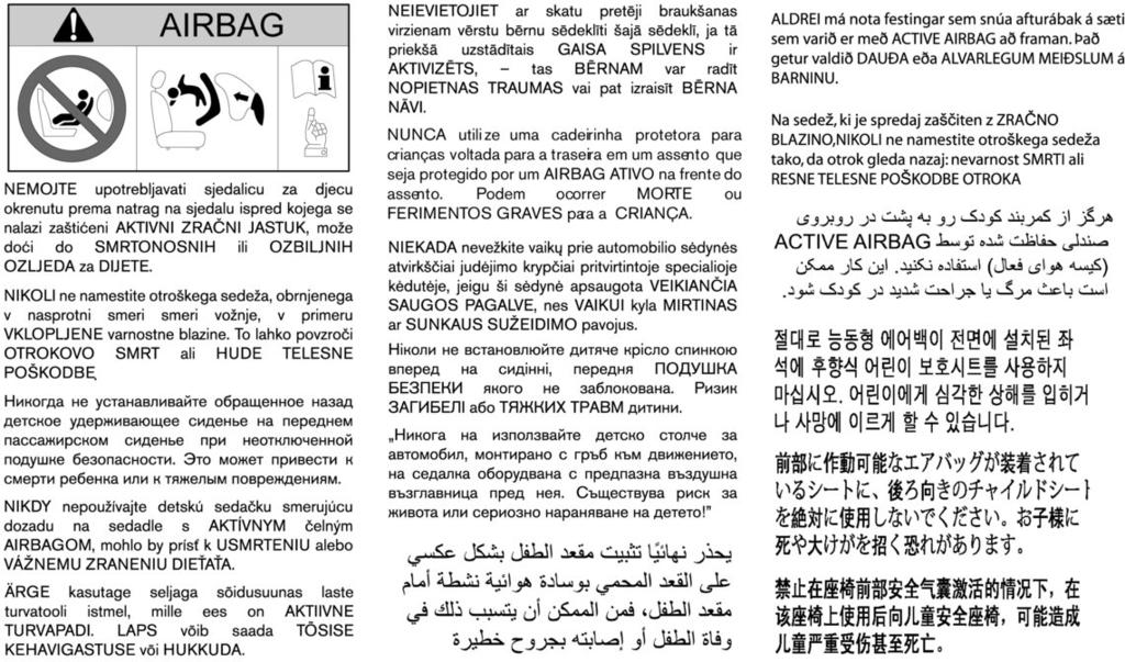
455 m
Foreword MODIFICATION OF YOUR VEHICLE IMPORTANT SAFETY INFORMATION REMINDERS FOR SAFETY! READ FIRST THEN DRIVE SAFELY WHEN READING THE MANUAL
 Foreword Welcome to the growing family of new INFINITI owners. This vehicle has been delivered to you with confidence. It has been produced using the latest techniques and strict quality control. This
For your safety, read carefully and keep in this vehicle. Owner s Manual
 For your safety, read carefully and keep in this vehicle. Q50 Owner s Manual Foreword Welcome to the growing family of new INFINITI owners. This vehicle is delivered to you with confidence. It is produced
BATTERY DISPOSAL. The NISSAN GREEN PROGRAM symbol indicates environmentally friendly information and best practices.
 ECO-MICRA The NISSAN GREEN PROGRAM symbol indicates environmentally friendly information and best practices. This symbol means Do not do this or Do not let this happen. BATTERY DISPOSAL CAUTION An improperly
10/2010 OM10E-0K13E0E
 NOTE Owner's Manual Foreword Welcome to the growing family of new NISSAN owners. This vehicle has been delivered to you with confidence. It has been produced using the latest techniques and strict quality
QASHQAI OWNER'S MANUAL
 QASHQAI OWNER'S MANUAL Foreword Welcome to the growing family of new NISSAN owners. This vehicle has been delivered to you with confidence. It has been produced using the latest techniques and strict quality
WARNING IMPORTANT SAFETY INFORMA- TION REMINDERS FOR SAFETY!
 Foreword Welcome to the growing family of new NISSAN owners. This vehicle is delivered to you with confidence. It was produced using the latest techniques and strict quality control. This manual was prepared
READ FIRST THEN DRIVE SAFELY
 FOREWORD Your INFINITI represents a new way of thinking about vehicle design. It integrates advanced engineering and superior craftsmanship with a simple, refined aesthetic sensitivity associated with
InformationProvidedby:
 Foreword Welcome to the growing family of new NISSAN owners. This vehicle is delivered to you with confidence. It was produced using the latest techniques and strict quality control. This manual was prepared
requirements, assisting you in the safe operation of your vehicle. WARNING IMPORTANT SAFETY INFORMA- TION REMINDERS FOR SAFETY!
 Foreword Welcome to the growing family of new NISSAN owners. This vehicle is delivered to you with confidence. It was produced using the latest techniques and strict quality control. This manual was prepared
For your safety, read carefully and keep in this vehicle Infiniti EX Owner s Manual
 For your safety, read carefully and keep in this vehicle. 2011 Infiniti EX Owner s Manual FOREWORD Your INFINITI represents a new way of thinking about vehicle design. It integrates advanced engineering
2014 cube OWNER S MANUAL. InformationProvidedby: For your safety, read carefully and keep in this vehicle.
 2014 cube OWNER S MANUAL For your safety, read carefully and keep in this vehicle. WHEN READING THE MANUAL This manual includes information for all options available on this model. Therefore, you may
WARNING IMPORTANT SAFETY INFORMATION REMINDERS FOR SAFETY!
 Foreword Your INFINITI represents a new way of thinking about vehicle design. It integrates advanced engineering and superior craftsmanship with a simple, refined aesthetic sensitivity associated with
2016 MICRA OWNER S MANUAL. For your safety, read carefully and keep in this vehicle.
 2016 MICRA OWNER S MANUAL For your safety, read carefully and keep in this vehicle. FOREWORD READ FIRST THEN DRIVE SAFELY Welcome to the growing family of new NISSAN owners. This vehicle is delivered to
WARNING IMPORTANT SAFETY INFORMA- TION REMINDERS FOR SAFETY!
 Foreword Welcome to the growing family of new NISSAN owners. This vehicle is delivered to you with confidence. It was produced using the latest techniques and strict quality control. This manual was prepared
For your safety, read carefully and keep in this vehicle Infiniti G37 Convertible Owner s Manual
 For your safety, read carefully and keep in this vehicle. 2010 Infiniti G37 Convertible Owner s Manual FOREWORD Your INFINITI represents a new way of thinking about vehicle design. It integrates advanced
For your safety, read carefully and keep in this vehicle Infiniti G Convertible Owner s Manual
 For your safety, read carefully and keep in this vehicle. 2011 Infiniti G Convertible Owner s Manual FOREWORD Your INFINITI represents a new way of thinking about vehicle design. It integrates advanced
READ FIRST THEN DRIVE SAFELY
 FOREWORD READ FIRST THEN DRIVE SAFELY Welcome to the growing family of new NISSAN owners. This vehicle is delivered to you with confidence. It was produced using the latest techniques and strict quality
WARNING IMPORTANT SAFETY INFORMA- TION REMINDERS FOR SAFETY!
 Foreword Welcome to the growing family of new NISSAN owners. This vehicle is delivered to you with confidence. It was produced using the latest techniques and strict quality control. This manual was prepared
2015 MICRA OWNER S MANUAL. For your safety, read carefully and keep in this vehicle.
 2015 MICRA OWNER S MANUAL For your safety, read carefully and keep in this vehicle. FOREWORD READ FIRST THEN DRIVE SAFELY Welcome to the growing family of new NISSAN owners. This vehicle is delivered to
WARNING IMPORTANT SAFETY INFORMA- TION REMINDERS FOR SAFETY!
 Foreword Welcome to the growing family of new NISSAN owners. This vehicle is delivered to you with confidence. It was produced using the latest techniques and strict quality control. This manual was prepared
READ FIRST THEN DRIVE SAFELY
 Foreword Your INFINITI represents a new way of thinking about vehicle design. It integrates advanced engineering and superior craftsmanship with a simple, refined aesthetic sensitivity associated with
READ FIRST THEN DRIVE SAFELY
 Foreword Welcome to the growing family of new NISSAN owners. This vehicle is delivered to you with confidence. It was produced using the latest techniques and strict quality control. This manual was prepared
2010 Infiniti M35/M45 Owner's Manual
 2010 Infiniti M35/M45 Owner's Manual FOREWORD Your INFINITI represents a new way of thinking about vehicle design. It integrates advanced engineering and superior craftsmanship with a simple, refined aesthetic
READ FIRST THEN DRIVE SAFELY
 FOREWORD READ FIRST THEN DRIVE SAFELY Welcome to the growing family of new NISSAN owners. This vehicle is delivered to you with confidence. It was produced using the latest techniques and strict quality
2017 MICRA OWNER S MANUAL. For your safety, read carefully and keep in this vehicle.
 2017 MICRA OWNER S MANUAL For your safety, read carefully and keep in this vehicle. FOREWORD READ FIRST THEN DRIVE SAFELY Welcome to the growing family of new NISSAN owners. This vehicle is delivered to
READ FIRST THEN DRIVE SAFELY
 FOREWORD READ FIRST THEN DRIVE SAFELY Welcome to the growing family of new NISSAN owners. This vehicle is delivered to you with confidence. It was produced using the latest techniques and strict quality
READ FIRST THEN DRIVE SAFELY
 FOREWORD READ FIRST THEN DRIVE SAFELY Welcome to the growing family of new NISSAN owners. This vehicle is delivered to you with confidence. It was produced using the latest techniques and strict quality
READ FIRST THEN DRIVE SAFELY
 FOREWORD READ FIRST THEN DRIVE SAFELY Welcome to the growing family of new NISSAN owners. This vehicle is delivered to you with confidence. It was produced using the latest techniques and strict quality
READ FIRST THEN DRIVE SAFELY
 FOREWORD READ FIRST THEN DRIVE SAFELY Welcome to the growing family of new NISSAN owners. This vehicle is delivered to you with confidence. It was produced using the latest techniques and strict quality
READ FIRST THEN DRIVE SAFELY
 FOREWORD READ FIRST THEN DRIVE SAFELY Welcome to the growing family of new NISSAN owners. This vehicle is delivered to you with confidence. It was produced using the latest techniques and strict quality
READ FIRST THEN DRIVE SAFELY
 Foreword Your INFINITI represents a new way of thinking about vehicle design. It integrates advanced engineering and superior craftsmanship with a simple, refined aesthetic sensitivity associated with
READ FIRST THEN DRIVE SAFELY
 FOREWORD READ FIRST THEN DRIVE SAFELY Welcome to the growing family of new NISSAN owners. This vehicle is delivered to you with confidence. It was produced using the latest techniques and strict quality
READ FIRST THEN DRIVE SAFELY
 FOREWORD READ FIRST THEN DRIVE SAFELY Welcome to the growing family of new NISSAN owners. This vehicle is delivered to you with confidence. It was produced using the latest techniques and strict quality
InformationProvidedby:
 Foreword Welcome to the growing family of new NISSAN owners. This vehicle is delivered to you with confidence. It was produced using the latest techniques and strict quality control. This manual was prepared
For your safety, read carefully and keep in this vehicle Infiniti QX50 Owner s Manual
 For your safety, read carefully and keep in this vehicle. 2014 Infiniti QX50 Owner s Manual Foreword Your INFINITI represents a new way of thinking about vehicle design. It integrates advanced engineering
2012 VERSA SEDAN OWNER S MANUAL. For your safety, read carefully and keep in this vehicle.
 2012 VERSA SEDAN OWNER S MANUAL For your safety, read carefully and keep in this vehicle. FOREWORD READ FIRST THEN DRIVE SAFELY Welcome to the growing family of new NISSAN owners. This vehicle is delivered
WARNING IMPORTANT SAFETY INFORMA- TION REMINDERS FOR SAFETY!
 Foreword Welcome to the growing family of new NISSAN owners. This vehicle is delivered to you with confidence. It was produced using the latest techniques and strict quality control. This manual was prepared
READ FIRST THEN DRIVE SAFELY
 FOREWORD READ FIRST THEN DRIVE SAFELY Welcome to the growing family of new NISSAN owners. This vehicle is delivered to you with confidence. It was produced using the latest techniques and strict quality
Foreword MODIFICATION OF YOUR VEHICLE IMPORTANT SAFETY INFORMATION REMINDERS FOR SAFETY! READ FIRST THEN DRIVE SAFELY WHEN READING THE MANUAL
 Foreword Welcome to the growing family of new NISSAN owners. This vehicle has been delivered to you with confidence. It has been produced using the latest techniques and strict quality control. This manual
READ FIRST THEN DRIVE SAFELY
 FOREWORD READ FIRST THEN DRIVE SAFELY Welcome to the growing family of new NISSAN owners. This vehicle is delivered to you with confidence. It was produced using the latest techniques and strict quality
READ FIRST THEN DRIVE SAFELY
 FOREWORD READ FIRST THEN DRIVE SAFELY Welcome to the growing family of new NISSAN owners. This vehicle is delivered to you with confidence. It was produced using the latest techniques and strict quality
OWNER S MANUAL AND MAINTENANCE INFORMATION. For your safety, read carefully and keep in this vehicle.
 2018.5 OWNER S MANUAL AND MAINTENANCE INFORMATION For your safety, read carefully and keep in this vehicle. Owner s Manual Supplement The information contained within this supplement updates the following
READ FIRST THEN DRIVE SAFELY
 FOREWORD READ FIRST THEN DRIVE SAFELY Welcome to the growing family of new NISSAN owners. This vehicle is delivered to you with confidence. It was produced using the latest techniques and strict quality
READ FIRST THEN DRIVE SAFELY
 FOREWORD READ FIRST THEN DRIVE SAFELY Welcome to the growing family of new NISSAN owners. This vehicle is delivered to you with confidence. It was produced using the latest techniques and strict quality
READ FIRST THEN DRIVE SAFELY
 FOREWORD READ FIRST THEN DRIVE SAFELY Welcome to the growing family of new NISSAN owners. This vehicle is delivered to you with confidence. It was produced using the latest techniques and strict quality
Thank you for choosing a Mazda. We at Mazda design and build vehicles with complete customer satisfaction in mind.
 J54L_8R34_EE_02H.BOOK Page 1 Monday, July 15, 2002 9:03 AM A Word to Mazda Owners Thank you for choosing a Mazda. We at Mazda design and build vehicles with complete customer satisfaction in mind. To help
For your safety, read carefully and keep in this vehicle Infiniti Q60 Convertible Owner s Manual
 For your safety, read carefully and keep in this vehicle. 2014 Infiniti Q60 Convertible Owner s Manual Foreword Your INFINITI represents a new way of thinking about vehicle design. It integrates advanced
2013 VERSA SEDAN OWNER S MANUAL. safety, read carefully and keep in this vehicle.
 2013 VERSA SEDAN OWNER S MANUAL For your safety, read carefully and keep in this vehicle. FOREWORD READ FIRST THEN DRIVE SAFELY Welcome to the growing family of new NISSAN owners. This vehicle is delivered
2010 MAXIMA OWNER S MANUAL. For your safety, read carefully and keep in this vehicle.
 2010 MAXIMA OWNER S MANUAL For your safety, read carefully and keep in this vehicle. FOREWORD READ FIRST THEN DRIVE SAFELY Welcome to the growing family of new NISSAN owners. This vehicle is delivered
READ FIRST THEN DRIVE SAFELY
 FOREWORD READ FIRST THEN DRIVE SAFELY Welcome to the growing family of new NISSAN owners. This vehicle is delivered to you with confidence. It was produced using the latest techniques and strict quality
READ FIRST THEN DRIVE SAFELY
 Foreword Your INFINITI represents a new way of thinking about vehicle design. It integrates advanced engineering and superior craftsmanship with a simple, refined aesthetic sensitivity associated with
requirements, assisting you in the safe operation of your vehicle. WARNING IMPORTANT SAFETY INFORMA- TION REMINDERS FOR SAFETY!
 Foreword Welcome to the growing family of new NISSAN owners. This vehicle is delivered to you with confidence. It was produced using the latest techniques and strict quality control. This manual was prepared
FOREWORD WARNING. of your vehicle.
 FOREWORD Your INFINITI represents a new way of thinking about vehicle design. It integrates advanced engineering and superior craftsmanship with a simple, refined aesthetic sensitivity associated with
2011 MAXIMA OWNER S MANUAL. For your safety, read carefully and keep in this vehicle. InformationProvidedby:
 2011 MAXIMA OWNER S MANUAL For your safety, read carefully and keep in this vehicle. FOREWORD READ FIRST THEN DRIVE SAFELY Welcome to the growing family of new NISSAN owners. This vehicle is delivered
2010 TITAN OWNER'S MANUAL. For your safety, read carefully and keep in this vehicle.
 2010 TITAN OWNER'S MANUAL For your safety, read carefully and keep in this vehicle. FOREWORD READ FIRST THEN DRIVE SAFELY Welcome to the growing family of new NISSAN owners. This vehicle is delivered to
requirements, assisting you in the safe operation of your vehicle. WARNING IMPORTANT SAFETY INFORMA- TION REMINDERS FOR SAFETY!
 Foreword Welcome to the growing family of new NISSAN owners. This vehicle is delivered to you with confidence. It was produced using the latest techniques and strict quality control. This manual was prepared
READ FIRST THEN DRIVE SAFELY
 FOREWORD READ FIRST THEN DRIVE SAFELY Welcome to the growing family of new NISSAN owners. This vehicle is delivered to you with confidence. It was produced using the latest techniques and strict quality
2016 MAXIMA OWNER S MANUAL. For your safety, read carefully and keep in this vehicle.
 2016 MAXIMA OWNER S MANUAL For your safety, read carefully and keep in this vehicle. FOREWORD READ FIRST THEN DRIVE SAFELY Welcome to the growing family of new NISSAN owners. This vehicle is delivered
WARNING IMPORTANT SAFETY INFORMA- TION REMINDERS FOR SAFETY!
 Foreword Welcome to the growing family of new NISSAN owners. This vehicle is delivered to you with confidence. It was produced using the latest techniques and strict quality control. This manual was prepared
READ FIRST THEN DRIVE SAFELY
 FOREWORD READ FIRST THEN DRIVE SAFELY Welcome to the growing family of new NISSAN owners. This vehicle is delivered to you with confidence. It was produced using the latest techniques and strict quality
2018 KICKS. OWNER S MANUAL and MAINTENANCE INFORMATION. For your safety, read carefully and keep in this vehicle.
 2018 KICKS OWNER S MANUAL and MAINTENANCE INFORMATION For your safety, read carefully and keep in this vehicle. CALIFORNIA PROPOSITION 65 WARNING WARNING Operating, servicing and maintaining a passenger
2013 NV200 COMPACT CARGO
 2013 NV200 COMPACT CARGO OWNER S MANUAL For your safety, read carefully and keep in this vehicle. FOREWORD READ FIRST THEN DRIVE SAFELY Welcome to the growing family of new NISSAN owners. This vehicle
Owner s Manual Supplement
 Owner s Manual Supplement The information contained within this supplement revises the TIRE CHAINS information in the Maintenance and do-it-yourself section of the 2011-2013 Nissan Quest Owner s Manual.
Z OWNER S MANUAL. InformationProvidedby: For your safety, read carefully and keep in this vehicle.
 2016 370Z OWNER S MANUAL For your safety, read carefully and keep in this vehicle. Foreword Welcome to the growing family of new NISSAN owners. This vehicle is delivered to you with confidence. It was
2010 PATHFINDER OWNER S MANUAL. For your safety, read carefully and keep in this vehicle.
 2010 PATHFINDER OWNER S MANUAL For your safety, read carefully and keep in this vehicle. FOREWORD READ FIRST THEN DRIVE SAFELY Welcome to the growing family of new NISSAN owners. This vehicle is delivered
WARNING IMPORTANT SAFETY INFORMA- TION REMINDERS FOR SAFETY!
 Foreword Welcome to the growing family of new NISSAN owners. This vehicle is delivered to you with confidence. It was produced using the latest techniques and strict quality control. This manual was prepared
READ FIRST THEN DRIVE SAFELY
 Foreword GUID-E7E6B9D7-70D5-46FD-8070-D86AD68B3005 Welcome to the growing family of new NISSAN owners. This vehicle is delivered to you with confidence. It was produced using the latest techniques and
2014 SENTRA OWNER S MANUAL. For your safety, read carefully and keep in this vehicle.
 2014 SENTRA OWNER S MANUAL For your safety, read carefully and keep in this vehicle. FOREWORD READ FIRST THEN DRIVE SAFELY Welcome to the growing family of new NISSAN owners. This vehicle is delivered
2017 VERSA SEDAN. OWNER S MANUAL and MAINTENANCE INFORMATION. For your safety, read carefully and keep in this vehicle.
 2017 VERSA SEDAN OWNER S MANUAL and MAINTENANCE INFORMATION For your safety, read carefully and keep in this vehicle. FOREWORD READ FIRST THEN DRIVE SAFELY Welcome to the growing family of new NISSAN owners.
2015 VERSA SEDAN OWNER S MANUAL. For your safety, read carefully and keep in this vehicle.
 2015 VERSA SEDAN OWNER S MANUAL For your safety, read carefully and keep in this vehicle. FOREWORD READ FIRST THEN DRIVE SAFELY Welcome to the growing family of new NISSAN owners. This vehicle is delivered
READ FIRST THEN DRIVE SAFELY
 FOREWORD READ FIRST THEN DRIVE SAFELY Welcome to the growing family of new INFINITI owners. This vehicle is delivered to you with confidence. It was produced using the latest techniques and strict quality
2012 NV1500/NV2500 HD/NV3500 HD
 2012 NV1500/NV2500 HD/NV3500 HD OWNER S MANUAL For your safety, read carefully and keep in this vehicle. FOREWORD READ FIRST THEN DRIVE SAFELY Welcome to the growing family of new NISSAN owners. This vehicle
READ FIRST THEN DRIVE SAFELY
 Foreword Your INFINITI represents a new way of thinking about vehicle design. It integrates advanced engineering and superior craftsmanship with a simple, refined aesthetic sensitivity associated with
2011 VERSA OWNER S MANUAL. For your safety, read carefully and keep in this vehicle.
 2011 VERSA OWNER S MANUAL For your safety, read carefully and keep in this vehicle. FOREWORD READ FIRST THEN DRIVE SAFELY Welcome to the growing family of new NISSAN owners. This vehicle is delivered to
2012 XTERRA OWNER S MANUAL. For your safety, read carefully and keep in this vehicle. InformationProvidedby:
 2012 XTERRA OWNER S MANUAL For your safety, read carefully and keep in this vehicle. FOREWORD READ FIRST THEN DRIVE SAFELY Welcome to the growing family of new NISSAN owners. This vehicle is delivered
2010 XTERRA OWNER S MANUAL. For your safety, read carefully and keep in this vehicle. InformationProvidedby:
 2010 XTERRA OWNER S MANUAL For your safety, read carefully and keep in this vehicle. FOREWORD READ FIRST THEN DRIVE SAFELY Welcome to the growing family of new NISSAN owners. This vehicle is delivered
2011 XTERRA OWNER S MANUAL. For your safety, read carefully and keep in this vehicle.
 2011 XTERRA OWNER S MANUAL For your safety, read carefully and keep in this vehicle. FOREWORD READ FIRST THEN DRIVE SAFELY Welcome to the growing family of new NISSAN owners. This vehicle is delivered
READ FIRST THEN DRIVE SAFELY
 FOREWORD READ FIRST THEN DRIVE SAFELY Welcome to the growing family of new NISSAN owners. This vehicle is delivered to you with confidence. It was produced using the latest techniques and strict quality
2018 VERSA SEDAN. OWNER S MANUAL and MAINTENANCE INFORMATION. For your safety, read carefully and keep in this vehicle.
 2018 VERSA SEDAN OWNER S MANUAL and MAINTENANCE INFORMATION For your safety, read carefully and keep in this vehicle. FOREWORD READ FIRST THEN DRIVE SAFELY Welcome to the growing family of new NISSAN owners.
READ FIRST THEN DRIVE SAFELY
 Foreword Your INFINITI represents a new way of thinking about vehicle design. It integrates advanced engineering and superior craftsmanship with a simple, refined aesthetic sensitivity associated with
READ FIRST THEN DRIVE SAFELY
 Foreword Your INFINITI represents a new way of thinking about vehicle design. It integrates advanced engineering and superior craftsmanship with a simple, refined aesthetic sensitivity associated with
2011 PATHFINDER OWNER S MANUAL. For your safety, read carefully and keep in this vehicle.
 2011 PATHFINDER OWNER S MANUAL For your safety, read carefully and keep in this vehicle. FOREWORD READ FIRST THEN DRIVE SAFELY Welcome to the growing family of new NISSAN owners. This vehicle is delivered
READ FIRST THEN DRIVE SAFELY
 FOREWORD READ FIRST THEN DRIVE SAFELY Welcome to the growing family of new NISSAN owners. This vehicle is delivered to you with confidence. It was produced using the latest techniques and strict quality
2017 VERSA NOTE. OWNER S MANUAL and MAINTENANCE INFORMATION. For your safety, read carefully and keep in this vehicle.
 2017 VERSA NOTE OWNER S MANUAL and MAINTENANCE INFORMATION For your safety, read carefully and keep in this vehicle. FOREWORD READ FIRST THEN DRIVE SAFELY Welcome to the growing family of new NISSAN owners.
READ FIRST THEN DRIVE SAFELY
 FOREWORD READ FIRST THEN DRIVE SAFELY Welcome to the growing family of new NISSAN owners. This vehicle is delivered to you with confidence. It was produced using the latest techniques and strict quality
READ FIRST THEN DRIVE SAFELY
 FOREWORD READ FIRST THEN DRIVE SAFELY Welcome to the growing family of new NISSAN owners. This vehicle is delivered to you with confidence. It was produced using the latest techniques and strict quality
2012 ALTIMA OWNER S MANUAL. For your safety, read carefully and keep in this vehicle.
 2012 ALTIMA OWNER S MANUAL For your safety, read carefully and keep in this vehicle. FOREWORD READ FIRST THEN DRIVE SAFELY Welcome to the growing family of new NISSAN owners. This vehicle is delivered
READ FIRST THEN DRIVE SAFELY
 FOREWORD READ FIRST THEN DRIVE SAFELY Welcome to the growing family of new NISSAN owners. This vehicle is delivered to you with confidence. It was produced using the latest techniques and strict quality
Black plate (27,1) Index 14 北米Model "A3180BE-B" EDITED: 2014/ 2/ 7
 Index 14 北米Model A3180BE-B EDITED: 2014/ 2/ 7") Index 14 14-2 Index A Abbreviation... 3 ABS (Anti-lock Brake System)... 7-20 Warning light... 3-15, 7-21 Accessories... 5-2, 11-36 Accessory power outlet... 6-10 Active head restraint... 1-6 Air cleaner
Index 14 14-2 Index A Abbreviation... 3 ABS (Anti-lock Brake System)... 7-20 Warning light... 3-15, 7-21 Accessories... 5-2, 11-36 Accessory power outlet... 6-10 Active head restraint... 1-6 Air cleaner
2018 MAXIMA. OWNER S MANUAL and MAINTENANCE INFORMATION. For your safety, read carefully and keep in this vehicle.
 2018 MAXIMA OWNER S MANUAL and MAINTENANCE INFORMATION For your safety, read carefully and keep in this vehicle. FOREWORD READ FIRST THEN DRIVE SAFELY This manual was prepared to help you understand the
2011 ARMADA OWNER S MANUAL. For your safety, read carefully and keep in this vehicle. InformationProvidedby:
 2011 ARMADA OWNER S MANUAL For your safety, read carefully and keep in this vehicle. FOREWORD READ FIRST THEN DRIVE SAFELY Welcome to the growing family of new NISSAN owners. This vehicle is delivered
2013 TITAN OWNER S MANUAL. For your safety, read carefully and keep in this vehicle.
 2013 TITAN OWNER S MANUAL For your safety, read carefully and keep in this vehicle. FOREWORD READ FIRST THEN DRIVE SAFELY Welcome to the growing family of new NISSAN owners. This vehicle is delivered to
2013 XTERRA OWNER S MANUAL. For your safety, read carefully and keep in this vehicle.
 2013 XTERRA OWNER S MANUAL For your safety, read carefully and keep in this vehicle. FOREWORD READ FIRST THEN DRIVE SAFELY Welcome to the growing family of new NISSAN owners. This vehicle is delivered
2018 VERSA NOTE. OWNER S MANUAL and MAINTENANCE INFORMATION. For your safety, read carefully and keep in this vehicle.
 2018 VERSA NOTE OWNER S MANUAL and MAINTENANCE INFORMATION For your safety, read carefully and keep in this vehicle. FOREWORD READ FIRST THEN DRIVE SAFELY This manual was prepared to help you understand
2016 MURANO OWNER S MANUAL. For your safety, read carefully and keep in this vehicle.
 2016 MURANO OWNER S MANUAL For your safety, read carefully and keep in this vehicle. FOREWORD READ FIRST THEN DRIVE SAFELY Welcome to the growing family of new NISSAN owners. This vehicle is delivered
SECTION 1 6 INSTRUMENTS AND CONTROLS. Comfort adjustment. Front seat... 42
 SECTION 1 6 INSTRUMENTS AND CONTROLS Comfort adjustment Front seat................................................ 42 Headrests............................................... 44 Tilt and telescopic steering
2017 ALTIMA SEDAN. OWNER S MANUAL and MAINTENANCE INFORMATION. For your safety, read carefully and keep in this vehicle.
 2017 ALTIMA SEDAN OWNER S MANUAL and MAINTENANCE INFORMATION For your safety, read carefully and keep in this vehicle. FOREWORD READ FIRST THEN DRIVE SAFELY Welcome to the growing family of new NISSAN
Airbags SAFETY INFORMATION. Your vehicle is equipped with several types of airbags: front airbags, side airbags, and side curtain airbags.
 Airbags Your vehicle is equipped with several types of airbags: front airbags, side airbags, and side curtain airbags. Front Airbags (SRS) The front SRS airbags inflate in a moderate-to-severe frontal