For your safety, read carefully and keep in this vehicle. Owner s Manual
|
|
|
- Richard Page
- 6 years ago
- Views:
Transcription
1 For your safety, read carefully and keep in this vehicle. Q50 Owner s Manual
2 Foreword Welcome to the growing family of new INFINITI owners. This vehicle is delivered to you with confidence. It is produced using the latest techniques and strict quality control. This manual was prepared to help you understand the operation and maintenance of your vehicle so that you may enjoy many kilometres (miles) of driving pleasure. Please read through this manual before operating your vehicle. A separate Warranty Information & Maintenance Booklet explains in detail the warranty coverage that applies to your vehicle. Your INFINITI Centre knows your vehicle best. When you require any service or have any questions, your INFINITI Centre will be glad to assist you with the extensive resources available for you. IMPORTANT SAFETY INFORMATION REMINDERS! Follow these important driving rules to help ensure a safe and complete trip for you and your passengers! NEVER drive under the influence of alcohol or drugs. ALWAYS observe posted speed limits and never drive too fast for conditions. ALWAYS use your seat belts and appropriate child restraint systems. Preteen children should be seated in the rear seat. ALWAYS provide information about the proper use of vehicle safety features to all occupants of the vehicle. ALWAYS review this Owner s Manual for important safety information. WHEN READING THE MANUAL This manual includes information for all options available on this model. Therefore, you may find some information that does not apply to your vehicle. Throughout this manual, some illustrations may only show the layout for Left-Hand Drive (LHD) models. For Right-Hand Drive (RHD) models, the illustrated shape and location of some components may differ. All information, specifications and illustrations in this manual are those in effect at the time of printing. INFINITI reserves the right to change specifications or designs at any time without notice and without obligation. MODIFICATION OF YOUR VEHICLE This vehicle should not be modified. Modifications could affect its performance, safety or durability, and may even violate governmental regulations. In addition, damage or performance problems resulting from modifications may not be covered under INFINITI warranties. READ FIRST THEN DRIVE SAFELY Before driving your vehicle, read this Owner s Manual carefully. This will ensure familiarity with controls and maintenance requirements, assisting you in the safe operation of your vehicle. Throughout this manual the following symbols and words are used: WARNING Indicates the presence of a hazard that could cause death or serious personal injury. To avoid or reduce the risk, the procedures described must be followed precisely. CAUTION Indicates the presence of a hazard that could cause minor or moderate personal injury, or damage to your vehicle. To avoid or reduce the risk, the procedures described must be followed carefully. NOTE Indicates additional helpful information.


3 Air bag warning labels: This symbol means Do not do this or Do not let this happen. Arrows in an illustration that are similar to these point to the front of the vehicle. Arrows in an illustration that are similar to these indicate movement or action. NEVER use a rearward facing child restraint on a seat protected by an ACTIVE AIRBAG in front of it, DEATH or SERIOUS INJURY to the CHILD can occur. Be sure to read the Airbag warning labels description in the Safety section of this manual; and the Airbag label description at the end of this manual. Arrows in an illustration that are similar to these call attention to an item in the illustration. [ ]: Square brackets are used to indicate messages, keys, or items displayed on a screen. < >: Chevrons or angle brackets are used to indicate texts on controls like buttons or switches inside or on the vehicle. BATTERY DISPOSAL CAUTION An improperly disposed battery can harm the environment. Always confirm local regulations for battery disposal. Examples of the batteries that the vehicle contains: Vehicle battery Remote controller battery (for Intelligent Key and/or Remote keyless entry system)
4 Tyre Pressure Monitoring System (TPMS) sensor battery Remote controller battery (for Mobile Entertainment system) If in doubt, contact your local authority, or an INFINITI Centre, or a qualified workshop for advice on disposal. INFINITI Genuine Parts and Accessories might be branded either INFINITI or NISSAN
5 Contents Illustrated table of contents 0 Safety seats, seat belts and supplemental restraint system 1 Instruments and controls 2 Pre-driving checks and adjustments 3 Display screen, heater and air conditioner, and audio system 4 Starting and driving 5 In case of emergency 6 Appearance and care 7 Maintenance and do-it-yourself 8 Technical information 9 Index 10
6
7 0 Illustrated table of contents Seats, seat belts and Supplemental Restraint System (SRS) Exterior front Exterior rear Passenger compartment Cockpit Left-Hand Drive (LHD) model Right-Hand Drive (RHD) model Instrument panel Left-Hand Drive (LHD) model Right-Hand Drive (RHD) model Meters and gauges Engine compartment VR30DDTT engine model L Turbo engine model L Diesel engine model
8 SEATS, SEAT BELTS AND SUPPLEMENTAL RESTRAINT SYSTEM (SRS) 11. Front passenger air bag status light (P. 1-39) 12. Front passenger air bag switch (P. 1-40) NIC Child restraint anchorage (P. 1-26) 2. Head restraints (P. 1-8) 3. Seat belts (P. 1-11) 4. Pre-tensioner seat belt system (P. 1-40) 5. Supplemental curtain side-impact air bags (P. 1-32) 6. Front seats (P. 1-2) 7. Supplemental front-impact air bags (P. 1-32) 8. ISOFIX child restraint system (P. 1-24) 9. Rear seats (P. 1-6) Child restraints (P. 1-19) 10. Supplemental side-impact air bags (P. 1-32) 0-2 Illustrated table of contents
9 EXTERIOR FRONT 1. Bonnet (P. 3-19) 2. Windscreen wipers and washers Switch operation (P. 2-35) Blade replacement (P. 8-19) Window washer fluid (P. 8-20) Windscreen de-icer* (P. 2-38) 3. Headlights Switch operation (P. 2-29) Adaptive Front lighting System (AFS)* (P. 2-32) Maintenance (P. 8-27) 4. Sunroof* (P. 2-42) 5. Power windows (P. 2-39) JVC0620X 6. Outside rearview mirrors (P. 3-24) Side turn signal light (P. 2-33) Side view camera* (See the Infiniti InTouch Owner s Manual) 7. Recovery hook (P. 6-22) 8. Parking sensor (sonar) system* (See the Infiniti InTouch Owner s Manual) 9. Front camera* (See the Infiniti InTouch Owner s Manual) 10. Front turn signal lights (P. 2-33) 11. Front fog lights* (P. 2-34) 12. Headlight cleaner* (P. 2-32) 13. Tyres Tyre Pressure Monitoring System (TPMS) (P. 2-7, P. 5-5) Tyres and wheels (P. 8-33) Flat tyre (P. 6-2) Specifications (P. 9-9) 14. Doors Keys (P. 3-2) Door locks (P. 3-3) Intelligent Key system (P. 3-6) Security system (P. 3-17) Courtesy light* (P. 2-48) *: where fitted Illustrated table of contents 0-3
10 EXTERIOR REAR 8. Rear combination light (P. 8-27) 9. Fuel-filler lid Operation (P. 3-22) Fuel information (P. 9-6) 10. Child safety rear door locks (P. 3-5) *: where fitted JVC0621X 1. Boot Boot lid (P. 3-21) Battery (for 2.2L diesel engine and 2.0L turbo petrol engine models) (P. 8-21) AdBlue tank* (P. 5-3, P. 8-12) 2. High-mounted stop light (P. 8-27) 3. DAB radio antenna* (P. 4-3) 4. Rear window defogger (P. 2-37)/Antenna (P. 4-3) 5. Parking sensor (sonar) system* (See the Infiniti InTouch Owner s Manual) 6. Rear view camera (See the Infiniti InTouch Owner s Manual) 7. Recovery hook (P. 6-22) 0-4 Illustrated table of contents
11 PASSENGER COMPARTMENT 10. Rear armrest/boot pass-through (P. 1-7) 11. Rear cup holders (P. 2-46) 12. Rear ashtray* (P. 2-45) 13. Console box (P. 2-45) Power outlet (P. 2-43) Media hub (See the Infiniti InTouch Owner s Manual) 14. Front cup holders (P. 2-46) 15. Front passenger air bag status light (P. 2-12) *: where fitted JVC0425X 1. Coat hooks (P. 2-47) 2. Rear personal light (P. 2-49) 3. Sun visors (P. 3-48) 4. Map light (P. 2-49) 5. Sunroof switch* (P. 2-42) 6. Sunglasses holder (P. 2-46) 7. Door armrest Power windows controls (P. 2-39) Power door lock switch (P. 3-4) Outside rearview mirror remote control switch (P. 3-25) 8. Automatic drive positioner switch* (P. 3-28) 9. Inside rearview mirror (P. 3-24) Illustrated table of contents 0-5
12 COCKPIT LEFT-HAND DRIVE (LHD) MODEL 1. Side vent (P. 4-2) 2. Headlight, turn signal, and fog light switch Headlight (P. 2-29) Turn signal (P. 2-33) Fog light (P. 2-34) 3. Steering wheel Power steering system (P ) Horn (P. 2-39) Driver s supplemental front-impact air bag (P. 2-32) Heated steering wheel* (P. 2-38) 4. Windscreen wiper and washer switch (P. 2-35) JVC0622X 5. Hazard indicator flasher switch (P. 6-2) 6. Shift lever Automatic Transmission (AT) (P. 5-14) Manual Transmission (MT) (P. 5-19) 7. INFINITI controller (See the Infiniti InTouch Owner s Manual) 8. Vehicle Dynamic Control (VDC) OFF switch (except for Europe) (P. 5-27) or Electronic Stability Programme (ESP) OFF switch (P. 5-29) 9. Stop/Start OFF switch* or Idling Stop OFF switch* (P. 5-36) 10. Boot lid release switch (P. 3-21) 11. Instrument brightness control switch (P. 2-3) 12. TRIP/RESET switch for twin trip odometer (P. 2-2) 13. Electric tilting/telescopic steering wheel switch* (P. 3-24) 14. Manual tilting/telescopic steering wheel lever* (P. 3-23) 15. Steering-wheel-mounted controls (left side) Audio control steering switch (See the Infiniti InTouch Owner s Manual) Hands-free phone system switch (See the Infiniti InTouch Owner s Manual) Voice recognition system switch (See the Infiniti InTouch Owner s Manual) 0-6 Illustrated table of contents
13 16. Steering-wheel-mounted controls (right side) Trip computer switch (P. 2-25) Speed limiter switches (P. 5-60) Cruise control switches* (P. 5-62) Intelligent Cruise Control (ICC) system switches* (P. 5-64, P. 5-79) Dynamic driver assistance switch* (P. 5-40, P. 5-45, P. 5-95) 17. INFINITI Drive Mode Selector (P. 5-22) *: where fitted Illustrated table of contents 0-7
14 RIGHT-HAND DRIVE (RHD) MODEL 1. INFINITI controller (See the Infiniti InTouch Owner s Manual) 2. Shift lever Automatic Transmission (AT) (P. 5-14) Manual Transmission (MT) (P. 5-19) 3. Hazard indicator flasher switch (P. 6-2) 4. Headlight, turn signal, and fog light switch Headlight (P. 2-29) Turn signal (P. 2-33) Fog light (P. 2-34) 5. Steering wheel Power steering system (P ) Horn (P. 2-39) JVC0623X Driver s supplemental front-impact air bag (P. 1-32) Heated steering wheel* (P. 2-38) 6. Windscreen wiper and washer switch (P. 2-35) 7. Side vent (P. 4-2) 8. INFINITI Drive Mode Selector (P. 5-22) 9. Steering-wheel-mounted controls (left side) Audio control steering switch (See the Infiniti InTouch Owner s Manual) Hands-free phone system switch (See the Infiniti InTouch Owner s Manual) Voice recognition system switch (See the Infiniti InTouch Owner s Manual) 10. Electric tilting/telescopic steering wheel switch* (P. 3-24) 11. Steering-wheel-mounted controls (right side) Trip computer switch (P. 2-25) Speed limiter switches (P. 5-60) Cruise control switches* (P. 5-62) Intelligent Cruise Control (ICC) system switches* (P. 5-64, P. 5-79) Dynamic driver assistance switch* (P. 5-40, P. 5-45, P. 5-95) 12. Manual tilting/telescopic steering wheel lever* (P. 3-23) 0-8 Illustrated table of contents
15 13. Instrument brightness control switch (P. 2-3) 14. TRIP/RESET switch for twin trip odometer (P. 2-2) 15. Boot lid release switch (P. 3-21) 16. Stop/Start OFF switch (P. 5-36) 17. Electronic Stability Programme (ESP) OFF switch (P. 5-29) *: where fitted Illustrated table of contents 0-9
16 INSTRUMENT PANEL LEFT-HAND DRIVE (LHD) MODEL 1. Paddle shifter* (P. 5-16) 2. Meters and gauges (P. 2-2) Clock (P. 2-28) 3. Push-button ignition switch (P. 5-10) 4. Centre vent (P. 2-2) JVC0624X 5. Heater and air conditioner (See the Infiniti InTouch Owner s Manual) 6. Upper touch screen display (upper display) and Navigation system* (See the Infiniti InTouch Owner s Manual) 7. Lower touch screen display (lower display) (See the Infiniti InTouch Owner s Manual) 8. Defogger switch (P. 2-37)/Windscreen de-icer switch* (P. 2-38) 9. Front passenger s supplemental frontimpact air bag (P. 2-32) 10. Bonnet release handle (P. 3-19) 11. Fuse box cover (P. 8-24) 12. Parking brake pedal (Automatic Transmission (AT) model) Operation (P. 3-27) Parking (P ) Maintenance (P. 8-15) 13. Parking brake lever (Manual Transmission (MT) model) Operation (P. 3-28) Parking (P ) Maintenance (P. 8-15) 14. Ashtray and cigarette lighter* (P. 2-44) or Storage box* (P. 2-45)/ power outlet* (P. 2-43) 15. Heated seat switches* (P. 1-5) 16. Audio system (See the Infiniti InTouch Owner s Manual) 17. Glove box lid release handle (P. 2-45) *: where fitted 0-10 Illustrated table of contents
17 JVC0625X 8. Meters and gauges (P. 2-2) 9. Paddle shifter* (P. 5-16) 10. Glove box lid release handle (P. 2-45) 11. Parking brake lever (Manual Transmission (MT) model) Operation (P. 3-28) Parking (P ) 12. Storage box (P. 2-45)/power outlet* (2-43) 13. Heated seat switches* (P. 1-5) 14. Audio system (See the Infiniti InTouch Owner s Manual) 15. Parking brake pedal (Automatic Transmission (AT) model) Operation (P. 3-27) Parking (P ) 16. Fuse box cover (P. 8-24) 17. Bonnet release handle (P. 3-19) *: where fitted RIGHT-HAND DRIVE (RHD) MODEL 1. Front passenger s supplemental frontimpact air bag (P. 2-32) 2. Heater and air conditioner (See the Infiniti InTouch Owner s Manual) 3. Defogger switch (P. 2-37) 4. Lower touch screen display (lower display) (See the Infiniti InTouch Owner s Manual) 5. Upper touch screen display (upper display) and Navigation system* (See the Infiniti InTouch Owner s Manual) 6. Centre vent (P. 2-2) 7. Push-button ignition switch (P. 5-10) Illustrated table of contents 0-11
18 METERS AND GAUGES JVC0502X 1. Tachometer (P. 2-2) 2. Warning and indicator lights (P. 2-5) 3. Speedometer (P. 2-2) 4. Engine coolant temperature gauge (P. 2-2) 5. Vehicle information display (P. 2-16) Odometer/twin trip odometer (P. 2-2) Automatic Transmission (AT) position indicator* (P. 2-23) 6. Fuel gauge (P. 2-3) *: where fitted 0-12 Illustrated table of contents

19 ENGINE COMPARTMENT JVM0704X To remove the engine compartment cover, unhook the clips located as illustrated. Illustrated table of contents 0-13
20 *1: The layout illustrated is for the Left-Hand Drive (LHD) model. On the Right-Hand Drive (RHD) model, these components are located on the opposite side. *2: For the Right-Hand Drive (RHD) model, another fuse holder is located near the battery. JVC0968X VR30DDTT ENGINE MODEL 1. Battery *1 (P. 8-20) 2. Engine oil dipstick (P. 8-9) 3. Engine oil filler cap (P. 8-9) 4. Brake fluid reservoir *1 (P. 8-16) 5. Fuse/fusible link holder*2 (P. 8-24) 6. Air cleaner (P. 8-18) 7. Engine drive belt location (P. 8-14) 8. Radiator filler cap (P. 8-6) 9. Intercooler coolant resevoir (P. 8-8) 10. Engine coolant resevoir (P. 8-6) 11. Window washer fluid resevoir (P. 8-20) 0-14 Illustrated table of contents
 model, these components are located on the opposite side. JVC0646X 2.0L TURBO ENGINE MODEL 1. Fuse and fusible link holder* (P. 8-24) 2. Battery* (P. 8-20) 3.")
21 The auxiliary battery is located in the boot. (See Battery in the 8. Maintenance and do-it-yourself section (P ) *: The layout illustrated is for the Left-Hand Drive (LHD) model. On the Right-Hand Drive (RHD) model, these components are located on the opposite side. JVC0646X 2.0L TURBO ENGINE MODEL 1. Fuse and fusible link holder* (P. 8-24) 2. Battery* (P. 8-20) 3. Engine oil filler cap (P. 8-9) 4. Brake fluid reservoir* (P. 8-16) 5. Engine coolant reservoir (P. 8-6) 6. Fuse and fusible link holder (P. 8-24) 7. Engine oil dipstick (P. 8-9) 8. Engine drive belt location (P. 8-14) 9. Power steering fluid reservoir (where fitted) (P. 8-18) 10. Window washer fluid reservoir (P. 8-20) Illustrated table of contents 0-15
 model, these components are located on the opposite side. JVC0626X 2.2L Diesel ENGINE MODEL 1. Fuse and fusible link holder* (P. 8-24) 2. Battery* (P. 8-20) 3.")
22 10. Window washer fluid reservoir (P. 8-20) The auxiliary battery is located in the boot. (See Battery in the 8. Maintenance and do-it-yourself section (P ) *: The layout illustrated is for the Left-Hand Drive (LHD) model. On the Right-Hand Drive (RHD) model, these components are located on the opposite side. JVC0626X 2.2L Diesel ENGINE MODEL 1. Fuse and fusible link holder* (P. 8-24) 2. Battery* (P. 8-20) 3. Engine oil filler cap (P. 8-9) 4. Brake and clutch (where fitted) fluid reservoir* (P. 8-16) 5. Engine coolant reservoir (P. 8-6) 6. Fuse and fusible link holder (P. 8-24) 7. Engine drive belt location (P. 8-14) 8. Engine oil dipstick (P. 8-9) 9. Power steering fluid reservoir (where fitted) (P. 8-18) 0-16 Illustrated table of contents
23 1 Safety seats, seat belts and supplemental restraint system Seats Front seats Rear seats Armrest Head restraints Adjustable head restraint components Non-adjustable head restraint components Remove Install Adjust Active head restraints (where fitted) Seat belts Precautions on seat belt usage Child safety Pregnant women Injured persons Pre-crash seat belts with comfort function (front seats) (where fitted) Centre mark on seat belts Three-point type seat belt Seat belt maintenance Child restraints Precautions on child restraints usage Universal child restraints for front seat and rear seats ISOFIX child restraint system Child restraint anchorage Child restraint installation using ISOFIX Child restraint installation using three-point type seat belt Supplemental restraint system Precautions on Supplemental Restraint System (SRS) Supplemental air bag systems Pre-tensioner seat belt system Repair and replacement procedure Pop-up engine bonnet (where fitted)

24 SEATS Manual seat adjustment WARNING After adjusting a seat, gently shake the seat to confirm that the seat is locked securely. If the seat is not locked securely, it may move suddenly and could cause the loss of control of the vehicle. SSS0133Z WARNING Do not drive and/or ride in the vehicle with the seatback reclined. This can be dangerous. The shoulder belt will not be properly against the body. In an accident, you and your passengers could be thrown into the shoulder belt and receive neck or other serious injuries. You and your passengers could also slide under the lap belt and receive serious injuries. For the most effective protection while the vehicle is in motion, the seatback should be upright. Always sit well back and upright in the seat and adjust the seat properly. See Seat belts later in this section. Do not leave children unattended inside the vehicle. They could unknowingly activate switches or controls, or move the vehicle. Unattended children could become involved in serious accidents. To help avoid risk of injury or death through unintended operation of the vehicle and/or its systems, do not leave children, people who require the assistance of others, or pets unattended in your vehicle. Additionally, the temperature inside a closed vehicle on a warm day can quickly become high enough to cause a significant risk of injury or death to people and pets. CAUTION When adjusting the seat positions, be sure not to contact any moving parts to avoid possible injuries and/ or damages. FRONT SEATS WARNING Do not adjust the driver s seat while driving so that full attention may be given to vehicle operation. 1-2 Safety seats, seat belts and supplemental restraint system
25 Seat lifter: Forward and backward: 1. Pull the adjustment lever j1 up. 2. Slide the seat to the desired position. 3. Release the adjustment lever to lock the seat in position. Reclining: 1. Pull the adjustment lever j2 up. 2. Tilt the seatback to the desired position. 3. Release the adjustment lever to lock the seatback in position. CAUTION When moving the seats forward or backward, or returning a rear-reclined seatback to its upright position, make sure you hold onto the seatback while operating. If the seatback is not held, the seat or seatback will move suddenly and could cause injury. The reclining feature allows the adjustment of the seatback for occupants of different sizes to help obtain the proper seat belt fit. (See Seat belts later in this section.) The seatbackmay be reclined to allow occupants to rest while the vehicle is parked. WARNING SSS0792Z The seatback should not be reclined any more than needed for comfort. Seat belts are most effective when the passenger sits well back and straight up in the seat. If the seatback is reclined, the risk of sliding under the lap belt and being injured is increased. SSS0793Z Pull the adjustment lever up or push it down as shown to adjust the seat height until the desired position is achieved. Power seat adjustment Operating tips: The power seat motor has an auto-reset overload protection circuit. Ifthe motor stopsduring the seat adjustment, wait 30 seconds, then reactivate the switch. To avoid discharge of the battery, do not operate the power seats for a long period of time when the engine is not running. For the automatic drive positioner (where fitted) operation, see Automatic drive positioner (where fitted) in the 3. Pre-driving checks and adjustments section. Safety seats, seat belts and supplemental restraint system 1-3
26 Seat lifter: SSS1051Z Forward and backward: Move the adjustment switch j1 forward or backward until the desired position is reached. Reclining: Move the adjustment switch j2 forward or backward until the desired position is reached. The reclining feature allows the adjustment of the seatback for occupants of different sizes to help obtain the proper seat belt fit. (See Seat belts later in this section.) The seatbackmay be reclined to allow occupants to rest while the vehicle is parked. WARNING The seatback should not be reclined any more than needed for comfort. Seat belts are most effective when the passenger sits well back and straight up in the seat. If the seatback is reclined, the risk of sliding under the lap belt and being injured is increased. SSS1052Z 1. Pull the adjustment switch up or push it down as shown to adjust the seat height until the desired position is achieved. 2. Tilt the adjustment switch up or down as shown to adjust the front angle of the seat until the desired position is achieved. 1-4 Safety seats, seat belts and supplemental restraint system
: Thigh extension (where fitted) JVR0186XZ SSS1057Z The side support feature allows you to adjust the torso supports.")
 Manual adjustment type: SSS0684Z Move the adjustment lever j1 forward or backward to adjust the seat lumbar area until the desired position is achieved.")

27 Side support (where fitted): The lumbar support feature provides lower back support to the driver. Power adjustment type (where fitted): Thigh extension (where fitted) JVR0186XZ SSS1057Z The side support feature allows you to adjust the torso supports. Push the switch up j1 or down j2 to adjust the torso area. Lumbar support (where fitted) Manual adjustment type: SSS0684Z Move the adjustment lever j1 forward or backward to adjust the seat lumbar area until the desired position is achieved. SSS1053 The lumbar support feature provides lower back support to the driver. Push each side of the adjustment switch as shown to adjust the seat lumbar area until the desired position is achieved. The front portion of the front seats can be extended forward for seating comfort. Pull up and hold the lever j1 to extend the front portion to the desired position. Heated seats (where fitted) WARNING Do not use or allow occupants to use the seat heater if you or the occupants cannot monitor elevated seat temperatures or have an inability to feel pain in those body parts in contact with the seat. Use of the seat heater by such people could result in serious injury. CAUTION The battery could run down if the seat heater is operated while the engine is not running. Do not use the seat heater for extended periods or when no one is using the seat. Safety seats, seat belts and supplemental restraint system 1-5
28 Do not put anything on the seat which insulates heat, such as a blanket, cushion, seat cover, etc. Otherwise, the seat may become overheated. Do not place anything hard or heavy on the seat or pierce it with a pin or similar object. This may result in damage to the heater. Any liquid spilled on the heated seat should be removed immediately with a dry cloth. When cleaning the seat, never use petrol, thinner, or any similar materials. If any malfunctions are found or the heated seat does not operate properly, turn the switch off and have the system checked by an INFINITI Centre or qualified workshop. JVR0505XZ The front seats can be warmed by built-in heaters. The heating system of the driver s seat and front passenger seat can be operated independently. Operation with switch: 1. Start the engine. 2. Push the switch on the instrument panel. Each time the switch is pushed, the seat heating mode will change in the following order. AUTO High Mid Low OFF The indicator light j1 on the switch will illuminate when the heater is on. When the vehicle s interior is warmed be sure to turn the seat heater off. Operation with touch screen: Push the <CLIMATE> button and touch [m ]or [m ] on the lower display. Select an item from [AUTO], [High], [Mid], [Low] or [OFF]. AUTO mode setting: When in the [AUTO] mode, the heater will turn on or off automatically according to conditions such as the temperature inside the vehicle compartment. Depending on the conditions, the heater will not turn on even if [AUTO] is selected. The setting for [AUTO] mode can be changed. For details, see the Infiniti InTouch Owner s Manual. REAR SEATS Folding (where fitted) WARNING Never allow anyone to ride in the cargo area (boot) or on the rear seat when it is in the fold-down position. Use of these areas by passengers without proper restraints could result in serious injury or death in an accident or sudden stop. Properly secure all cargo with ropes or straps to help prevent it from sliding or shifting. Do not place cargo higher than the seatbacks. In a sudden stop or collision, unsecured cargo could cause personal injury. When returning the seatbacks to the upright position, be certain they are completely secured in the latched position. If they are not completely secured, passengers may be injured in an accident or sudden stop. Closely supervise children when they are around cars to prevent them from playing and becoming locked in the boot where they could be seriously injured. Keep the car locked, with the rear seatback and boot lid securely latched when not in use, and prevent children s access to car keys. 1-6 Safety seats, seat belts and supplemental restraint system
29 Alwaysreconnectthe centre seatbeltwhen the seat is returned to the upright position. Remove drink containers from the rear cup holder. To fold the seatback: 1. Open the boot lid. 2. Pull the strap located on the left and right side of the boot. The rear seatback will be unlatched. 3. Fold the rear seatback down. Interior boot access JVR0187XZ JVR0195X The rear seatback can be folded according to the following procedure. Before folding the seatback: Disconnect and stow the centre seat belt and tongue into the retractor base. (See Rear centre seat belt (models with rear seat folding) later in this section.) To return the seatback: 1. Fold up the rear seatback. 2. Securely lock the seatback in position. ARMREST Rear SSS1061Z Pull the armrest forward until it is horizontal as shown. The rear centre seatback can be folded to allow boot access from inside of the vehicle. To access the boot, pull down the rear centre armrest and pull out the interior boot access lid j1. To lock the lid, use the mechanical key and turn it to the lock position j2. To unlock, turn the key to the unlock position j3. For the mechanical key usage, see Keys in the 3. Pre-driving checks and adjustments section. Make sure that the key is removed from the access lid key cylinder before opening or closing the interior boot access lid. Otherwise, the lid and the rear armrest may be damaged. Safety seats, seat belts and supplemental restraint system 1-7
30 HEAD RESTRAINTS WARNING Head restraints supplement the other vehicle safety systems. They may provide additional protection against injury in certain rear end collisions. Adjustable head restraints must be adjusted properly, as specified in this section. Check the adjustment after someone else uses the seat. Do not attach anything to the head restraint stalks or remove the head restraint. Do not use the seat if the head restraint has been removed. If the head restraint was removed, reinstall and properly adjust the head restraint before an occupant uses the seating position. Failure to follow these instructions can reduce the effectiveness of the head restraints. This may increase the risk of serious injury or death in a collision. Your vehicle is equipped with head restraints that may be integrated, adjustable or non-adjustable. Adjustable head restraints have multiple notches along the stalk to lock them in a desired adjustment position. The non-adjustable head restraints have a single locking notch to secure them to the seat frame. Proper Adjustment: For the adjustable type, align the head restraint so the centre of your ear is approximately level with the centre of the head restraint. If your ear position is still higher than the recommended alignment, place the head restraint at the highest position. If the head restraint has been removed, ensure that it is reinstalled and locked in place before riding in that designated seating position. ADJUSTABLE HEAD RESTRAINT COMPONENTS 1. Removable head restraint 2. Multiple notches 3. Lock knob 4. Stalks SSS0992Z NON-ADJUSTABLE HEAD RESTRAINT COMPONENTS 1. Removable head restraint 2. Single notch 3. Lock knob 4. Stalks JVR0203XZ 1-8 Safety seats, seat belts and supplemental restraint system

31 REMOVE INSTALL ADJUST SSS1037Z SSS1038Z SSS0997Z Use the following procedure to remove the head restraint. 1. Pull the head restraint up to the highest position. 2. Push and hold the lock knob. 3. Remove the head restraint from the seat. 4. Store the head restraint properly in a secure place so it is not loose in the vehicle. 5. Reinstall and properly adjust the head restraint before an occupant uses the seating position. 1. Align the head restraint stalks with the holes in the seat. Make sure that the head restraint is facing the correct direction. The stalk with the adjustment notch j1 must be installed in the hole with the lock knob j2. 2. Push and hold the lock knob and push the head restraint down. 3. Properly adjust the head restraint before an occupant uses the seating position. For adjustable head restraint Adjust the head restraint so the centre is level with the centre of your ears. If your ear position is still higher than the recommended alignment, place the head restraint at the highest position. Safety seats, seat belts and supplemental restraint system 1-9
32 Make sure the head restraint is positioned from the stored position or any non-latch position so the lock knob is engaged in the notch before riding in that designated seating position. Lower ACTIVE HEAD RESTRAINTS (where fitted) For non-adjustable head restraint Make sure the head restraint is positioned from the stored position or any non-latch position so the lock knob is engaged in the notch before riding in that designated seating position. Raise To raise the head restraint, pull it up. JVR0259XZ SSS1035Z SSS1036Z To lower, push and hold the lock knob and push the head restraint down. Make sure the head restraint is positioned so the lock knob is engaged in the notch before riding in that designated seating position. SSS0508Z WARNING Failure to adjust the head restraint properly may reduce the effectiveness of the active head restraint. Always adjust the head restraint as described earlier in this section. Do not attach anything to the head restraint stalks. Doing so could impair the active head restraint function. Always wear seat belts. Active head restraints are designed to supplement other safety systems. No system can prevent all injuries in any accident. The active head restraint moves forward utilising the force that the seatback receives from the occupant in a rear-end collision. The movement of the head restraint helps support the front occupant s head by reducing its backward movement and helps absorb some of the forces that may lead to whiplash type injuries Safety seats, seat belts and supplemental restraint system
33 SEAT BELTS Active head restraints are effective to provide protection at low to medium speeds in which whiplash injury seems to occur most. Active head restraints operate only in certain rear-end collisions. After the collision, the head restraints return to their original positions. Properly adjust the active head restraints as described in the previous section. PRECAUTIONS ON SEAT BELT USAGE Ifyou are wearing the seat belt properly adjusted and sitting upright and well back in the seat, chances of being injured or killed in an accident and/or the severity of injury may be greatly reduced. INFINITI strongly encourages you and all of your passengers to buckle up every time you drive, even if your seating position includes the supplemental air bag systems. Safety seats, seat belts and supplemental restraint system 1-11
34 SSS0134AZ SSS0014Z SSS0136AZ SSS0016Z WARNING Seat belts are designed to bear upon the bony structure of the body, and should be worn low across the front of the pelvis or the pelvis, chest and shoulders, as applicable; wearing the lap sec Safety seats, seat belts and supplemental restraint system
35 tion of the belt across the abdominal area must be avoided. Serious injury may occur if a seat belt is not worn properly. Position the lap belt as low and snug as possible around the hips, not the waist. A lap belt worn too high could increase the risk of internal injuries in an accident. Do not allow more than one person to use the same seat belt. Each belt assembly must only be used by one occupant; it is dangerous to put a belt around a child being carried on the occupant s lap. Never carry more people in the vehicle than there are seat belts. Never wear seat belts inside out. Belts should not be worn with straps twisted. Doing so may reduce their effectiveness. Seat belts should be adjusted as firmly as possible, consistent with comfort, to provide the protection for which they have been designed. A slack belt will greatly reduce the protection afforded to the wearer. Every person who drives or rides in this vehicle should use a seat belt at all times. Children should be properly restrained in the rear seats and in an appropriate restraint. Do not put the belt behind your back or under your arm. Always route the shoulder belt over your shoulder and across your chest. The belt should be away from your face and neck, but not falling off your shoulder. Serious injury may occur if a seat belt is not worn properly. No modifications or additions should be made by the user which will either prevent the seat belt adjusting devices from operating to remove slack, or prevent the seat belt assembly from being adjusted to remove slack. Care should be taken to avoid contamination of the webbing with polishes, oilsand chemicals, and particularly battery acid. Cleaning may safely be carried out using mild soap and water. The belt should be replaced if webbing becomes frayed, contaminated or damaged. It is essential to replace the entire assembly after it has been worn in a severe impact even if damage to the assembly is not obvious. All seat belt assemblies including retractors and attaching hardware should be inspected after any collision by an INFINITI Centre or qualified workshop. INFINITI recommends that all seat belt assemblies in use during a collision be replaced unless the collision was minor and the belts show no damage and continue to operate properly. Seat belt assemblies not in use during a collision should also be inspected and, when necessary, replaced if either damage or improper operation is noted. Once the pre-tensioner seat belt has activated, it cannot be reused. It must be replaced together with the retractor. Contact an INFINITI Centre or qualified workshop. Removal and installation of the pre-tensioner seat belt system components should be done by an INFINITI Centre or qualified workshop. CHILD SAFETY WARNING Infants and children need special protection. The vehicle s seat belts may not fit them properly. The shoulder belt may come too close to the face or neck. The lap belt may not fit over their small hipbones. In an accident, an improperly fitted seat belt could cause serious or fatal injury. Always use an appropriate child restraint system. Children need adults to help protect them. They need to be properly restrained. The proper restraint depends on the child s size. Safety seats, seat belts and supplemental restraint system 1-13
36 Infants and small children SSS0099Z INFINITI recommends that infants and small children be seated in a child restraint system. You should choose a child restraint system that fits your vehicle and the child, and always follow the manufacturer s instructions for installation and use. Large children WARNING Never allow children to stand or kneelon anyseats. Never allow children in the luggage areas while the vehicle is moving. A child could be seriously injured or killed in an accident or sudden stop. Children who are too large for a child restraint system should be seated and restrained by the seat belts that are provided. If the child s seating position has a shoulder belt that fits close to the face or neck, the use of a booster seat (commercially available) may help overcome this. The booster seat should raise the child so that the shoulder belt is properly positioned across the top, middle portion of the shoulder and the lap belt is low on the hips. The booster seat should also fit the vehicle seat. Once the child has grown so that the shoulder belt is no longer on or near the face or neck of the child, use the shoulder belt without the booster seat. In addition, there are many types of child restraint systems available for larger children that should be used for maximum protection. PREGNANT WOMEN INFINITI recommends that pregnant women use seat belts. The seat belt should be worn snug, and always position the lap belt as low as possible around the hips, not the waist, and place the shoulder belt over your shoulder and across your chest. Never run the lap/shoulder belt over your abdominal area. Contact your doctor for specific recommendations. INJURED PERSONS INFINITI recommends that injured persons use seat belts, depending on the injury. Check with your doctor for specific recommendations. PRE-CRASH SEAT BELTS WITH COMFORT FUNCTION (front seats) (where fitted) The pre-crash seat belt tightens the seat belt with a motor to help restrain front seat occupants. This helps reduce the risk of injury in a collision. The motor retracts the seat belt under the following emergency conditions: During emergency braking During sudden steering manoeuvres Activation of the Intelligent Brake Assist (IBA) system. (See Forward emergency braking system (where fitted) in the 5. Starting and driving section.) The pre-crash seat belt will not be active when: The seat belt is not fastened. The vehicle speed is under 15 km/h (10 MPH) during emergency braking. The vehicle speed is under 30 km/h (19 MPH) during sudden steering manoeuvres. The pre-crash seat belt will not be active when the brake pedal is not depressed except when sudden steering manoeuvres occur or the forward emergency braking system activates Safety seats, seat belts and supplemental restraint system
37 The motor also retracts the seat belt when the seat belt is fastened or unfastened. When the seat belt is fastened, the motor tightens the seat belt for a snug fit. When the seat belt is unfastened, the motor retracts the seat belt. If the seat belt is not fully retracted, the motor retracts the seat belt when the door is opened. Always wear your seat belt correctly and sit upright and well back. If the motor cannot retract the seat belt when the seat belt is fastened or unfastened, it may indicate the pre-crash seat belt system has a malfunction. Have your INFINITI Centre or qualified workshop check and repair the system. When the seat belt is retracted repeatedly in a short period of time, the motor may not be able to retract the seat belt. After 30 seconds, the motor reactivates and retracts the seat belt. If the seat belt still cannot be retracted by the motor, the pre-crash seat belt system has a malfunction. Have your INFINITI Centre or qualified workshop check and repair the system. CENTRE MARK ON SEAT BELTS Selecting correct set of seat belts The centre seat belt buckle is identified by the CENTER mark ja. The centre seat belt tongue can be fastened only into the centre seat belt buckle. THREE-POINT TYPE SEAT BELT Fastening seat belts SSS1084Z WARNING The seatback should not be in a reclined position any more than needed for comfort. Seat belts are most effective when the passenger sits well back and straight up in the seat. 1. Adjust the seat. (See Seats earlier in this section.) 2. Slowly pull the seat belt out of the retractor and insert the tongue into the buckle until you hear and feel the latch engage. The retractor is designed to lock during a sudden stop or on impact. A slow pulling motion permits the seat belt to move, and allows you some freedom of movement in the seat. If the seat belt cannot be pulled from its fully retracted position, firmly pull the belt and release it. Then smoothly pull the belt out of the retractor. SSS0292Z SSS0467Z Safety seats, seat belts and supplemental restraint system 1-15
38 3. Position the lap belt portion low and snug on the hips as shown. 4. Pull the shoulder belt portion toward the retractor to take up extra slack. Be sure the shoulder belt is routed over your shoulder and is snug across your chest. Shoulder belt height adjustment (where fitted) SSS0294AZ WARNING The shoulder belt anchor height should be adjusted to the position best for you. Failure to do so may reduce the effectiveness of the entire restraint system and increase the chance or severity of injury in an accident. The shoulder belt should rest on the middle of the shoulder. It must not rest against the neck. Be sure that the seat belt is not twisted in any way. Be sure that the shoulder belt anchor is secured by trying to move the shoulder belt anchor up and down after adjustment. To adjust, push in the release button ja and move the shoulder belt anchor to the proper position, so that the belt passes over the centre of the shoulder. The belt should be away from your face and neck, but not falling off your shoulder. Release the button to lock the shoulder belt anchor into position. Unfastening seat belts Push the button on the buckle. The seat belt automatically retracts. Checking seat belt operation Seat belt retractors are designed to lock seat belt movement: When the seat belt is pulled quickly from the retractor. When the vehicle slows down rapidly. To increase your confidence in the seat belts, check the operation by grasping the shoulder belt and pulling forward quickly. The retractor should lock and restrict further belt movement. If the retractor does not lock during this check, contact an INFINITI Centre or qualified workshop immediately. Rear centre seat belt (models with rear seat folding) JVR0257XZ The rear centre seat belt has a seat belt tongue j1 and a connector tongue j2. Both the connector tongue and the seat belt tongue must be securely latched for proper seat belt operation. SSS0241Z 1-16 Safety seats, seat belts and supplemental restraint system
39 WARNING Always fasten the connector tongue and the seat belt in the order shown. Always make sure both the connector tongue and the seat belt tongue are secured when using the seat belt. Do not use it with only the seat belt tongue attached. This could result in serious personalinjuryin case ofan accidentor a sudden stop. Stowing rear centre seat belt: tongue is released from the connector buckle. Release the connector tongue by inserting a suitable tool such as key ja into the connector buckle. 2. Then secure the connector tongue into the retractor base j2. WARNING Do not unfasten the rear centre seat belt connector except when folding down the rear seat. When attaching the rear centre seat belt connector, be certain that the seatbacks are completely secured in the latched position and the rear centre seat belt connector is completely secured. If the rear centre seat belt connector and the seatbacks are not secured in the correct position, serious personal injury may result in an accident or sudden stop. JVR0196X When folding down the rear seat, the rear centre seat belt can be retracted into a stowed position as follows: 1. Hold the connector tonguej1 so that the seat belt does not retract suddenly when the Safety seats, seat belts and supplemental restraint system 1-17
40 Attaching rear centre seat belt: To connect the buckle: 1. Pull out the connector tongue from the retractor base j2. 2. Pull the seat belt and secure the connector buckle until it clicks j3. The centre seat belt connector tongue and buckle are indicated by them andm mark. The centre seat belt connector tongue can be attached only into the rear centre seat belt connector buckle. To fasten the seat belt, see Fastening seat belts earlier in this section. If dirt builds up in the shoulder belt guide of the seat belt anchors, the seat belts may retract slowly. Wipe the shoulder belt guide with a clean, dry cloth. To clean the seat belt webbing, apply a mild soap solution or any solution recommended for cleaning upholstery or carpet. Then wipe with a cloth and allow the seat belts to dry in the shade. Do not allow the seat belts to retract until they are completely dry. JVR0197X Always be sure the rear centre seat belt connector tongue and connector buckle are attached. Disconnect only when folding down the rear seat. WARNING When attaching the rear centre seat belt connector, be certain that the seatbacks are completely secured in the latched position and the rear centre seat belt connector is completely secured. SEAT BELT MAINTENANCE Periodically check that the seat belt and all the metal components, such as buckles, tongues, retractors, flexible wires and anchors, work properly. If loose parts, deterioration, cuts or other damage on the seat belt webbing is found, the entire seat belt assembly should be replaced Safety seats, seat belts and supplemental restraint system
41 CHILD RESTRAINTS PRECAUTIONS ON CHILD RESTRAINTS USAGE SSS0099Z WARNING Infants and small children should always be placed in an appropriate child restraint while riding in the vehicle. Failure to use a child restraint can result in serious injury or death. Infants and small children should never be carried on your lap. It is not possible for even the strongest adult to resist the forces of a severe accident. The child could be crushed between the adult and parts of the vehicle. Also, do not put the same seat belt around both your child and yourself. INFINITI recommends that the child restraints be installed in the rear seat. According to accident statistics, children are safer when properly restrained in the rear seat than in the front seat. Improper use or improper installation of a child restraint can increase the risk or severity of injury for both the child and other occupants of the vehicle and can lead to serious injury or death in an accident. Follow all of the child restraint manufacturer s instructions for installation and use. When purchasing a child restraint, be sure to select one which will fit your child and vehicle. It may not be possible to properly install some types of child restraint in your vehicle. The direction of the child restraint, either frontfacing or rear-facing, depends on the type of the child restraint and the size of the child. Refer to the child restraint manufacturer s instructions for details. Adjustable seatbacks should be positioned to ensure full contact between child restraint and seatback. After attaching a child restraint, test it before you place the child in it. Push it from side to side and tug it forward to make sure that it is held securely in place. The child restraint should not move more than 25 mm (1 in). If the restraint is not secure, tighten the belt as necessary, or install the restraint in another seat and test it again. When the child restraint is not in use, keep it secured with the ISOFIX child restraint system or a seat belt to prevent it from being thrown around in case of a sudden stop or accident. Never install a rear-facing child restraint on the front passenger s seat when the front passenger s air bag is available. Supplemental front-impact air bags inflate with great force. A rear-facing child restraint could be struck by the supplemental front-impact air bags in an accident and could seriously injure or kill your child. If the seat belt in the position where a child restraint is installed requires a locking device and if it is not used, injuries could result from a child restraint tipping over during normal vehicle braking or cornering. CAUTION Remember that a child restraint left in a closed vehicle can become very hot. Check the seating surface and buckles before placing your child in a child restraint. INFINITI recommends that infants and small children be seated in a child restraint. You should choose a child restraint that fits your vehicle and always follow the manufacturer s instructions for installation and use. In addition, there are many types of child restraints available for larger children that should be used for maximum protection. Safety seats, seat belts and supplemental restraint system 1-19
42 UNIVERSAL CHILD RESTRAINTS FOR FRONT SEAT AND REAR SEATS WARNING In vehicles equipped with a side air bag system, do not let any infants or small children sit in the front passenger s seat as the air bag may cause serious injury in case of deployment during a collision. NOTE Universal child restraints approved to UN Regulation NO. 44. are clearly marked Universal. When selecting any child restraint, keep the following points in mind: Choose a child restraint that complies with the latest European safety standard, UN Regulation NO. 44. Place your child in the child restraint and check the various adjustments to be sure the child restraint is compatible with your child. Always follow all of the recommended procedures. Check the child restraint in your vehicle to be sure it is compatible with vehicle s seat belt system. Refer to the tables later in this section for a list of the recommended fitment positions and the approved child restraints for your vehicle. Mass group of child restraints Mass group Child s weight Group0 upto10kg Group 0+ up to 13 kg Group I 9 to 18 kg Group II 15 to 25 kg Group III 22 to 36 kg Examples of child restraint types: JVR0371XZ Child safety restraint categories 0 and 0+ JVR0373XZ Child safety restraint categories II and III JVR0372XZ Child safety restraint categories 0+ and I 1-20 Safety seats, seat belts and supplemental restraint system
43 Approved child restraint positions (except ISOFIX child restraint) The following restrictions are applied when using child restraints varying by infant weight and installation position. Seating position Mass group Front passenger Front passenger with passenger air With passenger air Rear outboard seat Rear centre seat bag ON bag OFF 0 X U U X 0+ X U/L U/L X I X U U X II X UF UF/L X III X UF UF/L X U: The seat is suitable for all approved types of child safety. UF: The seat is suitable for forward facing universal category restraints approved in this mass group. L: Suitable only for particular child restraint systems specified in the following table of recommended seats in this manual or in the vehicle list of the child restraint system manufacturer. X: No child restraint system permitted in this mass group. If you install a child restraint system in the front seat, move the front seat to the rearmost position (slide), highest position (lifter), initial position (lumbar support adjuster, thigh support adjuster), remove the front seat head restraint. If you install a child restraint system in the rear seat, remove the rear seat head restraint. Safety seats, seat belts and supplemental restraint system 1-21
44 Permissible options for fitting an ISOFIX child restraint Mass group Suitability Front passenger seat Rear outboard seat Rear centre seat Carry-cot F ISO/L1 X X X G ISO/L2 X X X 0 (< 10 kg) E ISO/R1 X IL* X E ISO/R1 X IL X 0+ (< 13 kg) D ISO/R2 X IL* X C ISO/R3 X IL* X D ISO/R2 X IL* X C ISO/R3 X IL* X I(9to18kg) B ISO/F2 X IUF X B1 ISO/F2X X IL/IUF X A ISO/F3 X IUF X II (15 to 25 kg) X X X III (22 to 36 kg) X X X IL: IL*: IUF: Suitable for particular ISOFIX child restraint systems specified in the following tables of recommended seats, or in the vehicle list of the child restraint system manufacturer. Suitable for particular ISOFIX child restraint systems given in the vehicle list of the child restraint system manufacturer. Suitable for ISOFIX forward-facing child restraint systems of universal category approved for use in this mass group. X: No ISOFIX child restraint system approved in this mass group. If you install a child restraint in the rear seat, remove the rear seat head restraint Safety seats, seat belts and supplemental restraint system
45 List of Universal recommended child restraints Front passenger seat (with passenger air bag OFF) Rear outboard seat Rear centre seat 0(<10kg) (< 13 kg) Maxi Cosi Cabrio Fix Maxi Cosi Cabrio Fix - I (9 to 18 kg) Römer King plus Römer King plus - II (15 to 25 kg) Römer Kid Fix Römer Kid Fix (belt mounted) (belt mounted) - III (22 to 36 kg) Römer Kid Fix Römer Kid Fix (belt mounted) (belt mounted) - List of Semi-universal recommended child restraints Front passenger seat (with passenger air bag OFF) Rear outboard seat Rear centre seat 0(<10kg) (< 13 kg) Maxi Cosi Cabrio Fix plus Maxi Cosi Cabrio Fix plus - Easy Fix Easy Fix Maxi Cosi Cabrio Fix plus - - Easy Fix Base I(9to18kg) - Maxi Cosi Pearl plus Family Fix - II (15 to 25 kg) - Römer Kid Fix (ISOFIX mounted) - III (22 to 36 kg) - Römer Kid Fix (ISOFIX mounted) - Safety seats, seat belts and supplemental restraint system 1-23
46 List of approved child restraints (CRS) ISOFIX CHILD RESTRAINT SYSTEM 0+ (< 13 kg) I (9 to 18 kg) Name of CRS Fixture of CRS Facing position Category Römer Baby safe plus ISOFIX + base Rear facing Semi-universal SHR II ISOFIX base and support leg ISOFIX + F2X Römer Duo Plus Front facing Universal top tether Models with folding rear seats JVR0255XZ Models without folding rear seats JVR0188XZ Your vehicle is equipped with special anchor points that are used with ISOFIX child restraint systems Safety seats, seat belts and supplemental restraint system
47 ISOFIX lower anchor point locations The ISOFIX anchor points are provided to install child restraints in the rear outboard seating positions only. Do not attempt to install a child restraint in the centre position using the ISOFIX anchors. For models with rear seat folding (Type A): For models with rear seat folding (Type B): The ISOFIX anchors are located at the rear of the seat cushion near the seatback. A label is attached to the seatback to help you locate the ISOFIX anchors. ISOFIX child restraint anchor attachments SSS0840Z JVR0252XZ The ISOFIX anchors are located under the covers labelled ISO FIX, at the bottom of the rear seat cushions. To access an ISOFIX anchor, insert your finger into the cover and pull the cover off. CAUTION Store the loose ISOFIX lower anchor covers to avoid losing them and where they will not get damaged. The ISOFIX anchors are located at the rear of the seat cushion near the seatback. A label is attached to the seatback to help you locate the ISOFIX anchors. Models without rear seat folding: SSS0637Z SSS0644Z Anchor attachment ISOFIX child restraints include two rigid attachments that can be connected to two anchors located in the seat. With this system, you do not have to use a vehicle seat belt to secure the child restraint. Check your child restraint for a label stating that it is compatible with the ISOFIX child restraints. This information may also be in the instructions provided by the child restraint manufacturer. ISOFIX child restraints generally require the use of a top tether strap or other anti-rotation devices such as support legs. When installing ISOFIX child restraints, carefully read and follow the instructions in this manual and those sup- Safety seats, seat belts and supplemental restraint system 1-25
48 plied with the child restraints. (See Child restraint installation using ISOFIX later in this section.) CHILD RESTRAINT ANCHORAGE Your vehicle is designed to accommodate a child restraint system on the rear seat. When installing a child restraint, carefully read and follow the instructions in this manual and those supplied with the child restraint. WARNING Child restraint anchorages are designed to withstand only those loads imposed by correctly fitted child restraints. Under no circumstances are they to be used for adult seat belts, harnesses or for attaching other items or equipment to the vehicle. Doing so could damage the child restraint anchorages. The child restraint will not be properly installed using the damaged anchorage, and a child could be seriously injured or killed in a collision. Anchorage location The anchor points are located under the anchorage cover on the rear parcel shelf finisher for the right and left outboard seating positions of the rear seat. Position the top tether strap over the top of the seatback and secure it to the tether anchorage that provides the straightest installation. Tighten the tether strap according to the manufacturer s instruction to remove any slack. CHILD RESTRAINT INSTALLATION USING ISOFIX NPA1230 WARNING Attach ISOFIX child restraints only at the specified locations. For the ISOFIX lower anchor locations, see ISOFIX child restraint system earlier in this section. If a child restraint is not secured properly, your child could be seriously injured or killed in an accident. Do not install child restraints that require the use of a top tether strap to seating positions that do not have a top tether anchor. Do not secure a child restraint in the centre rear seating position using the ISOFIX lower anchors. The child restraint will not be secured properly. Inspect the lower anchors by inserting your fingers into the lower anchor area and feeling to make sure there are no obstructions over the ISOFIX anchors, such as seat belt webbing or seat cushion material. The child restraint will not be secured properly if the ISOFIX anchors are obstructed. Child restraint anchorages are designed to withstand only those loads imposed by correctly fitted child restraints. Under no circumstance are they to be used for adult seat belts, harnesses or for attaching other items or equipment to the vehicle. Doing so could damage the child restraint anchorages. The child restraint will not be properly installed using the damaged anchorage, and a child could be seriously injured or killed in a collision Safety seats, seat belts and supplemental restraint system
49 Installation on rear outboard seats Front-facing: Be sure to follow the manufacturer s instructions for the proper use of your child restraint. Follow these steps to install a front-facing child restraint on the rear outboard seats using ISOFIX: Front-facing: Steps 1 and 2 SSS0646AZ 1. Position the child restraint on the seat j1. 2. Secure the child restraint anchor attachments to the ISOFIX lower anchors j2. 3. The back of the child restraint should be secured against the vehicle seatback. The head restraint should be removed to obtain the correct child restraint fit. Store the head restraint in a secure place. Be sure to install the head restraint when the child restraint is removed. (See Head restraints earlier in this section.) SSS0754AZ Front-facing: Step 4 4. Shorten the rigid attachment to have the child restraint firmly tightened; press downward j3 and rearward j4 firmly in the centre of the child restraint with your knee to compress the vehicle seat cushion and seatback. 5. If the child restraint is equipped with a top tether strap, route the top tether strap and secure the tether strap to the tether anchor point. (See Child restraint anchorage earlier in this section.) 6. If the child restraint is equipped with other anti-rotation devices such as support legs, use them instead of the top tether strap following the child restraint manufacturer s instructions. SSS0755AZ Front-facing: Step 7 7. Test the child restraint before you place the child in it j5. Push the child restraint from side to side and tug it forward to make sure that it is held securely in place. 8. Check to make sure that the child restraint is properly secured prior to each use. If the child restraint is loose, repeat steps 3 through 7. Safety seats, seat belts and supplemental restraint system 1-27
50 Rear-facing: Be sure to follow the manufacturer s instructions for the proper use of your child restraint. Follow these steps to install a rear-facing child restraint on the rear outboard seats using ISOFIX: Rear-facing: Steps 1 and 2 SSS0649AZ 1. Position the child restraint on the seat j1. 2. Secure the child restraint anchor attachments to the ISOFIX lower anchors j2. 3. Shorten the rigid attachment to have the child restraint firmly tightened; press downward j3 and rearward j4 firmly in the centre of the child restraint with your hand to compress the vehicle seat cushion and seatback. 4. If the child restraint is equipped with a top tether strap, route the top tether strap and secure the tether strap to the tether anchor point. (See Child restraint anchorage earlier in this section.) 5. If the child restraint is equipped with other anti-rotation devices such as support legs, use them instead of the top tether strap following the child restraint manufacturer s instructions. 7. Check to make sure that the child restraint is properly secured prior to each use. If the child restraint is loose, repeat steps 3 through 6. CHILD RESTRAINT INSTALLATION USING THREE-POINT TYPE SEAT BELT Installation on rear seats Front-facing: Be sure to follow the manufacturer s instructions for the proper use of your child restraint. Follow these steps to install a front-facing child restraint on the rear seats using three-point type seat belt without automatic locking mode: Rear-facing: Step 3 SSS0756AZ SSS0757AZ Rear-facing: Step 6 6. Test the child restraint before you place the child in it j5. Push the child restraint from side to side and tug it forward to make sure that it is held securely in place. Front-facing: Step 1 SSS0758AZ 1. Position the child restraint on the seat j Safety seats, seat belts and supplemental restraint system
51 4. Remove any additional slack from the seat belt; press downward j3 and rearward j4 firmly in the centre of the child restraint with your knee to compress the vehicle seat cushion and seatback while pulling up on the seat belt. Rear-facing: Be sure to follow the manufacturer s instructions for the proper use of your child restraint. Follow these steps to install a rear-facing child restraint on the rear seats using three-point type seat belt without automatic locking mode: Front-facing: Step 2 SSS0493AZ 2. Route the seat belt tongue through the child restraint and insert it into the buckle j2 until you hear and feel the latch engage. 3. To prevent slack in the seat belt webbing, it is necessary to secure the seat belt in place with locking devices attached to the child restraint. SSS0638AZ Front-facing: Step 5 5. Test the child restraint before you place the child in it j5. Push the child restraint from side to side and tug it forward to make sure that it is held securely in place. 6. Check to make sure that the child restraint is properly secured prior to each use. If the child restraint is loose, repeat steps 3 through 5. Rear-facing: Step 1 SSS0759AZ 1. Position the child restraint on the seat j1. Front-facing: Step 4 SSS0647AZ Rear-facing: Step 2 SSS0654AZ Safety seats, seat belts and supplemental restraint system 1-29
52 2. Route the seat belt tongue through the child restraint and insert it into the buckle j2 until you hear and feel the latch engage. 3. To prevent slack in the seat belt webbing, it is necessary to secure the seat belt in place with locking devices attached to the child restraint. SSS0639AZ Rear-facing: Step 4 4. Remove any additional slack from the seat belt; press downward j3 and rearward j4 firmly in the centre of the child restraint with your hand to compress the vehicle seat cushion and seatback while pulling up on the seat belt. SSS0658AZ Rear-facing: Step 5 5. Test the child restraint before you place the child in it j5. Push the child restraint from side to side and tug it forward to make sure that it is held securely in place. 6. Check to make sure that the child restraint is properly secured prior to each use. If the child restraint is loose, repeat steps 3 through Safety seats, seat belts and supplemental restraint system
53 Front-facing: Be sure to follow the manufacturer s instructions for the proper use of your child restraint. Follow these steps to install a front-facing child restraint on the front passenger s seat using three-point type seat belt without automatic locking mode: 1. Turn off the front passenger s air bag using the front passenger air bag switch. (See Supplemental restraint system later in this section.) Place the ignition switch in the ON position and make sure that the front passenger air bag status light m (OFF) illuminates. JVR0285XZ Installation on front passenger s seat WARNING Never install a rear-facing child restraint on the front passenger s seat when the front passenger s air bag is available. Supplemental front-impact air bags inflate with great force. A rear-facing child restraint could be struck by the supplemental front-impact air bags in an accident and could seriously injure or kill your child. Never install a child restraint with a top tether strap on the front seat. INFINITI recommends that a child restraint be installed on the rear seat. However, if you must install a child restraint on the front passenger s seat, move the passenger s seat to the rearmost position. Child restraints for infants must be used in the rear-facing direction and therefore must not be used on the front passenger s seat when the front passenger s air bag is available. Failure to use the seat belts will result in the child restraint not being properly secured. It could tip over or otherwise be unsecured and cause injury to the child in a sudden stop or collision. Front-facing: Steps 2 and 3 2. Move the seat to the rearmost position j1. 3. Remove the head restraint j2. 4. Position the child restraint in the seat. Front-facing: Step 5 SSS0627Z SSS0360CZ 5. Route the seat belt tongue through the child restraint and insert it into the buckle j3 until you hear and feel the latch engage. Safety seats, seat belts and supplemental restraint system 1-31
54 SUPPLEMENTAL RESTRAINT SYSTEM 6. To prevent slack in the seat belt webbing, it is necessary to secure the seat belt in place with locking devices attached to the child restraint. Front-facing: Step 7 7. Remove any additional slack from the seat belt; press downward j4 and rearward j5 firmly in the centre of the child restraint with your knee to compress the vehicle seat cushion and seatback while pulling up on the seat belt. Front-facing: Step 8 SSS0647BZ JVR0286XZ 8. Test the child restraint before you place the child in it j6. Push the child restraint from side to side and tug it forward to make sure that it is held securely in place. 9. Check to make sure that the child restraint is properly secured prior to each use. If the child restraint is loose, repeat steps 6 through 8. PRECAUTIONS ON SUPPLEMENTAL RESTRAINT SYSTEM (SRS) This Supplemental Restraint System (SRS) section contains important information concerning the driver s and passenger s supplemental front-impact air bags, supplemental sideimpact air bags, supplemental curtain side-impact air bags, and pre-tensioner seat belts. Supplemental front-impact air bag system This system can help cushion the impact force to the head and chest area of the driver and/or front passenger in certain frontal collisions. The supplemental front-impact air bag is designed to inflate on the front where the vehicle is impacted. Supplemental side-impact air bag system This system can help cushion the impact force to the chest and pelvis area of the driver and front passenger in certain side-impact collisions. The supplemental side-impact air bag is designed to inflate on the side where the vehicle is impacted. Supplemental curtain side-impact air bag system This system can help cushion the impact force to the head of the driver and passengers in front and rear outboard seating positions in certain 1-32 Safety seats, seat belts and supplemental restraint system
55 side-impact collisions. The supplemental curtain side-impact air bag is designed to inflate on the side where the vehicle is impacted. The SRS is designed to supplement the accident protection provided by the driver s and passenger s seat belts and is not designed to substitute for them. The SRS can help save lives and reduce serious injuries. However, inflating air bags may cause abrasions or other injuries. Air bags do not provide protection to the lower body. Seat belts should always be correctly worn and the occupants should always be seated a suitable distance away from the steering wheel, instrument panel and door finishers. (See Seat belts earlier in this section.) The air bags inflate quickly in order to help protect the occupants. The force of the air bags inflating can increase the risk of injury if the occupants are too close to, or are against, the air bag modules during inflation. The air bags will deflate quickly after deployment. The SRS operates only when the ignition switch is in the ON position. When the ignition switch is in the ON position, the SRS air bag warning light illuminates for about 7 seconds and then turns off. This indicates that the SRS is operational. (See Warning lights, indicator lights and audible reminders in the 2. Instruments and controls section.) WARNING The supplemental front air bags ordinarily will not inflate in the event of a side impact, rear impact, rollover, or lower severity frontal collision. Always wear your seat belts to help reduce the risk or severity of injury in various kinds of accidents. SSS0131AZ SSS0132AZ The seat belts and the supplemental front-impact air bags are most effective when you are sitting well back and upright in the seat. The front-impact air bags inflate with great force. If you and your passengers are unrestrained, leaning forward, sitting sideways, or out of position in any way, you and your passengers are at greater risk of injury or death in an accident. You and your passengers may also receive serious or fatal injuries from the Safety seats, seat belts and supplemental restraint system 1-33
56 supplemental front-impact air bag if you are up against it when it inflates. Always sit back against the seatback and as far away as practical from the steering wheel or instrument panel. Always use the seat belts. Keep hands on the outside of the steering wheel. Placing them inside the steering wheel rim could increase the risk of injury if the supplemental front air bag inflates. SSS0007Z SSS0008Z SSS0006Z SSS0009Z 1-34 Safety seats, seat belts and supplemental restraint system
57 Children may be severely injured or killed when the air bags inflate if they are not properly restrained. Never install a rear-facing child restraint system in the front seat. An inflating supplemental front-impact air bag could seriously injure or killyour child. (See Child restraints earlier in this section.) SSS0099Z SSS0059AZ SSS0100Z SSS0140Z WARNING Never let children ride unrestrained or extend their hands or face out of the window. Do not attempt to hold them in your lap or arms. Some examples of dangerous riding positions are shown in the illustrations. Safety seats, seat belts and supplemental restraint system 1-35
58 SSS0159Z SSS0162Z WARNING The supplemental side-impact air bags and supplemental curtain side-impact air bags ordinarily will not inflate in the event of a front impact, rear impact, rollover, or lower severity side collision. Always wear the seat belts to help reduce the risk or severity of injury in accidents. The seat belts and the supplemental side-impact air bags and supplemental curtain side-impact air bags are most effective when you are sitting well back and upright in the seat. The supplemental side-impact air bags and supplemental curtain side-impact air bags inflate with great force. If you and your passengers are unrestrained, leaning forward, sitting sideways, or out of position in any way, you and your passengers are at greater risk of injury or death in an accident. Do not allow anyone to place their hands, legs or face near the supplemental side-impact air bags and supplemental curtain side-impact air bags located on the sidesofthe seatbackofthe frontseats or near the side roof rails. Do not allow anyone sitting in the front seats or rear outboard seats to extend their hands out of the windows or lean against the doors. Some examples of dangerous riding positions are shown in the illustrations. When sitting in the rear seats, do not hold onto the seatback of the front seats. If the supplemental side-impact air bags and supplemental curtain side-impact air bags inflate, you may be seriously injured. Be especially careful with children, who should always be properly restrained. Do not use seat covers on the front seatbacks. They may interfere with the supplemental side-impact air bag inflations. Pre-tensioner seat belt system The pre-tensioner seat belt system may activate with the supplemental air bag system in certain types of collisions. Working with the front seat belt retractors and lap outer anchors, it helps tighten the seat belt the instant the vehicle becomes involved in certain types of collisions, helping to restrain front seat occupants. (See Pre-tensioner seat belt system later in this section.) Air bag warning labels NPA1242 Label location Warning labels about the supplemental frontimpact air bag system are placed in the vehicle as shown in the illustration. The warning label j1 is located on the surface of the driver s and/or passenger s sun visor. The label(s) warn you not to fit a rear-facing child restraint system on the front passenger seat as such a restraint system used in this position 1-36 Safety seats, seat belts and supplemental restraint system

59 could cause serious injury to the infant in case of air bag deployment during a collision. SRS air bag warning light Under these conditions, the air bag and/or pretensioner seat belt systems may not operate properly. They must be checked and repaired. Contact an INFINITI Centre or qualified workshop immediately. The label j1 warns: Air bag warning label JVR0243XZ NEVER use a rearward facing child restraint on a seat protected by an ACTIVE AIR BAG in front of it, DEATH or SERIOUS INJURY to the CHILD can occur. In vehicles equipped with a front-impact passenger air bag system, use a rear-facing child restraint system only on the rear seats. When installing a child restraint system in your vehicle, always follow the child restraint system manufacturer s instructions for installation. For additional information, see Child restraints earlier in this section. SPA1097Z The SRS bag warning light, displaying m in the instrument panel, monitors the circuits for the air bag systems, pre-tensioner seat belt systems and all related wiring. When the ignition switch is in the ON position, the SRS air bag warning light illuminates for about 7 seconds and then turns off. This indicates that the SRS air bag systems are operational. If any of the following conditions occur, the air bag and/or pre-tensioner seat belt systems need servicing: The SRS air bag warning light remains on after approximately 7 seconds. The SRS air bag warning light flashes intermittently. The SRS air bag warning light does not illuminate at all. Safety seats, seat belts and supplemental restraint system 1-37
60 10. Lap outer pre-tensioners JVR0520X Without Advanced Air Bag System SUPPLEMENTAL AIR BAG SYSTEMS 5. Supplemental curtain side-impact air bags 1. Crash zone sensor 6. Supplemental curtain side-impact air bag 2. Supplemental front air bag modules inflators 3. Front passenger air bag switch (where fitted) 7. Diagnosis sensor unit 8. Satellite sensors 4. Supplemental side air bag modules 9. Seat belt pre-tensioner retractors WARNING Do notplace anyobjectson the steering wheelpad, on the instrument panel, and near the front door finishers and the front seats. Do not place any objects between any occupants and the steering wheel pad, on the instrument panel, and near the front door finishers and the front seats. Such objects may become dangerous projectiles and cause injury if a supplemental air bag inflates. Immediately after inflation, several supplemental air bag system components will be hot. Do not touch them: you may severely burn yourself. No unauthorised changes should be made to any components or wiring of the supplemental air bag systems. This is to prevent accidental inflation of the supplemental air bags or damage to the supplemental air bag systems. Do not make unauthorised changes to your vehicle s electrical system, suspension system, front end structure, and side panels. This could affect proper operation of the supplemental air bag systems. Tampering with the supplemental air bag systems may result in serious personal injury. Tampering includes changes to the steering wheel and the instrument panel by placing materials over the steering wheel pad and above, around or on the 1-38 Safety seats, seat belts and supplemental restraint system

61 instrument panel or by installing additional trim materials around the supplemental air bag systems. Work on and around the supplemental air bag systems should be done by an INFINITI Centre or qualified workshop. The SRS wiring should not be modified or disconnected. Unauthorised electrical test equipmentand probing devicesshould notbe used on the supplemental air bag systems. The SRS wiring harness connectors are yellow and/or orange for easy identification. When the air bags inflate, a fairly loud noise may be heard, followed by the release of smoke. This smoke is not harmful and does not indicate a fire. Care should be taken not to inhale it, as it may cause irritation and choking. Those with a history of a breathing condition should get fresh air promptly. Supplemental front-impact air bag system The driver s supplemental front-impact air bag is located at the centre of the steering wheel. The passenger s supplemental front-impact air bag is located at the instrument panel above the glove box. The supplemental front-impact air bag system is designed to inflate in higher severity frontal collisions, although it may inflate if the forces in another type of collision are similar to those of a higher severity frontal impact. It may not inflate in certain frontal collisions. Vehicle damage (or lack of it) is not always an indication of proper supplemental front-impact air bag system operation. Front passenger air bag status light: OFF light ON light SSS1099Z JVR0264XZ The front passenger air bag status light is located on the instrument panel. When the ignition switch is placed in the ON position, the front passenger air bag status ON and OFF lights illuminate and then turn off or remain on depending on the front passenger air bag status. When the ignition switch is placed in the ON position and the front passenger air bag is active, the front passenger air bag status OFF light (m )will turn off after about 7 seconds. The front passenger air bag status ON light (m ) will illuminate and then turn off after 1 minute when the front passenger air bag switch is in the ON position. When the ignition switch is placed in the ON position and the front passenger air bag is inactive, the front passenger air bag status ON light (m )will turn off after about 7 seconds. The front passenger air bag status OFF light (m ) will illuminate and remain on as long as the front passenger air bag switch is in the OFF position. If the front passenger air bag status light operates in a way other than described above, the front passenger air bag may not function properly. Have the system checked, and if necessary repaired, by an INFINITI Centre or qualified workshop promptly. Safety seats, seat belts and supplemental restraint system 1-39

 will illuminate and remain on. To turn on the front passenger air bag: 1. Place the ignition switch in the OFF position. 2.")
62 Front passenger air bag switch: JVR0375XZ The front passenger air bag can be turned off with the front passenger air bag switch ja located in the glove box. To turn off the front passenger air bag: 1. Place the ignition switch in the OFF position. 2. Open the glove box and insert the mechanical key into the front passenger air bag switch. For the mechanical key usage, see Keys in the 3. Pre-driving checks and adjustments section. 3. Push and turn the key to the OFF position. 4. Place the ignition switch in the ON position. The front passenger air bag status OFF light (m ) will illuminate and remain on. To turn on the front passenger air bag: 1. Place the ignition switch in the OFF position. 2. Open the glove box and insert the mechanical key into the front passenger air bag switch. 3. Push and turn the key to the ON position. 4. Place the ignition switch in the ON position. The front passenger air bag status ON light (m ) will illuminate. 5. After 1 minute, the front passenger air bag status ON light (m ) will turn off. Supplemental side-impact air bag system SSS0521Z The supplemental side-impact air bag is located at the outside of the front seats seatbacks. The supplemental side-impact air bag system is designed to inflate in higher severity side collisions, although it may inflate if the forces in another type of collision are similar to those of a higher severity side impact. It may not inflate in certain side collisions. Vehicle damage (or lack of it) is not always an indication of proper supplemental side-impact air bag system operation. Supplemental curtain side-impact air bag system The supplemental curtain side-impact air bag is located at the roof rails. The supplemental curtain side-impact air bag system is designed to inflate in higher severity side collisions, although it may inflate if the forces in another type of collision are similar to those of a higher severity side impact. It may not inflate in certain side collisions. Vehicle damage (or lack of it) is not always an indication of proper supplemental curtain side-impact air bag system operation. PRE-TENSIONER SEAT BELT SYSTEM WARNING The pre-tensioner seat belt cannot be reused after activation. It must be replaced together with the retractor and buckle as a unit. If the vehicle becomes involved in a collision but the pre-tensioner is not activated, be sure to have 1-40 Safety seats, seat belts and supplemental restraint system
63 the pre-tensioner system checked and, if necessary, replaced by an INFINITI Centre or qualified workshop. No unauthorised changes should be made to any components or wiring of the pre-tensioner seat belt system. This is to prevent accidental activation of the pre-tensioner seat belt or damage to the pre-tensioner seat belt system. Work around or on the pre-tensioner seat belt system should be done by an INFINITI Centre or qualified workshop. The SRS wiring should not be modified or disconnected. Unauthorised electrical test equipmentand probing devicesshould notbe used on the pre-tensioner seat belt system. If you need to dispose of the pre-tensioner seat belt system, or scrap the vehicle, contact an INFINITI Centre or qualified workshop. Correct pretensioner disposal procedures are set forth in the appropriate INFINITI Service Manual. Incorrect disposal procedures could cause personal injury. The pre-tensioner seat belt system may activate with the supplemental air bag system in certain types of collisions. Working with the seat belt retractor, it helps tighten the seat belt when the vehicle becomes involved in certain types of collisions, helping to restrain front seat occupants. The pre-tensioner is encased with the front seat belt s retractor and anchor. These seat belts are used the same as conventional seat belts. When the pre-tensioner seat belt activates, a fairly loud noise may be heard, followed by the release of smoke. This smoke is not harmful and does not indicate a fire. Care should be taken not to inhale it, as it may cause irritation and choking. Those with a history of a breathing condition should get fresh air promptly. REPAIR AND REPLACEMENT PROCEDURE WARNING Once the supplemental front-impact air bags, supplemental side-impact air bags or supplemental curtain side-impact air bags have been inflated, the air bag modules will not function and must be replaced. The air bag modules must be replaced by an INFINITI Centre or qualified workshop. The inflated air bag modules cannot be repaired. The air bag systems should be inspected by an INFINITI Centre or qualified workshop if there is any damage to the front end or side portion of the vehicle. If you need to dispose of the SRS or scrap the vehicle, contact an INFINITI Centre or qualified workshop. Correct disposal procedures are set forth in the appropriate INFINITI Service Manual. Incorrect disposal procedures could cause personal injury. The supplemental front-impact air bags, supplemental side-impact air bags, supplemental curtain side-impact air bags and pre-tensioner seat belts are designed to activate on a one-timeonly basis. As a reminder, unless the SRS air bag warning light is damaged, the SRS air bag warning light remains illuminated after inflation has occurred. The repair and replacement of the SRS should be done only by an INFINITI Centre or qualified workshop. When maintenance work is required on the vehicle, information about the air bags, pre-tensioner seat belts and related parts should be pointed out to the person performing the maintenance. The ignition switch should always be in the LOCK position when working under the bonnet or inside the vehicle. Safety seats, seat belts and supplemental restraint system 1-41
64 POP-UP ENGINE BONNET (where fitted) In certain frontal collisions with a pedestrian, the pop-up engine bonnet system can help reduce impact to the head of a pedestrian. This system is designed to pop up the rear end of the bonnet in certain frontal collisions to provide specified clearance between the bonnet and the engine compartment to reduce impact to a pedestrian. The pop-up engine bonnet system activates in certain frontal collisions with pedestrians or objects when the vehicle is driven at a certain speed. The speed of pop-up engine bonnet activation depends on each model. While driving, the pop-up engine bonnet may activate in the event of an impact collision involving the bottom of the vehicle or bumper. The system activates when the collision impact reaches a certain level even though the collision does not cause damage to the bumper. The pop-up engine bonnet operates only when the ignition switch is in the ON position. When the ignition switch is in the ON position, the pop-up engine bonnet warning light illuminates for about 7 seconds and then turns off. This indicates that the pop-up engine bonnet is operational. (See Warning lights, indicator lights and audible reminders in the 2. Instruments and controls section.) WARNING The pop-up engine bonnet will not activate in the event of a side impact, rear impact or rollover collision. The pop-up engine bonnet may not activate in the event of a corner impact collision of the front bumper. No unauthorised changes should be made to any components including bonnet and front bumper, or wiring of the pop-up engine bonnet system. This is to prevent accidental or improper activation, or damage to the pop-up engine bonnet system. Work around or on the pop-up engine bonnet system should be done by an INFINITI Centre or qualified workshop. The wiring of the pop-up engine bonnet system should not be modified or disconnected. Unauthorised electrical test equipment and probing devices should not be used on the pop-up engine bonnet system. This could affect proper operation of the pop-up engine bonnet and cause accidental and improper activation. Do not pull the bonnet lock release handle or push the bonnet down after the pop-up engine bonnet system activates. Doing so could cause injury or damage to the bonnet because the bonnet cannot be closed manually after the system is activated. When the pop-up engine bonnet activates, contact an INFINITI Centre or qualified workshop. If you need to dispose of the pop-up engine bonnet system, or scrap the vehicle, contact an INFINITI Centre or qualified workshop. Correct popup engine bonnet system disposal procedures are set forth in the appropriate INFINITI Service Manual. Incorrectdisposalprocedurescould cause personal injury. The pop-up engine bonnet cannot be reused after activation. Contact an INFINITI Centre or qualified workshop for replacement. If the vehicle becomes involved in a frontal collision but the pop-up engine bonnet system is not activated, be sure to have the pop-up engine bonnet system checked and, if necessary, replaced by an INFINITI Centre or qualified workshop Safety seats, seat belts and supplemental restraint system
65 NOTE Safety seats, seat belts and supplemental restraint system 1-43
66 2 Instruments and controls Meters and gauges Speedometer and odometer Tachometer Engine coolant temperature gauge Fuel gauge Instrument brightness control Automatic Transmission (AT) position indicator (where fitted) Warning lights, indicator lights and audible reminders Checking lights Warning lights Indicator lights Audible reminders Vehicle information display Indicators for operation Indicators for maintenance Trip computer Clock and outside air temperature Headlight and turn signal switch Headlight switch Automatic aiming control Battery saver system Adaptive Front Lighting System (AFS) (where fitted) Headlight cleaner (where fitted) Turn signal switch Fog light switch Front fog lights (where fitted) Rear fog light Windscreen wiper and washer switch Windscreen wiper and washer switch Rain-sensing auto wiper system (where fitted) Defogger switch Windscreen de-icer switch (where fitted) Heated steering wheel (where fitted) Horn Windows Power windows Sunroof (where fitted) Automatic sunroof Power outlets Ashtrays and cigarette lighter (where fitted) Front (where fitted) Rear Storage Glove box Console box Storage box Sunglasses holder Card holder Cup holders Soft bottle holder Coat hooks Boot hooks Sun visors Courtesy light (where fitted) Interior lights Map lights Rear personal lights Console light Interior light control switch Vanity mirror lights
67 Boot light Battery saver system
68 METERS AND GAUGES NOTE For an overview see Instrument panel in the 0. Illustrated table of contents section and Meters and gauges in the 0. Illustrated table of contents section. SPEEDOMETER AND ODOMETER Speedometer Odometer/twin trip odometer TACHOMETER JVI0732XZ Speedometer The speedometer indicates the vehicle speed (km/h or MPH). JVI0771XZ Odometer/twin trip odometer The odometer/twin trip odometer is displayed in the vehicle information display when the ignition switch is in the ON position. The odometer j1 displays the total distance the vehicle has been driven. The twin trip odometer j2 displays the distance of individual trips. Changing twin trip odometer display: Push the <TRIP RESET> switch j3 on the right or left of the combination meter panel to change the display as follows: TRIP A TRIP B TRIP A Resetting twin trip odometer: Push the <TRIP RESET> switch j3 for more than 1 second to reset the trip odometer to zero. The tachometer indicates the engine speed in revolutions per minute (rpm). Do not rev the engine into the red zone j1. The red zone varies with models. ENGINE COOLANT TEMPERATURE GAUGE JVI0768XZ JVI0767XZ 2-2 Instruments and controls


69 The engine coolant temperature gauge indicates the engine coolant temperature. The engine coolant temperature is normal when the gauge needle points within the zone j1 shown in the illustration. The engine coolant temperature will vary with the outside air temperature and driving conditions. CAUTION If the gauge indicates the engine coolant temperature is near the hot end of the normal range, reduce vehicle speed to decrease the temperature. If the gauge is over the normal range, stop the vehicle as soon as safely possible and let the engine idle. If the engine is overheated, continued operation of the vehicle may seriously damage the engine. (See Engine overheat in the 6. In case of emergency section for immediate action required.) FUEL GAUGE JVI0640XZ The fuel gauge indicates the approximate fuel level in the tank when the ignition switch is in the ON position. The gauge may move slightly during braking, turning, accelerating, or going up and down hills due to movement of fuel in the tank. The low fuel warning light m illuminates on the meter when the fuel level in the tank is getting low. Refuel as soon as it is convenient, preferably before the gauge reads the empty (0) position. The arrow, m, indicates the fuel-filler lid is located on the right side of the vehicle. CAUTION Refuel before the gauge reads the empty (0) position. There is a small reserve of fuel in the tank when the fuel gauge reads the empty (0) position. INSTRUMENT BRIGHTNESS CONTROL JVI0644XZ JVI0937XZ The instrument brightness control switch can be operated when the ignition switch is in the ON position. When the switch is operated, the vehicle information display switches to the brightness adjustment mode. Push the <+> side of the switch ja to brighten the meter panel lights and instrument panel lights. The bar j1 moves to the <+> side. Instruments and controls 2-3
70 Push the <-> side of the switch jb to dim the lights. The bar j1 moves to the < > side. The vehicle information display returns to the normal display under the following conditions when the instrument brightness control switch is not operated for more than 5 seconds. AUTOMATIC TRANSMISSION (AT) POSITION INDICATOR (where fitted) The Automatic Transmission (AT) position indicator indicates the shift lever position when the ignition switch is in the ON position. (See 36. Automatic Transmission (AT) position indicator (Automatic Transmission (AT) models) later in this section and Driving with Automatic Transmission (AT) in the 5. Starting and driving section.) 2-4 Instruments and controls
71 WARNING LIGHTS, INDICATOR LIGHTS AND AUDIBLE REMINDERS Anti-lock Braking System (ABS) warning light Brake warning light Vehicle Dynamic Control (VDC) warning light (except for Europe)/Electronic Stability Programme (ESP) warning light (for Europe) Water-in-fuel-filter warning light (diesel engine) Malfunction Indicator Light (MI) Rear fog light indicator light Charge warning light Dipped beam indicator light Security indicator light Forward emergency braking system warning light* Low fuel warning light Door lock indicator light ECO drive indicator light* Small light indicator light Stop/Start System indicator light/ Idling Stop System indicator light* Low tyre pressure warning light Front fog light indicator light Trailer direction indicator light* Master warning light Pop-up engine bonnet warning light* Power steering warning light Front passenger air bag status light Glow plug indicator light (diesel engine) Turn signal/hazard indicator lights Vehicle Dynamic Control (VDC) off indicator light (except for Europe)/ Electronic Stability Programme (ESP) off indicator light (for Europe) Seat belt warning light High beam assist indicator light* *: where fitted Supplemental Restraint System (SRS) air bag warning light High beam indicator light Instruments and controls 2-5
72 CHECKING LIGHTS With all doors closed, apply the parking brake, fasten the seat belts and place the ignition switch in the ON position without starting the engine. The following lights (where fitted) will illuminate:m,m,m (except for 2.2L diesel engine model),m,m The following lights (where fitted) will illuminate briefly and then turn off: m, m, m, m, m, m, m, m, m (for 2.2L diesel engine model) If any lights does not come on or operates in a way other than described, it may indicate a burned-out bulb and/or a system malfunction. Have the system checked, and if necessary repaired, by an INFINITI Centre or qualified workshop promptly. Some indicators and warnings are also displayed in the vehicle informational display between the speedometer and tachometer. (See Vehicle information display later in this section.) WARNING LIGHTS Anti-lock Braking System (ABS) warning light When the ignition switch is in the ON position, the Anti-lockBraking System (ABS) warning light illuminates and then turns off. This indicates the ABS is operational. If the ABS warning light illuminates while the engine is running, or while driving, it may indicate the ABS is not functioning properly. Have the system checked by an INFINITI Centre or qualified workshop. If an ABS malfunction occurs, the anti-lock function is turned off. The brake system then operates normally, but without anti-lock assistance. (See Brake system in the 5. Starting and driving section.) Brake warning light WARNING If the brake fluid level is below the minimum mark on the brake fluid reservoir, do not drive the vehicle until the brake system has been checked by an INFINITI Centre or qualified workshop. Even if you judge it to be safe, have your vehicle towed because driving it could be dangerous. Depressing the brake pedal without the engine running and/or with a low brake fluid level could increase the stopping distance and require greater pedal travel distance and effort. The brake warning light indicates the parking brake system operation, low brake fluid level of the brake system and Anti-lock Braking System (ABS) malfunction. Parking brake warning indicator: When the ignition switch is pushed to the ON position with the parking brake applied, the brake warning light illuminates. When the parking brake is released, the brake warning light turns off. If the parking brake is not fully released, the brake warning light remains on. Be sure that the brake warning light has turned off before driving. (See Parking brake in the 3. Pre-driving checks and adjustments section.) Low brake fluid warning indicator: If the brake warning light illuminates while the engine is running, or while driving, and the parking brake is released, it may indicate that the brake fluid level is low. When the brake warning light illuminates while driving, stop the vehicle safely as soon as possible. Stop the engine and check the brake fluid level. If the brake fluid level is at the minimum mark, add brake fluid as necessary. (See Brake fluid in the 8. Maintenance and do-it-yourself section.) If the brake fluid level is sufficient, have the brake system checked by an INFINITI Centre or qualified workshop promptly. 2-6 Instruments and controls
73 Anti-lock Braking System (ABS) warning indicator: When the parking brake is released and the brake fluid level is sufficient, if both the brake warning light and the Anti-lock Braking System (ABS) warning light illuminate, it may indicate that the ABS is not functioning properly. Have the brake system checked, and if necessary repaired, by an INFINITI Centre or qualified workshop promptly. (See Anti-lock Braking System (ABS) warning light earlier in this section.) Charge warning light When the ignition switch is in the ON position, the charge warning light illuminates. After starting the engine, the charge warning light turns off. This indicates that the charging system is operational. If the charge warning light illuminates while the engine is running, or while driving, it may indicate that the charging system is not functioning properly and may need servicing. When the charge warning light illuminates while driving, stop the vehicle safely as soon as possible. Stop the engine and check the alternator belt. If the alternator belt is loose, broken or missing, the charging system needs repair. (See Drive belts in the 8. Maintenance and do-it-yourself section.) If the alternator belt appears to be functioning correctly but the charge warning light remains illuminated, have the charging system checked by an INFINITI Centre or qualified workshop promptly. CAUTION Do not continue driving if the alternator belt is loose, broken or missing. Forward emergency braking system warning light (where fitted) When the ignition switch is placed in the ON position, the forward emergency braking system warning light illuminates. After starting the engine, the forward emergency braking system warning light turns off. This light illuminates when the forward emergency braking system is set to OFF on the lower display. If the light illuminates when the forward emergency braking system is ON, it may indicate that the system is unavailable. See Forward emergency braking system (where fitted) in the 5. Starting and driving section for more details. Low fuel warning light This light illuminates when the fuel in the tank is getting low. Refuel as soon as it is convenient, preferably before the fuel gauge reaches the 0 (empty) position. There will be a small reserve of fuel remaining in the tank when the fuel gauge reaches the 0 position. Low tyre pressure warning light When the ignition switch is placed in the ON position, the low tyre pressure warning light illuminates and then turns off. This indicates that the low tyre pressure warning system is operational. This light illuminates if there is low tyre pressure, a flat tyre (where fitted), or a tyre pressure warning system malfunction. The Tyre Pressure Monitoring System (TPMS) monitors the tyre pressure of all tyres except the spare tyre (where fitted). Low tyre pressure warning: If the vehicle is being driven with low tyre pressure, the warning light will illuminate. The [Low Tyre Pressure] warning also appears in the vehicle information display. When the low tyre pressure warning light illuminates, you should stop and adjust the tyre pressure to the recommended COLD tyre pressure shown on the tyre placard. Use a tyre pressure gauge to check the tyre pressure. The low tyre pressure warning light may not automatically turn off when the tyre pressure is adjusted. After the tyre is inflated to the recom- Instruments and controls 2-7
74 mended pressure, reset the tyre pressures registered in your vehicle (model with TPMS reset function) and then drive the vehicle at speeds above 25 km/h (16 MPH). These operations are required to activate the TPMS and turn off the low tyre pressure warning light. Model with TPMS reset function: TPMS resetting must also be performed after a tyre or wheel is replaced, or the tyres are rotated. Depending on a change in the outside temperature, the low tyre pressure warning light may illuminate even if the tyre pressure has been adjusted properly. Adjust the tyre pressure to the recommended COLD tyre pressure again when the tyres are cold, and reset the TPMS. If the low tyre pressure warning light still continues to illuminate after the resetting operation, it may indicate that the TPMS is not functioning properly. Have the system checked by an INFINITI Centre or qualified workshop. For additional information, see Tyre Pressure Monitoring System (TPMS) in the 5. Starting and driving section and Vehicle information display later in this section. Flat tyre warning (where fitted): The flat tyre warning warns of a flat tyre. If the vehicle is being driven with one or more flat tyres, the low tyre pressure warning light will illuminate continuously and a chime will sound for 10 seconds. A [Flat Tyre] warning also appears in the vehicle information display. The chime will only sound at the first indication of a flat tyre and the warning light will illuminate continuously. When the flat tyre warning is activated, have the system reset and the tyre checked, and replaced if necessary, by an INFINITI Centre or qualified workshop. Even if the tyre is inflated to the specified COLD tyre pressure, the warning light will continue to illuminate until the system is reset by an INFINITI Centre or qualified workshop. For models with run-flat tyres, you can drive the vehicle for a limited time on a flat tyre. See Runflat tyres (where fitted) in the 6. In case of emergency section and Run-flat tyres (where fitted) in the 8. Maintenance and do-it-yourself section for more details. TPMS malfunction: If the TPMS is not functioning properly, the low tyre pressure warning light will flash for approximately 1 minute when the ignition switch is placed in the ON position. The light will remain on after 1 minute. Have the system checked by an INFINITI Centre or qualified workshop. The [Low Tyre Pressure] warning or [Flat Tyre] warning (where fitted) does not appear if the low tyre pressure warning light illuminates to indicate a TPMS malfunction. For additional information, see Tyre Pressure Monitoring System (TPMS) in the 5. Starting and driving section. WARNING Radio waves could adversely affect electric medical equipment. Those who use a pacemaker should contact the electric medical equipment manufacturer for the possible influences before use. If the light does not illuminate with the ignition switch pushed to the ON position, have the vehicle checked by an INFINITI Centre or qualified workshop as soon as possible. If the low tyre pressure warning light illuminates while driving, avoid sudden steering manoeuvres or abrupt braking, reduce vehicle speed, pull off the road to a safe location and stop the vehicle as soon as possible. Driving with under-inflated tyres may permanently damage the tyres and increase the likelihood of tyre failure. Serious vehicle damage could occur and may lead to an accident and could result in serious personal injury. Check the tyre pressure for all four tyres. Adjust the tyre pressure to the recommended COLD tyre pressure shown on the tyre placard to turn the low tyre pressure warning light off. If the light still illuminates while driving after adjusting the tyre pressure, a 2-8 Instruments and controls
75 tyre may be flat or the TPMS may be malfunctioning. If you have a flat tyre, repair it with the emergency tyre puncture repair kit (where fitted). If no tyre is flat and all tyres are properly inflated, have the vehicle checked by an INFINITI Centre or qualified workshop. For models with run-flat tyres, although you can continue driving with a punctured run-flat tyre, remember that vehicle handling stability is reduced, which could lead to an accident and personal injury. Also, driving a long distance at high speeds may damage the tyres. Do not drive at speeds above 80 km/h (50 MPH) and do not drive more than approximately 150 km (93 miles) with a punctured run-flat tyre. The actual distance the vehicle can be driven on a flat tyre depends on outside temperature, vehicle load, road conditions and other factors. If you detect any unusual sounds or vibrations while driving with a punctured runflat tyre, pull off the road to a safe location and stop the vehicle as soon as possible. The tyre may be seriously damaged and need to be replaced. After adjusting the tyre pressure, be sure to reset the TPMS (model with TPMS reset function). Unless the resetting is performed, the TPMS will not warn of the low tyre pressure. When a spare tyre is mounted or a wheel is replaced, the TPMS will not function and the low tyre pressure warning light will flash for approximately 1 minute. The light will remain on after 1 minute. Contact your INFINITI Centre or qualified workshop as soon as possible for tyre replacement and/or system resetting. Replacing tyres with those not originally specified by INFINITI could affect the proper operation of the TPMS. CAUTION The TPMS is not a substitute for the regular tyre pressure check. Be sure to check the tyre pressure regularly. If the vehicle is being driven at speeds of less than 25 km/h (16 MPH), the TPMS may not operate correctly. Be sure to install the specified size of tyres to all four wheels correctly. Master warning light When the ignition switch is in the ON position, the master warning light illuminates if any of the following are displayed in the vehicle information display. NO KEY warning SHIFT P warning PUSH warning (where fitted) Key ID Incorrect warning Parking brake release warning Low washer fluid warning Door/boot open warning Intelligent Key system warning Low tyre pressure warning Flat tyre warning (where fitted) Low oil pressure warning (where fitted) Low oil level warning (where fitted) AdBlue warning (where fitted) Four-Wheel Drive (4WD) warning (where fitted) Headlight warning (where fitted) Adaptive Front lighting System (AFS) warning (where fitted) Chassis control warning (See Vehicle information display later in this section.) If the driver assist system warnings (where fitted) appear in the vehicle information display, the master warning light also illuminates. See Lane Departure Warning (LDW) system/lane Departure Prevention (LDP) system (where fitted) in the 5. Starting and driving section, Blind Spot Warning/Blind Spot Intervention/Back-up Collision Intervention systems (where fitted) in the 5. Starting and driving section, Distance Control Assist (DCA) system (where fitted) in the 5. Starting and driving sec- Instruments and controls 2-9
76 tion, Forward emergency braking system (where fitted) in the 5. Starting and driving section and Predictive forward collision warning system (where fitted) in the 5. Starting and driving section. Pop-up engine bonnet warning light (where fitted) When the ignition switch is in the ON position, the pop-up engine bonnet warning light illuminates for about 7 seconds and then turns off. This indicates that the pop-up engine bonnet system is operational. If any of the following conditions occur, the popup engine bonnet system needs servicing. Have the system checked, and if necessary repaired, by an INFINITI Centre or qualified workshop promptly. The pop-up engine bonnet warning light remains illuminated after about 7 seconds. The pop-up engine bonnet warning light flashes intermittently. The pop-up engine bonnet warning light does not come on at all. Unless checked and repaired, the pop-up engine bonnet system may not function properly. (See Pop-up engine bonnet (where fitted) in the 1. Safety seats, seat belts and supplemental restraint system section.) Power steering warning light Models with electric power steering: When the ignition switch is in the ON position, the power steering warning light illuminates. After starting the engine, the power steering warning light stays on for a few seconds and turns off. This indicates the electric power steering is operational. If the power steering warning light illuminates while the engine is running, it may indicate the electric power steering is not functioning properly and may need servicing. Have the electric power steering checked by an INFINITI Centre or qualified workshop. When the power steering warning light illuminates with the engine running, the power assist to the steering will cease operation but you will still have control of the vehicle. At this time, greater steering efforts are required to operate the steering wheel, especially in sharp turns and at low speeds. See Electric power steering type in the 5. Starting and driving section. Models with hydraulic pump electric power steering system: When the ignition switch is in the ON position, the power steering warning light illuminates. After starting the engine, the power steering warning light turns off. This indicates that the hydraulic pump electric power steering system is operational. If the power steering warning light illuminates while the engine is running, it may indicate the hydraulic pump electric power steering system is not functioning properly and may need servicing. Have the hydraulic pump electric power steering system checked by an INFINITI Centre or qualified workshop. (See Hydraulic pump electric power steering type in the 5. Starting and driving section.) Models with Direct Adaptive Steering: When the ignition switch is in the ON position, the power steering warning light illuminates. After starting the engine, the power steering warning light stays on for a few seconds and turns off. This indicates that Direct Adaptive Steering is operational. Drive the vehicle after the power steering warning light turns off. If the power steering warning light illuminates while driving, pull off the road to a safe location and stop the vehicle. If the power steering warning light turns off, you can drive again. If the power steering warning light continues to illuminate, have Direct Adaptive Steering checked by an INFINITI Centre or qualified workshop. (See Direct Adaptive Steering type in the 5. Starting and driving section.) 2-10 Instruments and controls
77 Seat belt warning light The light and chime remind you to fasten seat belts. When the ignition switch is in the ON position, the front seat belt warning light in the meter illuminates. The light will continue to illuminate until the front seat belts are fastened. When the vehicle speed exceeds 15 km/h (10 MPH), the light will blink and the chime will sound unless the front seat belts are securely fastened. The chime will continue to sound for about 90 seconds or until the seat belts are fastened. The rear seat belt warning lights are located on the centre of the instrument panel. When the vehicle speed exceeds 10 km/h (6 MPH), the corresponding warning light illuminates in red if any of the rear passenger seat belts are not fastened. When the rear passenger seat belt has been securely fastened, the warning light will turn off. The warning lights will automatically turn off after approximately 35 seconds. When the vehicle speed exceeds 15 km/h (10 MPH), if a rear passenger unfastens the seat belt, a chime will sound briefly and the corresponding rear seat belt warning light will illuminate. The warning light will automatically turn off after approximately 35 seconds. For precautions on seat belt usage, see Seat belts in the 1. Safety seats, seat belts and supplemental restraint system section. Supplemental Restraint System (SRS) air bag warning light When the ignition switch is in the ON position, the Supplemental Restraint System (SRS) air bag warning light illuminates for about 7 seconds and then turns off. This indicates that the SRS air bag system is operational. If any of the following conditions occur, the SRS air bag system and pre-tensioner seat belt need servicing. Have the system checked, and if necessary repaired, by an INFINITI Centre or qualified workshop promptly. The SRS air bag warning light remains illuminated after about 7 seconds. The SRS air bag warning light flashes intermittently. The SRS air bag warning light does not come on at all. Unless checked and repaired, the SRS air bag system and pre-tensioner seat belt may not function properly. (See Supplemental restraint system in the 1. Safety seats, seat belts and supplemental restraint system section.) Vehicle Dynamic Control (VDC) warning light (except for Europe)/Electronic Stability Programme (ESP) warning light (for Europe) When the ignition switch is in the ON position, the Vehicle Dynamic Control (VDC)/Electronic Stability Programme (ESP) warning light illuminates and then turns off. The warning light blinks when the VDC/ESP system is operating. When the warning light blinks while driving, the driving condition is slippery and the vehicle s traction limit is about to be exceeded. If the warning light remains illuminated when the ignition switch is placed in the ON position, it may indicate that the VDC/ESP, active trace control, brake force distribution or hill start assist system is not functioning properly and may need servicing. Have the system checked, and if necessary repaired, by an INFINITI Centre or qualified workshop promptly. If a malfunction occurs in the system, the VDC/ ESP system function will be cancelled but the vehicle is still driveable. See Vehicle Dynamic Control (VDC) system (except for Europe) in the 5. Starting and driving section or Electronic Stability Programme (ESP) system (for Europe) in the 5. Starting and driving section. Instruments and controls 2-11
78 Water-in-fuel-filter warning light (for diesel engine model) If the water-in-fuel-filter warning light illuminates while the engine is running, drain the water from the fuel filter promptly. (See Fuel filter in the 8. Maintenance and do-it-yourself section.) CAUTION Continuing vehicle operation without properly draining could cause serious damage to the engine. INDICATOR LIGHTS Dipped beam indicator light The dipped beam indicator light illuminates when the headlight low beam is on. The indicator turns off when the high beam is selected. (See High beam assist (where fitted) in the 2. Instruments and controls section.) Door lock indicator light (where fitted) The door lock indicator light, located on the instrument panel, illuminates when all the doors are locked. With the ignition switch in the ON position, the door lock indicator light will illuminate and stay on when the doors are locked using the power door lock switch. With the ignition switch in the ACC, OFF or LOCK position, the door lock indicator light will operate as follows: When the doors are locked with the power door lock switch, the door lock indicator light will illuminate for 30 minutes. When the doors are locked by pushing the LOCK m button on the Intelligent Key or any request switch, the door lock indicator light will illuminate for 1 minute. The door lock indicator light turns off when any door is unlocked. For locking or unlocking doors, see Doors in the 3. Pre-driving checks and adjustments section. ECO drive indicator light (where fitted) When the ignition switch is placed in the ON position, the light will illuminate and then turn off. When the INFINITI Drive Mode Selector is turned to the ECO mode, the ECO drive indicator light will illuminate, blink or remain off depending on the accelerator pedal operation to help assist the driver to drive economically. For more details, see ECO pedal system (where fitted) in the 5. Starting and driving section. Front fog light indicator light The front fog light indicator light illuminates when the front fog lights are on. (See Fog light switch later in this section.) / Front passenger air bag status light The front passenger air bag status light (m ) located on the instrument panel will illuminate when the front passenger air bag is turned off with the front passenger air bag switch. When the front passenger air bag is turned on, the front passenger air bag status light (m )will illuminate. For more details, see Supplemental front-impact air bag system in the 1. Safety seats, seat belts and supplemental restraint system section. Glow plug indicator light (for diesel engine model) When the ignition switch is in the ON position, the glow plug indicator light illuminates and turns off after the glow plugs have warmed up. If the glow plugs have already warmed up, the glow plug indicator flashes briefly and then turns off Instruments and controls
79 High beam assist indicator light (where fitted) The indicator light illuminates when the headlights come on while the headlight switch is in the <AUTO> position with the high beam selected. This indicates that the high beam assist system is operational. (See High beam assist (where fitted) in the 2. Instruments and controls section.) High beam indicator light The high beam indicator light illuminates when the headlight high beam is on. The indicator turns off when the low beam is selected. (See High beam assist (where fitted) in the 2. Instruments and controls section.) Malfunction Indicator Light (MI) CAUTION Continuing vehicle operation without proper servicing of the engine control system could lead to poor driveability, reduced fuel economy, and damage to the engine control system, which may affect the vehicle s warranty coverage. Incorrect setting of the engine control system may lead to non-compliance of local and national emission laws and regulations. Except for 2.2L diesel engine model:: When the ignition switch is in the ON position, the Malfunction Indicator Light (MIL) illuminates. After starting the engine, the MIL turns off. This indicates that the engine control system is operational. Except for 2.2L diesel engine model: If the MIL illuminates while the engine is running, it may indicate that the engine control system is not functioning properly and may need servicing. Have the vehicle checked, and if necessary repaired, by an INFINITI Centre or qualified workshop promptly. If the MIL blinks while the engine is running, it may indicate a potential malfunction in the emission control system. In this case, the emission control system may not function properly and may need servicing. Have the system checked, and if necessary repaired, by an INFINITI Centre or qualified workshop promptly. For 2.2L diesel engine model:: When the ignition switch is in the ON position, the Malfunction Indicator Light (MIL) illuminates and then turns off. This indicates that the engine control system is operational. For 2.2L diesel engine model: If the MIL illuminates while the engine is running, it may indicate that the engine control system is not functioning properly and may need servicing. Have the vehicle checked, and if necessary repaired, by an INFINITI Centre or qualified workshop promptly. Precautions: To reduce or avoid possible damage to the engine control system when the MIL blinks: Avoid driving at speeds above 70 km/h (43 MPH). Avoid sudden acceleration or deceleration. Avoid going up steep uphill grades. Avoid carrying or towing unnecessary loads. Except for Europe and 2.0L turbo petrol engine model: If the MIL illuminates while the engine is running, it may indicate that the engine control system is not functioning properly and may need servicing. Have the system checked, and if necessary repaired, by an INFINITI Centre or qualified workshop promptly. Rear fog light indicator light The rear fog light indicator light illuminates when the rear fog light turns on. (See Rear fog light later in this section.) Security indicator light The security indicator light blinks when the ignition switch is in the ACC, OFF or LOCK position. This function indicates that the security system equipped on the vehicle is operational. Instruments and controls 2-13
80 If the security system is malfunctioning, this light will remain on while the ignition switch is in the ON position. (See Security systems later in this section.) Small light indicator light The small light indicator light illuminates when the front clearance lights, instrument panel lights, tail lights and number plate lights are on. The indicator light turns off when the m is turned off. Stop/Start System indicator light/idling Stop System indicator light (where fitted) For Europe: The Stop/Start System indicator light illuminates in the meter when the Stop/Start System is activated. The Stop/Start System indicator light blinks at a high speed, when the engine bonnet is open while the engine is stopped by the system (for Automatic Transmission (AT) model). The Stop/Start System indicator light blinks at a low speed, when the Stop/Start System is malfunctioning. NOTE Models with Automatic Transmission (AT): When the Stop/Start System indicator light blinks at a high speed (twice approximately every 1 second), be sure to close the engine bonnet. When the engine bonnet is open, the engine will be in the normal stopped state. In this case, restart the engine using the ignition switch. When the Stop/Start System indicator light blinks at a low speed (once approximately every 1 second), have the system checked, and if necessary repaired, by an INFINITI Centre or qualified workshop promptly. Except for Europe: The Idling Stop System indicator light illuminates in the meter when the Idling Stop System is activated or is in the ready state. The Idling Stop System indicator light blinks at a high speed when the engine bonnet is open while the engine is stopped by the system (for AT model). The Idling Stop System indicator light blinks at a low speed, when the Idling Stop System is malfunctioning. NOTE Models with Automatic Transmission (AT): When the Idling Stop System indicator light blinks at a high speed (twice approximately every 1 second), be sure to checkif the engine bonnet is open. When the engine bonnet is open, the engine will be in the normal stopped state. In this case, restart the engine using the ignition switch. When the Idling Stop System indicator light blinks at a low speed (once approximately every 1 second), have the system checked, and if necessary repaired, by an INFINITI Centre or qualified workshop promptly. Even if the Idling Stop System indicator light illuminates before stopping your vehicle, the Idling Stop System may not activate when driving on an uphill or downhill grade, or when the steering wheel is operated, etc. Trailer direction indicator light (where fitted) The light will illuminate whenever an additional electrical load is detected by the direction indicator system. For additional information, see Trailer towing (for Europe) in the 5. Starting and driving section. Turn signal/hazard indicator lights The turn signal/hazard indicator lights blink when the turn signal switch lever or hazard indicator flasher switch is on. (See Turn signal switch later in this section or Hazard warning flasher switch in the 6. In case of emergency section.) 2-14 Instruments and controls
81 Vehicle Dynamic Control (VDC) off indicator light (except for Europe)/Electronic Stability Programme (ESP) off indicator light (for Europe) When the ignition switch is in the ON position, the Vehicle Dynamic Control (VDC)/Electronic Stability Programme (ESP) off indicator light illuminates and then turns off. TheVDC/ESP off indicator light illuminates when the VDC/ESP OFF switch is pushed to the OFF position. When the VDC/ESP OFF switch is pushed to the OFF position, the VDC/ESP system is turned off. See Vehicle Dynamic Control (VDC) system (except for Europe) in the 5. Starting and driving section or Electronic Stability Programme (ESP) system (for Europe) in the 5. Starting and driving section. AUDIBLE REMINDERS Brake pad wear warning The disc brake pads have audible wear warnings. When a brake pad requires replacement, it will make a high pitched scraping sound when the vehicle is in motion. This scraping sound will first occur only when the brake pedal is depressed. After more wear of the brake pad, the sound will always be heard even if the brake pedal is not depressed. Have the system checked, and if necessary repaired, by an INFINITI Centre or qualified workshop promptly. (See Brakes in the 8. Maintenance and do-it-yourself section.) Key reminder chime The key reminder chime will sound if any of the following operations are detected: The driver s door is opened while the ignition switch is in the ACC or OFF position. The power door lock switch is pushed to the lock position while the driver s door is open and the ignition switch is in the ACC or ON position. The power door lock switch is pushed to the lock position while any door is open except for the driver s door. Be sure that the ignition switch is switched to the LOCK position when the door is opened, and carry the Intelligent Key with you when leaving the vehicle. For the Intelligent Key system, an inside or outside chime will sound under some conditions. When a chime sounds, be sure to check both the vehicle and the Intelligent Key. (See Intelligent Key system in the 3. Pre-driving checks and adjustments section.) Light reminder chime The light reminder chime will sound if the driver s side door is opened and the following operations are detected: The headlight switch is in either them orm position, and the ignition switch is in the ACC, OFF or LOCK position. Be sure to turn the headlight switch to the <OFF> or <AUTO> position when you leave the vehicle. Parking brake reminder chime The parking brake reminder chime will sound if the vehicle is driven at more than 7 km/h (4 MPH) with the parking brake applied. Stop the vehicle and release the parking brake. Stop/Start System or Idling Stop System reminder buzzer (where fitted) The Stop/Start System or Idling Stop System reminder buzzer will sound if the engine bonnet is opened (for AT and MT models), or the driver s door is opened and the driver s seat belt is unfastened (for MT models) while the Stop/Start System or Idling Stop System is activated. NOTE Be sure to close the engine bonnet. When the engine bonnet is open, the engine will be in the normal stopped state. In this case, restart the engine with the ignition switch (for AT and MT models). Instruments and controls 2-15
82 VEHICLE INFORMATION DISPLAY Be sure to check that the driver s seat belt is fastened and the driver s door is closed. When the driver s seat belt is unfastened and the driver s door is open, the engine will be in the normal stopped state. In this case, restart the engine with the ignition switch (for MT model). JVI0641XZ The vehicle information display j1 is located between the tachometer and the speedometer, and it displays the following information and other warnings and information. Automatic transmission (AT) See Driving with Automatic Transmission (AT) in the 5. Starting and driving section (P. 5-14) Four-Wheel Drive (4WD) See Four-Wheel Drive (4WD) (where fitted) in the 5. Starting and driving section (P. 5-21) Speed limiter See Speed limiter in the 5. Starting and driving section (P. 5-60) Cruise control See Cruise control (where fitted) in the 5. Starting and driving section (P. 5-62) Intelligent Cruise Control (ICC) See Intelligent Cruise Control (ICC) system (where fitted for Manual Transmission (MT) model) in the 5. Starting and driving section (P. 5-79) Active lane control See Active lane control system (where fitted) in the 5. Starting and driving section (P. 5-36) Lane Departure Warning (LDW)/Lane Departure Prevention (LDP) system See Lane Departure Warning (LDW) system/ Lane Departure Prevention (LDP) system (where fitted) in the 5. Starting and driving section (P. 5-40) BSW/Blind Spot Intervention/BCI system See Blind Spot Warning/Blind Spot Intervention/Back-up Collision Intervention systems (where fitted) in the 5. Starting and driving section (P. 5-45) Distance Control Assist (DCA) system See Distance Control Assist (DCA) system (where fitted) in the 5. Starting and driving section (P. 5-95) Forward emergency braking system See Forward emergency braking system (where fitted) in the 5. Starting and driving section (P ) 2-16 Instruments and controls
83 Predictive forward collision warning system See Predictive forward collision warning system (where fitted) in the 5. Starting and driving section (P ) Active trace control See Active trace control in the 5. Starting and driving section (P. 5-30) Intelligent Key system See Intelligent Key system in the 3. Predriving checks and adjustments section (P. 3-6) Stop/Start System See Stop/Start System (for Europe) or Idling Stop System (except for Europe) (where fitted) in the 5. Starting and driving section(p. 5-32) AdBlue Selective Catalytic Reduction (SCR) system See AdBlue Selective Catalytic Reduction (SCR) system (where fitted for diesel engine model) in the 5. Starting and driving section Instruments and controls 2-17
84 INDICATORS FOR OPERATION JVI1532X 2-18 Instruments and controls
85 1. Engine start operation indicator (for Automatic Transmission (AT) models) This indicator appears when the shift lever is in the P (Park) position. This indicator means that the engine will start by pushing the ignition switch with the brake pedal depressed. You can start the engine directly in any position. 2. Engine start operation indicator (for Manual Transmission (MT) models) This indicator means that the engine will start by pushing the ignition switch with the clutch pedal depressed. You can start the engine directly in any position. You can also start the engine by pushing the ignition switch with the brake pedal depressed when the shift lever is in the N (Neutral) position. 3. Steering lock release malfunction indicator This indicator appears when the steering lock cannot be released. If this indicator appears, push the ignition switch while lightly turning the steering wheel right and left. See Steering lock in the 5. Starting and driving section. 4. NO KEY warning The warning appears when the door is closed with the Intelligent Key left outside the vehicle and the ignition switch in the ACC or ON position. Make sure that the Intelligent Key is inside the vehicle. See Intelligent Key system in the 3. Pre-driving checks and adjustments section for more details. 5. SHIFT P warning (Automatic Transmission (AT) models) This warning appears when the ignition switch is pushed to stop the engine with the shift lever in any position except the P (Park) position. If this warning appears, move the shift lever to the P (Park) position or place the ignition switch in the ON position. An inside warning chime will also sound. (See Intelligent Key system in the 3. Pre-driving checks and adjustments section.) 6. PUSH warning (Automatic Transmission (AT) models) This warning appears when the shift lever is moved to the P (Park) position with the ignition switch in the ACC position after the SHIFT P warning appears. To push the ignition switch to the OFF position, perform the following procedure: SHIFT P warning (Move the shift lever to P) PUSH warning (Push the ignition switch ignition switch position is turned to ON) PUSH warning (Push the ignition switch ignition switch position is turned to OFF ) 7. Intelligent Key battery discharge indicator This indicator appears when the Intelligent Key battery is running out of power. If this indicator appears, replace the battery with a new one. (See Intelligent Key battery discharge in the 5. Starting and driving section.) 8. Engine start operation for Intelligent Key system indicator This indicator appears when the Intelligent Key battery is running out of power and when the Intelligent Key system and vehicle are not communicating normally. If this indicator appears, touch the ignition switch with the Intelligent Key while depressing the brake pedal. (See Intelligent Key battery discharge in the 5. Starting and driving section.) 9. Key ID Incorrect warning This warning appears when the ignition switch is pushed from the LOCK position and the Intelligent Key cannot be recognised by the system. You cannot start the engine with an unregistered Instruments and controls 2-19
86 key. Use the registered Intelligent Key. See Intelligent Key system in the 5. Pre-driving checks and adjustments section. 10. Parking brake release warning This warning appears when the vehicle speed is above 7 km/h (4 MPH) and the parking brake is applied. Stop the vehicle and release the parking brake. 11. Low fuel warning This warning appears when the fuel level in the tank is getting low. Refuel as soon as it is convenient, preferably before the fuel gauge reaches the empty (0) position. There is a small reserve of fuel remaining in the tank when the fuel gauge reaches the empty (0) position. 12. Low washer fluid warning This warning appears when the washer tank fluid is at a low level. Add washer fluid as necessary. (See Window washer fluid in the 8. Maintenance and do-it-yourself section.) 13. Door/boot open warning This warning appears if any of the doors and/or the boot lid are open or not closed securely. The vehicle icon indicates which door or the boot lid is open on the display. 14. Intelligent Key system warning This warning appears if there is a malfunction in the Intelligent Key system. If this warning appears while the engine is stopped, the engine cannot be started. If this warning appears while the engine is running, the vehicle can be driven. However, contact an INFINITI Centre or qualified workshop for repair as soon as possible. 15. Low tyre pressure warning This warning ([Low Tyre Pressure] and a vehicle icon - where fitted) appears when the low tyre pressure warning light in the meter illuminates and low tyre pressure is detected. The warning appears each time the ignition switch is placed in the ON position as long as the low tyre pressure warning light remains illuminated. If this warning appears, stop the vehicle and adjust the pressure to the recommended COLD tyre pressure shown on the tyre placard. (See Low tyre pressure warning light earlier in this section and Tyre Pressure Monitoring System (TPMS) in the 5. Starting and driving section.) 16. Flat tyre warning (where fitted) This warning ([Flat Tyre] and a vehicle icon - where fitted) appears when the low tyre pressure warning light in the meter illuminates and one or more flat tyres are detected while driving. A chime also sounds for approximately 10 seconds. See Low tyre pressure warning light earlier in this section and Tyre Pressure Monitoring System (TPMS) in the 5. Starting and driving section. 17. Low oil pressure warning (for VR30DDTT engine models) This warning appears if low engine oil pressure is detected. If the warning appears during normal driving, pull off the road in a safe area, stop the engine immediately and call an INFINITI centre or qualified workshop. The low oil pressure warning is not designed to indicate a low oil level. Use the dipstick to check the oil level. (See Engine oil in the 8. Maintenance and do-it-yourself section.) CAUTION Running the engine with the engine oil pressure warning light illuminated could cause serious damage to the engine. 18. Low oil warning (for 2.0L turbo petrol engine and 2.2L diesel engine models) This warning appears if low engine oil pressure is detected. If the warning appears during normal driving, pull off the road in a safe area, stop the engine immediately and call an INFINITI centre or qualified workshop. The low oil pressure warning is not designed to indicate a low oil level. Use the dipstick to check the oil level. (See Engine oil in the 8. Maintenance and do-it-yourself section.) 2-20 Instruments and controls
87 CAUTION Running the engine with the engine oil pressure warning light illuminated could cause serious damage to the engine. 19. AdBlue warning (where fitted) This warning appears when the AdBlue level in the tank is getting low or there is a malfunction in the AdBlue Selective Catalytic Reduction (SCR) system. See AdBlue Selective Catalytic Reduction (SCR) system (where fitted for diesel engine model) in the 5. Starting and driving section. 20. Four-Wheel Drive (4WD) warning (where fitted) This warning appears when the Intelligent Four- Wheel Drive (4WD) system is not functioning properly while the engine is running. For more information, see Four-Wheel Drive (4WD) (where fitted) in the 5. Starting and driving section. 21. Extended storage fuse warning This warning may appear if the extended storage fuse switch is not pushed in (switched on). When this warning appears, push in (switch on) the extended storage fuse switch to turn off the warning. For more information, see Extended storage fuse switch in the 8. Maintenance and do-it-yourself section. 22. Headlight warning (where fitted) This warning appears if the LED headlights are malfunctioning. Have the system checked by an INFINITI Centre or qualified workshop. 23. Adaptive Front lighting System (AFS) warning (where fitted) This warning appears when the Adaptive Front lighting System (AFS) is not functioning properly. Have the system checked by an INFINITI Centre or qualified workshop. (See Adaptive Front Lighting System (AFS) (where fitted) later in this section.) 24. Power will turn off to save the battery warning This warning appears after a period of time if the shift lever has not moved from the P (Park) position. 25. Power turned off to save the battery This warning appears after the ignition switch is automatically turned OFF to save the battery. 26. Light reminder warning This warning appears when the driver side door is opened with the headlight switch left ON, and the ignition switch is placed in the ACC, OFF or LOCK position. Place the headlight switch in the <OFF> or <AUTO> position. For additional information, see Headlight and turn signal switch later in this section. 27. TIMER indicator This indicator appears when the set TIMER indicator activates. You can set the time for up to 6 hours. (See the Infiniti InTouch Owner s Manual.) 28. Low outside temperature warning This warning appears if the outside temperature is below 3 C (37 F). The warning can be set not to be displayed. (See the Infiniti InTouch Owner s Manual.) 29. Chassis control warning This warning appears if chassis control is not functioning properly. Chassis control consists of Active Lane Control (where fitted), Active Trace Control and/or Emergency Stop Signal. Have the system checked by an INFINITI Centre or qualified workshop. (See Chassis control in the 5. Starting and driving section.) 30. Speed limiter indicator This indicator shows the speed limiter system status. The status is shown by the colour. For more details, see Speed limiter in the 5. Starting and driving section. Instruments and controls 2-21
88 31. Cruise indicator Models without Intelligent Cruise Control (ICC) system: This indicator shows the cruise control system status. The status is shown by the colour. See Cruise control (where fitted) in the 5. Starting and driving section for details. Models with Intelligent Cruise Control (ICC) system: This indicator shows the conventional (fixed speed) cruise control mode status. The status is shown by the colour. See Conventional (fixed speed) cruise control mode in the 5. Starting and driving section or Conventional (fixed speed) cruise control mode in the 5. Starting and driving section for details. 32. Intelligent Cruise Control (ICC) system ON indicator (where fitted) This indicator shows the Intelligent Cruise Control (ICC) system status. The status is shown by the colour. See Intelligent Cruise Control (ICC) system (where fitted for Manual Transmission (MT) model) in the 5. Starting and driving section or Intelligent Cruise Control (ICC) system (where fitted for Automatic Transmission (AT) model) in the 5. Starting and driving section. 33. Driver assist system indicator (where fitted) This indicator shows the status of the following systems. Lane Departure Warning (LDW) Lane Departure Prevention (LDP) Blind Spot Warning (BSW) Blind Spot Intervention Distance Control Assist (DCA) Forward emergency braking Predictive forward collision warning For more details, see Lane Departure Warning (LDW) system/lane Departure Prevention (LDP) system (where fitted) in the 5. Starting and driving section, Blind Spot Warning/Blind Spot Intervention/Back-up Collision Intervention systems (where fitted) in the 5. Starting and driving section, Distance Control Assist (DCA) system (where fitted) in the 5. Starting and driving section, Forward emergency braking system (where fitted) in the 5. Starting and driving section, and Predictive forward collision warning system (where fitted) in the 5. Starting and driving section. The figure and colour of this indicator will change depending on the conditions of the above systems. (In each section, the name of this indicator is referred to as, driver assist system lane indicator, driver assist system blind spot indicator or driver assist system forward indicator depending on the systems.) 34. INFINITI Drive Mode Selector indicator When a driving mode is selected using the INFINITI Drive Mode Selector, the selected mode indicator is displayed. PERSONAL SPORT+ (where fitted) SPORT STANDARD ECO (where fitted) SNOW (where fitted) (See INFINITI drive mode selector in the 5. Starting and driving section.) 35. Stop/Start System or Idling Stop System indicator This indicator shows the Stop/Start System or Idling Stop System status. See Stop/Start System (for Europe) or Idling Stop System (except for Europe) (where fitted) in the 5. Starting and driving section Instruments and controls
89 36. Automatic Transmission (AT) position indicator (Automatic Transmission (AT) models) This indicator shows the automatic shift position. Models with VR30DDTT engine: In the manual shift mode, when the transmission does not shift to the selected gear due to a transmission protection mode, the AT position indicator will blink and a chime will sound. See Driving with Automatic Transmission (AT) in the 5. Starting and driving section for further details. INDICATORS FOR MAINTENANCE JVI0722XZ For setting of the indicators for maintenance, see the Infiniti InTouch Owner s Manual. 1. Engine oil and filter replacement indicator This indicator appears when the customer set time comes for changing the engine oil and filter. You can set or reset the distance for changing the engine oil and filter. (See INFINITI In Touch Owner s Manual.) 2. Tyre replacement indicator This indicator appears when the customer set distance comes for replacing tyres. You can set or reset the distance for replacing tyres. WARNING The tyre replacement indicator is not a substitute for regular tyre checks, including tyre pressure checks. See Changing tyres and wheels in the 8. Maintenance and do-it-yourself section. Many factors including tyre inflation, alignment, driving habits and road conditionsaffecttyre wear and when tyresshould be replaced. Setting the tyre replacement indicator for a certain driving distance does not mean your tyres will last that long. Use the tyre replacement indicator as a guide only and always perform regular tyre checks. Failure to perform regular tyre checks, including tyre pressure checks could result in tyre failure. Serious vehicle damage could occur and may lead to a collision, which could result in serious personal injury or death. Instruments and controls 2-23
90 3. Other indicator This indicator appears when the customer set time comes for replacing items other than the engine oil, oil filter and tyres. You can set or reset the distance for replacing the items Instruments and controls
91 TRIP COMPUTER JVI1552X Instruments and controls 2-25
92 JVI0723XZ Switches for the trip computer are located on the right side of the steering wheel. To operate the trip computer, push the switch as shown above. Each time the m switch is pushed, the display will change. The display item for trip computer is changed on the lower display. For details, see INFINITI In Touch Owner s Manual. 1. Distance to empty (dte km or mile) The distance to empty (dte) mode provides you with an estimation of the distance that can be driven before refuelling. The dte is constantly being calculated, based on the amount of fuel in the fuel tank and the actual fuel consumption. The display is updated every 30 seconds. The dte mode includes a low range warning feature. If the fuel level is low, the warning is displayed on the screen. When the fuel level drops even lower, the dte display will change to. If the amount of fuel added is small, the display justbefore the ignition switch isplaced in the OFF position may continue to be displayed. When driving uphill or rounding curves, the fuel in the tank shifts, which may momentarily change the display. 2. Average speed (km/h or MPH) The average speed mode shows the average vehicle speed since the last reset. Resetting is done by pushing them switch for longer than 1 second. The display is updated every 30 seconds. The first 30 seconds after a reset, the display shows. 3. Elapsed time and trip odometer (km or mile) Elapsed time: The elapsed time mode shows the time since the last reset. The displayed time can be reset by pushing the m switch for longer than 1 second. (The trip odometer is also reset at the same time.) Trip odometer: The trip odometer mode shows the total distance the vehicle has been driven since the last reset. Resetting is done by pushing the m switch for longer than 1 second. (The elapsed time is also reset at the same time.) 4. Trip CO2/fuel saved and engine stop time (where fitted) The Stop/Start System or Idling Stop System mode shows the CO2 or fuel saved and the engine stop time. (See Stop/Start System or Idling Stop System display in the 5. Starting and driving section.) The CO2 or fuel saved and engine stop time mode shows: The estimated CO2 exhaust emissions prevented (for Europe) The estimated quantity of saved fuel (except for Europe) The time that the engine has been stopped for by the Stop/Start System or Idling Stop System Trip CO2 saved and engine stop time (for Europe): The trip CO2 saved and engine stop time mode shows the amount of CO2 saved and the engine stop time since the last reset Instruments and controls
93 The CO2 saved and engine stop time can be reset by pushing them switch for longer than 1 second. Trip fuel saved and engine stop time (except for Europe): The trip fuel saved and engine stop time mode shows the amount of fuel saved and the engine stop time since the time the ignition switch was placed in the ON position. 5. Total CO2/fuel saved and engine stop time (where fitted) The Stop/Start System or Idling Stop System mode shows the CO2 or fuel saved and the engine stop time. (See Stop/Start System or Idling Stop System display in the 5. Starting and driving section.) The CO2 or fuel saved and engine stop time mode shows: The estimated CO2 exhaust emissions prevented (for Europe) The estimated quantity of saved fuel (except for Europe) The time that the engine has been stopped for by the Stop/Start System or Idling Stop System Total CO2 saved and engine stop time (for Europe): The total CO2 saved and engine stop time mode shows accumulated Stop/Start System or Idling Stop System information since the vehicle was built. The values cannot be reset. Total fuel saved and engine stop time (except for Europe): The total fuel saved and engine stop time mode shows the amount of fuel saved and the engine stop time since the last reset. The fuel saved and engine stop time can be reset by pushing them /m switch for longer than 1 second. 6. Current fuel consumption and average fuel consumption (l (litre)/100 km, km/l(litre) or MPG) Current fuel consumption: The current fuel consumption mode shows the current fuel consumption. Average fuel consumption: The average fuel consumption mode shows the average fuel consumption since the last reset. Resetting is done by pushing the m or m /m switch for longer than 1 second. The average fuel consumption is also reset on the lower display. See the Infiniti InTouch Owner s Manual. The display is updated every 30 seconds. At about the first 500 m (1/3 mile) after a reset, the display shows. 7. Navigation (where fitted) When the route guidance is set in the navigation system, this item shows the navigation route information. For more details, see the Infiniti InTouch Owner s Manual. 8. Audio The audio mode shows the status of audio information. For more details, see the Infiniti InTouch Owner s Manual. 9. Driving aids (where fitted) The driving aids mode shows the operating condition for the following systems. Lane Departure Warning (LDW) Lane Departure Prevention (LDP) Blind Spot Warning (BSW) Blind Spot Intervention Distance Control Assist (DCA) Forward emergency braking Predictive forward collision warning Instruments and controls 2-27
94 For more details, see Lane Departure Warning (LDW) system/lane Departure Prevention (LDP) system (where fitted) in the 5. Starting and driving section, Blind Spot Warning/Blind Spot Intervention/Back-up Collision Intervention systems (where fitted) in the 5. Starting and driving section, Distance Control Assist (DCA) system (where fitted) in the 5. Starting and driving section, Forward emergency braking system (where fitted) in the 5. Starting and driving section and Predictive forward collision warning system (where fitted) in the 5. Starting and driving section. 10. Tyre pressure (where fitted) The tyre pressure mode shows the pressure of all four tyres while the vehicle is driven. When the [Low Tyre Pressure] warning or [Flat Tyre] warning (where fitted) appears, the display can be switched to the tyre pressure mode by pushing the m switch. The tyre pressure unit can be changed in the [TPMS setting] under the [Settings] menu on the lower display. (See the Infiniti InTouch Owner s Manual.) 11. Chassis control When Active Lane Control (where fitted) or the active trace control system is operated, it shows the operating condition. See Active lane control system (where fitted) in the 5. Starting and driving section and Active trace control in the 5. Starting and driving section for more details. 12. Oil control system (for VR30DDTT engine model) Engine oil information informs the distance to oil change. Distance to oil change: The distance to oil change is displayed if the distance to oil change becomes to be less than 1,500 km (940 miles). Oil replacement indicator: When the set mileage approaches, the engine oil replacement indicator will appear on the display. After the oil is replaced, reset the oil control system by pushing the m or m /m switch for longer than 1 second. The oil change interval cannot be adjusted manually. The distance to oil change interval is calculated depending on the driving conditions and set automatically by the oil control system. CAUTION If the oil replacement indicator is displayed, change the engine oil as soon as possible. Operating your vehicle with deteriorated oil can damage the engine. The present warnings are displayed. If no warning is present, No Warning is displayed. CLOCK AND OUTSIDE AIR TEMPERATURE JVI0724XZ The clock j1 and outside air temperature j2 are displayed on the upper side of the vehicle information display. Clock The clock can be adjusted on the lower display. See the Infiniti InTouch Owner s Manual. Outside air temperature ( C or F) The outside air temperature is displayed in C or F in the range of 40 to 60 C ( 40 to 140 F). The outside temperature sensor is located in front of the radiator. The sensor may be affected by road or engine heat, wind directions and other driving conditions. The display may differ from the actual outside temperature or the temperature displayed on various signs or billboards Instruments and controls
95 HEADLIGHT AND TURN SIGNAL SWITCH HEADLIGHT SWITCH SIC3330Z INFINITI recommends that you consult the local regulations concerning the use of lights. AUTO position When the ignition switch is in the ON position and the headlight switch is in the <AUTO> position j1, the headlights, front clearance lights, instrument panel lights, tail lights, and number plate lights turn on automatically depending on the brightness of the surroundings. The headlights will turn on automatically at twilight or in rainy weather (when the windscreen wiper is operated continuously). When the ignition switch is pushed to the OFF position, the lights will turn off automatically. SIC3784AZ CAUTION Do not place any objects on top of the sensor ja. The sensor senses the brightness level and controls the autolight function. If the sensor is covered, it reacts as if it is dark, and the headlights will illuminate. Automatic headlights off delay (where fitted): You can keep the headlights on for up to 180 seconds after you push the ignition switch to the OFF position and open any door then close all the doors. You can adjust the period of the automatic headlights off delay from 0 seconds (OFF) to 180 seconds. The factory default setting is 45 seconds. For automatic headlights off delay setting, see the Infiniti InTouch Owner s manual. m position The m position j2 turns on the front clearance, front side marker (where fitted), rear side marker, instrument panel, tail and number plate lights. m position The m position j3 turns on the headlights in addition to the other lights. Instruments and controls 2-29
96 Headlight beam select With rear fog light With front and rear fog light JVI0752XZ SIC3331Z To turn on the high beam, push the lever towards the front position j1. To turn off the high beam, return the lever to the neutral position j2. To flash the headlights, pull the lever towards the rearmost position j3. The headlights can be flashed even when the headlights are not on. When the lever is pulled towards the rearmost position j3 after the ignition switch is pushed to the OFF or LOCK position, the headlights will turn on and stay on for 30 seconds. The lever can be pulled 4 times for up to 2 minutes. High beam assist (where fitted) The high beam assist system will operate when the vehicle is driven at the following speeds and above. approximately 35 km/h (22 MPH) (for Russia and Ukraine) approximately 40 km/h (25 MPH) (for Europe) If an oncoming vehicle or leading vehicle appears in front of your vehicle when the headlight high beam is on, the headlight will be switched to the low beam automatically. Precautions on high beam assist: WARNING The high beam assist system is a convenience but it is not a substitute for safe driving operation. The driver should remain alert at all times, ensure safe driving practices and switch the high beams and low beam manually when necessary. The high beam or low beam may not switch automatically under the following conditions. Switch the high beam and low beam manually. During bad weather (rain, fog, snow, wind, etc.). When a light source similar to a headlight or tail lamp are in the vicinity of the vehicle. When the headlights of the oncoming vehicle or the leading vehicle are turned off, when the colour of the light is affected due to foreign materials on the lights, or when the light beam is out of position. When there is a sudden, continuous change in brightness. When driving on a road that passes over rolling hills, or a road that has level differences. When driving on a road with many curves. When a sign or mirror-like surface is reflecting intense light towards the front of the vehicle. When the container, etc. being towed by a leading vehicle is reflecting intense light. When a headlight on your vehicle is damaged or dirty. When the vehicle is leaning at an angle due to a punctured tyre, being towed, etc. The timing of the low beam and high beam may change under the following situations Instruments and controls
97 The brightness of the headlights of the oncoming vehicle or leading vehicle. The movement and direction of the oncoming vehicle and the leading vehicle. When only one light on the oncoming vehicle or the leading vehicle is illuminated. When the oncoming vehicle or the leading vehicle is a two-wheeled vehicle. Road conditions (incline, curve, the road surface, etc.). The number of passengers and the amount of luggage. High beam assist operations: JVI0753XZ To activate the high beam assist system, turn the headlight switch to the <AUTO> position j1 and push the lever forward j2 (high beam position). The high beam assist indicator light in the meter will illuminate while the headlights are turned on. If the high beam assist indicator light does not illuminate in the above condition, it may indicate that the system is not functioning properly. Have the system checked by an INFINITI Centre or qualified workshop. When the vehicle speed lowers to less than the following speeds, the headlight remains the low beam. approximately 27 km/h (17 MPH) (for Russia and Ukraine) approximately 30 km/h (19 MPH) (for Europe) To turn off the high beam assist system, turn the headlight switch to the m position or select the low beam position by placing the lever in the neutral position. Ambient image sensor maintenance: JVI0670XZ The ambient image sensor j1 for the high beam assist system is located in front of the inside rearview mirror. To keep the proper operation of the high beam assist system and prevent a system malfunction, be sure to observe the following: Always keep the windscreen clean. Do not attach a sticker (including transparent material) or install an accessory near the ambient image sensor. Do not strike or damage the areas around the ambient image sensor. Do not touch the sensor lens that is located on the ambient image sensor. If the ambient image sensor is damaged due to an accident, contact an INFINITI Centre or qualified workshop. Daytime light system Even if the headlight switch is off, the daytime lights will come on after starting the engine. However, you cannot change low beam to high beam when the light switch is off. When the light switch is turned to them position, the headlight low beam will turn off. AUTOMATIC AIMING CONTROL The headlights are equipped with the automatic levelling system. Headlight axis is controlled automatically. Instruments and controls 2-31
98 BATTERY SAVER SYSTEM The light reminder chime will sound if the driver s door is opened while the following improper operations are found: The headlight switch is in either the m or m position, and the ignition switch in the ACC, OFF or LOCK position. Be sure to turn the headlight switch to the <OFF> or <AUTO> position and the fog light switch to the <OFF> position when you leave the vehicle. When the headlight switch is in them orm position while the ignition switch is in the ON position, the lights will automatically turn off after a period of time when pushing the ignition switch to the OFF or LOCK position and opening the driver s side door. When the headlight switch remains in either the m or m position after the lights automatically turn off, the lights will turn on when the engine is started. CAUTION Do not leave the lights on when the engine is not running for extended periods of time to prevent the battery from being discharged. ADAPTIVE FRONT LIGHTING SYSTEM (AFS) (where fitted) The Adaptive Front lighting System (AFS) will automatically adjust the headlights (low beam) toward the turning direction to improve the driver s view. When the headlight switch is on and the driver operates the steering wheel in a turn, the AFS system will be activated. The AFS will operate: when the headlight switch is on. when the shift lever is in any position other than P (Park) or R (Reverse). when the vehicle is driven at above 5 km/h (3 MPH) for the driver s side headlight. Note that the front passenger s side low beam headlight will swivel but the driver s side headlight will not swivel when the vehicle is below 5 km/h (3 MPH) and the steering wheel is turned. AFS is equipped with the automatic headlights levelling system. The headlights will be adjusted to proper axis automatically, depending on the number of occupants in the vehicle, the load the vehicle is carrying and the road conditions. If the AFS warning in the vehicle information display appears after the ignition switch has been pushed to the ON position, this may indicate that the AFS is not functioning properly. Have the system checked by an INFINITI Centre or qualified workshop. When the engine is started, the headlights will vibrate to check the system condition. This is not a malfunction. HEADLIGHT CLEANER (where fitted) JVI0778XZ For Russia and Ukraine The headlight cleaner operates when the headlight is on and the ignition switch is in the ON position. To operate the headlight cleaner: Push the windscreen washer switch forward (for Russia and Ukraine). Pull the windscreen washer switch toward you (except for Russia and Ukraine). The headlight cleaner operates with the windscreen washer operation. This operation activates once each time either the ignition switch or the headlight switch is turned off and on Instruments and controls
99 After the first operation, the headlight cleaner operates once for every few operations of the windscreen washer switch. See Windscreen wiper and washer switch later in this section. TURN SIGNAL SWITCH Turn signal To turn on the turn signals, move the lever up j1 or down j2 to the point where the lever latches. When the turn is completed, the turn signal cancels automatically. Lane change signal To turn on the lane change signals, move the lever up j1 or down j2 to the point where the indicator light begins to flash, but the lever does not latch. If the lever is moved back right after moving up j1 ordownj2, the light will flash 3 times. To cancel the flashing, move the lever to the opposite direction. CAUTION Do not operate the washer if the window washer fluid reservoir is empty. Do not operate the washer continuously for longer than 30 seconds. Without rear fog light JVI0754XZ SIC3332Z With rear fog light CAUTION The turn signal switch will not be cancelled automatically if the steering wheel turning angle does not exceed the preset amount. After the turn or lane change, make sure that the turn signal switch is returned to its original position. Instruments and controls 2-33
100 FOG LIGHT SWITCH FRONT FOG LIGHTS (where fitted) With rear fog light With front and rear fog light JVI0755XZ SIC3333Z To turn on the front fog lights, turn the fog light switch to the m position j1 with the headlight switch in them orm position. To turn off the fog lights, turn the fog light switch to the OFF position. When the headlight switch is in the AUTO position: Turning the fog light switch to the m position will turn on the headlights, fog lights and the other lights while the ignition switch is in the ON position or the engine is running. REAR FOG LIGHT Models with rear fog light To turn on the front fog lights, turn the fog light switch to the m position j1 with the headlight switch in them orm position. To turn off the fog lights, turn the fog light switch to the OFF position. Models with front and rear fog light To turn on the rear fog light, turn the fog light switch to the m position j2 with the headlight switch in the m position. The switch returns to the m position automatically, and the rear fog light will illuminate with the front fog lights. Make sure them indicator light on the instrument panel illuminates. To turn off the rear fog light, turn the fog light switch to the m position again. Make sure the m indicator light on the instrument panel turns off. To turn off both the front and rear fog lights, turn the fog light switch to the OFF position. When the headlight switch is in the AUTO position: Turning the rear fog light switch to them position will turn on the headlights, rear fog lights and the other lights while the ignition switch is in the ON position or the engine is running. The rear fog light should be used only when visibility is seriously reduced. Generally, to less than 100 m (328 ft) Instruments and controls
101 WINDSCREEN WIPER AND WASHER SWITCH WARNING In freezing temperatures, the washer fluid may freeze on the windscreen and obscure your vision. Warm the windscreen with the defogger before you wash the windscreen. CAUTION Do not operate the washer continuously for longer than 30 seconds. Do not operate the washer if the window washer fluid reservoir is empty. If the wiper operation is interrupted by snow or ice, the wiper may stop moving to protect its motor. If this occurs, turn the wiper switch to the <OFF> position and remove the snow or ice on and around the wiper arms. In approximately 1 minute, turn the switch on again to operate the wiper. WINDSCREEN WIPER AND WASHER SWITCH Type A JVI0737XZ JVI0769XZ Type B The windscreen wiper and washer operate when the ignition switch is in the ON position. Wiper operation The lever position <INT> j1 (Type A) operates the wiper intermittently. The intermittent operation can be adjusted by turning the adjustment control knob, (longer) ja or (shorter) jb. The speed of the intermittent operation varies depending on the vehicle speed. To turn on or off this function, see the Infiniti InTouch Owner s Manual. The lever position <AUTO> (Type B) j1 operates the rain-sensing auto wiper system. (See Rainsensing auto wiper system (where fitted) later in this section.) The lever position <LO> or m j2 operates the wiper at low speed. The lever position <HI> or m j3 operates the wiper at high speed. To stop the wiper operation, move the lever up to the <OFF> position. The lever position <MIST> or m j4 operates the wiper one sweep. The lever automatically returns to its original position. Pulling up the wiper arm: The wiper arm should be in the up position when replacing the wiper. To pull up the wiper arm, push up j4 twice when the ignition switch is in the OFF position within 1 minute. The wiper operation stops in mid-operation and the wiper arm can be pulled up. The shift lever should be in the P (Park) position (AutomaticTransmission (AT) model) or the parking brake must be applied (ManualTransmission (MT) model). To return the wiper arm, place the wiper arm in the down position and operate the wiper switch once. CAUTION Do not operate the windscreen wiper while the wiper arm is pulled up. The wiper arm may be damaged. Instruments and controls 2-35
102 Washer operation To operate the washer, pull the lever toward the back of the vehicle j5 until the desired amount of washer fluid is spread on the windscreen. The wiper will automatically operate several times. The headlight cleaner (where fitted) will also operate with operation of the windscreen washer. (See Headlight cleaner (where fitted) later in this section.) Wiper drip wipe system: The wiper will also operate once about 3 seconds after the washer and wiper are operated. This operation is to wipe washer fluid that has dripped on the windscreen. Headlight cleaner (where fitted) Push the lever toward the front of the vehicle to operate the headlight cleaner. See Headlight cleaner (where fitted) earlier in this section. Except for Russia and Ukraine: Pull the lever toward the rear of the vehicle. The headlight cleaner will operate with operation of the windscreen washer. The headlight cleaner operates with the windscreen washer operation. This operation activates once each time either the ignition switch or the headlight switch is turned off and on. After the first operation, the headlight cleaner operates once for every few operations of the windscreen washer switch. For Russia and Ukraine: Pull the lever toward the front of the vehicle to operate the headlight cleaner. See Headlight cleaner (where fitted) earlier in this section. CAUTION Do not operate the headlight cleaner if the window washer fluid reservoir is empty. RAIN-SENSING AUTO WIPER SYSTEM (where fitted) JVI0770XZ The rain-sensing auto wiper system can automatically turn on the wipers and adjust the wiper speed depending on the rainfall and the vehicle speed by using the rain sensor located on the upper part of the windscreen. To set the rain-sensing auto wiper system, push the lever down to the <AUTO> position j1. The wiper will sweep once while the ignition switch is in the ON position. The rain sensor sensitivity level can be adjusted by turning the knob toward j2 (High) or toward j3 (Low). High High sensitive operation Low Low sensitive operation To turn the rain-sensing auto wiper system off, push up the lever to the <OFF> position, or pull down the lever to the m, <LO> or m, <HI> position. CAUTION Do not touch the rain sensor and around it when the wiper switch is in the <AUTO> position and the ignition switch is in the ON position. The wipers may operate unexpectedly and cause an injury or may damage a wiper. The rain-sensing auto wipers are intended for use during rain. If the switch is left in the <AUTO> position, the wipers may operate unexpectedly when dirt, fingerprints, oil film or insects are stuck on or around the sensor. The wipers may also operate when exhaust gas or moisture affect the rain sensor. When the windscreen glass is coated with water repellent, the speed of the rain-sensing auto wipers may be higher even though the amount of the rainfall is small. Be sure to turn off the rain-sensing auto wiper system when you use a car wash Instruments and controls
103 DEFOGGER SWITCH The rain-sensing auto wipers may not operate if rain does not hit the rain sensor even if it is raining. Using genuine wiper blades is recommended for proper operation of the rain-sensing auto wiper system. (See Wiper blades in the 8. Maintenance and do-it-yourself section for wiper blade replacement.) When cleaning the inner side of the window, be careful not to scratch or damage the electrical conductors on the surface of the window. JVI1441XZ The rear window and outside door mirror defogger switch operates when the ignition switch is in the ON position. The defogger is used to reduce the moisture, fog or frost on the rear window surface to improve the rear views and on the outside rearview mirror surface to improve the side views. When the defogger switch j1 is pushed, the indicator light j2 illuminates and the defogger operates for approximately 15 minutes. After the preset time has passed, the defogger will turn off automatically. To turn off the defogger manually, push the defogger switch again, and the indicator light turns off. CAUTION When operating the defogger continuously, be sure to start the engine. Otherwise, it may cause the battery to discharge. Instruments and controls 2-37
104 WINDSCREEN DE-ICER SWITCH (where fitted) HEATED STEERING WHEEL (where fitted) JVI1441XZ The windscreen de-icer switch (defogger switch) operates when the ignition switch is in the ON position. The de-icer is used to remove ice from the windscreen when a wiper is frozen to the windscreen. When the switch j1 is pushed, the indicator light j2 illuminates and the de-icer operates for approximately 15 minutes. The rear window defogger will activate at the same time. After the preset time has passed, the de-icer will turn off automatically. To turn off the de-icer manually, push the de-icer switch again, and the indicator light turns off. CAUTION When operating the de-icer continuously, be sure to start the engine. Otherwise, it may cause the battery to discharge. When cleaning the inner side of the window, be careful not to scratch or damage the electrical conductors on the surface of the window. WARNING Do not use or allow occupants to come into contact with the heated steering wheel if you or the occupants cannot monitor elevated steering wheel temperatures or have an inability to feel pain in those body parts in contact. Use of the heated steering wheel by such people could result in serious injuries. CAUTION The battery could run down if the steering wheel heater is operated while the engine is not running. Do not use the steering wheel heater for extended periods of time as it may cause burns and overheating. Any liquid spilled on the steering wheel should be removed immediately with a dry cloth. When cleaning the steering wheel, never use petrol, thinner, or any similar materials. If any malfunctions are found or the steering wheel heater does not operate, turn the heater off and have the system checked by an INFINITI Centre or qualified workshop. Push the <CLIMATE> button and touch [Steering Heater] on the lower display to turn on or off the steering wheel heating manually. The steering wheel heating will turn off automatically 30 minutes after it has been turned on. When the steering wheel heating is turned on, the indicator above [Steering Heater] will turn on Instruments and controls
105 HORN WINDOWS If the surface temperature of the steering wheel is above the temperature within which the system is designed to operate, the system will not heat the steering wheel. This is not a malfunction. Automatic steering wheel heating can be turned on or off from the climate control settings screen. For details, see the Infiniti InTouch Owner s Manual. JVI0645XZ The horn switch operates regardless of the ignition switch position except when the battery is discharged. When the horn switch is pushed and held, the horn will sound. Releasing the horn switch will cease the horn sound. POWER WINDOWS WARNING Make sure that all passengers have their hands, etc. inside the vehicle before operating the power windows. To help avoid risk of injury or death through unintended operation of the vehicle and/or its systems, including entrapment in windows or inadvertent door lock activation, do not leave children, people who require the assistance of others, or pets unattended in your vehicle. Additionally, the temperature inside a closed vehicle on a warm day can quickly become high enough to cause a significant risk of injury or death to people and pets. The power windows operate when the ignition switch is in the ON position. To open a window, push down the power window switch. To close a window, pull up the power window switch. Instruments and controls 2-39
106 Driver s window switch SIC4463Z 1. Driver side window 2. Front passenger side window 3. Rear left passenger side window 4. Rear right passenger side window 5. Window lock button The driver s switch, the main switch, can control all windows. Locking passenger s windows: When the lock button ja is pushed in, the passenger s windows cannot be operated. To cancel the passenger s windows lock, push the lock button ja again. Passenger s window switch SIC4353Z The passenger s switch can control its corresponding window. If the passenger s windows lock button on the driver s side switch is pushed in, the passenger s switch cannot be operated. Automatic function SIC4354Z The automatic function is available for the switch that has anm mark on its surface. The automatic function enables a window to fully open or close without holding the switch down or up. To fully open the window, push the power window switch down to the second detent and release the switch. To fully close the window, pull the power window switch up to the second detent and release the switch. The switch does not have to be held during window operation. To stop the window open/close operation during the automatic function, push down or pull up the switch in opposite directions. Window timer: The window timer allows the window switch to be operated for approximately 45 seconds even if the ignition switch is pushed to the OFF position. The window timer will be cancelled when the driver s or front passenger s door is opened or the preset time has expired. Auto-reverse function: WARNING There is a small distance just before the closed position which cannot be detected. Make sure that all passengers have their hands, etc. inside the vehicle before closing the windows Instruments and controls
107 The auto-reverse function enables a window to automatically reverse when something is caught in the window as it is closing. When the control unit detects an obstacle, the window will be lowered immediately. Depending on the environment or driving conditions, the auto-reverse function may activate if an impact or load similar to something being caught in the window occurs. Operating windows with Intelligent Key The windows can be opened or closed (where fitted) by pushing the LOCK or UNLOCK button on the Intelligent Key. This function will not operate while the window timer is activated or when the windows need to be initialised. For details about the Intelligent Key button usage, see Using remote keyless entry system in the 3. Predriving checks and adjustments section. Opening: To open the windows, push the UNLOCK m button on the Intelligent Key for about 3 seconds after the door is unlocked. To stop opening, release the UNLOCK m button. If the window open operation is stopped on the way while pushing the UNLOCK m button, release and push the button again until the windows open completely. Closing: To close the windows, push the LOCK m button on the Intelligent Key for about 3 seconds after the door is locked. To stop closing, release the LOCK m button. If the window close operation is stopped on the way while pushing the LOCK m button, release and push the button again until the windows close completely. If the windows do not close automatically If the power window automatic function (closing only) does not operate properly, perform the following procedure to initialise the power window system. 1. Push the ignition switch to the ON position. 2. Close the door. 3. Open the window completely by operating the power window switch. 4. Pull the power window switch and hold it to close the window, and then hold the switch more than 3 seconds after the window is closed completely. 5. Release the power window switch. Operate the window by the automatic function to confirm the initialisation is complete. 6. Perform steps 2 through 5 above for other windows. If the power window automatic function does not operate properly after performing the procedure above, have your vehicle checked by an INFINITI Centre or qualified workshop. Instruments and controls 2-41
108 SUNROOF (where fitted) WARNING In an accident you could be thrown from the vehicle through an open sunroof. Adults should always use seat belts and children should always use seat belts or child restraint systems. Never allow anyone to stand up or extend any portion of their body out of the opening while the vehicle is in motion or while the sunroof is closing. CAUTION Remove water drops, snow, ice or sand from the sunroof before opening. Do not place any heavy objects on the sunroof or surrounding area. AUTOMATIC SUNROOF JVI0756XZ The sunroof operates when the ignition switch is in the ON position. Sunshade To open or close the sunshade, slide the sunshade manually. The sunshade will open automatically when the sunroof is opened. The sunshade needs to be closed manually by sliding it. When the sunroof is opened, the sunshade can be closed manually to the position where the sunroof is opened. Sunroof Tilting: To tilt up, first close the sunroof, then push the switch to the tilt up position j1 and release it; it need not be held. To tilt down the sunroof, push the switch to the tilt down position j2. Sliding: To fully open or close the sunroof, push the switch to the open j2 or close j1 position and release it; it need not be held. The roof will automatically open or close all the way. To stop the roof, push the switch once more while it is opening or closing. Sunroof timer: The sunroof timer allows the sunroof switch to be operated for approximately 45 seconds even if the ignition switch is placed in the OFF position. The sunroof timer will be cancelled when the driver s or front passenger s door is opened or the preset time has expired. Auto-reverse function WARNING There is a small distance just before the closed position which cannot be detected. Make sure that all passengers have their hands, etc. inside the vehicle before closing the sunroof. The auto-reverse function enables the sunroof to automatically reverse when something is caught in the sunroof as it is closing. When the control unit detects an obstacle, the sunroof will open immediately. If the sunroof cannot be closed automatically when the auto reverse function activates due to a malfunction, push and hold the sunroof switch to the close position j1. Depending on the environment or driving conditions, the auto-reverse function may activate if an impact or load similar to something being caught in the sunroof occurs. Operating sunroof with Intelligent Key The sunroof can be opened or closed (where fitted) by pushing the LOCK or UNLOCK button on the Intelligent Key. This function will not operate while the sunroof timer is activated or when the sunroof need to be initialised. For details about the Intelligent Key button usage, see Using remote keyless entry system in the 3. Predriving checks and adjustments section Instruments and controls


109 POWER OUTLETS Opening: To open the sunroof, push the UNLOCK m button on the Intelligent Key for about 3 seconds after the door is unlocked. To stop opening, release the UNLOCK m button. If the sunroof does not operate properly after performing the procedure above, have your vehicle checked by an INFINITI Centre or qualified workshop. Closing: To close the sunroof, push the LOCK m button on the Intelligent Key for about 3 seconds after the door is locked. To stop closing, release the LOCK m button. If sunroof does not operate If the sunroof does not operate properly, perform the following procedure to initialise the sunroof operation system. 1. If the sunroof is open, close it fully by repeatedly pushing the sunroof switch to the close position j1 to tilt the sunroof up. 2. Push and hold the switch to the close position j1. 3. Release the sunroof switch after the sunroof moves slightly up and down. 4. Push and hold the switch to the open position j2 to fully tilt the sunroof down. 5. Check if the sunroof switch operates normally. SIC4316Z In the storage box (where fitted for Automatic Transmision (AT) model) JVI1475XZ In the storage box (Manual Transmission (MT) model) Instruments and controls 2-43
 and in the console box for powering electrical accessories such as a mobile telephone. CAUTION The outlet and plug may be hot during or immediately after use.")

110 ASHTRAYS AND CIGARETTE LIGHTER (where fitted) JVI1298XZ In the console box (Automatic Transmission (AT) model) JVI1476XZ In the console box (Manual Transmission (MT) model) Power outlets are located in the storage box (where fitted) and in the console box for powering electrical accessories such as a mobile telephone. CAUTION The outlet and plug may be hot during or immediately after use. This power outlet is not designed for use with a cigarette lighter unit. Do not use with accessories that exceed a 12 volt, 120W (10A) power draw. Do not use double adapters or more than one electrical accessory. Use this power outlet with the engine running to avoid discharging the vehicle battery. Avoid using when the air conditioner, headlights or rear window defogger is on. Push the plug in as far as it will go. If good contact is not made, the plug may overheat or the internal temperature fuse may blow. Before inserting or disconnecting a plug, be sure that the electrical accessory being used is turned OFF. When not in use, be sure to close the cap. Do not allow water to contact the outlet. FRONT (where fitted) Ashtray To open the ashtray, push j1. To take out the ashtray, pull out j2. Cigarette lighter (where fitted) WARNING JVI0815XZ The cigarette lighter should not be used while driving so that full attention may be given to vehicle operation. CAUTION The cigarette lighter socket is a power source for the cigarette lighter element only. The use of the cigarette lighter socket as a power source for any other accessory is not recommended. Do not use any other power outlet for an accessory lighter Instruments and controls
111 STORAGE The cigarette lighter operates when the ignition switch is in the ACC or ON position. To heat the cigarette lighter, push in j3 until it latches. When the lighter is heated, it will spring out automatically. Return the cigarette lighter to its original position after use. REAR WARNING The storage compartments should not be used while driving so thatthe fullattention maybe given to vehicle operation. Keep the storage lids closed while driving to help prevent injury in an accident or a sudden stop. GLOVE BOX CONSOLE BOX JVI0653XZ SIC2570Z JVI0763XZ To open the console box, push the knob up ja and pull up the lid. To close, push the lid down until the locklatches. The console box light illuminates when the headlight switch is in the m position. To open the ashtray, pull j1. To empty the ashtray, push down j2, and pull out. To open the glove box, pull the handle j1. To close, push the lid in until the lock latches. To lockj2 /unlockj3 the glove box, use the mechanical key. For mechanical key usage, see Keys in the 3. Pre-driving checks and adjustments section. Instruments and controls 2-45
112 STORAGE BOX To open, push the storage box lid. JVI0664XZ Do not place valuable items in the storage box. Do not use the storage box as an ashtray. SUNGLASSES HOLDER WARNING Keep the sunglasses holder closed while driving to avoid obstructing the driver s view and to help prevent an accident. CAUTION Do not use for anything other than sunglasses. Do not leave sunglasses in the sunglasses holder while parking in directsunlight. The heatmaydamage the sunglasses. To open the sunglasses holder, push it. To close, push the holder up until the lock latches. CARD HOLDER CUP HOLDERS CAUTION Avoid abrupt starting and braking especially when you use the cup holders. Doing so may cause the beverages to spill over, and if they are hot, they may scald you or your passengers. Front JVI0649XZ SIC4348Z JVI0757XZ The card holder is located on the driver s or passenger s sun visor. To use the card holder, slide the card in the card holder Instruments and controls
113 Rear injure people during sudden braking or an accident. Do not use bottle holder for open liquid containers. COAT HOOKS BOOT HOOKS JVI0650XZ SIC4350Z Open the lid on the rear armrest to use the cup holder. SOFT BOTTLE HOLDER SIC3248Z CAUTION Do not apply a total load of more than 1 kg (2 lb) to the hook. The coat hooks are equipped at the rear assist grips. WARNING Always make sure that the cargo is properly secured. Use the suitable ropes and hooks. Unsecured cargo can become dangerous in an accident or sudden stop. CAUTION Do not apply a total load of more than 10 kg (22 lb) to a single hook. JVI0715XZ CAUTION Do not use bottle holder for any other objects that could be thrown about in the vehicle and possibly Instruments and controls 2-47
114 SUN VISORS COURTESY LIGHT (where fitted) 1. To block glare from the front, swing down the sun visor j1. 2. To block glare from the side, remove the sun visor from the centre mount and swing it to the side j2. 3. Slide the sun visor j3 in or out as needed. SIC4328Z When the doors are unlocked by pushing the UNLOCK button on the Intelligent Key or touching the one touch unlock sensor with the ignition switch in the LOCK position, the courtesy light ja will illuminate. To activate or deactivate the courtesy light, set [Lamp ON When Door Unlocks]. See the Infiniti InTouch Owner s Manual. SIC Instruments and controls
115 INTERIOR LIGHTS CAUTION Turn off the lights when you leave the vehicle. Do not use the lights for extended periods of time with the engine stopped. This could result in a discharged battery. MAP LIGHTS REAR PERSONAL LIGHTS INTERIOR LIGHT CONTROL SWITCH SIC3250Z JVI0760XZ JVI0758XZ Push the button as illustrated to turn the light on or off. Push the button as illustrated to turn the light on or off. CONSOLE LIGHT JVI0759XZ The console light will turn on whenever the clearance lights or headlights are illuminated. j1 ON switch When the ON switch j1 is pushed in, the map lights and rear personal lights will illuminate. When the switch is pushed off, the lights will not illuminate, regardless of the condition. j2 DOOR OFF switch When the DOOR OFF switch j2 is not pushed in, the map lights and rear personal lights will illuminate under the following conditions: ignition switch is switched to the OFF position remain on for about 30 seconds. doors are unlocked by pushing the UNLOCK button on the Intelligent Key or one touch sensor with the ignition switch in the LOCK position remain on for about 30 seconds. Instruments and controls 2-49
116 any door is opened and then closed with the ignition switch in the LOCK position remain on for about 30 seconds. any door is opened remain on while the door is opened. When the door is closed, the lights go off. When the DOOR OFF switch j2 is pushed in, the map and rear personal lights will not illuminate under the above condition. The map and rear personal lights can be turned on only with the ON switch j1. When [Lamp ON When Door Unlocks] is set to the OFF position (see the Infiniti InTouch Owner s Manual), the lights will illuminate under the following condition: any door is opened with the ignition switch in any position remain on while the door is opened. When the door is closed, the lights go off. VANITY MIRROR LIGHTS SIC3869Z To access the vanity mirror, pull the sun visor down and flip open the mirror cover. The vanity mirror light illuminates when the vanity mirror cover is opened. When the cover is closed, the light will turn off. BOOT LIGHT The boot light illuminates when the boot lid is opened. When the boot is closed, the light will turn off. BATTERY SAVER SYSTEM When the interior light stays on, it will automatically turn off after a period of time when the ignition switch has been placed in the OFF position. To turn on the light again, place the ignition switch in the ON position Instruments and controls
117 3 Pre-driving checks and adjustments Keys Intelligent Key Doors Super lock system (Right-Hand Drive (RHD) models) Locking with key Locking with inside lock knob Locking with power door lock switch Vehicle speed sensing door lock mechanism Auto door lock releasing mechanism Impact sensing door lock releasing mechanism Child safety rear door locks Intelligent Key system Intelligent Key operating range (models with request switch) Using Intelligent Key system (models with request switch) Battery saver system Warning signals Troubleshooting guide Log-in function Using remote keyless entry system Hazard indicator operation Security systems Theft warning system INFINITI vehicle immobilizer system Bonnet Opening bonnet Closing bonnet Boot lid Boot lid release Fuel-filler lid Opening the fuel-filler lid Fuel-filler cap Steering wheel Manual steering wheel adjustment Electric steering wheel adjustment Mirrors Inside rearview mirror Outside rearview mirrors Vanity mirror Parking brake Automatic transmission (AT) model Manual Transmission (MT) model Automatic drive positioner (where fitted) Entry/exit function (Automatic Transmission (AT) model) Memory storage System operation
118 KEYS A key number plate is supplied with your keys. Record the key number and keep it in a safe place (such as your wallet), not in the vehicle. If you lose your keys, see an INFINITI Centre or qualified workshop for duplicates by using the key number. INFINITI does not record any key numbers so it is very important to keep track of your key number plate. A key number is only necessary when you have lost all keys and do not have one to duplicate from. If you still have a key, this key can be duplicated by an INFINITI Centre or qualified workshop. INTELLIGENT KEY 1. Intelligent Key (2) 2. Mechanical key (2) 3. Key number plate (1) SPA2504Z WARNING The Intelligent Key transmits radio waves that can adversely affect medical electric equipment. If you have a pacemaker, you should contact the medical equipment manufacturer to ask if it will be affected by the Intelligent Key signal. Your vehicle can only be driven with the Intelligent Keys which are registered to your vehicle s Intelligent Key system components and the INFINITI Vehicle Immobilizer System components. As many as 4 Intelligent Keys can be registered and used with one vehicle. The new keys must be registered by an INFINITI Centre or qualified workshop prior to use with the Intelligent Key system and INFINITI Vehicle Immobilizer System of your vehicle. Since the registration process requires erasing all memory in the Intelligent Key components when registering new keys, be sure to take all Intelligent Keys that you have to the INFINITI Centre or qualified workshop. It is possible that the Intelligent Key functions become cancelled. Contact an INFINITI Centre or qualified workshop. CAUTION Be sure to carry the Intelligent Key with you when driving. The Intelligent Key is a precision device with a built-in transmitter. To avoid damaging it, please note the following. The Intelligent Key is water resistant; however, wetting may damage the Intelligent Key. If the Intelligent Key gets wet, immediately wipe until it is completely dry. Do not bend, drop or strike it against another object. If the outside temperature is below -10 C (14 F), the battery of the Intelligent Key may not function properly. Do not place the Intelligent Key for an extended period in a place where temperatures exceed 60 C (140 F). Do not change or modify the Intelligent Key. Do not use a magnet key holder. Do not place the Intelligent Key near an electric appliance such as a television set or personal computer. Do not allow the Intelligent Key to come into contact with water or salt water, and do not wash it in a washing machine. This could affect the system function. If an Intelligent Key is lost or stolen, INFINITI recommends erasing the ID code of that Intelligent Key. This will prevent the Intelligent Key from unauthorised use to unlock the vehicle. For information regarding the erasing procedure, contact an INFINITI Centre or qualified workshop. 3-2 Pre-driving checks and adjustments
119 DOORS Mechanical key SPA2033Z To remove the mechanical key, release the lock knob at the back of the Intelligent Key. To install the mechanical key, firmly insert it into the Intelligent Key until the lock knob returns to the lock position. Use the mechanical key to lock or unlock the doors, glove box and boot pass-through lid, if they are equipped with a key cylinder. See Doors later in this section, Storage in the 2. Instruments and controls section and Interior boot access in the 1. Safety seats, seat belts and supplemental restraint system section. WARNING Always look before opening any doors, to avoid an accident with oncoming traffic. To help avoid risk of injury or death through unintended operation of the vehicle and/or its systems, including entrapment in windows or inadvertent door lock activation, do not leave children, people who require the assistance of others, or pets unattended in your vehicle. Additionally, the temperature inside a closed vehicle on a warm day can quickly become high enough to cause a significant risk of injury or death to people and pets. SUPER LOCK SYSTEM (Right-Hand Drive (RHD) models) WARNING For Super Lock System equipped models, failure to follow the precautions below may lead to hazardous situations. Make sure the Super Lock System activation is always safely conducted. When the vehicle is occupied, never lock the doors with the Intelligent Key system. Doing so will trap the occupants, since the Super Lock System prevents the doors from being opened from the inside of the vehicle. Only operate the Intelligent Key lock button when there is a clear view of the vehicle. This is to prevent anybody from being trapped inside the vehicle through the Super Lock System activation. Locking the doors with the Intelligent Key LOCK m button or the request switch (where fitted) will lock all doors and activate the Super Lock System. This means that none of the doors can be opened from the inside in order to prevent theft. The system will be released when the door is unlocked with the Intelligent Key UNLOCK m button or the one touch unlock sensor (where fitted). The Super Lock System will not activate when the doors are locked with the power door lock switch or mechanical key. Emergency situations If the Super Lock System is activated due to a traffic accident or other unexpected circumstances while you are in the vehicle: Place the ignition switch in the ON position, the Super Lock System will be released and all the doors can be unlocked with the power door lock switch. You can then open the doors. Unlock the door using the Intelligent Key. The Super Lock System will be released and you can open the door. Pre-driving checks and adjustments 3-3
 model: The doors cannot be opened by using the inside door handle when the Super Lock System is activated.")


120 LOCKING WITH KEY Type A To unlockand open the door, pull the inside door handle as illustrated. For Right-Hand Drive (RHD) model: The doors cannot be opened by using the inside door handle when the Super Lock System is activated. LOCKING WITH POWER DOOR LOCK SWITCH SPA2457Z SPA2726Z The door key cylinder is located on the driver s side door. To lock the driver s door, insert the mechanical key into the door key cylinder and turn the key to the front of the vehicle j1. To unlock the driver s door, turn the key to the rear of the vehicle j2. The driver s side door will unlock. To lock or unlock the other doors, boot lid and the fuel-filler lid, use the power door lockswitch, the LOCK m / UNLOCK m button on the Intelligent Key or any one touch unlock sensor/ request switch (where fitted). LOCKING WITH INSIDE LOCK KNOB CAUTION When locking the doors using the inside lock knob, be sure not to leave the Intelligent Key in the vehicle. To lock the door, push the inside lock knob to the lock position j1 then close the driver s side door with the outside door handle pulled. To unlock the door, pull the inside lock knob to the unlock position j2. Type B SPA2791Z JVP0319XZ Operating the power door lock switch will lock or unlock all the doors and boot lid. To lock the doors and boot lid, push the power door lock switch (located on the driver s and front passenger s doors) to the lock position j1 with the driver s or front passenger s door open, then close the door. To unlock the doors and boot lid, push the power door lock switch to the unlock position j Pre-driving checks and adjustments
121 CAUTION When locking the doors using the power door lock switch, be sure not to leave the Intelligent Key in the vehicle. With the ignition switch in the ON position, the door lock indicator light m (located on the instrument panel) (where fitted) will illuminate and stay on. With the ignition switch in the ACC, OFF or LOCK position, the door lock indicator light m will illuminate for 30 minutes. VEHICLE SPEED SENSING DOOR LOCK MECHANISM All doors and boot lid will be locked automatically when the vehicle speed reaches 10 km/h (6 MPH). All doors and boot lid will be also locked automatically when the shift lever is moved out of the P (Park) position, if selected. Once the lock has been unlocked, while driving, the vehicle speed sensing door lock mechanism will not lock the door again unless one of the following is performed. Opening any doors. Pushing the ignition switch to the LOCK position. To activate or deactivate vehicle speed sensing door lock mechanism To activate or deactivate the door lock mechanism, see the Infiniti InTouch Owner s Manual. AUTO DOOR LOCK RELEASING MECHANISM All doors and boot lid will be unlocked automatically when the ignition switch is pushed from ON to OFF position. To activate or deactivate auto door lock releasing mechanism To activate or deactivate the auto door lock releasing mechanism, see the Infiniti InTouch Owner s Manual. IMPACT SENSING DOOR LOCK RELEASING MECHANISM All doors and boot lid will be unlocked automatically when the impact sensors sense an impact while the ignition switch is in the ON position. The impact sensing door lock releasing mechanism may not function depending on the force of the impact. CHILD SAFETY REAR DOOR LOCKS SPA2536Z The child safety rear door locks help prevent rear doors from being opened accidentally, especially when small children are in the vehicle. When the levers are in the lock position j1, the child safety rear door locks engage and the rear doors can only be opened by the outside door handles. To disengage, move the levers to the unlock position j2. Pre-driving checks and adjustments 3-5
122 INTELLIGENT KEY SYSTEM WARNING Radio waves could adversely affect electric medical equipment. Those who use a pacemaker should contact the electric medical equipment manufacturer for the possible influences before use. The IntelligentKeytransmitsradio waveswhen the buttons are pushed. The radio waves may affect navigation and communication systems. Do not operate the Intelligent Key while on an aeroplane. Make sure the buttons are not operated unintentionally when the unit is stored for a flight. The Intelligent Key system can operate all the doors and the boot using the integrated key fob function, pushing the request switch (where fitted) or touching one touch unlock sensor (where fitted) on the vehicle without taking the key out from a pocket or purse. The operating environment and/or conditions may affect the Intelligent Key system operation. Be sure to read the following before using the Intelligent Key system. CAUTION Be sure to carry the Intelligent Key with you when operating the vehicle. Never leave the Intelligent Key in the vehicle when you leave the vehicle. The Intelligent Key is always communicating with the vehicle as it receives radio waves. The Intelligent Key system transmits weak radio waves. Environmental conditions may interfere with the operation of the Intelligent Key system under the following operating conditions. When operating near a location where strong radio waves are transmitted, such as a TV tower, power station and broadcasting station. When in possession of wireless equipment, such as a mobile telephone, transceiver, and CB radio. When the Intelligent Key is in contact with or covered by metallic materials. When any type of radio wave remote control is used nearby. When the Intelligent Key is placed near an electric appliance such as a personal computer. When the vehicle is parked near a parking meter. In such cases, correct the operating conditions before using the Intelligent Key function or use the mechanical key. Although the life of the battery varies depending on the operating conditions, the battery s life is approximately 2 years. If the battery is discharged, replace it with a new one. Since the Intelligent Key is continuously receiving radio waves, if the key is left near equipment which transmits strong radio waves, such as signals from a TV and personal computer, the battery life may become shorter. For information regarding replacement of a battery, see Intelligent Key battery in the 8. Maintenance and do-it-yourself section. For models with a steering wheel lock mechanism: Because the steering wheel is locked electrically, unlocking the steering wheel with the ignition switch in the LOCK position is impossible when the vehicle battery is completely discharged. Pay special attention that the vehicle battery is not completely discharged. As many as 4 Intelligent Keys can be registered and used with one vehicle. For information about the purchase and use of additional Intelligent Keys, contact an INFINITI Centre or qualified workshop. For models with a steering wheel lock mechanism: Because the steering wheel is locked electrically, unlocking the steering wheel with the ignition switch in the LOCK position is impossible when the vehicle battery is completely discharged. Pay special attention that the vehicle battery is not completely discharged. As many as 4 Intelligent Keys can be registered and used with one vehicle. For information about the purchase and use of additional Intelligent Keys, contact an INFINITI Centre or qualified workshop. 3-6 Pre-driving checks and adjustments
123 CAUTION Do not allow the Intelligent Key, which contains electrical components, to come into contact with water or salt water. This could affect the system function. Do not drop the Intelligent Key. Do not strike the Intelligent Key sharply against another object. Do not change or modify the Intelligent Key. Wetting may damage the Intelligent Key. If the Intelligent Key gets wet, immediately wipe until it is completely dry. Do not place the Intelligent Key for an extended period in an area where temperatures exceed 60 C (140 F). If the outside temperature is below 10 C (14 F), the battery of the Intelligent Key may not function properly. Do not attach the Intelligent Key with a key holder that contains a magnet. Do not place the Intelligent Key near equipment that produces a magnetic field, such as a TV, audio equipment and personal computers. If an Intelligent Key is lost or stolen, INFINITI recommends erasing the ID code of that Intelligent Key from the vehicle. This may prevent the unauthorised use of the Intelligent Key to operate the vehicle. For information regarding the erasing procedure, contact an INFINITI Centre or qualified workshop. For models with request switch: The Intelligent Key function (opening/closing door with the one touch unlock sensor or request switch) can be disabled. For information about disabling the Intelligent Key function, contact an INFINITI Centre or qualified workshop. INTELLIGENT KEY OPERATING RANGE (models with request switch) JVP0225XZ The Intelligent Key functions can only be used when the Intelligent Key is within the specified operating range from the one touch sensor/door request switch j1 and boot request switch j2. When the Intelligent Key battery is discharged or strong radio waves are present near the operating location, the Intelligent Key system s operating range becomes narrower, and the Intelligent Key may not function properly. The operating range is within 80 cm (31.50 in) from each one touch unlock sensor/door request switch j1 and boot open request switch j2. If the Intelligent Key is too close to the door glass, door handle or rear bumper, the request switches may not function. When the Intelligent Key is within the operating range, it is possible for anyone, even someone who does not carry the Intelligent Key, to use the one touch unlock sensor or request switches to lock or unlock the doors and open the boot lid. USING INTELLIGENT KEY SYSTEM (models with request switch) JVP0239XZ Pre-driving checks and adjustments 3-7
 When the ignition switch is in the ACC or ON position (where fitted)")

124 The request switch and one touch unlock sensor will not function under the following conditions: When the Intelligent Key is left inside the vehicle When the Intelligent Key is not within the operational range When the Intelligent Key battery is discharged When any door is open or not closed securely (where fitted) When the ignition switch is in the ACC or ON position (where fitted) SPA2407Z Do not push the door handle request switch with the Intelligent Key held in your hand as illustrated. The close distance to the door handle will cause the Intelligent Key system to have difficulty recognising thatthe IntelligentKeyisoutside thevehicle. Within 2 seconds after the door are locked using the door handle request switch, make sure that the doors have been securely locked by operating the door handles. If you keep holding the door handle for more than 2 seconds after locking the doors using the door handle request switch, the door will be unlocked. To prevent the Intelligent Key from being left inside the vehicle or the boot, make sure you carry the key with you and then lock the doors or the boot. When locking the doors using the door handle request switch, make sure to have the Intelligent Key in your possession before operating the door handle request switch to prevent the Intelligent Key from being left in the vehicle. The Intelligent Key system (opening/closing doors with the door handle request switch or one touch unlock sensor) can be set to remain inactive. (See the Infiniti InTouch Owner s Manual.) The door cannot be unlocked using one touch unlock operation after locking the door within 2 seconds. To unlock the door, release the door handle once and hold it again. If a large amount of water runs down on the door handle (for example, when washing the vehicle or in a heavy rain), the door may unlock if the Intelligent Key is within the range of operation. To prevent the door from being unlocked, the Intelligent Key should be away from the vehicle more than 2 m (7 ft). If you pull the door handle with your gloved hand, the one touch unlock operation may not function. SPA2540Z When you carry the Intelligent Key with you, you can lock all doors and boot lid by pushing the door handle request switch ja within the range of operation. JVP0350XZ You can unlock all the doors and boot lid by touching the one touch unlock sensor jb within the range of operation. 3-8 Pre-driving checks and adjustments
 and rear side marker lights, the clearance lights, tail lights and the number")
125 When you lock or unlock the doors, the hazard indicator will flash as a confirmation. For details, see Hazard indicator operation later in this section. Welcome light and farewell light function When you lock or unlock the doors, front side marker lights (where fitted) and rear side marker lights, the clearance lights, tail lights and the number plate lights will illuminate for a period of time. Locking doors and fuel-filler lid JVP0233XZ 1. Push the ignition switch to the OFF position. 2. Carry the Intelligent Key with you. 3. Close all doors. 4. Push the door handle request switch ja while carrying the Intelligent Key with you. 5. All doors, boot lid and the fuel-filler lid will be locked. The door lock indicator light m (located on the instrument panel) will illuminate for 1 minute. 6. Operate door handles to confirm that the doors have been securely locked. Lockout protection: To prevent the Intelligent Key from being accidentally locked in the vehicle, lockout protection is equipped with the Intelligent Key system. When the Intelligent Key is left in the vehicle and you try to lock the door using the power door lock switch or the driver s inside lock knob (where fitted) after getting out of the vehicle, all the doors will unlock automatically and a chime will sound after the door is closed. When the Intelligent Key is left in the vehicle while the driver s door is opened and you try to lock the door using the power door lock switch after getting out of the vehicle, all the doors will unlock automatically after the power door lock switch is operated (where fitted). CAUTION The lockout protection may not function under the following conditions: When the Intelligent Key is placed on top of the instrument panel. When the Intelligent Key is placed on top of the rear parcel shelf. When the Intelligent Key is placed inside of the glove box. When the Intelligent Key is placed inside of the door pockets. When the Intelligent Key is placed on the outer side of the boot area. When the Intelligent Key is placed inside or near metallic materials. The lockout protection may function when the Intelligent Key is outside the vehicle but is too close to the vehicle. Unlocking doors and fuel-filler lid JVP0350XZ To change the door unlock mode from one to another, see the Infiniti InTouch Owner s Manual. Pre-driving checks and adjustments 3-9
126 Selective door unlock mode (Driver s door only): 1. Carry the Intelligent Key. 2. Touch the one touch unlock sensor jb (driver s door) while carrying the Intelligent Key with you. 3. The corresponding door and fuel-filler lid will be unlocked. 4. Push the door handle request switch ja on the same door again within 1 minute. 5. All doors and boot lid will be unlocked. 6. Operate the door handles to open the doors. All door unlock mode: 1. Carry the Intelligent Key. 2. Touch the one touch unlock sensor jb while carrying the Intelligent Key with you. 3. All doors, boot lid and the fuel-filler lid will be unlocked. 4. Operate the door handles to open the doors. CAUTION If a door handle is pulled while unlocking the doors, that door may not be unlocked. Returning the door handle to its original position will unlock the door. If the door does not unlock, after returning the door handle, touch the one touch unlock sensor to unlock the door. Automatic relock: All doors, boot lid and the fuel-filler lid will be locked automatically unless one of the following operations is performed within 1 minute after pushing the request switch while the doors are locked. Opening any doors. Pushing the ignition switch. If during the preset time period the UNLOCK m button on the Intelligent Key is pushed, all doors will be locked automatically after the next preset time. Opening boot lid SPA2732Z NPA1237Z 1. Carry the Intelligent Key with you. 2. Push the boot open request switch ja. 3. The boot will be unlatched. 4. Raise the boot lid to open the boot. CAUTION When closing the boot, make sure to have the Intelligent Key in your possession before closing the boot to prevent the Intelligent Key from being left in the boot. Lockout protection: To prevent the Intelligent Key from being accidentally locked in the boot, lockout protection is equipped with the Intelligent Key system. When the boot lid is closed with the Intelligent Key inside the boot, a chime will sound and the boot lid will unlock Pre-driving checks and adjustments
127 CAUTION The lockout protection may not function under the following conditions: When the Intelligent Key is placed on or under the spare tyre area. When the Intelligent Key is placed at the outer side of the boot area. When the Intelligent Key is placed inside the metal box. BATTERY SAVER SYSTEM When all the following conditions are met for a period of time, the battery saver system will cut off the power supply to prevent battery discharge. The ignition switch is in the ACC position All doors are closed The shift lever is in the P (Park) position (Automatic Transmission (AT) model) WARNING SIGNALS The Intelligent Key system is equipped with a function that is designed to minimise improper operations of the Intelligent Key and to help prevent the vehicle from being stolen. The warning buzzer sounds and the warning display appears in the vehicle information display when improper operations are detected. See the troubleshooting guide on the next page. For warning and indicators in the vehicle information display, see Vehicle information display in the 2. Instruments and controls section. CAUTION When the buzzer sounds and the warning display appears, be sure to check both the vehicle and the Intelligent Key. Pre-driving checks and adjustments 3-11
128 TROUBLESHOOTING GUIDE When pushing the ignition switch to stop the engine (Automatic Transmission (AT) model) When shifting the shift lever to the P (Park) position. When opening the driver s door to get out of the vehicle When closing the door after getting out of the vehicle When closing the door with the inside lock knob turned to LOCK When pushing the request switch or LOCK m button on the Intelligent Key to lock the door Symptom Possible cause Action to take The [Shift to Park] warning appears on the display and the inside warning chime sounds continuously or for a few seconds. The inside warning chime sounds continuously. The inside warning chime sounds continuously. The [No key detected] warning appears on the display, the outside chime sounds 3 times and the inside warning chime sounds for a few seconds. The [Shift to Park] warning appears on the display and the outside chime sounds continuously. The outside chime sounds for a few seconds and all the doors unlock. The outside chime sounds for a few seconds. The shift lever is not in the P (Park) position. The ignition switch is in the ACC or ON position. The ignition switch is in the ACC position. The ignition switch is in the ACC or ON position. The ignition switch is in the ACC or OFF position and the shift lever is not in the P (Park) position. The Intelligent Key is inside the vehicle or boot. The Intelligent Key is inside the vehicle or boot. A door is not closed securely. Shift the shift lever to the P (Park) position. Place the ignition switch in the OFF position. Place the ignition switch in the OFF position. Place the ignition switch in the OFF position. Move the shift lever to the P (Park) position and push the ignition switch to the OFF position. Carry the Intelligent Key with you. Carry the Intelligent Key with you. Close the door securely Pre-driving checks and adjustments
129 When closing the boot lid When pushing the ignition switch to start the engine Symptom Possible cause Action to take The outside chime sounds for approximately 10 seconds and the boot lid opens. The Intelligent Key battery indicator appears on the display. The [No key detected] warning appears on the display and the inside warning chime sounds for a few seconds. The Intelligent Key system warning indicator appears on the display. The Intelligent Key is inside the boot. The battery charge is low. The Intelligent Key is not in the vehicle. It warns of a malfunction with the electrical steering lock system or the Intelligent Key system. Carry the Intelligent Key with you. Replace the battery with a new one. (See Intelligent Key battery in the 8. Maintenance and do-it-yourself section.) Carry the Intelligent Key with you. Contact an INFINITI Centre or qualified workshop. Pre-driving checks and adjustments 3-13
130 LOG-IN FUNCTION After setting up the user information, the system will automatically recognise the user upon turning on the vehicle. There will be a personalised welcome greeting and screen prompt to log-in. This feature allows 4 drivers to use their own registration, drive mode, driving position, air conditioner, and auto settings and memorises these custom settings. The log-in user can be changed on the welcome greeting screen or the User List screen. For more details, see the Infiniti InTouch Owner s Manual. The log-in function is linked to the following items: Meter Audio Navigation system display (where fitted) Navigation settings (where fitted) Air conditioner Automatic drive positioner (where fitted) Engine/Transmission Steering Active trace control Active Lane Control (where fitted) Vehicle Settings Suspension (where fitted) Driver assistance* (where fitted) *: Except for the forward emergency braking system USING REMOTE KEYLESS ENTRY SYSTEM Operating range SPA2130Z The remote keyless entry system allows you to lock/unlock all doors, the fuel-filler lid and the boot lid and to open the windows. The operating distance depends upon the conditions around the vehicle. To securely operate the lock and unlock buttons, approach the vehicle to about 1 m (3.3 ft) from the door. The remote keyless entry system will not function under the following conditions: When the Intelligent Key is not within the operational range. When the Intelligent Key battery is discharged. Locking doors and fuel-filler lid When you lock or unlock the doors and boot lid, the hazard indicator will flash as a confirmation. For details, see Hazard indicator operation later in this section. 1. Place the ignition switch to the OFF position and carry the Intelligent Key with you. 2. Close all doors. 3. Push the LOCK m button j1 on the Intelligent Key. 4. All doors, boot lid, and the fuel-filler lid will be locked. The door lock indicator light m (located on the instrument panel) will illuminate for 1 minute. 5. Operate the door handles to confirm that the doors have been securely locked. (For models with one touch unlock sensor: Perform this confirmation within 2 seconds after the doors are locked.) 3-14 Pre-driving checks and adjustments
131 CAUTION After locking the doors using the Intelligent Key, be sure that the doors have been securely locked by operating the door handles. When locking the doors using the Intelligent Key, be sure not to leave the key in the vehicle. Unlocking doors and fuel-filler lid To change the door unlock mode from one to another, see the Infiniti InTouch Owner s Manual. Selective door unlock mode: 1. Push the UNLOCK m button j2 on the Intelligent Key. 2. The driver s door and fuel-filler lid will be unlocked. 3. Push the UNLOCK m button j2 again within 5 seconds. 4. All doors and boot lid will be unlocked. 5. Operate the door handles to open the doors. All door unlock mode: 1. Push the UNLOCK m button j2 on the Intelligent Key. 2. All doors, boot lid, and the fuel-filler lid will be unlocked. 3. Operate the door handle to open the door. Switching door unlock mode (where fitted): To switch to the door unlock mode from one to another, push the LOCK m and UNLOCK m buttons on the Intelligent Key simultaneously for more than 5 seconds. Automatic relock: All doors, boot lid, and the fuel-filler lid will be locked automatically unless one of the following operations is performed within 30 seconds after pushing the UNLOCK m button j2 on the Intelligent Key while the doors are locked. Opening any doors. Pushing the ignition switch. If during the preset time period the UNLOCK m button j2 on the Intelligent Key is pushed, all doors will be locked automatically after the next preset time. Opening or closing windows The windows can be opened or closed with the Intelligent Key. This function will not operate while the window timer is activated or the windows need to be initialised. See Windows in the 2. Instruments and controls section. Opening: To open the windows, push the UNLOCK m button j2 on the Intelligent Key for about 3 seconds after the door is unlocked. To stop opening, release the UNLOCK m button j2. If the window open operation is stopped on the way while pushing the UNLOCK m button j2, release and push the button again until the window opens completely. Closing: To close the windows, push the LOCK m button j1 on the Intelligent Key for about 3 seconds after the door is locked. To stop closing, release the LOCK m button j1. If the window close operation is stopped on the way while pushing the LOCK m button j1, release and push the button again until the window closes completely. Opening or closing sunroof The sunroof can be opened or closed with the Intelligent Key. This function will not operate while the sunroof timer is activated or when the windows need to be initialised. Opening: To open the sunroof, push the UNLOCK m button j2 on the Intelligent Key for about 3 seconds after the door is unlocked. To stop opening, release the UNLOCK m button j2. Pre-driving checks and adjustments 3-15
132 Closing: To close the sunroof, push the door LOCK m button j1 on the Intelligent Key for about 3 seconds after the door is locked. To stop closing, release the LOCK m button j1. Opening boot 1. Push the BOOT m button j3 on the Intelligent Key for more than 1 second. 2. The boot will be unlatched. 3. Raise the boot lid to open the boot. HAZARD INDICATOR OPERATION When you lock or unlock the doors or the boot lid with the request switch or the remote keyless entry function, the hazard indicator will flash as a confirmation. The following descriptions show how the hazard indicator will activate when locking or unlocking the doors or boot. Intelligent Key system (where fitted) (using request switch and one touch unlock sensor) DOOR LOCK DOOR UNLOCK BOOT UNLOCK HAZARD - once HAZARD - twice HAZARD - none Remote keyless entry system (using m or m button) HAZARD - once HAZARD - twice HAZARD - none 3-16 Pre-driving checks and adjustments
133 SECURITY SYSTEMS Your vehicle is equipped with the following security systems: Theft warning system INFINITI Vehicle Immobilizer System The security condition will be shown by the security indicator light. THEFT WARNING SYSTEM The theft warning system provides visual and audio alarm signals if parts of the vehicle are disturbed. Security indicator light SIC2045Z The security indicator light is located in the meter panel. This light operates whenever the ignition switch is in the ACC, OFF or LOCK position. This is normal. For models with ultrasonic and tilt sensors How to activate system: 1. Close all windows and sunroof (where fitted). 2. Place the ignition switch in the OFF position. 3. Carry the Intelligent Key with you and get out of the vehicle. 4. Make sure the bonnet and the boot are closed. Close and lock all doors with the Intelligent Key. If a door or the bonnet is open, the buzzer will sound. The buzzer will stop when the door is correctly closed. 5. Confirm that the security indicator light comes on. The security indicator light blinks rapidly for approximately 20 seconds and then blinks slowly. The system is now activated. If, during this 20-second time period, the door is unlocked by the Intelligent Key system, or the ignition switch is placed in the ON position, the system will not activate. Even when the driver and/or passengers are in the vehicle, the system will activate with all doors locked and the ignition switch off. Place the ignition switch in the ON position to turn the system off. If the system malfunctions, the short beep sounds 5 times when the system is activated. Have the system checked by an INFINITI Centre or qualified workshop. Theft warning system operation: The warning system will give the following alarm: The hazard indicator blinks and the alarm sounds intermittently for approximately 30 seconds. (The alarm will repeat 8 times.) The alarm automatically turns off after approximately 30 seconds. However, the alarm reactivates if the vehicle is tampered with again. The alarm is activated when: operating the door or the boot without using the Intelligent Key. operating the bonnet. the volumetric sensing system (ultrasonic sensors) is triggered (when it is activated). the vehicle inclination is detected by the tilt sensors (when they are activated). the power supply is disconnected. How to stop alarm: The alarm will stop by unlocking a door with the one touch unlock sensor (where fitted) or the UN- LOCK m button on the Intelligent Key. The alarm will stop if the ignition switch is pushed to the ACC or ON position. Pre-driving checks and adjustments 3-17
134 Cancel switch for ultrasonic and tilt sensors: JVP0256XZ The ultrasonic sensors (volumetric sensing), located on the ceiling, detect movement in the passenger s compartment. The tilt sensors detect the vehicle inclination. When the theft warning system is set to the armed position, it will automatically switch on the ultrasonic and tilt sensors. CAUTION Do not touch the ultrasonic sensors ja. This could damage the sensors. It is possible to exclude the ultrasonic and tilt sensors (e.g. when leaving pets inside the car or transporting the vehicle on a ferry). To exclude the ultrasonic and tilt sensors: 1. Close all the windows. 2. Place the ignition switch in the OFF position. 3. Push the cancel switch jb located on the ceiling. The security indicator light will start flashing rapidly (three times a second). 4. Close the doors, bonnet and boot. Lock them using the Intelligent Key system. The security indicator light will start flashing faster and a buzzer will sound once. The ultrasonic and tilt sensors are now excluded from the theft warning system. All other functions of the system remain activated until the theft warning system is disarmed again. For models without ultrasonic and tilt sensors How to activate the system: 1. Close all windows and sunroof (where fitted). The system can be activated even if the windows are open. 2. Place the ignition switch to the OFF position. 3. Carry the Intelligent Key with you and get out of the vehicle. 4. Make sure the bonnet and the boot are closed. Close and lock all doors with the door handle request switch (where fitted), LOCK m button on the Intelligent Key or power door lock switch. (If the door is locked using the inside lock knob, the system will not be activated.) 5. Confirm that the security indicator light comes on. The security indicator light stays on for approximately 30 seconds. The vehicle security system is now pre-armed. After approximately 30 seconds the vehicle security system automatically shifts into the armed phase. The security light begins to flash once every approximately 3 seconds. If, during this 30-second pre-arm time period, the door is unlocked with the one touch unlock sensor, the UNLOCK m button on the Intelligent Key, the power door lock switch, or the ignition switch is placed in the ACC or ON position, the system will not arm. Even when the driver and/or passengers are in the vehicle, the system will activate with all doors locked and ignition switch in the LOCK position. Place the ignition switch in the ACC or ON position to turn the system off. Theft warning system operation: The warning system will give the following alarm: The hazard indicators blink and the horn sounds intermittently for approximately 30 seconds. The alarm automatically turns off after approximately 30 seconds. However, the alarm reactivates if the vehicle is tampered with again Pre-driving checks and adjustments
135 BONNET The alarm is activated by: Operating the door or the boot without using the Intelligent Key. Opening the bonnet. How to stop alarm: The alarm will stop by unlocking a door with the one touch unlock sensor (where fitted) or UNLOCK m button on the Intelligent Key. The alarm will stop when the ignition switch is placed in the ON position. If the system does not operate as described above, have it checked by an INFINITI Centre or qualified workshop. INFINITI VEHICLE IMMOBILIZER SYSTEM The INFINITI Vehicle Immobilizer System will not allow the engine to start without the use of the registered Intelligent Key. Security indicator light SIC2045Z The security indicator light is located in the meter panel. It indicates the status of INFINITI Vehicle Immobilizer System. The light operates whenever the ignition switch is in the LOCK, ACC or OFF position. The security indicator light indicates that the security systems on the vehicle are operational. If INFINITI Vehicle Immobilizer System is malfunctioning, this light will remain on while the ignition switch is in the ON position. If the light remains on and/or the engine does not start, contact an INFINITI Centre or qualified workshop for INFINITI Vehicle Immobilizer System service as soon as possible. Be sure to bring all Intelligent Keys that you have when visiting an INFINITI Centre or qualified workshop for service. WARNING The bonnet must be closed and latched securely before driving. Failure to do so could cause the bonnet to fly open and result in an accident. Never open the bonnet if steam or smoke is coming from the engine compartment to avoid injury. Pre-driving checks and adjustments 3-19
136 OPENING BONNET CLOSING BONNET Slowly move the bonnet down to latch both the right and left locks. Push the bonnet down to lock the bonnet securely into place. JVP0234XZ 1. Pull the bonnet lock release handle j1 located below the instrument panel until the bonnet springs up. 2. Locate the lever j2 in between the bonnet and grille and push the lever up with your fingertip. 3. Raise the bonnet Pre-driving checks and adjustments
137 BOOT LID WARNING The boot lid must be closed securely before driving. An open boot lid could allow dangerous exhaust gases to be drawn inside the vehicle. Closely supervise children when they are around your vehicle to prevent them from playing and becoming locked in the boot where they could be seriously injured. Keep the vehicle locked, with the boot closed, when not in use, and prevent children s access to vehicle keys. The boot lid can be opened by performing one of the following operations: Using the boot lid release switch Using the boot open request switch (where fitted) and one touch unlock sensor (where fitted) while carrying the Intelligent Key (See Intelligent Key operating range (models with request switch) earlier in this section.) Using the BOOT m button on the Intelligent Key (See Using remote keyless entry system earlier in this section.) BOOT LID RELEASE Release switch operation JVP0202XZ Left-Hand Drive model To open the boot lid, push the release switch ja. To close the boot lid, push the boot lid down until it securely locks. Boot open request switch operation (where fitted) The boot lid can be opened by pushing the boot open request switch ja when the Intelligent Key is within the operating range of the boot lock/ unlock function. The boot lid can be opened by pushing the boot open request switch ja even if the Intelligent Key is not within the operating range of the boot lock/unlock function, when all doors are unlocked by the power door lock system, and the automatic unlock function (for Europe). Integrated key fob operation To open the boot lid, push and hold the BOOT m button on the Intelligent Key for longer than 1 second. (See Using remote keyless entry system earlier in this section.) Interior boot lid release SPA2768Z SPA2732Z Pre-driving checks and adjustments 3-21
138 FUEL-FILLER LID WARNING Closely supervise children when they are around cars to prevent them from playing and becoming locked in the boot where they could be seriously injured. Keep the car locked, with the boot lid securely latched, when not in use, and prevent children s access to Intelligent Keys. The interior boot lid release mechanism allows opening of the boot lid in the event that people become locked inside the boot or in the event of the loss of electrical power such as a discharged battery. Releasing inside the boot: To open the boot lid from the inside, pull the release handle j1 until the lock releases and push up on the boot lid. The release handle is made of a material that glows in the dark after a brief exposure to ambient light. The handle is located on the back of the boot lid as illustrated. Releasing from the rear seat: You can access the release handle through the boot pass-through (rear seat armrest). (See Armrest in the 1. Safety seats, seat belts and supplemental restraint system section.) To open the boot lid from the rear seat, pull the release handle towards front of vehicle until the lock releases. If you cannot reach the release handle, contact an INFINITI Centre or qualified workshop. WARNING Fuel is extremely flammable and highly explosive under certain conditions. You could be burned or seriously injured if it is misused or mishandled. Always stop the engine and do not smoke or allow open flames or sparks near the vehicle when refuelling. Fuel may be under pressure. Turn the cap a half of a turn, and wait for any hissing sound to stop to prevent fuel from spraying out and possibly causing personal injury. Then remove the cap. Use only an original equipment type fuel-filler cap as a replacement. It has a built-in safety valve needed for proper operation of the fuel system and emission control system. An incorrect cap can result in a serious malfunction and possible injury. OPENING THE FUEL-FILLER LID SPA2735Z 3-22 Pre-driving checks and adjustments
139 STEERING WHEEL To open the fuel-filler door, unlock the fuel-filler lid by using one of the following operations, then push the upper left side of the door. Touch the one touch unlock sensor and then push the door handle request switch while carrying the Intelligent Key (where fitted). Push the UNLOCK button on the Intelligent Key. Push the power door lock switch to the UNLOCK position. To lock the fuel-filler lid, close the lid until it securely locks. FUEL-FILLER CAP CAUTION If fuel is spilled on the vehicle body, flush it away with water to avoid paint damage. WARNING Never adjust the steering wheel while driving so that full attention may be given to vehicle operation. MANUAL STEERING WHEEL ADJUSTMENT Tilt or telescopic operation SPA2328Z JVP0254XZ The fuel-filler cap is a ratcheting type. Turn the cap anticlockwise to remove. Tighten the fuelfiller cap clockwise until ratchet clicks, more than twice, after refuelling. Put the fuel-filler cap on the cap holder j1 while refuelling. Pull the lock lever j1 down and adjust the steering wheel up, down, forward or rearward to the desired position. Push the lock lever up securely to lock the steering wheel in place. Pre-driving checks and adjustments 3-23
140 MIRRORS ELECTRIC STEERING WHEEL ADJUSTMENT Tilt or telescopic operation WARNING Adjust the position of all mirrors before driving. Do not adjust the mirror positions while driving so that full attention may be given to vehicle operation. INSIDE REARVIEW MIRROR Manual anti-glare type SPA2143Z JVP0205XZ Move the switch to adjust the steering wheel up or down, forward or rearward until the desired position is achieved. Entry/Exit function (where fitted) The automatic drive positioner system will make the steering wheel move up automatically when the driver s door is opened with the ignition switch in the LOCK position. This function allows the driver get into and out of the seat more easily. For more information, see Automatic drive positioner (where fitted) later in this section. SPA2447Z While holding the inside rearview mirror, adjust the mirror angles until the desired position is achieved. The night position j1 will reduce glare from the headlights of vehicles behind you at night. Use the day position j2 when driving in daylight hours. WARNING Use the night position only when necessary, because it reduces rear view clarity Pre-driving checks and adjustments
141 Automatic anti-glare type JVP0066XZ The inside rearview mirror is designed so that it automatically changes reflection according to the intensity of the headlights of the vehicle following you. The anti-glare system will be automatically turned on when you place the ignition switch in the ON position. When the anti-glare system is turned on, the indicator light ja will illuminate and excessive glare from the headlights of the vehicle behind you will be reduced. Push them switch jb for 3 seconds to make the inside rearview mirror operate normally and the indicator light will turn off. Push the m switch again for 3 seconds to turn the system on. Do not hang any objects on the mirror or apply glass cleaner. Doing so will reduce the sensitivity of the sensor jc, resulting in improper operation. OUTSIDE REARVIEW MIRRORS WARNING Never touch the outside rearview mirrors while they are in motion. Doing so may pinch your fingers or damage the mirror. Never drive the vehicle with the outside rearview mirrors folded. This reduces rear view visibility and may lead to an accident. Objects viewed in the outside mirror are closer than they appear (where fitted). The picture dimensions and distance in the outside mirrors are not real. Adjusting JVP0246XZ The outside rearview mirror remote control operates when the ignition switch is in the ACC or ON position. 1. Move the switch to select the left (L) or right (R) mirror j1. 2. Adjust each mirror by pushing the switch until the desired position is achieved j2. Defogging The outside rearview mirrors will be heated when the rear window defogger switch is operated. Pre-driving checks and adjustments 3-25
142 Folding Remote control type: SPA2738Z The outside rearview mirror remote control operates when the ignition switch is in the ACC or ON position. The outside rearview mirrors automatically fold when the outside rearview mirror folding switch is pushed to the CLOSE position j1.tounfold, push to the OPEN position j2. If mirrors are manually operated or bumped, the mirror body can become loose at the pivot point. To correct electronic mirror operation, cycle mirrors by pushing CLOSE until completely closed, then push OPEN until the mirror is in the open position. CAUTION Continuously performing the fold/unfold operation of the outside rearview mirror may cause the switch to stop the operation. Do not touch the mirrors while they are moving. Your hand may be pinched, and the mirror may malfunction. Do not drive with the mirrors stored. You will be unable to see behind the vehicle. If the mirrors were folded or unfolded by hand, there is a chance that the mirror will move forward or backward during driving. If the mirrors were folded or unfolded by hand, be sure to adjust them again electrically before driving. Manual type: SPA1829Z Fold the outside rearview mirror by pushing it toward the rear of the vehicle. Reverse tilt-down feature (where fitted) When reversing the vehicle, the right and left outside rearview mirrors will turn downward automatically to provide better rear visibility. 1. Place the ignition switch in the ON position. 2. Move the shift lever to the R (Reverse) position. 3. Select the right or left outside rearview mirror by operating the outside rearview mirror control switch. 4. The outside rearview mirror surfaces move downward. When one of the following conditions has occurred, the outside rearview mirror surfaces will return to their original positions. The shift lever is moved to any position other than R (Reverse). The outside rearview mirror control switch is set to the centre position. The ignition switch is placed in the OFF position Pre-driving checks and adjustments
143 PARKING BRAKE VANITY MIRROR SIC3869Z To use the front vanity mirror, pull down the sun visor and pull up the cover. WARNING Never drive the vehicle with the parking brake applied. The brake will overheat and fail to operate and will lead to an accident. Never release the parking brake from outside the vehicle. If the vehicle moves, it will be impossible to push the brake pedal and will lead to an accident. Never use the shift lever in place of the parking brake. When parking, be sure the parking brake is fully applied. To help avoid risk of injury or death through unintended operation of the vehicle and/or its systems, do not leave children, people who require the assistance of others, or pets unattended in your vehicle. Additionally, the temperature inside a closed vehicle on a warm day can quickly become high enough to cause a significant risk of injury or death to people and pets. AUTOMATIC TRANSMISSION (AT) MODEL SPA2331Z To apply the parking brake, firmly depress the parking brake pedal j1. To release the parking brake, depress and hold the footbrake j2 and then fully depress the parking brake pedal j1 and release it. Before driving, be sure that the brake warning light has turned off. Pre-driving checks and adjustments 3-27
144 AUTOMATIC DRIVE POSITIONER (where fitted) MANUAL TRANSMISSION (MT) MODEL SPA2110Z To apply the parking brake, pull the parking brake lever up j1. To release the parking brake, depress and hold the footbrake pedal. Pull up the parking brake lever slightly, push the button j2 and lower the lever completely j3. Before driving, be sure that the brake warning light has turned off. The automatic drive positioner system has the following features: Entry/exit function (Automatic Transmission (AT) model) Memory storage ENTRY/EXIT FUNCTION (Automatic Transmission (AT) model) This system is designed so that the driver s seat and steering column will automatically move when the shift lever is in the P (Park) position. This allows the driver to get into and out of the driver s seat more easily. The driver s seat will slide backward and the steering wheel will move up when the driver s door is opened with the ignition switch in the LOCK position. The driver s seat and steering wheel will return to the previous positions when the ignition switch is pushed to the ACC position. The driver s seat will not return to the previous position if the seat or steering adjusting switch is operated when the seat is at the exit position. Activating or cancelling entry/exit function All the following conditions must be met before activating or cancelling the entry/exit function. The ignition switch is placed in the LOCK position. The entry/exit function is not in operation. The following switches are not operated. Seat memory switches Power seat switches Electric tilting/telescopic steering wheel switch The entry/exit function can be activated or cancelled by pushing and holding the <SET> switch for more than 10 seconds. Display settings: The entry/exit function can also be activated or cancelled if the [Lift Steering Wheel on Exit] or [Slide Driver s Seat Back on Exit] key is turned to ON or OFF in the [Settings] menu on the lower display. (See the Infiniti InTouch Owner s Manual.) Initialising entry/exit function If the battery cable is disconnected, or if the fuse opens, the entry/exit function will not work though this function was set on before. In such a case, after connecting the battery or replacing with a new fuse, open and close the driver s door more than two times after the ignition switch is turned from the ON position to the LOCK position. The entry/exit function will be activated Pre-driving checks and adjustments
145 MEMORY STORAGE JVP0240XZ Two positions for the driver s seat, steering column and outside rearview mirrors can be stored in the automatic drive positioner memory. Follow these procedures to use the memory system. 1. Adjust the driver s seat, steering column and outside rearview mirrors to the desired positions by manually operating each adjusting switch. For additional information, see Seats in the 1. Safety seats, seat belts and supplemental restraint system section, Tilt or telescopic operation earlier in this section and Mirrors earlier in this section. 2. Push the <SET> switch and, within 5 seconds, push the memory switch (<1> or <2>) fully for at least 1 second. The indicator light for the pushed memory switch will stay on for approximately 5 seconds after pushing the switch. When the memory is stored in the memory switch (<1> or <2>), a buzzer will sound. If memory is stored in the same memory switch, the previous memory will be deleted. Confirming memory storage Push the <SET> switch. If the main memory has not been stored, the indicator light will come on for approximately 0.5 seconds. When the memory has stored, the indicator light will stay on for approximately 5 seconds. Selecting memorised position 1. Automatic Transmission (AT) model: Move the shift lever to the P (Park) position. Manual Transmission (MT) model: Apply the parking brake. 2. Push the memory switch (<1> or <2>) fully for at least 1 second. The driver s seat, steering column and outside rearview mirrors will move to the memorised position with the indicator light flashing, and then the light will stay on for approximately 5 seconds. Linking log-in function to a stored memory position The log-in function can be linked to a stored memory position with the following procedure. 1. Place the ignition switch in the ON position while carrying an Intelligent Key that was registered to the vehicle with the log-in function. For more details, see Log-in function earlier in this section. 2. Adjust the position of the driver s seat, steering column and outside rearview mirrors manually. See Power seat adjustment in the 1. Safety seats, seat belts and supplemental restraint system section, Electric steering wheel adjustment earlier in this section and Outside rearview mirrors earlier in this section. 3. Place the ignition switch in the OFF position. The next time you log in (selecting the user on the display) after placing the ignition switch in the ON position while carrying the Intelligent Key, the system will automatically adjust to the memorised driving position. Pre-driving checks and adjustments 3-29
146 SYSTEM OPERATION The automatic drive positioner system will not work or will stop operating under the following conditions: When the vehicle is moving When the adjusting switch for the driver s seat or steering column is operated while the automatic drive positioner is operating When the memory switch <1> or <2> is pushed for less than 1 second When the seat, steering column and outside rearview mirrors have already been moved to the memorised position When no position is stored in the memory switch When the parking brake is released (Manual Transmission (MT) model) When the shift lever is moved from the P (Park) position to any other position (AutomaticTransmission (AT) model) (However, it will not be cancelled if the switch is pushed while the seat and steering column are returning to the previous positions (entry/exit function).) 3-30 Pre-driving checks and adjustments
147 4 Display screen, heater and air conditioner, and audio system INFINITI InTouch Owner s Manual Vents Rear vents Antenna Window antenna DAB radio antenna (where fitted) Car phone or CB radio
148 INFINITI INTOUCH OWNER S MANUAL VENTS Refer to the INFINITI InTouch Owner s Manual that includes the following information. Infiniti InTouch Meter settings Audio system Navigation display (where fitted) Navigation settings (where fitted) Heater and air conditioner Bluetooth Hands-Free Phone system Viewing information Other settings Voice recognition Monitor system General system information Centre vents Side vents JVH0510XZ JVH0511XZ This symbol indicates that the vents m : are closed. Moving the side control to this direction will close the vents. This symbol indicates that the vents m : are open. Moving the side control to this direction will open the vents. Adjust the air flow direction of the vents by moving the centre knob (up/down, left/right) until the desired position is achieved. REAR VENTS JVH0574XZ Rear Open/close the vents by moving the control to either direction. This symbol indicates that the vents m : are closed. Moving the side control to this direction will close the vents. This symbol indicates that the vents m : are open. Moving the side control to this direction will open the vents. Adjust the air flow direction of the vents by moving the centre knob (up/down, left/right) until the desired position is achieved. 4-2 Display screen, heater and air conditioner, and audio system
149 ANTENNA CAR PHONE OR CB RADIO WINDOW ANTENNA The antenna pattern is printed inside the rear window. CAUTION Do not place metalised film near the rear window glassor attach anymetalpartsto it. Thismaycause poor reception or noise. When cleaning the inside of the rear window, be careful not to scratch or damage the rear window antenna. Lightly wipe along the antenna with a dampened soft cloth. Diversity antenna The electronic tuning radio has a diversity reception system. The FM signal can reflect off of obstacles such as buildings or mountains. This causes offensive noises. The diversity system employs two antennas and automatically switches to the antenna with the better reception. Thus the radio transmits less noise. DAB RADIO ANTENNA (where fitted) JVH0641XZ There is a DAB radio antenna on the rear part of the vehicle roof. A buildup of ice on the DAB radio antenna can affect radio performance. Remove the ice to restore radio reception. See the Infiniti InTouch Owner s Manual for the information about the DAB radio operation. When installing a car phone or a CB radio in your vehicle, be sure to observe the following cautions, otherwise the new equipment may adversely affect the electronic control modules and electronic control system harness. CAUTION Keep the antenna as far away as possible from the Electronic Control Module. Keep the antenna wire at least 20 cm (8 in) away from the Engine Control harnesses. Do not route the antenna wire next to any harnesses. Adjust the antenna standing wave ratio as recommended by the manufacturer. Connect the ground wire from the radio chassis to the body. For details, consult an INFINITI Centre or qualified workshop. Display screen, heater and air conditioner, and audio system 4-3
150 NOTE 4-4 Display screen, heater and air conditioner, and audio system
151 5 Starting and driving Running-in schedule Precautions when starting and driving Exhaust gas (carbon monoxide) Three-way catalyst AdBlue Selective Catalytic Reduction (SCR) system (where fitted for diesel engine model) Tyre Pressure Monitoring System (TPMS) Before starting the engine Care when driving Engine cold start period Loading luggage Driving in wet conditions Driving in winter conditions Push-button ignition switch Precautions on push-button ignition switch operation Intelligent Key system Steering lock Ignition switch positions Intelligent Key battery discharge Starting the engine For petrol models For diesel models Driving the vehicle Driving with Automatic Transmission (AT) Driving with Manual Transmission (MT) Shift lever indicator Four-Wheel Drive (4WD) (where fitted) WD warning INFINITI drive mode selector STANDARD mode SPORT+ mode (where fitted) SPORT mode SNOW mode (where fitted) ECO mode (where fitted) PERSONAL mode Vehicle Dynamic Control (VDC) system (except for Europe) Brake force distribution Vehicle Dynamic Control (VDC) OFF switch Electronic Stability Programme (ESP) system (for Europe) Brake force distribution Electronic Stability Programme (ESP) OFF switch Active trace control Hill Start Assist system Chassis control Stop/Start System (for Europe) or Idling Stop System (except for Europe) (where fitted) Operating Idling Stop System (except for Europe) Retrograde movement control function (for Automatic Transmission (AT) models) Stop/Start System or Idling Stop System display Stop/Start or Idling Stop OFF switch Active lane control system (where fitted) Precautions on Active Lane Control Active Lane Control operation Status of Active Lane Control Automatic deactivation Lane camera unit maintenance
152 Lane Departure Warning (LDW) system/lane Departure Prevention (LDP) system (where fitted) Lane Departure Warning (LDW) system Lane Departure Prevention (LDP) system Lane camera unit maintenance Blind Spot Warning/Blind Spot Intervention/ Back-up Collision Intervention systems (where fitted) Blind Spot Warning (BSW) system/blind Spot Intervention system BSW system operation Blind Spot Intervention system operation BSW/Blind Spot Intervention system precautions BSW/Blind Spot Intervention driving situations Back-up Collision Intervention (BCI) system (where fitted) BCI system description (where fitted) BCI system precautions (where fitted) BCI system operation (where fitted) Radar maintenance Speed limiter Speed limiter operations Cruise control (where fitted) Precautions on cruise control Cruise control operations Intelligent Cruise Control (ICC) system (where fitted for Automatic Transmission (AT) model) Selecting vehicle-to-vehicle distance control mode Vehicle-to-vehicle distance control mode Precautions on vehicle-to-vehicle distance control mode Vehicle-to-vehicle distance control mode operation Conventional (fixed speed) cruise control mode Intelligent Cruise Control (ICC) system (where fitted for Manual Transmission (MT) model) Selecting vehicle-to-vehicle distance control mode Vehicle-to-vehicle distance control mode Precautions on vehicle-to-vehicle distance control mode Vehicle-to-vehicle distance control mode operation Conventional (fixed speed) cruise control mode Distance Control Assist (DCA) system (where fitted) Precautions on DCA system DCA system operation Forward emergency braking system (where fitted) System operation Predictive forward collision warning system (where fitted) System operation Fuel Efficiency and Carbon Dioxide Reduction driving tips Increasing fuel economy and reducing Carbon Dioxide emissions Parking Trailer towing (except for Europe) Trailer towing (for Europe) Operating precautions Tyre pressure Safety chains Trailer brakes
153 Trailer detection (where fitted) Coupling device installation Power steering Electric power steering type Hydraulic pump electric power steering type Direct Adaptive Steering type Brake system Braking precautions Brake assist Anti-lock Braking System (ABS) Vehicle security Cold weather driving Battery Engine coolant Tyre equipment Special winter equipment Parking brake Corrosion protection Active noise cancellation/active sound enhancement(where fitted) Active noise cancellation Active sound enhancement
154 RUNNING-IN SCHEDULE PRECAUTIONS WHEN STARTING AND DRIVING During the first 2,000 km (1,200 miles) (for VR30DDTT engine and 2.0L turbo petrol engine) or 1,500 km (932 miles) (for 2.2L diesel engine), follow these recommendations to obtain maximum engine performance and ensure the future reliability and economy of your new vehicle. Failure to follow these recommendations may result in shortened engine life and reduced engine performance. Do not drive at a constant speed, either fast or slow, for long periods of time. Do not run the engine over 4,000 rpm (for VR30DDTT engine). Do not accelerate at full throttle in any gear. Do not start quickly. Do not brake hard as much as possible. Do not tow a trailer for at least the first 800 km (500 miles) (for Europe). WARNING Never leave children or adults who would normally require the support of others alone in your vehicle. Pets should not be left alone either. They could unknowingly activate switches or controls and inadvertently become involved in a serious accident and injure themselves. On hot, sunny days, temperatures in a closed vehicle could quickly become high enough to cause severe or possibly fatal illness to people or animals. Closely supervise children when they are around your vehicle to prevent them from playing and becoming locked in the boot where they could be seriously injured. Keep the vehicle locked with the boot closed when not in use, and prevent children s access to vehicle keys. NOTE During the first few months after purchasing a new vehicle, if you smell strong odours of Volatile Organic Compounds (VOCs) inside the vehicle, ventilate the passenger compartment thoroughly. Open all the windows before entering or while in the vehicle. In addition, when the temperature in the passenger compartment rises, or when the vehicle is parked in direct sunlight for a period of time, turn off the air recirculation mode of the air conditioner and/or open the windows to allow sufficient fresh air into the passenger compartment. EXHAUST GAS (carbon monoxide) WARNING Do not breathe exhaust gases; they contain colourless and odourless carbon monoxide. Carbon monoxide is dangerous. It can cause unconsciousness or death. If you suspect that exhaust fumes are entering the vehicle, drive with allwindowsfullyopen, and have the vehicle inspected immediately. Do not run the engine in closed spaces such as a garage. Do not park the vehicle with the engine running for any extended length of time. Keep the boot lid closed while driving, otherwise exhaust gases could be drawn into the passenger compartment. If you must drive with the boot lid open, follow these precautions: Open all the windows. Turn the air recirculation switch off and set the fan control to the highest level to circulate the air. If a special body or other equipment is added for recreational or other usage, follow the manufacturer s recommendation to prevent carbon monoxide entry into the vehicle. (Some recreational vehicle appliances such as stoves, refrigerators, heaters, etc. may also generate carbon monoxide.) 5-2 Starting and driving
155 The exhaust system and body should be inspected by a qualified mechanic whenever: The vehicle is raised for service. You suspect that exhaust fumes are entering into the passenger compartment. You notice a change in the sound of the exhaust system. You have had an accident involving damage to the exhaust system, underbody, or rear of the vehicle. THREE-WAY CATALYST WARNING The exhaust gas and the exhaust system are very hot. Keep people, animals and flammable materials away from the exhaust system components. Do not stop or park the vehicle over flammable materials such as dry grass, wastepaper or rags. They may ignite and cause a fire. The three-way catalyst is an emission control device installed in the exhaust system. Exhaust gas in the three-way catalyst is burned at high temperatures to help reduce pollutants. CAUTION Do not use leaded petrol. (See Recommended fluids/lubricants and capacities in the 9. Technical information section.) Deposits from leaded petrol seriously reduce the ability of the three-way catalyst to help reduce exhaust pollutants and/or damage the three-way catalyst. Keep your engine tuned up. Malfunctions in the ignition, fuel injection, or electrical systems may cause overrich fuel to flow into the three-way catalyst, causing it to overheat. Do not keep driving if the engine misfires, or if noticeable loss of performance or other unusual operating conditions are detected. Have the vehicle inspected promptly by an INFINITI Centre or qualified workshop. Avoid driving with an extremely low fuel level. Running out of fuel could cause the engine to misfire, damaging the three-way catalyst. Do not race the engine while warming it up. Do not push or tow your vehicle to start the engine. AdBlue SELECTIVE CATALYTIC REDUCTION (SCR) SYSTEM (where fitted for diesel engine model) AdBlue or Diesel Exhaust Fluid (DEF), is a nontoxic solution of 32.5% urea in de-ionized water. This fluid is sprayed into the exhaust system of diesel vehicles to cause a chemical reaction that breaks down potentially dangerous NOx (nitrogen oxides) emissions into harmless nitrogen and water. This system is called Selective Catalytic Reduction (SCR). AdBlue fluid is not a fuel additive and is never mixed with diesel fuel. It is always stored in a separate tank on the vehicle. AdBlue will begin to freeze below -11 C (12 F). If you often drive in areas where the temperature is below -11 C (12 F), the AdBlue tank should always be filled with AdBlue at the beginning of the cold season to ensure enough defrosting capacity with heating. AdBlue warning display If the AdBlue level in the tank is low or there is a malfunction in the AdBlue SCR system, a warning message will appear in the vehicle information display. Refill AdBlue : INFINITI recommends that the AdBlue tank be refilled by an INFINITI Centre or qualified workshop. However, in the event of an emergency or when immediate dealer service is not available, you can refill the AdBlue tank by yourself. (See AdBlue tank (where fitted for diesel engine model) in the 8. Maintenance and do-it-yourself section.) Starting and driving 5-3

![JVM0543XZ JVM0545XZ Check AdBlue : When the [Check AdBlue] warning appears, the Malfunction Indicator Light (MIL) may also illuminate depending on conditions.](/docs-images/72/66545586/images/156-2.jpg "This warning appears when the AdBlue level in the tank is getting low. Refill the AdBlue tank as soon as possible.")
156 Condition A Condition C After the AdBlue tank is refilled, place the ignition switch in the ON position and check that the warning turned off. Place the ignition switch in the OFF position once and then start the engine. This operation will cancel the speed limiting mode. JVM0543XZ JVM0545XZ Check AdBlue : When the [Check AdBlue] warning appears, the Malfunction Indicator Light (MIL) may also illuminate depending on conditions. This warning appears when the AdBlue level in the tank is getting low. Refill the AdBlue tank as soon as possible. Condition B JVM0544XZ This warning provides you with an estimation of the distance (0 to 800 km [0 to 497 miles]) that can be driven before refilling the AdBlue tank. This warning appears when the AdBlue tank is almost empty. Ifthiswarning appearswhile the engine isstopped, the engine cannot be started. Contact an INFINITI Centre or qualified workshop. If this warning appears while the engine is running, the vehicle can still be driven to the nearest INFINITI Centre or qualified workshop. If the ignition switch is turned off while this warning appears, the engine can be restarted within 3 minutes. In this event, the vehicle cannot be driven at speeds of 21 km/h (13 MPH) or more. Stop the vehicle in a safe place and contact an INFINITI Centre or qualified workshop. Have the AdBlue tank refilled by an INFINITI Centre or qualified workshop as soon as possible. 5-4 Starting and driving
157 Condition A JVM0546XZ This warning appears if there is a malfunction in the AdBlue SCR system. Have the system checked by an INFINITI Centre or qualified workshop as soon as possible. Condition B JVM0547XZ This warning provides you with an estimation of the distance (0 to 800 km [0 to 497 miles]) that can be driven before inspecting and/or repairing the AdBlue SCR system. Condition C JVM0548XZ Ifthiswarning appearswhile the engine isstopped, the engine cannot be started. Contact an INFINITI Centre or qualified workshop. If this warning appears while the engine is running, the vehicle can still be driven to the nearest INFINITI Centre or qualified workshop. If the ignition switch is turned off while this warning appears, the engine can be restarted within 3 minutes. In this event, the vehicle cannot be driven at speeds of 21 km/h (13 MPH) or more. Stop the vehicle in a safe place and contact an INFINITI Centre or qualified workshop. Have the AdBlue SCR system inspected and/ or repaired by an INFINITI Centre or qualified workshop as soon as possible. TYRE PRESSURE MONITORING SYSTEM (TPMS) Each tyre, including the spare (if provided), should be checked monthly when cold and inflated to the inflation pressure recommended by the vehicle manufacturer on the vehicle placard or tyre inflation pressure label. (If your vehicle has tyres of a different size than the size indicated on the vehicle placard or tyre inflation pressure label, you should determine the proper tyre inflation pressure for those tyres.) As an added safety feature, your vehicle has been equipped with a Tyre Pressure Monitoring System (TPMS) that illuminates a low tyre pressure telltale when one or more of your tyres is significantly under-inflated. Accordingly, when the low tyre pressure telltale illuminates, you should stop and checkyour tyres as soon as possible, and inflate them to the proper pressure. Driving on a significantly under-inflated tyre causes the tyre to overheat and can lead to tyre failure. Under-inflation also reduces fuel efficiency and tyre tread life, and may affect the vehicle s handling and stopping ability. For models with run-flat tyres, if the vehicle is being driven with one or more flat tyres, the low tyre pressure warning light will illuminate continuously and a chime will sound for 10 seconds. The [Flat Tyre] warning will also appear on the vehicle information display. The chime will only sound at the first indication of a flat tyre, and Starting and driving 5-5
158 the warning light will illuminate continuously. When the flat tyre warning is activated, have the system reset and the tyre checked and replaced if necessary by an INFINITI Centre or qualified workshop. Even if the tyre is inflated to the specified COLD tyre pressure, the warning light will continue to illuminate until the system is reset by an INFINITI Centre or qualified workshop. If you have a flat tyre, repair it using the emergency tyre puncture repair kit (where fitted). See Flat tyre in the 6. In case of emergency section. For models with run-flat tyres, you can drive the vehicle for a limited time on a flat tyre. See Runflat tyres (where fitted) in the 6. In case of emergency section and Run-flat tyres (where fitted) in the 8. Maintenance and do-it-yourself section. Please note that the TPMS is not a substitute for proper tyre maintenance, and it is the driver s responsibility to maintain correct tyre pressure, even if under-inflation has not reached the level to trigger illumination of the TPMS low tyre pressure telltale. Your vehicle has also been equipped with a TPMS malfunction indicator to indicate when the system is not operating properly. The TPMS malfunction indicator is combined with the low tyre pressure telltale. When the system detects a malfunction, the telltale will flash for approximately one minute and then remain continuously illuminated. This sequence will continue upon subsequent vehicle start-ups as long as the malfunction exists. When the malfunction indicator is illuminated, the system may not be able to detect or signal low tyre pressure as intended. TPMS malfunctions may occur for a variety of reasons, including the installation of replacement or alternate tyres or wheels on the vehicle that prevent the TPMS from functioning properly. Always check the TPMS malfunction telltale after replacing one or more tyres or wheels on your vehicle to ensure that the replacement or alternate tyres and wheels allow the TPMS to continue to function properly. Additional information The TPMS does not monitor the tyre pressure of the spare tyre (where fitted). The TPMS will activate only when the vehicle is driven at speeds above 16 MPH (25 km/h). Also, this system may not detect a sudden drop in tyre pressure (for example a flat tyre while driving). The low tyre pressure warning light may not automatically turn off when the tyre pressure is adjusted. After the tyre is inflated to the recommended pressure, reset the tyre pressures registered in your vehicle (model with TPMS reset function) and then drive the vehicle at speeds above 25 km/h (16 MPH) to activate the TPMS and turn off the low tyre pressure warning light. Use a tyre pressure gauge to check the tyre pressure. The [Low Tyre Pressure] warning appears in the vehicle information display when the low tyre pressure warning light is illuminated and low tyre pressure is detected. The [Low Tyre Pressure] warning turns off when the low tyre pressure warning light turns off. The [Low Tyre Pressure] warning appears each time the ignition switch is placed in the ON position as long as the low tyre pressure warning light remains illuminated. The [Low Tyre Pressure] warning does not appear if the low tyre pressure warning light illuminates to indicate a TPMS malfunction. The [Flat Tyre] warning (where fitted) appears in the vehicle information display when the low tyre pressure warning light is illuminated and one or more flat tyres are detected. Tyre pressure rises and falls depending on the heat caused by the vehicle s operation and the outside temperature. Do not reduce the tyre pressure after driving because the tyre pressure rises after driving. Low outside temperature can lower the temperature of the air inside the tyre which can cause a lower tyre inflation pressure. This may cause the low tyre pressure warning light to illuminate. If the warning light illuminates in low ambient temperature, check the tyre pressure for all four tyres. 5-6 Starting and driving
159 For models with the tyre pressure mode in the vehicle information display, you can check the pressure of all tyres. (See Trip computer in the 2. Instruments and controls section.) Depending on a change in the outside temperature, the low tyre pressure warning light may illuminate even if the tyre pressure has been adjusted properly (model with TPMS reset function). Adjust the tyre pressure to the recommended COLD tyre pressure again when the tyres are cold, and reset the TPMS. After the ignition switch is placed in the ON position, it may take a period of time for the tyre pressure to be displayed while the vehicle is driven. Depending on the radio wave circumstances, tyre pressure may not be correctly displayed. For additional information, see Low tyre pressure warning light in the 2. Instruments and controls section and Tyre Pressure Monitoring System (TPMS) in the 6. In case of emergency section. WARNING Radio waves could adversely affect electric medical equipment. Those who use a pacemaker should contact the electric medical equipment manufacturer for the possible influences before use. If the low tyre pressure warning light illuminates while driving, avoid sudden steering manoeuvres or abrupt braking, reduce vehicle speed, pull off the road to a safe location and stop the vehicle as soon as possible. Serious vehicle damage could occur and may lead to an accident and could result in serious personal injury. Check the tyre pressure for all four tyres. Adjust the tyre pressure to the recommended COLD tyre pressure shown on the tyre placard to turn the low tyre pressure warning light off. If the light still illuminates while driving after adjusting the tyre pressure, a tyre may be flat or the TPMS may be malfunctioning. If you have a flat tyre repair, it using the emergency tyre puncture repair kit (where fitted) as soon as possible. If no tyre is flat and all tyres are properly inflated, have the vehicle checked by an INFINITI Centre or qualified workshop. For models with run-flat tyres, although you can continue driving with a punctured run-flat tyre, remember that vehicle handling stability is reduced, which could lead to an accident and personal injury. Also, driving a long distance at high speeds may damage the tyres. Do not drive at speeds above 80 km/h (50 MPH) and do not drive more than approximately 150 km (93 miles) with a punctured run-flat tyre. The actual distance the vehicle can be driven on a flat tyre depends on outside temperature, vehicle load, road conditions and other factors. If you detect any unusual sounds or vibrations while driving with a punctured runflat tyre, pull off the road to a safe location and stop the vehicle as soon as possible. The tyre may be seriously damaged and need to be replaced. After adjusting the tyre pressure, be sure to reset the TPMS (model with TPMS reset function). Unless the resetting is performed, the TPMS will not warn of the low tyre pressure. When a spare tyre is mounted or a wheel is replaced, the TPMS will not function and the low tyre pressure warning light will flash for approximately 1 minute. The light will remain on after 1 minute. Contact an INFINITI Centre or qualified workshop as soon as possible for tyre replacement and/or system resetting. Replacing tyres with those not originally specified by INFINITI could affect the proper operation of the TPMS. Do not inject any tyre liquid or aerosol tyre sealant into the tyres, as this may cause a malfunction of the tyre pressure sensors (for modelsnotequipped with the emergency tyre puncture repair kit). INFINITI recommends using only Genuine INFINITI Emergency Tyre Sealant provided with your vehicle. Other tyre sealants may damage the valve stem seal which can cause the tyre to lose air pressure. Visit an INFINITI Centre or qualified workshop as soon as possible after using tyre repair sealant (for models equipped with the emergency tyre puncture repair kit). Starting and driving 5-7
160 CAUTION The TPMS may not function properly when the wheelsare equipped with tyre chainsor the wheels are buried in snow. Do not place metalised film or any metal parts (antenna, etc.) on the windows. This may cause poor reception of the signals from the tyre pressure sensors, and the TPMS will not function properly. Some devices and transmitters may temporarily interfere with the operation of the TPMS and cause the low tyre pressure warning light to illuminate. Some examples are: Facilities or electric devices using similar radio frequencies are near the vehicle. If a transmitter set to similar frequencies is being used in or near the vehicle. If a computer (or similar equipment) or a DC/AC converter is being used in or near the vehicle. The low tyre pressure warning light may illuminate in the following cases: If the vehicle is equipped with a wheel and tyre without TPMS. If the TPMS has been replaced and the ID has not been registered. If the wheel is not originally specified by INFINITI. TPMS resetting (model with TPMS reset function) To maintain the proper TPMS function, the resetting operation is necessary in the following cases. When the tyre pressure is adjusted. When a tyre or a wheel is replaced. When the tyres are rotated. Perform the following procedures to reset the TPMS: 1. Park the vehicle in a safe and level place. 2. Apply the parking brake and place the shift lever in the P (Park) position (for Automatic Transmission (AT) model) or in the N (Neutral) position (for Manual Transmission (MT) model). 3. Adjust the tyre pressure on all four tyres to the recommended COLD tyre pressure shown on the tyre placard. Use a tyre pressure gauge to check the tyre pressure. 4. Place the ignition switch in the ON position. Do not start the engine. JVS0246XZ 5. Push the <MENU> button j1 and touch [Settings] on the lower display. 6. Touch [Meter Settings] 7. Touch [TPMS setting]. 8. Touch [Tyre pressures reset]. 9. When [Reset TPMS?] appears, touch [Yes]. 10. When [Tyre pressures reset] appears, touch [OK]. 11. After resetting the TPMS, drive the vehicle at speeds above 25 km/h (16 MPH). If the low tyre pressure warning light illuminates after the resetting operation, it may indicate that the TPMS is not functioning properly. Have the system checked by an INFINITI Centre or qualified workshop. 5-8 Starting and driving
161 BEFORE STARTING THE ENGINE CARE WHEN DRIVING For information regarding the low tyre pressure warning light, see Low tyre pressure warning light in the 2. Instruments and controls section. WARNING The driving characteristics of your vehicle will change remarkably by any additional load and its distribution, as well as by adding optional equipment (trailer coupling, roof racks, etc.). Your driving style and speed must be adjusted according to the circumstances. Especially when carrying heavy loads, your speed must be reduced adequately. Make sure the area around the vehicle is clear. Visually inspect tyres for their appearance and condition. Measure and check the tyre pressure for proper inflation. Check that all windows and lights are clean. Adjust the seat and head restraint positions. Adjust the inside and outside rearview mirror positions. Fasten your seat belt and ask all passengers to do the same. Check that all doors are closed. Check the operation of the warning lights when the ignition switch is pushed to the ON position. Maintenance items in the 8. Maintenance and doit-yourself section should be checked periodically. Driving your vehicle to fit the circumstances is essential for your safety and comfort. As a driver, you should be the one who knows best how to drive in the given circumstances. ENGINE COLD START PERIOD Due to the higher engine speeds, when the engine is cold, extra caution must be exercised when selecting a gear during the engine warmup period after starting the engine. LOADING LUGGAGE Loads and their distribution and the attachment of equipment (coupling devices, roof baggage carriers, etc.) will considerably change the driving characteristics of the vehicle. Your driving style and speed must be adjusted according to the circumstances. DRIVING IN WET CONDITIONS Avoid accelerating or stopping suddenly. Avoid sharp turning or lane changing suddenly. Avoid following too close to the vehicle in front. When water covers the road surface with water puddles, small water streams, etc., reduce speed to prevent hydroplaning which can cause skidding and loss of control. Worn tyres will increase this risk. Starting and driving 5-9
162 PUSH-BUTTON IGNITION SWITCH DRIVING IN WINTER CONDITIONS Drive cautiously. Avoid accelerating or stopping suddenly. Avoid sharp turning or lane changing suddenly. Avoid sudden steering. Avoid following too close to the vehicle in front. PRECAUTIONS ON PUSH-BUTTON IGNITION SWITCH OPERATION Do not operate the push-button ignition switch while driving the vehicle except in an emergency. (The engine will stop when the ignition switch is pushed 3 consecutive times or the ignition switch is pushed and held for more than 2 seconds.) The steering wheel will lock and could cause the driver to lose control of the vehicle. This could result in serious vehicle damage or personal injury. Before operating the push-button ignition switch, be sure to move the shift lever to the P (Park) position (for Automatic Transmission (AT) model) or the shift lever to the N (Neutral) position (for Manual Transmission (MT) model). INTELLIGENT KEY SYSTEM The Intelligent Key system can operate the ignition switch without taking the key out from your pocket or bag. The operating environment and/ or conditions may affect the Intelligent Key system operation. Some indicators and warnings for operation are displayed in the vehicle information display between the speedometer and tachometer. (See Vehicle information display in the 2. Instruments and controls section.) CAUTION Be sure to carry the Intelligent Key with you when operating the vehicle. Never leave the Intelligent Key inside the vehicle when you leave the vehicle. If the vehicle battery is discharged, the ignition switch cannot be switched from the LOCK position, and if the steering lock is engaged, the steering wheel cannot be moved. Charge the battery as soon as possible. (See Jump starting in the 6. In case of emergency section.) Operating range SSD0659Z The Intelligent Key can only be used for starting the engine when the Intelligent Key is within the specified operating range as illustrated. When the Intelligent Key battery is almost discharged or strong radio waves are present near 5-10 Starting and driving
163 the operating location, the Intelligent Key system s operating range becomes narrower and may not function properly. If the Intelligent Key is within the operating range, it is possible for anyone, even someone who does not carry the Intelligent Key, to push the ignition switch to start the engine. The boot area is not included in the operating range, but the Intelligent Key may function. If the Intelligent Key is placed on the instrument panel, rear parcel shelf, inside the glove box, door pocket or the corner of the interior compartment, the Intelligent Key may not function. If the Intelligent Key is placed near the door or window outside the vehicle, the Intelligent Key may function. Automatic Transmission (AT) The ignition lock is designed so that the ignition switch cannot be switched to the LOCK position until the shift lever is moved to the P (Park) position. When pushing the ignition switch to the OFF position, make sure the shift lever is in the P (Park) position. When the ignition switch cannot be switched to the LOCK position: 1. SHIFT P warning appears in the vehicle information display and a chime sounds. 2. Move the shift lever to the P (Park) position. 3. If the ignition switch is in the ACC position, PUSH warning appears in the vehicle information display. 4. Push the ignition switch. The ignition switch is switched to the ON position. 5. PUSH warning appears again in the vehicle information display. 6. Push the ignition switch. The ignition switch is switched to the OFF position. For warnings and indicators in the vehicle information display, see Vehicle information display in the 5. Instruments and controls section. If the ignition switch is switched to the LOCK position, the shift lever cannot be moved from the P (Park) position. The shift lever can be moved if the ignition switch is in the ON position with the footbrake depressed. STEERING LOCK The ignition switch is equipped with an antitheft steering lock device. To lock steering wheel 1. Push the ignition switch to the OFF position where the ignition switch position indicator will not illuminate. 2. Open or close the door. The ignition switch turns to the LOCK position. 3. Turn the steering wheel 1/8 of a turn to the right or left from the straight up position. To unlock steering wheel Push the ignition switch, and the steering wheel will be automatically unlocked. CAUTION If the battery of the vehicle is discharged, the push-button ignition switch cannot be switched from the LOCK position. If the steering lock release malfunction indicator appears in the vehicle information display, push the ignition switch again while rotating the steering wheel slightly to the right and left. (See Vehicle information display in the 5. Instruments and controls section.) Starting and driving 5-11
164 IGNITION SWITCH POSITIONS JVS0241XZ When the ignition switch is pushed without depressing the brake pedal (Automatic Transmission (AT) model) or the clutch pedal (Manual Transmission (MT) model), the ignition switch position will change as follows: PushoncetochangetoACC. Push two times to change to ON. Push three times to change to OFF. (No position illuminates.) Push four times to return to ACC. Open or close any door to return to LOCK from the OFF position. LOCK position The ignition switch can only be locked at this position. The ignition switch will be unlocked when it is pushed to the ACC position while carrying the Intelligent Key. ACC position The electrical accessory power activates at this position without the engine turned on. ON position The ignition system and the electrical accessory power activate at this position without the engine turned on. OFF position The engine is turned off. WARNING Never push the ignition switch to the OFF position while driving. The steering wheel may lock and cause the driver to lose control of the vehicle, resulting in serious vehicle damage or personal injury. CAUTION Do not leave the vehicle for extended periods of time when the ignition switch is in the ACC or ON position and the engine is not running. This can discharge the battery. INTELLIGENT KEY BATTERY DISCHARGE JVS0404XZ If the battery of the Intelligent Key is discharged, or environmental conditions interfere with the Intelligent Key operation, start the engine according to the following procedure: 1. Move the shift lever to the P (Park) position (for Automatic Transmission (AT) model) or the shift lever to the N (Neutral) position (for Manual Transmission (MT) model). 2. Firmly apply the footbrake. 3. Touch the ignition switch with the Intelligent Key as illustrated. (A chime will sound.) 4. Push the ignition switch while depressing the brake pedal (Automatic Transmission (AT) model) or the clutch pedal (Manual Transmission (MT) model) within 10 seconds after the chime sounds. The engine will start Starting and driving
165 STARTING THE ENGINE After step 3 is performed, when the ignition switch is pushed without depressing the brake pedal (Automatic Transmission (AT) model) or the clutch pedal (Manual Transmission (MT) model), the ignition switch position will change to ACC. NOTE When the ignition switch is pushed to the ACC or ON position or the engine is started by the above procedures, the Intelligent Key battery discharge indicator appears in the vehicle information display even if the Intelligent Key is inside the vehicle. This is not a malfunction. To turn off the IntelligentKeybatterydischarge indicator, touch the ignition switch with the Intelligent Key again. If the Intelligent Key battery discharge indicator appears in the vehicle information display, replace the battery as soon as possible. (See Intelligent Key battery in the 8. Maintenance and do-it-yourself section.) FOR PETROL MODELS 1. Apply the parking brake. 2. Move the shift lever to the P (Park) or N (Neutral) position. The starter is designed to operate only when the shift lever is in either of the above positions. The Intelligent Key must be carried when operating the ignition switch. 3. Push the ignition switch to the ON position. Depress the brake pedal and push the ignition switch to start the engine. To start the engine immediately, push and release the ignition switch while depressing the brake pedal with the ignition switch in any position. 4. Immediately release the ignition switch when the engine starts. If the engine starts, but fails to run, repeat the above procedures. If the engine is very hard to start in extremely cold or hot weather, depress the accelerator pedal and hold it. Push the ignition switch for up to 15 seconds while holding. Release the accelerator pedal when the engine starts. CAUTION As soon as the engine has started, release the ignition switch immediately. Do not operate the starter for more than 15 seconds at a time. If the engine does not start, push the ignition switch to the OFF position and wait 10 seconds before cranking the engine again. Otherwise, the starter could be damaged. If it becomes necessary to start the engine with a booster battery and jumper cables, the instructions and cautions contained in the 6. In case of emergency section should be carefully followed. 5. Allow the engine to idle for at least 30 seconds after starting the engine to warm-up. Drive at moderate speeds for a short distance first, especially in cold weather. CAUTION Do not leave the vehicle unattended while the engine is warming up. 6. To stop the engine, move the shift lever to the P (Park) position, apply the parking brake and push the ignition switch to the OFF position. FOR DIESEL MODELS 1. Apply the parking brake. 2. Automatic Transmission (AT) model: Move the shift lever to the P (Park) or the N (Neutral) position. Starting and driving 5-13
166 DRIVING THE VEHICLE The starter is designed to operate only when the shift lever is in the proper position. Manual Transmission (MT) model: Move the shift lever to the N (Neutral) position. Depress the clutch pedal fully to the floor. The Intelligent Key must be carried when operating the ignition switch. 3. Push the ignition switch to the ON position and wait until the glow plug indicator light turns off. Depress the brake pedal (AT models) or clutch pedal (MT models) and push the ignition switch to start the engine. To start the engine immediately, push and release the ignition switch while depressing the brake pedal (AT models) or clutch pedal (MT models) with the ignition switch in any position. 4. Immediately release the ignition switch when the engine starts. If the engine starts, but fails to run, repeat the above procedures. If the engine is very hard to start in extremely cold or hot weather, depress the accelerator pedal and hold it. Push the ignition switch for up to 15 seconds while holding. Release the accelerator pedal when the engine starts. CAUTION As soon as the engine has started, release the ignition switch immediately. Do not operate the starter for more than 15 seconds at a time. If the engine does not start, push the ignition switch to the OFF position and wait 20 seconds before cranking the engine again. Otherwise, the starter could be damaged. If it becomes necessary to start the engine with a booster battery and jumper cables, the instructions and cautions contained in the 6. In case of emergency section should be carefully followed. 5. Allow the engine to idle for at least 30 seconds after starting the engine to warm-up. Drive at moderate speeds for a short distance first, especially in cold weather. CAUTION Do not leave the vehicle unattended while the engine is warming up. 6. To stop the engine, move the shift lever to the P (Park) position (AT model) or move the shift lever to the N (Neutral) position (MT model), apply the parking brake and push the ignition switch to the OFF position. WARNING Do not downshift abruptly on slippery roads. This may cause a loss of control. DRIVING WITH AUTOMATIC TRANSMISSION (AT) The Automatic Transmission (AT) in your vehicle is electronically controlled to produce maximum power and smooth operation. The recommended operating procedures for this transmission are shown on the following pages. Follow these procedures for maximum vehicle performance and driving enjoyment. CAUTION The cold engine idle speed is high, so use caution when shifting into a forward or reverse gear before the engine has warmed up. Avoid revving up the engine while the vehicle is stopped. This could cause unexpected vehicle movement. Never shift to either the P (Park) or R (Reverse) position while the vehicle is moving forward and P (Park) or D (Drive) position or the manual shift mode while the vehicle is moving rearward. This could cause serious damage to the transmission. Except in an emergency, do not shift to the N (Neutral) position while driving. Coasting with the transmission in the N (Neutral) position may cause serious damage to the transmission Starting and driving
167 Start the engine in either the P (Park) or N (Neutral) position. The engine will not start in any other gear position. If it does, have your vehicle checked by an INFINITI Centre or qualified workshop. Shift into the P (Park) position and apply the parking brake when at a standstill for longer than a short waiting period. Keep the engine at idling speed while shifting from the N (Neutral) position to any driving position. To avoid possible damage to your vehicle; when stopping the vehicle on an uphill grade, do not hold the vehicle by depressing the accelerator pedal. The footbrake pedal should be depressed in this situation. Starting vehicle 1. After starting the engine, fully depress the footbrake pedal before attempting to move the shift lever out of the P (Park) position. 2. Keep the footbrake pedal depressed and move the shift lever into a driving position. 3. Release the parking brake, the footbrake pedal, and then gradually start the vehicle in motion. The AT is designed so the footbrake pedal MUST be depressed before shifting from the P (Park) position to any driving position while the ignition switch is in the ON position. The shift lever cannot be moved out of the P (Park) position and into any of the other gear positions if the ignition switch is pushed to the LOCK, OFF or ACC position. CAUTION DEPRESS THE FOOTBRAKE PEDAL - Shifting the shift lever to D, R or manual shift mode without depressing the footbrake pedal causes the vehicle to move slowly when the engine is running. Make sure the footbrake pedal is depressed fully and the vehicle is stopped before shifting the shift lever. MAKE SURE OF THE SHIFT LEVER POSITION - Make sure the shift lever is in the desired position. D and manual shift mode are used to move forward and R to reverse. WARM UP THE ENGINE - Due to the higher idle speeds when the engine is cold, extra caution must be exercised when shifting the shift lever into the driving position immediately after starting the engine. Shifting m : m : m : Left-Hand Drive (LHD) model Right-Hand Drive (RHD) model Push the button while depressing the brake pedal, Push the button, Just move the shift lever. JVS0186XZ JVS0268XZ Starting and driving 5-15
168 WARNING Apply the parking brake if the shift lever is in any position while the engine is not running. Failure to do so could cause the vehicle to move unexpectedly or roll away and result in serious personal injury or property damage. If the shift lever cannot be moved from the P (Park) position while the engine is running and the footbrake pedal is depressed, the stop lights may not work. Malfunctioning stop lights could cause an accident injuring yourself and others. After starting the engine, fully depress the footbrake pedal and move the shift lever out of the P (Park) position. When shifting the shift lever from P (Park) to the other positions, you may feel a pulsation and hear a sound. This is not a malfunction. If the ignition switch is pushed to the ACC position for any reason while the shift lever is in any position other than the P (Park) position, the ignition switch cannot be switched to the LOCK position. If the ignition switch cannot be switched to the LOCK position and the SHIFT P warning appears in the vehicle information display, perform the following steps: 1. Move the shift lever into the P (Park) position. 2. Push the ignition switch. The ignition switch position will change to the ON position. 3. Push the ignition switch again to the OFF position. P (Park): Use this position when the vehicle is parked or when starting the engine. Make sure that the vehicle is completely stopped and move the shift lever into the P (Park) position. Apply the parking brake. When parking on a hill, apply the parking brake first, and then move the shift lever into the P (Park) position. R (Reverse): Use this position to reverse. Make sure that the vehicle is completely stopped before selecting the R (Reverse) position. N (Neutral): Neither the forward nor reverse gear is engaged. The engine can be started in this position. You may shift to the N (Neutral) position and restart a stalled engine while the vehicle is moving. NOTE When the shift lever is in the N (Neutral) position, the engine speed is limited (for models with 2.0L turbo petrol engine and 2.2L diesel engine). D (Drive): Use this position for all normal forward driving. Paddle shifter (where fitted) JVS0187XZ Manual shift mode Models with VR30DDTT engine: When the shift lever is shifted to the manual shift gate while driving, the transmission enters the manual shift mode. Shift range can be selected manually. When shifting up, move the shift lever to the + (up) side or pull the right side paddle shifter (where fitted) (+) ja. The transmission shifts to the higher range. When shifting down, move the shift lever to the (down) side or pull the left-side paddle shifter (where fitted) ( ) jb. The transmission shifts to the lower range Starting and driving
169 When cancelling the manual shift mode, return the shift lever to the D (Drive) position. The transmission returns to the normal driving mode. When you pull the paddle shifter (where fitted) while in the D (Drive) position, the transmission will shift to the upper or lower range temporarily. The transmission will automatically return to the D (Drive) position after a short period of time. If you want to return to the D (Drive) position manually, pull and hold the paddle shifter for about 1.5 seconds. In the manual shift mode, the shift range is displayed in the vehicle information display between the speedometer and tachometer. Shift ranges up or down one by one as follows: 1 M 2M 3M 4M 5M 6M 7M 7 M (7th): Use this position for all normal forward driving at highway speeds. 6 M (6th) and 5 M (5th): Use these positions when driving up long slopes, or for engine braking when driving down long slopes. 4 M (4th), 3 M (3rd) and 2 M (2nd): Use these positions for hill climbing or engine braking on downhill grades. 1 M (1st): Use this position when climbing steep hills slowly or driving slowly through deep snow, or for maximum engine braking on steep downhill grades. Remember not to drive at high speeds for extended periods of time in lower than 7th gear. This reduces fuel economy. Moving the shift lever to the same side twice will shift the ranges in succession. However, if this motion is rapidly done, the second shifting may not be completed properly. In the manual shift mode, the transmission may not shift to the selected gear or may automatically shift to other gear. This helps maintain driving performance and reduces the chance of vehicle damage or loss of control. When the transmission does not shift to the selected gear, the Automatic Transmission (AT) position indicator (in the vehicle information display) will blink and the buzzer will sound. In the manual shift mode, the transmission automatically shifts down to 1st gear before the vehicle comes to a stop. When accelerating again, it is necessary to shift up to the desired range. Models with 2.0L turbo petrol engine and 2.2L diesel engine: When the shift lever is shifted to the manual shift gate while driving, the transmission enters the manual shift mode. Shift range can be selected manually. When shifting up, move the shift lever to the + (up) side or pull the right side paddle shifter (where fitted) (+) ja. The transmission shifts to the higher range. When shifting down, move the shift lever to the (down) side or pull the left-side paddle shifter (where fitted) ( ) jb. The transmission shifts to the lower range. When cancelling the manual shift mode, return the shift lever to the D (Drive) position.the transmission returns to the normal driving mode. When you pull the paddle shifter (where fitted) ( ) jb while in the D (Drive) position, the transmission will shift to the lower range. This action simultaneously limits the gear range of the transmission. If you want to cancel gear range limit, pull and hold the paddle shifter (+) ja until D appears on the display. NOTE When you pull the paddle shifter (+)ja in the D (Drive) position, the transmission is kept in the D (Drive) position. Starting and driving 5-17
170 When you pull the paddle shifter (+) ja in the gear range limit, the transmission will shift into the next higher gear as permitted by the shift programme. This action simultaneously extends the gear range of the transmission. In the gear range limit, the upper limitation gear is displayed on the vehicle information display between the speedometer and tachometer. The upper limitation gears up or down one by one as follows: 1 M 2M 7 M (7th): 3M 4M 5M 6M 7M Use this position for all normal forward driving at highway speeds. 6 M (6th) and 5 M (5th): Use these positions when driving up long slopes, or for engine braking when driving down long slopes. 4 M (4th), 3 M (3rd) and 2 M (2nd): Use these positions for hill climbing or engine braking on downhill grades. 1 M (1st): Use this position when climbing steep hills slowly or driving slowly through deep snow, or for maximum engine braking on steep downhill grades. D Remember not to drive at high speeds for extended periods of time in lower than 7th gear. This reduces fuel economy. Moving the shift lever to the same side twice will shift the ranges in succession. However, if this motion is rapidly done, the second shifting may not be completed properly. Shift lock release JVS0188XZ Left-Hand Drive (LHD) model If the battery is discharged, the shift lever may not be moved from the P (Park) position even with the brake pedal depressed. To release the shift lock, perform the following procedure: 1. Apply the parking brake. 2. Remove the shift lock cover ja using a suitable tool. 3. Push down the shift lock jb using mechanical key as illustrated. 4. Push the shift lever button jc and move the shift lever to N (Neutral) position jd while holding down the shift lock. 5. Replace the removed shift lock cover ja to its original position. If the steering wheel is locked, restore the battery power supply and push the ignition switch to the ON position. (See Jump starting in the 6. In case of emergency section.) And then, release the steering wheel lock. The vehicle may be moved by pushing it to the desired location. If the shift lever cannot be moved out of the P (Park) position, have an INFINITI Centre or qualified workshop check the AT system as soon as possible. CAUTION For models with a steering wheel lock mechanism: If the battery is discharged completely, the steering wheel cannot be unlocked while the ignition switch is in the OFF position. Do not move the vehicle with the steering wheel locked. Fail-safe When the fail-safe operation occurs, the AT will be locked in any of the forward gears depending on conditions Starting and driving
171 If the vehicle is driven under extreme conditions, such as excessive wheel spinning and subsequent hard braking, the fail-safe system may be activated. This will occur even if all electrical circuits are functioning properly. In this case, push the ignition switch to the OFF position and wait for 3 seconds. Then push the ignition switch back to the ON position. The vehicle should return to its normal operating condition. If it does not return to its normal operating condition, have an INFINITI Centre or qualified workshop check the transmission and repair it if necessary. Adaptive Shift Control (ASC) The Adaptive Shift Control automatically operates when the transmission is in the D (Drive) position and selects an appropriate gear depending on the road conditions such as uphill, downhill or curving roads. Control on uphill and curving roads: A low gear is maintained that suits the degree of the slope or curve to allow smooth driving with a small number of shifts. Control on downhill roads: The Adaptive Shift Control shifts to a low gear that suits the degree of the slope, and uses the engine braking to reduce the number of times that the brake must be used. Control on winding roads: A low gear is maintained on continuous curves that involve repeated acceleration and deceleration, so that smooth acceleration is available instantly when the accelerator pedal is depressed. NOTE Adaptive Shift Control may not operate when the transmission oil temperature is low immediately after the start of driving or when it is very hot. During some driving situations, hard braking for example, the Adaptive Shift Control may automatically operate. The transmission may automatically shift to a lower gear for engine braking. This increases engine speed but not vehicle speed. Vehicle speed is controlled by the accelerator pedal when the vehicle is in the Adaptive Shift Control mode. When the Adaptive Shift Control operates, the transmission sometimes maintains a lower gear for a longer period of time than when Adaptive Shift Control is not operating. Engine speed will be higher for a specific vehicle speed while Adaptive Shift Control is operating than when Adaptive Shift Control is not operating. DRIVING WITH MANUAL TRANSMISSION (MT) WARNING Do not downshift abruptly on slippery roads. This may cause a loss of vehicle control. Do not over-rev the engine when shifting to a lower gear. This may cause a loss of vehicle control or engine damage. CAUTION Do not rest your foot on the clutch pedal while driving. This may damage the clutch system. Fully depress the clutch pedal before shifting to help prevent transmission damage. Stop the vehicle completely before shifting into the R (Reverse) position. When the vehicle is stopped for a period of time, for example waiting at stoplights, shift to the N (Neutral) position and release the clutch pedal with the footbrake pedal depressed. Starting vehicle 1. After starting the engine, depress the clutch pedal to the floor and move the shift lever to the 1 (1st) or R (Reverse) position. 2. Slowly depress the accelerator pedal, releasing the clutch pedal and parking brake at the same time. Starting and driving 5-19
172 Shifting gear To change gears, or when upshifting or downshifting, fully depress the clutch pedal, shift into the appropriate gear, then slowly and smoothly release the clutch pedal. Start the vehicle in the 1 (1st) position and shift to the 2 (2nd), 3 (3rd), 4 (4th), 5 (5th) and 6 (6th) position in sequence according to the vehicle speed. If it is difficult to move the shift lever into the R (Reverse) or 1 (1st) position, shift to the N (Neutral) position, and then release the clutch pedal once. Fully depress the clutch pedal again and shift into R or 1. JVS0319XZ To reverse, stop the vehicle and move the shift lever to the 1 (1st) - 2 (2nd) row position, and then push the shift lever left-side to shift into the R (Reverse) position. The shift lever returns to its original position when the shift knob is moved to the N (Neutral) position. NOTE When the shift lever is in the N (Neutral) position, the engine speed is limited. Suggested maximum speed in each gear Downshift to a lower gear if the engine is not running smoothly, or if you need to accelerate. Do not exceed the maximum suggested speed (shown below) in any gear. For level road driving, use the highest gear suggested for that speed. Always observe posted speed limits, and drive according to the road conditions which will ensure safe operation. Do not over-rev the engine when shifting to a lower gear as it may cause engine damage or loss of vehicle control. km/h (MPH) 1st 46 (29) 2nd 82 (51) 3rd 129 (80) 4th, 5th & 6th ( ) SHIFT LEVER INDICATOR JVS0331XZ The shift lever indicator appears in the transmission position indicator when the driver should shift into a higher or lower gear as indicated by the up or down arrow. The use of shift lever indicator will help to reduce fuel consumption. When the up arrow appears, upshifting is recommended. When the down arrow appears, downshifting is recommended. Gear shift recommendation may not be available depending on the conditions. CAUTION Shift lever indicator helps to reduce fuel consumption. It does not recommend the appropriate gear shift for all driving situations. In a certain situations, only the driver can select the correct gear (for example, when overtaking, driving up a steep gradient or towing a trailer) Starting and driving
173 FOUR-WHEEL DRIVE (4WD) (where fitted) WARNING Do not drive beyond the performance capability of the tyres, even with Four-Wheel Drive (4WD) engaged. Accelerating quickly, sharp steering manoeuvres or sudden braking may cause loss of control. Always use tyres of the same type, size, brand, construction (bias, bias-belted or radial), and tread pattern on all four wheels. Install tyre chains on the rear wheels when driving on slippery roads and drive carefully. This vehicle is not designed for off-road (rough road) use. Do not drive on sandy or muddy roads that tyres may get stuck in. For 4WD equipped vehicles, do not attempt to raise two wheels off the ground and shift the transmission to any drive or reverse position with the engine running. Doing so may result in drivetrain damage or unexpected vehicle movement which could result in serious vehicle damage or personal injury. Do not attempt to test a 4WD equipped vehicle on a 2-wheel dynamometer (such as the dynamometers used by some regions for emissions testing) or similar equipment even if the other two wheels are raised off the ground. Make sure that you inform the test facility personnel that your vehicle is equipped with 4WD before it is placed on a dynamometer. Using the wrong test equipment may result in drivetrain damage or unexpected vehicle movement which could result in serious vehicle damage or personal injury. When a wheel is off the ground due to an uneven surface, do not spin the wheel excessively. 4WD WARNING If any malfunction occurs in the Four-Wheel Drive (4WD) system while the engine is running, warning messages appear in the vehicle information display. JVS0290X If the [4WD system fault] warning j1 appears, there may be a malfunction in the 4WD system. Reduce vehicle speed and have your vehicle checked by an INFINITI Centre or qualified workshop as soon as possible. The [4WD High Temp.] (high temperature) warning j2 may appear while trying to free a stuck vehicle due to increased oil temperature. The Starting and driving 5-21

174 INFINITI DRIVE MODE SELECTOR driving mode may change to Two-Wheel Drive (2WD). If this warning is displayed, stop the vehicle with the engine idling, as soon as it is safe to do so. Then if the warning turns off, you can continue driving. The [Tyre size incorrect] warning j3 may appear if there is a large difference between the diameters of front and rear wheels. Pull off the road in a safe area, with the engine idling. Check that all tyre sizes are the same, that the tyre pressure is correct and that the tyres are not excessively worn. If any warning message continues to be displayed, have your vehicle checked by an INFINITI Centre or qualified workshop as soon as possible. CAUTION Do not operate the engine on a free roller with any of the wheels raised. If the [4WD system fault] warning appears while driving, there may be a malfunction in the 4WD system. Reduce the vehicle speed and have your vehicle checked by an INFINITI Centre or qualified workshop as soon as possible. The power train may be damaged if you continue driving with the [4WD system fault] warning on. INFINITI Drive Mode Selector JVS0189XZ JVS0191MZ Vehicle information display Several driving modes can be selected by using the INFINITI Drive Mode Selector ([PERSONAL], [SPORT+] (where fitted), [SPORT], [STANDARD], [ECO] (where fitted) and [SNOW] (where fitted)). NOTE When the INFINITI Drive Mode Selector selectsa mode, the mode may not switch immediately. This is not a malfunction. The current mode is displayed in the vehicle information display. To change the mode, push the INFINITI Drive Mode Selector up or down. The mode list will appear on the upper display and you can select the mode. [PERSONAL] [SPORT+] (where fitted) [SPORT] [STANDARD] [ECO] (where fitted) [SNOW] (where fitted) NOTE The mode list will be turned off in approximately 5 seconds after the mode is selected. STANDARD MODE Allows for optimum driving according to the driving conditions. This mode will be selected first each time the engine is started. SPORT+ MODE (where fitted) In addition to the characteristics of the SPORT mode, this mode heightens steering response and changes the setting ofvdc(vehicle Dynamic Control) or ESP (Electronic Stability Programme) for a more sporty driving experience. NOTE VDC or ESP operation is reduced when the INFINITI Drive Mode Selector is used to select the [SPORT+] mode (where fitted). The VDC or ESP system may 5-22 Starting and driving
175 not operate in the same circumstances when compared to operation in the standard mode. To help prevent accidents drive carefully, avoid careless or dangerous driving techniques and be especially careful when driving and cornering on slippery surfaces. In the [SPORT+] mode, fuel economy may be reduced. SPORT MODE Adjusts the engine and transmission points for a higher response. The setting of the steering system is adjusted to provide a quick steering response and a heavy steering effort. The setting of the suspension system is adjusted to increase the damping force. (where fitted) NOTE In the SPORT mode, fuel economy may be reduced. SNOW MODE (where fitted) Changes the engine characteristics to aid driving on slippery roads. ECO MODE (where fitted) Assists the driver s eco-driving. The engine and transmission points are adjusted for improved fuel economy, providing such driving features as smooth starting or constant cruising. NOTE Selecting the ECO mode will not necessarily improve fuel economy as many driving factors influence its effectiveness. Operation Select the ECO mode using the INFINITI Drive Mode Selector. The ECO drive indicator light on the instrument panel illuminates. When the accelerator pedal is depressed within the range of economy drive, the ECO drive indicator light illuminates in green. When the accelerator pedal is depressed above the range of economy drive, the ECO drive indicator light turns off. For ECO pedal system equipped models, see ECO pedal system (where fitted) later in this section. The ECO drive indicator light will not illuminate in the following cases: When the shift lever is in the R (Reverse) position. When the vehicle speed is below 3.2 km/h (2 MPH). When the cruise control (where fitted) or the Intelligent Cruise Control (ICC) system (where fitted) is operated. ECO pedal system (where fitted) The ECO pedal system helps assist the driver to improve fuel economy by increasing the reaction force of the accelerator pedal. When the ECO drive indicator light is blinking or remains off, the ECO pedal system increases the reaction force of the accelerator pedal. ECO drive indicator light Illuminates (green) When m Blinks (green) When m No illumination (off) m Illuminates or blinks: the pedal is depressed within the range of economy drive the pedal is depressed almost over the range of economy drive When the pedal is depressed over the range of economy drive When the ECO drive indicator illuminates in green, the accelerator reaction force is normal. When the ECO drive indicator light is blinking or remains off, the ECO pedal system increases the reaction force of the accelerator pedal. The ECO pedal system may not vary accelerator reaction force under the following conditions: When the shift lever is in the N (Neutral) or R (Reverse) position. When the cruise control (where fitted) or the Intelligent Cruise Control (ICC) system (where fitted) is being operated. Starting and driving 5-23
176 If the ECO pedal system malfunctions, it will cancel automatically. The ECO pedal system will not vary the reaction force of the accelerator pedal. When the INFINITI Drive Mode Selector is changed from the ECO mode to another mode ([STANDARD], [SPORT+] (where fitted), [SPORT], [SNOW] or [PERSONAL]) while the ECO pedal system is operating, the ECO pedal system continues to operate until the accelerator pedal is released. If the accelerator pedal is depressed quickly, the ECO pedal system will not increase the reaction force of the acceleration pedal. The ECO pedal system is not designed to prevent the vehicle from accelerating. Adjusting the ECO pedal system reaction force: The ECO pedal system reaction force can be adjusted. The reaction force setting will be maintained until the setting is changed even if the engine is turned off. Setting ECO pedal reaction force: 1. Push the <MENU> button j1 and touch [Settings] on the lower display. 2. Touch [Drive Mode Enhancement]. 3. Touch [ECO Pedal]. 4. To set the reaction force of the ECO pedal system, touch [Standard] or [Soft]. 5. To turn off the ECO pedal system, touch [OFF]. When the ECO pedal system is turned off, the accelerator will operate normally. PERSONAL MODE JVS0246XZ When the PERSONAL mode is selected, the following functions can be adjusted individually: [Engine/Transmission] [Steering] [Suspension] (where fitted) [Active Lane Control] (where fitted) [Active Trace Control] How to set the PERSONAL mode JVS0246XZ Perform the following steps to set the PERSONAL mode. 1. Push the <MENU> button j1 and touch [Infiniti Drive Mode Selector] on the lower display. 2. Touch [Edit PERSONAL Mode] (model with Active Lane Control). 3. Touch [Engine/Transmission], [Steering], [Suspension] (where fitted), [Active Lane Control] (where fitted) or [Active Trace Control] and select each item. (See later about the feature of each item.) 4. Touch [Back] or [Home] to finish the PERSONAL mode setting Starting and driving
177 Engine/Transmission: [Engine/Transmission] can be set to [Sport], [Eco] (where fitted), [Standard] or [Snow] (where fitted). Steering (models with Direct Adaptive Steering): Seven or four combinations of steering mode and steering response can be set. Mode Response [Sport+] (where fitted) [Sport] [Standard] Dynamic+ Dynamic Default Dynamic+ Dynamic Default Default Steering (models without Direct Adaptive Steering): Steering can be set to [Sport] or [Standard] Suspension (where fitted): Suspension can be set to [Standard] or [Sport]. Active Lane Control (where fitted): [Active Lane Control] can be set to [High] or [Low]. Before setting this mode, Active Lane Control needs to be enabled on the lower display. (See Active trace control later in this section.) For details about Active Lane Control, see Active lane control system (where fitted) later in this section. Active Trace Control: [Active Trace Control] can be set to ON (enabled) or OFF (disabled). For details about the Active Trace Control, see Active trace control later in this section. Reset Settings: Touch [Reset Settings] to restore all the PER- SONAL mode settings to default. How to enable or disable Active Lane Control JVS0246XZ Perform the following steps to enable or disable Active Lane Control. 1. Push the <MENU> button j1 and touch [Infiniti Drive Mode Selector] on the lower display. 2. Touch [Active Lane Control] to enable or disable Active Lane Control. Each time the engine is restarted, Active Lane Control setting is tuned to OFF (disabled). Starting and driving 5-25
178 VEHICLE DYNAMIC CONTROL (VDC) SYSTEM (except for Europe) WARNING The VDC system is designed to help the driver maintain stability but does not prevent accidents due to abrupt steering operation at high speeds or by careless or dangerous driving techniques. Reduce vehicle speed and be especially careful when driving and cornering on slippery surfaces and always drive carefully. The brake force distribution systems may not be effective depending on the driving condition. Always drive carefully and attentively. Do not modify the vehicle s suspension. If suspension parts such as shock absorbers, struts, springs, stabiliser bars, bushings and wheels are not INFINITI recommended for your vehicle or are extremely deteriorated, the VDC system may not operate properly. This could adversely affect vehicle handling performance, and the VDC warning light m may illuminate. If brake related parts such as brake pads, rotors and callipers are not INFINITI recommended or are extremely deteriorated, the VDC system may not operate properly and the VDC warning light m may illuminate. If engine control related parts are not INFINITI recommended or are extremely deteriorated, the VDC warning light m may illuminate. When driving on extremely inclined surfaces such as higher banked corners, the VDC system may not operate properly and the VDC warning light m may illuminate. Do not drive on these types of roads. When driving on an unstable surface such as a turntable, ferry, elevator or ramp, the VDC warning light m may illuminate. This is not a malfunction. Restart the engine after driving onto a stable surface. If wheels or tyres other than the INFINITI recommended ones are used, the VDC system may not operate properly and the VDC warning light m may illuminate. The VDC system is not a substitute for winter tyres or tyre chains on a snow covered road. The Vehicle Dynamic Control (VDC) system uses various sensors to monitor driver inputs and vehicle motion. Under certain driving conditions, the VDC system performs the following functions: Controls brake pressure to reduce wheel slip on one slipping drive wheel so power is transferred to a non slipping drive wheel on the same axle. Controls brake pressure and engine output to reduce drive wheel slip based on vehicle speed (traction control function). Controls brake pressure at individual wheels and engine output to help the driver maintain control of the vehicle in the following conditions: understeer (vehicle tends to not follow the steered path despite increased steering input) oversteer (vehicle tends to spin due to certain road or driving conditions). The VDC system can help the driver to maintain control of the vehicle, but it cannot prevent loss of vehicle control in all driving situations. When the VDC system operates, the VDC warning light m in the instrument panel flashes so note the following: The road may be slippery or the system may determine some action is required to help keep the vehicle on the steered path. You may feel a pulsation in the brake pedal and hear a noise or vibration from under the bonnet. This is normal and indicates that the VDC system is working properly. Adjust your speed and driving to the road conditions. See Vehicle Dynamic Control (VDC) warning light (except for Europe)/Electronic Stability Programme (ESP) warning light (for Europe) in the 2. Instruments and controls section Starting and driving
179 If a malfunction occurs in the system, the VDC warning light m illuminates in the instrument panel. The VDC system automatically turns off. The VDC OFF switch is used to turn off the VDC system. The VDC off indicator m illuminates to indicate the VDC system is off. When the VDC switch is used to turn off the system, the VDC system still operates to prevent one drive wheel from slipping by transferring power to a non slipping drive wheel. The VDC warning light m flashes if this occurs. All other VDC functions are off, except for brake force distribution, and the VDC warning light m will not flash. The VDC system is automatically reset to on when the ignition switch is placed in the off position then back to the on position. See Vehicle Dynamic Control (VDC) warning light (except for Europe)/Electronic Stability Programme (ESP) warning light (for Europe) in the 2. Instruments and controls section and Vehicle Dynamic Control (VDC) off indicator light (except for Europe)/Electronic Stability Programme (ESP) off indicator light (for Europe) in the 2. Instruments and controls section. The computer has a built-in diagnostic feature that tests the system each time you start the engine and move the vehicle forward or in reverse at a slow speed. When the self-test occurs, you may hear a clunk noise and/or feel a pulsation in the brake pedal. This is normal and is not an indication of a malfunction. VDC operation is reduced when the INFINITI Drive Mode Selector is used to select the [SPORT+] mode (where fitted). The VDC system may not operate in the same circumstances when compared to operation in the standard mode. To help prevent accidents drive carefully, avoid careless or dangerous driving techniques and be especially careful when driving and cornering on slippery surfaces. BRAKE FORCE DISTRIBUTION During braking while driving through turns, the system optimises the distribution of force to each of the four wheels depending on the radius of the turn. VEHICLE DYNAMIC CONTROL (VDC) OFF SWITCH SIC4336Z The vehicle should be driven with the Vehicle Dynamic Control (VDC) system ON for most driving conditions. When the vehicle is stuck in mud or snow, the VDC system reduces the engine output to reduce wheel spin. The engine speed will be reduced even if the accelerator is depressed to the floor. If maximum engine power is needed to free a stuck vehicle, turn the VDC system off. To turn off the Vehicle Dynamic Control (VDC) system, push the VDC OFF switch. The m indicator light will illuminate. Push the VDC OFF switch again or restart the engine to turn ON the system. Starting and driving 5-27
180 ELECTRONIC STABILITY PROGRAMME (ESP) SYSTEM (for Europe) WARNING The Electronic Stability Programme (ESP) system is designed to help the driver maintain stability but does not prevent accidents due to abrupt steering operation at high speeds or by careless or dangerous driving techniques. Reduce vehicle speed and be especially careful when driving and cornering on slippery surfaces and always drive carefully. The brake force distribution systems may not be effective depending on the driving condition. Always drive carefully and attentively. Do not modify the vehicle s suspension. If suspension parts such as shock absorbers, struts, springs, stabiliser bars, bushings and wheels are not INFINITI recommended for your vehicle or are extremely deteriorated, the ESP system may not operate properly. This could adversely affect vehicle handling performance, and the ESP warning light m may illuminate. If brake related parts such as brake pads, rotors and callipers are not INFINITI recommended or are extremely deteriorated, the ESP system may not operate properly and the ESP warning light m may illuminate. If engine control related parts are not INFINITI recommended or are extremely deteriorated, the ESP warning light m may illuminate. When driving on extremely inclined surfaces such as higher banked corners, the ESP system may not operate properly and the ESP warning light m may illuminate. Do not drive on these types of roads. When driving on an unstable surface such as a turntable, ferry, elevator or ramp, the ESP warning light m may illuminate. This is not a malfunction. Restart the engine after driving onto a stable surface. If wheels or tyres other than the INFINITI recommended ones are used, the ESP system may not operate properly and the ESP warning light m may illuminate. The ESP system is not a substitute for winter tyres or tyre chains on a snow covered road. The Electronic Stability Programme (ESP) system uses various sensors to monitor driver inputs and vehicle motion. Under certain driving conditions, the ESP system performs the following functions: Controls brake pressure to reduce wheel slip on one slipping drive wheel so power is transferred to a non slipping drive wheel on the same axle. Controls brake pressure and engine output to reduce drive wheel slip based on vehicle speed (traction control function). Controls brake pressure at individual wheels and engine output to help the driver maintain control of the vehicle in the following conditions: understeer (vehicle tends to not follow the steered path despite increased steering input) oversteer (vehicle tends to spin due to certain road or driving conditions). The ESP system can help the driver to maintain control of the vehicle, but it cannot prevent loss of vehicle control in all driving situations. When the ESP system operates, the ESP warning light m in the instrument panel flashes so note the following: The road may be slippery or the system may determine some action is required to help keep the vehicle on the steered path. You may feel a pulsation in the brake pedal and hear a noise or vibration from under the bonnet. This is normal and indicates that the ESP system is working properly. Adjust your speed and driving to the road conditions. See Vehicle Dynamic Control (VDC) warning light (except for Europe)/Electronic Stability Programme (ESP) warning light (for Europe) in the 2. Instruments and controls section Starting and driving
181 If a malfunction occurs in the system, the ESP warning light m illuminates in the instrument panel. The ESP system automatically turns off. The ESP OFF switch is used to turn off the ESP system. The ESP off indicator light m illuminates to indicate the ESP system is off. When the ESP switch is used to turn off the system, the ESP system still operates to prevent one drive wheel from slipping by transferring power to a non slipping drive wheel. The ESP warning light m flashes if this occurs. All other ESP functions are off, except for brake force distribution, and the ESP warning lightm will not flash. The ESP system is automatically reset to on when the ignition switch is placed in the OFF position then back to the ON position. See Vehicle Dynamic Control (VDC) warning light (except for Europe)/Electronic Stability Programme (ESP) warning light (for Europe) in the 2. Instruments and controls section. The computer has a built-in diagnostic feature that tests the system each time you start the engine and move the vehicle forward or in reverse at a slow speed. When the self-test occurs, you may hear a clunk noise and/or feel a pulsation in the brake pedal. This is normal and is not an indication of a malfunction. ESP operation is reduced when the INFINITI Drive Mode Selector is used to select the [Sport+] mode (where fitted). The ESP system may not operate in the same circumstances when compared to operation in the standard mode.to help prevent accidents drive carefully, avoid careless or dangerous driving techniques and be especially careful when driving and cornering on slippery surfaces. BRAKE FORCE DISTRIBUTION During braking while driving through turns, the system optimises the distribution of force to each of the four wheels depending on the radius of the turn. ELECTRONIC STABILITY PROGRAMME (ESP) OFF SWITCH SIC4336Z The vehicle should be driven with the Electronic Stability Programme (ESP) system on for most driving conditions. When the vehicle is stuck in mud or snow, the ESP system reduces the engine output to reduce wheel spin. The engine speed will be reduced even if the accelerator is depressed to the floor. If maximum engine power is needed to free a stuck vehicle, turn the ESP system off. To turn off the ESP system, push the ESP OFF switch located on the lower side of the instrument panel. The m indicator light will illuminate. Push the ESP OFF switch again or restart the engine to turn on the system. Starting and driving 5-29

182 ACTIVE TRACE CONTROL This system senses driving based on the driver s steering and acceleration/braking patterns, and controls brake pressure at individual wheels to help smooth vehicle response. When the SPORT mode is selected by the INFINITI Drive Mode Selector, the amount of brake control provided by the active trace control is reduced. When the PERSONAL mode is selected, the active trace control can be set to ON (enabled) or OFF (disabled). See INFINITI drive mode selector in the 5. Starting and driving section. When the Electronic Stability Programme (ESP) OFF switch is used to turn off the ESP system, the active trace control is also turned off. When the active trace control is operated and the Chassis Control mode is selected in the trip computer, the active trace control graphics are shown in the vehicle information display. (See Trip computer in the 2. Instruments and controls section.) If the chassis control warning message appears in the vehicle information display, it may indicate that the active trace control is not functioning properly. Have the system checked by an INFINITI Centre or qualified workshop. (See 29. Chassis control warning in the 2. Instruments and controls section.) JVS0249XZ When the active trace control is operating, you may feel a pulsation in the brake pedal and hear a noise. This is normal and indicates that the active trace control is operating properly. Even if the active trace control is set to OFF, some functions will remain on to assist the driver (for example, avoidance scenes). WARNING The active trace control may not be effective depending on the driving condition. Always drive carefully and attentively Starting and driving
183 HILL START ASSIST SYSTEM CHASSIS CONTROL WARNING Never rely solely on the hill start assist system to prevent the vehicle from moving backward on a hill. Always drive carefully and attentively. Depress the brake pedal when the vehicle is stopped on a steep hill. Be especially careful when stopped on a hill on frozen or muddy roads. Failure to prevent the vehicle from rolling backwards may result in a loss of control of the vehicle and possible serious injury or death. The hill start assist system is not designed to hold the vehicle at a standstill on a hill. Depress the brake pedal when the vehicle is stopped on a steep hill. Failure to do so may cause the vehicle to roll backwards and may result in a collision or serious personal injury. The hill start assist system may not prevent the vehicle from rolling backwards on a hill under all load or road conditions. Always be prepared to depress the brake pedal to prevent the vehicle from rolling backwards. Failure to do so may result in a collision or serious personal injury. The hill start assist system automatically keeps the brakes applied to help prevent the vehicle from rolling backwards in the time it takes the driver to release the brake pedal and apply the accelerator when the vehicle is stopped on a hill. The hill start assist system will operate automatically under the following conditions: The shift lever is shifted to a forward or reverse gear. The vehicle is stopped completely on a hill by applying the brake. The maximum holding time is 2 seconds. After 2 seconds the vehicle will begin to roll back and the hill start assist system will stop operating completely. The hill start assist system will not operate when the shift lever is shifted to the N (Neutral) or P (Park) position or on a flat and level road. When the Vehicle Dynamic Control (VDC) warning light or Electronic Stability Programme (ESP) warning light illuminates in the meter, the hill start assist system will not operate. (See Vehicle Dynamic Control (VDC) warning light (except for Europe)/Electronic Stability Programme (ESP) warning light (for Europe) in the 2. Instruments and controls section.) The chassis control is an electric control module that includes the following functions: Log-in function (See Log-in function in the 3. Pre-driving checks and adjustments section.) INFINITI Drive Mode Selector (See INFINITI drive mode selector earlier in this section.) Active Lane Control (where fitted) (See Active lane control system (where fitted) later in this section.) Active Trace Control (See Active trace control earlier in this section.) Emergency Stop Signal (See Emergency stop signal in the 6. In case of emergency section.) Starting and driving 5-31
184 STOP/START SYSTEM (for Europe) or IDLING STOP SYSTEM (except for Europe) (where fitted) The Stop/Start System or Idling Stop System activates to prevent unnecessary fuel consumption, exhaust emissions and noise. When you fully depress the brake pedal to stop the vehicle, the engine is turned off automatically. When you release the brake pedal to begin moving again, the engine is turned on automatically. WARNING The engine restarts if the vehicle moves at approximately 2 km/h (1 MPH) or more (on a downhill grade, etc.), while the engine is turned off by the Stop/Start System or Idling Stop System. Depress the brake pedal immediately to stop the vehicle to prevent an accident. CAUTION At the end of the journey the engine must be stopped and ignition switch be turned off. Lock the vehicle as normal. Turning the ignition switch OFF will shut down all electrical systems. Failure to do this may result in a flat battery. NOTE The Stop/Start System or Idling Stop System will not activate under the following conditions: when the engine is kept idling without the vehicle being driven after the engine is turned on. when the engine coolant temperature is low. when the battery capacity is low. when the battery temperature is low or extremely high. when the vehicle is moving. when a negative pressure booster decreases. when the engine bonnet is opened with the engine running. when the engine is turned on with the engine bonnet open. when the driver s seat belt is not fastened. when the driver s door is open. when the steering wheel is operated. when the angle of steering wheel is not straight. when the Stop/Start or Idling Stop System indicator blinks at a low speed. when the fan speed control is in any position other than OFF (0) while the air flow control is in the front defogger position. when the front defogger switch is on. when the rear defogger switch is on. when the temperature inside the vehicle is lower than approximately 20 C (68 F). when the temperature inside the vehicle is higher than approximately30 C(86 F). (When the air conditioner isoff, the Stop/StartSystem or Idling Stop System will operate.) when the fan speed of the air conditioner is set to the maximum speed. when the Stop/Start or Idling Stop OFF switch is turned on. when the power consumption is large. when the vehicle is travelling at altitudes higher than 2,000 m (6,562 ft). For Manual Transmission (MT) models when the shift lever is in any position except the N (Neutral) position. when the clutch pedal is depressed. when the Intelligent Key is not in the vehicle. For Automatic Transmission (AT) models when the accelerator pedal is depressed. when the shift lever is in the R (Reverse) position. when the brake pedal is not firmly depressed. when stopping the vehicle on steep sloping roads. NOTE The engine will not restart even if the brake pedal is released while the Stop/Start or Idling Stop System is activated when the shift lever is in the P (Park) position (for AT model) Starting and driving
185 NOTE It may take some time until the Stop/Start or Idling Stop System activates under the following conditions: when the battery is discharged. when the outside temperature is low or high. when the battery is replaced or the battery terminal is disconnected for extended periods and then reconnected. NOTE When the Stop/Start System or Idling Stop indicator light illuminates, the engine starts running automatically under at least one of the following conditions: The brake pedal is released with the shift lever in the D (Drive) or N (Neutral) position (for AT model). The shift lever is placed in the D (Drive) or R (Reverse) position from the N (Neutral) or P (Park) position (for AT model). The driver s seat belt is unfastened, or the driver s door is open (for AT model). The battery voltage becomes low (due to electrical load from other vehicle systems like headlights, heaters, etc., or auxiliary devices connected to the 12 volt socket inside the vehicle). The vehicle speed is above about 2 km/h (1 MPH). The front defogger is operated. The rear window defogger is operated. When the temperature inside the vehicle is lower than approximately 20 C (68 F). When the temperature inside the vehicle is higher than approximately30 C(86 F). (When the air conditioner is off, the Idling Stop System will operate.) When the front defogger is turned on. (The engine may not starts depending on the outside temperature.) When more than 3 minutes have elapsed since the Stop/Start System or Idling Stop System was active. When the accelerator pedal is depressed (for AT model). When the steering wheel is operated. (The steering wheel operation may become heavy, but this is not a malfunction.) (for AT model) When the battery capacity is low. When the power consumption is high. When the shift lever is placed in the R (Reverse) position (for AT model). When the clutch pedalisdepressed (for MT model). CAUTION Only engage gear when the clutch pedal is fully depressed (for MT model). NOTE The following conditions will prevent the Stop/Start System or Idling Stop System from automatically restarting the engine. Starting the engine with the ignition switch operation is then necessary: The driver s seat belt is unfastened, and driver s door is open (for MT model). The bonnet is open. Use this system while waiting at stoplight, etc. When the vehicle is stopped for long periods of time, turn off the engine. When the engine is stopped by the Stop/Start System or Idling Stop System, heating, cooling and dehumidifying functions will be deactivated. To avoid the air conditioning functions from being deactivated, turn off the Idling Stop mode by pressing the Stop/Start or Idling Stop OFF switch. OPERATING IDLING STOP SYSTEM (except for Europe) NOTE The Idling Stop System indicator light illuminates in the meter while driving if any of the Idling Stop System conditions are met. When the brake pedal is depressed to stop the vehicle with the shift lever in the D (Drive) position, the engine will stop automatically. When you release your foot from the brake pedal, the engine will start automatically. Starting and driving 5-33
 in the 2.")
186 The Idling Stop System indicator light and a buzzer will inform you of the Idling Stop System status. For more details, see Stop/Start System indicator light/idling Stop System indicator light (where fitted) in the 2. Instruments and controls section and Stop/Start System or Idling Stop System reminder buzzer (where fitted) in the 2. Instruments and controls section. RETROGRADE MOVEMENT CONTROL FUNCTION (for Automatic Transmission (AT) models) This system is designed to reduce the retrograde movement that occurs while the driver s foot changes from depressing the brake pedal to the accelerator pedal when moving the vehicle while the Idling Stop System is active on a hilly road. STOP/START SYSTEM OR IDLING STOP SYSTEM DISPLAY The status of the Stop/Start System or Idling Stop System can be checked in the vehicle information display. Engine stop (where fitted) JVS0341XZ When the engine is stopped the information is displayed for a few seconds. Stop/Start System or Idling Stop SystemONorOFF JVS0342XZ If the Stop/Start System or Idling Stop System is activated or deactivated using the Stop/Start System or Idling Stop System OFF switch, the message is shown. CO2 or fuel saved and engine stop time For Europe JVS0343XZ JVS0348XZ Except for Europe The CO2 or fuel saved and the engine stop time mode shows the following items: The CO2 saved shows the estimated quantity of CO2 exhaust emissions that were prevented by the Stop/Start System every time the engine is automatically stopped. (for Europe) 5-34 Starting and driving
187 The fuel saved shows the estimated quantity of fuel that were saved by the Idling Stop System every time the engine is automatically stopped. (except for Europe) The engine stop time shows the time that the engine has been stopped for by the Stop/Start System or Idling Stop System. The total CO2 or fuel saved and engine stop time can also be checked in the vehicle information display. See 4. Trip CO2/fuel saved and engine stop time (where fitted) in the 2. Instruments and controls section and 5. Total CO2/fuel saved and engine stop time (where fitted) in the 2. Instruments and controls section. Auto start deactivation Key LOCK warning JVS0345XZ The information is displayed and a buzzer sounded to remind the driver to place the ignition switch in the OFF position to avoid a discharged battery. The message can be cleared by placing the ignition switch in the OFF position (or restarting the engine) or pushing the m /m or m switch on the steering wheel. System fault JVS0346XZ This message is displayed when the Stop/Start System or Idling Stop System is malfunctioning. Have the system checked by an INFINITI Centre or qualified workshop. JVS0344XZ If the engine stops when the Stop/Start System or Idling Stop System is activated, and will not start automatically, the message is shown. Starting and driving 5-35
188 ACTIVE LANE CONTROL SYSTEM (where fitted) STOP/START OR IDLING STOP OFF SWITCH JVS0269XZ The system can be temporarily deactivated by pressing the Stop/Start or Idling Stop OFF switch. Pressing the switch again or restarting the engine by using the ignition switch will reactivate the Stop/Start System or Idling Stop System. When the Stop/Start System or Idling Stop System is deactivated while the engine is running, the engine is prevented from automatically stopping. When the Stop/Start System or Idling Stop System is deactivated after the engine has been automatically stopped by the Stop/Start System or Idling Stop System, the engine will immediately restart if suitable conditions are present. The engine will then be prevented from automatically stopping during the same journey. Whenever the Stop/Start System or Idling Stop System is deactivated the indicator light j1 on the Stop/Start or Idling Stop OFF switch illuminates. In this condition the Stop/Start System or Idling Stop System cannot prevent unnecessary fuel consumption, exhaust emissions, or noise during your journey. If the Stop/Start System or Idling Stop System is malfunctioning, the indicator light j1 on the Stop/ Start or Idling Stop OFF switch illuminates. NOTE Stop/Start System or Idling Stop System ON or OFF message is displayed for a few seconds in the vehicle information display when the Stop/Start or Idling Stop OFF switch is pushed. See Stop/Start System or Idling Stop System ON or OFF earlier in this section. Active Lane Control enables the driver to make fewer steering corrections on motorways. JVS0231XZ 5-36 Starting and driving
189 ja Disturbance (Crosswind) jb Active Lane Control off jc Vehicle s direction jd Lane direction Active Lane Control slightly corrects front tyre angles and steering wheel torque to help reduce the difference between the vehicle s direction and the lane direction j2 which is detected by using the camera unit j1 located above the inside rearview mirror. PRECAUTIONS ON ACTIVE LANE CONTROL NSD442 WARNING Active Lane Control will not always steer the vehicle to keep it in the lane. It is not designed to prevent loss of control. It is the driver s responsibility to stay alert, drive safely, keep the vehicle in the travelling lane, and be in control of vehicle at all times. Active Lane Control is primarily intended for use on well-developed motorways or highways. It may not detect the lane markers for certain roads, weather or driving conditions. Using Active Lane Control under some conditions of road, lane marker or weather, or if you attempt to change lanes without using the lane change signal could lead to an unexpected system operation. In such conditions, you need to correct the vehicle s direction with your steering operation to avoid accidents. Active Lane Control will not operate at speeds below approximately 70 km/h (45 MPH) or if it cannot detect lane markers. Active Lane Control may not operate properly under the following conditions, and do not use Active Lane Control: During bad weather (rain, fog, snow, etc.). When driving on slippery roads, such as on ice or snow, etc. When driving on winding or uneven roads. When there is a lane closure due to road repairs. When driving in a makeshift or a temporary lane. When driving on roads where the lane width is too narrow. When driving with a tyre that is not within normal tyre conditions (for example, tyre wear, low tyre pressure, installation of spare tyre, tyre chains, non-standard wheels). When the vehicle is equipped with nonoriginal steering parts or suspension parts. When towing a trailer or other vehicle. If Active Lane Control malfunctions, it will cancel automatically. The chassis control warning will appear in the vehicle information display. If the chassis control warning appears, pull off the road to a safe location and stop the vehicle. Turn Starting and driving 5-37
190 the engine off and restart the engine. If the chassis control warning continues to illuminate, have Active Lane Control checked by an INFINITI Centre or qualified workshop. Active Lane Control may or may not operate properly under the following conditions: On roads where there are multiple parallel lane markers; lane markers that are faded or not painted clearly; yellow painted lane markers; non-standard lane markers; lane markers covered with water, dirt, snow, etc. On roads where discontinued lane markers are still detectable. On roads where there are sharp curves. On roads where there are sharply contrasting objects, such as shadows, snow, water, wheel ruts, seams or lines remaining after road repairs. (Active Lane Control could detect these items as lane markers.) On roads where the travelling lane merges or separates. When the vehicle s travelling direction does not align with the lane marker. When travelling close to the vehicle in front of you, which obstructs the lane camera unit detection range. When rain, snow, dirt or objects adhere to the windscreen in front of the lane camera unit. When the headlights are not bright due to dirt on the lens or if the aiming is not adjusted properly. When strong light enters the lane camera unit. (For example, the light directly shines on the front of the vehicle at sunrise or sunset.) When a sudden change in brightness occurs. (For example, when the vehicle enters or exits a tunnel or under a bridge.) When entering or exiting tollgates. When driving on roads with a widening or narrowing lane width. ACTIVE LANE CONTROL OPERATION Active Lane Control operates under the following conditions: When the vehicle is driven at speeds of approximately 70 km/h (45 MPH) and above. When Active Lane Control is enabled in the settings menu on the lower display. Active Lane Control settings: JVS0246XZ Perform the following steps to set Active Lane Control. 1. Push the <MENU> j1 button and touch [Infiniti Drive Mode Selector] on the lower display. 2. To enable or disable Active Lane Control, touch [Active Lane Control] and select ON (enable) or OFF (disable). 3. To change the settings, touch [Edit PERSONAL Mode]. 4. Touch [Active Lane Control] and select [Low] or [High] to change the setting of Active Lane Control. Active Lane Control settings can be set with the INFINITI Drive Mode Selector. See INFINITI drive mode selector in the 5. Starting and driving section Starting and driving

191 Each time the engine is restarted, Active Lane Control setting is tuned to OFF (disabled). JVS0248XZ STATUS OF ACTIVE LANE CONTROL The status of Active Lane Control can be checked in the chassis control display in the vehicle information display. When Active Lane Control is turned on, the chassis control ja is displayed. When Active Lane Control is operational or is operating, the chassis control jb is displayed. For setting of the chassis control display, see the Infiniti InTouch Owner s Manual. AUTOMATIC DEACTIVATION Active Lane Control is not designed to operate under the following conditions: When the Electronic Stability Programme (ESP) system (except TCS function) or ABS operates. When you operate the lane change signal and change the travelling lanes in the direction of the signal. (Active Lane Control is deactivated for approximately 2 seconds after the lane change signal is turned off.) When the vehicle speed lowers to less than approximately 70 km/h (45 MPH). When the hazard warning flashers are operated. When the vehicle is parked in direct sunlight under high temperature conditions (over approximately 40 C (104 F)). After the above conditions have finished and the operating conditions are satisfied again, Active Lane Control will resume operation. Starting and driving 5-39
192 LANE DEPARTURE WARNING (LDW) SYSTEM/LANE DEPARTURE PREVENTION (LDP) SYSTEM (where fitted) LANE CAMERA UNIT MAINTENANCE SSD0453Z The lane camera unit j1 for Active Lane Control is located above the inside rearview mirror. To keep the proper operation of Active Lane Control and prevent a system malfunction, be sure to observe the following: Always keep the windscreen clean. Do not attach a sticker (including transparent material) or install an accessory near the camera unit. Do not place reflective materials, such as white paper or a mirror, on the instrument panel. The reflection of sunlight may adversely affect the camera unit s capability of detecting the lane markers. Do not strike or damage the areas around the camera unit. Do not touch the camera lens or remove the screw located on the camera unit. If the camera unit is damaged due to an accident, contact an INFINITI Centre or qualified workshop. The Lane Departure Warning (LDW) system/lane Departure Prevention (LDP) system will operate when the vehicle is driven at speeds listed below, and when it is travelling close to either the left or the right of a travelling lane, and only when the lane markings are clearly visible on the road. Exceptfor Europe: approximately70 km/h (45 MPH) and above For Europe: approximately 60 km/h (37 MPH) and above Each system functions as follows: Lane Departure Warning (LDW) system warns the driver with an indicator in the vehicle information display and chime that the vehicle is beginning to leave the driving lane. Lane Departure Prevention (LDP) system warns the driver with an indicator in the vehicle information display and chime, and helps assist the driver to return the vehicle to the centre direction of the travelling lane. Models with Direct Adaptive Steering The LDP system will automatically apply steering to the left or right using the function of Direct Adaptive Steering. Models without Direct Adaptive Steering The LDP system will automatically apply the brakes to the left or right wheel individually using the function of the Electronic Stability Programme (ESP) system. JVS0231XZ JVS0308XZ Driver assist system lane indicator The LDW and LDP systems monitor the lane markers on the travelling lane using the camera unit j1 located above the inside rearview mirror. When the camera unit detects that the vehicle is travelling close to either the left or the right of the travelling lane, the driver assist system lane indicator (orange) in the vehicle infor Starting and driving
193 mation display blinks and a warning chime sounds. When the LDP system is on, it will automatically apply a steering or brake operation for a short period of time. LANE DEPARTURE WARNING (LDW) SYSTEM Precautions on LDW system WARNING This system is only a warning device to inform the driver of a potential unintended lane departure. It will not steer the vehicle or prevent loss of control. It is the driver s responsibility to stay alert, drive safely, keep the vehicle in the travelling lane, and be in control of the vehicle at all times. The system will not operate at speeds below approximately 70 km/h (45 MPH)*1, or 60 km/h (37 MPH)*2 or if it cannot detect lane markers. (*1: Except for Europe, *2: For Europe) If the LDW system malfunctions, it will cancel automatically, and the LDW [System fault] message will appear in the vehicle information display. If the LDW [System fault] message appears, pull off the road to a safe location and stop the vehicle. Turn the engine off and restart the engine. If the LDW [System fault] message continues to appear, have the LDWsystem checked byan INFINITI Centre or qualified workshop. Excessive noise will interfere with the warning chime sound, and the chime may not be heard. The system may not function properly under the following conditions: On roads where there are multiple parallel lane markers; lane markers that are faded or not painted clearly; yellow painted lane markers; non-standard lane markers; or lane markers covered with water, dirt, snow, etc. On roads where the discontinued lane markers are still detectable. When driving on winding or uneven roads. On roads where there are sharply contrasting objects, such as shadows, snow, water, wheel ruts, seams or lines remaining after road repairs. (The Lane Departure Warning (LDW) system could detect these items as lane markers.) On roads where the travelling lane merges or separates. When the vehicle s travelling direction does not align with the lane marker. When travelling close to the vehicle in front of you, which obstructs the lane camera unit detection range. When rain, snow, dirt or object adheres to the windscreen in front of the lane camera unit. When the headlights are not bright due to dirt on the lens or if the aiming is not adjusted properly. When strong light enters the lane camera unit. (For example, the light directly shines on the front of the vehicle at sunrise or sunset.) When a sudden change in brightness occurs. (For example, when the vehicle enters or exits a tunnel or under a bridge.) LDW system operation JVS0308XZ Driver assist system lane indicator The LDW system operates at speeds listed below. Exceptfor Europe: approximately70 km/h (45 MPH) and above Starting and driving 5-41
194 For Europe: approximately 60 km/h (37 MPH) and above When the vehicle approaches either the left or the right side of the travelling lane, a warning chime will sound and the driver assist system lane indicator (orange) in the vehicle information display will blink to alert the driver. The warning function will stop when the vehicle returns inside of the lane markers. The LDW system is not designed to warn under the following conditions. When you operate the lane change signal and change travelling lanes in the direction of the signal. (The LDW system will become operable again approximately 2 seconds after the lane change signal is turned off.) When the vehicle speed lowers to less than approximately 70 km/h (45 MPH) or 60 km/h (37 MPH). When the Blind Spot Intervention system (where fitted) activates an audible warning, or when the steering or brakes are automatically applied by the system. After the above conditions have finished and the necessary operating conditions are satisfied, the LDW functions will resume. How to enable/disable the LDW system JVS0246XZ Perform the following steps to enable or disable the LDW system. 1. Push the <MENU> j1 button and touch [Driver Assistance] on the lower display. 2. Touch [Lane Assist]. 3. Touch [Lane Departure Warning] to turn the system ON/OFF. Temporary disabled status at high temperature If the vehicle is parked in direct sunlight under high temperature conditions (over approximately 40 C (104 F) and then started, the LDW system may be deactivated automatically. The high cabin temperature warning message will appear in the vehicle information display. When the interior temperature is reduced, the LDW system will resume operating automatically. LANE DEPARTURE PREVENTION (LDP) SYSTEM Precautions on LDP system WARNING The LDP system will not always steer the vehicle to keep it in the lane. It is not designed to prevent loss of control. It is the driver s responsibility to stay alert, drive safely, keep the vehicle in the travelling lane, and be in control of vehicle at all times. The LDP system is primarily intended for use on well-developed motorways or highways. It may not detect the lane markers in certain roads, weather or driving conditions. Using the LDP system under some conditions of road, lane marker or weather, or when you change lanes without using the lane change signal could lead to an unexpected system operation. In such conditions, you need to correct the vehicle s direction with your steering operation to avoid accidents. The LDP system will not operate at speeds below approximately 70 km/h (45 MPH)*1, or 60 km/h (37 MPH)*2, or if it cannot detect lane markers. (*1: Except for Europe, *2: For Europe) 5-42 Starting and driving
195 Do not use the LDP system under the following conditions as it may not function properly: During bad weather (rain, fog, snow, etc.). When driving on slippery roads, such as on ice or snow, etc. When driving on winding or uneven roads. When there is a lane closure due to road repairs. When driving in a makeshift or temporary lane. When driving on roads where the lane width is too narrow. When driving without normal tyre conditions (for example, tyre wear, low tyre pressure, installation of spare tyre, tyre chains, non-standard wheels). When the vehicle is equipped with nonoriginal steering parts or suspension parts. When towing a trailer or other vehicle (for Europe). If the LDP system malfunctions, it will cancel automatically. The LDP [System fault] message will appear in the vehicle information display. If the [System fault] message appears, pull off the road to a safe location stop the vehicle and place the shift lever in the P (Park) position. Turn the engine off and restart the engine. If the [System fault] message continues to appear, have the LDP system checked by an INFINITI Centre or qualified workshop. Excessive noise will interfere with the warning chime sound, and the chime may not be heard. The LDP system may or may not operate properly under the following conditions: On roads where there are multiple parallel lane markers; lane markers that are faded or not painted clearly; yellow painted lane markers; non-standard lane markers; or lane markers covered with water, dirt, snow, etc. On roads where the discontinued lane markers are still detectable. On roads where there are sharp curves. On roads where there are sharply contrasting objects, such as shadows, snow, water, wheel ruts, seams or lines remaining after road repairs. (The Lane Departure Warning (LDW) system could detect these items as lane markers.) On roads where the travelling lane merges or separates. When the vehicle s travelling direction does not align with the lane marker. When travelling close to the vehicle in front of you, which obstructs the lane camera unit detection range. When rain, snow or dirt adheres to the windscreen in front of the lane camera unit. When the headlights are not bright due to dirt on the lens or if the aiming is not adjusted properly. When strong light enters the lane camera unit. (For example, the light directly shines on the front of the vehicle at sunrise or sunset.) When a sudden change in brightness occurs. (For example, when the vehicle enters or exits a tunnel or under a bridge.) LDP system operation JVS0308XZ Driver assist system lane indicator The LDP system operates at speeds listed below. Starting and driving 5-43
196 Exceptfor Europe: approximately70 km/h (45 MPH) and above For Europe: approximately 60 km/h (37 MPH) and above When the vehicle approaches either the left or the right side of the travelling lane, a warning chime will sound and the driver assist system lane indicator (orange) in the vehicle information display will blink to alert the driver. Then, the LDP system will automatically apply the steering or brakes for a short period of time to help assist the driver to return the vehicle to the centre of the travelling lane. The warning and assist functions will stop when the vehicle returns to a position inside of the lane marker. Dynamic driver assistance switch JVS0288XZ To turn on the LDP system, push the dynamic driver assistance switch on the steering wheel after starting the engine. The driver assist system lane indicator (green) will illuminate in the vehicle information display. Push the dynamic driver assistance switch again to turn off the LDP system. The driver assist system lane indicator (green) will turn off. How to enable/disable the LDP system JVS0246XZ Perform the following steps to enable or disable the LDP system. 1. Push the <MENU> j1 button and touch [Driver Assistance] on the lower display. 2. Touch [Lane Assist]. 3. Touch [Lane Departure Prevention] to enable or disable the system. Automatic deactivation Condition A: The warning and assist functions of the LDP system are not designed to work under the following conditions: When you operate the lane change signal and change the travelling lanes in the direction of the signal. (The LDP system will be deactivated for approximately 2 seconds after the lane change signal is turned off.) When the vehicle speed lowers to less than 70 km/h (45 MPH)*1, or 60 km/h (37 MPH)*2. (*1: Except for Europe, *2: For Europe) When the Blind Spot Intervention system (where fitted) activates an audible warning or assist function. After the above conditions have finished and the necessary operating conditions are satisfied, the warning and assist functions will resume. Condition B: The assist function of the LDP system is not designed to work under the following conditions (warning is still functional): When the steering wheel is turned as far as necessary for the vehicle to change lanes. When the vehicle is accelerated during the LDP system operation Starting and driving
197 When the Intelligent Cruise Control (ICC) system s approach warning occurs. When the hazard warning flashers are operated. When driving on a curve at high speed. When the brake pedal is depressed (models without Direct Adaptive Steering). After the above conditions have finished and the necessary operating conditions are satisfied, the LDP system application of the steering or brakes will resume. Condition C: Under the following conditions, a chime will sound and the LDP system will be cancelled automatically. The [Not available] message will appear in the vehicle information display, and the LDP system cannot be activated: When the Electronic Stability Programme (ESP) system (except TCS function) or Anti-lock Braking System (ABS) operates. When the ESP system is turned off. When the INFINITI Drive Mode Selector is turned to the SNOW mode (Automatic Transmission (AT) model). Action to take: When the above conditions no longer exist, push the dynamic driver assistance switch again to turn the LDP system back on. Temporary disabled status at high temperature: If the vehicle is parked in direct sunlight under high temperature conditions (over approximately 40 C (104 F)) and then the LDP system is turned on, the LDP system may be deactivated automatically. The High cabin temperature message will appear in the vehicle information display. When the interior temperature is reduced, push the dynamic driver assistance switch again to turn the LDP system back on. LANE CAMERA UNIT MAINTENANCE The LDW/LDP systems use the same lane camera unit that is used by Active Lane Control, located above the inside rearview mirror. For maintenance of the camera, see Lane camera unit maintenance earlier in this section. BLIND SPOT WARNING/BLIND SPOT INTERVENTION/BACK-UP COLLISION INTERVENTION SYSTEMS (where fitted) This section contains the information about the following systems: Blind Spot Warning (BSW) system Blind Spot Intervention system Back-up Collision Intervention (BCI) system (where fitted) BLIND SPOT WARNING (BSW) SYSTEM/BLIND SPOT INTERVENTION SYSTEM WARNING The BSW and Blind Spot Intervention systems are not a replacement for proper driving procedure and are not designed to prevent contact with vehicles or objects. When changing lanes, always use the side and rear mirrors and turn and look in the direction you will move to ensure it is safe to change lanes. Never rely solely on the BSW or Blind Spot Intervention system. There is a limitation to the detection capability of the radar. Using the BSW and Blind Spot Intervention systems under some road, lane marker or weather conditions could lead to improper system operation. Always rely on your own operation to avoid accidents. The BSW system operates above approximately 32 km/h (20 MPH). Starting and driving 5-45
 and Blind Spot Intervention systems can help alert the driver of other vehicles in adjacent lanes when changing lanes.")

 behind the rear bumper, and approximately 3 m (10 ft) sideways.")
198 The Blind Spot Intervention system operates above approximately 60 km/h (37 MPH). The Blind Spot Warning (BSW) and Blind Spot Intervention systems can help alert the driver of other vehicles in adjacent lanes when changing lanes. JVS0232XZ The BSW system uses radar sensors j1 installed near the rear bumper to detect other vehicles beside your vehicle in an adjacent lane. In addition to the radar sensors, the Blind Spot Intervention system uses a camera j2 installed behind the windscreen to monitor the lane markers of your travelling lane. SSD1030Z Detection zone The radar sensors can detect vehicles on either side of your vehicle within the detection zone shown as illustrated. This detection zone starts from the outside mirror of your vehicle and extends approximately 3 m (10 ft) behind the rear bumper, and approximately 3 m (10 ft) sideways. SSD1028Z The BSW system operates above approximately 32 km/h (20 MPH). If the radar sensors detect vehicles in the detection zone, the side indicator light illuminates. If the driver then activates the turn signal, a chime will sound twice and the side indicator light will flash. The Blind Spot Intervention system operates above approximately 60 km/h (37 MPH). If the system detects a vehicle in the detection zone and your vehicle is approaching the lane marker, the Blind Spot Intervention system provides an audible warning (three times), flashes the side indicator light and slightly applies the steering or brakes for a short period of time to help return the vehicle back to the travelling lane. The Blind Spot Intervention system provides an audible warning and turns on or flashes the side indicator light even if the BSW system is off. The Blind Spot Intervention system operates using either of the following functions Models with Direct Adaptive Steering: The Blind Spot Intervention system will automatically apply steering to the left or right using the function of Direct Adaptive Steering. Models without Direct Adaptive Steering: The Blind Spot Intervention system will automatically apply the brakes to the left or right wheel individually using the function of the Electronic Stability Programme (ESP) system Starting and driving
199 BSW SYSTEM OPERATION Side indicator light SSD1028Z If the radar sensors detect a vehicle in the detection zone, the side indicator light located by the vehicle (near the outside rearview mirrors) illuminates. If the turn signal is then activated, the side indicator light flashes and a chime sounds twice. The indicator light continues to flash until the detected vehicles leave the detection zone. The side indicator lights illuminate for a few seconds when the ignition switch is placed in the ON position. The brightness of the side indicator lights is adjusted automatically depending on the brightness of the ambient light. A chime sounds if the radar sensors have already detected vehicles when the driver activates the turn signal. If a vehicle comes into the detection zone after the driver activates the turn signal, then only the side indicator light flashes and no chime sounds. (See BSW/Blind Spot Intervention driving situations later in this section.) Turning the BSW system ON/OFF JVS0246XZ Perform the following steps to enable or disable the BSW system. 1. Push the <MENU> button j1 and touch [Driver Assist] on the lower display. 2. Touch [Blind Spot Assist]. 3. Touch [Blind Spot Warning] to turn the system ON/OFF. Setting the side indicator light brightness: The brightness of the side indicator lights can be changed in the following steps: 1. Push the <MENU> button j1 and touch [Driver Assist] on the lower display. 2. Touch [Blind Spot Assist]. 3. Touch [+] or [-] in [Side Indicator Brightness] to select [Bright], [Standard] or [Dark]. When the brightness setting is changed, the side indicator lights illuminate for a few seconds. BSW temporarily not available When radar blockage is detected, the BSW system will be deactivated automatically, the [Not available Side radar obstructed] warning message will appear and the driver assist system blind spot indicator (white) will blink in the vehicle information display. The BSW system is not available until the conditions no longer exist. When the above conditions no longer exist, the BSW system will resume automatically. For additional information, see Radar maintenance in the 5. Starting and driving section. BSW malfunction When the BSW system malfunctions, it will turn off automatically, a chime will sound, and the system [System fault] warning message with the driver assist system blind spot indicator (orange) will appear in the vehicle information display. Starting and driving 5-47
200 Action to take: Stop the vehicle in a safe location and place the shift lever in the P (Park) position. Turn the engine off and restart the engine. If the system [System fault] warning message with the driver assist system blind spot indicator (orange) continues to appear, have the BSW system checked by an INFINITI Centre or qualified workshop. BLIND SPOT INTERVENTION SYSTEM OPERATION NOTE Warning and system application of the steering or brakes will only be activated if the side indicator light is already illuminated when your vehicle approaches a lane marker. If another vehicle comes into the detection zone after your vehicle has crossed a lane marker, no warning, or steering or brake application will be activated. (See BSW/ Blind Spot Intervention driving situations later in this section.) The Blind Spot Intervention system is typically activated earlier than the Lane Departure Prevention (LDP) system when your vehicle is approaching a lane marker. JVS0206XZ Dynamic driver assistance switch (Type B) SSD1028Z Side indicator light If the radar sensors detect vehicles in the detection zone, the side indicator light located inside the vehicle (near the outside rearview mirrors) illuminates. If your vehicle is approaching a lane marker, the side indicator light flashes and an audible warning will sound three times. Then the system applies the steering or brakes for a short period of time to help return the vehicle back to the centre of the lane. Blind Spot Intervention operates regardless of turn signal usage. JVS0288XZ Dynamic driver assistance switch (Type A) JVS0309XZ Driver assist system blind spot indicator The Blind Spot Intervention system turns on when the dynamic driver assistance switch on the steering wheel is pushed when the [Blind Spot Intervention] is enabled in the settings menu on the lower display. The driver assist system blind spot indicator (green) in the vehicle information display illuminates when the Blind Spot Intervention system is turned on Starting and driving
201 The Blind Spot Intervention system provides an audible warning and flashes the side indicator light when Blind Spot Intervention is activated even if the BSW system is off. How to enable/disable the Blind Spot Intervention system JVS0246XZ Perform the following steps to enable or disable the Blind Spot Intervention system. 1. Push the <MENU> j1 button and touch [Driver Assist] on the lower display. 2. Touch [Blind Spot Assist]. 3. Touch [Blind Spot Intervention] to enable or disable the system. Blind Spot Intervention temporarily not available Condition A: Under the following conditions, the Blind Spot Intervention system will be turned off automatically, a beep will sound and the [Not available] message will appear in the vehicle information display. The BSW system is still available, but the Blind Spot Intervention system will not be available until the conditions no longer exist. When the VDC/ESP system (except TCS function) or ABS operates. When the VDC/ESP system is turned off. When the INFINITI Drive Mode Selector is turned to the SNOW mode (Automatic Transmission (AT) model). Action to take: When the above conditions no longer exist, push the dynamic driver assistance switch again to turn the Blind Spot Intervention system back on. Condition B: When radar blockage is detected, the Blind Spot Intervention system will be turned off automatically, the [Not available Side radar obstructed] warning message will appear in the vehicle information display. The Blind Spot Intervention system is not available until the conditions no longer exist. For additional information, see Radar maintenance in the 5. Starting and driving section. Action to take: When the above conditions no longer exist, the BSW system will resume automatically. For the Blind Spot Intervention system, turn it on again. If the driver assist system blind spot indicator (white) continues to blink and/or the [Not available Side radar obstructed] warning message appears even after the Blind Spot Intervention system is turned on again, stop the vehicle in a safe location and turn the engine off. Check for and remove objects obscuring the radar sensors on the rear bumper, and restart the engine. If the BSW/Blind Spot Intervention [Not available Side radar obstructed] warning message continues to blink, have the BSW/Blind Spot Intervention systems checked by an INFINITI Centre or qualified workshop. Condition C: If the vehicle is parked in direct sunlight under high temperature conditions (over approximately 40 C (104 F)) and then the Blind Spot Intervention system is turned on, the Blind Spot Intervention system may be deactivated automatically. The [Not available High cabin temperature] warning message will appear in the vehicle information display. Starting and driving 5-49
202 Action to take: When the above conditions no longer exist, push the dynamic driver assistance switch again to turn the Blind Spot Intervention system back on. Blind Spot Intervention malfunction When the Blind Spot Intervention system malfunctions, it will be turned off automatically, a beep will sound, and the system [System fault] warning message with the driver assist system blind spot indicator (orange) will appear in the vehicle information display. Action to take: Stop the vehicle in a safe location and place the shift lever in the P (Park) position. Turn the engine off and restart the engine. If the system [System fault] warning message with the driver assist system blind spot indicator (orange) continues to appear, have the Blind Spot Intervention system checked by an INFINITI Centre or qualified workshop. BSW/BLIND SPOT INTERVENTION SYSTEM PRECAUTIONS WARNING The radar sensors may not be able to detect and activate the BSW/Blind Spot Intervention systems when certain objects are present such as: Pedestrians, bicycles, animals. Vehicles such as motorcycles, low height vehicles or high ground clearance vehicles. Oncoming vehicles. Vehicles remaining in the detection zone when you accelerate from a stop. A vehicle merging into an adjacent lane at a speed approximately the same as your vehicle. A vehicle approaching rapidly from behind. A vehicle which your vehicle overtakes rapidly. See also BSW/Blind Spot Intervention driving situations in the 5. Starting and driving section for the situations in which the radar sensors may not be able to detect vehicle(s). The BSW and Blind Spot Intervention systems may not provide a warning or steering or brake control for vehicles that pass the detection zone quickly. The radar sensors detection zone is designed based on a standard lane width. When driving in a wider lane, the radar sensors may not detect vehicles in an adjacent lane. When driving in a narrow lane, the radar sensors may detect vehicles driving two lanes away. The radar sensors are designed to ignore most stationary objects, however objects such as guardrails, walls, foliage and parked vehicles may occasionally be detected. This is a normal operating condition. Severe weather or road spray conditions may reduce the ability of the radar to detect other vehicles. The camera may not detect lane markers in the following situations and the Blind Spot Intervention system may not operate properly. On roads where there are multiple parallel lane markers; lane markers that are faded or not painted clearly; yellow painted lane markers; non-standard lane markers; lane markers covered with water, dirt, snow, etc. On roads where discontinued lane markers are still detectable. On roads where there are sharp curves. On roads where there are sharply contrasting objects, such as shadows, snow, water, wheel ruts, seams or lines remaining after road repairs. On roads where the travelling lane merges or separates. When the vehicle s travelling direction does not align with the lane markers Starting and driving
203 When travelling close to the vehicle in front of you, which obstructs the lane camera unit detection range. When rain, snow or dirt adheres to the windscreen in front of a lane camera unit. When the headlights are not bright due to dirt on the lens or if aiming is not adjusted properly. When strong light enters a lane camera unit. (For example, light directly shines on the front of the vehicle at sunrise or sunset.) When a sudden change in brightness occurs. (For example, when the vehicle enters or exits a tunnel or under a bridge.) Do not use the Blind Spot Intervention system under the following conditions because the system may not function properly. During bad weather (for example, rain, fog, snow, etc.) When driving on slippery roads, such as on ice or snow, etc. When driving on winding or uneven roads. When there is a lane closure due to road repairs. When driving in a makeshift or temporary lane. When driving on roads where the lane width is too narrow. When driving with a tyre that is not within normal tyre conditions (for example, tyre wear, low tyre pressure, installation of spare tyre, tyre chains, non-standard wheels). When the vehicle is equipped with nonoriginal steering parts, brake parts or suspension parts. When towing a trailer or other vehicle (for Europe). Excessive noise (for example, audio system volume, open vehicle window) will interfere with the chime sound, and it may not be heard. BSW/BLIND SPOT INTERVENTION DRIVING SITUATIONS Another vehicle approaching from behind SSD1026Z Illustration1-Approachingfrombehind Illustration 1: The side indicator light illuminates if a vehicle enters the detection zone from behind in an adjacent lane. However, if the overtaking vehicle is travelling much faster than your vehicle, the side indicator light may not illuminate before the detected vehicle is beside your vehicle. Always use the side and rear mirrors and turn and look in the direction your vehicle will move to ensure it is safe to change lanes. Starting and driving 5-51
204 Illustration 3: If the Blind Spot Intervention system is on and your vehicle is approaching a lane marker and a vehicle is in the detection zone, the side indicator light flashes and a chime will sound three times. Then the Blind Spot Intervention system slightly applies the steering or brakes to help return the vehicle back to the centre of the driving lane. Overtaking other vehicles SSD1031Z Illustration2-Approachingfrombehind Illustration 2: If the driver activates the turn signal, then the side indicator light flashes and a chime will sound twice. NOTE If the driver activates the turn signal before a vehicle enters the detection zone, the side indicator light will flash but no chime will sound when the other vehicle is detected. SSD1032Z Illustration4-Acceleratefromastop NOTE Illustration 4: If you accelerate from a stop with a vehicle in the detection zone, the other vehicle may not be detected. SSD1033Z Illustration 5-Overtakinganother vehicle Illustration 5: The side indicator light illuminates if you overtake a vehicle and that vehicle stays in the detection zone for approximately 3 seconds. The radar sensors may not detect slower moving vehicles if they are passed quickly. SSD1044Z Illustration3-Approachingfrombehind SSD1034Z Illustration 6-Overtaking another vehicle 5-52 Starting and driving
205 Illustration 6: If the driver activates the turn signal while another vehicle is in the detection zone, then the system chimes a sound (twice) and the side indicator light flashes. SSD1093Z Illustration 7-Overtaking another vehicle Illustration 7: If the Blind Spot Intervention system is on and your vehicle approaches a lane marker while another vehicle is in the detection zone, the system chimes a sound (three times) and the side indicator light flashes. Then, the Blind Spot Intervention system slightly applies the steering or brakes to help return the vehicle back to the centre of the driving lane. SSD1036Z Illustration 8 NOTE NOTE Illustration 8: When overtaking several vehicles in a The radar sensors may not detect a vehicle which is row, the vehicles after the first vehicle may not be travelling at about the same speed as your vehicle detected if they are travelling close together. when it enters the detection zone. Entering from the side SSD1037Z Illustration 9 - Entering from the side Illustration 9: The side indicator light illuminates if a vehicle enters the detection zone from either side. SSD1038Z Illustration 10 - Entering from the side Illustration 10: If the driver activates the turn signal while another vehicle is in the detection zone, then the side indicator light flashes and a chime will sound twice. Starting and driving 5-53
206 NOTE If the driver activates the turn signal before a vehicle enters the detection zone, the side indicator light will flash but no chime will sound when another vehicle is detected. SSD1094Z Illustration 11 - Entering from the side Illustration 11: If the Blind Spot Intervention system is on and your vehicle approaches the lane marker while another vehicle is in the detection zone, the side indicator light flashes and a chime will sound three times. Then, the Blind Spot Intervention system slightly applies the steering or brakes to help return the vehicle back to the centre of the driving lane. SSD1040Z Illustration 12 - Entering from the side NOTE Illustration 12: The Blind Spot Intervention system will not operate if your vehicle is on a lane marker when another vehicle enters the detection zone. In this case only the BSW system operates. Blind Spot Intervention steering or brake assist will not operate or will stop operating and only a warning chime will sound under the following conditions. When the vehicle is accelerated during the Blind Spot Intervention system operation. When steering quickly. When the ICC, DCA, predictive forward collision warning or forward emergency braking warnings sound. When the hazard warning flashers are operated. When driving on a curve at a high speed. When the brake pedal is depressed (models without Direct Adaptive Steering). BACK-UP COLLISION INTERVENTION (BCI) SYSTEM (where fitted) WARNING The Back-up Collision Intervention (BCI) system is not a replacement for proper driving procedure. It is not designed to prevent contact with vehicles or objects and does not provide full brake power. When backing out of parking spaces, always use the inside and rear mirrors and turn and look in the direction you will move. Never rely solely on the BCI system. There is a limitation to the detection capability of the radar or the sonar. Using the BCI system under some road, ground, traffic or weather conditions could lead to improper system operation. Always rely on your own operation to avoid accidents. BCI SYSTEM DESCRIPTION (where fitted) The Back-up Collision Intervention (BCI) system can help alert the driver of an approaching vehicle or objects behind the vehicle when the driver is backing out of a parking space. When the shift lever is in the R (Reverse) position and the vehicle speed is less than approximately 8 km/h (5 MPH), the BCI system operates Starting and driving
207 the brake. If you continue to press the accelerator, the system will not engage the brake. JVS0233XZ JVS0234XZ The BCI system uses radar sensors j1 installed on both sides near the rear bumper to detect an approaching vehicle and parking sensors j2 to detect objects in the rear. JVS0173XZ The radar sensors j1 detect an approaching vehicle from up to approximately 15 m (49 ft) away. The parking sensors j2 detect stationary objects behind the vehicle up to approximately 1.5 m (4.9 ft) from the bumper. Refer to the illustration for approximate zone coverage areas j3. If the radar detects a vehicle approaching from the side or the parking sensor detects close stationary objects behind the vehicle, the system gives visual and audible warnings, and then applies the brake for a moment when the vehicle is moving backwards. After the automatic brake application, the driver must depress the brake pedal to maintain brake pressure. If the driver s foot is on the accelerator pedal, the system pushes the accelerator upward before applying Starting and driving 5-55
 The radar sensors may not detect")
208 BCI SYSTEM PRECAUTIONS (where fitted) WARNING Always check surroundings and turn to check what is behind you before reversing. JVS0421X The radar sensors detect approaching (moving) vehicles. The radar sensors cannot detect every object such as: Pedestrians, bicycles or animals A vehicle that is passing at speeds greater than approximately 24 km/h (15 MPH) The radar sensors may not detect approaching vehicles in certain situations: Illustration a. When the vehicle parked next to you obstructs the beam of the radar sensor. Illustration b. When the vehicle is parked in an angled parking space. Illustration c. When the vehicle is parked on inclined ground. Illustration d. When a vehicle turns into or backs up into your vehicle s parking lot aisle. Illustration e. When the angle formed by your vehicle and approaching vehicle is small. The following conditions may reduce the ability of the radar sensors to detect other vehicles: Severe weather Road spray Ice/frost/dirt build up on the vehicle The sonar sensor may not detect: Small or moving objects Wedge-shaped objects Objects close to the bumper (less than approximately 30 cm (1 ft)) 5-56 Starting and driving
209 Thin objects such as rope, wire, chain, etc. The brake engagement by the BCI system is not as effective on a slope as it is on flat ground. When on a steep slope the system may not function properly. Do not use the BCI system under the following conditions because the system may not function properly. When driving with a tyre that is not within normal tyre conditions (for example, tyre wear, low tyre pressure, installation of spare tyre, tyre chains, non-standard wheels). When the vehicle is equipped with nonoriginal brake parts or suspension parts. When towing a trailer (for Europe). Excessive noise (for example, audio system volume, open vehicle window) will interfere with the chime sound, and it may not be heard. BCI SYSTEM OPERATION (where fitted) JVS0304XZ Upper display When the shift lever is placed in the R (Reverse) position, the indicator on the BCI system keyj1 illuminates on the upper display. JVS0307XZ Upper display The BCI system operates by detecting the vehicles and/or objects using either the radar or sonar (parking) sensors. If the radar detects an approaching vehicle from the side, the system chimes a sound (single beep), the side indicator light on the side the vehicle is approaching from flashes and a yellow rectangular frame ja appears on the upper display. Side indicator light SSD1028Z JVS0172XZ Starting and driving 5-57
210 NOTE In the case of several vehicles approaching in a row or in the opposite direction, a chime may not be issued to the BCI system after the first vehicle passes the sensors. The sonar system chime indicating there is an object behind the vehicle has a higher priority than the BCI chime (single beep) indicating an approaching vehicle. If the sonar system detects an object behind the vehicle and the BCI system detects an approaching vehicle at the same time, the following indications are provided: The sonar system chime sounds The side indicator light on the side of the approaching vehicle flashes. A yellow rectangular frame appears in the display. JVS0173XZ JVS0307XZ JVS0304XZ Upper display If an approaching vehicle or close object behind the vehicle is detected when your vehicle is reversing, a red frame will appear in the display ja and the system will chime three times. Then, the brakes will be applied momentarily. After the automatic brake application, the driver must depress the brake pedal to maintain brake pressure. If the driver s foot is on the accelerator pedal, the system moves the accelerator pedal upward before the braking is applied. However, if you continue to apply the acceleration, the system will not engage the brakes. The BCI system does not operate if the object is very close to the bumper. The BCI system automatically turns on every time the engine is started. The BCI system can be turned off temporarily by touching the BCI system key j1 on the upper display. The indicator on the BCI ON key turns off. When the shift lever is placed in the R (Reverse) position again, the BCI system is turned on. Turning the BCI system ON/OFF JVS0246XZ Perform the following steps to enable or disable the BCI system Starting and driving
![1. Push the <MENU> j1 button and touch [Settings] on the lower display. 2. Touch [Camera/Sonar]. 3. Touch [Camera]. 4. Touch [Back-up Collision Intervention] to turn the system ON/OFF.](/docs-images/72/66545586/images/211-0.jpg "When the BCI system is turned off by touching [Back-up Collision Intervention], the BCI system does not turn on automatically by the following operations: When the shift lever is placed in the R")
211 1. Push the <MENU> j1 button and touch [Settings] on the lower display. 2. Touch [Camera/Sonar]. 3. Touch [Camera]. 4. Touch [Back-up Collision Intervention] to turn the system ON/OFF. When the BCI system is turned off by touching [Back-up Collision Intervention], the BCI system does not turn on automatically by the following operations: When the shift lever is placed in the R (Reverse) position When the engine is restarted BCI temporarily not available When the following message appears in the vehicle information display, a chime will sound and the BCI system will be turned off automatically. [Not available High accelerator temperature]: If the vehicle is parked in direct sunlight under high temperature conditions (over approximately 40 C (104 F)) and then started, the BCI system may be deactivated automatically. Action to take: When the interior temperature is reduced, turn on the BCI system again. [Not available Side Radar obstructed]: When side radar blockage is detected. Action to take: When the blockage is removed, turn off the BCI system and turn it on again. In some surrounding conditions, the BCI system may unexpectedly push the accelerator pedal up or apply braking momentarily. When acceleration is necessary, continue to depress the accelerator pedal to override the system. BCI malfunction If the BCI system malfunctions, it will turn off automatically, a chime will sound and BCI system [System fault] warning message will appear in the vehicle information display. Action to take Stop the vehicle in a safe location and place the shift lever in the P (Park) position. Turn the engine off and restart the engine. If the warning message continues to appear, have the system checked by an INFINITI Centre or qualified workshop. RADAR MAINTENANCE JVS0489XZ The two radar sensor unitsj1 for the BSW, Blind Spot Intervention and BCI (where fitted) systems are located near the rear bumper. Always keep the area near the radar sensors clean. The radar sensors may be blocked by temporary ambient conditions such as splashing water, mist or fog. The blocked condition may also be caused by objects such as ice, frost or dirt obstructing the radar sensors. Check for and remove objects obstructing the area around the radar sensors. Do not attach stickers (including transparent material), install accessories or apply additional paint near the radar sensors. Starting and driving 5-59
212 SPEED LIMITER Do not strike or damage the area around the radar sensors. Consult an INFINITI Centre or qualified workshop if the area around the radar sensors is damaged due to a collision. The speed limiter allows you to set the desired vehicle speed limit. While the speed limiter is activated, the driver can perform normal braking and acceleration, but the vehicle will not exceed the set speed. WARNING Always observe posted speed limits. Do not set the speed over them. Always confirm the setting status of the speed limiter in the vehicle information display. When the speed limiter is on, the cruise control (where fitted) or the Intelligent Cruise Control (ICC) system (where fitted) cannot be operated. SPEED LIMITER OPERATIONS The speed limiter can be set between the following speeds. 30 to 220 km/h (20 to 137 MPH) (2.0L turbo petrol engine and 2.2L diesel engine models) 30 to 250 km/h (20 to 155 MPH) (VR30DDTT engine model) The speed limiter set switches are located on the steering wheel. JVS0282XZ Model without Intelligent Cruise Control (ICC) system JVS0279XZ Model with Intelligent Cruise Control (ICC) system 1. <RES +> switch 2. <SET > switch 3. <CANCEL> switch 4. Cruise control or Intelligent Cruise Control (ICC) MAIN switch (For details, see Cruise control (where fitted) in the 5. Starting and 5-60 Starting and driving
213 driving section, or Intelligent Cruise Control (ICC) system (where fitted for Manual Transmission (MT) model) in the 5. Starting and driving section.) 5. Speed limiter MAIN switch (When this switch is pushed, the speed limiter sets to the stand-by mode. If the cruise control or Intelligent Cruise Control (ICC) system is on, the system will turn off and the speed limiter sets to the stand-by mode.) JVS0284XZ The speed limiter operating condition is shown in the vehicle information display. 1. Speed limiter indicator This indicator indicates the condition of the speed limiter system depending on a colour. Speed limiter indicator (white): Indicates that the speed limiter MAIN switch is ON. Speed limiter set indicator (green): Indicates that speed limiter is set. 2. Set speed indicator The speed unit can be converted between km/h and MPH. (See the Infiniti InTouch Owner s Manual.) When the vehicle speed exceeds the set speed limit, the set speed indicator blinks. If the vehicle speed is exceeding the set speed limit for more than 30 seconds, an audible warning is triggered. The speed limiter will not automatically brake the vehicle to the set speed limit. Turning on speed limiter Push the speed limiter MAIN switch. The speed limiter indicator (white) illuminates in the vehicle information display. The set speed indicator shows Setting speed limit 1. Push the <SET > switch. When the vehicle is stopped, the speed will be set at 30 km/h (20 MPH). While driving, the speed limit will be set at the current speed. 2. When the speed limit is set, the speed limiter set indicator (green) and the set speed indicator illuminate in the vehicle information display. Changing set speed limit: Use either of the following operations to change the speed limit. Push and hold the <RES +> or <SET > switch. The set speed will increase or decrease by approximately 10 km/h or 10 MPH. (2.0L turbo petrol engine and 2.2L diesel engine models) Push and hold the <RES +> or <SET > switch. The set speed will increase or decrease by approximately 5 km/h or 5 MPH. (VR30DDTT engine model) Push, then quickly release the <RES +> or <SET > switch. Each time you do this, the set speed will increase or decrease by approximately 1 km/h or 1 MPH. If the vehicle speed exceeds the set speed indicated on the display for approximately 30 seconds after changing the set speed, the system will trigger an audible warning. Resuming preset speed limit: Push the <RES +> switch. The speed limiter set indicator (green) illuminates, and the speed limiter will resume the last set speed limit. If the vehicle is driven at a speed above the last set speed limit, the set speed indicator will blink. If the vehicle speed exceeds the set speed indi- Starting and driving 5-61
214 CRUISE CONTROL (where fitted) cated on the display for approximately 30 seconds after resuming the preset speed, the system will trigger an audible warning. Cancelling speed limit To cancel the speed limiter, push the <CANCEL> switch. The speed limiter set indicator (green) will change to the speed limiter indicator (white). (The set speed indicator will remain on the display.) If the accelerator pedal is fully depressed (beyond the resistance point), the speed limiter is temporarily suspended and the vehicle speed may be controlled above the set speed. (The transmission may downshift into a lower gear.) The speed limiter set indicator (green) indicator will remain on the display. While the system is temporarily suspended and the set speed is exceeded, the set speed indicator will blink but the system will not trigger any audible warning. If the accelerator returns to the resistance point and the vehicle speed returns to the set speed, the speed limiter will set and limit the vehicle speed. When one of the following operations is performed, the speed limiter will be cancelled and the speed limiter set indicator (green) will turn off. These cancelling methods will erase the set speed limit memory. Push the speed limiter MAIN switch. Push the cruise control MAIN switch or the ICC system MAIN switch. Speed limiter malfunction If the speed limiter malfunctions, the speed limiter set indicator (green) in the vehicle information display will blink. Turn the speed limiter MAIN switch off and have the system checked by an INFINITI Centre or qualified workshop. JVS0282XZ 1. <RES +> switch 2. <SET > switch 3. <CANCEL> switch 4. Cruise control MAIN switch 5. Speed limiter MAIN switch (See Speed limiter earlier in this section for detail.) Cruise indicator JVS0306XZ 5-62 Starting and driving
215 The cruise indicator and the set vehicle speed are displayed in the vehicle information display. The cruise indicator indicates the status of the cruise control system by the colour. WARNING Always observe the posted speed limits and do not set the speed over them. Do not use the cruise control when driving under the following conditions. Doing so could cause a loss of vehicle control and result in an accident. When it is not possible to keep the vehicle at a constant speed When driving in heavy traffic When driving in traffic that varies speed When driving in windy areas When driving on winding or hilly roads When driving on slippery (rain, snow, ice, etc.) roads CAUTION On manual Transmission (MT) model, do not shift to the N (Neutral) position without depressing the clutch pedal when the cruise control is operated. Should this occur, depress the clutch pedal and turn the cruise control MAIN switch off immediately. Failure to do so may cause engine damage. PRECAUTIONS ON CRUISE CONTROL If the cruise control system malfunctions, it cancels automatically. The cruise indicator (green) in the vehicle information display will then blink to warn the driver. If the engine coolant temperature becomes excessively high, the cruise control system will be cancelled automatically. If the cruise indicator (green) blinks, turn the cruise control MAIN switch j4 off and have the system checked by an INFINITI Centre or qualified workshop. The cruise indicator (green) may sometimes blink when the cruise control MAIN switch j4 is turned on while pushing the <RES +> j1, <SET > j2 or <CANCEL> j3 switch. To properly set the cruise control system, use the following procedures. CRUISE CONTROL OPERATIONS The cruise control allows driving at speeds above 40 km/h (25 MPH) without keeping your foot on the accelerator pedal. The cruise control will automatically be cancelled if the vehicle slows down more than the following speed below the set speed approximately 13 km/h (8 MPH) (for VR30DDTT engine or 2.0L turbo petrol engine) approximately 30 km/h (20 MPH) (for 2.2L diesel engine) Moving the shift lever to the N (Neutral) position (AutomaticTransmission (AT) model) or depressing the clutch pedal (Manual Transmission (MT) model) will cancel the cruise control. Turning on cruise control Push the cruise control MAIN switch j4. The cruise indicator (white) illuminates in the vehicle information display. Setting cruising speed 1. Accelerate to the desired speed. 2. Push the <SET > switch j2 and release it. 3. The cruise indicator (green) illuminates in the vehicle information display. 4. Take your foot off the accelerator pedal. The vehicle will maintain the set speed. The set speed will be displayed in the vehicle information display. The speed unit can be converted between km/h and MPH. (See the Infiniti InTouch Owner s Manual.) Passing another vehicle: Depress the accelerator pedal to accelerate. After releasing the accelerator pedal, the vehicle will return to the previously set speed. The vehicle may not maintain the set speed when going up or down steep hills. In such cases, drive without the cruise control. Starting and driving 5-63
216 Resetting to slower speed: Use any one of the following methods to reset to a slower speed. Lightly tap the footbrake pedal. When the vehicle reaches the desired speed, push and release the <SET > switch j2. Push and hold the <SET > switch j2. When the vehicle reaches the desired speed, release the <SET > switch j2. Quickly push and release the <SET > switch j2. This will reduce the vehicle speed by about 1.6 km/h (1 MPH) (except for Europe) or 1 km/h (1 MPH) (for Europe). Resetting to faster speed: Use any one of the following methods to reset to a faster speed. Depress the accelerator pedal. When the vehicle reaches the desired speed, push and release the <SET > switch j2. Push and hold the <RES +> switch j1. When the vehicle reachesthe desired speed, release the <RES +> switch j1. Quickly push and release the <RES +> switch j1. This will increase the vehicle speed by about 1.6 km/h (1 MPH) (except for Europe) or 1 km/h (1 MPH) (for Europe). Resuming at preset speed: Push and release the <RES +> switch j1. The vehicle will resume the last set cruising speed when the vehicle speed is over 40 km/h (25 MPH). Cancelling cruising speed Use any one of the following methods to cancel the set speed. Push the <CANCEL> switch j3. Tap the footbrake pedal. Push the cruise control MAIN switch j4. After any of the above operation is performed, the colour of the cruise indicator will change from green to white. INTELLIGENT CRUISE CONTROL (ICC) SYSTEM (where fitted for Automatic Transmission (AT) model) The Intelligent Cruise Control (ICC) system maintains a selected distance from the vehicle in front of you within the following speeds up to the set speed: 0 to 180 km/h (0 to 112 MPH) The set speed can be selected by the driver between the following speeds: 32 to 180 km/h (20 to 112 MPH) The vehicle travels at a set speed when the road ahead is clear. The ICC system can be set to one of two cruise control modes. Vehicle-to-vehicle distance control mode: For maintaining a selected distance between your vehicle and the vehicle in front of you up to the preset speed. Conventional (fixed speed) cruise control mode: For cruising at a preset speed. WARNING Always observe posted speed limits and do not set the speed over them. Always drive carefully and attentively when using either cruise control mode. Read and understand the Owner s Manual thoroughly before using the ICC system. To avoid serious injury or death, do not rely on the system to prevent accidents or to 5-64 Starting and driving
217 control the vehicle s speed in emergency situations. Do not use the ICC system except in appropriate road and traffic conditions. In the conventional (fixed speed) cruise control mode, a warning chime will not sound to warn you if you are too close to the vehicle ahead. Pay special attention to the distance between your vehicle and the vehicle ahead of you, or a collision could occur. The ICC system cannot be operated when the speed limiter is on. (See Speed limiter earlier in this section for the speed limiter operation.) 1. Vehicle-to-vehicle distance control mode 2. Conventional (fixed speed) cruise control mode Push the MAIN switch ja to choose the cruise control mode between the vehicle-to-vehicle distance control mode j1 and the conventional (fixed speed) cruise control mode j2. To choose the vehicle-to-vehicle distance control modej1, quickly push and release the MAIN switch ja. To choose the conventional (fixed speed) cruise control mode j2, push and hold the MAIN switch ja for longer than approximately 1.5 seconds. Once a control mode is activated, it cannot be changed to the other cruise control mode. To change the mode, push the MAIN switch once to turn the system off. Then push the MAIN switch again to turn the system back on and select the desired cruise control mode. Always confirm the setting in the ICC system display. For the vehicle-to-vehicle distance control mode, see the following description. For the conventional (fixed speed) cruise control mode, see Conventional (fixed speed) cruise control mode later in this section. SELECTING VEHICLE-TO-VEHICLE DISTANCE CONTROL MODE To choose the vehicle-to-vehicle distance control modej1, quickly push and release the MAIN switch ja. VEHICLE-TO-VEHICLE DISTANCE CONTROL MODE JVS0270XZ In the vehicle-to-vehicle distance control mode, the Intelligent Cruise Control (ICC) system automatically maintains a selected distance from the vehicle travelling in front of you according to that Starting and driving 5-65
218 vehicle s speed (up to the set speed), or at the set speed when the road ahead is clear. With ICC, the driver can maintain the same speed as other vehicles without the constant need to adjust the set speed as you would with a normal cruise control system. PRECAUTIONS ON VEHICLE-TO-VEHICLE DISTANCE CONTROL MODE JVS0235XZ The system is intended to enhance the operation of the vehicle when following a vehicle travelling in the same lane and direction. If the radar sensor ja detects a slower moving vehicle ahead, the system will reduce the vehicle speed so that your vehicle follows the vehicle in front at the selected distance. The system automatically controls the throttle and applies the brakes (up to approximately 40% of vehicle braking power) if necessary. The detection range of the sensor is approximately 200 m (650 ft) ahead. WARNING This system is only an aid to assist the driver and is not a collision warning or avoidance device. It is the driver sresponsibilityto stayalert, drive safely and be in control of the vehicle at all times. The system is primarily intended for use on straight, dry, open roads with light traffic. It is not advisable to use the system in city traffic or congested areas. This system will not adapt automatically to road conditions. This system should be used in evenly flowing traffic. Do not use the system on roads with sharp curves, or on icy roads, in heavy rain or in fog. The radar sensor will not detect the following objects: Stationary and slow moving vehicles Pedestrians or objects in the roadway Oncoming vehicles in the same lane Motorcycles travelling offset in the travel lane WARNING As there is a performance limit to the distance control function, never rely solely on the Intelligent Cruise Control (ICC) system. This system does not correct careless, inattentive or absent-minded driving, or overcome poor visibility in rain, fog, or other bad weather. Decelerate the vehicle speed by depressing the brake pedal, depending on the distance to the vehicle ahead and the surrounding circumstances in order to maintain a safe distance between vehicles. If the vehicle ahead comes to a stop, the vehicle decelerates to a standstill within the limitations of the system. The system will cancel once it judges that the vehicle has come to a standstill and sound a warning chime. To prevent the vehicle from moving, the driver must depress the brake pedal. The system may not detect the vehicle in front of you in certain road or weather conditions. To avoid accidents, never use the ICC system under the following conditions: On roads where the traffic is heavy or there are sharp curves On slippery road surfaces such as on ice or snow, etc. During bad weather (rain, fog, snow, etc.) When rain, snow or dirt adhere to the system sensor On steep downhill roads (the vehicle may go beyond the set vehicle speed and frequent braking may result in overheating the brakes) On repeated uphill and downhill roads 5-66 Starting and driving
219 When traffic conditions make it difficult to keep a proper distance between vehicles because of frequent acceleration or deceleration Do not use the ICC system if you are towing a trailer (for Europe). The system may not detect a vehicle ahead. In some road or traffic conditions, a vehicle or object can unexpectedly come into the sensor detection zone and cause automatic braking. You may need to control the distance from other vehicles using the accelerator pedal. Always stay alert and avoid using the ICC system when it is not recommended in this section. VEHICLE-TO-VEHICLE DISTANCE CONTROL MODE OPERATION JVS0235XZ Always pay attention to the operation of the vehicle and be ready to manually control the proper following distance. The vehicle-tovehicle distance control mode of the Intelligent Cruise Control (ICC) system may not be able to maintain the selected distance between vehicles (following distance) or selected vehicle speed under some circumstances. The vehicle-to-vehicle distance control mode uses a sensor ja located behind the lower grille of the front bumper to detect vehicles travelling ahead. The sensor generally detects the signals returned from the vehicle ahead. Therefore, if the sensor cannot detect the reflection from the vehicle ahead, the ICC system may not maintain the selected distance. The following are some conditions in which the sensor cannot detect the signals: When the snow or road spray from travelling vehicles reduces the sensor s visibility When excessively heavy baggage is loaded in the rear seat or the boot of your vehicle The ICC system is designed to automatically check the sensor s operation within the limitations of the system. When the sensor area of the front bumper is covered with dirt or is obstructed, the system will automatically be cancelled. If the sensor area is covered with ice, a transparent or translucent vinyl bag, etc., the ICC system may not detect them. In these instances, the vehicle-to-vehicle distance control mode may not cancel and may not be able to maintain the selected following distance from the vehicle ahead. Be sure to check and clean the sensor area regularly. The vehicle-to-vehicle distance control mode is designed to maintain a selected distance and reduce the speed to match the slower vehicle ahead; the system will decelerate the vehicle as necessary, and if the vehicle ahead comes to a stop, the vehicle decelerates to a standstill. However, the ICC system can only apply up to approximately 40% of the vehicle s total braking power. This system should only be used when traffic conditions allow vehicle speeds to remain fairly constant or when vehicle speeds change gradually. If a vehicle moves into the travelling lane ahead or if a vehicle travelling ahead rapidly decelerates, the distance between vehicles may become closer because the ICC system cannot decelerate the vehicle quickly enough. If this occurs, the ICC system will sound a warning chime and blink the system display to notify the driver to take necessary action. The system will cancel and a warning chime will sound if the speed is below approximately 24 km/h (15 MPH) and a vehicle is not detected ahead. The system will also disengage when the vehicle goes above the maximum set speed. See Approach warning later in this section. Starting and driving 5-67
220 The following items are controlled in the vehicleto-vehicle distance control mode: When there are no vehicles travelling ahead, the vehicle-to-vehicle distance controlmode maintains the speed set by the driver. The set speed range is 32 and 180 km/h (20 and 112 MPH) When there is a vehicle travelling ahead, the vehicle-to-vehicle distance control mode adjusts the speed to maintain the distance, selected by the driver, from the vehicle ahead. The adjusting speed range is up to the set speed. If the vehicle ahead comes to a stop, the vehicle decelerates to a standstill within the limitations of the system. The system will cancel once it judges a standstill with a warning chime. When the vehicle travelling ahead has moved out from its lane of travel, the vehicle-to-vehicle distance control mode accelerates and maintains vehicle speed up to the set speed. The ICC system does not control vehicle speed or warn you when you approach stationary and slow moving vehicles. You must pay attention to vehicle operation to maintain proper distance from vehicles ahead when approaching toll gates or traffic congestion. The detection zone of the radar sensor is limited. A vehicle ahead must be in the detection zone for the vehicle-to-vehicle distance detection mode to maintain the selected distance from the vehicle ahead. A vehicle ahead may move outside of the detection zone due to its position within the same lane of travel. Motorcycles may not be detected in the same lane ahead if they are travelling offset from the centerline of the lane. A vehicle that is entering the lane ahead may not be detected until the vehicle has completely moved into the lane. If this occurs, the ICC system may warn you by blinking the system indicator and sounding the chime. The driver may have to manually control the proper distance away from vehicle travelling ahead. SSD0252Z 5-68 Starting and driving
221 up to the set speed. Pay attention to the driving operation to maintain control of the vehicle as it accelerates to the set speed. The vehicle may not maintain the set speed on winding or hilly roads. If this occurs, you will have to manually control the vehicle speed. ICC system switch SSD0253Z When driving on some roads, such as winding, hilly, curved, narrow roads, or roads which are under construction, the radar sensor may detect vehicles in a different lane, or may temporarily not detect a vehicle travelling ahead. This may cause the ICC system to decelerate or accelerate the vehicle. The detection of vehicles may also be affected by vehicle operation (steering manoeuvre or travelling position in the lane, etc.) or vehicle condition. If this occurs, the ICC system may warn you by blinking the system indicator and sounding the chime unexpectedly. You will have to manually control the proper distance away from the vehicle travelling ahead. SSD0254Z When driving on the motorway at a set speed and approaching a slower travelling vehicle ahead, the ICC system will adjust the speed to maintain the distance, selected by the driver, from the vehicle ahead. If the vehicle ahead changes lanes or exits the motorway, the ICC system will accelerate and maintain the speed The system is operated by a MAIN switch and four control switches, all mounted on the steering wheel. 1. <RES +> switch: Resumes set speed or increases speed incrementally. 2. <SET > switch: JVS0275XZ Sets desired cruise speed, reduces speed incrementally. Starting and driving 5-69
222 3. <CANCEL> switch: Deactivates the system without erasing the set speed. 4. DISTANCE switch: Changes the vehicle s following distance: Long Middle Short 5. MAIN switch: Master switch to activate the system 6. Speed limiter MAIN switch (For details, see Speed limiter earlier in this section. When this switch is pushed, the ICC system will be turned off.) ICC system display and indicators JVS0271XZ The display is located between the speedometer and tachometer. 1. This indicator indicates the ICC system status depending on a colour. Intelligent Cruise Control system ON indicator (white): Indicates that the MAIN switch is ON. Intelligent Cruise Control system set indicator (green): Indicates that cruising speed is set Intelligent Cruise Control system warning (orange): Indicates that if there is a malfunction in the ICC system. 2. Vehicle ahead detection indicator: Indicates whether it detects a vehicle in front of you. 3. Set vehicle speed indicator: Indicates the set vehicle speed. The speed unit can be converted between km/h and MPH. (See the Infiniti InTouch Owner s Manual.) 4. Set distance indicator: Displays the selected distance between vehicles set with the DISTANCE switch. Operating vehicle-to-vehicle distance control mode JVS0272XZ To turn on the cruise control, quickly push and release the MAIN switch ja on. The Intelligent Cruise Control (ICC) system ON indicator (white), set distance indicator and set vehicle speed indicator come on and in a standby state for setting. JVS0273XZ 5-70 Starting and driving
223 To set cruising speed, accelerate your vehicle to the desired speed, push the <SET > switch and release it. (The ICC system set indicator (green), vehicle ahead detection indicator, set distance indicator and set vehicle speed indicator come on.) Take your foot off the accelerator pedal. Your vehicle will maintain the set speed. JVS0274XZ When the <SET > switch is pushed under the following conditions, the system cannot be set. The set vehicle speed indicator will blink for approximately 2 seconds: When travelling below 32 km/h (20 MPH) and the vehicle ahead is not detected When the shift lever is not in the D (Drive) or manual shift mode When the parking brake is applied When the brakes are operated by the driver When the <SET > switch is pushed under the following conditions, the system cannot be set. A warning chime will sound and the [Not available] warning message appears in the vehicle information display. When the INFINITI Drive Mode Selector is turned to the SNOW mode (To use the ICC system, turn the INFINITI Drive Mode Selector to a mode other than the SNOW mode, push the MAIN switch to turn off the ICC system and reset the ICC switch by pressing the MAIN switch again.) For details about the INFINITI Drive Mode Selector, see INFINITI drive mode selector earlier in this section. When the Vehicle Dynamic Control (VDC) or Electronic Stability Programme (ESP) system is off (To use the ICC system, turn on the VDC or ESP system. Push the MAIN switch to turn off the ICC system and reset the ICC switch by pushing the MAIN switch again.) For details about the VDC or ESP system, see Vehicle Dynamic Control (VDC) system (except for Europe) earlier in this section or Electronic Stability Programme (ESP) system (for Europe) earlier in this section. When ABS, VDC or ESP system (including the traction control system) is operating When a wheel is slipping (To use the ICC system, make sure the wheels are no longer slipping.) Starting and driving 5-71
224 System operation 1. System set display with vehicle ahead 2. System set display without vehicle ahead WARNING Normally when controlling the distance to a vehicle ahead, this system automatically accelerates or decelerates your vehicle according to the speed of the vehicle ahead. Depress the accelerator to properly accelerate your vehicle when acceleration is required for a lane change. Depress the brake pedal when deceleration is required to maintain a safe distance to the vehicle ahead due to its sudden braking or if a vehicle cuts in. Always stay alert when using the ICC system. The driver sets the desired vehicle speed based on the road conditions. The ICC system maintains the set vehicle speed, similar to standard cruise control, as long as no vehicle is detected in the lane ahead. The ICC system displays the set speed. JVS0276XZ Vehicle detected ahead: When a vehicle is detected in the lane ahead, the ICC system decelerates the vehicle by controlling the throttle and applying the brakes to match the speed of a slower vehicle ahead. The system then controls the vehicle speed based on the speed of the vehicle ahead to maintain the driver selected distance. The stop lights of the vehicle come on when braking is performed by the ICC system. When the brake operates, a noise may be heard. This is not a malfunction. When a vehicle ahead is detected, the vehicle ahead detection indicator comes on. The ICC system will also display the set speed and selected distance. Vehicle ahead not detected: When a vehicle is no longer detected ahead, the ICC system gradually accelerates your vehicle to resume the previously set vehicle speed. The ICC system then maintains the set speed. When a vehicle is no longer detected, the vehicle ahead detection indicator turns off. If a vehicle ahead appears during acceleration to the set vehicle speed or any time the ICC system is in operation, the system controls the distance to that vehicle. When a vehicle is no longer detected, travelling under approximately 24 km/h (15 MPH), the system will be cancelled. JVS0277XZ When passing another vehicle, the set speed indicator will flash when the vehicle speed exceeds the set speed. The vehicle ahead detection indicator will turn off when the area ahead 5-72 Starting and driving
225 of the vehicle is open. When the pedal is released, the vehicle will return to the previously set speed. Even though your vehicle speed is set in the ICC system, you can depress the accelerator pedal when it is necessary to accelerate your vehicle rapidly. How to change set vehicle speed To cancel the preset speed, use any of the following methods: Push the CANCEL switch. The set vehicle speed indicator will turn off. Tap the brake pedal. The set vehicle speed indicator will turn off. Turn the MAIN switch off. Both the Intelligent Cruise Control system set indicator (green) and set vehicle speed indicator will turn off. To reset at a faster cruising speed, use one of the following methods: Depress the accelerator pedal. When the vehicle attains the desired speed, push and release the <SET > switch. Push and hold the <RES +> switch. The set vehicle speed will increase by approximately 5 km/h or 5 MPH. Push, then quickly release the <RES +> switch. Each time you do this, the set speed will increase by approximately 1 km/h or 1 MPH. To reset at a slower cruising speed, use one of the following methods: Lightly tap the brake pedal. When the vehicle attains the desired speed, push the <SET > switch and release it. Push and hold the <SET > switch. The set vehicle speed will decrease by approximately 5 km/h or 5 MPH. Push, then quickly release the <SET > switch. Each time you do this, the set speed will decrease by approximately 1 km/h or 1 MPH. To resume the preset speed, push and release the <RES +> switch. The vehicle will resume the last set cruising speed when the vehicle speed is over 32 km/h (20 MPH). How to change set distance to vehicle ahead JVS0216XZ The distance to the vehicle ahead can be selected at any time depending on the traffic conditions. Each time the DISTANCE switch ja is pushed, the set distance will change to long, middle, short and back to long again in that sequence. The distance to the vehicle ahead will change according to the vehicle speed. The higher the vehicle speed, the longer the distance. If the engine is stopped, the set distance becomes long. (Each time the engine is started, the initial setting becomes long.) Starting and driving 5-73

226 Approach warning Distance Long Middle Short Display m 60 m 45 m 30 Approximate distance at 100 km/h (60 MPH) (m (ft)) (200) (150) (100) If your vehicle comes closer to the vehicle ahead due to rapid deceleration of that vehicle or if another vehicle cuts in, the system warns the driver with the chime and ICC system display. Decelerate by depressing the brake pedal to maintain a safe vehicle distance if: The chime sounds. The vehicle ahead detection indicator and set distance indicator blink. The warning chime may not sound in some cases when there is a short distance between vehicles. Some examples are: When the vehicles are travelling at the same speed and the distance between vehicles is not changing When the vehicle ahead is travelling faster and the distance between vehicles is increasing When a vehicle cuts in near your vehicle The warning chime will not sound when: Your vehicle approaches other vehicles that are parked or moving slowly. The accelerator pedal is depressed, overriding the system. NOTE The approach warning chime may sound and the system display may blink when the radar sensor detects objects on the side of the vehicle or on the side of the 5-74 Starting and driving
227 road. This may cause the ICC system to decelerate or accelerate the vehicle. The radar sensor may detect these objects when the vehicle is driven on winding roads, narrow roads, hilly roads or when entering or exiting a curve. In these cases you will have to manually control the proper distance ahead of your vehicle. Also, the sensor sensitivity can be affected by vehicle operation (steering manoeuvre or driving position in the lane) or traffic or vehicle condition (for example, if a vehicle is being driven with some damage). Automatic cancellation A chime sounds under the following conditions and the control is automatically cancelled. When the vehicle ahead is not detected and your vehicle is travelling below the speed of 24 km/h (15 MPH) When the system judges the vehicle is at standstill. When the shift lever is not in the D (Drive) or Manual shift mode. When the parking brake is applied. When the INFINITI Drive Mode Selector is turned to the SNOW mode. When the VDC or ESP system is turned off. When the ABS, VDC or ESP system (including the traction control system) operates. When distance measurement becomes impaired due to adhesion of dirt or obstruction to the sensor area. When a wheel slips. When the radar signal is temporarily interrupted Warning and display Condition A: Under the following conditions, the Intelligent Cruise Control (ICC) system is automatically cancelled. The chime will sound and the [Not available] warning message will appear in the vehicle information display. When the VDC or ESP is turned off When the ABS, VDC or ESP system (including the traction control system) operates When a tyre slips When the INFINITI Drive Mode Selector is turned to the SNOW mode When the radar signal is temporarily interrupted Action to take: When the conditions listed above are no longer present, turn the ICC system back on to use the system. Condition B: When the radar sensor area of the front bumper is covered with dirt or is obstructed, making it impossible to detect a vehicle ahead, the ICC system is automatically cancelled. The chime will sound and the [Front Radar obstructed] warning message will appear in the vehicle information display. Action to take: If the warning appears, stop the vehicle in a safe place and place the shift lever in the P (Park) position, turn the engine off. When the radar signal is temporarily interrupted, clean the sensor area of the front bumper and restart the engine. If the [Front Radar obstructed] warning message continues to be displayed, have the ICC system checked by an INFINITI Centre or qualified workshop. Starting and driving 5-75
228 Condition C: JVS0221XZ When the ICC system is not operating properly, the chime sounds and the ICC system warning (orange) will appear. Action to take: If the warning appears, stop the vehicle in a safe place and place the shift lever in the P (Park) position. Turn the engine off, restart the engine, resume driving and set the ICC system again. If it is not possible to set the system or the indicator stays on, it may indicate that the ICC system is malfunctioning. Although the vehicle is still driveable under normal conditions, have the vehicle checked at an INFINITI Centre or qualified workshop. Sensor maintenance JVS0235XZ The sensor for the ICC system ja is located behind the lower grille of the front bumper. To keep the ICC system operating properly, be sure to observe the following: Always keep the sensor area of the front bumper clean. Do not strike or damage the areas around the sensor. Do not cover or attach stickers or similar objects on the front bumper near the sensor area. This could cause failure or malfunction. Do not attach metallic objects near the sensor area (brush guard, etc.). This could cause failure or malfunction. Do not alter, remove or paint the front bumper. Before customising or restoring the front bumper, contact an INFINITI Centre or qualified workshop. CONVENTIONAL (fixed speed) CRUISE CONTROL MODE This mode allows driving at speeds: above approximately 40 km/h (25 MPH) without keeping your foot on the accelerator pedal (except for VR30DDTT engine model). between approximately 40 to 240 km/h (25 to 150 MPH) without keeping your foot on the accelerator pedal (VR30DDTT engine model). WARNING In the conventional (fixed speed) cruise control mode, a warning chime does not sound to warn you if you are too close to the vehicle ahead, as neither the presence of the vehicle ahead nor the vehicle-to-vehicle distance is detected. Pay special attention to the distance between your vehicle and the vehicle ahead of you or a collision could occur. Always confirm the setting in the Intelligent Cruise Control (ICC) system display. Do not use the conventional (fixed speed) cruise control mode when driving under the following conditions: when it is not possible to keep the vehicle at a set speed in heavy traffic or in traffic that varies in speed 5-76 Starting and driving
229 on winding or hilly roads on slippery roads (rain, snow, ice, etc.) in very windy areas Doing so could cause a loss of vehicle control and result in an accident. Conventional (fixed speed) cruise control switch 4. MAIN switch: Master switch to activate the system. 5. Speed limiter MAIN switch (For details, see Speed limiter earlier in this section. When this switch is pushed, the ICC system will be turned off.) Conventional (fixed speed) cruise control mode display and indicators Cruise control set indicator (green): Displays while the vehicle speed is controlled by the conventional (fixed speed) cruise control mode of the ICC system. Cruise control system warning (orange): Indicates that there is a malfunction in the ICC system. 2. Set vehicle speed indicator: This indicator indicates the set vehicle speed. Operating conventional (fixed speed) cruise control mode JVS0279XZ JVS0317XZ 1. <RES +> switch: Resumes set speed or increases speed incrementally. 2. <SET > switch: Sets the desired cruise speed, reduces speed incrementally. 3. <CANCEL> switch: Deactivates the system without erasing the set speed. The display is located in the vehicle information display. 1. Cruise indicator: This indicator indicates the condition of the ICC system depending on a colour. Cruise control ON indicator (white): Indicates that the MAIN switch is ON. JVS0280XZ To turn on the conventional (fixed speed) cruise control mode, push and hold the MAIN switch ja for longer than about 1.5 seconds. When pushing the MAIN switch on, the conventional (fixed speed) cruise control mode display and indicators are displayed in the vehicle infor- Starting and driving 5-77
230 mation display. After you hold the MAIN switch on for longer than about 1.5 seconds, the Intelligent Cruise Control (ICC) system display turns off. The cruise indicator appears. You can now set your desired cruising speed. Pushing the MAIN switch again will turn the system completely off. When the Distance Control Assist (DCA) system is on, the conventional (fixed speed) cruise control mode cannot be turned on even though the MAIN switch is pushed and held. To turn on the conventional (fixed speed) cruise control mode, turn off the DCA system. See Distance Control Assist (DCA) system (where fitted) later in this section. When the ignition switch is placed in the OFF position, the system is also automatically turned off. To use the ICC system again, quickly push and release the MAIN switch (vehicle-tovehicle distance control mode) or push and hold it (conventional cruise control mode) again to turn it on. CAUTION To avoid accidentally engaging cruise control, make sure to turn the MAIN switch off when not using the ICC system. JVS0281XZ To set cruising speed, accelerate your vehicle to the desired speed, push the <SET > switch and release it. (The colour of the cruise indicator changes to green and set vehicle indicator comes on.) Take your foot off the accelerator pedal. Your vehicle will maintain the set speed. To pass another vehicle, depress the accelerator pedal. When you release the pedal, the vehicle will return to the previously set speed. The vehicle may not maintain the set speed when going up or down steep hills. Ifthishappens, manually maintain vehicle speed. To cancel the preset speed, use one of the following methods: 1. Push the <CANCEL> switch. The vehicle speed indicator will turn off. 2. Tap the brake pedal. The vehicle speed indicator will turn off. 3. Turn the MAIN switch off. Both the cruise indicator and vehicle speed indicator will turn off. To reset at a faster cruising speed, use one of the following methods: 1. Depress the accelerator pedal. When the vehicle attains the desired speed, push and release the <SET > switch. 2. Push and hold the <RES +> switch. When the vehicle attains the speed you desire, release the switch. 3. Push, then quickly release the <RES +> switch. Each time you do this, the set speed will increase by about 1.6 km/h (1 MPH). To reset at a slower cruising speed, use one of the following methods: 1. Lightly tap the brake pedal. When the vehicle attains the desired speed, push the <SET > switch and release it. 2. Push and hold the <SET > switch. Release the switch when the vehicle slows down to the desired speed. 3. Push, then quickly release the <SET > switch. Each time you do this, the set speed will decrease by about 1.6 km/h (1 MPH) Starting and driving
231 To resume the preset speed, push and release the <RES +> switch. The vehicle will resume the last set cruising speed when the vehicle speed is over 40 km/h (25 MPH). Automatic cancellation A chime sounds under the following conditions and the control is automatically cancelled. When the vehicle slows down more than 13 km/h (8 MPH) below the set speed When the shift lever is not in the D (Drive) or manual shift mode When the parking brake is applied When the VDC or ESP system (including the traction control system) operates When a wheel slips Warning JVS0306XZ When the system is not operating properly, the chime sounds and the colour of the cruise indicator will change to orange. Action to take: If the colour of the cruise indicator changes to orange, stop the vehicle in a safe place and place the shift lever in the P (Park) position. Turn the engine off, restart the engine, resume driving and then perform the setting again. If it is not possible to set or the indicator stays on, it may indicate that the system is malfunctioning. Although the vehicle is still driveable under normal conditions, have the vehicle checked at an INFINITI Centre or qualified workshop. INTELLIGENT CRUISE CONTROL (ICC) SYSTEM (where fitted for Manual Transmission (MT) model) The Intelligent Cruise Control (ICC) system maintains a selected distance from the vehicle travelling in front of you according to that vehicle s speed (up to the set speed), or at the set speed when the road ahead is clear. The ICC function can be set to one of two cruise control modes: Vehicle-to-vehicle distance control mode: For maintaining a selected distance between your vehicle and the vehicle in front of you up to the preset speed. Conventional (fixed speed) cruise control mode: For cruising at a preset speed. WARNING Always observe posted speed limits and do not set the speed over them. Always drive carefully and attentively when using either cruise control mode. Read and understand the Owner s Manual thoroughly before using the ICC system. To avoid serious injury or death, do not rely on the system to prevent accidents or to control the vehicle s speed in emergency situations. Do not use the ICC system except in appropriate road and traffic conditions. Starting and driving 5-79
232 In the conventional (fixed speed) cruise control mode, a warning chime will not sound to warn you if you are too close to the vehicle ahead. Pay special attention to the distance between your vehicle and the vehicle ahead of you or a collision could occur. The ICC system cannot be operated when the speed limiter is on. (See Speed limiter earlier in this section for the speed limiter operation.) JVS0270XZ 1. Vehicle-to-vehicle distance control mode 2. Conventional (fixed speed) cruise control mode Push the MAIN switch ja to choose the cruise control mode between the vehicle-to-vehicle distance control mode j1 and the conventional (fixed speed) cruise control mode j2. To choose the vehicle-to-vehicle distance control modej1, quickly push and release the MAIN switch ja. To choose the conventional (fixed speed) cruise control mode j2, push and hold the MAIN switch ja for longer than approximately 1.5 seconds. Once a control mode is activated, it cannot be changed to the other cruise control mode. To change the mode, push the MAIN switch once to turn the system off. Then push the MAIN switch again to turn the system back on and select the desired cruise control mode. Always confirm the setting in the ICC system display. For the vehicle-to-vehicle distance control mode, see the following description. For the conventional (fixed speed) cruise control mode, see Conventional (fixed speed) cruise control mode later in this section. SELECTING VEHICLE-TO-VEHICLE DISTANCE CONTROL MODE To choose the vehicle-to-vehicle distance control modej1, quickly push and release the MAIN switch ja. VEHICLE-TO-VEHICLE DISTANCE CONTROL MODE In the vehicle-to-vehicle distance control mode, the Intelligent Cruise Control (ICC) system automatically maintains a selected distance from the vehicle travelling in front of you according to that 5-80 Starting and driving
233 vehicle s speed (up to the set speed), or at the set speed when the road ahead is clear. With ICC, the driver can maintain the same speed as other vehicles without the constant need to adjust the set speed as you would with a normal cruise control system. PRECAUTIONS ON VEHICLE-TO-VEHICLE DISTANCE CONTROL MODE JVS0235XZ The system is intended to enhance the operation of the vehicle when following a vehicle travelling in the same lane and direction. If the radar sensor ja detects a slower moving vehicle ahead, the system will reduce the vehicle speed so that your vehicle follows the vehicle in front at the selected distance. The system automatically controls the throttle and applies the brakes (up to approximately 40% of vehicle braking power) if necessary. The detection range of the sensor is approximately 200 m (650 ft) ahead. WARNING This system is only an aid to assist the driver and is not a collision warning or avoidance device. It is the driver sresponsibilityto stayalert, drive safely and be in control of the vehicle at all times. The system is primarily intended for use on straight, dry, open roads with light traffic. It is not advisable to use the system in city traffic or congested areas. This system will not adapt automatically to road conditions. This system should be used in evenly flowing traffic. Do not use the system on roads with sharp curves, or on icy roads, in heavy rain or in fog. The radar sensor will not detect the following objects: Stationary and slow moving vehicles Pedestrians or objects in the roadway Oncoming vehicles in the same lane Motorcycles travelling offset in the travel lane This system will not automatically brake the vehicle to a stop. WARNING As there is a performance limit to the distance control function, never rely solely on the Intelligent Cruise Control (ICC) system. This system does not correct careless, inattentive or absent-minded driving, or overcome poor visibility in rain, fog, or other bad weather. Decelerate the vehicle speed by depressing the brake pedal, depending on the distance to the vehicle ahead and the surrounding circumstances in order to maintain a safe distance between vehicles. Although the brake operation is controlled by the system, the system does not automatically stop the vehicle. If the vehicle speed falls below approximately 32 km/h (20 MPH), the ICC system is automatically cancelled and a warning chime sounds. (The brake control is also cancelled.) The system may not detect the vehicle in front of you in certain road or weather conditions. To avoid accidents, never use the ICC system under the following conditions: On roads where the traffic is heavy or there are sharp curves On slippery road surfaces such as on ice or snow, etc. During bad weather (rain, fog, snow, etc.) When rain, snow or dirt adhere to the system sensor Starting and driving 5-81
234 On steep downhill roads (the vehicle may go beyond the set vehicle speed and frequent braking may result in overheating the brakes) On repeated uphill and downhill roads When traffic conditions make it difficult to keep a proper distance between vehicles because of frequent acceleration or deceleration Do not use the ICC system if you are towing a trailer (for Europe). The system may not detect a vehicle ahead. In some road or traffic conditions, a vehicle or object can unexpectedly come into the sensor detection zone and cause automatic braking. You may need to control the distance from other vehicles using the accelerator pedal. Always stay alert and avoid using the ICC system when it is not recommended in this section. VEHICLE-TO-VEHICLE DISTANCE CONTROL MODE OPERATION JVS0235XZ Always pay attention to the operation of the vehicle and be ready to manually control the proper following distance. The vehicle-tovehicle distance control mode of the Intelligent Cruise Control (ICC) system may not be able to maintain the selected distance between vehicles (following distance) or selected vehicle speed under some circumstances. The vehicle-to-vehicle distance control mode uses a sensor ja located behind the lower grille of the front bumper to detect vehicles travelling ahead. The sensor generally detects the signals returned from the vehicle ahead. Therefore, if the sensor cannot detect the reflection from on the vehicle ahead, the ICC system may not maintain the selected distance. The following are some conditions in which the sensor cannot detect the signals: When the snow or road spray from travelling vehicles reduces the sensor s visibility When excessively heavy baggage is loaded in the rear seat or the boot of your vehicle When your vehicle is towing a trailer, etc. The ICC system is designed to automatically check the sensor s operation within the limitations of the system. When the sensor area of the front bumper is covered with dirt or is obstructed, the system will automatically be cancelled. If the sensor area is covered with ice, a transparent or translucent vinyl bag, etc., the ICC system may not detect them. In these instances, the vehicle-to-vehicle distance control mode may not cancel and may not be able to maintain the selected following distance from the vehicle ahead. Be sure to check and clean the sensor area regularly. The vehicle-to-vehicle distance control mode is designed to maintain a selected distance and reduce the speed to match the slower vehicle ahead; the system will decelerate the vehicle as necessary, and if the vehicle ahead comes to a stop, the vehicle decelerates to a standstill. However, the ICC system can only apply up to approximately 40% of the vehicle s total braking power. This system should only be used when traffic conditions allow vehicle speeds to 5-82 Starting and driving
235 remain fairly constant or when vehicle speeds change gradually. If a vehicle moves into the travelling lane ahead or if a vehicle travelling ahead rapidly decelerates, the distance between vehicles may become closer because the ICC system cannot decelerate the vehicle quickly enough. If this occurs, the ICC system will sound a warning chime and blink the system display to notify the driver to take necessary action. The system will cancel and a warning chime will sound if the speed falls below approximately 32 km/h (20 MPH). The system will also disengage below the 32 km/h (20 MPH) cut-off speed or over the maximum set speed. See Approach warning later in this section. The following items are controlled in the vehicleto-vehicle distance control mode: When there are no vehicles travelling ahead, the vehicle-to-vehicle distance controlmode maintains the speed set by the driver. The set speed range is between approximately 40 and 180 km/h (25 and 112 MPH). When there is a vehicle travelling ahead, the vehicle-to-vehicle distance control mode adjusts the speed to maintain the distance, selected by driver, from the vehicle ahead. The adjusting speed range is between approximately 32 km/h (20 MPH) and up to the set speed. When the vehicle travelling ahead has moved out from its lane of travel, the vehicle-to-vehicle distance control mode accelerates and maintains vehicle speed up to the set speed. The ICC system does not control vehicle speed or warn you when you approach stationary and slow moving vehicles. You must pay attention to vehicle operation to maintain proper distance from vehicles ahead when approaching toll gates or traffic congestion. Starting and driving 5-83
236 SSD0252Z The detection zone of the radar sensor is limited. A vehicle ahead must be in the detection zone for the vehicle-to-vehicle distance detection mode to maintain the selected distance from the vehicle ahead. A vehicle ahead may move outside of the detection zone due to its position within the same lane of travel. Motorcycles may not be detected in the same lane ahead if they are travelling offset from the centerline of the lane. A vehicle that is entering the lane ahead may not be detected until the vehicle has completely moved into the lane. If this occurs, the ICC system may warn you by blinking the system indicator and sounding the chime. The driver may have to manually control the proper distance away from vehicle travelling ahead Starting and driving
237 up to the set speed. Pay attention to the driving operation to maintain control of the vehicle as it accelerates to the set speed. The vehicle may not maintain the set speed on winding or hilly roads. If this occurs, you will have to manually control the vehicle speed. ICC system switch SSD0253Z When driving on some roads, such as winding, hilly, curved, narrow roads, or roads which are under construction, the radar sensor may detect vehicles in a different lane, or may temporarily not detect a vehicle travelling ahead. This may cause the ICC system to decelerate or accelerate the vehicle. The detection of vehicles may also be affected by vehicle operation (steering manoeuvre or travelling position in the lane, etc.) or vehicle condition. If this occurs, the ICC system may warn you by blinking the system indicator and sounding the chime unexpectedly. You will have to manually control the proper distance away from the vehicle travelling ahead. SSD0254Z When driving on the motorway at a set speed and approaching a slower travelling vehicle ahead, the ICC system will adjust the speed to maintain the distance, selected by the driver, from the vehicle ahead. If the vehicle ahead changes lanes or exits the motorway, the ICC system will accelerate and maintain the speed The system is operated by a MAIN switch and four control switches, all mounted on the steering wheel. 1. <RES +> switch: Resumes set speed or increases speed incrementally. 2. <SET > switch: JVS0275XZ Sets desired cruise speed, reduces speed incrementally. Starting and driving 5-85
238 3. <CANCEL> switch: Deactivates the system without erasing the set speed. 4. DISTANCE switch: Changes the vehicle s following distance: Long Middle Short 5. MAIN switch: Master switch to activate the system 6. Speed limiter MAIN switch (For details, see Speed limiter earlier in this section. When this switch is pushed, the ICC system will be turned off.) ICC system display and indicators JVS0271XZ The display is located between the speedometer and tachometer. 1. This indicator indicates the ICC system status depending on a colour. Intelligent Cruise Control system ON indicator (white): Indicates that the MAIN switch is ON. Intelligent Cruise Control system set indicator (green): Indicates that cruising speed is set Intelligent Cruise Control system warning (orange): Indicates that if there is a malfunction in the ICC system. 2. Vehicle ahead detection indicator: Indicates whether it detects a vehicle in front of you. 3. Set vehicle speed indicator: Indicates the set vehicle speed. The speed unit can be converted between km/h and MPH. (See the Infiniti InTouch Owner s Manual.) 4. Set distance indicator: Displays the selected distance between vehicles set with the DISTANCE switch. Operating vehicle-to-vehicle distance control mode JVS0272XZ To turn on the cruise control, quickly push and release the MAIN switch ja on. The Intelligent Cruise Control (ICC) system ON indicator (white), 5-86 Starting and driving
239 set distance indicator and set vehicle speed indicator come on and in a standby state for setting. JVS0273XZ To set cruising speed, accelerate your vehicle to the desired speed, push the <SET > switch and release it. (The ICC system set indicator (green), vehicle ahead detection indicator, set distance indicator and set vehicle speed indicator come on.) Take your foot off the accelerator pedal. Your vehicle will maintain the set speed. JVS0274XZ When the <SET > switch is pushed under the following conditions, the system cannot be set and the ICC indicators will blink for approximately 2 seconds: When travelling below 40 km/h (25 MPH) and the vehicle ahead is not detected. When the clutch pedal is depressed. When the shift lever is shifted to the N (Neutral) position. When the brakes are operated by the driver. When the <SET > switch is pushed under the following conditions, the system cannot be set. A warning chime will sound and the [Not available] warning message appears in the vehicle information display. When the Vehicle Dynamic Control (VDC) or Electronic Stability Programme (ESP) system is off (To use the ICC system, turn on the VDC or ESP system. Push the MAIN switch to turn off the ICC system and reset the ICC switch by pushing the MAIN switch again.) For details about the VDC or ESP system, see Vehicle Dynamic Control (VDC) system (except for Europe) earlier in this section or Electronic Stability Programme (ESP) system (for Europe) earlier in this section. When ABS, VDC or ESP (including the traction control system) is operating When a wheel is slipping (To use the ICC system, make sure the wheels are no longer slipping.) Starting and driving 5-87
240 System operation 1. System set display with vehicle ahead 2. System set display without vehicle ahead WARNING Normally when controlling the distance to a vehicle ahead, this system automatically accelerates or decelerates your vehicle according to the speed of the vehicle ahead. Depress the accelerator to properly accelerate your vehicle when acceleration is required for a lane change. Depress the brake pedal when deceleration is required to maintain a safe distance to the vehicle ahead due to its sudden braking or if a vehicle cuts in. Always stay alert when using the Intelligent Cruise Control (ICC) system. JVS0276XZ The driver sets the desired vehicle speed based on the road conditions. The ICC system maintains the set vehicle speed, similar to standard cruise control, as long as no vehicle is detected in the lane ahead. The ICC system displays the set speed. Vehicle detected ahead: When a vehicle is detected in the lane ahead, the ICC system decelerates the vehicle by controlling the throttle and applying the brakes to match the speed of a slower vehicle ahead. The system then controls the vehicle speed based on the speed of the vehicle ahead to maintain the driver selected distance. The stoplights of the vehicle come on when braking is performed by the ICC system. When the brake operates, a noise may be heard. This is not a malfunction. When a vehicle ahead is detected, the vehicle ahead detection indicator comes on. The ICC system will also display the set speed and selected distance. Vehicle ahead not detected: When a vehicle is no longer detected ahead, the ICC system gradually accelerates your vehicle to resume the previously set vehicle speed. The ICC system then maintains the set speed. When a vehicle is no longer detected the vehicle ahead detection indicator turns off. If a vehicle ahead appears during acceleration to the set vehicle speed or any time the ICC system is in operation, the system controls the distance to that vehicle. JVS0277XZ When passing another vehicle, the set speed indicator will flash when the vehicle speed exceeds the set speed. The vehicle detect indicator will turn off when the area ahead of the ve Starting and driving
241 hicle is open. When the pedal is released, the vehicle will return to the previously set speed. Even though your vehicle speed is set in the ICC system, you can depress the accelerator pedal when it is necessary to accelerate your vehicle rapidly. How to change set vehicle speed To cancel the preset speed, use any of these methods: Push the <CANCEL> switch. The set vehicle speed indicator will go out. Tap the brake pedal. The set vehicle speed indicator will go out. Turn the MAIN switch off. Both the Intelligent Cruise Control system set indicator (green) and set vehicle speed indicator will go out. To reset at a faster cruising speed, use one of the following methods: Depress the accelerator pedal. When the vehicle attains the desired speed, push and release the <SET > switch. Push and hold the <RES +> switch. The set vehicle speed will increase by approximately 5 km/h or 5 MPH. Push, then quickly release the <RES +> switch. Each time you do this, the set speed will increase by approximately 1 km/h or 1 MPH. To reset at a slower cruising speed, use one of the following methods: Lightly tap the brake pedal. When the vehicle attains the desired speed, push the <SET > switch and release it. Push and hold the <SET > switch. The set vehicle speed will decrease by approximately 5 km/h or 5 MPH. Push, then quickly release the <SET > switch. Each time you do this, the set speed will decrease by approximately 1 km/h or 1 MPH. To resume the preset speed, push and release the <RES +> switch. The vehicle will resume the last set cruising speed when the vehicle speed is over 40 km/h (25 MPH). How to change set distance to vehicle ahead JVS0216XZ The distance to the vehicle ahead can be selected at any time depending on the traffic conditions. Each time the DISTANCE switch ja is pushed, the set distance will change to long, middle, short and back to long again in that sequence. The distance to the vehicle ahead will change according to the vehicle speed. The higher the vehicle speed, the longer the distance. If the engine is stopped, the set distance becomes long. (Each time the engine is started, the initial setting becomes long.) Starting and driving 5-89
242 Approach warning Distance Long Middle Short Display m 60 m 45 m 30 Approximate distance at 100 km/h (60 MPH) [m (ft)] (200) (150) (100) If your vehicle comes closer to the vehicle ahead due to rapid deceleration of that vehicle or if another vehicle cuts in, the system warns the driver with the chime and Intelligent Cruise Control (ICC) system display. Decelerate by depressing the brake pedal to maintain a safe vehicle distance if: The chime sounds. The vehicle ahead detection and set distance indicator blink. The warning chime may not sound in some cases when there is a short distance between vehicles. Some examples are: When the vehicles are travelling at the same speed and the distance between vehicles is not changing When the vehicle ahead is travelling faster and the distance between vehicles is increasing When a vehicle cuts in near your vehicle The warning chime will not sound in the cases below: When your vehicle approaches vehicles that are parked or moving slowly When the accelerator pedal is depressed, and this overriding the system NOTE The approach warning chime may sound and the sys Starting and driving
243 tem display may blink when the radar sensor detects objects on the side of the vehicle or on the side of the road. This may cause the ICC system to decelerate or accelerate the vehicle. The radar sensor may detect these objects when the vehicle is driven on winding roads, narrow roads, hilly roads or when entering or exiting a curve. In these cases you will have to manually control the proper distance ahead of your vehicle. Also, the sensor sensitivity can be affected by vehicle operation (steering manoeuvre or driving position in the lane) or traffic or vehicle condition (for example, if a vehicle is being driven with some damage). Automatic cancellation A chime sounds under the following conditions and the control is automatically cancelled. When the vehicle speed falls below approximately 32 km/h (20 MPH) When the clutch pedal is depressed When the shift lever is shifted to the N (Neutral) position When the parking brake is applied When the VDC or ESP system is turned off When the ABS, VDC or ESP (including the traction control system) operates When distance measurement becomes impaired due to adhesion of dirt or obstruction to the sensor area When a wheel slips When the radar signal is temporarily interrupted Warning and display Condition A: Under the following conditions, the Intelligent Cruise Control (ICC) system is automatically cancelled. The chime will sound and the [Not available] warning message will appear in the vehicle information display: When the VDC or ESP system is turned off. When the ABS, VDC or ESP system (including the traction control system) operates. When a tyre slips. When the radar signal is temporarily interrupted. Action to take: When the conditions listed above are no longer present, turn the ICC system back on to use the system. Condition B: When the radar sensor area of the front bumper is covered with dirt or is obstructed, making it impossible to detect a vehicle ahead, the ICC system is automatically cancelled. The chime will sound and the [Front Radar obstructed] warning message will appear in the vehicle information display. Action to take: If the warning message appears, stop the vehicle in a safe place, place the shift lever in the P (Park) position and turn the engine off. When the radar signal is temporarily interrupted, clean the sensor area of the front bumper and restart the engine. If the Front Radar obstructed warning message continues to be displayed, have the ICC system checked by an INFINITI Centre or qualified workshop. Condition C: JVS0221XZ When the ICC system is not operating properly, the chime sounds and the ICC system warning (orange) will appear. Action to take: If the warning appears, stop the vehicle in a safe place and place the shift lever in the P (Park) position. Turn the engine off, restart the engine, resume driving and set the ICC system again. Starting and driving 5-91
244 If it is not possible to set the system or the indicator stays on, it may indicate that the ICC system is malfunctioning. Although the vehicle is still driveable under normal conditions, have the vehicle checked at an INFINITI Centre or qualified workshop. Sensor maintenance For the radar sensor maintenance, see Sensor maintenance earlier in this section. CONVENTIONAL (fixed speed) CRUISE CONTROL MODE This mode allows driving above approximately 40 km/h (25 MPH) without keeping your foot on the accelerator pedal. In the conventional (fixed speed) cruise control mode, a warning chime does not sound to warn you if you are too close to the vehicle ahead, as neither the presence of the vehicle ahead nor the vehicle-to-vehicle distance is detected. Pay special attention to the distance between your vehicle and the vehicle ahead of you or a collision could occur. Always confirm the setting in the Intelligent Cruise Control (ICC) system display. Do not use the conventional (fixed speed) cruise control mode when driving under the following conditions: when it is not possible to keep the vehicle at a set speed in heavy traffic or in traffic that varies in speed on winding or hilly roads on slippery roads (rain, snow, ice, etc.) in very windy areas Doing so could cause a loss of vehicle control and result in an accident. Conventional (fixed speed) cruise control switch 1. <RES +> switch: JVS0279XZ Resumes set speed or increases speed incrementally. 2. <SET > switch: Sets the desired cruise speed, reduces speed incrementally. 3. <CANCEL> switch: Deactivates the system without erasing the set speed. 4. MAIN switch: Master switch to activate the system. 5. Speed limiter MAIN switch. (For details, see Speed limiter earlier in this section. When this switch is pushed, the ICC system will turn off.) Conventional (fixed speed) cruise control mode display and indicators JVS0317XZ The display is located in the vehicle information display Starting and driving
245 1. Cruise indicator: This indicator indicates the condition of ICC system depending on a colour. Cruise control ON indicator (white): Indicates that the MAIN switch is ON. Cruise control set indicator (green): Displays while the vehicle speed is controlled by the conventional (fixed speed) cruise control mode of the ICC system. Cruise control system warning (orange): Indicates that there is a malfunction in the ICC system. 2. Set vehicle speed indicator: This indicator indicates the set vehicle speed. Operating conventional (fixed speed) cruise control mode JVS0280XZ To turn on the conventional (fixed speed) cruise control mode, push and hold the MAIN switch ja for longer than about 1.5 seconds. When pushing the MAIN switch on, the conventional (fixed speed) cruise control mode display and indicators are displayed in the vehicle information display. After you hold the MAIN switch on for longer than about 1.5 seconds, the Intelligent Cruise Control (ICC) system display turns off. The cruise indicator appears. You can now set your desired cruising speed. Pushing the MAIN switch again will turn the system completely off. When the ignition switch is pushed to the OFF position, the system is also automatically turned off. To use the Intelligent Cruise Control (ICC) system again, quickly push and release the MAIN switch (vehicle-to-vehicle distance control mode) or push and hold it (conventional cruise control mode) again to turn it on. CAUTION To avoid accidentally engaging cruise control, make sure to turn the MAIN switch off when not using the ICC system. JVS0281XZ To set cruising speed, accelerate your vehicle to the desired speed, push the <SET > switch and release it. (The cruise control set indicator (green) and set vehicle speed indicator come on.) Take your foot off the accelerator pedal. Your vehicle will maintain the set speed. To pass another vehicle, depress the accelerator pedal. When you release the pedal, the vehicle will return to the previously set speed. The vehicle may not maintain the set speed when going up or down steep hills. Ifthishappens, manually maintain vehicle speed. To cancel the preset speed, use one of the following three methods: 1. Push the <CANCEL> button. The vehicle speed indicator will turn off. 2. Tap the brake pedal. The vehicle speed indicator will turn off. Starting and driving 5-93
246 3. Turn the MAIN switch off. Both the cruise indicator and vehicle speed indicator will turn off. To reset at a faster cruising speed, use one of the following three methods: 1. Depress the accelerator pedal. When the vehicle attains the desired speed, push and release the <SET > switch. 2. Push and hold the <RES +> switch. When the vehicle attains the desired speed, release the switch. 3. Push, then quickly release the <RES +> switch. Each time you do this, the set speed will increase by about 1.6 km/h (1 MPH). To reset at a slower cruising speed, use one of the following three methods: 1. Lightly tap the brake pedal. When the vehicle attains the desired speed, push the <SET > switch and release it. 2. Push and hold the <SET > switch. Release the switch when the vehicle slows down to the desired speed. 3. Push, then quickly release the <SET > switch. Each time you do this, the set speed will decrease by about 1.6 km/h (1 MPH). To resume the preset speed, push and release the <RES +> switch. The vehicle will resume the last set cruising speed when the vehicle speed is over 40 km/h (25 MPH). Automatic cancellation A chime sounds under the following conditions and the control is automatically cancelled. When the vehicle slows down more than 13 km/h (8 MPH) below the set speed When the clutch pedal is depressed When the shift lever is shifted to the N (Neutral) position When the VDC or ESP system (including the traction control system) operates When a wheel slips Warning JVS0306XZ When the system is not operating properly, the chime sounds and the colour of the cruise indicator will change to orange. Action to take: If the colour of the cruise indicator changes to orange, stop the vehicle in a safe place and place the shift lever in the P (Park) position. Turn the engine off, restart the engine, resume driving and then perform the setting again. If it is not possible to set or the indicator stays on, it may indicate that the system is malfunctioning. Although the vehicle is still driveable under normal conditions, have the vehicle checked at an INFINITI Centre or qualified workshop Starting and driving
247 DISTANCE CONTROL ASSIST (DCA) SYSTEM (where fitted) The Distance Control Assist (DCA) system brakes and moves the accelerator pedal upward according to the distance from and the relative speed of the vehicle ahead to help assist the driver to maintain a following distance. WARNING Always drive carefully and attentively when using the DCA system. Read and understand the Owner s Manual thoroughly before using the DCA system. To avoid serious injury or death, do not rely on the system to prevent accidents or to control the vehicle s speed in emergency situations. Do not use the DCA system except in appropriate road and traffic conditions. If the vehicle ahead comes to a stop, the vehicle decelerates to a standstill within the limitations of the system. The system will cancel once it judges that the vehicle has come to a standstill with a warning chime. To prevent the vehicle from moving, the driver must depress the brake pedal. The DCA system will not apply brake control while the driver s foot is on the accelerator pedal. PRECAUTIONS ON DCA SYSTEM JVS0235XZ The system is intended to assist the driver to keep a following distance from the vehicle ahead travelling in the same lane and direction. If the radar sensor ja detects a slower moving vehicle ahead, the system will reduce the vehicle speed to help assist the driver to maintain a following distance. The system automatically controls the throttle and applies the brakes (up to approximately 40% of vehicle braking power) if necessary. The detection range of the sensor is approximately 200 m (650 ft) ahead. WARNING This system is only an aid to assist the driver and is not a collision warning or avoidance device. It is the driver sresponsibilityto stayalert, drive safely and be in control of the vehicle at all times. This system will not adapt automatically to road conditions. Do not use the system on roads with sharp curves, or on icy roads, in heavy rain or in fog. The radar sensor will not detect the following objects: Stationary and slow moving vehicles Pedestrians or objects in the roadway Oncoming vehicles in the same lane Motorcycles travelling offset in the travel lane WARNING As there is a performance limit to the distance control function, never rely solely on the DCA system. This system does not correct careless, inattentive or absent-minded driving, or overcome poor visibility in rain, fog, or other bad weather. Decelerate the vehicle speed by depressing the brake pedal, depending on the distance to the vehicle ahead and the surrounding circumstances in order to maintain a safe distance between vehicles. The system may not detect the vehicle in front of you in certain road or weather conditions. To avoid accidents, never use the DCA system under the following conditions: On roads with sharp curves. On slippery road surfaces such as on ice or snow, etc. Starting and driving 5-95
248 During bad weather (rain, fog, snow, etc.). When rain, snow or dirt adhere to the system sensor. On steep downhill roads (frequent braking may result in overheating the brakes). On repeated uphill and downhill roads. When towing a trailer (for Europe). In some road or traffic conditions, a vehicle or object can unexpectedly come into the sensor detection zone and cause automatic braking. You may need to control the distance from other vehicles using the accelerator pedal. Always stay alert and avoid using the DCA system when it is not recommended in this section. DCA SYSTEM OPERATION JVS0235XZ Always pay attention to the operation of the vehicle and be ready to manually decelerate to maintain the proper following distance. The Distance Control Assist (DCA) system may not be able to decelerate the vehicle under some circumstances. The DCA system uses a sensor ja located behind the lower grille of the front bumper to detect vehicles travelling ahead. The following are some conditions in which the sensor cannot detect the signals: When the snow or road spray from travelling vehicles reduces the sensor s visibility When excessively heavy baggage is loaded in the rear seat or the luggage room of your vehicle The DCA system is designed to automatically checkthe front radar s operation. When the front radar area of the front bumper is covered with dirt or is obstructed, the system will automatically be cancelled. If the front radar is covered with ice, a transparent or translucent vinyl bag, etc., the DCA system may not detect them. In these instances, the DCA system may not be able to decelerate the vehicle properly. Be sure to check and clean the sensor area regularly. The DCA system is designed to help assist the driver to maintain a following distance from the vehicle ahead. The system will decelerate as necessary and if the vehicle ahead comes to a stop, the vehicle decelerates to a standstill. However, the DCA system can only apply up to approximately 40% of the vehicle s total braking power. If a vehicle moves into the travelling lane ahead or if a vehicle travelling ahead rapidly decelerates, the distance between vehicles may become closer because the DCA system cannot decelerate the vehicle quickly enough. If this occurs, the DCA system will sound a warning chime and blink the system display to notify the driver to take necessary action. See Approach warning later in this section. This system only brakes and moves the accelerator pedal upward to help assist the driver to maintain a following distance from the vehicle ahead. Acceleration should be operated by the driver. The DCA system does not control vehicle speed or warn you when you approach stationary and slow moving vehicles. You must pay attention to vehicle operation to maintain proper distance from vehicles ahead Starting and driving
249 SSD0252Z The detection zone of the sensor is limited. A vehicle ahead must be in the detection zone for the system to operate. A vehicle ahead may move outside of the detection zone due to its position within the same lane of travel. Motorcycles may not be detected in the same lane ahead if they are travelling offset from the centerline of the lane. A vehicle that is entering the lane ahead may not be detected until the vehicle has completely moved into the lane. If this occurs, the system may warn you by blinking the system indicator and sounding the chime. The driver may have to manually control the proper distance away from vehicle travelling ahead. Starting and driving 5-97
250 Driver assist system forward indicator (orange): Indicates whether there is a malfunction in the DCA system. 2. Vehicle ahead detection indicator: Indicates whether it detects a vehicle in front of you. Operating DCA system SSD0253Z When driving on some roads, such as winding, hilly, curved, narrow roads, or roads which are under construction, the sensor may detect vehicles in a different lane, or may temporarily not detect a vehicle travelling ahead. This may cause the system to work inappropriately. The detection of vehicles may also be affected by vehicle operation (steering manoeuvre or travelling position in the lane, etc.) or vehicle condition. If this occurs, the system may warn you by blinking the system indicator and sounding the chime unexpectedly. You will have to manually control the proper distance away from the vehicle travelling ahead. DCA system display and indicators JVS0225XZ The display is located between the speedometer and tachometer. 1. Driver assist system forward indicator Driver assist system forward indicator (green): Indicates that the DCA system is ON. JVS0288XZ The DCA system turns on when the dynamic driver assistance switch on the steering wheel is pushed when the [Distance Control Assist] is enabled in the settings menu on the lower display. The driver assist system forward indicator (green) appears in the vehicle information display when the DCA system is turned on. The system will start to operate after the vehicle speed becomes above approximately 5 km/h (3 MPH) Starting and driving
251 How to enable/disable the DCA system: JVS0246XZ Perform the following steps to enable or disable the DCA system. 1. Push the <MENU> j1 button and touch [Driver Assist] on the lower display. 2. Touch [Forward Assist]. 3. Touch [Distance Control Assist] to enable or disable the system. Under the following conditions, the DCA system will not operate and the [Not available] warning message will appear in the vehicle information display: When the INFINITI Drive Mode Selector is turned to the SNOW mode (To use the DCA system, turn the INFINITI Drive Mode Selector to a mode other than the SNOW mode, then turn on the dynamic driver assistance switch.) For details about the INFINITI Drive Mode Selector, see INFINITI drive mode selector earlier in this section. When the Vehicle Dynamic Control (VDC)/ Electronic Stability Programme (ESP) system is off (To use the DCA system, turn on the VDC or ESP, then push the dynamic driver assistance switch.) For details about the VDC/ESP system, see Vehicle Dynamic Control (VDC) system (except for Europe) earlier in this section or Electronic Stability Programme (ESP) system (for Europe) earlier in this section. When ABS, VDC or ESP (including the traction control system) is operating When the Conventional (fixed speed) cruise control mode is operating, the DCA system will not operate. (To use the DCA system, turn the Conventional (fixed speed) cruise control mode off, then push the dynamic driver assistance switch.) For details about the Conventional (fixed speed) cruise control mode, see Intelligent Cruise Control (ICC) system (where fitted for Automatic Transmission (AT) model) earlier in this section. When the engine is turned off, the DCA system is automatically turned off. Starting and driving 5-99
252 System operation 1. System set display with a vehicle ahead 2. System set display without a vehicle ahead 3. System set display with a vehicle ahead (brake operation is necessary) WARNING The Distance Control Assist (DCA) system automatically decelerates your vehicle to help assist the driver to maintain a following distance from the vehicle ahead. Manually brake when deceleration is required to maintain a safe distance upon sudden braking by the vehicle ahead or when a vehicle suddenly appears in front of you. Always stay alert when using the DCA system. JVS0244XZ The Distance Control Assist (DCA) system helps assist the driver to keep a following distance to the vehicle ahead by braking and moving the accelerator pedal upward in the normal driving condition. When a vehicle ahead is detected: The vehicle ahead detection indicator comes on. When the vehicle approaches a vehicle ahead: If the driver s foot is not on the accelerator pedal, the system activates the brakes to decelerate smoothly as necessary. If the vehicle ahead comes to a stop, the vehicle decelerates to a standstill within the limitations of the system. If the driver s foot is on the accelerator pedal, the system moves the accelerator pedal upward to assist the driver to release the accelerator pedal. When brake operation by the driver is required: The system alerts the driver by a warning chime and blinking the vehicle ahead detection indicator. If the driver s foot is on the accelerator pedal after the warning, the system moves the accelerator pedal upward to assist the driver to switch to the brake pedal. The stop lights of the vehicle come on when braking is performed by the DCA system. When the brake operates, a noise may be heard. This is not a malfunction. WARNING When the vehicle ahead detection indicator is not illuminated, the system will not control or warn the driver. Depending on the position of the accelerator pedal, the system may not be able to assist the driver to release the accelerator pedal appropriately. If the vehicle ahead comes to a standstill, the vehicle decelerates to a standstill within the limitations of the system. The system will release brake control with a warning chime once it judges the vehicle is at a standstill. To prevent the vehicle from moving, the driver must depress the brake pedal. (The system will resume control automatically once the system reaches 5 km/h (3 MPH).) Starting and driving
253 Overriding the system: The following driver s operation overrides the system operation. When the driver depresses the accelerator pedal even further while the system is moving the accelerator pedal upward, the DCA system control of the accelerator pedal is cancelled. When the driver s foot is on the accelerator pedal, the brake control by the system is not operated. When the driver s foot is on the brake pedal, neither the brake control nor the alert by the system operates. When the Intelligent Cruise Control (ICC) system is set, the DCA system will be inactive. Approach warning If your vehicle comes closer to the vehicle ahead due to rapid deceleration of that vehicle or if another vehicle cuts in, the system warns the driver with the chime and DCA system display. Decelerate by depressing the brake pedal to maintain a safe vehicle distance if: The chime sounds. The vehicle ahead detection indicator blinks. The driver assist system forward indicator (orange) blinks. The warning chime may not sound in some cases when there is a short distance between vehicles. Some examples are: When the vehicles are travelling at the same speed and the distance between vehicles is not changing When the vehicle ahead is travelling faster and the distance between vehicles is increasing When a vehicle cuts in near your vehicle The driver assist system forward indicator (orange) blinks and the warning chime will not sound when your vehicle approaches vehicles that are parked or moving slowly. NOTE The approach warning chime may sound and the driver assist system forward indicator (orange) may blink when the radar sensor detects objects on the side of the vehicle or on the side of the road. This may cause the DCA system to decelerate or accelerate thevehicle. The radar sensor may detect these objects when the vehicle is driven on winding roads, narrow roads, hilly roads or when entering or exiting a curve. In these cases you will have to manually control the proper distance ahead of your vehicle. Also, the sensor sensitivity can be affected by vehicle operation (steering manoeuvre or driving position in the lane) or traffic or vehicle condition (for example, if a vehicle is being driven with some damage). Automatic cancellation Condition A: Under the following conditions, the Distance Control Assist (DCA) system is automatically cancelled. The chime will sound and the [Not available] warning message will appear in the vehicle information display. The system will not be able to be set. When the ESP system is turned off. When the ABS, ESP system (including the traction control system) operates. When the INFINITI Drive Mode Selector is turned to the SNOW mode When the radar signal is temporarily interrupted. Action to take: When the conditions listed above are no longer present, turn the DCA system back on to use the system. Condition B: When the radar sensor area of the front bumper is covered with dirt or is obstructed, making it impossible to detect a vehicle ahead, the DCA system is automatically cancelled. The chime will sound, the driver assist system forward indicator (orange) and the [Front Radar obstructed] warning message will appear in the vehicle information display. Starting and driving 5-101
254 FORWARD EMERGENCY BRAKING SYSTEM (where fitted) Action to take: If the driver assist system forward indicator (orange) and the warning message appear, stop the vehicle in a safe place, and place the shift lever in the P (Park) position, turn the engine off. When the radar signal is temporarily interrupted, clean the sensor area of the front bumper and restart the engine. If the warning message continues to be displayed, have the DCA system checked by an INFINITI Centre or qualified workshop. Condition C: When the DCA system is not operating properly, the chime sounds, the driver assist system forward indicator (orange) and the system [System fault] warning message will appear in the vehicle information display. Action to take: If the driver assist system forward indicator (orange) and the warning message appear, stop the vehicle in a safe place and place the shift lever in the P (Park) position. Turn the engine off, restart the engine, and turn on the DCA system again. If it is not possible to set the system or the indicator stays on, it may indicate that the system is malfunctioning. Although the vehicle is still driveable under normal conditions, have the vehicle checked at an INFINITI Centre or qualified workshop. Sensor maintenance The radar sensor for the DCA system is common with the Intelligent Cruise Control (ICC) system and is located behind the lower grille of the front bumper. For the sensor maintenance, see Sensor maintenance earlier in this section. The forward emergency braking system can assist the driver when there is a risk of a forward collision with the vehicle ahead in the travelling lane. JVS0235XZ The forward emergency braking system uses a radar sensor ja located behind the lower grille of the front bumper to measure the distance to the vehicle ahead in the travelling lane. The forward emergency braking system operates at speeds above approximately 5 km/h (3 MPH). For Automatic Transmission (AT) model: If there is a risk of a collision, the forward emergency braking system issues a visual and audible warning and pushes the accelerator pedal up. If the driver releases the accelerator pedal, then the forward emergency braking system applies partial braking. If the driver does not take action, the forward emergency braking system issues the second visual and audible warning Starting and driving
255 And if the risk of a collision becomes imminent, the forward emergency braking system applies harder braking. SYSTEM OPERATION Warning Visual Audible For Manual Transmission (MT) model: If there is a risk of a collision, the forward emergency braking system issues a visual and audible warning. If the driver does not take action, the forward emergency braking system issues the second visual and audible warning, and applies partial braking. And if the risk of a collision becomes imminent, the forward emergency braking system applies harder braking. WARNING The forward emergency braking system is a supplemental aid to the driver. It is not a replacement for the driver s attention to traffic conditions or responsibility to drive safely. It cannot prevent accidents due to carelessness or dangerous driving techniques. The forward emergency braking system does not function in all driving, traffic, weather and road conditions. First warning m Chime Second warning m High 1. Driver assist system forward indicator 2. Vehicle ahead detection indicator pitched chime Starting and driving 5-103
256 The forward emergency braking system will function when your vehicle is driven at speeds above approximately 5 km/h (3 MPH). For Automatic Transmission (AT) model: If a risk of a forward collision is detected, the forward emergency braking system will provide the first warning to the driver by flashing the driver assist system forward indicator (orange) and the vehicle ahead detection indicator (orange), and providing an audible warning. In addition, the forward emergency braking system pushes the accelerator pedal up. If the driver releases the accelerator pedal, then the system applies partial braking. If the driver applies the brakes quickly and forcefully after the warning, and the forward emergency braking system detects that there is still the possibility of a forward collision, the system will automatically increase the braking force. If the driver does not take action, the forward emergency braking system issues the second visual (red) and audible warning. And if the risk of a collision becomes imminent, the forward emergency braking system applies harder braking automatically. For Manual Transmission (MT) model: If a risk of a forward collision is detected, the forward emergency braking system will provide the first warning to the driver by flashing the driver assist system forward indicator (orange) and providing an audible warning. If the driver applies the brakes quickly and forcefully after the warning, and the forward emergency braking system detects that there is still the possibility of a forward collision, the system will automatically increase the braking force. If the driver does not take action, the forward emergency braking system issues the second visual (red) and audible warning. If the driver releases the accelerator pedal, then the system applies partial braking. And if the risk of a collision becomes imminent, the forward emergency braking system applies harder braking automatically. NOTE The vehicle s stop lights come on when braking is performed by the forward emergency braking system. Depending on vehicle speed and distance to the vehicle ahead, as well as driving and roadway conditions, the system may help the driver avoid a forward collision or may help mitigate the consequences of a collision should one be unavoidable. If the driver is handling the steering wheel, accelerating or braking, the forward emergency braking system will function later or will not function. The automatic braking will cease under the following conditions: When the steering wheel is turned as far as necessary to avoid a collision. When the accelerator pedal is depressed. When there is no longer a vehicle detected ahead. If the forward emergency braking system has stopped the vehicle, the vehicle will remain at a standstill for approximately 2 seconds before the brakes are released. WARNING The radar sensor does not detect the following objects: Pedestrians, animals or obstacles in the roadway Oncoming vehicles Crossing vehicles The radar sensor has some performance limitations. For stationary vehicles, the forward emergency braking system will not function when the vehicle is driven at speeds over approximately 70 km/h (45 MPH) Starting and driving
257 The radar sensor may not detect a vehicle ahead in the following conditions: Dirt, ice, snow or other material covering the radar sensor. Interference by other radar sources. Snow or road spray from travelling vehicles. If the vehicle ahead is narrow (e.g. motorcycle). When driving on a steep downhill slope or roads with sharp curves. When towing a trailer (for Europe). In some road or traffic conditions, the forward emergency braking system may unexpectedly push the accelerator pedalup or applypartialbraking. When acceleration is necessary, continue to depress the accelerator pedal to override the system. Braking distances increase on slippery surfaces. Excessive noise will interfere with the warning chime sound, and the chime may not be heard. Turning the forward emergency braking system ON/OFF JVS0246XZ Perform the following steps to turn the forward emergency braking system on or off. 1. Push the <MENU> button j1 and touch [Driver Assist] on the lower display. 2. Touch [Emergency Assist]. 3. Touch [Forward emergency braking] to turn the system ON/OFF. JVS0299XZ Forward emergency braking system warning light (orange) When the forward emergency braking system is turned off, the forward emergency braking system warning light (orange) will illuminate. The forward emergency braking system will be automatically turned ON when the engine is restarted. NOTE When the forward emergency braking system setting is turned ON or OFF, the predictive forward collision warning system is also turned ON or OFF simultaneously. System temporarily unavailable Condition A: When the radar sensor picks up interference from another radar source, making it impossible to detect a vehicle ahead, the forward emergency braking system is automatically turned off. The forward emergency braking system Starting and driving 5-105
258 warning light (orange) and the driver assist system forward indicator (orange) will illuminate. Action to take: When the above conditions no longer exist, the forward emergency braking system will resume automatically. Condition B: When the sensor area of the front bumper is covered with dirt or is obstructed, making it impossible to detect a vehicle ahead, the forward emergency braking system is automatically turned off. The forward emergency braking system warning light (orange) and the driver assist system forward indicator (orange) will illuminate, and the [Front Radar obstructed] warning message will appear in the vehicle information display. Action to take: If the warning light (orange) comes on, stop the vehicle in a safe place, place the shift lever in the P (Park) position and turn the engine off and turn the engine off. Clean the radar cover on lower grille with a soft cloth, and restart the engine. If the warning light continues to illuminate, have the forward emergency braking system checked by an INFINITI Centre or qualified workshop. Condition C (AT model only): When the accelerator pedal actuator detects that the internal motor temperature is high, the forward emergency braking system is automatically turned off. The forward emergency braking system warning light (orange) and the driver assist system forward indicator (orange) will illuminate and the [Not available High accelerator temperature] warning message will appear in the vehicle information display. Action to take: When the above conditions no longer exist, the forward emergency braking system will resume automatically. System malfunction If the forward emergency braking system malfunctions, it will be turned off automatically, a chime will sound, the forward emergency braking system warning light (orange) and the driver assist system forward indicator (orange) will illuminate and the warning message [System fault] will appear in the vehicle information display. Action to take: If the warning light (orange) comes on, stop the vehicle in a safe location and place the shift lever in the P (Park) position, turn the engine off and restart the engine. If the warning light continues to illuminate, have the forward emergency braking system checked by an INFINITI Centre or qualified workshop. Sensor maintenance For the radar sensor maintenance, see Sensor maintenance earlier in this section Starting and driving


259 PREDICTIVE FORWARD COLLISION WARNING SYSTEM (where fitted) SYSTEM OPERATION NSD443 j1 j2 First vehicle Second vehicle The predictive forward collision warning system can help alert the driver when there is a sudden braking of a second vehicle j2 travelling in front of the vehicle ahead j1, travelling in the same lane. JVS0235XZ JVS0225XZ 1. Driver assist system forward indicator 2. Vehicle ahead detection indicator The predictive forward collision warning system uses a radar sensor ja located behind the front bumper to measure the distance to a second vehicle ahead in the travelling lane. The predictive forward collision warning system operates at speeds above approximately 5 km/h (3 MPH). If Starting and driving 5-107

260 there is a potential risk of a forward collision, the predictive forward collision warning system will warn the driver by blinking the driver assist system forward indicator and the vehicle ahead detection indicator, and sounding a warning tone. Precautions on the predictive forward collision warning system JVS0295XZ Oncoming vehicles Crossing vehicles The predictive forward collision warning system does not function when a vehicle ahead is a narrow vehicle, such as a motorcycle. The radar sensor may not detect a second vehicle ahead in the following conditions: Snow or heavy rain Dirt, ice, snow or other material covering the radar sensor Interference by other radar sources Snow or road spray from travelling vehicles is splashed Driving in a tunnel Towing a trailer (for Europe) WARNING The predictive forward collision warning system helps warn the driver before a collision but will not avoid a collision. It is the driver s responsibility to stay alert, drive safely and be in control of the vehicle at all times. The radar sensor does not detect the following objects: Pedestrians, animals or obstacles in the roadway Starting and driving
261 JVS0296XZ JVS0297XZ WARNING The radar sensor may not detect a second vehicle when the vehicle ahead is being towed. When the distance to the vehicle ahead is too close, the beam of the radar sensor is obstructed. Starting and driving 5-109
262 WARNING The radar sensor may not detect a second vehicle when driving on a steep downhill slope or on roads with sharp curves. Excessive noise will interfere with the warning tone sound, and it may not be heard. NOTE When the forward emergency braking system setting is turned ON or OFF, the predictive forward emergency warning system is also turned ON or OFF simultaneously. System temporarily unavailable JVS0298XZ JVS0299XZ Forward emergency braking system warning light (orange) Condition A: When the radar sensor picks up interference from another radar source, making it impossible to detect a vehicle ahead, the predictive forward collision warning system is automatically turned off. The forward emergency braking system warning light (orange) and the driver assist system forward indicator (orange) will illuminate. Action to take: When the above conditions no longer exist, the predictive forward collision warning system will resume automatically. Condition B: When the sensor area of the front bumper is covered with dirt or is obstructed, making it impossible to detect a vehicle ahead, the predictive forward collision warning system is automatically turned off. The forward emergency braking system warning light (orange) and the driver assist system forward indicator (orange) will illuminate and the [Front Radar obstructed] warning message will appear in the vehicle information display. Action to take: If the warning light (orange) comes on, stop the vehicle in a safe place, place the shift lever in the P (Park) position and turn the engine off. Clean the radar cover on lower grille with a soft cloth, and restart the engine. If the warning light continues to illuminate, have the predictive forward collision warning system checked by an INFINITI Centre or qualified workshop. System malfunction If the predictive forward collision warning system malfunctions, it will be turned off automatically, a chime will sound, the forward emergency braking system warning light (orange) and the Starting and driving
263 FUEL EFFICIENCY AND CARBON DIOXIDE REDUCTION DRIVING TIPS driver assist system forward indicator (orange) will illuminate, and the system [System fault] message will appear in the vehicle information display. Action to take: If the warning light (orange) illuminates, stop the vehicle in a safe location and place the shift lever in the P (Park) position, turn the engine off and restart the engine. If the warning light continues to illuminate, have the predictive forward collision warning system checked by an INFINITI Centre or qualified workshop. Sensor maintenance For the radar sensor maintenance, see Sensor maintenance earlier in this section. Follow these easy-to-use fuel efficiency and carbon dioxide reduction driving tips to help you achieve the most fuel economy from your vehicle and reduce carbon dioxide emissions. 1. Use smooth accelerator and brake pedal application. Avoid rapid starts and stops. Use smooth, gentle accelerator and brake application whenever possible. Maintain constant speed while commuting and coast whenever possible. 2. Maintain constant speed. Look ahead to try and anticipate and minimise stops. Synchronising your speed with traffic lights allows you to reduce your number of stops. Maintaining a steady speed can minimise red light stops and improve fuel efficiency. 3. Drive at economical speeds and distances. Observing the speed limit and not exceeding 97 km/h (60 MPH) (where legally allowed) can improve fuel efficiency due to reduced aerodynamic drag. Maintaining a safe following distance behind other vehicles reduces unnecessary braking. Safely monitoring traffic to anticipate changes in speed permits reduced braking and smooth acceleration changes. Select a gear range suitable to road conditions. 4. Use cruise control. Using cruise control during highway driving helps maintain a steady speed. Cruise control is particularly effective in providing fuel savings when driving on flat terrains. 5. Plan for the shortest route. Utilise a map or navigation system (where fitted) to determine the best route to save time. 6. Avoid idling. Shutting off your engine when safe for stops exceeding seconds saves fuel and reduces emissions. 7. Buy an automated pass for toll roads. Automated passes permit drivers to use special lanes to maintain cruising speed through the toll and avoid stopping and starting. 8. Winter warm up. Limit idling time to minimise impact to fuel economy. Vehicles typically need no more than 30 seconds of idling at start-up to effectively circulate the engine oil before driving. Starting and driving 5-111
264 INCREASING FUEL ECONOMY AND REDUCING CARBON DIOXIDE EMISSIONS PARKING Your vehicle will reach its ideal operating temperature more quickly while driving versus idling. 9. Keeping your vehicle cool. Park your vehicle in a covered parking area or in the shade whenever possible. When entering a hot vehicle, opening the windows will help to reduce the inside temperature faster, resulting in reduced demand on your A/C system. 10. Do not carry excessive weight. Remove unnecessary objects from the vehicle to reduce vehicle weight. Keep your engine tuned up. Follow the recommended scheduled maintenance. Keep the tyres inflated to the correct pressure. Low tyre pressure increases tyre wear and lowers fuel economy. Keep the wheels in correct alignment. Improper alignment increases tyre wear and lowers fuel economy. Use the recommended viscosity engine oil. (See Recommended fluids/lubricants and capacities in the 9. Technical information section.) WARNING Do not stop or park the vehicle over flammable materials such as dry grass, waste paper or rags. They may ignite and cause a fire. Safe parking procedures require that both the parking brake be applied and the shift lever placed into the P (Park) position for Automatic Transmission (AT) model or in an appropriate gear for Manual Transmission (MT) model. Failure to do so could cause the vehicle to move unexpectedly or roll away and result in an accident. When parking the vehicle, make sure the shift lever is moved to the P (Park) position. The shift lever cannot be moved out of the P (Park) position without depressing the footbrake pedal (AT model). Never leave the engine running while the vehicle is unattended. Do not leave children unattended inside the vehicle. They could unknowingly activate switches or controls. Unattended children could become involved in serious accidents Starting and driving
265 To help avoid risk of injury or death through unintended operation of the vehicle and/or its systems, do not leave children, people who require the assistance of others, or pets unattended in your vehicle. Additionally, the temperature inside a closed vehicle on a warm day can quickly become high enough to cause a significant risk of injury or death to people and pets. Left-Hand Drive (LHD) model SSD0488Z 1. Firmly apply the parking brake. 2. Automatic Transmission (AT) model: Move the shift lever to the P (Park) position. Manual Transmission (MT) model: Move the shift lever to the R (Reverse) position. When parking on an uphill grade, move the shift lever to the 1 (1st) position. Right-Hand Drive (RHD) model SSD0489Z 3. To help prevent the vehicle from moving into traffic when parked on an incline, it is a good practice to turn the wheels as illustrated. HEADED DOWNHILL WITH KERB j1 Turn the wheels into the kerb and move the vehicle forward until the kerb side wheel gently touches the kerb. Then apply the parking brake. Starting and driving 5-113
266 TRAILER TOWING (except for Europe) TRAILER TOWING (for Europe) HEADED UPHILL WITH KERB j2 Turn the wheels away from the kerb and allow the vehicle to move back until the kerb side wheel gently touches the kerb. Then apply the parking brake. HEADED UPHILL OR DOWNHILL, WITHOUT KERB j3 Turn the wheels toward the side of the road so the vehicle will move away from the centre of the road if the vehicle moves. Then apply the parking brake. 4. Push the ignition switch to the OFF position. Your vehicle was designed to be used to carry passengers and luggage. INFINITI does not recommend trailer towing, because it places additional loads on your vehicle s engine, drivetrain, steering, braking and other systems. CAUTION Vehicle damage resulting from towing a trailer is not covered by the warranty. Your new vehicle was designed to be used primarily to carry passengers and luggage. Towing a trailer will place additional loads on your vehicle s engine, drive train, steering, braking and other systems. The towing of a trailer will exaggerate other conditions such as sway caused by crosswinds, rough road surfaces or passing trucks. Your driving style and speed must be adjusted according to the circumstances. Before towing a trailer, see an INFINITI Centre or qualified workshop for an explanation about the proper use of towing equipment. OPERATING PRECAUTIONS Avoid towing a trailer during the running-in period. Before driving, make sure that the lighting system of the trailer works properly. Observe the legal maximum speeds for trailer operation. Do not exceed 100 km/h (62 MPH). (for Europe) Avoid abrupt starts, accelerations and stops. Avoid sharp turns and lane changes. Always drive your vehicle at a moderate speed. Do not use the following systems (where fitted) while towing a trailer: Active Lane Control Starting and driving
267 Lane Departure Prevention (LDP) system Blind Spot Intervention system Back-up Collision Intervention (BCI) system Intelligent Cruise Control (ICC) system Distance Control Assist (DCA) system Forward emergency braking system Predictive forward collision warning system Follow the trailer manufacturer s instructions. Choose proper coupling devices (trailer hitch, safety chain, roof carrier, etc.) for your vehicle and trailer. These devices are available from an INFINITI Centre or qualified workshop where you can also obtain more detailed information about trailer towing. Never allow the total trailer load (trailer weight plus its cargo weight) to exceed the maximum set for the vehicle and the coupling device. See an INFINITI Centre or qualified workshop for more information. The trailer must be loaded so that heavy goods are placed over the axle. The maximum allowable vertical load on the trailer hitch must not be exceeded. Have your vehicle serviced more often than at the intervals specified in a separate maintenance booklet. Trailer towing requires more fuel than under normal circumstances because of a considerable increase in traction power and resistance. While towing a trailer, check the engine coolant temperature indicator to prevent the vehicle from overheating. TYRE PRESSURE When towing a trailer, inflate the vehicle tyres to the maximum recommended COLD tyre pressure (for full loading) indicated on the tyre placard. Do not tow a trailer when the vehicle is installed with a temporary spare tyre or a compact spare tyre. SAFETY CHAINS Always use a suitable chain between the vehicle and trailer. The chain should be crossed and should be attached to the hitch, not to the vehicle bumper or axle. Be sure to leave enough slack in the chain to permit turning corners. TRAILER BRAKES Ensure that trailer brakes are installed as required by local regulations. Also check that all other trailer equipment conforms to local regulations. Always block the wheels on both the vehicle and trailer when parking. Apply the hand brake on the trailer where fitted. Parking on a steep slope is not recommended. If parking on a steep slope is unavoidable, place the shift lever in the P (Park) position (Automatic Transmission (AT) model), or the shift lever in an appropriate position (Manual Transmission (MT) model) and turn the front wheels towards the kerb. TRAILER DETECTION (where fitted) When towing a trailer with a genuine INFINITI tow bar electrical kit and the turn signal switch is used, the electrical system of the vehicle will detect the additional electrical load of the trailer lighting. As a result, the direction indicator tone will be different. Starting and driving 5-115
268 POWER STEERING COUPLING DEVICE INSTALLATION INFINITI recommends that the coupling device for trailer towing be installed under the following conditions: Maximum permissible vertical load on the coupling device: 981 N (100 kg, 221 lb). NSD441 The coupling device, mounting points and installation parts on your vehicle: as shown as an example in the illustration. Rear overhang of coupling device ja : 1,171 mm (46.1 in). Follow all of the coupling device manufacturer s instructions for installation and use. WARNING If the engine is not running or is turned off while driving, the power assist for the steering will not work. The steering will be harder to operate. ELECTRIC POWER STEERING TYPE WARNING If the engine is not running or is turned off while driving, the power assist for the steering will not work. Steering will be harder to operate. When the power steering warning light illuminates with the engine running, the power assist for the steering will cease operation. You will still have control of the vehicle but the steering will be harder to operate. The electric power steering is designed to provide power assist while driving to operate the steering wheel with light force. When the steering wheel is operated repeatedly or continuously while parking or driving at a very low speed, the power assist for the steering wheel will be reduced. This is to prevent overheating of the electric power steering and protect it from getting damaged. While the power assist is reduced, steering wheel operation will become heavy. When the temperature of the electric power steering goes down, the power assist level will return to normal. Avoid repeat Starting and driving
269 ing such steering wheel operations that could cause the electric power steering to overheat. You may hear a sound when the steering wheel is operated quickly. However, this is not a malfunction. If the power steering warning light illuminates while the engine is running, it may indicate the electric power steering is not functioning properly and may need servicing. Have the electric power steering checked by an INFINITI Centre or qualified workshop. (See Power steering warning light in the 2. Instruments and controls section.) When the power steering warning light illuminates with the engine running, the power assist for the steering will cease operation. You will still have control of the vehicle. However, greater steering effort is needed, especially in sharp turns and at low speeds. HYDRAULIC PUMP ELECTRIC POWER STEERING TYPE WARNING When the power steering warning light illuminates with the engine running, the power assist for the steering will cease operation. You will still have control of the vehicle, but the steering will be much harder to operate. The hydraulic pump electric power steering system is designed to provide power assistance while driving to operate the steering wheel with light force. When the steering wheel is operated repeatedly or continuously while parking or driving at a very low speed, the power assist for the steering wheel will be reduced. This is to prevent overheating of the hydraulic pump electric power steering system and protect it from getting damaged. While the power assist is reduced, steering wheel operation will become heavy. If the steering wheel operation is still performed, the power steering may stop and the power steering warning light will illuminate. Stop the engine and push the ignition switch to the OFF position. The temperature of the hydraulic pump electric power steering system will go down and the power assist level will return to normal after starting the engine. The power steering warning light will go off. Avoid repeating such steering wheel operations that could cause the hydraulic pump electric power steering to overheat. You may hear a noise from the front of the vehicle when the steering wheel is operated. This is not a malfunction. If the power steering warning light illuminates while the engine is running, it may indicate the hydraulic pump electric power steering system is not functioning properly and may need servicing. Have the hydraulic pump electric power steering system checked by an INFINITI Centre or qualified workshop. When the power steering warning light illuminates with the engine running, the power assist for the steering will cease operation but you will still have control of the vehicle. At this time, greater steering efforts are required to operate the steering wheel, especially in sharp turns and at low speeds. DIRECT ADAPTIVE STEERING TYPE WARNING When the power steering warning light illuminates with the engine running, the power assist for the steering will cease operation. You will still have control of the vehicle, but the steering will be harder to operate. CAUTION If wheels or tyres other than the INFINITI recommended ones are used, Direct Adaptive Steering may not operate properly and the power steering warning light may illuminate. Do not modify the vehicle s suspension. If suspension parts such as shock absorbers, struts, springs, stabiliser bars, bushings and wheels are not INFINITI recommended for your vehicle or are Starting and driving 5-117
270 extremely deteriorated, Direct Adaptive Steering may not operate properly and the power steering warning light may illuminate. Do not modify the vehicle s steering. If steering parts are not INFINITI recommended for your vehicle or are extremely deteriorated, Direct Adaptive Steering may not operate properly and the power steering warning light may illuminate. If the Vehicle Dynamic Control (VDC)/Electronic Stability Programme (ESP) warning light illuminates, the power steering warning light may also illuminate at the same time. Stop the vehicle in a safe location, turn the engine off and restart the engine. If the power steering warning light continues to illuminate, have the system checked by an INFINITI Centre or qualified workshop. ForVDC/ESP system, see Vehicle Dynamic Control (VDC) system (except for Europe) earlier in this section or Electronic Stability Programme (ESP) system (for Europe) earlier in this section. Do not place the ignition switch in the ON position while the steering wheel or a tyre is removed. Do not turn the steering wheel as much as possible while the ignition switch is in any position other than the ON position. Installing an accessory on the steering wheel, or changing the steering wheel, may reduce the steering performance. Direct Adaptive Steering is designed to control the steering force and steering angle according to the vehicle speed and amount of turning of the steering wheel. The steering characteristic can be selected using the INFINITI Drive Mode Selector. See INFINITI drive mode selector earlier in this section. If the VDC or ESP system is turned off, the setting of steering becomes standard mode. If the power steering warning light illuminates while the engine is running, it may indicate that Direct Adaptive Steering is not functioning properly and may need servicing. Have the system checked by an INFINITI Centre or qualified workshop. (See Power steering warning light in the 2. Instruments and controls section.) When the power steering warning light illuminates with the engine running, the power assist for the steering will cease operation. You will still have control of the vehicle. However, greater steering effort will be needed, especially in sharp turns and at low speeds. If Direct Adaptive Steering is malfunctioning, the steering wheel may turn slightly even when driving on a straight road. Under the following conditions, the steering wheel may turn slightly even when driving on a straight road. This is due to a protection mechanism for Direct Adaptive Steering. The steering wheel will return to the normal position after the protection mechanism is deactivated. Condition A When the battery is discharged When the engine is stalled or likely to be stalled When the steering wheel is held in the full lock position or when the front tyre touches an obstruction. To return the steering wheel to the normal position, stop the vehicle in a safe location and stop operating the steering wheel. Then drive the vehicle for a short period of time. Condition B When the steering wheel is operated repeatedly or continuously while parking or driving at a very low speed. In this case, the power assist for the steering wheel will be reduced. To return the steering wheel to the normal position, stop the vehicle in a safe location and wait for a period of time, without operating the steering wheel, until the temperature of Direct Adaptive Steering cools down. Avoid repeated steering wheel operations that could cause Direct Adaptive Steering to overheat. When the vehicle is tested on the 2-wheel dynamometer, the power steering warning light may illuminate. To turn off the power steering warning light, stop the vehicle in a safe location, turn the engine off, restart the engine, and then drive the vehicle for a period of time Starting and driving
271 BRAKE SYSTEM The following conditions do not indicate a malfunction of Direct Adaptive Steering. You may notice wider steering play when the ignition switch is in the OFF or ACC position compared to when it is in the ON position. After the engine is started, the steering wheel may turn slightly even when driving on a straight road. To return to the normal position, drive the vehicle on a straight road for a period of time. After the engine is started, the steering wheel may move if the steering wheel was turned to the fully locked position while the ignition switch was in the OFF position. After the vehicle is tested on the 4-wheel dynamometer, the steering wheel may turn slightly even when driving on a straight road. To return the steering wheel to the normal position, drive the vehicle on a straight road for a period of time. You may hear a noise under the following conditions. However, this is not a malfunction. When the engine is started or stopped. When the steering wheel is turned in the full lock position. BRAKING PRECAUTIONS The brake system has two separate hydraulic circuits. If one circuit malfunctions, you will still have braking at two wheels. Vacuum assisted brakes The brake booster aids braking by using engine vacuum. If the engine stops, you can stop the vehicle by depressing the footbrake pedal. However, greater foot pressure on the footbrake pedal will be required to stop the vehicle. The stopping distance will be longer. If the engine is not running or is turned off while driving, the power assisted brakes will not function. Braking will be harder. WARNING Do not coast with the engine stopped. Using brakes Avoid resting your foot on the footbrake pedal while driving. This will overheat the brakes, wear out the brake linings/pads faster, and increase fuel consumption. To help reduce brake wear and to prevent the brakes from overheating, reduce speed and downshift to a lower gear before going down a slope or long grade. Overheated brakes may reduce braking performance and could result in loss of vehicle control. While driving on a slippery surface, be careful when braking, accelerating or downshifting. Abrupt braking or acceleration could cause the wheels to skid and result in an accident. Wet brakes When the vehicle is washed or driven through water, the brakes may get wet. As a result, your braking distance will be longer and the vehicle may pull to one side during braking. To dry the brakes, drive the vehicle at a safe speed while lightly depressing the footbrake pedal to heat up the brakes. Do this until the brakes return to normal. Avoid driving the vehicle at high speeds until the brakes function correctly. Parking brake running-in Run in the parking brake shoes whenever the stopping effect of the parking brake is weakened or whenever the parking brake shoes and/or drums/rotors are replaced, in order to assure the best braking performance. This procedure is described in the vehicle service manual and can be performed by an INFINITI Centre or qualified workshop. Starting and driving 5-119
272 BRAKE ASSIST When the force applied to the brake pedal exceeds a certain level, the Brake Assist is activated generating greater braking force than a conventional brake booster even with light pedal force. WARNING The Brake Assist is only an aid to assist braking operation and is not a collision warning or avoidance device. It is the driver s responsibility to stay alert, drive safely and be in control of the vehicle at all times. ANTI-LOCK BRAKING SYSTEM (ABS) WARNING The Anti-lock Braking System (ABS) is a sophisticated device, but it cannot prevent accidents resulting from careless or dangerous driving techniques. It can help maintain vehicle control during braking on slippery surfaces. Remember that stopping distances on slippery surfaces will be longer than on normal surfaces even with ABS. Stopping distances may also be longer on rough, gravel or snow covered roads, or if you are using tyre chains. Always maintain a safe distance from the vehicle in front of you. Ultimately, the driver is responsible for safety. Tyre type and condition may also affect braking effectiveness. When replacing tyres, install the specified size of tyres on all four wheels. When installing a spare tyre, make sure that it is the proper size and type as specified on the tyre placard. (See Tyre placard in the 9. Technical information section.) For detailed information, see Tyres and wheels in the 8. Maintenance and do-it-yourself section. The Anti-lock Braking System (ABS) controls the brakes so the wheels do not lock during hard braking or when braking on slippery surfaces. The system detects the rotation speed at each wheel and varies the brake fluid pressure to prevent each wheel from locking and sliding. By preventing each wheel from locking, the system helps the driver maintain steering control and helps to minimise swerving and spinning on slippery surfaces. Using system Depress the brake pedal and hold it down. Depress the brake pedal with firm steady pressure, but do not pump the brakes. The ABS will operate to prevent the wheels from locking up. Steer the vehicle to avoid obstacles. WARNING Do not pump the brake pedal. Doing so may result in increased stopping distances. Self-test feature The ABS includes electronic sensors, electric pumps, hydraulic solenoids and a computer. The computer has a built-in diagnostic feature that tests the system each time you start the engine and move the vehicle at a low speed in forward or reverse. When the self-test occurs, you may hear a clunk noise and/or feel a pulsation in the brake pedal. This is normal and does not indicate a malfunction. If the computer senses a malfunction, it switches the ABS off and illuminates the ABS warning light on the instrument panel. The brake system then operates normally, but without anti-lock assistance. If the ABS warning light illuminates during the selftest or while driving, have the vehicle checked by an INFINITI Centre or qualified workshop. Normal operation The ABS operates at speeds above 5 to 10 km/h (3 to 6 MPH). The speed varies according to road conditions. When the ABS senses that one or more wheels are close to locking up, the actuator rapidly applies and releases hydraulic pressure. This action is similar to pumping the brakes very quickly. You may feel a pulsation in the brake pedal and hear a noise from under the bonnet or feel a vibration from the actuator when it is operating. This is normal and indicates that the ABS is operating properly. However, the pulsa Starting and driving
273 VEHICLE SECURITY COLD WEATHER DRIVING tion may indicate that road conditions are hazardous and extra care is required while driving. When leaving your vehicle unoccupied: Always take the key with you - even when leaving the vehicle in your own garage. Close all windows completely and lock all doors. Always park your vehicle where it can be seen. Park in a well lit area during the night. If the security system is equipped, use it - even for a short period. Never leave children or pets in the vehicle unattended. Never leave valuables inside the vehicle. Always take valuables with you. Never leave the vehicle documents in the vehicle. Never leave articles on a roof rack. Remove them from the rack and keep and lock them in a safe place such as inside the boot. Never leave the spare key in the vehicle. WARNING Whatever the condition, drive with caution. Accelerate and decelerate with great care. If accelerating or decelerating too fast, the drive wheels will lose even more traction. Allow more stopping distance in cold weather driving. Braking should be started sooner than on dry pavement. Keep at a greater distance from the vehicle in front of you on slippery roads. Wet ice (0 C, 32 F and freezing rain), very cold snow and ice can be slick and very difficult to drive on. The vehicle will have a lot less traction or grip under these conditions. Try to avoid driving on wet ice until the road is salted or sanded. Watch for slippery spots (glaring ice). These may appear on an otherwise clear road in shaded areas. If a patch of ice is seen ahead, brake before reaching it. Try not to brake while actually on the ice, and avoid any sudden steering manoeuvres. Do not use cruise control on slippery roads. Snow can trap dangerous exhaust gas under your vehicle. Keep snow clear of the exhaust pipe and from around your vehicle. Starting and driving 5-121
274 BATTERY If the battery is not fully charged during extremely cold weather conditions, the battery fluid may freeze and damage the battery. To maintain maximum efficiency, the battery should be checked regularly. For details, see Battery in the 8. Maintenance and do-it-yourself section. ENGINE COOLANT If the vehicle is to be left outside without antifreeze, drain the cooling system, including the engine block. Refill before operating the vehicle. For details, see Checking engine coolant level in the 8. Maintenance and do-it-yourself section. TYRE EQUIPMENT 1. If you have snow tyres installed on the front/ rear wheels of your vehicle, they should be of the same size, loading range, construction and type (bias, bias-belted or radial) as the rear/front tyres. 2. If the vehicle is to be operated in severe winter conditions, snow tyres should be installed on all four wheels. 3. For additional traction on icy roads, studded tyres may be used. However, some countries, provinces and states prohibit their use. Check local, state and provincial laws before installing studded tyres. Skid and traction capabilities of studded snow tyres, on wet or dry surfaces, may be poorer than that of non-studded snow tyres. 4. Snow chains may be used if desired. Make sure they are the proper size for the tyres on your vehicle and are installed according to the chain manufacturer s instructions. Use chain tensioners when recommended by the tyre chain manufacturer to ensure a tight fit. Loose end links of the tyre chains must be secured or removed to prevent the possibility of whipping action damage to the fenders or underbody. In addition, drive at a reduced speed, otherwise, your vehicle may be damaged and/or vehicle handling and performance may be adversely affected. SPECIAL WINTER EQUIPMENT It is recommended that the following items be carried in the vehicle during the winter: A scraper and stiff-bristled brush to remove ice and snow from the windows. A sturdy, flat board to be placed under the jack to give it firm support. A shovel to dig the vehicle out of snowdrifts. PARKING BRAKE When parking in the area where the outside temperature is below 0 C (32 F), do not apply the parking brake to prevent it from freezing. For safe parking: Place the shift lever in the P (Park) position (Automatic Transmission (AT) model). Place the shift lever in the 1 (1st) or R (Reverse) gear (Manual Transmission (MT) model). Securely block the wheels. CORROSION PROTECTION Chemicals used for road surface de-icing are extremely corrosive and will accelerate corrosion and the deterioration of underbody components such as the exhaust system, fuel and brake lines, brake cables, floor pan and fenders. In the winter, the underbody must be cleaned periodically. For additional information, see Corrosion protection in the 7. Appearance and care section. For additional protection against rust and corrosion, which may be required in some areas, consult an INFINITI Centre or qualified workshop Starting and driving
275 ACTIVE NOISE CANCELLATION/ACTIVE SOUND ENHANCEMENT(where fitted) ACTIVE NOISE CANCELLATION The active noise cancellation uses microphones j1 located inside the vehicle to detect engine booming noises. The system then automatically produces a muted engine booming noise through the speakers j2 and woofer j3 (where fitted) to reduce engine booming noise. If the microphone j1 or the area around it is tapped, abnormal noise may be output from the speaker. ACTIVE SOUND ENHANCEMENT The active sound enhancement generates sounds according to engine speed and driving modes through the speakers j2 and woofer j3 (where fitted) to enhance the quality of the engine sound. JVS0263X NOTE To operate the active noise cancellation and active sound enhancement properly: Do not cover the speakers or woofer. Do not cover the microphones. Do not change or modify speakers including the woofer and any audio related parts such as the amplifier. Do not make any modification including sound deadening or modifications around the microphones, speakers or woofer. Starting and driving 5-123
276 NOTE Starting and driving
277 6 In case of emergency Hazard warning flasher switch Emergency stop signal Flat tyre Tyre Pressure Monitoring System (TPMS) Run-flat tyres (where fitted) Stopping vehicle Changing flat tyre Repairing flat tyre (for model with emergency tyre puncture repair kit) Jump starting Main battery (for all models) Auxiliary battery (where fitted) Push starting Engine overheat Towing your vehicle Towing precautions Towing recommended by INFINITI
278 HAZARD WARNING FLASHER SWITCH EMERGENCY STOP SIGNAL FLAT TYRE SIC2574Z The hazard warning flasher switch operates regardless of the ignition switch position except when the battery is discharged. The hazard warning flasher is used to warn other drivers when you have to stop or park under emergency conditions. When the hazard warning flasher switch is pushed, all turn signal lights will flash. To turn off the hazard warning flasher, push the hazard warning flasher switch again. The Emergency Stop Signal will blink the stop lights and high-mounted stop light to prevent a rear-end collision, when a sudden braking operation is detected. The Emergency Stop Signal operates in the following conditions: When thevehicle speed isabove 60 km/h (37 MPH). When the system detects a sudden braking while the footbrake is applied. The Emergency Stop Signal will not operate in the following conditions: When the hazard indicator flasher operates. When the system does not detect a sudden braking. If you have a flat tyre, follow the instructions in this section. For models with run-flat tyres, you can continue driving to a safe location even if they are punctured. See Run-flat tyres (where fitted) later in this section and Run-flat tyres (where fitted) in the 8. Maintenance and do-it-yourself section. TYRE PRESSURE MONITORING SYSTEM (TPMS) WARNING Radio waves could adversely affect electric medical equipment. Those who use a pacemaker should contact the electric medical equipment manufacturer for the possible influences before use. If the low tyre pressure warning light illuminates while driving, avoid sudden steering manoeuvres or abrupt braking, reduce vehicle speed, pull off the road to a safe location and stop the vehicle as soon as possible. Serious vehicle damage could occur and may lead to an accident and could result in serious personal injury. Check the tyre pressure for all four tyres. Adjust the tyre pressure to the recommended COLD tyre pressure shown on the tyre placard to turn the low tyre pressure warning light off. If the light still illuminates while driving after adjusting the tyre pressure, a tyre may be flat. If you have a flat tyre, replace it with a spare tyre (where fitted) or repair it with the emergency tyre puncture repair kit (where fitted). 6-2 In case of emergency
279 When a spare tyre is mounted or a wheel is replaced, the TPMS will not function and the low tyre pressure warning light will flash for approximately 1 minute. The light will remain on after 1 minute. Contact an INFINITI Centre or qualified workshop as soon as possible for tyre replacement and/or system resetting. Replacing tyres with those not originally specified by INFINITI could affect the proper operation of the TPMS. Do not inject any tyre liquid or aerosol tyre sealant into the tyres, as this may cause a malfunction of the tyre pressure sensors (for modelsnotequipped with the emergency tyre puncture repair kit). INFINITI recommends using only Genuine INFINITI Emergency Tyre Sealant provided with your vehicle. Other tyre sealants may damage the valve stem seal which can cause the tyre to lose air pressure. Visit an INFINITI Centre or qualified workshop as soon as possible after using tyre repair sealant (for models equipped with the emergency tyre puncture repair kit). The Tyre Pressure Monitoring System (TPMS) monitors tyre pressure of all tyres. When the low tyre pressure warning light is lit and the Low Tyre Pressure warning appears in the vehicle information display, one or more of your tyres is significantly under-inflated. If the vehicle is being driven with low tyre pressure, the TPMS will activate and warn you of it by the low tyre pressure warning light (in the meter). This system will activate only when the vehicle is driven at speeds above 25 km/h (16 MPH). For more details, see Low tyre pressure warning light in the 2. Instruments and controls section and Tyre Pressure Monitoring System (TPMS) in the 5. Starting and driving section. RUN-FLAT TYRES (where fitted) Run-flat tyres are those tyres that can be used temporarily if they are punctured. (See Run-flat tyres (where fitted) in the 8. Maintenance and do-it-yourself section.) Also, see the tyre safety information in a separate warranty booklet. WARNING Although you can continue driving with a punctured run-flattyre, remember thatvehicle handling stability is reduced, which could lead to an accident and personal injury. Also, driving a long distance at high speeds may damage the tyres. Do not drive at speeds above 80 km/h (50 MPH) and do not drive more than approximately 150 km (93 miles) with a punctured run-flat tyre. The actual distance the vehicle can be driven on a flat tyre depends on outside temperature, vehicle load, road conditions and other factors. Drive safely at reduced speeds. Avoid hard cornering or braking, which may cause you to lose control of the vehicle. If you detect any unusual sounds or vibrations while driving with a punctured run-flat tyre, pull off the road to a safe location and stop the vehicle as soon as possible. The tyre may be seriously damaged and need to be replaced. CAUTION Never install tyre chains on a punctured run-flat tyre, as this could damage your vehicle. Avoid driving over any projection or pothole, as the clearance between the vehicle and the ground is smaller than normal. Do not enter an automated car wash with a punctured run-flat tyre. Have the punctured tyre inspected by an INFINITI Centre or qualified workshop or other authorised repair shop. Replace the tyre as soon as possible if the tyre is seriously damaged. If you have a flat tyre and have to stop the vehicle, follow the instructions below. 1. Safely move the vehicle off the road and away from traffic. 2. Turn on the hazard warning flashers. 3. Park on a level surface and apply the parking brake. In case of emergency 6-3
280 4. Automatic transmission model: Move the shift lever to the P (Park) position. Manual transmission model: Move the shift lever to the R (Reverse) position. 5. Turn off the engine. 6. Raise the bonnet to warn other traffic, and to signal professional road assistance personnel that you need assistance. 7. Have all passengers get out of the vehicle and stand in a safe place, away from traffic and clear of the vehicle. For the tyre removing procedure, see Changing flat tyre later in this section. STOPPING VEHICLE WARNING Be sure to apply the parking brake firmly. Be sure to move the shift lever to the P (Park) position (Automatic Transmission (AT) model). Be sure to move the shift lever to the R (Reverse) position (Manual Transmission (MT) model). Never change tyres when the vehicle is on a slope, ice or slippery area. This is hazardous. Never change tyres when the oncoming traffic is close to your vehicle. Call for professional road assistance. 1. Safely move the vehicle off the road away from traffic. 2. Turn on the hazard indicator flasher lights. 3. Park on a level surface. 4. Apply the parking brake. 5. AutomaticTransmission (AT) model: Move the shift lever to the P (Park) position. Manual Transmission (MT) model: Move the shift lever to the R (Reverse) position. 6. Turn off the engine. 7. Open the bonnet and set up the triangle reflector (where fitted): To warn other traffic. To signal professional road assistance personnel that you need assistance. 8. Have all passengers get out of the vehicle and stand in a safe place, away from other traffic and clear of the vehicle. For models equipped with a spare tyre or an emergency tyre puncture repair kit: Carefully read the instructions provided in the appropriate section see Repairing flat tyre (for model with emergency tyre puncture repair kit) later in this section. CHANGING FLAT TYRE Blocking wheels WARNING MCE0001DZ Be sure to block the appropriate wheel to prevent the vehicle from moving, which may cause personal injury. Place suitable blocks j1 at both the front and back of the wheel diagonally opposite the flat tyre ja to prevent the vehicle from moving when it is jacked up. 6-4 In case of emergency
281 Removing tyre Never start or run the engine while the vehicle is on the jack. The vehicle may move suddenly, and this may cause an accident. Never allow passengers to remain in the vehicle while the tyre is off the ground. Be sure to read the caution label attached to the jack body before using. Jack-up points CE1089-AZ WARNING Be sure to read and follow the instructions in this section. DO NOT GET UNDER A VEHICLE THAT IS SUPPORTED BY A JACK. Never use a jack which was not provided with your vehicle. The jack, which is provided with your vehicle, is designed only to lift your vehicle during a tyre change. Never jack up the vehicle at a location other than the jack-up point that is specified. Never lift the vehicle more than necessary. Never use blocks on or under the jack. In case of emergency 6-5
282 Never use oil or grease on the wheel studs or nuts. This may cause the wheel nuts to become loose. SCE0504Z Jacking up vehicle 1. Place the jack directly under the jack-up point as illustrated so that the top of the jack contacts the vehicle at the jack-up point. The jack should be placed on firm level ground. 2. Align the jack head between the two notches located at the jack-up point of either the front or the rear section. 3. Fit the groove of the jack head between the notches as shown. 4. Loosen each wheel nut, anticlockwise, one or two turns with the wheel nut wrench. Do not remove the wheel nuts until the tyre is off the ground. 5. Carefully raise the vehicle until the clearance between the tyre and ground is achieved. 6. To lift the vehicle, securely hold the jack lever and rod with both hands and turn the jack lever. Removing tyre 1. Remove the wheel nuts. 2. Remove the damaged tyre. CAUTION The tyre is heavy. Be sure that your feet are clear from the tyre and use gloves as necessary to avoid injury. Installing spare tyre WARNING Never use wheel nuts which are not provided with your vehicle. Incorrect wheel nuts or improperly tightened wheel nuts may cause the wheel to become loose or come off. This could cause an accident. 1. Clean any mud or dirt from the surface between the wheel and hub. 2. Carefully put the spare tyre on and tighten the wheel nuts with your fingers. Check that all the wheel nuts contact the wheel surface horizontally. 3. Tighten the wheel nuts alternately and evenly, more than 2 times in the sequence as illustrated (j1 to j5 ), with the wheel nut wrench, until they are tight. 4. Lower the vehicle slowly until the tyre touches the ground. 5. Tighten the wheel nuts securely, with the wheel nut wrench, in the sequence as illustrated. 6. Lower the vehicle completely. JVE0141XZ 6-6 In case of emergency
283 Tighten the wheel nuts to the specified torque with a torque wrench as soon as possible. Wheel nut tightening torque: 108 N m (11 kg-m, 80 ft-lb) The wheel nuts must be kept tightened to specification at all times. It is recommended that the wheel nuts be tightened to specification at each lubrication interval. WARNING Retighten the wheel nuts when the vehicle has been driven for 1,000 km (600 miles) (also in case of a flat tyre, etc.). For models equipped with the Tyre Pressure Monitoring System (TPMS) After adjusting the tyre pressure, the TPMS must be reset. See Tyre Pressure Monitoring System (TPMS) in the 5. Starting and driving section for details about the resetting procedure. After adjusting tyre pressure to the COLD tyre pressure, the display of the tyre pressures (where fitted in the vehicle information display) may show higher pressure than the COLD tyre pressure after the vehicle has been driven more than 1.6 km (1 mile). This is because the tyre pressurises as the tyre temperature rises. This does not indicate a system malfunction. Stowing damaged tyre and tools WARNING Be sure thatthe tyre, jackand toolsare properlystored after use. Such items can become dangerous projectiles in an accident or sudden stop. 1. Securely store the damaged tyre, jack and tools in the storage area. 2. Place the boot floor carpeting over the damaged tyre. 3. Close the boot. REPAIRING FLAT TYRE (for model with emergency tyre puncture repair kit) CAUTION INFINITI recommends using only Genuine INFINITI Emergency Tyre Sealant provided with your vehicle. Other tyre sealants may damage the valve stem seal which can cause the tyre to lose air pressure. Visit an INFINITI Centre or qualified workshop as soon as possible after using tyre repair sealant. Do not use the emergency tyre puncture repair kit provided with your vehicle on other vehicles. Do not use the emergency tyre puncture repair kit for a purpose other than to inflate and check the tyre pressure for the vehicle. Use the emergency tyre puncture kit only on DC12V. Keep water and dust off the emergency tyre puncture repair kit. Do not disassemble or modify the emergency tyre puncture repair kit. Do not galvanise the emergency tyre puncture repair kit. Do not use the emergency tyre puncture repair kit under the following conditions. Contact an INFINITI Centre or qualified workshop or professional road assistance. when the sealant has passed its expiration date (shown on the label attached to the bottle) when the cut or the puncture is approximately 6 mm (0.25 in) or longer when the side of the tyre is damaged when the vehicle has been driven with a considerable loss of air from the tyre when the tyre is completely displaced inside or outside the rim when the tyre rim is damaged when two or more tyres are flat In case of emergency 6-7
284 Getting emergency tyre puncture repair kit JVE0140XZ Take out the emergency tyre puncture repair kit from the boot. The repair kit consists of the following items: j1 Tyre sealant bottle j2 Air compressor* j3 Speed restriction sticker *: The compressor shape may differ depending on the models. NOTE For models with the emergency tyre puncture repair kit, a spare tyre and jacking tools are not equipped as standard with this vehicle. Contact an INFINITI Centre or qualified workshop about acquiring them. Before using emergency tyre puncture repair kit If any foreign object (for example, a screw or nail) is embedded in the tyre, do not remove it. Check the expiration date of the sealant (shown on the label attached to the bottle). Never use a sealant whose expiration date has passed. Repairing tyre WARNING Observe the following precautions when using the emergency tyre puncture repair kit. Swallowing the compound is dangerous. Immediately drink as much water as possible and seek prompt medical assistance. Rinse well with lots of water if the compound comes into contact with skin or eyes. If irritation persists, seek prompt medical attention. Keep the repair compound out of the reach of children. The emergency repair compound may cause a malfunction ofthe airvalve. Have the airvalve replaced as soon as possible. SCE0867Z 1. Take out the speed restriction sticker from the air compressor*, then put it in a location where the driver can see it while driving. *: The compressor shape may differ depending on the models. CAUTION Do not put the speed restriction label on the steering wheel pad, the speedometer or the warning light locations. 6-8 In case of emergency
285 valve. Make sure that the pressure release valve jb is securely tightened. Make sure that the air compressor switch is in the OFF (C) position, and then insert its power plug into the power outlet in the vehicle. SCE0869Z SCE Take the hose j1 and the power plug j2 out of the air compressor. Remove the cap of the bottle holder from the air compressor. 3. Remove the cap of the tyre sealant bottle, and screw the bottle clockwise onto the bottle holder. (Leave the bottle seal intact. Screwing the bottle onto the bottle holder will pierce the seal of the bottle.) 4. Remove the cap of the tyre valve on the flat tyre. SCE0870Z 5. Remove the protective cap ja of the hose and screw the hose securely onto the tyre SCE0871Z 6. Push the ignition switch to the ACC position. Then turn the compressor switch to the ON ( ) position and inflate the tyre up to the pressure that is specified on the tyre placard affixed to the driver s side centre pillar if possible, or to the minimum of 180 kpa (26 psi). Turn the air compressor off briefly in order to check the tyre pressure with the pressure gauge. If the tyre is inflated to higher than the specified pressure, adjust the tyre pressure by releasing air with the pressure release valve. The cold tyre pressures are shown on the tyre placard affixed to the driver s side centre pillar. In case of emergency 6-9
286 CAUTION An incomplete connection between the hose and tyre valve causes air leakage or sealant scatter. Do not stand directly beside the damaged tyre while it is being inflated because of the risk of rupture. If there are any cracks or bumps, turn the compressor off immediately. There is a possibility that the pressure reaches 600 kpa while the tyre is being inflated, but it is normal condition. Usually the pressure will drop in about 30 seconds. Do not operate the compressor for more than 10 minutes. If the tyre pressure does not increase to 180 kpa (26 psi) within 10 minutes, the tyre may be seriously damaged and the tyre cannot be repaired with this tyre repair kit. Contact an INFINITI Centre or qualified workshop. 7. When the tyre pressure is reaching the specified pressure or is at the minimum of 180 kpa (26 psi), turn the air compressor off. Remove the power plug from the power outlet and quickly remove the hose from the tyre valve. Attach the protective cap and valve cap. CAUTION Leave the tyre sealant bottle on the bottle holder in order to prevent sealant from spilling out. 8. Immediately drive the vehicle for 10 minutes or 3 km (2 miles) at a speed of 80 km/h (50 MPH) or less. 9. After driving, make sure that the air compressor switch is in the OFF (C) position, then screw the hose securely onto the tyre valve. Check the tyre pressure with the pressure gauge. If the tyre pressure drops under 130 kpa (19 psi): The tyre cannot be repaired with this tyre puncture repair kit. Contact an INFINITI Centre or qualified workshop. If the tyre pressure is 130 kpa (19 psi) or more but less than the specified pressure: Turn the compressor switch to the ON ( ) position and inflate the tyre up to the specified pressure. Then repeat the steps from 8. If the pressure drops again, the tyre cannot be repaired with this tyre puncture repair kit. Contact an INFINITI Centre or qualified workshop. When the tyre pressure is the specified pressure: The temporary repair is completed. See an INFINITI Centre or qualified workshop for tyre repair/replacement as soon as possible. CAUTION Do not reuse the tyre sealant bottle or the hose. For a new tyre sealant bottle and hose, see an INFINITI Centre or qualified workshop In case of emergency
287 JUMP STARTING WARNING Incorrect jump starting can lead to a battery explosion. The battery explosion may result in severe injury or death. It may also result in damage to the vehicle. Be sure to follow the instructions in this section. Explosive hydrogen gas is always present in the vicinity of the battery. Keep all sparks and flames away from the battery. Always wear suitable eye protection and remove rings, bracelets, and any other jewellery whenever working on or near a battery. Never lean over the battery while jump starting. Never allow battery fluid to come into contact with eyes, skin, clothes or the vehicle s painted surfaces. Battery fluid is a corrosive sulphuric acid which can cause severe burns. If the fluid comes into contact with anything, immediately flush the contacted area with plenty of water. Keep the battery out of the reach of children. The booster battery must be rated at 12 volts. Use of an incorrectly rated battery will damage your vehicle. Never attempt to jump start a frozen battery. It could explode and cause serious injury. For model with Stop/Start System: The vehicle has 2 batteries, a main battery and an auxiliary battery. The engine cannot be started if either battery is discharged. First, apply the following procedure to the main battery to jump start the engine. If the engine does not start, apply the procedure to the auxiliary battery. For the position of the batteries, see Engine compartment in the 0. Illustrated table of contents section or Battery in the 8. Maintenance and do-it-yourself section. NOTE Use the special battery that is dedicated for the Stop/Start System or Idling Stop System, with enhanced charge-discharge capacity and life performance. Using the non-special battery could cause early deterioration of the battery and/or malfunction of the Stop/Start System or Idling Stop System. For the special battery, it is recommended to use Genuine INFINITI parts. For more information, contact an INFINITI Centre or qualified workshop. It may take some time until the Stop/Start System activates when the battery is replaced or the battery terminal is disconnected for extended periods and then reconnected. In case of emergency 6-11
288 2.0L turbo petrol engine JVE0184X 6-12 In case of emergency
289 2.2L diesel engine JVE0195X In case of emergency 6-13
290 VR30DDTT engine (Left-Hand Drive (LHD) model) JVE0282X 6-14 In case of emergency
. 5. Push the ignition switch to the OFF position. 6. Remove the vent caps, where fitted, on the battery. 7.")
 1.")
291 3. AutomaticTransmission (AT) model: Move the shift lever to the P (Park) position. Manual Transmission (MT) model: Move the shift lever to the N (Neutral) position. 4. Switch off all unnecessary electrical systems (headlights, heater, air conditioner, etc.). 5. Push the ignition switch to the OFF position. 6. Remove the vent caps, where fitted, on the battery. 7. Cover the battery with a firmly wrung out moist cloth jc to reduce the hazard of an explosion. See Auxiliary battery location (for 2.0L turbo petrol engine and 2.2L diesel engine models) in the 8. Maintenance and do-it-yourself section when you access the battery. MAIN BATTERY (for all models) 1. If the booster battery is in another vehicleja, position the two vehicles ja and jb to bring the batteries into close proximity to each other. CAUTION Do not allow the two vehicles to touch. VR30DDTT engine (Right-Hand Drive (RHD) model) If the battery is discharged, the steering wheel will lock and cannot be turned with the ignition switch in the OFF position. Supply power using jumper cables before pushing the ignition switch to any position other than the OFF position and disengaging the steering lock. 2. Apply the parking brake. JVE0330X 2.2L diesel engine JVE0148XZ In case of emergency 6-15

292 11. Depress the accelerator pedal of the booster vehicle ja at about 2,000 rpm. 12. Start the engine of the jumped vehicle jb in the normal manner. CAUTION 2.0L turbo petrol engine JVE0185XZ 8. For 2.2L diesel engine model: Pull up the front of the engine cover jd, then pull forward je and remove it. For 2.0L turbo petrol engine model: Pull up the engine cover jf and remove it. 9. Connect the jumper cables in the sequence as illustrated (j1,j2,j3,j4 ). CAUTION Always connect positive (+) to positive (+) and negative ( ) to body ground, NOT to the battery s negative ( ). Be sure that the jumper cables do not touch moving parts in the engine compartment. Be sure that the jumper cable s clamps do not contact any other metal. 10. Start the engine of the booster vehicle ja and let it run for a few minutes. Never keep the starter motor engaged for more than 10 seconds. If the engine does not start right away, push the ignition switch to the LOCK position and wait at least 10 seconds before trying again. 13. After the engine is started, carefully disconnect the jumper cables in the opposite sequence from that illustrated (j4,j3,j2, j1 ). 14. Remove and dispose of the cloth properly as it may be contaminated with corrosive acid. 15. Replace the vent caps, if removed. 16. Put the battery cover and the engine compartment cover back to the original location. NOTE For model with Stop/Start System, if the engine cannot be started after the procedure above, the auxiliary batteries may be discharged. Connect the jumper cables to the auxiliary battery In case of emergency
293 JVE0142XZ AUXILIARY BATTERY (where fitted) 1. If the booster battery is in another vehicleja, position the two vehicles ja and jb to bring the batteries into close proximity to each other. CAUTION Do not allow the two vehicles to touch. If the battery is discharged, the steering wheel will lock and cannot be turned with the ignition switch in the OFF position. Supply power using jumper cables before pushing the ignition switch to any position other than the OFF position and disengaging the steering lock. 2. Apply the parking brake. 3. AutomaticTransmission (AT) model: Move the shift lever to the P (Park) position. Manual Transmission (MT) model: Move the shift lever to the N (Neutral) position. 4. Switch off all unnecessary electrical systems (headlights, heater, air conditioner, etc.). 5. Push the ignition switch to the OFF position. In case of emergency 6-17
294 6. Open the boot. 7. Remove the clip jc jd, then remove the rear boot trim. 8. Remove the vent caps, where fitted, on the battery. 9. Connect the jumper cables in the sequence as illustrated (j1,j2,j3,j4 ). CAUTION Always connect positive (+) to positive (+) and negative ( ) to body ground, NOT to the battery s negative ( ). Be sure that the jumper cables do not touch moving parts in the engine compartment. Be sure that the jumper cable s clamps do not contact any other metal. 10. Start the engine of the booster vehicle ja and let it run for a few minutes. 11. Depress the accelerator pedal of the booster vehicle ja at about 2,000 rpm. 12. Start the engine of the jumped vehicle jb in the normal manner. CAUTION Never keep the starter motor engaged for more than 10 seconds. If the engine does not start right away, push the ignition switch to the LOCK position and wait at least 10 seconds before trying again. 13. After the engine is started, carefully disconnect the jumper cables in the opposite sequence from that illustrated (j4,j3,j2, j1 ). 14. Replace the vent caps, if removed. 15. Replace the boot trim. JVE0143XZ NOTE If the engine cannot be started after the procedure above, both the main and the auxiliary batteries may be discharged. Jump-start the vehicle by connecting one set of the jumper cables to the main battery and another set of the jumper cables to the auxiliary battery at the same time, using the procedure for jump-starting each battery. If the engine cannot be started, even when the main and the auxiliary batteries are jump started at the same time, contact an INFINITI Centre or qualified workshop In case of emergency
295 PUSH STARTING ENGINE OVERHEAT Do not attempt to start the engine by pushing. CAUTION Automatic Transmission (AT) models cannot be push started or tow started. Attempting to do so may cause transmission damage. Never try to start the vehicle by towing it; when the engine starts, the forward surge could cause the vehicle to collide with the tow vehicle. WARNING Never continue driving if your vehicle overheats. Doing so could cause engine damage and/or a vehicle fire. Never open the bonnet if steam is coming out. Never remove the radiator cap while the engine is hot. If the radiator cap is removed when the engine is hot, pressurised hot water will spurt out and possibly cause burning, scalding or serious injury. If steam or coolant is coming from the engine, stand clear of the vehicle to prevent getting scalded. The engine cooling fan can start at any time when the coolant temperature exceeds preset degrees. Be careful not to allow your hands, hair, jewellery or clothing to come into contact with, or to get caught in the cooling fan or drive belts. If your vehicle is overheating (indicated by the high temperature indicator), or if you feel a lack of engine power, detect unusual noise, etc., take the following steps: 1. Safely move the vehicle off the road away from traffic. 2. Turn on the hazard indicator flashers. 3. Apply the parking brake. 4. Automatic Transmission (AT) model: Move the shift lever to the P (Park) position. Manual Transmission (MT) model: Move the shift lever to the N (Neutral) position. DO NOT STOP THE ENGINE. 5. Open all the windows. 6. Turn off the air conditioner. Move the temperature control to maximum hot and the fan control to high speed. 7. Get out of the vehicle. 8. Visually inspect and listen for steam or coolant escaping from the radiator before opening the bonnet. Wait until no steam or coolant can be seen before proceeding. 9. Open the engine bonnet. 10. Visually inspect if the cooling fan is running. 11. Visually inspect the radiator and radiator hoses for leakage. If the cooling fan is not running or the coolant is leaking, stop the engine. 12. After the engine cools down, check the coolant level in the reservoir tank with the engine running. Do not open the radiator cap. 13. Add coolant to the reservoir tank if necessary. Have your vehicle inspected/repaired at an INFINITI Centre or qualified workshop. In case of emergency 6-19
296 TOWING YOUR VEHICLE When towing your vehicle, local regulations for towing must be followed. Incorrect towing equipment could damage your vehicle. To assure proper towing and to prevent accidental damage to your vehicle, INFINITI recommends that you have professional road assistance personnel tow your vehicle. It is advisable to have the professional road assistant carefully read the following precautions. TOWING PRECAUTIONS Be sure that the transmission, steering system and powertrain are in working condition before towing. Ifanyunitsare damaged, thevehicle mustbe towed using a dolly or flatbed tow truck. INFINITI recommends that your vehicle be towed with the driving wheels off the ground. Always attach safety chains before towing. TOWING RECOMMENDED BY INFINITI Towing Four-Wheel Drive (4WD) models Four-Wheel Drive (4WD) models INFINITI recommends that towing dollies be used when towing your vehicle or the vehicle be placed on a flat bed truck as illustrated. The vehicle should only be loaded onto a flat bed using a winch. CAUTION Never tow 4WD models with any of the wheels on the ground. Doing so will cause serious and expensive damage to the drivetrain. SCE0488Z 6-20 In case of emergency
297 Distance: Less than 80 km (50 miles) 1. Push the ignition switch to the ON position and turn all accessories off. 2. Move the shift lever to the N (Neutral) position. 3. Release the parking brake. 4. Attach safety chains whenever towing. SCE0788Z Two-Wheel Drive (2WD) models Towing Two-Wheel Drive (2WD) model Rear wheels on the ground: CAUTION INFINITI recommends that towing dollies be used under the rear wheels when towing your Never secure the steering wheel by pushing the ignition switch to the OFF position. This may damage vehicle or the vehicle be placed on a flatbed tow truck as illustrated. the steering lock mechanism. CAUTION Front wheels on the ground: Never tow Automatic Transmission (AT) models with 1. Push the ignition switch to the ON position the rear wheels on the ground. Doing so will cause and turn all accessories off. serious and expensive damage to the drivetrain. 2. Secure the steering wheel in a straight ahead Manual Transmission (MT) models: position with rope or similar device. If you have to tow a MT vehicle with rear wheel 3. Move the shift lever to the N (Neutral) position. on the ground, perform the following procedures. 4. Release the parking brake. CAUTION 5. Attach safety chains before towing. Observe the following restricted towing speeds and distances. Speed: Below 80 km/h (50 MPH) All four wheels on the ground: INFINITI recommends that the vehicle be placed on a flatbed tow truck as illustrated. CAUTION Never tow Automatic Transmission (AT) models with all four wheels on the ground. Doing so will cause serious and expensive damage to the drivetrain. Manual Transmission (MT) models: If you have to tow a MT vehicle with all four wheels on the ground, perform the following procedures. CAUTION Never tow MT models backward with all four wheels on the ground. Observe the following restricted towing speeds and distances. Speed: Below 112 km/h (70 MPH) Distance: Less than 800 km (500 miles) In case of emergency 6-21
298 1. Push the ignition switch to the ON position and turn all accessories off. 2. Move the shift lever to the N (Neutral) position. 3. Release the parking brake. Freeing trapped vehicle The recovery hooks are under tremendous stress when used to free a trapped vehicle. Always pull the pulling device straight out from the vehicle. Never pull on the recovery hooks at an angle. WARNING Never allow anyone to stand near the towing line during the pulling operation. Never spin the tyres at high speed. This could cause them to explode and result in serious injury. Parts of the vehicle could also overheat and be damaged. Do not pull the vehicle using the rear hookj2. The rear hook is not designed to pull the vehicle out in the event that the vehicle becomes trapped. In the event that your vehicle s tyres become trapped in sand, snow, or mud, and the vehicle is unable to free itself without being pulled, use the recovery hook. Use the recovery hooks only. Do not attach the pulling device to any other part of the vehicle body. Otherwise, the vehicle body may be damaged. Use the recovery hooks to free a vehicle only. Never tow a vehicle using only the recovery hooks. Front Rear JVE0120XZ JVE0119XZ Rear JVE0130XZ Front: 1. Remove the hook cover from the bumper with a suitable tool. 2. Securely install the recovery hook j1 (stored in the boot) to the attaching mount located on the front bumper. Make sure that the recovery hook is properly secured in its storage location after use. Rear: Do not use the tie down hook j2 for towing or vehicle recovery. The rear hook j3 is designed as the recovery hook. To use the recovery hook: 1. Remove the cover from the rear bumper using a suitable tool In case of emergency
299 2. Securely install the recovery hook j3 (stored in the boot) to the attaching mount located on the rear bumper. 3. Make sure that the recovery hook is properly secured in its storage location after use. CAUTION Tow chains or cables must be attached only to the vehicle recovery hooks or main structural members of the vehicle. Otherwise, the vehicle body will be damaged. Do not use the vehicle tie downs to free a vehicle stuck in sand, snow, mud, etc. Never tow a vehicle using the vehicle tie downs or recovery hooks. Always pull the cable straight out from the front of the vehicle. Never pull on the vehicle at an angle. Pulling devices should be routed so they do not touch any part of the suspension, steering, brake or cooling systems. Pulling devices such as ropes or canvas straps are not recommended for use in vehicle towing or recovery. In case of emergency 6-23
300 NOTE 6-24 In case of emergency
301 7 Appearance and care Cleaning exterior Washing Removing spots Waxing Glass Underbody Wheels Aluminium alloy wheels Chrome parts Cleaning interior Suede material (where fitted) Air fresheners Floor mats Glass Seat belts Corrosion protection Most common factors contributing to vehicle corrosion Environmental factors influence the rate of corrosion To protect your vehicle from corrosion
302 CLEANING EXTERIOR In order to maintain the appearance of your vehicle, it is important to take proper care of it. Whenever possible, park your vehicle inside a garage or in a covered area to minimise the chances of damaging the paint surface of your vehicle. When it is necessary to park outside, park in a shady area or protect the vehicle with a body cover. Be careful not to scratch the paint surface when putting on or removing the body cover. WASHING In the following instances, wash your vehicle as soon as possible to protect the paint surface: After a rainfall, which may cause the paint surface damage from acid rain. After driving on coastal roads, which may cause rusting from the sea breeze. When contaminants such as soot, bird droppings, tree sap, metal particles or bugs get on the paint surface. When dust or mud builds up on the paint surface. 1. Wash the vehicle surface with a wet sponge and plenty of water. 2. Clean the vehicle surface gently and thoroughly using a mild soap, a special vehicle soap or a general purpose dishwashing liquid mixed with clean, lukewarm (never hot) water. CAUTION Do not wash the vehicle with strong household soap, strong chemical detergents, petrol or solvents. Do not wash the vehicle in direct sunlight or while the vehicle body is hot, as the paint surface may become water-spotted. Avoid using tight-napped or rough cloths, such as washing mitts. Care must be taken when removing caked-on dirt or other foreign substances so the paint surface is not scratched or damaged. 3. Rinse the vehicle thoroughly with plenty of clean water. 4. Use a dampened chamois to dry the paint surface and avoid leaving water spots. When washing the vehicle, take care of the following: Inside flanges, joints and folds on the doors, hatches and bonnet are particularly vulnerable to the effects of road salt. Therefore, these areas must be cleaned regularly. Be sure that the drain holes in the lower edge of the doors are not clogged. Spray water on to the underbody and in to the wheel wells to loosen dirt and/or wash away road salt. REMOVING SPOTS Remove tar and oil spots, industrial dust, insects, and tree sap as quickly as possible from the paint surface to avoid lasting damage or staining. Special cleaning products are available at an INFINITI Centre or qualified workshop or any automotive accessory store. WAXING Regular waxing protects the paint surface and helps maintain a new vehicle appearance. After waxing, polishing is recommended to remove built-up residue and to avoid a weathered appearance. An INFINITI Centre or qualified workshop can assist you in choosing the appropriate waxing products. CAUTION Wash your vehicle thoroughly and completely before applying wax to the paint surface. Alwaysfollow the manufacturer sinstructionssupplied with the wax. Do not use a wax containing any abrasives, cutting compounds or cleaners that may damage the vehicle finish. 7-2 Appearance and care
303 CLEANING INTERIOR Machine compounding or aggressive polishing on a base coat/clear coat paint finish may dull the finish or leave swirl marks. GLASS Use glass cleaner to remove smoke and dust film from the glass surfaces. It is normal for glass to become coated with a film after the vehicle is parked in the hot sun. Glass cleaner and a soft cloth will easily remove this film. UNDERBODY In areas where road salt is used in the winter, it is necessary to clean the vehicle s underbody regularly in order to prevent dirt and salt from building up and causing the acceleration of corrosion on the underbody and suspension. Before the winter and again in the spring, the underseal must be checked and, if necessary, re-treated. WHEELS Wash the wheels when washing the vehicle to maintain their appearance. Clean the inner side of the wheels when the wheel is changed or the underside of the vehicle is washed. Do not use abrasive cleaners when washing the wheels. Inspect wheel rims regularly for dents or corrosion. This may cause loss of pressure or damage the tyre bead. INFINITI recommends that the road wheels be waxed to protect against road salt in areas where it is used during winter. ALUMINIUM ALLOY WHEELS Wash the wheels regularly with a sponge dampened in a mild soap solution, especially during winter in areas where road salt is used. The salt residue from road salt could discolour the wheels if it is not washed off regularly. CAUTION Follow the directions below to avoid staining or discolouring the wheels: Do not use a cleaner that uses strong acid or alkali contents to clean the wheels. Do not apply wheel cleaners to the wheels when they are hot. The wheel temperature should be the same as ambient temperature. Rinse the wheel to completely remove the cleaner within 15 minutes after the cleaner is applied. CHROME PARTS Clean all chrome parts regularly with a nonabrasive chrome polish to maintain the finish. Occasionally remove loose dust from the interior trim, plastic parts and seats using a vacuum cleaner or soft bristled brush. Wipe the vinyl and leather surfaces with a clean, soft cloth dampened in mild soap solution, then wipe clean with a dry, soft cloth. Regular care and cleaning is required in order to maintain the appearance of the leather. Before using any fabric protector, read the manufacturer s recommendations. Some fabric protectors contain chemicals that may stain or bleach the seat material. Use a soft cloth dampened only with water to clean the meter and gauge lens covers. CAUTION Never use benzine, thinner or any similar material. Small dirt particles can be abrasive and damaging to leather surfaces and should be removed promptly. Do not use saddle soap, car waxes, polishes, oils, cleaning fluids, solvents, detergents or ammonia-based cleaners as they damage the leather natural finish. Never use fabric protectors unless recommended by the manufacturer. Do not use glass or plastic cleaner on meter or gauge lens covers. It may damage the lens covers. Appearance and care 7-3
304 SUEDE MATERIAL (where fitted) Clean the suede material as follows: CAUTION To help prevent damaging the suede material parts while cleaning: Do not rub the material with a cloth. Doing so can damage the surface of the material or can use a stain to spread. Never use benzine, thinner or any similar chemical to clean the suede. This may discolour the sunshade and damage the surface. Clean water based stains by patting the surface with a clean soft cloth dampened in warm water. Press a clean dry cloth onto the surface to remove as much dampness as possible and then let air dry. Clean oil based stains by patting the surface with a clean soft cloth dampened in warm water. Press a clean dry cloth onto the surface to remove as much dampness as possible and then let air dry. AIR FRESHENERS Most air fresheners use a solvent that could affect the vehicle interior. If you use an air freshener, take the following precautions: Hanging-type air fresheners can cause permanent discoloration when they contact vehicle interior surfaces. Place the air freshener in a location that allows it to hang free and not contact an interior surface. Liquid-type air fresheners typically clip on the vents. These products can cause immediate damage and discoloration when spilled on interior surfaces. Carefully read and follow the manufacturer s instructions before using air fresheners. FLOOR MATS The use of genuine INFINITI floor mats (where fitted) can extend the life of your vehicle carpet and make it easier to clean the interior. Regardless of what mats are used, be sure they are fitted for your vehicle and are properly positioned in the foot well to prevent interference with pedal operation. Mats should be maintained with regular cleaning and replaced if they become excessively worn. Floor mat positioning aid SAI0038Z Front (example) This vehicle includes floor mat brackets to act as floor mat positioning aids. INFINITI floor mats have been specially designed for your vehicle model. Position the mat by placing the floor mat bracket hook through the floor mat grommet hole while centring the mat in the foot area. Periodically check that the mats are properly positioned. GLASS Use glass cleaner to remove smoke and dust film from the glass surfaces. It is normal for glass to become coated with a film after the vehicle is parked in the hot sun. Glass cleaner and a soft cloth will easily remove this film. 7-4 Appearance and care
305 CORROSION PROTECTION CAUTION When cleaning the inside of the windows, do not use sharp-edged tools, abrasive cleaners or chlorinebased disinfectant cleaners. They could damage the electrical conductors, such as radio antenna elements or rear window defogger elements. SEAT BELTS WARNING Do not allow wet seat belts to roll up in the retractor. Never use bleach, dye or chemicalsolventsto clean the seat belts, since these materials may severely weaken the seat belt webbing. The seat belts can be cleaned by wiping them with a sponge dampened in a mild soap solution. Allow the belts to dry completely in the shade before using them. (See Seat belts in the 1. Safety seats, seat belts and supplemental restraint system section.) MOST COMMON FACTORS CONTRIBUTING TO VEHICLE CORROSION The accumulation of moisture-retaining dirt and debris in body panel sections, cavities, and other areas. Damage to paint and other protective coatings caused by gravel and stone chips or minor traffic accidents. ENVIRONMENTAL FACTORS INFLUENCE THE RATE OF CORROSION Moisture Accumulation of sand, dirt and water on the vehicle body underside can accelerate corrosion. Wet floor coverings will not dry completely inside the vehicle, and should be removed for drying to avoid floor panel corrosion. Relative humidity Corrosion will be accelerated in areas of high relative humidity, especially those areas where the temperatures stay above freezing where atmospheric pollution exists, or where road salt is used. Temperature A temperature increase will accelerate the rate of corrosion to those parts which are not well ventilated. Air pollution Industrial pollution, the presence of salt in the air in coastal areas, or heavy road salt use will accelerate the corrosion process. Road salt will also accelerate the disintegration of paint surfaces. TO PROTECT YOUR VEHICLE FROM CORROSION Wash and wax your vehicle often to keep the vehicle clean. Always check for minor damage to the paint and repair it as soon as possible. Keep drain holes at the bottom of the doors open to avoid water accumulation. Checkthe underbody for accumulation of sand, dirt or salt. If present, wash with water as soon as possible. CAUTION NEVER remove dirt, sand or other debris from the passenger compartment by washing it out with a hose. Remove dirt with a vacuum cleaner. Never allow water or other liquids to come in contact with electronic components inside the vehicle as this may damage them. Appearance and care 7-5
306 Chemicals used for road surface de-icing are extremely corrosive. They accelerate corrosion and deterioration of underbody components such as the exhaust system, fuel and brake lines, brake cables, floor pan and fenders. In winter, the underbody must be cleaned periodically. For additional protection against rust and corrosion, which may be required in some areas, consult an INFINITI Centre or qualified workshop. 7-6 Appearance and care
307 NOTE Appearance and care 7-7
308 8 Maintenance and do-it-yourself Maintenance requirements Scheduled maintenance General maintenance Where to go for service General maintenance Explanation of maintenance items Maintenance precautions Engine compartment check locations Engine cooling system Checking engine coolant level Changing engine coolant Intercooler cooling system (VR30DDTT engine model) Checking intercooler coolant level Changing intercooler coolant Engine oil Checking engine oil level Changing engine oil and oil filter Fuel filter Draining water Bleeding fuel system AdBlue tank (where fitted for diesel engine model) Refilling the AdBlue tank Drive belts Spark plugs Replacing spark plugs Brakes Checking parking brake Checking footbrake Brake booster Brake fluid Clutch fluid (where fitted) Automatic Transmission Fluid (ATF) (where fitted) For VR30DDTT engine model For 2.0L turbo petrol engine and 2.2L diesel engine models Power steering fluid (where fitted) Hydraulic pump electric power steering type Air cleaner filter Wiper blades Windscreen wiper blades Window washer fluid Battery Vehicle battery Intelligent Key battery Battery replacement Variable voltage control system (where fitted) Fuses Engine compartment or boot room Passenger compartment Lights Headlights Exterior lights Interior lights Light locations Tyres and wheels Tyre Pressure Monitoring System (TPMS) Tyre inflation pressure Types of tyres Tyre chains Tyre rotation
309 Tyre wear and damage Tyre age Changing tyres and wheels Wheel balance Emergency tyre puncture repair kit (where fitted)
310 MAINTENANCE REQUIREMENTS GENERAL MAINTENANCE Some day-to-day and regular maintenance is essential to maintain your vehicle s good mechanical condition, as well as its emission and engine performance. It is the owner s responsibility to make sure that the specified maintenance, as well as general maintenance, is performed. As the vehicle owner, you are the only one who can ensure that your vehicle receives the proper maintenance care. SCHEDULED MAINTENANCE For your convenience, the required scheduled maintenance items are described and listed in a separate Warranty Information and Maintenance Booklet. You must refer to that booklet to ensure that necessary maintenance is performed on your vehicle at regular intervals. GENERAL MAINTENANCE General maintenance includes those items which should be checked during normal day-today operation of the vehicle. They are essential if your vehicle is to continue to operate properly. It is your responsibility to perform these procedures regularly as prescribed. Performing general maintenance checks requires minimal mechanical skill and only a few general automotive tools. These checks and inspections can be done by yourself, a qualified technician, or if you prefer, an INFINITI Centre or qualified workshop. WHERE TO GO FOR SERVICE If maintenance service is required or your vehicle appears to malfunction, have the systems checked and tuned by an authorised INFINITI Centre or qualified workshop. During normal day-to-day operation of the vehicle, general maintenance should be performed regularly as prescribed in this section. If you detect any unusual sounds, vibrations or smells, be sure to check for the cause or have an INFINITI Centre or qualified workshop do it promptly. In addition, you should notify an INFINITI Centre or qualified workshop if you think that repairs are required. When performing any checks or maintenance work, see Maintenance precautions later in this section. EXPLANATION OF MAINTENANCE ITEMS Additional information on the following items with * is found later in this section. Outside the vehicle The maintenance items listed here should be performed from time to time, unless otherwise specified. Doors and bonnet: Check that all doors as well as the bonnet, and boot lid operate smoothly. Also make sure that all latches lock securely. Lubricate if necessary. Make sure that the secondary latch keeps the bonnet from opening when the primary latch is released. When driving in areas using road salt or other corrosive materials, check lubrication frequently. 8-2 Maintenance and do-it-yourself
311 Lights*: Clean the headlights on a regular basis. Make sure that the headlights, stop lights, tail lights, turn signal lights, and other lights are all operating properly and installed securely. Also check the aim of the headlights. Tyres*: Check the pressure with a gauge often and always prior to long distance trips. Adjust the pressure in all tyres, including the spare, to the pressure specified. Check carefully for damage, cuts or excessive wear. Tyre rotation*: In the case of Two-Wheel Drive (2WD), and where front and rear tyres are the same size; tyres should be rotated every 10,000 km (6,000 miles). Tyres marked with directional indicators can only be rotated between front and rear. Make sure that the directional indicators point in the direction of wheel rotation after the tyre rotation is completed. In the case of Four-Wheel Drive and All Wheel Drive (4WD/AWD), and where front and rear tyres are the same size; tyres should be rotated every 5,000 km (3,000 miles). tyres marked with directional indicators can only be rotated between front and rear. Make sure that the directional indicators point in the direction of wheel rotation after the tyre rotation is completed. In the case that front tyres are different size from rear tyres; tyres cannot be rotated. The timing for tyre rotation may vary according to your driving habits and the road surface conditions. TYRE PRESSURE MONITORING SYSTEM (TPMS) TRANSMITTER COMPONENTS (where fitted): Replace the TPMS transmitter grommet seal, valve core and cap when the tyres are replaced due to wear or age. Wheel alignment and balance: If the vehicle should pull to either side while driving on a straight and level road, or if you detect uneven or abnormal tyre wear, there may be a need for wheel alignment. If the steering wheel or seat vibrates at normal highway speeds, wheel balancing may be needed. Windscreen: Clean the windscreen on a regular basis. Check the windscreen at least every six months for cracks or other damage. Repair as necessary. Wiper blades*: Check for cracks or wear if not functioning correctly. Replace as necessary. Inside the vehicle The maintenance items listed here should be checked on a regular basis, such as when performing periodic maintenance, cleaning the vehicle, etc. Accelerator pedal: Check the pedal for smooth operation and make sure that the pedal does not catch or require uneven effort. Keep the floor mats away from the pedal. Brake pedal*: Check the pedal for smooth operation and make sure that it is the proper distance from the floor mat when depressed fully. Check the brake booster function. Be sure to keep the floor mats away from the pedal. Parking brake*: Check the parking brake operation regularly. Check that the lever (where fitted) or the pedal (where fitted) has the proper travel. Also make sure that the vehicle is held securely on a fairly steep hill when only the parking brake is applied. Maintenance and do-it-yourself 8-3
312 Seat belts: Check that all parts of the seat belt system (for example, buckles, anchors, adjusters and retractors) operate properly and smoothly, and are installed securely. Check the belt webbing for cuts, fraying, wear or damage. Steering wheel: Check for changes in the steering condition, such as excessive play, hard steering or strange noises. Warning lights and chimes: Make sure that all warning lights and chimes are operating properly. Windscreen defogger: Check that the air comes out of the defogger outlets properly and in good quantity when operating the heater or air conditioner. Windscreen wiper and washer*: Check that the wipers and washer operate properly and that the wipers do not streak. Under the bonnet and vehicle The maintenance items listed here should be checked periodically (for example, each time you check the engine oil or refuel). Battery (except for maintenance free batteries): Check the fluid level in each cell. It should be between the UPPER and LOWER lines. Vehicles operated in high temperatures or under severe conditions require frequent checks of the battery fluid level. Brake (and clutch) fluid level(s)*: For Manual Transmission (MT) model; make sure that the brake and clutch fluid levels are between the MAX and MIN lines on the reservoirs. Except for Manual Transmission (MT) model; make sure that the brake fluid level is between the MAX and MIN lines on the reservoir. Engine coolant level*: Check the coolant level when the engine is cold. Make sure that the coolant level is between the MAX and MIN lines on the reservoir. Intercooler cooling system (where fitted)*: Check the coolant level when the engine is cold. Make sure that the coolant level is between the MAX and MIN lines on the reservoir. Engine drive belt(s)*: Make sure that drive belt(s) is not frayed, worn, crackedoroily. Engine oil level*: Check the level after parking the vehicle (on a level ground) and turning off the engine. Fluid leaks: Check under the vehicle for fuel, oil, water or other fluid leaks after the vehicle has been parked for a while. Water dripping from the air conditioner after use is normal. If you should notice any leaks or if fuel fumes are evident, check for cause and have it corrected immediately. Power steering fluid level and lines (where fitted)*: Check the level when the fluid is cold, with the engine off. Check the lines for proper attachment, leaks, cracks, etc. Window washer fluid*: Check that there is adequate fluid in the reservoir. MAINTENANCE PRECAUTIONS When performing any inspection or maintenance work on your vehicle, always take care to prevent serious accidental injury to yourself or damage to the vehicle. The following are general precautions which should be closely observed. 8-4 Maintenance and do-it-yourself
313 WARNING Park the vehicle on a level surface, apply the parking brake securely and block the wheels to prevent the vehicle from moving. Move the shift lever to the P (Park) position (Automatic Transmission (AT) model) or to the N (Neutral) position (Manual Transmission (MT) model). Be sure the ignition switch is in the LOCK position when performing any parts replacement or repairs. Do not work under the bonnet while the engine is hot. Always turn off the engine and wait until it cools down. If you must work with the engine running, keep your hands, clothing, hair and tools away from moving fans, belts and any other moving parts. It is advisable to secure or remove any loose clothing and remove any jewellery, such as rings, watches, etc. before working on your vehicle. If you must run the engine in an enclosed space such as a garage, be sure there is proper ventilation for exhaust gases to escape. Do not get under a vehicle that is supported by a jack. Keep smoking materials, flame and sparks away from fuel and the battery. Never connect or disconnect either the battery or any transistorised component connector while the ignition switch is in the ON position. On petrol engine models with the Multiport Fuel Injection (MFI) system, the fuel filter and fuel lines should be serviced by an INFINITI Centre or qualified workshop because the fuel lines are under high pressure even when the engine is turned off. Your vehicle is equipped with an automatic engine cooling fan. It may come on at any time without warning, even if the ignition switch is in the OFF position and the engine is not running. To avoid injury, always disconnect the negative battery cable before working near the fan. Always wear eye protection whenever you work on your vehicle. Never leave the engine or the transmission related component harness connector disconnected while the ignition switch is in the ON position. Avoid direct contact with used engine oil and coolant. Improperly disposed engine oil, engine coolant, and/or other vehicle fluids can hurt the environment. Always conform to local regulations for disposal of vehicle fluids. This 8. Maintenance and do-it-yourself section provides instructions regarding only those items which are relatively easy for an owner to perform. You should be aware that incomplete or improper servicing may result in operating difficulties or excessive emissions, and could affect your warranty coverage. If in doubt about any servicing, have it done by an INFINITI Centre or qualified workshop. Maintenance and do-it-yourself 8-5
314 ENGINE COMPARTMENT CHECK LOCATIONS ENGINE COOLING SYSTEM For an overview of the engine compartment, see Engine compartment in the 0. Illustrated table of contents section. WARNING Never remove the radiator, coolant reservoir cap or reservoir tank when the engine is hot. Serious burns could be caused by high-pressure fluid escaping from the radiator or reservoir tank. Wait until the engine and radiator or reservoir tank cool down. Engine coolant is poisonous and should be stored carefully in marked containers out of the reach of children. The engine cooling system is filled at the factory with a high-quality, year-round, anti-freeze coolant solution. The anti-freeze solution contains rust and corrosion inhibitors, therefore additional cooling system additives are not necessary. CAUTION Never use any cooling system additives such as radiator sealer. Additivesmayclog the cooling system and cause damage to the engine, transmission and/or cooling system. When adding or replacing coolant, be sure to use only Genuine INFINITI Engine Coolant (VR30DDTT engine model) or BASF Glysantin G48 (2.0L turbo petrol engine and 2.2L diesel engine models), or equivalent in its quality with the proper mixture ratio. Examplesofthe mixture ratio ofcoolant and water are shown in the following tables: For VR30DDTT engine model Outside temperature down to Engine coolant (concentrated) Demineralised or distilled water C F % 70% % 50% For 2.0L turbo petrol engine and 2.2L diesel engine models Outside temperature down to Engine coolant (concentrated) Demineralised or distilled water C F % 50% 8-6 Maintenance and do-it-yourself


315 CHECKING ENGINE COOLANT LEVEL VR30DDTT engine model CAUTION If the cooling system frequently requires coolant, have it checked by an INFINITI Centre or qualified workshop. 2.0L turbo petrol engine and 2.2L diesel engine models Major engine cooling system repair should be performed by an INFINITI Centre or qualified workshop. The service procedures can be found in the appropriate INFINITI Service Manual. Improper servicing can result in reduced heater performance and engine overheating. JVM0652XZ Check the coolant level in the reservoir when the engine is running and after it reaches normal operating temperature. If the coolant level is below MIN level j2, add coolant up to the MAX level j1. If the reservoir is empty, check the coolant level in the radiator when the engine is cold. If there is insufficient coolant in the radiator, fill the radiator with coolant up to the filler cap above the radiator upper hose opening and also add it to the reservoir up to the MAX level j1. Put on the filler cap above the radiator upper hose and with the reservoir cap open, start the engine. Run the engine until it reaches normal operating temperature. Add coolant up to the MAX level j1. Tighten the cap securely after adding engine coolant. JVM0303XZ Check the coolant level in the reservoir when the engine is running and after it reaches normal operating temperature. If the coolant level is below MIN level j2, add coolant up to the MAX level j1. Tighten the cap securely after adding engine coolant. CAUTION If the cooling system frequently requires coolant, have it checked by an INFINITI Centre or qualified workshop. CHANGING ENGINE COOLANT Contact an INFINITI Centre or qualified workshop if replacement is required. WARNING To avoid being scalded, never change the coolant when the engine is hot. Never remove the radiator cap when the engine is hot. Serious burns could be caused by high pressure fluid escaping from the radiator. Avoid direct skin contact with used coolant. If skin contact is made, wash thoroughly with soap or hand cleaner as soon as possible. Keep coolant out of reach of children and pets. Engine coolant must be disposed of properly. Check your local regulations. Maintenance and do-it-yourself 8-7

316 INTERCOOLER COOLING SYSTEM (VR30DDTT engine model) WARNING Never remove the coolant reservoir cap when the engine is hot. Serious burns could be caused by high-pressure fluid escaping from the coolant reservoir. Wait until the engine cools down. Coolant is poisonous and should be stored carefully in marked containers out of the reach of children. The intercooler cooling system is filled at the factory with a high-quality, year-round, anti-freeze coolant solution. The anti-freeze solution contains rust and corrosion inhibitors, therefore additional cooling system additives are not necessary. CAUTION Never use any cooling system additives such as radiator sealer. Additivesmayclog the cooling system and cause damage to the intercooler. When adding or replacing coolant, be sure to use only Genuine INFINITI Engine Coolant or equivalent in its quality with the proper mixture ratio. Examples of the mixture ratio of coolant and water are shown in the following tables: Outside temperature down to Coolant (concentrated) Demineralised or distilled water C F % 70% % 50% The use of other types of coolant solutions may damage the intercooler cooling system. The intercooler reservoir is equipped with a pressure cap. To prevent engine damage, use only a Genuine INFINITI intercooler reservoir cap or its equivalent when replacement is required. CHECKING INTERCOOLER COOLANT LEVEL JVM0653XZ Check the coolant level in the reservoir when the engine is cold. If the coolant level is below the MIN level j2, add coolant to the MAX level j1. If the intercooler cooling system frequently requires coolant, have it checked by an INFINITI Centre or qualified workshop. CHANGING INTERCOOLER COOLANT Intercooler coolant is maintenance-free. If replacement is required, INFINITI recommends you visit an INFINITI Centre or qualified workshop for this service. Improper servicing can result in intercooler overheating. WARNING To avoid the danger of being scalded, never change the coolant when the engine is hot. Never remove the cap when the engine is hot. Serious burns could be caused by high pressure fluid escaping from the intercooler coolant reservoir. Avoid direct skin contact with used coolant. If skin contact is made, wash thoroughly with soap or hand cleaner as soon as possible. Keep coolant out of the reach of children and pets. Intercooler coolant must be disposed of properly. Check your local regulations. 8-8 Maintenance and do-it-yourself


. 3.")
317 ENGINE OIL CHECKING ENGINE OIL LEVEL 6. Reinsert the dipstick all the way. 7. Remove the dipstick and check the oil level. It should be within the range j1. 8. If the oil level is below j2, remove the oil filler cap and pour the recommended oil into the opening. Do not overfill j3. 9. Recheck the oil level with the dipstick. 2.0L turbo petrol engine VR30DDTT engine JVM0429XZ JVM0654XZ 2.2L diesel engine JVM0309XZ CAUTION The oil level should be checked regularly. Operating your vehicle with an insufficient amount of oil can damage the engine. Such damage is not covered by the warranty. It is normal to add some oil between oil maintenance intervals or during the running-in period, depending on the severity of operating conditions. 1. Park the vehicle on a level surface and apply the parking brake. 2. Start the engine and warm it up until the engine temperature reaches the normal operating temperature (approximately 5 minutes). 3. Stop the engine. 4. Wait at least 15 minutes for the engine oil to drain back to the oil pan. 5. Remove the dipstick and wipe it clean. CHANGING ENGINE OIL AND OIL FILTER WARNING Used oil must be disposed of properly. Never pour or dump oil into the ground, canals, rivers, etc. It should be disposed of at proper waste facilities. We recommend having your oil changed by an INFINITI Centre or qualified workshop. Be careful not to burn yourself, as the engine oil may be hot. Prolonged and repeated contact with used engine oil may cause skin cancer. Avoid direct skin contact with used oil. If contacted, wash thoroughly with soap or hand cleaner and plenty of water as soon as possible. Store used engine oil in marked containers out of the reach of children. CAUTION Waste oil must be disposed of properly. Check your local regulations. Maintenance and do-it-yourself 8-9


318 Vehicle set-up Engine oil and filter 1. Park the vehicle on a level surface and apply the parking brake. 2. Start the engine and warm it up until the engine temperature reaches the normal operating temperature (approximately 5 minutes). 3. Stop the engine. 4. Wait at least 15 minutes for the engine oil to drain back to the oil pan. 5. Raise and support the vehicle using a suitable floor jack and safety jack stands. Place the safety jack stands under the vehicle jack-up points. A suitable adapter should be attached to the jack stand saddle. VR30DDTT engine (2WD models) JVM0668XZ 2.2L diesel engine JVM0310XZ 6. For VR30DDTT engine model: Remove the plastic engine undercover. Remove the small plastic clip at the centre point of the undercover. Then remove the other bolts that hold the undercoverinplace. VR30DDTT engine (4WD models) JVM0669XZ 2.2L diesel engine JVM0311XZ 8-10 Maintenance and do-it-yourself
 4. Loosen the oil filter j2 with an oil filter wrench. 5.")

319 2.0L turbo petrol engine 2.0L turbo petrol engine JVM0427XZ JVM0428XZ 1. Place a large drain pan under the drain plug. 2. Remove the drain plug j1 with a wrench. 3. Remove the oil filler cap and completely drain the oil. (Perform steps 4 to 8 only when the engine oil filter change is needed.) 4. Loosen the oil filter j2 with an oil filter wrench. 5. Remove the oil filter by turning it by hand. 6. Wipe the engine oil filter mounting surface with a clean cloth. CAUTION Be sure to remove any old rubber gasket remaining on the mounting surface of the engine. Failure to do so could lead to engine damage. 7. Apply new engine oil to the gasket of a new oil filter. 8. For VR30DDTT engine model: Screw in the oil filter clockwise until a slight resistance is felt, then tighten an additional 2/3 of a turn to secure the oil filter. Oil filter tightening torque: VR30DDTT engine model 14.7 to 20.6 N m (1.5 to 2.1 kg-m, 11 to 15 ft-lb) For 2.0L turbo petrol engine and 2.2L diesel engine models: Securely tighten the oil filter. Do not use excessive force. Oil filter tightening torque: 25 N m (2.6 kg-m, 19 ft-lb) 9. Clean and reinstall the drain plug and new washer. Securely tighten the drain plug with a wrench. Do not use excessive force. Drain plug tightening torque: VR30DDTT engine model (29.4 to 39.2 N.m) (3.0 to 4.0 kg-m, 22 to 29 ft-lb) 2.0L turbo petrol engine and 2.2L diesel engine models 30 N m (3.1 kg-m, 22 ft-lb) 10. Sufficiently refill with the recommended engineoil. (See Recommended fluids/lubricants and capacities in the 9. Technical information section.) 11. Securely install the oil filler cap. 12. Start the engine. 13. Check the drain plug and the oil filter for any sign of leakage. Correct as required. 14. Stop the engine. 15. Wait at least 15 minutes. Check the engine oil level according to the proper procedure. (See Checking engine oil level earlier in this section.) Add engine oil if necessary. After operation 1. For VR30DDTT engine model: Install the engine undercover into position as the following steps. a. Pull the centre of the small plastic clip out. b. Hold the engine undercover into position. Maintenance and do-it-yourself 8-11
320 FUEL FILTER AdBlue TANK (where fitted for diesel engine model) c. Insert the clip through the undercover into the hole in the frame, then push the centre of the clip in to lock the clip in place. d. Install the other bolts that hold the undercover in place. Be careful not to strip the bolts or over-tighten them. 2. Lower the vehicle carefully to the ground. 3. Dispose of waste oil and filter properly. WARNING Prolonged and repeated contact with used engine oil may cause skin cancer. Try to avoid direct skin contact with used oil. If skin contact is made, wash thoroughly with soap or hand cleaner as soon as possible. Keep used engine oil out of reach of children. DRAINING WATER Drain water in the fuel filter according to the maintenance log shown in a separate maintenance booklet. If the water-in-fuel-filter warning light m illuminates while the engine is running, there might be water in the fuel filter. The fuel filter is located on the engine. Therefore, INFINITI recommends that you contact an INFINITI Centre or qualified workshop for servicing. BLEEDING FUEL SYSTEM Bleed air out of the fuel system after refilling an empty fuel tank with the following procedure: 1. Place the ignition switch in the ON position and wait 5 seconds. 2. Place the ignition switch in the OFF position. 3. Repeat the steps 1 and 2 five or six times. 4. Crank the engine until it starts. Do not crank the engine for more than 15 seconds. 5. If the engine does not start, stop cranking and return to step 1 above. If the engine does not start after performing the above procedures, see an INFINITI Centre or qualified workshop. REFILLING THE AdBlue TANK When the [Refill AdBlue] warning appears in the vehicle information display, contact an INFINITI Centre or qualified workshop and have the Ad- Blue tank refilled (see AdBlue Selective Catalytic Reduction (SCR) system (where fitted for diesel engine model) in the 5. Starting and driving section for the AdBlue warning display.) However, in the event of an emergency or when immediate dealer service is not available, refill the AdBlue tank according to the procedures shown in this section. CAUTION Use only AdBlue. Using other fluids will damage the AdBlue Selective Catalytic Reduction (SCR) system. Be careful not to spill AdBlue. If the AdBlue is spilled on the vehicle body, wipe it away with a wet cloth immediately to avoid paint damage. AdBlue residues crystallise after a period of time and contaminate the paint surfaces. If the spilled AdBlue has crystallised, use a sponge and cold water to clean it. Be careful not to inhale any ammonia vapours that may be released. Fill the AdBlue tank in wellventilated areas Maintenance and do-it-yourself
321 NOTE When refilling the AdBlue tank by yourself, use the DEF refill bottle in accordance with ISO (bottle and liquid), and do not refill with more than two bottles (approximately 3.78 L (7/8 gal)). Have the Ad- Blue tank refilled to the maximum level by an INFINITI Centre or qualified workshop. JVM0755X The AdBlue tankis located under the boot floor cover. 1. Safely move the vehicle off the road away from traffic. 2. Apply the parking brake. 3. AutomaticTransmission (AT) model: Move the shift lever to the P (Park) position. Manual Transmission (MT) model: Move the shift lever to the N (Neutral) position. 4. Turn the engine off. 5. Open the boot. 6. Remove the cap j1. (It is not necessary to raise the boot floor cover.) 7. Remove the AdBlue tank cap j2 by turning it anticlockwise. 8. Refill the AdBlue tank. 9. Securely install the AdBlue tank cap. 10. Store the AdBlue tank cap tether j3 in the original position. 11. Replace the cap on the boot floor cover. 12. Close the boot. 13. Place the ignition switch in the ON position and wait for approximately 1 minute until the [Refill AdBlue] warning turns off. NOTE In the case that the [ENG can t start Refill AdBlue] warning was displayed, check that the warning turned off, place the ignition switch in the OFF position once and then start the engine. This operation will cancel the speed limiting mode. Maintenance and do-it-yourself 8-13

322 DRIVE BELTS SPARK PLUGS 3. Crankshaft pulley 4. Drive belt auto-tensioner 5. Air conditioner WARNING Be sure the engine and the ignition switch are off and that the parking brake is engaged securely. Replace the spark plugs according to the maintenance log shown in a separate maintenance booklet. If replacement is required, contact an INFINITI Centre or qualified workshop. VR30DDTT engine JVM0655XZ REPLACING SPARK PLUGS 1. Water pump 2. Alternator 3. Drive belt auto-tensioner 4. Crankshaft pulley 5. Air conditioner compressor 2.0L turbo petrol engine 1. Water pump 2. Crankshaft pulley 3. Drive belt auto-tensioner JVM0433XZ 4. Air conditioner SDI2020Z 2.2L diesel engine 1. Alternator 2. Water pump JVM0314XZ 5. Alternator Be sure the ignition switch is in the LOCK position. Visually inspect belt for signs of unusual wear, cuts, fraying or looseness. Check the condition regularly. If the belt is in poor condition or loose, have it replaced or adjusted by an INFINITI Centre or qualified workshop. Iridium-tipped spark plugs It is not necessary to replace the iridium-tipped spark plugs as frequently as the conventional type of spark plugs. These spark plugs are designed to last much longer than the conventional type of spark plugs. CAUTION Do not reuse the iridium-tipped spark plugs by cleaning or re-gapping Maintenance and do-it-yourself

 Lever type WARNING DI1020MMZ See an INFINITI Centre or qualified workshop for a brake system check if the brake pedal height does not return")
323 BRAKES Always replace with the recommended iridiumtipped spark plugs. CHECKING PARKING BRAKE Pedal type From the released position, pull the parking brake lever slowly and firmly. If the number of clicks is out of the range listed, see an INFINITI Centre or qualified workshop. 7to8clicks Pulling force 196 N (20 kg, 44 lb) CHECKING FOOTBRAKE SDI1391DZ From the released position, depress the parking brake pedal slowly and firmly. If the number of clicks is out of the range listed, see an INFINITI Centre or qualified workshop. 2 to 3 clicks under a depressing force of 196 N(20kg,44lb) Lever type WARNING DI1020MMZ See an INFINITI Centre or qualified workshop for a brake system check if the brake pedal height does not return to normal. With the engine running, check the distance between the upper surface of the pedal and the metal floor. If it is out of the range listed, see an INFINITI Centre or qualified workshop. Depressing force 490 N (50 kg, 110 lb) SDI1447AZ Maintenance and do-it-yourself 8-15
324 BRAKE FLUID Left-Hand Drive (LHD) Right-Hand Drive (RHD) model model 126 mm (5 in) or more 133 mm (5.2 in) or more Self-adjusting brakes Your vehicle is equipped with self-adjusting brakes. The disc-type brakes self-adjust every time the footbrake pedal is applied. Brake pad wear indicator The disc brake pads have audible wear warnings. When a brake pad requires replacement, it will make a high pitched scraping sound when the vehicle is in motion. This scraping sound will first occur only when the brake pedal is depressed. After more wear of the brake pad, the sound will always be heard even if the brake pedal is not depressed. Have the brakes checked as soon as possible if the wear warning sound is heard. Under some driving or climate conditions, occasional brake squeaks, squeals or other noises may be heard. Occasional brake noise during light to moderate stops is normal and does not affect the function or performance of the brake system. Proper brake inspection intervals should be followed. For additional information, see a separate maintenance booklet. BRAKE BOOSTER Check the brake booster function as follows: 1. With the engine off, depress and release the footbrake pedal several times. When the footbrake pedal movement (distance of travel) remains the same from one pedal application to the next, continue on to the next step. 2. While depressing the footbrake pedal, start the engine. The pedal height should drop a little. 3. With the footbrake pedal depressed, stop the engine. Keep the pedal depressed for about 30 seconds. The pedal height should not change. 4. Run the engine for 1 minute without depressing the footbrake pedal, then turn it off. Depress the footbrake pedal several times. The pedal travel distance will decrease gradually with each depression as the vacuum is released from the booster. If the brakes do not operate properly, have the brakes checked by an INFINITI Centre or qualified workshop. WARNING Use only new fluid from a sealed container. Old, inferior, or contaminated fluid may damage the brake system. The use of improper fluids can damage the brake system and affect the vehicle s stopping ability. Clean the filler cap before removing. Brake fluid ispoisonousand should be stored carefully in marked containers out of the reach of children. CAUTION Do not spill the brake fluid on painted surfaces. This will damage the paint. If brake fluid is spilled, wash it off with plenty of water immediately. JVM0731XZ Left-Hand Drive (LHD) model Check the fluid level in the reservoir. If the brake fluid is below the MIN line j2, the brake warning light will illuminate. Add brake fluid up to 8-16 Maintenance and do-it-yourself
325 CLUTCH FLUID (where fitted) the MAX line j1. (See Recommended fluids/lubricants and capacities in the 9. Technical information section.) If fluid must be added frequently, the system should be thoroughly checked by an INFINITI Centre or qualified workshop. WARNING Use only new fluid from a sealed container. Old, inferior or contaminated fluid may damage the clutch system. Clean the filler cap before removing. Clutch fluid is poisonous and should be stored carefully in marked containers out of the reach of children. CAUTION Do not spill the clutch fluid on painted surfaces. This will damage the paint. If clutch fluid is spilled, wash it off with plenty of water immediately. If the fluid must be added frequently, the clutch system should be thoroughly checked by an INFINITI Centre or qualified workshop. JVM0731XZ Left-Hand Drive (LHD) model Check the fluid level in the reservoir. If the fluid is below the MIN line j2, add fluid up to the MAX line j1. (See Recommended fluids/lubricants and capacities in the 9. Technical information section for the recommended types of fluid.) Maintenance and do-it-yourself 8-17
326 AUTOMATIC TRANSMISSION FLUID (ATF) (where fitted) POWER STEERING FLUID (where fitted) AIR CLEANER FILTER Contact an INFINITI Centre or qualified workshop if checking or replacement is required. FOR VR30DDTT ENGINE MODEL CAUTION Use only Genuine INFINITI Matic S ATF. Do not mix with other fluids. Using transmission fluid other than Genuine INFINITI Matic S ATF will cause deterioration in driveability and transmission durability, and may damage the transmission, which is not covered by the warranty. FOR 2.0L TURBO PETROL ENGINE AND 2.2L DIESEL ENGINE MODELS CAUTION Use only Genuine INFINITI Matic G ATF. Do not mix with other fluids. Using transmission fluid other than Genuine INFINITI Matic G ATF will cause deterioration in driveability and transmission durability, and may damage the transmission, which is not covered by the warranty. HYDRAULIC PUMP ELECTRIC POWER STEERING TYPE WARNING JVM0332XZ Power steering fluid is poisonous and should be stored carefully in marked containers out of the reach of children. Check the fluid level in the reservoir. The fluid level should be checked when the fluid is cold at fluid temperatures of 0 to 30 C (32 to 86 F). The fluid level can be checked with the level gauge which is attached to the cap. To check the fluid level, remove the cap. The fluid level should be between the MAX j1 and MIN j2 lines. If the fluid is below the MIN j2 line, add Genuine INFINITI E-PSF. Remove the cap and fill through the opening. (See Recommended fluids/ lubricants and capacities in the 9. Technical information section.) Do not overfill. WARNING Operating the engine with the air cleaner filter off can cause you or others to be burned. The air cleaner filter not only cleans the intake air, it also stops flame if the engine backfires. If the air cleaner filter is not installed and the engine backfires, you could be burned. Never drive with the air cleaner filter off. Be cautious working on the engine when the air cleaner filter is off. The viscous paper type filter element should not be cleaned and reused. The dry paper type filter element may be cleaned and reused. Replace the air filter according to the maintenance log shown in a separate maintenance booklet. When maintenance is required, see an INFINITI Centre or qualified workshop for servicing Maintenance and do-it-yourself
327 WIPER BLADES WINDSCREEN WIPER BLADES Cleaning If the windscreen does not become clear after using the windscreen washer or if the wiper blades chatter when operating the windscreen wipers, wax or other materials may be on the windscreen and/or wiper blades. Clean the outside of the windscreen surface with a washer solution or mild detergent. Your windscreen is clean if beads do not form when rinsing with water. Clean the blade by wiping it with a cloth soaked in a washer solution or a mild detergent. Rinse the blade with water. If your windscreen is still not clear after cleaning the blades and using the wipers, replace the blades. When a washer nozzle is clogged See an INFINITI Centre or qualified workshop if a washer nozzle is clogged or any malfunction occurs. Do not attempt to clean the nozzle using a needle or a pin. Doing so may damage the nozzle. Replacing Replace the wiper blades if they are worn. Before replacing the wiper blades, the wiper should be in the fully up position to avoid scratching the engine bonnet or damaging the wiper arm. To pull up the wiper arm, see Windscreen wiper and washer switch in the 2. Instruments and controls section. 1. Pull the wiper arm. 2. Push and hold the release tab ja, and then move the wiper blade downj1 the wiper arm to remove. 3. Remove the wiper blade. 4. Insert the new wiper blade onto the wiper arm until it clicks into place. SDI2359Z CAUTION After wiper blade replacement, return the wiper arm to its original position. Otherwise the wiper arm or the engine bonnet may be scratched and may cause damage. Worn windscreen wiper blades can damage the windscreen and impair driver vision. Maintenance and do-it-yourself 8-19
328 WINDOW WASHER FLUID BATTERY Caution symbols for battery j1 m No smoking No exposed flames No sparks m WARNING Never smoke around the battery. Never expose the battery to open flames or electrical sparks. JVM0253XZ j2 m Shield eyes Handle the battery cautiously. Always wear eye protection glasses to protect against explosion or battery acid. WARNING Anti-freeze is poisonous and should be stored carefully in marked containers out of the reach of children. Always use window washer fluid recommended by INFINITI. Fill the window washer fluid reservoir periodically. Add window washer fluid when the low washer fluid warning appears in the vehicle information display. To check the fluid level, use your finger to plug the centre hole j1 of the cap/tube assembly, then remove it from the reservoir. If there is no fluid in the tube, add fluid. Add a washer solvent to the water for better cleaning. In the winter season, add a windscreen washer anti-freeze. Follow the manufacturer s instructions for the mixture ratio. j3 j4 j5 j6 m Keep away from children m m m Battery acid Note operating instructions Never allow children to handle the battery. Keep the battery out of the reach of children. Do not allow battery fluid to contact your skin, eyes, fabrics, or painted surfaces. After handling the battery or battery cap, immediately wash your hands thoroughly. If the battery fluid gets into your eyes, or onto your skin or clothing, flush with water immediately for at least 15 minutes and seek medical attention. Battery fluid is acid. If the battery fluid gets into your eyes or onto your skin, it could cause eyesight loss or burns. Before handling the battery, read this instruction carefully to ensure correct and safe handling. Explosive gas Hydrogen gas, generated by battery fluid, is explosive Maintenance and do-it-yourself


329 VEHICLE BATTERY WARNING Do not operate the vehicle if the fluid in the battery is low. Low battery fluid can cause a higher load on the battery which can generate heat, reduce battery life, and in some cases lead to an explosion. Main battery location See Engine compartment in the 0. Illustrated table of contents section for the battery location. Auxiliary battery location (for 2.0L turbo petrol engine and 2.2L diesel engine models) To check the auxiliary battery, open the boot. Remove the clips j1 to remove the boot trim as illustrated. Checking battery fluid level Vehicles operated in high temperatures or under severe conditions require frequent checks of the battery fluid level. Clean the battery with a firmly wrung out moist cloth. Make certain the terminal connections are clean and securely tightened. If the vehicle is not to be used for more than 30 days, disconnect the negative ( ) battery terminal cable to prevent battery discharge. Main battery: DI0137MDZ JVM0599XZ CAUTION Do not place the battery in the interior of the vehicle if you remove the auxiliary battery. Do not place electrically conductive objects such as tools around the auxiliary battery. Main battery SDI1480DZ Check the fluid level in each cell. The battery fluid level should be between the UPPER LEVEL j1 and LOWER LEVEL j2 lines. If it is necessary to add fluid, add only demineralised/distilled water to bring the level to the indicator in each filler opening. Do not overfill. 1. Remove the cell plugs j3 using a suitable tool. Maintenance and do-it-yourself 8-21
330 INTELLIGENT KEY BATTERY 2. Add demineralised/distilled water up to the UPPER LEVEL j1 line. If the side of the battery is not clear, check the distilled water level by looking directly above the cell. ja indicates OK. jb indicates that more water needs to be added. 3. Replace and tighten the cell plugs. Auxiliary battery (for 2.0L turbo petrol engine and 2.2L diesel engine models): If it is necessary to replace the battery, contact an INFINITI Centre or qualified workshop. Jump starting If jump starting is necessary, see Jump starting in the 6. In case of emergency section. If the engine does not start by jump starting or the battery does not charge, the battery may have to be replaced. Contact an INFINITI Centre or qualified workshop for replacing the battery. BATTERY REPLACEMENT CAUTION Be careful not to allow children to swallow the battery and removed parts. An improperly disposed battery can harm the environment. Always confirm local regulations for battery disposal. When changing batteries, do not let dust or oil get on the components. There is danger of explosion if lithium battery is incorrectly replaced. Replace only with the same or equivalent type. Do not expose the battery to excessive heat such as sunshine, fire, etc. Auxiliary battery ja (blue) indicates OK. NDI1651 jb (white) indicates that charging is necessary. jc (red) indicates that replacement is necessary Maintenance and do-it-yourself
331 VARIABLE VOLTAGE CONTROL SYSTEM (where fitted) 2. Insert a flat-blade screwdriver wrapped with a cloth into the slit of the corner and twist it to separate the upper part from the lower part. 3. Replace the battery with a new one. Recommended battery: CR2032 or equivalent Do not touch the internal circuit and electric terminals as doing so could cause a malfunction. Make sure that the % side faces the bottom of the case. The variable voltage control system measures the amount of electrical discharge from the battery and controls voltage generated by the alternator. CAUTION Do not ground accessories directly to the battery terminal. Doing so will bypass the variable voltage control system and the vehicle battery may not charge completely. Use electrical accessories with the engine running to avoid discharging the vehicle battery. SDI2452Z JVM0317X To replace the battery: 1. Release the lock knob at the back of the Intelligent Key and remove the mechanical key. (See Mechanical key in the 3. Pre-driving checks and adjustments section.) 4. Align the tips of the upper and lower parts j1, and then push them together until it is securely closed j2. 5. Operate the buttons to check its operation. See an INFINITI Centre or qualified workshop if you need assistance for replacement. Maintenance and do-it-yourself 8-23

")


332 FUSES VR30DDTT engine model JVM0255XZ JVM0703XZ VR30DDTT engine model (Right-Hand Drive (RHD) model) 2.2L diesel engine model JVM0330XZ VR30DDTT engine model JVM0734XZ JVM0305XZ 2.0L turbo petrol engine and 2.2L diesel engine models 8-24 Maintenance and do-it-yourself


333 ENGINE COMPARTMENT OR BOOT ROOM 1. Be sure the ignition switch is in the OFF or LOCK position. 2. Be sure the headlight switch is in the OFF position. 3. Open the engine bonnet or boot lid to access the cover on the fuse/fusible link holder. 4. Remove the fuse/fusible link cover. 5. Locate the fuse which needs to be replaced. Fusible links If any electrical equipment does not operate and the fuses are in good condition, check the fusible links. If any of these fusible links are melted, replace only with genuine INFINITI parts. JVM0331XZ 2.0L turbo petrol engine and 2.2L diesel engine models SDI1754Z JVM0306XZ 2.0L turbo petrol engine and 2.2L diesel engine models (located in the boot) CAUTION Never use a fuse of a higher or lower amperage rating than that specified on the fuse box cover. This could damage the electrical system or cause a fire. If any electrical equipment does not operate, check for an open fuse. 6. Remove the fuse using the fuse puller located in the passenger compartment fuse box. 7. If the fuse is open ja, replace it with a new fuse jb. Spare fuses are stored in the passenger compartment fuse box. If the new fuse also opens, after installing, have the electrical system checked, and if necessary repaired, by an INFINITI Centre or qualified workshop. Maintenance and do-it-yourself 8-25

 model) or jb (Right- Hand Drive (RHD) model). 6. If the fuse is open ja, replace it with a new fuse jb.")
334 JVM0323XZ SDI1754Z PASSENGER COMPARTMENT CAUTION Never use a fuse of a higher or lower amperage rating than that specified on the fuse box cover. This could damage the electrical system or cause a fire. If any electrical equipment does not operate, check for an open fuse. 1. Be sure the ignition switch is in the OFF or LOCK position. 2. Be sure the headlight switch is in the OFF position. 3. Remove the fuse box cover. 4. Locate the fuse which needs to be replaced. 5. Remove the fuse using the fuse puller ja (Left-Hand Drive (LHD) model) or jb (Right- Hand Drive (RHD) model). 6. If the fuse is open ja, replace it with a new fuse jb. If the new fuse also opens, after installing, have the electrical system checked, and if necessary repaired, by an INFINITI Centre or qualified workshop. Extended storage fuse switch JVM0257XZ Left-Hand Drive (LHD) model To reduce battery drain, the extended storage fuse switch comes from the factory switched off Maintenance and do-it-yourself
335 LIGHTS Prior to delivery of your vehicle, the switch is pushed in (switched on) and should always remain on. If the extended storage fuse switch is not pushed in (switched on), the [Shipping Mode On Push Storage Fuse] warning may appear in the vehicle information display. See 20. Four-Wheel Drive (4WD) warning (where fitted) in the 2. Instruments and controls section. If any electrical equipment does not operate, remove the extended storage fuse switch and check for an open fuse. NOTE If the extended storage fuse switch malfunctions or if the fuse is open, it is not necessary to replace the switch. In this case, remove the extended storage fuse switch and replace it with a new fuse of the same rating. How to remove the extended storage fuse switch: 1. To remove the extended storage fuse switch, be sure the ignition switch is in the OFF or LOCK position. 2. Be sure the headlight switch is in the OFF position. 3. Remove the fuse box cover. 4. Pinch the locking tabs j1 found on each side of the extended storage fuse switch. 5. Pull the extended storage fuse switch straight out from the fuse box j2. HEADLIGHTS Fog may temporarily form inside the lens of the exterior lights in the rain or in a car wash. A temperature difference between the inside and the outside of the lens causes the fog. This is not a malfunction. If large drops of water collect inside the lens, contact an INFINITI Centre or qualified workshop. LED headlight model If replacement is necessary, see an INFINITI Centre or qualified workshop. Halogen headlight model The headlight is a semi-sealed beam type which uses a replaceable headlight (halogen) bulb. CAUTION Do not leave the bulb out of the headlight reflector for a long period of time. Dust, moisture, smoke, etc. entering the headlight body may affect bulb performance. High pressure halogen gas is sealed inside the halogen bulb. The bulb may break if the glass envelope is scratched or the bulb is dropped. Only touch the plastic base when handling the bulb. Never touch the glass envelope. Aiming is not necessary after replacing the bulb. When aiming adjustment is necessary, contact an INFINITI Centre or qualified workshop. Maintenance and do-it-yourself 8-27
336 Use the same number and wattage as originally installed: High/low beams Wattage: 55W Bulb no.: HIR2 High beams Wattage: 35W Bulb no.: H8LL JVM0334X 1. Disconnect the battery negative cable. 2. Open the bonnet. 3. Turn over the weather strip ja. 4. Remove the bulb cover. 5. Disconnect the electrical connector from the rear end of the bulb. 6. Remove the headlight bulb by turning it anticlockwise. Do not shake or rotate the bulb when removing it. 7. Install the new bulb in the reverse order of removal Maintenance and do-it-yourself
337 EXTERIOR LIGHTS Item Wattage (W) Daytime running light (models with halogen 21 headlight) Daytime running light* (models with LED headlight) LED Clearance light (models with halogen headlight) 5 Clearance light* (models with LED headlight) LED Front turn signal light* LED Front fog light* (where fitted) LED Front side marker light* (where fitted) LED Side turn signal light* LED Rear combination light Turn signal light 21 Stop/Tail light* LED Rear side marker light* (where fitted) LED Reverse light* LED Rear fog light* LED High-mounted stop light* LED Number plate light 5 Courtesy light* (where fitted) LED INTERIOR LIGHTS Item Wattage (W) Console box light* 2 Map light* LED Rear personal light 8 Step light 5 Boot light 3.4 Vanity mirror light* 1.8 *: See an INFINITI Centre or qualified workshop for replacement. *: See an INFINITI Centre or qualified workshop for replacement. Maintenance and do-it-yourself 8-29
338 LIGHT LOCATIONS 1. Daytime running light*1 JVM0443X 2. Headlight (high/low-beam) 3. Headlight (high/low-beam)*1 or (lowbeam)*2 4. Map light 5. Clearance light and daytime running light*2 6. Rear personal light 7. Side turn signal light 8. Front turn signal light 9. Front fog light (where fitted) 10. Clearance light*1 or Clearance light and daytime running light*2 11. Front side marker light 12. Step light 13. Courtesy light (where fitted) 14. High-mounted stop light 15. Reverse light 16. Rear turn signal light 17. Stop/Tail light 18. Rear side marker light* 19. Rear fog light *3 20. Number plate light 21. Boot light 8-30 Maintenance and do-it-yourself
339 *1: For models with halogen headlight. *2: For models with LED headlight. *3: The layout illustrated is for the Left-Hand Drive (LHD) model. On the Right-Hand Drive (RHD) model, the light is located on the opposite side. Replacement procedures m : REMOVE m : INSTALL SDI2306 Maintenance and do-it-yourself 8-31
340 1. Remove the cover ja. 2. Remove the nutsjb and pull off the rear combination light assembly, then remove the bulb socket and replace the bulb as illustrated. JVM0336XZ Daytime running light (where fitted) Rear combination light (turn signal light) JVM0308X JVM0337XZ Clearance light (bulb type) (where fitted) To access the daytime running light and clearance light bulb locations, see Halogen headlight model earlier in this section Maintenance and do-it-yourself
 Number plate light SDI2650Z Step light SDI2330Z The Tyre Pressure Monitoring System (TPMS) monitors tyre pressure of all tyres.")
![When the low tyre pressure warning light is lit and the [Low Tyre Pressure] warning appears in the vehicle information display, one or more of your tyres is significantly under-inflated.](/docs-images/72/66545586/images/341-2.jpg "The TPMS will activate only when the vehicle is driven at speeds above 25 km/h (16 MPH). Also, this system may not detect a sudden drop in tyre pressure (for example a flat tyre while driving).")

341 TYRES AND WHEELS If you have a flat tyre, see Flat tyre in the 6. In case of emergency section. TYRE PRESSURE MONITORING SYSTEM (TPMS) Number plate light SDI2650Z Step light SDI2330Z The Tyre Pressure Monitoring System (TPMS) monitors tyre pressure of all tyres. When the low tyre pressure warning light is lit and the [Low Tyre Pressure] warning appears in the vehicle information display, one or more of your tyres is significantly under-inflated. The TPMS will activate only when the vehicle is driven at speeds above 25 km/h (16 MPH). Also, this system may not detect a sudden drop in tyre pressure (for example a flat tyre while driving). For more details about the TPMS, see Tyre Pressure Monitoring System (TPMS) in the 5. Starting and driving section. Rear personal light SDI2031Z Boot light SDI1258AZ For additional information, see Low tyre pressure warning in the 2. Instruments and controls section. TYRE INFLATION PRESSURE Periodically check the pressure of the tyres. An incorrect tyre pressure may adversely affect tyre life and vehicle handling. The tyre pressure should be checked when tyres are COLD. Tyres are considered COLD after the vehicle has been parked for 3 or more hours, or driven less than 1.6 km (1 mile). COLD tyre pressures are shown Maintenance and do-it-yourself 8-33
342 on the tyre placard. (For the location of the tyre placard, see Tyre placard in the 9. Technical information section.) Insufficient pressure can lead to an overheating of the tyre and subsequent internal damage. At high speeds, this could result in tread separation and even bursting of the tyre. TYPES OF TYRES CAUTION When changing or replacing tyres, be sure all four tyres are of the same type (that is, summer, all season or snow) and construction. An INFINITI Centre or qualified workshop may be able to help you with information about tyre type, size, speed rating and availability. Replacement tyres may have a lower speed rating than the factory equipped tyres, and they may not match the potential maximum vehicle speed. Never exceed the maximum speed rating of the tyre. All season tyres INFINITI specifies all season tyres on some models to provide good performance all year, including snowy and icy road conditions. All season tyres are identified by ALL SEASON and/or M&S on the tyre sidewall. Snow tyres have better snow traction than all season tyres and may be more appropriate in some areas. Summer tyres INFINITI specifies summer tyres on some models to provide superior performance on dry roads. Summer tyre performance is substantially reduced in snow and ice. Summer tyres do not have the tyre traction rating M&S on the tyre sidewall. If you plan to operate your vehicle in snowy or icy conditions, INFINITI recommends the use of snow or all season tyres on all four wheels. Snow tyres If snow tyres are needed, it is necessary to select tyres equivalent in size and load rating to the original equipment tyres. If you do not, it can adversely affect the safety and handling of your vehicle. Generally, snow tyres have lower speed ratings than factory equipped tyres and may not match the potential maximum vehicle speed. Never exceed the maximum speed rating of the tyre. If you install snow tyres, they must be the same size, brand, construction and tread pattern on all four wheels. For additional traction on icy roads, studded tyres may be used. However, some states and provinces prohibit their use. Check local, state and provincial laws before installing studded tyres. Skid and traction capabilities of studded snow tyres on wet or dry surfaces may be poorer than that of non-studded snow tyres. Run-flat tyres (where fitted) If your vehicle is equipped with run-flat tyres, you can continue driving to a safe location even if they are punctured. Always use run-flat tyres of the specified size on all four wheels. Mixing tyre sizes or construction may reduce vehicle handling stability. If necessary, contact an INFINITI Centre or qualified workshop for assistance. Frequently check the tyre pressure and adjust pressure of each tyre properly. The tyre pressure can be also checked in the vehicle information display. It can be difficult to tell if a run-flat tyre is underinflated or flat. Check the tyre pressures as described earlier in this section. If the tyre becomes under-inflated while driving, the low tyre pressure warning light will illuminate. If the tyre becomes flat while driving, the low tyre pressure warning light will illuminate and the [Flat Tyre] warning will appear. Low tyre pressure: If the vehicle is being driven with low tyre pressure, the low tyre pressure warning light will illuminate. Flat tyre: If the vehicle is being driven with one or more flat tyres, the low tyre pressure warning light will illuminate continuously and a chime will 8-34 Maintenance and do-it-yourself
343 sound for 10 seconds. A [Flat Tyre] warning also appears in the vehicle information display. The chime will only sound at the first indication of a flat tyre and the low tyre pressure warning light will illuminate continuously. When the flat tyre warning is activated, have the system reset and the tyre checked and replaced if necessary by an INFINITI Centre or qualified workshop. Even if the tyre is inflated to the specified COLD tyre pressure, the low tyre pressure warning light will continue to illuminate until the system is reset by an INFINITI Centre or qualified workshop. If the low tyre pressure warning light illuminates and the [Flat Tyre] appears in the vehicle information display: Do not exceed 80 km/h (50 MPH). Increase your following distance to allow for increased stopping distances. Avoid sudden manoeuvres, hard cornering and hard braking. WARNING Although you can continue driving with a punctured run-flattyre, remember thatvehicle handling stability is reduced, which could lead to an accident and personal injury. Also, driving a long distance at high speeds may damage the tyre. Do not drive at speeds above 80 km/h (50 MPH) and do not drive more than approximately 150 km (93 miles) with a punctured run-flat tyre. The actual distance the vehicle can be driven on a flat tyre depends on outside temperature, vehicle load, road conditions and other factors. Drive safely at reduced speeds. Avoid hard cornering or braking, which may cause you to lose control of the vehicle. If you detect any unusual sounds or vibrations while driving with a punctured run-flat tyre, pull off the road to a safe location and stop the vehicle as soon as possible. The tyre may be seriously damaged and need to be replaced. CAUTION Never install tyre chains on a punctured run-flat tyre, as this could damage your vehicle. Avoid driving over any projection or pothole, as the clearance between the vehicle and the ground is smaller than normal. Do not enter an automated car wash with a punctured run-flat tyre. Have the punctured tyre inspected by an INFINITI Centre or qualified workshop or other authorised repair shop. Replace the tyre as soon as possible if the tyre is seriously damaged. Four-Wheel Drive (4WD) model CAUTION Always use tyres of the same type, size, brand, construction (bias, bias-belted or radial), and tread pattern on all four wheels. Failure to do so may result in a circumference difference between tyres on the front and rear axles which will cause excessive tyre wear and may damage the transmission, transfer case and differential gears. If excessive tyre wear is found, it is recommended that all four tyres be replaced with tyres of the same size, brand, construction and tread pattern. The tyre pressure and wheel alignment should also be checked and corrected as necessary. Contact an INFINITI Centre or qualified workshop. TYRE CHAINS Use of tyre chains may be prohibited according to location. Check the local laws before installing tyre chains. When installing tyre chains, make sure that they are of proper size for the tyres on your vehicle and are installed according to the chain manufacturer s instructions. Use chain tensioners when recommended by the tyre chain manufacturer to ensure a tight fit. Loose end links of the tyre chains must be secured or removed to prevent the possibility of whipping action damage to the fenders or underbody. If possible, avoid fully loading your vehicle when using tyre chains. In addition, drive Maintenance and do-it-yourself 8-35
, as this could damage your vehicle.")
 for Two-Wheel Drive (2WD) models or 5,000 km (3,000 miles) for Four-Wheel Drive (4WD) models.")
344 at a reduced speed. Otherwise, your vehicle may be damaged and/or vehicle handling and performance may be adversely affected. Tyre chains must be installed only on the rear wheels and not on the front wheels. Never install tyre chains on a punctured run-flat tyre (where fitted), as this could damage your vehicle. Do not drive with tyre chains on paved roads which are clear of snow. Driving with chains in such conditions can cause damage to the various mechanisms of the vehicle due to some overstress. TYRE ROTATION SDI1662Z INFINITI recommends that tyres be rotated every 10,000 km (6,000 miles) for Two-Wheel Drive (2WD) models or 5,000 km (3,000 miles) for Four-Wheel Drive (4WD) models. However, the timing for tyre rotation may vary according to your driving habits and the road surface conditions. (See Flat tyre in the 6. In case of emergency section.) After the ignition switch is placed in the ON position, it may take a period of time for the tyre pressure to be displayed in the vehicle information display while the vehicle is driven. Depending on the radio wave circumstances, tyre pressure may not correctly be displayed. WARNING After rotating the tyres, adjust the tyre pressure. Retighten the wheel nuts when the vehicle has been driven for 1,000 km (600 miles) (also in cases of a flat tyre, etc.). Incorrect tyre selection, fitting, care or maintenance can affect vehicle safety with risk of accident and injury. If in doubt, consult an INFINITI Centre or qualified workshop or the tyre manufacturer. For models equipped with the Tyre Pressure Monitoring System (TPMS) (model with TPMS reset function) After the tyres are rotated, the TPMS must be reset. See Tyre Pressure Monitoring System (TPMS) in the 5. Starting and driving section for details about the resetting procedure. TYRE WEAR AND DAMAGE j1 j2 Wear indicator SDI1663Z Wear indicator location marks. The locations are shown by m, TWI, etc. depending on tyre types. Tyres should be periodically inspected for wear, cracking, bulging or objects caught in the tread. If excessive wear, cracks, bulging or deep cuts are found, the tyre should be replaced immediately. The original tyres have a built-in tread wear indicator. When the wear indicator is visible, the tyre should be replaced. Improper service of a spare tyre may result in serious personal injury. If it is necessary to repair the spare tyre, contact an INFINITI Centre or qualified workshop Maintenance and do-it-yourself
345 TYRE AGE Never use a tyre over six years old, regardless of whether it has been used or not. Tyres degrade with age as well as with the vehicle usage. Have your tyres checked and balanced often by a repair shop or, if you prefer, an INFINITI Centre or qualified workshop. CHANGING TYRES AND WHEELS WARNING Do not install a deformed wheel or tyre even if it has been repaired. Such wheels or tyres could have structural damage and could fail without warning. When replacing a tyre, use the same size, speed rating and load carrying capacity as originally equipped. (See Tyres and wheels in the 9. Technical information section.) The use of tyres other than those recommended or the mixed use of tyres of different brands, construction (bias, bias-belted, or radial), or tread patterns can adversely affect the ride, braking, handling, ground clearance, body-to-tyre clearance, snow chain clearance, Tyre Pressure Monitoring System (TPMS), speedometer calibration, headlight aim and bumper height. Some of these effects may lead to accidents and could result in serious personal injury. If the wheels are changed for any reason, always replace with wheels which have the same offset dimension. Wheels of a different offset could cause early tyre wear, possibly degraded vehicle handling characteristics and/or interference with the brake discs/drums. Such interference can lead to decreased braking efficiency and/or early brake pad/shoe wear. After the ignition switch is placed in the ON position, it may take a period of time for the tyre pressure to be displayed in the vehicle information display while the vehicle is driven. Depending on the radio wave circumstances, tyre pressure may not correctly be displayed. Confirm the following for the TPMS. WARNING After a tyre or a wheel is replaced, the TPMS must be reset (model with TPMS reset function). (See Tyre Pressure Monitoring System (TPMS) in the 5. Starting and driving section for details about the resetting procedure.) When a spare tyre is mounted or a wheel is replaced, the TPMS will not function and the low tyre pressure warning light will flash for approximately 1 minute. The light will remain on after 1 minute. Contact an INFINITI Centre or qualified workshop as soon as possible for tyre replacement and/or system resetting. Replacing tyres with those not originally specified by INFINITI could affect the proper operation of the TPMS. The TPMS sensor may be damaged if it is not handled correctly. Be careful when handling the TPMS sensor. When replacing the TPMS sensor, ID registration may be required. Contact an INFINITI Centre or qualified workshop for ID registration. Do not use a valve stem cap that is not specified by INFINITI. The valve stem cap may become stuck. Be sure that the valve stem caps are correctly fitted. Otherwise the valve may be clogged up with dirt and cause a malfunction or loss of pressure. WHEEL BALANCE Unbalanced wheels may affect vehicle handling and tyre life. Even with regular use, wheels can get out of balance. Therefore, they should be balanced as required. EMERGENCY TYRE PUNCTURE REPAIR KIT (where fitted) The emergency tyre puncture repair kit is supplied to the vehicle instead of a spare tyre. The repair kit must be used for temporarily fixing a minor tyre puncture. After using the repair kit, see an INFINITI Centre or qualified workshop as soon as possible for tyre inspection and repair/ replacement. See Flat tyre in the 6. In case of emergency section. Maintenance and do-it-yourself 8-37
346 NOTE 8-38 Maintenance and do-it-yourself
347 9 Technical information Recommended fluids/lubricants and capacities Fuel information Recommended SAE viscosity number Air conditioner system refrigerant and lubricant Engine Tyres and wheels Tyres Wheels Dimensions When travelling or registering your vehicle in another country Vehicle identification Vehicle identification plate Vehicle Identification Number (VIN) plate (where fitted) Vehicle Identification Number (VIN) Engine serial number Tyre placard Air conditioner specification label Number plate installation (for Europe) Installation of an RF transmitter Radio approval number and information For Europe For Russia and Ukraine
348 RECOMMENDED FLUIDS/LUBRICANTS AND CAPACITIES The following are approximate capacities. The actual refill quantities may be slightly different. When refilling, follow the procedures instructed in the 8. Maintenance and do-it-yourself section to determine the proper refill capacity. Capacity (approximate) Fluid type Metric Measure US Measure Imperial Measure Recommended fluids/lubricants Fuel VR30DDTT engine and 2.0L 80 L 21-1/8 17-5/8 See Fuel information later in this section. Turbo Petrol engine models gal gal 2.2L Diesel engine model 74 L 19-1/2 gal 16-1/4 gal AdBlue SCR system 2.2L Diesel engine model 18.3 L 4-7/8 gal 4 gal AdBlue Engine oil*1 VR30DDTT engine Two-Wheel For Europe Drain and model (with oil Drive (2WD) Genuine INFINITI Motor Oil 0W-20 SN is recommended. refill filter change) model If the above motor oil is not available, use INFINITI Motor Oil or equivalent that matches the following *1: For 4.8 L 5-1/8 qt 4-1/4 qt grade and viscosity. additional Oil grade: information, API SM or SN, ILSAC GF-4 or GF-5 see ACEA A3/B3, A3/B4, A5/B5, C2 or C3 Changing SAE Viscosity: See Recommended SAE viscosity number later in this section. engine oil Except for Europe and oil Four-Wheel Genuine INFINITI Motor Oil 0W-20 SN is recommended. filter later Drive (4WD) 5.4 L 5-3/4 qt 4-3/4 qt If the above motor oil is not available, use INFINITI Motor Oil or equivalent that matches the in this section. model following grade and viscosity. Oil grade: API SM or SN, ILSAC GF-4 or GF-5 SAE Viscosity: See Recommended SAE viscosity number later in this section. 2.0L turbo petrol engine model (with oil filter change) 2.2L diesel engine model (with oil filter change) 6.3 L 6-5/8 qt 5-1/2 qt Genuine INFINITI engine oil, Viscosity SAE 0W-30 Use engine oil listed in MB229.5 as an equivalent. For SAE Viscosity Number, see Recommended SAE viscosity number later in this section. 6.5 L 6-7/8 qt 5-3/4 qt For Europe Total Quartz INEO MC3 5W-30 (SAE Viscosity 5W-30, ACEA C3) Use engine oil listed in MB as an equivalent. For SAE Viscosity Number, see Recommended SAE viscosity number later in this section. Except for Europe Mobil 1 ESP Formula 5W-30 (SAE Viscosity 5W-30, ACEA C2/C3) Use engine oil listed in MB as an equivalent. For SAE Viscosity Number, see Recommended SAE viscosity number later in this section. 9-2 Technical information
349 Engine coolant Intercooler coolant Fluid type VR30DDTT engine model 2.0L turbo petrol engine and 2.2L diesel engine models Capacity (approximate) Metric Measure US Measure Imperial Measure Recommended fluids/lubricants total (with 8.8 L 9-1/4 qt 7-3/4 qt For Europe reservoir) Genuine INFINITI Engine Coolant or equivalent in its quality *2 Except for Europe Genuine INFINITI Engine Coolant (blue) or equivalent*2 *2: Use Genuine INFINITI Engine Coolant or equivalent in its quality, in order to avoid possible reservoir 0.6 L 5/8 qt 1/2 qt aluminum corrosion within the engine cooling system caused by the use of non-genuine engine coolant. Note that any repairs for incidents within the engine cooling system while using non-genuine engine coolant may not be covered by the warranty even if such incidents occurred during the warranty period. total (with 9.0 L 9-1/2 qt 7-7/8 qt BASF Glysantin G48 reservoir) Use BASF Glysantin G48 or equivalent in its quality, in order to avoid possible aluminium corrosion within the engine cooling system caused by the use of non-genuine engine coolant. reservoir 0.9 L 1 qt 3/4 qt Note that any repairs for incidents within the engine cooling system while using non-genuine engine coolant may not be covered by the warranty even if such incidents occurred during the warranty period. total (with reservoir) reservoir 3.2 L 0.4 L 3-3/8 qt 3/8 qt 2-7/8 qt 3/8 qt For Europe Genuine INFINITI Engine Coolant or equivalent in its quality *3 Except for Europe Genuine INFINITI Engine Coolant (blue) or equivalent *3 *3: Use Genuine INFINITI Engine Coolant or equivalent in its quality, in order to avoid possible aluminum corrosion within the engine cooling system caused by the use of non-genuine engine coolant. Note that any repairs for incidents within the engine cooling system while using non-genuine engine coolant may not be covered by the warranty even if such incidents occurred during the warranty period. Technical information 9-3
350 Fluid type Automatic Transmission Fluid (ATF) VR30DDTT engine model 2.0 turbo petrol engine and 2.2L diesel engine models Capacity (approximate) Metric US Imperial Recommended fluids/lubricants Measure Measure Measure Genuine INFINITI Matic S ATF INFINITI recommends using Genuine INFINITI Matic S ATF ONLY in INFINITI automatic transmissions. Do not mix with other fluids. Using fluids that are not equivalent to Genuine INFINITI Matic S ATF may damage the automatic transmission. Damage caused by the use of fluids other than as recommended is not covered under the Warranty. Genuine INFINITI Matic G ATF INFINITI recommends using Genuine INFINITI Matic G ATF ONLY in INFINITI automatic transmissions. Do not mix with other fluids. Using fluids that are not equivalent to Genuine INFINITI Matic G ATF may damage the automatic transmission. Damage caused by the use of fluids other than as recommended is not covered under the Warranty. Manual Transmission (MT) gear oil Exxon mobil Gear Oil MB317 Brake and clutch fluid Refill to the proper fluid For Europe level according to the Genuine INFINITI Brake Fluid, or equivalent DOT3 or DOT4 instructions in the 8. Never mix different types of fluids (DOT3 and DOT4). Maintenance and do-ityourself Except for Europe section. Genuine INFINITI Brake Fluid, or equivalent DOT3 Differential gear oil Genuine INFINITI Differential Oil Hypoid Super GL-5 80W-90 or equivalent (mineral oil) Power steering fluid Genuine INFINITI E-PSF or equivalent Use of a power steering fluid other than Genuine INFINITI E-PSF will prevent the power steering system from operating properly. Multi-purpose grease NLGI No. 2 (Lithium soap base) Air conditioner system refrigerant For Europe HFO-1234yf (R-1234yf) Except for Europe HFC-134a (R-134a) 9-4 Technical information
351 Air conditioner system lubricant Fluid type VR30DDTT engine model 2.0L turbo petrol engine and 2.2L diesel engine models Capacity (approximate) Metric Measure US Measure Imperial Measure Recommended fluids/lubricants INFINITI A/C System Oil PAG or exact equivalent Compressor Oil ND-OIL12 Technical information 9-5
352 FUEL INFORMATION Petrol engine CAUTION Do not use leaded petrol. Using leaded petrol will damage the three-way catalyst. Use UNLEADED PREMIUM petrol with an octane rating of at least 95 (RON). VR30DDTT engine model: INFINITI recommends the use of unleaded premium petrol with 98 RON to obtain the maximum vehicle performance and the best driveability. If unleaded premium petrol is not used, UNLEADED REGULAR petrol with an octane rating of at least 91 (RON) may be temporarily used, but only under the following precautions: Have the fuel tank filled only partially with unleaded regular petrol, and fill up with unleaded premium petrol as soon as possible. Avoid full throttle driving and abrupt acceleration. However, for maximum vehicle performance, the use of unleaded premium petrol is recommended. Diesel engine* Diesel fuel above 50 cetane and with a maximum of 10 ppm of sulphur (EN590) must be used. * If two types of diesel fuel are available, use summer or winter fuel properly according to the following temperature conditions. Above 7 C (20 F)... Summer type diesel fuel. Below 7 C (20 F)... Winter type diesel fuel. CAUTION Do not use home heating oil, petrol or other alternate fuels in your diesel engine. The use of those or adding those to diesel fuel can cause engine damage. Do not use summer fuel at temperatures below 7 C (20 F). The cold temperatures will cause wax to form in the fuel. As a result, it may prevent the engine from running smoothly. RECOMMENDED SAE VISCOSITY NUMBER Petrol engine For VR30DDTT engine model: 0W-20 is preferable. If 0W-20 is not available, select the viscosity, from the chart below, that is suitable for the outside temperature range. Outside Temperature Range Anticipated Before Next Oil Change PETROL ENGINE OIL msti0732 For 2.0L turbo petrol engine model: 0W-30 is preferable. If 0W-30 is not available, select the viscosity, from the chart below, that is suitable for the outside temperature range. 9-6 Technical information


353 Outside Temperature Range Anticipated Before Next Oil Change PETROL ENGINE MODEL mjvt0428x Diesel engine oil 5W-30 is preferable. If 5W-30 is not available, select the viscosity, from the chart below, that is suitable for the outside temperature range. Outside Temperature Range Anticipated Before Next Oil Change DIESEL ENGINE OIL mjvt0441x AIR CONDITIONER SYSTEM REFRIGERANT AND LUBRICANT The air conditioner system of your vehicle must be charged with the specified refrigerant and compressor oil or equivalent. Refrigerant For Europe: HFO1234yf (R-1234yf) Except for Europe: HFC-134a (R-134a) Compressor Oil For VR30DDTT engine model: INFINITI A/C system oil PAG or the exact equivalents. Except for VR30DDTT engine model: Compressor Oil ND-OIL12 CAUTION Use of any other refrigerants or lubricants will cause severe damage, and you may need to replace your vehicle s entire air conditioner system. The release of refrigerants into the atmosphere is prohibited in many countries and regions. The refrigerant in your vehicle will not harm the Earth s ozone layer. However, it may contribute in a small part to the global warming effect. INFINITI recommends that the refrigerant be appropriately recovered and recycled. Contact an INFINITI Centre or qualified workshop when servicing the air conditioner system. Technical information 9-7
354 ENGINE Engine Model VR30DDTT engine 2.0L turbo petrol 2.2L diesel engine engine Type Petrol, 4-cycle, DOHC Petrol, 4-cycle, Diesel, 4 cycle, DOHC DOHC Cylinder arrangement 6-cylinder, V-block, 4-cylinder, in-line 4 cylinder in line Slanted at 60 Bore Stroke mm (in) ( ) 83.0 x 92.0 (3.268 x 3.622) 83.0 x 99.0 (3.268 x 3.897) Displacement cm 3 (cu in) 2,997 (182.88) 1,991 (121.49) 2,143 (130.77) Idle speed at the N (Neutral) position rpm 650±50 750± Ignition timing (B.T.D.C.) 8 ±2 15 to 20 Spark plugs With catalyzer Standard DILKAR8K8G SILZKFR8C7S Spark plug gap mm (in) 0.8 (0.031) 0.7 (0.028) Camshaft operation Timing chain Timing chain Timing chain 9-8 Technical information
355 TYRES AND WHEELS DIMENSIONS TYRES Tyre size WHEELS Conventional 225/55R17 97W 225/55R-F17 97W 225/50R-F18 95W 245/40R-F19 94W Spare *1 *1: The tyre puncture repair kit is supplied. Road wheel Conventional Size J J J Offset mm (in) 45 (1.77) 50 (1.97) Overall length 4,790 (188.6)*1 4,800 (189.0)*2 Overall width 1,820 (71.7) Overall height 1,445 (56.9)*5 1,455 (57.3)*6 Front tread 1,545 (60.8)*3 1,535 (60.4)*4 1,570 (61.8)*3*5 Rear tread 1,565 (61.6)*3*6 1,560 (61.4)*4*5 1,555 (61.2)*4*6 Wheelbase 2,850 (112.2) mm (in) *1: Base/Premium grade *2: Sport grade *3: 17 or 18-in tyre models *4: 19-in tyre models *5 VR30DDTT engine model *6 2.0L turbo petrol engine and 2.2L diesel engine model Technical information 9-9
356 WHEN TRAVELLING OR REGISTERING YOUR VEHICLE IN ANOTHER COUNTRY VEHICLE IDENTIFICATION When planning to travel in another country or region, find out whether the fuel required for your vehicle is available in that country or region. Using a low octane rated fuel may cause engine damage. Therefore, be sure that the required fuel is available wherever you go. For additional information regarding recommended fuel, see earlier in this section. When transferring the registration of your vehicle to another country, state, province or district, contact the appropriate authorities to find out that the vehicle complies with the local legal requirements. In some cases, a vehicle cannot meet the legal requirements, and it may be necessary to modify the vehicle to meet local laws and regulations. In addition, there may be possibilities that a vehicle cannot be adapted in certain areas. The laws and regulations for motor vehicle emission control and safety standards vary according to the country, state, province or district; therefore, the vehicle specification may differ. When any vehicles are to be taken into another country, state, province or district, its modification, transportation, registration, and any other expenses which may result, are the responsibility of the user. INFINITI is not responsible for any inconveniences that may result. VEHICLE IDENTIFICATION PLATE The plate is affixed as shown. VEHICLE IDENTIFICATION NUMBER (VIN) PLATE (where fitted) JVT0253XZ JVT0360XZ The vehicle identification number plate is attached as shown. VEHICLE IDENTIFICATION NUMBER (VIN) STI0717Z The vehicle identification number is stamped as shown Technical information


357 ENGINE SERIAL NUMBER AIR CONDITIONER SPECIFICATION LABEL VR30DDTT engine STI0509Z JVT0221XZ 2.2L diesel engine The number is stamped on the engine as shown. STI0721Z TYRE PLACARD The air conditioner specification label is attached as shown. 2.0L turbo petrol engine JVT0288XZ JVT0220XZ The cold tyre pressures are shown on the tyre placard affixed to the driver s side centre pillar. Technical information 9-11
358 NUMBER PLATE INSTALLATION (for Europe) INSTALLATION OF AN RF TRANSMITTER RADIO APPROVAL NUMBER AND INFORMATION Contact an INFINITI Centre or qualified workshop for the front and rear number plate installation. Incorrect mounting may cause the improper operation of the parking sensor system and the Intelligent Cruise Control (ICC) system (where fitted). For countries conforming to UN regulation No.10 or equivalent: The installation of an RF transmitter in your vehicle could affect electric equipment systems. Be sure to check with your INFINITI Centre or qualified workshop for precautionary measures or special instructions regarding installation. Upon request, your INFINITI Centre or qualified workshop will provide the detailed information (frequency band, power, antenna position, installation guide, etc.) regarding installation. FOR EUROPE Hereby, Continental Automotive, declares that these Body Control Module (BCM), INFINITI Vehicle Immobilizer System, Intelligent Key system are in compliance with the essential requirements and other relevant provisions of Directive 1999/5/EC. BCM (Body Control Module) JVT0245X 9-12 Technical information
359 Intelligent Key system tuner Intelligent Key system BLIND SPOT WARNING (BSW) SYSTEM/BLIND SPOT INTERVENTION SYSTEM (where fitted) Hereby declares that this short range device is in compliance with the essential requirements and other relevant provisions of Directive 1999/ 5/EC. JVT0246X JVT0251X Technical information 9-13

360 Front radar sensor (where fitted) JVT0248X JVT0345XZ JVT0355X Tyre Pressure Monitoring System (TPMS) transmitter Hereby, CONTINENTAL AUTOMOTIVE GMBH declares that this S /S / S is in compliance with the essential requirements and other relevant provisions of Directive 1999/5/EC Technical information

361 FOR RUSSIA AND UKRAINE Front radar sensor JVT0258XZ ja Type approval number JVT0346XZ Technical information 9-15
362 NOTE 9-16 Technical information
363 NOTE Technical information 9-17
364 NOTE 9-18 Technical information
365 10 Index A ABS (Anti-lock Braking System) Warning light Active lane control system Operation Precautions Active noise control Operation AdBlue , 5-3, 8-12 Aids Back up Collision Intervention (BCI) system Blind Spot Warning (BSW) Chassis control , 2-28 Forward emergency braking system Air bags Front passenger air bag switch Repair and replacement Supplemental Restraint System Warning labels Warning light Warning light - Passenger , 2-12 Air cleaner filter Air conditioner Refrigerant and lubricant Specification label Air fresheners Alarms Antenna Armrests Ashtrays Audible reminders Brakes Keys Lights Parking brake Stop/Start System Audio Car phone or CB radio Automatic drive positioner Entry/exit function Memory storage System operation Automatic transmission (AT) Adaptive Shift Control (ASC) Fluid (ATF) Lock release Manual shift mode Operation Shifting Starting
366 B Back up Collision Intervention (BCI) system Battery Caution label Intelligent Key battery discharge Jump starting Replacement - Intelligent Key Saver system , 2-32, 2-50, 3-11 Vehicle battery Warning light Blind Spot Intervention system Driving situations Operation Precautions Blind Spot Warning (BSW) Driving situations Operation Precautions Bluetooth Hands-Free Phone system INFINITI InTouch Owner s Manual Bonnet Closing Engine compartment Opening Boot Interior boot lid release Lid release Brakes Anti-lock Braking System (ABS) Audible reminder Booster Brake assist Checking Checking footbrake Fluid Forward emergency braking system Maintenance Parking brake Precautions System Trailer Warning light Brightness Instrument panel C Capacities and recommendations Coolant Fuel Oil Refrigerant Card holder Cargo Changing Engine coolant , 8-7 Engine oil Flat tyre Tyres and wheels Chassis control , 5-31 Checking Coolant level Engine oil level Index
367 Indicator lights Parking brake Child restraints Anchorage ISOFIX installation ISOFIX system Precautions Seat belt installation Universal child restraints (front and rear seats) Child safety Rear door lock Cigarette lighter Cleaning Alloy wheels Chrome parts Exterior Glass , 7-4 Interior Removing spots Seat belts Underbody Washing Waxing Window washer nozzle Clock Clutch Fluid Coat hooks Cockpit Overview Cold weather Battery Driving Engine coolant Console box Coolant Capacities Changing engine coolant Checking coolant level Engine cooling system Temperature gauge Corrosion protection , 7-5 Environmental factors Courtesy light Cruise control , 5-62, 5-76, 5-92 Intelligent Cruise Control (ICC) system Precautions Cup holders D Defogger Switch Diesel Engine oil , 9-7 Dimensions Engine Tyres Display Brightness Vehicle information display Distance Control Assist (DCA) system Operation Precautions Index 10-3
368 Doors Auto door lock releasing mechanism Child safety rear door lock Impact sensing door lock releasing mechanism Locking with inside lock knob Locking with power door lock switch Vehicle speed sensing door lock mechanism Drive belts Driving , 2-23, 2-27, 5-14 Automatic Transmission (AT) Care Chassis control Cold start period Electronic Stability Programme (ESP) Hill Start Assist system Idling Stop System , 5-36 Manual shift mode Manual Transmission (MT) Precautions Shifting (Automatic Transmission) Shifting (Manual transmission) Stop/Start System Vehicle Dynamic Control (VDC) system Wet conditions Winter conditions E Electronic Stability Programme (ESP) , 5-28, 5-30 Indicator light OFF switch Warning light Emergency stop signal Emergency tyre puncture repair kit Engine Changing engine coolant , 8-7 Changing engine oil Checking coolant level Checking engine oil level Cold start period Compartment Cooling system Data Engine start operation indicator Intercooler cooling system Malfunction Indicator Light (MI or MIL) Oil , 8-9 Overheat , 6-19 Serial number Spark plugs Starting (Models with Intelligent Key system) Exhaust gas Precautions Exterior Cleaning Lights Bulb information Overview , 0-4 Rearview mirrors F Filter Air cleaner Index
369 Flat tyre Emergency tyre puncture repair kit Tyre Pressure Monitoring System (TPMS) Floor mats Fluids Air conditioner Automatic transmission fluid (ATF) Brake Clutch Power steering Recommendations and capacities Window washer Fog lights Bulb information Front Operation Rear Operation Replacement Folding Seats Forward collision warning system Forward emergency braking system Operation Warning light Four-wheel drive 4WD warning light Operation Freeing trapped vehicle Fuel Capacities Draining water (Fuel filter) Filler lid Filter Gauge , 2-3, 2-7 Information , 9-6 Fuel efficiency driving tips , Fuses Engine compartment Extended storage , 8-26 Passenger compartment G Gauges Engine coolant temperature Fuel Meters and gauges Odometer Speedometer Tachometer Glass Cleaning Glove box H Hand brake Hazard warning flasher switch Head restraints Headlights Adaptive Front lighting System (AFS) Headlight and turn signal switch Highbeam assist , 2-30 Replacement Switch Index 10-5
370 Heated seats INFINITI InTouch Owner s Manual Heated steering wheel INFINITI InTouch Owner s Manual Heater and air conditioner INFINITI InTouch Owner s Manual Vents Hill Start Assist system Horn I Idling Stop System , 5-36 OFF switch Ignition Precautions on push-button ignition switch operation Push-button ignition switch Switch positions (models with Intelligent Key system) Indicator lights Overview Indicators for operation INFINITI drive mode selector ECO mode PERSONAL mode SPORT mode STANDARD mode INFINITI InTouch Owner s Manual Audio system Bluetooth Hands-Free Phone system Heated seats Heated steering wheel Heater and air conditioner Meter settings Monitor system Navigation system Viewing information INFINITI vehicle immobilizer system , 9-12 Information Maintenance Injured persons Inside rear view mirror Instrument panel Overview Intelligent Cruise Control (ICC) system , 5-79 Intelligent Key , 2-20, 3-2 Battery replacement Operating range Operation Radio approval number and information Intelligent Key system Battery discharge Remote keyless entry function Warning lights Interior Cleaning Lights information Lights operation Overview ISOFIX Anchor locations Child restraints Installation Index
371 J Jump starting K Keys Audible reminder Intelligent Key Intelligent Key battery discharge , 5-12 Intelligent Key battery replacement Intelligent Key operating range Intelligent Key system , 5-10 Intelligent Key system - Warning and audible reminders Intelligent Key system Troubleshooting guide Intelligent Key system Using remote keyless entry function Locking with key Mechanical key Radio approval number and information L Labels Air conditioner Battery cautions Chassis number Tyres Lane Departure Prevention (LDP) Lane Departure Warning (LDW) Precautions Lights Audible reminder Bulb information Courtesy light Fog light switch Headlight switch Highbeam assist , 2-30 Interior operation Interior lights information LED side lights Locations Replacement , 8-31 Switch Headlights and turn signal Trailer direction indicator Turn signal switch Warning lights Warning/Indicator lights Locks Auto door lock releasing mechanism Child safety rear door lock Door locks , 2-20, 3-3 Impact sensing door lock releasing mechanism Locking with inside lock knob Locking with key Locking with power door lock switch Shift lock release (AT) Steering lock Super lock system Vehicle speed sensing door lock mechanism Luggage Loading Index 10-7
372 M Maintenance General maintenance Indicator Precautions Radar Requirements Seat belts Settings Malfunction Indicator Light (MI or MIL) Manual Transmission (MT) Operation Shift lever indicator Shifting Starting Mechanical key Meter settings INFINITI InTouch Owner s Manual Meters and gauges Engine coolant temperature Fuel , 2-3, 2-7 Odometer Overview Speedometer Tachometer Mirrors Inside rear view mirror Outside rearview mirrors Vanity mirror Monitor system INFINITI InTouch Owner s Manual N Navigation system INFINITI InTouch Owner s Manual Number plate installation O Odometer Oil Capacities and recommendations Changing engine oil Checking engine oil level Engine oil SAE viscosity number Operation displays Outside rearview mirrors Overheat Engine Engine overheat Overview Cockpit Engine compartment Exterior , 0-4 Instrument panel Interior Meters and gauges Seats, Seat belts, Supplemental restraint system Index
373 P Parking Parking brake Parking brake , Audible reminder Petrol Engine oil Filler lid Phone Car phone or CB radio Pop-up engine bonnet Power Locking with power door lock switch Outlet Power windows Seat adjustment Steering fluid Precautions Active lane control system , 5-37 Back up Collision Intervention (BCI) system Blind Spot Intervention system Blind Spot Warning (BSW) system Child restraints Cruise control Distance Control Assist (DCA) system Exhaust gas Highbeam assist , 2-30 Lane Departure Prevention (LDP) Lane Departure Warning (LDW) Maintenance Push-button ignition switch operation Seat belt usage Supplemental Restraint System Three-way catalyst Towing Tyre Pressure Monitoring System (TPMS) When starting and driving Pregnant women Protection Corrosion Push starting R Radio Anti-theft system Approval number and information Car phone or CB radio Transmitter Rear seats Rearview Mirrors - Inside Mirrors - Outside Repairing flat tyre Replacement Air bags Air cleaner filter Engine coolant Engine oil Headlights Intelligent Key battery Light Spark plugs Index 10-9
374 Tyres and wheels Wiper blades Room light Replacement Running-in schedule S Safety Chains (Trailer) Child safety rear door lock Children Head restraints Injured persons Pop-up engine bonnet , 2-10 Pregnant women Seat belts CENTER mark Child restraint installation Child safety Cleaning Maintenance Overview Precautions on usage Three-point type Warning light Seats Adjustment - Manual Adjustment - Power Folding Head restraints Heating ISOFIX child restraints Lumbar support Overview Rear seats Seat belts Thigh extension Universal child restraints (front and rear seats) Security system , 3-17 INFINITI vehicle immobilizer system Theft warning system Vehicle security Snow chains Snow mode Soft bottle holder Spark plugs Information Replacement Speed limiter , 5-40, 5-60 Operation Speedometer Starting Automatic Transmission (AT) Before starting Cold start period Engine (Models with Intelligent Key system) Jump starting Manual Transmission (MT) Precautions Push starting Starting engine (Models with Intelligent Key system) Steering Power , 8-18 Steering lock , Index
375 Steering lock Steering wheel Electric adjustment Heating Manual adjustment Warning light Stop/Start System Audible reminder Indicator light OFF switch Storage Card holder Coat hooks Console box Cup holders Glove box Soft bottle holder Storage box Sunglasses holder Sun visors Sunglasses holder Sunroof Switch Super lock system Supplemental Restraint System Overview Switches Boot lid release Brightness Child safety rear door lock Defogger Electronic Stability Programme (ESP) OFF switch Fog light Four-wheel drive Ignition switch positions (models with Intelligent Key system) Interior lights Locking with power door lock switch Main lighting Push-button ignition switch Rain-sensing auto wiper Seat adjustment Seat heating Sunroof Turn signal switch Windscreen de-icer Windscreen wiper and washer T Tachometer Temperature , 2-28 Theft warning system Three-way catalyst Precautions Towing Precautions Recommendations Trailer Your vehicle Trailer Brakes Direction indicator light Tow bar Installation Towing Index 10-11
376 Trailer detection Tyre pressure Transferring registration to another country Transmission Automatic Transmission (AT) operation Automatic transmission fluid (ATF) Manual transmission (MT) operation Position indicator , 2-23 Transmitter Radio Travelling Trip computer Troubleshooting guide Intelligent Key system Turn signal Bulb information Operation Replacement Tyre Pressure Monitoring System (TPMS) Warning light , 2-7 Tyres Age Changing Changing tyres and wheels Emergency tyre puncture repair kit Equipment Flat tyre Inflation pressure Placard Pressure information Repairing flat tyre Rotation Sizes Snow chains Trailer tyre pressure Types Tyre Pressure Monitoring System (TPMS) Wear and damage Wheel balance Wheels and tyres , 9-9 U Universal child restraints Front and rear seats V Vanity mirror Variable voltage control Vehicle Security Vehicle Dynamic Control (VDC) Indicator light System , 5-30 Warning light Vehicle identification Air conditioner label Engine serial number Number (VIN) (chassis number) Number (VIN) plate Plate Tyre placard Vehicle information display Warnings and indicators Index
377 Vehicle security Alarm system INFINITI vehicle immobilizer system Theft warning system Vehicle speed sensing door lock mechanism Vents Viewing information INFINITI InTouch Owner s Manual Viscosity number (SAE) Windscreen De-icer switch Wiper and washer switch Wipers Blades replacement Rain-sensing auto wiper Washer nozzle Window washer cleaner fluid , 8-20 Windscreen wiper and washer switch W Warning labels Air bag Warning lights Air bag - Passenger Warning/indicator lights and audible reminders Intelligent Key system Washing Waxing Wheels Balancing Care Changing tyres and wheels Sizes Wheels and tyres , 9-9 Window washer fluid Windows Automatic function Locking Power windows Timer Index 10-13
378 PETROL STATION INFORMATION FUEL INFORMATION Petrol engine CAUTION Do not use leaded petrol. Using leaded petrol will damage the three-way catalyst. Use UNLEADED PREMIUM petrol with an octane rating of at least 95 (RON). VR30DDTT engine model: INFINITI recommends the use of unleaded premium petrol with 98 RON to obtain the maximum vehicle performance and the best driveability. If unleaded premium petrol is not used, UNLEADED REGULAR petrol with an octane rating of at least 91 (RON) may be temporarily used, but only under the following precautions: Have the fuel tank filled only partially with unleaded regular petrol, and fill up with unleaded premium petrol as soon as possible. Avoid full throttle driving and abrupt acceleration. However, for maximum vehicle performance, the use of unleaded premium petrol is recommended. Diesel engine* Diesel fuel above 50 cetane and with a maximum of 10 ppm of sulphur (EN590) must be used. * If two types of diesel fuel are available, use summer or winter fuel properly according to the following temperature conditions. Above 7 C (20 F)... Summer type diesel fuel. Below 7 C (20 F)... Winter type diesel fuel. CAUTION Do not use home heating oil, petrol or other alternate fuels in your diesel engine. The use of those or adding those to diesel fuel can cause engine damage. Do not use summer fuel at temperatures below 7 C (20 F). The cold temperatures will cause wax to form in the fuel. As a result, it may prevent the engine from running smoothly. RECOMMENDED ENGINE OIL See Recommended fluids/lubricants and capacities in the 9. Technical information section. Petrol engine Genuine INFINITI engine oil, Viscosity SAE 0W-30 Use engine oil listed in MB229.5 as an equivalent. Diesel engine Total Quartz INEO MC3 5W-30 Viscosity SAE 5W-30 ACEA C3 TYRE COLD PRESSURE See the tyre placard affixed to the driver s side centre pillar.
379 ENVIRONMENT (End of Life Vehicles) ENVIRONMENTAL CONCERN m Today, the efforts made by INFINITI to fulfil our responsibilities to protect and sustain the environment are far-reaching. Within INFINITI, we promote the highest levels of practice in every region and in every area of operations. COMPLIANCE AT EVERY STEP INFINITI focuses on ensuring that end of life vehicle components are reused, recycled or recovered, and guarantees compliance with EU legislation (the End of Life Vehicle Directive). WE BUILD OUR VEHICLES WITH RECYCLING IN MIND Reducing landfill waste, emissions, conserving natural resources, and enhancing recycling activities are emphasised daily in our manufacturing, sales and service operations and in the disposal of end of life vehicles (ELV). Design phase To reduce environmental impact we have developed your INFINITI vehicle to be 95% recoverable. We mark the components to facilitate dismantling, recycling and to reduce hazardous substances. We carefully verify and control substances of concern. We have already reduced to a minimum the cadmium, mercury and lead in your INFINITI vehicle. INFINITI includes recycled material in your vehicle and looks for opportunities to increase the percentage of recycled materials used. Production and distribution phase Using resources efficiently to reduce the amount of waste generated during the production and distribution stage. INFINITI promotes activities based on Reducing, Reusing, and Recycling materials whenever possible. INFINITI s goal is to achieve a 100% recycling rate for operations in Japan and globally. Use and service phase INFINITI Centres are our window to you, our customer. In order to meet your expectations they provide not only high quality services but are also environmentally responsible. INFINITI promotes activities to recycle the waste generated as a result of service centre activities. Disposal phase Recycle your end of life vehicle or its components. When your INFINITI reaches the end of its life, and is no longer suitable for daily use, it still has value. You can help prevent waste affecting the environment by bringing your INFINITI to be recycled at our collection networks in your area. Our collection networks guarantee no cost for the treatment of your ELV. For further information on how and where to dispose ofyour ELV refer to your local INFINITI Centre. PROTECT THE ENVIRONMENT WHEN DRIVING Your driving behaviour has significant impact on fuel economy and the environment. Follow the tips below for better fuel-efficiency, better driving habits, and to be environmentally friendly by reducing emissions: Fuel efficient driving Anticipating traffic conditions and acting accordingly reduces fuel consumption, helping to protect of our natural environment. Take your foot off the accelerator while approaching traffic lights and avoid last minute braking when the light turns red. Avoid speeding, harsh acceleration, and strong braking. The gain in time does not offset pollution of the environment. Try to maintain speed when driving uphill to reduce fuel consumption and pollution. Maintain speed or allow the vehicle to go slower where traffic allows. Close windows when driving Driving with a window open at 100 km/h (62 MPH) increases fuel consumption by up to 4%. Driving with the windows closed allows for better fuel economy. Optimise the use of air conditioning The air conditioning system has a positive effect on driving and vehicle safety through comfort cooling and dehumidifying, drivers are more
380 alert and have better visibility when window demisting/defogging becomes necessary. However, use of the air conditioning system will increase fuel consumption substantially in an urban environment. Optimise the use of air conditioning by using the vents as much as possible. Use the parking brake on slopes Use the parking brake when holding your vehicle on a slope. Avoid using the clutch (manual transmission) or the accelerator (automatic transmission) to hold your vehicle as this leads to unnecessary fuel consumption and wear. Maintain a safe distance Anticipate traffic conditions for a smoother drive and to assure comfort and safety during your trip. Drive and maintain a safe distance from other vehicles while in traffic. This will help reduce fuel consumption as you will not be constantly tapping your brakes. Check your tyre pressure Low tyre pressure increases fuel consumption as well as the use of non-recommended tyres. Correct tyre pressure will maximise the grip of your vehicle and optimise fuel consumption. Have your car serviced regularly Regular service allows you to run your vehicle in optimal condition and with the best fuel efficiency. Have your vehicle serviced by your INFINITI Centre or a qualified workshop to ensure that it is maintained to its original standard.
")
381 AIRBAG LABEL (where fitted) m
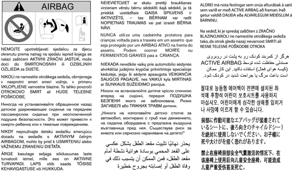
382 m
BATTERY DISPOSAL. The NISSAN GREEN PROGRAM symbol indicates environmentally friendly information and best practices.
 ECO-MICRA The NISSAN GREEN PROGRAM symbol indicates environmentally friendly information and best practices. This symbol means Do not do this or Do not let this happen. BATTERY DISPOSAL CAUTION An improperly
Foreword MODIFICATION OF YOUR VEHICLE IMPORTANT SAFETY INFORMATION REMINDERS FOR SAFETY! READ FIRST THEN DRIVE SAFELY WHEN READING THE MANUAL
 Foreword Welcome to the growing family of new INFINITI owners. This vehicle has been delivered to you with confidence. It has been produced using the latest techniques and strict quality control. This
For your safety, read carefully and keep in this vehicle. Owner s Manual
 For your safety, read carefully and keep in this vehicle. QX70 Owner s Manual Foreword Welcome to the growing family of new INFINITI owners. This vehicle is delivered to you with confidence. It is produced
10/2010 OM10E-0K13E0E
 NOTE Owner's Manual Foreword Welcome to the growing family of new NISSAN owners. This vehicle has been delivered to you with confidence. It has been produced using the latest techniques and strict quality
QASHQAI OWNER'S MANUAL
 QASHQAI OWNER'S MANUAL Foreword Welcome to the growing family of new NISSAN owners. This vehicle has been delivered to you with confidence. It has been produced using the latest techniques and strict quality
WARNING IMPORTANT SAFETY INFORMA- TION REMINDERS FOR SAFETY!
 Foreword Welcome to the growing family of new NISSAN owners. This vehicle is delivered to you with confidence. It was produced using the latest techniques and strict quality control. This manual was prepared
2014 cube OWNER S MANUAL. InformationProvidedby: For your safety, read carefully and keep in this vehicle.
 2014 cube OWNER S MANUAL For your safety, read carefully and keep in this vehicle. WHEN READING THE MANUAL This manual includes information for all options available on this model. Therefore, you may
2016 MICRA OWNER S MANUAL. For your safety, read carefully and keep in this vehicle.
 2016 MICRA OWNER S MANUAL For your safety, read carefully and keep in this vehicle. FOREWORD READ FIRST THEN DRIVE SAFELY Welcome to the growing family of new NISSAN owners. This vehicle is delivered to
requirements, assisting you in the safe operation of your vehicle. WARNING IMPORTANT SAFETY INFORMA- TION REMINDERS FOR SAFETY!
 Foreword Welcome to the growing family of new NISSAN owners. This vehicle is delivered to you with confidence. It was produced using the latest techniques and strict quality control. This manual was prepared
InformationProvidedby:
 Foreword Welcome to the growing family of new NISSAN owners. This vehicle is delivered to you with confidence. It was produced using the latest techniques and strict quality control. This manual was prepared
WARNING IMPORTANT SAFETY INFORMA- TION REMINDERS FOR SAFETY!
 Foreword Welcome to the growing family of new NISSAN owners. This vehicle is delivered to you with confidence. It was produced using the latest techniques and strict quality control. This manual was prepared
Thank you for choosing a Mazda. We at Mazda design and build vehicles with complete customer satisfaction in mind.
 J54L_8R34_EE_02H.BOOK Page 1 Monday, July 15, 2002 9:03 AM A Word to Mazda Owners Thank you for choosing a Mazda. We at Mazda design and build vehicles with complete customer satisfaction in mind. To help
WARNING IMPORTANT SAFETY INFORMATION REMINDERS FOR SAFETY!
 Foreword Your INFINITI represents a new way of thinking about vehicle design. It integrates advanced engineering and superior craftsmanship with a simple, refined aesthetic sensitivity associated with
READ FIRST THEN DRIVE SAFELY
 Foreword Your INFINITI represents a new way of thinking about vehicle design. It integrates advanced engineering and superior craftsmanship with a simple, refined aesthetic sensitivity associated with
READ FIRST THEN DRIVE SAFELY
 FOREWORD READ FIRST THEN DRIVE SAFELY Welcome to the growing family of new NISSAN owners. This vehicle is delivered to you with confidence. It was produced using the latest techniques and strict quality
For your safety, read carefully and keep in this vehicle Infiniti G37 Convertible Owner s Manual
 For your safety, read carefully and keep in this vehicle. 2010 Infiniti G37 Convertible Owner s Manual FOREWORD Your INFINITI represents a new way of thinking about vehicle design. It integrates advanced
READ FIRST THEN DRIVE SAFELY
 FOREWORD READ FIRST THEN DRIVE SAFELY Welcome to the growing family of new NISSAN owners. This vehicle is delivered to you with confidence. It was produced using the latest techniques and strict quality
For your safety, read carefully and keep in this vehicle Infiniti EX Owner s Manual
 For your safety, read carefully and keep in this vehicle. 2011 Infiniti EX Owner s Manual FOREWORD Your INFINITI represents a new way of thinking about vehicle design. It integrates advanced engineering
2015 MICRA OWNER S MANUAL. For your safety, read carefully and keep in this vehicle.
 2015 MICRA OWNER S MANUAL For your safety, read carefully and keep in this vehicle. FOREWORD READ FIRST THEN DRIVE SAFELY Welcome to the growing family of new NISSAN owners. This vehicle is delivered to
For your safety, read carefully and keep in this vehicle Infiniti G Convertible Owner s Manual
 For your safety, read carefully and keep in this vehicle. 2011 Infiniti G Convertible Owner s Manual FOREWORD Your INFINITI represents a new way of thinking about vehicle design. It integrates advanced
READ FIRST THEN DRIVE SAFELY
 FOREWORD READ FIRST THEN DRIVE SAFELY Welcome to the growing family of new NISSAN owners. This vehicle is delivered to you with confidence. It was produced using the latest techniques and strict quality
READ FIRST THEN DRIVE SAFELY
 FOREWORD READ FIRST THEN DRIVE SAFELY Welcome to the growing family of new NISSAN owners. This vehicle is delivered to you with confidence. It was produced using the latest techniques and strict quality
OWNER S MANUAL AND MAINTENANCE INFORMATION. For your safety, read carefully and keep in this vehicle.
 2018.5 OWNER S MANUAL AND MAINTENANCE INFORMATION For your safety, read carefully and keep in this vehicle. Owner s Manual Supplement The information contained within this supplement updates the following
READ FIRST THEN DRIVE SAFELY
 Foreword Welcome to the growing family of new NISSAN owners. This vehicle is delivered to you with confidence. It was produced using the latest techniques and strict quality control. This manual was prepared
2017 MICRA OWNER S MANUAL. For your safety, read carefully and keep in this vehicle.
 2017 MICRA OWNER S MANUAL For your safety, read carefully and keep in this vehicle. FOREWORD READ FIRST THEN DRIVE SAFELY Welcome to the growing family of new NISSAN owners. This vehicle is delivered to
READ FIRST THEN DRIVE SAFELY
 FOREWORD READ FIRST THEN DRIVE SAFELY Welcome to the growing family of new NISSAN owners. This vehicle is delivered to you with confidence. It was produced using the latest techniques and strict quality
READ FIRST THEN DRIVE SAFELY
 FOREWORD READ FIRST THEN DRIVE SAFELY Welcome to the growing family of new NISSAN owners. This vehicle is delivered to you with confidence. It was produced using the latest techniques and strict quality
WARNING IMPORTANT SAFETY INFORMA- TION REMINDERS FOR SAFETY!
 Foreword Welcome to the growing family of new NISSAN owners. This vehicle is delivered to you with confidence. It was produced using the latest techniques and strict quality control. This manual was prepared
READ FIRST THEN DRIVE SAFELY
 FOREWORD READ FIRST THEN DRIVE SAFELY Welcome to the growing family of new NISSAN owners. This vehicle is delivered to you with confidence. It was produced using the latest techniques and strict quality
READ FIRST THEN DRIVE SAFELY
 FOREWORD Your INFINITI represents a new way of thinking about vehicle design. It integrates advanced engineering and superior craftsmanship with a simple, refined aesthetic sensitivity associated with
Foreword MODIFICATION OF YOUR VEHICLE IMPORTANT SAFETY INFORMATION REMINDERS FOR SAFETY! READ FIRST THEN DRIVE SAFELY WHEN READING THE MANUAL
 Foreword Welcome to the growing family of new NISSAN owners. This vehicle has been delivered to you with confidence. It has been produced using the latest techniques and strict quality control. This manual
2012 VERSA SEDAN OWNER S MANUAL. For your safety, read carefully and keep in this vehicle.
 2012 VERSA SEDAN OWNER S MANUAL For your safety, read carefully and keep in this vehicle. FOREWORD READ FIRST THEN DRIVE SAFELY Welcome to the growing family of new NISSAN owners. This vehicle is delivered
WARNING IMPORTANT SAFETY INFORMA- TION REMINDERS FOR SAFETY!
 Foreword Welcome to the growing family of new NISSAN owners. This vehicle is delivered to you with confidence. It was produced using the latest techniques and strict quality control. This manual was prepared
READ FIRST THEN DRIVE SAFELY
 FOREWORD READ FIRST THEN DRIVE SAFELY Welcome to the growing family of new NISSAN owners. This vehicle is delivered to you with confidence. It was produced using the latest techniques and strict quality
READ FIRST THEN DRIVE SAFELY
 Foreword Your INFINITI represents a new way of thinking about vehicle design. It integrates advanced engineering and superior craftsmanship with a simple, refined aesthetic sensitivity associated with
READ FIRST THEN DRIVE SAFELY
 FOREWORD READ FIRST THEN DRIVE SAFELY Welcome to the growing family of new NISSAN owners. This vehicle is delivered to you with confidence. It was produced using the latest techniques and strict quality
FOREWORD WARNING. of your vehicle.
 FOREWORD Your INFINITI represents a new way of thinking about vehicle design. It integrates advanced engineering and superior craftsmanship with a simple, refined aesthetic sensitivity associated with
READ FIRST THEN DRIVE SAFELY
 Foreword Your INFINITI represents a new way of thinking about vehicle design. It integrates advanced engineering and superior craftsmanship with a simple, refined aesthetic sensitivity associated with
READ FIRST THEN DRIVE SAFELY
 FOREWORD READ FIRST THEN DRIVE SAFELY Welcome to the growing family of new NISSAN owners. This vehicle is delivered to you with confidence. It was produced using the latest techniques and strict quality
For your safety, read carefully and keep in this vehicle Infiniti Q60 Convertible Owner s Manual
 For your safety, read carefully and keep in this vehicle. 2014 Infiniti Q60 Convertible Owner s Manual Foreword Your INFINITI represents a new way of thinking about vehicle design. It integrates advanced
READ FIRST THEN DRIVE SAFELY
 FOREWORD READ FIRST THEN DRIVE SAFELY Welcome to the growing family of new NISSAN owners. This vehicle is delivered to you with confidence. It was produced using the latest techniques and strict quality
2013 VERSA SEDAN OWNER S MANUAL. safety, read carefully and keep in this vehicle.
 2013 VERSA SEDAN OWNER S MANUAL For your safety, read carefully and keep in this vehicle. FOREWORD READ FIRST THEN DRIVE SAFELY Welcome to the growing family of new NISSAN owners. This vehicle is delivered
READ FIRST THEN DRIVE SAFELY
 FOREWORD READ FIRST THEN DRIVE SAFELY Welcome to the growing family of new NISSAN owners. This vehicle is delivered to you with confidence. It was produced using the latest techniques and strict quality
2018 OWNER S MANUAL AND MAINTENANCE INFORMATION. For your safety, read carefully and keep in this vehicle.
 2018 OWNER S MANUAL AND MAINTENANCE INFORMATION For your safety, read carefully and keep in this vehicle. Foreword Your INFINITI represents a new way of thinking about vehicle design. It integrates advanced
WARNING IMPORTANT SAFETY INFORMA- TION REMINDERS FOR SAFETY!
 Foreword Welcome to the growing family of new NISSAN owners. This vehicle is delivered to you with confidence. It was produced using the latest techniques and strict quality control. This manual was prepared
InformationProvidedby:
 Foreword Welcome to the growing family of new NISSAN owners. This vehicle is delivered to you with confidence. It was produced using the latest techniques and strict quality control. This manual was prepared
requirements, assisting you in the safe operation of your vehicle. WARNING IMPORTANT SAFETY INFORMA- TION REMINDERS FOR SAFETY!
 Foreword Welcome to the growing family of new NISSAN owners. This vehicle is delivered to you with confidence. It was produced using the latest techniques and strict quality control. This manual was prepared
READ FIRST THEN DRIVE SAFELY
 FOREWORD READ FIRST THEN DRIVE SAFELY Welcome to the growing family of new NISSAN owners. This vehicle is delivered to you with confidence. It was produced using the latest techniques and strict quality
requirements, assisting you in the safe operation of your vehicle. WARNING IMPORTANT SAFETY INFORMA- TION REMINDERS FOR SAFETY!
 Foreword Welcome to the growing family of new NISSAN owners. This vehicle is delivered to you with confidence. It was produced using the latest techniques and strict quality control. This manual was prepared
2010 TITAN OWNER'S MANUAL. For your safety, read carefully and keep in this vehicle.
 2010 TITAN OWNER'S MANUAL For your safety, read carefully and keep in this vehicle. FOREWORD READ FIRST THEN DRIVE SAFELY Welcome to the growing family of new NISSAN owners. This vehicle is delivered to
READ FIRST THEN DRIVE SAFELY
 FOREWORD READ FIRST THEN DRIVE SAFELY Welcome to the growing family of new NISSAN owners. This vehicle is delivered to you with confidence. It was produced using the latest techniques and strict quality
2010 Infiniti M35/M45 Owner's Manual
 2010 Infiniti M35/M45 Owner's Manual FOREWORD Your INFINITI represents a new way of thinking about vehicle design. It integrates advanced engineering and superior craftsmanship with a simple, refined aesthetic
WARNING IMPORTANT SAFETY INFORMA- TION REMINDERS FOR SAFETY!
 Foreword Welcome to the growing family of new NISSAN owners. This vehicle is delivered to you with confidence. It was produced using the latest techniques and strict quality control. This manual was prepared
READ FIRST THEN DRIVE SAFELY
 FOREWORD READ FIRST THEN DRIVE SAFELY Welcome to the growing family of new NISSAN owners. This vehicle is delivered to you with confidence. It was produced using the latest techniques and strict quality
2016 MAXIMA OWNER S MANUAL. For your safety, read carefully and keep in this vehicle.
 2016 MAXIMA OWNER S MANUAL For your safety, read carefully and keep in this vehicle. FOREWORD READ FIRST THEN DRIVE SAFELY Welcome to the growing family of new NISSAN owners. This vehicle is delivered
2010 MAXIMA OWNER S MANUAL. For your safety, read carefully and keep in this vehicle.
 2010 MAXIMA OWNER S MANUAL For your safety, read carefully and keep in this vehicle. FOREWORD READ FIRST THEN DRIVE SAFELY Welcome to the growing family of new NISSAN owners. This vehicle is delivered
READ FIRST THEN DRIVE SAFELY
 FOREWORD READ FIRST THEN DRIVE SAFELY Welcome to the growing family of new NISSAN owners. This vehicle is delivered to you with confidence. It was produced using the latest techniques and strict quality
2011 VERSA OWNER S MANUAL. For your safety, read carefully and keep in this vehicle.
 2011 VERSA OWNER S MANUAL For your safety, read carefully and keep in this vehicle. FOREWORD READ FIRST THEN DRIVE SAFELY Welcome to the growing family of new NISSAN owners. This vehicle is delivered to
2012 NV1500/NV2500 HD/NV3500 HD
 2012 NV1500/NV2500 HD/NV3500 HD OWNER S MANUAL For your safety, read carefully and keep in this vehicle. FOREWORD READ FIRST THEN DRIVE SAFELY Welcome to the growing family of new NISSAN owners. This vehicle
2013 NV200 COMPACT CARGO
 2013 NV200 COMPACT CARGO OWNER S MANUAL For your safety, read carefully and keep in this vehicle. FOREWORD READ FIRST THEN DRIVE SAFELY Welcome to the growing family of new NISSAN owners. This vehicle
For your safety, read carefully and keep in this vehicle Infiniti QX50 Owner s Manual
 For your safety, read carefully and keep in this vehicle. 2014 Infiniti QX50 Owner s Manual Foreword Your INFINITI represents a new way of thinking about vehicle design. It integrates advanced engineering
READ FIRST THEN DRIVE SAFELY
 FOREWORD READ FIRST THEN DRIVE SAFELY Welcome to the growing family of new NISSAN owners. This vehicle is delivered to you with confidence. It was produced using the latest techniques and strict quality
2011 MAXIMA OWNER S MANUAL. For your safety, read carefully and keep in this vehicle. InformationProvidedby:
 2011 MAXIMA OWNER S MANUAL For your safety, read carefully and keep in this vehicle. FOREWORD READ FIRST THEN DRIVE SAFELY Welcome to the growing family of new NISSAN owners. This vehicle is delivered
READ FIRST THEN DRIVE SAFELY
 FOREWORD READ FIRST THEN DRIVE SAFELY Welcome to the growing family of new NISSAN owners. This vehicle is delivered to you with confidence. It was produced using the latest techniques and strict quality
2018 KICKS. OWNER S MANUAL and MAINTENANCE INFORMATION. For your safety, read carefully and keep in this vehicle.
 2018 KICKS OWNER S MANUAL and MAINTENANCE INFORMATION For your safety, read carefully and keep in this vehicle. CALIFORNIA PROPOSITION 65 WARNING WARNING Operating, servicing and maintaining a passenger
READ FIRST THEN DRIVE SAFELY
 Foreword Your INFINITI represents a new way of thinking about vehicle design. It integrates advanced engineering and superior craftsmanship with a simple, refined aesthetic sensitivity associated with
READ FIRST THEN DRIVE SAFELY
 FOREWORD READ FIRST THEN DRIVE SAFELY Welcome to the growing family of new NISSAN owners. This vehicle is delivered to you with confidence. It was produced using the latest techniques and strict quality
READ FIRST THEN DRIVE SAFELY
 FOREWORD READ FIRST THEN DRIVE SAFELY Welcome to the growing family of new NISSAN owners. This vehicle is delivered to you with confidence. It was produced using the latest techniques and strict quality
READ FIRST THEN DRIVE SAFELY
 Foreword Your INFINITI represents a new way of thinking about vehicle design. It integrates advanced engineering and superior craftsmanship with a simple, refined aesthetic sensitivity associated with
WARNING IMPORTANT SAFETY INFORMA- TION REMINDERS FOR SAFETY!
 Foreword Welcome to the growing family of new NISSAN owners. This vehicle is delivered to you with confidence. It was produced using the latest techniques and strict quality control. This manual was prepared
Owner s Manual Supplement
 Owner s Manual Supplement The information contained within this supplement revises the TIRE CHAINS information in the Maintenance and do-it-yourself section of the 2011-2013 Nissan Quest Owner s Manual.
SECTION 1 6 INSTRUMENTS AND CONTROLS. Comfort adjustment. Front seat... 42
 SECTION 1 6 INSTRUMENTS AND CONTROLS Comfort adjustment Front seat................................................ 42 Headrests............................................... 44 Tilt and telescopic steering
READ FIRST THEN DRIVE SAFELY
 FOREWORD READ FIRST THEN DRIVE SAFELY Welcome to the growing family of new NISSAN owners. This vehicle is delivered to you with confidence. It was produced using the latest techniques and strict quality
READ FIRST THEN DRIVE SAFELY
 FOREWORD READ FIRST THEN DRIVE SAFELY Welcome to the growing family of new NISSAN owners. This vehicle is delivered to you with confidence. It was produced using the latest techniques and strict quality
WARNING IMPORTANT SAFETY INFORMA- TION REMINDERS FOR SAFETY!
 Foreword Welcome to the growing family of new NISSAN owners. This vehicle is delivered to you with confidence. It was produced using the latest techniques and strict quality control. This manual was prepared
2015 VERSA SEDAN OWNER S MANUAL. For your safety, read carefully and keep in this vehicle.
 2015 VERSA SEDAN OWNER S MANUAL For your safety, read carefully and keep in this vehicle. FOREWORD READ FIRST THEN DRIVE SAFELY Welcome to the growing family of new NISSAN owners. This vehicle is delivered
2017 VERSA NOTE. OWNER S MANUAL and MAINTENANCE INFORMATION. For your safety, read carefully and keep in this vehicle.
 2017 VERSA NOTE OWNER S MANUAL and MAINTENANCE INFORMATION For your safety, read carefully and keep in this vehicle. FOREWORD READ FIRST THEN DRIVE SAFELY Welcome to the growing family of new NISSAN owners.
Seat belts GENERAL INFORMATION
 Seat belts GENERAL INFORMATION Seat belts are designed to bear upon the bony structure of the body and should be worn low across the pelvis or pelvis, chest and shoulders, as applicable; wearing the lap
READ FIRST THEN DRIVE SAFELY
 FOREWORD READ FIRST THEN DRIVE SAFELY Welcome to the growing family of new NISSAN owners. This vehicle is delivered to you with confidence. It was produced using the latest techniques and strict quality
READ FIRST THEN DRIVE SAFELY
 FOREWORD READ FIRST THEN DRIVE SAFELY Welcome to the growing family of new NISSAN owners. This vehicle is delivered to you with confidence. It was produced using the latest techniques and strict quality
2017 VERSA SEDAN. OWNER S MANUAL and MAINTENANCE INFORMATION. For your safety, read carefully and keep in this vehicle.
 2017 VERSA SEDAN OWNER S MANUAL and MAINTENANCE INFORMATION For your safety, read carefully and keep in this vehicle. FOREWORD READ FIRST THEN DRIVE SAFELY Welcome to the growing family of new NISSAN owners.
2010 PATHFINDER OWNER S MANUAL. For your safety, read carefully and keep in this vehicle.
 2010 PATHFINDER OWNER S MANUAL For your safety, read carefully and keep in this vehicle. FOREWORD READ FIRST THEN DRIVE SAFELY Welcome to the growing family of new NISSAN owners. This vehicle is delivered
2012 XTERRA OWNER S MANUAL. For your safety, read carefully and keep in this vehicle. InformationProvidedby:
 2012 XTERRA OWNER S MANUAL For your safety, read carefully and keep in this vehicle. FOREWORD READ FIRST THEN DRIVE SAFELY Welcome to the growing family of new NISSAN owners. This vehicle is delivered
READ FIRST THEN DRIVE SAFELY
 Foreword GUID-E7E6B9D7-70D5-46FD-8070-D86AD68B3005 Welcome to the growing family of new NISSAN owners. This vehicle is delivered to you with confidence. It was produced using the latest techniques and
2014 SENTRA OWNER S MANUAL. For your safety, read carefully and keep in this vehicle.
 2014 SENTRA OWNER S MANUAL For your safety, read carefully and keep in this vehicle. FOREWORD READ FIRST THEN DRIVE SAFELY Welcome to the growing family of new NISSAN owners. This vehicle is delivered
2018 MAXIMA. OWNER S MANUAL and MAINTENANCE INFORMATION. For your safety, read carefully and keep in this vehicle.
 2018 MAXIMA OWNER S MANUAL and MAINTENANCE INFORMATION For your safety, read carefully and keep in this vehicle. FOREWORD READ FIRST THEN DRIVE SAFELY This manual was prepared to help you understand the
2010 XTERRA OWNER S MANUAL. For your safety, read carefully and keep in this vehicle. InformationProvidedby:
 2010 XTERRA OWNER S MANUAL For your safety, read carefully and keep in this vehicle. FOREWORD READ FIRST THEN DRIVE SAFELY Welcome to the growing family of new NISSAN owners. This vehicle is delivered
READ FIRST THEN DRIVE SAFELY
 Foreword Your INFINITI represents a new way of thinking about vehicle design. It integrates advanced engineering and superior craftsmanship with a simple, refined aesthetic sensitivity associated with
2016 MURANO OWNER S MANUAL. For your safety, read carefully and keep in this vehicle.
 2016 MURANO OWNER S MANUAL For your safety, read carefully and keep in this vehicle. FOREWORD READ FIRST THEN DRIVE SAFELY Welcome to the growing family of new NISSAN owners. This vehicle is delivered
2018 VERSA NOTE. OWNER S MANUAL and MAINTENANCE INFORMATION. For your safety, read carefully and keep in this vehicle.
 2018 VERSA NOTE OWNER S MANUAL and MAINTENANCE INFORMATION For your safety, read carefully and keep in this vehicle. FOREWORD READ FIRST THEN DRIVE SAFELY This manual was prepared to help you understand
Airbags SAFETY INFORMATION. Your vehicle is equipped with several types of airbags: front airbags, side airbags, and side curtain airbags.
 Airbags Your vehicle is equipped with several types of airbags: front airbags, side airbags, and side curtain airbags. Front Airbags (SRS) The front SRS airbags inflate in a moderate-to-severe frontal
2018 PATHFINDER. OWNER S MANUAL and MAINTENANCE INFORMATION. For your safety, read carefully and keep in this vehicle.
 2018 PATHFINDER OWNER S MANUAL and MAINTENANCE INFORMATION For your safety, read carefully and keep in this vehicle. FOREWORD READ FIRST THEN DRIVE SAFELY Welcome to the growing family of new NISSAN owners.
READ FIRST THEN DRIVE SAFELY
 FOREWORD READ FIRST THEN DRIVE SAFELY Welcome to the growing family of new INFINITI owners. This vehicle is delivered to you with confidence. It was produced using the latest techniques and strict quality
2018 MURANO. OWNER S MANUAL and MAINTENANCE INFORMATION. For your safety, read carefully and keep in this vehicle.
 2018 MURANO OWNER S MANUAL and MAINTENANCE INFORMATION For your safety, read carefully and keep in this vehicle. FOREWORD READ FIRST THEN DRIVE SAFELY This manual was prepared to help you understand the
2012 ALTIMA OWNER S MANUAL. For your safety, read carefully and keep in this vehicle.
 2012 ALTIMA OWNER S MANUAL For your safety, read carefully and keep in this vehicle. FOREWORD READ FIRST THEN DRIVE SAFELY Welcome to the growing family of new NISSAN owners. This vehicle is delivered
Z OWNER S MANUAL. InformationProvidedby: For your safety, read carefully and keep in this vehicle.
 2016 370Z OWNER S MANUAL For your safety, read carefully and keep in this vehicle. Foreword Welcome to the growing family of new NISSAN owners. This vehicle is delivered to you with confidence. It was
2011 XTERRA OWNER S MANUAL. For your safety, read carefully and keep in this vehicle.
 2011 XTERRA OWNER S MANUAL For your safety, read carefully and keep in this vehicle. FOREWORD READ FIRST THEN DRIVE SAFELY Welcome to the growing family of new NISSAN owners. This vehicle is delivered
Seat, seatbelt and SRS airbags
 Front seats... 1-2 Manual seat (if equipped)... 1-3 Power seat (if equipped)... 1-4 Head restraint adjustment... 1-8 Seat heater (if equipped)... 1-8 Rear seats... 1-9 Reclining the seatback (Outback)...
Chevrolet Equinox Fuel Cell Owner Manual M
 Chevrolet Equinox Fuel Cell Owner Manual M Seats and Restraint Systems... 1-1 Front Seats... 1-2 Rear Seats... 1-10 Safety Belts... 1-12 Child Restraints... 1-32 Airbag System... 1-54 Restraint System
2018 VERSA SEDAN. OWNER S MANUAL and MAINTENANCE INFORMATION. For your safety, read carefully and keep in this vehicle.
 2018 VERSA SEDAN OWNER S MANUAL and MAINTENANCE INFORMATION For your safety, read carefully and keep in this vehicle. FOREWORD READ FIRST THEN DRIVE SAFELY Welcome to the growing family of new NISSAN owners.