120SC SELF COLLETING DRILL
|
|
|
- Shawn Warren
- 5 years ago
- Views:
Transcription

1 Operation & Service Manual /0 0SC - 5 SELF COLLETING DRILL Houston Operation 7007 Pinemont Houston, TX Recoules Operation Zone industrielle - B.P. 8 Avenue Maurice Chevalier 7783 Ozoir-la-Ferriere Cedex France
2
3 Safety Recommendations For your safety and the safety of others, read and understand the safety recommendations and operating instructions before operating any drill motor. Always wear protective equipment:! For additional information on eye protection, read the latest edition of ANSI Z87., Occupational and Educational Eye and Face Protection. This standard is available from the American National Standards Institute, Inc., West 4nd Street, New York, N.Y ! Hearing protection is recommended in high noise areas (above 85dBA). Close proximity of additional tools, reflective surfaces, process noises, etc., can contribute substantially to the sound level experienced by the operator.! WARNING Impact resistant eye protection must be worn while operating or working near this tool. CAUTION Personal hearing protection is recommended when operating or working near this tool. WARNING! CAUTION Before the tool is connected to the air supply, the throttle should be checked for proper operation (i.e., throttle valve moves freely and returns to closed position). Before removing a tool from service or changing drill bits, make sure the air line is shut off and drained of air. This will prevent the tool from operating if the throttle is accidently engaged. Cutting tools used with these drill motors are sharp. Handle them carefully to avoid injury. The collet and mandrel must be inserted into a properly sized pre-drilled hole before starting the tool. An improperly sized predrilled hole prevents the mandrel from engaging the collet and could result in slippage of the tool. An improperly selected collet and mandrel can also result in slippage of the tool.! WARNING Wear respirator where necessary. Drilling or other use of this tool may produce hazardous fumes and/or dust. To avoid adverse health effects utilize adequate ventilation and/or a respirator. Read the material safety data sheet of any cutting fluids or materials involved in the drilling process.! CAUTION Do not wear loose fitting clothes, long hair, gloves, ties or jewelry. Follow good machine shop practices. Rotating shafts and moving components entangle and entrap, and may result in serious injuries. Never wear long hair, loose-fitting clothes, gloves, ties, or jewelry when working with or near a drill of any type. Quackenbush drills are designed to operate on 90psig (6. bar) maximum air pressure using the proper hose. Excessive air pressure increases the loads and stresses on tool parts and drills, and may result in breakage. The installation of a filter-regulatorlubricator in the air supply line ahead of the tool is highly recommended. Some non-ferrous metal chips (or dusts) are combustible. Examples: Aluminum, magnesium, Titanium, and Zirconium. See the material safety data sheets for combustibility of materials drilled. Never collect spark generating material with combustible material. Examples: Collecting both steel and aluminum or steel and titanium.! CAUTION Slip and fall hazard. Lubricant and coolant systems must be properly maintained to avoid leakage. Hoses must be organized and care taken to avoid tripping. Quackenbush drills are often used with lubricant or cooling systems which must be properly maintained to avoid leakage. Failure to do so can result in serious injuries from slipping on oily surfaces. 3
4 Safety Recommendations! WARNING Keep hands away from clamping and feed mechanisms. Clamp mechanism moves when drilling and connecting or removing air supply. Due to the number and variety of tooling applications, the user's methods engineering departments, ect., must consider any hazards that may be associated with each specific application of this product and provide adequate operator protection from inadvertent contact with any moving components. The clamping and feed mechanisms of self-colleting drill motors are exposed for visibility and can move when the air supply is connected or disconnected. To avoid injury, keep fingers and hands away from these areas when handling or operating this tool. Any tool operator should be aware of the following warning signs and symptoms so that a problem can be addressed before it becomes a debilitating injury. Any user suffering from prolonged symptoms of tingling, numbness, blanching of fingers, clumsiness or weakened grip, inability to hold objects, nocturnal pain in the hand, or any other disorder of the shoulders, arms, wrists, or fingers should notify their employer so that a review of what steps might be taken to prevent further occurances. These steps might include but are not limited to, repositioning the workpiece or redesigning the workstation, reassigning tool users to other jobs, rotating jobs, changing worker pace, and/or changing the type of tool used so as to minimize stress on the operator. Some tasks may require more than one type of tool to obtain the optimum operator/ tool/ task relationship. Avoid OK Avoid Avoid OK Avoid! WARNING Repetitive work motions can injure your hands and arms.! WARNING Exposure to vibration can injure your hands and arms. Some individuals are susceptible to disorders of the hands and arms when exposed to vibration and/or tasks which involve repetitive work motions. Those individuals predisposed to vasculatory or circulatory problems may be particularly susceptible. Cumulative trauma disorders such as carpal tunnel syndrome and tendinitis can be caused or aggravated by repetitious, forceful exertions of the hands and arms. These disorders develop gradually over periods of weeks, months, and years. Tasks should be performed in such a manner that the wrists are maintained in a neutral position, which is not flexed, hyperextended, or turned side to side. Stressful postures should be avoided and can be controlled through tool selection and work location. Extension Neutral Flexion Radial Deviation Neutral Ulnar Deviation The following recommendations will help reduce or moderate the effects of repetitive work motions. The operator of any drill should: Use a minimum hand grip force consistent with proper control and safe operation Keep body and hands warm and dry Avoid anything that inhibits blood circulation Smoking Tobacco Cold Temperatures Certain Drugs Avoid awkward postures Keep wrists as straight as possible Interrupt work, activities, or rotate jobs to provide periods free from repetitive work motions. 4
5 ! Safety Recommendations Safety Labels The safety labels found on this tool are an essential part of this product. Labels should not be removed. Labels should be checked periodically for legibility. Replace safety labels when missing or when the information can no longer be read. Replacement labels can be ordered by the part numbers shown on this page WARNING 644 Keep hands away from clamping and feed mechanisms. Clamp mechanism moves when drilling and connecting or removing air supply.! WARNING - Wear impact resistant eye protection. - Hearing protection is recommended. - Avoid contact with rotating spindle or cutter. - Wear respirator as necessary. - Exposure to repetitive work motion and/or vibration may be harmful to your hands and arms OPERATING INSTRUCTIONS 0345! CAUTION Read operating instructions before operating tool ! Keep hands away from this area when handling or operating tool. Clamp mechanism moves when drilling and connecting or removing air supply. WARNING 5


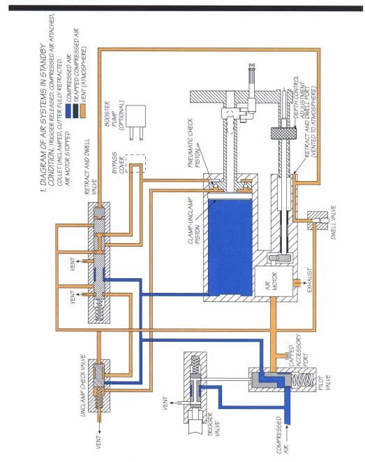
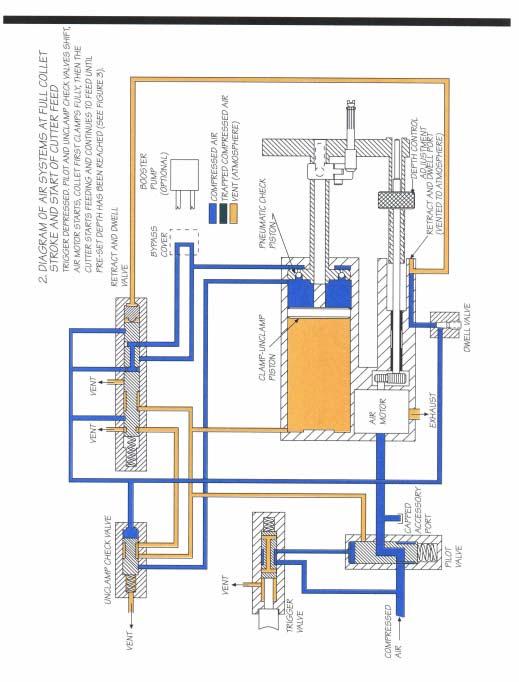
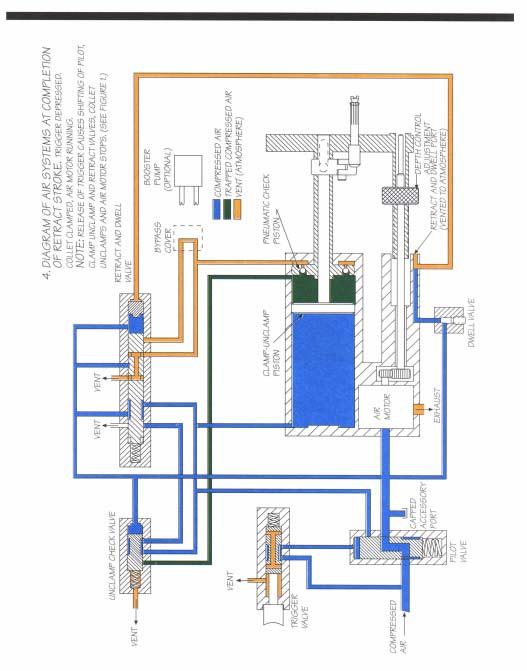
6 Index Safety Recommendations Major Tool Components Introduction and General Information Air System Diagrams Backhead Disassembly Air Motor Disassembly Spindle Adjustment Quill & Pressure Foot Removal How to Change Quills Feed Clamp Disassembly Dwell Valve Disassembly Disassembly of Feed Control Plug Unclamp Check Valve Disassembly Retract and Dwell Valve Disassembly Hydraulic Fluid Reservoir Disassembly Trigger Disassembly Pilot Valve Disassembly Tool Adjustments Drill Assembly Gear Set Assemblies Accessories Template Boss Jig Collet Foot Attachments High Curvature Pad Assembly Booster Pump Assembly Mist Lubricators Trouble Shooting & Maintenance Kit Major Tool Components Spindle Adjustment Dwell Adjustment Depth Control Nut Depth Control Clamp Feed Sleeve Motor Exhaust Backhead Spindle Adjustment Clamp Bypass Cover Template Boss (See Accessories) Trigger Lock Trigger Variable Spacing Pressure Foot Adjustable Tail Pad Air Inlet Bushing (3/8-8 FNPT) Special Tools Feed Rate Adjustment Pressure Foot Nut Tool (6304) Collet Guide Accessory Air Port (50-8 NPT) Trigger Lock Tool (6305) 6
7 Introduction and General Information The Q-Matic 0SC-5 are air operated, hydraulically controlled tool that automatically clamps to the material, drills and countersinks close tolerance holes in one operation. The Q-Matic will produce high quality holes in aluminum, steel, titanium and petroleum hybrid materials primarily found in the aircraft/aerospace industries. The Q-Matic self-colleting drill motor has been designed using state-ofthe-art technology that provides maximum power,minimum weight and the highest degree of accuracy for demanding hole preparation requirements. Technical Data Feed Stroke: Feed stroke of the Q-Matic 0SC-5 is.5 inches to drill and countersink in inch stacked material. The feed stroke is unaffected by the collet stroke. Collet Stroke: The Q-Matic 0SC-5 will clamp throughout its.875 inch stroke. Collet stroke is unaffected by feed stroke. Spindle Adjustment: The spindle adjustment of.375 inch allows for drill length variations. See Spindle Adjustment information on page 5. Countersink Depth Control: A micrometer adjustment provides for countersink stop repeatability within.00 inch. Cutter Sizes: The Q-Matic 0SC-5 will accommodate.500 diameter drills without countersink and.78 countersink diameter. Feed Rate: An adjustable drill feed rate mechanism enables the Q-Matic 0SC-5 to drill from 5 seconds per inch to minute per inch. See Feed Rate Adjustment information on page 5. Cutter to Collet Spacing: The cutter to collet distance is adjustable between.00 inch minimum to 3.50 inch maximum. Coolant: The Q-Matic 0SC-5 has a drill point coolant port in the pressure foot. A coolant mist lubricator is available (See Accessories Page 33-34) Air Motor: The air motor for the 0SC-5 is rated at. horsepower nominal when supplied with air at 90 p.s.i. Air Consumption: Air consumption of the Q-Matic 0SC- 5 is 45 c.f.m. at 90 p.s.i. dynamic. Weight: 5SC-5 weight with the aluminum pressure foot is 3 pounds. Spindle Speeds: Eleven geared spindle speeds are available with the 0SC-5: 70, 470, 700, 900,,50,,00, 3,500, 5,500, 7,000, 4,000, 3,5000 RPM. See pages 30 thru 3 for gear set assembly configurations. Any gear set can be used with the 0SC-5 tool. See pages 3 thru 3 for gear set assembly configurations. Trigger Lock: A trigger lock is provided which allows the tool to be locked in the "Operate" position. With the lock activated, the tool will run through the clamp, feed and retract cycles, but it will not unclamp or stop the motor until the trigger lock is manually released. Tool Start-Up The Q-Matic 0SC-5 drill is shipped from the factory equipped to the customer's specifications: spindle RPM, spindle to accommodate cutter type desired, pressure foot type, collet guide to accommodate collet desired and optional booster pump (if required). After unpacking, examine the customer-specified equipment on the Q-Matic tool to verify type and speed of components. Attach air line to 3/8-8 NPT inlet bushing. If quick disconnect fittings are used, 3/8 in. ID are minimum. The Q-Matic 0SC-5 drill requires a supply of clean PSI air. Air consumption is 45 CFM at 90 PSI. The use of the in-line lubricator will provide the proper lubrication for the air motor and will significantly increase the tool life expectancy. Because O-rings are extensively used to seal systems within the tool, the elimination of foreign particles and other contaminants will reduce the possibility of damage to these parts. Always inspect O-rings for damage or wear and replace as required. The use of silicone O-ring lubricant is strongly recommended during reassembly. The addition of oil in the air line will also increase motor and valve life as well as the life of the O-rings. Avoid the use of synthetic lubricants to prevent damage to O-rings and seals. Q-matic 0SC-5 DRILL MOTOR SPECIFICIATIONS WEIGHT 3 LBS. MAX. W/ALUMINUM FOOT AIR CONSUMPTION P.S.I. DYNAMIC HORSE POWER 90 P.S.I. O/A LENGTH 4.8 IN. MAX AT FULL EXTENSION STROKE.5 IN. (DRILL & C/SINK IN. STACK) COLLET STROKE.00 IN. (NO LOSS OF FEED STROKE) COUNTERSINK COUNTERSINK STOP REPEATS WITHIN.00 IN. FEED RATE MIN. 5 SEC. PER INCH, MAX MIN. PER INCH SPINDLE SPEEDS 70, 470, 700, 900,,50,,00, 3,500, 5,500, 7,000, 4,000, 3,5000 DRILLING THRUST 300 LBS. MAX. (WITHOUT BOOSTER PUMP) CLAMP FORCE 450 LBS. MIN. CLAMP FORCE (UNREGULATED AIR) SPINDLE ADJUSTMENT MAX. DRILL SIZES COLLET FOOT SPACING SPINDLE COOLANT.375 IN. ADJUSTMENT TO ALLOW FOR DRILL LENGTH VARIATIONS.500 (NO C/SINK), (.78 C/SINK DIA.).00 IN. MIN IN. MAX..500 IN. DIA. W/4-8 & 3/8-6 IN. THR'D FOR I.D. THREAD TYPE DRILLS OR /4-8 TAPER-LOK TYPE DRILLS. AIR BLAST PORT & DRILL POINT PORT IN TEMPLATE STD., COOLANT MIST LUBRICATOR AVAILABLE. 7
8 8
9 9

10 0
11

12
13 3

14 4
15 5

16 6
17 7
18 8
19 9
20 0

21

22
23 3
24 4
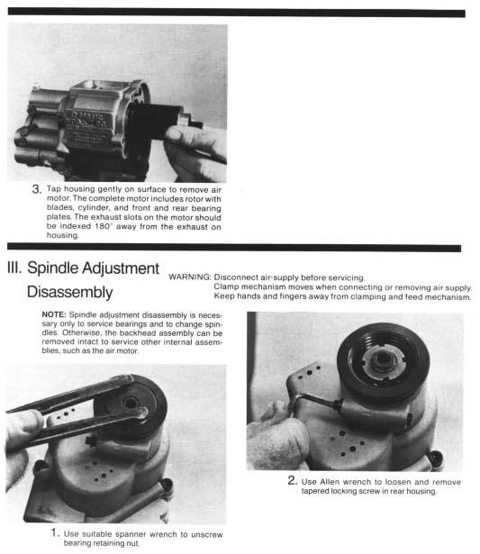
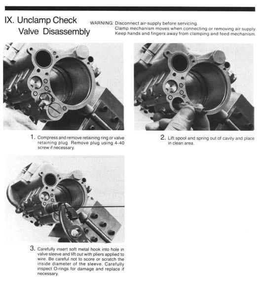
25 Tool Adjustments WARNING: Disconnect air-supply before servicing. Clamp mechanism moves when connecting or removing air supply. Keep hands and fingers away from clamping and feed mechanism. Spindle Stroke Adjustment Loosen spindle adjustment lock, then turn spindle adjustment knob. Right hand rotation advances cutter foward; left hand rotation returns cutter. Correct cutter point position is flush with face of template boss. When cutter is properly adjusted, lightly tighten spindle adjustment lock to hold adjustment. Micrometer Depth Adjustment Loosen adjustment clamp, and rotate depth adjustment nut. Clockwise rotation decreases depth; counterclockwise increases depth. Graduations scribed on barrel are in.00" increments. When proper depth is achieved. lightly tighten adjustment clamp. Feed Rate Adjustment With appropriate tool, turning feed rate adjustment counterclockwise, increase feed rate. Turning the screw clockwise decreases feed rate. Feed rate can be measured by using the following formula: 60 seconds Time to drill one inch = Feed Rate x Spindle Speed (rpm) Dwell Adjustment Insert appropriate size allen wrench into dwell adjustment valve opening. Rotate wrench clockwise until valve seats lightly. Rotate valve counterclockwise / turn to obtain base setting. Note: If adjustment valve is opened too far, drill motor will not cycle, and feed cycle cannot be obtained. To correct, turn valve clockwise to seat valve and set according to instructions above. If valve is closed too far, retract cycle cannot be obtained. To correct, turn valve counterclockwise and set according to instructions. Closing valve increases countersink dwell time; opening valve decreases countersink dwell time. Tail Pad Adjustment The purpose of the tail pad is to compensate for slght surface curvature of the workpiece being drilling and to assure that the hole being drilled is perpendicular to the surface. To adjust to a flat plane for drilling flat surfaces, use a straight edge between the tail pad and face of template boss and adjust the tail pad until the straight edge is flush with the face of the template boss. An optional tail pad is available for high curvature surfaces. ( See Accessories for more information.) 5
26 Muffler Subassembly ITEM PART NO. PART NAME QTY BOX, MUFFLER 636 ELEMENT, MUFFLER PLENUM SCREW, SHC (0-4UNC-3A) 5** 635 SCREW, HSBHC (0-3UNF X.50) ** PARTS NOT INCLUDED IN SUBASSEMBLY: SCREWS 5SC Upgrade to 0SC Subassembly Part No. Name of Part Quanity Spacer, Pilot Valve Subassembly, Pilot Valve Fitting Subassembly, Gear Plate Spacer Screw, HSBHC (0-3UNF X.50) Screw, Indexing Bushing, Inlet Valve, In-line Non return Subassembly, Muffler 6
27 SPINDLE SET SPINDLE GEAR SHOWN ONLY 634 SEE SPECIFIC GEAR ASSEMBLIES ASSEMBLE FOR ASSEMBLY INSTRUCTIONS 6700 BACK-TO-BACK Muffler Assy PRESSUE FOOT - RIGHT HAND PRESSUE FOOT - LEFT HAND COLLET AND MANDREL SHOWN BUT NOT SUPPLIED WITH THIS ASS'Y SECTION A-A DIA DIA DIA
28 (8 REQ'D) ( REQ'D) C A B SECTION C-C 6056 (3 REQ'D) (4 REQ'D) B C A (3 REQ'D) SECTION B-B
29 6053 (3 REQ'D) (3 REQ'D) ( REQ'D) USE LOCTITE ON TH'DS - ASSEMBLY,GEAR SET ( REQ'D) (4 REQ'D) ( REQ'D) VIEW D-D 9
30 PARTS LIST Part No. Name of Part Qty. Part No. Name of Part Qty Label; caution Label; warning Pressure foot; right Pressure foot; left Label; warning Washer; plain O-ring Screw; bhc O-ring Ring; retaining O-ring Screw; sfchc Subassy; bushing Valve; needle Screw, bhc (6-3 x.500 lg) Screw; set Screw; shc Trigger Spring Key Pad; pressure Collet guide clip Lift lever pin Plug Spacer Piston Rotor Assy; pilot valve Spring; compression Pipe; plug Ring; retaining Screw; shc Spacer Ring; retaining Spring Pin; trigger lock Bushing; trigger lock Subassy; check valve Screw Holder; collet Bulkhead; rear Piston; clamp-unclamp Nut bearing retaining Bearing; ball Subassy; valve Plate; rear bearing Plate; front bearing Plug; reservoir Cover Ring; retaining Ring; retaining Screw; shc Screw; shc Screw; bhc O-ring O-ring O-ring Locknut Washer; lock Collet spring Spring; compression Washer Non-regulating plug O-ring Screw; orifice Screw; shc Acorn nut Trigger valve assembly Backhead Nut; spindle adjust. Clamp bushing Clamp nut Shaft; clamp Clamp check piston Cover; depth control Nut adjust; depth control Clamp; depth control Cylinder; liner Plug; fluid reservoir Plug; feed control Handle Hydraulic feed control cylinder Flat head cap screw Bracket; feed control Bulkhead; front Nut; pressure foot Bushing; pull rod Pull rod Clevis pin; linkage Clamp-feed shaft Linkage; clevis Lift finger Screw; hsbhc (0-3UNF x.50) Screw Bushing; inlet Pin; spring Ring; retaining Screw; bhc Plug; pressure Screw; set Ring; retaining Collar; rotor Ball (/8) O-ring O-ring O-ring O-ring O-ring O-ring Screw; shc Plug; pipe Screw; sfchc Bearing; ball O-ring Ring; retaining O-ring O-ring O-ring Blade; rotor Cylinder Snap ring Bearing cap O-ring O-ring
31 GEAR SET ASSEMBLIES REF RPM RPM Part No. Name of Part Qty. Assembly, Backhead Assembly, Spacer Plate, Gear Set Gear, Spindle Pinion, Reduction Gear, Reduction Bearing, Ball, Flng Ring, Retaining Key, Woodruff Ring, Retainer Screw, Soc, Hd, Cap Gear Plate Spacer 4 Part No. Name of Part Qty REF Assembly, Backhead Assembly, Spacer Plate, Gear Set Gear, Spindle Pinion, Reduction Gear, Reduction Bearing, Ball, Flng Ring, Retaining Key, Woodruff Screw, Soc, Hd, Cap Gear Plate Spacer 3 4 Backhead Assembly is shown for reference only and is not part of the gear assembly. Spindle Gear is not shown, but is supplied loose with assembly. Retainer Ring is used on the 80 RPM only. Backhead Assembly is shown for reference only and is not part of the gear assembly. Spindle Gear is not shown, but is supplied loose with assembly. Part No. Name of Part Qty REF RPM RPM Assembly, Backhead Assembly, Spacer Plate, Gear Set Gear, Spindle Pinion, Reduction Gear, Reduction Bearing, Ball, Flng Ring, Retaining Key, Woodruff Screw, Soc, Hd, Cap Gear Plate Spacer 3 4 Part No. Name of Part Qty REF Assembly, Backhead Assembly, Spacer Plate, Gear Set Gear, Spindle Pinion, Reduction Gear, Reduction Bearing, Ball, Flng Ring, Retaining Key, Woodruff Screw, Soc, Hd, Cap Gear Plate Spacer 3 4 Backhead Assembly is shown for reference only and is not part of the gear assembly. Spindle Gear is not shown, but is supplied loose with assembly. Backhead Assembly is shown for reference only and is not part of the gear assembly. Spindle Gear is not shown, but is supplied loose with assembly ,50RPM Part No. Name of Part Qty REF Assembly, Backhead Assembly, Spacer Plate, Gear Set Gear, Spindle Pinion, Reduction Gear, Reduction Bearing, Ball, Flng Ring, Retaining Key, Woodruff Screw, Soc, Hd, Cap Gear Plate Spacer ,00RPM Part No. Name of Part Qty REF Assembly, Backhead Assembly, Spacer Plate, Gear Set Gear, Spindle Gear, Reduction Bearing, Ball, Flng Ring, Retaining Screw, Soc, Hd, Cap Gear Plate Spacer 3 4 Backhead Assembly is shown for reference only and is not part of the gear assembly. Spindle Gear is not shown, but is supplied loose with assembly. Backhead Assembly is shown for reference only and is not part of the gear assembly. Spindle Gear is not shown, but is supplied loose with assembly. 3
32 Part No. Name of Part Qty REF ,500RPM Assembly, Backhead Assembly, Spacer Plate, Gear Set Gear, Spindle Pinion, Reduction Gear, Reduction Bearing, Ball, Flng Ring, Retaining Key, Woodruff Screw, Soc, Hd, Cap Gear Plate Spacer ,500RPM Part No. Name of Part Qty REF Assembly, Backhead Assembly, Spacer Plate, Gear Set Gear, Spindle Pinion, Reduction Gear, Reduction Bearing, Ball, Flng Ring, Retaining Key, Woodruff Screw, Soc, Hd, Cap Gear Plate Spacer 3 4 Backhead Assembly is shown for reference only and is not part of the gear assembly. Spindle Gear is not shown, but is supplied loose with assembly. Backhead Assembly is shown for reference only and is not part of the gear assembly. Spindle Gear is not shown, but is supplied loose with assembly ,000RPM Part No. Name of Part Qty REF Assembly, Backhead Assembly, Spacer Plate, Gear Set Gear, Spindle Pinion, Reduction Gear, Reduction Bearing, Ball, Flng Ring, Retaining Key, Woodruff Screw, Soc, Hd, Cap Gear Plate Spacer ,000RPM Part No. Name of Part Qty REF Assembly, Backhead Assembly, Spacer Plate, Gear Set Gear, Spindle Pinion, Reduction Gear, Reduction Gear, Pinion Overlay Bearing, Ball, Flng Ring, Retaining Key, Woodruff Screw, Soc, Hd, Cap Gear Plate Spacer 3 4 Backhead Assembly is shown for reference only and is not part of the gear assembly. Spindle Gear is not shown, but is supplied loose with assembly. Backhead Assembly is shown for reference only and is not part of the gear assembly. Spindle Gear and Pinion Overlay Gear are not shown, but is supplied loose with assembly ,500RPM Part No. Name of Part Qty REF Assembly, Backhead Assembly, Spacer Plate, Gear Set Gear, Spindle Pinion, Reduction Gear, Reduction Gear, Pinion Overlay Bearing, Ball, Flng Ring, Retaining Key, Woodruff Screw, Soc, Hd, Cap Gear Plate Spacer 3 4 GEAR PLATE SHC SCREWS SPACER BACKHEAD REDUCTION GEAR RETAINING RING WOODRUFF KEY ITEM IS FOR REFERENCE ONLY, IT IS NOT PART OF THE SUBASSEMBLY NOTE POSITION OF GEAR SHOULDER SPINDLE GEAR GEAR SET PLATE -B- RETAINER RING IS USED ON 70 RPM ONLY GEAR PLATE BALL SPACER BEARING REDUCTION PINION GEAR Backhead Assembly is shown for reference only and is not part of the gear assembly. Spindle Gear and Pinion Overlay Gear are not shown, but is supplied loose with assembly. 3
33 33
34 34
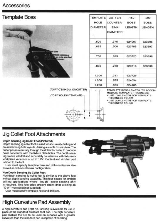
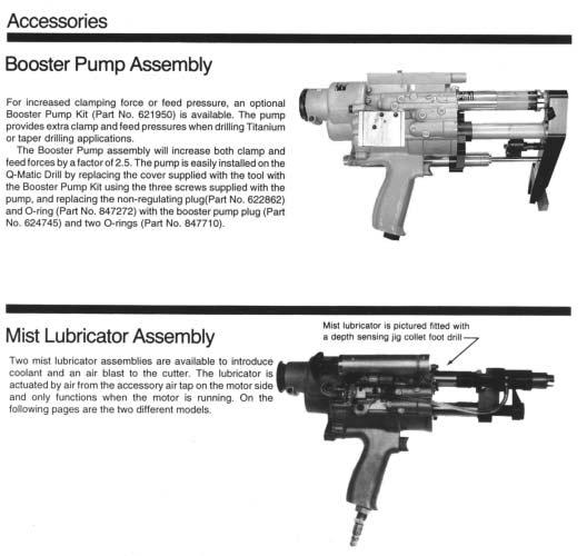
35 Booster Pump Assembly Instructions Booster Pump Assembly 6950 ITEM PART DESCRIPTION NUMBER QTY. NUMBER 6500 Assembly, Body 650 Assembly, End Plate, High Pressure End Plate, Low Pressure Gasket, End Plate, Low Pressure Valve, Pressure Relief Piston, Pressure Relief Valve,Check Valve, Shuttle Piston Spring, Compression, (.34 Length) 6653 Spring, Compression, (.88 Length) ring 3 65 Gasket, End Plate, High Pressure ring ring ring ring Socket Head Cap Screw Socket Head Cap Screw Retaining Ring ring Plug, Booster Pump INSTALLATION INSTRUCTIONS. Remove (3) screws No.6050 and cover No.6768 attached to tool.. Install () 0-rings #7 and () # in booster pump if not already installed. 3. Install booster pump No.648 with (3) screws #9 provided. 4. Remove plug, non-regulating No.686, with slot screwdriver (Refer to service instructions for location). 5. Install () 0-rings #7 onto booster pump plug #. 6. Install booster pump plug #. 35
36 36 Note: x Upper number is item. x Lower number is quantity required. PRESSURE FILL MIST LUBRICATOR
37 Note: x Upper number is item. x Lower number is quantity required. MANUAL FILL MIST LUBRICATOR 37
38 38 4 ITEM PART NO PART NAME 0-4 X 5/8 SFHCS CHECK VALVE QTY. 3 TO TEMPLATE FOOT FITTING FITTING FITTING, MALE ELBOW FITTING, MALE PUSH-IN 8 6 TO NDSJC FOOT TO DSJC FOOT NYLON TUBING PLATE, MOUNTING RESERVOIR, LARGE MANUAL FILL RESERVOIR, SMALL MANUAL FILL RESERVOIR, SMALL PRESSURE FILL RESERVOIR, LARGE PRESSURE FILL MIST LUBRICATORS & MOUNTS COMPLETE SUBASSEMBLIES: MFSC , PFSC MFLC , PFLC TO MOTOR 9 MOUNTING FOR MIST LUBRICATOR
39 TROUBLE SHOOTING SYMPTOM Air motor and/or clamp and feed functions do not start when trigger is depressed. Air motor does not run when trigger is depressed, but feed and clamp functions properly. Air motor idles when trigger valve is released. Motor runs, but clamp & feed functions do not start. Motor runs, clamps but doesn t feed. Lunge during feed or variation in feed rate. Tool doesn t retract at end of feed stroke. Tool retracts shortly after trigger depressed. Tool pulses on retract (rapid feed retract-feed retract ). REASON Trigger or pilot valves clogged with foreign matter. Gears damaged or jammed with debris. Foreign matter in motor inlet. Broken rotor blades, rotor or gear bearings. Pilot valve or retract and dwell valve sticky (not fully reset), or bad O-ring. Leaking O-ring on air motor rear bear- -ing support. Unclamp check valve doesn t shift when trigger is depressed. Feed control valve closed Defective feed control cylinder. Dwell valve seated too tightly. Retract and dwell valve doesn t shift. Depth control adjusted out of the max. range of the tool. Dwell valve opened too far off of seat. Damaged O-rings on retract and dwell valve. MAINTENANCE KIT SOLUTION Remove trigger and pilot valves (separately) and inspect for rust or debris. Inspect O-rings and replace if necessary, With air line disconnected check for free spindle rotation with hex key wrench in end of spindle. Remove backhead, clean and inspect gears for damage. Remove motor and clean debris from motor inlet. Remove motor and inspect rotor blades and bearings. Replace if necessary. Remove and check valves for debris and free movement of spool. Inspect O-rings, lubricate and reassemble. Remove and inspect O-rings. Replace if necessary and reassemble. Remove unclamp check valve and inspect for debris, free movement and damaged O-rings. Lubricate and reassemble. Back off feed control valve counterclockwise until feed commences. Replace feed control cylinder. Back dwell valve off from seat /8 turn to & / turn. Remove retract and dwell valve and inspect for debris, free movement and damaged O-rings. Lubricate and reassemble. Readjust depth control nut within the feed stroke of the tool (ref.:.0 max. stroke). Turn dwell valve clockwise (should be /8 to &/ turns of seat). Remove retract and dwell valve, inspect O-rings and replace as necessary. Lubricate and reassemble. PART NO Tool box Assembly tool Assembly tool, press. Foot nut Assembly tool, trigger lock Assembly tool, pressure hydraulic & front enclosure Assembly tool, pressure foot nut Assembly tool, bulkhead removal Assembly tool, depth stop Removal tool, valve Slide hammer puller Assembly fixture Wrench, spindle bearing locknut Bearing installer Removal tool, feed control valve Removal tool, pilot valve Arbor press fixture Valve installation tool Wrench, feed control valve Tee wrench, foot body Tool, 36SC pull rod bushing Tool, 5/0SC pull rod bushing NAME OF PART QTY. 39
40 40 CooperTools 7007 Pinemont Houston, Texas Phone: (73) Fax: (73)
OPERATING INSTRUCTIONS AND SERVICE MANUAL
 OPERATING INSTRUCTIONS AND SERVICE MANUAL 5ML-.6B- 837 FIXTURIZED NUTRUNNER COMPLETE TOOL MODEL NO. CODE NO. 5ML-.6B-837 230837 READ SAFETY RECOMMENDATIONS BEFORE OPERATING TOOL Printed in U.S.A. 2--97
135DPV-B Series Variable Speed Drills
 Operation & Service Manual 82040 2/0 5DPV-B Series Variable Speed Drills Drill: Series: 5 5 D PV - XX B - XX Drill Chuck: 42 (/8-24B) /4 HD Capacity 4 (/8-24B) /8 HD Capacity 50 (/8-24B) /2 Capacity 5
P-15 & MP-15 SERIES POWER TOOL ANALYZER
 Operation & Service Manual 8373 /0 P-5 & MP-5 SERIES POWER TOOL ANALYZER XX-5 Series: P-5 Inch Pounds Newton-Meters (4-60) (.5-8) Order Number: 8000 MP-5 Centimeter-Kilograms (5-80) 805 Newton-Meters (.5-8)
SERVICE&OPERATING MANUAL INSTRUCTION
 QUALITY TUBE TOOLS KRAIS Tube Expanders SERVICE&OPERATING MANUAL INSTRUCTION For models: K72-RT-90, K72-RT-90-280, K73-RT-190, K73-RT-190-375, K72-LT-90, K72-LT-90-280, K73-LT-190, K73-LT-190-375 READ
SERVICE&OPERATING MANUAL INSTRUCTION
 QUALITY TUBE TOOLS SERVICE&OPERATING MANUAL INSTRUCTION For models: K20-550, K20-1800, K20-2500 READ SAFETY RECOMMENDATIONS BEFORE OPERATING THIS TOOL Poland, 55-106 Zawonia, Czachowo 15 tel. +48 71 312
Torque Controlled Tube Rolling Motor
 TM-82 9-02-05 Torque Controlled Tube Rolling Motor 9040-1800 Operating and Maintenance Instructions Elliott Tool Technologies Ltd 1760 Tuttle Avenue Dayton, Ohio 45403 U.S.A. Phone: +1 800 332 0447 +1
Balance Arms Air Cylinder and Spring Models
 Parts Manual 8385 0/06/0 Balance Arms Air Cylinder and Spring Models For additional product information visit our website at http://www.apextoolgroup.com Safety Recommendations For your safety and the
445 Series Motors. Operating and Maintenance Instructions. Models 445L , 445R , 445L , 445R
 445 Series Motors Models 445L1753-190, 445R1753-190, 445L1752-90, 445R1752-90 Tube & Pipe Cleaners Tube Testers Tube Plugs Tube Removal Tube Installation Operating and Maintenance Instructions www.elliott-tool.com
400QGDBV Series S400 & S600 In-line Positive Feed Drills
 Parts Manual 8 06/0/0 400QGDBV Series S400 & S600 Inline Positive Feed Drills For additional product information visit our website at http://www.apextoolgroup.com Safety Recommendations For your safety
drill point and thru spindle coolant systems positive mechanical depth stop
 SPACEMATIC SPACEMATIC ULTRALITE ULTRALITE Model 1000II Model 2000 TM TM DRILLING MACHINES Standard Features Optional Features ergonomic design air pressure intensifier for increased thrust consistent clamp
air pressure intensifier for increased thrust consistent clamp force min to max collet spacing ergonomic design
 Formerly Hi-Shear Tooling Official Distributor: SPACEMATIC Wm. Lees & Sons Ltd. United Kingdom Telephone: +44 (0) 1698 426662 Email: sales@ Website: ULTRALITE TM DRILLING MACHINES Model 1000II Standard
Airetool Airetrol Rolling Motor. Operating & Service Manual IM 03/23/2012
 Operating & Service Manual 90074-IM 1550-900 Airetrol Rolling Motor For additional product information visit our website at http://www.apextoolgroup.com 90074-IM Description Free Speed Maximum Torque Minimum
88 Series Screwdrivers
 Parts Manual 8308 0/07/0 88 Series Screwdrivers For additional product information visit our website at http://www.apextoolgroup.com Safety Recommendations For your safety and the safety of others, read
MODELS 45 RA 45 RAC 45 RAZ 45 RAS
 General Safety and Maintenance Manual Model Number 45RA 45RAZ 45RAS 45RAC SERIES PNEUMATIC RIGHT ANGLE GRINDER Exhaust Direction Side Throttle Type (L) Lever or (K) Safety Lever Speed 12000 to 14000 R.P.M
AIR DRIVEN TUBE CLEANER
 MODEL PGX-2 AIR DRIVEN TUBE CLEANER OPERATING INSTRUCTIONS & SERVICE MANUAL Rev: A, 5/11/2007 TO REDUCE THE RISK OF INJURY AND EQUIPMENT DAMAGE USER MUST READ AND UNDERSTAND OPERATOR S MANUAL. Thomas C.
Airetool. 720 Series Airetrol Rolling Motor. Operating & Service Manual IM 05/11/2011
 Operating & Service Manual 90014-IM 05/11/2011 Airetool 720 Series Airetrol Rolling Motor Model Number Part Number (Order) 720-550-B 8405391 720-1800-B 8405383 720-2500-B 8405541 For additional product
Airetool AIRETOOL MODEL 720 PISTOL GRIP AIRETROL. Model B ( ) Model B ( ) Model B ( )
 Model B ( ) Model B ( )") OPERATING & SERVICE MANUAL # 90014-IM REV 07/25/01 Airetool AIRETOOL MODEL 720 PISTOL GRIP AIRETROL Model 720-550-B (8405391) Model 720-1800-B (8405383) Model 720-2500-B (8405541) READ SAFETY RECOMMENDATIONS
OPERATING & SERVICE MANUAL # 90014-IM REV 07/25/01 Airetool AIRETOOL MODEL 720 PISTOL GRIP AIRETROL Model 720-550-B (8405391) Model 720-1800-B (8405383) Model 720-2500-B (8405541) READ SAFETY RECOMMENDATIONS
MULTIPLE ACCESSORIES. Type R.P.M. (18000PM is standard) (L) Lever or (K) Safety Lever
 (L) Lever or (K) Safety Lever") HENRY TOOLS Industrial Airtools at Work General Safety and Maintenance Manual S SK MULTIPLE ACCESSORIES CAPACITY -2 Inch (50mm), 3 Inch (75mm) or 4 Inch (100mm) Type 1 wheels. NOTE: GUARD IS REQUIRED if
HENRY TOOLS Industrial Airtools at Work General Safety and Maintenance Manual S SK MULTIPLE ACCESSORIES CAPACITY -2 Inch (50mm), 3 Inch (75mm) or 4 Inch (100mm) Type 1 wheels. NOTE: GUARD IS REQUIRED if
ULTRALITE SPACEMATIC. Nutplate Drillmotor II/IIB DRILLING MACHINES
 SPACEMATIC TM ULTRALITE DRILLING MACHINES Nutplate Drillmotor II/IIB One hand operation to locate, drill and countersink both rivet holes in a single 4 second operation. Tool is easily converted from one
MODELS 44 ARA 44 ARAC 44 RA4 44 RA2
 General Safety and Maintenance Manual Model 44ARA Angle Grinder with 4 guard. Model 44ARAC Angle Grinder with built in 1/4 collet for use with carbide burrs. Model 44ARAZ Angle Grinder with spiral cool
Model PATP 9000 Ram ( ) Model PATP 9400 P Hydraulic Pump ( ) Model PATP HT Hose Tube Assembly ( )
 Model PATP 9400 P Hydraulic Pump ( ) Model PATP HT Hose Tube Assembly ( )") OPERATING & SERVICE MANUAL # 90113-IM REV 11/29/00 Airetool Model PATP 9000 Ram (5524902) Model PATP 9400 P Hydraulic Pump (2999307) Model PATP HT Hose Tube Assembly (5524903) READ SAFETY RECOMMENDATIONS
OPERATING & SERVICE MANUAL # 90113-IM REV 11/29/00 Airetool Model PATP 9000 Ram (5524902) Model PATP 9400 P Hydraulic Pump (2999307) Model PATP HT Hose Tube Assembly (5524903) READ SAFETY RECOMMENDATIONS
OPERATING INSTRUCTIONS AND SERVICE MANUAL
 OPERATING INSTRUCTIONS AND SERVICE MANUAL 55NAL--270-4 55NL--724-4 55RNL-2-LS-4- COMPLETE TOOL MODEL NO. CODE NO. 55NAL--270-4 20270 55NL--724-4 220724 READ SAFETY RECOMMENDATIONS 55RNL-2-LS-4-24089 BEFORE
STRAIGHT DIE GRINDER MODEL EGA530 OWNERS MANUAL
 STRAIGHT DIE GRINDER MODEL EGA530 OWNERS MANUAL www.eaglecompressor.com 1-800-551-2406 READ THE ENTIRE MANUAL BEFORE PUTTING THIS TOOL IN SERVICE Limited Air Tool Warranty Eagle warrants air tools of its
MODEL EGA130 OWNERS MANUAL
 3/4 IMPACT WRENCH MODEL EGA130 OWNERS MANUAL www.eaglecompressor.com 1-800-551-2406 READ THE ENTIRE MANUAL BEFORE PUTTING THIS TOOL IN SERVICE Limited Air Tool Warranty Wood Industries, Inc. warrants air
1/4 ANGLE DIE GRINDER
 1/4 ANGLE DIE GRINDER MODEL EGA500 OWNERS MANUAL www.eaglecompressor.com 1-800-551-2406 READ THE ENTIRE MANUAL BEFORE PUTTING THIS TOOL IN SERVICE Limited Air Tool Warranty Wood Industries, Inc. warrants
Output 0.9 H.P. (675 W) 9000 to R.P.M (11000rpm is standard)
 9000 to R.P.M (11000rpm is standard)") HENRY TOOLS Industrial Airtools at Work General Safety and Maintenance Manual COLLET SPINDLE SHOWN Model Number Exhaust Direction Throttle Type 44RAE Side (L) Lever or (K) Safety Lever Speed 9000 to 11000
HENRY TOOLS Industrial Airtools at Work General Safety and Maintenance Manual COLLET SPINDLE SHOWN Model Number Exhaust Direction Throttle Type 44RAE Side (L) Lever or (K) Safety Lever Speed 9000 to 11000
Airetool. CC-325-HP High Pressure Water Flush Condenser Tube Cleaner. Operating & Service Manual IM 05/11/2011
 Operating & Service Manual 90093-IM 05/11/2011 Airetool CC-325-HP High Pressure Water Flush Condenser Tube Cleaner For additional product information visit our website at http://www.apextoolgroup.com Safety
REPAIR PROCEDURES MANUAL
 REPAIR PROCEDURES MANUAL PVX Series Vane Pumps A Design Series Step-by-Step Guide to Troubleshooting and Repairing PVX Series Vane Pumps Introduction Thank you for choosing Continental Hydraulics PVX Vane
Case Material. Output to R.P.M. Steel or Aluminum 0.9 H.P. 675 W
 HENRY TOOLS Industrial Airtools at Work General Safety and Maintenance Manual GOVERNED SPEED DIE GRINDER WITH ERICKSON COLLET FEATURING A SIDE EXHAUST Model Number Exhaust Direction Throttle Type 4721GL
Peck Feed Drills ADVANCED DRILLING EQUIPMENT 3-1 SP EN M
 Peck Feed Drills ADVANCED DRILLING EQUIPMENT SP-1300-3-EN-0806-.25M 3-1 Introduction Peck Feed Drills Our peck feed drills are a unique category unto themselves. These drills drill a short distance, then
MODEL EGA200 OWNERS MANUAL
 3/8 RATCHET WRENCH MODEL EGA200 OWNERS MANUAL www.eaglecompressor.com 1-800-551-2406 READ THE ENTIRE MANUAL BEFORE PUTTING THIS TOOL IN SERVICE Limited Air Tool Warranty Wood Industries, Inc. warrants
Under Axle Jack Max. Capacity: 25 Tons
 SPX Corporation 655 Eisenhower Drive Owatonna, MN 55060-0995 USA Phone: (507) 455-7000 Tech. Serv.: (800) 533-6127 Fax: (800) 955-8329 Order Entry: (800) 533-6127 Fax: (800) 283-8665 International Sales:
4405-RA 4405-R 4405-RA 4405-R S
 ACCESSORIES Page 34 Master Parts Breakdowns Updated Feb. 1st 2006 Master Parts Breakdowns Updated Feb. 1st 2006 Page 35 This tool is designed to operate on 90 psig (6.2 bar) maximum air pressure with 1/4
GBP784B INSTALLATION TOOL
 GBP784B INSTALLATION TOOL GAGE BILT MADE IN U.S.A. GAGE BILT PRODUCTS CORP. 14500 Barber Drive (586) 771-7664 Warren, Mi 48088 (586) 771-2665 Fax e-mail:solutions@gagebilt.com / www.gagebilt.com TABLE
B14 AAA FINE FINISH SERIES PUMP OUTFIT
 PRODUCT INFORMATION B14 AAA FINE FINISH SERIES PUMP OUTFIT The B14 AAA pump system is an air assisted airless unit which combines airless and conventional or HVLP air atomization technologies to produce
H2O-C14 AAA FINE FINISH SERIES PUMP OUTFIT
 PRODUCT INFORMATION H2O-C14 AAA FINE FINISH SERIES PUMP OUTFIT The H2O-C14 AAA pump system is an air assisted airless unit which combines airless and conventional or HVLP air atomization technologies to
HYDRAULICS. TX420 & & lower. Hydraulic Tandem Pump Removal. 4. Remove the LH side panel (Fig. 0388).
.") TX420 & 425 240000299 & lower 4. Remove the LH side panel (Fig. 0388). Hydraulic Tandem Pump Removal Note: Cleanliness is a key factor in a successful repair of any hydraulic system. Thoroughly clean all
TX420 & 425 240000299 & lower 4. Remove the LH side panel (Fig. 0388). Hydraulic Tandem Pump Removal Note: Cleanliness is a key factor in a successful repair of any hydraulic system. Thoroughly clean all
Form No Parts List for: RWP55 RWP55-4 MODEL C HYDRAULIC PUMP AIR DRIVEN WITH REMOTE CONTROL GENERAL ASS'Y SIDE VIEW SECTION A-A
 Parts List for: Form No. 000339 RWP55 RWP55-4 MODEL C HYDRAULIC PUMP AIR DRIVEN WITH REMOTE CONTROL GENERAL ASS'Y SIDE VIEW 3 9, 0 4 5 6 6 5 4, 3 9,0 SPX Hydraulic Technologies, Rockford, IL 609 USA powerteam.com
General Safety and Maintenance Manual. Case Material. Output. Steel or Aluminum. 0.9 H.P. to 675 W R.P.M. (18000RPM
 H ENRY T OOLS Industrial Airtools at Wk General Safety and Maintenance Manual Model Number 41-G 41-G+3 41-G+6 Exhaust Direction Side (Side exhaust is Standard) Throttle Type (L) Lever (K) Safety Lever
Temperature Sensor Series
 GENERAL DESCRIPTION The patented* No. 85026-Series Temperature Sensor contains a two-position valve operated by temperature variations around the integral sensing bulb. It is used to vent or block a pneumatic
DENISON HYDRAULICS open loop pump controls series P140 A-mod, P260 B-mod service information
 DENISON HYDRAULICS open loop pump controls series P10 A-mod, P260 B-mod service information Publ. S1-AM02-A replaces S1-AM02 01-97 CONTENTS typical characteristics-------------------------------------------------------------------------------
HYDRAULIC TUBE CUTTER
 7, OD 7, -/ OD 7, OD HYDRAULIC TUBE CUTTER OPERATING INSTRUCTIONS & SERVICE MANUAL Rev: A, //007 TO REDUCE THE RISK OF INJURY AND EQUIPMENT DAMAGE USER MUST READ AND UNDERSTAND OPERATOR S MANUAL. Thomas
MODEL 25-OM-10-C & 25-OA-10-C HYDRAULIC BOOSTER
 SPX Corporation 5885 11th Street Rockford, IL 61109-3699 USA Internet Address: http://www.powerteam.com Tech. Services: (800) 477-8326 Fax: (800) 765-8326 Order Entry: (800) 541-1418 Fax: (800) 288-7031
9017 Super Maxi-Torq Pneumatic Rolling Control
 9017 Super Maxi-Torq Pneumatic Rolling Control (For serial numbers starting with 9017-100) For 3/4 1-1/2 (19.1mm 38.1mm) Tube O.D. Tube & Pipe Cleaners Tube Testers Tube Plugs Tube Removal Tube Installation
NOTE: Visit our website at for video repair procedures, under the Tools section.
 Repair Instructions Hypro Repair Tools: Tool Box No. 3010-0168 1/4" Allen Wrench No. 3020-0008 Support Bars (2) No. 3010-0064 Port Brush No. 3010-0066 1/16" Allen Wrench No. 3020-0009 Brush Holder No.
General Operators Instructions and Maintenance Manual
 40AGH Series Horizontal Grinders General Operators Instructions and Maintenance Manual 40AGHL (COLLET) 40AGHLCW 40AGHL (TYPE 1) Read Safety Recommendations Before Operating Tool 40AGH Series Extended Grinders
MODELS 48 RA 48 BRA2 48 BRA4 48 BRAD 48 RAS 48 RAZ 48 RAD 48 RAC
 General Safety and Maintenance Manual Model Number 48BRA 48BRAZ 48BRAC 48BRAD Exhaust Direction Front or Side Throttle Type (L) Lever or (K) Safety Lever Speed 9000 to 11000 R.P.M. (11000 is Standard)
Model No. 9011C Midi-Torq Pneumatic Rolling Control
 Model No. 9011C Midi-Torq Pneumatic Rolling Control For 3/8-3/4 (9.53-19.05mm) Tube OD Tube & Pipe Cleaners Tube Testers Tube Plugs Tube Removal Tube Installation Operating and Maintenance Instructions
DENISON HYDRAULICS Premier Series. open circuit pump controls P16 B-mod, P09 A-mod. service information
 DENISON HYDRAULICS Premier Series open circuit pump controls P6 B-mod, P0 A-mod service information Publ. S-AM06-A replaces S-AM06 Internet: http://www.denisonhydraulics.com E-mail: denison@denisonhydraulics.com
Air / Hydraulic Pump
 Form No. 538016 Parts List & Operating Instructions for: 2510A Original Instructions Air / Hydraulic Pump Maximum Capacity: 690 bar (10,000 psi) Description: The 2510A air/hydraulic pump is designed to
B14 AAA FINE FINISH SERIES PUMP OUTFIT
 PRODUCT INFORMATION B14 AAA FINE FINISH SERIES PUMP OUTFIT The B14 AAA pump system is an air assisted airless unit which combines airless and conventional or HVLP air atomization technologies to produce
MODEL EGA220 OWNERS MANUAL
 1/4 MINI RATCHET MODEL EGA220 OWNERS MANUAL www.eaglecompressor.com 1-800-551-2406 READ THE ENTIRE MANUAL BEFORE PUTTING THIS TOOL IN SERVICE Limited Air Tool Warranty Wood Industries, Inc. warrants air
General Operators Instructions and Maintenance Manual
 40AG Series Die Grinders General Operators Instructions and Maintenance Manual 40AGK+6 40AGK+3 40AGK Read Safety Recommendations Before Operating Tool Model Number Exhaust Direction Throttle Type Rated
Airetool. 999-C-45 ( ) Electric Rolling Motor. Operating & Service Manual PL EN 01/26/2012
 Electric Rolling Motor. Operating & Service Manual PL EN 01/26/2012") Operating & Service Manual PL19-6009EN 999-C-45 (8405492) Electric Rolling Motor For additional product information visit our website at http://www.apextoolgroup.com PL19-6009EN Description Tool Specifications
Operating & Service Manual PL19-6009EN 999-C-45 (8405492) Electric Rolling Motor For additional product information visit our website at http://www.apextoolgroup.com PL19-6009EN Description Tool Specifications
WARNING DYNABRADE. Air Powered Abrasive Belt Machine
 For Serial No.9I1001 and Higher Parts Page Reorder No. PD00 50 Effective June, 2000 Supercedes PD96 16 66402 Tool Post Grinder Instruction Manual Air Powered Abrasive Belt Machine! WARNING Always operate,
General Operators Instructions and Maintenance Manual
 4111AG Series Die Grinders General Operators Instructions and Maintenance Manual 4111AGK (TYPE 1) 4111AGK+6 4111AGK+3 4111AGKCW 4111AGK (COLLET) Read Safety Recommendations Before Operating Tool Model
FSG175 FENCE STAPLE GUN
 Kencove Farm Fence Supplies 344 Kendall Rd Blairsville, PA 15717 1-800-KENCOVE sales@kencove.com www.kencove.com OPERATING MANUAL FSG175 FENCE STAPLE GUN To reduce the risk of possible injury, read the
JARVIS. Model VC Poultry Vent Cutter
 Poultry Vent Cutter EQUIPMENT SELECTION... Ordering No. TABLE OF CONTENTS... Page Package... 4302008... 4302007 Balancer... 1350084 Air Control Circuit... 3350006 Vacuum Hose (8 ft.)... 1323010 Air Hose
Form No Parts List for: MODEL B HYDRAULIC PUMP GENERAL SECTION PG PG553-2UK FT600 PG554. PG120A Series Y70G Series. Sheet No.
 MODEL B HYDRAULIC PUMP GENERAL SECTION Parts List for: Form No. 100520 60208 PG553 65820 PG553-2UK FT600 PG554 FT700-001 PG554-LEAD FT700-002 PG554-2UK PG55A Series Y26G Series PG90A Series Y60G Series
ANDCO Eagle Actuator Instruction Manual
 ANDCO Actuators ANDCO Eagle Actuator Instruction Manual The information contained in this manual is essential to safe, successful, long term operation of your Andco Eagle Linear Actuator. Read and follow
Maintenance Information
 16573347 Edition 2 February 2014 Air Grinder Series 88H Maintenance Information Save These Instructions Product Safety Information WARNING Failure to observe the following warnings, and to avoid these
Kysor On/Off Rear Air Fan Drive
 . Proper precautions must be taken to prevent personal injury from contact with moving parts, unintended engine start, or other hazards present when working with powered equipment. Refer to the vehicle
FaceClipper Model # Serial #
 FaceClipper 000 Model # Serial # Vertex Fasteners A Subsidiary of Leggett & Platt, Inc. 798 Sherwin Avenue Des Plaines, Illinois 6008 U.S.A. (87) 768-69 REV. O Table of Contents OF EQUIPMENT... OPERATION
3,200 RPM Angle-Head WARNING
 Model: 50046 Angle-Head Kit 54002 Mini-Dynorbital Sander 54003 Mini-Dynorbital Sander 50223 2" Disc Sander 51091 Die Grinder 53026 Drill 50047 3" Buffer 50070 Finesse Sanding Kit Parts Page Reorder No.
Maintenance Information
 16572679 Edition 2 May 2014 Air Drill QP Series Maintenance Information Save These Instructions Product Safety Information WARNING Failure to observe the following warnings, and to avoid these potentially
HENRY TOOLS. General Safety and Maintenance Manual MODELS 4402-RAS 4402-RASK 4402-RASC
 HENRY TOOLS Industrial Airtools at Work General Safety and Maintenance Manual K C Model Number 4402RAS 4402RAC Exhaust Direction Front or Side Throttle Type (L) Lever or (K) Safety Lever Speed 13500 R.P.M.
Form No , 9 5, 6. Parts List for: X1A1 AIR DRIVEN WITH REMOTE CONTROL HYDRAULIC PUMP. Max. Capacity: 10,000 PSI
 Form No. 101249 Parts List for: X1A1 AIR DRIVEN WITH REMOTE CONTROL HYDRAULIC PUMP Max. Capacity: 10,000 PSI Air Motor Assembly See sheet 3 of 6 13 12 1 11 10 8, 9 Basic Pump Assembly See sheet 4 of 6
General Operators Instructions and Maintenance Manual
 4123AG Series Die Grinders General Operators Instructions and Maintenance Manual 4123GL+6 4123GL Read Safety Recommendations Before Operating Tool 4123G Series Die Grinders Model Exhaust Throttle Number
DENISON HYDRAULICS Premier Series. open loop pump controls series P080. service information
 DENISON HYDRAULICS Premier Series open loop pump controls series P080 service information Publ. S-AM0 Internet: http://www.denisonhydraulics.com E-mail: denison@ denisonhydraulics.com CONTENTS typical
Maintenance Information
 04581245 Edition 2 May 2014 Air Grinder, Die Grinder and Sander Series G2 (Angle) Maintenance Information Save These Instructions Product Safety Information WARNING Failure to observe the following warnings,
Maintenance Information
 16606022 Edition 3 May 2014 Air Drill 728 Series Maintenance Information Save These Instructions Product Safety Information WARNING Failure to observe the following warnings, and to avoid these potentially
High Speed Handheld Valve Operator
 High Speed Handheld Valve Operator User s Manual E.H. Wachs 455 Comanche Circle Harvard, IL 60033 www.wachsco.com E.H. Wachs Part No. U10-010-MAN Rev. 0-0310, March 2010 Revision History: Original March
HL Series Inline Lever Start Auto Shut Off SEE LAST PAGE FOR IMPORTANT INFORMATION
 HL Series Inline Lever Start Auto Shut Off SEE LAST PAGE FOR IMPORTANT INFORMATION May 2016 Pneumatic Screwdriver Product Description A Pneumatic Screwdriver, or nut runner is a compressed air powered
AIR PAINT SHAKER OWNER'S MANUAL
 AIR PAINT SHAKER OWNER'S MANUAL WARNING: Read carefully and understand all INSTRUCTIONS before operating. Failure to follow the safety rules and other basic safety precautions may result in serious personal
Type 1051 and 1052 Size 33 Diaphragm Rotary Actuator
 Instruction Manual Type 1051 and 1052 Size 33 Diaphragm Rotary Actuator 1051 & 1052 Actuator Contents Introduction............................. 1 Scope of Manual........................... 1 Description................................
Fisher 1051 and 1052 Style H and J Sizes 40, 60 and 70 Rotary Actuators
 Instruction Manual 1051 and 1052 H & J Actuators Fisher 1051 and 1052 Style H and J Sizes 40, 60 and 70 Rotary Actuators Contents Introduction... 1 Scope of Manual... 1 Description... 2 Specifications...
Valtek Auxiliary Handwheels and Limit Stops
 Valtek Auxiliary s and Limit Stops Table of Contents Page 1 General information 2 Installation 2 Side-mounted handwheels, size 25 and 50 (linear actuators) 3 Side-mounted handwheels, size 100 and 200 (linear
Low Profile Wrenches Operation and Maintenance Manual
 Low Profile Wrenches Operation and Maintenance Manual http://www.torquetoolsinc.com Use the HEXPRO Series Low Profile Wrenches Model 2HP 4HP 8HP 14HP 30HP to install and remove large bolts that have minimal
Maintenance Information
 16573370 Edition 2 February 2014 Air Grinder 99V Series Maintenance Information Save These Instructions Product Safety Information WARNING Failure to observe the following warnings, and to avoid these
Shop Press. Maximum Capacity: 25 Tons and 55 Tons SAFETY PRECAUTIONS
 Operating Instructions for: Form No. 102481 1826 1845 1846A 1847 1872 1872-220v 211200 576780 60361 61275 D01008AA D01009AA WARNING: To prevent personal injury; Shop Press Maximum Capacity: 25 Tons and
Maintenance Information
 80234313 Edition 2 May 2014 Air Grinder, Die Grinder, Sander and Belt Sander Series G1 (Angle) Maintenance Information Save These Instructions Product Safety Information WARNING Failure to observe the
General Operators Instructions and Maintenance Manual
 45ARA Series Right Angle Grinders General Operators Instructions and Maintenance Manual 45ARA(1)(2)(4) 45ARA(C)(D) Read Safety Recommendations Before Operating Tool 45ARA Series Right Angle Grinders Model
General Operators Instructions and Maintenance Manual
 487BRA Series Right Angle Grinders General Operators Instructions and Maintenance Manual 487BRA(1)(2)(4) 487BRA(C)(D) Read Safety Recommendations Before Operating Tool 487BRA Series Right Angle Grinders
ASSEMBLY and OPERATING INSTRUCTIONS Mission Oaks Blvd. / Camarillo, CA 93011
 SPARK PLUG CLEANER ASSEMBLY and OPERATING INSTRUCTIONS 3491 Mission Oaks Blvd. / Camarillo, CA 93011 Copyright 1997 by Harbor Freight Tools. All rights reserved. No portion of this manual or any artwork
Tech. Services: (800) Fax: (800) Order Entry: (800) Fax: (800)
 Fax: (800) Order Entry: (800) Fax: (800)") SPX Corporation 5885 11th Street Rockford, IL 61109-3699 USA Tech. Services: (800) 477-8326 Fax: (800) 765-8326 Order Entry: (800) 541-1418 Fax: (800) 288-7031 Parts List for: Form No. 108184 RSST-20 Internet
SPX Corporation 5885 11th Street Rockford, IL 61109-3699 USA Tech. Services: (800) 477-8326 Fax: (800) 765-8326 Order Entry: (800) 541-1418 Fax: (800) 288-7031 Parts List for: Form No. 108184 RSST-20 Internet
Maintenance Information
 16573321 Edition 3 February 2014 Air Grinder Series 61H Maintenance Information Save These Instructions Product Safety Information WARNING Failure to observe the following warnings, and to avoid these
Installation Manual. Model T675A Engine Brakes. For Mack 6 Cylinder, 2 valve Head ENDT-673, 675, 676 & E6 Series Engines.
 Engine Brakes Installation Manual Model T675A Engine Brakes For Mack 6 Cylinder, 2 valve Head ENDT-673, 675, 676 & E6 Series Engines TecBrake P.O. Box 27822 Houston, Texas 77227 INSTALLATION MANUAL TECBRAKE
SC-400, SC-550, SC-650 INCLUDING: OPERATION, INSTRUCTION, INSTALLATION, MAINTENANCE AND PARTSBOOK
 REV D: 0/8 INCLUDING: OPERATION, INSTRUCTION, INSTALLATION, MAINTENANCE AND PARTSBOOK IMPORTANT: READ THIS MANUAL CAREFULLY BEFORE INSTALLING, OPERATING OR SERVICING THIS TOOL. ALL PURPOSE BREAKING SAW
6-716 ANGLE SANDER 7" DRIVE HORIZONTAL
 Some dust created by power sanding, sawing, grinding, drilling, and other construction activities contains chemicals known to cause cancer, birth defects or other reproductive harm. Some examples of these
JARVIS. Model JC II Air Powered Dehider
 ] Air Powered Dehider U.S. PATENT NO. 5,122,092 EUROPEAN PATENT NO. 0438982 EQUIPMENT SELECTION............. Ordering No. TABLE OF CONTENTS......................... Page JC II Complete Blade Set Blade
Maintenance Information
 80234313 Edition 1 June 2006 Air Grinder, Die Grinder, Sander and Belt Sander Series G1 (Angle) Maintenance Information Save These Instructions WARNING Always wear eye protection when operating or performing
Kysor Rear Air Fan Drives
 On/Off Technology for Heavy-Duty Truck Applications Installation & Service Guide Kysor Rear Air Fan Drives thermal.borgwarner.com For Additional BorgWarner Thermal Systems Information: 800-927-7811 USA
Page 1 of 19. Part# /10/2006
 Part# 1002733-01 10/10/2006 This manual contains important information concerning the installation and operation of the gun washers listed above. Read manual thoroughly and keep for future reference INSTRUCTIONS
High Lift Transmission Jack
 655 Eisenhower Drive Owatonna, MN 55060 USA Phone: (507) 455-7000 Tech. Serv.: (800) 533-6127 Fax: (800) 955-8329 Order Entry: (800) 533-6127 Fax: (800) 283-8665 International Sales: (507) 455-7223 Fax:
WARNING Carefully Read These Instructions Before Use
 DO NOT RETURN THIS SPRAYER TO STORE Call: 1-800-950-4458 Backpack Sprayer Use and Care Manual Manufactured for Northern Tool + Equipment Co., Inc. WARNING Carefully Read These Instructions Before Use Model
Air Assist Bottle Jack Max. Capacity: 12 Tons (4313C) & 20 Tons (4321C) Operating Range: psi
 & 20 Tons (4321C) Operating Range: psi") Form No. 545742 Parts List and Operating Instructions for: 4313C 4321C Air Assist Bottle Jack Max. Capacity: 12 Tons (4313C) & 20 Tons (4321C) Operating Range: 40 150 psi 45 44 43 42 41 40 39 22 1 37 28
Form No. 545742 Parts List and Operating Instructions for: 4313C 4321C Air Assist Bottle Jack Max. Capacity: 12 Tons (4313C) & 20 Tons (4321C) Operating Range: 40 150 psi 45 44 43 42 41 40 39 22 1 37 28
Operating Instructions 20 Ton Air/Hydraulic Service Jack
 MODEL: 3225 Operating Instructions 20 Ton Air/Hydraulic Service Jack WARNING: Important: Read these instructions and all warnings prior to using this equipment. Understand all operating procedures, safety
Service Bulletin Trucks Date Number Page
 Mack Trucks, Inc. Allentown, PA USA (Also applies to Mack Trucks Australia, Operation and Adjustment Only, CXX, CLX, CMH, CMM and CSM Models) (Supersedes SB313005 dated 03/24/08) Service Bulletin Trucks
MODELS 46 ARA 46 ARAS 46 ARAC 46 RASD
 General Safety and Maintenance Manual MODEL 46RAS shown with 4 Guard. Model Number Exhaust Direction Front Side Throttle Type (L) Lever (K) Safety Lever Speed 13000 to 14000 R.P.M (13500rpm is standard)
JARVIS. Model JC IIIA (CE) Air Powered Dehider
 Air Powered Dehider") Air Powered Dehider U.S. PATENT NO. 5,122,092 EUROPEAN PATENT NO. 0438982 EQUIPMENT SELECTION JC IIIA Complete Blade Set Blade Diameter Operating Pressure 4034032 3023004 100 mm 90 psi 4034033 3023011
Air Powered Dehider U.S. PATENT NO. 5,122,092 EUROPEAN PATENT NO. 0438982 EQUIPMENT SELECTION JC IIIA Complete Blade Set Blade Diameter Operating Pressure 4034032 3023004 100 mm 90 psi 4034033 3023011