Instruction Manual. For. E2-30 Electric Drive Pump. E2-40 Electric Drive Pump
|
|
|
- Octavia Kelly
- 5 years ago
- Views:
Transcription
1 For E2-30 Electric Drive Pump Model (EU Model) Model (USA Model) Model (Japan Model) E2-40 Electric Drive Pump Model (EU Model) Model (USA Model) Model (Japan Model)


2 Note: Read and follow all instructions and safety precautions before using this equipment E2-30 Electric Pump E2-40 Electric Pump Product Description This equipment is designed for use with Solvent based and Waterborne materials. Suitable for use in Zone 1 and 2, Protection Level: II 2 G X Manufacturer: - Binks PCE Justus-von-Liebig-Straße 31, Dietzenbach. DE EU Declaration of Conformity We: Binks declare that the above product conforms with the Provisions of Machinery Directive 2006/42/EC and the ATEX Directive 94/9/EC by complying with the following statutory documents and harmonized standards: - Machinery Safety Standards EN ISO 12100, EN ISO 4413, EN ISO 4414 & EN12621 Explosion Prevention Potentially Explosive Atmospheres EN Non-electrical Equipment for Potentially Explosive Atmospheres BS EN Constructional Safety for Potentially Explosive Atmospheres EN Providing all conditions of safe use stated within the product manuals have been complied with and that the final equipment into which this product is installed has been re-assessed as required, in accordance with essential health and safety requirements of the above standards, directives and statutory instruments and also installed in accordance with any applicable local codes of practice. H Beiersdorfer (General Manager) 8 th January 2010 Page 2 of 40 Issue: 2.1
3 Index Section 1.1 General Description 1.2 Operating Principle 1.3 Specifications 1.4 Dimensions and Mounting Details 2.1 Important Safety Information 3.1 Installation - General 3.2 Installation Electrical / Grounding 3.3 Installation Mechanical 4.1 Operation 5.1 Parts List Main Assembly 5.2 Parts Lists Mechanical Assembly 5.3 Parts Lists Fluid Section Assembly 6.1 Maintenance - Assembly Procedure 6.2 Maintenance General 6.3 Maintenance - Motor / Gearbox 6.4 Maintenance - Fault Finding 6.5 Maintenance Testing / Lubrication / Draining 7.1 Spare Parts Lists 8.1 Accessories Page 3 of 40 Issue: 2.1

4 General Description Section 1.1 The E2-30 pump uses a standard EExd 4 pole AC electric motor to drive the fluid section, for pumping paints, solvents and other suitable materials. The unit combines conventional electrical hardware to achieve optimum operating performance at a lower cost. Running costs are much lower than compressed air driven models. The Model E2-30 Electric Pump achieves a reciprocating drive by using a cam and cam followers combined with a sliding carriage unit. Equal thrust on each stroke together with the special cam profile reduces fluid pressure fluctuations to an absolute minimum. The operating speed is adjusted by an AC frequency inverter between 20 and 80 HZ and can be adjusted infinitely within this working range. Complies with current relevant European and US Legislation Patents Granted Page 4 of 40 Issue: 2.1
5 Operating Principle Section 1.2 The Assembly comprises of:- 1 off Electric Motor 1 off In Line Gearbox 1 off Drive Shaft / Cam assembly 2 off Cam Follower / Carriage assembly 2 off Fluid Pistons 2 off Fluid Pressure Chambers 1 off Fluid Inlet Manifold 1 off Fluid Outlet Manifold 2 off Support Stand An AC Induction electric motor drives the fluid section via a mechanical gearbox. The electric motor speed is controlled by an AC Frequency inverter, which can adjust the frequency between 20 and 80 Hz, this being the certified range of the electric motor. The speed adjustment is made by control of the Inverter Frequency Output through manual operation or from a PLC analogue output. The motor frequency is directly proportional to the Fluid Output, (see specifications). The gearbox is directly coupled to a drive shaft onto which a cam is mounted. As the cam is rotated one of two diametrically opposed fluid displacement pistons is pushed via a connecting rod and cam follower / carriage assembly producing the pressure stroke. At the same time the other fluid piston is pulled by the opposed cam follower / carriage assembly producing the suction stroke. Each of the two carriage assemblies are held in place by 4 compression springs in order to maintain a constant connection between the cam follower bearings and the cam. Ball checks control the fluid flow into and out of the pressure chambers during these operations. Page 5 of 40 Issue: 2.1


6 Operating Principle Section 1.2 The Piston Assembly is a unique design as this has the Inlet ball built in to save on space. The outlet ball check is spring assisted to minimise pressure drop at change over. A bellows provides the fluid seal on the connecting rod within the inlet chamber, whilst a piston lip seal maintains the pump fluid pressure within the pressure chamber. If the main piston seal starts to pass fluid due to wear, any leakage passes into the inlet chamber. Suction Stroke Pressure Stroke Page 6 of 40 Issue: 2.1
7 Specification Section 1.3 Pump Nominal Stroke E2-30 Maximum Fluid Pressure E2-40 Maximum Fluid Pressure E2-30 Nominal Flow Volume / Cycle E2-40 Nominal Flow Volume / Cycle Specification 50 mm (1.97 ins) 18 bar (261 psi) 14 bar (203 psi) 0.75 Litres (0.20 US Gall) 1.00 Litre (0.26 US Gall) E2-30 Fluid 20 HZ (10 cycles/min) E2-40 Fluid 20 HZ (10 cycles/min E2-30 Fluid 80 HZ (40 cycles/min) E2-40 Fluid 80 HZ (40 cycles/min) Fluid Inlet / Outlet Connections 7.5 Litres / min (2.0 US Gall / min) 10 Litres / min (2.64 US Gall / min) 30.0 Litres / min (8.0 US Gall / min) 40.0 Litres / min (10.6 US Gall / min) 1 1/2 Sanitary Gearbox Ratio 56:1 Gearbox Oil Quantity (EP ISO VG 220 Mineral Oil) (EU Model) Gearbox Oil Quantity (SHC 630 Synthetic Oil) (USA Model) AC Induction Electric Motor -EU Model 1.5 kw 4Pole 1400 RPM 90L (1.5 kw 4Pole 1400 RPM 90L Japan Model) AC Induction Electric Motor - USA Model Total Weight of Pump (inc electric motor) 3.70 Litres (0.90 US Gall) 3.70 Litres (0.90 US Gall) 400V 3PH HZ EEx d 11B T3 Rated 20 to 80 Hz (with thermisters) 460V 3PH 2 60HZ Class 1, Group D. Rated 20 to 80 Hz (c/w thermostats) 250 Kg (550 Lb) Page 7 of 40 Issue: 2.1


8 Dimensions and Mounting Details Section 1.4 Page 8 of 40 Issue: 2.1
9 Important Safety Information - Section 2.1 Directions for Working Safety This Product has been constructed according to advanced technological standards and is operationally reliable. Damage may, however, result if it is used incorrectly by untrained persons or used for purposes other than those for which it was constructed. The locally current regulations for safety and prevention of accidents are valid for the operation of this product under all circumstances. International, national and company safety regulations are to be observed for the installation and operation of this product, as well as the procedures involved in maintenance, repairs and cleaning. These instructions are intended to be read, understood and observed in all points by those responsible for this product. These operating and maintenance instructions are intended to ensure trouble free operation. Therefore, it is recommended to read these instructions carefully before start-up. Binks PCE cannot be held responsible for damage or malfunctions resulting from the non-observance of the operating instructions. These instructions including regulations and technical drawings may not be copied, distributed, used for commercial purposes or given to others either in full or in part without the consent of Binks. We reserve the right to alter drawings and specifications necessary for the technical improvement of this product without notice. High Pressure/Electrostatic Warning High pressure equipment can be dangerous if used incorrectly, serious bodily injury may occur if the following instructions are ignored. Installation and maintenance should only be carried out by suitably qualified personnel. 1. Before attempting any work on a high-pressure system ensure material pump, hydraulics, compressed air motor are isolated where relevant. 2. Relieve all pressure from the system. Note: It is possible for pressure to get locked into a system, therefore, ensure all sections of the system are checked thoroughly for remaining pressure. 3. Take care when releasing fittings 4. Always replace worn hoses immediately 5. Never plug a leak with your finger, adhesive tape or other stop gap devices Always ensure equipment is suitably earthed before running, to avoid any chance of electrostatic build up. Equipment Misuse Hazard Equipment misuse can cause the equipment to rupture or malfunction and result in serious injury. This equipment is for professional use only. Read all instruction manuals, tags, and labels before operating the equipment. Use the equipment only for its intended purpose. Do not alter or modify this equipment. Use only genuine Binks parts and accessories. Check equipment daily. Repair or replace worn or damaged parts immediately. Do not exceed the maximum working pressure stated on the equipment or in the Technical Data for your equipment. Do not exceed the maximum working pressure of the lowest rated component in your system. Use fluids and solvents which are compatible with the equipment wetted parts. Refer to the Technical Data section of all equipment manuals. Read the fluid and solvent manufacturer s warnings. Route hoses away from traffic areas, sharp edges, moving parts, and hot surfaces. Do not expose hoses to temperatures above 82 C (180 F) or below 40 C ( 40 F). Wear hearing protection when operating this equipment. Do not lift pressurized equipment. Comply with all applicable local, state, and national fire, electrical, and safety regulations. Page 9 of 40 Issue: 2.1
10 Important Safety Information - Section 2.1 Fire, Explosion and Electric Shock Hazard Improper grounding, poor ventilation, open flames or sparks can cause a hazardous condition and result in a fire, explosion, or electric shock. When installed and operated in accordance with its instructions, the Pump is approved for operation in Zone 1 (Europe) & Division 1 (North America), hazardous locations. (ATEX Cat 2) Electrical equipment must be installed, operated, and serviced only by trained, qualified personnel who fully understand the requirements stated in this instruction manual. Ground the equipment and all other electrically conductive objects in the spray area. Keep all covers in place while the motor is energized. If there is any static sparking or you feel an electric shock while using this equipment, stop spraying/dispensing immediately. Do not use the equipment until you identify and correct the problem. Provide fresh air ventilation to avoid the build up of flammable fumes from solvents or the fluid being pumped. Keep the pumping area free of debris, including solvent, rags, and gasoline. Electrically disconnect all equipment in the pumping area. Extinguish all open flames or pilot lights in the spray/dispense area. Do not smoke in the spray/dispense area. Do not turn on or off any light switch in the spray/dispense area while operating or if fumes are present. Do not operate a gasoline engine in the spray/dispense area. Hot Surface Hazard The electric motor becomes hot during operation, and the heat may be transferred to other connected equipment. To reduce the risk of burning yourself, do not touch the motor surfaces while it is operating. Before servicing, allow the motor to cool. Keep flammable materials and debris away from the equipment. Pressurized Equipment Hazard Spray from the gun/valve, hose leaks, or ruptured components can splash fluid in the eyes or on the skin and cause serious injury. Do not point the gun/valve at anyone or at any part of the body. Do not stop or deflect leaks with your hand, body, glove or rag. Follow the Pressure Relief Procedure whenever instructed to relieve pressure; stop spraying/dispensing; clean, check, or service the equipment. Tighten all fluid connections before operating the equipment. Check the hoses, tubes, and couplings daily. Replace worn, damaged, or loose parts immediately. Permanently coupled hoses cannot be repaired; replace the entire hose. Toxic Fluid Hazard Hazardous fluid or toxic fumes can cause serious injury or death if splashed in the eyes or on the skin, inhaled, or swallowed. Know the specific hazards of the fluid you are using. Store hazardous fluid in an approved container. Dispose of hazardous fluid according to all local, state and national guidelines. Always wear protective eyewear, gloves, clothing and respirator as recommended by the fluid and solvent manufacturer. Moving Parts Hazard Moving parts, such as the cam and drive mechanism, can pinch or amputate your fingers. Keep clear of all moving parts when starting or operating the pump. Never remove the drive section cover while operating the pump. Page 10 of 40 Issue: 2.1
11 Installation Section General The E2-30 & E2-40 Pump Units are designed for location in Zone 1 Hazardous areas, ATEX Category 2. Electrical connections must be in accordance with Local regulations for installation in Hazardous areas. It is recommended that a Local Control Box is positioned in close proximity to the pump, as a convenient local Start / Stop facility and Junction box. The main Pump Control Panel must be positioned within an Electrically Safe Area. A Pressure switch (and/or Pressure relief valve) must be connected to the outlet manifold port and set to stop the pump (or relieve the fluid pressure) in the event of the system overpressure e.g. blocked paint filter. This is necessary to protect the Pump mechanics from overload. An adapter to mount a pressure switch and pressure sensor is available, see accessories. It is recommended that the switch setting is set to 1 bar (14.5 psi) above the maximum required pressure. The maximum Pressure setting the pressure switch should be set to is 19 bar (275 psi) and 14 bar (203 psi) respectively. The pressure switch must be fitted and functioning correctly before the pump is put into use otherwise Pump warranty may be invalidated. The Pressure Switch is classified as simple apparatus and as such should be electrically connected as part of an intrinsically safe electrical circuit. The pressure switch should be wired as a Normally Closed contact (fail safe) and be hard wired to stop the motor on operation, to minimise response time. Electric Motor Motor must be wired to provide a clockwise direction of the cam. Electric Motors for hazardous areas are specially designed to comply with official regulations concerning the risk of explosion. If improperly used, badly connected, or altered no matter how minor, their reliability could be in doubt. Standards relating to the connection and use of electrical apparatus in hazardous areas must be taken into consideration. Only trained personnel familiar with these standards should handle this type of apparatus. The Pump Frame must be wired to a suitable earth ground to ensure that there is no possibility of static build up Page 11 of 40 Issue: 2.1
12 Installation Section Electrical Inverter The pump cycle rate and thus the fluid output is controlled by adjusting the motor speed, this is achieved by changing the electrical frequency input to the motor between the range of 20 and 80 Hz. A suitable 3PH AC inverter must be used to control the motor speed, Where the customer provides a suitable inverter then the following parameters are to be used. Important! The electric motor is certified for use in a hazardous area between frequencies of 20 Hz an 80 Hz, therefore it is essential that this range cannot be inadvertently exceeded by the operator as this will invalidate the certification and use of the electric motor. Required European Inverter Settings Maximum Hz output Minimum Hz output Acceleration Ramp Deceleration Ramp Rated Motor Power Rated Motor Current Rated Motor Voltage Rated Motor speed Value 80 Hz 20 Hz 5 Seconds 0.1 Seconds 1.5 kw 3.8 A 400 V 1440 RPM Rated Motor Power Factor 0.81 Rated Motor Efficiency 78 % Rated Motor Frequency 50 Hz Application Criteria In a general manner inverters can be connected directly to the power supply line without line reactors. But in this case, ensure the following: To prevent damage to the inverter and to ensure its expected life, minimum line impedance that introduces a voltage drop of 1%, as a function of the motor load, should be used. If the line impedance (transformers + wirings) is lower than these values, it is recommended to use line reactor. Page 12 of 40 Issue: 2.1


13 Installation Section 3.2 Electrical Smart Control - Optional The pump can be used in either flow mode or pressure mode. When Pressure mode is required it is desirable to use a Smart card to control the functionality of the pump. The control card has in built software to control the paint flow rate and system pressure within given set parameters so that the paint system can be used in the most efficient way at all times, thus saving energy consumption. Smart Control The Smart system design provides for two modes of operation, fully automatic closed loop pressure control and open loop flow control.- Detailed Status for 1 Channel showing 20L/min flow increase in the paint system and the immediate pump speed response increase Page 13 of 40 Issue: 2.1
14 Installation Section Mechanical Secure the Pump assembly to the floor (or purpose designed support steelwork) using the 4 off Ø13 mm holes in the base of the pump support frame. Attach suitable hoses (20 bar maximum working pressure) to the inlet and outlet connections. E.g. 50 mm NB Inlet and 38 to 50 mm NB Outlet hose. In addition to the pressure switch a Pressure relief valve can be connected and piped back to the pump supply tank to relieve pump outlet pressure in the event that the pipework system is closed (by ball valve or other means) causing system overpressure. This is necessary to protect the Pump mechanics from overload and subsequent damage. It is recommended that the relief valve setting is set to 1 bar (14.5 psi) above the maximum required pressure. The maximum Pressure setting the relief valve should be set to is 1 bar (14.5 psi) above pump maximum working pressure. A pressure sensor is utilised when the pump is set up in Pressure Mode (instead of Stroke Mode ) where the pump cycle rate is adjusted to respond to paint system pressure, a dedicated Smart Card or PLC software should be incorporated in the pump control system to ensure correct operation. Ensure adequate air space around the Pump for maintenance and electric motor cooling requirements. Check that the oil plug on top of Gearbox has been replaced with the correct venting plug. The vent plug is supplied in a bag attached to the gearbox. Ensure the gearbox is filled with oil. (The gearbox is filled with the correct amount of oil at the factory) Page 14 of 40 Issue: 2.1
15 Operation - Section 4.1 System Operation Before starting: - Ensure all electrical and mechanical connections are correctly made. All required interlocks are tested and operational. Suitable material for pumping is available at the suction hose. The outlet connection is not blocked or isolated by any valves. Check the gearbox oil level, top up as necessary with the correct grade (see maintenance section) and that the gearbox ventilator is fitted. Set the pump speed to the minimum frequency 20 HZ and start the pump to remove any air from the circuit. Inspect for any leaks. Set the pump cycle rate to achieve the required paint volume and then adjust the system back pressure regulator to achieve the desired system fluid pressure. Refer to Fluid Output Table for comparison of fluid output relative to Inverter frequency and Pump cycle rate. The return line back pressure regulator responds to the changes in system fluid flow demand, (due to variable paint usage) by dynamically adjusting the paint flow rate returning to the system paint tank, thus maintaining the set pressure. Motor Speed Fluid Output Table Motor Speed HZ Pump Speed Cycles/min Fluid Flow Rate Litres/min Fluid Flow Rate US Gall/min Fluid Flow Rate Litres/min Fluid Flow Rate US Gall/min E2-30 Pump E2-40 Pump Page 15 of 40 Issue: 2.1
16 Parts List Section 5.1 Parts List E2-30 & E2-40 Main Pump Assembly ITEM PART No DESCRIPTION QTY REMARKS MECHANICAL DRIVE ASSEMBLY 1 E2-30 & E FLUID SECTION ASSEMBLY 2 E FLUID SECTION ASSEMBLY 2 E H063 ATEX GEARBOX (EU) / 93 PUMP H063 GEARBOX (USA PUMP) / 94 PUMP H063 STANDARD GEARBOX (JAPAN) / 95PUMP KW ATEX ELECTRIC MOTOR (EU) / 93 PUMP HP ELECTRIC MOTOR (USA PUMP) / 94 PUMP KW ELECTRIC MOTOR (JAPAN) / 95PUMP M12 WASHER ST ST M12 HEXAGON NUT MOUNTING FRAME M16 SPRING WASHER M16 x 30 CAP HD SCREW M12 SPRING WASHER (ST ST) M12 x 40 CAP HD SCREW (ST ST) /2 SAN INLET MANIFOLD /2" SAN OUTLET MANIFOLD /2" SANITARY GASKET PTFE 4 ❶❷❸❹ /2 SANITARY CLAMP COVER M8 x 16 TORX SCREW (ST ST) M8 WASHER (NYLON) 4 Page 16 of 40 Issue: 2.1


17 Parts List Section 5.1 Page 17 of 40 Issue: 2.1
18 Parts List Mechanical Assembly ITEM PART No DESCRIPTION QTY REMARKS BASE PLATE TOP PLATE Ø12 x 30 DOWEL PIN M8 NYLOC NUT M8 x 20 CAP HD SCREW M8 x 30 GRUBSCREW (ST ST) M12 x 50 SK HD GRUBSCREW M10 x 70 CAP HD SCREW M6 x 20 CAP HD SCREW (ST ST) M6 SPRING WASHER (ST ST) M12 x 40 CAP HD SCREW (ST ST) Ø80 SHAFT SEAL 1 ❼ Ø100 ROLLER BEARING 1 ❼ BEARING CAP O-RING Ø100 x ❼ /8 x 45 GREASE NIPPLE TOP BEARING CAP Ø110 BALL BEARING 1 ❼ TOP SHAFT CV CAM* BASE SHAFT M45 BEARING LOCKNUT M50 BEARING LOCKNUT /8R - 6MM PUSH IN ELBOW LINEAR BEARING ROD 2 ❻ M16 EYE BOLT SPACER - COVER O-RING Ø10.46 X x 8 x 40 LG ROUND EDGE KEY COUPLING ASSEMBLY 1 ( SPIDER) CARRIAGE ASSEMBLY SPRING KEEP CARRIAGE SPRING ROD CARRIAGE SPRING 4 ❺ SPRING RETAINING WASHER HOSE PLUG /4 10mm PUSH IN ELBOW Ø10 x 6 PU HOSE SHAFT CLAMP ASSY Ø6 GREASE HOSE 2 ❺ Fit to 33 & 76 Page 18 of 40 Issue: 2.1


19 Page 19 of 40 Issue: 2.1


20 Parts List Section 5.2 Parts List Mechanical Assembly - Carriage ITEM PART No DESCRIPTION QTY REMARKS LH CARRIAGE END CARRIAGE MIDDLE RH CARRIAGE END CARRIAGE ADAPTOR FOLLOWER GUARD WASHER 2 ❺ CAM FOLLOWER PIN FOLLOWER NUT WASHER Ø72 CAM FOLLOWER 1 ❺ Page 20 of 40 Issue: 2.1


21 Parts List Section 5.2 Parts List Mechanical Assembly - Carriage ITEM PART No DESCRIPTION QTY REMARKS LINEAR BEARING 4 ❻ LINEAR BEARING SPACER 2 ❻ Ø47 INTERNAL CIRCLIP 4 ❻ M8 SPRING WASHER M8 x 25 CAP HD SCREW M8 x 20 CAP HD SCREW M16 NYLOC NUT /8 GREASE NIPPLE - SLIP ON /8R - 6MM PUSH IN ELBOW 1 Page 21 of 40 Issue: 2.1
22 Parts List E2-30 (192680) & E2-40 (192755) Fluid Section ITEM PART No DESCRIPTION QTY REMARKS OUTLET CYLINDER 1 E2-30 PUMP OUTLET CYLINDER 1 E2-40 PUMP PISTON SEAL 1 ❷❹ E2-30 PUMP PISTON SEAL 1 ❷❹ E2-40 PUMP INLET CYLINDER 1 E2-30 PUMP INLET CYLINDER 1 E2-40 PUMP OUTLET SEAT 1 ❹ OUTLET CHECK BALL 1 ❹ HEXAGON PLUG - 1/4 BSP O-RING Ø50.5 x 2.62 (PTFE) 1 ❶❷❹ O-RING Ø41.0 x 1.78 (PTFE) 1 ❶❷❹ O-RING Ø12.42 x 1.78 (PTFE) 1 ❶❷❹ M12 x 40 CAP HD SCREW (ST ST) M8 SPRING WASHER (ST ST) M8 x 25 CAP HD SCREW ST ST M12 SPRING WASHER (ST ST) OUTLET CAGE INLET SPRING KEEP 2 ❷ CONICAL SPRING 2 ❷ Ø100 PISTON 1 E2-30 PUMP Ø114 PISTON 1 E2-40 PUMP PISTON KEEP PLATE PISTON INLET SEAT 1 ❹ ST ST BALL 1 ❹ M6 x 30 CAP HD SCREW (ST ST) 5 ❷❹ O-RING Ø50.5 x 1.78 (PTFE) 1 ❶❷ PISTON SHAFT KNIFED BELLOWS 1 ❸❹ BELLOWS SPACER SHAFT SEAL 1 ❸❹ RETAINING NUT M6 SPRING WASHER (ST ST) M6 x 25 CAP HD SCREW (ST ST) 4 Page 22 of 40 Issue: 2.1


23 Parts List Section 5.3 Page 23 of 40 Issue: 2.1
 press in the bearing until the outer race rests against the shoulder in the casting bore. 2.")
 and push seal into base plate housing (10). Note orientation of seal, U cup away from bearing. (502375 grease) Remove spring from U cup if fitted 2.")
24 Maintenance Section Assembly Procedure Top Plate Assembly 1. Apply bearing loctite 641 to ball bearing (27) and top plate housing (11) bore. Using tool (502510) press in the bearing until the outer race rests against the shoulder in the casting bore. 2. Fit bearing cap (26) with M6 x 20 cap head screws (18) and spring washers (19) tighten to 20 Nm, apply loctite 222 to thread. Bottom Plate Assembly 1. Lightly grease seal (21) and push seal into base plate housing (10). Note orientation of seal, U cup away from bearing. ( grease) Remove spring from U cup if fitted 2. Apply bearing loctite 641 to bearing housing and press in roller bearing (22) until outer race rests against shoulder in the casting bore, use press tool (502511). Retain the bearing inner race for later assembly to the bottom shaft. 3. Fit 4 off dowels (12) into Ø12 holes. Page 24 of 40 Issue: 2.1
 cap head screws using loctite 243 on threads, tighten to 65Nm Main Drive Assembly 1. Place the top plate assembly onto a bench. 2. Clean the inner surface of bearing and shaft assembly.")
25 Maintenance Section Assembly Procedure Main Shaft Assembly 1. Place cam (29) onto top shaft (28) and then place base shaft (30) on top of cam. 2. Align holes and screw in M10 x 70 (17) cap head screws using loctite 243 on threads, tighten to 65Nm Main Drive Assembly 1. Place the top plate assembly onto a bench. 2. Clean the inner surface of bearing and shaft assembly. apply a light coating of bearing lock retainer (Typically Loctite 641) 3. Clean the Ø50 section of the shaft. 4. Place shaft assembly squarely into the bearing. The shaft should be a firm press fit to ensure inner race of bearing contacts with the Ø58 shoulder. 5. Pick up the bottom plate assembly and remove the inner race from the bearing. Fully grease the shaft seal and bearing with (502375) 6. Place the bottom plate assembly over the shaft end. Locate the dowels into the dowels holes in the top plate. Lightly grease threads and fit the M12x40 cap head screws (20), tighten to 70Nm. 7. Grease (use ) the inner race of the bottom bearing and the rollers of the bearing. Push the inner race over the shaft until it contacts the Ø80 shoulder. There should be at least a 0.1mm gap between the rollers and the inside edge of the inner race. 8. Light grease the M45 locking nut (31) (use ). Screw the nut onto the shaft and tighten using special castellated tool (502509). Page 25 of 40 Issue: 2.1
 over the bearing cap (23) and place the cap over the end plate bearing, making sure that the greasing port is at the back of the pump assy.")
26 Maintenance Section Assembly Procedure Main Drive Assembly 1. Place the Ø100 rubber O ring (24) over the bearing cap (23) and place the cap over the end plate bearing, making sure that the greasing port is at the back of the pump assy. Fit the 6 off M6 x 20 cap screws (18) and washers (19) using Loctite 222 on the threads and tighten in a diagonal pattern until 15Nm is achieved. 2. Fit a 45 push on grease nipple (25) into the grease port, and tighten until the nipple faces the front of the pump assembly. 3. Assemble the two mounting legs (124) to the bottom plate, using M16 x 30 cap screws (126) and washers (125) Page 26 of 40 Issue: 2.1
 into front port, corner of hexagon should point forward. 2.")
 into carriage so that the seal side will be on the outside the edge of the block.")
, with cross holes aligned the ball races. 5.")

27 Maintenance Section Assembly Procedure Carriage Sub-Assembly End block 1. Insert grease nipple (75) into front port, corner of hexagon should point forward. 2. Insert circlip (70) into one end of block. 3. Insert linear bearing (68) into carriage so that the seal side will be on the outside the edge of the block. Orientate bearing so that the wide black section along its body is aligned to the block s side. 4. Insert white bearing spacer (69), with cross holes aligned the ball races. 5. Insert the second linear bearing (68) into carriage so that the seal side will be on the outside; orientate bearing so that the wide black section along its body is aligned to the block s side. 6. Insert the second circlip (70) to other end of the carriage block Note: - 1 off LH (60) and 1 off RH (62) carriage blocks are required to build up one sub-assembly. Page 27 of 40 Issue: 2.1
 into a vice gripping the hexagon end so that the pin is vertical and the grease cross hole points towards the back. 2.")
 and lightly greased nut (74) onto the pin. Hold in position and tighten the nut to 80 Nm.")
 into the cam follower pin grease ports and position to face the rear of the pump. 6.")
28 Maintenance Section Assembly Procedure Carriage Sub-Assembly 1. Place cam follower pin (65) into a vice gripping the hexagon end so that the pin is vertical and the grease cross hole points towards the back. 2. Place cam follower bearing (67) and one follower washer (64) each side of bearing into middle carriage (61) so that the bearing cross hole faces to the back of the block. 3. Place this loose assembly over the pin, so that the two cross holes line up. Place nut washer (66) and lightly greased nut (74) onto the pin. Hold in position and tighten the nut to 80 Nm. 4. Place the carriage adaptor (63) in the block recess and fit 2 off screws (73) with Loctite 222 on the threads. Tighten screws to 22 Nm 5. Fit the 2 off Ø6 pushin elbows (76) into the cam follower pin grease ports and position to face the rear of the pump. 6. Assemble carriages together: - Connect 1 off LH and 1 off RH end blocks to the middle carriage (61) with 3 off per side M8 x 25 cap head screws (72) & spring washers (71) with thread lock Loctite 222. Leave the sub-assembly loose. (2 off assemblies are required.) Page 28 of 40 Issue: 2.1
 and loosely fit into the bearing support rod clamp holes. 2.")
29 Maintenance Section Assembly Procedure Main Drive and Carriage Assembly 1. Apply 222 Loctite to the M8 x 30 Grub screws (15) and loosely fit into the bearing support rod clamp holes. 2. From one side slide in 2 off Ø30 linear bearing support rods (34) into the carriage bar holes until they are about 25mm into the main drive. 3. Select a carriage sub-assembly and fit over the support rods (grease nipples at the top), slide the rods through the carriage assembly until they are level with the main shaft and the fitted carriage is fully back. 4. Select the other carriage sub-assembly and fit over the bearing support rods, pushing the bars into the other support rod hole. When both carriages and bars are in position tighten the M8 x 30 Grub screws (15) to 22Nm 5. Selecting one carriage at a time, slide the carriage assembly back to the side plate, pushing via the cam follower bearing (this will align the carriage parts). Finally tighten the cap heads M8 x 25 (72) cap head to 22Nm. 6. Check that the carriages are free to move with little or no stiction. 7. Fit the 2 off Ø6 push in elbows into the side plate (33) front grease ports and position to face the back of the pump. 8. Push the carriages until the cam follower bearings are touching the cam. 9. Loosely assemble Spring Keeps as shown. 10. Fit 2 off spring keep assemblies to join the carriages using M8 X 20 cap head screws (14) 11. Fully tighten M8 locknuts (13) to 10Nm. 12. Rotate main drive shaft at least one turn making sure that carriage assemblies move smoothly. 13. Fit Ø6 hoses (49) to the push in elbows (33) and (76) 14. With a grease gun filled with grease, pump grease into the nipple and hose (approx. 14 strokes of the grease gun), until grease comes out of the hose. Clean off excess grease and connect the hose ends to the opposite cam follower pin push in fittings. Page 29 of 40 Issue: 2.1

 and bellows spacer (105) over the piston shaft. 3.")

")


![Fluid Section Assembly [2] Piston Assembly 1.](/docs-images/94/119196168/images/30-7.jpg "Insert spring (96) and spring keep (95) into piston 2.")
30 Maintenance Section Assembly Procedure Fluid Section Assembly [2] - Shaft / Bellows Assembly (192679) 1. Screw assembly spigot onto the piston shaft (103). 2. Push seal (106) and bellows spacer (105) over the piston shaft. 3. Using tool push the bellows (104) over the assembly spigot until the bellows internal spigot locates into the shaft groove. (Using the tool prevents damage to the convolutions) 4. Smear a film of loctite 572 over the nose of the bellows then thread the nut (107) onto the bellows using tool to push against the nut ensuring the thread starts squarely. Grip the bellows and tighten the nut with a 1 A/F spanner until the nut contacts the bellows shoulder. Remove assembly spigot. Fluid Section Assembly [2] Piston Assembly 1. Insert spring (96) and spring keep (95) into piston 2. Place the ball (100) against spring keep. 3. Fit the O ring (102) and inlet seat (99) into piston (97). 4. Fit piston keep plate (98) and assemble with 5 off M6x30 caphead screws (101) use Loctite 222 on the threads. Tighten Evenly to 12Nm. E2-30 Piston Assembly E2-40 Piston Assembly Page 30 of 40 Issue: 2.1
![Maintenance Section 6.1 - Assembly Procedure Fluid Section Assembly [2] 1. Place a shaft / bellows assembly (192679) into the pocket on the back of the inlet cylinder (82).](/docs-images/94/119196168/images/31-0.jpg "Hold in position and loosely assemble with 4off M6 x 25")
31 Maintenance Section Assembly Procedure Fluid Section Assembly [2] 1. Place a shaft / bellows assembly (192679) into the pocket on the back of the inlet cylinder (82). Hold in position and loosely assemble with 4off M6 x 25 long screws (109) and washers (108) use loctite 222 on the threads. 2. Lightly lubricate with suitable grease a piston seal (81) and push the seal onto the piston assembly ( or ) with the seal lip facing away from the shaft end of the piston. 3. Apply Loctite 243 to piston shaft thread and loosely screw the Piston assembly onto the piston shaft. Locate the piston seal (81) into the inlet cylinder (82) (this will centralize the piston). Hold the piston and prevent from turning with 14 mm Allen key, tighten the piston onto the shaft with 16mm spanner to 55Nm. Finally tighten 4 off screws (109) to 12Nm. 4. Locate the outlet cylinder (80) over the piston seal until there is a small gap between the cylinders. 5. Lightly grease the thread of 4off M12x40 caphead screws (90) and assemble with 4off Ø12 washers (93) to hold the cylinders together. Tighten evenly the caphead screws in a criss cross fashion to 50Nm. 6. Assemble the outlet ball checks:- place spring (96), spring keep (95) and ball (85) into outlet check (84) 7. Fit o-ring seal (88) and outlet seat (83) into outlet cage (94). Fit o-ring seal (87) onto outlet cage. 8. Fit outlet check and outlet cage assembly together and position on outlet cylinder (80). 9. Grease threads of 4 off M8x25 caphead screws (92) and washers (91) and secure. Tighten evenly to 20Nm. 10. Fit threaded plug (86) with sealing o-ring (89) Assemble Fluid Sections to Main Drive Assembly 1. Hold a fluid section assembly [2] and feed the piston shaft through the side of the mechanical assembly casting, locate the bellows spacer into the counterbore in the casting. Lightly grease thread of 4off M12x40 caphead screws (128) and 8off Ø12 washers (127) to hold the cylinders to the side plate. Tighten all caphead screw to 25Nm in criss cross fashion and then to 50Nm 2. Pull the piston shaft until the shaft and the carriage adaptor are touching. Fit the quick release shaft clamp (48) and tighten to 20Nm Page 31 of 40 Issue: 2.1
 Using suitable rope slings around the legs, turn the")
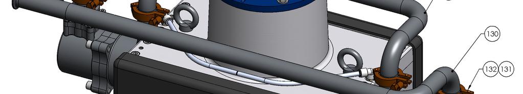
32 Maintenance Section 6.1 Assembly Procedure Final Assembly 1. Use suitable lifting equipment move the pump assembly from the bench to the floor (Note: Overall weight at this point of the assembly is 180 Kg) Using suitable rope slings around the legs, turn the pump over to stand on the legs. The pump is now in the operational orientation. 2. Lightly grease and fit the shaft bearing locknut (32). Hold the main shaft and tighten nut using special castellated tool (502508). 3. Insert the 4 off m12 X 50 Grub screws (16) into the top casting, use loctite on the threads. 4. To assist with future disassembly, Brush copperlite grease or equivalent onto the inside of the coupling half (39). Place the key (38) onto the main shaft and then slide the coupling half over the shaft and key, until firmly against the shaft shoulder. Apply Loctite 222 to the M8 clamping cap head screw and tighten to 22Nm. Fit the green spider into the coupling half. 5. Brush copperlite grease onto the gearbox shaft and key. Slide the other coupling half over the gearbox shaft and key until flush with the end of the shaft. (this is important as it ensures there is no axial preload on the spider and bearing) Apply loctite 222 and tighten the M8 clamping cap head screw to 22Nm. 6. Using suitable lifting equipment, lower the motor / gearbox assembly onto the pump assembly, ensure that the spider correctly locates into each coupling half. Fit the 4 off M12 hexagon nuts (123), plain washers (122), tighten to 40Nm. 7. Fit inlet manifold (129) to the pump with 1 1/2 sanitary clamps (132) and seals (131) to the orientation required. 8. Fit outlet manifold (130) to the pump with 1 1/2 sanitary clamps (132) and seals (131) to the orientation required. 9. Fit the 4 off cover spacers (36) over the grub screws (15) and fit O ring (37) over cover spacers. 10. Fit the covers (133) over the cover spacer and secure with M8 Security TORX screws (134) and nylon washers (135) 11. Screw in the 2 off Lifting eye bolts (35) 12. Finally fit the bellows indication arrangement:- 2 off elbow (46) 2 off hose (47) and 1 off hose plug (45) Page 32 of 40 Issue: 2.1
33 Maintenance Section General The working life and thus the expected life prior to replacement of parts within a Paint Pump are greatly affected by three main factors: - Abrasiveness of Fluid Pumped Pump Duty Cycle Fluid Pressure Output requirement The two components which are more greatly affected by the above criteria than any other components in the pump are: The Main piston Seal and the Cam Follower ; it is therefore recommended that these two items are stocked as spare parts in addition to the recommended spare parts kits. It is also a requirement of the E.U. ATEX directive (Use of Equipment in Potentially Explosive Atmospheres) that any Bearings should be replaced when they have reached 90% of their calculated operational life. The following chart is included as a helpful guide, as the working life of the Cam Follower bearings used in the Pump is greatly dependant upon the Duty Cycle and Fluid Pressure Output Requirement. Before any maintenance always switch off the pump and secure against any unintentional start up. CAM FOLLOWER REPLACEMENT CHART MOTOR Hz SETTING MONTHS 18 MONTHS 12 MONTHS WORKING PRESSURE (BAR) Page 33 of 40 Issue: 2.1
34 Maintenance Section General Maintenance Schedule Daily Inspection Weekly Check for any fluid leakage. Operation Check for any excessive mechanical noise Check for excessive fluid pressure pulsation 3 Monthly Grease Cam Follower Bearings (2 off) with grease. while the pump is running. Inject about 8 full strokes from a standard grease gun fitted with a standard collet connector. 6 Monthly Grease Linear Bearings (4 off) with grease. This has to be done with the pump stopped and isolated. Inject about 15 full pumps from a standard grease gun fitted with a Hook connector. Grease Main Shaft Bearing with grease Check Gearbox Oil Level. Inspect Cam and Cam followers for excessive wear, replace if excessive wear can be seen. Annually Every 5 Years Inspect Piston and Replace Piston Seals / Bellows / Springs. Inspect Piston & Outlet Ball Checks, replace as necessary. Inspect Linear Guide Bearing and Guide Rails for excessive wear. Replace gearbox oil (per ATEX regulations) Replace main shaft bearings. Linear Guide Bearings, Guide Rails and Cams if excessive wear can be seen. Use only (KP2N-20 DIN 51825) Grease for Cam Follower Bearing. Use only (KP2N-40 DIN 51825) Grease for Linear Guide Bearings. Do not mix the Cam Follower and Linear Guide bearings grease as this will reduce the operational life. Maintenance Section Initial Run Period Following approximately 1 month running of the pump remove the cover and grease all bearings. Remove any excess grease and any dust particles present in the cam area, (Any particles present are from the cam follower tyre, this is a normal function of the bearing bedding in with the cam surface). Page 34 of 40 Issue: 2.1
35 Maintenance Section 6.3 Gearbox / Motor Wait until the unit has cooled sufficiently after stopping and isolation. Gearbox Oil Plugs / Ventilator Remove the ventilator plug prior to removing level and/or drain plug. The gearbox is supplied factory fitted with (see chapter 1.3) oil, only top up with the same type of oil and never overfill as this may cause overheating and leakage. Check the ventilator is clean and fitted correctly. If changing the oil place a suitable container underneath the plug for draining. Note: It is recommended that the oil should be warm (40-50º C) to facilitate easier draining. After filling with fresh oil refit the ventilator, level and/or drain plugs and clean up any oil spillage. Lubrication Check the oil level every 3,000 hours or 6 months top up as necessary. Replace gearbox oil every year as per ATEX regulations. If Synthetic oil is used (USA Gearbox) the recommendation is to replace the oil every 3 years Never mix different oil types. Electric Motors Maintenance of Ex Motors - are reported by EN standard, in particular:- -The electric connections must be correctly locked to avoid resistance-increases, with consequent contact overheating. - The insulation air-distance and the surface-distance between conductors, required by the standards, must be respected. - All the screws, used to assemble the parts of the motors and of the terminal box, must be completely tightened. - The replacement of seals and of components for cable entrance would be made using spare parts, supplied from the manufacturer, in order to guarantee the original type of protection. - The Ex joint surfaces have not to be machined and it is not allowed to insert, between them, any kind of seals, not foreseen or supplied from the manufacturer. The join surfaces have just to be cleaned and, in order to avoid corrosion or water entrance. Repair procedures of the Ex motors - are reported by IEC standard. When it is not possible to make the repairs of Ex motors at the manufacturer s plant, the outside workshops, deputed to this task, must be endowed by the necessary capability, including: - Sufficient technical knowledge of these motors. - Factory equipment with tooling and facilities, suitable to make repairs. - Quality control department, for the checks and the tests, requested after repairs. - For the Ex motors the repairs of parts, directly involved on the protection against the explosion risk, must be done without any modification to the original motor design. Page 35 of 40 Issue: 2.1
36 Fault Finding Section 6.4 Symptom Possible Cause Remedy Gearbox Output shaft does not rotate, even though the motor is running. Gearbox Oil leaking from the gear unit cover from the motor flange from the gear unit flange from the output oil seal Mechanics Drive between shafts in the gear unit interrupted a) Defective gasket on gear unit cover. b) Defective gasket. c) Gear unit not ventilated. Return the unit for repair and replace gearbox a) Retighten screws on gear unit cover. b) Return gearbox c) Check vent is clean/fitted and not the transportation plug Gearbox Oil leaking from ventilator a) Unit Overfilled with oil. Check and correct the oil level Cam Followers bearing generating heat / noise Carriage does not maintain contact with cam Bearing needs lubrication a) Spring tension insufficient b) Fluid seal friction or piston movement prevented Grease bearing or replace if damage is too great Check and replace springs Check fluid section Noisy Changeover Coupling spider worn Replace green spider coupling Pump will not Prime Pump will not run Fluid Section a) Air entering the suction hose/manifold b) Worn piston seals c) Ball checks not seating correctly a) No power b) Inverter Unit or safety interlocks tripped a) Check o-rings and hose connections b) Replace piston seals c) Inspect, clean/replace balls/seats a) Check electrical supply b) Check inverter and fault conditions Pump runs but lack of pressure a) Worn piston seals b) Ball checks not seating correctly a) Replace piston seals b) Inspect, clean/replace balls/seats Paint leaking from inside cover Bellows seal failure Replace bellows seal Check Piston seal, replace as necessary Excessive Pressure Pulsation a) Ball checks not seating correctly b) Main shaft bearings worn c) Cam follower worn d) Cam direction incorrect a) Inspect, clean/replace balls/seats b) Replace bearings c) Replace bearings d) Ensure cam direction is clockwise Page 36 of 40 Issue: 2.1
37 Testing and Lubricating Section 6.5 Testing and Lubrication (Qualified personnel only) 1. Connect pump to paint system. 2. Connect electric motor to a suitable electrical supply. 3. Fit the gearbox vent plug. 4. Apply (502376) grease to linear bearings (35 strokes of a grease gun on a new bearing and 15 pumps on a bearing in current use). 5. Turn on paint system and set back pressure regulator to zero. 6. Loosen inlet cylinder vent plugs and allow the inlet air to escape from the pump. When paint starts to come out tighten the plugs back up and clean any paint spillage. 7. Turn the pump on at the local isolation mounted switch. (Important Never allow the pump to run with a closed ( valved off ) inlet or outlet connection) 8. Allow the pump to run for about 10 minutes between 60 to 80Hz to ensure any trapped air is correctly vented. Check for any leaks and mechanical noises. 9. While running at a slow speed apply (502375) grease to cam follower bearings 10. While running apply (502375) grease to main shaft bearing (40 strokes of a grease gun on a new bearing and 6 pumps on a bearing in current use) 11. Run the pump at 20 cycles/min (50 HZ) and increase the back pressure to 10 Bar and run for 1 hour. Check for any leaks and mechanical noises. Fluid Drain Down Always wear protective eyewear, gloves, clothing and respirator as recommended by the fluid and solvent manufacturer. 1. Stop the pump (turn off the electric motor); isolate the paint supply and place a suitable container underneath the hose to prevent spillage. 2. Disconnect the outlet hose and position securely into a suitable container. 3. Start the pump and run at slow speed (20Hz) for 1 minute. The pump will now have most of the paint removed; however, some material will remain within the fluid cylinders and manifolds. 4. If required to finally remove any paint from the pump, place the supply hose in a compatible solvent and run the pump until sufficiently clean. Page 37 of 40 Issue: 2.1
38 Spare Parts List - Section 7.1 Recommended Replacement Spare Parts and Kits for E2-30 and E2-40 Pumps Kit No. Part No. Description Remarks # Constant Velocity Cam # Ø100 Piston E2-30 Pump # Ø114 Piston E2-40 Pump ❶ Wet Section O Ring kit ❷ Fluid Piston Seal Kit E2-30 Pump ❷ Fluid Piston Seal Kit E2-40 Pump ❸ Bellows Replacement Kit ❹ Wet section overhaul Kit E2-30 Pump ❹ Wet section overhaul Kit E2-40 Pump ❺ Cam Follower Bearing Kit ❻ Linear Guide and Rod Kit ❼ Main Bearing Overhaul Kit # * Cam Upgrade Kit* # Auto-Lubrication Kit Cam follower Bearing Check Main Parts List for details of individual Kit Contents *Pumps before serial No will have a mark 1 constant velocity Cam fitted. If new cams are required, Cam upgrade Kit must be ordered as old Cam shape is no longer available. As the Cam is now unidirectional, the direction must be checked to ensure a clockwise motion. Page 38 of 40 Issue: 2.1
39 Accessories - Section 8.1 Accessories / Maintenance Part No. Description Remarks Smart Card V Local Isolation Box Electrical Panel for Single Pump Operation Inc Smart Card Grease Gun for Cam Follower (& Main Bearings) Collet Connector Grease Gun for Linear Bearings (300 mm Extension) Hook Connector Grease for Cam Follower (& Main Bearings) Grease for Linear Bearings Pressure Switch Sensor Manifold Pressure Sensor (4-20 ma / 0-25 Bar) Pressure feedback Sanitary Gasket Sanitary Clamp Fluid Piston Seal (PTFE) E Fluid Piston Seal (PTFE) E2-40 Special Assembly Tools Required Part No. Description of Use Remarks M8 Torx Security Screwdriver for Cover FOC with a New Pump Top Bearing Locknut Tool Bottom Bearing Locknut Tool Top Bearing Press Tool Bottom Bearing Press Tool Shaft Assembly Tool Bellows Assembly Tool Bellows Assembly Spigot Page 39 of 40 Issue: 2.1
40 Justus-von-Liebig-Straße 31, Dietzenbach. DE Tel. +49 (0) Fax. +49 (0) General info@finishingbrands.eu Ringwood Road, Bournemouth, Dorset BH11 9LH. UK Tel. +44 (0) Fax. +44 (0) General info@finishingbrands.eu , Av. des Auréats, Valence cedex. FR Téléphone : +33 (0) Télécopie: +33 (0) General info@finishingbrands.eu USA Canada Customer Service 195 Internationale Blvd. Glendale Height,IL Toll Free Customer Service and Technical Support Toll Free Facsimile Binks PCE registered office Finishing Brands Germany GmbH Justus-von-Liebig-Straße 31, Dietzenbach. Amtsgericht Offenbach HRB Page 40 of 40 Issue: 2.1
Instruction Manual. Maple 8/25 Pump. Model
 Maple 8/25 Pump Model 10 40 42 Note: Read and follow all instructions and safety precautions before using this equipment 104042 - Maple 8/25 Pump Product Description This equipment is designed for use
Instruction Manual. For. Maple 30 - Pump. Model
 For Maple 30 - Pump Model 104010 Page 2 of 28 Issue: 2.2 Index Section 1.1 General Description 1.2 Operating Principle 1.3 Specifications 1.4 Dimensions and Mounting Details 2.1 Important Safety Information
Instruction Manual. Maple 60/3 Pump. Model M2
 Maple 60/3 Pump Model 104020-M2 Page 2 of 16 Issue: 1.0 Specification Pump Ratio 3:1 Max. Air Pressure Inlet Max. Fluid Pressure Nominal Flow Volume / Cycle 7 Bar 21 Bar 1.5 Litres 0.4 US Gall Fluid Output
Instruction Manual. For. Maple 60 - Pump. Model
 For Maple 60 - Pump Model 104020 Note: Read and follow all instructions and safety precautions before using this equipment 104020 Maple 60 Pneumatic Pump Product Description This equipment is designed
Instruction Manual. For. Maple 15 - Pump. Model
 For Maple 15 - Pump Model 104009 Note: Read and follow all instructions and safety precautions before using this equipment Product Description 104009 Maple 15 Pneumatic Pump This equipment is designed
Instruction Manual. Back Pressure Regulator (Low Shear ¾ ) Bar Pilot Control
 Bar Pilot Control") Back Pressure Regulator (Low Shear ¾ ) 107757 15.0 Bar 107758 - Pilot Control Product Description This Product is designed for use with: BPR - 107757, 107758, 107748, 107749, 107750, 107754, 107755, PRV22,
Back Pressure Regulator (Low Shear ¾ ) 107757 15.0 Bar 107758 - Pilot Control Product Description This Product is designed for use with: BPR - 107757, 107758, 107748, 107749, 107750, 107754, 107755, PRV22,
Instruction Manual. For. Maple - Pneumatic Pump. Model
 For Maple - Pneumatic Pump Model 104010 Note: Read and follow all instructions and safety precautions before using this equipment 104010 Maple Pneumatic Pump Product Description This equipment is designed
E2-15 Electric Drive Pump
 Instruction Manual EN E2-15 Electric Drive Pump Model 104017 (EU Model) Model 104018 (USA Model) Model 104019 (Japan Model) IT IS THE RESPONSIBILITY OF THE EMPLOYER TO PROVIDE THIS INFORMATION TO THE OPERATOR
E4-60 Electric Drive Pump
 Instruction Manual EN E4-60 Electric Drive Pump E4-60 Electric Drive Pump Model 107070 (EU Model) Model 107072 (Non Ex Model) Model 107073 (USA Model) IT IS THE RESPONSIBILITY OF THE EMPLOYER TO PROVIDE
E2-30/40 Electric Drive Pump
 Instruction Manual EN E2-30/40 Electric Drive Pump E2-30 Electric Drive Pump E2-40 Electric Drive Pump Model 107071 (EU Model) Model 107093 (EU Model) Model 107074 (USA Model) Model 107094 (USA Model)
Instruction Manual. MX88015PU-XXX Pump
 MX88015PU-XXX Pump Page 2 of 12 Issue: 1.0 Specification Flow at 60 cycles/min Flow per cycle Feature Unit 14.4 US Gal. /min. 52.8 Litres/min. 0.24 US Gallons 0.880 Litres Recommended intermittent cycle
Instruction. Issue: 1.0
 Instruction Manual Instruction Manual MX6805PU-SMX Pump MX6812PU-SMX Pump MX6833PU-SMX Pump Page 1 of 20 Issue: 1.0 Page 2 of 20 Issue: 1.0 Flow at 60 cycles/min Flow per cycle Feature Specification Unit
DISPLACEMENT PUMP INSTRUCTIONS-PARTS LIST Rev. K. Model , Series A Model , Series B Model , Series A
 INSTRUCTIONS-PARTS LIST INSTRUCTIONS This manual contains important warnings and information. READ AND KEEP FOR REFERENCE. DISPLACEMENT PUMP 308190 Rev. K 3000 psi (210 bar) MAXIMUM WORKING PRESSURE Model
Instruction Manual. Maple 7/15 Pump. Model
 Maple 7/15 Pump Model 10 40 41 Page 2 of 16 Specification Pump Ratio 15:1 Max. Air Pressure Inlet Max. Fluid Pressure Nominal Flow Volume / Cycle 7 Bar 105 Bar 0.166 Litres 0.044 US Gall Fluid Output @
Airless Spray Gun INSTRUCTIONS DP psi (345 bar) Maximum Working Pressure
 Maximum Working Pressure") INSTRUCTIONS DP-6376 Airless Spray Gun 5000 psi (345 bar) Maximum Working Pressure INSTRUCTIONS This manual contains important warnings and information. READ AND KEEP FOR REFERENCE. Table of Contents Warnings......................................
INSTRUCTIONS DP-6376 Airless Spray Gun 5000 psi (345 bar) Maximum Working Pressure INSTRUCTIONS This manual contains important warnings and information. READ AND KEEP FOR REFERENCE. Table of Contents Warnings......................................
BINKS SMART PUMPS ADVANCED DIGITAL CONTROL CIRCULATION PUMPS
 BINKS SMART PUMPS ADVANCED DIGITAL CONTROL CIRCULATION PUMPS The Original and still the BEST PROVEN TECHNOLOGY The original and still the BEST Binks Smart Pumps are respected for their energy saving capabilities
Page 1 of 12. Part# /30/2016
 Part# 1007480-02 9/30/2016 This manual contains important information concerning the installation and operation of the gun washers listed above. Read manual thoroughly and keep for future reference. INSTRUCTIONS
SB-E ISS.05. Operation Manual AA4400A Automatic Air Assisted Airless Spray Gun
 EN SB-E-2-740 ISS.05 Operation Manual AA4400A Automatic Air Assisted Airless Spray Gun Contents Page 1 - Specification & Materials of construction... 3 2 - SAFETY WARNINGS... 4 3 - Model part numbers...
Page 1 of 19. Part# /10/2006
 Part# 1002733-01 10/10/2006 This manual contains important information concerning the installation and operation of the gun washers listed above. Read manual thoroughly and keep for future reference INSTRUCTIONS
Service Manual EN. Maple 30/ R4.5
 Service Manual EN Maple 30/3 Pump Model 000 77-335 R.5 www.carlisleft.com Product Description / Object of Declaration: Pumps - Maple, DVP, 0009, 000/LS, 006, 007, 003, 000//, 0077, 000, 003, 005, 008/9,
Operation Manual BINKS 460 Automatic Spray Gun
 SB-E-2-150 ISS.01 Operation Manual BINKS 460 Automatic Spray Gun E P 1 12 1 Operation Manual 460 Automatic Spraygun Important Read and follow all instructions and Safety Precautions before using this equipment
AIR MOTOR DRIVE
 SERVICE MANUAL EN 31-450 AIR MOTOR DRIVE 77-3140-R1.0 (9/2017) 1 / 8 In this part sheet, the words WARNING, CAUTION and NOTE are used to emphasize important safety information as follows: Hazards or unsafe
Operation Manual AA4400A Automatic Air Assisted Airless Spray Gun
 SB-E-2-740 ISS.01 Operation Manual AA4400A Automatic Air Assisted Airless Spray Gun Contents Page 1 - Specification & Materials of construction... 2 2 - SAFETY WARNINGS... 3 3 - Model part numbers... 4
OPERATION MANUAL FLG-G5-14 Transtech Gravity Spraygun
 SB-E-2-790 ISS.02 OPERATION MANUAL FLG-G5-14 Transtech Gravity Spraygun E P 1-8 E Operation Manual FLG5 Gravity Feed Spraygun Important Read and follow all instructions and Safety warnings before using
Operation Manual FLG-S5-18 Transtech Suction-feed Spray Gun
 SB--2-791 ISS.04 Operation Manual FLG-S5-18 Transtech Suction-feed Spray Gun P 2 8 Operation Manual FLG5 Suction-feed Spray Gun Important Read and follow all instructions and Safety Precautions before
Operation Manual Cobra 1 Automatic Spray Gun
 SB-E-2-CBA1 ISS.06 Operation Manual Cobra 1 Automatic Spray Gun E P 1 12 1 Operation Manual Cobra 1 Automatic Spraygun Important Read and follow all instructions and Safety Precautions before using this
Operation Manual GTi Pressure Feed Spraygun
 Operation Manual GTi Pressure Feed Spraygun SB-E-2-362-C E P 1-8 1 ITW Ltd 2000 E Operation Manual GTi Pressure Feed Spraygun Important Read and follow all instructions and Safety Precautions before using
Operation Manual FLG-G5 Transtech Gravity Spray Gun SB-E ISS.05
 Operation Manual FLG-G5 Transtech Gravity Spray Gun SB-E-2-790 ISS.05 Operation Manual FLG5 Gravity-feed Spray Gun Important Read and follow all instructions and Safety Precautions before using this equipment
SB-E-2-CBA1 ISS.13. Operation Manual Cobra 1 Automatic Spray Gun
 EN SB-E-2-CBA1 ISS.13 Operation Manual Cobra 1 Automatic Spray Gun Operation Manual Cobra 1 Automatic Spraygun Important Read and follow all instructions and Safety Precautions before using this equipment
Instructions Parts List
 Instructions Parts List : RATIO Fast Flo Pump Air operated piston transfer pump for low viscosity fluids. For professional use only. Only models that are EX certified are approved for use in European explosive
AIRMIX PUMP and LOW-PRESSURE PUMP air motor with reversing block
 INSTRUCTION MANUAL AIRMIX PUMP and LOW-PRESSURE PUMP air motor with reversing block Manual : 0306 573.002.212 Date : 12/06/03 Supersedes : 17/06/02 Modif. 1 + 4 added KREMLIN REXSON Site de Stains : 150,
SB ISS.04. Operation Manual AGMDPRO Automatic Spray Gun
 EN SB-2-991 ISS.04 Operation Manual AGMDPRO Automatic Spray Gun Table of Contents Topic Page Specification and Materials of Construction 3 EC Declaration of Conformity 3 Safety Precautions 4 Model Part
Viscount I Hydraulic Motor and Displacement Pump
 INSTRUCTIONS-PARTS LIST 308 674 INSTRUCTIONS This manual contains important warnings and information. READ AND KEEP FOR REFERENCE. Rev. C Supersedes Rev. B Viscount I Hydraulic Motor and Displacement Pump
Operation Manual GTi Pressure Feed Spraygun
 SB-E-2-362 ISS.05 Operation Manual GTi Pressure Feed Spraygun E P 1-8 Operation Manual GTi Pressure Feed Spraygun Important Read and follow all instructions and Safety Precautions before using this equipment
Fast-Flo Pump INSTRUCTIONS-PARTS LIST. Table of Contents 1:1 RATIO
 INSTRUCTIONS-PARTS LIST INSTRUCTIONS This manual contains important warnings and information. READ AND KEEP FOR REFERENCE. First choice when quality counts. 07 7 Rev. Z Supersedes W Includes Rev. Y changes
D Instructions/Parts. Siphon Feed Detail Spray Gun D
 Instructions/Parts D-5-55 Siphon Feed Detail Spray Gun FOR PRODUCT INFORMATION CALL: 1-800-742-7731 309991D Important Safety Instructions Read all warnings and instructions in this manual. Save these instructions.
T1-Titanium Non-HVLP Spray Gun
 T1-Titanium Non-HVLP Spray Gun THE SPRAY GUN PEOPLE FOR PRODUCT INFORMATION CALL: 1-800-742-7731 Important Safety Instructions Read all warnings and instructions in this manual. Save these instructions.
BINKS MODEL 460 LIGHTWEIGHT AUTOMATIC SPRAY GUN
 SERVICE MANUAL EN BINKS MODEL 460 LIGHTWEIGHT AUTOMATIC SPRAY GUN AIR FLOW ADJUSTMENT Clockwise to reduce pressure; Counterclockwise to increase pressure. 1/2" DIA. MOUNTING HOLE FLUID NEEDLE ADJUSTMENT
Spray Nozzle Adapters
 INSTRUCTIONS-PARTS LIST 306 788 INSTRUCTIONS This manual contains important warnings and information. READ AND KEEP FOR REFERENCE. First choice when quality counts. Rev. G Supersedes Rev. F DIRECTIONAL
MGFHVLP. Instructions/Parts. Mini Gravity Feed System E. Part No Includes MGFHVLP Mini Gravity Feed Spray Gun and MGC 125 Gravity Cup.
 Instructions/Parts MGFHVLP Mini Gravity Feed System FOR PRODUCT INFORMATION CALL: 1-800-742-7731 309989E For gravity feed spraying of automotive colors and clears. Ideal for touch-up and detail work. Important
BINKS SPRAY GUN EXTENSIONS
 SERVICE MANUAL EN BINKS SPRAY GUN EXTENSIONS TROPHY "C", "EA", "EB", "EN", "HC", "HCVT", "SA", "SC" & "SCMBX" SERIES TROPHY "C" SERIES EXTENSIONS TROPHY "HC" SERIES EXTENSIONS TROPHY "EA" SERIES EXTENSIONS
Operation Manual Advanced - Conventional Gravity Feed Spraygun
 SB-E-2-534 ISS.06 Operation Manual Advanced - Conventional Gravity Feed Spraygun E P 1 12 Operation Manual COMPACT Gravity Feed Spraygun Important Read and follow all instructions and Safety Precautions
Binks FRX20 FLUID SECTION
 Binks FRX20 FLUID SECTION Model: FRX20HC SPECIFICATIONS Output @ 60 cycles/min: Maximum fluid pressure: Maximum operating temperature: Displacement per cycle: Stroke length: Fluid inlet size: Fluid outlet
AGITATED LID ASSEMBLY
 SERVICE MANUAL EN 31-425 AGITATED LID ASSEMBLY 41-3312, 41-3312-S DIRECT DRIVE AGITATORS 77-1474-R20 (3/2018) 1 / 8 www.carlisleft.com AGITATOR ASSEMBLY FOR 25 Litre (5 Gal.) PAIL IMPORTANT: Read and follow
AUTOMATIC AIRSPRAY GUN
 INSTRUCTION MANUAL AUTOMATIC AIRSPRAY GUN Manual : 0407 573.011.212 Date : 19/07/04 Supersede : KREMLIN REXSON - Site de Stains : 150, avenue de Stalingrad 93 245 - STAINS CEDEX - FRANCE Téléphone : 33
Binks MODELS & AGITATOR DRIVE UNITS
 Binks MODELS 31-393 & 31-394 AGITATOR DRIVE UNITS for Agitator Equipped Drum MODEL 31-393 Includes the following items: 1, 2, and 3. 1 MODEL 31-394 shown. 17 4 3 2 12 13 14 15 2 3 8 5 9 11 8 10 6 7 17
Installation, Operation, and Maintenance Manual
 Industrial Process Installation, Operation, and Maintenance Manual Cam-Tite Ball Valve Table of Contents Table of Contents Introduction and Safety...2 Safety message levels...2 User health and safety...2
Multi-Spray Unit Air-Assisted Airless Spray Unit MSU-111N (13:1 Stand Mount) MSU-113N (13:1 Cart Mount) MSU-114N (13:1 Wall Mount)
 MSU-113N (13:1 Cart Mount) MSU-114N (13:1 Wall Mount)") Instruction Manual Multi-Spray Unit Air-Assisted Airless Spray Unit MSU-111N (13:1 Stand Mount) MSU-113N (13:1 Cart Mount) MSU-114N (13:1 Wall Mount) MSU-323N (17:1 Cart Mount) MSU-324N (17:1 Wall Mount)
Instruction Manual Multi-Spray Unit Air-Assisted Airless Spray Unit MSU-111N (13:1 Stand Mount) MSU-113N (13:1 Cart Mount) MSU-114N (13:1 Wall Mount) MSU-323N (17:1 Cart Mount) MSU-324N (17:1 Wall Mount)
50:1 Grease Pump Kits
 TM INS680A Published: 6/0/00 Revised 7/8/06 50: Grease Pump Kits Models L680A Read the following precautions and instructions before you begin assembly or using. Failure to comply with these instructions
1/2" AIR DRIVEN DIAPHRAGM PUMP
 1/2" DRIVEN DIAPHRAGM PUMP OPERATION AND SERVICE GUIDE O-1225D NOV. 2008 Page 1 of 6 Refer to Bulletin P-605, Parts List P-9151 DRIVEN, DOUBLE DIAPHRAGM PUMP MANUAL Congratulations on purchasing one of
Servicing the Tool. Service Kit SERVICE KIT. For all servicing we recommend the use of the service kit (part number (S)).
).") Servicing the Tool Service Kit For all servicing we recommend the use of the service kit (part number 07900-04750(S)). SERVICE KIT ITEM PART Nº DESCRIPTION Nº OFF ITEM PART Nº DESCRIPTION Nº OFF 07900-00002
Servicing the Tool Service Kit For all servicing we recommend the use of the service kit (part number 07900-04750(S)). SERVICE KIT ITEM PART Nº DESCRIPTION Nº OFF ITEM PART Nº DESCRIPTION Nº OFF 07900-00002
CONTENTS. VIKING PUMP, INC. A Unit of IDEX Corporation Cedar Falls, IA USA SECTION TSM 710.1
 TECHNICAL SERVICE MANUAL industrial heavy duty motor speed pumps SERIES 4076 AND 4176 SIZES hle, ate and ale SECTION TSM 710.1 PAGE 1 of 8 ISSUE B CONTENTS Introduction....................... 1 Safety
Model 550 Automatic Airless Spray Gun
 Model 550 Automatic Airless Spray Gun For Professional Use Only warning high pressure warning Maximum Working pressure Up to 3000 pounds per square inch Do not point spray gun at any part of the human
Maintenance Instructions
 General Note These instructions contain information common to more than one model of Bevel Gear Drive. To simplify reading, similar models have been grouped as follows: GROUP 1 Models 11, 0, 1,, (illustrated),,
Air Compressor. Operating & Maintenance Instructions 1110 ENGINE DRIVEN - 1 -
 Air Compressor ENGINE DRIVEN Operating & Maintenance Instructions 1110-1 - Read these safety instructions before using the equipment. INTRODUCTION Thank you for purchasing this Clarke portable compressor.
Air Operated Double Diaphragm Pump. M-Pump ½ Metallic Non Metallic Pump INSTALLATION, OPERATION & MAINTENANCE MANUAL
 Air Operated Double Diaphragm Pump M-Pump ½ Metallic Non Metallic Pump INSTALLATION, OPERATION & MAINTENANCE MANUAL 0.5 I.O.M rev 05. 12/2015 INDEX Title Section Introduction.1 Safety.2 Warranty, General
50 TONNE HYDRAULIC PRESS MODEL NO: CSA50FP
 50 TONNE HYDRAULIC PRESS MODEL NO: CSA50FP PART NO: 7615202 OPERATION & MAINTENANCE INSTRUCTIONS WARNING: Read these instructions before using the press GC0516 INTRODUCTION Thank you for purchasing this
20 TONNE HYDRAULIC PRESS MODEL NO: CSA20FBT
 20 TONNE HYDRAULIC PRESS MODEL NO: CSA20FBT PART NO: 7614058 OPERATION & MAINTENANCE INSTRUCTIONS WARNING: Read these instructions before using the press GC0516 INTRODUCTION Thank you for purchasing this
Model 570 Automatic Mastic Airless Spray Gun
 Model 570 Automatic Mastic Airless Spray Gun 6700-0000-7 For Professional Use Only warning high pressure warning Maximum working Pressure Up to 4000 pounds per square inch Do not point spray gun at any
B14 AAA FINE FINISH SERIES PUMP OUTFIT
 PRODUCT INFORMATION B14 AAA FINE FINISH SERIES PUMP OUTFIT The B14 AAA pump system is an air assisted airless unit which combines airless and conventional or HVLP air atomization technologies to produce
Lubricator Gun: 10,000 psi (700 bar) Maximum Delivery Pressure when disconnected from Dispenser
 Maximum Delivery Pressure when disconnected from Dispenser") INSTRUCTIONS-PARTS LIST 30 455 INSTRUCTIONS This manual contains important warnings and information. READ AND KEEP FOR REFERENCE. Rev. C Supercedes B Hand-Operated Portable Grease Dispenser Buckshot Luber
INSTRUCTIONS-PARTS LIST 30 455 INSTRUCTIONS This manual contains important warnings and information. READ AND KEEP FOR REFERENCE. Rev. C Supercedes B Hand-Operated Portable Grease Dispenser Buckshot Luber
herkules 338 Air Operated Diaphragm Pump
 Instructions Parts List herkules 8 Air Operated Diaphragm Pump 00 psi (0.7 MPa, 7 bar) Maximum Fluid Working Pressure 00 psi (0.7 MPa, 7 bar) Maximum Air Input Pressure 09668H Model No. 49 Acetal Pump,
USE and MAINTENANCE INSTRUCTION MANUAL AZ3 HTE2 AZ3 HTE2 HVLP GRAVITY. SPRAY GUN Series. en it fr es pt de se
 USE and MAINTENANCE INSTRUCTION MANUAL AZ3 HTE2 AZ3 HTE2 HVLP GRAVITY SPRAY GUN Series en it fr es pt de se TECHNICAL DATA Technical AZ3 HTE2 AZ3 HTE2 HVLP 1.0 80 180 1.3 10-15HTE 140 200 240 1.5 2.0 160
Pro Shot Grease Dispense Valve
 Instructions Parts List Pro Shot Grease Dispense Valve 309032J For high pressure grease dispense. 8000 psi (55 MPa, 552 bar) Maximum Working Pressure Model No. 242055, Series B, 1/4 npt Fluid Inlet Model
Air Operated Diaphragm Pumps Operating and Maintenance Instructions
 Product & Chemical Disclaimer The user must take responsibility in the selection of the products materials of construction. Empire Pumps Ltd will act in an advisory role and offer recommendations; however,
Husky 1040 Air-Operated Diaphragm Pumps
 Instructions - Parts List ACETAL, POLYPROPYLENE, AND PVDF Husky 040 Air-Operated Diaphragm Pumps 308443ZAD EN inch AODD pump for fluid transfer applications. For professional use only. Not approved to
TECHNICAL SERVICE MANUAL
 Electronic copies of the most current TSM issue can be found on the Viking Pump website at www.vikingpump.com TECHNICAL SERVICE MANUAL industrial heavy duty motor speed pumps SERIES 4076 AND 4176 SIZES
IMPORTANT SAFETY NOTICE
 IMPORTANT SAFETY NOTICE To: Our Valued Customers User safety is a major focus in the design of our products. Following the precautions outlined in this manual will minimize your risk of injury. ITT Goulds
Parker Hannifin Filtration Group Racor Division DUAL FBO OPERATION AND MAINTENANCE INSTRUCTIONS SPARE PARTS
 Parker Hannifin Filtration Group OPERATION AND MAINTENANCE INSTRUCTIONS SPARE PARTS DFBO-10-IN/DFBO-14-IN DFBO-14-MA 2(23) Duplex Fuel Filter / Separator Operation and Maintenance Instructions 73309 031912
PN9000 Series Pneumatic Actuators Installation and Maintenance Instructions
 3579049/14 IM-P357-29 CTLS Issue 14 PN9000 Series Pneumatic Actuators Installation and Maintenance Instructions PN9100 PN9200 1. Safety information 2. General product information PN9300 3. Installation
Pressure Roller with 24-inch Fixed Extension - For application of architectural paints and coatings -
 Instructions Important Safety Instructions Read all warnings and instructions in this manual. Save these instructions. 311082D Pressure Roller with 24-inch Fixed Extension - For application of architectural
HOT WASHER MODEL NO: KING 125 OPERATION & MAINTENANCE INSTRUCTIONS PART NO: LS1009
 HOT WASHER MODEL NO: KING 125 PART NO: 7320170 OPERATION & MAINTENANCE INSTRUCTIONS LS1009 INTRODUCTION Thank you for purchasing this Hot Washer. This machine is a portable, high pressure power washer,
ATTENTION! READ BEFORE ATTACHING THE AIR HOSE
 Binks SV50 HVLP GRAVITY FEED SPRAY GUN & TOUCHUP GUN ATTENTION READ BEFORE ATTACHING THE AIR HOSE HVLP AIR SUPPLY REQUIREMENTS FULL SIZE GUN: 30 PSI inlet pressure provides 10 PSI at the air cap. Consumes
Operating Manual High Viscosity Dispense Valve Item #
 Operating Manual High Viscosity Dispense Valve Item # 984594 CLOSE OPEN Item # 984594 Label # 8901197 Warnings INJECTION HAZARD Spray from the valve, hose leaks, or ruptured components can inject fluid
Instructions Parts List
 Instructions Parts List ACETAL Husky 515 Air Operated Dual Inlet Diaphragm Pump Used to evacuate and transfer fluids. 100 psi (0.7 MPa, 7 bar) Maximum Fluid Working Pressure 100 psi (0.7 MPa, 7 bar) Maximum
Swing Piston Compressors and Vacuum Pumps
 Swing Piston Compressors and Vacuum Pumps NPK 018 AC Pressure NPK 018 DC Pressure NPK 018 AC Vacuum NPK 018 DC Vacuum Operating and Installation Instructions Read and observe these Operating and Installation
Air Operated Diaphragm Pumps
 Instructions Air Operated Diaphragm Pumps 30898ZAC For fluid transfer applications. For professional use only. Only models marked with (*) are approved for use in European explosive atmosphere locations.
FLENDER ZAPEX couplings. Type ZWT. Operating instructions BA 3505 EN 10/2011. FLENDER couplings
 FLENDER ZAPEX couplings Type ZWT Operating instructions FLENDER couplings FLENDER ZAPEX couplings Type ZWT Operating instructions Translation of the original operating instructions Technical data Notes
Fast-Flo Air Motor 12.5 bar (1.25 MPa, 180 psi) Maximum Air Working Pressure
 Maximum Air Working Pressure") 03652 Instructions Parts List Fast-Flo Air Motor 12.5 bar (1.25 MPa, 180 psi) Maximum Air Working Pressure 307456S Model 215963, Series A 101.6 mm (4 in.) stroke NOTE: To replace Air Motor 215963, order
03652 Instructions Parts List Fast-Flo Air Motor 12.5 bar (1.25 MPa, 180 psi) Maximum Air Working Pressure 307456S Model 215963, Series A 101.6 mm (4 in.) stroke NOTE: To replace Air Motor 215963, order
BINKS MODEL ROVING CUTTER
 SERVICE MANUAL EN BINKS MODEL 201-510 ROVING CUTTER! WARNING Extreme caution needed when using this product. Cutters have sharp blades which are rotating at high speed. Never operate this product with
H2O-C14 AAA FINE FINISH SERIES PUMP OUTFIT
 PRODUCT INFORMATION H2O-C14 AAA FINE FINISH SERIES PUMP OUTFIT The H2O-C14 AAA pump system is an air assisted airless unit which combines airless and conventional or HVLP air atomization technologies to
PRODUCT SERVICE MANUAL FOR BK12DHZ PUMPS
 PRODUCT SERVICE MANUAL FOR BK12DHZ PUMPS WARNING This manual, and the GENERAL INSTRUCTION MANUAL SRM00046, should be read thoroughly prior to pump installation, operation or maintenance. Manual No. SRM00095
LUBRICATOR GUN INSTRUCTIONS-PARTS LIST. 10,000 psi (700 bar) Maximum Delivery Pressure. Detachable-type
 Maximum Delivery Pressure. Detachable-type") INSTRUCTIONS-PARTS LIST 306 460 INSTRUCTIONS This manual contains important warnings and information. READ AND KEEP FOR REFERENCE. Rev. E Supercedes D Detachable-type LUBRICATOR GUN 10,000 psi (700 bar)
INSTRUCTIONS-PARTS LIST 306 460 INSTRUCTIONS This manual contains important warnings and information. READ AND KEEP FOR REFERENCE. Rev. E Supercedes D Detachable-type LUBRICATOR GUN 10,000 psi (700 bar)
Instructions Parts List
 Instructions Parts List ALUMINUM AND STAINLESS STEEL Husky 040 Air-Operated Diaphragm Pumps inch AODD pump for fluid transfer applications. For professional use only. See Models on page for a list of pump
B14 AAA FINE FINISH SERIES PUMP OUTFIT
 PRODUCT INFORMATION B14 AAA FINE FINISH SERIES PUMP OUTFIT The B14 AAA pump system is an air assisted airless unit which combines airless and conventional or HVLP air atomization technologies to produce
Instruction Sheet. 1/2 HP Portable Electric Pumps SAFETY FIRST. L2062 Rev. F 02/ IMPORTANT RECEIVING INSTRUCTIONS 2.
 Instruction Sheet 1/2 HP Portable Electric Pumps L2062 Rev. F 02/12 Index: English:...................................... 1-7 Français:.................................... 8-14 Deutsch:...................................
USE and MAINTENANCE INSTRUCTION MANUAL W-300 W-300 WB LPH-300 GRAVITY. SPRAY GUN Series. en it fr es pt de se
 USE and MAINTENANCE INSTRUCTION MANUAL W-300 W-300 WB LPH-300 GRAVITY SPRAY GUN Series en it fr es pt de se TECHNICAL DATA High T.E.C. series Nozzle_Needle set Combination W-300 WB W-300 W-300-081G 0.8
Instructions Parts List
 Instructions Parts List POLYPROPYLENE AND PVDF Husky 50 Air-Operated Diaphragm Pumps 08550ZAC inch AODD pump for fluid transfer applications. For professional use only. Not approved to European explosive
Instructions - Parts List Sanitary Series FDA-Compliant Diaphragm Pumps
 Instructions - Parts List Sanitary Series FDA-Compliant Diaphragm Pumps 311879F For use in sanitary applications. Model FD1 1040 FDA Model FD 1590 FDA Model FD3 150 FDA 10 psi (0.8 MPa, 8 bar) Maximum
1100W PORTABLE GENERATOR
 1100W PORTABLE GENERATOR MODEL NO: G1200 PART NO: 8010110 OPERATION & MAINTENANCE INSTRUCTIONS LS0312 INTRODUCTION Thank you for purchasing this CLARKE 1100W Portable Generator. Before attempting to use
DENISON HYDRAULICS open loop pump controls series P140 A-mod, P260 B-mod service information
 DENISON HYDRAULICS open loop pump controls series P10 A-mod, P260 B-mod service information Publ. S1-AM02-A replaces S1-AM02 01-97 CONTENTS typical characteristics-------------------------------------------------------------------------------
LOG CHOP. Hydraulic Wood Guillotine. Owners Illustrated Instruction Book & Parts List
 LOG CHOP Hydraulic Wood Guillotine Owners Illustrated Instruction Book & Parts List Grovebury Road, Leighton Buzzard, Bedfordshire. LU7 4UX. UK. Tel:01525 375157. Fax:01525 385222. Email: enquires@brownsagricultural.co.uk
Instructions Parts List
 Instructions Parts List ALUMINUM AND STAINLESS STEEL Husky 1040 Air-Operated Diaphragm Pumps Aluminum Model Shown 120 psi (0.8 MPa, 8 bar) Maximum Fluid Working Pressure 120 psi (0.8 MPa, 8 bar) Maximum
LDG6000SA DIESEL GENERATOR OWNERS MANUAL
 LDG6000SA DIESEL GENERATOR OWNERS MANUAL BEFORE OPERATING THIS EQUIPMENT PLEASE READ THESE INSTRUCTIONS CAREFULLY Preface Thank-you for purchasing this generator. This operation manual contains information
Standard Valves Series Globe Valves Series Angle Valves Series Way-Valves
 Installation, Operation, Maintenance Instructions Standard Valves Series 035 000 Globe Valves Series 031 000 Angle Valves Series 033 000 3-Way-Valves 1 GENERAL INFORMATION These instructions are designed
INSTRUCTION MANUAL. I/P Converter DSG BXXY3Z DSG BXXY4Z
 INSTRUCTION MANUAL I/P Converter DSG BXXY3Z DSG BXXY4Z Revision 2.0 3.626 016136 en Page 1/15 Should you have any questions concerning the I/P converter, please contact the Service Department of the Product
HEAVY DUTY PNEUMATIC TORQUE WRENCH (C-RAD) USER GUIDE
 USER GUIDE") HEAVY DUTY PNEUMATIC TORQUE WRENCH (C-RAD) USER GUIDE Ref: WCOI.041 Date: June 2015 Issue: 4 Page Description CONTENTS 1 Introduction Training Requirements 2 General Safety 3 C-RAD Wrench Models Covered
HEAVY DUTY PNEUMATIC TORQUE WRENCH (C-RAD) USER GUIDE Ref: WCOI.041 Date: June 2015 Issue: 4 Page Description CONTENTS 1 Introduction Training Requirements 2 General Safety 3 C-RAD Wrench Models Covered
Operation Manual DVP 1:1 ratio Pneumatic Diaphragm Pump
 SB-E-15-DVP-H 03/2007. Operation Manual DVP 1:1 ratio Pneumatic Diaphragm Pump E P 1 13 2008 ITW Industrial Finishing Operation Manual DVP 1:1 Ratio Pneumatic Diaphragm Pump Important Read and follow all
PACKING, HANDLING, TRANSPORTING AND STORING MOTORS
 PACKING, HANDLING, TRANSPORTING AND STORING MOTORS Make sure that the shaft of the motor is not loaded in any way and is protected from knocks. Axial loads or shocks may easily damage the bearings inside
EcoPump HP Pneumatic Horizontal Piston Pump
 EcoPump HP Pneumatic Horizontal Piston Pump Operating instructions MPU00002EN, V04 www.durr.com N24160001 N24160002 N24160003 Dürr Systems GmbH Application Technology Carl-Benz-Str. 34 D-74321 Bietigheim-Bissingen