Instruction Manual for S-Stage KIT(125cc / SCUT)
|
|
|
- Wilfred Flynn
- 5 years ago
- Views:
Transcription

1 Instruction Manual for S-Stage KIT(125cc / SCUT) The ceramic-coated cylinder is used. We coated the piston with molybdenum. Item No. Applicable Models Frame Nos Ape100 HC XR100Motard HD CRF100F HE XR100R HE Thank you for purchasing one of our TAKEGAWA s products. Please strictly follow the following instructions in installing and using the products. Before fitting the products, please be sure to check the contents of the kit. Should you have any questions about the products, please kindly contact your dealer. We coated the cylinder with ceramic composite jet to improve the conventional cast-iron sleeve in durability and wear-proof. Moreover, we have reduced the friction loss and the piston clearance, and coated the piston with molybdenum to better the lubricated contact. Moreover, the bigger fins than the conventional ones help to hold down the rise in cylinder temperatures. As the bigger-finned cylinder differs from the normal one in the shape, the engine looks different, enhancing the customized image of a motorcycle. This kit includes the oil jet cylinder (Patent pending) which oil is injected from the cylinder wall directly. We strongly hope that you will use the Kit with the full knowledge and understanding of the following. Please note that, in some cases, the illustrations and photos may vary from the actual hardware. Caution about fuel to use This product is so designed to achieve a higher compression ratio than stock engines. As for the fuel, high-octane gasoline should always be used. In case regular gasoline is used, abnormal combustion takes place, and the engine cannot achieve its original performance. Moreover, it is highly likely that the piston will break down, leading to serious failure of the vehicle. Before installing, make sure that no regular gasoline remains in the fuel tank. In case regular gasoline is remaining in the fuel tank, do replace it with high-octane gasoline. Caution about spark plug Be sure to replace a spark plug with high thermal value of CR8HSA (NGK) or U24FSR-U(DENSO). Subsequently, choose and use a right spark plug with the right level, depending on the degree of burning of the spark plug electrode section. The following show the envisioned possibility of injuries to human bodies, and physical loss or damage as a result of disregarding the following cautions. We shall be held free from any kind of warranty whatsoever of products other than this product if the glitch takes place on the other products than this one after the installation and use of this product. You are kindly requested not to contact us about the combination of our products with other manufacturers. This kit is designed for exclusive use in the above-mentioned types of motorcycles and frame numbers only. Please take note that this product cannot be mounted on other types of motorcycles. Installation of this kit requires engine removal and mounting. We strongly recommend you to work strictly following HONDA genuine parts service manual for your vehicle. For installation, please prepare tools (as specified on page 2 ) and work with reference to the installation procedures with enough care. Besides, this instruction manual, as well as HONDA s genuine parts service manual, is prepared for persons who have acquired basic skills and knowledge in tuning. We recommend those who are technically inexperienced or without enough tools to ask a technically-reliable specialist shop for the installation work. On the Ape or XR100 Motard, this Kit alone does not perform well. Please separately purchase a Carburetor Kit. PD22 Carburetor Kit: Item No with a filter, Item No without a filter We would recommend our TAKEGAWA s muffler to make your engine more powerful. Some of bolts, nuts, dowel pins and packing will be reused. However, be sure to replace worn-down or severely-damaged ones with new ones. Never use liquid packing. It may plug the oil passage, and in the worst case break the engine. Installation of this product requires left side crankcase cover gaskets (HONDA s item No KN4-750), which please purchase. You may install and use this Kit together with an oil-jet-processed crankcase. And you do not have to oil-jet-process the crankcase anew. Please read the following instructions before installation.
2 CAUTION The following show the envisioned possibility of injuries to human bodies and property loss as a result of disregarding the following cautions. Work only when the engine and the muffler are cool. (Otherwise, you will burn yourself.) Prepare right tools for the work, and do the work in the proper and right way. (Otherwise, improper work could cause breakage of parts or injuries to yourself.) Always use a torque wrench to screw bolts and nuts tight and securely to the specified torque. (Improper torque could cause these parts to get damaged or fall off.) As some products and frames have sharp-pointed or protruding portions, please work with your hands protected. (Otherwise, you will suffer injuries.) Before riding, always check every section for slack in parts like screws. If you find slack ones, screw them securely up to the specified torque. (Or improper torque may cause parts to come off.) Check carefully gaskets and seals, and in case wear or damage is detected, always replace them with new ones. The following show the envisioned possibility of human death or serious injuries to human bodies as a result of disregarding the WARNINGS following cautions. Please always try to ride a motorcycle at legal speed on the public road, abiding by the law. Always drive the engine in a well-ventilated place, and do not switch the engine on in an airtight place. (Otherwise, you will suffer from carbon monoxide poisoning. ) When you notice something abnormal with your motorcycle while riding down a road, stop riding immediately and park your motorcycle in a safe place. (Otherwise, the abnormality could lead to an accident.) Before doing work, place the motorcycle on level ground to stabilize the position of your motorcycle for safety s sake. (Otherwise, your motorcycle could fall down and injure you while you are working.) Check or perform maintenance of parts correctly according to the procedures in the instruction manual or a service manual. (Improper checking or maintenance could lead to an accident.) If you find damaged parts when checking and performing maintenance, do not use these parts any longer, and replace them with new ones. (The continued use of these damaged parts as they are could lead to an accident.) Please be informed that, mainly because of improvement in performance, design changes, and cost increase, the product specifications and prices are subject to change without prior notice. This manual should be retained for future reference. About Screws Usually, counterclockwise rotation loosens the bolts and nuts, and clockwise rotation tightens them. When tightening a screw, at first tighten it by hand at tight as you can. To loosen a screw means turning a tightened screw around three or four times counterclockwise, and to unscrew it means turning it around counterclockwise until it comes off. To tighten a screw means to keep a screw from getting loose. The numeric valve as a guide at which a screw will not break or get loose when tightened is the so-called tightening torque. If you do not have a torque wrench, please try to tighten a screw as tight as possible to the level where the screw will not break or get loose, though we can not take any responsibility for the screw breakage or getting loose. In case you do not use a torque wrench, you need to judge, only by intuition or using experience, the degree of tightening power at which the screw will break or get loose. Improper use of tools will result in breakage of the top of a bolt or screw.

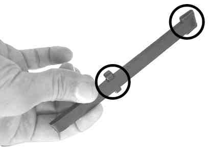
3 Kit Contents Please note that in ordering repair parts, be sure to quote the Repair Part Item No. Otherwise, we may not be able to accept your orders. There are some parts, however, for which we are not in a position to accept your order in just the quantity to be used. In this case, please take them in the quantity packed. Examples of tools for installation


4 Shut off the fuel petcock. Installation Procedures Side Cover Removal Ape100 Unscrew a bolt on the right side cover. The cover can be removed by detaching two bosses from the frame. Right side cover Bosses Exhaust Muffler Removal Take off two nuts on the cylinder head side. Remove a wire band. Stabilize the body firmly with a racing stand or the like in order to remove the side stand. Work only when the engine and the muffler are cool. Take off all dirt like the dust and oil on each part as you detach it. Bolt Don t let the removed bolts and nuts go astray, and Dismount three bosses on the left side cover from keep them orderly so you can recall where to fix the frame, then the side cover becomes detached. them. Bosses Shift the tube clip to disconnect the fuel tube. Ape Unscrew and remove mounting bolts and washers, and detach an exhaust muffler. Disconnect the wiring of the breather hose. Loosen the nut on a clutch cable guide, and disconnect a clutch cable from a lifter lever. XR100 Motard Left side cover XR100 Motard Unfasten the flange bolts on the right and left side Detach two flange bolts to remove the exhaust muffler. covers to remove the right and left side covers. Engine Removal Seat and Tank Removal Disconnect the clutch cable from the cable guide. XR100R Dismantle the engine from the frame following the instructions on the Instruction or Service Manual. Ape100 Unscrew two bolts, and remove the seat by pulling it toward the back of the vehicle. Carburetor Removal Remove a carburetor s top cap, and pull out the throttle valve from the carburetor. Spark Plug Removal Pull a plug cap to demount it. Be sure to pull the cap, not a wire. Hook Seat Drive Sprocket Removal Unscrew five bolts on the left side crankcase cover, and remove the left side crankcase cover. Loosen a screw on the connecting tube band. Remove a spark plug. Bolts Unscrew a bolt and remove the fuel tank by pulling it toward the back of the vehicle. Fuel tank Bolt Collar Unscrew two bolts, and remove a manifold and the carburetor from the cylinder head. Wiring Disconnection Disconnect the wiring. Wire band


5 If the gasket material remains on the mating surfaces, get rid of it with a cutter or a scraper. Remove a spacer in advance. Detach four nuts on a front engine hanger, take four bolts out, and remove the front engine hanger. Removal of Cylinder Head, Cylinder, and Piston Suspend the cam chain with a wire or the like to keep it from falling into the case. Cylinder Head Removal Unscrew two bolts on the cylinder head cover, and remove the cylinder head cover and its gasket. Spacer Unscrew two bolts on the drive sprocket, and remove a fixing plate and the drive sprocket. Remove a nut on the upper rear engine mount. Demount a cylinder head mounting bolt. Remove a bottom side nut also. Fix a flywheel, and loosen two hex bolts on a cam Loosen four cam shaft holder nuts in several steps sprocket. diagonally, and remove four washers, a cam shaft holder, a cam shaft, and dowel pins. Left Step Removal Remove the side stand switch cord from the frame. adjuster. First, pull out the upper side bolt and then remove a collar (Ape) and the clutch cable guide. Unfasten a lock bolt and a set plate, and remove an Set plate Lock bolt Unscrew two bolts, and remove the left step. Remove two hex bolts from the cam sprocket. Take out the bolt on the lower side, and detach the engine from the left side of the frame. Be careful not to give scratches to the frame. Engine Removal Place a jack or substitute stand under the engine to hold up the engine. Detach the cam sprocket from the cam shaft and then, from the cam chain.


 Plug the cylinder hole on the crankcase and a")


6 Remove the cylinder head. Detach two dowel pins in advance and keep them for reuse. Remove a lock nut and an adjust bolt from the cylinder. Push out the piston pin with a driver or the like in the direction where one of the two circlips has just been removed. S-Stage Kit Installation Piston Installation Fix one of kit s piston pin circlips to a pin hole. Place a circlip so its end gap does not meet with the notch on the pin hole. You can rather easily install it by pressing it into the piston with a screwdriver, but taking care not to damage the piston with a screwdriver. Do the job carefully as, in some cases, the circlip comes off flying while you press it inside. Now you can take out the piston. Mating Surface Cleaning Completely get rid of the gasket scraps on the mating surface with a cutter or a scraper. Be careful not to give scratches to the surface. Fix piston rings according to the figure below. from the cylinder. With a cutter or a scraper, get rid of the gasket scraps remaining on the cylinder head plane on which to fit a manifold. Detach a spring, and remove a cam chain tensioner Mark Top ring Wipe the surface with a waste cloth. Side rail Expander Side rail Oil ring Cylinder Removal Fix the oil ring expander. Remove the cam chain guide, and pull out the cylinder. (If it is hard to pull it out, hit the cylinder lightly with a plastic hammer.) Plug the cylinder hole on the crankcase and a cam chain hole with a waste cloth or clean rag not to let any dirt or part fall into the hose. Cam chain guide Put the top and bottom oil ring side rails. Take off two dowel pins in advance and keep them for reuse. Piston Removal Remove one of the two piston pin circlips. You can remove it by prising it open with a screwdriver with its tip on the notch. Fix the top ring, turning up the side with an engraved letter R. Piston pin circlip Piston


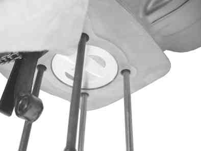
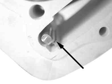
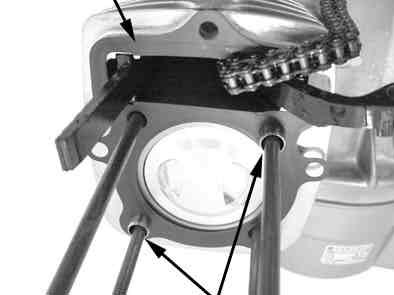
7 Apply engine oil to the piston pin hole. Cylinder Installation Insert the cam chain tensionner into kit s cylinder, and hang the hook of the spring on the cylinder. Attach two dowel pins and a cylinder gasket to the Insert the cylinder, fitting the end of a cam chain crankcase. guide into grooves in the crankcase and the protrusion into grooves in the cylinder. Protrusion Top end Apply engine oil to a piston pin hole in the con rod. Hook Apply engine oil to the inside of the cylinder and spread it with fingers to be equally applied all over. Cam chain guide Cylinder Crankcase Apply engine oil to the piston pin and place the piston in a position so the mark on the upper side of the piston faces the front or exhaust side. Place the cam chain tensioner in a position so the end of the rod will be nearly on the same level as the clamp face. Fix it with an adjust bolt and tighten the lock nut. Apply engine oil to whole surface of the piston, and the piston rings. Cylinder Head Installation Degrease the mating surfaces of the cylinder and the cylinder head with thinner or the like. Let the cylinder in. Fix the other piston pin circlip, included in the kit, to the pin hole. Place the circlip in a position so the end-gaps of a piston pin circlip do not meet with the notch on the hole. It is relatively easier to press it by a driver with care not to give scratches to the piston. Do the job carefully as, in some cases, the piston pin circlip may come off flying while you press it inside. Remove the waste cloth. Degrease the mating surfaces of the crankcase and the cylinder with thinner or the like. Insert the piston into the cylinder gradually by hand with care not to shift the piston ring s end gaps out of the position. Attach two dowel pins and a cylinder head gasket to the cylinder. Cylinder head gasket Dowel pins Pass the cam chain through the cylinder head and install the cylinder head to the cylinder. When the piston is completely in the cylinder, pass the cam chain through the cylinder and install the cylinder to the crankcase. Install an adjuster, passing it through the cam chain tensioner and the cylinder head.


 In case of there is no interference, continue the installation work.")


8 Temporarily attach a set plate with a lock bolt. After shaving, check for any burr, and clean up the Install the cam chain in the position so the O mark on cam shaftholder. the cam sprocket is right at the top. Fit the cam sprocket Apply engine oil to the journals and cams of a kit s cam into the cam shaft. shaft. And install the cam shaft to the cylinder head with the cam s top faces downward. Cam Rotate the flywheel a little by hand. Depending on how tensely or loosely the camchain is stretched to the camsprocket, turn the flywheel in either direction to get the proper tension of the camchain, watching the O mark on the adjuster. Temporarily tighten the cylinder head mountiong bolts. Installation of Cam Shaft and Cam Sprocket Journal Attach two dowel pins. Dowel pins Install the cam shaft holder. Rotate the flywheel a little, and then rotate the cam sprocket to mark it easy to install hex bolts. Align cam shaft s bolt-holes with the cam sprocket. Then attach two hex bolts to the holes by hand temporarily. At this point, attach and tighten a dowel bolt (black) to the intake side. Adjuster Set plate Lock bolt Loosen Standard position Tighten Tighten the lock bolt fully when the cam chain is found stretched properly and you can move the flywheel without difficulty, and fix the adjuster. Torque: 10 Nm (1.0 kgfm) Check the Cam shaft and the cam shaft holder for the interference. (We have arranged the lift of cam shaft in the kit to be larger than that of the stock one. the cam shaft and the cam shaft holder may interfere with each other because of the size difference among the cam shaft holders. So, please do check for the interference without fail.) Try to fit kit s cam shaft in the cam shaft holder, and check for intereference of the cam top and the holder. Fix four washers. O mark Black bolt Fix the flywheel and fully tighten the hex bolts on the cam sprocket. Torque: 12 Nm (1.2 kgfm) In case you can not get the proper tension of the camchain only by adjusting the adjuster, then adjust the tension with the adjust bolt on the cylinder. Fix the adjuster where it has the best tension. Then loosen a lock nut on the cylinder, and loosen the adjust bolt a little bit. Install and diagonally tighten four nuts equally in a few steps. Torque: 20Nm (2.0 kgfm) In case of there is no interference, continue the installation work. If there is interference, shave off the interfering parts on the cam shaft holder so it is free of the interference. Fully tighten the cylinder head mounting bolts. Torque: 12 Nm (1.2 kgfm) Cam Chain Adjustment A camchain, whether tightly or loosely streteched, will impair the engine conditions. Perform this procedure correctly. Rotate the flywheel till both cam tops of the cam shaft point up. Fix the adjust bolt with a flat tip screwdriver, and tighten the lock nut. Torque: 12 Nm (1.2 kgfm) Again, move the adjuster and hold it where the camchain has no slackness and you do not feel it hard to rotate the flywheel. Then tighten the lock bolt to fix the adjuster. CAUTION : Do not shave off more than needed. CAUTION : Work with great care not to give scratches to the cam shaft holder s journal, and clamp faces for the rocker arm and the cylinder head. Check that T mark on the flywheel is aligned with the mark on the crankcase. Alignment mark Cam tops should point this way. Valve Clearance Adjustment Rotate the flywheel counterclockwise, and stop rotating it where the O mark on the cam sprocket is on the top and the T mark on the flywheel is aligned with the mark on the crankcase. Insert a 0.05mm thickness gauge between the adjust screw and the end face of the valve (or, valve clearance). T mark
 Installation of Left Side Crankcase Degrease the clamp faces of the left side crankcase cover and the crankcase with thinner or the like.")


 Fix the drive sprocket with the drive chain to the counter shaft. If it is hard to fix the drive sprocket, fix it while shaking the engine lightly.")
 Spark Plug Installation At first, screw the spark plug by hand. Then tighten it with a plug wrench. Torque: 14 Nm (1.")


 for front engine hangar plate nut : 26 Nm (2.")
9 Adjust the position of the adjust screw so that Temporarily tighten the two nuts. there is a little resistance to pulling the gauge out. Then tighten the nut. Torque: 10 Nm (1.0 kgfm) Installation of Left Side Crankcase Degrease the clamp faces of the left side crankcase cover and the crankcase with thinner or the like. Attach a spacer, and install the left crankcase cover and a new gasket to the crankcase by tightening five bolts. Torque: 12 Nm (1.2 kgfm) Connect the breather hose. After tightening the nut, double check the valve clearance with the 0.05mm thickness gauge. Pour fresh engine oil to a oil pool on the cylinder head to the brim. Attach a front engine hanger, and insert four bolts from the left side and temporarily tighten four nuts. Attach the clutch cable to the lifter lever and install it to the clutch cable guide. Then tighten the nut. Spacer Install the cylinder head cover and its gasket to the cylinder head by tightening two cylinder head cover bolts. Torque: 12 Nm (1.2 kgfm) Fix the drive sprocket with the drive chain to the counter shaft. If it is hard to fix the drive sprocket, fix it while shaking the engine lightly. Installation of Left Side Step (for Ape) Install the left side step to the frame with two bolts. Torque: 26 Nm (2.7 kgfm) Spark Plug Installation At first, screw the spark plug by hand. Then tighten it with a plug wrench. Torque: 14 Nm (1.4 kgfm) Engine Mounting Engine Mounting XR100 R In accordance with the instructions in the Owner s Fix the side stand switch cord on the clamp of the Manual and Service Manual, mount the engine frame. onto the frame. Stretching the drive chain moderately loosely, fully Place a jack or a proper stand under the engine to tighten the two nuts on the rear engine mount and the support the engine. Then mount the engine from four nuts on the front engine hanger plate. Fix a plug cap. the left side of the vehicle. Insert a bolt into the lower part of the rear engine mount from the left side. Torque: for rear engine mount nuts : 44 Nm (4.5 kgfm) for front engine hangar plate nut : 26 Nm (2.7 kgfm) Fit the fixing plate into the counter shaft to align with the threaded holes on the drive sprocket, and fix two bolts. Torque: 10 Nm (1.0 kgfm) Wiring Connect the wiring. Attach a collar and a clutch cable guide, and insert a bolt into the upper part of the rear engine mount. Exhaust Muffler Installation XR100R In accordance with the instructions in the Owner' Manual and Service Manual, mount the engine onto the frame. XR100 Motard Fix the cords with a wire band. Install the exhaust muffler to the vehicle. Temporarily tighten two nuts on the cylinder head side. Wire band
 Bolt Fuel tank Collar Engine Starting After checking that the ignition key and the fuel cock are turned OFF, remove the spark plug.")
10 Ape100 Temporarily tighten two mounting bolts and washers. Installation of Seat and Tank Ape100 Install the fuel tank to the frame with the bolt. Torque: 26Nm (2.7 kgfm) Bolt Fuel tank Collar Engine Starting After checking that the ignition key and the fuel cock are turned OFF, remove the spark plug. Kick the starter for a while to circulate the engine oil all aroud the engine. Install the spark plug, turn on the gasoline cock and ignition key, and start the engine. CAUTION : Be sure to tighten to the specified torque. WARNING: Work in a well-ventirated area. Loosely install two flange bolts for now. XR100 Motard Fit the hook in the front on the back side of the seat into the frame and fix it by tightening two bolts. Torque: 26Nm (2.7 kgfm) Check for any abnormarity such as abnormal noises. If no problem is detected, do running-in at leaset 100 to 150 km. After the initial running-in, check for abnormality such as abnormal noises or blow-bye. (If there is a problem, disassemble the engine again to check each part.) WARNING: Do not re-use piston pin circlips. Fully tighten them. Torque: for two nuts: 12 Nm (1.2 kgfm) for mounting bolts: 20 Nm (2.0 kgfm) Hook Seat Caution Even bolts and nuts tightened to the specified torque may get loose by repeated heat expantion through warm-up at the time of engine assembly. Retighten bolts and nuts periodically. CAUTION: Be sure to tighten to the specified torque. Cautions Before Running Carburetor Installation Ape / XR100 Motard This kit will not display its potential high performance when used with a stock carburetor. Please purchase separately a Carburetor Kit. For the installation, please refer to the Instruction Manual of the Carburetor Kit. XR100R For the installation of the carburetor, please refer to the Instruction or Service Manual of the Carburetor. Side Cover Installation (In the case of the Ape) (In the case of using a stock air cleaner box) Fix the left side cover by fitting three bosses on this cover into the frame. Bosses XR100 Motard Bolts Fuel Hose Connection About fuel Always replace the gasoline with high-octane gasoline when regular gasoline is remaining in the fuel tank. Sprocket Install the right and left side covers and tighten the Adjust the sprockets depending on how you ride your vehicle. flange bolt to the specified torque. However, setting in too low gears will result in severe wears of parts, not Torque: 8Nm (0.8 kgfm) only adversely affecting the engine life, but also breaking the engine in the worst case. Please drive your vehicle at proper setting. Other notes Oil Cooler The installation of this Kit increases the heat release value of the engine, set off by the increase in power. Therefore, we recommend that you equip your machine with an Oil Cooler Kit (4-fin 5-oil line: , 3-fin 4-oil line: ) for long-hour, high-load driving. Cam Chain Connect the fuel tube with the fuel petcock, and fix it We recommend you to install our TAKEGAWA s solid cam chain, and with a tube clip. die-hard ( ) to cope with the increase in power and in heat release value of the engine. Left side cover Fit two bosses on the right side cover into the frame, and fix the bolt. Right side cover Bosses Thermometer A stick-type temperature sensor is installable on the cylinder side of this kit. TAKEGAWA s meters listed below are available. Medium LCD tachometer & thermometer: (up to 150 ) Bolt Nishikiorihigashi Tondabayashi Osaka Japan TEL : FAX : URL : Co.,Ltd.
Instruction Manual for 136cc SCUT Cylinder Kit
 Instruction Manual for 136cc SCUT Cylinder Kit Item No. Fitting Ape100, XR100 Motard, CRF100F, XR100R But limited tobikes fitted with TAKEGAWA s Super Head Thank you for purchasing one of our TAKEGAWA's
146cc SCUT Cylinder Kit Instruction Manual
 146cc SCUT Cylinder Kit Instruction Manual JP PAT. US PAT. The ceramic-coated cylinder is used. Item No. (Cylinder Kit) (Piston Kit) Fitting Ape100, XR100 Motard, CRF100F, XR100R But limited tobikes fitted
Instruction Manual for Super Head ST-1 & ST-2 CYLINDER KIT
 Instruction Manual for Super Head ST-1 & ST-2 CYLINDER KIT Item No. Fitting Ape, Ape100, XR50 Motard, and XR100 Motard SpecificationCompatible with a motorcycle equipped with a TAKEGAWA s ST-1 / ST-2 Super
Magnesium Clutch Cover Kit Instruction Manual
 Magnesium Clutch Cover Kit Instruction Manual Item No. (Brown) Applied to Ape50 Ape50 (FI) Ape50 (FI Type D) AC18-1000001 Ape100 Ape100 Type D XR50 Motard XR100 Motard Frame Nos AC16-1000001 AC16-1600001
Please read the following before installation. Points to notice about sounds
 Instruction Manual for / SCUT Cylinder Kit Thank you for purchasing one of Takegawa s products. This is a piston and cylinder kit for exclusive use in Super Head+R of Takegawa s make. You are kindly requested
Aluminium Clutch Cover Kit Instruction Manual
 Aluminium Clutch Cover Kit Instruction Manual Item No. Applied to Ape50 Ape50 (FI) Ape50 (FI Type D) AC18-1000001 Ape100 Ape100 Type D XR50 Motard XR100 Motard Frame No. AC16-1000001 AC16-1600001 HC07-1000001
Instruction Manual for DOHC 4-VALVE HEAD PISTON / CYLINDER KIT
 Instruction Manual for DOHC 4-VALVE HEAD PISTON / CYLINDER KIT Thank you for purchasing one of our TAKEGAWA s products. These piston and cylinder kits are for exclusive use in a motorcycle equipped with
Instruction Manual for S-Stage+D KIT (106cc / SCUT / Decompression)
") Thank you for purchasing one of our TAKEGAWA-made products. Please strictly follow the following instructions in installing and using the kit. Before installing the kit, please be sure to check the kit
Thank you for purchasing one of our TAKEGAWA-made products. Please strictly follow the following instructions in installing and using the kit. Before installing the kit, please be sure to check the kit
Kit Instruction Manual
 Kit Instruction Manual Thank you for purchasing one of our products. Please strictly follow the instruction to install and use the products. Before fitting the products, please be sure to check the contents
Instruction Manual for 4-Speed Close Gear Ratio Transmission Kit for XR / CRF50
 Instruction Manual for 4-Speed Close Gear Ratio Transmission Kit for XR / CRF50 Thank you for purchasing one of our TAKEGAWA s products. Please strictly follow the following instructions in installing
Dry-Type Clutch Kit Instruction Manual (Cable-type)
") Dry-Type Clutch Kit Instruction Manual (Cable-type) Item No. Applicable models and frame No.: Monkey Gorilla (6V) Z50J-13000171805927 Monkey (12V) Monkey (FI) Gorilla (12V) Monkey BAJA Monkey RT Z50J-2000001
Dry-Type Clutch Kit Instruction Manual (Cable-type) Item No. Applicable models and frame No.: Monkey Gorilla (6V) Z50J-13000171805927 Monkey (12V) Monkey (FI) Gorilla (12V) Monkey BAJA Monkey RT Z50J-2000001
Cylinder Kit (124cc) Instruction Manual
 Instruction Manual") Cylinder Kit (124cc) Instruction Manual The ceramic-coated cylinder is used. (HA Cylinder) We coated the piston with molybdenum. Thank you for purchasing one of our products. These piston and cylinder
Cylinder Kit (124cc) Instruction Manual The ceramic-coated cylinder is used. (HA Cylinder) We coated the piston with molybdenum. Thank you for purchasing one of our products. These piston and cylinder
Instruction Manual for CRF150F Hyper S-Stage Kit
 Instruction Manual for CRF150F Hyper S-Stage Kit Thank you for purchasing one of TAKEGAWA's products. Please strictly follow the following instructions in installing and using the products. Before fitting
MIKUNI VM26 Carburetor Kit Instruction Manual
 MIKUNI VM26 Carburetor Kit Instruction Manual (For exclusive use in the Super Head 4VALVE+R-equipped motorcycle) Item No. (Carburetor set) AKEGAWA-made products. Please strictly follow the following instructions
Instruction Manual for
 Instruction Manual for Thank you for purchasing one of our TAKEGAWA-made products. Please strictly follow the following instructions in installing and using the kit. Before installing the kit, please be
Special Crankcase set for Complete engine (4SMS)
") Special Crankcase set for Complete engine (4SMS) (Takegawa original stud pattern) (For 123cc only) (For 138cc only) (For SCUT 148cc only) Thank you for purchasing one of our products. This crankcase set
Special Crankcase set for Complete engine (4SMS) (Takegawa original stud pattern) (For 123cc only) (For 138cc only) (For SCUT 148cc only) Thank you for purchasing one of our products. This crankcase set
Instruction Manual Speed meter Kit for XR50 / XR100 Motard
 Thank you for purchasing one of our TAKEGAWA-made products. Please strictly follow the following instructions in installing and using the kit. Before installing the kit, please be sure to check the kit
Instruction Manual for TAF 5-Speed Transmission Kit
 Instruction Manual for TAF 5-Speed Transmission Kit (For Dry type clutch ONLY) Thank you for purchasing one of our TAKEGAWA products. Please strictly follow the instructions to install and use the kit.
TAF 5-Speed Transmission Kit Instruction Manual
 TAF 5-Speed Transmission Kit Instruction Manual Item No. Super Touring Super Street Fits Monkey and Gorilla Frame Nos Z50J-13000172699999 AB27-10000011899999 Thank you for purchasing one of our products.
TAF 5-Speed Transmission Kit Instruction Manual
 TAF 5-Speed Transmission Kit Instruction Manual Item No. Thank you for purchasing one of our TAKEGAWA's products. Please strictly follow the following instructions in installing and using the Kit. Before
Instruction Manual for Black-Panel Speed Meter & Electric Tachometer
 Instruction Manual for lack-panel Speed Meter & Electric Tachometer (for 27 front fork) Thank you for purchasing one of our TAKEGAWA s products. Please read this instruction manual carefully to have a
Kit Instruction Manual
 Kit Instruction Manual Item No. Applicable models and frame Nos Monkey Z50J-2000001 AB27-1000001 Gorilla Z50J-2500001 AB27-1000001 Thank you for purchasing one of our TAKEGAWA's products. Please strictly
Instruction Manual for FI Controller
 Instruction Manual for FI Controller Thank you for purchasing one of our TAKEGAWA s products. Please strictly follow the instructions to install and use the products. Before installing the products, please
Instruction Manual for FI Controller For Monkey (FI), Super Cub (FI), Little Cub (FI)
, Super Cub (FI), Little Cub (FI)") Instruction Manual for FI Controller For Monkey (FI), Super Cub (FI), Little Cub (FI) Item No. Fits & Frame Nos Monkey (FI)AB27-1900001 Super cub (FI)AA01-1700001 Little cub (FI)AA01-4000001 Thank you
Instruction Manual for FI Controller For Monkey (FI), Super Cub (FI), Little Cub (FI) Item No. Fits & Frame Nos Monkey (FI)AB27-1900001 Super cub (FI)AA01-1700001 Little cub (FI)AA01-4000001 Thank you
HKS 700E. Service Manual June Ver. 2.04
 HKS 700E Service Manual 009 June Ver..04 HKS CO.,LTD 78 KITAYAMA FUJINOMIYA SHIZUOKA JAPAN 48-09 TEL +8(0)544-54-78 FAX +8(0)544-54-40 hks_aviation@hks-power.co.jp http://www.hks-power.co.jp/hks_aviation/
2012 Kia Soul L4 2.0L
 2012 Kia Soul L4 2.0L Vehicle» Engine, Cooling and Exhaust» Engine» Timing Chain» Service and Repair» Repair Procedures» Part 1 Removal Engine removal is not required for this procedure. CAUTION: Use fender
13. CRANKCASE/CRANKSHAFT/BALANCER/PISTON/CYLINDER
 13. CRANKCASE/CRANKSHAFT/BALANCER/PISTON/CYLINDER COMPONENT LOCATION 13-2 SERVICE INFORMATION 13-3 TROUBLESHOOTING 13-4 CRANKCASE SEPARATION 13-5 CRANKSHAFT 13-7 MAIN JOURNAL BEARING 13-9 CRANKPIN BEARING
WORKSHOP MANUAL. Chainsaw GS35 GS350 MT350 MT3500
 WORKSHOP MANUAL Chainsaw GS35 GS350 MT350 MT3500 General failures analysis Suggested tools I. Emak tool kit II. Compression tester: to check thermal group III. Electronic tachometer: for 2 and 4 stroke
Engine Complete KIT : Spec.SUPER HEAD + R
 Engine Complete KIT : Spec.SUPER HEAD + R (4SM-148) Secondary kick starter engine SUPER HEAD + R -148 5-Speed (Super street) O / P Item No. Compatible models Monkey / GorillaZ50J -2000001 AB27-10000011899999
7. CYLINDER HEAD/VALVES
 7 7 7-0 SERVICE INFORMATION...7-1 CYLINDER HEAD DISASSEMBLY...7-7 TROUBLESHOOTING...7-2 CYLINDER HEAD ASSEMBLY...7-8 CAMSHAFT REMOVAL...7-3 CYLINDER HEAD INSTALLATION...7-8 CYLINDER HEAD REMOVAL...7-5
2012 Kia Soul L4 2.0L
 2012 Kia Soul L4 2.0L Vehicle» Engine, Cooling and Exhaust» Engine» Timing Chain» Service and Repair» Repair Procedures» Part 2 Installation 1. The TDC marks of the intake and exhaust CVVT sprockets are
SE120R SCREAMIN' EAGLE PRO RACE-USE CRATE ENGINE
 -J007 REV. 00-09-08 SE0R SCREAMIN' EAGLE PRO RACE-USE CRATE ENGINE GENERAL Kit Number 90- Models For model fitment information, see the P&A Retail Catalog or the Parts and Accessories section of www.harley-davidson.com
Engine Complete KIT : Spec.SUPER HEAD + R
 Engine Complete KIT : Spec.SUPER HEAD + R (CSM-148) Primary kick starter SUPER HEAD + R -148 5-Speed (Super street) O / P Item No. Compatible models Monkey / GorillaZ50J -2000001 AB27-10000011899999 Thank
WORKSHOP MANUAL. 63,4 cm³ chainsaws
 WORKSHOP MANUAL General failures analysis Suggested tools I. Emak tool kit II. Compression tester: to check thermal group III. Electronic tachometer: for 2 and 4 stroke engines, measurement range from
<4D5> ENGINE Click on the applicable bookmark to selected the required model year
 ENGINE 11B-2 ENGINE General Information GENERAL INFORMATION 11100010339 Items 4D56 Total displacement m 2,477 Bore x Stroke mm 91.1 x 95.0 Compression ratio 21 Combustion chamber Camshaft
CHASSIS CONTENTS EXTERIOR PARTS 7-1 FRONT WHEEL 7-2 FRONT BRAKE 7-6 HANDLEBARS 7-13 FRONT FORK 7-15 STEERING 7-23 REAR WHEEL 7-26 REAR BRAKE 7-30
 CHASSIS CONTENTS EXTERIOR PARTS 7- FRONT WHEEL 7-2 FRONT BRAKE 7-6 HANDLEBARS 7-3 FRONT FORK 7-5 STEERING 7-23 REAR WHEEL 7-26 REAR BRAKE 7-30 REAR SHOCK ABSORBER 7-32 SWING ARM 7-33 7 7- CHASSIS EXTERIOR
CHASSIS CONTENTS EXTERIOR PARTS 6-1 FRAME COVER 6-2 REAR FRAME COVER 6-4 FRONT WHEEL 6-6 FRONT BRAKE 6-10 HANDLEBARS 6-17 FRONT FORK 6-19
 CHASSIS CONTENTS EXTERIOR PARTS 6- FRAME COVER 6- REAR FRAME COVER 6-4 FRONT WHEEL 6-6 FRONT BRAKE 6-0 HANDLEBARS 6-7 FRONT FORK 6-9 STEERING 6-6 REAR WHEEL 6-3 REAR BRAKE 6-39 6 REAR SHOCK ABSORBER 6-43
7. FUEL SYSTEM ('04 - '05)
") 7. FUEL SYSTEM ('04 - '05) SYSTEM COMPONENTS 7-2 CARBURETOR DISASSEMBLY 7-81 SERVICE INFORMATION 7-3 CARBURETOR ASSEMBLY 7-14 TROUBLESHOOTING 7-4 CARBURETOR INSTALLATION 7-21 AIR CLEANER HOUSING 7-5 PILOT
7. FUEL SYSTEM ('04 - '05) SYSTEM COMPONENTS 7-2 CARBURETOR DISASSEMBLY 7-81 SERVICE INFORMATION 7-3 CARBURETOR ASSEMBLY 7-14 TROUBLESHOOTING 7-4 CARBURETOR INSTALLATION 7-21 AIR CLEANER HOUSING 7-5 PILOT
Engine Complete KIT : Spec.SUPER HEAD 4VALVE + R
 Engine Complete KIT : Spec.SUPER HEAD 4VALVE + R (4SM-123) Secondary kick starter engine SUPER HEAD 4VALVE + R -123 5-Speed (Super street) O / P Item No. Compatible models Monkey / GorillaZ50J -2000001
ENGINE MECHANICAL EM SECTION CONTENTS
 ENGINE MECHANICAL EM SECTION CONTENTS INTAKE MANIFOLD...EM-2 Component Parts Location...EM-2 Removal and Installation...EM-3 Inspection...EM-3 EXHAUST MANIFOLD...EM-4 Component Parts Location...EM-4 Removal
BR-250 / BR-250SS / M2-250 SERVICE MANUAL
 BR-250 / BR-250SS / M2-250 SERVICE MANUAL Manufactured by PGO of Motive Power Industry Co., Ltd 1. INSPECTION/ADJUSTMENT 1 1 INSPECTION/ADJUSTMENT SERVICE INFORMATION -------------------------------------------------
HSR Carburetor Sportster & Buell. Installation Manual. Revised 7/5/00
 HSR Carburetor Sportster & Buell Installation Manual Carb Kit# 42-10 Carb Kit# 42-11 94 - present Sportster All Buells Revised 7/5/00 SB-1 Sportster/Buell Installation The HSR series carburetors are precise
1. Remove the crankshaft pulley, engine coolant pump pulley and drive belt. 2. Remove the timing belt cover.
 DISASSEMBLY 1. Remove the crankshaft pulley, engine coolant pump pulley and drive belt. 2. Remove the timing belt cover. 3. Turn the crankshaft clockwise and align the timing marks so as to bring the No.
Backwater Performance Systems Large Vanguard Mikuni Twin Carburetor Kit
 Backwater Performance Systems Large Vanguard Mikuni Twin Carburetor Kit 1. Throttle Cable Twin (CKC-41) 2. Carburetor VM30mm (CKC-40) 3. Loctite 242.5mL (A-210) 4. Air Cleaner Filter 6000 (EC-86) 5. Rev
ENGINE OVERHAUL <2.4L ENGINE>
 11D-1 GROUP 11D ENGINE OVERHAUL CONTENTS GENERAL SPECIFICATIONS 11D-2 SERVICE SPECIFICATIONS 11D-2 REWORK DIMENSIONS 11D-3 TORQUE SPECIFICATIONS 11D-4 SEALANTS 11D-7 SPECIAL TOOLS 11D-8 GENERATOR
AIR CLEANER RACE KITS
 Kit Numbers 91421-99Y, 91420-99Y and 91422-99Y REV. 10-26-00 General These Air Cleaner Race Kits are intended for highperformance racing (OFF ROAD USE) applications only. Use of these kits may reduce or
9-8 LEFT CRANKCASE COVER INSTALLATION ALTERNATORETARTER A TORIST ARTER CLUTCH. Install the dowel pin and a new gasket.
 ALTERNATORETARTER A TORIST ARTER CLUTCH LEFT CRANKCASE COVER INSTALLATION Install the dowel pin and a new gasket. Install the left crankcase cover. Install the washer and bolts, and tighten them securely.
1. GENERAL INFORMATION
 GENERAL INFORMATION ENGINE SERIAL NUMBER ---------------------------------------------- - SPECIFICATIONS ---------------------------------------------------------- - 2 SERVICE PRECAUTIONS ------------------------------------------------
ENGINE OVERHAUL GROUP 11B 11B-1 CONTENTS GENERAL SPECIFICATIONS... 11B-2 OIL PAN AND TIMING CHAIN CASE... 11B-27 SERVICE SPECIFICATIONS...
 11B-1 GROUP 11B CONTENTS GENERAL SPECIFICATIONS 11B-2 SERVICE SPECIFICATIONS 11B-2 FASTENER TIGHTENING SPECIFICATIONS 11B-4 SEALANTS AND ADHESIVES 11B-7 SPECIAL TOOLS 11B-8 GENERATOR AND IGNITION SYSTEM
3. INSPECTION/ADJUSTMENT
 SERVICE INFORMATION...3-0 FINAL REDUCTION GEAR OIL...3-7 MAINTENANCE SCHEDULE...3-2 DRIVE BELT...3-7 FUEL FILTER...3-3 BRAKE SHOE...3-8 THROTTLE OPERATION...3-3 BRAKE ADJUSTING NUT...3-8 AIR CLEANER...3-4
VALCON PLUS V-CAM SYSTEM STEP 1 INSTRUCTION MANUAL
 VALCON PLUS V-CAM SYSTEM STEP 1 INSTRUCTION MANUAL NAME OF PRODUCT USE RB26 V-CAM SYSTEM STEP1 AUTOMOBILE PARTS PART NUMBER 22007-AN002 TYPE A MAKE ENGINE YEAR REMARKS 22007-AN003 TYPE B NISSAN SKYLINE
ENGINE TUNE-UP INSPECTION OF ENGINE COOLANT INSPECTION OF ENGINE OIL INSPECTION OF BATTERY. INSPECTION OF AIR FILTER (Paper Filter Type)
") ENGINE MECHANICAL - Engine Tune-Up EM-17 ENGINE TUNE-UP INSPECTION OF ENGINE COOLANT (See steps 1 and 2 on page CO-4) INSPECTION OF ENGINE OIL (See steps 1 and 2 on page LU-5) INSPECTION OF BATTERY (See
ENGINE MECHANICAL - Engine Tune-Up EM-17 ENGINE TUNE-UP INSPECTION OF ENGINE COOLANT (See steps 1 and 2 on page CO-4) INSPECTION OF ENGINE OIL (See steps 1 and 2 on page LU-5) INSPECTION OF BATTERY (See
ENGINE OVERHAUL <2.4L ENGINE>
 11B-1 GROUP 11B ENGINE OVERHAUL CONTENTS GENERAL SPECIFICATIONS 11B-2 SERVICE SPECIFICATIONS 11B-2 REWORK DIMENSIONS 11B-3 TORQUE SPECIFICATIONS 11B-4 SEALANTS 11B-7 SPECIAL TOOLS 11B-8 GENERATOR
1.CONTENTS 1. Contents Control location Before riding Safe riding Driving Use genuine spare parts Use
 1.CONTENTS 1. Contents... 1 2. Control location... 3 3. Before riding... 4 4. Safe riding... 4 5. Driving... 5 6. Use genuine spare parts... 5 7. Use of each component... 6 Gauges... 6 Operation of ignition
OVERHAULING THE ENGINE. 85 Nm (8.5 m kg, 61 ft Ib) Order Job/Part Q ty Remarks Removing the drive sprocket
 Order Job/Part Q ty Remarks Removing the drive sprocket") INE EAS00188 INE DRIVE SPROCKET OVERHAULING THE INE 10 Nm (1.0 m kg, 7.2 ft Ib) 85 Nm (8.5 m kg, 61 ft Ib) Order Job/Part Q ty Remarks Removing the drive sprocket Remove the parts in the order listed.
INE EAS00188 INE DRIVE SPROCKET OVERHAULING THE INE 10 Nm (1.0 m kg, 7.2 ft Ib) 85 Nm (8.5 m kg, 61 ft Ib) Order Job/Part Q ty Remarks Removing the drive sprocket Remove the parts in the order listed.
TIMING CHAIN. TIMING CHAIN Removal and Installation EM-35 PFP:13028 EBS00I2X KBIA2511E
 TIMING CHAIN Removal and Installation PFP:13028 EBS00I2X A EM C D E F G H I J K L M KBIA2511E EM-35 1. Camshaft sprocket (left bank EXH) 2. Camshaft sprocket (left bank INT) 3. Camshaft sprocket (right
ATV 50 DVX BLACK-RED (A2008KSA2BUSD) Page 1 of 60 AIR INTAKE ASSEMBLY
 Page 1 of 60 AIR INTAKE ASSEMBLY") 2008 ATV 50 DVX BLACK-RED (A2008KSA2BUSD) Page 1 of 60 AIR INTAKE ASSEMBLY 2008 ATV 50 DVX BLACK-RED (A2008KSA2BUSD) Page 2 of 60 AIR INTAKE ASSEMBLY Ref # Part Number Qty S/P/F Description 1 3303-005
2008 ATV 50 DVX BLACK-RED (A2008KSA2BUSD) Page 1 of 60 AIR INTAKE ASSEMBLY 2008 ATV 50 DVX BLACK-RED (A2008KSA2BUSD) Page 2 of 60 AIR INTAKE ASSEMBLY Ref # Part Number Qty S/P/F Description 1 3303-005
ENGINE OVERHAUL <2.4L ENGINE>
 11B-1 GROUP 11B ENGINE OVERHAUL CONTENTS SPECIAL TOOLS 11B-2 GENERATOR AND IGNITION SYSTEM 11B-6 REMOVAL AND INSTALLATION 11B-6 EXHAUST MANIFOLD 11B-9 REMOVAL AND INSTALLATION 11B-9 TIMING
3. INSPECTION/ADJUSTMENT
 3 SERVICE INFORMATION...3-0 FINAL REDUCTION GEAR OIL...3-7 MAINTENANCE SCHEDULE...3-2 DRIVE BELT...3-7 FUEL FILTER...3-3 BRAKE SHOE...3-8 THROTTLE OPERATION...3-3 BRAKE ADJUSTING NUT...3-8 AIR CLEANER...3-4
VALVE CLEARANCE (K3-VE)
") ENGINE MECHANICAL VALVE CLEARANCE (K3-VE) 25 ENGINE MECHANICAL VALVE CLEARANCE (K3-VE) INSPECTION 1. DISCONNECT NEGATIVE BATTERY TERMINAL (See page RS-164.) 2. ROVE ENGINE UNDER COVER 3. DRAIN ENGINE COOLANT
ENGINE MECHANICAL VALVE CLEARANCE (K3-VE) 25 ENGINE MECHANICAL VALVE CLEARANCE (K3-VE) INSPECTION 1. DISCONNECT NEGATIVE BATTERY TERMINAL (See page RS-164.) 2. ROVE ENGINE UNDER COVER 3. DRAIN ENGINE COOLANT
BOTTOM END SERVICE TOOLS SERVICE PRODUCTS ENGINE, CVT AND GEARBOX Subsection 10 (BOTTOM END)
") BOTTOM END SERVICE TOOLS Description Part Number Page CRANKCASE SUPPORT MAG/PTO... 529 036 031... 151 CRANKSHAFT LOCKING BOLT... 529 035 617... 154 DRIVE SHAFT OIL SEAL INSTALLER... 529 036 028... 143
BOTTOM END SERVICE TOOLS Description Part Number Page CRANKCASE SUPPORT MAG/PTO... 529 036 031... 151 CRANKSHAFT LOCKING BOLT... 529 035 617... 154 DRIVE SHAFT OIL SEAL INSTALLER... 529 036 028... 143
ATV 90 UTILITY GREEN (A2006KUB2BUSG) Page 1 of 60 AIR INTAKE ASSEMBLY
 Page 1 of 60 AIR INTAKE ASSEMBLY") 2006 ATV 90 UTILITY GREEN (A2006KUB2BUSG) Page 1 of 60 AIR INTAKE ASSEMBLY 2006 ATV 90 UTILITY GREEN (A2006KUB2BUSG) Page 2 of 60 AIR INTAKE ASSEMBLY Ref # Part Number Qty S/P/F Description 1 3303-005
2006 ATV 90 UTILITY GREEN (A2006KUB2BUSG) Page 1 of 60 AIR INTAKE ASSEMBLY 2006 ATV 90 UTILITY GREEN (A2006KUB2BUSG) Page 2 of 60 AIR INTAKE ASSEMBLY Ref # Part Number Qty S/P/F Description 1 3303-005
90 Y-12 Youth. Model Number A2005H4B2BUSR (Red) Model Number A2005H4B2BUSZ (Cat Green) Illustrated Parts Manual
 Model Number A2005H4B2BUSZ (Cat Green) Illustrated Parts Manual") 90 Y-12 Youth Model Number A2005H4B2BUSR (Red) Model Number A2005H4B2BUSZ (Cat Green) Illustrated Parts Manual 2005 TABLE OF CONTENTS 2005 ATV 90 Y-12 Youth Red (Model No. A2005H4B2BUSR) Cat Green (Model
90 Y-12 Youth Model Number A2005H4B2BUSR (Red) Model Number A2005H4B2BUSZ (Cat Green) Illustrated Parts Manual 2005 TABLE OF CONTENTS 2005 ATV 90 Y-12 Youth Red (Model No. A2005H4B2BUSR) Cat Green (Model
26/01/2017 3GR-FSE ENGINE MECHANICAL: ENGINE UNIT: DISASSEMBLY; 2006 MY GS300 [01/ ]
![26/01/2017 3GR-FSE ENGINE MECHANICAL: ENGINE UNIT: DISASSEMBLY; 2006 MY GS300 [01/ ]](/thumbs/85/92233007.jpg "26/01/2017 3GR-FSE ENGINE MECHANICAL: ENGINE UNIT: DISASSEMBLY; 2006 MY GS300 [01/ ]") Last Modified: 8-24-2016 6.6 A Doc ID: RM000000T4X000X Model Year Start: 2006 Model: GS300 Prod Date Range: [01/2005 - ] Title: 3GR-FSE ENGINE MECHANICAL: ENGINE UNIT: DISASSEMBLY; 2006 MY GS300 [01/2005
Last Modified: 8-24-2016 6.6 A Doc ID: RM000000T4X000X Model Year Start: 2006 Model: GS300 Prod Date Range: [01/2005 - ] Title: 3GR-FSE ENGINE MECHANICAL: ENGINE UNIT: DISASSEMBLY; 2006 MY GS300 [01/2005
Butterfly Valve Type 57P
 Butterfly Valve Type 57P Contents Lever Type: 50-200 mm (2-8 ) Body Material: CPVC Gear Type: 50-200mm (2-8 ) Body Material: CPVC (1) Be sure to read the following warranty clauses of our product 1 (2)
ATV 90 UTILITY CALIFORNIA GREEN (A2008KUB2BCAG) Page 1 of 58 AIR INTAKE ASSEMBLY
 Page 1 of 58 AIR INTAKE ASSEMBLY") 2008 ATV 90 UTILITY CALIFORNIA GREEN (A2008KUB2BCAG) Page 1 of 58 AIR INTAKE ASSEMBLY 2008 ATV 90 UTILITY CALIFORNIA GREEN (A2008KUB2BCAG) Page 2 of 58 AIR INTAKE ASSEMBLY Ref # Part Number Qty S/P/F Description
2008 ATV 90 UTILITY CALIFORNIA GREEN (A2008KUB2BCAG) Page 1 of 58 AIR INTAKE ASSEMBLY 2008 ATV 90 UTILITY CALIFORNIA GREEN (A2008KUB2BCAG) Page 2 of 58 AIR INTAKE ASSEMBLY Ref # Part Number Qty S/P/F Description
Prerequisites: Shop Manual (recommended) pages 3-9 through 3-13.
 pages 3-9 through 3-13.") Prerequisites: Order your gaskets average about $25.00 bucks X 2 so $50.00 4NK-11193-00-00 Obtain a shim kit (Should have several 265 and 270s) (Some dealers will exchange) Obtain a Valve Bucket Tool YM-33961
Prerequisites: Order your gaskets average about $25.00 bucks X 2 so $50.00 4NK-11193-00-00 Obtain a shim kit (Should have several 265 and 270s) (Some dealers will exchange) Obtain a Valve Bucket Tool YM-33961
ENG V-BELT AUTOMATIC TRANSMISSION Tighten: primary sheave nut 1
 V-BELT AUTOMATIC TRANSMISSION 2 1 5. Tighten: primary sheave nut 1 Nm (16.0 m kg, 115 ft lb) T R.. 160 CAUTION: Before tightening the nut to remount the primary sheave, make sure that the serrations of
ENGINE CONTENTS ENGINE REMOVAL AND REINSTALLATION 3-1 ENGINE REMOVAL 3-1 ENGINE REINSTALLATION 3-5 ENGINE DISASSEMBLY 3-7 STARTER MOTER 3-7
 ENGINE CONTENTS ENGINE REMOVAL AND REINSTALLATION 3- ENGINE REMOVAL 3- ENGINE REINSTALLATION 3-5 ENGINE DISASSEMBLY 3-7 3 STARTER MOTER 3-7 CYLINDER HEAD COVER 3-8 PISTON 3- MAGNETO COVER 3-3 MAGNETO ROTOR
Timing Belt: Service and Repair
 2000 Hyundai Sonata L4-2.4L Page 1 Timing Belt: Service and Repair REMOVAL 1. Remove the crankshaft pulley, engine coolant pump pulley and drive belt. 2. Remove the timing belt cover. 2000 Hyundai Sonata
DVX 90 MODEL NUMBER A2008KSB2BUSD (BLACK-RED) MODEL NUMBER A2008KSB2BUSE (BLACK-CAT GREEN) MORE TO GO ON. TM
 MODEL NUMBER A2008KSB2BUSE (BLACK-CAT GREEN) MORE TO GO ON. TM") 2008 DVX 90 Illustrated Parts Manual MODEL NUMBER A2008KSB2BUSD (BLACK-RED) MODEL NUMBER A2008KSB2BUSE (BLACK-CAT GREEN) MORE TO GO ON. TM TABLE OF CONTENTS Black-Red (Model No. A2008KSB2BUSD) Black-Cat
2008 DVX 90 Illustrated Parts Manual MODEL NUMBER A2008KSB2BUSD (BLACK-RED) MODEL NUMBER A2008KSB2BUSE (BLACK-CAT GREEN) MORE TO GO ON. TM TABLE OF CONTENTS Black-Red (Model No. A2008KSB2BUSD) Black-Cat
SPECIFICATIONS TEST AND ADJUSTMENT SPECIFICATIONS SPECIFICATIONS ENGINE FD620D, K SERIES
 ENGINE FD620D, K SERIES SPECIFICATIONS SPECIFICATIONS TEST AND ADJUSTMENT SPECIFICATIONS Engine Oil Pressure Sensor Activates............................... 98 kpa (14.2 psi) Oil Pressure While Cranking
Engine Dismantle and Assemble ( )
") Engine Dismantle and Assemble ( 34 8) Special Tools 5 053 Slide hammer 47 Vibration damper remover 47 5053 00 Splined head socket, cylinder head bolts 87 Mounting stand with geared drive 00 059C Installer
Engine Dismantle and Assemble ( 34 8) Special Tools 5 053 Slide hammer 47 Vibration damper remover 47 5053 00 Splined head socket, cylinder head bolts 87 Mounting stand with geared drive 00 059C Installer
ENGINE CONTENTS CAUTION
 ENGINE CONTENTS ENGINE REMOVAL AND REINSTALLATION 3- ENGINE REMOVAL 3- ENGINE REINSTALLATION 3-7 ENGINE DISASSEMBLY 3-9 STARTER MOTER 3-9 THERMOSTAT 3-9 ND AIR VALVE 3-0 CYLINDER HEAD COVER 3-0 PISTON
INSPECTION/ADJUSTMENT
 3 3 INSPECTION/ADJUSTMENT SERVICE INFORMATION----------------------------------------------------------------------- 3-1 MAINTENANCE SCHEDULE-------------------------------------------------------------------
1983 BMW 320i. 1.8L 4-CYL 1983 Engines - 1.8L 4-Cylinder Engines - 1.8L 4-Cylinder
 ENGINE IDENTIFICATION 1.8L 4-CYL 1983 Engines - 1.8L 4-Cylinder For engine repair procedures not covered in this article, see ENGINE OVERHAUL PROCEDURES - GENERAL INFORMATION article in the GENERAL INFORMATION
HOW - TO EMISSION CONTROL BASICS EMISSION CONTROL BASICS
 HOW - TO EMISSION CONTROL BASICS EMISSION CONTROL BASICS Tool And Material Checklist Bore Brush Thermometer Portable Vacuum Pump Screwdriver Combination Wrench Set 3/8 Drive Socket Set Tachometer Rag Service
NOTES FOR SAFETY OPERATOR-ONLY.
 NOTES FOR SAFETY Both the parents and their child must fully understand everything in this manual before riding. This vehicle is for OPERATOR-ONLY. This vehicle is only designed for operation on level,
1.8L & 2.2L 4-CYL Article Text 1998 Subaru Impreza
 1.8L & 2.2L 4-CYL Article Text 1998 Subaru Impreza ARTICLE BEGINNING 1995-98 ENGINES Subaru - 1.8L & 2.2L 4-Cylinder 1995-97: Impreza (1.8L) 1995-98: Impreza (2.2L), Legacy (2.2L) * PLEASE READ THIS FIRST
2004 Nissan/Datsun Truck Quest Mini Van 3.5L SFI DOHC 6cyl Repair Guides Engin...
 Page 1 of 10 SAVE 20% ON ONLINE SHIP-TO-HOME ORDERS OF $100 OR MORE. Use Code: MOM20 See Details Nissan Quest 2001-02 and 2004-06 REMOVAL & INSTALLATION Timing Chain Cover Removal & Installation 3.5L Engine
Wheel Horse. 44 Snowthrower. for 5xi Lawn and Garden Tractors. Model No & Up. Operator s Manual
 FORM NO. 8 Rev A Wheel Horse Snowthrower for 5xi Lawn and Garden Tractors Model No. 7966 890050 & Up Operator s Manual IMPORTANT: Read this manual, and your tractor manual, carefully. They contain information
SPECIFICATIONS TEST AND ADJUSTMENT SPECIFICATIONS SPECIFICATIONS ENGINE FD620D, K SERIES
 TEST AND ADJUSTMENT Engine Oil Pressure Sensor Activates............................... 98 kpa (14.2 psi) Oil Pressure While Cranking (Minimum).......................... 28 kpa (4 psi) Oil Pressure.....................................
Water pump Owner's Manual
 Water pump Owner's Manual Safety Precautions I. General Safeguards Please read this operation manual to have a thorough understanding of the content there before use the product. Failure to do so may lead
CHASSIS CONTENTS EXTERIOR PARTS 6-1 FRONT WHEEL 6-2 FRONT BRAKE 6-6 HANDLEBARS 6-12 REAR WHEEL 6-30 REAR BRAKE 6-34 REAR SHOCK ABSORBER 6-36
 CHASSIS CONTENTS EXTERIOR PARTS 6-1 FRONT WHEEL 6-2 FRONT BRAKE 6-6 HANDLEBARS 6-12 FRONT FORK ( ) 6-14 FRONT FORK ( ) 6-20 STEERING 6-27 REAR WHEEL 6-30 REAR BRAKE 6-34 REAR SHOCK ABSORBER 6-36 6 SWING
Block & Side Cover 4-5. Crank, Piston & Rod 6-7. Cylinder Head 8-9. Cam & Valve train Carburetor / Manifold Flywheel & Ignition 14-15
 Table of Contents 2-1-2005 Title Page Block & Side Cover 4-5 Crank, Piston & Rod 6-7 Cylinder Head 8-9 Cam & Valve train 10-11 Carburetor / Manifold 12-13 Flywheel & Ignition 14-15 Assembly & 6 Packs 16
EDELBROCK THUNDER SERIES AVS CARBURETORS Part #1801, 1802, 1803, 1804, 1805, 1806, 1812, 1813, 1825, 1826 INSTALLATION INSTRUCTIONS
 EDELBROCK THUNDER SERIES AVS CARBURETORS Part #1801, 1802, 1803, 1804, 1805, 1806, 1812, 1813, 1825, 1826 INSTALLATION INSTRUCTIONS IMPORTANT NOTE: Proper installation is the responsibility of the installer.
CALIFORNIA TRIMMER MOWER MAINTENANCE MANUAL
 CALIFORNIA TRIMMER MOWER MAINTENANCE MANUAL 2 Table of Contents Section 1: General Information Page Handle Assembly Instructions 4 Maintenance All Models 6 Oil Change Procedures All Models 9 Height Adjustment
MODELS 3100,3130,3160, 1300, 1330,1360 EXHAUST SYSTEM
 MODELS 3100,3130,3160, 1300, 1330,1360 EXHAUST SYSTEM WALBRO CARBURETOR "WA" SERIES MUFFLER REMOVAL CARBURETOR REMOVAL The muffler assembly should beremoved periodically to inspect for excessive carbon
INSTALLATION INSTRUCTIONS
 INSTALLATION INSTRUCTIONS Accessory TWO-PIECE POLY (HARD COAT) P/N 0SR71-HL4-A00 Application SXS1000M/M3P/M5D/M5P Honda Dealer: Please give a copy of these instructions to your customer. Publication No.
2006 Honda Civic SI Supercharger Kit Installation Instruction Kit #
 2006 Honda Civic SI Supercharger Kit Installation Instruction Kit #350-091 3239 MONIER CIRCLE, STE.5 RANCHO CORDOVA, CA 95742 916.635.4550 FAX 916.635.4632 www.ct-engineering.com INS-157 VERSION: 3.25.2009
May we, the manufacturer, take this opportunity to thank you for choosing our ATV to serve you.
 FOREWORD May we, the manufacturer, take this opportunity to thank you for choosing our ATV to serve you. This Owner s Manual is prepared for you the details as to operate and maintenance necessarily to
Operation and Maintenance Instructions for the RAPTOR 178
 WWW.SKYTOY.COM Operation and Maintenance Instructions for the RAPTOR 178 See www.skytoy.com for updates and service bulletins. 2/1/2011 1. Parts Schematic:... 3 2. Muffler Assembly Diagram:... 4 3. Muffler
3. INSPECTION/ADJUSTMENT
 3 3 INSPECTION/ADJUSTMENT SERVICE INFORMATION -------------------------------------------- 3-1 MAINTENANCE SCHEDULE ---------------------------------------- 3-2 FUEL LINE/FUEL FILTER -------------------------------------------
Engine. Special Tool(s) Compressor, Valve Spring (T97P-6565-AH) Compressor Spacer, Valve Spring (T91P-6565-AH)
 Compressor, Valve Spring (T97P-6565-AH) Compressor Spacer, Valve Spring (T91P-6565-AH)") Page 1 of 41 SECTION 303-01A: Engine 5.4L (2V) 2000 F-Super Duty 250-550/Excursion/F-53 Motorhome Chassis Workshop Manual ASSEMBLY Procedure revision date: 04/04/2003 Engine Special Tool(s) Compressor,
Page 1 of 41 SECTION 303-01A: Engine 5.4L (2V) 2000 F-Super Duty 250-550/Excursion/F-53 Motorhome Chassis Workshop Manual ASSEMBLY Procedure revision date: 04/04/2003 Engine Special Tool(s) Compressor,
COLT 2310, 2510, AND 2712 COM PACT TRACTORS CHAPTER 9 TROUBLESHOOTING AND ANALYSIS
 COLT 2310, 2510, AND 2712 COM PACT TRACTORS CHAPTER 9 TROUBLESHOOTING AND ANALYSIS 9-A-1 UPON RECEIVING ANENGINE FORRE- PAIR. Learn the history of the unit from the customer. While the customer is present
88cc Big Bore Kit Install Instructions
 88cc Big Bore Kit Install Instructions Before installing a big bore kit, you should first install a high volume oil pump. A high volume oil pump will deliver up to 300% more oil to your top end which will
HSR Carburetor Easy Kits Installation Instructions For Evo Big Twin Kit: # 42-7 Twin Cam Kit: # 42-18
 HSR Carburetor Easy Kits Installation Instructions For Evo Big Twin Kit: # 42-7 Twin Cam Kit: # 42-18 Revised 5/01/01 EK-1 Easy Kit Installation Instructions The HSR series carburetors are precise yet
ATV-50/90/100 I/II/V OWNER S MANUAL
 1 ATV-50/90/100 I/II/V OWNER S MANUAL FOREWORD May we, the manufacturer, take this opportunity to thank you for choosing our ATV to serve you. This Owner s Manual is prepared for you the details as to
All other use than mentioned above, is the entire responsibility of the owner and/or driver.
 The G-Force V-MAX supercharger kit was built to raise the engines horse power of your motorcycle. Make sure you respect the law of your Country for vehicle modification. This system installed on a motorcycle
Butterfly Valve Type 58 (PDCPD)
") Serial No. H-V074-E Butterfly Valve Type 58 (PDCPD) 700mm (28 ) User s Manual Contents (1) Be sure to read the following warranty clauses of our product 1 (2) General operating instructions 2 (3) General
Serial No. H-V074-E Butterfly Valve Type 58 (PDCPD) 700mm (28 ) User s Manual Contents (1) Be sure to read the following warranty clauses of our product 1 (2) General operating instructions 2 (3) General