SERVICE MANUAL AMT September Failure Analysis
|
|
|
- Joseph Adams
- 5 years ago
- Views:
Transcription

1 SERVICE MANUAL AMT-0445 September 2018 Failure Analysis
2 Table of Contents Table of Contents Service Notes...ii Asbestos and Non-Asbestos Fibers Warning...iii Service Precautions... v Introduction to Parts Analysis... 1 Types of Wear...1 Premature Wear & Component Failure Causes..2 Investigative Guidelines... 4 Preparing Parts for Inspection...4 Inspect Damaged Parts...5 Failure Types and Terminology... 6 Beach Marks...6 Bending Fatigue (Fatigue Fracture)...6 Black Spots...7 Blue Brake Drum...7 Brake Compounding...7 Brinelling (Surface Fatigue)...8 Bruising (Surface Fatigue)...8 Burnish (Brakes)...8 Chevron Wear Pattern...8 Crack-Pressure...9 Crow s Footing (Surface Fatigue)...9 Crystalline Wear Pattern...9 Etching (Surface Fatigue) Extreme Pressure (EP) Additives Fatigue Fracture Flank Cracking (Surface Fatigue) Fretting (Surface Fatigue) Frosting Galling (Surface Fatigue) Gear Ratio and Torque Multiplication Gross Axle Weight Rating (GAWR) Gross Combined Weight (GCW) Gross Combined Weight Rating (GCWR) Gross Vehicle Weight (GVW) Gross Vehicle Weight Rating (GVWR) Heat Checking Hot Spotting (Black Spots) Hypoid Ring Gear Teeth Imbalance (Brake) Impact Fracture Load Cycle Mismatched Tandem Axle Ratios Mismatched Tires (Drive Axle) Normal Wear i Offset Frosting Origin Point Pitting (Surface Fatigue) Premature Wear Ratchet Marks Reverse Bending Fatigue (Fatigue Fracture) Root Beam Fatigue (Fatigue Fracture) Scoring Scuffing (Galling) Shock Load (Impact Fracture) Spalling (Surface Fatigue) Spinout Stress Riser Surface (Contact) Fatigue Torque Torsional Fatigue (Fatigue Fracture) Torsional Vibration Witness Marks Working Angle Drive Axles Parts Analysis Overview Causes of Drive Axle Component Failure Parts Analysis Process Drivelines Parts Analysis Overview Causes of Driveline Component Failure Trailer Axles Parts Analysis Overview Causes of Trailer Axle Failure Automatic Slack Adjusters Parts Analysis Overview Causes of Slack Adjuster Failure Cam & Air Disc Brakes Parts Analysis Overview Causes of Cam & Air Disc Brake Failure Causes of Brake Component Failure Causes of Brake Drum Wear Transmissions Parts Analysis Overview Causes of Transmission Component Failure Parts Analysis Process Troubleshooting Flowcharts Transfer Cases Parts Analysis Overview Causes of Transfer Case Component Failure 123 Notes
3 Service Notes Service Notes This publication provides a parts analysis process to help you determine why parts failed during operation, what to look for when you inspect parts, and how to help prevent failures from occurring again. Section 1 is an overview of parts analysis, and Section 2 provides guidelines for using an investigative approach during the analysis process. Section 3 contains descriptions of failure types that affect parts, as well as parts analysis terminology that s used in the field to describe conditions that cause components to fail. Section 4, Section 5, Section 6, Section 7, Section 8, Section 9 and Section 10 include parts analysis information for the following components. Automatic Slack Adjusters Brakes Drive Axles Drivelines Trailer Axles Transmissions Transfer Cases DANGER Installation, maintenance, and replacement of such products requires a high degree of skill and experience. The consequences of improper installation, maintenance, or replacement (including the use of inferior or substandard components) are grave and can result in product failure and resulting loss of control of the vehicle, possible injury or death of persons, and/or possible future or additional product damage. Updates For the latest version of this manual, please visit the AxleTech web site at AxleTech Customer Service can be reached at or via at service.na@axletech.com. Notations AxleTech International uses the following notation to warn the user of possible safety problems and to provide information that will prevent damage to equipment and components: DANGER A DANGER indicates a procedure that you must follow exactly or it will cause death or serious injury. WARNING A WARNING indicates a procedure that you must follow exactly or it may cause death or serious injury. CAUTION A CAUTION indicates a procedure that you must follow exactly to avoid damaging equipment or components. NOTE A NOTE indicates an operation, procedure, or instruction that is important for proper service. A NOTE can also supply information that will help to make service quicker and easier. AxleTech does not authorize anyone, other than highly skilled and experienced individuals, to attempt to utilize the instructions contained in this manual for the installation, maintenance, or replacement of the product described herein, and AxleTech shall have no liability of any kind for damages arising out of (or in connection with) any other use of the information contained in this manual. ii
4 Asbestos and Non-Asbestos Fibers Warning Asbestos and Non-Asbestos Fibers Warning OSHA * Toxic and Hazardous Substances 29 CFR Work practices and engineering controls for automotive brake and clutch inspection, disassembly, repair and assembly -- Mandatory This mandatory appendix specifies engineering controls and work practices that must be implemented by the employer during automotive brake and clutch inspection, disassembly, repair, and assembly operations. Proper use of these engineering controls and work practices by trained employees will reduce employees asbestos exposure below the permissible exposure level during clutch and brake inspection, disassembly, repair, and assembly operations. The employer shall institute engineering controls and work practices using either the method set forth in paragraph [A] or paragraph [B] of this appendix, or any other method which the employer can demonstrate to be equivalent in terms of reducing employee exposure to asbestos as defined and which meets the requirements described in paragraph [C] of this appendix, for those facilities in which no more than 5 pairs of brakes or 5 clutches are inspected, disassembled, reassembled and/or repaired per week, the method set forth in paragraph [D] of this appendix may be used: [A] Negative Pressure Enclosure/HEPA Vacuum System Method (1) The brake and clutch inspection, disassembly, repair, and assembly operations shall be enclosed to cover and contain the clutch or brake assembly and to prevent the release of asbestos fibers into the worker s breathing zone. (2) The enclosure shall be sealed tightly and thoroughly inspected for leaks before work begins on brake and clutch inspection, disassembly, repair, and assembly. (3) The enclosure shall be such that the worker can clearly see the operation and shall provide impermeable sleeves through which the worker can handle the brake and clutch inspection, disassembly, repair and assembly. The integrity of the sleeves and ports shall be examined before work begins. (4) A HEPA-filtered vacuum shall be employed to maintain the enclosure under negative pressure throughout the operation. Compressed-air may be used to remove asbestos fibers or particles from the enclosure. (5) The HEPA vacuum shall be used first to loosen the asbestos containing residue from the brake and clutch parts and then to evacuate the loosened asbestos containing material from the enclosure and capture the material in the vacuum filter. (6) The vacuum s filter, when full, shall be first wetted with a fine mist of water, then removed and placed immediately in an impermeable container, labeled according to paragraph (j)(5) of this section and disposed of according to paragraph (k) of this section. (7) Any spills or releases of asbestos containing waste material from inside of the enclosure or vacuum hose or vacuum filter shall be immediately cleaned up and disposed of according to paragraph (k) of this section. [B] Low Pressure/Wet Cleaning Method (1) A catch basin shall be placed under the brake assembly, positioned to avoid splashes and spills. (2) The reservoir shall contain water containing an organic solvent or wetting agent. The flow of liquid shall be controlled such that the brake assembly is gently flooded to prevent the asbestos-containing brake dust from becoming airborne. (3) The aqueous solution shall be allowed to flow between the brake drum and brake support before the drum is removed. (4) After removing the brake drum, the wheel hub and back of the brake assembly shall be thoroughly wetted to suppress dust. iii
5 Asbestos and Non-Asbestos Fibers Warning (5) The brake support plate, brake shoes and brake components used to attach the brake shoes shall be thoroughly washed before removing the old shoes. (6) In systems using filters, the filters, when full, shall be first wetted with a fine mist of water, then removed and placed immediately in an impermeable container, labeled according to paragraph (j)(4) of this section and disposed of according to paragraph (k) of this section. (7) Any spills of asbestos-containing aqueous solution or any asbestos-containing waste material shall be cleaned up immediately and disposed of according to paragraph (k) of this section. (8) The use of dry brushing during low pressure/wet cleaning operations is prohibited. [C] Equivalent Methods An equivalent method is one which has sufficient written detail so that it can be reproduced and has been demonstrated that the exposures resulting from the equivalent method are equal to or less than the exposures which would result from the use of the method described in paragraph [A] of CFR For purposes of making this comparison, the employer shall assume that exposures resulting from the use of the method described in paragraph [A] of this appendix shall not exceed f/ cc, as measured by the OSHA reference method and as averaged over at least 18 personal samples. [D] Wet Method (1) A spray bottle, hose nozzle, or other implement capable of delivering a fine mist of water or amended water or other delivery system capable of delivering water at low pressure, shall be used to first thoroughly wet the brake and clutch parts. Brake and clutch components shall then be wiped clean with a cloth. Any wastewater generated must be captured and properly disposed of without allowing it to dry on any surfaces. (2) The cloth shall be placed in an impermeable container, labeled according to paragraph (j)(4) of the standard and then properly disposed of as an asbestos waste, or the cloth shall be laundered in a way to prevent the release of asbestos fibers in excess of 0.1 fiber per cubic centimeter of air. (3) Any spills of solvent or any asbestos containing waste material shall be cleaned up immediately according to paragraph (k) of this section. (4) The use of dry brushing during the wet method operations is prohibited. [59 FR 40964, Aug. 10, 1994; 60 FR 33972, June 29, 1995; 77 FR 17778, March 26, 2012] For more information, visit or call OSHA at OSHA(6742), TTY *References to OSHA, NIOSH, MSHA, and EPA, which are regulatory agencies in the United States, are made to provide further guidance to employers and workers employed within the United States. Employers and workers employed outside of the United States should consult the regulations that apply to them for further guidance. iv
6 Service Precautions Service Precautions v DANGER ALWAYS WEAR PROPER EYE PROTECTION AND OTH- ER REQUIRED PERSONAL PROTECTIVE EQUIPMENT TO PREVENT PERSONAL INJURY WHEN PERFORM- ING VEHICLE SERVICE. WORK IN A WELL-VENTILATED AREA. NEVER USE GASOLINE, OR SOLVENTS CONTAINING GASOLINE. GASOLINE CAN EXPLODE. DO NOT USE HOT SOLUTION TANKS OR WATER AND ALKALINE SOLUTIONS TO CLEAN GROUND OR POL- ISHED PARTS. DOING SO WILL CAUSE DAMAGE TO THE PARTS. USE HOT SOLUTION TANKS OR ALKALINE SOLU- TIONS CORRECTLY. READ THE MANUFACTURER S INSTRUCTIONS BEFORE USING HOT SOLUTION TANKS AND ALKALINE SOLUTIONS. THEN CAREFUL- LY FOLLOW THE INSTRUCTIONS. SOLVENT CLEANERS CAN BE FLAMMABLE, POISON- OUS, AND CAUSE BURNS. EXAMPLES OF SOLVENT CLEANERS ARE CARBON TETRACHLORIDE, EMUL- SION-TYPE, AND PETROLEUM-BASED CLEANERS. READ THE MANUFACTURER S INSTRUCTIONS BEFORE USING A SOLVENT CLEANER, THEN CARE- FULLY FOLLOW THE INSTRUCTIONS. ALSO FOLLOW THE PROCEDURES BELOW. PLACE THE VEHICLE ON A LEVEL FLOOR AND CHOCK THE WHEELS TO HELP PREVENT THE VEHICLE FROM MOVING. NEVER WORK UNDER A RAISED VEHICLE SUPPORTED BY ONLY A FLOOR JACK. ALWAYS SUP- PORT A RAISED VEHICLE WITH SAFETY STANDS. CHOCK THE WHEELS AND MAKE SURE THE UNIT WILL NOT ROLL BEFORE RELEASING BRAKES. A JACK CAN SLIP OR FALL OVER. SERIOUS PERSONAL INJURY CAN RESULT. IMPROPER JACKING AND SUPPORT METHODS CAN CAUSE STRUCTURAL DAMAGE THAT RESULTS IN LOSS OF VEHICLE CONTROL, SEVERE PERSONAL INJURY OR DEATH. REFER TO THE VEHICLE MANU- FACTURER FOR PROPER JACKING AND SUPPORT METHODS. WARNING FOLLOW THE SPECIFIED PROCEDURES IN THE INDICAT- ED ORDER TO AVOID PERSONAL INJURY OR EQUIPMENT MALFUNCTION/DAMAGE. BEFORE STARTING A VEHICLE: Sit in the driver s seat Place shift lever in neutral Set the parking brake BEFORE WORKING ON A VEHICLE OR LEAVING THE CAB WITH ENGINE RUNNING: Place shift lever in neutral Set the parking brake Chock the wheels WHEN PARKING THE VEHICLE OR LEAVING THE CAB: Place shift lever in neutral Set the parking brake CAUTION DO NOT RELEASE THE PARKING BRAKE OR AT- TEMPT TO SELECT A GEAR UNTIL THE AIR PRES- SURE IS AT THE CORRECT LEVEL. TO AVOID DAMAGE TO THE TRANSMISSION DURING TOWING: Place shift lever in neutral Lift the drive wheels off of the ground or disconnect the driveline DO NOT OPERATE VEHICLE IF ALTERNATOR LAMP IS LIT OR IF GAUGES INDICATE LOW VOLTAGE. Omissions Every effort has been made to ensure the accuracy of all information in this manual. However, AxleTech makes no expressed or implied warranty or representation based on the enclosed information. Any errors or omissions may be reported to AxleTech, 1400 Rochester Road, Troy, Michigan, USA.
7 Service Precautions Repair Warnings DANGER USE OF OTHER THAN RECOMMENDED TOOLS, PARTS, AND INSTRUCTIONS LISTED IN THIS PUBLICATION MAY PLACE THE SAFETY OF THE SERVICE TECHNICIAN OR VEHICLE DRIVER IN JEOPARDY. DO NOT WELD REPAIR, HEAT, BEND OR RECONDITION AXLE COMPONENTS. THIS WILL REDUCE COMPONENT STRENGTH, VOID AXLETECH S WARRANTY, AND CAN RESULT IN SERIOUS PERSONAL INJURY AND DAMAGE TO COMPONENTS. ALWAYS REPLACE DAMAGED OR OUT-OF-SPECIFICATION COMPONENTS. When disassembling various assemblies, lay all parts on a clean bench in the same sequence as removed to simplify assembly and reduce the possibility of losing parts. Provide a clean work area. Make sure no dirt or foreign material enter the unit during repair and assembly. Disconnect the vehicle s battery before removing or installing electronic parts. The location of components varies with each OEM. The removal and installation procedure described for each component may vary between vehicles. Use a rubber mallet for disassembly and assembly procedures. NEVER hit steel parts with a steel hammer. Pieces of a part can break off and cause serious personal injury. Remove nicks, marks, and burrs from parts having machined or ground surfaces. Use a fine file, India stone, emery cloth or crocus cloth for this purpose. Torque Specifications Tightening torque specifications indicated in this manual must be adhered to at all times. A tightening torque weaker than indicated may lead to a shearing stress and may break the bolt. A stronger tightening torque may lead to yielding of the bolt or an increasing risk of cracking. Damaged Components All damaged components must be replaced by new components. Clean and repair the threads of fasteners and holes. Use a die or tap of the correct size or a fine file for this purpose. Replace any fastener if corners of the head are worn. Since the cost of a new part is generally a small fraction of the total cost of downtime and labor, avoid reusing a questionable part that could lead to additional repairs and expense. Always use genuine AxleTech replacement parts. Cleaning 1. Remove gasket material using a gasket scraper taking care not to damage machined surfaces. 2. Steam clean or pressure wash the assembly after plugging all breathers and vents. NOTE: NEVER direct full pressure at any of the seals (input shaft, wheel hubs, or brakes). 3. Use solvent cleaners or alkaline solutions to clean all metal parts with rough surfaces. Rinse alkaline solution off with water after cleaning. 4. Use solvent cleaners and a brush to clean all metal parts that have ground or polished surfaces. NOTE: NEVER clean ground or polished surfaces with water, steam, alkaline solution, or place in a hot tank. 5. Dry all parts after washing using clean rags or paper towels. 6. Apply a light oil film to all parts to be reused and reassembled. 7. If parts are being stored after cleaning, apply a corrosion-preventive material to all machined surfaces. Store the parts in a special paper or other material that prevents corrosion. vi


8 Introduction to Parts Analysis Introduction to Parts Analysis This publication provides a parts analysis process to determine why parts failed during operation, what to look for when inspecting parts, and how prevent failures from occurring again. Figure 1.1, Figure 1.2, and Figure 1.3 are examples of failed parts. Most of the time, answers can be found by visually inspecting a failed component. Sometimes, however, this process may require specialized knowledge or equipment. Also, why a product failed can be difficult to determine, because a failure can vary in appearance from vehicle to vehicle. Failures in models from the same manufacturer can also vary, so it is important to use the information presented here as a guide, not a rule, when performing parts analysis inspections. Types of Wear Normal Wear Components that are operated correctly, and inspected and maintained at recommended intervals, will eventually wear under normal operating conditions. This is called normal wear. Premature Wear Components can wear prematurely and fail when a vehicle is operated under the following conditions. 1

9 Introduction to Parts Analysis Premature Wear & Component Failure Causes A Vehicle is Not Operated Correctly, or is Operated Abusively When a driver operates a vehicle incorrectly, or operates it abusively, components can fail immediately. Often, however, damaged components will continue to operate, but fail at a later time even under normal operating conditions. For example, when a driver speeds up the engine and rapidly releases the clutch ( popping the clutch ), or allows a vehicle s spinning wheel to hit dry pavement, it causes an immediate load, or force, to the driveline. Component failure can occur immediately, or at a later time. Figure 1.4 and Figure 1.5. Improper Maintenance Practices Premature wear and damage to components will result if a vehicle is not correctly maintained according to AxleTech recommended maintenance intervals and lubricant specifications. For example, the lubricant is not specified by AxleTech; the lubricant is contaminated; or there s insufficient lubricant or no lubricant at all in the system. For example, lubricant contaminated with water, dirt or wear particles will damage the mating surfaces of components, particularly bearing surfaces. Other areas of concern are seals and breathers. Figure
10 Introduction to Parts Analysis A Vehicle is Operated Outside Application, Equipment, and Load Limits Approved by AxleTech Components must be operated within the application guidelines specified by AxleTech. Otherwise, AxleTech must approve applications for vehicles operated outside these guidelines. AxleTech has four application types: line-haul, general service, heavy service, and restricted service. The descriptions in the table below are typical for these types. Application Miles Per Year Operating Conditions Line-haul High mileage A vehicle operates on well-maintained major highways of concrete or asphalt (over 60,000) construction with greater than 30 miles between starting and stopping. General Service Less than 60,000 A vehicle operates mostly on-road (less than 10% off-road) and averages two stops and starts per mile. Heavy Service Less than 60,000 A vehicle operates both on- and off-road (10% or more off-road) with moderate-to-frequent stops and starts averaging up to 10 stops per mile. Restricted Service Low mileage Usually these vehicles are not licensed for highway use, are restricted to 15 mph, and average six stops and starts per mile. 3
11 Investigative Guidelines Investigative Guidelines When visually inspecting damaged components, a common error is to assume the first damaged component found is likely responsible for the failure. Instead of being the cause of the failure, the damaged component may actually be the result of the failure. A positive way to conduct a failure analysis inspection is to use an investigative approach. Below are guidelines to conduct a failure analysis inspection. Record Findings Before beginning, be prepared to record all the results obtained from asking questions, observing, and inspecting damaged parts. Ask Questions Speak to People Try to speak to the vehicle s operator, the driver who recovered the vehicle, and the repair technician. If an accident occurred, try to talk to those people knowledgeable about the circumstances. A person who s witnessed the failure can provide important information, but it is important to listen objectively to all reports. About Damaged Parts Did components fail over time or instantaneously? Were components stressed by cyclic overload? What component or part failed first? Was the failure a result of a vehicle system failure? What s the torque rating of the failed component? Was the component repaired recently? Is it possible to speak to the technician who repaired the component? About the Vehicle Determine if the vehicle was towed or driven to a garage for repair. Was it connected to a trailer, or had the vehicle just been connected to a trailer? What s the vehicle s in-service date and application type? Verify the vehicle s application and length of service. Check the vehicle s mileage. What were the vehicle s static and dynamic loading conditions? Is there evidence of cyclic loading or torsional vibration? Was the vehicle maintained correctly? Check the vehicle s service and maintenance logs, as well as the types and brands of grease and oil used. Are the lubricants the correct specification approved by AxleTech? Check the vehicle s overall condition. Look for grease and oil leaks. Look for signs of abuse and recent repair. Check tire wear. Where possible, remove inspection plates, access doors and top covers to find potential component damage in these areas. Is the vehicle covered with mud? Does it look as if it has recently been powerwashed? If so, the vehicle may have been operated in an application not approved by Axle- Tech. Is the vehicle equipped with a lift axle, and was it in use at the time of the failure? Does the vehicle have multiple retarders? Preparing Parts for Inspection NEVER clean parts before inspecting them. Parts should be left in their failed condition and position. If possible, the parts should remain with the vehicle; and if outdoors, protected from rain, contaminants, sand, etc. Verify the weather and road conditions at the time of the failure. Was the vehicle involved in an accident? If so, is it possible to see the accident report or talk to witnesses? 4
12 Investigative Guidelines Inspect Damaged Parts Collect the damaged parts. This includes AxleTech components, as well as those from other manufacturers. Assemble components into their original working order. If there s only one failure point or damaged component, begin the inspection there. If there s more than one, inspect each component individually. Inspect the areas around components. Try to determine the failure type. Was it surface or fatigue fracture? Shock load? Was the failure caused by insufficient lubrication or an incorrect lubricant? Was the failure caused by spinout? Thoroughly inspect components for witness marks indicating why a component failed. Check for signs of vehicle abuse. When inspecting a gear box that is still assembled, check the end play, backlash, tooth contact pattern, runout, etc. 5
13 Failure Types and Terminology Failure Types and Terminology This section provides descriptions of part failure types, as well as, parts analysis terminology used in the field to describe conditions causing components to fail. Beach Marks Beach marks result from a fatigue fracture and indicate the progressive positions of an advancing fracture. Beach marks appear as irregular curved rings radiating from one or more origins. They are typically found on fractures caused by periodic or prolonged stress from load applications. Beach marks represent fatigue cycles that occurred before the component failed completely. Visually, beach marks are often compared to the rippling effect of a stone thrown into calm water. Figure 3.1. Bending Fatigue (Fatigue Fracture) Bending occurs when a shaft is subjected to both torsional and bending fatigue at the same time. Beach marks form and usually point toward the origin of the fracture, which represents fatigue fracture cycles that occurred before the component failed completely. Figure 3.2 shows beach marks on an axle shaft as a result of bending fatigue. Bending fatigue also causes gears to change position, which affects tooth contact patterns. Figure 3.3 shows concentrated loading at gear teeth corners instead of over the entire surface. Figure 3.4 shows two tooth patterns on the ring gear, because bending fatigue caused the gear to change position. 6


14 Failure Types and Terminology Figure 3.5 shows what happens when parts are under bending fatigue. When the load is large, failure can occur within a few load cycles. As the load becomes smaller, more load cycles are required before failure will occur. When the load becomes even smaller, the part can withstand load cycles without damage. See Reverse Bending Fatigue (Fatigue Fracture) on page 15. Black Spots See Hot Spotting (Black Spots) on page 13. Blue Brake Drum Very high operating temperatures can cause the inside of the brake drum to turn a blue color, which usually indicates the drum is damaged. Brake Compounding The parking brake and service brake apply at the same time, which can occur if a vehicle is not equipped with an anti-compounding valve, or the anti-compounding valve malfunctions. 7


15 Failure Types and Terminology Brinelling (Surface Fatigue) Brinelling causes bearing rollers to wear deep grooves into the mating surface. Brinelling of a u-joint usually occurs when load applications exceed the vehicle s rating, which can also cause parts to spall from uneven load application. Figure 3.6. Bruising (Surface Fatigue) Bruising is a type of surface fatigue similar to brinelling, which causes dents in a metal surface. Metal chips or large particles of dirt circulate in the lubricant and become trapped between the bearing cone, cup and rollers. Figure 3.7. Brinelling can also be caused by overloads on undersized u-joints and by a breakdown of lubricant between the needle rollers and trunnion. To determine if the condition is brinelling, check the trunnions with fingertips. Can deep grooves be felt? If so, brinelling has occurred. False brinelling, also a type of surface fatigue, causes the needle rollers to polish the trunnion surface, unlike brinelling, which causes the rollers to wear deep grooves into the trunnion surface. To determine if the condition is false brinelling, check the trunnion with a fingertip. Can deep grooves be felt? If not, the condition is false brinelling, the trunnion isn t damaged and the u-joint is still usable. Burnish (Brakes) The process of breaking-in new brake pads or shoes, so the linings conform to the disc or drum friction surfaces. Chevron Wear Pattern A chevron pattern contains V-shaped radial marks on a brittle fracture surface, usually on parts whose widths are considerably greater than their thickness. Also called a herringbone pattern, the points of the chevrons identify a fracture s path by pointing toward its origin. A chevron pattern is easily visible as a result of an instantaneous failure, but they can be seen on some fatigue failures as well. Figure
16 Failure Types and Terminology Crack-Pressure In a brake system, crack-pressure is the amount of air pressure (in psi) an air valve requires before air is able to flow through it. A vehicle uses air valves with varying crack-pressures to maintain brake balance between all wheel ends. Crow s Footing (Surface Fatigue) Crow s footing runs lengthwise on hypoid and amboid bevel gear teeth and occurs when the vehicle operates with insufficient or incorrect lubricant. Metal-to-metal contact occurs, which causes friction to damage parts. Figure 3.9 & Figure Crystalline Wear Pattern When a sudden, severe impact load occurs, the wear pattern on the surface of the part resembles crystal facets. Figure


17 Failure Types and Terminology Etching (Surface Fatigue) Etching corrodes metal and leaves a dull stain on a part s surface, because the lubricant was contaminated with water. Water can enter the carrier through breathers, or a damaged or worn seal, or as condensation from humid weather. Water in lubricant damages bearing races and cups, and causes the hypoid gear set to wear prematurely. Figure 3.12 shows corrosion on the spigot bearing roller ends. Figure 3.13 shows etching damage on the bearing rollers, non-contact surfaces and bearing cage windows. Extreme Pressure (EP) Additives AxleTech axles require lubricants to contain a GL-5 level of extreme pressure (EP) additives, which protect heavily loaded parts from surface fatigue, scoring, and galling. Fatigue Fracture Types of fatigue fractures include bending, reverse bending, torsional fatigue and root beam fatigue. A fatigue fracture can be caused by cyclical torque overloads on a component, torsional vibration, twisting, and bending. A fracture begins at one or more points, identified by the ratchet marks and subsequent beach marks on the part. Figure In an axle assembly, a fatigue fracture is a common failure type. A typical fracture begins when a load cycle is large, and failure will occur after only a few load applications. Reducing torque load will postpone imminent failure; however, repeated load cycles will gradually weaken a component, and it will fail. Some common types of fatigue in an axle assembly are surface (contact) fatigue, which affects bearings and gear teeth; torsional fatigue, which affects axle shafts; bending fatigue, which affects gear teeth and axle shafts; and root beam fatigue, which affects gear teeth. 10


18 Failure Types and Terminology Flank Cracking (Surface Fatigue) Flank cracking is a type of surface fatigue similar to spalling, because it causes metal to break into chips or fragments. When flank cracking occurs, initially cracks form along the length of the gear tooth. Once flank cracking appears, the tooth begins to crumble, and failure rapidly occurs. Figure Fretting (Surface Fatigue) Fretting is a type of surface fatigue similar to brinelling. Fretting, which is caused by torsional vibration, forms sludge on a gear at or near the vibration point. The color of the sludge depends on the quality of the lubricant and type of iron oxide formed during torsional vibration. Red mud or cocoa sludge is abrasive and increases component wear. Inspect the back of the gear teeth on the forward drive axle carrier. If a contact line is found on the rear side of the gear teeth on the forward drive axle carrier, fretting has occurred. Figure Frosting Frosting is a normal wear condition on spur gear teeth that does not affect performance or gear life. Differences in gear tooth manufacturing tolerances cause teeth in a gear set to have different profiles. During operation, gear teeth attempt to conform to a common gear tooth profile, and frosting wear occurs. Frosting is a grayish or yellowish white color usually found at the center of the teeth at the mating gear contact position. Light pitting on the gear teeth also may accompany frosting. As the gear continues to operate, sliding friction eventually removes frosting. Offset frosting has the same characteristics as frosting, but appears at one side of the gear face. Offset frosting is caused by a difference in the gear tooth contact face from one side to the other, or from a slight shift in gear set loading. As the gear continues to operate, sliding friction eventually removes frosting. 11

19 Failure Types and Terminology Galling (Surface Fatigue) Galling is a type of surface fatigue occurring when two unlubricated metal surfaces rub against each other. Galling is also called metal transfer. Figure Gear Ratio and Torque Multiplication Gear ratio is the relationship between the number of turns made by a driving gear to complete one full turn of a driven gear. If a smaller driving gear has to turn three times to turn a larger driven gear once, the gear ratio is 3:1. With a 3:1 ratio and an engine torque of 1,600 lb-ft, the gears have multiplied torque to 4,800 lb-ft (3:1) to rotate parts. How much torque is multiplied always depends on the size relationship between the driving and driven gears. Gross Axle Weight Rating (GAWR) The gross axle weight rating (GAWR) is an axle s maximum allowable weight-carrying capacity. A similar type of galling is called scuffing. Scuffing causes a bearing to wear prematurely and eventually fail. Figure 3.18 shows flat spots on the rollers and scoring on the rest of the assembly, which indicate the scuffing damage. Gross Combined Weight (GCW) The gross combined weight (GCW) is a vehicle s total weight plus fuel, driver, trailer, and payload. Figure Gross Combined Weight Rating (GCWR) The gross combined weight rating (GCWR) is a vehicle s maximum allowable load rating. A vehicle s GCWR typically will be higher than its GVWR, because gross vehicle weight ratings are determined by axle ratings, and a trailer has its own axles. Gross Vehicle Weight (GVW) The gross vehicle weight (GVW) is the vehicle s total weight, fuel, fluids, and full payload. Figure Gross Vehicle Weight Rating (GVWR) The gross vehicle weight rating (GVWR) is a vehicle s maximum allowable weight rating, which includes a vehicle s total weight, fuel, fluids, and full payload. 12
20 Failure Types and Terminology Hypoid Ring Gear Teeth The drive side, or front side, of the ring gear teeth is where the tooth contact pattern is checked, because it is the side of the teeth driving the vehicle down the road under power. The coast side, or back side, of the ring gear teeth, only contacts the pinion when a vehicle is decelerating; for example, when driving down a hill. Heat Checking Heat checking is fine lines or cracks on the surface of a brake drum or rotor. Even though heat checking is a normal condition resulting from a friction surface heating and cooling repeatedly, it is important to recognize when cracks on the surface of the drum or rotor indicate damage has occurred. Under high temperatures or overload conditions, larger cracks can develop and extend below the surface. Several heat checks aligned across the braking surface require drum replacement. Cracks that align and approach the barrel area of the rotor, or lead to the vent area, require rotor replacement. Hot Spotting (Black Spots) Hot spotting (black spots) can appear on a brake drum s surface uniformly (over the entire surface), on only one side or in three equidistant areas. Hot spotting requires drum replacement. Imbalance (Brake) Brake imbalance occurs when one or more wheel end brakes do not perform to its designed capacity. Brake imbalance can result from pneumatic or mechanical defects in the brake system. Impact Fracture See Shock Load (Impact Fracture) on page 16. Load Cycle A load cycle is the amount of torque delivered by the engine to drivetrain components over a period of time. Mismatched Tandem Axle Ratios To function correctly, the forward and rear axles must operate with axle ratios plus or minus one percent of each other. A mismatched tandem axle pair can cause the carrier to overheat, lubricant additives to deplete and axle components to wear prematurely. Mismatched Tires (Drive Axle) Mismatched tires can cause excessive differential component wear. AxleTech recommends matching tires to within 1/8 (3.175 mm) of the same rolling radius and 3/4 (19.05 mm) of the same rolling circumference. In addition, the total tire circumference of both driving axles should be matched to each other as closely as possible. Figure


 and enter the axle lubrication system.")
21 Failure Types and Terminology Normal Wear Components that are operated correctly, and inspected and maintained at recommended intervals, will eventually wear under normal operating conditions. This is called normal wear. Light or moderate pitting is a normal wear condition on transmission spur gear teeth that does not affect performance or gear life. As the gear continues to operate, sliding friction eventually removes pitting. However, heavy or deep pitting requires gear set replacement. Figure See Premature Wear on page 14. Offset Frosting See Frosting on page 11. Origin Point An origin point is the location where a fracture began. A part can have a single origin point or multiple origin points. Pitting (Surface Fatigue) Pitting is a type of surface fatigue that forms pits, or cavities, on metal surfaces. Initially, pits may be the size of a pinhead, or even smaller. If unchecked, pitting will progress until pieces of the surface metal break from a component ( spalling ) and enter the axle lubrication system. Cyclic overloading and contaminated lubricant can damage bearing cups and rollers, and hypoid gearing. Localized pitting on drive pinion teeth can sometimes indicate another axle component is operating out-of-position. Figure Premature Wear Premature wear occurs when components are insufficiently or incorrectly lubricated. Operating a vehicle outside of approved equipment, load, and application limits, incorrectly, or abusively are other causes of premature wear. See Normal Wear on page
, and the second fracture, (Origin 2). Figure 3.23.")


22 Failure Types and Terminology Ratchet Marks When more than one fatigue fracture occurs, beach marks form and create a raised, rough ridge between the origins of the fractures. This ridge is called a ratchet mark. In this figure, the ratchet mark can be seen between the first fracture, (Origin 1), and the second fracture, (Origin 2). Figure Root Beam Fatigue (Fatigue Fracture) Root beam fatigue causes beach marks to originate at or near the base of a gear tooth. These marks start with a cracked or damaged tooth by an instantaneous shock load or repeated torque overloads, which causes localized cracks in the gear tooth roots. As mileage accumulates, initial hairline cracks expand, and gear teeth weaken progressively and ultimately break. Figure 3.25 shows a less common root beam fatigue fracture that occurred when shock load was strong enough to crack the tooth, but not to break the entire tooth. Reverse Bending Fatigue (Fatigue Fracture) Reverse bending is a type of fatigue that breaks a component in two directions, 180 apart. Beach marks occur on each side of the fractured area and move toward the center of the component. Figure Scoring Scoring is grooves or deep scratches on the surface of a brake drum caused by metal-to-metal contact from worn brake pads or shoes, or debris caught between the friction material and the friction surface. Scuffing (Galling) See Galling (Surface Fatigue) on page
23 Failure Types and Terminology Shock Load (Impact Fracture) Shock load, also called an impact fracture, is a sudden and powerful force applied against a component. Shock load can destroy or damage a component immediately. Often, however, a component damaged by shock load will continue to operate, but it will wear prematurely or fail soon after the initial shock load has occurred. Torsional shock load results when a rapidly-applied twisting motion occurs; for example, when an excessive amount of torque is delivered to an axle shaft. Some Causes of Shock Load An operator backs under a trailer with excessive force. A vehicle s spinning wheel hits dry pavement. An operator misses a shift. An operator speeds up the engine and rapidly releases the clutch ( popping the clutch ), which causes an immediate force, or load, to the driveline. An operator locks the inter-axle differential (IAD) when the wheels are spinning, which can damage the clutch collar and mating shaft splines, and other carrier components. Figure 3.28 and Figure 3.29 show an axle shaft damaged by shock load that fractured perpendicular to its centerline, which caused a rough, crystalline surface to form on the shaft. This type of failure is also called torsional shear. If the fracture is at a 45 angle to the centerline, the damage is called torsional tensile failure. Figure 3.26 shows a pinion gear damaged by shock load. The fracture has a rough, crystalline appearance and is broken at a 45 angle. Figure 3.27 shows a hypoid gear seat damaged by shock load. Typically, the first tooth breaks at the heel, the second tooth breaks completely, and the third tooth breaks at the toe. The figure shows how two of the teeth were damaged by the pinion rubbing against the area where the teeth broke. 16


24 Failure Types and Terminology Spalling (Surface Fatigue) When the metal surface of a component breaks into chips or fragments as a result of wear fatigue, the condition is called spalling. Spalling is a type of surface fatigue and is evident in the advanced stages of pitting, which is the beginning of surface fatigue. On u-joint trunnions, spalling usually affects those opposite each other. Spalling also damages transmission spur gear teeth. Starting as small pitted areas, spalling can progress rapidly. Some causes of spalling are prolonged stress from excessive load applications; or the components operate with no lubricant or a lubricant that does not meet the correct specification. Spalling can also occur when components are operated beyond the maximum mileage range. Figure 3.30 and Figure Spinout Spinout, also called excessive differentiation, typically occurs when a tandem axle loses traction, and the IAD is in the unlocked position. During spinout, the differential pinions spin at a high rate of speed, which causes the pinions to be insufficiently lubricated. Heat created from friction between the differential pinion gears and cross legs can damage the axle. 17 Other causes of spinout, or excessive differentiation, are mismatched tires and mismatched tandem axle ratios.

25 Failure Types and Terminology Stress Riser A stress riser is a condition caused by fatigue that deforms metal on a component s surface. For example, welding on an axle creates intense heat changing the characteristics of the metal surrounding the weld, and the incorrect weld caused fatigue to occur. In Figure 3.32, one can see fatigue has created a stress riser, which caused the axle to fail. When the surface (contact) fatigue load is large, failure can occur within only a few load cycles, as shown by the breakdown line in Figure As the load becomes smaller, the number of cycles required for the part to fail increases. However, even smaller load cycles eventually will result in a surface fatigue failure. The fatigue characteristics of bearings subject to surface loads also follow the breakdown line. Surface (Contact) Fatigue Surface (contact) fatigue is a broad classification for a number of different types of damage that can occur on the load-carrying surface of a component. Types of surface fatigue include pitting, spalling, flank cracking, galling, crow s footing, scuffing, etching, bruising, fretting, and brinelling. Surface fatigue is usually caused by cyclic overloading on bearings or gear teeth, and contaminated lubricant can accelerate surface fatigue. Figure 3.33 and Figure Torque Torque is a turning or twisting force that may or may not produce motion. For example, engine power applies torque to the driveline; the driveline delivers torque to the drive axles; the vehicle moves. The difference between torque and horsepower: Torque may or may not produce motion. However, motion is always required to produce horsepower. Torque is usually measured in lbs. ft. 18
26 Failure Types and Terminology Torsional Fatigue (Fatigue Fracture) Unlike bending fatigue, torsional fatigue causes excessive twisting that weakens components. Usually, beach marks and ratchet marks can be seen at the fracture s origin point. However, if torsional fatigue occurs on a splined shaft, one will see the fracture started at the base of each spline. Figure 3.36 shows a driveshaft damaged by torsional fatigue. As the splines continued to weaken, the metal formed a star-shaped radial pattern, eventually breaking the shaft at the center. Torsional Vibration Torsional vibration is a twisting and untwisting action in a shaft caused by the application of engine power (torque) or incorrect driveline phasing or angles. Torsional vibration can cause premature wear damage to all drivetrain components. Witness Marks Witness marks are evidence of fatigue (beach marks, ratchet marks, for example), abusive machining, burn marks, corrosion, wear damage, etc. Working Angle When two driveline components intersect at a cardan u-joint, the angle formed is called a working angle. 19
27 Drive Axles Drive Axles Parts Analysis Overview DANGER ALWAYS WEAR PROPER EYE PROTECTION AND OTHER REQUIRED PERSONAL PROTECTIVE EQUIPMENT TO PREVENT PERSONAL INJURY WHEN INSPECTING HEAVY VEHICLE COMPONENTS. This section provides a parts analysis process to determine why drive axle components fail during operation, what to look for when inspecting parts, and how to prevent failures from occurring again. Most of the time, answers can be found by visually inspecting a failed component. Sometimes, however, this process may require specialized knowledge or equipment. Also, why a product failed can be difficult to determine, because a failure can vary in appearance from vehicle to vehicle. Failures in models from the same manufacturer can also vary, so it is important to use the information presented here as a guide, not a rule, when performing parts analysis inspections. Causes of Drive Axle Component Failure Application Driver operates a vehicle incorrectly or abusively Driver excessively rocks the vehicle Vehicle s spinning wheel hits dry pavement Vehicle operated outside AxleTech approved application or vocation capabilities Driver misses a shift Driver speeds up the engine and rapidly releases the clutch ( popping the clutch ) Driver locks the IAD when the wheels are spinning Vehicle operated with mismatched tire ratios, mismatched tandem axle ratios, or both Driver backs under a trailer with excessive force Vehicle modified from its original configuration without AxleTech approval Improper maintenance practices Component lubricated with incorrect lubricant Contaminated lubricant Low lubricant levels Operating Conditions Fatigue fracture, shock load, spinout, overheated lubricant Fatigue fracture, shock load Fatigue fracture, shock load Fatigue fracture, galling, spalling, shock load, overheated lubricant Fatigue fracture, shock load Fatigue fracture, shock load Fatigue fracture, shock load Spinout, galling, overheated lubricant Fatigue fracture, shock load Fatigue fracture, galling, spalling, shock load, overheated lubricant Lubricant overheats, fatigue fracture, galling (crow s footing), pitting Pitting, etching, spalling, overheated lubricant Lubricant overheats, fatigue fracture, galling (crow s footing), pitting 20
 or gross combined weight rating (GCWR), can cause an axle to fail. Figure 4.1.")
28 Drive Axles Vehicle Operated Outside its Application or Vocation Axles operated under conditions exceeding their design capacity can wear prematurely. Fatigue, which can result from load cycles that exceed the gross vehicle weight rating (GVWR) or gross combined weight rating (GCWR), can cause an axle to fail. Figure 4.1. Axle Fatigue Three types of fatigue are common to axle components: surface (contact) fatigue, which affects bearings and gear teeth; torsional fatigue, which affects shafts; and bending fatigue, which affects gear teeth and shafts. Exceeding an Axle s Maximum Gross Axle Weight Rating (GAWR) Operating a vehicle at a weight exceeding a carrier s gross axle weight rating (GAWR) will damage components, because a carrier is rated for a specific application. For example, if a vehicle is operated on an unapproved road surface for the application, rolling resistance increases, and more torque is required to move the vehicle forward. Over a period of time, torque overload occurs and damages components. Figure 4.2. Operational overload is a main cause of axle housing damage, which occurs when the vehicle is loaded in excess of its GAWR. When GAW increases, axle housing life decreases. The type of damage that occurs to components depends on the type of fatigue that occurs. Bearing and gear tooth damage from surface (contact) fatigue is different than damage to axle shafts caused by bending fatigue. Surface (Contact) Fatigue When the surface (contact) fatigue load is large, failure can occur within only a few load cycles, as shown by the breakdown line in Figure 4.3. As the load becomes smaller, the number of cycles required to destroy the part increases. However, smaller load cycles will eventually result in a surface fatigue failure. The fatigue characteristics of bearings subject to surface loads also follow the breakdown line. Figure 4.4 shows what happens when parts are under bending or torsional fatigue. When the load is large, failure can occur within a few load cycles. When the load becomes even smaller, the part can withstand load cycles without damage. Gears are subjected to both bending and surface loads. Surface fatigue affects lightly loaded gears. As the load increases, damage is caused by bending fatigue. 21

29 Drive Axles Bending Fatigue (Fatigue Fracture) Torsional Fatigue (Fatigue Fracture) Unlike bending fatigue, torsional fatigue causes excessive twisting that weakens components. Usually, beach marks and ratchet marks will be seen at the fracture s origin point. However, if torsional fatigue occurs on a splined shaft, one will see the fracture started at the base of each spline. Bending is a type of fatigue fracture occuring when a shaft is subjected to both torsional and bending fatigue at the same time. Beach marks form and usually point toward the origin of the fracture, which represents fatigue fracture cycles that occurred before the component failed completely. Figure 4.6 shows beach marks on an axle shaft indicating bending fatigue caused the fracture. Bending fatigue also causes gears to change position, which affects tooth contact patterns. Figure 4.7 shows concentrated loading at gear teeth corners instead of over the entire surface. Figure 4.8 shows two tooth patterns on the ring gear, because bending fatigue caused the gear to change position. Figure 4.5 shows a shaft damaged by torsional fatigue. As the splines continued to weaken, the metal formed a star-shaped radial pattern, eventually breaking the shaft at the center. 22

30 Drive Axles Figure 4.9 shows what happens when parts are under bending fatigue. When the load is large, failure can occur within a few load cycles. As the load becomes smaller, the number of cycles required to damage the part increases. When the load becomes even smaller, the part can withstand load cycles without damage. 23
 is in the unlocked position.")

 is more susceptible to damage from spinout than the main differential, which operates at lower speeds and is submerged in oil.")
31 Drive Axles Driver Locks the IAD When the Wheels are Spinning Spinout Spinout (also called excessive differentiation ) typically occurs when a tandem axle loses traction, and the inter-axle differential (IAD) is in the unlocked position. If an operator attempts to lock the IAD when the wheels are spinning, severe damage to the clutch collar, mating shaft splines and other carrier components will occur. During spinout, the differential pinions turn at almost twice the speed of the driveshaft, which causes the pinions to be insufficiently lubricated. Heat created from friction between the differential pinion gears and cross legs can damage the axle. Figure 4.10 and Figure The inter-axle differential (IAD) is more susceptible to damage from spinout than the main differential, which operates at lower speeds and is submerged in oil. In axles without an oil pump, centrifugal force displaces all of the oil between the cross and pinions, and heat created by friction causes these parts to seize. Sometimes differential pinions become so hot, they weld to the mating surfaces of the differential assembly. Other causes of spinout include loss of traction when backing under a trailer, most often on wet and slippery pavement, or unpaved surfaces; starting on a slippery surface; operating on a slippery surface, especially on a hill or grade; and mismatched tire and tandem axle ratios. Examples of Typical Spinout Damage Pinion Cross Failure Figure 4.12, Figure 4.13, Figure 4.14, Figure 4.15 and Figure 4.16 show how spinout caused a pinion cross to fail. Damage progresses from normal wear, to moderate premature wear, and then to heavy wear; and finally, the pinion cross fails. 24


32 Drive Axles 25


33 Drive Axles Helical Gear Journal Friction from spinout can cause galling at the helical gear journal and the rear side gear journal. Figure If spinout damaged the rear side gear, perform this inspection. Rear Side Gear Figure 4.18 shows a rear side gear damaged by spinout. If the rear side gear bearing fails, signs of overheating on the outside of the carrier will be found. Spinout also caused the rear side gear to weld to the input shaft, and the bearing is scored. This damage resulted from a spinning rear wheel and a stationary forward axle, which prevented the forward gear set from lubricating the rear side gear. Look for localized heat damage and burned lubricant. Figure Mismatched Tire Ratios Mismatched tire ratios can cause spinout to occur. Axle- Tech recommends matching tires to within 1/8 (3.175 mm) of the same rolling radius and 3/4 (19.05 mm) of the same rolling circumference. In addition, the total tire circumference of both driving axles should be matched to each other as closely as possible. Figure


34 Drive Axles Mismatched Tandem Axle Ratios To function correctly, the forward and rear axles must operate with axle ratios within one percent. A mismatched tandem axle pair can cause the carrier to overheat, the hypoid gear set to wear, metal debris to collect on the magnetic drain plug, lubricant additives to deplete, and the axle to wear prematurely. Mismatched tandem axle ratios can also cause excessive differential component wear. Torsional Vibration Torsional vibration is a twisting and untwisting action in a shaft caused by intermittent applications of engine power or torque. However, severe torsional vibration can cause premature wear damage to drivetrain components, and incorrect driveline angles or out-of-phase drivelines can increase torsional vibration in a drivetrain. Excessive Force Resulting in Shock Load Shock load is a sudden and powerful force applied against a component. Shock load can destroy or damage a component immediately. Often, however, a component damaged by shock load will continue to operate, but it will wear prematurely or fail soon after the initial shock load occurred. Shock load causes components to crack and separate from each other. Look for a rough, crystalline finish on the separated parts. Figure 4.21 shows an axle shaft damaged by shock load. Shock load causes components to crack and separate from each other. Look for a rough, crystalline finish on the separated parts. Torsional shock load results when a rapidly-applied twisting motion occurs; for example, when an excessive amount of torque is delivered to an axle shaft. Figure 4.22 shows a pinion gear damaged by shock load. The fracture has a rough, crystalline appearance and is broken at a 45 angle. Figure 4.23 shows a hypoid gear set damaged by shock load. Typically, the first tooth breaks at the heel, the second tooth breaks completely, and the third tooth breaks at the toe. The figure shows how two of the teeth were damaged by the pinion rubbing against the area where the teeth broke. Figure 4.24 and Figure 4.25 show an axle shaft damaged by shock load that fractured perpendicular to its centerline, which caused a rough, crystalline surface to form on the shaft. This type of failure is also called torsional shear. If the fracture is at a 45 angle to the centerline, the damage is called torsional tensile failure. Some causes of shock load include: An operator backs under a trailer with excessive force. A vehicle s spinning wheel hits dry pavement. An operator misses a shift. An operator speeds up the engine and rapidly releases the clutch ( popping the clutch ), which causes an immediate force, or load, to the driveline. An operator locks the IAD when the wheels are spinning, which can damage the clutch collar and mating shaft splines, and other carrier components. 27

35 Drive Axles Unapproved Vehicle or Powertrain Modifications Unapproved modifications to a vehicle s original configuration for example, horsepower, torque, vocation, suspension, transmission ratio, axle ratio, retarders and tire size can result in premature wear and damage to components, as well as unsafe operating conditions. Improper Maintenance Practices Premature wear and damage to components will result if a vehicle is not correctly maintained according to AxleTech recommended maintenance intervals and lubricant specifications. For example, the lubricant is not specified by AxleTech, the lubricant is contaminated, or there s insufficient lubricant in the system. 28

.")
36 Drive Axles Incorrect Lubricant A lubricant not meeting AxleTech specifications will cause components to wear prematurely. AxleTech axles require lubricants to contain a GL-5 level of EP additives, which protect heavily-loaded parts from surface fatigue, scoring, galling, and welding of moving parts. Installing a lubricant without EP additives causes hypoid gear teeth to wear to a thin edge. If detected early, a crow s footing pattern will form on the gear teeth. Figure 4.26 and Figure Also, EP additives will deplete when a carrier overheats. For example, the EP additive in drive axle lubricant begins to deplete when the carrier s temperature is consistently above 250 F (121 C). The higher the temperature, the faster the additive depletes. Crow s footing, a result of overheating, causes lines and ridges to appear lengthwise on hypoid and amboid bevel gear teeth. Figure 4.28, Figure 4.29, Figure 4.30, and Figure 4.31 show drive axle components damaged by burned lubricant and melted gear teeth. 29


37 Drive Axles Low Lubricant Levels If a vehicle was insufficiently lubricated, damage can occur shortly afterward. Friction from parts generates heat and causes temperatures to increase considerably. If a vehicle was operated with no lubricant in the system, there will be damaged gear teeth, as well as bluing on parts, which resulted from high operating temperatures due to friction. Figure Low lubricant levels can result from leaking seals, which can be caused by a clogged axle housing breather. Figure

38 Drive Axles Contaminated Lubricant Lubricant contaminated with water, dirt, or wear particles will damage the mating surfaces of components, particularly bearing surfaces. Figure 4.34 and Figure Other areas of concern are seals and breathers. Inspect the Magnetic Fill/Drain Plug The magnetic fill/drain plug must be inspected every time the oil is changed. Before reusing a drain plug, verify it can still lift at least 20 ounces of low carbon steel. If it can no longer lift 20 ounces of low carbon steel, the drain plug must be replaced. Remove the magnetic fill/drain plug. Inspect the metal particles adhering to the plug. Use the guidelines here to determine if the metal particles found are fine (a normal condition) or larger (not a normal condition). During maintenance procedures it is normal to find fine metal particles adhering to the magnetic fill/drain plug. These particles are generated under normal operating conditions, and the magnets attract the particles and prevent them from passing through the gear mesh or bearings. However, larger metal particles adhering to the fill/drain plug, such as gear teeth, bearing fragments, thrust washer fragments and metal shavings, are not a normal condition. It is important to be able to identify the differences between fine and large metal particles to determine how they occurred and what repairs may be required to prevent component damage. 31


39 Drive Axles How to Inspect the Magnetic Fill/Drain Plug Fine Metal Particles The fine metal particles attached to the magnetic plug in Figure 4.36 are normal. Internal components can shed fine metal wear particles at a steady rate, especially during the break-in period. In addition to the magnetic plugs, AxleTech axles are also equipped with four to six magnets in the housing to capture debris generated during extended maintenance intervals used today. Metal Shavings Figure 4.38 shows metal shavings which are remnants from the housing machining process. Metal shavings adhere to the magnets and are not detrimental to the operation of the axle. It is not necessary to perform further inspections or remove the carrier for cleaning. Bearing and Gear Tooth Fragments Thrust Washer Fragments Figure 4.37 shows a main differential side gear thrust washer fragment. The loss of a fragment from the thrust washer is not detrimental to the operation of the axle and does not require disassembly, inspection and replacement of the axle. Figure 4.39 and Figure 4.40 show bearing and gear tooth fragments. Both indicate a significant issue resulting in component damage. Immediately remove the carrier, inspect it, and perform required repairs. If there is concern about additional fragments or component damage, perform an oil sample analysis. If the iron content of the sample is above 1,000 parts per million (ppm), inspect and repair the carrier as necessary. 32

40 Drive Axles Check the Oil Condition Most drive axle oils are either golden brown or deep red in color. If the oil looks milky brown or has a copper color, the oil is contaminated. The oil samples in Figure 4.41 show how the lubricant may appear during inspection. Sample 1: Red Sample 2: Golden Brown Both the red and golden brown samples show the typical appearance of new GL5 EP oils that meet the SAE J2360 specification. They usually are golden brown, but also can be red in color. Sample 3: Black This black sample is used-oil with significant time and mileage. The color change from red or golden brown to black is the result of a normal chemical process occurting as the additive package in the oil degrades. The black color does not necessarily indicate the oil s useful life has been exhausted. Perform a lubrication analysis to verify the oil can still be used in the carrier. Sample 4: Milky Brown This milky brown sample indicates the oil is contaminated with significant moisture well above the allowable change specification of >0.3%. Change the oil immediately. Also try to determine how the moisture entered the assembly and consider extending the breathers on applications where this occurs. Copper (Sample Not Shown) A copper color indicates the drive helical support thrust washer may have disintegrated. Use care when evaluating the oil, as a copper color can be confused with the normal color of some oils. Perform a lubrication analysis to determine the amount of copper in the lubricant before performing a physical inspection. If the copper level is above 600 ppm: Remove the input shaft assembly and inspect the drive helical support thrust washer. If the copper level is 600 ppm or below: Continue to use the oil. Table B: Used-Oil Analyses (ppm = parts per million) Iron (Fe) If the level is ppm, re-sample the oil. If re-sampling indicates the iron level is above 1000 ppm, drain and replace the oil. If the level is above 1500 ppm, drain and replace the oil. Silicon (Si) If the level is greater than 100 ppm, drain and replace the oil. Water (H2O) If the level is greater than 0.3% drain and replace the oil. Phosphorus (P) If the level is less than 900 ppm, it is possible the oil is not a GL-5 gear oil. Contact the lubricant manufacturer or AxleTech Materials Engineering to determine the expected phosphorus level of a new oil sample. Only GL-5 type gear oils are approved for use in AxleTech differentials. Toluene Insolubles If the level is greater than wt.%, drain and replace the oil. Reasons Components Overheat Lubricant is added over the assembly s fill line during maintenance procedures. The engine rating or torque rating was increased from the vehicle s original specification. Air flow is restricted, which decreases ventilation through the system. A vehicle is operated with incorrect driveline angles or mismatched tires. A vehicle is operated with a low lubricant level or the incorrect lubricant. 33


41 Drive Axles Parts Analysis Process This section provides a parts analysis process to determine why drive axle components failed during operation, what to look for when inspecting parts, and how prevent failures from occurring again. Failures causing primary damage are identified under. Bearing Adjusting Ring Root beam fatigue damaged the drive pinion. Primary Damage: Root beam fatigue caused the drive pinion teeth to fracture and penetrate the gear teeth. Figure The adjusting ring on the flange side of the carrier pushed outward at the cap-to-case area and bent the main differential bearing cap cotter pin. Figure Operate the vehicle within its approved application and weight limits. 34


42 Drive Axles Shock load damaged the ring gear. Primary Damage: Shock load fractured three adjacent teeth, causing them to penetrate the gear mesh. Figure The adjusting ring pushed out of the carrier cap assembly and bent the cotter pin 90. Figure Marks on the adjusting ring are visible where it was clamped between the main differential bearing cap and the carrier case. Figure Operate the vehicle within its approved application and weight limits. Teach drivers how to correctly operate a vehicle. 35


43 Drive Axles Drive Pinion Gear The lubricant used did not meet AxleTech specifications. As a result, metal-to-metal contact of the ring and pinion gear occurred. Primary Damage: Ring gear edges are worn thin and knifelike, and the hardened tooth surfaces no longer mesh with the pinion gear. Most likely, the lubricant installed did not meet GL-5 specifications, or high operating temperatures during operation depleted extreme pressure (EP) additives. Figure 4.47 and Figure Indications the correct amount of incorrect lubricant was installed: the gear set is fairly clean with little evidence of heat, burned lube is not observed, and the lubricant contains metal particles. Follow AxleTech recommended maintenance practices and service procedures. 36

44 Drive Axles Root beam fatigue damaged the drive pinion gear. Primary Damage: Ring gear teeth are damaged. Figure Drive pinion teeth have fractured and broken from the pinion gear, and deep beach marks are visible starting at the roots. The pinion teeth were moderately overloaded over a period of time, until a final load caused them to break from the shaft. Figure Operate the vehicle within its approved application and weight limits. Teach drivers how to correctly operate a vehicle. 37


45 Driver-Controlled Main Differential Lock (DCDL) Shift Collar An operator locks the DCDL when the wheels are spinning, which causes shock load and damages the clutch collar and mating shaft splines. Primary Damage: Axle shaft splines are twisted and distorted. Figure The DCDL collar is broken. Figure Drive Axles An operator locked the DCDL when the wheels are spinning, which caused shock load to occur. Primary Damage: The DCDL collar is broken into many pieces. Figure The shift fork leg is broken, and a rough, crystalline surface formed on the fracture. Figure Teach drivers how to correctly operate a vehicle. Teach drivers how to correctly operate a vehicle. 38


46 Drive Axles Flange-Side Main Differential Bearing Cyclic overloading occurred. Recommended maintenance practices weren t followed. Primary Damage: Spalling will be present on the main differential bearing rollers and race on the outer side of the rollers. Figure Severe spalling will be present on the under-surface of the drive pinion teeth. Figure Operate a vehicle within its approved application and weight limits. Follow AxleTech recommended maintenance practices and service procedures. 39


47 Drive Axles Axle Housings The axles were loaded above specified limits for the application. Primary Damage: The axle housings are fractured at the 10 o clock position of the differential lock clearance notch. Figure The fractures originate at the inner rib flange, and run through the bowl weld and into the axle housing cover. Figure Operate a vehicle within its approved application and weight limits. 40


48 Drive Axles Hypoid Ring and Drive Pinion Gears The vehicle was operated with insufficient lubricant with depleted EP additives. Primary Damage: Crow s footing will be present on both the ring and drive pinion gears, which indicates a low lubricant level or lubricant with depleted extreme pressure (EP) additives. The lubricant is black and has a burned odor. Figure 4.59 and Figure There will be a large accumulation of burned lubricant on non-working surfaces. Follow AxleTech recommended maintenance practices and service procedures. 41


49 Drive Axles Hypoid Ring and Drive Pinion Gears Coast or reverse side cyclic overloading occurred due to misapplication/misuse of the vehicle or excessive/incorrect use of the part-time 4x4 or 6x6 capability. Primary Damage: Gear teeth on the pinion and ring gear are cracked or broken at the root with damage originating from the coast side of the gearing. Secondary damage such as broken gear teeth is present from loose parts entering the gearing. Figure Also, evidence of heavy loading on the coast side of parts may be seen in the following conditions. The thrust screw, if equipped, is excessively worn, cracked or broken. Figure The back face of the ring gear shows excessive contact wear from the thrust screw. Figure Fretting is found between the differential case-to-case bolt holes. Figure Operate the vehicle within its approved application and weight limits according to AxleTech Axle Application Guidelines and AxleTech Severe-Duty Operating Guidelines. To obtain this publication, refer to Service Notes on page ii. 42


50 Drive Axles Drive Pinion Spigot Bearing Coast or reverse side cyclic overloading occurred due to misapplication/misuse of the vehicle or excessive/incorrect use of the part-time 4x4 or 6x6 capability. Primary Damage: The spigot bearing is damaged or broken in pieces. The bearing rollers are deformed or dislodged. Figure Closer examination reveals spalling present on the bearing surfaces. The differential case also shows secondary damage from contact with loose parts. Figure Also, evidence of heavy loading on the coast side of parts may be seen in the following conditions. The thrust screw, if equipped, is excessively worn, cracked or broken. Figure The back face of the ring gear shows excessive contact wear from the thrust screw. Figure Fretting is found between the differential case-to-case bolt holes. Figure Secondary gear damage such as broken gear teeth is present from loose parts entering the gearing. Figure Operate the vehicle within its approved application and weight limits according to AxleTech Axle Application Guidelines and AxleTech Severe-Duty Operating Guidelines. To obtain these publications, refer to Service Notes on page ii. 43


51 Drive Axles Inner Drive Pinion Bearing The vehicle was operated with insufficient lubricant with depleted EP additives. Primary Damage: The inner pinion cage and rollers are destroyed. Insufficient lubricant or a low lubricant level caused friction and heat buildup, which depleted EP additives. Figure 4.71 and Figure Lubricant on the ring gears is black with a burned odor. Figure 4.71 and Figure Crow s footing will be present on both hypoid sets, and the drive pinion gear is severely distorted. Figure 4.71 and Figure Follow AxleTech recommended maintenance practices and service procedures. 44


52 Drive Axles The vehicle was operated with insufficient lubricant. Primary Damage: The inner pinion bearing cup and cone are friction-welded together. Severe crow s footing will be present on the hypoid set. Figure Lubricant on the surfaces of all interior components is black with a burned odor. The drive pinion stem contacts the pinion cover and wears a hole into it. Figure Follow AxleTech recommended maintenance practices and service procedures. 45


53 Drive Axles Inter-Axle Differential (IAD) Spinout damaged the IAD. Primary Damage: In Figure 4.75, galling will be present on the first IAD. On the second, excessive spinout damage will be present possibly caused by mismatched tires axle ratios. Primary Damage: In Figure 4.76, the third IAD shows a bent spider leg, and a gear seized to another spider leg. The fourth IAD shows the spider legs have broken from the spline collar. Teach drivers how to correctly operate a vehicle. Check for mismatched tires or axle ratios. 46


54 Drive Axles Spinout damaged the IAD. Primary Damage: The drive pinions are excessively loose on the spider legs. The pinions have worn into the IAD case. Figure Fatigue fractured the pinion washers. Figure Abrasive particles from spinout have caused one pinion washer to become very thin. The lubricant is contaminated with metal or other abrasive particles. Fatigue caused the thrust washers to fail. Figure Teach drivers how to correctly operate a vehicle. Check for mismatched tires or axle ratios. 47


55 Drive Axles Spinout, and possibly shock load, occurred damaging the IAD. Primary Damage: Galling on the spider legs will be found. Figure One pinion is missing from the IAD assembly. The IAD s inside walls are gouged and scuffed. There is no case separation. Figure Teach drivers how to correctly operate a vehicle. Check for mismatched tires or axle ratios. 48


56 Drive Axles Spinout damaged the IAD spider. Primary Damage: Severe scoring will be present on the spider legs, as well as, excessive wear on the three nonseized legs. Severe wear damaged one of the spider legs. Figure Primary Damage:Galling, chipping and excessive wear will be present on the pinions. One pinion spins, but won t slide off its spider leg. Figure Teach drivers how to correctly operate a vehicle. Check for mismatched tires or axle ratios. Spinout damaged the IAD spider. Primary Damage: Severe galling will be present on the spider legs. Two loose spider legs have seized inside the pinions. Figure The four spider legs were sheared from the spider at the splined hub area. The differential case halves have separated and are broken. Figure Teach drivers how to correctly operate a vehicle. Check for mismatched tires or axle ratios. 49


57 Drive Axles Main Differential Spinout damaged the main differential spider. Primary Damage: Several main differential spider legs have seized gears. Figure Primary Damage: Three legs have broken from the spider. Two gears have broken legs seized inside. Figure Primary Damage: One thrust washer is distorted and loose inside the main differential case. Figure Three washers show excessive abrasive wear. Figure Teach drivers how to correctly operate a vehicle. Check for mismatched tires or axle ratios. 50


58 Drive Axles Flange-Side Main Differential Contaminated lubricant was installed, or cyclic overloading occurred. Primary Damage: The flange-side main differential bearing rollers are pitted and spalled. Figure Primary Damage: The bearing cage and rollers are missing from the flange half of the main differential case. Figure Primary Damage: The flange-side differential bearing inner cone is scuffed and galled. Figure Follow AxleTech recommended maintenance practices and service procedures. Operate a vehicle within its approved application and weight limits 51

59 Drive Axles Pinion Nut Loss of pinion bearing preload caused the gear contact pattern to shift. Primary Damage: The threads on the end of the drive pinion show the pinion nut may have lost its specified preload or was not correctly tightened during assembly procedures. It then slowly backed-off, which enabled the drive pinion shaft to move out-of-position. Figure Primary Damage: The drive pinion spline shows wear from a loose yoke. Primary Damage: The drive pinion contact pattern indicates the assembly was operating out-of-position. There are two different contact patterns on the drive pinion teeth. The spigot bearing inner cone is on the shaft and excessively worn. The cage rollers are missing. Localized spalling will be found on the inside portion of the bearing rollers and a shifting drive pinion contact pattern, which indicates the assembly was operating out-of-position. Light galling will be found on the bearing contact surfaces. Follow AxleTech recommended maintenance practices and service procedures to correctly tighten the drive pinion nut to specification. 52
 was used")

60 Drive Axles Plain-Half Differential Case The driver-controlled main differential lock (DCDL) was used incorrectly. Primary Damage: The DCDL splines have worn away. Figure 4.90 and Figure Teach drivers how to correctly operate a vehicle. 53


61 Drive Axles Main Differential Case-to-Case Joint Separation Cyclic overloading occurred. Primary Damage: The case-to-case bolts were broken by bending fatigue, which was caused by a forward-reverse motion in the driveline related to heavy loading and rough surface applications. Figure There is galling between the bolt holes at the main differential case joint. Notches on the main differential case halves and bolt holes are often deformed or wallowed out from wear to the inside diameter. Figure Operate a vehicle within its approved application. 54


62 Drive Axles Pump System Screens The lubricant was contaminated, or the vehicle was insufficiently lubricated. Screen 1 is in normal condition. Figure Screen 2 is severely contaminated with burned lubricant including some silicone gasket material, dirt, and particles. When the screen was removed from the carrier, the lubricant was black and sludge-like, which could affect the oil pump. Figure Screen 3 is filled with metal chips and particles. Figure Follow AxleTech recommended maintenance practices and service procedures. It is important to note when applying silicone gasket material, the bead must not exceed (3 mm), or the lubrication passages may be blocked and damage components. 55


63 Drive Axles Rear Side Gear Torsional vibration damaged the rear side gear. Primary Damage: Excessive wear is found on the rear side gear bevel teeth. Figure The IAD pinion teeth are excessively worn. Figure Inspect the driveline. Check working angles and phasing are correct. Check suspension air ride height is correct. 56


64 Drive Axles Ring Gear Cyclic overloading occurred, or the vehicle was operated under severe conditions. Primary Damage: The ring gear fractured into many pieces, which indicates severe operating conditions and vehicle overloading. There is also evidence an engine retarder overloaded the coast side of the ring gear teeth during downhill braking. Figure A distinct tooth contact pattern change will be found on the drive pinion. All ring gear teeth show fatigue fractures originating on the coast side of the tooth roots. Figure Operate a vehicle within its approved application and weight limits. 57


65 Drive Axles Root beam fatigue or cyclic overloading occurred. Primary Damage: The ring gear fractured into many pieces, which indicates severe operating conditions and overloading. There is evidence an engine retarder, used for downhill braking, overloaded the coast side of the ring gear teeth. This is confirmed by the heavy thrust screw contact. Figure and Figure Primary Damage: Heavy spalling will be found on the main differential bearing components. Figure The flange of the differential case half separated. Figure The gear-to-case bolts were loose. This condition isn t related to the gear failure, because the fracture does not originate at the bolt hole, but at the root of the teeth. Heavy thrust screw contact will be found on the backside of the ring gear. Operate a vehicle within its approved application and weight limits. 58


66 Drive Axles Side Gears Most likely, shock load occurred when the vehicle s spinning wheel hit dry pavement. Primary Damage: A tooth broke from the main differential and side gear. Several other teeth are cracked. Primary Damage: The side gear teeth next to the broken tooth are cracked at the base. Figure Primary Damage: A rough, crystalline finish formed on both teeth at the fractures. Figure Carrier noise was reported. Teach drivers how to correctly operate a vehicle. Axle Shaft & Differential Side Gear Spline The sliding fit required in the axle shaft-to-differential side gear splined coupling allows for a small amount of angular misalignment of the two components before hard contact occurs at the spline ends. Overload conditions cause angular misalignment at the axle shaft-to-side gear spline interface. As the load on the axle housing continues to increase, the angular misalignment becomes more severe, axle deflection occurs, and the increased contact pressure in the differential side gear spline results in rapid wear. Primary Damage: Premature wear at the axle shaft-to-differential side gear interface caused by unusually heavy contact at the spline ends. Figure Operate a vehicle within its approved application and weight limits. Follow recommended maintenance practices. 59


67 Drive Axles Side Gear Thrust Washer Spinout damaged the side gear thrust washer. Primary Damage: The thrust washer seized onto the side gear. Figure There is burned lubricant and galling areas on the thrust washer. Teach drivers how to correctly operate a vehicle. Thrust Washers Spinout damaged the thrust washer. Primary Damage: One leg broke from the spider and seized within the pinion gear journal. Figure Primary Damage: There is excessive wear and galling on all four spider legs. Figure The thrust washers are worn. Figure Teach drivers how to correctly operate a vehicle. 60


68 Drive Axles Oil Seals If there is moisture, wetness, or oil drips on or around an axle oil seal, it is important to recognize if the seal is leaking, or if it only appears to be leaking. Recognizing a Leaking Seal Inspect the oil seal and surrounding area for wetness. If the seal and area appear very wet or visibly drip oil, or if oil is dripping from the bottom of the output seal retainer, replace the seal. Inspect the yoke for wetness. Check for a leak path leading to the rear lip of the seal. If there is wetness around the yoke hub or a leak path leading to the rear lip of the seal, replace the seal. Example 1: The Seal is not Leaking None The area around the seal is dry. There is no evidence of displaced packing grease or a leak path. Figure and Figure Follow AxleTech recommended maintenance practices and service procedures. Recognizing a Seal that Appears to be Leaking Seals come pre-lubricated with grease that melts at low temperatures under normal operating conditions. Melted grease can moisten or wet the area between the lip of the oil seal. When this happens, there will not be a leak path leading to the seal. If there is a moist seal and a leak path is not present, do not replace the seal. A seal can also become moist from lubricants applied to the yoke or retainer bolts during assembly. When this happens, a leak path leading to the seal will not be present. If there is a moist seal and a leak path is not present, do not replace the seal. Seal Test Procedure 1. Thoroughly clean and dry the area around the entire seal retainer casting, especially at the top. 2. Drive the vehicle for minutes at highway speeds. 3. Check for wetness or moisture on or around the seal. Also check for oil dripping from the seal. If either of these conditions is present, replace the seal. 61


69 Example 2: The Seal Appears to be Leaking Drive Axles A failure is possible. Inspect the seal. If a failure has occurred, determine its cause. Seals are pre-lubricated with packing grease that melts at low temperatures during normal operating conditions. In Figure 4.111, melted grease will be present at the forward output through-shaft area. Check the lubricant level. If the level is low, replace the seal. If not, monitor the seal for leaks. Follow AxleTech recommended maintenance practices and service procedures. 62


70 Drive Axles Example 3: The Seal is Leaking Most likely, dirt or contaminants have entered the seal, or the seal s service life is expended. Inspect the oil seal and surrounding area for wetness. If the seal and area appear very wet or visibly drip oil, or if oil is dripping from the bottom of the output seal retainer, the seal requires replacement. Inspect the yoke for wetness. Check for a leak path leading to the rear lip of the seal. If wetness is present around the yoke hub or a leak path leading to the rear lip of the seal, replace the seal. Figure 4.112, Figure 4.113, and Figure Follow AxleTech recommended maintenance practices and service procedures. 63

71 Drivelines Drivelines Parts Analysis Overview DANGER ALWAYS WEAR PROPER EYE PROTECTION AND OTHER REQUIRED PERSONAL PROTECTIVE EQUIPMENT TO PREVENT PERSONAL INJURY WHEN INSPECTING HEAVY VEHICLE COMPONENTS. This section provides a parts analysis process to determine why driveline components failed during operation, what to look for when inspecting parts, and how to prevent failures from occurring again. Most of the time, the answers can be found by visually inspecting a failed component. Sometimes, however, this process may require specialized knowledge or equipment. Why a product fails can be difficult to determine, and a failure can vary in appearance from vehicle to vehicle. Failures in models from the same manufacturer can also vary, so it is important to use the information presented here as a guide, not a rule, when performing parts analysis inspections. Causes of Driveline Component Failure A typical driveline consists of yokes, tubing, universal joints and in some cases, a center bearing. Slip yokes enable a driveline to change in length, and u-joints enable it to operate at a variety of angles. Figure 5.1. Tubing transmits turning torque from one u-joint to another, and the center bearing provides support for longer drivelines. U-Joint Shock load applied a sudden and powerful force to the u-joint, which caused it to fail. For example, the operator backed under a trailer with excessive force, or the vehicle s spinning wheel hit dry pavement. A rough, crystalline surface has formed on the u-joint at the fracture point. Figure 5.2. Teach drivers how to correctly operate a vehicle. The main causes of driveline failure during operation are shock load, fatigue, torsional vibration and lubricant issues. 64

 lubricant. Figure 5.3. Operate a vehicle within its approved application and weight limits.")
72 Drivelines The u-joint failed because it wasn t maintained according to AxleTech maintenance practices and intervals. Galling, a type of surface fatigue, can also occur when two unlubricated metal surfaces rub against each other. Galling is also called metal transfer. Heat and friction caused by insufficient lubricant, or installing an incorrect lubricant, caused a u-joint to wear through the side of its bearing cap. A u-joint requires a high-quality extreme pressure (EP) lubricant. Figure 5.3. Operate a vehicle within its approved application and weight limits. Follow AxleTech recommended maintenance practices and service procedures. Excessive stress levels caused a bending fatigue fracture to spread through the trunnion, until the remaining cross section was unable to support the required load. Inspect the fractured area of the trunnion for a smooth surface and beach marks, which indicate the path of the fracture. The coarse crystalline area is where the final instantaneous fracture was completed. Is the u-joint the correct size for the application? Was the vehicle operated under torque overload conditions? Did the driver operate the vehicle correctly? Figure 5.4. Operate a vehicle within its approved application and weight limits. Follow recommended maintenance practices. Teach drivers how to correctly operate a vehicle. 65


73 Drivelines U-Joint Fasteners Excessive stress levels caused a bending fatigue fracture on both u-joint fasteners, which indicates the clamp load was under specification. This failure is a result of either under-tightened or overtightened u-joint fasteners during assembly. U-joint fasteners also can fail as a result of pulling the u-joint into place with an impact gun. Always seat the u-joint by hand. Do not force the u-joint into the locating tabs, which can shave material from the tabs. Excess material can build up between the wing and yoke, prevent the u-joint from seating correctly, and cause the fasteners to loosen during operation. Driveshaft Tube Figure 5.6 shows the shock load occurred on a driveshaft tube. The tube is twisted and bent, but didn t fracture or separate from other components, which is the usual result of shock load. The driveshaft tube is the only driveline component affected this way by shock load. Teach drivers how to correctly operate a vehicle. Inspect the fractured area for a smooth surface and beach marks indicating the path of the fracture. The coarse crystalline area is where final instantaneous fracture was completed. Figure 5.5. Always tighten fasteners to the manufacturer s torque specification. If driveline fasteners are removed for service, always replace the removed fasteners with new ones. Operate a vehicle within its approved application and weight limits. Follow recommended maintenance practices. 66


74 Drivelines Yokes Instantaneous shock load applied a sudden and powerful force to the yoke, which caused it to fracture and fail. For example, instantaneous shock load occurs when an operator backs under a trailer with excessive force, or when a vehicle s spinning wheel hits dry pavement. The yoke fracture is a clean break, and a rough crystalline surface has formed at the fracture point. Figure 5.7 and Figure 5.8. Teach drivers how to correctly operate a vehicle. U-Joint Trunnion Spalling, a type of wear fatigue that breaks the surface of the components into chips or fragments, caused the u-joint to fail. When the metal surface of a component breaks into chips or fragments as a result of wear fatigue, the condition is called spalling. Spalling is a type of surface fatigue and is evident in the advanced stages of pitting, which is the beginning of surface fatigue. Spalling can usually be found on u-joint trunnions that are opposite each other. Starting as small pitted areas, spalling can progress rapidly. Figure 5.9 shows the effects of spalling on a u-joint trunnion which most likely occurred from cyclic overloading. The surface of the u-joint has broken into chips or fragments. Operate a vehicle within its approved application and weight limits. Follow recommended maintenance practices. 67


75 Drivelines Brinelling, which is a type of surface fatigue, caused the needle rollers to wear deep grooves into the trunnion surface, and in some cases, the bearing cap. This roller bearing shows the effects of brinelling, which causes the needle rollers to wear grooves into the surface of the trunnion. Figure To determine if the condition is brinelling, check the trunnion with a fingertip. Are deep grooves present? If so, brinelling has occurred. Operate a vehicle within its approved application and weight limits. Follow recommended maintenance practices. Splined Shaft Torsional fatigue caused excessive twisting weakening the splined shaft and causing it to fail. Torsional fatigue has damaged the splined shaft in Figure The fracture started at the base of each spline. As the splines continued to weaken, the metal formed a starshaped, radial pattern, which eventually broke the shaft at the center. Operate a vehicle within its approved application and weight limits. Follow AxleTech recommended maintenance practices and service procedures. 68

76 Trailer Axles Trailer Axles Parts Analysis Overview DANGER ALWAYS WEAR PROPER EYE PROTECTION AND OTHER REQUIRED PERSONAL PROTECTIVE EQUIPMENT TO PREVENT PERSONAL INJURY WHEN INSPECTING HEAVY VEHICLE COMPONENTS. This section provides a parts analysis process to determine why trailer axle components failed during operation, what to look for when inspecting parts, and how to prevent failures from occurring again. Most of the time, answers can be found by visually inspecting a failed component. Sometimes, however, this process may require specialized knowledge or equipment. Why a product fails can be difficult to determine, and a failure can vary in appearance from vehicle to vehicle. Failures in models from the same manufacturer can also vary, so it is important to use the information presented here as a guide, not a rule, when performing parts analysis inspections. Causes of Trailer Axle Failure Shock load, torsional fatigue, bending fatigue, and incorrect welds are the main causes of trailer axle failure. Shock load can cause a trailer axle to fail immediately, or it will fracture the axle, which usually depends on how fast the trailer is moving and the weight being hauled. If a fracture occurs, the axle will continue to operate and fail at a later time. For example, if a trailer is overloaded and hits a large pothole, shock load will occur. AxleTech trailer axles are available in a variety of sizes and configurations, and are designed and rated for specific load applications. Figure 6.1. The gross axle weight rating (GAWR) specifies the maximum load limit for a trailer. Trailer axles operated above their GAWR can be damaged by torsional fatigue and bending fatigue. 69

77 Trailer Axles Trailer Axle The camshaft bracket was welded incorrectly to the trailer axle. Welding on an axle creates intense heat that changes the characteristics of the metal surrounding the weld, and an incorrect weld can cause fatigue to occur. In Figure 6.2, fatigue had created a stress riser, which caused the axle to fail. All axle weld locations and procedures must follow Axle- Tech Welding Guidelines. To obtain this publication, refer to Service Notes on page ii. Bending fatigue occurred, which was caused by an overloaded trailer axle. Under normal loads, a trailer axle will flex slightly as it is loaded and unloaded. However, if the axle s overloaded and a stress riser is present, beam resistance is reduced, the axle flexes too much, and bending fatigue occurs. Usually, bending fatigue failures are toward the outer edges of the trailer axle. Figure 6.3 shows beach marks begin at the initial fracture point and then move away from it. Operate the vehicle within its approved application and weight limits. 70


78 Trailer Axles Torsional fatigue twisted the axle, which can occur when certain suspensions apply excessive loads to axle welds. Beach marks begin at the initial fracture point and then move away from it. When torsional fatigue weakens the axle, the fracture often extends at a 45 angle to the axle s centerline. Fractures often form as an S or Z shape. Figure 6.4. Operate the vehicle within its approved application and weight limits. Shock load applied a sudden and powerful force to the trailer axle. Shock load can destroy or damage a component immediately. Often, however, a component damaged by shock load will continue to operate, but it will wear prematurely or fail soon after the initial shock load has occurred. Figure 6.5 shows a trailer axle bent by shock load. The axle didn t fail immediately, but flexed too much and didn t return to its original shape as it continued to operate. When a trailer axle is damaged this way, the bend usually occurs outside the suspension mounts. A bent axle can affect tire wear and how the trailer handles, and must be replaced. A bent trailer axle is not the same as a trailer axle damaged by bending fatigue. Operate the vehicle within its approved application and weight limits. 71
79 Automatic Slack Adjusters Automatic Slack Adjusters Parts Analysis Overview DANGER ALWAYS WEAR PROPER EYE PROTECTION AND OTHER REQUIRED PERSONAL PROTECTIVE EQUIPMENT TO PREVENT PERSONAL INJURY WHEN INSPECTING HEAVY VEHICLE COMPONENTS. This section provides a parts analysis process to determine why automatic slack adjusters failed during operation, what to look for when inspecting the parts, and how to prevent failures from occurring again. Most of the time, answers can be found by visually inspecting a failed component. Sometimes, however, this process may require specialized knowledge or equipment. Why a product fails can be difficult to determine, and a failure can vary in appearance from vehicle to vehicle. Failures in models from the same manufacturer can also vary, so it is important to use the information presented here as a guide, not a rule, when performing parts analysis inspections. Automatic Slack Adjuster A slack adjuster is vital to correct brake operation. As linings wear, AxleTech automatic slack adjusters automatically adjust clearance between the brake lining, and brake drum, or rotor on cam and air disc brakes. Figure 7.1. If a slack adjuster is installed at an incorrect angle, the brakes will either have too much clearance, or the brakes will drag. Too much clearance will decrease braking efficiency and cause brakes to be out-of-balance. The main causes of automatic slack adjuster failure during operation are incorrect installation, maintenance and rebuild practices. 72


80 Automatic Slack Adjusters Causes of Slack Adjuster Failure Pawl Teeth The pawl teeth are damaged. Figure 7.2 shows damage to pawl teeth occurring when the adjusting nut is turned in the incorrect direction. Follow AxleTech recommended maintenance practices and service procedures. Automatic Slack Adjuster The slack adjuster was insufficiently lubricated, the lubricant was contaminated, or the incorrect lubricant was installed into the slack adjuster. Insufficient lubrication can cause internal friction, difficulty turning the adjusting nut, and loss of automatic adjustment. If grease is pumped into the fitting at a pressure too high, it will push the boot off the slack adjuster or rip the rubber boot. Both of these situations will contaminate the grease. Figure 7.3. Follow AxleTech recommended maintenance practices and service procedures. 73

81 Automatic Slack Adjusters Automatic Slack Adjuster & Camshaft Splines The slack adjuster was not correctly lubricated. Figure 7.4 shows slack adjuster and camshaft splines corroded due to insufficient lubricant. Follow AxleTech recommended maintenance practices and service procedures. 74
82 Cam & Air Disc Brakes Cam & Air Disc Brakes Parts Analysis Overview DANGER ALWAYS WEAR PROPER EYE PROTECTION AND OTHER REQUIRED PERSONAL PROTECTIVE EQUIPMENT TO PREVENT PERSONAL INJURY WHEN INSPECTING HEAVY VEHICLE COMPONENTS. This section provides a parts analysis process to determine why brake components failed during operation, what to look for when inspecting the parts, and how to prevent failures from occurring again. Most of the time, answers can be found by visually inspecting a failed component. Sometimes, however, this process may require specialized knowledge or equipment. Why a product fails can be difficult to determine, and a failure can vary in appearance from vehicle to vehicle. Failures in models from the same manufacturer can also vary, so it is important to use the information presented here as a guide, not a rule, when performing parts analysis inspections. Causes of Cam & Air Disc Brake Failure Cause Cam & Air Incorrect slack adjuster angles Spring brake didn t fully release Excessive wear Air system problems High operating temperatures Lubricant issues Deep scoring on the rotor Paint or corrosion on caliper slide pins Disc Brakes Cam & Air Disc Brakes Automatic slack adjuster angles are not correct. Air Disc Brakes Only A slack adjuster is vital to correct brake operation. As linings wear, AxleTech automatic slack adjusters automatically adjust clearance between the brake lining, and brake drum, or rotor on cam and air disc brakes. If a slack adjuster is installed at an incorrect angle, the brakes will either have too much clearance, or the brakes will drag. Too much clearance will decrease braking efficiency and cause brakes to be out-of-balance. Figure 8.1. Follow service procedures and install the correct slack adjuster for the brake type to prevent over-adjustment and excessive brake clearance. Figure


83 Cam & Air Disc Brakes The spring brake didn t fully release. The spring brake applies braking force when the air system is drained, and it is also used as a parking brake when the vehicle is stationary. During operation, air pressure releases the spring brake to move the vehicle, and the service brake half of the air chamber controls braking. Figure 8.3. If the spring brake fails to fully release, the brakes will drag and the linings will wear prematurely. Look for damage caused by excessive heat buildup. Check for mechanical problems with the spring brake and problems in the air system. Figure 8.4. Follow AxleTech recommended maintenance practices and service procedures. 76

84 Cam & Air Disc Brakes Corroded or plugged air system valves prevented some brakes from operating correctly, causing brake imbalance. The air system supplies the force to apply and release the brakes. Figure 8.4. If air valves stick because they re corroded or plugged with contaminants, the brakes may not apply, or they ll apply with too much force. For example, if a valve malfunctions, the parking brakes and service brakes can apply at the same time and damage components. This is called compounding. Also, incorrect crack-pressure settings on relay valves in the tractor and trailer cause one half of the vehicle to brake most often, or all of the time; while the other half does little or no braking. This imbalance between the tractor and trailer can result in increased brake temperature and premature lining wear. Figure 8.5 shows a brake drum with deep scores and heat checks caused by an air system problem that kept the air chamber partially charged when the trailer brake wasn t applied. As a result, the cam didn t fully release, and brake drag occurred during operation. Bleed the system s wet tank daily to prevent moisture buildup that corrodes air valves. Follow AxleTech recommended maintenance practices and service procedures. 77

85 Cam & Air Disc Brakes Excessive wear can occur when a vehicle is overloaded, or when linings drag against the drum or rotor when the brakes should be released. Figure 8.6 shows metal-to-metal contact damage to the rotor when excessive wear from brake drag removed the linings from the pads. Operate a vehicle within its approved application and weight limits. 78

86 Cam & Air Disc Brakes High operating temperatures damaged the brake components. High operating temperature is one of the main causes of premature lining wear. Some reasons why high operating temperatures occur: The brakes are imbalanced, applied often, or they drag against the drum. Premature wear accelerates as operating temperatures increase. High operating temperatures will eventually cause brake components usually the linings, drums and rotors to warp or fracture. Figure 8.7 shows a brake rotor damaged by scoring and heat cracks caused by an air system that wasn t functioning correctly. Figure 8.8 shows a brake pad with heat checks on the entire friction surface resulting from high operating temperatures. Operate a vehicle within its approved application and weight limits. 79
, a depth of more than 0.")

87 Cam & Air Disc Brakes Air Disc Brakes Only Heavy heat checking damaged the rotor surface. There are two types of heat checking: light and heavy. Figure 8.9. Heavy heat checking are surface cracks that are wide and deep. Replace the rotor if heat checks have a width of more than 0.02 (0.5 mm), a depth of more than 0.04 (1 mm), and extend radially across the surface more than 75%. Figure Light heat checks are fine lines or cracks on the rotor surface, a normal condition that results when the rotor friction surface continually heats and cools. A rotor with light heat checking does not need replacement. Figure 8.11 and Figure Follow AxleTech recommended maintenance practices and service procedures. 80
, continue to use the rotor. If the grooves are greater than 0.02 (0.5 mm), the rotor can be resurfaced. If the rotor thickness measured across any groove is less than 1.")

88 Cam & Air Disc Brakes The rotor has deep grooves or scores. What to Look For Inspect both sides of the rotor. If grooves or scores are present of a depth less than 0.02 (0.5 mm), continue to use the rotor. If the grooves are greater than 0.02 (0.5 mm), the rotor can be resurfaced. If the rotor thickness measured across any groove is less than 1.46 (37 mm), discard and replace the rotor. Figure Follow AxleTech recommended maintenance practices and service procedures. Air Disc Brake Only There s paint or corrosion on the caliper slide pins. Slide pins enable the caliper assembly to apply braking pressure on both sides of the rotor. If the slide pins are painted, the caliper can corrode and seize, and only the inboard pad will apply pressure. As a result, the inboard pad wears prematurely. Figure When a caliper assembly is insufficiently lubricated, the slide pins will corrode and cause the brake pads to drag on the rotor. If a caliper assembly is over-lubricated, pressure will build up and prevent the brake pads from retracting. Figure Follow AxleTech recommended maintenance practices and service procedures. 81


89 Cam & Air Disc Brakes Brake Drums Normal Wear Brake drums wear evenly under normal operating conditions. Use fleet history, if available, to determine the approximate wear rate of tractor drums. Normal wear is the usual reason a brake drum is removed from service. Deep Wear on Only One Side of the Drum Deep wear on only one side of the drum indicates the drum is machined out-of-round, or the drum was dropped or bent. No evidence of hot spotting may be evident. Replace the drum. Figure Deep, Uniform Wear Deep, uniform wear at the edge of the drum where the lining path begins can result from brake drag, imbalance, contaminants embedded in the brake lining, no brake retarder, braking with a hand valve, not down-shifting on steep grades, and exceeding a vehicle s braking capacity. Figure 8.15 and Figure Replace the drum. Install dust shields; or if already installed, remove the shields and operate the vehicle. 82

90 Cam & Air Disc Brakes Heat Checking Heat checking are fine lines or cracks uniformly covering the drum surface. Heat checking is a normal condition resulting from the drum friction surface heating and cooling repeatedly. However, if the drum operates under high temperatures or overloaded conditions or if the vehicle operates under heavy braking, larger cracks can develop and extend below the surface. Fine lines and cracks over the entire drum surface less than 1 (25.4 mm) in length. What To Do Replace the drum. Follow AxleTech recommended operating guidelines, maintenance practices, and service procedures. Figure Heat Checking One Side of the Drum Only Look for fine cracks on only one side of the drum surface. However, cracks 1 (25.4 mm) or more are usually deep and require drum replacement. Hot spotting may or may not be evident, and deep wear may be prsent on the same side of the drum. Heat checking on only one side of the drum can indicate the drum is machined out-of-round, was dropped or bent, or the drum-to-pilot fit has too much end play. Figure 8.19 and Figure What To Do Replace the drum. Follow AxleTech recommended operating guidelines, maintenance practices, and service procedures. 83
, are on only one side of the drum surface, or are in three equidistant areas of the drum surface.")


91 Cam & Air Disc Brakes Causes of Brake Component Failure Black Spots (Hot Spotting) on Drum Surface Black spots are on the entire drum surface (uniform), are on only one side of the drum surface, or are in three equidistant areas of the drum surface. Some causes of hot spotting are water contacted the overheated drum, causing the drum to cool unevenly; the brake drum s not centered to the lining; the brake lining and drum mating surfaces burnished too slowly; brake drag occurred during operation; the linings are extremely hard; or the type of lining installed wasn t approved by the original equipment manufacturer. Figure 8.21, Figure 8.22, and Figure What To Do Replace the drum. Follow AxleTech recommended operating guidelines, maintenance practices and service procedures. Operate the vehicle within its approved application and weight limits. 84

 on the surface of a drum deeper than 0.10 (2.54 mm) and wider than 0.030 (0.")
92 Cam & Air Disc Brakes Polished (Glazed) Drum What to Look For A polished (glazed) drum has a mirror-like finish on the friction surface caused by an incorrect friction material, brake imbalance, low-pressure braking or the type of lining installed wasn t approved by the original equipment manufacturer. Figure What To Do Replace the drum. Follow AxleTech recommended operating guidelines, maintenance practices and service procedures. Operate the vehicle within its approved application and weight limits. Scoring Look for grooves or scratches (scoring) on the surface of a drum deeper than 0.10 (2.54 mm) and wider than (0.076 mm), which was caused by metal-to-metal contact from worn brake pads or shoes, or debris caught between the friction material and the friction surface. Figure What To Do Replace the drum. Follow AxleTech maintenance practices and service procedures. Operate the vehicle within its approved application and weight limits. 85

 The bolt flange is broken, but the drum surface isn t cracked.")
93 Cam & Air Disc Brakes Blue Drum Very high operating temperatures can cause the brake drum to turn a blue color, and components are damaged. Some causes of a blue drum are the axle and wheel-end imbalance has occurred, the lining wasn t approved by the original equipment manufacturer, the braking system is incorrect for the application, or brake drag occurred during operation. Figure What To Do Replace the drum or rotor. Follow AxleTech maintenance practices and service procedures. Operate the vehicle within its approved application and weight limits. Broken Bolt Flange (Drum Surface Not Cracked) The bolt flange is broken, but the drum surface isn t cracked. This situation usually results when an incorrect drum was assembled onto a hub or spoke wheel. When the fasteners were tightened, the clamping load cracked the flange. Flanges can also break if both brake shoes don t contact the drum at the same time. Figure What To Do Replace the drum. Follow AxleTech service instructions for assembly and disassembly procedures. 86


94 Cam & Air Disc Brakes Broken Bolt Flange (Cracked Drum Surface) High temperatures caused the expanding brake shoes to separate the bolt flange from the drum with enough force to crack the drum, but the flange remained intact. A cracked drum surface occurs from excessive wear, heat checking or hot spotting, or a combination of these conditions. Figure Sometimes, however, the bolt flange breaks, but the drum does not crack. This condition usually occurs because the drum pilot interfered with the hub or wheel pilot, or the drum was broken before assembly. What To Do Replace the drum. Operate a vehicle within its approved application and weight limits. Cracked Drum The drum has cracked, but may not show signs of wear, heat checking or hot spotting. A drum can crack when the parking brake is set while the brakes are very hot. The cooling drum contracted on the brake shoes with enough force to crack the drum. Brake drum pilot interference with the hub or wheel pilot also can cause the entire cross section of the drum to crack, if the drum was forced onto the pilot. Figure What To Do Replace the drum. Operate the vehicle within its approved application and weight limits. Follow AxleTech maintenance practices and service procedures. 87


95 Cam & Air Disc Brakes Worn Brake Drum Bolt Holes Worn bolt holes result because the bolts weren t tightened to the correct torque specification. Drum pilots also can be worn and damaged, and runout in the brake drum could have occurred. Figure What To Do Replace the hub and drum. Operate the vehicle within its approved application and weight limits. Follow AxleTech maintenance practices and service procedures. Oil or Grease Has Penetrated and Discolored the Drum Surface The brake system has been contaminated with lubricant when the following conditions are evident: oil or grease has penetrated the drum surface the brake drum is discolored lubricant is evident on the components, which resulted from wheel or hub oil seals that leaked All of these conditions require drum replacement. Figure What To Do Try to remove the oil or grease from the drum. If it cannot be removed completely, replace the drum. Follow AxleTech maintenance practices and service procedures. 88
96 Cam & Air Disc Brakes Causes of Brake Drum Wear Condition Brake drag Excessive drum-to-pilot end play Drum is incorrectly seated on the hub or pilot wheel Both brake shoes don t contact the drum at the same time Heavy braking Brake imbalance Possible Causes Worn camshaft bushings Damaged or plugged relay valves or air exhaust ports Incorrect slack adjuster operation Bent air chamber push rods Weak or broken air chamber or shoe return springs Swelling and growth of new linings Air system imbalance Pinched air hoses or tubing Mating hub or wheel pilot machined under size Hub or wheel pilots not centered to bearing bores Hub pilots are contaminated or corroded Drum incorrectly assembled onto pilot Drum not centered to lining Corroded mounting surface Corroded aluminum hub and drum assembly Iron or aluminum hub pilot not correctly cleaned prior to installation Brake drum isn t centered to the hub Braking system incorrect for the application Linings not approved by the original equipment manufacturer (OEM) Operator technique High-temperature applications (city and construction) Brake imbalance Bent spiders Bent shoes don t uniformly contact the brake surface Pneumatic imbalance between the axles Plugged or corroded relay valves Linings not approved by the original equipment manufacturer (OEM) Incorrect brake power (AL Factor) Imbalance between the apply and release threshold pressures 89
97 Transmissions Transmissions Parts Analysis Overview DANGER ALWAYS WEAR PROPER EYE PROTECTION AND OTHER REQUIRED PERSONAL PROTECTIVE EQUIPMENT TO PREVENT PERSONAL INJURY WHEN INSPECTING HEAVY VEHICLE COMPONENTS. This section provides a parts analysis investigative process to determine why transmission components fail during operation, what to look for when inspecting the parts, and how to prevent failures from occurring again. Most of the time, answers can be found by visually inspecting a failed component. Sometimes, however, this process may require specialized knowledge or equipment. Why a product fails can be difficult to determine, and a failure can vary in appearance from vehicle to vehicle. Failures in models from the same manufacturer can also vary, so it is important to use the information presented here as a guide, not a rule, when performing parts analysis inspections. Causes of Transmission Component Failure Metal mating surfaces wear as a transmission operates. Transmission oil minimizes spur gear wear, because oil protects components from metal-to-metal contact. The most common types of wear conditions on spur gears are frosting, offset frosting, pitting, spalling, scoring, shock load and fatigue fractures. Parts Analysis Process Spur Gears Heavy or deep pitting damaged the spur gear. Pitting is a type of surface fatigue that forms pits, or cavities, on metal surfaces. If pitting is heavy, it can progress until pieces of surface metal break, or spall, from a component. This is called spalling. Look for heavy or deep pitting on the entire spur gear tooth contact surface. Spur gears damaged by heavy pitting require replacement. Verify the lubricant installed was the correct specification and viscosity. Were different types of oil mixed together and installed in the vehicle? Was the vehicle operated with sufficient lubricant? Was the vehicle maintained according to AxleTech recommended maintenance practices? Operate the vehicle within its approved application and weight limits. Follow AxleTech recommended maintenance practices and service procedures. 90

98 Transmissions Spalling damaged the spur gear. When the metal surface of a component breaks into chips or fragments as a result of wear fatigue, the condition is called spalling. Spalling is a type of surface fatigue and is evident in the advanced stages of heavy pitting. Spur gears damaged by spalling require replacement. Spalling on spur gear teeth looks similar to heavy pitting, but the cavities are usually larger in diameter and shallower in depth. Figure 9.1. Was the gear overloaded? Operate the vehicle within its approved application and weight limits. Teach drivers how to correctly operate a vehicle. Galling or metal transfer damaged the spur gear. Galling, also called metal transfer, occurs when two unlubricated metal surfaces rub against each other, usually as a result of high operating temperatures caused by insufficient lubrication. Figure 9.2 and Figure 9.3 show how metal separated from the gear teeth and welded to the mating gear teeth. Spur gears damaged by galling require replacement. Verify the correct lubricant was installed, not multi-viscosity engine oil or extreme pressure (EP) GL-5 oil. Also, were different types of oil mixed together and installed into the vehicle? Was the vehicle operated with insufficient lubricant and under high operating temperatures? Were any seals leaking? Was the vehicle maintained according to AxleTech recommended maintenance practices? Follow AxleTech recommended maintenance practices and service procedures. 91


99 Transmissions Shock load damaged the spur gear. Shock load occurs when a sudden and powerful force is applied against a component. Shock load can destroy or damage a component immediately. Often, however, a component damaged by shock load will continue to operate, but it will wear prematurely or fail soon after the initial shock load has occurred. Shock load causes components to crack and separate from each other. Spur gears damaged by shock load require replacement. Examine the entire transmission. If teeth have broken from the gear, check for subsequent damage. Look for a rough, crystalline finish on the surface of the spur gear. Figure 9.4, Figure 9.5, and Figure 9.6. Also try to determine if the operator backed into a loading dock with excessive force, or if the vehicle s spinning wheel hit dry pavement. Did the operator miss a shift? Did the operator speed up the engine and rapidly release the clutch ( popping the clutch )? Teach drivers how to correctly operate a vehicle. 92

100 Transmissions Fatigue fracture damaged the spur gear. Fatigue fracture is caused by cyclic torque overloads on a component, torsional vibration, and twisting and bending. A fatigue fracture quickly reduces the overall strength of a gear, reducing its ability to withstand operating load. Figure 9.7. A fatigue fracture begins at one or more points. Look for ratchet marks and subsequent beach marks on the part. Beach marks represent fatigue cycles that occurred before the component failed completely. Visually, beach marks are smooth, curved radial lines originating from the fracture site. At the failure site, however, beach marks are rough and brittle. Spur gears damaged by fatigue fracture require replacement. Operate the vehicle within its approved application and weight limits. 93


101 Transmissions Frosting damaged the spur gear. Frosting is a grayish or yellowish white color usually found at the center of the teeth at the mating gear contact position. Light pitting on the gear teeth also may accompany frosting. Figure 9.8, Figure 9.9, and Figure Offset frosting has the same characteristics as frosting, but appears at one side of the spur gear face. Offset frosting is caused by a difference in the gear tooth contact face from one side to the other, or from a slight shift in gear set loading. No action is required. Frosting is a normal wear condition on spur gear teeth that does not affect performance or gear life. As the gear continues to operate, sliding friction eventually removes frosting. If frosting is the only wear present on the spur gears, do not replace the gears. 94


102 Transmissions Roller Bearings Heavy pitting damaged the roller bearings and most likely changed bearing adjustment and bearing alignment. Pitting is a type of surface fatigue that forms pits, or cavities, on metal surfaces. Figure If pitting is heavy, it can progress until pieces of surface metal break, or spall, from a component. Inspect the cup and cone contact areas, cage inner and outer surfaces, cage roller pockets, roller body, and roller end for wear. Verify the lubricant installed was the correct specification and viscosity. Were different types of oil mixed together and installed in the vehicle? Was the vehicle operated with sufficient lubricant? Excessive end play loosened the rollers in the bearing cage, causing the bearing rollers to damage the cage. Look for wider bearing pockets and skidding wear on the cup and cone surface. Figure 9.12 and Figure Skidding wear occurs when the wider bearing pockets enable the rollers to turn at an angle in the pocket, and then snap back into place. A bearing damaged by excessive end play requires replacement. Follow AxleTech recommended service procedures to adjust end play. If pitting is present on the roller bearing, it indicates fatigue damage had begun, and roller bearing replacement is required. Operate the vehicle within its approved application and weight limits. Follow AxleTech recommended maintenance practices and service procedures. 95


103 Transmissions Brinelling displaced the metal on the bearing surface of the cup and cone. Look for machined marks and displaced metal on the bearing cup and cone. Figure A bearing damaged by brinelling requires replacement. Operate the vehicle within its approved application and weight limits. Teach drivers how to correctly operate a vehicle. Etching, also called corrosion, damaged the roller bearings because moisture entered the transmission through a worn seal or by condensation. Etching usually develops before pitting occurs. Etching is a dark surface stain on the roller bearing. Figure A bearing damaged by etching requires replacement. Follow AxleTech recommended maintenance practices and service procedures. 96


104 Transmissions The transmission was insufficiently lubricated, which caused the bearing to overheat and seize. A bearing damaged by insufficient lubricant will overheat, and the color has changed from silver to deep blue. If the bearing is black, it is an indication it seized and caused metal to separate from the bearing and weld to other mating components. Figure 9.16 and Figure Bearings damaged by insufficient lubricant require replacement. Look for leaking transmission seals and other damaged transmission components. The bearings weren t correctly aligned, which concentrated the load onto one side of the bearing, instead of distributing it evenly across the entire bearing surface. Look for uneven wear damage on the bearing, as well as spalling on the cup and cone. Both conditions require bearing replacement. Figure 9.18 and Figure Follow AxleTech recommended service procedures to correctly align bearings. Follow AxleTech recommended maintenance practices and service procedures. 97


105 Transmissions Main Shaft Washer Insufficient lubricant caused high operating temperatures that damaged the washer. The driver operated the vehicle incorrectly. Figure Shock load occurred, which damaged the transmission. Figure Shock load occurs when a sudden and powerful force is applied against a component. Shock load can destroy or damage a component immediately. Often, however, a component damaged by shock load will continue to operate, but it will wear prematurely or fail soon after the initial shock load has occurred. Shock load causes components to crack and separate from each other. Main shaft washers damaged by shock load require replacement. Try to determine if the driver either coasted with the transmission in gear and the clutch disengaged, or with the transmission in neutral and the auxiliary case in low range. Was the vehicle towed; and if so, was it towed correctly? If the main shaft washer is fractured, was it dropped during assembly? Figure Is there evidence of heat checking? Did shift lever slip out (not jump out) occur? Is the snap ring damaged? Teach drivers to correctly operate a vehicle. Follow Axle- Tech recommended maintenance practices and service procedures. Check the main shaft spacing. If it is too tight, metal-to-metal contact occurs, which results in high operating temperatures that damaged the main shaft. Figure Figure 9.20 shows a shift collar forced into gear, because the driver didn t use the clutch or synchronize the gear shift. The mating gear snap ring, washer, and spacer absorbed the force and caused lubricant between the washer to displace. High operating temperatures occurred damaging the main shaft washer; and if enough force is applied, the spacer and snap ring could break. Shock load also causes components to crack and separate from each other. Look for a rough, crystalline finish on the separated parts. Look for fractured teeth on the main shaft gear, which occurs when the gear does not contact the mating counter-shaft gears. Figure The fracture didn t occur on the entire surface of the teeth, and the gear will be out-of-position. Check the sliding shift collars and the teeth on the clutch collar for fractures and excessive wear, which are signs of grinding gears. Figure

.")
106 Transmissions Main Shaft Gear Float Clearance The main shaft gear float clearance is not within the correct specification. The washers and spacers were damaged by insufficient lubricant; or the operator used float shifting, which loaded the washers and spacers. Float shifting forces lubricant from between the washer and spacer, which damages these parts. Gear Float Clearance Gear float is the clearance between the main shaft gear mating hubs. New transmissions are factory-set with a gear float clearance of ( mm). Gear float is important, because when it is correctly set, it enables lubricant to pass between the mating gears to lubricate the gear hubs, washers and spacers. If clearance is too tight, the gear hubs, washers and spacers will score, gall and burn. Excessive clearance causes the transmission gears to rattle from torsional vibration and requires the main shaft to be rebuilt to the original factory-set clearance. Washers and Spacers It is normal to find wear on washers and spacers in high-mileage units. Figure However, inspect parts for excessive wear or a burned look occurring from insufficient lubricant and high operating temperatures. Figure The Transmission Wasn t Shifted Correctly Try to determine if the driver shifted the transmission correctly and didn t use float shifting. During float shifting, the driver does not use the clutch, but floats the shift collar into gear. Look for scoring, galling, burning, and fractures on the washers and spacers. Figure If a driver is having difficulty shifting the transmission, check for correct clutch adjustment and wear in the clutch linkage, shift linkage, shift tower and top cover. All of these conditions can damage the shift collars, washers, and spacers. 99

. Figure 9.28 and Figure 9.29.")


107 Transmissions Check the gear float clearance is correct. In-service float clearance must not exceed (0.068 mm), or two times the maximum factory-set clearance of ( mm). Figure 9.28 and Figure Gear float outside of specification is beyond the service limits. Use new selective washers, snap rings, and spacers to adjust the float. Optimal clearance on a rebuild is (0.304 mm). Follow AxleTech recommended maintenance practices and service procedures. Teach drivers to shift a transmission correctly. 100

108 Transmissions Gear Teeth Shock load occurred damaging the gear teeth. Shock load occurs when a sudden and powerful force is applied against a component. Shock load can destroy or damage a component immediately. Often, however, a component damaged by shock load will continue to operate, but it will wear prematurely or fail soon after the initial shock load has occurred. Shock load causes components to crack and separate from each other. Gears damaged by shock load require replacement. Look for fractures on gear teeth at 180 intervals. Figure If the shock load is severe, damage can extend to the main shaft and bearing, as well as other transmission components. Try to determine if the driver shifted the transmission incorrectly. Figure 9.31, Figure 9.32, Figure 9.33, Figure 9.34, and Figure Teach drivers to correctly operate a vehicle. 101


109 Transmissions 102


110 Transmissions The lubricant was contaminated or the transmission was operated with insufficient lubricant. Is the lubricant blackened, or has it started to solidify? If the lubricant looks blackened, does it have a burned smell? If so, it is an indication the transmission was operated with insufficient lubricant and under high temperatures. Under these conditions, lubricant breaks down and becomes blackened and sludge-like. Remove the top cover. Check the internal walls of the transmission case for burned lubricant residue, which bakes into the case when the transmission is operated with insufficient lubricant. If residue is present, is it contaminated with metal particles or debris? Look for leaking transmission seals. Look for a common wear pattern on the gear teeth called apple coring, which occurs when metal melts at high temperatures and leaves a central, concave depression in the gear teeth. Figure 9.36, Figure 9.37, Figure 9.38, Figure 9.39, Figure 9.40, and Figure If possible, determine if the transmission became difficult to shift, or if it was grinding or growling when in gear. Gears damaged by insufficient lubricant require replacement. Follow AxleTech recommended maintenance practices and service procedures. Operate the vehicle within its approved application and weight limits. Teach drivers how to correctly operate a vehicle. 103
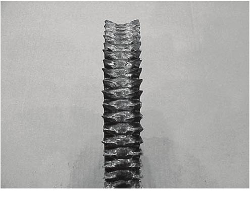


111 Transmissions 104
")


112 Transmissions Synchronizer Pin Torsional vibration in the drivetrain damaged the synchronizer assembly. Torsional vibration is a twisting and untwisting action in a shaft caused by the application of engine power (torque) or incorrect driveline phasing or angles. Torsional vibration is most likely absorbed at the transmission synchronizer and causes premature wear damage to all drivetrain components. Check the synchronizer assembly and pins. When torsional vibration occurs, pins can be fractured. Figure 9.42, Figure 9.43, and Figure A synchronizer damaged by torsional vibration require replacement. Follow AxleTech recommended service procedures to verify driveline angles and phasing are correct. 105


113 Transmissions Shift Collar Wear Shift collar teeth are worn and damaged, and full engagement does not occur. Replace the shift collar. Shift collar teeth surfaces are worn and rounded instead of flat and trapezoid shape. Figure Are the sides of the teeth surfaces polished? This indicates the collar is fully engaged into the mating gear. If wear does not extend to the end of the tooth, the collar isn t engaging fully into the gear. Is there a trapezoid shape on the ends of the teeth? Are teeth surfaces polished? If so, the shift collar is fully engaging and does not require replacement. Figure 9.46 and Figure It is normal to find shift collar damage in high-mileage transmissions. However, in lower-mileage transmissions, damage can occur if the manual shift mechanism malfunctions, the clutch is out-of-adjustment, or a driver didn t shift the transmission correctly. Check for a bent or twisted shift fork, worn or broken top cover, worn shift tower or twisted main shaft. Verify the shift lever motion isn t restricted. Try to determine if the driver had difficulty shifting the transmission. Worn collars cause raking and grinding during shifting. Follow AxleTech recommended maintenance practices and service procedures. Operate the vehicle within its approved application and weight limits. Teach drivers to correctly shift a transmission. 106

114 Transmissions Oil Seals If moisture, wetness, or oil drips on or around an axle oil seal, it is important to recognize if the seal is leaking, or if it only appears to be leaking. Recognizing a Leaking Seal Inspect the oil seal and surrounding area for wetness. If the seal and area appear very wet or visibly drip oil, or if oil is dripping from the bottom of the output seal retainer, replace the seal. Inspect the yoke for wetness. Check for a leak path leading to the rear lip of the seal. If wetness is around the yoke hub or a leak path leading to the rear lip of the seal, replace the seal. Example 1: Seal is Not Leaking None There is slight moisture from packing grease at assembly, but the area around the seal is dry. Figure Follow AxleTech recommended maintenance practices and service procedures. Recognizing a Seal that Appears to be Leaking Seals come pre-lubricated with grease that melts at low temperatures under normal operating conditions. Melted grease can moisten or wet the area between the yoke and the oil seal lip. When this happens, a leak path leading to the seal will not be present. If the seal is moist seal and a leak path is not present, do not replace the seal. A seal can also become moist from lubricants applied to the yoke or retainer bolts during assembly. When this happens, a leak path leading to the seal will not be present. If the seal is moist seal and a leak path is not present, do not replace the seal. Seal Test Procedure 1. Thoroughly clean and dry the area around the entire seal retainer casting, especially at the top. 2. Drive the vehicle for minutes at highway speeds. 3. Check for wetness or moisture on or around the seal. Also check for oil dripping from the seal. If either of these conditions is present, replace the seal. 107


115 Transmissions Example 2: Seal Appears to be Leaking A failure is possible. Inspect the seal. If a failure has occurred, determine its cause. Check for an oil path from the speedometer sensor to the yoke area. If an oil path is present, the seal is leaking. If an oil path is not present, but oil is around the seal, the seal requires replacement. Both of these conditions can occur at the same time. Figure Check the lubricant level. If it is low, replace the seal. If not, monitor the seal for leaks. Follow AxleTech recommended maintenance practices and service procedures. Example 3: Seal Appears to be Leaking A failure is possible. Inspect the seal. If a failure has occurred, determine its cause. Check for an oil path from the cover bolts to the yoke area. If an oil path is present, the seal is leaking. If an oil path is not present, but oil is around the seal, the seal requires replacement. Both of these conditions can occur at the same time. Figure Clean oil and dirt from the carrier. Check the lubricant level. If it is low, replace the seal. If not, monitor the seal for leaks. Follow AxleTech recommended maintenance practices and service procedures. 108

116 Transmissions Example 4: The Seal is Leaking Most likely, dirt or contaminants have entered the seal, or the seal s service life is expended. Inspect the yoke hub for wetness. Look for an oil leak path leading to the rear lip of the seal, which indicates that the seal is leaking and requires replacement. The seal requires replacement, even if an oil path is not present from the speed sensor, shift tower, and retainer bolts. Figure Follow AxleTech recommended maintenance practices and service procedures. Troubleshooting and Diagnostics Types of Problems When checking a problem with a manual transmission, the first thing to do is to verify the service condition. Talk to the driver, the mechanic or the service manager. If possible, take the vehicle for a test drive. There are three main types of problems: Leaks Noise and/or vibration Operating conditions Use the diagnostic tables and charts provided in this section as a starting point to diagnose the root cause of the problem. The information contained in these resources is not completely inclusive. Technicians should call AxleTech Customer Service at or via at service.na@axletech.com for futher assistance. 109
117 Transmissions Leaks Check the transmission for transmission oil leaks. If oil is on or under the transmission, verify the leak is transmission oil and not engine oil, coolant, or other lubricants. Noise If a noise is the problem, find out the sound of the noise. Growling or humming, or grinding Hissing, thumping or bumping Rattles Squealing Whining Vibration When checking a noise or a vibration, find out when the problem occurs. When the transmission is in neutral or in gear During upshifts or downshifts Operating Conditions When the transmission is not operating correctly, find out when the problem occurs. In neutral or in gear During upshifts or downshifts In high range or low range In direct range or overdrive range, 13-speed transmissions only Also, find out what the transmission does during the problem. Does not stay in the selected gear Does not stay in the selected range Does not select all gears Does not select all ranges Overheats Does not operate In all gears or specific gears In the high range or low range In direct range or overdrive range, 13-speed transmission only During coast or acceleration With the vehicle loaded or unloaded 110
118 Transmissions Troubleshooting Other Systems Verify the transmission is the cause of the problem. System Check For Repairs Engine Systems 1. Loose or missing fasteners 1. Replace missing fasteners. Tighten to the specified torque. 2. Engine idle speed out-of-specifications 2. Adjust the idle speed to the specified range. 3. Loose or damaged engine mounts 3. Tighten the fasteners to the specified torque. Replace the damaged mounts. 4. Out-of-balance fan 4. Replace the fan. 5. Damaged engine fan 5. Repair or replace as required. Clutch Systems 1. Loose or missing fasteners 1. Replace the missing fasteners. Tighten to the specified torque. 2. Clutch out-of-adjustment 2. Adjust the clutch. 3. Clutch assembly out-of-balance 3. Replace the clutch assembly. 4. Worn or damaged pilot bearing 4. Replace the pilot bearing Driveshaft Systems Suspension Systems Remote Shift Systems 1. Driveshaft system requires lubrication 1. Lubricate the driveshaft system. 2. Worn or damaged u-joints and/or yokes 2. Replace the u-joints and/or yokes. 3. Driveshaft out-of-balance 3. Balance the driveshaft correctly or replace the driveshaft. 4. Center bearings not installed correctly or 4. Install the center bearings correctly or replace. damaged 5. Driveline angles not correct 5. Adjust the driveline angles to the manufacturer s specifications. 1. Loose or missing fasteners 1. Replace the missing fasteners. Tightened to the specified torque. 2. Damaged suspension components 2. Repair or replace the damaged suspension components. 3. Driveline touching frame 3. Adjust driveline to not touch frame. 4. Loose or damaged cab mounts 4. Tighten loose fasteners to the specified torque. Replace any damaged mounts. 5. Leaks in air suspension system 5. Repair the air leaks. Check all valves for correct operation. 1. Low lubricant level 1. Fill to the specified level. 2. Linkage out of adjustment 2. Adjust the linkage. 3. Linkage binding or unable to move 3. Lubricate, repair, or replace the linkage. 111
119 Transmissions Troubleshooting Leaks Before troubleshooting a leak condition, perform the following conditions. Refer to the table below for diagnostics. 1. Clean the outside of the transmission to remove all the dirt. 2. Operate the vehicle to verify the leak is coming from the transmission. 3. Verify the fluid is transmission oil. 4. Verify the transmission housings are not cracked or broken. System Check For Repairs Leaks In-Vehicle Repair 1. Missing fasteners 1. Replace the missing fasteners. Tighten to the specified torque. 2. Loose fasteners 2. Tighten to the specified torque. 3. High oil level 3. Drain to the specified level. 4. Unspecified oil in transmission 4. Drain the oil. Install the specified oil. 5. Clogged or dirty breather vent 5. Clean the breather vent. 6. Damaged yoke 6. Replace the yoke. 7. Damaged output shaft seal 7. Replace the output shaft seal. 1 Leaks Remove and Disassemble Transmission 1. Damage gaskets or sealing material 1. Replace the gaskets or sealing material. 2. Cracked or broken housing 2. Replace the housing. 3. Oil leaking from breather vent Replace the piston shaft seal. 1 If the transmission continues to leak and the output shaft seal and the yoke have been replaced, remove and replace the output shaft assembly. 2 Place the transmission in Low Range and operate the vehicle. If air leaks from the breather vent, the range shaft seal must be replaced. 112
120 Transmissions Troubleshooting Noise For all noise conditions, check the following before disassembling the transmission. Refer to the table below for diagnostics and for an explanation of additional repairs that may be required. 1. Check the oil level is even with the bottom of the fill plug hole. 2. Verify the correct oil is used. 3. Verify the driveline angles of the transmission are correct. 4. Verify the transmission is correctly installed. 5. Remove the drain plug. Check for any metal shavings, gasket material, or any other material in the oil. Condition Cause Repair Growling, Humming, or Grinding 1 1. Worn or damaged gears 1. Replace the gears. 2. Worn bearings (humming only) 2. Replace the bearings. Hissing, Thumping, or Bumping 2 1. Damaged bearings (hissing only) 1. Replace the bearings. 2. Damaged gear teeth 2. Replace the gears. (thumping or bumping only) Rattles - In-Vehicle Repair 1. Engine idle speed not within specifications 1. Adjust the idle speed to the specified RPM. 2. Engine does not operate on all 2. Adjust or repair the engine. cylinders. 3. Clutch intermediate or center plate binding in housing 3 3. Repair or replace the intermediate or center plate. 4. Other systems 4. Verify the transmission is the source of the rattle condition. 5. Incorrect shim installation on the PTO unit. 5. Install the correct shims onto the PTO unit. Rattles - Remove and Disassemble Transmission 1. Damaged washers between main shaft gears 1. Replace the washers between the main shaft gears. Squealing or Whining - In-Vehicle Repair 4 1. Incorrect shim installation on the PTO unit 1. Install the correct shims onto the PTO unit. Squealing or Whining - Remove and 1. Damaged bearings 1. Replace the bearings Disassemble Transmission 4 2. End play of countershafts not within specifications 2. Adjust the countershaft end play within specifications. 1 Growling and humming are associated with the first stages of the condition. Grinding is associated with the severe stages of the condition. 2 Hissing is associated with the first stages of the condition. Thumping and bumping are associated with the severe stages of the condition. 3 If the noise occurs when the clutch is engaged and stops when the clutch is disengaged, the intermediate or center plate is the cause of the rattle. 4 Whining is a medium-pitched noise. Squealing is a high-pitched noise. 113
121 Transmissions Troubleshooting Vibration Before troubleshooting a vibration, perform the following conditions. Refer to the table below for diagnostics. 1. The engine idle speed is within the specified range. 2. The engine is operating correctly. 3. The u-joints, yokes, and driveshafts are in good condition. Check the driveline angles. Correct as necessary. 4. The u-joints, yokes, and driveshafts are correctly aligned and/or balanced. Correct as necessary. 5. Check the air bag height. Correct as necessary. System Check For Repairs Vibration In-Vehicle Repair 1. Fasteners do not remain tight. 1. Tighten the fasteners. If the fasteners do not remain tight, replace the fasteners or the housing. Vibration Remove and Disassemble 1. Damaged bearings 1. Replace the bearings. Transmission 2. Cracked or broken housing 1 2. Replace the synchronizer. 1 If the transmission does not shift correctly into the selected range, broken or loose synchronizer pins are the result of the vibration condition. 114
122 Transmissions Troubleshooting Operating Conditions Refer to the table below to troubleshoot operating conditions. For all Range Shift System diagnostics, refer to the flowcharts in this section. Condition Cause Repair Transmission Slips Out of the Selected 1. The air lines and fittings are loose. 1. Tighten the air lines and fittings. Range - In-Vehicle Repair 1 2. Obstructions are in the air lines. 2. Change the routing or replace the air lines. 3. Check the operation of the filter/ regulator assembly 3. Replace the filter/regulator assembly if the pressure at the delivery port is not within specification. 4. The range piston is damaged 4. Replace the range piston. 5. The nut fastening the piston to the 5. Tighten or replace the nut. shift shaft in the range shift cylinder is loose or missing Transmission Slips Out of the Selected 1. The teeth in the sliding clutch are 1. Replace the sliding clutch. Range Remove and Disassemble Transmission 1 worn 2. The shift fork is bent or worn 2. Replace the shift fork. 3. The collar on the range shift fork is worn 3. Replace the collar on the range shift fork. Transmission is Slow to Shift or Unable to Shift into the Selected Range In-Vehicle Repair 1 Transmission is Slow to Shift or Unable to Shift into Selected Range - Remove and Diassemble Transmission 1 1. The air lines and fittings are loose or 1. Tighten or replace the air lines or leaking fittings. 2. Obstructions are in the air lines 2. Change the routing or replace the air lines. 3. The filter/regulator assembly does 3. Replace the filter/regulator not operate correctly assembly if pressure at the delivery port is not within specification. 4. The piston or o-rings in the piston 4. Replace the piston or damaged housing are damaged o-rings 5. The neutral switch is worn or 5. Test and replace the neutral switch damaged 6. The shift knob is damaged 6. Test and replace the shift knob 1. The output shaft is damaged 1. Replace the output shaft. 2. The synchronizer springs or pins are 2. Replace the synchronizer springs or broken or missing synchronizer 3. The synchronizer is damaged 3. Replace the synchronizer. 4. The shift shaft in the range cylinder 4. Replace the shift shaft. is bent or broken 5. The shift fork in the range cylinder is 5. Replace the shift fork. bent or broken 115
123 Transmissions Condition Cause Repair Transmission Slips Out of the Selected Gear - In-Vehicle Repair 1. The clutch is used incorrectly 1. Ensure the driver uses the clutch correctly. 2. The linkage is binding or does not move freely 2. Lubricate, repair, or replace the linkage. 3. The clutch is out of adjustment 3. Adjust the clutch and ensure it engages and releases correctly. 4. The remote shift linkage is out of 4. Adjust the remote shift linkage adjustment 5. The engine or cab mounts are loose or damaged 5. Tighten the fasteners on the loose mounts to the specified torque. Replace damaged mounts. 6. The driveline angles are incorrect 6. Adjust the driveline angles 7. The detent spring in the top cover is weak or broken 7. Replace the detent spring in the top cover assembly. Transmission Slips Out of the Selected 1. The pads on the shift fork are worn 1. Replace the shift fork. Gear Remove and Disassemble 2. The teeth in the sliding clutch are 2. Replace the sliding clutch. Transmission worn 3. The fork slot on the sliding clutch is 3. Replace the sliding clutch. worn 4. The key on the main shaft is broken. 4. Replace the key or main shaft. 5. The main shaft is twisted 5. Replace the main shaft. Transmission is Hard to Shift or Unable to Shift into the Selected Gear In- Vehicle Repair Transmission is Hard to Shift or Unable to Shift into the Selected Gear Remove and Disassemble Transmission 1. The vehicle is operated incorrectly 1. Ensure that the driver operates the vehicle correctly. 2. The clutch is out-of-adjustment 2. Adjust the clutch. Ensure that the clutch engages and releases correctly. 3. The remote shift linkage is binding 3. Lubricate, repair or replace the or unable to move remote shift linkage. 4. The cab or engine mounts are loose 4. Tighten the fasteners of the loose or damaged mounts to the specified torque. 5. The detent spring is too strong or 5. Replace the detent springs. broken 1. Bent shift shaft in top cover 1. Replace the shift shaft. assembly 2. Burr on the shift shaft in the top 2. Replace the shift shaft. cover assembly 3. Cracked top cover assembly 3. Replace the top cover assembly. 4. The main shaft is twisted 4. Replace the main shaft. 5. The key on the main shaft is broken 5. Replace the key or the main shaft. 6. Broken or bent shift fork on the 6. Replace the shift fork. sliding clutch 116
124 Transmissions Condition Cause Repair Transmission Grinds on Initial Engagement In-Vehicle Repair 1. The driver does not operate the vehicle correctly 1. Ensure the driver operates the vehicle correctly. 2. The clutch is out-of-adjustment. 2. Adjust the clutch. Verify that the clutch engages and releases correctly. 3. The clutch brake is worn, damaged or missing 3. Replace the clutch brake. Verify that the clutch engages and releases correctly. 4. The clutch or remote shift housing linkage is binding or unable to move 4. Lubricate, repair or replace the linkage. 5. Worn bushings in side of clutch housing 5. Replace the bushings in the clutch housing. Shift Lever Locks or Sticks in Gear 1. The remote shift linkage is out-ofadjustment 1. Adjust the remote shift linkage. In-Vehicle Repair 2. The clutch linkage needs adjustment 2. Adjust the clutch linkage. 3. The linkage is binding or unable to move 3. Lubricate, repair or replace the linkage. 4. The cab or engine mounts are loose or damaged 5. The shift stub lever is not engaged in the shift sleeve 4. Tighten the fasteners on the loose mounts to the specified torque. Replace the damaged mounts. 5. Reinstall the shift tower and verify the engagement of the stub lever into the shift sleeve. Shift Lever Locks or Sticks in 1. The shift fork in the top cover is bent 1. Replace the shift fork. Gear Remove and Disassemble 2. The shift shaft in the top cover is 2. Replace the shift shaft. Transmission damaged 3. The main shaft is damaged 3. Replace the main shaft. Transmission Overheats In-Vehicle 2, 3 1. The oil level is incorrect 1. Fill the oil to the specified level. 2. Incorrect oil 2. Drain the oil. Use the specified oil. 3. The temperature gauge is damaged 4 3. Replace the temperature gauge. Transmission Does Not Operate 1. The free running gears are locked 1. Replace the gears. Remove and Disassemble 2. The gear sets are mismatched 2. Install the correct gear sets. Transmission 3. The timing marks on the gears are 3. Align the timing marks on the gears. not aligned 4. The shafts are broken 4. Replace the shaft. 1 Also refer to the Range Shift System diagnostic flowcharts in this section to troubleshoot all range system problems. 2 If a noise is present along with the overheating condition, also refer to the noise troubleshooting table in this section. 3 If the oil is at the specified level and the specified oil is used, but the transmission overheats and the oil smells burned, the transmission must be disassembled and inspected. 4 If the oil does not have a burned smell and the temperature gauge indicates overheating, remove and replace the gauge. 117

125 Transmissions Range Shift System Diagnostics for Platform G Transmissions These flowcharts provide diagnostic information for ZF-FreedomLine Platform G transmission range shift systems. When using diagnostics to troubleshoot system faults, it is important to follow these flowcharts step-bystep and use the diagnostic procedures in the sequence outlined below. Figure 9.52, Figure 9.53, and Figure
126 Transmissions Troubleshooting Flowcharts Use the following recommended service procedures to repair and test the system. If a fault still exists, or if a new fault is found, repeat the mechanical checks and both the low-range and high-range electrical checks until all the faults have been repaired. 119
127 Transmissions Mechanical Checks Follow the mechanical checks flowchart to verify all mechanical systems function correctly. Repair all mechanical issues BEFORE performing electrical checks. Figure
128 Transmissions Low Range Electrical Checks Follow the low range electrical checks flowchart to verify the low electrical system functions correctly. Perform low range electrical checks AFTER mechanical checks and BEFORE high range electrical checks. Figure
129 Transmissions High Range Electrical Checks Follow the high range electrical checks flowchart to verify the high range electrical system functions correctly. Perform high range electrical checks AFTER mechanical checks and low range electrical checks. Figure
130 Transfer Cases Transfer Cases Parts Analysis Overview DANGER ALWAYS WEAR PROPER EYE PROTECTION AND OTHER REQUIRED PERSONAL PROTECTIVE EQUIPMENT TO PREVENT PERSONAL INJURY WHEN INSPECTING HEAVY VEHICLE COMPONENTS. This section provides a parts analysis process to determine why transfer cases failed during operation, what to look for when inspecting parts, and how to prevent failures from occurring again. Most of the time, answers can be found by visually inspecting a failed component. Sometimes, however, this process may require specialized knowledge or equipment. Why a product fails can be difficult to determine, and a failure can vary in appearance from vehicle to vehicle. Failures in models from the same manufacturer can also vary, so it is important to use the information presented here as a guide, not a rule, when performing parts analysis inspections. Causes of Transfer Case Component Failure Front Idler Bearing Incorrect towing from the front of the vehicle without removing the driveshaft from the rear output shaft of the transfer case to the rear drive axle, or not removing the rear drive axle shafts on the tires that contact with the road. Damage to the front idler bearing is found caused by a lack of lubrication. Figure Damage to the front idler bearing cone and/or rollers is found caused by heat and/or a lack of lubrication. Figure 10.1 and Figure Damage to the front idler cup is found caused by heat and/or a lack of lubrication. Figure The bearing cage is destroyed. Figure The input shaft surface and phosphate coating for the low gear bearing journal show eccentric wear, which means wear shows on approximately 180 of the bearing journal, but not on the 180 of the opposite side of the input shaft journal. This condition indicates the low gear is rotating, but the input shaft is not rotating; or the input shaft is rotating at a slower speed during towing. Figure There could be signs of gear clash wear at the end of the high/low clutch collar teeth on the high gear side. This is caused by the inclination of the vehicle as it loses air during towing. Figure 10.5 and Figure Usually, there are no other signs of heat present on other bearings. This damage can occur when the transfer case is rotating, and oil is not flowing from the lubrication pump. If the input shaft on the transfer case is not rotating, the oil pump and/or lubricant splash does not reach the bearings during vehicle inclination while towing. Insufficient lubricant resulting from incorrect towing procedures will damage the front idler bearing. The transfer case can fail during towing, or when the vehicle is in operation. 123


131 Transfer Cases Follow AMT-0155 AxleTech Towing Service Manual. To obtain this publication, see Service Notes on page ii. 124

132 Transfer Cases Front Output Shaft Incorrect towing from the rear of the vehicle without removing the prop shaft from the transfer case to the axle with the wheels on the road. This will cause a spinout condition between the front output helical gear and the front output shaft. Front output shaft and gear spinout damage caused from friction welding. Figure Front output shaft rear bearing cup is damaged from heat. Figure Front output shaft bearing cup and cage is completely destroyed from heat. Figure There is no damage to the All Wheel Drive (AWD) clutch collar because it was not engaged. Heat from the other parts caused slight discoloration of the clutch collar. Figure Spinout between the front output shaft journal and the front output shaft gear caused a friction welding of the two components as well as damage to the front output shaft bearing. No signs of wear on the front input shaft from the oil pump sealing rings indicate the input shaft was not turning during towing. Figure This damage is caused by the transfer case turning during towing. The transfer case may fail during towing or while driving the vehicle after it has been incorrectly towed. Follow AMT-0155 AxleTech Towing Service Manual. To obtain this publication, see Service Notes on page ii. 125


133 Transfer Cases 126
134 Notes Notes 127
135

136 Customer Service (0) Customer Service Fax OE: sales@axletech.com Aftermarket: aftermarket@axletech.com
Parts Failure Analysis
 Manual TP-0445 Parts Failure Analysis Supersedes Manual TP-87123 Revised 04-08 Service Notes About This Publication This publication provides a parts analysis process to help you determine why parts failed
Duplex Cam Mechanical (DCM) Brakes
 Brakes") Maintenance Manual MM-0712 Duplex Cam Mechanical (DCM) Brakes Issued 11-07 Service Notes About This Manual This manual provides service and repair procedures for Meritor duplex cam mechanical (DCM) brakes.
Maintenance Manual MM-0712 Duplex Cam Mechanical (DCM) Brakes Issued 11-07 Service Notes About This Manual This manual provides service and repair procedures for Meritor duplex cam mechanical (DCM) brakes.
TECHNICAL BULLETIN. Yoke Removal and Installation Procedure for Meritor Drive Axles. Remove the Yoke and Pinion Seal WARNING CAUTION CAUTION.
 Issued 11-99 TECHNICAL BULLETIN Yoke Removal and Installation Procedure for Meritor Drive Axles Remove the Yoke and Pinion Seal Figure 1 WARNING Park the vehicle on a level surface. Block the wheels to
Rear Axle Single-Reduction Carrier
 Revised 08-0 Rear Axle Single-Reduction Carrier Model MS-3 Maintenance Manual MM-030 Service Notes Service Notes Notes About This Manual This manual provides instructions for Meritor s model MS-3 single-reduction
SCL 25 SERIES DRY DISC BRAKE CALIPERS
 MAINTENANCE MANUAL SCL 25 SERIES DRY DISC BRAKE CALIPERS MANUFACTURED BY 2300 OREGON ST., SHERWOOD 97140, OR U.S.A. PHONE: 503.625.2560 FAX: 503.625.7980 E-MAIL: cranes@alliedsystems.com WEBSITE: http://www.alliedsystems.com
Input Adjusting Ring Leak Repair Procedure for Meritor MT-14X Series Forward Differential Carriers
 Revised 01-16 Technical Bulletin Input Adjusting Ring Leak Repair Procedure for Meritor MT-14X Series Forward Differential Carriers Revised 1 Technical 01- Bulletin 16 Hazard Alert Messages Read and observe
SERVICE MANUAL ESM-0914E. September Planetary Axle Wheel Ends PRC485Q PRC785Q PRC485W3H PRC785W3H PRC785P PRLC1015HDB
 SERVICE MANUAL ESM-0914E September 2018 Planetary Axle Wheel Ends PRC485Q PRC785Q PRC485W3H PRC785W3H PRC785P PRLC1015HDB Table of Contents Table of Contents Service Notes...ii Asbestos and Non-Asbestos
Off-Highway Axle Planetary Wheel Ends
 Maintenance Manual MM-1189 Off-Highway Axle Planetary Wheel Ends Revised 06-16 Service Notes About This Manual This manual provides service and repair procedures for planetary wheel ends on off-highway
Medium-Duty Front Drive Steer Axles
 Maintenance Manual MM-0170 Medium-Duty Front Drive Steer Axles MX-120 and MX-120-EVO Series Applies to 120 Standard and 120-HR High-Retardation Carriers Revised 02-17 Service Notes About This Manual This
Wheel Equipment. Disc Wheel Hubs Brake Drum Failure Analysis Revised Maintenance Manual MM-99100
 Maintenance Manual MM-99100 Wheel Equipment Disc Wheel Hubs Brake Drum Failure Analysis Revised 09-12 Supersedes Dayton Walther s Disc Wheel Hubs Safety, Installation and Maintenance Manual for Class 6,
Module 1: Introduction to Drive Trains
 Introduction ÂÂ Basic Components of a Drive Train Operation of a Drive Train Working Applications Types of Drives Types of Gears Formula for Calculating Gear Ratio Determining Gear Rotation Introduction
Air-Actuated Disc Brake
 Issued 05-00 $2.50 Air-Actuated Disc Brake Maintenance Manual MM-99108 D-LISA Service Notes Service Notes Before You Begin This manual provides installation and maintenance procedures for Meritor s air-actuated
A. Adapter A metal component that fastens the caliper to the knuckle. Some brake systems do not use adapters.
 BRAKES UNIT 5: DISC BRAKE DIAGNOSIS AND REPAIR LESSON 3: SERVICE DISC BRAKE CALIPERS I. Terms and definitions A. Adapter A metal component that fastens the caliper to the knuckle. Some brake systems do
Spicer. Drive Axles. Service Manual. Failure Analysis AXSM-0020 December 2015
 Spicer Drive Axles Service Manual Failure Analysis AXSM-0020 December 2015 Table of Contents Introduction Overview... 1 Failure Prevention Correct Specifications... 2 Driving Practices...3 Maintenance,
Brake System H TX, H2.0TXS [B475]; H TX [B466] Safety Precautions Maintenance and Repair
![Brake System H TX, H2.0TXS [B475]; H TX [B466] Safety Precautions Maintenance and Repair](/thumbs/86/93834005.jpg "Brake System H TX, H2.0TXS [B475]; H TX [B466] Safety Precautions Maintenance and Repair") HMM180001 Brake System H1.5-1.8TX, H2.0TXS [B475]; H2.5-3.5TX [B466] Safety Precautions Maintenance and Repair When lifting parts or assemblies, make sure all slings, chains, or cables are correctly fastened,
HMM180001 Brake System H1.5-1.8TX, H2.0TXS [B475]; H2.5-3.5TX [B466] Safety Precautions Maintenance and Repair When lifting parts or assemblies, make sure all slings, chains, or cables are correctly fastened,
Single Rear Drive Axles, Rear-Rear Tandem Drive Axles and Front Drive Steer Axles Revised 02-18
 Maintenance Manual 5A Single-Reduction Differential Carriers Single Rear Drive Axles, Rear-Rear Tandem Drive Axles and Front Drive Steer Axles Revised 02-18 Service Notes About This Manual This manual
TL (TIL03029) REPAIR MANUAL. Telma model FN72-40 replacement on Arvin Meritor forward tandem carrier. Page 1 of JUL-11.
 REPAIR MANUAL. Telma model FN72-40 replacement on Arvin Meritor forward tandem carrier. Page 1 of JUL-11.") REPAIR MANUAL Telma model FN72-40 replacement on Arvin Meritor forward tandem carrier Page 1 of 10 29-JUL-11 Exploded view P/N: FE962100 Stator Carrier Kit Includes: Qty Description Telma P/N 1 Stator
REPAIR MANUAL Telma model FN72-40 replacement on Arvin Meritor forward tandem carrier Page 1 of 10 29-JUL-11 Exploded view P/N: FE962100 Stator Carrier Kit Includes: Qty Description Telma P/N 1 Stator
Issued Bus and Coach. Front Axles. Maintenance Manual 23 FH 941 FH 945 FH 946
 Issued 7-98 Bus and Coach Front Axles Maintenance Manual 23 17100 17101 17110 17111 FH 941 FH 945 FH 946 Service Notes Before You Begin This manual provides maintenance procedures for Meritor s bus and
T-276 Two-Speed Carrier Mounted Input Transmission Transmission montée en entrée de nez de pont à deux vitesses
 TM T-276 Two-Speed Carrier Mounted Input Transmission Transmission montée en entrée de nez de pont à deux vitesses Maintenance Manual MM5.2 Manuel de maintenance MM5.2 Issued 10-03 Edité Octobre 03 Models
SCL 2 Series Dry Disc Brake Calipers
 $2.50 SCL 2 Series Dry Disc Brake Calipers Maintenance Manual No. 4S Revised 11-96 SCL 2-13 SCL 2-26 SCL 2-15 SCL 2-28 SCL 2-22 SCL 2-30 SCL 2-24 Service Notes Important Information This manual contains
TO INDEX DIFFERENTIAL FRONT DIFFERENTIAL CARRIER OIL SEAL (4WD) FRONT DIFFERENTIAL CARRIER ASSEMBLY (4WD) REAR DIFFERENTIAL CARRIER OIL SEAL
 FRONT DIFFERENTIAL CARRIER ASSEMBLY (4WD) REAR DIFFERENTIAL CARRIER OIL SEAL") TO INDEX DRIVE LINE / AXLE DIFFERENTIAL DIFFERENTIAL SYSTEM PRECAUTIONS.............................................. OPERATION CHECK......................................... PROBLEM SYMPTOMS TABLE.................................
TO INDEX DRIVE LINE / AXLE DIFFERENTIAL DIFFERENTIAL SYSTEM PRECAUTIONS.............................................. OPERATION CHECK......................................... PROBLEM SYMPTOMS TABLE.................................
Spicer Drive Axles. More time on the road. Service Manual. Failure Analysis AXSM0020
 Spicer Drive Axles More time on the road Service Manual Failure Analysis AXSM0020 JUne 2009 Table of Contents Introduction Overview... 2 Failure Prevention Correct Specifications... 3 Glossary and Nomenclature
Four-Piston Quadraulic Disc Brake Caliper
 Maintenance Manual MM-2075 Four-Piston Quadraulic Disc Brake Caliper Revised 08-09 Service Notes About This Manual This manual provides instructions for Meritor four-piston Quadraulic disc brake calipers.
Heavy-Duty P Series Cam Brakes
 Maintenance Manual MM-0440 Heavy-Duty P Series Cam Brakes Issued 09-04 Service Notes About This Manual This manual provides maintenance and service information for Meritor heavy-duty P Series cam brakes.
Gear Drives. A third gear added to the system will rotate in the same direction as the drive gear Equal diameters = Equal number of teeth = Same speed
 Gear Drive Systems Gear Drives Gear Drive: Synchronous mechanical drive that uses gears to transfer power Gear: A toothed wheel that meshes with other toothed wheels to transfer rotational power Pinion
MAINTENANCE MANUAL. Differential Axle MS Edition october/11
 MAINTENANCE MANUAL Differential Axle MS - 113 Edition october/11 Index 1 - Notes to Technical Assistance... 03 2 - Exploded View MS-113... 04 3 - Exploded View MS-113 Plus... 05 4 - Introduction... 06
Single-Reduction Differential Carriers
 Revised 0-0 Single-Reduction Differential Carriers Single Rear Drive Axles, Rear-Rear Tandem Drive Axles and Front Drive Steer Axles Maintenance Manual 5A RS and RT Series Single-Reduction Axles (Single,
Single Reduction Differential Carriers
 Revised 10-00 $2.50 Single Reduction Differential Carriers Maintenance Manual 5 Standard Carriers Including: Single Axles, Rear of Tandem Axles, Front Drive Steering Axles Excluding RS and RT Series (Rear
DIAGNOSIS AND TESTING
 205-02B-1 DIAGNOSIS AND TESTING Rear Drive Axle and Differential Special Tool(s) Dial Indicator Gauge with Holding Fixture 100-002 (TOOL-4201-C) or equivalent 205-02B-1 4 Has the driveline system been
Maintenance Manual MM-0220 Single Reduction Differential Forward Carrier MD15. Issue November 2017
 Maintenance Manual MM-0220 Single Reduction Differential Forward Carrier MD15 Issue November 2017 Service Notes Before You Begin This publication provides installation and maintenance procedures for the
Injector. General Information CAUTION. Use only the specified injector for the engine.
 Page 1 of 32 006-026 Injector General Information CAUTION Use only the specified injector for the engine. All engines use closed nozzle, hole-type injectors. However, the injectors can have different part
Four-Piston Quadraulic TM Disc Brake Caliper
 Issued 01-01 $2.50 Four-Piston Quadraulic TM Disc Brake Caliper Maintenance Manual MM-2075 Service Notes Service Notes Before You Begin This manual provides maintenance and service procedures for Meritor
Module 6: Air Foundation Brakes
 Air Brakes Terms and Definitions Basic Components That Make Up Air Foundation Brakes Types of Air Foundation Brakes Parts of a Cam Foundation Brake Parts of a Wedge Foundation Brake Parts of a Disc Foundation
Amboid Rear Differential Carrier
 Maintenance Manual MM-0250 Amboid Rear Differential Carrier Rear/Rear Carrier on MT-40-143MA-N Tandem Drive Axles Revised 09-05 Service Notes About This Manual This manual provides instructions for the
Copyright 1998 Inter-Industry Conference On Auto Collision Repair v.4.0
 Uniform Procedures For Collision Repair BR11 Brakes 1. Description This procedure describes repair, replacement, and inspection requirements for collisiondamaged brake systems. 2. Purpose The purpose of
Automatic Slack Adjuster
 Revised 03-98 $2.50 Automatic Slack Adjuster Maintenance Manual 4B Service Notes Service Notes Before You Begin This manual provides maintenance and service procedures for Meritor s automatic slack adjuster.
Meritor Clutch. Revised $2.50. Clutches. Maintenance Manual 25A. AutoJust TM LTD
 Meritor Clutch Revised 04-01 $2.50 Clutches Maintenance Manual 25A AutoJust TM LTD Service Notes Service Notes Before You Begin This manual provides maintenance and service procedures for Meritor s AutoJust
Installation Instructions
 Preparing your vehicle to install your brake system upgrade 1. Rack the vehicle. 2. If you don t have a rack, then you must take extra safety precautions. 3. Choose a firmly packed and level ground to
Maintenance Information
 16573370 Edition 2 February 2014 Air Grinder 99V Series Maintenance Information Save These Instructions Product Safety Information WARNING Failure to observe the following warnings, and to avoid these
PROPELLER SHAFTS 16-1 PROPELLER SHAFTS CONTENTS
 Z PROPELLER SHAFTS 16-1 PROPELLER SHAFTS CONTENTS page GENERAL INFORMATION... 1 PROPELLER SHAFT REPLACEMENT... 7 SERVICE DIAGNOSIS/PROCEDURES... 3 page TORQUE SPECIFICATIONS... 14 UNIVERSAL JOINT REPLACEMENT...
Maintenance Instructions
 General Note These instructions contain information common to more than one model of Bevel Gear Drive. To simplify reading, similar models have been grouped as follows: GROUP 1 Models 11, 0, 1,, (illustrated),,
2.- HANDLING OF VALVES BEFORE ASSEMBLY 3.- FITTING THE VALVE TO THE REST OF THE ASSEMBLY 5.- PERIODICAL INSPECTION OF THE VALVE AND MAINTENANCE
 Page 1 of 16 CONTENTS 1.- INTRODUCTION 2.- HANDLING OF VALVES BEFORE ASSEMBLY 3.- FITTING THE VALVE TO THE REST OF THE ASSEMBLY 4.- OPERATION OF A BALL VALVE 5.- PERIODICAL INSPECTION OF THE VALVE AND
CAUTION: Do not clean, wash or soak transmission seals in cleaning solvents. Dry all parts with compressed air.
 «1993 Thunderbird/Cougar Table of Contents» «Group 07: TRANSMISSION» «Section 07-03: Transmission, Manual--M5R2» «CLEANING AND INSPECTION» Transmission Cleaning CAUTION: Do not clean, wash or soak transmission
2002 F-Super Duty /Excursion Workshop Manual
 Page 1 of 5 SECTION 205-02D: Rear Drive Axle/Differential Ford 10.50-Inch Ring Gear 2002 F-Super Duty 250-550/Excursion Workshop Manual DIAGNOSIS AND TESTING Procedure revision date: 02/02/2005 Rear Drive
Issued 8-95 $2.50. PD 1591 Series. Dry Disc Brake Calipers. Maintenance Manual No. 4AA
 Issued 8-95 $2.50 PD 1591 Series Dry Disc Brake Calipers Maintenance Manual No. 4AA SERVICE NOTES This Maintenance Manual describes the correct service and repair procedures for Meritor PD 1591 Series
DiscPlus EX225 Air Disc Brake
 Maintenance Manual MM-0467 DiscPlus EX225 Air Disc Brake Revised 02-13 Service Notes About This Manual This manual provides installation and maintenance procedures for the DiscPlus EX225 air disc brake.
DC MOTOR MAINTENANCE ALL ELECTRIC LIFT TRUCKS PART NO SRM 294
 DC MOTOR MAINTENANCE ALL ELECTRIC LIFT TRUCKS PART NO. 897076 620 SRM 294 SAFETY PRECAUTIONS MAINTENANCE AND REPAIR When lifting parts or assemblies, make sure all slings, chains, or cables are correctly
1 of 9 7/19/2016 5:35 PM
 1 of 9 7/19/2016 5:35 PM PADS - FRONT/REAR BRAKE - SRT8 STANDARD PROCEDURE BRAKE PAD BURNISHING CAUTION: After installing NEW brake pads, keep in mind that braking effectiveness might be somewhat reduced
Wheel end service for greased wheel ends
 wheel ends Page 1 Tech tip Scope This document recommends procedures for servicing greased wheel ends. Included are SKF recommendations for manually adjusted, hard greased (NLGI 1, 2, and 3) and semi-fluid
WHEELS BEARINGS TIRES
 GROUP 22 WHEELS BEARINGS TIRES CONTENTS Page GENERAL INFORMATION 1 SERVICE DIAGNOSIS 1 SERVICE PROCEDURES... 2 WHEELS... 2 Page BEARINGS 2 TIRES 4 SPECIFICATIONS AND TIGHTENING REFERENCE.. In Rear of Manual
SPECIAL TOOLS Dodge Pickup 5.9L Eng R3500. Fig 1: Identifying Remover C-3985-B (Special Tool) 9/6/13 Printer Friendly View
 9/6/13 Printer Friendly View") Procedures 2003 Dodge Pickup 5.9L Eng R3500 manual transmission SPECIAL TOOLS Fig 1: Identifying Remover C-3985-B (Special Tool) www2.prodemand.com/print/index?content=tabs&module=true&tab=true&terms=true&ymms=false&classname=
Procedures 2003 Dodge Pickup 5.9L Eng R3500 manual transmission SPECIAL TOOLS Fig 1: Identifying Remover C-3985-B (Special Tool) www2.prodemand.com/print/index?content=tabs&module=true&tab=true&terms=true&ymms=false&classname=
Planetary Axle Wheel Ends Covered Planetary Spider Design Maintenance Manual No. 9E
 Issued 7-99 $2.50 Planetary Axle Wheel Ends Covered Planetary Spider Design Maintenance Manual No. 9E Rigid Axle Tandem and Tridem Axles Steering Axle PRLC 1925 PRC 4805 SPRC 1926 EPRC 4806 PSC 1875 PRLC
REASONS YOUR BEARINGS WILL FAIL. Ritbearing CORPORATION
 12 REASONS YOUR BEARINGS WILL FAIL Ritbearing Things break. No matter what you do, there is always a chance that products you own will fail. The same holds true for bearings, but that doesn t mean that
SECTION 6 5 SERVICE PROCEDURES AND SPECIFICATIONS. Body
 SECTION 6 5 SERVICE PROCEDURES AND SPECIFICATIONS Body Specifications 236 Protecting your vehicle from corrosion 237 Washing and waxing 238 Cleaning the interior 239 235 SPECIFICATIONS DIMENSIONS AND WEIGHT
Introduction. Lubrication Related Failures. Gear Couplings. Failure Analysis All Types (Page 1 of 7)
") All Types (Page 1 of 7) Introduction A gear coupling serves as a mechanical device which connects shafts of two separate machines and accommodates small amounts of shaft misalignment. Commercial gear couplings
All Types (Page 1 of 7) Introduction A gear coupling serves as a mechanical device which connects shafts of two separate machines and accommodates small amounts of shaft misalignment. Commercial gear couplings
Critical Areas of Setup: Although there are many steps to differential repair, there are 4 critical areas of setup that all differentials share:
 DISASSEMBLY: Integral style with rear cover (aka salisbury) 1. Support vehicle or rearend on suitable lift or stands. 2. Drain oil by removing differential cover. 3. Remove wheels, brake drums, rotors
SECTION ZF FRONT AXLE
 04-101.01/ 1 2011JA14 SECTION 04-101.01 6 3 5 1 2 9 1. Upper radius rod 2. Lower radius rod 3. Caliper 4. BRAKE Disk 5. Pneumatic connector 6. Hub 7. steering knuckle 8. Grease Fitting 9. Pneumatic connector
INSTRUCTION AND REPAIR MANUAL MODELS 341A, 342A AND 344A 6
 SECTION 6 ITEM 0 DATED JUNE 1998 SUPERSEDES ITEMS 1, 2, DATED MARCH 1992 INSTRUCTION AND REPAIR MANUAL MODELS 1A, 2A AND A 6 NOTE This repair manual is applicable to pump Models 1A, 2A and A. All photos
Rear Axle. Table of Contents
 Rear Axle Table of Contents Sub-Headings Safety 2 Warnings 2 Cautions 2 s 2 Introduction 2 Standard Single Reduction Carriers Without Differential Lock 5 Disassembly 6 Remove Differential Carrier from
What is Wear? Abrasive wear
 What is Wear? Written by: Steffen D. Nyman, Education Coordinator, C.C.JENSEN A/S It is generally recognized that contamination of lubricating and hydraulic oils are the primary cause of wear and component
Synchronous Belt Failure Analysis Guide
 Synchronous Belt Failure Analysis Guide Contents Part 1: Common Causes of Belt Failure Normal Belt Wear and Failure Belt Crimp Failures Shock Load Part 2: Improper Belt Installation Tension Introduction
HYDRAULIC ABS FOR MEDIUM-DUTY TRUCKS, BUSES AND MOTOR HOME CHASSIS MAINTENANCE MANUAL
 HYDRAULIC ABS FOR MEDIUM-DUTY TRUCKS, BUSES AND MOTOR HOME CHASSIS MAINTENANCE MANUAL Service Notes Service Notes Important Information This manual contains maintenance procedures for WABCO s Hydraulic
Spicer Driveshafts. Service Manual. DSSM3264 September 2007
 Spicer Driveshafts Service Manual DSSM3264 September 2007 Table of Contents Safety...................... 1 General Safety.......................... 1 Component Safety...................... 2 Driveline...........................
General Knowledge Test D. 1. Which of these statements about driving in areas with strong winds are true?
 General Knowledge Test D 1. Which of these statements about driving in areas with strong winds are true? a. Winds are especially a problem when coming out of tunnels. b. You should drive alongside other
HORSTMAN GREASED LIGHTNING CLUTCH
 HORSTMAN GREASED LIGHTNING CLUTCH Horstman s Greased Lightning (GL) clutch is designed for ultra high performance, and requires expert setup and a serious commitment to maintenance. Warning!!! 1. Clutch
Single-Reduction Forward Differential Carriers on Tandem and Tridem Axles
 Maintenance Manual 5L Single-Reduction Forward Differential Carriers on Tandem and Tridem Axles Revised 08-15 Service Notes About This Manual This manual provides maintenance and service information for
Model 320 / 320A Hinge Assembly
 MANUFACTURING CO. THE FIRST NAME IN QUALITY COUPLINGS Installation, Inspection, Operation & Maintenance Guide Model 320 / 320A Hinge Assembly IMPORTANT Read these instructions completely before installing,
INSTALLATION MANUAL. TORQ Locker TL GM 14 Bolt Installation Instructions. Made in USA By: Page 1 of 8
 INSTALLATION MANUAL TORQ Locker TL-19035 GM 14 Bolt Installation Instructions Made in USA By: Page 1 of 8 Page 2 of 8 INSTALLATION MANUAL TORQ Locker TL-19035 GM 14 Bolt Installation Instructions By: INTRODUCTION
SuperTrac. Axle. Service & Maintenance. Manual
 SuperTrac Axle Service & Maintenance Manual Table of Contents Page Exploded Views Section 1: General Information General Warnings Description of Axle Models Identifications Section 2: Installation Axle
TECHNICAL BULLETIN. TP Issued Servicing Rockwell s TB Series Trailer Axles with Unitized Hub Assemblies
 TECHNICAL BULLETIN TP-96175 Issued 12-96 Servicing Rockwell s TB Series Trailer Axles with Unitized Hub Assemblies TB Series Trailer Axles Introduction Rockwell s TB series trailer axle features a permanently
Service Manual. Spicer Drive Axle. AXSM-0400 September 2007
 Spicer Drive Axle Service Manual Spicer Drive Axle AXSM-0400 September 2007 This bulletin contains product improvement information. Dana Corporation is not commited or liable for canvassing existing product.
M-2300-M Mustang GT Rear Disc Brake Bracket Kit INSTALLATION INSTRUCTIONS
 Please contact the Tech Line for the most current instruction information (800) 367-3788!!! PLEASE READ THE FOLLOWING INSTRUCTIONS CAREFULLY PRIOR TO INSTALLATION!!! INTRODUCTION: This kit allows for the
MAINTENANCE MANUAL. Drivelines MM Edition october/11
 MAINTENANCE MANUAL Drivelines MM-96147 Edition october/11 Index 1 - Drivelines... 03 2 - Introduction... 05 3 - Inspection... 06 4 - RPL Series PermalubeTM... 12 5 - Full-Round... 23 6 - Wing-Style PermalubeTM...
2244 West McDowell Road Phoenix, AZ RACE (fax)
") 2244 West McDowell Road Phoenix, AZ 85009 602-257-9591 1-800-274-RACE 602-340-8429 (fax) www.hughesperformance.com HUGHES PERFORMANCE HP2211R VALVE BODY Installation Instructions rev. b 10-2016 For over
2244 West McDowell Road Phoenix, AZ 85009 602-257-9591 1-800-274-RACE 602-340-8429 (fax) www.hughesperformance.com HUGHES PERFORMANCE HP2211R VALVE BODY Installation Instructions rev. b 10-2016 For over
Cam Brakes and Automatic Slack Adjusters
 Maintenance Manual 4 Cam Brakes and Automatic Slack Adjusters Revised 08-16 Service Notes About This Manual This manual provides maintenance and service information for Meritor cam brakes and automatic
Single-Reduction Differential Carriers
 Revised 10-06 Single-Reduction Differential Carriers Maintenance Manual 5 Standard Carriers Including: Single Axles, Rear of Tandem Axles, Front Drive Steering Axles Excluding RS and RT Series (Rear Only),
ENGINE MEASUREMENTS ENGINE MEASUREMENTS AND SPECIFICATIONS CYLINDER HEAD. Measure Cylinder Compression. Using Telescoping Gauges and Hole Gauges
 ENGINE MEASUREMENTS AND SPECIFICATIONS Tool List Qty. Required Compression Gauge, 20 kgf/cm²: E-Z-GO Part No. N/A... 1 Compression Gauge Adapter, M14 1.25: E-Z-GO Part No. N/A... 1 Valve Seat Cutter, 45-35
Electric motor testing
 Electric motor testing MOTOR (MODELS EJ4-4001 AND EJ8-4001A) 23 GENERAL INFORMATION The vehicle is equipped with a 48-volt DC, shunt-wound, reversible traction motor. The shunt-wound motor is designed
 DRUM BRAKE RIMS Periodic inspection of drum brake rims is necessary to determine indications of uneven or excessive wear. In general, brake rim failures other that regular wear are caused by brake linings
2244 West McDowell Road Phoenix, AZ RACE (fax)
") 2244 West McDowell Road Phoenix, AZ 85009 602-257-9591 1-800-274-RACE 602-340-8429 (fax) www.hughesperformance.com HUGHES PERFORMANCE HP2215 VALVE BODY Installation Instructions 9/24/16 For over 45 years
2244 West McDowell Road Phoenix, AZ 85009 602-257-9591 1-800-274-RACE 602-340-8429 (fax) www.hughesperformance.com HUGHES PERFORMANCE HP2215 VALVE BODY Installation Instructions 9/24/16 For over 45 years
Planetary Steer Axle Knuckle Designs Dessins de pivots pour ponts directeurs avec planétaires
 TM Planetary Steer Axle Knuckle Designs Dessins de pivots pour ponts directeurs avec planétaires Maintenance Manual 9J Manuel de maintenance 9J Issued 09-08 Edité 09-08 Models / Modèles PSS165 PSS166 PSC204
Bus and Coach Cam Brakes
 Maintenance Manual 23B Bus and Coach Cam Brakes Revised 06-15 Service Notes About This Manual This manual provides maintenance and service information for the Meritor bus and coach Q Series, Q+, Cast+
SERVICE MANUAL L130B / L4130 Series Logstacker Drive Axle With Bolt-On Stub End Retainer
 SERVICE MANUAL L130B / L4130 Series Logstacker Drive Axle With Bolt-On Stub End Retainer Page 1 Allied Form #80-930 Rev 07/2009 SERVICE MANUAL LOG STACKER DA202 DRIVE AXLE TABLE OF CONTENTS PROCEDURE FOR
2005 Dodge Grand Caravan
 REMOVAL REMOVAL - REAR DISC BRAKE SHOES 1. Raise vehicle. (Refer to LUBRICATION & MAINTENANCE/HOISTING - STANDARD PROCEDURE). 2. Remove rear wheel and tire assemblies from vehicle. 3. Remove the caliper
Best Practice Guideline. Tyre Handling in Surface Operations
 Best Practice Guideline Tyre Handling in Surface Operations www.aspasa.co.za June 2018 Introduction The job of tyre servicing can be extremely hazardous. An inflated large vehicle tyre contains tremendous
REMY TECHNICAL SERVICE BULLETIN
 June 2018 REMY TECHNICAL SERVICE BULLETIN Remy Power Products is continuously adding technical training and technical information. We welcome suggestions. If there is something technical you would like
AIR BRAKES THIS SECTION IS FOR DRIVERS WHO DRIVE VEHICLES WITH AIR BRAKES
 Section 5 AIR BRAKES THIS SECTION IS FOR DRIVERS WHO DRIVE VEHICLES WITH AIR BRAKES AIR BRAKES/Section 5 SECTION 5: AIR BRAKES THIS SECTION COVERS Air Brake System Parts Dual Air Brake Systems Inspecting
Single-Reduction Forward Differential Carriers on Tandem and Tridem Axles
 Maintenance Manual 5L Single-Reduction Forward Differential Carriers on Tandem and Tridem Axles Revised 12-10 Service Notes About This Manual This manual provides maintenance and service information for
Amboid Rear Differential Carrier
 Maintenance Manual MM-0990 Amboid Rear Differential Carrier Rear/Rear Carrier on MT-40-14X Series Tandem Drive Axles Revised 09-15 Service Notes About This Manual This manual provides instructions for
PROPELLER SHAFT & DIFFERENTIAL CARRIER SECTIONPD CONTENTS
 PROPELLER SHAFT & DIFFERENTIAL CARRIER SECTIONPD CONTENTS PREPARATION...2 PROPELLER SHAFT...5 On-Vehicle Service...6 Removal and Installation...7 Inspection...7 Disassembly...7 Assembly...8 ON-VEHICLE
ZE ZE ZE. Simplex expanding wedge brake Assembly and Maintenance Instructions
 Simplex expanding wedge brake Assembly and Maintenance Instructions Simplex expanding wedge brake Assembly and Maintenance Instructions Edition 1 This publication is not subject to any update service.
CLUTCH CONTENTS SERVICE DIAGNOSIS. (a) Worn or damaged disc assembly. (b) Grease or oil on disc facings. (c) Improperly adjusted cover assembly.
 Worn or damaged disc assembly. (b) Grease or oil on disc facings. (c) Improperly adjusted cover assembly.") CLUTCH CONTENTS -GROUP 6 Page CLUTCH HOUSING ALIGNMENT... 6 CLUTCH PEDAL FREE PLAY 1 CLUTCH RELEASE BEARING 5 CLUTCH RELEASE FORK... 5 CLUTCH SERVICING 2 PILOT BUSHING CRANKSHAFT TO TRANSMISSION DRIVE
CLUTCH CONTENTS -GROUP 6 Page CLUTCH HOUSING ALIGNMENT... 6 CLUTCH PEDAL FREE PLAY 1 CLUTCH RELEASE BEARING 5 CLUTCH RELEASE FORK... 5 CLUTCH SERVICING 2 PILOT BUSHING CRANKSHAFT TO TRANSMISSION DRIVE
PO Box 645, Stockton, Missouri, FAX superiorgearbox.com
 I000-7000-D0447-A 4/7/05 1 SAFETY PRECAUTIONS CAUTION Please read this entire document prior to operating the gear drive. Gear drive failure and / or injury to operators may be caused by improper installation,
SPECIFICATIONS UNIT. mm (in)
") XL200 12. REAR WHEEL/ SUSPENSION SERVICE INFORMATION 12 1 TROUBLESHOOTING 12 2 REAR WHEEL 12 3 REAR BRAKE 12 7 REAR BRAKE PEDAL 12 10 SHOCK ABSORBERS 12 11 SHOCK LINKAGE 12 13 SWINGARM 12 15 SERVICE INFORMATION
XL200 12. REAR WHEEL/ SUSPENSION SERVICE INFORMATION 12 1 TROUBLESHOOTING 12 2 REAR WHEEL 12 3 REAR BRAKE 12 7 REAR BRAKE PEDAL 12 10 SHOCK ABSORBERS 12 11 SHOCK LINKAGE 12 13 SWINGARM 12 15 SERVICE INFORMATION
GUIDELINES FOR HINGED AND BOLTED MANWAY ASSEMBLY
 GUIDELINES FOR HINGED AND BOLTED MANWAY ASSEMBLY Assembly Instructions for the Ethanol Industry Published by: Renewable Fuels Association Authored by: Watco Compliance Services, VSP Technologies, and Salco
Airless Spray Gun INSTRUCTIONS DP psi (345 bar) Maximum Working Pressure
 Maximum Working Pressure") INSTRUCTIONS DP-6376 Airless Spray Gun 5000 psi (345 bar) Maximum Working Pressure INSTRUCTIONS This manual contains important warnings and information. READ AND KEEP FOR REFERENCE. Table of Contents Warnings......................................
INSTRUCTIONS DP-6376 Airless Spray Gun 5000 psi (345 bar) Maximum Working Pressure INSTRUCTIONS This manual contains important warnings and information. READ AND KEEP FOR REFERENCE. Table of Contents Warnings......................................
SECTION ZF AV-132 REAR AXLE
 05-101.02/ 1 2010SE29 SECTION 05-101.02 GENERAL DESCRIPTION The rear axle is an AV-132 ZF model equipped with a pneumatic disc brakes system. An identification plate is affixed to the right rear side of
TRAILER AXLE MAINTENANCE
 Purpose To maintain and extend the product life of the Trailer Axle product line. Safety Failure to follow the instructions provided in this manual may result in death, serious personal injury, severe
Slack Adjuster. Table of Contents
 Slack Adjuster Table of Contents Sub-Headings Automatic Slack Adjuster Service 2 PayMaster Automatic Slack Adjuster 2 How the Automatic Slack Adjuster Works 2 Pressed-In, Sealed Actuator Boot 3 Handed
DRIVE AXLE Volvo 960 DESCRIPTION & OPERATION AXLE IDENTIFICATION DRIVE AXLES Volvo Differentials & Axle Shafts
 DRIVE AXLE 1994 Volvo 960 1994 DRIVE AXLES Volvo Differentials & Axle Shafts 960 DESCRIPTION & OPERATION All 960 station wagon models use type 1041 rear axle assembly. All 960 4-door models use type 1045