MAINTENANCE MANUAL. Drivelines MM Edition october/11
|
|
|
- Marcus Williams
- 6 years ago
- Views:
Transcription


1 MAINTENANCE MANUAL Drivelines MM Edition october/11
2 Index 1 - Drivelines Introduction Inspection RPL Series PermalubeTM Full-Round Wing-Style PermalubeTM Easy ServiceTM R Series Slip Drive Shaft Assembly Center Bearing Removal and Installation Lubrication Fastener and Torque Information Troubleshooting Measuring and Recording Driveline s Special Tools Glossary Appendix MAINTENANCE MANUAL
3 About This Manual This manual provides maintenance and service procedures for Meritor RPL Series Permalube, Wing-Style Permalube, Full-Round, Easy Service, Wing-Style and 155R Series drivelines. Before You Begin 1. Read and understand all instructions and procedures before you begin to service components. 2. Read and observe all Warning and Caution hazard alert messages in this publication. They provide information that can help prevent serious personal injury, damage to components, or both. 3. Follow your company s maintenance and service, installation, and diagnostics guidelines. 4. Use special tools when required to help avoid serious personal injury and damage to components. Hazard Alert Messages and Torque Symbols WARNING A Warning alerts you to an instruction or procedure that you must follow exactly to avoid serious personal injury and damage to components. CAUTION How to Obtain Additional Maintenance and Service Information On the Web Visit the DriveTrain Plus by Meritor Tech Library at arvinmeritor.com to easily access product and service information. The Library also offers an interactive and printable Literature Order Form. Meritor s Customer Service Center Call Meritor s Customer Service Center at Technical Electronic Library on CD The DriveTrain Plus by Meritor Technical Electronic Library on CD contains product and service information for most Meritor, ZF Meritor LLC and Meritor WABCO products. $20. Specify TP How to Obtain Tools and Supplies Specified in This Manual Call Meritor s Commercial Vehicle Aftermarket at to obtain Meritor tools and supplies. SPX Kent-Moore, Mound Road, Warren, Michigan, Call the company s customer service center at , or visit their website at spxkentmoore.com. Tiger Tool. Call the company s customer service center at , or visit their website at tigertool.com. A Caution alerts you to an instruction or procedure that you must follow exactly to avoid damage to components. This symbol alerts you to tighten fasteners to a specified torque value. Information contained in this publication was in effect at the time the publication was approved for printing and is subject to change without notice or liability. Meritor Heavy Vehicle Systems, LLC, reserves the right to revise the information presented or to discontinue the production of parts described at any time. 2 MAINTENANCE MANUAL
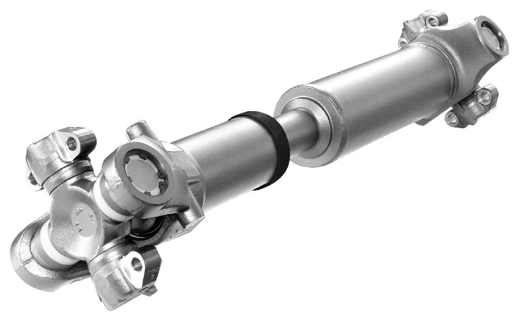
4 Drivelines Components TYPICAL DRIVELINE SYSTEM NOTE: Series shown are for illustration only. TRANSMISSION NON-SLIPCOU- PLINGSHAFTAS- SEMBLY STANDARD SLIP ASSEMBLY END YOKEOUTPUT WELD YOKE TUBING BEARING STUB CENTER BEARING KIT SPLINED YOKE SLIP YOKE SEAL STEEL SHROUD SPLINE PLUG TUBING WELD YOKE WELCH PLUG MAINTENANCE MANUAL 3
5 Drivelines TYPICAL DRIVELINE SYSTEM NOTE: Series shown are for illustration only. SHORT COUPLED SLIP ASSEMBLY END YOKE OUTPUT FRONT AXLE END YOKE OUTPUT SLIP YOKE SEAL SHAFT YOKE END YOKE OUTPUT REAR AXLE UNIVERSAL JOINT COMPONENTS BEARING CUPS TRUNNION BEARING CROSS 4 MAINTENANCE MANUAL
6 Introduction Description RPL Series Permalube (Non-Greaseable) The Meritor RPL Series Permalube non-greaseable driveline is permanently lubricated and sealed at the factory and does not require lubricants. Arrows on the wing bushings help you to correctly install the universal joint. Figure 2.1. FULL-ROUND a Figure 2.3 RPL SERIES PERMALUBE TM a EASY SERVICETM (1/2 ROUND) a Figure 2.1 Wing-Style Permalube The Meritor Wing-Style Permalube driveline requires lubrication of the slip yoke splines only. Figure 2.2. Figure 2.4 WING-STYLE a Figure 2.5 WING-STYLE PERMALUBE TM Figure 2.6 Figure 2.2 Full-Round, Easy Service, Wing-Style and 155R Series (Greaseable) Full-Round, Easy Service, Wing-Style and 155R greaseable drivelines require periodic lubrication of the universal joints and slip yoke splines. Figure 2.3, Figure 2.4, Figure 2.5 and Figure R SERIES b Figure 2.6 MAINTENANCE MANUAL 5
7 Inspection Hazard Alert Messages Read and observe all Warning and Caution hazard alert messages in this publication. They provide information that can help prevent serious personal injury, damage to components, or both. WARNING Check end yoke retaining nuts and bolts for looseness. Tighten loose fasteners to specification. Check the input and output shaft splines for wear and damage. Replace worn or damaged splines. Check for loose, missing or damaged driveline fasteners and parts. Tighten loose fasteners, and replace damaged and missing parts. Loose, damaged or missing parts can cause the driveline to separate from the vehicle. Serious personal injury and damage to components can result. To prevent serious eye injury, always wear safe eye protection when you perform vehicle maintenance or service. Only service a driveline when the engine is OFF. A rotating driveline can cause serious personal injury. Park the vehicle on a level surface. Block the wheels to prevent the vehicle from moving. Support the vehicle with safety stands. Do not work under a vehicle supported only by jacks. Jacks can slip and fall over. Serious personal injury and damage to components can result. Components Driveline 1. Park the vehicle on a level surface. Block the wheels to keep the vehicle from moving. Raise the vehicle so that the area you will service is off the ground. 2. Inspect the driveline at regular intervals. Loose end yokes, excessive radial movement, slip spline radial movement, bent driveline tubing or missing plugs in the slip yoke can damage universal joints and bearings. 3. Check the output and input end yokes on both the transmission and axle for axial looseness. Refer to the axle or transmission manufacturer s service instructions. If the output and input end yokes are loose: Disconnect the driveline. Tighten the end yoke retaining nut to the correct specification. Refer to the axle or transmission manufacturer s service instructions. 4. Inspect for worn universal joints. Apply vertical force of about 50 pounds (22.7 kg) to the driveline near the universal joints. If movement is greater than inch (0.152 mm): Replace the universal joint. 5. Use a dial indicator to examine the slip yoke spline for excessive radial movement. Radial movement between the slip yoke and the tube shaft must not exceed inches (0.432 mm). If the radial movement exceeds inch (0.432 mm): Replace the slip yoke and the tube shaft. 6. Inspect the driveline for damaged or bent tubing. Carefully remove contaminants, such as mud and road debris. End Yokes Perform the following procedures before you lubricate universal joints or slip yokes. If you lubricate these components before you inspect them, lubricant can cover wear, damage and looseness. 1. Do not lubricate components. Inspect all input and output end yoke retaining nuts and bolts for gaps between mating surfaces. If gaps are present: Refer to the transmission, axle or transfer case manufacturer s service instructions. 2. Use the following procedure to check all input and output end yokes for looseness. A. Hold the end yoke with both hands. B. Move the end yoke UP-AND-DOWN and SIDE-TO-SIDE. There shouldn t be any movement where the yoke connects to the input and output shafts. Figure a Figure MAINTENANCE MANUAL
8 Inspection If the input and output end yokes are loose: Disconnect the driveline. Tighten the end yoke retaining nut or bolt to the correct specification. Refer to the axle or transmission manufacturer for correct inspection and replacement procedures. If the input and output end yokes are not loose, check that the transmission output shaft and axle input shaft splines aren t loose at the end yoke: Hold the yoke with one hand and rotate it LEFT-TO-RIGHT while you check end play for radial looseness. Figure 3.1. If you find excessive radial looseness: Replace the end yoke, or input or output shafts, as necessary. 3. Inspect for worn, damaged, missing and loose parts. Replace as required. Refer to the appropriate sections in this manual for these procedures. WARNING Universal Joints WARNING Excessive looseness across the ends of the universal joint bearing cup assemblies can cause imbalance or vibration in the driveline assembly. Imbalance or vibration can cause component wear, which can result in separation of the driveline from the vehicle. Serious personal injury and damage to components can result. 1. Use the following procedure to check for looseness across the ends of the universal joint bearing cup assemblies and trunnions. A. Hold the INBOARD yoke on the driveline with both hands. B. Try to move the yoke UP-AND-DOWN and SIDE-TO-SIDE by applying at least 50 lb-ft (222.5 Nm) of force to the driveline near the universal joints. Figure 3.3. Use a fine-tooth file or an emery cloth to remove raised metal or fretting from yoke cross hole surfaces. Take care not to remove an excessive amount of metal. These conditions can damage the cross and bearing and cause the driveline to separate from the vehicle. Serious personal injury and damage to components can result. 4. Inspect all end yoke cross hole surfaces and bolt hole threads for damage. Remove raised metal or fretting with a fine-tooth file or emery cloth. Figure 3.2. If bolt hole threads are damaged: Replace the yoke a Figure 3.3 If movement is greater than inch (0.152 mm): Replace the universal joint. 2. Inspect all universal joint kits in the driveline assembly a Greaseable Universal Joints 1. Check that all grease fittings are installed. Replace missing or damaged fittings. Tighten them to 6 lb-ft (8 Nm). Figure Check for loose grease fittings. Tighten them to 6 lb-ft (8 Nm). Figure 3.2 MAINTENANCE MANUAL 7
9 Inspection Figure Inspect the center bearing rubber cushion for damage. If equipped, check that the deflectors are not rubbing against the rubber cushion. Verify that the rubber cushion is correctly seated in the metal bracket. If any of these conditions are evident: Replace the center bearing assembly. Figure 3.4 Center Bearings 1. Inspect all center bearing and end yoke midship nuts for gaps between the mating surfaces. Figure 3.5. If you can see gaps between the mating surfaces: Disconnect the driveline. Tighten the coupling yoke retaining nut to lb-ft ( Nm). Figure a a Self-Aligning Center Bearings A self-aligning center bearing accepts ± five degrees of angular misalignment. This helps to ensure that the hanger bearing is correctly aligned to the driveline under all operating conditions. Use the same service procedures for a self- -aligning center bearing as for a standard center bearing. You can identify a self-aligning center bearing by the bright gold color of the integral deflector. Deflectors are integral to a self-aligning center bearing, so separate deflectors are not required. Some vehicles manufactured after January 18, 2002, are equipped with self-aligning center bearings. Figure 3.7. If you replace a self-aligning center bearing on a vehicle manufactured after January 18, 2002: You must install a new self-aligning center bearing. Do not install an original-design bearing. Figure Inspect the center bearing bracket bolts for looseness. Figure 3.6. If the bolts are loose: Verify that the bracket is aligned correctly before you tighten the bolts. Tighten the center bearing bracket bolts. Refer to the vehicle manufacturer s procedures for the correct torque specification. CENTER BEARING a Figure 3.6 Figure a Figure MAINTENANCE MANUAL
10 Inspection Slip Yoke NOTE: Check a slip yoke for movement with the driveline installed and the vehicle on a level surface with its wheels on the ground. 1. Check that the vehicle is on a level surface with its wheels on the ground. The driveline should be installed. 2. Firmly mount a dial indicator with a magnetic base onto the slip yoke barrel next to the dust seal. Figure 3.8. You don t want the dial indicator to move when you check the slip yoke for looseness, or the measurement will not be correct a Figure 3.9 NECK OF SPLINE PLUG SLIP YOKE BARREL DUST SEAL 3/4 (19.05 MM) MAXIMUM a 5. Inspect the driveline for damage or bent tubing.if the driveline is damaged or bent: Replace the driveline. 6. If necessary, carefully remove mud or road debris from the driveline. 7. Inspect the slip yoke spline seal for grease leakage or seal damage. 8. Inspect for missing balance weights, damaged tubing or a missing welch plug at the slip yoke. Figure Extend the dial indicator arm from the base, so that it contacts the neck of the spline plug within 3/4-inch (19.05 mm) from the dust seal. Figure With your hands near the center of the driveline, move the slip yoke UP-AND-DOWN. Check the dial indicator measurement. Movement between the spline plug and slip yoke must not exceed inch (0.432 mm). Figure 3.9. If movement exceeds inch (0.432 mm): Components are worn or damaged. Replace as required. MAINTENANCE MANUAL 9
11 Inspection Permalube Drivelines Inspection and Maintenance Table A: RPL Series Permalube and Wing-Style Permalube Driveline Inspection Intervals and Procedures Mileage Intervals At initial inspection, or no more than 2,000 miles (3200 km) Every 25,000 miles ( km) Every 150,000 miles ( km) Procedures Verify that all bolts are tightened to lb-ft ( Nm). If you observe any of the following conditions, remove and replace components as needed. 1. Check for excessive looseness across the ends of the universal joint bearing cup assemblies and trunnions. Grip the driveline near the inboard yoke with both hands. Try to move the yoke vertically and horizontally. Movement in the universal joint relative to the inboard or outboard yokes must not exceed inch (0.152 mm). Figure Inspect the slip yoke spline seal for grease leakage or seal damage. 3. Inspect for missing balance weights, damaged tubing or a missing welch plug at the slip yoke. In addition to the 25,000-mile ( km) requirements: Use a dial indicator to inspect the slip splines for wear (backlash). Radial looseness between the slip yoke and the tube shaft must not exceed inch (0.432 mm). Figure a 3/4 (19.05 MM) MAXIMUM a Figure 3.10 Figure MAINTENANCE MANUAL
12 Inspection Universal Joint Capscrews WARNING Inspect RPL Series Permalube and Wing- -Style Permalube drivelines for loose or missing capscrews and lock washers. Loose or missing fasteners can allow the driveline to separate from the vehicle. Serious personal injury and damage to components can result. If fasteners are loose or missing: RPL Series Permalube drivelines: Install new capscrews with Dri-Loc patches. Wing-Style Permalube drivelines: Install new capscrews with Dri-Loc patches and secure the capscrews with lock washers. If capscrews are loose: Remove and discard loose capscrews. Replace them with new capscrews and lock washers. 2. Use a torque wrench to verify that capscrews are tightened to the correct specification. Refer to Section 11. Check End Play 1. Check the universal joint for end play. Apply force in an UP-AND-DOWN and SIDE-TO- -SIDE motion. The universal joint must not move in either direction. Figure There should be less than inch (0.152 mm) BACK-AND-FORTH motion of the universal joint. Figure If movement is greater than inch (0.152 mm): Replace the universal joint. Meritor recommends that you inspect RPL Series Permalube bearing cup capscrews and wing-style capscrews and lock washers at initial inspection, or no more than 2,000 miles (3200 km). RPL Series Permalube Drivelines 1. Check that capscrews are installed on all universal joint positions. RPL Series Permalube capscrews and Wing-Style Permalube capscrews are not interchangeable. If capscrews are missing: Check for damage to the universal joint and yoke. Replace damaged parts and missing capscrews. If capscrews are loose: Remove and discard loose capscrews. Replace them with new capscrews. 2. Use a torque wrench to verify that capscrews are tightened to lb-ft ( Nm) a Figure 3.12 Wing-Style Permalube Drivelines 1. Check that both capscrews and lock washers are installed on all universal joint positions. RPL Series Permalube capscrews and Wing-Style Permalube capscrews are not interchangeable. If capscrews and lock washers are missing: Check for damage to the universal joint and yoke. Replace damaged parts, capscrews and lock washers. Refer to Section a Figure 3.13 MAINTENANCE MANUAL 11
13 RPL Series Permalube CAUTION A broken weld strap can cause a wing bushing to rotate. When a bushing rotates, it s possible to assemble it into the yoke backward. To ensure correct assembly and prevent damage to components, you must insert both of the wing bushing s machined keyways into the yoke. 2. Replace the universal joint if it s loose or the weld strap is broken or missing. Hazard Alert Messages Read and observe all Warning and Caution hazard alert messages in this publication. They provide information that can help prevent serious personal injury, damage to components, or both. WARNING To prevent serious eye injury, always wear safe eye protection when you perform vehicle maintenance or service. Use a brass or leather mallet for assembly and disassembly procedures. Do not hit steel parts with a steel hammer. Pieces of a part can break off and cause serious personal injury. Only install the correct grade new bearing retainer bolts and stamped strap bolts. Do not reuse these parts. If the bearing retainer straps are damaged, install new retainers. Damaged and reused parts can affect driveline operation, which can cause the driveline to separate from the vehicle. Serious personal injury and damage to components can result. A driveline assembly can weigh more than 100 pounds (46 kilograms). Always use lifting devices and the correct procedures when you handle drivelines to prevent serious personal injury and damage to components. Removal Driveline WARNING Only service a driveline when the engine is OFF. A rotating driveline can cause serious personal injury. Park the vehicle on a level surface. Block the wheels to prevent the vehicle from moving. Support the vehicle with safety stands. Do not work under a vehicle supported only by jacks. Jacks can slip and fall over. Serious personal injury and damage to components can result. 1. Park the vehicle on a level surface. Block the wheels to keep the vehicle from moving. Raise the vehicle so that the area you will service is off the ground. Support the vehicle with safety stands. 2. Use a 12-point socket to loosen the four bolts (1/2 x 20-inch thread) located in the weld yoke end of the driveline. Figure 4.1. Figure 4.1 Figure MAINTENANCE MANUAL
14 RPL Series Permalube NOTE: Support the driveline when you remove it from the end yoke. 2. If necessary, use a brass drift and lightly tap the center of the bushing to assist in snap ring removal. Figure If necessary, use an appropriate tool to tap the wing bushing from the end yoke. Figure Repeat Step 2 through Step 4 to remove the opposite end of the driveline. Figure Repeat the previous steps on the other side of the yoke. Round Bushings Universal Joint Snap Ring Figure 4.3 NOTE: Use only the specified tools to remove the round bushings. Do not use the SPX Kent- -Moore yoke bearing cup installation tool (number J-44516) to remove the round bushings. Damage to the tool can result. NOTE: Refer to the Service Notes page on the front inside cover of this manual for information on how to obtain SPX Kent-Moore tools. 1. Use snap ring pliers (SPX Kent-Moore tool number J ) to remove the snap rings. Figure 4.4. SPX KENT-MOORE TOOL NUMBER J Use one of the following procedures to remove and install round bushings. Press, bridge and bearing cup receiver Universal joint press Universal joint puller WARNING Observe all warnings and cautions provided by the press manufacturer to avoid damage to components and serious personal injury. Figure 4.4 MAINTENANCE MANUAL 13
15 RPL Series Permalube Using a Press, Bridge and Bearing Cup Receiver 1. Use a press bridge (SPX ICM Kent-Moore tool number J ) and bearing cup bushing receiver (SPX Kent-Moore tool number J ). Figure 4.6. Refer to the Service Notes page on the front inside cover of this manual for information to obtain these tools. Figure 4.8 PRESS 4. Remove the universal joint from the yoke. BRIDGE SPX ICM TOOL NUMBER J BEARING CUP BUSHING RECEIVER SPX KENT MOORE TOOL NUMBER J Using a Universal Joint Press 1. Position a universal joint press (Tiger Tool number 10707). Figure 4.9. Refer to the Service Notes page on the front inside cover of this manual for information to obtain this tool. Figure Press DOWN until the first round bushing loosens. Figure 4.6. Remove the round bushing. Figure 4.7. UNIVERSAL JOINT PRESS TIGER TOOL NUMBER Figure 4.9 Figure Turn the screw on the tool CLOCKWISE until the round bushing loosens. 3. Turn the screw on the tool COUNTERCLO- CKWISE until you can remove the round bushing. 4. Turn over the universal joint. Repeat the procedure for the opposite side of the universal joint. 5. Remove the universal joint from the yoke. 3. Rotate the shaft 180 degrees. Repeat the procedure for the opposite side of the universal joint. Figure 4.8. Using a Universal Joint Puller 1. Position a universal joint puller (Tiger Tool number 10102). Refer to the Service Notes page on the front inside cover of this manual for information to obtain this tool. Figure MAINTENANCE MANUAL
16 RPL Series Permalube UNIVERSAL JOINT PRESS TIGER TOOL NUMBER Figure 4.12 Figure Turn the screw on the tool CLOCKWISE until the round bushing loosens. 3. Turn the screw on the tool COUNTERCLO- CKWISE and remove the round bushing. 4. Turn over the universal joint. Repeat the procedure for the opposite side of the universal joint. 5. Remove the universal joint from the yoke. 3. Mark the slip yoke and slip shaft sections to ensure that you reassemble them into their original positions. Figure Disassembly Figure 4.13 Slip Yoke 1. Use a brass or copper hammer and a drift to tap the shroud off the slip seal. Figure Pull the slip yoke and slip shaft sections apart. Figure HAMMER DRIFT WELD STRAP Figure 4.14 Figure Remove the seal. Figure Remove the shroud. Figure Use a screwdriver to pry the seal out of the groove in the slip yoke. Figure MAINTENANCE MANUAL 15
17 RPL Series Permalube Figure 4.18 Figure Use a brush to distribute lubricant on the splines. Figure Figure 4.16 Assembly Slip Yoke 1. Use an Allen wrench to remove the grease plug from the slip yoke before you assemble the slip yoke and spline shaft sections. Figure Install the new shroud. Figure Figure 4.19 Figure 4.17 Figure Use the grease packet supplied with the slip yoke to apply the entire amount of grease into the slip yoke. Figure Install the new seal onto the spline shaft neck. Ensure that the small diameter side fits onto the splines first. Figure MAINTENANCE MANUAL
18 RPL Series Permalube Figure 4.21 SMALL DIAMETER LARGE DIAMETER SHROUD Figure Align the slip yoke and spline shaft sections with the phasing marks you made on these sections during disassembly. Figure Figure Use a brass or copper hammer to tap the shroud over the seal. Push together the driveline sections. Figure 4.25 and Figure PHASING MARKS Figure 4.25 Figure Install the spline shaft into the slip yoke until the splines fully engage. Figure Snap the seal into the groove. Figure 4.23 and Figure Figure Use an Allen wrench to reinstall the grease plug. Figure Figure 4.23 Figure 4.27 MAINTENANCE MANUAL 17


19 RPL Series Permalube Installation Wing Bushings The previous design wing bushing did not have an interference boss. As a result, it was possible to insert the wing bushing into the yoke and install the pieces incorrectly. Figure WARNING If you do not correctly install the universal joint and end yoke, the bushings will not correctly seat in the yoke, which can cause the capscrews that secure the universal joint to fatigue under normal operating conditions. Serious personal injury and damage to components can result. INCORRECT BUSHING INSTALLATION CAUTION A broken weld strap can cause a wing bushing to rotate. When a bushing ROTATES, it s possible to assemble it INTO the yoke backward. To ensure correct assembly and prevent damage to components, you must install both of the wing bushing s interference bosses AWAY from the yoke. The new design wing bushing has interference bosses on the bushing. The bosses interfere with the end yoke if you attempt to install the wing bushing incorrectly. You must install the interference bosses away from the yoke. Figure Universal Joint CORRECT BUSHING INSTALLATION CAUTION c Figure 4.29 Do not use grease or anti-seize compound in the yoke ear bores. Damage to components can result. 1. Clean dirt and contamination from the slip yoke and weld yoke ear bores. Figure INTERFERENCE BOSS INCORRECT BUSHING INSTALLATION INTERFERENCE BOSS CORRECT BUSHING INSTALLATION b Figure MAINTENANCE MANUAL
20 RPL Series Permalube END YOKE At installation the wing bearing weld strap must face INBOARD. WELD YOKE CAPSCREWS (EIGHT TOTAL) SLIP YOKE At installationdirectional arrows face OUTBOARD (toward end yoke). UNIVERSAL JOINT CROSS Align yoke nib with square button on universal joint kit as shown. Install the universal joint kit by inserting both of the wing bearing s machined keyways into the yoke. Tap cups into place before you tighten capscrews. Strap must face AWAY from end yoke as shown Figure Install the universal joint into the yoke so that the wing bearing weld straps face INBOARD and the arrows point toward the end or coupling yokes. Figure WING BUSHINGS To correctly install the universal joint into the end yoke, the wing bushing weld strap must face INBOARD. Arrows must point TOWARD the end yoke. Figure 4.31 MAINTENANCE MANUAL 19
21 RPL Series Permalube CAUTION The universal joint is supplied with the correct amount of grease. Do not APPLY additional grease to the joint. Do not use grease or anti- -seize compound on the outside diameter of the cups, the cross bore holes of the yoke, or the yoke saddles. Damage to components can RESULT. NOTE: The deflector is preassembled onto the round bushing. 3. Verify that the plastic deflectors are attached to the round bushings. Figure WARNING Observe all warnings and cautions provided by the press manufacturer to avoid damage to components and serious personal injury. CAUTION Use an arbor press, universal joint press or yoke bearing cup installation TOOL to INSTALL the round bushing into the yoke. Do not use a hammer, which can loosen and damage components. NOTE: The SPX Kent-Moore press yoke bearing cup installation tool number J has a positive stop for correct installation. Refer to the Service Notes page on the front inside cover of this manual for information to obtain this tool. DEFLECTOR) Figure Use a press, yoke bearing cup installation tool (SPX Kent-Moore tool number J-44516) or universal joint press (Tiger Tool number 10707) to install the first round bushing slightly past the snap ring groove. When the bearing cup installation tool contacts the yoke, it is installed correctly. Figure 4.34, Figure 4.35 and Figure YOKE BEARING CUP INSTALLATION METHOD 4. Position the first round bushing onto the trunnion by threading the cross trunnion through the yoke bore. Figure YOKE BEARING CUP INSTALLA- TION TOOL NUM- BER J WING- BUSHING Figure 4.34 UNIVERSAL JOINT PRESS METHOD ROUND BUSHING Thread the crossthrough the yoke bore,then start the roundbushing on the trunnion. Figure 4.33 UNIVERSAL JOINT PRESS TOOLNUMBER Figure MAINTENANCE MANUAL
22 RPL Series Permalube YOKE BEARING CUP INSTALLA- TION TOOL TOOL NUMBER J PRESS METHOD PRESS 8. Use a press, yoke bearing cup installation tool (SPX Kent-Moore tool number J-44516) or universal joint press (Tiger Tool number 10707) to install the second round bushing slightly past the snap ring groove. Check that the bushing is aligned with the universal joint. Figure 4.34, Figure 4.35 and Figure CAUTION Figure 4.36 You must fully seat the snap ring INTO the snap ring groove TO AVOID damage to the driveline. CAUTION You must fully seat the snap ring INTO the snap ring groove to AVOID damage to the driveline. 9. Use snap ring pliers to install the second snap ring into the snap ring groove. Figure Use snap ring pliers to install the snap ring into the snap ring groove. Figure Fully seat the snap ring. WING BUSHING Figure Position the second bushing onto the trunnion by threading the cross through the yoke bore as shown. Figure Figure Strike the yoke ear with a brass or copper hammer to ensure that the universal joint moves freely. Figure Thread thetrunnionthrough the yokebore to pilot theround bushinginto the yoke. Move the joint with your handto ensure free movement. Figure 4.40 Figure 4.38 MAINTENANCE MANUAL 21
23 RPL Series Permalube Driveline WARNING If you do not correctly install the universal joint and end yoke, the bushings will not correctly seat in the yoke, which can cause the capscrews that secure the universal joint to fatigue under normal operating conditions. Serious personal injury and damage to components can result. You must position the wing bushing s machined keyway against the machined keyway of the end yoke ears when you install a universal joint. Ensure that the arrows stamped on the wing bushing point TOWARD the end yoke, and the universal joint weld strap faces the driveline and AWAY from the yoke. CAUTION A broken weld strap can cause a wing bushing to rotate. When a bushing ROTATES, it s possible to assemble it INTO the yoke backward. To ensure correct assembly and prevent damage to components, you must insert both of the wing bushing s machined keyways into the yoke. 2. If necessary, tap the universal joint with a brass or copper hammer to ensure it is fully seated. Figure YOKE NIBS Machined key way sare on this side. WELD STRAP Arrows indicate direction of installation. Figure Install the new capscrews. 4. Use a torque wrench to alternately tighten the capscrews to lb-ft ( Nm). Figure Before you install the capscrews, check that the universal joint is fully seated in the end yoke. The arrows on the wing bushing should point toward the coupling yoke. Figure Figure 4.43 Machined keywaysare on this side. Arrows towardcoupling yoke. WELD STRAP Figure MAINTENANCE MANUAL
24 Full-Round Hazard Alert Messages 4. Remove the second bearing cup. Figure 5.2. Read and observe all Warning and Caution hazard alert messages in this publication. They provide information that can help prevent serious personal injury, damage to components, or both. WARNING To prevent serious eye injury, always wear safe eye protection when you perform vehicle maintenance or service. Park the vehicle on a level surface. Block the wheels to prevent the vehicle from moving. Support the vehicle with safety stands. Do not work under a vehicle supported only by jacks. Jacks can slip and fall over. Serious personal injury and damage to components can result. Removal Driveline 1. Park the vehicle on a level surface. Block the wheels to keep the vehicle from moving. Raise the vehicle so that the area you will service is off the ground. Support the vehicle with safety stands. 2. Loosen and remove the capscrews from the end yoke bearing cups. 3. Remove the first bearing cup. If necessary, use a bearing puller to remove the bearing cup from the yoke bore. Figure 5.1 UNIVERSAL JOIN TPULLER TIGER TOOL NUMBER BUSHING Figure 5.2 NOTE: Support the driveline when you remove it from the end yoke. 5. Slide the yoke to one side until you can work a trunnion free from the yoke bore. 6. Slide the yoke in the OPPOSITE direction while removing the universal joint from the end yoke. 7. Repeat Step 2 to Step 6 to separate the slip yoke end of the driveline. Universal Joint 1. Loosen and remove the capscrews from the two remaining bearing cups on the yoke end of the driveline. 2. Remove the bearing cups. If necessary, use a commercial bearing puller to remove the bearing cups from the yoke bores. 3. Work the trunnions free of the yoke bores. Remove the universal joint cross from the weld yoke. 4. Repeat Step 1 to Step 3 to remove the universal joint cross from the slip yoke. Installation Universal Joint WARNING Figure 5.1 Use a brass or leather mallet for assembly and disassembly procedures. Do not hit steel parts with a steel hammer. Pieces of a part can break off and cause serious personal injury. MAINTENANCE MANUAL 23
25 Full-Round 1. Install the universal joint cross into the yoke. 2. Install the two bearing cups through the yoke bores and onto the universal joint cross trunnions. If necessary, use a copper or brass hammer to tap the bearing caps until they are fully seated. 3. Hand-tighten the capscrews through the bearing cover plate and into the slip yoke. 4. Use a torque wrench to alternately tighten the capscrews to the correct specifications. Refer to Table B. 5. Repeat Step 1 to Step 3 to install the universal joint cross into the weld yoke. 5. Install new capscrews and hand-tighten them through the bearing cover plate and into the yoke. 6. Repeat Step 2 to Step 5 to install the second bearing cup. If the cover plate will not seat flush against the yoke surface: Remove each bearing cup from the yoke bore. Check the bottom of each bearing cup. If you find a needle bearing, replace the bearing cup. 7. Use a torque wrench to alternately tighten the capscrews to correct specifications. Refer to Table B. Figure 5.5. Driveline 1. Wipe off the end yoke bearing bores. Insert the trunnion through the yoke bore. 2. Check the bearing cup to ensure that the needle bearings are in place. Replace the bearing cup when the needle bearings are missing or out of place. 3. Hold the cross. Use a copper or brass hammer to lightly tap the bearing cup completely into the yoke bore. Figure 5.3. Figure 5.5 Table B: Torque Specifications Full- -Round Driveline Series A Inches (mm) Thread Size Inches Torque Specs lb-ft (Nm) 16N 5.31 (134.87) 5/ (35-47) Figure N 6.09 (154.69) 3/ (51-65) 4. Align the cover plate holes and the yoke ear. Figure 5.4. Install the bearing cover plate flush against the milled surface of the yoke. 176N 7.00 (177.8) 3/ (51-65) 18N 7.55 (191.77) 3/ (51-65) Figure MAINTENANCE MANUAL
26 Full-Round A YOKE GAUGE TOOL Identifies driveline series A dimension across yoke ears determines end yoke/universal joint series a Figure 5.7 Lubrication Universal Joint After installation into the end yokes, lubricate the universal joints at the grease fitting until grease flows from the bearing cup seals on all four trunnions. Use Meritor grease specification O-634-B, NLGI Grade 2 with EP additive. Figure 5.6. If grease does not purge from the seals: Follow the steps below. B. Loosen the bearing cup capscrews. Add grease until grease purges from the seals. If grease still does not purge from all four trunnion seals: Remove the universal joint and correct the problem. If you cannot determine the problem: Replace the universal joint. C.Tighten the capscrews. Refer to Table B. Slip Yoke Splines NOTE: When you lubricate a slip yoke, the splined shaft can be either fully extended or fully collapsed. New grease must flow at all four seals After installation, add Meritor specification O-634-B, NLGI Grade 2 with EP additive to the slip yoke grease fitting. Six to eight pumps or approximately one oz (28 grams) is sufficient to lubricate the splines. Figure 5.8. Shown without end yokes for clarity. Figure 5.6 A. Move the assembly UP-AND-DOWN or SI- DE-TO-SIDE while you apply grease gun pressure. Figure 5.7. Figure 5.8 MAINTENANCE MANUAL 25
27 Wing-Style Permalube Hazard Alert Messages Read and observe all Warning and Caution hazard alert messages in this publication. They provide information that can help prevent serious personal injury, damage to components, or both. WARNING To prevent serious eye injury, always wear safe eye protection when you perform vehicle maintenance or service. Use a brass or copper hammer to seat bearing cups into yoke bores. Do not use a steel hammer, which can cause the yoke or bearing cup to crack and break off. Serious personal injury and damage to the trunnion, yoke or bearing cup can result. Only service a driveline when the engine is OFF. A rotating driveline can cause serious personal injury. Universal Joint NOTE: Wing-style universal joints are permanently assembled. Welded steel straps attach the bearing cups to the trunnion to help ensure that the universal joint fits correctly into the mating yokes. Do not cut or remove the welded straps from the universal joint kits. 1. Loosen and remove the four capscrews retaining the universal joint cross to the weld yoke. 2. Loosen and remove the four capscrews retaining the universal joint cross to the slip yoke. Figure 6.1. Removal Driveline WARNING Park the vehicle on a level surface. Block the wheels to prevent the vehicle from moving. Support the vehicle with safety stands. Do not work under a vehicle supported only by jacks. Jacks can slip and fall over. Serious personal injury and damage to components can result. 1. Park the vehicle on a level surface. Block the wheels to keep the vehicle from moving. Raise the vehicle so that the area you will service is off the ground. Support the vehicle with safety stands. 2. Loosen and remove the four capscrews from the weld yoke end of the driveline. Support the weld yoke end, and separate it from the end yoke. 3. Loosen and remove the four capscrews from the slip yoke end of the driveline. Support the slip yoke end, and separate it from the vehicle. Installation Figure 6.1 Universal Joint 1. Tap the bearing cups lightly with a brass or copper hammer to seat the bearing cups into the yoke pilot. NOTE: Capscrews have a lock patch and can be hand-tightened only two or three threads. 2. Install new capscrews and lock washers. Figure 6.2. Refer to Table C. 3. Hand-tighten the capscrews to the yoke pilot. 4. Use a torque wrench to alternately tighten the capscrews to correct specifications. Figure 6.2. Refer to Table C. 26 MAINTENANCE MANUAL
28 Wing-Style Permalube Lubrication Universal Joint Wing-style universal joints can be greaseable or non-greaseable. Non-greaseable Permalube universal joints do not have grease fittings. Figure 6.2 Table C: Replacement Parts and Torque Specifications Drivelines Name Description Wing-Style Permalube Capscrew Jam Nut 1/2-20 x 2-1/2º 1/2-20 x 1-1/2º 3/8-24 7/ /2º H.D. Torque Specs lb-ft (Nm) ( ) (54-74) (85-112) (85-112) Driveline NOTE: You may install either the slip yoke or weld yoke driveline end first when following the instructions below. After you install one driveline end, repeat these steps to install the opposite end of the driveline. 1. Support the driveline. 2. Tap the bearing cups lightly with a brass or copper hammer to seat the bearing cups into the end yoke. 3. Install the four capscrews and lock washers that attach the universal cross to the end yoke. Figure 6.1. NOTE: Capscrews have a lock patch and can be hand-tightened only two or three threads. 4. Hand-tighten the capscrews to the yoke pilot. 5. Use a torque wrench to alternately tighten the capscrews to Meritor s driveline torque specifications. Refer to Table C and Figure Repeat Step 1 to Step 5 to install the opposite driveline end. Wing-Style Permalube Universal Joints (Non-Greaseable) Wing-Style Permalube universal joints are permanently lubricated with grease developed with specific wear and temperature properties. However, you must periodically lubricate the slip yoke splines. Refer to Table G and Slip Yoke Splines for specifications and maintenance procedures. Wing-Style Universal Joints (Greaseable) Wing-style greaseable universal joints have grease fittings and are not permanently lubricated. Refer to Table G. To lubricate greaseable universal joints, follow the procedures provided for the Full-Round driveline in Section 5. Slip Yoke Splines CAUTION Do not remove the grease plugs from the cross in an ATTEMPT TO add additional grease. Damage TO the universal joint can result. NOTE: When you lubricate a slip yoke, the splined shaft can be either fully extended or fully collapsed. The slip yoke splines are not permanently lubricated and must be greased periodically. Add Meritor specification O-634-B, NLGI Grade 2 with EP additive to the slip yoke grease fitting. Six to eight pumps or approximately one oz (28 grams) is sufficient to lube the splines. Figure 6.3. Figure 6.3 MAINTENANCE MANUAL 27
29 Easy Service Hazard Alert Messages Read and observe all Warning and Caution hazard alert messages in this publication. They provide information that can help prevent serious personal injury, damage to components, or both. WARNING To prevent serious eye injury, always wear safe eye protection when you perform vehicle maintenance or service. Removal Driveline WARNING Only service a driveline when the engine is OFF. A rotating driveline can cause serious personal injury. Park the vehicle on a level surface. Block the wheels to prevent the vehicle from moving. Support the vehicle with safety stands. Do not work under a vehicle supported only by jacks. Jacks can slip and fall over. Serious personal injury and damage to components can result. Universal Joint 1. Loosen and remove the capscrews from the two bearing cups on the weld yoke end of the driveline. 2. Remove the bearing cups. If necessary, use a bearing puller to remove the bearing cups from the yoke bores. 3. Work the trunnions free of the yoke bores. Remove the universal joint cross from the weld yoke. 4. Repeat Step 1 to Step 3 to remove the universal joint cross from the slip yoke. Installation Universal Joint WARNING Use a brass or leather mallet for assembly and disassembly procedures. Do not hit steel parts with a steel hammer. Pieces of a part can break off and cause serious personal injury. CAUTION Do not SEAT the bearing cups into the yoke saddle by tightening down the bearing straps and capscrews. Uneven load distribution, yoke bearing ROTATION, and damage to the straps and yoke nibs can result. NOTE: To help ensure maximum driveline performance, do not apply lubricant, grease, anti- -seize compound, etc., to the yoke saddles. 1. Install the universal joint cross into the yoke. Always use new bolts and straps. NOTE: For easier installation, do not remove the wire that fastens the bearing cups to the universal joint trunnion. 2. Install the bearing cups through the yoke bores and onto the universal joint cross trunnions. 3. Tap the bearing cup lightly with a leather or rubber mallet to seat the bearing cups into the yoke saddle. NOTE: Capscrews have a lock patch and can be hand-tightened only two or three threads. 4. Hand-tighten the bearing capscrews. Use a torque wrench to tighten the capscrews to the specified torque. Refer to Table D. 28 MAINTENANCE MANUAL
30 Easy Service Driveline 1. Wipe off the yoke saddle. 2. Support the driveline. Install the bearing straps and capscrews onto the slip yoke end of the driveline. NOTE: Capscrews have a lock patch and can be hand-tightened only two or three threads. 3. Hand-tighten the capscrews through the bearing strap into the yoke. 4. Use a torque wrench to alternately tighten the capscrews to Meritor s driveline torque specification. Refer to Table D. Figure Repeat Step 1 through Step 3 to attach the weld yoke end of the driveline to the vehicle. A dimension between yoke ears determines end yoke/ universal joint series. Lubrication A YOKE GAUGE TOOL Identifies driveline series Universal Joint Lubricate the universal joints at the grease fitting until grease flows from the bearing cup seals on all four trunnions. Use a grease that meets Meritor specification O-634-B, NLGI Grade 2 with EP additive. Figure 7.2. Figure 7.1 Table D: Torque Specifications Easy Service Driveline Series 155T 16T A Inches (mm) 4.97 (126.24) 5.31 (134.87) Thread Size Inches 3/8-24 3/8-24 Torque Specs lb-ft (Nm) (54-81) (61-81) If grease does not purge from all four trunnion seals: Follow the steps below. A. Move the assembly UP-AND-DOWN or SIDE-TO-SIDE while you apply grease gun pressure. Figure 7.3. B. Loosen the bearing cup capscrews. Add grease until grease purges from the four seals. C.Tighten the bearing cup capscrews after grease purges. If grease still does not purge from all four trunnion seals: Remove the universal joint and correct the problem. If you cannot, replace the universal joint. New grease mustflow at all four seals. 17T 6.19 (157.23) 1/ ( ) 176T 7.09 (180.08) 1/ ( ) Figure T 7.63 (193.8) 1/ ( ) MAINTENANCE MANUAL 29
31 Easy Service Figure 7.3 Slip Yoke Splines NOTE: When you lubricate a slip yoke, the splined shaft can be either fully extended or fully collapsed. Add a grease that meets Meritor specification O-634-B, NLGI Grade 2 with EP additive, to the slip yoke grease fitting. Six to eight pumps or approximately one oz (28 grams) is sufficient to lube the splines. Figure 7.4. Figure MAINTENANCE MANUAL
32 155R Series Slip Drive Shaft Assembly Description 155R Series Drive Shaft Configurations The 155R Series offers two drive shaft configurations: Standard slip Outboard slip Both configurations are available in two-piece and three-piece drivelines. Standard Slip Drive Shaft With the standard slip drive shaft assembly, the splined shaft points forward in the vehicle. Figure 8.1. FRONT REAR STANDARDSLIP SHAFTASSEMBLY c Figure 8.1 Outboard Slip Drive Shaft Assembly The splined shaft points to the rear of the vehicle with the outboard slip drive shaft assembly. A center bearing supports the forward section of the drive shaft assembly. Figure 8.2. FRONT REAR OUTBOARD SLIP SHAFT ASSEMBLY b Figure 8.2 MAINTENANCE MANUAL 31
33 155R Series Slip Drive Shaft Assembly Two-Piece Drivelines A two-piece driveline is comprised of a non-slip coupling shaft followed by either a standard slip or reverse slip drive shaft assembly. The non-slip coupling shaft is always positioned in front of the slip shaft. Figure 8.3 and Figure 8.4. TWO-SHAFT STANDARD SLIP TRANSMISSION NON-SLIP COU- PLING SHAFT ASSEMBLY STANDARD SLIP ASSEMBLY END YOKE OUTPUT WELD YOKE TUBING BEARING STUB CENTER BEARING KIT SPLINED YOKE SLIP YOKE SEAL SPLINE PLUG TUBING WELD YOKE WELCH PLUG a Figure MAINTENANCE MANUAL
34 155R Series Slip Drive Shaft Assembly TWO-SHAFT OUTBOARD SLIP TRANSMISSION OUTBOARD SLIP SHAFT ASSEMBLY DOGBONE SHAFT ASSEMBLY WELD YOKE END YOKE OUTPUT TUBING SPLINE PLUG CENTER BEARING KIT SEAL SLIP YOKE WELD YOKE TUBING WELD YOKE STRAP CENTER BEARING KIT STRAP b Figure 8.4 MAINTENANCE MANUAL 33
35 155R Series Slip Drive Shaft Assembly Three-Piece Drivelines A three-piece driveline is comprised of two non-slip coupling shafts followed by either a standard slip or reverse slip drive shaft assembly. The non-slip coupling shafts are always positioned in front of the slip shaft. Figure 8.5 and Figure 8.6. THREE-SHAFT STANDARD SLIP TRANSMISSION NON-SLIP COU- PLING SHAFT ASSEMBLIES STANDARD SLIP ASSEMBLY END YOKE OUTPUT WELD YOKE TUBING BEARING STUB CENTER BEARING KIT SPLINED YOKE SLIP YOKE SEAL SPLINE PLUG TUBING WELD YOKE WELCH PLUG a Figure MAINTENANCE MANUAL
36 155R Series Slip Drive Shaft Assembly THREE-SHAFT OUTBOARD SLIP TRANSMISSION NON-SLIP COUPLING SHAFT ASSEMBLIES OUTBOARD SLIP SHAFT ASSEMBLY DOGBONE SHAFT ASSEMBLY END YOKE OUTPUT WELD YOKE TUBING BEARING STUB CENTER BEARING KIT SPLINE YOKE CENTER BEARING KIT WELD YOKE TUBING WELD YOKE WELD YOKE TUBING SPLINE PLUG SEAL SLIP YOKE b STRAP CENTER BEARING KIT STRAP Figure 8.6 MAINTENANCE MANUAL 35
37 155R Series Slip Drive Shaft Assembly Hazard Alert Messages Read and observe all Warning and Caution hazard alert messages in this publication. They provide information that can help prevent serious personal injury, damage to components, or both. WARNING To prevent serious eye injury, always wear safe eye protection when you perform vehicle maintenance or service. Universal Joint Snap Ring NOTE: Refer to the Service Notes page on the front inside cover of this manual for information on how to obtain SPX Kent-Moore tools. 1. Use snap ring pliers to remove the snap rings. Figure 8.7. Removal Driveline SPX KENT-MOORE TOOL NUMBER J WARNING Only service a driveline when the engine is OFF. A rotating driveline can cause serious personal injury. Park the vehicle on a level surface. Block the wheels to prevent the vehicle from moving. Support the vehicle with safety stands. Do not work under a vehicle supported only by jacks. Jacks can slip and fall over. Serious personal injury and damage to components can result. Figure If necessary, use a brass drift and lightly tap the center of the bushing to assist in snap ring removal. Figure Park the vehicle on a level surface. Block the wheels to keep the vehicle from moving. Raise the vehicle so that the area you will service is off the ground. Support the vehicle with safety stands. 2. Loosen and remove the capscrews and bearing straps from the weld yoke end of the driveline. Support the weld yoke end and separate it from the end yoke. 3. Loosen and remove the capscrews and bearing straps from the slip yoke end of the driveline. Support the slip yoke end and separate it from the vehicle. Figure Repeat the previous steps on the other side of the yoke. 36 MAINTENANCE MANUAL
38 155R Series Slip Drive Shaft Assembly Round Bushings NOTE: Use only the appropriate tools to remove the round bushings. Do not use the SPX Kent-Moore yoke bearing cup installation tool (number J-44516) to remove the round bushings. Damage to the tool can result. Use one of the following procedures to remove and install round bushings. Press, bridge and bearing cup receiver Universal joint press Universal joint puller Figure Rotate the shaft 180 degrees. Repeat the procedure for the opposite side of the universal joint. Figure WARNING Observe all warnings and cautions provided by the press manufacturer to avoid damage to components and serious personal injury. Using a Press, Bridge and Bearing Cup Receiver 1. Place the universal joint in a suitable press bridge and bearing cup bushing receiver. Figure 8.9. Refer to the Service Notes page on the front inside cover of this manual for information to obtain these tools. Figure Remove the universal joint from the yoke. BRIDGE PRESS Using a Universal Joint Press 1. Position the universal joint in a suitable universal joint press. Figure Refer to the Service Notes page on the front inside cover of this manual for information to obtain this tool. BEARING CUP BUSHING RECEIVER c Figure 8.9 UNIVERSAL JOINT PRESS 2. Press DOWN until the first round bushing loosens. Figure 8.9. Remove the round bushing. Figure c Figure 8.12 MAINTENANCE MANUAL 37
39 155R Series Slip Drive Shaft Assembly 2. Turn the screw on the tool CLOCKWISE until the bushing loosens. 3. Turn the screw on the tool COUNTERCLO- CKWISE until you can remove the bushing. 4. Turn over the universal joint. Repeat the procedure for the opposite side of the universal joint. 5. Remove the universal joint from the yoke. Using a Universal Joint Puller 1. Position the universal joint in a suitable universal joint puller. Refer to the Service Notes page on the front inside cover of this manual for information to obtain this tool. Figure Figure Pull the slip yoke and slip shaft sections apart. Figure UNIVERSAL JOINT PULLER BUSHING c Figure Turn the screw on the tool CLOCKWISE until the bushing loosens. 3. Turn the screw on the tool COUNTERCLO- CKWISE and remove the bushing. 4. Turn over the universal joint. Repeat the procedure for the opposite side of the universal joint. 5. Remove the universal joint from the yoke. Figure Remove the seal from the slip shaft. Figure Disassembly Standard Slip Configuration 1. Mark the slip yoke and slip shaft sections to ensure that you reassemble them into their original positions. Figure Figure MAINTENANCE MANUAL
40 155R Series Slip Drive Shaft Assembly Outboard Slip Configuration 1. Mark the slip yoke and slip shaft sections to ensure that you reassemble them into their original positions. Figure Three-Piece Standard/Outboard Slip Driveline To disassemble the three-piece standard or outboard slip driveline, refer to the disassembly procedures for the standard slip and outboard slip configurations on the preceding pages. Assembly Figure 8.17 Standard Slip Configuration 1. Remove the grease fittings from the slip yoke before you assemble the slip yoke and spline shaft sections. 2. Use the grease packet supplied with the slip yoke to apply the entire amount of grease into the slip yoke. Figure Pull the slip yoke and slip shaft sections apart. Figure Figure Remove the seal from the slip shaft. Figure Figure Use a brush to distribute lubricant on the splines. Figure Figure 8.19 Figure 8.21 MAINTENANCE MANUAL 39
41 155R Series Slip Drive Shaft Assembly 4. Install the new seal onto the spline shaft neck. Ensure that the small diameter side fits onto the splines first. Figure Use a brass or copper hammer to tap the shroud over the seal. Push together the driveline sections. Figure 8.25 and Figure SMALL DIAMETER LARGE DIAMETER Figure 8.22 Figure Align the slip yoke and spline shaft sections with the phasing marks you made on these sections during disassembly. Figure PHASING MARKS Figure Reinstall the grease fittings. Figure Install the spline shaft into the slip yoke until the splines fully engage. Figure Snap the seal into the groove. Figure Installation Universal Joint CAUTION Do not use grease or anti-seize compound in the yoke ear bores. Damage to components can resultz. 1. Clean dirt and contamination from the slip yoke and weld yoke ear bores. Figure 8.24 NOTE: The deflector is preassembled onto the bushing. 40 MAINTENANCE MANUAL
42 155R Series Slip Drive Shaft Assembly 2. Verify that the plastic deflectors are attached to the bushings. Figure Use an appropriate press, yoke bearing cup installation tool or universal joint press to install the first bushing slightly past the snap ring groove. When the bearing cup installation tool contacts the yoke, it is installed correctly. Figure 8.29, Figure 8.30 and Figure YOKE BEARING CUP INSTALLATION METHOD DEFLECTOR YOKE BEARING CUP INSTALLATION Figure Position the first bushing onto the trunnion by threading the cross trunnion through the yoke bore. Figure Installing the Bushing c Figure 8.29 UNIVERSAL JOINT PRESS METHOD Thread the cross through the yoke bore,then start the bushing on the trunnion. Figure 8.28 UNIVERSAL JOINT PRESS WARNING Observe all warnings and cautions provided by the press manufacturer to avoid damage to components and serious personal injury. CAUTION Use an arbor press, universal joint press or yoke bearing cup installation TOOL to INSTALL the round bushing into the yoke. Do not use a hammer, which can loosen and damage components. Installing the Bushing YOKE BEARING CUP INSTALLATION TOOL Installing the Bushing PRESS METHOD c Figure 8.30 PRESS c Figure 8.31 MAINTENANCE MANUAL 41
43 155R Series Slip Drive Shaft Assembly CAUTION You must fully seat the snap ring INTO the snap ring groove to AVOID damage to the driveline. 8. Use snap ring pliers to install the second snap ring into the snap ring groove. Figure Use snap ring pliers to install the snap ring into the snap ring groove. Figure Fully seat the snap ring. Figure Strike the yoke ear with a brass or copper hammer to ensure that the universal joint moves freely. Figure Figure Position the second bushing onto the trunnion by threading the cross through the yoke bore as shown. Figure Thread thetrunnion through the yoke bore to pilot the bushing into the yoke. Move the joint with your hand to ensure free movement. Figure 8.35 Driveline 1. Wipe off the yoke saddle. 2. Support the driveline. Install the bearing straps and capscrews onto the slip yoke end of the driveline. Figure Use an appropriate press, yoke bearing cup installation tool or universal joint press to install the second bushing slightly past the snap ring groove. Check that the bushing is aligned with the universal joint. Figure 8.29, Figure 8.30 and Figure CAUTION You must fully seat the snap ring into the snap ring groove to avoid damage to the driveline. NOTE: Capscrews have a lock patch and can be hand-tightened only two or three threads. 3. Hand-tighten the capscrews through the bearing strap into the yoke. 4. Use a torque wrench to alternately tighten the capscrews to Meritor s driveline torque specification. Figure MAINTENANCE MANUAL
44 155R Series Slip Drive Shaft Assembly Figure 8.36 A. Move the assembly UP-AND-DOWN or SI- DE-TO-SIDE while you apply grease gun pressure. B. Loosen the bearing cup capscrews. Add grease until grease purges from the four seals. C.Tighten the bearing cup capscrews after grease purges. If grease still does not purge from all four trunnion seals: Remove the universal joint and correct the problem. If you cannot, replace the universal joint. 5. Repeat Step 1 to Step 3 to attach the weld yoke end of the driveline to the vehicle. Lubrication Universal Joint Lubricate the universal joints at the grease fitting until grease flows from the bearing cup seals on all four trunnions. Use a grease that meets Meritor specification O-634-B, NLGI Grade 2 with EP additive. Figure Slip Yoke Splines Add a grease that meets Meritor specification O-634-B, NLGI Grade 2 with EP additive, to the slip yoke grease fittings. Six to eight pumps or approximately one oz (28 grams) is sufficient to lube the splines. Figure If grease does not purge from all four trunnion seals: Follow the steps below. Figure 8.38 New grease must flow at all four seals. Figure 8.37 MAINTENANCE MANUAL 43


45 Center Bearing Removal and Installation Hazard Alert Messages Read and observe all Warning and Caution hazard alert messages in this publication. They provide information that can help prevent serious personal injury, damage to components, or both. ORIGINAL STYLE INSIDE DIAMETER WARNING To prevent serious eye injury, always wear safe eye protection when you perform vehicle maintenance or service. Do not use a steel hammer to seat bearing cups into yoke bores. A steel hammer can cause the yoke or bearing cup to crack and break off. Serious personal injury and damage to the trunnion, yoke or bearing cup can result. Only install the correct grade new bearing retainer bolts and stamped strap bolts. Do not reuse these parts. If the bearing retainer straps are damaged, install new retainers. Damaged and reused parts can affect driveline operation, which can cause the driveline to separate from the vehicle. Serious personal injury and damage to components can result. A driveline assembly can weigh more than 100 pounds (46 kilograms). Always use lifting devices and the correct procedures when you handle drivelines to prevent serious personal injury and damage to components. Deflectors no longer required. CUSHION NOT SLOTTED AT BASE 2 INSIDE DIAMETER CUSHION NOT SLOTTED AT BASE CURRENT STYLE GOLD TONE INSIDE DIAMETER Overview SLOTTED RUBBER CUSHION AT BASE The Procedures in This Section Apply to All Meritor Drivelines The center bearing removal and installation procedures in this section apply to Meritor RPL Permalube, Wing-Style Permalube, Easy Service, Full-Round and 155R drivelines. Deflectors no longer required. GOLD TONE 2 INSIDE DIAMETER Self-Aligning Center Bearings Some vehicles manufactured after January 18, 2002, are equipped with self-aligning center bearings. Deflectors are integral to a self-aligning center bearing, so separate deflectors are not required. You can identify a self-aligning center bearing by the bright gold color of the integral deflector. Figure 9.1. SLOTTED RUBBER CUSHION AT BASE Figure MAINTENANCE MANUAL


46 Center Bearing Removal and Installation Both the original and current designs use external waterproofing grease. The external waterproofing grease is displaced by centrifugal force, which can give the impression of leakage under normal conditions. Normal leakage is shown in the next two illustrations. This condition does not require center bearing replacement. Figure 9.2 and Figure 9.3. Removal Coupling Shaft 1. Ensure that the support strap is in the correct position to support the weight of the driveline. 2. Remove the center bearing bracket bolts. Figure 9.4. Figure 9.4 Figure Remove the universal joint from the coupling yoke. Discard the universal joint mounting bolts. If it s necessary to unseat the bearing cup assemblies: Use a rubber hammer to tap on the yoke or bearing cup. Once the coupling shaft is free, remove it from the support straps and move the driveline to a workbench. For driveline assemblies with more than two coupling shafts: Repeat Step 1 to Step 3 as necessary. Place the support straps on the additional coupling shafts. Disassembly Figure 9.3 The actual bearing grease is contained within the assembly by seals. This waterproofing grease leakage was not visible on the original-design center bearing due to the deflectors. A self-aligning center bearing accepts ± five degrees of angular misalignment. This helps to ensure that the hanger bearing is correctly aligned to the driveline under all operating conditions. The cushion on the self-aligning center bearing is loose by design. The looseness allows the self-aligning movement. MAINTENANCE MANUAL Coupling Yoke and Coupling Shaft WARNING Always replace a loose or damaged coupling yoke. Only install a new coupling shaft yoke nut. Do not reuse this part. A loose or damaged coupling yoke, or a reused yoke nut, can affect driveline performance and cause the driveline to separate from the vehicle. Serious personal injury and damage to components can result. 45
47 Center Bearing Removal and Installation 1. Remove the coupling shaft yoke nut. Discard the nut. Inspect the yoke washer. You can reuse the washer if it s not damaged. Figure 9.5. If the yoke washer is damaged: Discard the washer and replace it with a new one. Figure 9.7 WARNING Figure 9.5 Always reassemble a driveline according to the vehicle s original phasing type. A driveline that is not balanced correctly can affect driveline performance and cause the driveline to separate from the vehicle. Serious personal injury and damage to components can result. 2. Mark the end yoke counterbore to the coupling shaft nose. This will help you to reassemble the center bearing end yoke in its original phased position. Figure 9.6. PHASING MARKS 4. Remove the coupling shaft with the center bearing. Remove the coupling yoke, then the center bearing. If it s necessary to unseat the cup assemblies: Use a rubber hammer to tap on the yoke or bearing cup. Once the coupling shaft is free, remove it from the support straps. Move the coupling shaft to a workbench area. CAUTION The center bearing end yoke has a press fit. Use a puller TOOL TO remove it from the driveline. Do not use a hammer. Damage TO components can result. 5. Place the driveline on a workbench. Use a puller to remove the center bearing end yoke. Do not use a hammer. Follow the puller tool manufacturer s instructions. Figure 9.8. If the yoke is loose enough to remove by hand: Replace the entire coupling shaft. Figure Remove the center bearing bracket bolts. Figure 9.7. Allow the coupling shaft to rest on the support strap. Figure MAINTENANCE MANUAL
48 6. Inspect the center bearing end yoke splines. If the splines are damaged or missing, or the yoke is cracked: Replace the yoke. 7. Inspect the coupling shaft splines and threads. If the splines or threads are damaged or missing: Replace the entire coupling shaft. Center Bearing Removal and Installation Center Bearing 1. Remove and discard the center bearing bracket. Figure 9.9 CENTER BEARING BRACKET Figure Inspect the coupling shaft for wear on the bearing diameter. If the coupling shaft is damaged from a seized bearing: Replace the entire coupling shaft. Figure BEARING DIAMETER Figure Remove and discard the rubber cushion. Figure Figure 9.12 NOTE: Deflectors are integral to a self-aligning center bearing, so separate deflectors are not required. 5. Remove both deflectors, if equipped. Install a new center bearing, deflectors, if necessary, and coupling yoke. Figure Use a puller to remove the bearing assembly from the coupling shaft. Follow the puller tool manufacturer s instructions. Discard the center bearing. Figure Installation Deflectors 1. Wipe the center bearing support surface with a fine emery cloth. NOTE: Deflectors are integral to a self-aligning center bearing, so separate deflectors are not required. MAINTENANCE MANUAL 47
49 Center Bearing Removal and Installation 2. If necessary, install a new deflector on the coupling shaft. To avoid damaging the deflector, use a section of tubing and a brass hammer to seat the deflector. Verify that the deflector is completely seated against the center bearing support shoulder. Figure Figure 9.15 Figure 9.13 Center Bearing NOTE: Deflectors are integral to a self-aligning center bearing, so separate deflectors are not required. 5. Use a rubber hammer to tap the yoke onto the coupling shaft splines. The phasing marks on the driveline must be aligned. Figure 9.6. Continue to tap the yoke until it is completely seated against the center bearing. Do not use the nut to draw the yoke down. 6. Install a washer and a new coupling shaft yoke nut. Tighten the nut to lb-ft ( Nm). 1. Install deflectors, if included in the center bearing kit. Otherwise, deflectors are not required. 2. Carefully align the new center bearing assembly with the machined surface of the coupling shaft. Use your hands to push the center bearing onto the coupling shaft. Figure Coupling Shaft 1. Verify that the support straps are in the correct position to support the weight of the driveline. 2. Align the center bearing bracket with the frame support. 3. Install bearing spacers, if necessary, to return the bearing bracket to its original position. Figure Figure Use a punch and brass hammer to install the bearing. 4. If a deflector is required, use a section of tubing and a brass hammer to press the deflector remaining onto the end yoke to avoid damaging the deflector. Figure a Figure Install the center bearing bracket bolts. Tighten them to the vehicle manufacturer s specification. 48 MAINTENANCE MANUAL
50 Lubrication Hazard Alert Messages Read and observe all Warning and Caution hazard alert messages in this publication. They provide information that can help prevent serious personal injury, damage to components, or both. WARNING To prevent serious eye injury, always wear safe eye protection when you perform vehicle maintenance or service. Non-Greaseable Drivelines The RPL Series Permalube non-greaseable driveline is completely lubricated and sealed at the factory and does not require lubrication. Figure RPL SERIES PERMALUBE NON-GREASEABLE Maintenance Greaseable Drivelines The Full-Round, Easy Service, Wing-Style and 155R greaseable drivelines require periodic lubrication of the universal joints and slip yoke splines. Figure 10.1 and Figure FULL-ROUND, EASY SERVICE AND 155R Figure 10.3 The Wing-Style Permalube non-greaseable driveline requires lubrication of the slip yoke splines ONLY. Figure WING-STYLE NON-GREASEABLE LUBE POINT LUBE POINT LUBE POINT Figure 10.1 LUBE POINT Figure 10.4 WING-STYLE GREASEABLE Inspection LUBE POINT Figure 10.2 LUBE POINT LUBE POINT Figure 10.2 Driveline 1. Inspect the Full-Round, Easy Service, Wing-Style and 155R greaseable drivelines for wear and damage at regularly scheduled maintenance intervals specified in Table E. 2. Inspect RPL Series Permalube and Wing- -Style Permalube non-greaseable drivelines at least every 25,000 miles ( km). MAINTENANCE MANUAL 49
51 Lubrication Table E: Lubrication Intervals for Full-Round, Easy Service, Wing-Style and 155R Greaseable Drivelines Component Application Greasing Interval Grease Meritor Specification NLGI Grade Grease Description Outside Temperature Universal Joint, Slip Yoke and Splines Line Haul Applications where tractor is operated entirely on concrete or smooth paved road surfaces On Highway Applications where tractor is operated at least 90% on paved road surfaces and up to 10% on gravel, dirt or unpaved roads 50,000 miles ( km) 16,000 miles ( km) Universal Joint Grease O-634-B 2 Lithium 12-Hydroxy Stearate with Molybdenum Disulfide Refer to the facturer s specifications for the temperature service limits. City Applications where truck is operated at least 90% in city environment 6,500 miles ( km) Construction Straight trucks used in the construction industry to move materials to and from job sites. They operate 90% on-road and 10% off-road with a high number of stops and starts The greasing interval depends on the individual operating conditions, speed and loads. To determine the interval, inspect for the presence of grease at all positions until an interval can be determined. Grease the assembly as necessary. Table F: Approved Lubricants Lubricant Recommendation Universal Joint Grease Must meet Meritor Specification O-634-B (NLGI Grade 2, Lithium 12-Hydroxy Stearate with Molybdenum Disulfide) Amalie All Purpose Grease with Moly-L1-2M Exxon 5160 Shell Super Duty Special FF Marathon Maralube Molycode 529 Phillips Petroleum Philube MW-EP2 Grease Shell Moly Poly Grease Kendall L424 Grease Amoco Super Chassis Grease Ford Specification M1C-75B or part number PN-C1AZ MAINTENANCE MANUAL
52 Fastener and Torque Information Torque Specifications Driveline Table G:Torque Specifications Description Thread Size Inches Torque Range lb-ft (Nm) Coupling Shaft Yoke Retaining Nut 1-1/ ( ) RPL Series Permalube Capscrews 1/ ( ) Wing-Style Permalube Capscrews 1/2-20 3/8-24 7/ ( ) (54-74) (85-112) Full-Round Capscrews 5/ / (35-47) (51-65) Easy Service Capscrews 3/ / / (54-75) (61-81) ( ) 1.155R Driveline Series 2.16T Driveline Series 3.17T, 17LT, 18T Driveline Series MAINTENANCE MANUAL 51
53 Troubleshooting Hazard Alert Messages Read and observe all Warning and Caution hazard alert messages in this publication. They provide information that can help prevent serious personal injury, damage to components, or both. WARNING To prevent serious eye injury, always wear safe eye protection when you perform vehicle maintenance or service Special Tools NOTE: The EVA 2 vibration analyzer can be used to determine the source of a vibration. Refer to the Service Notes page on the front inside cover of this manual for information on how to obtain SPX Kent-Moore tools. Troubleshooting Table H:Vibration Condition Cause Correction Driveline phasing incorrect Missing balance weights or foreign material on driveline tubing Transmission or axle end yokes loose Correct the phasing by aligning the yokes on both ends of the driveline. Have the driveline balanced. Inspect for radial looseness. Tighten the nut or replace the end yoke. Driveline vibration Low gear shudder at full drive or full coast under light load conditions Excessive end play in universal joints Excessive hinging in slip section Welch plug loose or missing in slip yoke Worn center bearing Chassis ride height too low or too high Torsional accelerations in driveline Loose, missing or damaged driveline fasteners or parts Incorrect phasing Driveline weight incompatible withengine-transmission mounting Driveline too long for speed Loose outside diameter fit on slip yoke spline Universal joint loose Driveline out of balance or bent Worn universal joint Torsional or inertial excitation Replace the universal joints. Replace worn components. Replace the welch plug or slip yoke. Replace the center bearing. Readjust the ride height. Measure the transmission, driveline and axle planes. Record the readings and run the Driveline Analysis Program.If the angles are found to be out of specifications, adjust or replace components as directed. partstighten loose fasteners, and replace damaged and missing parts. Reassemble with correct phasing. Install a two-piece driveline with a shaft support bearing. Install a two-piece driveline with a shaft support bearing. Change the slip yoke and spline plug. Inspect the universal joint for looseness; tighten to specification. Replace if necessary. Rebalance or replace. Replace the universal joint. Reduce the universal joint continuous running angle by adding shims to driveline components. 52 MAINTENANCE MANUAL
54 Troubleshooting Table I:Premature Wear Condition Cause Correction Low mileage universal joint wear Repeat universal joint wear End yoke cross hole misalignment Excess angularity Incorrect or inadequate lubrication Worn or damaged seals Excessive continuous running load Continuous operation at high angle/high speed Use an alignment bar to check for end yoke cross hole misalignment. Replace the end yoke if misaligned. Check the universal joint operating angles. Reduce the angles if necessary. Lubricate according to specifications (non- -RPL designs). Replace the universal joint kit. Replace with a higher capacity universal joint and driveline. Replace with a higher capacity universal joint and driveline. Check the universal joint operating angles. Reduce the angles if necessary. End galling of cross trunnion and bearing assembly TRUNNION END GALLING Worn or damaged seals Incorrect or inadequate lubrication Excessive angularity Excessive torque load for universal joint and driveline size Incorrect or inadequate lubrication Replace the universal joint kit. Lubricate according to specifications (non- -RPL designs). Check the universal joint operating angles. Reduce the angles if necessary. Replace with a higher capacity universal joint and driveline. Lubricate according to specifications (non-rpl designs) a Needle rollers brinelled into bearing cup and cross trunnion UNIVERSAL JOINT TRUNNION a Excessive continuous running load Continuous operation at high angle/high speed Insufficient operating angles Normal bearing wear Incorrect or inadequate lubrication Incorrect or inadequate lubrication Replace with a higher capacity universal joint and driveline. Replace with a higher capacity universal joint and driveline. Check the universal joint operating angles. Reduce the angles if necessary. Increase the operating angles to a minimum of two degrees. Replace worn components. If brinelling is in a small area, it is not necessary to replace components Lubricate according to specifications (non-rpl designs). Lubricate according to specifications (non-rpl designs). Spalling of needles into trunnion Broken cross and bearing assemblies Dirt contamination Normal bearing wear Excessive torque load for universal joint and driveline size Replace worn components. If brinelling is in a small area, it is not necessary to replace components Replace worn components. Replace with a higher capacity universal joint and driveline a MAINTENANCE MANUAL 53
55 Troubleshooting Table J:Slip Yoke Spline Wear Condition Cause Correction Seizure Galling Outside diameter wear at extremities Spline shaft or tube broken in torsion Incorrect lubrication Worn or damaged part Contamination Worn or damaged parts Contamination Incorrect lubrication Excessive loose outside diameter fit Tube size inadequate Excessive torque load for universal joints and driveline size Lubricate the slip yoke spline according to specifications. Check the seal. Replace the spline components. Lubricate the slip yoke spline according to specifications. Check the seal. Replace the spline components Lubricate the slip yoke spline according to specifications. Check the seal. Lubricate the slip yoke spline according to specifications. Check the seal. Replace the spline components. Use a larger diameter tube. Replace with a higher capacity universal joint and driveline Table K:Shaft and Tube Condition Cause Correction Shaft support Driveline too long for operating speeds Install a two-piece driveline with a shaft support bearing. bearing wear Incorrect lubrication of bearings Replace the center bearing. Shaft support rubber insulator Bending fatigue due to secondary couple loads Reduce the universal joint continuous running angle. wear Excessive torque load for universal Replace with a higher capacity universal joint and driveline joint anddriveline size Shaft support bearing misaligned; interferes with deflector Realign the mounting bracket-to-frame crossmember to eliminate interference with the deflector a Tube circle weld fracture Shaft broken in bending Balance weight located in apex of weld yoke lug area Balance weight too close to circle weld Incorrect circle weld Driveline too long for operating speeds Bending fatigue due to secondary couple loads Replace the tubing and rebalance. Replace the tubing and rebalance. Replace the tubing and rebalance. Install a two-piece driveline with a shaft support bearing. Reduce the universal joint continuous running angle. Table L:Yoke Fracture Condition Cause Correction Yoke broken or cracked Mating yoke lug interference at full jounce and rebound Excessive torque load for universal joint and driveline size Bending fatigue due to secondary couple loads Replace the yoke. Check the design for application. Use high angle yokes. Replace with a higher capacity universal joint and driveline. Reduce the universal joint continuous running angles. 54 MAINTENANCE MANUAL
56 Troubleshooting Table M:Universal Joint Center Parts Condition Cause Correction Cross or trunion Abnormally high loading Check for abuse of vehicle, stuck or overloading fracture Excessive load for universal joint Check for maximum driveline torque in lowest gear. If necessary, replace with a higher capacity universal joint and driveline. Bushing fracture Excessive angularity Check the universal joint operating angles. Reduce the angles if necessary. Worn or damaged parts Replace with new parts. Table N:Yokes Wing-Style Bushings Condition Cause Correction Loose bolts Dirt or foreign material, such as paint, on mounting pad Check for fretting on the mounting pads or drive tang. Surfaces must be free of foreign material and the bushings must be fully seated before bolts are fully tightened. Broken bolts Over or under torqued bolts If there is no fretting on the mounting pad or bolt hole and there is fretting on the drive tang: The bolt broke. If there is fretting on the mounting pad or bolt hole: The bolt was loose. Surfaces must be free of foreign material and the bushings must be fully seated before bolts are fully tightened. Excessive angularity Check the universal joint operating angles. Reduce the angles if necessary. Table O:Yokes Round Bushings Condition Cause Correction Extremely hard to remove or replace bushing New center parts will not flex when you install them into the yoke Distorted bushing hole in yoke or normally close clearances, fretting corrosion and rust build-up Yoke ears are distorted, causing the center parts to bind When you remove a bushing, use a penetrating oil and be careful not to distort the ears on the yoke when you hammer on the center cross. Remove grease, rust and dirt from the mounting surfaces before assembly. Apply NeverSeez to make disassembly easier. Replace the yoke MAINTENANCE MANUAL 55
57 Measuring and Recording Driveline s Special Tools Tools You ll Need An inclinometer or a spirit level protractor to measure driveline angles. Figure 13.1 and Figure Overview Prepare the Vehicle WARNING To prevent serious eye injury, always wear safe eye protection when you perform vehicle maintenance or service. Park the vehicle on a level surface. Block the wheels to prevent the vehicle from moving. Support the vehicle with safety stands. Do not work under a vehicle supported only by jacks. Jacks can slip and fall over. Serious personal injury and damage to components can result Figure Park the vehicle on a level surface. Do not engage the tractor brakes or the parking brakes. 2. Verify that all tires are on a level surface and inflated to the specified pressure. 3. Block the front tires at both the front and rear Figure 13.2 A tape measure to measure ride height for air-ride-equipped tractors A Data Gathering Worksheet. Photocopy one of the several Data Gathering Worksheets provided at the end of this manual. You will use this photocopy to record the tractor s specifications and driveline angle measurements. Refer to the Service Notes page on the front inside cover of this manual for information on how to obtain additional Data Gathering Worksheets. For Air-Ride-Equipped Tractors 1. Build air pressure to at least 115 psi ( kpa). 2. Deflate air from the air bags: Use the dash- -mounted deflate switch or release air pressure through the air valve at the rear of the tractor. 3. Allow the air bags to inflate completely. 4. Measure ride height with a tape measure. If necessary, adjust ride height to the correct vehicle manufacturer s specifications. Data Gathering Worksheet General Information Section NOTE: Worksheets can be located at the end of this manual. There are individual data gathering sheets for each of the following driveline configurations: One-piece driveline, single rear axle One-piece driveline, tandem rear axle Two-piece driveline, single rear axle Two-piece driveline, tandem rear axle Select the correct worksheet for the vehicle s driveline configuration.fill in the general information section at the top right-hand corner of the data gathering worksheet. Figure MAINTENANCE MANUAL
58 Measuring and Recording Driveline s Customer Name: Robert Smith Phone: ( 555 ) Fax: ( 555 ) OEM: XXXXX Model: XXXXXX VIN: (Last 6 digits only) XXXXXX Unit: XXXXX Year: 99 Date: 1/1/99 DSM: XXXXXX PhasingType (Refer to the reverse side.) Maximum Engine RPM 2200 Transmission 1st Driveline 2nd Driveline Transmission Top Gear Ratio Rear Suspension Ride Height Maximum Engine HP 0.86:1 37" Usually found on the engine specification label attached to the tractor s engine block. If equipped with air ride. Usually found on the transmission specification plaque attached to the tractor instrument panel. Phasing Type Box Figure 13.3 NOTE: The phasing type is not required for angle analysis of one-piece driveline configurations. Fill in the Phasing Type box on the data gathering worksheet. Refer to Phasing Type 1, 2, 3 and 4 examples listed on the worksheet. Figure Type 1 PARALLEL PARALLEL are aligned are aligned Type 2 CROSSED PARALLEL are not aligned are aligned Type 3 PARALLEL CROSSED are aligned are not aligned Type 4 CROSSED CROSSED are not aligned are not aligned a Figure 13.4 MAINTENANCE MANUAL 57
59 Measuring and Recording Driveline s If you are unsure of the vehicle s phasing type, use 1 in the box. Figure Phasing Type (Refer to thereverse side.) Maximum Engine RPM Transmission Top Gear Ratio Rear Suspension Ride Height Maximum Engine HP Clutch 1 Transmission Figure 13.5 Positive (+) and Negative ( ) Designations You must fill in driveline angle measurements on the Data Gathering Worksheet as POSITI- VE (+) and NEGATIVE ( ) dimensions. Before you measure a component, go to the side of the vehicle and look at the driveline. If the FRONT of the component is HIGHER than the REAR of the component, the dimension will be POSITIVE (+). If the FRONT of the component is LOWER than the REAR of the component, the dimension will be NEGATIVE ( ). Figure Type 1 PARALLEL PARALLEL are aligned are aligned Type 2 CROSSED PARALLEL are not aligned are aligned Type 3 PARALLEL CROSSED are aligned are not aligned Type 4 CROSSED CROSSED are not aligned are not aligned a Figure MAINTENANCE MANUAL
60 Measuring and Recording Driveline s Measure Main Driveline s Transmission 1st Driveline Measure the Transmission Output Yoke Place the inclinometer or spirit level protractor on a spacer and on the transmission output yoke to measure the transmission output yoke angle. If a measurement is difficult to obtain on the yoke,you can measure from a flat transmission surface, including the countershaft bearing covers or the PTO cover. Figure 13.7 and Figure SPACER Figure 13.9 Measure the First and Second Driveline s Place the inclinometer or spirit level protractor on a smooth, flat portion of the driveline tubing to measure the first and second driveline angles. Figure Do not measure over welds or balance weights. The measurements will not be valid. Figure 13.7 Figure Record the measurements in the First Driveline and Second Driveline boxes on the Data Gathering Worksheet. Figure st Driveline 2nd Driveline Figure 13.8 Record the measurement in the Transmission box on the Data Gathering Worksheet. Figure Figure MAINTENANCE MANUAL 59
61 Measuring and Recording Driveline s Measure the Forward Rear Drive Axle Place the inclinometer or spirit level protractor on a spacer and on the output yoke or on a smooth, flat portion of the axle housing tube (the long side, away from the bowl and near the suspension U-bolt) to measure the forward rear drive axle angle. Figure and Figure Measure the Inter-Axle Place the inclinometer or spirit level protractor on a smooth, flat portion of the driveline tubing to measure the inter-axle angle. Figure Do not measure over welds or balance weights. The measurement will not be valid. SPACER FRONT OF TRACTOR Figure Figure If the driveline tubing is too short, place the edge of the inclinometer or spirit level protractor vertically on the tube. Subtract 90 degrees from the reading to determine the correct angle. Figure Figure NOTE: Figure is the preferred measurement method. Write the measurement in the Front Axle box on the Data Gathering Worksheet. Figure Figure Write your measurement in the Inter-Axle box on the Data Gathering Worksheet. Figure a Figure MAINTENANCE MANUAL
62 Measuring and Recording Driveline s Front Axle Inter-Axle Driveline Rear Axle Write the measurement in the Rear Axle box on the Data Gathering Worksheet. Figure Front Axle Inter-Axle Driveline Rear Axle a Figure Measure the Rear Axle Place the inclinometer or spirit level protractor on a spacer and on the input yoke or on a smooth, flat portion of the axle tube (the long side, away from the bowl and near the suspension U-bolt) to measure the rear axle angle. Figure and Figure SPACER Figure When You Finish Measuring the Driveline s 1. Set the tractor s parking brake. 2. Remove the blocks from the front tires. 3. You are now ready to enter the dimensions you recorded on the Data Gathering Worksheet into the Meritor Driveline Analysis Program on the disk included with this manual. Figure Figure FRONT OF TRACTOR Meritor Driveline Analysis Program Figure NOTE: Figure is the preferred measurement method. Figure Manually Calculating Driveline s If a computer and/or the Meritor Driveline Analysis Program are not available, driveline joint angles can be calculated manually. To calculate a joint angle, subtract the measured forward component angle from the measured rear component angle for that joint. MAINTENANCE MANUAL 61
63 Measuring and Recording Driveline s Example: To calculate the first joint angle, you would use the angle measurements for the transmission and the first driveline. Transmission = 2.5 First Driveline = 1.0 First Joint = 1.0 ( 2.5) = 1.5 NOTE: Remember to include the negative sign for negative component angles. Always use a calculator to ensure accurate results with the correct negative or positive designations. Adjustment Hints for Driveline Set Up After analyzing driveline angles, keep the following in mind when performing adjustment or replacement procedures. Keep operating angles below five degrees. Keep operating angles within one degree of each other. Typically, the hypoid Forward-Rear axle plane is the same as the Engine/Transmission plane (usually 3 to 3.5 degrees). Typically, the hypoid Rear-Rear axle plane is 10.5 to 11.5 degrees. Recommended driveline angles are shown in Figure Figure Driveline Analysis Program The Driveline Analysis Program is used to determine the correct driveline angles for a Class 8 tractor with a two-piece main driveline and inter-axle. The program runs in Adobe Acrobat Reader software. Refer to the Acrobat Reader documentation for detailed information on using this program. Open the Driveline Program The Driveline Analysis Program is on the CD-ROM included with this maintenance manual. To open the program, place the CD-ROM in the computer CD/DVD drive. The program will automatically launch. A menu page will appear on your screen with three options: View Manual, Run Program and Exit. If the program does not automatically launch: 1. Click the Windows Start icon. Click Run. 2. In the Run window, click Browse to find your system s CD/DVD drive (for example, [D:]); or enter your drive in the Open field. Click OK. 3. Double-click the auto folder. Double-click Driveline.exe. Confirm the Vehicle Ride Height Begin by confirming that the vehicle ride height is within specification. 1. Click on the View Ride Height Measurement And Adjustment Procedures field. 2. Follow the procedures to measure. If neces sary, adjust the vehicle ride height. 3. Road test the vehicle to determine if the driveline condition still exists. 4. If the condition still exists, click on the field that applies to the vehicle s driveline configuration. There are currently four configurations covered by the Driveline Analysis Program: Two-piece tandem Two-piece single One-piece single One-piece tandem 5. If the driveline condition was resolved by adjusting the ride height, click on the Click Here To Exit This Program field. 62 MAINTENANCE MANUAL


64 Measuring and Recording Driveline s Measure the Driveline s Measure the driveline angles listed on the Data Gathering Sheet that apply to the vehicle s driveline configuration. Refer to the procedures in this section. Clicking on the PHOTO buttons displays examples of where to measure each angle. NOTE: Data Gathering Worksheets are provided at the end of this manual. A worksheet can be taken to the vehicle, where you can record the relevant information. Enter the Data 1. Enter the following optional information in the appropriate fields at the top of the screen. Figure NOTE: You must correctly enter information in Step 2 through Step 5 to obtain a correct analysis. If fields are left blank, you will not obtain an analysis. 2. Enter the maximum engine RPM. Figure Enter the transmission overdrive ratio. This value should be less than 1. For direct drive applications, enter 1. Figure Click the Select By Vendor pull-down menu. Click on the GO button. The screen will display lists of transmissions by manufacturer. You can select your specific transmission model and ratio from these lists. NOTE: The phasing type is not required for angle analysis of one-piece driveline configurations. 4. Enter the driveline phasing type. Click on the VIEW button next to the Phasing Type field to view examples of the four phasing types. Figure Passing the cursor over the example windows will close them. Figure Customer name and phone numbers OEM Model VIN Unit Year DSM name Figure MAINTENANCE MANUAL 63
65 Measuring and Recording Driveline s NOTE: Each driveline section is designated either PARALLEL or CROSSED, which is determined by the position of the yokes at either end of the section. If the yoke lugs on the two yokes are aligned, the section is PA- RALLEL. If the yoke lugs are not aligned (opposite or crossed), the section is CROSSED. Both sections are considered when determining the phasing type. There are four driveline phasing types: Figure Type 1: Parallel-Parallel Type 2: Crossed-Parallel Type 3: Parallel-Crossed Type 4: Crossed-Crossed Type 1 PARALLEL PARALLEL are aligned are aligned Type 2 CROSSED PARALLEL are not aligned are aligned Type 3 PARALLEL CROSSED are aligned are not aligned Type 4 CROSSED CROSSED are not aligned are not aligned a Figure Enter the driveline angle values that you measured on the vehicle. 6. After you ve entered all of the required information, click anywhere on the screen to complete the calculations. Values will appear in the driveline analysis fields, which are located below the driveline diagram. Values shown in red are not acceptable and must be corrected. If some values are shown in red: Click the Exceeds... field located beneath the data fields, to display the troubleshooting boxes. 64 MAINTENANCE MANUAL
66 Special Tools YOKE BEARING CUP INSTALLATION(PRESS AS- SEMBLY) SPX KENT-MOORE TOOL NUMBER J BEARING CUP BUSHING RECEIVER SPX KENT-MOORE TOOL NUMBER J UNIVERSAL JOINT PULLER TIGER TOOL NUMBER BRIDGE SPX KENT-MOORE TOOL NUMBER J ELECTRONIC PROTRACTER SPX KENT-MOORE TOOL NUMBER J A UNIVERSAL JOINT PRESS SPX KENT-MOORE TOOL NUMBER SNAP RING PLIERS SPX KENT-MOORE TOOL NUMBER J YOKE BEARING CUP INS- TALLER SPX KENT-MOORE TOOL NUMBER J SPXKENT-MOORE INPUT A INPUT B EVA 2 VIBRATION ANALYZERSPX KENT-MOORE TOOL NUMBER J A AND J Refer to the Service Notes page on the front inside cover of this manual for information on how to obtain these tools. MAINTENANCE MANUAL 65
67 Glossary Definitions Bearing Stub A splined stub that is pressed into and welded onto the tubing of a non-slip coupling shaft assembly. Brinelling Grooves worn into a cross and bearing kit trunnion by the needle rollers due to insufficient lubrication, excessive load or incorrect driveline angles. Cardan Universal Joint A mechanical device in which a cross and bearing kit connects yokes of a driving and a driven shaft. Cross The cross-shaped body of a universal joint kit. Cross and Bearing Kit Cross-shaped body with swivel bearings over each end that joins two driveline yokes in a Cardan universal joint. Cross and bearing kits are sometimes referred to as a universal joint or universal joint kit. End Yoke A yoke mounted to an input or output transmission shaft or axle shaft and secured by a nut and washer. Galling A transfer or displacement of metal. Galling can be caused by lack of lubricant, incorrect lubrication or excessive loads. Gear Efficiency (e) Ratio of power out of a gear set and the power provided into that gear set. Hinging-Loose Condition Usually within a slip section, which causes vibration through the driveline. Needle Cup A cross and bearing component kit that fits over the trunnion and holds the needle rollers. Needle Rollers Cylindrical bearings positioned around the bore of the needle cup that enable the bearing to rotate freely on the trunnion. Non-Slip Coupling Shaft Assembly A driveline of fixed length consisting of a weld yoke, tubing, bearing stub, center bearing kit and an end yoke with splined hole. Operating The angle defined by the intersection of the centerlines of two shafts connected by a universal joint. Permalube Universal Joint A permanently lubricated and sealed universal joint that does not require regular lubrication. Permalube Driveline A driveline incorporating permanently lubricated universal joints with a permanently lubricated and sealed slip section. The entire assembly does not require regular lubrication. Phasing Correct alignment between yokes at each end of a driveline. Round Bearing A type of bearing cup used in cross and bearing kits for Cardan universal joints. Runout A condition in which a component s radius dimensions vary when the component is rotated. Excessive runout can negatively affect driveline operation. Slip Yoke A driveline assembly component that allows for driveline length changes by absorbing axial (backward-forward) movement of the driveline caused by axle articulation. Standard Slip Assembly A driveline assembly consisting of a slip yoke, spline plug, tubing and weld yoke. Torsional Acceleration Excessive rotation speed in an individual section of the driveline. Usually due to incorrect phasing. Trunnion Ground surfaces of the universal joint crossover in which the bearing cups fit. Universal Joint A joint providing a flexible coupling that allows torque transmission and rotary motion from one shaft to another, as well as angular changes in shaft alignment. Welch Plug A plate or cup used to seal the hole in the throat of a slip yoke and retain grease in the spline area. Weld Yoke A type of permanent fitting, welded to one or both ends of a driveline, designed for a specific combination of tubing and universal joint kit. Wing Bearing A type of bearing cup used in cross and bearing kits for specific types of yokes in Cardan universal joints. The cup has two flanges through which drilled or threaded holes extend to allow for cross and bearing kit mounting. 66 MAINTENANCE MANUAL

68 Appendix Important Information Data Gathering Sheets Customer Name: Phone: OEM: ( ) Fax: ( ) Model: VIN: (Last 6 digits only) Unit: Date: DSM: Year: Driveline Analysis Data Gathering Sheet Two-Piece,Tandem PhasingType Transmission 1st Driveline 2nd Driveline Front Axle Inter-Axle Driveline Rear Axle Maximum Engine RPM Transmission Top Gear Ratio Rear Suspension Ride Height Maximum Engine HP Clutch Model Transmission Model Driveline Length (Center to Center) Driveline Length (Center to Center) Driveline Length (Center to Center) Main Driveline Series Axle Model I/A Driveline Series Tire Size Ratio Type 1 PARALLEL PARALLEL are aligned are aligned Type 2 CROSSED PARALLEL are misaligned are aligned Type 3 PARALLEL CROSSED are aligned are misaligned Type 4 CROSSED CROSSED are misaligned are misaligned Before you measure a component, go to the side of the vehicle and look at the driveline: If the FRONT of the component is HIGHER than the REAR of the component, the dimension will be positive (+). Front If the FRONT of the component is LOWER than the REAR of the component, the dimension will be negative ( ). Rear Assumptions 1. Drivelines are in the same plane.the top view shows all drivelines in a straight line. For drivelines outside of the same plane, measure the offsets of each joint to the frame. Measure joint center to joint center lengths of each shaft. Fax this information to ArvinMeritor s Customer Service Center at or call the Center at for assistance. 2. Drivelines are balanced according to Meritor s driveline specifications. MAINTENANCE MANUAL 67
69 Appendix Customer Name: Phone: OEM: ( ) Fax: ( ) Model: VIN: (Last 6 digits only) Unit: Date: DSM: Year: Driveline Analysis Data Gathering Sheet Two-Piece, Single PhasingType Transmission 1st Driveline 2nd Driveline Rear Axle Maximum Engine RPM Transmission Top Gear Ratio Rear Suspension Ride Height Maximum Engine HP Clutch Model Transmission Model Driveline Length (Center to Center) Driveline Length (Center to Center) Main Driveline Series Axle Model I/A Driveline Series Tire Size Ratio Type 1 PARALLEL PARALLEL are aligned are aligned Type 2 CROSSED PARALLEL are misaligned are aligned Type 3 PARALLEL CROSSED are aligned are misaligned Type 4 CROSSED CROSSED are misaligned are misaligned Before you measure a component, go to the side of the vehicle and look at the driveline: If the FRONT of the component HIGHER is than the REAR of the component, the dimension will be positive (+). Front If the FRONT of the component LOWER is than the REAR of the component, the dimension will be negative ( ). Rear Assumptions 1. Drivelines are in the same plane.the top view shows all drivelines in a straight line. For drivelines outside of the same plane, measure the offsets of each joint to the frame. Measure joint center to joint center lengths of each shaft. Fax this information to ArvinMeritor s Customer Service Center at or call the Center at for assistance. 2. Drivelines are balanced according to Meritor s driveline specifications. 68 MAINTENANCE MANUAL
70 Appendix Customer Name: Phone: OEM: ( ) Fax: ( ) Model: VIN: (Last 6 digits only) Unit: Date: DSM: Year: Driveline Analysis Data Gathering Sheet One-Piece,Tandem Transmission Driveline Front Axle Inter-Axle Driveline Rear Axle Maximum Engine RPM Transmission Top Gear Ratio Rear Suspension Ride Height Maximum Engine HP Clutch Model Transmission Model Driveline Length (Center to Center) Driveline Length (Center tocenter) Main Driveline Series Axle Model I/A Driveline Series Tire Size Ratio Before you measure a component, go to the side of the vehicle and look at the driveline: If the FRONT of the component HIGHER is than the REAR of the component, the dimension will be positive (+). Front If the FRONT of the component LOWER is than the REAR of the component, the dimension will be negative ( ). Rear Assumptions 1. Drivelines are in the same plane.the top view shows all drivelines in a straight line. For drivelines outside of the same plane, measure the offsets of each joint to the frame. Measure joint center to joint center lengths of each shaft. Fax this information to ArvinMeritor s Customer Service Center at or call the Center at for assistance. 2. Drivelines are balanced according to Meritor s driveline specifications. MAINTENANCE MANUAL 69
71 Appendix Customer Name: Phone: OEM: ( ) Fax: ( ) Model: VIN: (Last 6 digits only) Unit: Date: DSM: Year: Driveline Analysis Data Gathering Sheet One-Piece, Single Maximum Engine RPM Transmission Top Gear Ratio Rear Suspension Ride Height Maximum Engine HP Transmission 1st Driveline Rear Axle Clutch Model Transmission Model Main Driveline Series Axle Model I/A Driveline Series Driveline Length (Center to Center) Tire Size Ratio Before you measure a component, go to the side of the vehicle and look at the driveline: If the FRONT of the component HIGHER is than the REAR of the component, the dimension will be positive (+). Front If the FRONT of the component LOWER is than the REAR of the component, the dimension will be negative ( ). Rear Assumptions 1. Drivelines are in the same plane.the top view shows all drivelines in a straight line. For drivelines outside of the same plane, measure the offsets of each joint to the frame. Measure joint center to joint center lengths of each shaft. Fax this information to ArvinMeritor s Customer Service Center at or call the Center at for assistance. 2. Drivelines are balanced according to Meritor s driveline specifications. 70 MAINTENANCE MANUAL

72 MAINTENANCE MANUAL Always use Technical Manuals of...
Service Parts Instructions
 Issued 07-00 Service Parts Instructions RPL Series Permalube TM Generation II Driveline Removal and Installation WARNING To prevent serious eye injury, always wear safe eye protection when you perform
Driveline Service & Maintenance
 Section 3-3 Driveline Inspection Driveline Service & Maintenance To prevent serious eye injury, always wear eye protection gear when you perform vehicle maintenance or service. Do not service a drivehsaft
Rear Axle Single-Reduction Carrier
 Revised 08-0 Rear Axle Single-Reduction Carrier Model MS-3 Maintenance Manual MM-030 Service Notes Service Notes Notes About This Manual This manual provides instructions for Meritor s model MS-3 single-reduction
Spicer Driveshafts. Service Manual. DSSM3264 September 2007
 Spicer Driveshafts Service Manual DSSM3264 September 2007 Table of Contents Safety...................... 1 General Safety.......................... 1 Component Safety...................... 2 Driveline...........................
Single-Reduction Forward Differential Carriers on Tandem and Tridem Axles
 Maintenance Manual 5L Single-Reduction Forward Differential Carriers on Tandem and Tridem Axles Revised 12-10 Service Notes About This Manual This manual provides maintenance and service information for
Single-Reduction Forward Differential Carriers on Tandem and Tridem Axles
 Maintenance Manual 5L Single-Reduction Forward Differential Carriers on Tandem and Tridem Axles Revised 08-15 Service Notes About This Manual This manual provides maintenance and service information for
TECHNICAL BULLETIN. TP Issued Servicing Rockwell s TB Series Trailer Axles with Unitized Hub Assemblies
 TECHNICAL BULLETIN TP-96175 Issued 12-96 Servicing Rockwell s TB Series Trailer Axles with Unitized Hub Assemblies TB Series Trailer Axles Introduction Rockwell s TB series trailer axle features a permanently
Input Adjusting Ring Leak Repair Procedure for Meritor MT-14X Series Forward Differential Carriers
 Revised 01-16 Technical Bulletin Input Adjusting Ring Leak Repair Procedure for Meritor MT-14X Series Forward Differential Carriers Revised 1 Technical 01- Bulletin 16 Hazard Alert Messages Read and observe
Amboid Rear Differential Carrier
 Maintenance Manual MM-0250 Amboid Rear Differential Carrier Rear/Rear Carrier on MT-40-143MA-N Tandem Drive Axles Revised 09-05 Service Notes About This Manual This manual provides instructions for the
Single-Reduction Differential Carriers
 Revised 0-0 Single-Reduction Differential Carriers Single Rear Drive Axles, Rear-Rear Tandem Drive Axles and Front Drive Steer Axles Maintenance Manual 5A RS and RT Series Single-Reduction Axles (Single,
Slack Adjuster. Table of Contents
 Slack Adjuster Table of Contents Sub-Headings Automatic Slack Adjuster Service 2 PayMaster Automatic Slack Adjuster 2 How the Automatic Slack Adjuster Works 2 Pressed-In, Sealed Actuator Boot 3 Handed
Service Bulletin No. 358
 Service Bulletin No. 358 MODEL TYPE SECTION/GROUP DATE J4500 Series Coaches Field Change Program 15--Wheel April 13, 2011 SUBJECT ARVINMERITOR TAG AXLE TORQUE PLATE TO SPINDLE FLANGE FASTENERS CONDITIONS
Off-Highway Axle Planetary Wheel Ends
 Maintenance Manual MM-1189 Off-Highway Axle Planetary Wheel Ends Revised 06-16 Service Notes About This Manual This manual provides service and repair procedures for planetary wheel ends on off-highway
Input Cage Leak Repair
 Revised 10-12 Input Cage Leak Repair Technical Bulletin Meritor Forward Tandem Drive Axles RP 140 and 160 Series (With a Pump) MD and RD 140 and 160 Series (Without a Pump) Revised 1 Technical 10-12 Bulletin
Kysor On/Off Rear Air Fan Drive
 . Proper precautions must be taken to prevent personal injury from contact with moving parts, unintended engine start, or other hazards present when working with powered equipment. Refer to the vehicle
SuperTrac. Axle. Service & Maintenance. Manual
 SuperTrac Axle Service & Maintenance Manual Table of Contents Page Exploded Views Section 1: General Information General Warnings Description of Axle Models Identifications Section 2: Installation Axle
Updates to Maintenance Manual MM-0409 (Revised 02-11): Wheel-End Components/Meritor Conventional and Unitized Wheel Ends
: Wheel-End Components/Meritor Conventional and Unitized Wheel Ends") Technical Bulletin Issued 02-11 Updates to Maintenance Manual MM-0409 (Revised 02-11): Wheel-End Components/Meritor Conventional and Unitized Wheel Ends Issued 1 Technical 02-11 Bulletin Hazard Alert Messages
Technical Bulletin Issued 02-11 Updates to Maintenance Manual MM-0409 (Revised 02-11): Wheel-End Components/Meritor Conventional and Unitized Wheel Ends Issued 1 Technical 02-11 Bulletin Hazard Alert Messages
TECHNICAL BULLETIN. Servicing Meritor TM EASY STEER PLUS TM Series Unitized Truck Hub Unit Assembly
 TP-9819 Revised 12-97 TECHNICAL BULLETIN Servicing Meritor TM EASY STEER PLUS TM Series Unitized Truck Hub Unit Assembly Attention Freightliner dealers and direct warranty customers. Please discard this
TL (TIL03029) REPAIR MANUAL. Telma model FN72-40 replacement on Arvin Meritor forward tandem carrier. Page 1 of JUL-11.
 REPAIR MANUAL. Telma model FN72-40 replacement on Arvin Meritor forward tandem carrier. Page 1 of JUL-11.") REPAIR MANUAL Telma model FN72-40 replacement on Arvin Meritor forward tandem carrier Page 1 of 10 29-JUL-11 Exploded view P/N: FE962100 Stator Carrier Kit Includes: Qty Description Telma P/N 1 Stator
REPAIR MANUAL Telma model FN72-40 replacement on Arvin Meritor forward tandem carrier Page 1 of 10 29-JUL-11 Exploded view P/N: FE962100 Stator Carrier Kit Includes: Qty Description Telma P/N 1 Stator
PROPELLER SHAFTS 16-1 PROPELLER SHAFTS CONTENTS
 Z PROPELLER SHAFTS 16-1 PROPELLER SHAFTS CONTENTS page GENERAL INFORMATION... 1 PROPELLER SHAFT REPLACEMENT... 7 SERVICE DIAGNOSIS/PROCEDURES... 3 page TORQUE SPECIFICATIONS... 14 UNIVERSAL JOINT REPLACEMENT...
Kysor Rear Air Fan Drives
 On/Off Technology for Heavy-Duty Truck Applications Installation & Service Guide Kysor Rear Air Fan Drives thermal.borgwarner.com For Additional BorgWarner Thermal Systems Information: 800-927-7811 USA
Single Rear Drive Axles, Rear-Rear Tandem Drive Axles and Front Drive Steer Axles Revised 02-18
 Maintenance Manual 5A Single-Reduction Differential Carriers Single Rear Drive Axles, Rear-Rear Tandem Drive Axles and Front Drive Steer Axles Revised 02-18 Service Notes About This Manual This manual
2007 Hummer H Driveline/Axle Propeller Shaft - H3. Fastener Tightening Specifications Specification Application
 2007 Driveline/Axle Propeller Shaft - H3 SPECIFICATIONS FASTENER TIGHTENING SPECIFICATIONS Fastener Tightening Specifications Specification Application Metric English Bolt - Front Propeller Shaft CV Joint
Service Manual Spicer Life Lite Series DSSM-0500 March 2019
 Spicer Driveshafts Service Manual Spicer Life Lite Series DSSM-0500 March 2019 General Information General Information The description and specifications contained in this service publication are current
Front Non-Drive Steer Axles
 Maintenance Manual 2 Front Non-Drive Steer Axles All Meritor Conventional, Easy Steer Plus and MFS Series Revised 08-17 Service Notes About This Manual This manual provides maintenance and service information
Single-Reduction Differential Carriers
 Revised 10-06 Single-Reduction Differential Carriers Maintenance Manual 5 Standard Carriers Including: Single Axles, Rear of Tandem Axles, Front Drive Steering Axles Excluding RS and RT Series (Rear Only),
DISASSEMBLY AND ASSEMBLY
 205-03-1 Front Drive Axle/Differential Ford 8.8-Inch Ring Gear 205-03-1 DISASSEMBLY AND ASSEMBLY Axle Front Drive Special Tool(s) 2-Jaw Puller 205-D072 (D97L-4221-A) Special Tool(s) Carrier Bearing Replacer
Kysor On/Off Rear Air Fan Drive
 . Proper precautions must be taken to prevent personal injury from contact with moving parts, unintended engine start or other hazards present when working with powered equipment. Refer to the vehicle
TC Series Driveline. Table of Contents. TC Series Driveline
 TC Series Driveline Table of Contents Table of Contents...1 List of Figures...1 Safety...3 Warnings and Cautions...3 Inspection and Lubrication of Driveshaft...3 Inspection...3 Lubrication...5 Lubricants
Installation Instructions
 Preparing your vehicle to install your brake system upgrade 1. Rack the vehicle. 2. If you don t have a rack, then you must take extra safety precautions. 3. Choose a firmly packed and level ground to
Maintenance Information
 16573370 Edition 2 February 2014 Air Grinder 99V Series Maintenance Information Save These Instructions Product Safety Information WARNING Failure to observe the following warnings, and to avoid these
Maintenance Manual MM Transfer Cases. MTC-4208X/XL/XP/XLEV, MTC-4210X/XL/XP/XLEV and MTC-4213X Series Revised 09-16
 Maintenance Manual MM-0861 Transfer Cases MTC-4208X/XL/XP/XLEV, MTC-4210X/XL/XP/XLEV and MTC-4213X Series Revised 09-16 Service Notes About This Manual This manual provides maintenance and service procedures
TECHNICAL BULLETIN. Yoke Removal and Installation Procedure for Meritor Drive Axles. Remove the Yoke and Pinion Seal WARNING CAUTION CAUTION.
 Issued 11-99 TECHNICAL BULLETIN Yoke Removal and Installation Procedure for Meritor Drive Axles Remove the Yoke and Pinion Seal Figure 1 WARNING Park the vehicle on a level surface. Block the wheels to
Introduction. Hazard Alert Messages. How to Obtain Additional Maintenance, Service and Product Information. How to Obtain Kit and Kit 11348
 Technical Bulletin Revised 06-09 Repairing the Axle Seats on Meritor RideStar RHP and RideSentry MPA Series Single-Axle and Sliding Tandem Trailer Air Suspension Systems Using Kit 11347 and Kit 11348 Revised
Maintenance Information
 16573347 Edition 2 February 2014 Air Grinder Series 88H Maintenance Information Save These Instructions Product Safety Information WARNING Failure to observe the following warnings, and to avoid these
1984 Dodge W250 PICKUP
 1984 Dodge W250 PICKUP Submodel: Engine Type: V8 Liters: 5.2 Fuel Delivery: CARB Fuel: GAS Dana 44 MODELS THROUGH 1984 2. Raise and safely support the vehicle, then remove the wheel hub and bearings as
1999 F-150/250 Workshop Manual
 Page 1 of 30 SECTION 205-03: Front Drive Axle/Differential Ford 8.8-Inch Ring Gear 1999 F-150/250 Workshop Manual DISASSEMBLY AND ASSEMBLY Procedure revision date: 01/08/2003 Axle Front Drive Special Tool(s)
Maintenance Information
 Form 04584058 Edition 1 November 2004 Air Impactool 2141P and 2141PSP Maintenance Information Save These Instructions Disassembly General Instructions 1. Do not disassemble the tool any further than necessary
Single Reduction Differential Carriers
 Revised 10-00 $2.50 Single Reduction Differential Carriers Maintenance Manual 5 Standard Carriers Including: Single Axles, Rear of Tandem Axles, Front Drive Steering Axles Excluding RS and RT Series (Rear
MAINTENANCE MANUAL. Differential Axle MS Edition october/11
 MAINTENANCE MANUAL Differential Axle MS - 113 Edition october/11 Index 1 - Notes to Technical Assistance... 03 2 - Exploded View MS-113... 04 3 - Exploded View MS-113 Plus... 05 4 - Introduction... 06
LIMITED SLIP DIFFERENTIAL INSTALLATION
 Installation of the limited slip gear can be done with axle out of car or with car lifted to gain access from underneath. Refer to repair manual for proper lifting instructions if car is to be lifted.
Rear Axle. Table of Contents
 Rear Axle Table of Contents Sub-Headings Safety 2 Warnings 2 Cautions 2 s 2 Introduction 2 Standard Single Reduction Carriers Without Differential Lock 5 Disassembly 6 Remove Differential Carrier from
Hazard Alert Messages. Kits Required. How to Obtain Additional Maintenance, Service and Parts Information. How to Obtain Tools, Kits and Supplies
 TP-5 Revised 04-7 Technical Bulletin Trailing Arm Bushing Removal and Installation Procedures for All Meritor MTA Series Trailer Air Suspension Systems Kit 50 (MTA) Kit 5 (MTA5 and 0) TP-5 Revised Technical
Steer Axles. Spicer. Service Manual. AXSM-0070 November Front Drive Steer Axle Model 60
 Spicer Steer Axles Service Manual AXSM-0070 November 2017 Front Drive Steer Axle Model 60 General Information The description and specifications contained in this service publication are current at the
SECTION 5B MANUAL TRANSMISSION TABLE OF CONTENTS
 SECTION 5B MANUAL TRANSMISSION TABLE OF CONTENTS General Description and Operation... 5B-2 Shift Lever... 5B-2 Transmission Assembly... 5B-2 Specifications... 5B-3 Diagnostic Information and Procedures...
REMOVAL & INSTALLATION
 REMOVAL & INSTALLATION CENTER BEARING SUPPORT ASSEMBLY Removal 1. With transmission in neutral and parking brake off, raise vehicle. Scribe alignment marks on all flange/yokes and slip joints to be disassembled
Installing RideSentry Suspension Axle Seats onto RideStar RHP Series Single-Axle and Sliding Tandem Trailer Air Suspension Systems
 Issued 10-07 Technical Bulletin Installing RideSentry Suspension Axle Seats onto RideStar RHP Series Single-Axle and Sliding Tandem Trailer Air Suspension Systems Issued 1 Technical 10-07 Bulletin Hazard
IN-VEHICLE REPAIR. Differential Bearings. Rear Drive Axle/Differential Ford 7.5-Inch Ring Gear. Special Tool(s)
") 205-02A-1 IN-VEHICLE REPAIR Differential Bearings Special Tool(s) Protector, Drive Pinion Thread 205-460 Special Tool(s) Installer, Differential Shim 205-220 (T85L-4067-AH) 205-02A-1 2-Jaw Puller 205-D072
205-02A-1 IN-VEHICLE REPAIR Differential Bearings Special Tool(s) Protector, Drive Pinion Thread 205-460 Special Tool(s) Installer, Differential Shim 205-220 (T85L-4067-AH) 205-02A-1 2-Jaw Puller 205-D072
Cam Brakes. Table of Contents
 Sub-Headings Introduction 3 Q Plus 3 Disassembly 4 Remove the Wheel Components 4 Automatic Slack Adjuster 4 Brake Shoes 5 Remove Camshaft and Auto Slack Adjuster 6 Preparing Parts for Assembly 6 Clean
2003 Dodge Pickup R DRIVE AXLES' 'Axle Shafts - Front - Ram Pickup WD DRIVE AXLES
 2002-04 DRIVE AXLES Axle Shafts - Front - Ram Pickup 1500 4WD DESCRIPTION Vehicles equipped with 4WD and C205F front axle assembly use equal length axle shaft system to deliver power from front differential
Troubleshooting. Pull Type Clutches - Poor Release
 Troubleshooting Pull Type Clutches - Poor Release Complaint Possible Causes Corrective Action Poor Release Intermediate plate sticking on drive lugs due to cocked drive pins (AS and EP 1402 only) (see
2012 Expedition, Navigator Workshop Manual
 Item Part Number Description 1 W720586 Differential housing cover bolt (12 required) 2 4033 Differential housing cover 3 Differential bearing cap bolts (part of 4010) (4 required) 4 Differential bearing
Frame Bracket Side Plate Repair Procedures
 Revised 02-08 Service Parts Instructions Frame Bracket Side Plate Repair Procedures Meritor RideStar RHP Series Single-Axle and Sliding Tandem Trailer Air Suspension Systems Revised 1 Service 02-08 Parts
Transmission Overhaul Procedures-Bench Service
 How to Assemble the Lower Reverse Idler Gear Assembly Special Instructions In 1996 Eaton changed the reverse idler system design. In the nut design, the reverse idler bearing was lubricated through a hole
NOTE: Visit our website at for video repair procedures, under the Tools section.
 Repair Instructions Hypro Repair Tools: Tool Box No. 3010-0168 1/4" Allen Wrench No. 3020-0008 Support Bars (2) No. 3010-0064 Port Brush No. 3010-0066 1/16" Allen Wrench No. 3020-0009 Brush Holder No.
Maintenance Manual MM-0220 Single Reduction Differential Forward Carrier MD15. Issue November 2017
 Maintenance Manual MM-0220 Single Reduction Differential Forward Carrier MD15 Issue November 2017 Service Notes Before You Begin This publication provides installation and maintenance procedures for the
Transmission Overhaul Procedures-Bench Service
 How to Install the Auxiliary Countershaft Assembly Special Instructions To make auxiliary section assembly easier, you can make an auxiliary section fixture out of a 2" x 12" piece of wood. 3' 1' 3" 4.56"
RideStar RHP Series Sliding Tandem Trailer Air Suspension System
 Maintenance Manual 14S RideStar RHP Series Sliding Tandem Trailer Air Suspension System Revised 05-14 Service Notes About This Manual This manual provides the correct lubrication, service and installation
TRANSMISSION 6.7 GENERAL HOME. See Figure The transmission is a five-speed constantmesh type housed in an extension of the crankcase.
 TRANSMISSION 6.7 GENERAL See Figure 6-46. The transmission is a five-speed constantmesh type housed in an extension of the crankcase. b06x6x Neutral st Gear Mainshaft Mainshaft 4 5 4 5 Countershaft Out
Max IV Rear Axle Replacement For models after Serial Number and all rear splined axle replacements.
 Max IV Rear Axle Replacement For models after Serial Number 19089 and all rear splined axle replacements. 10/8/03 Max IV Snap Ring Rear Axle replacement.doc Tools required: 9/16 Wrench 6 Extension Steel
INSTALLATION INSTRUCTIONS REPAIR SEAL KIT PowerSurvivor 40E
 INSTALLATION INSTRUCTIONS REPAIR SEAL KIT PowerSurvivor 40E PURPOSE OF THE KIT The Repair Seal Kit should be installed after 1000 hours of operation. It should be installed regardless of whether or not
 Page 1 of 15 Transmission, Model S5-42 ZF Model S5-42 ZF Disassembly NOTE: For 4x4 and F-Super Duty vehicles, skip to Step 5. 1. Attach the transmission to the Bench Mounted Holding Fixture T57L-500-B
I-317. AWWA Check Valves WARNING INSTALLATION AND MAINTENANCE INSTRUCTIONS SERIES 317 WARNING
 Read and understand all instructions before attempting to install, remove, adjust, or perform maintenance on any Victaulic piping products Wear safety glasses, hardhat, and foot protection. Failure to
Amboid Rear Differential Carrier
 Maintenance Manual MM-0990 Amboid Rear Differential Carrier Rear/Rear Carrier on MT-40-14X Series Tandem Drive Axles Revised 09-15 Service Notes About This Manual This manual provides instructions for
Maintenance Information
 16573321 Edition 3 February 2014 Air Grinder Series 61H Maintenance Information Save These Instructions Product Safety Information WARNING Failure to observe the following warnings, and to avoid these
DeZURIK " BAW AWWA BUTTERFLY VALVES WITH EPOXY-RETAINED SEAT
 DeZURIK 20 144" BAW AWWA BUTTERFLY VALVES WITH EPOXY-RETAINED SEAT Instruction D10373 April 2017 Instructions These instructions provide information about the 20 (250 F2 model only) and the 24-144 BAW
3M Overhaul Service Kit
 SERVICE INSTRUCTIONS FOR 3M 12,000 RPM 5 in. (127 mm) and 6 in. (150 mm) RANDOM ORBITAL SANDERS 3M Overhaul Service Kit The part number 20347, 3M Overhaul Service Kit, contains all the replacement parts
TRANSMISSION 6.7 GENERAL HOME. See Figure The transmission is a five-speed constantmesh type housed in an extension of the crankcase.
 TRANSMISSION 6.7 GENERAL See Figure 6-45. The transmission is a five-speed constantmesh type housed in an extension of the crankcase. Mainshaft Neutral Mainshaft st Gear b06x6x Countershaft 4 Out 5 Countershaft
DYNATRAC PRODUCTS V5.3
 DYNATRAC PRODUCTS V5.3 2000-2008 Dodge Hub Kit Stage 1 4x4, Front Axle Free Spin Conversion Kit Note: This Kit is not Approved for 2007 & up 3500 Cab and Chassis Trucks Due to a Larger U-Joint (If U-Joint
SACHS Clutches The Intelligent Choice for the Long Haul
 SACHS Clutches The Intelligent Choice for the Long Haul Twin XTend Clutch Installation Objectives: Identification Operation Tools Installation Troubleshooting Identification 15.5 Self Adjusting Clutch
DRIVE AXLE Volvo 960 DESCRIPTION & OPERATION AXLE IDENTIFICATION DRIVE AXLES Volvo Differentials & Axle Shafts
 DRIVE AXLE 1994 Volvo 960 1994 DRIVE AXLES Volvo Differentials & Axle Shafts 960 DESCRIPTION & OPERATION All 960 station wagon models use type 1041 rear axle assembly. All 960 4-door models use type 1045
Maintenance Information
 80234313 Edition 1 June 2006 Air Grinder, Die Grinder, Sander and Belt Sander Series G1 (Angle) Maintenance Information Save These Instructions WARNING Always wear eye protection when operating or performing
Steering. Table of Contents
 Steering Table of Contents Sub-Headings Safety 2 Warnings 2 s 2 s 2 Introduction 2 Description of Service Manual 2 General Design 2 Removal of Steering Wheel and Column 2 Steering Column Removal 3 Steering
TIDLAND WINDING SOLUTIONS. Tidland Leaf Shaft. User Manual. Series 650/650HD/750 MI 27L L
 TIDLAND WINDING SOLUTIONS Tidland Leaf Shaft User Manual EN Series 650/650HD/750 MI 27L691995 1 L IMPORTANT SAFETY INSTRUCTIONS When using this Tidland product, basic safety precautions should always be
I-VIC300MS. Vic -300 MasterSeal Butterfly Valves WARNING SERIES 761
 warning Read and understand all instructions before attempting to install, remove, adjust, or perform maintenance on any Victaulic piping products. Depressurize and drain piping systems before attempting
Drive shaft left-hand side, replace
 "VCC126387 EN 20090226" file://c:\info\vv132007\ie\en\30\vcc126387.htm Page 1 of 13 Drive shaft lefthand side, replace Special tools: 9995681 Removal Removing the drive shaft nut the hub cap the drive
Maintenance Information
 80234313 Edition 2 May 2014 Air Grinder, Die Grinder, Sander and Belt Sander Series G1 (Angle) Maintenance Information Save These Instructions Product Safety Information WARNING Failure to observe the
TC Series Front Axle. TC Series Front Axle 010-1
 TC Series Front Axle Blue Bird Corporation assumes sole responsibility for ensuring that the information provided herein is accurate to the best of its knowledge at the time of printing. In keeping with
2010 F-650, 750 Super Duty Workshop Manual
 11. Check the seal for heat damage (bottom view). If the seal is stiff and brittle, and not pliable like the new seal (top view), it is probably heat damaged. Determine and fix the cause of excessive heat
13. DRIVE TRAIN 13-0 DRIVE TRAIN MXU 500
 13 DRIVE TRAIN SERVICE INFORMATION------------------------------------------------ 13-2 TROUBLESHOOTING----------------------------------------------------- 13-2 FRONT DRIVE SHAFT REMOVAL/INSPECTION/ INSTALLATION
Installation Guide. Installing the FRK Hydraulic Compact Unit (HCU) on International School Buses TP-0913 Issued 1 Technical Bulletin
 on International School Buses TP-0913 Issued 1 Technical Bulletin") Issued 12-08 Installation Guide Installing the FRK 08-10086 Hydraulic Compact Unit (HCU) on International School Buses Issued 1 Technical 12-08 Bulletin Hazard Alert Messages Read and observe all Warning
Issued 12-08 Installation Guide Installing the FRK 08-10086 Hydraulic Compact Unit (HCU) on International School Buses Issued 1 Technical 12-08 Bulletin Hazard Alert Messages Read and observe all Warning
DRIVE AXLE Nissan 240SX DESCRIPTION & OPERATION AXLE RATIO & IDENTIFICATION AXLE SHAFT & BEARING R & I DRIVE SHAFT R & I
 DRIVE AXLE 1990 Nissan 240SX 1990 DRIVE AXLES Rear Axle - R200 240SX, 300ZX DESCRIPTION & OPERATION The axle assembly is a hypoid type gear with integral carrier housing. The pinion bearing preload adjustment
Copper Sleeve, Unit Injector, Replacement
 Volvo Trucks North America Greensboro, NC USA This service bulletin replaces SB 237-46, Copper Sleeve, Unit Injector, Replacement dated 6.2007, publication no. PV776-20177417. DService Bulletin Trucks
SERVICE MANUAL L130B / L4130 Series Logstacker Drive Axle With Bolt-On Stub End Retainer
 SERVICE MANUAL L130B / L4130 Series Logstacker Drive Axle With Bolt-On Stub End Retainer Page 1 Allied Form #80-930 Rev 07/2009 SERVICE MANUAL LOG STACKER DA202 DRIVE AXLE TABLE OF CONTENTS PROCEDURE FOR
FRONT SUSPENSION GROUP 2 FRONT SUSPENSION 2-1 CONTENTS SPECIFICATIONS VC-1, VC-2, VC-3 VY-1 TOOL LIST. Page
 GROUP 2 FRONT SUSPENSION CONTENTS Page Specifications 1 Tool List.... 1 Torque Reference 2 Preparation for Measuring Front End Alignment... 2 Front Suspension Height Adjustment 3 Front Suspension Alignment
Installation Instructions
 Instructions Created by an: 86-95 Suzuki Samurai Samurai Front Axle Knuckle Rebuild Kits (SKU# SAX-KRK) Installation Instructions Revised 6-6-14 Suggested Tools: CAUTION: Safety glasses should be worn
9 POWER TAKE-OFF 9.1 REAR ENGINE POWER TAKE-OFF (REPTO) ASSEMBLY FRONT MOUNTED POWER TAKE-OFF
 ASSEMBLY FRONT MOUNTED POWER TAKE-OFF") 9 POWER TAKE-OFF Section Page 9.1 REAR ENGINE POWER TAKE-OFF (REPTO) ASSEMBLY... 9-3 9.2 FRONT MOUNTED POWER TAKE-OFF... 9-25 9-2 From Bulletin 4-50-02 6SE50 0006 Copyright 2002 DETROIT DIESEL CORPORATION
9 POWER TAKE-OFF Section Page 9.1 REAR ENGINE POWER TAKE-OFF (REPTO) ASSEMBLY... 9-3 9.2 FRONT MOUNTED POWER TAKE-OFF... 9-25 9-2 From Bulletin 4-50-02 6SE50 0006 Copyright 2002 DETROIT DIESEL CORPORATION
Maintenance Information
 Form 16573321 Edition 1 July 2004 Air Grinder Series 61H Maintenance Information Save These Instructions Always wear eye protection when operating or performing maintenance on this tool. Always turn off
MAXXUS 22. Mechanical Sliding Disc Brake Caliper
 MAXXUS 22 Mechanical Sliding Disc Brake Caliper MAXXUS 22 Mechanical Sliding Disc Brake Caliper Assembly Instructions/ Maintenance Guidelines Edition 1 This publication is not subject to any update service.
2005 Mustang Workshop Manual
 SECTION 205-00: Driveline System General Information 2005 Mustang Workshop Manual GENERAL PROCEDURES Procedure revision date: 07/29/2004 Driveline Angle Inspection Printable View (122 KB) Special Tool(s)
Electric motor testing
 Electric motor testing MOTOR (MODELS EJ4-4001 AND EJ8-4001A) 23 GENERAL INFORMATION The vehicle is equipped with a 48-volt DC, shunt-wound, reversible traction motor. The shunt-wound motor is designed
CALIFORNIA TRIMMER MOWER MAINTENANCE MANUAL
 CALIFORNIA TRIMMER MOWER MAINTENANCE MANUAL 2 Table of Contents Section 1: General Information Page Handle Assembly Instructions 4 Maintenance All Models 6 Oil Change Procedures All Models 9 Height Adjustment
UNIFLO Control Valve
 Severe Service Control Valves MAINTENANCE AND INSTRUCTION MANUAL UNIFLO Control Valve The Problem Solver TM BOTTOM COVER DESIGN DFT INC. 2 www.dft-valves.com DFT INC. 3 www.dft-valves.com WARNING: USER
70001 and Clutch Rebuild Instructions
 70001 and 70010 Clutch Rebuild Instructions Brinn, Incorporated 1615 Tech Drive Bay City, MI 48706 Telephone 989.686.8920 Fax 989.686.6520 www.brinninc.com Notice Use these instructions if you only want
Meritor Clutch. Revised $2.50. Clutches. Maintenance Manual 25A. AutoJust TM LTD
 Meritor Clutch Revised 04-01 $2.50 Clutches Maintenance Manual 25A AutoJust TM LTD Service Notes Service Notes Before You Begin This manual provides maintenance and service procedures for Meritor s AutoJust
3M Overhaul Service Kit
 SERVICE INSTRUCTIONS FOR 3M 12,000 RPM 3 in. (77 mm) RANDOM ORBITAL SANDERS 3M Overhaul Service Kit The part number 20346, 3M Overhaul Service Kit, contains all the replacement parts that naturally wear
I-VIC300MS. Series 761 Vic-300 MasterSeal Carbon Steel Butterfly Valve Series 461 Vic-300 MasterSeal Stainless Steel Butterfly Valve WARNING
 INSTALLATION AND MAINTENANCE INSTRUCTIONS I-VIC300MS Series 761 Vic-300 MasterSeal Carbon Steel Butterfly Valve Series 61 Vic-300 MasterSeal Stainless Steel Butterfly Valve SERIES 761 SERIES 61 Read and
Discount-Equipment.com
 REQUIRED TOOLS LS Series Remix Shaft Installation Instructions /8", /6", /2" Allen Wrenches Snap Ring Pliers (Light Duty) /" Combination Wrench Loctite #22 Blue /" Socket w/ /8" Ratchet Electric Drill
Mandatory X Information Recommended Change. Series/Parts Affected: LS40D, LS40TD, LS50TD and LS60TD Concrete Pumps
 Service Bulletin No. CP20060428 Subject: Remix Shaft Coupler Retrofit Kit Model: LS40D, LS40TD, LS50TD & LS60TD Product Group: Concrete Pump Date: April 28, 2006 SERVICE BULLETIN Group: CP Mandatory X
INSTALLATION INSTRUCTIONS
 INSTALLATION INSTRUCTIONS INSTALLATION INSTRUCTIONS FOR A136 REAR DRUM TO DISC BRAKE CONVERSION KIT for 1970-75 Jeep, CJ SERIES with Dana 44 flanged axle Thank you for choosing STAINLESS STEEL BRAKES CORPORATION