LEWIS POULTRY HOUSEKEEPER OWNER / OPERATOR MANUAL
|
|
|
- Tamsin Evans
- 5 years ago
- Views:
Transcription

 367-4651")
1 LEWIS POULTRY HOUSEKEEPER OWNER / OPERATOR MANUAL MODEL # 5 HOUSEKEEPER FROM: SERIAL # 8016 Manufactured by: LEWIS BROTHERS MANUFACTURING, INC. Post Office Box 146 Baxley, GA Tel: (912) Fax: (912)
2 INTRODUCTION All Lewis Brothers equipment is manufactured under stringent production and quality assurance procedures prior to preparation for shipment. A final quality check is performed on all equipment before shipping. The best equipment is only as good as its operation and management. Sound operation and good preventive maintenance practices are essential to efficient performance of your Lewis Poultry Housekeeper. Questions on parts and service for the equipment covered in this manual should be referred to the local dealer from whom the equipment was purchased, or the nearest Lewis Brothers Dealer. We sincerely thank you for purchasing Lewis Brothers equipment. 2
3 TABLE OF CONTENTS INTRODUCTION 2 SAFETY 4 Owner s And Operator s Responsibility 5 General Precautions 6 LIMITED WARRANTY 9 SPECIFICATIONS 10 SETUP AND OPERATION 12 Machine Setup 13 Tractor Settings 13 Attachment to Tractor 13 Operating Instructions 15 Spreader Installation 18 Turkey Operations 20 Towing and Transport 21 Total Clean Out 22 STORAGE 24 MAINTENANCE 26 Chain Adjustments 27 Setup for Total Clean out 28 Lubrication and Hydraulic Oil 35 Tires 36 Repairs 36 Decals 37 PARTS Leveling Shaft Assembly 41 Loading Shaft Assembly 42 Unloading Shaft Assembly 43 Cylinder Reel Assembly 44 Shaker Wheel Assembly 44 Spreader Assembly 45 Unloading Chain Assembly 48 Hydraulic Pump Assembly 48 Fittings and Adapters 49 Hose Assemblies 50 3
4 SAFETY 4
5 OWNER'S AND OPERATOR'S RESPONSIBILITY This manual is intended for use with your Lewis Poultry Housekeeper. Extra effort has been made to provide for safe operation of this equipment. This manual as well as the safety decals placed on the equipment is part of that effort. Your new Housekeeper should perform the various functions for which it was designed if it is maintained, adjusted to your specific conditions, and operated correctly. It is the responsibility of the owner and every operator of this equipment to read and understand this manual before initial startup, before each season, before performing service or maintenance tasks and prior to storing the equipment. Each employee who will work on or around this equipment should be instructed in how to do so safely. It is important to understand the operational methods and safety issues mentioned in this manual. Lewis Brothers cannot anticipate all conceivable ways service and operational functions might be performed and of the possible hazardous consequences of such. Anyone using or servicing this equipment must first satisfy themselves that their chosen methods do not jeopardize the safety of themselves, others, or the equipment. Read the warranty on page 9. The purchaser is required to fill out and return the registration card supplied with this owner's manual within ten (10) days of purchase to Lewis Brothers Manufacturing to be eligible for warranty coverage. Genuine Lewis replacement parts will insure the durability and long life of your Housekeeper. Lewis repair parts and optional equipment should be ordered through your Lewis Brothers' Dealer. Operators should thoroughly inspect the Housekeeper before and after each use. All chains and bearings should be properly lubricated as specified, and any worn or damaged parts repaired or replaced. Failure to repair or replace worn parts could result in damage or excess wear to other parts. 5
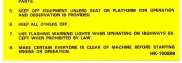
6 GENERAL PRECAUTIONS MAKE SURE everyone is clear of the equipment before starting the tractor's engine and while equipment is under operation. DO NOT allow anyone to ride on this equipment. KEEP hands, feet, hair and clothing away from all moving parts. Do not wear loose clothing while operating equipment, as this may present an entanglement hazard. DRIVE the pulling tractor at speeds compatible with conditions and good safety practices. This is especially important when operating over rough ground, on slopes, crossing ditches or while turning. Tip over may occur if a safe speed is not maintained during operation. STOP the tractor's engine and relieve any hydraulic pressure by actuating all hydraulic valves in both directions before disconnecting any part of the hydraulic system. MAKE SURE hitch components are attached securely before operating or transporting. USE flashing warning lights when on highways, except where prohibited by law. 6
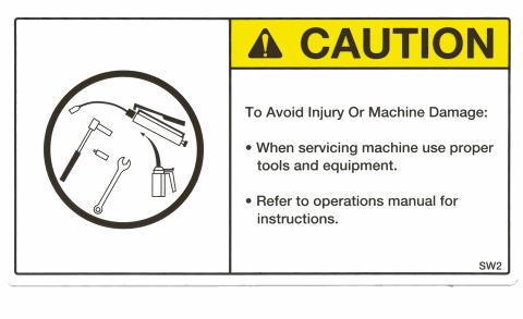
7 STOP tractor engine before leaving operator's position to adjust, lubricate, clean or unclog machine. KEEP all shields in place. DANGER! Chock wheels and block up head of machine securely prior to working under machine. Failure to do so may result in serious injury or death. MAXIMUM towing speed is 25 MPH. OBSERVE all safety decals located on machine. Should any safety decal become damaged unreadable, or lost, REPLACE IT IMMEDIATELY. New decals may be obtained from your Lewis Brothers' dealer. WEAR dust respirator at all times while using this machine (3M part # 8710 is recommended). R.O.P.S. use ROPS and seat belts whenever and wherever applicable. If your tractor has a foldable ROPS, fold it down only when absolutely necessary and fold it up and lock it again as soon as possible. Do not wear seat belt when the ROPS is folded. We strongly recommend the use of ROPS and seat belts in almost all applications. 7
8 WARRANTY 8
9 LEWIS BROTHERS MANUFACTURING, INC. LIMITED WARRANTY Lewis Brothers Manufacturing, Inc. (hereinafter referred to as LBM ) warrants each item of new equipment manufactured by LBM to be free from defects in material and workmanship under normal use and service. The obligation of LBM under this LIMITED WARRANTY is limited to repair or replacement, as LBM may elect, of any parts that prove, in LBM s judgment, to be defective in material and workmanship within the first twelve (12) months after the date of invoice to the original purchaser. THIS LIMITED WARRANTY DOES NOT APPLY TO BELTS, HYDRAULIC HOSES, TIRES, AND OTHER SERVICE ITEMS, WHICH SHALL HAVE A NINETY (90) DAY WARRANTY. THIS LIMITED WARRANTY WILL APPLY FOR (3) MONTHS ONLY WHEN THE UNIT IS USED IN A COMMERCIAL APPLICATION. All warranty part repairs and replacements must be made by a certified LBM dealer. Any outside work or alterations made without written approval of LBM will render this LIMITED WARRANTY void. LBM s obligation specifically excludes any liability for consequential damages, such as loss of profit, delays, expenses, damage to goods or property used in connection with or processed in or by the product sold, or damage to the product sold from whatever cause, whether or not such loss is due to negligence by LBM. This LIMITED WARRANTY shall not apply to any item that has been operated in a manner not recommended by LBM. No person is authorized to give any other warranties or to assume any other liability on behalf of LBM unless made in writing by Lewis Brothers Manufacturing, Inc. THIS LIMITED WARRANTY IS IN LIEU OF AND REPLACES ALL OTHER WARRANTIES, EXPRESSED OR IMPLIED. WARRANTIES OF MERCHANTABILITY AND FITNESS FOR A PARTICULAR PURPOSE ARE EXCLUDED, AS ARE ALL OTHER REPRESENTATIONS TO THE USER-PURCHASER AND ALL OTHER OBLIGATIONS OR LIABILITIES, INCLUDING LIABILITY FOR INCIDENTAL AND CONSEQUENTIAL DAMAGES, ON THE PART OF LBM. LEWIS BROTHERS MANUFACTURING, INC. P.O. BOX BAXLEY, GA FEBRUARY 1,
10 SPECIFICATIONS 10
11 SPECIFICATIONS Housekeeper Model # 5 Overall Working Height Overall Length Width (outside tires) Overall Width Throat Capacity Weight (unloaded) PTO Hydraulic Pump Hydraulic 540 rpm Tire Pressure 74 inches 22 1/2 feet 79 inches 83 inches 69 inches 175 cubic ft 6000 lbs. 22 gallons 2350 PSI 50 PSI Tire Size 12.5L L 16 Hydraulic Oil Oil Reservoir Capacity Tractor Horsepower required Tongue Weight (unloaded) AW GPM 60 HP 1350 lbs. 11
12 SETUP AND OPERATION 12

13 TRACTOR SETTINGS MACHINE SETUP The Lewis Poultry Housekeeper #5 should be attached at the fixed drawbar for proper operation. If your tractor has an option of a 540 or 1000 rpm PTO, you should install the 540 shaft. RECOMMENDED ATTACHMENT POINT HK HK HK HK HK HK HK Figure 1 ATTACHING HOUSEKEEPER TO THE TRACTOR Attach the Poultry Housekeeper to the tractor's fixed drawbar using a heavy-duty hitchpin. Next, attach the hydraulic pump to the tractor PTO shaft. Slide the pump onto the PTO shaft as far as possible. Secure its position by wrapping the chain on the torque arm around some portion of the tractor hitch which is secure and will not allow the pump to slide off or spin once the PTO is engaged. A good place to chain the pump is around the top link pin. Always try to pull the pump from the 13

14 PTO after it is chained into place. If the pump slides very far back on the shaft it is not snug enough. Take up another link on the chain and repeat the process again. Making this connection too tight may put excess pressure on the PTO shaft resulting in damage to pump or shaft. (See figure 1) The tongue of the unit can be moved to the far right position so that the pickup head will be positioned closer to the poultry house wall. Before starting to clean out a house, the operator should decide whether to start next to the walls or in the middle of the house and set the tongue accordingly. Always set the tongue back to the center position when not cleaning next to the walls or a row of posts, and before leaving the house. (See Figure 2) The main control valve should be adjusted so that it is easily accessible to the operator, but not so close that it will make contact with the tractor. CAUTION! The Oil Supply Valve Handle must be in the horizontal position at all times during operation in order to supply full flow to the system. Be sure to check before engaging the pump. Failure to maintain this position will damage the pump. HK HK OIL SUPPLY VALVE HANDLE Figure 2 14
15 OPERATING INSTRUCTIONS The Lewis Poultry Housekeeper is designed to be operated with the tractor PTO turning within a range of 500 to 540 RPM. 540 RPM is the most desirable speed and will produce the maximum flow and pressure from the pump. To put the machine into operation, first engage the PTO of the tractor and then pull the control valve handle forward. This should start the cylinder reel, loading conveyor and leveling assembly into motion. Next, bring the PTO of the tractor up to speed. The ground speed will depend on the particular operation being performed and the amount of material being removed from the floor of the house. Generally, first gear or 1 to 1-1/2 MPH is used for total clean out and removal of medium cake during sifting. Very heavy cake or excessive ground speed may cause litter to be pushed in front of the machine. The Poultry Housekeeper operates best at a depth of 3-4 inches. If litter or cake is deeper than four inches it is recommended that two passes be made through the house to clean or sift the litter. In excessive cake the ground speed may be reduced to help sift the total cake in a single pass. Higher gears may be used when sifting where the litter does not exceeded 3-4 inches and where cake is light. Speeds of the drive components are very important to the performance of the Poultry Housekeeper. PTO speeds in the ranges should be maintained at all times during operation. The ability to shake the loading conveyor while sifting the litter is what makes the Lewis Poultry Housekeeper work so well. Shaking makes the separation process work by allowing the smaller particles to pass through the screens while the larger cakes are tumbled for a short time before being carried into the body. The gentle lifting and shaking process keeps wet litter and feathers from passing through the screens. Setting and maintaining the proper blade depth is important for maximum performance. To properly set the depth, slowly lower the front of the Poultry 15
16 Housekeeper into the litter with your tractor. Lift until the desired depth is reached. It may take some time to become accustomed to how deep the blade is running. By observing the blade and loading cylinder during operation, proper depth can be determined for the given conditions. In houses where uniform amounts of material will be removed, set the stops on the tractor lift. This will provide consistent blade depth each time the machined is raised or lowered. The body loads from front to rear, and although it is sometimes difficult to see the rear of the machine because of the dust, the operator will know the body is full when the leveling bars begin to kick litter into the air. When this occurs, move the control valve handle to the center position to disengage the conveyor. The load is now ready to be transported and unloaded at the desired site. The body may be unloaded by spreading or by a quick dump method. If the spreading method is to be used, refer to the section on "Spreader Installation and Operation" on the following pages. To do a quick dump as in composting or stockpiling: 1. Make sure the bumper and spreader are not attached and that the hydraulic hoses are connected properly. Remove tailgate lock-down bolts and the tension springs from upper section of the tailgate. Store these in a secure place for later installation. 2. The center springs and pins should be installed between the upper and lower sections of the tailgate as shown in (figure 3). This will cause the tailgate to become rigid and function as one piece while litter is being transferred rearward. Failure to install these properly will result in improper unloading of litter. 3. Once you have reached the composting or unloading site, push the control valve lever to the rear and begin the unloading process. The unloading chain will drag the litter out the back of the machine. Forward movement of the machine may be necessary to allow for litter being discharged. 4. After all the litter has been discharged, pull away from the pile and move the control lever forward to the loading position This will engage the tailgate cylinder and cause the tailgate to return to the closed position. It is important to unload all the litter or the tailgate will not close properly. The machine is now ready to be re-loaded. CAUTION: Never back the Lewis Poultry Housekeeper while the loading assembly is in the down position and in operation! Litter and other objects may be 16

17 forced into the rear of the loading assembly and possibly cause the assembly to jam. Always lift the front of the machine or stop the assembly before backing the machine. Pin & Spring Assembly Figure 3 SPREADER INSTALLATION AND OPERATION 17
18 INSTALLATION 1. The spreader unit comes pre-assembled and is attached to the main frame of the Housekeeper using four 1/2x1-1/2 inch bolts.(see figure 4) 2. Locate the hydraulic 'quick-coupler' attached to the base end of the tailgate cylinder and uncouple the fittings from the coupling block (see fig. 5). Connect the two ends to the matching fittings on the hydraulic motor located on the spreader assembly. 3. Install the bumper and the diverter assembly. 4. Remove the pins and springs in the center section of the tailgate and store in a secure location. 5. Attach the lower tailgate tension springs from the tailgate to the frame OPERATION Two primary concerns when spreading litter are the amount being applied and the pattern of distribution. The settings for the discharge rate will vary depending on the consistency of the litter. The common setting for dry litter is position No. 5 on the control valve. The flow control valve may be increased or decreased depending on the volume of litter to be applied. The distribution pattern is influenced by the location of the diverter attached to the rear bumper. Best results are achieved when the diverter is positioned at approximately 45 degrees. (See Figure 6) Fresh litter may be spread in the house with the Housekeeper once the clean out process has been completed. Shavings may be loaded into the body of the Housekeeper with a front loading device or by picking up the shavings with the loading conveyor of the Housekeeper itself. If equipped with perforated bars, you will need to remove the shaker wheels and operate the Housekeeper in the slowest gear and speed. The unloading and spreading process requires a lot of hydraulic capacity both in volume and pressure. It is not uncommon for low horsepower tractors to become 18

19 heavily loaded during these operations. Slower speeds may be required if this situation occurs. WARNING! Do not operate the spreader with anyone standing behind the machine. The material being discharged is traveling at a high rate of speed and could contain objects capable of causing serious personal injury. Pin & Spring Attachment Bolts Figure 4 19

20 Coupling Block Figure 5 TURKEY OPERATIONS When the Lewis Poultry Housekeeper is used in very heavy turkey cake, it may become necessary to slow the ground speed to 1/2 MPH. This works best because it is very difficult to cut through turkey litter due to the very large feathers present. Additionally, feathers may wrap around the blade and loading cylinder, causing litter to be pushed ahead of the machine. The following procedure must be followed to properly remove the feathers from the loading blade. 1. Stop the tractor. 2. Disengage control valve. 3. Back the tractor up with the head in the down position. 4. Stop the tractor. 5. Engage control valve to loading position. 6. Start tractor in a forward motion again. 7. All feathers are wiped from the loading blade and are then loaded into the body. The wide head enables the Housekeeper to start from the walls and work towards the center of the house. There is little need to overlap since the head is as wide as the tire track. The floor is left smooth and ridge free. 20

21 Diverter Figure 6 TOWING AND TRANSPORTING A tractor of sufficient weight and power is required to both pull and control a Lewis Brothers Housekeeper over the terrain in the given area of operation. A tractor with a minimum of 60 PTO hp is required for proper operation of the # 5 Housekeeper. In order to have full control, your tractor must be able to maintain traction under all turf or surface conditions. Additional weights may be required to the front of the tractor to avoid unstable towing conditions. If it becomes necessary to tow the Poultry Housekeeper behind a truck for extended distances the following is recommended. Store the hydraulic pump on the support pin located on the tongue and secure it with the torque bar chain. Tie up all hoses to prevent them from dragging or becoming damaged. Tongue weight for towing is approximately 1300 to 1500 lbs. The truck used for towing must be heavy enough to pull the Housekeeper, but more importantly must be equipped to safely stop under the additional load. The hitch height must provide a clearance of five to six inches below the blade of the Housekeeper after the Housekeeper has been attached to the towing vehicle. Maximum caution should be maintained at all times when transporting the Lewis Housekeeper. 21

22 TOTAL CLEANOUT The # 5 Housekeeper is designed to give the operator total control over the amount of material removed during operation. This is done by adjusting the loading conveyor doors located on the underside of the conveyor assembly.(see Figure 6a ) The operator can remove as much or as little litter as desired by simply rotating the conveyor doors to the desired position. Conveyor Door Figure 6a The process of changing from a total caking or crusting operation must begin with the removal of the shaker rollers. These shaker rollers cause the loading chain to shake or shift the material and thus ensure that the separation process is completed. Start by removing one of the loading bars at the very top of the loading assembly. Next, slowly rotate the chain until the gap in the chain stops directly over the shaker rollers. (See Figure 6b) The shaker rollers may now be removed with a wrench. Once the shaker assemblies have been removed and the bars replaced, all of the conveyor doors may be closed for the total clean out operation. Reverse this procedure when replacing the shaker rollers. 22
 Press down on the wrench to relieve pressure on the door holder while at the same time removing the hairpin.")

23 REMOVE BAR TO ACCESS SHAKER ROLLER Figure 6b The four conveyor doors are used to regulate the amount of litter that is returned to the house floor. Open the doors by placing a 1-1/8 wrench down on the hex head door holder. (Figure 6c ) Press down on the wrench to relieve pressure on the door holder while at the same time removing the hairpin. This will allow the door to drop down into the open position. Repeat this procedure for the other side of the door. Open as many doors as needed to return the desired amount of material to the house floor. Figure 6c To return the door to the closed position, reach under the door and pick it up until the door closes. While holding the door closed with the pressure from the wrench, re-install the hairpin. The door will now remain closed. 23
24 STORAGE 24
25 STORAGE After each use, the Poultry Housekeeper should be washed down thoroughly removing all litter, inside and out. After washing, treating with a disinfectant is recommended in order to kill any remaining bacteria. The next step is treating the machine with soluble oil to protect it from rust and corrosion. One product that meets these requirements is called LPS#3. You may find this or other similar products at your Lewis Poultry Housekeeper Dealer; tractor dealerships or farm supply stores. It is important to remember that all chains must be properly lubricated after each use and especially before storage. CAUTION: When washing the Housekeeper, never allow a high-pressure water stream to come in contact with bearings or idler seals. Water can be forced into the bearing and will cause premature failure. Check all safety decals and make any necessary replacements. Decals may be obtained from your Lewis Dealer. 25
26 MAINTENANCE 26

27 MAINTENANCE CHAIN ADJUSTMENTS Periodical adjustments may be necessary to the conveyor chains, drive chains and leveling assembly chains. With the operator in front of the Housekeeper and facing towards the machine, the loading cylinder drive chain will be located on the right side of the machine. As it wears and stretches from use, the idler sprocket should be adjusted to remove any slack. Proper tension on the chain should allow for approximately 1 inch of movement in the tightness of chain. (See figure 7) IDLER SPROCKET For Proper Tension Allow 1" Movement Here Figure 7 27

28 The loading conveyor chain will also need adjusting as it wears. To adjust the tension on the chain, loosen all bolts on the base of the upper loading shaft bearing. Next, tighten the adjustment nut on the adjustment rod located at the top of the assembly. Be sure to adjust both sides of the assembly equally before securing the bolts. (See figure 8) LOOSEN BOLTS ADJUSTMENT NUT SHAKER WHEEL Figure 8 Proper tensioning of this chain should allow you to lift the chain off the side runners between 1-1\2 to 2 inches. (See Figure 8a) When the chain stretches far enough that it cannot be tightened, you must remove two links and one bar and reconnect the chain. Do this by grinding out selected link pins. Reassemble the chain by using an attaching link. Be sure to remove and replace any damaged bars or worn chain links. When adjusting the tension on the leveling chain, there should be contact between the chain and the lower runner with the chain slightly rising off the lower runner at the rear of the machine. (See Figure 8b) 28


29 Allow 1-1/2 to 2 inches adjustment as shown Figure 8a Excess sag should be adjusted out before operation Chain should slightly rise at rear of runner when properly tensioned Figure 8b 29

30 The leveling chain assembly is adjusted from the rear of the assembly. Begin by loosening the jam nut located on the adjustment rod. Next, loosen the bearing flange bolts and turn the adjustment rod to achieve the proper tension. Special care should be taken to adjust both sides of the assembly in equal amounts. Adjusting one side more than the other will cause misalignment of the assembly and damage the assembly. (See Figure 9) LOOSEN BOLTS ADJUSTMENT NUT Figure 9 The unloading chain adjustment is located at the front of the chain directly behind the lower portion of the loading conveyor. Adjust both sides of the idler shaft assembly equally by tightening the adjustment nut. (See fig. 10) The chain should be tightened until approximately 5-3/4" clearance exists between it and the body floor in order to achieve proper tensioning. This should place the bottom of the chain even with, or just below the main frame channel. 30
 Proper adjustment should allow for 1/2\" to 1\" of movement on the tension side of the chain when not under a load.")
31 Adjustment Nut Jam Nut Figure 10 The unloading drive chain can be adjusted by loosening the idler and sliding it downward in the slot. (See Figure 11) Proper adjustment should allow for 1/2" to 1" of movement on the tension side of the chain when not under a load. Once the correct tension has been set, secure the idler by tightening the idler bolt and reinstall the guard. 31

32 Idler Bolt Idler Figure 11 The drive belts on the spreader assembly may need to be adjusted over time. The first step after removing the protective guard is to loosen the idler axle bolt. Tighten the adjustment nut on the draw bolt until the proper tension is achieved. Re-secure the idler assembly by tightening the idler axle bolt. (See Figure 12) It should take 4-5 pounds of force to deflect a single belt 5/16 of an inch at the midpoint of the longest span. If no gauge is available to make this measurement, an alternative method of measurement would be to apply moderate force using one finger to push the belt 5/16 of an inch. Once the proper tension has been achieved for each of the belts, secure their position by tightening the jam nut and axle bolt. 32

33 Idler Axle Bolt Adjustment Nut Figure 12 The loading conveyor drive chain should be checked often and any loose slack should be adjusted out before operation. This can be done by first removing the protective guard and loosening the three bolts that secure the hydraulic motor and shaft assembly. (See figure 13) Once the bolts have been loosened, slide the Motor Mount Assembly down-ward to set the proper tension on the Drive Chain, and then lower Chain Idler against the Drive chain. Be careful not to over-tighten the chain as excess tension may cause damage to the loading motor assembly. After prolonged use, it may be necessary to remove a half link in order to take up slack due to stretching or wear. Follow the same steps as mentioned above once the half link has been removed. 33


34 Mounting Bolts Chain Idler Proper chain adjustment should allow ¼ movement Adjustment Rod Figure 13 The leveling assembly drive chain should also be checked regularly and adjusted as needed. After removing the guard, locate and loosen the leveling shaft assembly bolts. (See figure 14) Use the adjustment rod to set the proper tension on the drive chain taking care not to over-tighten. Once the proper adjustment has been made re-tighten the assembly bolts and re-install the guard. ATTENTION: Be sure to keep all drive chains well lubricated and free of obstructions to insure proper operation. 34

35 Assembly Bolts Adjustment Rod Proper chain adjustment should allow 1/4" movement Figure 14 LUBRICATION HYDRAULIC FLUID The hydraulic fluid is a vital component of the system. Low levels may cause overheating and damage to hydraulic components. The hydraulic system holds approximately 28 gallons. With the machine on level ground, the oil level in the tank should come to within four inches of the top of the tank. If it becomes necessary to add hydraulic fluid, use petroleum based anti-wear hydraulic oil with ISO 68 viscosity grade AW 68. Oil temperature should not exceed 180 degrees Fahrenheit. In the event that components may need replacing, the hydraulic oil should also be replaced. 35
36 CAUTION: Always look for hydraulic leaks with the tractor s engine off. Wear hand and eye protection. Use cardboard or wood instead of your hands to search for a leak source. Grease the following points lightly each 50 hours and before storage. 1. Spreader Shaft Bearing 2. Rear Unloading Shaft Bearing 3. Tandem Axle Pivots (Under the Axle) 4. Loading Shaft (Top) Bearing 5. Rear Leveling Shaft Bearing 6. Cylinder Reel Bearings 7. Main Loading Motor Support Bearings 8. Pivot Point on Tailgate Spring Unit (Hydraulic dump only) 9. Grease or oil tailgate hinges after each use. 10. Front Unloading Shaft (1 sprocket only) Grease all chains and bearings after each use. Change the oil filter every six (6) to twelve (12) months depending on usage. TIRES Check tire pressure on a regular basis. Adjust the pressure not to exceed 50 PSI. REPAIRS Check for worn or damaged components. Order needed parts from your Lewis Dealer. Make all repairs as early as possible to avoid additional expense. Prolonged use of worn or damaged parts may result in premature failure of other components. 36
37 DECALS 37


38 MODEL # 5 HK HK HK HK HK HK HK HK


39 HK HK HK HK HK HK HK
40 PARTS 40

41 HW Z HK HW G5Z HK HW Z HK HK HW ZG5 Leveling Shaft Assembly (HK ) Shaft HK Sprocket HK Bearing HK Key 5/16 Square x 2-1/ Adjustment Rod Assembly HK Tensioning Rod Assembly HW G5Z Bolt HW Z Flat Washer HW Z Lock Washer HW ZG5 Nut 41
 HK-100429 Bearing HK-100496 Key, 5/16 Square X 2-1/2 05-100836 Slide, Leveling Conveyor HW-550101 HK-100486 HK-100495")

42 HK HK Upper Loading Conveyor Shaft Assembly ( ) Shaft, Top Loading HK Sprocket, Top Loading w/ Angular Ring (after serial # 5468) HK Bearing HK Key, 5/16 Square X 2-1/ Slide, Leveling Conveyor HW HK HK HK HK HK Lower Loading Conveyor Shaft Assembly ( ) HK Shaft, Lower Loading (after serial # 5468) HK Sprocket, Lower Loading with Bushing HK Sprocket with Keyway HK Bearing HK Key, Cylinder Reel, ¼ Square HW /8 NPT Straight Grease Fitting 42


43 HK HK HK HK Rear Unloading Shaft Assembly (HK ) HK HK HK HK Shaft, Rear Unloading Sprocket Bearing Sprocket HK HK HK HK HK Front Unloading Shaft Assembly (HK ) HK HK HK HK HK Shaft, Front Unloading Sprocket With Grease Fitting Sprocket With Set Screw Bearing, Flange Tensioning Rod Assembly 43

")

44 HK HK HK WR HK Cylinder Reel Assembly HK Bearing HK Sprocket WR Bushing HK Key 3/8 Square X 2-1/2 HK Cylinder (HK ) HK HK HW NEZ HK HW NEZ Shaker Wheel Assembly (HK ) HK HW NEZ HW NEZ HK HK Shim-Space Locknut, Hex 5/8-11NC, ZP Nylon Locknut, Hex ¾-10NC, ZP Black Shaker Wheel, Nylon Shaft Assy, Shaker Wheel 44

45 HK HK HK HK HK HK HK HK HK Spinner Option HK HK HK HK HK HK HK HK HK Shaft with Blade Weldment, RH Shaft with Blade Weldment, LH Bearing Pulley Pulley, Spreader Idler Belt Adjustment Rod Pulley, Leveling Spinner Motor Belt 45
 HK-101658 Offset Link (not")
46 HK HK HK HK HK Unloading Motor & Parts HK Unloading Motor HK Idler HK Sprocket HK Drive Chain HK Sprocket, Unloading Drive HK Connecting Link (not shown) HK Offset Link (not shown) 46
 HK-101320")
47 HK HK HK WR HK HK HK Cylinder Motor & Parts HK HK HK Chain, #60 Roller, 95 Pitches HK Guard Mount HK Cylinder Motor HK Sprocket, 60 SDS 18H HK Taper Bushing HK Idler HK Spacer, Idler Leveling Chain HK Sprocket WR Bushing HK Connecting Link (not shown) HK Offset Link (not shown) 47

 HK-100670 Bar")
48 HK HK Unloading Chain (HK ) HK HK Chain Link Unloading Bar Assy HK HK Leveling Chain Assembly Part Number Description Quantity HK Chain 1 HK Bar 22 HW L9 Nut 44 HW L9YZ Bolt 44 HK Bar Attaching Link (not shown) HK Bar Attaching Link (not shown) 48
 HK-101001 1-1/2 Mesh Shaker Bar (No Peg) 24 HK-101268 1-1/2")
 HK-101624 HK-101646 PTO PUMP KIT (HK-101639) Part Number Description Quantity HK-101646 Torque Arm Weldment 1")
49 HK HK HK HK HK Loading Chain (HK ) & Bar Kit Complete Part Number Description Quantity HK Loading Chain with Bolt Shaker Bar Kit 1 (Option) HK /2 Mesh Shaker Bar (No Peg) 24 HK /2 Mesh Shaker Bar (5 Peg) 9 HK /2 Mesh Shaker Bar (6 Peg) 8 HK Mesh Angle Bar (5Peg) 8 HK Bar Attaching Link RH & LH (not shown) HK HK PTO PUMP KIT (HK ) Part Number Description Quantity HK Torque Arm Weldment 1 HK Pump 1 49

50 FITTINGS AND ADAPTERS # PART # DESCRIPTION # PART # DESCRIPTION 1 HK HYD. ELBOW 2 HK HYD. ELBOW 3 HK HYD. ELBOW 4 HK HYD. ADAPTER 5 HK HYD. ADAPTER 6 HK HYD. ADAPTER 7 HK HYD. ADAPTER 8 HK HYD. ELBOW 9 HK HYD. ELBOW 10 HK PORT ADAPTER 11 HK SWIVEL ADAPTER 12 HK HYD. ADAPTER 13 HK HYD. ELBOW 14 HK HYD. ELBOW 15 HK HYD. ELBOW 16 HK HYD. ADAPTER 17 HK SWIVEL ADAPTER 18 HK REDUCER 19 HK REDUCER 20 HK HYD. ELBOW 21 HK HYD. ELBOW 22 HK HYD. ADAPTER 23 HK QUICK COUPLER KIT 24 HK /4 NIPPLE 25 HK /2 NIPPLE 26 HK BUSHING 27 HK TEE 28 HK ¾ HYD. TEE 29 HK HYD. ELBOW 30 HK ¾ HYD. TEE 31 HK ½ HYD. TEE 32 HK ½ HYD. TEE 33 HK CAP, QUICK CONNECT 34 HK PLUG, QUICK CONNECT 50

51 HYDRAULIC HOSES HK HK HK HK HK HK HK HK HK HK HK HK HK HK HK HK HK HK HK EX-12FJ-276 LG 12EX-12FJ-12MJ-192 LG 12EX-12FJ90-12MJ-145 LG 12EX-12FJ LG 20PE-20MP-108 LG 12EX-12FJ-96 LG 12EX-12FJ-92 LG 12EX-12FJ-12MOBX-72 LG EX08-08MPX-08MP-96 LG 6AXT-6FJ-218 LG EX06-06FJ-132 LG 8AXT-8MPX-8FJ-94 LG 8AXT-8MP-8FJ-47 LG 8AXT-8FJ-8MP-45 LG 8AXT-12FJ-8MPX-42 LG 8AXT-8FJ-8FJ-23 LG 8AXT-8FJ-8MPX-23 LG 8AXT-8FJ-20 LG 4AXT-6FJ-4MPX-50 LG HK HK HK HK HK HK HK HK HK HK


52 HK HK Leveling Motor Assembly HK HK Loading Motor Assembly 52

53 HK HK HK HK HK HK


54 HK HK HK HK HK Variable Speed Valve 2 H1071 Handle 3 HK Control Valve Valve Handle 5 HK Elbow 12MB - 12FJX 6 HK Elbow 12 MB - 12 MJ 7 HK Tee 12 FP - 12 MJ - 12 MJ 8 HK Bushing 12 MP - 4 FP 9 HK Gauge 10 HK Elbow 12MB - 12 MJ 54

55 HK HK HK HK Part Number Description Quantity HK Filter Assembly 1 HK Filter Replacement 1 HK Nipple 1-1/4 X 1-1/4 1 HK Ball Valve 1 HK Strainer 1 55
56 Full Load Indicator Kit HK HK WR Part Number HK HK HK HK Hk HK WR HW SS HW ZG5 HK Description Full Load Indicator Kit Insulated Ring Terminals Electrical Cable 16/2 sjow Type Momentary Push Button Switch Light Non Strip Splicer Fuse Holder Bolt, HH, ½-13NC x 1-1/2 LG 18-8 Stainless Steel Nut, Hex, ½-13NC Zinc Plated, Gr5 Switch Activator Weldment 56
57 HK HK


58 Spinner Bumper Assembly Ref. Part # Description 1 HK Bumper, Front 2 HK Flow Divider Weldment 3 SP U-Bolt 4 HW G5Z Bolt, HH, Sp, 1/2"-13nc x 1-1/2, Gr5 5 HW Z Washer, Flat, 1/2" ZP USS Std 6 HW Z Washer, Lock, 1/2" ZP 7 HW ZG5 Nut, Hex, 1/2"-13nc, ZP 8 HK Bumper, Rear 58


59 Optional Electric Control Valve Kit HK
LEWIS WINDROWER OWNER / OPERATOR MANUAL
 LEWIS WINDROWER OWNER / OPERATOR MANUAL MODEL # WR-1 WINDROWER Manufactured by: LEWIS BROTHERS MANUFACTURING, INC. Post Office Box 146 Baxley, GA 31513 Tel: (912) 367-4651 Fax: (912) 367-3958 2-21-14 1
LEWIS POULTRY HOUSEKEEPER OWNER / OPERATOR MANUAL
 LEWIS POULTRY HOUSEKEEPER OWNER / OPERATOR MANUAL MODEL # DB-1 DUMP BODY FROM: SERIAL # 6679 Manufactured by: LEWIS BROTHERS MANUFACTURING, INC. Post Office Box 146 Baxley, GA 31513 Tel: (912) 367-4651
LEWIS POULTRY HOUSEKEEPER OWNER / OPERATOR MANUAL
 LEWIS POULTRY HOUSEKEEPER OWNER / OPERATOR MANUAL MODEL # 4 HOUSEKEEPER FROM: SERIAL # 8016 Manufactured by: LEWIS BROTHERS MANUFACTURING, INC. Post Office Box 146 Baxley, GA 31513 Tel: (912) 367-4651
CRUSTBUSTER OWNER / OPERATOR MANUAL
 CRUSTBUSTER OWNER / OPERATOR MANUAL MODEL # CB-1 CRUSTBUSTER Manufactured by: LEWIS BROTHERS MANUFACTURING, INC. Post Office Box 146 Baxley, GA 31513 Tel: (912) 367-4651 Fax: (912) 367-3958 5-2-17 1 INTRODUCTION
LEWIS POULTRY HOUSEKEEPER OWNER / OPERATOR MANUAL
 LEWIS POULTRY HOUSEKEEPER OWNER / OPERATOR MANUAL MODEL # DB-2 DUMP BODY HOUSEKEEPER FROM: SERIAL # 5177 Manufactured by: LEWIS BROTHERS MANUFACTURING, INC. Post Office Box 146 Baxley, GA 31513 Tel: (912)
LEWIS POULTRY HOUSE BLOWER OWNER / OPERATOR MANUAL
 LEWIS POULTRY HOUSE BLOWER OWNER / OPERATOR MANUAL MODEL # PB-1 Manufactured by: Lewis Brothers Manufacturing, Inc. Post Office Box 146 Baxley, GA 31515 Telephone: (912) 367-4651 Fax: (912) 367-3958 1
OPERATOR'S MANUAL 304 Row Mulcher
 OPERATOR'S MANUAL 0 Row Mulcher PUBLICATION DATE: // Millcreek Manufacturing Company Reservoir Road Honey Brook PA MILLCREEK PART# 0 WARNING: DO NOT assemble, operate, or maintain this equipment without
LEWIS POULTRY HOUSECLEANER OWNER / OPERATOR MANUAL
 LEWIS POULTRY HOUSECLEANER OWNER / OPERATOR MANUAL MODEL # SP-2 ECONOMY HOUSECLEANER Manufactured by: Lewis Brothers Manufacturing, Inc. Post Office Box 146 Baxley, GA 31515 Telephone: (912) 367-4651 Fax:
Model 858-RH. Operating and Assembly Manual. Palmor Products Inc Serum Plant Road Thorntown, IN 46071
 Model 5-RH Operating and Assembly Manual Palmor Products Inc. 55 Serum Plant Road Thorntown, IN 6071 3/31/015 SAFETY RULES Remember, any power equipment can cause injury if operated improperly or if the
Operating and Assembly Manual
 Model 1080 Operating and Assembly Manual Midwest Equipment Manufacturing, Inc. 5225 Serum Plant Road Thorntown, IN 46071 08-02-16 SAFETY RULES Remember, any power equipment can cause injury if operated
610 BUSHEL MANURE SPREADER
 610 BUSHEL MANURE SPREADER RODA MANUFACTURING 1008 LOCUST ST. HULL, IA. 51239 Art s-way Manufacturing 712-439-2366 Co., Inc. Hwy 9 West - PO Box 288 WWW.RODAMFG.COM Armstrong, IA. 50514 U.S.A 2 INTRODUCTION
Airflo MANUFACTURING CO., INC.
 Airflo MANUFACTURING CO., INC. 365 UPPER OAKWOOD AVE, ELMIRA NY 14903 PHONE: 607-733-8284 / FAX: 607-733-0587 OPERATOR & PARTS MANUAL PSV-8L ELECTRIC SPREADER Visit our website at www.air-flo.com Contents
STOP. 44" High Speed Sweeper. Operator's Manual. Model No Safety Assembly Operation Maintenance Parts
 Operator's Manual STOP 44" High Speed Sweeper Model No. 486.029 DO NOT RETURN TO STORE For Missing Parts or Assembly Questions Call 1-866-576-8388 CAUTION: Before using this product, read this manual and
03-SERIES 4 & 6-ROW RIGID & FOLDING PEANUT VINE CONDITIONER OPERATOR S MANUAL THIS MANUAL TO ACCOMPANY MACHINE
 03-SERIES 4 & 6-ROW RIGID & FOLDING PEANUT VINE CONDITIONER OPERATOR S MANUAL THIS MANUAL TO ACCOMPANY MACHINE PART NO. 03-OM-03 Printing Date: SEPT 2012 WARRANTY POLICY KELLEY MANUFACTURING COMPANY (KMC)
Wheel Horse. 44 Snowthrower. for 5xi Lawn and Garden Tractors. Model No & Up. Operator s Manual
 FORM NO. 8 Rev A Wheel Horse Snowthrower for 5xi Lawn and Garden Tractors Model No. 7966 890050 & Up Operator s Manual IMPORTANT: Read this manual, and your tractor manual, carefully. They contain information
OPERATOR S MANUAL with Parts List & Warranty. For Model 100SP Topdresser
 OPERATOR S MANUAL with Parts List & Warranty For Model 100SP Topdresser July 30, 2009 Model 100SP Topdresser LIMITED WARRANTY Earth & Turf Products, LLC warrants to the original Purchaser, all Earth &
FORAGE BOX MODEL 5300 REAR UNLOAD OPERATOR'S MANUAL DO NOT OPERATE THIS EQUIPMENT UNTIL THIS MANUAL HAS BEEN READ AND UNDERSTOOD.
 FORAGE BOX MODEL 5300 REAR UNLOAD OPERATOR'S MANUAL DO NOT OPERATE THIS EQUIPMENT UNTIL THIS MANUAL HAS BEEN READ AND UNDERSTOOD. Miller-St. Nazianz, Inc. Art s-way Manufacturing Co., Inc. P.O. Box 127
25 BUSHEL MANURE SPREADER
 25 BUSHEL MANURE SPREADER RODA MANUFACTURING 338 MAIN ST. HULL, IA. 51239 Art s-way Manufacturing 712-439-2366 Co., Inc. Hwy 9 West - PO Box 288 WWW.RODAMFG.COM Armstrong, IA. 50514 U.S.A 2 INTRODUCTION
LEWIS POULTRY HOUSECLEANER OWNER / OPERATOR MANUAL
 LEWIS POULTRY HOUSECLEANER OWNER / OPERATOR MANUAL MODEL # SP-1 DELUXE HOUSECLEANER Manufactured by: Lewis Brothers Manufacturing, Inc. Post Office Box 146 Baxley, GA 31515 Telephone: (912) 367-4651 Fax:
TABLE OF CONTENTS. Warranty Disclaimers Delivery Checklist After Sale Checklist Safety Set Up... 8
 TABLE OF CONTENTS Pickett Equipment Warranty... 2 Warranty Disclaimers... 3 Delivery Checklist... 4 After Sale Checklist... 4 Safety... 5-7 Set Up... 8 Machine Adjustments and Operation... 9 Maintenance
ROTARY TILLER. Operation, Service & Parts Manual For "AS" Series. FORM: ASTillerBook.QXD
 ROTARY TILLER Operation, Service & Parts Manual For "AS" Series FORM: ASTillerBook.QXD April 2002 TABLE OF CONTENTS Preparation......................................1 Assembly Instructions.............................2
BX7322 Adventurer Tow Bar Operator Manual & Installation Instructions
 Please visit www.blueox.com for the latest version of these installation instructions. BX7322 Operator Manual & Installation Instructions Serial Number (5,000 lb) 2 Inch Coupler 292-1263 Rev J Page 1 of
Quiet Collector. Model No & Up
 FORM NO. -8GB Rev A Quiet Collector Model No. 795-890000 & Up Operator s Manual IMPORTANT: Read this manual, and your tractor manual, carefully. They contain information about your safety and the safety
SPINNER SPREADER. Operation, Service & Parts Manual For Models S203L, S273L & S503L. May Form: Spnsprdr.PM65
 SPINNER SPREADER Operation, Service & Parts Manual For Models S20L, S27L & S0L May 200 Form: Spnsprdr.PM TABLE OF CONTENTS Welcome/Introduction... 1 Training... 1 PreOperation... 1 Spreader Assembly...2
CAUTION CAUTION indicates a potentially hazardous situation which, if not avoided, may result in minor or moderate injury.
 Instruction Manual Notes: Page Manual Conventions This manual uses the following symbols to help differentiate between different kinds of information. The safety symbol is used with a key word to alert
FLAIL MOWER SHREDDER
 FLAIL MOWER SHREDDER Operation, Service, & Parts Manual For Models: GML41, 49, 61, 69, & 79 February 2006 FORM: GMLMower.QXD TABLE OF CONTENTS Installation....................................................1
Table of Contents WARN INDUSTRIES PAGE A1
 INSTALLATION INSTRUCTIONS AND OPERATORS GUIDE ProVantage Bucket Conversion Kit Part Number: 84133 (50 ), 83133 (54 ) and 85133 (60 ) Application: Front Mount Plow* * Not recommended for use with Center
Wood Chipper Model C550M Operator's Manual
 Wood Chipper Model C550M Operator's Manual THIS MANUAL MUST BE READ AND UNDERSTOOD BEFORE ANYONE OPERATES THIS MACHINE! Manual# 990023 Revised 01/2010 YOU MUST FILL OUT YOUR WARRANTY REGISTRATION TO ACTIVATE
BX7322 Adventurer Tow Bar Operator Manual & Installation Instructions
 Please visit www.blueox.com for the latest version of these installation instructions. BX7322 Operator Manual & Installation Instructions Serial Number (5,000 lb) 2 Inch Coupler 292-1263 Rev J Page 1 of
SAFETY. Hitchpole, centre frame 1. Centre frame wheels & roller 3. Centre & wing frames 5. Wing frame wheels & roller 9.
 MANUAL Hitchpole, centre frame 1 Centre frame wheels & roller 3 Centre & wing frames Wing frame wheels & roller 9 Hydraulics 11 Clearance lights 13 Operations 1 Safety, warranty 1 SAFETY Industrial Drive,
LIMITED WARRANTY DISCLAIMER OF IMPLIED WARRANTIES & CONSEQUENTIAL DAMAGES
 Published 08/15 LIMITED WARRANTY Bush Hog warrants to the original purchaser of any new Bush Hog equipment, purchased from an authorized Bush Hog dealer, that the equipment be free from defects in material
STOP 42" HIGH SPEED LAWNSWEEPER. Owner's Manual. Model No's Safety Assembly Operation Maintenance Parts
 Owner's Manual STOP 42" HIGH SPEED LAWNSWEEPER Model No's. 486.242223 DO NOT RETURN TO STORE For Missing Parts or Assembly Questions Call 1-866-576-8388 CAUTION: Before using this product, read this manual
OWNER S MANUAL Z SERIES TRACKS. Rev. 355_05
 OWNER S MANUAL Z SERIES TRACKS Rev. 355_05 LOEGERING 800-373-5441 15514 37 th Street SE 701-347-5441 Casselton, ND 58012 USA Fax: 701-347-4323 E-Mail: lmi@loegering.com Internet: www.loegering.com Loegering
J. & M. Mfg. Co., Inc. 284 Railroad Street - P.O. Box 547 Fort Recovery, OH Ph: (419) Fax: (419)
 Fax: (419)") OPERATORS MANUAL Rev.8.14.17 Talc Applicator (Hydraulic) J. & M. Mfg. Co., Inc. 284 Railroad Street - P.O. Box 547 Fort Recovery, OH 45846 Ph: (419) 375-2376 Fax: (419) 375-2708 www.jm-inc.com 2 Table
OPERATORS MANUAL Rev.8.14.17 Talc Applicator (Hydraulic) J. & M. Mfg. Co., Inc. 284 Railroad Street - P.O. Box 547 Fort Recovery, OH 45846 Ph: (419) 375-2376 Fax: (419) 375-2708 www.jm-inc.com 2 Table
Drive Over- Pit. Belt Accelerator & Multi-Purpose Belt Loader OWNER'S MANUAL (08/08)
") Drive Over- Pit Belt Accelerator & Multi-Purpose Belt Loader OWNER'S MANUAL 00028100 (08/08) Belt Accelerator & Multi-Purpose Belt Loader Table of Contents Warranty Information................. Inside
Drive Over- Pit Belt Accelerator & Multi-Purpose Belt Loader OWNER'S MANUAL 00028100 (08/08) Belt Accelerator & Multi-Purpose Belt Loader Table of Contents Warranty Information................. Inside
RED23305 Owner s Manual
 RED23305 Owner s Manual 5 foot, 3-Point Mounted Snow Blower 270 West Park Avenue Huron, SD 57350 866-526-5682 Serial Number: Date of Purchase: Red Devil Snow Blower See Figure 1. 1. The Red Devil Snow
OPERATOR S MANUAL FABRIC 3-BAG GRASS CATCHER PART NO PRINTED 8/2012 PRINTED IN USA
 OPERATOR S MANUAL FABRIC -BAG GRASS CATCHER Models: GC-STC-V This manual contains the operating instructions and safety information for your Scag mower accessory. Reading this manual can provide you with
BX4330 Acclaim Tow Bar Operator Manual & Installation Instructions
 Operator Manual & Installation Instructions (5,000 lb) 2 Inch Coupler General Information DO NOT INSTALL, OPERATE OR USE THIS EQUIPMENT UNTIL THE FOLLOWING OPERATING AND SAFETY INSTRUCTIONS HAVE BEEN READ
OPERATING INSTRUCTIONS AND PARTS MANUAL
 Assembled in USA WARNING ATENCION ATTENTION OPERATING INSTRUCTIONS AND PARTS MANUAL 89143380-2 For technical assistance or the Dealer nearest you, call (360) 833-1600 8.914-338.0 2 CONTENTS Introduction...
THE GIANT-VAC PTO BLOWER MODELS 2000*/3200**/4000***
 THE GIANT-VAC PTO BLOWER MODELS 2000*/3200**/4000*** Congratulations! ASSEMBLY INSTRUCTIONS AND OPERATOR S MANUAL You have just purchased one of the finest pieces of outdoor power equipment on the market
Right Hand Groomer Kit Left Hand Groomer Kit Reelmaster 5500 D, 6500 D & 6700 D
 Right Hand Groomer Kit Left Hand Groomer Kit Reelmaster 00 D, 600 D & 6700 D Model No. 08 Model No. 080 Form No. 7 Rev B Installation Instructions Note: The Right and Left Groomer Kits can be used on Reelmaster
POST HOLE DIGGER. Operation, Service & Parts Manual For Models D20 & D40. FORM: D20_40DigRev.QXD
 POST HOLE DIGGER Operation, Service & Parts Manual For Models D20 & D40 FORM: D20_40DigRev.QXD September 2006 Revised August 2009 TABLE OF CONTENTS Introduction.............................1 Preparation..............................2
TABLE OF CONTENTS DESCRIPTION. Safety Instructions & Safety Sign Locations Operating Instructions Assembly Instructions...
 TABLE OF CONTENTS DESCRIPTION PAGE Warranty... 1 Safety Instructions & Safety Sign Locations... 2 Operating Instructions... 3 Assembly Instructions... 5 500 & 600 Snowblower Drawings... 8 500 & 600 Snowblower
OWNER S MANUAL. LOEGERING th Street SE Casselton, ND USA Fax:
 OWNER S MANUAL TRAIL BLAZERS and D SERIES TRACKS LOEGERING 800-373-5441 15514 37 th Street SE 701-347-5441 Casselton, ND 58012 USA Fax: 701-347-4323 E-Mail: lmi@loegering.com Internet: www.loegering.com
KING COBRA/CALIBER GRASS COLLECTION SYSTEM PARTS & OPERATORS MANUAL
 KING COBRA/CALIBER GRASS COLLECTION SYSTEM PARTS & OPERATORS MANUAL GRASS CATCHER W/WEIGHTS: TUBE KITS: BLOWER KITS: 52 542128 52 542119 5101002 60 542129 60 542120 5101003 2 WORLDLAWN POWER EQUIPMENT
SHEYENNE TELE-BOOM OWNERS MANUAL OPERATOR INSTRUCTIONS PARTS BOOK
 SHEYENNE TELE-BOOM OWNERS MANUAL OPERATOR INSTRUCTIONS PARTS BOOK 701 Lenham Ave. SW PO Box 647 Cooperstown ND 58425 1-800-797-1883 701-797-2700 * 701-797-2584 Fax www.sheyennemfg.com TABLE OF CONTENTS
WOOD CHIPPER WC1103 5PQ (8/02/12)
") O P E R A T O R ' S M A N U A L WOOD CHIPPER WC1103 5PQ990101 (8/02/12) To the Owner; Thank-You for choosing a quality product from Frontier Equipment. We strive to give you the best equipment and the
O P E R A T O R ' S M A N U A L WOOD CHIPPER WC1103 5PQ990101 (8/02/12) To the Owner; Thank-You for choosing a quality product from Frontier Equipment. We strive to give you the best equipment and the
Talet Equipment International Ltd. Sand Kicker
 Talet Equipment International Ltd. Sand Kicker Parts & Operators Manual P.O. Box 35 Strathmore AB Canada TP K3 www.taletattachments.com sales@taletattachments.com Toll Free -888-37-5878 Fax -403-934-304
BX4330 Acclaim Tow Bar Operator Manual & Installation Instructions
 Please visit www.blueox.com for the latest version of these installation instructions. BX4330 Operator Manual & Installation Instructions Serial Number (5,000 lb) 2 Inch Coupler 292-2205 Rev L Page 1 of
OPERATOR S MANUAL REPAIR PARTS CATALOG. Models: SCP-51 & SCP-71 SCP-52 & SCP-72 SCP-91 & SCP-111 SCP-92 & SCP-112 BRILLION FARM EQUIPMENT
 OPERATOR S MANUAL REPAIR PARTS CATALOG Subsoil Chisel Plow Models: SCP-51 & SCP-71 SCP-52 & SCP-72 SCP-91 & SCP-111 SCP-92 & SCP-112 IMPORTANT! Repairs cannot be purchased retail direct from factory. Order
Quiet Collector. Model No & Up
 FORM NO. -0 Quiet Collector Model No. 79-990000 & Up Operator s Manual IMPORTANT: Read this manual, and your tractor manual, carefully. They contain information about your safety and the safety of others.
Operating and Assembly Manual
 Model 470-/H/PRO/IC Operating and Assembly Manual Midwest Equipment Manufacturing, Inc. 5225 Serum Plant Road Thorntown, IN 46071 11-11-11 SAFETY RULES Remember, any power equipment can cause injury if
WARRANTY REGISTRATION AND POLICY
 WARRANTY REGISTRATION AND POLICY Buhler Manufacturing products are warranted for a period of twelve (12) months from original date of purchase, by original purchaser, to be free from defects in material
DFS Vac Collection System 400 Series Z Master
 Form No. 0 DFS Vac Collection System 00 Series Z Master Model No. 780 Serial No. 000000 and Up Operator s Manual Register your product at www.toro.com Original Instructions (EN/GB) Contents Page Introduction................................
OPERATOR'S MANUAL & PARTS CATALOG 12 TON RUNNING GEAR
 Unverferth Grain Handling Systems OPERATOR'S MANUAL & PARTS CATALOG 1 TON RUNNING GEAR Model RGE- Unverferth Manufacturing Co., Inc. Box 7 Kalida, OH 8 Part No. 00 PH: 1-- FAX: 1--8 www.unverferth.com
BX4330 Acclaim Tow Bar Operator Manual & Installation Instructions
 Operator Manual & Installation Instructions Serial Number (5,000 lb) 2 Inch Coupler 292-2205 Rev J Page 1 of 7 4/23/13 DO NOT INSTALL, OPERATE OR USE THIS EQUIPMENT UNTIL THE FOLLOWING OPERATING AND SAFETY
MK AUGERS POWER SWING KIT ASSEMBLY & OPERATION MANUAL
 MK AUGERS POWER SWING KIT ASSEMBLY & OPERATION MANUAL Read this manual before using product. Failure to follow instructions and safety precautions can result in serious injury, death, or property damage.
4745 Drill OWNER'S MANUAL (06-08) #
 #") 4745 Drill OWNER'S MANUAL (06-08) # 605865 Identification Your CrustBuster drill is identified by a Serial Number and Model Number. Record these numbers in the spaces provided in this manual and refer
4745 Drill OWNER'S MANUAL (06-08) # 605865 Identification Your CrustBuster drill is identified by a Serial Number and Model Number. Record these numbers in the spaces provided in this manual and refer
Richmond Conveyor. Hydraulic Ultimate Manual. January 2013
 Richmond Conveyor Hydraulic Ultimate Manual January 2013 Table of Contents Operators Manual Removing conveyor from truck Maintenance checklist Maintenance kit material list Safety information Index Installation
DIAMONDBACK/EDGE GRASS COLLECTION SYSTEM PARTS & OPERATORS MANUAL
 DIAMONDBACK/EDGE GRASS COLLECTION SYSTEM PARTS & OPERATORS MANUAL GRASS CATCHER W/WEIGHT: TUBE KIT: BLOWER KIT: 48 5101305 632093 632078 52 5101305 542119 632074 60 632086 542120 632081 3 WORLDLAWN POWER
ACCLAIM OPERATOR, PARTS, AND INSTALLATION MANUAL BX4330 ACCLAIM
 ACCLAIM OPERATOR, PARTS, AND INSTALLATION MANUAL BX4330 ACCLAIM Tow Bar Class III (5000 lb) 2 Inch Coupler TOWING PRODUCTS DIVISION Page 1 of 8 292-2205 4/23/09 SAFETY DO NOT INSTALL, OPERATE OR USE THIS
GRADING SCRAPERS INDUSTRIAL SERIES OPERATION, SERVICE & PARTS MANUAL FOR MODELS: GSI7-SS, GSI7, GSI8, GSI10, & GSI12.
 GRADING SCRAPERS INDUSTRIAL SERIES OPERATION, SERVICE & PARTS MANUAL FOR MODELS: GSI7-SS, GSI7, GSI8, GSI10, & GSI12 September 2006 FORM: IndGradingScrpr.QXD TABLE OF CONTENTS Safety Information......................1-2
Agri-Fab OWNERS MANUAL. Model No " ROUGH CUT TRAILMOWER. CAUTION: Read Rules for Safe Operation and Instructions Carefully
 Agri-Fab OWNERS MANUAL Model No. 45-03071 45-0361 CAUTION: Read Rules for Safe Operation and Instructions Carefully Safety Assembly Operation Maintenance Parts 42" ROUGH CUT TRAILMOWER the fastest way
Coulter Applicator. Operator s & Parts Manual R0 Printed In The USA Specifications & Design Subject To Change Without Notice!
 Coulter Applicator Operator s & Parts Manual 4-15-18 17-011R0 Printed In The USA Specifications & Design Subject To Change Without Notice! Warranty Information This equipment was carefully designed and
DISC HARROW PART'S MANUAL DHP8/10/12. RHINO 1020 S. Sangamon Ave. Gibson City, IL
 DISC HARROW DHP8/10/12 Published 03/16 PART'S MANUAL P/N 00789085P An Operator's Manual was shipped with the equipment in the Manual Canister. This Operator's Manual is an integral part of the safe operation
MODEL 5120 Tire Repair Station
 MODEL 5120 Tire Repair Station 00-0049 Installation, Operation & Repair Parts Information Branick Industries, Inc. 4245 Main Avenue P.O. Box 1937 Fargo, North Dakota 58103 REV01182017 P/N: 81-0058G CAUTION
STOP. Broadcast Spreader. Operator's Manual. Model No Safety Assembly Operation Maintenance Parts
 Operator's Manual STOP Broadcast Spreader Model No. 486.2400 DO NOT RETURN TO STORE For Missing Parts or Assembly Questions Call 1-866-56-8388 CAUTION: Before using this product, read this manual and follow
OWNERS MANUAL. Model No LB. PUSH BROADCAST SPREADER. Assembly Operation Maintenance Repair Parts
 OWNERS MANUAL Model No. 45-02102-101 SHIELD UP - 8 TO 18 FT. SPREAD WIDTH SHIELD DOWN - 3 TO 4 FT. SPREAD WIDTH 125 LB. PUSH BROADCAST SPREADER CAUTION: Read Rules for Safe Operation and Instructions Carefully
H A R D E R D u m p B o x S p r e a d e r
 Serial Number: XXXXX O p e r a t o r s M a n u a l Model H A R D E R D u m p B o x S p r e a d e r Pg. 2 Pg. 2 Pg. 3 Pg. 4 Pg. 5 Pg. 6 Pg. 7 Pg. 9 Pg. 10 Pg. 10 INDEX Hydraulic Requirements Safety Safety
W & A 12 ROW TOP LEVELING STACKER LEVEL BANDER
 W & A 12 ROW TOP LEVELING STACKER LEVEL BANDER NO. 3640 OPERATOR S MANUAL TO THE OWNER: Congratulations on your purchase of a new W & A Top Leveling Stacker Level Bander. Your selection is an indication
MODEL L/R/EF Sectional Tire Spreader
 MODEL L/R/EF Sectional Tire Spreader Installation, Operation & Repair Parts Information Branick Industries, Inc. 4245 Main Avenue P.O. Box 1937 Fargo, North Dakota 58103 REV08032016 P/N: 81-0195E TABLE
Model 560 Model 580. Operating and Assembly Manual. Midwest Equipment Mfg Serum Plant Road Thorntown, IN 46071
 Model 560 Model 580 Operating and Assembly Manual Midwest Equipment Mfg. 5225 Serum Plant Road Thorntown, IN 46071 10/14/2018 SAFETY RULES Remember, any power equipment can cause injury if operated improperly
GRADER BLADE ASSEMBLY & PARTS MANUAL
 SCHMEISER GRADER BLADE ASSEMBLY & PARTS MANUAL UP TO 0 FT. WIDE T. G. SCHMEISER CO., INC. P.O. BOX 07 FRESNO, CA 937-07 (9) - FAX (9) -379 VERSION. 0 03 COPYRIGHT 03 T.G.SCHMEISER CO., INC INTRODUCTION
Operating and Assembly Manual
 Model 455-IC/PRO/H Operating and Assembly Manual Midwest Equipment Manufacturing, Inc. 5225 Serum Plant Road Thorntown, IN 46071 03-08-12 SAFETY RULES Remember, any power equipment can cause injury if
TT4101 Rotary Tedder
 TT Rotary Tedder 0//0 Illustrated Parts Breakdown Page Page Page Page Page Page Page Page Page Page Page Tongue Assembly S/N S/N - Tongue Assembly S/N + Main Frame S/N - Main Frame S/N to Main Frame S/N
Operating and Assembly Manual
 Model 380/385-IC/385-LH Operating and Assembly Manual Midwest Equipment Manufacturing, Inc. 5225 Serum Plant Road Thorntown, IN 46071 2-0916 SAFETY RULES Remember, any power equipment can cause injury
OWNER S MANUAL 40 LAWN AERATOR SAT-40 BH. Assembly Installation Operation Repair Parts. Visit us on the web! MODEL:
 OWNER S MANUAL 40 LAWN AERATOR MODEL: SAT-40 BH Assembly Installation Operation Repair Parts For the latest product updates & setup tips: Visit us on the web! www.brinly.com Important: This manual contains
Wheel Horse. 52 Mowers. Model No & Up Model No & Up. Operator s Manual
 FORM NO. 9-567 Wheel Horse 5 Mowers for Lawn & Garden Tractors Model No. 7880 890000 & Up Model No. 7885 890000 & Up Operator s Manual IMPORTANT: Read this manual carefully. It contains information about
MODEL 5500 Tire Repair Station
 MODEL 5500 Tire Repair Station Installation, Operation and Repair Parts Information Branick Industries, Inc. 4245 Main Ave P.O. Box 1937 Fargo, North Dakota 58103 P/N: 81-0047C TABLE OF CONTENTS SAFETY
AG PRODUCTS, LTD. YOU RE ALWAYS AHEAD... WITH A MODERN BEHIND.
 SUMMER 2016 BADGER DISC HARROW Operator s Manual 011-1156 011-1166 001-1501 001-1501-1 011-1167 001-1501-2 001-1501-3 011-1176 001-1501-4 011-1177 MODERN AG PRODUCTS, LTD. YOU RE ALWAYS AHEAD... WITH A
WOOD CHIPPER WC1105 5PQ (8/08/2012)
") O P E R A T O R ' S M A N U A L WOOD CHIPPER WC1105 5PQ990102 (8/08/2012) To the Owner; Thank-You for choosing a quality product from Frontier Equipment. We strive to give you the best equipment and the
O P E R A T O R ' S M A N U A L WOOD CHIPPER WC1105 5PQ990102 (8/08/2012) To the Owner; Thank-You for choosing a quality product from Frontier Equipment. We strive to give you the best equipment and the
Planting Components. Operator s/parts Manual. Row Cleaner VIII. Terra-Tine
 Operator s/parts Manual Terra-Tine Row Cleaner VIII Planting Components! Read the operator s manual entirely. When you see this symbol, the subsequent instructions and warnings are serious - follow without
Portable Tower S21M USERS MANUAL
 Portable Tower S21M 2006 Chief Automotive Technologies, Inc. Chief s Limited One-Year Warranty & Liability CHIEF'S LIMITED ONE-YEAR WARRANTY & LIABILITY Chief Automotive Technologies, Inc. warrants for
Instruction Manual. ATV Manual Plow Lift
 Instruction Manual ATV Manual Plow Lift Manual Conventions This manual uses the following symbols to help differentiate between different kinds of information. The safety symbol is used with a key word
Instruction Manual. ATV Plow Tube System
 Instruction Manual ATV Plow Tube System Manual Conventions This manual uses the following symbols to help differentiate between different kinds of information. The safety symbol is used with a key word
BX7322 Adventurer Tow Bar Operator Manual & Installation Instructions. (5,000 lb) 2 Inch Coupler
 2 Inch Coupler") Operator Manual & Installation Instructions (5,000 lb) 2 Inch Coupler General Information DO NOT INSTALL, OPERATE OR USE THIS EQUIPMENT UNTIL THE FOLLOWING OPERATING AND SAFETY INSTRUCTIONS HAVE BEEN READ
Operator Manual & Installation Instructions (5,000 lb) 2 Inch Coupler General Information DO NOT INSTALL, OPERATE OR USE THIS EQUIPMENT UNTIL THE FOLLOWING OPERATING AND SAFETY INSTRUCTIONS HAVE BEEN READ
OPERATION AND MAINTENANCE MANUAL WASP, Inc. 757 Towbar Model No. A01568D
 OPERATION AND MAINTENANCE MANUAL WASP, Inc. 757 Towbar Model No. A01568D WASP RECORD OF REVISIONS REV. ISSUE DATE BY REV. ISSUE DATE BY NO. DATE INSERTED NO. DATE INSERTED Original May 19/97 001 June 10/03
57 ROUGH CUT OWNER S MANUAL. With Assembly Instructions For Model: MR55H KUNZ ENGINEERING, INC. / MENDOTA, IL / PH (815) /07
 /07") 57 ROUGH CUT OWNER S MANUAL With Assembly Instructions For Model: MR55H KUNZ ENGINEERING, INC. / MENDOTA, IL 61342 / PH (815) 539-6954 1/07 ASSEMBLY INSTRUCTIONS Read the complete assembly instructions
57 ROUGH CUT OWNER S MANUAL With Assembly Instructions For Model: MR55H KUNZ ENGINEERING, INC. / MENDOTA, IL 61342 / PH (815) 539-6954 1/07 ASSEMBLY INSTRUCTIONS Read the complete assembly instructions
TO THE OWNER ASSEMBLY
 TO THE OWNER This is an operational and general maintenance manual only and does not cover repair. All repair work must be performed by an authorized BOLENS DEALER or the factory warranty is void. Bolens
Agri-Fab OWNERS MANUAL. Model No " ROUGH CUT TRAILMOWER. CAUTION: Read Rules for Safe Operation and Instructions Carefully
 Agri-Fab OWNERS MANUAL Model No. 45-0362 CAUTION: Read Rules for Safe Operation and Instructions Carefully Safety Assembly Operation Maintenance Parts 42" ROUGH CUT TRAILMOWER NOTE: Your mower deck will
Operating and Assembly Manual
 Model 455-IC/PRO/H Operating and Assembly Manual Palmor Products Inc. 5225 Serum Plant Road Thorntown, IN 46071 03-08-12 SAFETY RULES Remember, any power equipment can cause injury if operated improperly
OPERATOR S MANUAL MODEL GC-STC-V
 MODEL GC-STC-V THIS MANUAL CONTAINS THE OPERATING INSTRUCTIONS AND SAFETY INFORMA- TION FOR YOUR SCAG ACCESSORY. READ- ING THIS MANUAL WILL PROVIDE YOU WITH MAINTENANCE AND ADJUSTMENT PROCEDURES TO KEEP
Talc Applicator OPERATORS MANUAL
 OPERATORS MANUAL Rev.4.17.2017 Talc Applicator J. & M. Mfg. Co., Inc. 284 Railroad Street - P.O. Box 547 Fort Recovery, OH 45846 Ph: (419) 375-2376 Fax: (419) 375-2708 www.jm-inc.com 2 Table Of Contents
CBR lv. Prizelawn COMMERCIAL BROADCAST SPREADER MODEL CBR IV MODEL CBR IVSS. Part# OWNER S MANUAL
 Prizelawn CBR lv COMMERCIAL BROADCAST SPREADER MODEL CBR IV MODEL CBR IVSS Part# 12 OWNER S MANUAL ASSEMBLY INSTRUCTIONS 1. Remove the spreader and components from carton and place hopper up-side down
ATV TRACK KIT. Operator s Manual Installation Instructions Service Instructions Replacement Parts List. Effective Date: October, 2012
 p/n 2258-642 ATV TRACK KIT Operator s Manual Installation Instructions Service Instructions Replacement Parts List Track Assembly Kits (p/n 1436-204) Mounting Assembly Kits (p/n 1436-205) 1436-815) Effective
ROTARY TILLER. Operation, Service & Parts Manual For P-P/C Series. November 1996 (Rev. 4-05) FORM: PTillerBook.QXD
 FORM: PTillerBook.QXD") ROTARY TILLER Operation, Service & Parts Manual For P-P/C Series FORM: PTillerBook.QXD November 1996 (Rev. 4-05) TABLE OF CONTENTS Preparation......................................1 Assembly Instructions.............................2
ROTARY TILLER Operation, Service & Parts Manual For P-P/C Series FORM: PTillerBook.QXD November 1996 (Rev. 4-05) TABLE OF CONTENTS Preparation......................................1 Assembly Instructions.............................2
GRASS CATCHER PART S & OPERATORS MANUAL
 GRASS CATCHER PART S & OPERATORS MANUAL WORLDLAWN POWER EQUIPMENT, INC. WORLDLAWN.COM 2415 ASHLAND AVE BEATRICE, NE 68310 800-267-4255 FAX 402-223-4103 2 3 4 OPERATORS MANUAL This catcher manual is for
SETUP, PARTS & MAINTENANCE MANUAL 2 BAG CATCHER
 SETUP, PARTS & MAINTENANCE MANUAL 2 BAG CATCHER MODELS: 970338 2 BAG CATCHER, 36 970339 2 BAG CATCHER, 42 970340 2 BAG CATCHER, 48 970341 2 BAG CATCHER, 52 WARNING: If incorrectly used this machine can
MODELS 1324 & 1624 & 1824
 THE MODELS 1324 & 1624 & 1824 HYDRAULIC TRENCHERS CONGRATULATIONS! You are now the proud owner of a BARRETO trencher. Please take a moment of your time to look over the following information. Familiarize
Wheel Horse 48 Blade for 5xi Garden Tractors
 Form No. -9 Wheel Horse 8 Blade for 5xi Garden Tractors Model 7955 0000000 Operator s Manual Domestic English (EN) Contents Page Introduction................................ Installation.................................