SMRT-Y Soil Moisture Sensor. Manual del usuario Guide de l utilisateur
|
|
|
- Albert Hampton
- 5 years ago
- Views:
Transcription

1 User Manual Manual del usuario Guide de l utilisateur
2 ENG ESP FRA p p p. 61
3 Contents SMRT-Y Soil Moisture Sensor Introduction... 2 Items Needed... 2 Panel Description... 2 How it Works... 3 Preparation... 4 SMRT-SMS Soil Moisture Sensor Installation... 7 SMRT-Y User Interface Installation:...13 Overview...13 Detailed Procedure...13 SMRT-Y Operation...17 Take a Moisture Reading...17 Set the Moisture Threshold...17 View Soil Temperature...18 Change Temperature Format...18 View Soil EC...19 Manual Watering/Bypass...19 Watering History...20 User Manual Suspending Watering...20 Watering Allowed...20 Setting the Watering Schedule...21 Calculating Field Capacity / Moisture Threshold...23 Field Capacity Method...23 Automatic Moisture Threshold Method...23 System Setup...24 Recommended Follow-up...24 Optional wiring for Xeriscape or flower beds...25 How to connect them:...25 Special Notes...26 Troubleshooting...28
4 Introduction Congratulations on your purchase of the Rain Bird kit, utilizing the the most advanced technology available on the market. You have joined those interested in conserving water, Earth s most important resource, while optimizing the root health of your turf and trees. Items Needed Before you start installing your new Rain Bird Soil Moisture Sensor: for Sensor Installation (SMRT-SMS) for User Interface Installation (SMRT-Y) Use 18 AWG wire or equivalent for Medium Philips screw driver splicing and burial Drill Grease caps or equivalent waterproof Wire strippers/pliers connectors (3) Connect to a UL listed irrigation controller or equivalent Flat blade shovel Wire strippers/pliers 7 valve box (optional) Panel Description Read Sensor Soil Temp LCD Display Displays soil moisture, soil temperature, electrical conductivity. It also displays Watering history (see page 20). Read Sensor Read sensor displays and sets the moisture threshold. This threshold is the soil moisture level at which the SMRT-Y disrupts irrigation. Soil Temp Displays soil temperature. Increments up when Read Sensor is depressed. Press and toggle Soil EC to display Fahrenheit or Celsius 2
5 Soil EC Soil EC Displays soil electrical conductivity, increments down when Read Sensor is depressed. Changes between Fahrenheit and Celsius when Soil Temp is depressed. Bypas Bypass Sets the SMRT-Y user interface to Bypass mode, disabling the sensor. Sensor How it Works The SMRT-Y uses a Digital Time Domain Transmissometry Soil Moisture Sensor buried in your lawn to accurately monitor the Volumetric Water Content of your soil. The SMRT-Y user interface connects to your existing irrigation controller. Your controller is programmed to water on a regular basis. The SMRT-Y takes soil moisture readings every 10 minutes. If the water content of the soil is above the set threshold for your soil, then the SMRT-Y will suspend the irrigation cycle by interrupting the power to your solenoid valves. This power is restored after 30 minutes of controller inactivity.! NOTE: Taking a manual reading during a controller cycle or within 30 minutes after the end of a cycle will not affect the Water Suspended/Allowed mode of the user interface. If you push Read Sensor during this period, the user interface may show a moisture reading above the moisture threshold. The interface will not change state or suspend irrigation until a reading is made outside of this time period. This assures that all programmed zones receive water during an allowed controller cycle. If the water content in the soil is below the threshold when your controller begins its cycle, the SMRT-Y allows the controller and its irrigation programs to operate normally. The connection will be maintained for the entire watering cycle and for 30 minutes thereafter. The SMRT-Y has provisions to water two zones independent of the sensor to accommodate drought-tolerant planting, cacti, trees, potted plants, drip zones, etc (see page 25). 3
6 Preparation Ensure that the property has been irrigated within the past 12 hours. This will make digging easier and lessen the likelihood of turf root damage. Review each irrigation zone and identify the primary plantings (turf, shrubs, flowers, etc.). Record zone type (drip, vs. sprinkler) and where it is located on the property. For the turf zones, record whether the zone is full sun, partial sun or shade. Finally, record each zone s current controller settings. Ensure each zone operates properly. Choose a full sun turf zone for the sensor installation (see Figure 1 & 2). From the homeowner or maintenance contractor, determine and record the most frequent watering intervals and run times that have been used in past peak season settings. 4
 Too shady Heavy foot traffic Sensor Location")
7 Too shady Low point Too shady (trees, house, etc...) Too shady Heavy foot traffic Sensor Location Selection 5

8 Too shady Too close to walkway. Susceptable to overspray from car wash and potential foot traffic Separated by walkway Unacceptable Sensor Locations Too close to tree 6
9 SMRT-SMS Soil Moisture Sensor Installation Manually turn on the zone where the sensor is to be installed and the adjacent zones. Observe the water distribution patterns and select the sensor installation spot.! NOTE: Avoid placing the sensor where water will accumulate from runoff such as near driveways, sidewalks, depressions and at the base of berms or hills. Pick a spot where the turf is healthy and the subsoil allows drainage. Place the sensor at least 4 feet away from sprinkler heads and in an area that is irrigated by only the one selected zone. Locate the nearest valve box to the chosen sensor installation spot. Identify and mark both ends of a zone wire in the valve box and at the controller. You can do this by manually bleeding a valve in the valve box to find out what zone it controls. Place a piece of electrical tape on the zone wire connected to that valve. Then place a piece of electrical tape on the other end of that wire in the controller box. Make sure that the selected wire is the zone wire and not the common wire.! NOTE: Avoid selecting a zone which powers more than one solenoid. The green wire from the SMRT-Y user interface must be connected to a zone which activates a single valve solenoid. 7

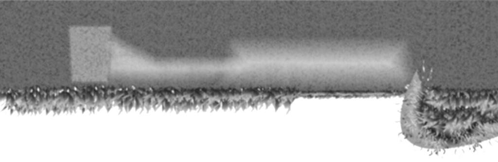
10 Using a flat bladed shovel, define three sides of a square 18 wide by 18 in length and 6 deep. This slit should be U shaped (see figure 3). Work the shovel under the sod at a depth of about 4 inches and roll back the sod leaving exposed soil 3 to 4 inches deep. About 6 inches from one side of this opening, dig a similar opening and hole to accommodate a 7 valve box. This valve box (wiring box) will be used to splice additional wire from the sensor to the zone wire identified in Step 3. Dig a slit trench from the 7 wiring box location to the base of the 18 square opening created for the sensor (see Figure 4). Place the sensor horizontally in the loose soil at the bottom of the U-shaped cavity with the sensor wires running along the trench that leads to the wiring box. Pack loose soil firmly around the sensor rods to a depth of about ½ inch. Then pull the sod back over the sensor and pack it down firmly. 18" 18" 8
11 9
12 Within the wiring box, connect the sensor wires to the extension cable that leads to the valve box. Use grease caps for all connections after confirming proper system operation. If the extension cable wire colors do not match the wire colors from the sensor, write down the extension cable wire colors that correspond to the Red, White and Black wires from the sensor. In the valve box, disconnect the marked zone wire from the valve and connect it to the extension cable wire previously attached to the Red sensor wire. No other wires should be attached to this connection. Re-connect the disconnected valve wire to the Black sensor wire extension. Connect the White sensor wire extension to the common wire in the valve box. Make sure all valves in the valve box share the same common connection with the White sensor wire (see Figure 5). Use grease caps for all connections after confirming proper system operation (see wiring diagram included in your kit). 10

13 Sensor Red Wire Sensor White Wire Controller Zone Wire Controller Common Wire Solenoid Valve Solenoid Valve Sensor Black Wire 11
14 For a weather proof connection (see Figure 6) please use: A 7 inch round Valve Box (Rain Bird item #VB-7RND) Grease Caps or equivalent waterproof connectors (Rain Bird direct bury connector #DBTWC25) Use 18 AWG direct burial polyethylene insulated wire (or equivalent) for splicing and burial Finally, pour a five gallon bucket of water slowly over the sensor installation area. Grease caps 7 round Valve Box To valve box To sensor 18 gauge, direct burial Polyethylene insulated wire 12
15 SMRT-Y User Interface Installation: Overview Mount the SMRT-Y user interface on the wall near the controller. Route the SMRT-Y cable to the controller. Disconnect all wires attached to the common terminal and re-connect them to the White SMRT-Y wire.! NOTE: If there is more than one field common, connect all common wires to the White SMRT-Y wire. Connect the Black SMRT-Y wire to the common terminal on the controller. Disconnect the marked zone wire from its terminal and connect it to the Red SMRT-Y wire. Connect the Green SMRT-Y wire to the terminal from where the zone wire was removed. Connect the Orange SMRT-Y wire to the 24 volt AC hot spot or transformer terminal (see Figure 8). Detailed Procedure Disconnect the wire or wires that are 24V 24V COM connected to the COM (or Common) terminal on your controller. Connect the Black wire from the SMRT-Y user interface to the controller s COM terminal (see Figure 7). Black wire To SMRT-Y Common wire 13
16 Connect the Orange wire from the SMRT-Y to one of the 24 VAC terminals on your controller. In order to determine which of the 24V terminals to connect the Orange wire to, touch the Orange wire to each of them with the controller powered on (AC adapter plugged in). Use the terminal which activates the SMRT-Y display (see Figure 8).! NOTE: Be sure to unplug the power once you determine the correct 24V terminal. Do not disturb the power supply wires connected to these terminals. Leave them connected as they are. Unplug the AC power supply and secure the Orange wire in that terminal along with the existing wire. (Some controllers have a terminal marked TEST or HOT SPOT that can be used to connect the Orange wire.) 14 Be sure to connect the correct 24V terminal 24V 24V COM Orange wire
17 ! NOTE: Some controllers do not provide internal access to the AC power terminals. In this case a 24 volt AC adapter is available at your local sprinkler supply store. You will need to connect one of the AC adapter wires to the COM terminal (which will also have the Black wire from the SMRT-Y attached) and the other adapter wire connects to the Orange wire coming from the SMRT-Y. Connect the wire or wires you disconnected from the COM terminal to the White wire from the SMRT-Y cable using a wire nut (see Figure 9). Disconnect the target zone wire identified and marked earlier (zone #1 in figure 10). Connect it to the Red wire of the SMRT-Y user interface with a wire nut (see Figure 10). 24V 24V COM White Wire wire connector Common wire 24V 24V COM Red wire Hot Wire for the sensor zone 15
18 Connect the Green wire from the SMRT-Y user interface to the zone terminal, where the marked zone wire was originally connected (see Figure 11). Turn on the controller and allow the SMRT-Y user interface to take a soil moisture reading. The reading should appear in the display after 4-5 seconds. If the reading is zero the wiring to the sensor is not correct and will need to be reviewed and corrected. If the reading is not zero, the wiring is correct and you may finish up the grease cap installation on the sensor wiring. Verify soil Temperature and soil Electrical Conductivity as well. Congratulations, you are done with the installation! 16 24V 24V COM Green wire
19 SMRT-Y Operation Take a Moisture Reading The SMRT-Y displays the last moisture reading (taken every 10 minutes). To take a current moisture reading, press Read Sensor. The display will show then, display the current moisture. Set the Moisture Threshold To set the moisture threshold, press and hold Read Sensor then toggle the Soil Temp button to increase the threshold or the Soil EC button to decrease the threshold (see page 23). TEMP. ºF or C HOLD PRESS Read Sensor Soil Temp Soil EC Bypass Sensor VIEW THRESHOLD HOLD INCREASE DECREASE TEMP. ºF or C HOLD PRESS Read Sensor Soil Temp Soil EC Bypass Sensor VIEW THRESHOLD HOLD INCREASE DECREASE HOLD OR 17
20 View Soil Temperature To view the soil temperature, press Soil Temp. Change Temperature Format To change from degree Fahrenheit to Celsius, hold Soil Temp and toggle Soil EC. 18 TEMP. ºF or C HOLD PRESS Read Sensor Soil Temp Soil EC Bypass Sensor VIEW THRESHOLD HOLD INCREASE DECREASE TEMP. ºF or C HOLD PRESS Read Sensor Soil Temp Soil EC Bypass Sensor VIEW THRESHOLD HOLD INCREASE DECREASE HOLD
21 View Soil EC Press Soil EC to view current soil Electrical Conductivity (EC). Manual Watering/Bypass If you wish to test your sprinkler system, or manually water a zone, you will need to bypass the sensor function so that it will not interrupt the power to your valves. In order to do this, press the Bypass Sensor button. The BYPASS SENSOR icon on the display will slowly turn on and off. While in this mode, actions from your controller will not be inhibited by the SMRT-Y user interface. TEMP. ºF or C HOLD PRESS Read Sensor Soil Temp Soil EC Bypass Sensor VIEW THRESHOLD HOLD INCREASE DECREASE TEMP. ºF or C HOLD PRESS Read Sensor Soil Temp Soil EC Bypass Sensor VIEW THRESHOLD HOLD INCREASE DECREASE 19
22 Watering History The SMRT-Y user interface displays the past 7 watering attempts. If the SMRT-Y allowed watering, a drop is displayed. If the system was suspended, it will be blank. Today indicates the most current watering cycle. The history updates 30 minutes after each cycle. Suspending Watering When the moisture in the soil is above the moisture threshold, the Suspended Watering icon appears. Your system will not irrigate. Watering Allowed When the soil moisture is below the moisture threshold, the Watering Allowed icon appears. This icon is also displayed when the BYPASS SENSOR is activated. Your system will irrigate normally. 20
23 Setting the Watering Schedule Field Capacity is the amount of water your soil will hold at equilibrium. The amount of water required to bring the moisture content of the soil from 80% of Field Capacity to 100% of Field Capacity is given by the formula: Inches of water = 0.2 * Field Capacity * depth If your Field Capacity is 25% and you are watering to a depth of 8 inches, then the amount of water needed is 0.2 * 0.25 * 8 = 0.4 inches If you know the effective precipitation rate of your sprinklers, then the watering time is given by: Run time minutes = 60 * Inches / Effective Precipitation Rate If your Effective Precipitation Rate for the example above is 0.5 inches per hour, then the minutes watering time is 60 * 0.4 / 0.5 = 48 minutes. The chart on the next page offers a simple way to set watering times for all zones in your system. It is based on the formulas given above. After you have measured the Field Capacity of your soil (see next page), you can use the chart to find watering times for your zones. You will need to know the type of sprinkler heads installed and their precipitation rates. 21
24 Irrigation Run-time Guide Field Capacity Moisture Threshold Setting Total Run Minutes ROTORS POP-UP SPRAYS ROTARY NOZZLE Soak Time Total Soak Time Total Soak Time Run Soak Run Run Soak Run Run Soak Max. Min. Minutes Max. Min. Minutes Max. Min. 45% 36% % 32% % 28% % 24% % 20% % 16% % 12% % 8% Total Run Minutes is total run time required to bring moisture from the indicated moisture threshold to Field Capacity Soak Time Run Maximum is minutes allowed before surface accumulation causes runoff Soak Time Soak Minimum is minutes of soaking required to absorb surface accumulation. Match your zone sprinkler head type and Field Capacity. If your pop-up sprayer zone has 35% Field Capacity and your moisture threshold is 28%, your total run time is 23 minutes. Set your controller to irrigate a total of 23 minutes, using a soak cycle with a maximum on time of 7 minutes and a minimum soak time of 25 minutes. 22
25 Calculating Field Capacity / Moisture Threshold Each lawn is different. Your Field Capacity and moisture threshold are unique. The following is the best method to determine your ideal moisture threshold setting. Remember that you can adjust your moisture threshold at any time. Field Capacity Method Near sundown, soak the soil to saturation in the area of the sensor. It is important that the area is very wet so that the water is standing on the surface. This can be accomplished with a 5 gallon bucket of water or a garden hose. The next morning, before the direct sunlight reaches the sensor location, take a moisture reading by pressing the Read Sensor button. This reading is your soil s Field Capacity. Your ideal moisture threshold setting should be 80% of Field Capacity. Automatic Moisture Threshold Method Near sundown, soak the soil around the sensor to saturation with a 5 gallon bucket. Set your controller to irrigate at 5:00 am the following morning. Finally, simultaneously press and hold both the Read Sensor and Soil Temp buttons while you depress and release the Soil EC button once. The Suspended Watering mode and Watering Allowed mode will start blinking. When your controller attempts to irrigate the following morning, the SMRT-Y will take a measurement and automatically set your moisture threshold to 80% of Field Capacity. TEMP. ºF or C HOLD PRESS Read Sensor Soil Temp Soil EC VIEW THRESHOLD HOLD INCREASE DECREASE HOLD HOLD Bypass Sensor 23
26 System Setup Set the controller to water all the zones at the highest frequency expected during the peak of the season. This may be every day. Set the zone watering times as they were previously set by the contractor or homeowner. Set the auto-threshold-set feature on the SMRT-Y user interface by simultaneously pressing in and holding the Read Sensor and Soil Temp buttons and then pressing the Soil EC button once. If you have set the feature properly the Suspended icon and Allowed icon will alternately flash. These icons will continue to flash until the threshold has been automatically set. Ensure the controller is set to run the next morning before the sun shines on the sensor area. This interval defines the auto-set period. Ensure Bypass Sensor is not flashing in upper left corner of the LCD display. If flashing, press Bypass Sensor button to allow Soil Moisture Sensor operation. Flood the sensor area with a five gallon bucket of water prior to leaving the property. Also flood the slit trench marks in the sod. Recommended Follow-up The watering moisture threshold is determined during the auto-set period. Sometime after the first controller run, press the Read Sensor button on the SMRT-Y user interface to view the watering moisture threshold. The displayed number is the moisture level in the root zone that will permit irrigation. Re-set the zone run times by referring to the run-time chart and instructions. To use the chart you will need the moisture threshold setting obtained in the previous step and the precipitation rates of the zones. 24
27 Optional wiring for Xeriscape or flower beds You may have zones you wish to water regardless of the moisture level measured by your sensor. For example, a flower bed drip or a desert landscaping zone. The SMRT-Y can accommodate up to two such zones. How to connect them: Identify the zone(s) that fit into this category. Note which terminal(s) they are connected to on your controller. Loosen the screw that connects such zone wire to your controller. Strip the wires and connect the Blue wire from the SMRT-Y user interface to the same terminal as the zone wire.! NOTE: There will now be two wires connected to this terminal; a Blue wire going to the SMRT-Y user interface and a zone wire going to the valve. If you have a second zone to run independently of the moisture sensor, connect the Brown wire from the SMRT-Y user interface to the second terminal. Now these two zones will run independent of moisture sensor. Turn on the controller and allow the SMRT-Y user interface to take a soil moisture reading. The reading should appear in the display after 4-5 seconds. If the reading is zero the wiring to the sensor is not correct and will need to be reviewed and corrected. If the reading is not zero, the wiring is correct and you may finish up the grease cap installation on the sensor wiring. 25
28 Special Notes This Soil Moisture Sensor is compatible with installations using pump start relays. You can use this Soil Moisture Sensor with installations running multiple stations or valves simultaneously. This can be used with a Rain Bird Rain Sensor (part number: RSDBEX). The system will operate as follows: Connect the Rain Sensor to the sensor terminals inside your controller as directed. Connect the SMRT-Y user interface to the controller as described in this manual. When the rain sensor is activated, the common wire will be disrupted and the power to the SMRT-Y user interface may be disabled. If this occurs, the display will go blank and the user interface will cease to function until the rain sensor has dried out. The SMRT-Y programming will not be lost. Even if the user interface was in bypass mode, that mode will be restored when power is reapplied. When power is restored the SMRT-Y user interface will immediately take a moisture reading and set either the Suspended or Allowed mode. The 30 minute timeout requirement will be reset so that the mode change will occur immediately. Long-term exposure to direct sunlight could damage the SMRT-Y LCD display. Use the protective cover (see Figure 12) when installed in direct sunlight. 26

29 SMS Cover 27
30 Troubleshooting Symptom Possible Cause Correction The display is blank. The display shows 00 The power is not connected. The controller is not plugged in. Rain Sensor has been activated The sensor is disconnected. Re-establish power to the SMRT-Y user interface by connecting the Orange wire to the correct 24 VAC terminal on your controller. Plug in the power cord on your controller. Verify if Rain Sensor is activated. Review the SENSOR INSTALLATION section. Check all connections to the sensor and from the SMRT-Y user interface to your controller. The system is not watering. There is no change in the system s watering. Your controller is not set. Be sure your controller is set and running. The soil moisture is not below Take a soil moisture reading. If the reading is above the the moisture threshold setting. threshold, the system should not be watering due to sufficient moisture level. The COM wire is disconnected. The SMRT-Y user interface Green Check the COM wire connection. Check all SMRT-Y user interface wiring. or Red wire is not connected to the correct zone. 28
31 In compliance with European directive 2002/96/CE and nom EN50419:2005, this device must not be thrown away with household garbage. The device must be the object of an appropriate, selective removal procedure in order to recuperate it. Your cooperation will contribute to the respect for the environment and the protection of our natural resources. 29
32 The Intelligent Use Of Water El uso inteligente del agua Pour un usage efficace de l eau Rain Bird Irrigation Corporation Accessories Division 6991 Southpoint Road Tucson, AZ Rain Bird Corporation Registered trademark of Rain Bird Corporation Marca registrada de Rain Bird Corporation Marque commerciale déposée de Rain Bird Corporation 05/09 P/N: Rev. B
HelpAndManual_unregistered_evaluation_copy. SCX User Manual
 HelpAndManual_unregistered_evaluation_copy SCX User Manual Table of Contents SCX Add-On Device Items needed...3 Panel Description...3 How it Works...3 Basic Irrigation Principles Field Capacity...4 Allowable...4
SC6/12 Plus User Manual
 HelpAndManual_illegal_keygen SC6/12 Plus User Manual ACC-SYS-SC6-O ACC-SYS-SC12-O Table of Contents Introduction 4 Moisture...5 Sensor Sensor Site Selection 6...7 Before you Begin...7 Sensor Installation
AUTOMATIC SPRINKLER TIMER
 AUTOMATIC SPRINKLER TIMER Owner s Manual PRT-4 / PRT-6 For use with standard 24 VAC automatic sprinkler valves. These timers are designed for use in any 110 VAC /60 Hz ±10% AC outlet (240 VAC, 50 HZ for
SOIL-CLIK. Soil Moisture System. Owner s Manual and Installation Instructions
 SOIL-CLIK Soil Moisture System Owner s Manual and Installation Instructions Table of Contents Introduction and Installation 3 Specifications 4 Choosing the Probe Location 7 Installing the Soil-Clik Probe
Rain+Birdt. Simple To Set Timer (SST) Setup & Operation Instructions. English RAIN BIRD ( ) or visit
 Setup & Operation Instructions. English RAIN BIRD ( ) or visit") Rain+Birdt Simple To Set r (SST) Setup & Operation Instructions English Installation...2 Tools and Supplies Needed...2 Step 1. Mount r...2 Step 2. Connect Power...2 Indoor r...2 Outdoor r...2 Step 3. Connect
Rain+Birdt Simple To Set r (SST) Setup & Operation Instructions English Installation...2 Tools and Supplies Needed...2 Step 1. Mount r...2 Step 2. Connect Power...2 Indoor r...2 Outdoor r...2 Step 3. Connect
IrriGreen Installation Guide With Diagnostic / Troubleshooting Screens
 IrriGreen Installation Guide With Diagnostic / Troubleshooting Screens Genius Sprinklers Standard Valves READ BEFORE INSTALLATION 1.7.3 Installation Video Irrigreen.com/professionals-logged-in/ Password:
Spray and Rotary Nozzles
 Spray and Rotary Nozzles Introduction Spray Bodies Rotors Valves Controllers Central Controls Landscape Drip Pumps & Filtration Drainage Products Resources Major Products Water Saving Tips HE-VAN nozzles
Spray and Rotary Nozzles
 Introduction Spray Bodies Rotors Valves Controllers Central Controls Landscape Drip Pumps Drainage Products Resources Major Products Water Saving Tips HE-VAN nozzles are fully adjustable from 0 to 360
Application Guide. Rain Bird XPCN Series Xeri Pressure Compensating Nozzle
 Application Guide Rain Bird XPCN Series Xeri Pressure Compensating Nozzle One Nozzle Two Throws With a simple turn of the nozzle to the next preset stop, the Rain Bird XPCN Nozzle adjusts from a 2.5 (0,8
AC Irrigation and Propagation Controllers I Four Station, 5006-I and 5006-IP Six Station
 AC Irrigation and Propagation Controllers 5004-I Four Station, 5006-I and 5006-IP Six Station I N S T R U C T I O N M A N U A L Table of contents Introduction 1 1. Specifications 1 2. Controller Mounting
RAIN BIRD - AQUAGATOR AQUAGATOR INSTALLATION & TROUBLESHOOTING MANUAL
 AQUAGATOR INSTALLATION & TROUBLESHOOTING MANUAL Cozz GT27069-A Revised July 2002 P/N 632360 AQUAGATOR TABLE of CONTENTS DESCRIPTION PAGE INTRODUCTION....... 1 SECTION 1 - PRE-INSTALLATION REQUIREMENTS.
HELP REBATE PROGRAM Healthy and Efficient Landscape Programs. High Efficiency Spray Nozzle/Body/Pressure Regulator Rebate Program Rebate Program
 HELP REBATE PROGRAM Healthy and Efficient Landscape Programs Page 1 High Efficiency Spray Nozzle/Body/Pressure Regulator Rebate Program Rebate Program 5 Easy Steps Step 1 Get informed Santa Clarita Valley
IRRIGATION CONTROLLER
 IRRIGATION CONTROLLER 4 and 6 Station Model INSTRUCTION MANUAL SUITABLE FOR INDOOR USE ONLY OTHERWISE WARRANTY IS VOID N10372 Table Of Contents Features 1 Glossary 2 Programming Instructions Introduction
Smart Wi-Fi Sprinkler Timer and Flow Meters
 Smart Wi-Fi Sprinkler Timer and Flow Meters User s Manual Welcome to H2OPro Thank you for purchasing the H2OPro. The H2OPro is a sprinkler timer with a Wi-Fi interface. The system provides sprinkler valve
i n s t r u c t i o n m a n u a l
 i n s t r u c t i o n m a n u a l 8006 Six-Station AC Timer Residential/Light Commercial Independent Program Irrigation Controllers Installation, Programming and Operating Instructions Features Operates
Installation and Operation
 Installation and Operation v Installation Procedures Indoor Timer Installation... 2 Connecting the Valves... 2 Connecting a Pump Start Relay... 3 Connecting the Plug-in Transformer... 3 Outdoor Timer Installation...
Ezyfit AC Controller INSTRUCTION BOOK 2 & 4 STATION UNITS
 Ezyfit AC Controller INSTRUCTION BOOK 2 & 4 STATION UNITS Features This unit is available in two and four station configurations. Designed for residential applications, this controller has an individual
DIG Corporation Irrigation product Specifications
 DIG Corporation Irrigation product Specifications SECTION 02810 Part 2 Products IRRIGATION SYSTEMS 2.1 Automatic Irrigation Controller [Light][Solar] Irrigation controllers shall be single, solid-state
Installation and User Manual. with RAIN SENSOR.
 with RAIN SENSOR www.solarsmartopener.com Revision..0 TABLE OF CONTENTS Features In The Box Further Items Required Basic Operation Solar Panel and Operator Installation Operator Installation Solar Panel
Instruction Manual MINI IRRIGATION CONTROLLER.
 MINI IRRIGATION CONTROLLER www.krain.com Station Models - Available in 4 OR 6 stations. OUTdoor MODEL - Supplied with 120VAC x 24VAC inbuilt transformer. Optional LEAD with Plug. Instruction Manual Table
TABLE OF CONTENTS YOUR MISTBOX S SERIAL NUMBER
 Mistbox User Guide TABLE OF CONTENTS Introduction... 1 Setup and Installation... 2 Connecting Mistbox to Wi-Fi... 5 Mistbox Operation... 6 Mistbox Maintenance... 8 Mistbox Support... 9 YOUR MISTBOX S SERIAL
Pro-Spray. A rugged contractorfriendly. for residential and commercial projects
 Pro-Spray A rugged contractorfriendly spray for residential and commercial projects The Pro-Spray has been manufactured with the precision required to ensure reliable operation and peak performance for
Sentinel Field Satellite Controller Metal Pedestal, Plastic Pedestal and Wall Mount Models Installation Instructions
 WARNING HIGH VOLTAGE 115V 4 M AP Sentinel Field Satellite Controller Metal Pedestal, Plastic Pedestal and Wall Mount Models Installation Instructions Important: For your protection and the safety of the
Authorized partner Katalog proizvoda.
 Authorized partner 2016 Katalog proizvoda www.naturalist.rs CONTENTS ROTORS MiniPro 2-3 RPS 50 4-5 RPS 75 6-7 RPS 75i 8-9 RPS Select 10-11 ProPlus 12-13 SuperPro 14-15 ProSport 16-17 SPRAYS Pro-S 18-19
570Z Series. Reliability is simply stated in. 570Z Series 20 years of solid. performance. Add to that its. extensive product line offering and
 570Z Series S P R I N K L E R S RESIDENTIAL COMMERCIAL Reliability is simply stated in 570Z Series 20 years of solid performance. Add to that its extensive product line offering and you have a successful
ARC4000e 4 wheel compressor system w / 4 way Ride Pro controller
 350 S. St. Charles St. Jasper, In. 47546 Ph. 812.482.2932 Fax 812.634.6632 on the internet: www.ridetech.com ARC4000e 4 wheel compressor system w / 4 way Ride Pro controller 1 ARC5001 Compressor 1 CON6000
Middle Buster, Sub Soiler, Middle Buster SC
 Middle Buster, Sub Soiler, Hardware Kit 8090000 THANK YOU FOR PURCHASING THIS PRODUCT Congratulations on your purchase. Behlen Country has been in the business of providing quality equipment to landowners
METEOROLOGICAL INSTRUMENTS
 METEOROLOGICAL INSTRUMENTS INSTRUCTIONS PRECIPITATION GAUGE MODEL 50202 / 50203 R.M. YOUNG COMPANY 2801 AERO PARK DRIVE, TRAVERSE CITY, MICHIGAN 49686, USA TEL: (231) 946-3980 FAX: (231) 946-4772 WEB:
WaterGreat LLC. Model SR-1 Series. Installation InstrucTIONS
 Model SR-1 Series Installation InstrucTIONS Copyright 2013 watergreat llc all rights reserved WaterGreat SR-1 TM Installation 1) Attach stake and stainless steel tube [A] to the control assembly [B] and
MODEL SIT -6E PAVEMENT-MOUNTED SNOW AND ICE SENSOR
 MODEL SIT -6E PAVEMENT-MOUNTED SNOW AND ICE SENSOR DESCRIPTION The Snow Switch Model SIT 6E Pavement-Mounted Snow and Ice Sensor reliably detects snow and ice conditions on pavement surfaces when used
DT34 and DT54 Series Rotary Sprinklers
 DT34 and DT54 Series Rotary Sprinklers Installation & Service Instructions Introduction The DT34 and DT54 series full-circle rotary sprinklers are designed specifically for golf course applications. Manufactured
PowerLevel s e r i e s
 Owner s Manual Hydraulic Leveling CONTENTS Introduction Operation Control Panel Automatic Leveling Manual Leveling Retracting Jacks Remote Operation Care & Maintenance Troubleshooting Error Codes 1 2 2
Snow Switch Models HSC 4 (P/N 24220) & HSC 5 (P/N 24221)
 & HSC 5 (P/N 24221)") Description The Snow Switch Model HSC 4 and HSC 5 Pavement-Mounted Deicing Controllers reliably operate snow and ice melting heaters based upon pavement conditions. This ensures that deicing heaters operate
Description The Snow Switch Model HSC 4 and HSC 5 Pavement-Mounted Deicing Controllers reliably operate snow and ice melting heaters based upon pavement conditions. This ensures that deicing heaters operate
5000 Series Rotors 5000, Plus, PRS, SAM
 Tech Spec 5000 Series Rotors 5000, Plus, PRS, SAM Built from top to bottom with the contractor in mind, the Rain Bird 5000 Series product line is the durable, reliable rotor for residential and commercial
Safety & Installation Instructions
 Model 8120A & 8126A Digital Ventilation Controller Safety & Installation Instructions READ AND SAVE THESE INSTRUCTIONS Table of contents Safety Instructions... 3 Specifications... 4 Overview... 4 Mounting
RAM Rail Mount Kit RAM 201UD 5 Arm RAM 2461U Base RAM 235U Base, Double U-Bolt
 Note: Indented items indicate parts included in an assembly listed above. Part Name/Description Part Number Quantity Direct Command Kit 4100514 1 Installation Instructions 2005690 1 CAN Y-Splice 4000137
MINI SKID STEER ATTACHMENT LITERATURE
 MINI SKID STEER ATTACHMENT LITERATURE 2 BUCKETS & BLADES When you need to power through with productivity you can be sure that you ve come to the right place. With our versatile lineup of buckets and blades,
SMRT-Y Soil Moisture Sensor Kit page 131. Medium Flow Commercial Control Zone Kit wih Pressure Regulating, Basket Filter page 202
 New Products www.rainbird.com/newproducts Introducing New Rain Bird Products for 2010 Every new product for 2010 demonstrates Rain Bird s ability to deliver irrigation solutions that enhance your productivity
INSTALLATION INSTRUCTIONS
 RAIN R-50 Series Rotor INSTALLATION INSTRUCTIONS GENERAL INFORMATION The R-50 can be set to full circle (360 ) or part circle operation (25-350 ) without the use of tools. The sprinklers factory preset
FREE INSTALLATION GUIDE. DripMaster. The best way to water plants, trees, shrubs, hanging baskets, and gardens SECTION 2 UP TO 70% WATER SAVINGS
 WAL230561 61100-01 rbqxd 10/27/03 12:32 PM Page 1 CONNECT DRIP TUBING TO OUTSIDE HOSE FAUCET DripMaster SECTION 2 INSTALLATION GUIDE The best way to water plants, trees, shrubs, hanging baskets, and gardens
Sentinel Field Satellite Controller
 WARNING HIGH VOLTAGE 115V M AP Sentinel Field Satellite Controller Installation Instructions Important: For your protection and the safety of the product user, please comply with all Caution and Warning
MODEL HSC-24 AUTOMATIC SNOW/ICE MELTING SYSTEM CONTROL PANEL
 MODEL HSC-24 AUTOMATIC SNOW/ICE MELTING SYSTEM CONTROL PANEL DESCRIPTION The Snow Switch Model HSC-24, 24-volt Pavement-Mounted Snow and Ice Sensor reliably detects snow and ice conditions on pavement
Wireless Temperature/Humidity Station
 Wireless Temperature/Humidity Station Installation Manual For Vantage Pro2 and Vantage Pro2 Plus The Wireless Temperature/Humidity Station, referred to as the Temp/Hum Station in this manual, is for use
Matched Precipitation Rate (MPR) Nozzles
 Nozzles") Tech Spec Matched Precipitation Rate (MPR) Nozzles Primary Application Matched Precipitation Rate (MPR) Nozzles simplify the design process by allowing sprinklers with various arcs and radii to be mixed
Tech Spec Matched Precipitation Rate (MPR) Nozzles Primary Application Matched Precipitation Rate (MPR) Nozzles simplify the design process by allowing sprinklers with various arcs and radii to be mixed
ONBOARD AIR SYSTEM FOR ALL VEHICLES APPLICATIONS
 ONBOARD SYSTEM FOR ALL VEHICLES APPLICATIONS Thank you and congratulations on the purchase of a Pacbrake onboard air system. Please read the manual prior to starting to ensure you can complete the installation
FLEX800 R SERIES CONVERSION UPGRADES
 FLEX800 R SERIES CONVERSION UPGRADES The Toro FLEX800 R Series Conversion Upgrades enable customers with existing Rain Bird Eagle 900 and 1100 Series sprinklers to upgrade to Toro s industry leading sprinkler
Free. Installation Guide. The best way to water plants, trees, shrubs, hanging baskets, and gardens
 Free Installation Guide The best way to water plants, trees, shrubs, hanging baskets, and gardens What is Drip-Irrigation? TABLE OF CONTENTS A Drip-Irrigation system is a watering system designed to apply
ARC4800L Big Red Compressor System
 350 S. St. Charles St. Jasper, In. 47546 Ph. 812.482.2932 Fax 812.634.6632 on the internet: www.ridetech.com ARC4800L Big Red Compressor System 2 ARC7000 ViAir 400C 150psi compressors 2 F9242 5 gallon
DeltaForce System Operation
 DeltaForce System Operation 955294 1 1/2014 Index Precision Planting Warranty and Liability.Page 3 Safety Information Page 4 System Requirements.Page 5 Frequently Asked Questions..Page 6 Hydraulic Fittings..Page
DIY Product Catalog 2015
 DIY Product Catalog 2015 Table of Contents 570Z Pro Series Fixed Spray Sprinklers 3 570 MPR+ Fixed Spray and VAN Sprinkler Nozzles 4 570 Shrub Spray Sprinklers/Bubbler 5 H 2 FLO Precision Series Sprinklers
MICROPROCESSOR CONTROL WATER SUPPLY SYSTEM (MPR-01AW)
") MICROPROCESSOR CONTROL WATER SUPPLY SYSTEM (MPR-01AW) Installation, Operation, and Maintenance Manual REV. "B" REV. "C" PLEASE READ ENTIRE DOCUMENT BEFORE PROCEEDING WITH INSTALLATION Energy Saver has
MICROPROCESSOR CONTROL WATER SUPPLY SYSTEM (MPR-01AW) Installation, Operation, and Maintenance Manual REV. "B" REV. "C" PLEASE READ ENTIRE DOCUMENT BEFORE PROCEEDING WITH INSTALLATION Energy Saver has
DMR 3005 WM ONE ZONE WIRELESS DIMMER RECEIVER
 E363518 DMR 3005 WM ONE ZONE WIRELESS DIMMER RECEIVER 20725 NE. 16 AVE. #A-33 MIAMI, FLORIDA 33179 Tel: (305) 652-2599 Fax: (305) 650-8812 www.lumiron.com Email: sales@lumiron.com 1 Benefits and Features
FLEX /55-6 SERIES GOLF ROTORS
 FLEX800 35-6/55-6 SERIES GOLF ROTORS With the industry s largest selection of high performance nozzles and Trujectory adjustment the New FLEX800 35-6/55-6 Series allows you to put water precisely where
Electric Service Conversion Overhead-to-Underground Xcel Energy Electric Connections. Minnesota North Dakota South Dakota
 Electric Service Conversion Overhead-to-Underground Xcel Energy Electric Connections Page 1 of 7 17-02-420 Electric Service Conversion Overhead-to-Underground Overview and process of converting residential
California Friendly Landscape Training
 California Friendly Landscape Training Irrigation Course Irrigation System Troubleshooting Course originally developed by California Polytechnic State University, San Luis Obispo Irrigation Training &
WeatherTRAK FlowLink Installation Instructions 04/23/2013 Revision 2 HydroPoint Customer Support
 WeatherTRAK FlowLink Installation Instructions 04/23/2013 Revision 2 HydroPoint Customer Support support@hydropoint.com (800) 362-8774 WeatherTRAK FlowLink Installation Instructions Rev 2 1 Introduction
XP-300 Series Sprinklers Installation & Service Instructions
 XP-300 Series Sprinklers Installation & Service Instructions Introduction The XP-300 Series Sprinkler is a multiple-stream gear-driven sprinkler ideal for residential and commercial applications. Sprinkler
BASIC IRRIGATION DESIGN AND TROUBLE SHOOTING TIPS
 BASIC IRRIGATION DESIGN AND TROUBLE SHOOTING TIPS PRESENTED BY NORTHWESTERN SUPPLY, INC. 2054 SANDIFER BLVD. SENECA, SC 29678 864-885-1160 PHONE 864-885-9481 FAX Site Information Measure the outline of
Richdel 300 SERIES MECHANICAL CONTROLLERS INSTALLATION AND OPERATING GUIDE FOR ALL MODELS
 Richdel 300 SERIES MECHANICAL CONTROLLERS INSTALLATION AND OPERATING GUIDE FOR ALL MODELS INSTALLATION INSTRUCTIONS The 300 Series Controllers are operated by electric motors and require 24 volts AC current
The Traveler Series: Adventurer
 The Traveler Series: Adventurer RENOGY 30A Flush Mount Charge Controller Manual 2775 E. Philadelphia St., Ontario, CA 91761 1-800-330-8678 Version: 2.2 Important Safety Instructions Please save these instructions.
Electrical Safety. Electricity. Safety. Division of Workers Compensation HS01-013B(02-14)
") Electrical Safety Electricity Safety Division of Workers Compensation HS01-013B(02-14) Table of Content Respect The Power Of Electricity 3 Inform Your Supervisor Of Faulty Equipment 3 Wear Protective Clothing
Electrical Safety Electricity Safety Division of Workers Compensation HS01-013B(02-14) Table of Content Respect The Power Of Electricity 3 Inform Your Supervisor Of Faulty Equipment 3 Wear Protective Clothing
PF3100 TROUBLESHOOTING SOLUTIONS TO COMMON PROBLEMS. v1.1 Revised Nov 29, 2016
 PF3100 TROUBLESHOOTING SOLUTIONS TO COMMON PROBLEMS v1.1 Revised Table of Contents 1 Common Alarms and Warnings... 1 2 Common Issues... 6 2.1 Communication problems... 6 2.1.1 Controller communication
Pavement-Mounted Deicing Controller SNOW SWITCH MODEL HSC 24. Installation and Operation Manual
 Pavement-Mounted Deicing Controller SNOW SWITCH MODEL HSC 24 MANUAL We Manage Heat Installation and Operation Manual Environmental Technology, Inc. 1850 N Sheridan Street South Bend, Indiana 46628 (574)
i n s t r u c t i o n m a n u a l
 i n s t r u c t i o n m a n u a l 710 & 740 Series Single and Four Station Battery Operated Controllers Features Weekly or cyclical program Four start times per day in weekly mode Irrigation duration from
Operator's Manual IMPORTANT: READ THIS MANUAL AND YOUR TILLER S MANUAL CAREFULLY BEFORE USING THE AEROLLER LAWN AERATOR ATTACHMENT
 Aeroller Converts your garden tiller into a lawn aerator Operator's Manual Model AR388 U.S. Patent No. 6,684,960 and other patents pending IMPORTANT: READ THIS MANUAL AND YOUR TILLER S MANUAL CAREFULLY
DT35 and DT55 Series Rotary Sprinklers Installation & Service Instructions
 O N DT35 and DT55 Series Rotary Sprinklers Installation & Service Instructions Introduction The DT35 and DT55 series adjustable part circle and full circle rotary sprinklers are designed specifically for
Iron Gate Air Pump System Manual
 Iron Gate Air Pump System Manual Installation and Operating Instructions Iron Gate Iron Filter System Manufactured by: R.E Prescott Co., Inc. 10 Railroad Avenue Exeter, New Hampshire 03833 Phone: (603)
DT35 and DT55 Series Rotary Sprinklers Installation & Service Instructions
 O N DT35 and DT55 Series Rotary Sprinklers Installation & Service Instructions Note: For preliminary use only. Introduction The DT35 and DT55 series full-circle/adjustable part-circle rotary sprinklers
i n s t r u c t i o n m a n u a l
 Model 510.xxxP Battery Operated Propagation and Irrigation Controller i n s t r u c t i o n m a n u a l Installation, Programming and Operating Instructions Features Weekly or cyclical program Four start
BATTERY CHARGER Instruction Manual
 BATTERY CHARGER Instruction Manual BEFORE USING OUR BATTERY CHARGER, READ IN DETAILS ALL INSTRUCTIONS CONTAINED IN THIS MANUAL. KEEP THIS MANUAL IN A SAFE PLACE AS YOU MAY NEED TO USE IT AT A LATER DATE.
The Traveler Series TM : Adventurer
 The Traveler Series TM : Adventurer 30A PWM Flush Mount Charge Controller w/ LCD Display 2775 E. Philadelphia St., Ontario, CA 91761 1-800-330-8678 Version: 3.4 Important Safety Instructions Please save
TurfDefender Electronic Leak Detector Kit Reelmaster 5000, 6000 and 5010 Series Traction Units
 Form No. 56 586 Rev A TurfDefender Electronic Leak Detector Kit Reelmaster 5000, 6000 and 500 Series Traction Units Model No. 05 Installation Instructions The Installation Instructions for Reelmaster 5000/6000
PRODUCT INFORMATION. Weather Sensors. The world s most simple, accurate, rugged and reliable rain, freeze and wind sensors S E N T S A R W
 PRODUCT INFORMATION Weather Sensors The world s most simple, accurate, rugged and reliable rain, freeze and wind sensors H E R S E N T S A O E R W S TABLE OF CONTENTS Product Overview...3 Mini-Clik Rain
Sprayer Control. Manual for SprayLink Cable Installations. Tank. Jet Agitator. Agitator Valve. Diaphragm Pump. Pressure Transducer.
 Sprayer Control Plumbing & Installation Manual for SprayLink Cable Installations Tank Jet Tank Shut-Off Diaphragm Pump Electric Ball s Transducer Strainer Relief Regulating Copyrights 2012 TeeJet Technologies.
BRAKE SYSTEM, HYDRAULICALLY ACTUATED - 631G TRACTOR Cat Tractors with standard shoe/drum brakes
 BRAKE SYSTEM, HYDRAULICALLY ACTUATED - 631G TRACTOR 194139 631 Cat Tractors with standard shoe/drum brakes Kress Corporation modifies the Caterpillar tractor air actuated shoe brake system to a hydraulically
PHOTO VOLTAIC CHARGE MODULE MULTI POINT TRACKING
 FEATURES Multi Point Tracking (MPT)/ Pulse Width Modulation (PWM) is a six stage solar charge controller. Drop-in PWM replacement for the PVCM-25D two stage solar charge controller. Works with the PVDM4-LC,
Product Manual Manuel du Produit Manual del Producto
 L Product Manual Manuel du Produit Manual del Producto SOLW2 / SOLW6 / SOLWLR / SOLWH06 / SOLWH12 / SOLWSL2 / SOL30X4 / SOLW88X10 / SOLTRANS88 1.330.274.8317 www.atlanticwatergardens.com Introduction Thank
Automatic Transfer Switch FT-10 Network Control Communications Module (CCM-T) Kit
 Kit") Instruction Sheet 10-2004 Automatic Transfer Switch FT-10 Network Control Communications Module (CCM-T) Kit 541 0811 PURPOSE OF KIT A CCM-T is used to monitor and control an automatic transfer switch.
Instruction Sheet 10-2004 Automatic Transfer Switch FT-10 Network Control Communications Module (CCM-T) Kit 541 0811 PURPOSE OF KIT A CCM-T is used to monitor and control an automatic transfer switch.
Product Manual Manuel du Produit Manual del Producto
 L Product Manual Manuel du Produit Manual del Producto SOLCC2 / SOLCC6 / SOLCCLR / SOLCCH06 / SOLCCH12 / SOLCCSL2 / SOLCCMX3 / SOLCCMX7 / SOLTRANS88 1.330.274.8317 www.atlanticwatergardens.com Introduction
Application Engineering
 Application Engineering February, 2009 Copeland Digital Compressor Controller Introduction The Digital Compressor Controller is the electronics interface between the Copeland Scroll Digital Compressor
i n s t r u c t i o n m a n u a l
 i n s t r u c t i o n m a n u a l Model 510.xxx and 510.xxxS Single-Station Battery Operated Controller Installation, Programming and Operating Instructions Features Weekly or cyclical program Four start
SDS SERIES DC SUBMERISIBLE PUMPS
 SDS SERIES DC SUBMERISIBLE PUMPS INSTALLATION MANUAL Kyocera Solar, Inc. / SOLARJACK, 7812 E. Acoma Drive, Scottsdale, AZ 85260 Telephone (800) 223-9580 FAX (480) 483-6431 E-mail info@kyocerasolar.com
835S/855S SERIES GOLF ROTORS
 835S/855S SERIES GOLF ROTORS With the industry s largest selection of high performance nozzles and Trujectory adjustment the 835S/855S Series allows you to put water precisely where you want it for maximum
INTELLICHLOR SALT CHLORINATOR COMMERCIAL SYSTEM COMSYS-8 (P/N )
") INTELLICHLOR SALT CHLORINATOR COMMERCIAL SYSTEM COMSYS-8 (P/N 520973) INSTALLATION GUIDE IMPORTANT SAFETY INSTRUCTIONS READ AND FOLLOW ALL INSTRUCTIONS SAVE THESE INSTRUCTIONS P/N 520983 Rev. B 1/2016
INTELLICHLOR SALT CHLORINATOR COMMERCIAL SYSTEM COMSYS-8 (P/N 520973) INSTALLATION GUIDE IMPORTANT SAFETY INSTRUCTIONS READ AND FOLLOW ALL INSTRUCTIONS SAVE THESE INSTRUCTIONS P/N 520983 Rev. B 1/2016
Module. Table of Contents. Section 9. Module NOTE: This section applies to applicators with bead or slot modules.
 9-1 Section 9 NOTE: This section applies to applicators with bead or slot modules. Table of Contents... 9-1 Introduction... 9-3 Overview... 9-7 Service... 9-9 Adjusting a ClassicBlue Zero-Cavity... 9-9
ALEX-TRONIX SMART CLOCK TM. BATTERY POWERED TEMPERATURE BUDGETING CONTROLLER MANUAL Patent Pending A DIVISION OF GNA INDUSTRIES, INC.
 ALEX-TRONIX A DIVISION OF GNA INDUSTRIES, INC. SMART CLOCK TM BATTERY POWERED TEMPERATURE BUDGETING CONTROLLER MANUAL Patent Pending M A N U A L INTRODUCTION The Smart Clock is a non-solar battery powered
MP ROTATOR. Design Guide High-Efficiency Multi-Stream Nozzle PILOT SYSTEM DESIGN GUIDE. hunterindustries.com
 MP ROTATOR Design Guide High-Efficiency Multi-Stream Nozzle PILOT SYSTEM DESIGN GUIDE RESIDENTIAL & COMMERCIAL IRRIGATION Built on Innovation hunterindustries.com Product Introduction Reliable Operation
IMPORTANT SAFETY RECOMMENDATIONS
 801-001-01 C IMPORTANT SAFETY RECOMMENDATIONS FAILURE TO COMPLY WITH THE FOLLOWING SAFETY RECOMMENDATIONS MAY RESULT IN SERIOUS PERSONAL INJURY AND/OR PROPERTY DAMAGE. 1. For ADDITIONAL SAFETY we STRONGLY
TC62D Installation Instructions
 TC62D Installation Instructions January 2007 This TC62D has a return water low temperature limit option. Using the low limit precludes using a room sensor because both sensors plug into the same port.
Landscape Irrigation Products
 Landscape Irrigation Products 2013 Catalog The Intelligent Use of Water. New Products www.rainbird.com/newproducts Introducing New Rain Bird Products for 2013 Every new product for 2013 demonstrates Rain
SSP-Series Portable Balances Operation Manual
 SSP-Series Portable Balances Operation Manual TABLE OF CONTENTS SAFETY PRECAUTIONS.. 1 GETTING STARED... 1 INSTALLATION & SET-UP 2 POWER CONNECTION & BATTERY OPERATION... 2 LEVELING... 3 CALIBRATION...
TECHNICAL DATA CAUTION
 Page 1 of 6 1. DESCRIPTION The Viking Model D-2 Accelerator is a quick-opening device, with an integral anti-flood assembly, used to increase the operating speed of a differential type dry pipe valve.
BATTERY CHARGER RS-1000 Instruction Manual
 BATTERY CHARGER RS-1000 Instruction Manual BEFORE USING OUR BATTERY CHARGER RS1000, READ IN DETAILS ALL INSTRUCTIONS CONTAINED IN THIS MANUAL. KEEP THIS MANUAL IN A SAFE PLACE AS YOU MAY NEED TO USE IT
Automatic DC Power Supply/Battery Charger
 Automatic DC Power Supply/Battery Charger PATENTED U.S. 9,270,140; 9,385,556; 9,413,186; 9,509,164 NEW in 2015: Field selectable AC input voltage in high-powered units Automatic battery commissioning mode
Ebling Back Blade Snow Plow Wireless Controller Kit Only sold by SnowplowsPlus.com and ControlAllWireless.com
 Ebling Back Blade Snow Plow Wireless Controller Kit Only sold by SnowplowsPlus.com and ControlAllWireless.com WARNING Always unplug the plow or shut off the battery breaker when in transport or not in
Installation & Calibration
 Installation & Calibration ED2-AT Series SkidWeigh System Lift Truck On-board Check Weighing With Accumulative Load Weight Total ED2-AT Series SkidWeigh V.1.1 General Installation Guide This ED2-AT Series
SmartBoost 50 INSTALLATION INSTRUCTIONS & OWNER S MANUAL LT93 SMTBST50 1. Issue 1 Print 2 AUTOMATIC SHORELINE TRANSFORMER
 SmartBoost 50 AUTOMATIC SHORELINE TRANSFORMER INSTALLATION INSTRUCTIONS & OWNER S MANUAL 1 Contents INTRODUCING... THE SmartBoost 50............................................................ 3 Manual
Installation and Service Instructions
 FLX35-6 & FLX55-6 Series Rotary Sprinklers Installation and Service Instructions Introduction The FLX35-6 and FLX55-6 series full and part circle rotary sprinklers are designed specifically for golf course
180 Lake Ave North Paynesville, MN Phone: MASTER MANUFACTURING 7 BOOM KIT
 180 Lake Ave North Paynesville, MN 56362 Phone: 1-800-864-1649 www.master-mfg.com MASTER MANUFACTURING 7 BOOM KIT Part Number SSBK-7 Rev 3 July. 2014 Note: Do not return product to the distributor/dealer
Application Engineering
 Application Engineering March 2011 Copeland Digital Compressor Controller Introduction The Digital Compressor Controller is the electronics interface between the Copeland Scroll Digital compressor or the