CLORIUSCONTROLS.COM PRODUCT CATALOGUE INDUSTRY. Reliable Flow Controls Since 1902
|
|
|
- Madison Reed
- 5 years ago
- Views:
Transcription


1 CLORIUSCONTROLS.COM PRODUCT CATALOGUE INDUSTRY Reliable Flow Controls Since 1902
2
3 Introduction Control Valves 2 Self-Acting Controls 3 Electronic and Electric Controls 4 Building Automation 5 Pneumatic Controls 6 7 Accessories 8 Quick Choice 9 Applications 10
4
5 Industry - Content Product description Product type Datasheet No. 1. Introduction Section Control valves Section 2 Gun metal valves, threaded ends: 2-way valves, single-seated, DN 15/6-20 L1S way valves, single seated, DN 15-32, balanced L1SB way valves, single-seated, DN 15-25, balanced L1SBR way valves, double-seated, DN L2S way valves, 2 single seats, DN L2F way valves, double-seated, DN 40-50, reverse acting L2SR way valves, 2 single seats, DN L3S Gun metal valves, flanged ends: 3-way valves, 2 single seats, DN L3F way valves, 2 single seats, DN L3FM way valves with slide, DN L3FM-T Cast iron valves, flanged ends: 2-way valves, single-seated, DN 15/4-50 M1F way valves, single-seated, DN 15-80, balanced M1FBN way valves, double-seated, DN M2F way valves, double-seated, DN M2F way valves, double-seated, DN 20-80, reverse acting M2FR way valves, double-seated, DN , reverse acting M2FR way valves, 2 balanced single seats, DN M3F way valves, 2 balanced single seats, DN M3F way valves, 2 single seats, DN M3FM way valves, 2 balanced single seats, DN 150 M3F-I way valves, 2 single seats, DN , ports A-AB interchanged M3FM-I way and 3-way valves, DN 15-40, incl. actuator M1F-FL, M1F-SFL, M3F-FL, M3F-SFL, VB30, VBA Cast steel valves, flanged ends: 2-way valves, single-seated, DN 15/4-50 H1F way valves, single-seated, DN 25-80, balanced H1FB way valves, single-seated, DN 15-80, balanced H1FBN way valves, double-seated, DN H2F way valves, double-seated, DN H2F way valves, 2 balanced single seats, DN H3F way valves, double-seated, DN 20-80, reverse acting H2FR way valves, double-seated, DN , reverse acting H2FR Nodular cast iron valves, flanged ends: 2-way valves, single-seated, DN 15/4-50 G1F way valves, single-seated, DN 25-65, balanced G1FB way valves, single-seated, DN 15-80, balanced G1FBN way valves, double-seated, DN G2F way valves, double-seated, DN G2F way valves, double-seated, DN G2FM way valves, DN G2FM-T way valves, double-seated, DN 20-80, reverse acting G2FR way valves, double-seated, DN , reverse acting G2FR way valves, 2 balanced single seats, DN G3F way valves, 2 balanced single seats, DN G3F way valves, 2 balanced single seats, DN G3FM way valves, 2 balanced single seats, DN G3FM-HT way valves, 2 balanced single seats, DN 200/ G3FM-I way valves, DN G3FM-TR way valves, DN G3FM-TL Control Valves with grooved joints - overview G3CM-T way valves, DN , grooved joints G3CM-T
6 Industry - Content Product description Product type Datasheet No. 3. Self-acting controls Section 3 Temperature controls: 21 good reasons for buying Clorius self-acting temperature controllers Thermostats - overview Thermostats - 200/400/800 N, excl. valves V2, V4, V Thermostats of stainless steel V4.03, V Duostats with double sensor system, excl. valves V4.05, V Pressure controls: Differential Pressure Controls TD Differential Pressure Controls TDS Differential Pressure Controls TDL Differential Pressure Controls TD Differential Pressure Controls TD Differential Pressure Controls TD56-2M Pressure Reducing Valves G1PR, H1PR Electronic and electric controls Section 4 Controllers: Controller ER 2000 ER Controller ER 3000 ER Controller ER 2000-P ER 2000-P Sensors: Temperature sensors FF 12, FF Electric valve actuators: Electric actuator, 1200 N VB, VBA Electric actuator, 1200 N V Analogue actuator, 1200 N AV Marine electric actuator, 1200 N MT90 M Safety set SM Electric actuator for L/M/G3FM-T valves CAR Building automation Section 5 ISC 2100 ISC Pneumatic controls Section 6 Pneumatic actuators S Pneumatic actuators AD, ADHW Pneumatic actuators AS, ASHW Pneumatic-pneumatic positioners PPL, PPR Electro-pneumatic positioners EPL, EPR Pneumatic indicating controllers and transmitters S Filter regulators MC Safety valves Section 7 Safety valves - overview Accessories Section 8 Y strainers Sensor pockets for Clorius thermostats Accessories - cooling units, manual adjusting device Sizing Section 9 Quick Choice of temperature controls Applications Section 10 Evertemper system for hot water control Temperature and pressure controls - Applications Copenhagen,
7 Section 1 Introduction
8

9 CLORIUSCONTROLS.COM COMPANY PROFILE
10 VISION We strive to be a world class advisor and provider of industrial controls 2
11 CONTENT Who we are 4 What guides us 6 Our quality 8 Standards & Certificates 10 Markets served 12 Our products 14 Our clients 16 Sales channels 18 3

12 CLORIUSCONTROLS.COM Who we are The heritage of Clorius Controls goes back to Founded by two Danish brothers Odin and Axel Clorius, the company coenced work on developing and producing a range of self-acting temperature controllers, a line that exists more than a century later. Today, we specialize in development and production of controls for temperature and pressure. For more than a century we have developed our knowledge about monitoring, controlling and regulating heat, cooling and ventilation within offshore, marine, industry, building and utility applications. Understandably, the products and the technology have gone through a dynamic development, and today we offer an up-to-date product range to match our clients need for reliable, economic and user-friendly solutions. Clorius Controls continues to maintain the highest standards for materials and workmanship and our work force remains coitted to carefully upholding the principles of quality and integrity that define the company. We attribute our success to the unique combination of hard work, industry insights, dedication to quality, and in large part, to our culture and values. 4
 Winning takes TALENT to repeat takes character 2004 Establishment of our sales office in")
13 2014 Establishment of our sales office in Singapore and relocation of our HQ near Copenhagen Airport Establishment of our sales representation in India Relocation of our production facilities, from Denmark to Poland Establishment of our sales office in Russia (with our sister company Broen) Winning takes TALENT to repeat takes character 2004 Establishment of our sales office in China 2000 The company changes its name from Odin Controls Systems ApS to 1998 The ownership passes to Aalberts Industries 1994 The company is sold to Raab Karcher Energie Servies GmbH 1983 Introduction of magnetic conductive energy meter 1974 Aquired by ISS Group 1953 Our first exports take place 1902 Foundation of the company as Industri Aktieselskab Clorius, by two Danish brothers, Axel and Odin Clorius. Invention of Clorius first self-acting controller 5
14 CLORIUSCONTROLS.COM MISSION What guides us At Clorius Controls we believe that success comes from teamwork. We apply all our company resources at the service of our customers and partners, from our production facilities, experience and network of experts, to our knowledge, energy and innovative spirit of our people. The Reason For Our Existence Our mission is to build a mutually beneficial partnership with our customers by developing, manufacturing, marketing and servicing products for temperature and pressure control, and regulation of heating and cooling circuits with water, steam or oil as the heat-transferring medium. VISION Where We Want To Go We strive to be a world class advisor and provider of industrial controls. VALUES What We Believe In FLEXIBILITY Global Vision, Local Agility CUSTOMER FOCUS A fundamental ingredient to our success RELIABILITY Keeping our promises QUALITY In our products and excellence in our processes 6


15 Our people are key to our SUCCESS - Experienced, diverse and multi-skilled 7
16 CLORIUSCONTROLS.COM We largely accomplish this through a constant coitment to quality and efficiency. Our quality Since our founding in 1902, quality has been of utmost priority in our production and operations. At Clorius Controls each and every associate knows and lives the purpose of our organization. Providing innovative, industry-leading valves and associated products for controlling the flow and pressure of industrial liquids and steam. The key values that differentiate Clorius Controls is our continuous collaboration with customers, vendors and staff to design and produce the best possible products. We eagerly partner with our customers to develop innovative products and new configurations. We appreciate the recoendations of vendors for better components and improved materials. In exchange, you can count on us for responsive engineering and quick, accoodating production. For our customer this means: Unique and robust design Precise regulation High reliability Low maintenance cost Longer life-cycle Complete documentation 8
17 Our dedication to quality has never been greater. 2 YEAR WARRANTY 9
18 CLORIUSCONTROLS.COM Standards & Certificates Clorius Controls routinely manufactures and tests its products to the most demanding customer specifications and recognized national and international industry standards. A long-standing tradition of delivering to the shipbuilding industry means that products delivered by are developed in order to match the high requirements set by the maritime industry. Since 1993 we have been ISO 9001 certified for development, manufacturing, sales and servicing of controls for buildings, industrial and marine applications. Control valves from Clorius Controls can be delivered with test certificates from all approved Ship Classification Societies: ANSI, DIN, JIS Likewise, we can also deliver valves with certificates in accordance to: EN / 2.1 EN / 2.2 EN / 3.1 Furthermore, we conduct: Inspection and test plan Pressure and leakage test 10

19 11
20 CLORIUSCONTROLS.COM Segments served Clorius Controls products control the flow and pressure of liquids and steam throughout marine and industrial process industries. These include end-users and OEMs in the following segments. Marine & Offshore Oil & Gas Power generation Chemical Pulp & Paper Water treatment Food & Beverage Renewable energy Building & Construction District heating HVAC Food processing Refineries Boiler and heat exchangers Minerals Petrochemical Agriculture Textiles 12


21 13
22 CLORIUSCONTROLS.COM Our products Clorius Controls continually aims to develop our product poftfolio by identifying the needs of the market and providing products and solutions of uncompromised quality. Our product range is divided into 5 different sections, offering an extensive range of equipment for monitoring and control of heating, cooling and ventilation systems. Electric Control Valves Pneumatic Control Valves Self-acting temperature controls Self-acting pressure controls Controlling & Monitoring Clorius valves are the preferred choice of the maritime industries, being installed in more than 1500 vessels within the last five years. Simple, reliable and durable. For a full list of products, do not hesitate to request a copy of our latest product catalog by contacting us or visiting our website. 14
 Thermostat DN15/4-150 Electric Actuator 3 point, analogue Controller ER 2000 (Electric) Sensor PT100 2.")
 Transmitter 24 ma Pneumatic Actuator spring close/open Controller (Pneumatic)")
 Pneumatic Actuator spring close/open Controller (Pneumatic)")
23 Solutions Thermostat DN 15/4-150 Electric Actuator 3 point, analogue Controller ER 2000 (Electric) Sensor PT way valve 2-way valve (DN 15/4-800) Thermostat DN15/4-150 Electric Actuator 3 point, analogue Controller ER 2000 (Electric) Sensor PT way valve 3-way valve (DN ) Electric Actuator 3 point, analogue Controller ER 3000 (Electric) Sensor PT Pressure reducing valve DN way valve (DN ) Transmitter 24 ma Pneumatic Actuator spring close/open Controller (Pneumatic) Transmitter 24 ma Positioner Differential Pressure Controls DN way valve (DN 15/4-800) Pneumatic Actuator spring close/open Controller (Pneumatic) Transmitter 24 ma 9. Positioner 3-way valve DN Pneumatic Actuator spring close/open Controller ER 2000 (Electric) Sensor PT Positioner 3-way valve DN
24 CLORIUSCONTROLS.COM Here are some clients we have recently added to our growing list of partnerships. Our clients We have had the good fortune of being involved with a large number of strong global companies. Our clients are our starting point. They drive everything we do and we work collaboratively with them to achieve results they can measure. Our size enables our specialists to work closely together to develop tailor-made solutions, that meet our clients evolving needs. Alfa Laval Alstom BASF BWSC Doosan Flowserve Gazprom Guangzhou Shipbuilding International Cp., Ltd Hi Air Korea Hyundai Jinling Shipyard Johnson Controls Maersk MAN Diesel & Turbo Saacke Semco Shanghai Shipyard Co., Ltd. Shanghai Waigaoqiao Shipbuilding Co., Ltd. Thermax Yangzijiang Shipbuilding Co., Ltd. Zheijing Ouhua Shipbuilding Co., Ltd. 16

25 Clorius Controls has been a trusted partner for many years, and their equipment has been included in the auxiliary systems for our two-stroke diesel engines during the last 30 years. Furthermore, their service and equipment have been an appreciated part in our systems, at our R&D center. At the beginning of 2013, a new internal cooling water system for our two-stroke diesel engines was developed and was introduced at the end of The new developed cooling water system, the LDCL system, required a special valve design with an extremely low leakage rate between two ports (Control Valve Leakage Classification Class IV). Also provided the significant vibration level from having the valve mounted directly on a diesel engine, robustness was a critical design factor. Clorius Controls took on the project and developed a three-way valve according to all requirements, which was tested with great success and to our full satisfaction. Ole Skeltved Head of Marine Installation Department MAN Diesel & Turbo 17

26 Sales channels Our sales network is there for you in more than 50 countries. Thanks to our sales representation in China, Russia, India, Singapore and Poland, as well as our broad network of distributors, we are available whenever our products or services are required. HEADQUARTERS - DENMARK Kajakvej 4 DK Kastrup Tel.: SALES REPRESENTATION - CHINA Room , Unicom International Tower, No. 547 West Tian Mu Road Shanghai P.R. China SALES REPRESENTATION Cloirus Controls A/S - SINGAPORE SALES REPRESENTATION - INDIA Michael Paschal - Country Head Tlf.: mgp@cloriuscontrols.com 18 SALES REPRESENTATION BROEN Ltd - RUSSIA (sister company) 8-ya Tekstilschikov Street 11/ Moscow Russia Tel.: ext

27 Headquarters Sales representation Distributors SALES REPRESENTATION BROEN SA - POLAND (sister company) ul. Pieszycka Dzierzoniów Poland Tel.: PRODUCTION FACILITIES - POLAND Dzierzionów Poland
28 CLORIUSCONTROLS.COM Kajakvej 4 DK-2770 Kastrup Denmark Phone: Reliable Industrial Controls Since 1902
29
30
31 Section 2 Controls valves
32


33 2-way Control Valves type L1S Gun Metal, PN 16, DN 15/ L GB-1 Characteristics Nominal pressure PN 16 k Regulating capability vs k > 25 vr Single seated and tight closing Quadratic characteristic Applications Regulating valves type L1S are designed for regulating low, medium and high pressure hot water, steam and lubricating oils. The valves are installed combined with temperature or pressure differential regulators in control systems for heating of domestic premises, district heating, industrial processes or marine installations. Dimensioning For sizing of control valves and selection of actuators please see "Quick Choice" leaflet no Design The valve components - spindle, seats and cone - are made of stainless steel. The valve body is made of gun metal RG 5. The thread for the actuator connection is G1B ISO 228. The valves are single seated and designed for tight closure. The leakage rate is less than 0.05% of the full flow (according to VDI/VDE 2174). To obtain an approximate, linear transfer performance, for use in systems with standard existing heat exchangers and pumps, the valve characteristic is made quadratic. Quality assurance All valves are manufactured under an ISO 9001 certification, and are pressure and leakage tested before shipment. Function Without the actuator being connected, the valve is held in open position by means of a spring. With pressure on the spindle the valve will close. In connection with thermostats or electronic actuators, the valves will close at rising temperatures. For cooling circuits a reverse acting valve can be used. The quadratic characteristic will not cease, until the flow has dropped below 4% of the full flow. Technical Data Materials: - valve body Gun metal RG 5 - components Stainless steel Nominal pressure PN 16 Seating Single seated Valve characteristic Quadratic Leakage 0.05% of k vs Temperature range See pressure/temperature diagram Mounting See page 2 Internal connection threads ISO 7/1 Bar 16 15,5 11 Pressure/Temperature Diagram According to DIN 2401 Specifications Type Connection threads DN Opening k vs -value m 3 /h Lifting height Weight kg 15/6 L1S Rp ½ /9 L1S Rp ½ /12 L1S Rp ½ L1S Rp ½ L1S Rp ¾ o C Subject to change without notice.
34 2-way Control Valves type L1S Gun Metal, PN 16, DN 15/ L GB-2 Definition of k vs -value The k vs -value is identical to the IEC flow coefficient k v and defined as the water flow rate in m 3 /h through the fully open valve by a constant differential pressure, p v, of 1 bar. Accessories Manual Adjusting Device Dimension sketch L Mounting The valves can be installed with vertical as well as horizontal spindles. For valve temperatures of max. 170ºC, the thermostat/ actuator can be fitted below or above the valve. For valve temperatures above 170ºC, a cooling unit of type KS 4 has to be applied with connection downwards. The device has a built-in stuffing box. For sealing and manual operation of valves when an actuator has not been fitted, e.g. during periods of construction (max. 170ºC). Cooling Unit KS-4 H1 H G1B d(rp) Strainer It is recoended to use a strainer in front of the regulating valve if the liquid contains suspended particles. Subject to change without notice. Cooling unit protecting the stuffing box of the motor/thermostat. To be applied at valve temperatures between 170ºC and 250ºC. Type L H H1 15/6 L1S Rp ½ 15/9 L1S Rp ½ 15/12 L1S Rp ½ 15 L1S Rp ½ 20 L1S Rp ¾ d


35 2-way Control Valves type L1SB Gun Metal, PN 16, DN H GB-1 Characteristics Nominal pressure PN 16 Regulating capability k vs k vr Single seated, balanced Quadratic characteristic > 25 Applications Control valves type L1SB are de signed for regulation of hot water, steam and lubricating oils. The valves are installed combined with our self-acting thermostats, pressure differential regulators or electric valve actuators for regulation in central heating plants, industrial plants, industrial processes or marine installations. Bar Pressure/Temperature diagram o C Design The valve components - spindle, seats and cone - are made of stainless steel. The valve body is made of gun metal RG 5. The thread for the actuator connection is G1B ISO 228. The valve is single seated, balanced. The leakage rate is less than 0.05% of the full flow (according to VDI/ VDE 2174). Quality assurance All valves are manufactured under an ISO 9001 certification, and are pressure and leakage tested before shipment. Function Without the actuator being connected, the valve is held in open position by means of a spring. With pressure on the spindle the valve will close. In connection with our thermostats the valves will close at rising temperatures. In connection with our electric valve actuators the valves will either close or open depending on the application. The quadratic characteristic will not cease, until the flow has dropped below 4% of the full flow. Technical data Materials: - valve body Gun metal RG 5 - components Stainless steel Nominal pressure PN 16 Seating Single seated Valve characteristic Quadratic Leakage 0.05% of k vs Temperature range See pressure/ temperature diagram Mounting See page 2 Internal connection threads ISO 7/1 Specifications Type Connection threads DN Opening k vs -value m 3 /h Lifting height Weight kg 15 L1SB Rp ½ L1SB Rp ¾ L1SB Rp L1SB Rp 1¼ Subject to change without notice.
36 2-way Control Valves type L1SB Gun Metal, PN 16, DN H GB-2 Definition of k vs -value The k vs -value is identical to the IEC flow coefficient k v and defined as the water flow rate in m 3 /h through the fully open valve by a constant differential pressure, Δp v, of 1 bar. Accessories Manual Adjusting Device Dimension sketch L Mounting Up to 170ºC the valve can be installed vertically as well as horizontally. For media temperature above 170ºC, a cooling unit of type KS-4 has to be applied. It must then be installed with electric actuator/ thermostat downwards. The device has a built-in stuffing box. For sealing and manual operation of valves when an actuator has not been fitted, e.g. during periods of construction (max. 170ºC). Cooling Unit KS-4 H1 H Strainer It is recoended to use a strainer in front of the control valve if the liquid contains suspended particles. Cooling unit protecting the stuffing box of the electric actuator/thermostat. To be applied at valve temperatures between 170ºC and 250ºC. Type L H G1B H1 15 L1SB L1SB L1SB L1SB Dimensioning Type Water / Steam DN 15 Water: Δp L & max. p 1 bar Steam: Δp L & max. p 1 bar DN 20 Water: Δp L & max. p 1 bar Steam: Δp L & max. p 1 bar DN 25 Water: Δp L & max. p 1 bar Steam: Δp L & max. p 1 bar DN 32 Water: Δp L & max. p 1 bar Steam: Δp L & max. p 1 bar p 1 = absolute pressure Thermostats Valve actuators Pressure differential controllers V2 V4 VB/VBA TD66-4 TD Subject to change without notice.
37 Balanced 2-way Control Valves type L1SBR Gun Metal, PN 16, DN 15 32, Reverse acting C GB-1 Characteristics Nominal pressure PN 16 Regulating capability k vs k > 25 vr Single seated, balanced Quadratic characteristic Pressure balanced control valve Applications Balanced control valves type L1SBR are de signed for regulation of cooling water, sea water and lubricating liquids. Balanced valves are used in installations where the system pres su re necessitates a closing for ce greater than available in the actuator pro gram me for a standard sing le sea ted valve, and where the leakage rate for a double-seated valve is unac cep tab le. The valves are installed combined with our self-acting thermostats, pressure differential regulators or electric valve actuators for regulation in central heating plants, industrial plants, industrial processes or marine installations - especially in control systems for cooling. The reverse acting valves are held in closed position by means of a built-in spring. Bar Pressure/Temperature diagram According to DIN 2401 Design The valve components - spindle, seats and cone - are made of stainless steel. The valve body is made of gun metal RG 5. The thread for the actuator connection is G1B ISO 228. The valve is single seated, balanced. The leakage rate is less than 0.05% of the full flow (according to VDI/ VDE 2174). Quality assurance All valves are manufactured under an ISO 9001 certification, and are pressure and leakage tested before shipment. Function Without the actuator being connected, the valve is held in closed position by means of a spring. With pressure on the spindle the valve opens. In connection with our thermostats the valves will open at rising temperatures. In connection with our valve motors the valves will either close or open depending on the application. The quadratic characteristic will not cease, until the flow has dropped below 4% of the full flow. Technical data Materials: - valve body Gun metal RG 5 - components Stainless steel Nominal pressure PN 16 Seating Single seated Valve characteristic Quadratic Leakage 0.05% of k vs Temperature range See pressure/ temperature diagram Mounting See page 2 Internal connection threads ISO 7/1 11 Specifications Type Connection threads DN Opening k vs -value m 3 /h Lifting height Weight kg 15 L1SBR Rp ½ , L1SBR Rp ¾ L1SBR Rp o C 32 L1SBR Rp 1¼ Subject to change without notice.
38 Balanced 2-way Control Valves type L1SBR Gun Metal, PN 16, DN 15 32, Reverse acting C GB-2 Definition of k vs -value The k vs -value is identical to the IEC flow coefficient k v and defined as the water flow rate in m 3 /h through the fully open valve by a constant differential pressure, Δp v, of 1 bar. Accessories Manual Adjusting Device Dimension sketch L Mounting For media temperatures of max. 170ºC, the thermostat/actuator can be fitted below or above the valve. For valve temperatures above 170ºC, a cooling unit of type KS 4 has to be applied and the thermostat/actuator must be fitted below the valve. The device has a built-in stuffing box. For sealing and manual operation of valves when an actuator has not been fitted, e.g. during periods of construction (max. 170ºC). Cooling Unit KS-4 H1 H G1B Strainer It is recoended to use a strainer in front of the control valve if the liquid contains suspended particles. Cooling unit protecting the stuffing box of the motor/thermostat. To be applied at valve temperatures between 170ºC and 250ºC. Type L H H1 15 L1SBR L1SBR L1SBR L1SBR Dimensioning Type DN 15 DN 20 DN 25 DN 32 Water / Steam Water: Δp L & max. p 1 bar Steam: Δp L & max. p 1 bar Water: Δp L & max. p 1 bar Steam: Δp L & max. p 1 bar Water: Δp L & max. p 1 bar Steam: Δp L & max. p 1 bar Water: Δp L & max. p 1 bar Steam: Δp L & max. p 1 bar Thermostats Valve motors Pressure differential controllers V2 V4 VB/VBA TD66-4 TD Subject to change without notice.


39 2-way Control Valves type L2S Gun Metal, PN 16, DN K GB-1 Characteristics Nominal pressure PN 16 k Regulating capability vs k vr Double seated Linear characteristic Applications Control valves type L2S are designed for regulation of hot water and lubricating oils. The valves are installed combined with one of our self-acting thermostats, pressure differential regulators or electric valve actuators for regulation in central heating plants, industrial plants, industrial processes or marine installations. Dimensioning For sizing of control valves and selection of actuators please see "Quick Choice" leaflet no Bar 16 15,5 > 25 Pressure/Temperature Diagram Design The valve body, seats and cone are made of gun metal RG 5. The stem is made of brass. The thread for the actuator connection is G1B ISO 228. The valves are double seated and designed for tight closure.the leakage rate is less than 0.5% of the full flow (according to VDI/VDE 2174). Quality assurance All valves are manufactured under an ISO 9001 certification, and are pressure and leakage tested before shipment. Function Without the actuator being connected, the valve is held in open position by means of a spring. With pressure on the spindle the valve will close. In connection with our thermostats or electric actuators, the valves will close at rising temperatures. For cooling circuits a reverse acting valve can be used. The linear characteristic will not cease, until the flow has dropped below 4% of the full flow. Technical Data Materials: - valve body Gun metal RG 5 - components Gun metal RG 5 - stem Brass Nominal pressure PN 16 Seating Double seated Valve characteristic Linear Leakage 0.5% of k vs Temperature range See pressure/temperature diagram Mounting See page 2 Internal connection threads ISO 7/1 11 Specifications Type Connection threads DN Opening k vs -value m 3 /h Lifting height Weight kg 40 L2S Rp 1½ o C 50 L2S Rp Subject to change without notice.
40 2-way Control Valves type L2S Gun Metal, PN 16, DN K GB-2 Definition of k vs -value The k vs -value is identical to the IEC flow coefficient k v and defined as the water flow rate in m 3 /h through the fully open valve by a constant differential pressure, p v, of 1 bar. Mounting The valves can be installed with vertical as well as horizontal spindles. For valve temperatures of max. 170ºC, the thermostat/actuator can be fitted below or above the valve. For valve temperatures above 170ºC, a cooling unit of type KS 4 has to be applied with connection downwards. Strainer It is recoended to use a strainer in front of the control valve if the liquid contains suspended particles. Accessories Manual Adjusting Device The device has a built-in stuffing box. For sealing and manual operation of valves when an actuator has not been fitted, e.g. during periods of construction (max. 170ºC). Cooling Unit KS-4 Cooling unit protecting the stuffing box of the electric actuator/thermostat. To be applied at valve temperatures between 170ºC and 250ºC. Dimension Sketch Type H1 H L L H G1B H1 40 L2S L2S Subject to change without notice.

 1 (AB) Control valves type L2F are designed for regulating low, medium and high pressure hot water - and cold and hot sea water.")
41 2-way Control Valves type L2F Gun metal, PN 10, DN A GB-1 Characteristics Nominal pressure PN 10 Characteristic almost linear Regulating capability k vs > 25 Two single seats k vr Applications Quality assurance All valves are manufactured under an ISO 9001 certification and are pressure and leakage tested before shipment. For marine applications the valves can be supplied with relevant test certificates from recognized classification societies. 2 (A) 1 (AB) Control valves type L2F are designed for regulating low, medium and high pressure hot water - and cold and hot sea water. The valves are used in connection with one of our temperature regulators in control systems for industrial processes or marine installations. Port Numbering The ports of valves type L2F are marked with the figures 1 and 2. The letters in parentheses refer to the corresponding internationally adapted designations. Dimensioning For sizing of control valves and selection of actuators please see "Quick Choice" leaflet no Design The valve components - valve body, seats, cone and spindle - are made of sea water resistant materials with connection flanges drilled according to DIN The connection thread for the actuator is G1B. 2 (A) 1 (AB) Port 2(A) closes at load on spindle. Function Without the actuator being connected, the valve is held in open position by means of a spring. With pressure on the spindle the valve will close. In connection with our thermostats or electronic actuators, the valves will close at rising temperatures. The linear characteristic will not cease, until the flow has dropped below 4% of the full flow. Technical Data Materials: - Valve body, seats and cone CuSn5Zn5Pb5-C - Spindle W.no Nominal pressure PN 10 Seating 2 balanced seats Valve characteristic Almost linear Leakage 0.5% of k vs Temperature range See pressure/temperature diagram Mounting With spindle vertical Flanges drilled according to DIN Bar 10 Pressure/Temperature diagram According to DIN Not to be used C Specification Type Flange connection DN in Opening k vs -value m 3 /h Lifting height Weight 65 L2F L2F L2F L2F L2F kg Subject to changes without notice.
42 2-way Control Valves type L2F Gun metal, PN 10, DN A GB-2 Definition of k vs -value The k vs -value is identical to the IEC flow coefficient k v and defined as the water flow rate in m 3 /h through the fully open valve by a constant differential pressure, Δp v, of 1 bar. Dimensions b L L1 Mounting d The valves can be installed with vertical as well as horizontal spindles. The valves must be mounted in a way that the valve motor will be exposed to a minimum of moisture and unnecessary vibrations. D 1 2 k H1 H Strainer It is recoended to use a strainer in front of the control valve if the liquid contains suspended particles. G1B Accessories Manual adjusting device The device has a built-in stuffing box. For tightening and manual operation of valves when an actuator has not been fitted, e.g. during periods of construction (max. 170ºC). Type L L1 H H1 D (dia.) b k (dia.) d dia. (number) 65 L2F x(4) 80 L2F x(8) 100 L2F x(8) 125 L2F x(8) 150 L2F x(8) Subject to changes without notice.
 For cooling water and lubricants Linear characteristic Applications Valves type L2SR are mainly intended for control of cooling water, sea water and lubricating liquids.")
43 2-way Control Valves type L2SR, Gun metal PN 16, DN 40 50, 2 seats, Reverse acting L GB-1 Characteristics Nominel pressure PN 16 Regulating capability k vs > 25 k vr Reverse acting (normally closed) For cooling water and lubricants Linear characteristic Applications Valves type L2SR are mainly intended for control of cooling water, sea water and lubricating liquids. The valves are used in conjunction with temperature- or pressure dif ferential regulators in industrial processes or marine installations - especially in control systems for cooling. As the reverse acting valves are held in closed position by means of a builtin spring, the max. differential pressure, p L, against which a valve can close depends on the spring and when opening the valve, the actuator has to overcome the spring force. Bar Pressure/Temperature Diagram C Please find the below max. allowable values of p L as well as the max. allowable inlet pressures for opening the valves, p 1max, for various actuator forces. Dimensioning For sizing of control valves and selection of actuators please see Quick Choice datasheet no Design The valve body, seats and cone are made of gun metal RG 5 and the stem of stainless steel the valve body with threaded ends according to ISO 7-1. The thread for the actuator connection is G1B. The valves are double-seated and designed for tight closure. The leakage rate is less than 0.5% of the full flow (according to VDI/VDE 2174). Quality Assurance All valves are manufactured under an ISO 9001 certification, and are pressure and leakage tested before shipment. Function Reverse Acting Without an actuator being connected, the valve is held in closed position by means of a spring. With pressure on the spindle the valve opens. In connection with thermostats or electric valve actuators the valves act as cooling valves, i.e. they open at rising temperatures. Technical Data Materials: - Valve, body, seats and cone Gun metal RG 5 W.No Stem Stainless Steel W.No Nominal pressure PN 16 Seating Double seated Flow characteristic Linear Regulating capability k vs > 25 Leakage rate Temperature range k vr 0.5% of k vs See pressure/ temperature diagram Mounting See page 2 Connection threads ISO 7-1 Specifications Type Connection Opening dia. k vs -value Rated Travel Max. p L Actuator Force Corresp. p 1max Weight R P m 3 /h bar N bar kg 40 L2SR 1 ½" L2SR 2" Subject to change without notice.
44 2-way Control Valves type L2SR, Gun metal PN 16, DN 40 50, 2 seats, Reverse acting L GB-2 Definition of k vs -value The k vs -value is identical to the IEC flow coefficient k v and defined as the water flow rate in m 3 /h through the fully open valve by a constant differential pressure, p v, of 1 bar. Mounting The valves can be installed with vertical as well as horisontal spind les. For valve temperatures of max. 170ºC, the thermostat/actuator can be fitted below or above the valve. For valve temperatures above 170ºC, a cooling unit of type KS4 has to be applied with connection downwards. Strainer It is recoended to use a strainer in front of the regulating valve if the liquid contains suspended particles. Accessories Manual Adjusting Device The device has a built-in stuffing box. For tightening and manual ope ration of valves when an actuator has not been fitted, e.g. during periods of construction (max. 170ºC). Cooling Unit KS-4 Cooling unit protecting the stuffing box of the electric actuator/thermostat. To be applied at valve temperatures be tween 170ºC and 250ºC. Dimension Sketch H H1 Type L L H G1B H1 40 L2SR L2SR Subject to change without notice.

 1 (AB) Applications Control valves type L3S are designed for regulating fresh water, cold and hot seawater and lubricating liquids.")
45 3-way Control Valves type L3S Gun metal, PN 10, DN J GB-1 Characteristics Nominal pressure PN 10 Characteristic almost linear Regulating capability k vs > 25 Two single seats k vr Quality assurance All valves are manufactured under an ISO 9001 certification and are pressure and leakage tested before shipment. DN (A) 1 (AB) Applications Control valves type L3S are designed for regulating fresh water, cold and hot seawater and lubricating liquids. The valves are used in conjunction with temperature regulators in control systems for heating of domestic premises, district heating, industrial processes or marine installations. Port numbering The ports of valves type L3S are marked with the figures 1, 2 and 3. The letters in parentheses refer to the corresponding internationally adapted designations. Mixing valve 2 (A) 1 (AB) Diverting valve 2 (A) 1 (AB) DN (B) 3 (B) Dimensioning For sizing of control valves and selection of actuators please see "Quick Choice" leaflet no Design The valve components - valve body, seats and cone - are made of sea-water resistant gun metal RG 5. The valves are single seated and designed for tight closure. The leakage rate is less than 0.5% of the full flow (according to VDI/VDE 2174). Note: The design of the sizes DN 15 (½ ) and DN 20 (¾ ) is different from the bigger ones. Port 1(AB) Port 2(A) Port 3(B) Function 3 (B) 3 (B) coon port always open closes at load on spindle opens at load on spindle Without an actuator being installed, connection 2-1 is fully open and connection 3-1 completely closed by means of a spring. On increasing pressure on the spindle, the opening of the ports changes proportionally to the travel of the spindle, and when the spindle is pressed to the bottom, connection 3-1 is fully open and connection 2-1 completely closed. 2 (A) Technical data Materials: - Valve body, seats and cone Gun metal RG 5 Nominal pressure Seating Valve characteristic Leakage rate Way of operation PN 10 (max. 120ºC) Two single seats unbalanced balanced Almost linear 0.5% of k vs When spindle is actuated: Gate 1-2 closes Gate 1-3 opens Mounting See page 2 Internal connection threads ISO 7/1 1 (AB) Bar Pressure/Temperature diagram According to DIN Not to be used C Specification Type Connection threads DN Opening k vs -value mixing valve m 3 /h k vs -value diverting valve m 3 /h Lifting height 15 L3S Rp ½ L3S Rp ¾ Weight 25 L3S Rp L3S Rp 1¼ L3S Rp 1½ L3S Rp kg Subject to changes without notice.
46 3-way Control Valves type L3S Gun metal, PN 10, DN J GB-2 Definition of k vs -value The k vs -value is identical to the IEC flow coefficient k v and defined as the water flow rate in m 3 /h through the fully open valve by a constant differential pressure, Δp v, of 1 bar. Dimension sketch L 3 Mounting The valves can be installed with vertical as well as horisontal spindles. The thermo-stat/actuator can be fitted below or above the valve. DN H1 H 2 1 G1B Strainer It is recoended to use a strainer in front of the control valve if the liquid contains suspended particles. L L1 Accessories Manual Adjusting Device DN H1 The device has a built-in stuffing box. For tightening and manual operation of valves when an actuator has not been fitted, e.g. during periods of construction (max. 170ºC). G1B H Type L L1 H H1 Subject to changes without notice. 15 L3S L3S L3S L3S L3S L3S

47 3-way Control Valves type L3F Gun metal, PN 10, DN K GB-1 Characteristics Nominal pressure PN 10 Characteristic almost linear Regulating capability k vs > 25 Two single seats k vr Applications Control valves type L3F are designed for regulating low, medium and high pressure hot water - and cold and hot sea water. The valves are used in connection with one of our temperature regulators in control systems for industrial processes or marine installations. Dimensioning For sizing of control valves and selection of actuators please see "Quick Choice" leaflet no Design The valve components - valve body, seats, cone and spindle - are made of sea water resistant materials with connection flanges drilled according to DIN The connection thread for the actuator is G1B. Quality assurance All valves are manufactured under an ISO 9001 certification and are pressure and leakage tested before shipment. For marine applications the valves can be supplied with relevant test certificates from recognized classification societies. Port Numbering The ports of valves type L3F are marked with the figures 1, 2 and 3. The letters in parentheses refer to the corresponding internationally adapted designations. Mixing valve 2 (A) Port 1(AB) Port 2(A) Port 3(B) Function 3 (B) 1 (AB) Diverting valve 2 (A) 3 (B) 1 (AB) coon port always open closes at load on spindle opens at load on spindle Without an actuator being installed, connection 2-1 is fully open and connection 3-1 completely closed, by means of a spring. By increasing pressure on the spindle, the opening of the ports changes 2 (A) 3 (B) 1 (AB) proportionally to the travel of the spindle, and when the spindle is pressed to the bottom, connection 3-1 is fully open and connection 2-1 completely closed. Technical Data Materials: - Valve body, seats and cone CuSn5Zn5Pb5-C - Spindle W.no Nominal pressure PN 10 Seating 2 balanced seats Valve characteristic Almost linear Leakage 0.5% of k vs Temperature range See pressure/temperature diagram Mounting With spindle vertical Flanges drilled according to DIN Bar 10 Pressure/Temperature diagram According to DIN Not to be used C Specification Type Flange connection DN in Opening Mixing valve k vs -value m 3 /h Diverting valve k vs -value m 3 /h Lifting height Weight 65 L3F L3F L3F L3F L3F kg Subject to changes without notice.
48 3-way Control Valves type L3F Gun metal, PN 10, DN K GB-2 Definition of k vs -value The k vs -value is identical to the IEC flow coefficient k v and defined as the water flow rate in m 3 /h through the fully open valve by a constant differential pressure, Δp v, of 1 bar. Dimensions L L1 b Important note In case the valves are applied as diverting valves, the pressure drop will increase by 35% and the k vs -value will decrease by 14% as against mixing valves. D k H1 d k H Mounting The valves can be installed with vertical as well as horizontal spindles. The valves must be mounted in a way that the valve motor will be exposed to a minimum of moisture and unnecessary vibrations. Free height above / below the valve must be minimum 645 for mounting and operation of the MT90 Marine motor. See drawing. Type L G1B L1 H H1 D (dia.) b k (dia.) d dia. (number) Strainer It is recoended to use a strainer in front of the control valve if the liquid contains suspended particles. 65 L3F x(4) 80 L3F x(8) 100 L3F x(8) 125 L3F x(8) 150 L3F x(8) Accessories Manual adjusting device The device has a built-in stuffing box. For tightening and manual operation of valves when an actuator has not been fitted, e.g. during periods of construction (max. 170ºC). Subject to changes without notice.

49 3-way control valves type L3FM, Gun metal PN 10, DN / PN 6, DN 300/ L GB-1 Characteristics Nominal pressure : PN 10 max. 120 C 300/ : PN 6 max. 120 C Regulating capability k vs k > 25 Two single seats vr For cooling and heating purposes Sea water resistant Port numbering The ports of valves type L3FM are marked with the letters AB, A and B. Mixing valve A M AB Diverting valve A M AB A (2) AB (1) Applications Control valve type L3FM is designed for regulating of sea water. The valves are used in conjunction with marine instal lations, e.g. cooling of main and auxiliary engines. Designed for use in conjunction with Clorius valve motor type MT90 Marine. Dimensioning For sizing of control valves up to DN 150 please see Quick Choice leaflet No For sizing of control valves bigger than DN 150 the following equation can be used: k vs 3 G(m / h) = p(bar) 3 G(m / h) p(bar) = k vs Please see data sheet , for max. differential pressure which the actuator type MT90 Marine, can close the valve against. Design The valve components (seats and cone) are made of gun metal, the spindle of stainless steel. The valve body is made of gun metal and the valve flanges are drilled according to DIN Quality assurance All valves are manufactured under an ISO 9001 certification, and are pressure and leakage tested before shipment. For marine applications the valves can be supplied with relevant test certificates from recognized classification societies. 2 Port AB Port A Port B B coon port always open closes at load on spindle opens at load on spindle Function The valve cone is firmly connected with the motor spindle. When the valve cone is in the one outer position by draw on the spindle, connection A-AB is kept fully open and connection B-AB is fully closed. In the other outer position connection A-AB is fully closed and connection B-AB is fully open. In the intermediate positions the opening degrees change proportionally. Technical data Materials - Valve body Gun metal RG 5 CuSn5Zn5Pb5-C - Trim Gun metal RG 5 CuSn5Zn5Pb5-C - Valve spindle Stainless steel (W.no ) Nominal pressure DN : PN 10 (max. 120 C) DN 300/ : PN 6 (max. 120 C) Seats 2 balanced single seats Valve characteristic Almost linear Leakage < 0.5% Temperature range Max. 120 C Mounting See page 2 Flanges According to DIN Note! Valve type 300/250 L3FM has outer measures and flanges drilled as valve type 300 L3FM B Pressure/Temperature Diagram Bar Bar B (3) PN 10 DN Not to be used Not to be used o C PN 6 DN 300/ Subject to change without notice. 300 o C
50 3-way control valves type L3FM, Gun metal PN 10, DN / PN 6, DN 300/ L GB-2 Definition of k vs -value The k vs -value is identical to the IEC flow coefficient k v and defined as the water flow rate in m 3 /h through the fully open valve by a constant differential pressure, p v, of 1 bar. Important note: In case the valves are applied as diverting valves, the pressure drop will increase by 35% and the k vs -value will decrease by 14% as against mixing valves. Specifications Type Flange connection DN in Opening k vs -value 1) m 3 /h Lifting height Weight kg 80 L3FM L3FM L3FM L3FM /175 L3FM L3FM /250 L3FM 2) L3FM ) The stated k vs values apply for mixing valves. Diverting valves: 0.86 x (k vs -values for mixing valves). 2) Valve type 300/250 L3FM has outer measures and flanges drilled as type 300 L3FM. Mounting The valves can be installed vertical as well as horizontal. The valves must be mounted in a way that the valve motor will be exposed to a minimum of moisture and unnecessary vibrations. Free height above / below the valve must be minimum 645 for mounting and operation of the MT90 Marine motor. See drawing. Dimensions Strainer It is recoended to use a strainer in front of the control valve if the liquid contains suspended particles. Type L L1 H H1 b D (dia.) k (dia.) d dia. (number) 80 L3FM x(8) 100 L3FM x(8) 125 L3FM x(8) 150 L3FM x(8) 200/175 L3FM x(8) 200 L3FM x(8) 300/250 L3FM 2) x(12) 300 L3FM x(12) Subject to change without notice. 2) Valve type 300/250 L3FM has outer measures and flanges drilled as type 300 L3FM.
 350-600 L3FM-T: PN 6, max.")
51 3-way Control Valves type L3FM-T Gun metal, PN 10, DN / PN 6, DN C GB-1 Characteristics Nominal pressure L3FM-T: PN 10, max.100 C (option 120 C) L3FM-T: PN 6, max. 100 C (option 120 C) Slide in gun metal Quality assurance All valves are manufactured under an ISO 9001 certification, and are pressure and leakage tested before shipment. For marine applications the valves can be supplied with relevant test certificates from recognized classification societies. A Applications Control valve type L3FM-T is a three-way control valve with a slide for quarter turn operation designed for regulating of sea water. The valves are designed for use in conjunction with valve motor type RCEL with handle for manual operation or for use in conjunction with a pneumatic actuator. Dimensioning For sizing of control valves the following equation can be used: k Design vs 3 G(m / h) = p(bar) 3 G(m / h) p(bar) = k vs The valve body and the valve slide are made of gun metal. The valve flanges are drilled according to EN Function The slide is firmly connected with the motor spindle. When the slide is in the one extreme position by turning the spindle, connection A-AB is kept fully open and connection B-AB is fully closed. In the other extreme position connection A-AB is fully closed and connection B-AB is fully open. In the intermediate positions the opening degrees change proportionally. The valve has a small tolerance between body and slide. To minimize the leakage an O-ring is mounted in a groove on the slide. Technical data Materials: - Valve body Gun metal RG 5 CuSn5Zn5Pb5-C - Slide CuAl10Fe5Ni5 - O-ring NBR 70A Nominal pressure: L3FM-T PN L3FM-T PN 6 Specifications Type Flange connection DN in k vs -value 1) Mixing valve m 3 /h Valve characteristic Almost linear Leakage Max. 0.5% Temperature range Max. 100 C (option 120 C) Mounting See page 2 Flanges EN PN 6/10 Counter flanges (suggested) DIN 2632 PN 6 DIN 2633 PN 10 Max. pressure p L, against which the control can close: L3FM-T 10 bar L3FM-T 6 bar k vs -value 1) Diverting valve m 3 /h Torque Nm Weight kg 200 L3FM-T L3FM-T L3FM-T L3FM-T L3FM-T L3FM-T L3FM-T L3FM-T 2) ) k vs -value for port A and B 50% open. 2) Preliminary specifications B AB Port numbering / Configuration Mixing Diverting A AB AB A A AB AB A B B B B AB-Right AB-Left AB-Right AB-Left Further specification for ordering (e.g. 400 L3FM-T, AB-Right) Subject to change without notice.
52 3-way Control Valves type L3FM-T Gun metal, PN 10, DN / PN 6, DN C GB-2 Pressure/Temperature diagram Dimension sketch Bar 10 PN Not to be used o C L1 Bar 16 PN b 150 Not to be used o C C d Definition of k vs -value The k vs -value is identical to the IEC flow coefficient k v and defined as the water flow rate in m 3 /h through the fully open valve by a constant differential pressure, p v, of 1 bar. H k D H1 Mounting The valve connections are marked A, B and AB. The slide is operating between A and B. Check slide position before installation in the pipe. The slide position is marked on the top of the shaft. Valve can be supplied in two different configurations, AB-Right and AB-Left. Please note that the supplied configuration is according to installation. The valves can be installed with vertical as well as horizontal spindles. The valves must be mounted in a way that the valve actuator will be exposed to a minimum of moisture and unnecessary vibrations. Strainer It is recoended to use a strainer in front of the control valve if the liquid contains suspended particles. Type L L1 H H1 b C D (dia.) k (dia.) d dia. (number) 200 L3FM-T x (8) 250 L3FM-T x (12) 300 L3FM-T x (12) 350 L3FM-T x (12) 400 L3FM-T x (16) 450 L3FM-T x (16) 500 L3FM-T x (20) 600 L3FM-T 2) x (20) 2) Preliminary dimensions L Subject to change without notice.

53 2-way Control Valves type M1F Cast iron, PN 16, DN 15/ L GB-1 Characteristics Nominal pressure PN 16 Regulating capability k vs k vr Single-seated, tightly closing Quadratic characteristic > 25 Applications Control valves type M1F are designed for regulating low, medium and high pressure hot water, steam and lubricating oils. The valves are used in conjunction with our temperature or pressure differential regulators for controlling industrial processes, district or central heating plants or marine installations. Dimensioning For sizing of control valves and selection of actuators, please see "Quick Choice" leaflet no Design The valve components - spindle, seat and cone - are made of stainless steel. The valve body is made of cast iron EN-GJS with flanges drilled according to EN The thread for the actuator connection is G1B ISO 228. The valves are single-seated and designed for tight closure. The leakage rate is less than 0.05% of the full flow (according to VDI/VDE 2174). Quality assurance All valves are manufactured under an ISO 9001 certification and are pressure and leakage tested before shipment. Function Without the actuator being connected, the valve is held in open position by means of a spring. With pressure on the spindle the valve will close. In connection with our thermostats or electronic actuators, the valves will close at rising temperatures. For cooling circuits a reverse acting valve can be used. The quadratic characteristic will not cease until the flow has dropped below 4% of the full flow. Technical data Materials: - Valve body Cast iron EN-GJS Components Stainless steel - Bolts, nuts 24 CrMo 4/A4 Nominal pressure PN 16 Seating Single-seated Valve characteristic Quadratic Regulating capability k vs > 25 k vr Seat leakage 0.05% of k vs Temperature range See diagram Mounting See page 2 Flanged ends drilled according to EN PN 16 Counter flanges DIN 2633/BS 4504 Colour Grey Bar Pressure/Temperature diagram C Specifications Type Flange connection DN in Opening k vs -value m 3 /h Lifting height Weight kg 15/4 M1F /6 M1F /9 M1F /12 M1F M1F M1F M1F M1F M1F M1F Subject to changes without notice.
54 2-way Control Valves type M1F Cast iron, PN 16, DN 15/ L GB-2 Definition of k vs -value The k vs -value is identical to the IEC flow coefficient k v and defined as the water flow rate in m 3 /h through the fully open valve by a constant differential pressure, p v, of 1 bar. Dimension sketch b G1B Mounting H1 Up to 170ºC the valve can be installed vertically as well as horizontally. For media temperature above 170ºC, a cooling unit of type KS has to be applied. It must then be installed with actuator/ thermostats downwards, and according to the following instructions: D k d H2 Valve Cooling Suitable Temperature Unit for 170ºC - 250ºC KS-4 All actuators 250ºC - 300ºC KS-5 Thermostats 250ºC - 300ºC KS-6 Valve Motors Strainer It is recoended to use a strainer in front of the control valve if the liquid contains suspended particles. Accessories Manual Adjusting Device Type L H1 H2 L b D (dia.) k (dia.) d dia. (number) 15/4 M1F x (4) 15/6 M1F x (4) 15/9 M1F x (4) 15/12 M1F x (4) 15 M1F x (4) 20 M1F x (4) 25 M1F x (4) 32 M1F x (4) 40 M1F x (4) 50 M1F x (4) The device has a built-in stuffing box. For sealing and manual operation of valves when an actuator has not been fitted, e.g. during periods of construction. Cooling Unit KS-4 Cooling Unit KS-5 Cooling Unit KS-6 Cooling unit protecting the stuffing box of the motor/thermostat. To be applied at valve temperatures between 170ºC and 250ºC. Cooling units with built-in bellow glands, replacing stuffing box of thermostat (KS-5) or valve motor (KS-6). Must be applied at valve temperatures above 250ºC. Subject to changes without notice.
55 Balanced 2-way Control Valves type M1FBN Cast iron, PN 16, DN C GB-1 Characteristics Nominal pressure PN 16 Pressure balanced valve Regulating capability k vs k vr Single-seated, balanced Quadratic characteristic > 25 Applications Balanced control valves type M1FBN are designed for regulating hot water, steam and hot oil systems. Balanced valves are used in installations where the system pressure necessitates a closing force greater than available in the actuator prograe for a standard single seated valve, and where the leakage rate for a double-seated valve is unacceptable. The valves are used in conjunction with our temperature- or pressure differential regulators for controlling industrial processes, district or central heating plants or marine installations. Design The valve components - spindle, seat, cone - are made of stainless steel. Pressure/Temperature diagram Bar Specifications Type Flange connection DN in 250 o C Opening The valve body is made of cast iron EN GJS with flanges drilled according to EN or ANSI B16.5 Class 150. The thread for the actuator connection is G1B ISO 228. The valves are single-seated and de signed for tight closure. The leakage rate is less than 0.05% of the full flow (according to VDI/VDE 2174). Quality assurance All valves are manufactured under an ISO 9001 certification and are pressure and leakage tested before shipment. For marine applications the valves can be supplied with relevant test certificates from recognized classification societies. Function Without an actuator being connected, the valve is held in open position by means of a spring. With force on the spindle the valve will close. In connection with our thermostats or electric actuators, the valves will close at rising temperatures. For cooling circuits a reverse acting double-seated valve can be used. The quadratic characteristic will not cease until the flow has dropped below 4% of the full flow. Technical data Materials: - Valve body Cast iron EN GJS Components Stainless steel - Nuts, bolts 24 CrMo 5/A4 Nominal pressure PN 16 Seating Single-seated Valve characteristic Quadratic Regulating capability k vs k vs -value m 3 /h k vr Lifting height > 25 Weight kg Leakage 0.05% of k vs Temperature range See pressure/temperature diagram Flanges drilled according to EN PN 16 or ANSI B16.5 Class 150 Colour Grey Definition of k vs -value The k vs -value is identical to the IEC flow coefficient k v and defined as the water flow rate in m 3 /h through the fully open valve by a constant differential pressure, p v, of 1 bar. Mounting Up to 170ºC the valve can be installed vertically as well as horizontally. For media temperature above 170ºC, a cooling unit of type KS-4 has to be applied. It must then be installed with electric actuator/ thermostat downwards. Strainer It is recoended to use a strainer in front of the control valve if the liquid contains suspended particles. 15 M1FBN M1FBN M1FBN M1FBN M1FBN M1FBN M1FBN M1FBN Subject to changes without notice.
56 Balanced 2-way Control Valves type M1FBN Cast iron, PN 16, DN C GB-2 Accessories Manual adjusting device Dimension sketch L d The device has a built-in stuffing box. For sealing and manual operation of valves when an actuator has not been fitted, e.g. during periods of construction. H1 k D Cooling unit KS-4 H b Cooling unit protecting the stuffing box of the electric actuator / thermostat. To be applied at valve temperatures between 170ºC and 250ºC. Dimensions Type L H H1 G1B D (dia.) b k (dia.) d dia. (number) 15 M1FBN x(4) 20 M1FBN x(4) 25 M1FBN x(4) 32 M1FBN x(4) 40 M1FBN x(4) 50 M1FBN x(4) 65 M1FBN x(4) 80 M1FBN x(8) Dimensioning Type Water / Steam Thermostats Valve actuators Pressure differential controllers V2 V4 V8 V / AV VB / VBA TD66-4 TD M1FBN Water: p & max. p bar L 1 10 Steam: p L & max. p 1 bar 9 20 M1FBN Water: p & max. p bar 9 L 1 Steam: p L & max. p 1 bar M1FBN Water: p & max. p bar 8 L 1 Steam: p L & max. p 1 bar M1FBN Water: p & max. p bar 7 L 1 Steam: p L & max. p 1 bar M1FBN Water: p & max. p bar L Steam: p L & max. p 1 bar M1FBN Water: p & max. p bar L 1 Steam: p L & max. p 1 bar M1FBN Water: p & max. p bar L 1 Steam: p L & max. p 1 bar M1FBN Water: p & max. p bar L 1 Steam: p L & max. p 1 bar p 1 = absolute pressure Subject to changes without notice.

57 2-way Control Valves type M2F, Cast iron PN 16, DN 20 80, 2 seats, Flanged ends N GB-1 Characteristics Nominal pressure PN 16 Regulating capability k vs k > 25 Double-seated vr Adjustable seat interspace Quadratic characteristic Applications Control valves type M2F are designed for regulating hot water, steam and lubricating oil systems. The double-seated valves are used in installations where the system pressure necessitates a closing force greater than available in the actuator prograe for a single-seated valve. The valves are used in conjunction with our temperature- or pressure differential regulators for controlling industrial processes, district or central heating plants or marine installations. Bar Pressure/Temperature diagram C Dimensioning For sizing of control valves and selection of actuators please see "Quick Choice" leaflet no Design The valve components - spindle, seats and cone - are made of stainless steel. The valve body is made of cast iron EN-GJS with flanges drilled according to EN The thread for the actuator connection is G1B ISO 228. The valves are double-seated and designed for tight closure.the leakage rate is less than 0.5% of the full flow (according to VDI/VDE 2174). Quality assurance All valves are manufactured under an ISO 9001 certification and are pressure and leakage tested before shipment. Function Without the actuator being connected, the valve is held in open position by means of a spring. With pressure on the spindle the valve will close. In connection with our thermostats or electronic actuators, the valves will close at rising temperatures. For cooling circuits a reverse acting valve can be used. The quadratic characteristic will not cease, until the flow has dropped below 4% of the full flow. Technical data Materials: - Valve body Cast iron EN-GJS Components Stainless steel - Bolts, nuts 24 CrMo 4/A4 Nominal pressure PN 16 Seating Double-seated Valve characteristic Quadratic Regulating capability k vs k vr > 25 Leakage rate 0.5% of k vs Temperature range See pressure/temperature diagram Mounting See page 2 Flanges drilled according to EN PN 16 Counter flanges DIN 2633/BS 4504 Colour Grey Specification Type Flange connection DN in Opening k vs -value m 3 /h Lifting height Weight kg 20 M2F M2F M2F M2F M2F M2F M2F Subject to changes without notice.
58 2-way Control Valves type M2F, Cast iron PN 16, DN 20 80, 2 seats, Flanged ends N GB-2 Definition of k vs -value The k vs -value is identical to the IEC flow coefficient k v and defined as the water flow rate in m 3 /h through the fully open valve by a constant differential pressure, p v, of 1 bar. Dimension sketch b G1B H1 Mounting Up to 170ºC the valve can be installed vertically as well as horizontally. For media temperature above 170ºC, a cooling unit of type KS has to be applied. It must then be installed with actuator/ thermostats downwards, and according to the following instructions: Valve Cooling Suitable Temperature Unit for D k d L H2 170ºC - 250ºC KS-4 All actuators 250ºC - 300ºC KS-5 Thermostats 250ºC - 300ºC KS-6 Valve Motors Type L H1 H2 b D (dia.) k (dia.) d dia. (number) Strainer It is recoended to use a strainer in front of the control valve if the liquid contains suspended particles. Accessories Manual Adjusting Device 20 M2F x(4) 25 M2F x(4) 32 M2F x(4) 40 M2F x(4) 50 M2F x(4) 65 M2F x(4) 80 M2F x(8) The device has a built-in stuffing box. For sealing and manual operation of valves when an actuator has not been fitted, e.g. during periods of construction (max. 170ºC). Cooling Unit KS-4 Cooling Unit KS-5 Cooling Unit KS-6 Cooling unit protecting the stuffing box of the motor/thermostat. To be applied at valve temperatures between 170ºC and 250ºC. Cooling units with built-in bellow glands, replacing stuffing box of thermostat (KS-5) or valve motor (KS-6). Must be applied at valve temperatures above 250ºC. Subject to changes without notice.
59 2-way Control Valves type M2F Cast iron, PN 16, DN H GB-1 Characteristics Nominal pressure PN 16 Regulating capability k vs Double-seated k vr Applications > 25 Control valves type M2F are designed for regulating hot water, steam and hot oil systems. The valves are installed combined with temperature- or pressure-differential regulators in control systems for heating to domestic premises, district- and group heating schemes, industrial processes or marine installations. Dimensioning For sizing of control valves and selection of actuators please see "Quick Choice" leaflet no Pressure/Temperature Diagram According to DIN 2401 Bar Design The valve components - spindle, seats and cone - are made of stainless steel. The valve body is made of cast iron GG 25 with flanges drilled according to EN The connection thread for the actuator connection is G1B ISO 228. The valves are double-seated and designed for tight closure.the leakage rate is less than 0.5% of the full flow (according to VDI/VDE 2174). Quality assurance All valves are manufactured under an ISO 9001 certification, and are pressure and leakage tested before shipment. Function Without the actuator being connected, the valve is held in open position by means of a spring. With pressure on the spindle the valve will close. In connection with our thermostats or electronic actuators, the valves will close at rising temperatures. For cooling circuits a reverse acting valve can be used. The linear characteristic will not cease, until the flow has dropped below 4% of the full flow. Specification Type Flange connection DN in Opening Technical Data Materials: - Valve body Cast iron GG 25 - Components Stainless steel - Bolts, nuts 24 CrMo 4/A4 Nominal pressure PN 16 Seating Double-seated Valve characteristic Almost quadratic Regulating capability k vs k vr > 25 Function Closing with pressure on spindle Leakage rate 0.5% of k vs Temperature range See pressure/temperature diagram Mounting See page 2 Flanges drilled according to EN Counter flanges DIN 2633 Colour Grey k vs -value m 3 /h Lifting height Weight kg ºC 100 M2F M2F M2F Subject to changes without notice.
60 2-way Control Valves type M2F Cast iron, PN 16, DN H GB-2 Definition of k vs -value The k vs -value is identical to the IEC flow coefficient k v and defined as the water flow rate in m 3 /h through the fully open valve by a constant differential pressure, Δp v of 1 bar. Dimension sketch G1B Mounting Up to 170ºC the valve can be installed vertically as well as horizontally. For media temperature above 170ºC, a cooling unit of type KS has to be applied. It must then be installed with electric actuator/thermostat downwards, and according to the following instructions: H1 H2 k b d D Valve Cooling Suitable Temperature Unit for 170ºC - 250ºC KS-4 All actuators 250ºC - 300ºC KS-5 Thermostats 250ºC - 300ºC KS-6 El. actuators L Strainer lt is recoended to use a strainer in front of the control valve if the liquid contains suspended particles. Accessories Manual Adjusting Device Dimensions Type L H1 H2 b D (dia.) k (dia.) d dia. (number) 100 M2F x(8) 125 M2F x(8) 150 M2F x(8) The device has a built-in stuffing box. For tightening and manual operation of valves when an actuator has not been fitted, e.g. during periods of construction (max. 170ºC). Cooling Unit KS-4 Cooling Unit KS-5 Cooling Unit KS-6 Cooling Unit protecting the stuffing box of the electric actuator/thermostat. To be applied at valve temperatures between 170ºC and 250ºC. Cooling units with built-in bellow glands, replacing stuffing box of thermostat (KS-5) or electric valve actuator (KS-6). Must be applied at valve temperatures above 250ºC. Subject to changes without notice.
 For cooling systems or similar Adjustable seats Applications Valves type M2FR")

61 2-way Control Valves type M2FR, Cast iron PN 16, DN 20 80, 2 seats, Reverse acting M GB-1 Characteristics Nominal pressure PN 16 Regulating capability k vs k > 25 vr Reverse acting (normally closed) For cooling systems or similar Adjustable seats Applications Valves type M2FR are mainly intended for control of cooling systems. The valves are used in conjunction with temperature or pressure differential regulators for controlling industrial processes or cooling systems. As the reverse acting valves are held in closed position by means of a built-in spring, the max. differential pressure, p L, against which a valve can close depends on the spring and when opening the valve, the actuator has to overcome the spring force. The table below shows the max. allowable values of p L as well as the max. allowable inlet pressures for opening the valves, p 1max, for various actuator forces. Bar Pressure/Temperature diagram Dimensioning For sizing of control valves, please see "Quick Choice" leaflet no Design The valve components - spindle, seats and cone - are made of stainless steel. The valve body is made of cast iron EN GJS with flanges drilled according to EN The thread for the actuator connection is G1B ISO 228. The valves are double-seated and designed for tight closure. The leakage rate is less than 0.5% of the full flow (according to VDI/VDE 2174). Quality assurance All valves are manufactured under an ISO 9001 certification and are pressure and leakage tested before shipment. Function Without an actuator being connected, the valve is held in closed position by means of a spring. With pressure on the spindle the valve opens. In connection with our thermostats, the valves act as "cooling" valves, i.e. they open at rising temperatures. The quadratic characteristic will not cease until the flow has dropped below 4% of the full flow. Technical Data Materials: - Valve body Cast iron EN GJS Trim Stainless steel - Bolts, nuts 24 CrMo 4/A4 Nominal pressure PN 16 Seating Double seated Flow characteristic Quadratic Regulating capability k vs Function k vr > 25 Opening with pressure on spindle Leakage rate 0.5% of k vs Temperature range See pressure/temperature diagram Mounting See page 2 Flanges drilled according to EN Counter flanges DIN 2633/BS 4504 Colour Grey C Subject to changes without notice. Specifications Flange connection Opening k Type vs -value Lifting height Max. p L Actuat. force Corresp. p 1max Weight DN in m 3 /h bar N bar kg 20 M2FR M2FR M2FR M2FR M2FR M2FR M2FR
62 2-way Control Valves type M2FR, Cast iron PN 16, DN 20 80, 2 seats, Reverse acting M GB-2 Definition of k vs -value The k vs -value is identical to the IEC flow coefficient k v and defined as the water flow rate in m 3 /h through the fully open valve by a constant differential pressure, p v, of 1 bar. Dimension sketch H1 b G1B d Mounting k D Up to 170ºC the valve can be installed vertically as well as horizontally. For media temperature above 170ºC, a cooling unit of type KS has to be applied. It must then be installed with actuator/ thermostats downwards, and according to the following instructions: H2 L Valve Cooling Suitable Temperature Unit for 170ºC - 250ºC KS-4 All actuators 250ºC - 300ºC KS-5 Thermostats 250ºC - 300ºC KS-6 Valve Motors Strainer It is recoended to use a strainer in front of the control valve if the liquid contains suspended particles. Accessories Manual Adjusting Device Dimensions Type L H1 H2 D (dia.) b k (dia.) d dia. (number) 20 M2FR x(4) 25 M2FR x(4) 32 M2FR x(4) 40 M2FR x(4) 50 M2FR x(4) 65 M2FR x(4) 80 M2FR x(8) The device has a built-in stuffing box. For sealing and manual operation of valves when an actuator has not been fitted, e.g. during periods of construction. Cooling Unit KS-4 Cooling Unit KS-5 Cooling Unit KS-6 Cooling unit protecting the stuffing box of the motor/thermostat. To be applied at valve temperatures between 170ºC and 250ºC. Cooling units with built-in bellow glands, replacing stuffing box of thermostat (KS-5) or valve motor (KS-6). Must be applied at valve temperatures above 250ºC. Subject to changes without notice.
 For cooling water and lubrications Applications Valves type M2FR")
63 2-way Control Valves type M2FR Cast iron, PN 16, DN , Reverse acting I GB-1 Characteristics Nominal pressure PN 16 Regulating capability k vs k > 25 vr Double seated Reverse acting (normally closed) For cooling water and lubrications Applications Valves type M2FR are mainly intended for control of cooling systems. The valves are used in conjunction with temperature or pressure differential regulators. As the reverse acting valves are held in closed position by means of a built-in spring, the max. differential pressure, p L, against which a valve can close depends on the spring and when opening the valve, the actuator has to overcome the spring force. Please find below the max. allowable values of Δp L as well as the max. allowable inlet pressures for opening the valves, p 1max for various actuator forces. Bar Pressure/Temperature Diagram Dimensioning For sizing of control valves, please see "Quick Choice" leaflet no Design The valve components - spindle, seats and cone - are made of stainless steel. The valve body is made of cast iron EN GJL 250 with flanges drilled according to EN The connection thread for the actuator is G1B ISO 228. The valves are double-seated and designed for tight closure. The leakage rate is less than 0.5% of the full flow (according to VDI/VDE 2174). Quality assurance All valves are manufactured under an ISO 9001 certification and are pressure and leakage tested before shipment. Function Without an actuator being connected, the valve is held in closed position by means of a spring. With pressure on the spindle the valve opens. In connection with our thermostats, the valves act as "cooling" valves, i.e. they open at rising temperatures. The linear characteristic will not cease until the flow has dropped below 4% of the full flow. Technical Data Materials: - Valve body Cast iron EN GJL Trim Stainless steel - Nuts, bolts 24 CrMo 4/A4 Nominal pressure PN 16 Seating Double seated Flow characteristic Almost quadratic Regulating capability k vs k vr > 25 Function Opening with pressure on spindle Leakage rate 0.5% of k vs Temperature range See pressure/temperature diagram Mounting See page 2 Flanges EN PN 16 Counter flanges DIN 2633 / DS623 Colour Grey ºC Specifications Type Flange connection DN in Opening k VS -value m 3 /h Lifting height Max. p L bar Actuat. force N 100 M2FR M2FR M2FR Weight kg Subject to changes without notice.
64 2-way Control Valves type M2FR Cast iron, PN 16, DN , Reverse acting I GB-2 Definition of k vs -value The k vs -value is identical to the IEC flow coefficient k v and defined as the water flow rate in m 3 /h through the fully open valve by a constant differential pressure, Δp v, of 1 bar. Dimension sketch L Mounting Up to 170ºC the valve can be installed vertically as well as horizontally. For media temperature above 170ºC, a cooling unit of type KS has to be applied. It must then be installed with electric actuator/ thermostat downwards, and according to the following instructions: D G1B d b k H1 H2 Valve Cooling Suitable Temperature Unit for 170ºC - 250ºC KS-4 All actuators 250ºC - 300ºC KS-5 Thermostats 250ºC - 300ºC KS-6 El. actuators Strainer It is recoended to use a strainer in front of the control valve if the liquid contains suspended particles. Accessories Manual Adjusting Device Dimensions Type L H1 H2 D (dia.) b k (dia.) d dia. (number) 100 M2FR x(8) 125 M2FR x(8) 150 M2FR x(8) The device has a built-in stuffing box. For sealing and manual operation of valves when an actuator has not been fitted, e.g. during periods of construction. Cooling Unit KS-4 Cooling Unit KS-5 Cooling Unit KS-6 Cooling unit protecting the stuffing box of the electric actuator / thermostat. To be applied at valve temperatures between 170ºC and 250ºC. Cooling units with built-in bellow glands, replacing stuffing box of thermostat (KS-5) or electric valve actuator (KS-6). Must be applied at valve temperatures above 250ºC. Subject to changes without notice.

65 3-way control valves type M3F Cast iron, PN 16, DN 20 65, Flanged ends I GB-1 Characteristics Nominal pressure PN 16 Regulating capability k vs k > 25 vr Same k vs -value as mixing and diverting valve Quadratic/linear characteristic Ideal for controlling process and central heating plants. Applications Control valves type M3F are designed for lubricants, hot water and other liquids and can be installed in pipe systems as mixing or diverting valves. The valves are used in conjunction with our temperature regulators for controlling industrial processes, district or central heating plants or marine installations. Dimensioning For sizing of control valves and selection of actuators, please see "Quick Choice" leaflet No Bar Pressure/Temperature diagram -10 Specification Type Not to be used o C Flange connection DN in Opening Design The valve components - seats and cone - are made of gun metal, the stem - of stainless steel. The valve body is made of cast iron EN GJL 250 with flanges drilled according to EN PN 16. The thread for the actuator connection is G1B ISO 228. The valves have two balanced single seats and are designed for tight closure. The leakage rate is less than 0.5 % of the full flow (according to VDI/VDE 2174). Quality assurance All valves are manufactured under an ISO 9001 certification and are pressure and leakage tested before shipment. For marine applications the valves can be supplied with relevant test certificates from recognized classification societies. Function Without an actuator being installed, connection A-AB is fully open and connection B-AB completely closed by means of a spring. By increasing pressure on the spindle, the opening of the ports changes proportionally to the travel of the spindle, and when the spindle is pressed to the bottom, connection B-AB is fully open and connection A-AB completely closed. The valve characteristics are as follows: Port A-AB and AB-A: quadratic Port B-AB and AB-B: almost linear These characteristics ensure constant total flow under almost all pressure conditions and optimum circulation in the individual circuits. k vs -value* m 3 /h Lifting height Weight kg 20 M3F M3F M3F M3F M3F M3F * Same k vs -values for mixing and diverting valves A (2) Port Numbering Valves type M3F are marked with the internationally recognized port designations: A, B, AB. Mixing valve AB (1) Diverting valve AB (1) A (2) B (3) A (2) B (3) Port AB coon port always open Port A closes by activating the spindle Port B opens by activating the spindle Technical data AB (1) Materials: - Valve body Cast iron EN-GJL seats and cone Gun metal RG 5 DIN/EN 1982 CC491K - spindle Stainless steel (W. No ) - bolts, nuts 24 CrMo 4/A4 Nominal pressure PN 16 Seating 2 balanced single seats Valve characteristic Quadratic/linear k Regulating capability vs > 25 Leakage Temperature range k vr 0.5 % of k vs See pressure/temperature diagram Mounting See page 2 Flanges - drilled according to EN PN 16 Counter flanges DIN 2633 Colour Grey Subject to changes without notice. B (3)
66 3-way control valves type M3F Cast iron, PN 16, DN 20 65, Flanged ends I GB-2 Definition of k vs -value The k vs -value is identical to the IEC flow coefficient k v and defined as the water flow rate in m 3 /h through the fully open valve by a constant differential pressure, p v, of 1 bar. Mounting The valves can be installed with vertical as well as horizontal spindles. Dimension sketch D k b H Strainer It is recoended to use a strainer in front of the control valve if the liquid contains suspended particles. d G1B L H1 Accessories Manual adjusting device Dimensions The device has a built-in stuffing box. For sealing and manual operation of valves when an actuator has not been fitted, e.g. during periods of construction. Subject to changes without notice. Type L H H1 D (dia.) b k (dia.) d dia. (number) 20 M3F x(4) 25 M3F x(4) 32 M3F x(4) 40 M3F x(4) 50 M3F x(4) 65 M3F x(4)
67 3-way Control Valves type M3F Cast iron, PN 10, DN J GB-1 Characteristics Nominal pressure PN 10 (10 bar/max 120ºC, option 9 bar/max 160ºC) Characteristic - almost linear Regulating capability k vs > 25 k vr For regulating of process- and central heating plants Applications Control valves type M3F are designed for regulating of water, lubricating oil and other liquid media and can be mounted in the pipe system as either mixing or diverting valves. However when mounting as a diverting valve the pressure drop is increased, compared with mounting as a mixing valve. See Important note on page 2. The valves are used in conjunction with our temperature regulators for controlling industrial processes, district and central heating plants and marine installations. Dimensioning For sizing of control valves and selection of actuators please see "Quick Choice" leaflet no Bar 10 9 Pressure/Temperature diagram -10 (option) Specification Not to be used C Design The valve components - seats and cone are made of gun metal, the spindle is made of stainless steel. The valve body is made of cast iron EN-GJS with flanges drilled ac cording to EN The connection thread for the actuator is G1B ISO 228. The valves have two balanced single seats and are designed for tight closure. The leakage rate is less than 0.5% of the full flow (according to VDI/VDE 2174). Quality assurance All valves are manufactured under an ISO 9001 certification, and are pressure and leakage tested before shipment. For marine applications the valves can be supplied with relevant test certificates from recognized classification societies. Port numbering The ports of valves type M3F are marked with the letters AB, A and B. Mixing valve A (2) Port AB(1) Port A(2) Port B(3) B (3) AB (1) Diverting valve A (2) B (3) AB (1) coon port always open closes at load on spindle opens at load on spindle A (2) B (3) Function AB (1) Without an actuator being installed, connection A-AB is fully open and connection B-AB completely closed, by means of a spring. By increasing pressure on the spindle, the opening of the ports changes proportionally to the travel of the spindle, and when the spindle is pressed to the bottom, connection B-AB is fully open and connection A-AB completely closed. Technical data Materials: - Valve body Cast iron EN-GJS Seats and cone Gun metal RG 5 CuSn5Zn5Pb5-C - Spindle stainless steel (W.no ) Nominal pressure PN 10 Seating Two balanced single seats Valve characteristic Almost linear Temperature range Max.120ºC/160ºC Mounting See page 2 Flanges drilled according to EN PN 10 Counter flanges DIN 2632 Colour Grey Type Flange connection DN in Opening Mixing valve k vs -value m 3 /h Diverting valve k vs -value m 3 /h Lifting height Weight 80 M3F M3F M3F M3F kg Subject to changes without notice.
68 3-way Control Valves type M3F Cast iron, PN 10, DN J GB-2 Definition of k vs -value The k vs -value is identical to the IEC flow coefficient k v and defined as the water flow rate in m 3 /h through the fully open valve by a constant differential pressure, p v, of 1 bar. Dimension sketch L L1 Important note In case the valves are applied as diverting valves, the pressure drop will increase by 35% and the k vs -value will decrease by 14% as against mixing valves. D b k H1 d k Mounting The valves can be installed with vertical as well as horizontal spindles. The valves must be mounted in a way that the valve motor will be exposed to a minimum of moisture and unnecessary vibrations. G1B H Strainer It is recoended to use a strainer in front of the control valve if the liquid contains suspended particles. Accessories Manual adjusting device Type L L1 H H1 D (dia.) b k (dia.) d dia. (number) 80 M3F x(8) 100 M3F x(8) 125 M3F x(8) 150 M3F x(8) The device has a built-in stuffing box. For tightening and manual operation of valves when an actuator has not been fitted, e.g. during periods of construction (max. 170ºC). Subject to changes without notice.
69 3-way control valves type M3FM, Cast iron PN 10, DN , except DN 200/175 and PN P GB-1 Characteristics Nominal pressure : PN 10 max. 120 C 200/ : PN 16 max. 120 C 300/ : PN 10 max. 120 C Regulating capability k vs k > 25 Two single seats vr For cooling and heating purposes Applications Control valves type M3FM are designed for regulating of fresh water, lubricating oil and other liquid media. The valves are designed for use in conjunction with large industrial processes, district heating and marine instal lations, e.g. cooling of main and auxiliary engines. Is designed for use in conjunction with Clorius valve motor type MT90 Marine. Dimensioning For sizing of control valves up to DN 150 please see Quick Choice leaflet no For sizing of control valves bigger than 150 following equation can be used: 3 G(m / h) k vs = p(bar) 3 G(m / h) p(bar) = k vs Please see data sheet , for max. differential pressure which the actuator type MT90 Marine, can close the valve against. Pressure/Temperature diagram Bar Bar PN / Not to be used o C PN / Not to be used o C Design The valve components (seats and cone) are made of gun metal, the spindle of stainless steel. The valve body is made of cast iron and the valve flanges are drilled according to EN Quality assurance All valves are manufactured under an ISO 9001 certification, and are pressure and leakage tested before shipment. For marine applications the valves can be supplied with relevant test certificates from recognized classification societies. Port numbering The ports of valves type M3FM are marked with the letters AB, B and A. Mixing valve A (2) Port AB Port A Port B M Function B (3) AB (1) Diverting valve A (2) M B (3) AB (1) coon port always open closes at load on spindle opens at load on spindle The valve cone is firmly connected with the motor spindle. When the valve cone is in the one extreme position by draw on the spindle, connection A-AB is kept fully open and connection B-AB is fully closed. In the other extreme position connection A-AB is fully closed and connection B-AB is fully open. In the intermediate positions the opening degrees change proportionally. Specifications Type Flange connection DN in Opening A (2) B (3) Technical data Materials - Valve body: 80 M3FM Cast iron EN-GJL M3FM Nodular cast iron EN-GJS Trim Gun metal RG 5, CuSn5Zn5Pb5-C - Valve spindle Stainless steel (W.no ) Nominal pressure M3FM : PN 10 (max. 120 C) 200/ M3FM : PN 16 (max. 120 C) Seats 2 balanced single seats Valve characteristic Almost linear Leakage 0.5% Temperature range Max. 120 C Mounting See page 2 Flanges EN PN 10/16 Note! Valve type 200/175 M3FM has outer measures and flanges drilled as valve type 200 M3FM. Valve type 300/250 M3FM has outer measures and flanges drilled as valve type 300 M3FM. Counter flanges (suggested) M3FM: DIN 2632 PN / M3FM: DIN 2633 PN / M3FM: DIN 2632 PN 10 Subject to change without notice. k vs -value 1) m 3 /h Lifting height AB (1) Weight kg 80 M3FM M3FM M3FM M3FM /175 M3FM M3FM /250 M3FM M3FM ) The stated k vs values apply for mixing valves. Diverting valves: 0.86 x (k vs -values for mixing valves).
70 3-way control valves type M3FM, Cast iron PN 10, DN , except DN 200/175 and PN P GB-2 Definition of k vs -value The k vs -value is identical to the IEC flow coefficient k v and defined as the water flow rate in m 3 /h through the fully open valve by a constant differential pressure, p v, of 1 bar. Dimensions Important note: In case the valves are applied as diverting valves, the pressure drop will increase by 35% and the k vs -value will decrease by 14% as against mixing valves. Mounting The valves can be installed with vertical as well as horizontal spindles. The valves must be mounted in a way that the valve motor will be exposed to a minimum of moisture and unnecessary vibrations. Free height above / below the valve must be minimum 645 for mounting and operation of the MT 90 Marine motor. See drawing. Strainer It is recoended to use a strainer in front of the control valve if the liquid contains suspended particles. Subject to change without notice. Type L L1 H H1 b D (dia.) k (dia.) d dia. (number) 80 M3FM x (8) 100 M3FM x (8) 125 M3FM x (8) 150 M3FM x (8) 200/175 M3FM x (12) 200 M3FM x (12) 300/250 M3FM x (12) 300 M3FM x (12)

71 3-way Control Valves type M3F-I Cast iron, PN 10, DN B GB-1 Characteristics Nominal pressure PN 10 (10 bar/max 120ºC) Characteristic - almost linear Regulating capability k vs > 25 k vr For regulating of process- and central heating plants Applications Control valves type M3F-I are designed for regulating of water, lubricating oil and other liquid media and can be mounted in the pipe system as either mixing or diverting valves. However when mounting as a diverting valve the pressure drop is increased, compared with mounting as a mixing valve. See Important note on page 2. The valves are used in conjunction with our temperature regulators for controlling industrial processes, district and central heating plants and marine installations. Dimensioning For sizing of control valves and selection of actuators please see "Quick Choice" leaflet no Bar 10 Pressure/Temperature diagram According to DIN Specification Not to be used C Design The valve components - seats and cone are made of gun metal, the spindle is made of stainless steel. The valve body is made of cast iron EN-GJS with flanges drilled ac cording to EN The connection thread for the actuator is G1B ISO 228. The valves have two balanced single seats and are designed for tight closure. The leakage rate is less than 0.5% of the full flow (according to VDI/VDE 2174). Quality assurance All valves are manufactured under an ISO 9001 certification, and are pressure and leakage tested before shipment. For marine applications the valves can be supplied with relevant test certificates from recognized classification societies. Port numbering The ports of valves type M3F-I are marked with the letters AB, A and B. Mixing valve AB Port AB Port A Port B B A Diverting valve AB coon port always open closes at load on spindle opens at load on spindle B A AB B Function Without an actuator being installed, connection B-AB is fully open and connection A-AB completely closed, by means of a spring. By increasing pressure on the spindle, the opening of the ports changes proportionally to the travel of the spindle, and when the spindle is pressed to the bottom, connection A-AB is fully open and connection B-AB completely closed. Technical data Materials: - Valve body Cast iron EN-GJS Seats and cone Gun metal RG 5 CuSn5Zn5Pb5-C - Spindle stainless steel (W.no ) Nominal pressure PN 10 Seating Two balanced single seats Valve characteristic Almost linear Temperature range Max. 120ºC Mounting See page 2 Flanges drilled according to EN PN 10 Counter flanges DIN 2632 Colour Grey A Type Flange connection DN in Opening Mixing valve k vs -value m 3 /h Diverting valve k vs -value m 3 /h Lifting height Weight 150 M3F-I kg Subject to changes without notice.


72 3-way Control Valves type M3F-I Cast iron, PN 10, DN B GB-2 Definition of k vs -value The k vs -value is identical to the IEC flow coefficient k v and defined as the water flow rate in m 3 /h through the fully open valve by a constant differential pressure, p v, of 1 bar. Dimension sketch L L1 Important note In case the valves are applied as diverting valves, the pressure drop will increase by 35% and the k vs -value will decrease by 14% as against mixing valves. D b d H1 A AB B k k Mounting The valves can be installed with vertical as well as horizontal spindles. The valves must be mounted in a way that the valve motor will be exposed to a minimum of moisture and unnecessary vibrations. Free height above / below the valve must be minimum 645 for mounting and operation of the MT90 Marine motor. See drawing. Type L G1B L1 H H1 D (dia.) b k (dia.) d dia. (number) 150 M3F-I x(8) H Strainer It is recoended to use a strainer in front of the control valve if the liquid contains suspended particles. Accessories Manual adjusting device The device has a built-in stuffing box. For tightening and manual operation of valves when an actuator has not been fitted, e.g. during periods of construction (max. 170ºC). Subject to changes without notice.

73 3-way Control Valves type M3FM-I (Ports A-AB interchanged) Cast iron, PN 16, DN 200/ / PN 10, DN 300/ A GB-1 Characteristics Nominal pressure 200/ M3FM-I: PN 16 max.120 C 300/ M3FM-I: PN 10 max.120 C Regulating capability k vs k > 25 Two single seats vr For cooling and heating purposes Applications Control valves type M3FM-I are designed for regulating of fresh water, lubricating oil and other liquid media. The valves are designed for use in conjunction with large industrial processes, district heating and marine instal lations, e.g. cooling of main and auxiliary engines. Dimensioning For sizing of control valves following equation can be used: k vs 3 G(m / h) = p(bar) 3 G(m / h) p(bar) = k vs Please see data sheet , for max. differential pressure which the actuator type MT90 Marine, can close the valve against. Pressure/Temperature diagram Bar Bar PN / Not to be used o C PN / Not to be used o C Design The valve components (seats and cone) are made of gun metal, the spindle of stainless steel. The valve body is made of cast iron and the valve flanges are drilled according to EN Quality assurance All valves are manufactured under an ISO 9001 certification, and are pressure and leakage tested before shipment. For marine applications the valves can be supplied with relevant test certificates from recognized classification societies. Port numbering The ports of valves type M3FM-I are marked with the letters AB, B and A. Mixing valve AB (1) Port AB Port A Port B M Function B (3) A (2) Diverting valve AB (1) M B (3) A (2) coon port always open opens at load on spindle closes at load on spindle The valve cone is firmly connected with the motor spindle. When the valve cone is in the one extreme position by draw on the spindle, connection B-AB is kept fully open and connection A-AB is fully closed. In the other extreme position connection B-AB is fully closed and connection A-AB is fully open. In the intermediate positions the opening degrees change proportionally. Specifications Type Flange connection DN in AB (1) Opening B (3) Technical data Materials - Valve body Nodular cast iron EN-GJS Trim Gun metal RG 5 CuSn5Zn5Pb5-C - Valve spindle Stainless steel (W.no ) Nominal pressure 300/ M3FM-I: PN 10 (max.120 C) 200/ M3FM-I: PN 16 (max.120 C) Seats 2 balanced single seats Valve characteristic Almost linear Leakage 0.5% Temperature range Max. 120 C Mounting See page 2 Flanges EN PN 10/16 Note! Valve type 200/175 M3FM-I has outer measures and flanges drilled as valve type 200 M3FM-I Valve type 300/250 M3FM-I has outer measures and flanges drilled as valve type 300 M3FM-I Counter flanges (suggested) 200/ M3FM-I: DIN 2633 PN / M3FM-I: DIN 2632 PN 10 Subject to change without notice. k vs -value 1) m 3 /h Lifting height Weight kg 200/175 M3FM-I M3FM-I /250 M3FM-I M3FM-I ) The stated k vs values apply for mixing valves. Diverting valves: 0.86 x (k vs -values for mixing valves). A (2)
74 3-way Control Valves type M3FM-I (Ports A-AB interchanged) Cast iron, PN 16, DN 200/ / PN 10, DN 300/ A GB-2 Definition of k vs -value The k vs -value is identical to the IEC flow coefficient k v and defined as the water flow rate in m 3 /h through the fully open valve by a constant differential pressure, p v, of 1 bar. Dimensions Important note: In case the valves are applied as diverting valves, the pressure drop will increase by 35% and the k vs -value will decrease by 14% as against mixing valves. Mounting The valves can be installed with vertical as well as horizontal spindles. The valves must be mounted in a way that the valve motor will be exposed to a minimum of moisture and unnecessary vibrations. Free height above / below the valve must be minimum 645 for mounting and operation of the MT 90 Marine motor. See drawing. Type L L1 H H1 b D (dia.) k (dia.) d dia. (number) Strainer It is recoended to use a strainer in front of the control valve if the liquid contains suspended particles. 200/175 M3FM-I x (12) 200 M3FM-I x (12) 300/250 M3FM-I x (12) 300 M3FM-I x (12) Subject to change without notice.

75 Control Valves type M1F-FL, M1F-SFL, M3F-FL and M3F-SFL. Electric actuators type VB30, VBA C GB-1 Control Valves type M1F-FL, M1F-SFL, M3F-FL and M3F-SFL Description The valves type M1F-FL, M1F-SFL, M3F-FL and M3F-SFL are control valves of a compact construction with external threaded coupling connection. The valves excel with minimum dimensions and weight, quality control function and a high tightness in closed position. Thanks to an unique flow characteristic which has been optimized for thermodynamic processes control, the valves are ideal for applications in heating and air-conditioning. In regard of a sophisticated design of internal parts and long service life of packing, the valves fulfill every demand for a long-time service without necessary maintenance. The valves are optionally manufactured either 2-way or 3-way. The part of the delivery is a screw joint enabling a quick and easy installation to an appliance. Assembled with electromechanic actuators, the valve can be controlled with 3-point or continuous signal. The part of the delivery is also a hand wheel which can be used for the valve control until assembling with an actuator. Application Used materials for throttling trim which consist of plug made of high-quality stainless steel and soft sealing elements, ensure a hermetic tightness in both ports and enable the valves to be used not only in coon warm-water and hot-water regulation circuits in heating but also in applications with special characteristic features of process medium such as in refrigerating industry and air-conditioning. Process media The valves type M1F-FL, M1F-SFL, M3F-FL and M3F-SFL are suitable for applications where process medium is water or air. Further they can be used for refrigerating media and other nonaggressive liquids or gases with temperature ranging from +2 C to +150 C. The valves are not applicable to conditions with cavitation. Sealing surfaces of control trim are resistant to coon sludge or water impurities. Yet it is recoended to pipe a strainer in front of valve to ensure a reliable function and tightness in case there are abrasive particles present. Technical data Type of valve Installation The valves can be installed in any position except position when the actuator is under the valve body. The flow direction is indicated on the valve body - inlet ports are indicated by letters A and B, outlet port AB. M1F-FL, M1F-SFL 2-way, reverse, control valve M3F-FL, M3F-SFL 3-way control valve Nominal diameter range DN 15 to 40 Nominal pressure PN 16 Body material Grey cast iron EN-JL 1030 Plug material Stainless steel Operating temperature range +2 to +150 C Packing O-ring EPDM Type of plug Contoured or V-ported, with soft seat sealing Flow characteristic Linear k VS values 0.16 to 25 m 3 /h 0.25 to 25 m 3 /h Leakage rate Class IV. - S1 acc. to EN 1349 (5/2001) (< % k VS ) Rangeability 50 : 1 Maximum permissible operating pressures Max. pressure Temperature 1.60 MPa 120 C 1.44 MPa 150 C C Subject to changes without notice.

 2-way 3-way 15 100 146 67 36.5 50 73 77 Rp ½ 25 G 1 41 9 5.5 1.15 1.35 20 100 149 67 36.")

76 Control Valves type M1F-FL, M1F-SFL, M3F-FL and M3F-SFL. Electric actuators type VB30, VBA C GB-2 Dimension sketch M1F-SFL M3F-SFL Dimensions and weights DN L L 1 V V 1 V 2 V 3 K A B C D F H Weight (kg) 2-way 3-way Rp ½ 25 G Rp ¾ 32 G 1¼ Rp 1 38 G 1½ Rp 1¼ 47 G Rp 1½ 53 G 2¼ Subject to changes without notice.
 2-way 3-way 15 130 67 36.5 42.5 65 95 65 45 16 2 4 14 77 5.5 2.3 3.")
77 Control Valves type M1F-FL, M1F-SFL, M3F-FL and M3F-SFL. Electric actuators type VB30, VBA C GB-3 Dimension sketch M1F-FL M3F-FL Dimensions and weights DN L 1 V V 1 V 2 V 3 D 1 D 2 D 3 a f n d K H Weight (kg) 2-way 3-way Subject to changes without notice.
78 Control Valves type M1F-FL, M1F-SFL, M3F-FL and M3F-SFL. Electric actuators type VB30, VBA C GB-4 k VS and differential pressure values DN k VS (m 3 /hour) p max kpa ) way execution DN flow characteristic linear. 3-way execution - linear characteristic in both ports. Supplied types of electric actuators Type VB30-24 VBA30-24 VB Description 24 V AC, 3-position control 24 V AC, V, V, ma, ma control 230 V AC, 3-position control 1) Applies to 2-way execution only. Electric actuators type VB30 and VBA30 Description Electromechanical actuators type VB30 and VBA30 are designed to control the regulating valves type M1F-FL, M1F- SFL, M3F-FL and M3F-SFL. Its connection to the valve ensures a zero clearance between stem of the actuator and the valve so the precise regulating ability is ensured even for minimal position changes. The actuators are selfadaptive. The limit positions are limited by the valve stroke. To counicate with a control system, the actuators are equipped with either standard 3-position control or direct control (options: V, V, ma or ma). All actuators are equipped with hand wheel for manual operating. Application The actuators in combination with Clorius valves are designed especially for applications in heating, air-conditioning and refrigerating. There they can take advantage of combination of control flow characteristic optimized for heat transfer processes and precision and reliability provided by simple mechanic design. Technical data Type VB30-24 VBA30-24 VB Voltage 24 V AC ± 10% 230 VAC± 15% Frequency 50 Hz Power consumption 1.5 VA 14 VA 3 VA Control 3-position direct 3-position Nominal force 300 N ± 30% Nominal stroke 5.5 Open-close run time (50 Hz) 66 sec. 5 sec. 33 sec. Impedance of input of - 10 kω (V) - control signal 250 Ω (ma) Medium max. temperature 150 C Enclosure IP54 (IEC 60529) Ambient temperature range -5 to +55 C Ambient humidity range % relative humidity Storage conditions -15 to +55 C, % relative humidity Weight 0.7 kg Features Easy assembly to the valve without the necessity of any adjusting. No tools required. Self-adaptive function precisely sets the stroke range according to the limit positions of the valve stroke. Hand wheel for operating in case of emergency Stroke indicator for information on actual open position of the valve. Option of equipping with resistance feedback or adjustable position switch (for actuators with 3-position control) Intelligent microprocessor control Automatic recognition of presence of impurities between the seat and plug of the valve including an algorithm for self-cleaning function Option of control signal V, V, ma, ma Option of selecting a starting position for actuators in range of % of the stroke. Possibility to read history and detection of failures Long service life and reliability Subject to changes without notice.
79 Control Valves type M1F-FL, M1F-SFL, M3F-FL and M3F-SFL. Electric actuators type VB30, VBA C GB-5 Wiring diagram of actuators VB VB30-24 VBA position control, 230 V/ 50 Hz 3-position control, 24 V/ 50 Hz Control 0-10 V, 24 V/ 50 Hz M M PS1 V PS1 V MZ MO MZ MO supply control feedback V U2 closes 12 MZ signalling N 11 MO signalling U1 opens U V closes MZ signalling N 11 U1 MO signalling opens 24V~ (+24V) (-) 0(2)-10V 0(4)-20mA 0(2)-10V 0(4)-20mA 230V/50Hz N 230V/50Hz 24V~ 24V~ Dimension sketch () VBA 30 VB 30 A B C D Subject to changes without notice.
80

81 2-way Control Valves type H1F, Cast steel PN 40, DN 15/ K GB-1 Characteristics Nominal pressure PN 40 Regulating capability k vs k vr Single-seated, tight closing Quadratic characteristic > 25 Applications Control valves type H1F are designed for regulating hot water, steam and hot oil systems. The valves are used in conjunction with our temperature or pressure differential regulators for controlling industrial processes, district or central heating plants or marine installations. Pressure/Temperature Diagram Bar Dimensioning For sizing of control valves and selection of actuators, please see "Quick Choice" leaflet no Design The valve components - spindle, seat and cone - are made of stainless steel. The valve body is made of cast steel GP240GH (GS-C25) with flanges drilled according to EN or ANSI B16.5 Class 150. The thread for the actuator connection is G1B ISO 228. The valves are single-seated and de signed for tight closure. The leakage rate is less than 0.05% of the full flow (according to VDI/VDE 2174). Quality assurance All valves are manufactured under an ISO 9001 certification and are pressure and leakage tested before shipment. For marine applications the valves can be supplied with relevant test certificates from recognized classification societies. Function Without the actuator being connected, the valve is held in open position by means of a spring. With pressure on the spindle the valve will close. In connection with our thermostats or electronic actuators, the valves will close at rising temperatures. For cooling circuits a reverse acting valve can be used. The quadratic characteristic will not cease until the flow has dropped below 4% of the full flow o C (option) Specifications Type Flange connection DN in Opening k vs -value m 3 /h Lifting height Weight kg 15 / 4 H1F / 6 H1F / 9 H1F / 12 H1F H1F / 4 H1F / 6 H1F / 9 H1F H1F H1F H1F H1F H1F Technical Data Materials: Valve body Cast steel GP240GH (GS-C25) - trim Stainless steel - bolts, nuts 24 CrMo 4/A4 Nominal pressure PN 40 Seating Single seated Flow characteristic Quadratic Regulating capability k vs > 25 k vr Seat leakage 0.05% of k vs Temperature range See diagram Mounting See page 2 Flanges drilled according to EN PN 40 or ANSI B16.5 Class 150 Counter flanges DIN 2635 Colour Green Subject to changes without notice.
82 2-way Control Valves type H1F, Cast steel PN 40, DN 15/ K GB-2 Definition of k vs -value The k vs -value is identical to the IEC flow coefficient k v and defined as the water flow rate in m 3 /h through the fully open valve by a constant differential pressure, p v, of 1 bar. Dimension sketch b G1B Mounting Up to 170ºC the valve can be installed vertically as well as horizontally. For media temperature above 170ºC, a cooling unit of type KS has to be applied. It must then be installed with actuator/ thermostats downwards, and according to the following instructions: D k d H1 H2 Valve Cooling Suitable Temperature Unit for L 170ºC - 250ºC KS-4 All actuators 250ºC - 350ºC KS-5 Thermostats 250ºC - 350ºC KS-6 El. actuators Strainer It is recoended to use a strainer in front of the control valve if the liquid contains suspended particles. Accessories Manual Adjusting Device The device has a built-in stuffing box. For sealing and manual operation of valves when an actuator has not been fitted, e.g. during periods of construction. Cooling Unit KS-4 Dimensions Type L H1 H2 b D (dia.) EN ANSI B16.5 Class 150 k (dia.) d dia. (number) D (dia.) k (dia.) d dia. (number) 15 / 4 H1F x(4) x(4) 15 / 6 H1F x(4) x(4) 15 / 9 H1F x(4) x(4) 15 / 12 H1F x(4) x(4) 15 H1F x(4) x(4) 20 / 4 H1F x(4) x(4) 20 / 6 H1F x(4) x(4) 20 / 9 H1F x(4) x(4) 20 H1F x(4) x(4) 25 H1F x(4) x(4) 32 H1F x(4) x(4) 40 H1F x(4) x(4) 50 H1F x(4) x(4) Cooling unit protecting the stuffing box of the electric actuator/thermostat. To be applied at valve temperatures between 170ºC and 250ºC. Cooling Unit KS-5 Cooling Unit KS-6 Cooling units with built-in bellow glands, replacing stuffing box of thermostat (KS-5) or electric valve actuator (KS-6). Must be applied at valve temperatures above 250ºC. Subject to changes without notice.

83 Balanced 2-way Control Valves type H1FB Cast steel, PN 40, DN I GB-1 Characteristics Pressure balanced Single seated, tight closing Quadratic valve characteristic Regulating capability better than 25:1 Applications The pressure balanced control valves type H1FB are designed for regulating hot water, steam, hot oil etc. and can be used if a single-seated valve is required, but where the system pressure and valve size, out of regard for the pressure force of the actuator, necessitate a pressure balanced valve. The valves are installed combined with one of our temperature regulators in control systems in domestic premises, district heating systems, industrial processes or marine installations. Dimensioning For sizing of control valves and selection of actuators, please see Quick Choice leaflet no Design The valve components - spindle, seat, cone and bellows - are made of stainless steel. The bellows for balancing the pressure is fitted on the valve spindle and it reduces the power necessary for closing the valve, as the upstream pressure of the medium through the hollow valve spindle acts outside and the pressure after the valve acts inside the bellows system. The valve body is made of cast steel GP240GH (GS-C25) with connection flanges drilled according to EN The connection thread for the actuator is G1B ISO 228. The valves are single seated and tight closing. The leakage is less than 0.05% of full flow (see VDI/VDE 2174). Function Without an actuator being connected, the valve is held in open position by means of a spring and the bellows system. With pressure on the spindle the valve will close. In connection with our thermostats, the valves will close at rising temperatures. For cooling circuits a reverse acting valve can be used. The quadratic characteristic will not cease until the flow has dropped below 4% of the full flow. Quality assurance All valves are manufactured under an ISO 9001 certification and are pressure and leakage tested before shipment. For marine applications the valves can be supplied with relevant test certificates from recognized classification societies. Technical Data Materials: - Valve body Cast steel GP240GH (GS-C25) - Components Stainless steel - Bolts, nuts 24 CrMo 4/A4 Nominal pressure PN 40 Seating Single seated Valve characteristic Quadratic Regulating capability k vs k vr > 25 Leakage 0.05% of k vs Temperature range See pressure/ temperature diagram Mounting See page 2 Flanges EN PN 40 Colour Green Pressure/Temperature Diagram Bar o C (option) Specifications Type Flange connection DN in Opening k vs -value m 3 /h Lifting height Weight kg 25 H1FB H1FB H1FB H1FB H1FB H1FB Subject to changes without notice.
84 Balanced 2-way Control Valves type H1FB Cast steel, PN 40, DN I GB-2 Definition of k vs -value The k vs -value is identical to the IEC flow coefficient k v and defined as the water flow rate in m 3 /h through the fully open valve by a constant differential pressure, Δp V of 1 bar. Dimension sketch Valve size DN L Valve size DN 80 L Mounting Up to 170ºC the valve can be installed vertically as well as horizontally. For media temperature above 170ºC, a cooling unit of type KS has to be applied. It must then be installed with actuator/ thermostats downwards, and according to the following instructions: Valve Temperature Cooling Unit Suitable for H1 H d b k D H1 H d b k D 170ºC - 250ºC KS-4 All actuators 250ºC - 350ºC KS-5 Thermostats 250ºC - 350ºC KS-6 El. actuators G1B G1B Strainer It is recoended to use a strainer in front of the control valve if the liquid contains suspended particles. Dimensions Type L H H1 b D (dia.) k (dia.) d dia. (number) Accessories Manual Adjusting Device The device has a built-in stuffing box. For tightening and manual operation of valves when an actuator has not been fitted, e.g. during periods of construction. 25 H1FB x(4) 32 H1FB x(4) 40 H1FB x(4) 50 H1FB x(4) 65 H1FB x(8) 80 H1FB x(8) Cooling Unit KS-4 Cooling Unit KS-5 Cooling Unit KS-6 Cooling Unit protecting the stuffing box of the electric actuator/thermostat. To be applied at valve temperatures between 170ºC and 250ºC. Cooling units with built-in bellow glands, replacing stuffing box of thermostat (KS-5) or electric valve actuator (KS-6). Must be applied at valve temperatures above 250ºC. Subject to changes without notice.
85 Balanced 2-way Control Valves type H1FBN Cast steel, PN 40, DN D GB-1 Characteristics Nominal pressure PN 40 Pressure balanced valve Regulating capability k vs k vr Single-seated, balanced Quadratic characteristic > 25 Applications Balanced control valves type H1FBN are designed for regulating hot water, steam and hot oil systems. Balanced valves are used in installations where the system pressure necessitates a closing force greater than available in the actuator prograe for a standard single seated valve, and where the leakage rate for a double-seated valve is unacceptable. The valves are used in conjunction with our temperature- or pressure differential regulators for controlling industrial processes, district or central heating plants or marine installations. Pressure/Temperature Diagram Bar On request o C (option) Design The valve components - spindle, seat, cone - are made of stainless steel. The valve body is made of cast steel GP240GH (GS-C25). The thread for the actuator connection is G1B ISO 228. The valves are single-seated and designed for tight closure. The leakage rate is less than 0.05% of the full flow (according to VDI/VDE 2174). Quality assurance All valves are manufactured under an ISO 9001 certification and are pressure and leakage tested before shipment. For marine applications the valves can be supplied with relevant test certificates from recognized classification societies. Function Without an actuator being connected, the valve is held in open position by means of a spring. With force on the spindle the valve will close. In connection with our thermostats or electric actuators, the valves will close at rising temperatures. For cooling circuits a reverse acting double-seated valve can be used. The quadratic characteristic will not cease until the flow has dropped below 4% of the full flow. Technical data Materials: - Valve body Cast steel GP240GH (GS-C25) - Components Stainless steel - Nuts, bolts 24 CrMo 5/A4 Nominal pressure PN 40 Seating Single-seated Valve characteristic Quadratic Regulating capability k vs > 25 k vr Leakage 0.05% of k vs Temperature range See pressure/temperature diagram Flanges drilled according to EN PN 40 Colour Green Definition of k vs -value The k vs -value is identical to the IEC flow coefficient k v and defined as the water flow rate in m 3 /h through the fully open valve by a constant differential pressure, p v, of 1 bar. Mounting Up to 170ºC the valve can be installed vertically as well as horizontally. For media temperature above 170ºC, a cooling unit of type KS has to be applied. It must then be installed with electric actuator/ thermostat downwards, and according to the following instructions: Specifications Type Flange connection DN in Opening k vs -value m 3 /h Lifting height Weight kg 15 H1FBN H1FBN H1FBN H1FBN H1FBN H1FBN H1FBN H1FBN Valve Cooling Suitable Temperature Unit for 170ºC - 250ºC KS-4 All actuators 250ºC - 300ºC KS-5 Thermostats 250ºC - 300ºC KS-6 El. actuators Strainer It is recoended to use a strainer in front of the control valve if the liquid contains suspended particles. Subject to changes without notice.
86 Balanced 2-way Control Valves type H1FBN Cast steel, PN 40, DN D GB-2 Accessories Manual adjusting device Dimension sketch L d The device has a built-in stuffing box. For sealing and manual operation of valves when an actuator has not been fitted, e.g. during periods of construction. H1 k D Cooling unit KS-4 H b Cooling unit protecting the stuffing box of the electric actuator/thermostat. To be applied at valve temperatures between 170ºC and 250ºC. Cooling Unit KS-5 Cooling Unit KS-6 Cooling units with built-in bellow glands, replacing stuffing box of thermostat (KS-5) or electric valve actuator (KS-6). Must be applied at valve temperatures above 250ºC. Dimensions Type L H H1 G1B D (dia.) b k (dia.) d dia. (number) 15 H1FBN x(4) 20 H1FBN x(4) 25 H1FBN x(4) 32 H1FBN x(4) 40 H1FBN x(4) 50 H1FBN x(4) 65 H1FBN x(8) 80 H1FBN x(8) Dimensioning Type Water / Steam Thermostats Valve actuators Pressure differential controllers V2 V4 V8 V / AV VB / VBA TD66-4 TD H1FBN Water: p & max. p bar L 1 10 Steam: p L & max. p 1 bar 9 20 H1FBN Water: p & max. p bar 9 L 1 Steam: p L & max. p 1 bar H1FBN Water: p & max. p bar 8 L 1 Steam: p L & max. p 1 bar H1FBN Water: p & max. p bar 7 L 1 Steam: p L & max. p 1 bar H1FBN Water: p & max. p bar L Steam: p L & max. p 1 bar H1FBN Water: p & max. p bar L 1 Steam: p L & max. p 1 bar H1FBN Water: p & max. p bar L 1 Steam: p L & max. p 1 bar H1FBN Water: p & max. p bar L 1 Steam: p L & max. p 1 bar p 1 = absolute pressure Subject to changes without notice.

87 2-way Control Valves type H2F Cast Steel, PN 40, DN J GB-1 Characteristics Nominal pressure PN 40 Regulating capability k vs k vr Double-seated Adjustable seat interspace Quadratic characteristic > 25 Applications Control valves type H2F are designed for regulating hot water, steam and hot oil systems. The double-seated valves are used in installations where the system pressure necessitates a closing force greater than available in the actuator prograe for a single-seated valve. The valves are used in conjunction with our temperature or pressure differential regulators for controlling industrial processes, district or central heating plants or marine installations. Pressure/Temperature Diagram Bar o C (option) Dimensioning For sizing of control valves and selection of actuators please see "Quick Choice" leaflet no Design The valve components - spindle, seats and cone - are made of stainless steel. The valve body is made of cast steel GP240GH (GS-C25) with flanges drilled according to EN The connection thread for the actuator is G1B ISO 228. The valves are double-seated and de signed for tight closure. The leakage rate is less than 0.5% of the full flow (according to VDI/VDE 2174). Quality assurance All valves are manufactured under an ISO 9001 certification and are pressure and leakage tested before shipment. For marine applications the valves can be supplied with relevant test certificates from recognized classification societies. Function Without the actuator being connected, the valve is held in open position by means of a spring. With pressure on the spindle the valve will close. In connection with thermostats or electronic actuators, the valves will close at rising temperatures. For cooling circuits a reverse acting valve can be used. The quadratic characteristic will not cease, until the flow has dropped below 4% of the full flow. Technical Data Materials: - Valve body Cast steel GP240GH (GS-C25) - Components Stainless steel - Bolts, nuts 24 CrMo 4/A4 Nominal pressure PN 40 Seating Double-seated Valve characteristic Quadratic Regulating capability k vs > 25 Function k vr Closing with pressure on spindle Leakage rate 0.5% of k vs Temperature range See pressure/ tem perature diagram Mounting See page 2 Flanges drilled according to EN PN 40 Counter flanges DIN 2635 Colour Green Specifications Type Flange connection DN in Opening k vs -value m 3 /h Lifting height Weight kg 20 H2F H2F H2F H2F H2F H2F H2F Subject to changes without notice.
88 2-way Control Valves type H2F Cast Steel, PN 40, DN J GB-2 Definition of k vs -value The k vs -value is identical to the IEC flow coefficient k v and defined as the water flow rate in m 3 /h through the fully open valve by a constant differential pressure, Δp v, of 1 bar. Dimension sketch b G1B H1 Mounting Up to 170ºC the valve can be installed vertically as well as horizontally. For media temperature above 170ºC, a cooling unit of type KS has to be applied. It must then be installed with actuator/ thermostats downwards, and according to the following instructions: DN D k d L H2 Valve Cooling Suitable Temperature Unit for G1B 170ºC - 250ºC KS-4 All actuators 250ºC - 350ºC KS-5 Thermostats 250ºC - 350ºC KS-6 El. actuators b H1 Strainer It is recoended to use a strainer in front of the control valve if the liquid contains suspended particles. DN 80 D k H2 d L Accessories Manual Adjusting Device The device has a built-in stuffing box. For sealing and manual operation of valves when an actuator has not been fitted, e.g. during periods of construction. Dimensions Type L H1 H2 b D (dia.) k (dia.) d dia. (number) 20 H2F x(4) 25 H2F x(4) 32 H2F x(4) 40 H2F x(4) 50 H2F x(4) 65 H2F x(8) 80 H2F x(8) Cooling Unit KS-4 Cooling Unit KS-5 Cooling Unit KS-6 Cooling unit protecting the stuffing box of the electric actuator/thermostat. To be applied at valve temperatures between 170ºC and 250ºC. Cooling units with built-in bellow glands, replacing stuffing box of thermostat (KS-5) or electric valve actuator (KS-6). Must be applied at valve temperatures above 250ºC. Subject to changes without notice.

89 2-way Control Valves type H2F, Cast steel PN 25, DN / PN 16, DN L GB-1 Characteristics Nominal pressure PN 25 Regulating capability k vs k Double seated vr Characteristic - almost linear > 25 Dimensioning For sizing of control valves and selection of actuators please see Quick Choice datasheet no Applications Control valves type H2F are designed for use in regulating high pressure hot water, steam and heat transfer oil, aonia, freon, etc. The double-seated valves are used in installations where the system pressure necessitates a closing force greater than available in the actuator prograe for a single-seated valve. The valves are used in conjunction with temperature or pressure differential regulators for controlling district or central heating plants, industrial processes or marine installations. Bar Pressure/Temperature Diagram Specification Type C Flange connection DN in Opening Design The valve components spindle, seats and cone are made of stainless steel. The valve body is made of cast steel GP240GH (GS-C25) with flanges drilled according to EN The connection thread for the actuator is G1B ISO 228. The valves are double-seated and designed for tight closure. The leakage rate is less than 0.5% of the full flow (according to VDI/VDE 2174). Quality assurance All valves are manufactured under an ISO 9001 certification, and are pressure and leakage tested before shipment. For marine applications the valves can be supplied with relevant test certificates from recognized classification societies. Function Without the actuator being connected, the valve is held in open position by means of a spring. With pressure on the spindle the valve will close. In connection with our thermostats or electronic actuators, the valves will close at rising temperatures. For cooling circuits a reverse acting valve can be used. The linear characteristic will not cease, until the flow has dropped below 4% of the full flow. k vs -value m 3 /h Lifting height Weight kg 100 H2F H2F H2F Technical Data Materials - Valve body Cast steel GP240GH (GS-C25) - Components Stainless steel -Bolts, nuts 24 CrMo 4/A4 Nominal pressure PN 25 Seating Double seated Valve characteristic Almost quadratic Regulating capability k vs k > 25 vr Function Closing with pressure on spindle Leakage rate 0.5% of k vs Temperature range See pressure/ tem perature diagram Mounting See page 2 Flanges drilled according to EN PN 25 Counter flanges DIN 2635 Colour Green Note: All Clorius valves are approved in accordance to the Pressure Equipment Directive (PED). Valve type 150 H2F in only approved for nominal pressure PN 16, but for applications not effected by the PED, valve type 150 H2F can be delivered for nominal pressure PN 25. Subject to change without notice.
90 2-way Control Valves type H2F, Cast steel PN 25, DN / PN 16, DN L GB-2 Definition of k vs -value The k vs -value is identical to the IEC flow coefficient k v and defined as the water flow rate in m 3 /h through the fully open valve by a constant differential pressure, p v, of 1 bar. Dimension sketch G1B Mounting Up to 170ºC the valve can be installed vertically as well as horizontally. For media temperature above 170ºC, a cooling unit of type KS has to be applied. It must then be installed with electric actuator/ thermostat downwards, and according to the following instructions: H1 k D Valve Cooling Suitable Temperature Unit for H2 b d 170ºC - 250ºC KS-4 All actuators 250ºC - 350ºC KS-5 Thermostats 250ºC - 350ºC KS-6 El. actuators L Strainer It is recoended to use a strainer in front of the control valve if the liquid contains suspended particles. Accessories Manual Adjusting Device The device has a built-in stuffing box. For sealing and manual operation of valves when an actuator has not been fitted, e.g. during periods of construction. Dimensions Type L H1 H2 D (dia.) b k (dia.) d dia. (number) 100 H2F x(8) 125 H2F x(8) 150 H2F x(8) Cooling Unit KS-4 Cooling Unit KS-5 Cooling Unit KS-6 Cooling unit protecting the stuffing box of the electric actuator / thermostat. To be applied at valve temperatures between 170ºC and 250ºC. Cooling units with built-in bellow glands, replacing stuffing box of thermostat (KS-5) or electric valve actuator (KS-6). Must be applied at valve temperatures above 250ºC. Subject to changes without notice.

91 3-way Control Valves type H3F Cast steel, PN 40, DN 20 50, Flanged ends K GB-1 Characteristics Nominal pressure PN 40 Regulating capability k vs k vr Same k vs -value as mixing and diverting valve Quadratic/linear characteristic Applications > 25 Control valves type H3F are designed for control of hot oil, water and other liquids and can be installed in pipe systems as mixing or diverting valves. The valves are used in conjunction with our temperature regulators for controlling industrial processes, district or central heating plants or marine installations. Dimensioning For sizing of control valves and selection of actuators, please see "Quick Choice" leaflet no Design The valve components - spindle, seats and cone - are made of stainless steel. Pressure/Temperature Diagram Bar o C (option) Specification Type Flange Connection DN in Opening The valve body is made of cast steel GP240GH (GS-C25) with flanges drilled according to EN The thread for the actuator connection is G1B ISO 228. The valves have two balanced single seats and are designed for tight closure. The leakage rate is less than 0.5% of the full flow (according to VDI/VDE 2174). Quality assurance All valves are manufactured under an ISO 9001 certification and are pressure and leakage tested before shipment. For marine applications the valves can be supplied with relevant test certificates from recognized classification societies. Flange placing Note that all flanges and the connecting boss for actuators are in the same plane for compact pipe mounting and that the mutual placing of the ports has been changed compared with our other 3-port valves. Port numbering Valves type H3F are marked with the internationally recognized port designations: A, B, AB. Mixing valve AB (1) Diverting valve AB (1) A (2) B (3) A (2) B (3) Port AB coon port always open Port A closes by activating the spindle Port B opens by activating the spindle k vs -value * m 3 /h Lifting height Weight kg 20 H3F H3F H3F H3F H3F * Same k vs -values for mixing and diverting valves A (2) Function AB (1) Without an actuator being installed, connection A-AB is fully open and connection B-AB completely closed, by means of a spring. By increasing pressure on the spindle, the opening of the ports changes proportionally to the travel of the spindle, and when the spindle is pressed to the bottom, connection B-AB is fully open and connection A-AB completely closed. The valve characteristics are as follows: Port A-AB and AB-A: quadratic Port B-AB and AB-B: almost linear These characteristics ensure constant total flow under almost all pressure conditions and optimum circulation in the individual circuits. Technical data Materials: - Valve body Cast steel GP240GH (GS-C25) (W. No ) - Trim Stainless steel (W. No ) - Bolts, nuts Steel (24 CrMo 4/A4) Nominal pressure PN 40 Seating 2 balanced single seats Valve characteristic Quadratic / linear Regulating capability k vs > 25 k vr B (3) Seat leakage 0.5% of k vs Temperature range See pressure/temperature diagram Mounting See page 2 Flanges - drilled according to EN PN 40 Counter flanges DIN 2635 Colour Green Subject to changes without notice.
92 3-way Control Valves type H3F Cast steel, PN 40, DN 20 50, Flanged ends K GB-2 Definition of k vs -value The k vs -value is identical to the IEC flow coefficient k v and defined as the water flow rate in m 3 /h through the fully open valve by a constant differential pressure, Δp v, of 1 bar. Dimension sketch Mounting Up to 170ºC the valve can be installed vertically as well as horizontally. For media temperature above 170ºC, a cooling unit of type KS has to be applied. It must then be installed with actuator/ thermostats downwards, and according to the following instructions: D k b d H H1 Valve Cooling Suitable temperature unit for L 170ºC - 250ºC KS-4 All actuators 250ºC - 350ºC KS-5 Thermostats 250ºC - 350ºC KS-6 El. actuators Strainer It is recoended to use a strainer in front of the control valve if the liquid contains suspended particles. Accessories Manual adjusting device Dimensions Type L H H1 D (dia.) b k (dia.) d dia. (number) 20 H3F x(4) 25 H3F x(4) 32 H3F x(4) 40 H3F x(4) 50 H3F x(4) The device has a built-in stuffing box. For sealing and manual operation of valves when an actuator has not been fitted, e.g. during periods of construction. Cooling unit KS-4 Cooling unit KS-5 Cooling unit KS-6 Cooling unit protecting the stuffing box of the electric actuator/thermostat. To be applied at valve temperatures between 170ºC and 250ºC. Cooling units with built-in bellow glands, replacing stuffing box of thermostat (KS-5) or electric valve actuator (KS-6). Must be applied at valve temperatures above 250ºC. Subject to changes without notice.

93 2-way Control Valves type H2FR, Cast steel PN 40, DN 20 80, 2 Seats, Reverse acting I GB-1 Characteristics Nominal pressure PN 40 Regulating capabilities k vs k > 25 vr Reverse acting (normally closed) For cooling systems or similar Adjustable seats Applications Valves type H2FR are mainly intended for control of cooling systems. The valves are used in conjunction with temperature or pressure differential regulators for controlling industrial processes or cooling systems. As the reverse acting valves are held in closed position by means of a built-in spring, the max. differential pressure, Δp L, against which a valve can close depends on the spring. When opening the valve, the actuator has to overcome the spring force. The table below shows max. allowable values of Δp L as well as the max. allowable inlet pressures for opening the valves, p 1max, for various actuator forces. Pressure/Temperature Diagram Bar Dimensioning For sizing of control valves, please see Quick Choice leaflet no Design The valve components spindle, seat and cone - are made of stainless steel. The valve body is made of cast steel GP240GH (GS-C25) with flanges drilled according to EN The thread for the actuator connection is G1B ISO 228. The valves are double-seated and designed for tight closure. The leakage rate is less than 0.5% of the full flow (according to VDI/VDE 2174). Quality assurance All valves are manufactured under an ISO 9001 certification and are pressure and leakage tested before shipment. For marine applications the valves can be supplied with relevant test certificates from recognized classification societies. Function Without an actuator being connected, the valve is held in closed position by means of a spring. With pressure on the spindle the valve opens. In connection with our thermostats, the valves act as cooling valves, i.e. they open at rising temperatures. The quadratic characteristic will not cease until the flow has dropped below 4% of the full flow. Technical Data Materials: - Valve body Cast steel GP240GH (GS-C25) - Trim Stainless steel - Nuts, bolts 24 CrMo 4/A4 Nominal pressure PN 40 Seating Double seated Flow characteristic Quadratic Regulating capability k vs > 25 Leakage rate Function k vr 0.5% of k vs Opening with pressure on spindle Temperature range See pressure/temperature diagram Mounting See page 2 Flanges drilled according to EN PN 40 Counter flanges DIN 2635/BS 4504 Colour Green o C (option) Subject to changes without notice. Specifications Flange connection Type DN in Opening k vs -value m 3 /h Lifting height Max. Δp L bar 20 H2FR H2FR Actuat. force N Corresp. p 1max bar H2FR H2FR H2FR H2FR H2FR Weight kg
94 2-way Control Valves type H2FR, Cast steel PN 40, DN 20 80, 2 Seats, Reverse acting I GB-2 Definition of k vs -value The k vs -value is identical to the IEC flow coefficient k v and defined as the water flow rate in m 3 /h through the fully open valve by a constant differential pressure, Δp v, of 1 bar. Dimension sketch b G1B b G1B Mounting Up to 170ºC the valve can be installed vertically as well as horizontally. For media temperature above 170ºC, a cooling unit of type KS has to be applied. It must then be installed with actuator/ thermostats downwards, and according to the following instructions: H1 H2 d k D D d k H1 H2 Valve Cooling Suitable Temperature Unit for 170ºC - 250ºC KS-4 All actuators 250ºC - 350ºC KS-5 Thermostats 250ºC - 350ºC KS-6 El. actuators L Type: DN L Type: DN 80 Strainer It is recoended to use a strainer in front of the regulating valve if the liquid contains suspended particles. Dimensions Type L H1 H2 D (dia.) b k (dia.) d dia. (number) Accessories Manual Adjusting Device 20 H2FR x(4) 25 H2FR x(4) 32 H2FR x(4) 40 H2FR x(4) 50 H2FR x(4) The device has a built-in stuffing box. For sealing and manual operation of valves when an actuator has not been fitted, e.g. during periods of construction (max. 170ºC). 65 H2FR x(8) 80 H2FR x(8) Cooling Unit KS-4 Cooling Unit KS-5 Cooling Unit KS-6 Cooling unit protecting the stuffing box of the electric actuator/thermostat. To be applied at valve temperatures between 170ºC and 250ºC. Cooling units with built-in bellow glands, replacing stuffing box of thermostat (KS-5) or electric valve actuator (KS-6). Must be applied at valve temperatures above 250ºC. Subject to changes without notice.
95 2-way control valves type H2FR, Cast steel PN 25, DN / PN 16, DN 150, Reverse acting G GB-1 Characteristics Nominal pressure PN 25 Regulating capability k vs k > 25 Double seated vr Reverse acting (normally closed) For cooling water and lubrications Applications Valves type H2FR are mainly intended for control of cooling systems. The valves are used in conjunction with temperature- or pressure differential regulators. As the reverse acting valves are held in closed position by means of a built-in spring, the max. differential pressure, Δp L, against which a valve can close depends on the spring and when opening the valve, the actuator has to overcome the spring force. Please find below the max. allowable values of Δp L as well as the max. allowable inlet pressures for opening the valves, p 1max for various actuator forces. Bar Pressure/Temperature diagram C Dimensioning For sizing of control valves, please see "Quick Choice" leaflet no Design The valve components - spindle, seats and cone - are made of stainless steel. The valve body is made of cast steel GP240GH (GS-C25) with flanges drilled according to EN The connection thread for the actuator is G1B ISO 228. The valves are double-seated and designed for tight closure. The leakage rate is less than 0.5% of the full flow (according to VDI/VDE 2174). Quality assurance All valves are manufactured under an ISO 9001 certification and are pressure and leakage tested before shipment. For marine applications the valves can be supplied with relevant test certificates from recognized classification societies. Function Without an actuator being connected, the valve is held in closed position by means of a spring. With pressure on the spindle the valve opens. In connection with our thermostats, the valves act as "cooling" valves, i.e. they open at rising temperatures. The linear characteristic will not cease until the flow has dropped below 4% of the full flow. Technical data Materials: - Valve body Cast steel GP240GH (GS-C25) - Trim Stainless steel - Bolts, nuts 24 CrMo 4/A4 Nominal pressure PN 25 Seating Double seated Flow characteristic Almost quadratic Regulating capability k vs k vr > 25 Function Opening with pressure on spindle Leakage rate 0.5% of k vs Temperature range See pressure/temperature diagram Mounting See page 2 Flanges EN PN 25 Counter flanges Colour DIN 2635 / DS625 Green Note: All Clorius valves are approved in accordance to the Pressure Equipment Directive (PED). Valve type 150 H2FR in only approved for nominal pressure PN 16, but for applications not effected by the PED, valve type 150 H2FR can be delivered for nominal pressure PN 25. Specifications Type Flange connection DN in Opening k vs -value m 3 /h Lifting height Max. Δp L bar Actuat. force N Weight kg 100 H2FR H2FR H2FR Subject to changes without notice.
96 2-way control valves type H2FR, Cast steel PN 25, DN / PN 16, DN 150, Reverse acting G GB-2 Definition of k vs -value The k vs -value is identical to the IEC flow coefficient k v and defined as the water flow rate in m 3 /h through the fully open valve by a constant differential pressure, Δp V, of 1 bar. Dimension sketch Mounting Up to 170ºC the valve can be installed vertically as well as horizontally. For media temperature above 170ºC, a cooling unit of type KS has to be applied. It must then be installed with electric actuator/ thermostat downwards, and according to the following instructions: H2 H1 k b d D Valve Cooling Suitable Temperature Unit for L G1B 170ºC - 250ºC KS-4 All actuators 250ºC - 350ºC KS-5 Thermostats 250ºC - 350ºC KS-6 El. actuators Strainer It is recoended to use a strainer in front of the control valve if the liquid contains suspended particles. Accessories Manual Adjusting Device Dimensions Type L H1 H2 D (dia.) b k (dia.) d dia. (number) 100 H2FR x8 125 H2FR x8 150 H2FR x8 The device has a built-in stuffing box. For sealing and manual operation of valves when an actuator has not been fitted, e.g. during periods of construction. Cooling Unit KS-4 Cooling Unit KS-5 Cooling Unit KS-6 Cooling unit protecting the stuffing box of the electric actuator / thermostat. To be applied at valve temperatures between 170ºC and 250ºC. Cooling units with built-in bellow glands, replacing stuffing box of thermostat (KS-5) or electric valve actuator (KS-6). Must be applied at valve temperatures above 250ºC. Subject to changes without notice.

97 2-way Control Valves type G1F Nodular cast iron, PN 25, DN 15/ I GB-1 Characteristics Nominal pressure PN 25 Regulating capability k vs k vr Single-seated, tight closing Quadratic characteristic > 25 Applications Control valves type G1F are designed for regulating hot water, steam and hot oil systems. The valves are used in conjunction with our temperature or pressure differential regulators for controlling industrial processes, district or central heating plants or marine installations. Pressure/Temperature diagram Bar Dimensioning For sizing of control valves and selection of actuators, please see "Quick Choice" leaflet no Design The valve components - spindle, seat and cone - are made of stainless steel. The valve body is made of nodular cast iron EN-GJS with flanges drilled according to EN or ANSI B16.5 Class 150. The thread for the actuator connection is G1B ISO 228. The valves are single-seated and designed for tight closure. The leakage rate is less than 0.05% of the full flow (according to VDI/VDE 2174). Quality assurance All valves are manufactured under an ISO 9001 certification and are pressure and leakage tested before shipment. For marine applications the valves can be supplied with relevant test certificates from recognized classification societies. Function Without the actuator being connected, the valve is held in open position by means of a spring. With pressure on the spindle the valve will close. In connection with our thermostats or electronic actuators, the valves will close at rising temperatures. For cooling circuits a reverse acting valve can be used. The quadratic characteristic will not cease until the flow has dropped below 4% of the full flow C Specifications Type Flange connection Opening k vs -value Lifting height Weight DN in m 3 /h kg 15/4 G1F /6 G1F /9 G1F /12 G1F G1F G1F G1F G1F G1F G1F Technical data Materials: - Valve body Nodular cast iron EN-GJS Components Stainless steel - Nuts, bolts 24 CrMo 4/A4 Nominal pressure PN 25 Seating Single-seated Valve characteristic Quadratic Regulating capability k vs k vr > 25 Leakage rate 0.05% of k vs Temperature range See pressure/temperature diagram Mounting See page 2 Flanges drilled according to Colour EN or ANSI B16.5 Class 150 Blue Subject to changes without notice.
98 2-way Control Valves type G1F Nodular cast iron, PN 25, DN 15/ I GB-2 Definition of k vs -value The k vs -value is identical to the IEC flow coefficient k v and defined as the water flow rate in m 3 /h through the fully open valve by a constant differential pressure, Δp v, of 1 bar. Dimension sketch b G1B Mounting Up to 170ºC the valve can be installed vertically as well as horizontally. For media temperature above 170ºC, a cooling unit of type KS has to be applied. It must then be installed with actuator/ thermostats downwards, and according to the following instructions: D k d H1 H2 Valve Cooling Suitable Temperature Unit for L 170ºC - 250ºC KS-4 All actuators 250ºC - 300ºC KS-5 Thermostats 250ºC - 300ºC KS-6 Valve Motors Strainer It is recoended to use a strainer in front of the control valve if the liquid contains suspended particles. Accessories Manual Adjusting Device The device has a built-in stuffing box. For sealing and manual operation of valves when an actuator has not been fitted, e.g. during periods of construction. Dimensions Type L H1 H2 b D (dia.) EN ANSI B16.5 Class 150 k (dia.) d dia. D (dia.) k (dia.) d dia. (number) (number) 15/4 G1F x(4) x(4) 15/6 G1F x(4) x(4) 15/9 G1F x(4) x(4) 15/12 G1F x(4) x(4) 15 G1F x(4) x(4) 20 G1F x(4) x(4) 25 G1F x(4) x(4) 32 G1F x(4) x(4) 40 G1F x(4) x(4) 50 G1F x(4) x(4) Cooling Unit KS-4 Cooling Unit KS-5 Cooling Unit KS-6 Cooling unit protecting the stuffing box of the motor/thermostat. To be applied at valve temperatures between 170ºC and 250ºC. Cooling units with built-in bellow glands, replacing stuffing box of thermostat (KS-5) or valve motor (KS-6). Must be applied at valve temperatures above 250ºC. Subject to changes without notice.


99 Balanced 2-way Control Valves type G1FB Nodular cast iron, PN 25, DN E GB-1 Characteristics Nominal pressure PN 25 Pressure balanced valve Regulating capability k vs k vr Single-seated, tight closure Quadratic characteristic > 25 Applications Balanced control valves type G1FB are designed for regulating hot water, steam and hot oil systems. Balanced valves are used in installations where the system pressure necessitates a closing force greater than available in the actuator prograe for a standard single seated valve, and where the leakage rate for a double-seated valve is unacceptable. The valves are used in conjunction with our temperature- or pressure differential regulators for controlling industrial processes, district or central heating plants or marine installations. Dimensioning For sizing of control valves and selection of actuators, please see "Quick Choice" leaflet no Design The valve components - spindle, seat, cone and bellow - are made of stainless steel. The bellows for balancing the pressure are fitted on the valve spindle which reduces the force necessary for closing the valve, as the upstream pressure of the medium through the hollow valve spindle acts outside and the pressure after the valve acts inside the bellow system. The valve body is made of nodular cast iron EN GJS with flanges drilled according to EN The thread for the actuator connection is G1B ISO 228. The valves are single-seated and designed for tight closure. The leakage rate is less than 0.05% of the full flow (according to VDI/VDE 2174). Quality assurance All valves are manufactured under an ISO 9001 certification and are pressure and leakage tested before shipment. For marine applications the valves can be supplied with relevant test certificates from recognized classification societies. Function Without an actuator being connected, the valve is held in open position by means of a spring and the bellow system. With pressure on the spindle the valve will close. In connection with our thermostats or electronic actuators, the valves will close at rising temperatures. For cooling circuits a reverse acting double-seated valve can be used. The quadratic characteristic will not cease until the flow has dropped below 4% of the full flow. Technical data Materials: - Valve body Nodular Cast iron EN GJS Components Stainless steel - Nuts, bolts 24 CrMo 5/A4 Nominal pressure PN 25 Seating Single-seated Valve characteristic Quadratic Regulating capability k vs k vr > 25 Leakage 0.05% of k vs Temperature range See pressure/temperature diagram Mounting See page 2 Flanges EN PN 25 Colour Blue Pressure/Temperature diagram Bar C Specifications Type Flange connection DN in Opening k vs -value m 3 /h Lifting height Weight kg 25 G1FB G1FB G1FB G1FB G1FB Subject to changes without notice.
100 Balanced 2-way Control Valves type G1FB Nodular cast iron, PN 25, DN E GB-2 Definition of k vs -value The k vs -value is identical to the IEC flow coefficient k v and defined as the water flow rate in m 3 /h through the fully open valve by a constant differential pressure, p v, of 1 bar. Dimension sketch L Mounting Up to 170ºC the valve can be installed vertically as well as horizontally. For media temperature above 170ºC, a cooling unit of type KS has to be applied. It must then be installed with actuator/ thermostats downwards, and according to the following instructions: H1 H d b k D Valve Cooling Suitable temperature unit for 170ºC - 250ºC KS-4 All actuators 250ºC - 300ºC KS-5 Thermostats 250ºC - 300ºC KS-6 Valve Motors G1B Strainer It is recoended to use a strainer in front of the control valve if the liquid contains suspended particles. Accessories Manual adjusting device Dimensions Type L H H1 D (dia.) b k (dia.) d dia. (number) 25 G1FB x(4) 32 G1FB x(4) 40 G1FB x(4) 50 G1FB x(4) 65 G1FB x(8) The device has a built-in stuffing box. For sealing and manual operation of valves when an actuator has not been fitted, e.g. during periods of construction. Cooling unit KS-4 Cooling unit KS-5 Cooling unit KS-6 Cooling unit protecting the stuffing box of the motor / thermostat. To be applied at valve temperatures between 170ºC and 250ºC. Cooling units with built-in bellow glands, replacing stuffing box of thermostat (KS-5) or valve motor (KS-6). Must be applied at valve temperatures above 250ºC. Subject to changes without notice.

101 Balanced 2-way Control Valves type G1FBN Nodular cast iron, PN 25, DN E GB-1 Characteristics Nominal pressure PN 25 Pressure balanced valve Regulating capability k vs k vr Single-seated, balanced Quadratic characteristic Pressure/Temperature diagram Bar > 25 Applications Balanced control valves type G1FBN are designed for regulating hot water, steam and hot oil systems. Balanced valves are used in installations where the system pressure necessitates a closing force greater than available in the actuator prograe for a standard single seated valve, and where the leakage rate for a double-seated valve is unacceptable. The valves are used in conjunction with our temperature- or pressure differential regulators for controlling industrial processes, district or central heating plants or marine installations. Dimensioning For sizing of control valves and selection of actuators, please see "Quick Choice" leaflet no o C Design The valve components - spindle, seat, cone - are made of stainless steel. The valve body is made of nodular cast iron EN GJS with flanges drilled according to EN or ANSI B16.5 Class 150. The thread for the actuator connection is G1B ISO 228. The valves are single-seated and designed for tight closure. The leakage rate is less than 0.05% of the full flow (according to VDI/VDE 2174). Quality assurance All valves are manufactured under an ISO 9001 certification and are pressure and leakage tested before shipment. For marine applications the valves can be supplied with relevant test certificates from recognized classification societies. Function Without an actuator being connected, the valve is held in open position by means of a spring. With force on the spindle the valve will close. In connection with our thermostats or electric actuators, the valves will close at rising temperatures. For cooling circuits a reverse acting double-seated valve can be used. The quadratic characteristic will not cease until the flow has dropped below 4% of the full flow. Technical data Materials: - Valve body Nodular Cast iron EN GJS Components Stainless steel - Nuts, bolts 24 CrMo 5/A4 Nominal pressure PN 25 Seating Single-seated Valve characteristic Quadratic Regulating capability k vs > 25 k vr Leakage 0.05% of k vs Temperature range See pressure/temperature diagram Flanges drilled according to EN PN 25 or ANSI B16.5 Class 150 Colour Blue Definition of k vs -value The k vs -value is identical to the IEC flow coefficient k v and defined as the water flow rate in m 3 /h through the fully open valve by a constant differential pressure, p v, of 1 bar. Mounting Up to 170ºC the valve can be installed vertically as well as horizontally. For media temperature above 170ºC, a cooling unit of type KS has to be applied. It must then be installed with electric actuator/ thermostat downwards, and according to the following instructions: Valve Cooling Suitable Temperature Unit for Specifications Type Flange connection DN in Opening k vs -value m 3 /h Lifting height Weight kg 15 G1FBN G1FBN G1FBN G1FBN G1FBN G1FBN G1FBN G1FBN ºC - 250ºC KS-4 All actuators 250ºC - 300ºC KS-5 Thermostats 250ºC - 300ºC KS-6 El. actuators Strainer It is recoended to use a strainer in front of the control valve if the liquid contains suspended particles. Subject to changes without notice.
102 Balanced 2-way Control Valves type G1FBN Nodular cast iron, PN 25, DN E GB-2 Accessories Manual adjusting device Dimension sketch L d The device has a built-in stuffing box. For sealing and manual operation of valves when an actuator has not been fitted, e.g. during periods of construction. H1 k D Cooling unit KS-4 H b Cooling unit protecting the stuffing box of the electric actuator / thermostat. To be applied at valve temperatures between 170ºC and 250ºC. Cooling Unit KS-5 Cooling Unit KS-6 Cooling units with built-in bellow glands, replacing stuffing box of thermostat (KS-5) or electric valve actuator (KS-6). Must be applied at valve temperatures above 250ºC. Dimensions Type L H H1 G1B D (dia.) b k (dia.) d dia. (number) 15 G1FBN x(4) 20 G1FBN x(4) 25 G1FBN x(4) 32 G1FBN x(4) 40 G1FBN x(4) 50 G1FBN x(4) 65 G1FBN x(8) 80 G1FBN x(8) Dimensioning Type Water / Steam Thermostats Valve actuators Pressure differential controllers V2 V4 V8 V / AV VB / VBA TD66-4 TD G1FBN Water: p & max. p bar L 1 10 Steam: p L & max. p 1 bar 9 20 G1FBN Water: p & max. p bar 9 L 1 Steam: p L & max. p 1 bar G1FBN Water: p & max. p bar 8 L 1 Steam: p L & max. p 1 bar G1FBN Water: p & max. p bar 7 L 1 Steam: p L & max. p 1 bar G1FBN Water: p & max. p bar L Steam: p L & max. p 1 bar G1FBN Water: p & max. p bar L 1 Steam: p L & max. p 1 bar G1FBN Water: p & max. p bar L 1 Steam: p L & max. p 1 bar G1FBN Water: p & max. p bar L 1 Steam: p L & max. p 1 bar p 1 = absolute pressure Subject to changes without notice.

103 2-way Control Valves type G2F Nodular cast iron, 2 seats, PN 25, DN 20 80, Flanged ends F GB-1 Characteristics Nominal pressure PN 25 Regulating capability k vs k > 25 Double-seated vr Adjustable seat interspace Quadratic characteristic Applications Control valves type G2F are designed for regulating hot water, steam and hot oil systems. The double-seated valves are used in installations where the system pressure necessitates a closing force greater than available in the actuator prograe for a single-seated valve. The valves are used in conjunction with our temperature or pressure differential regulators for controlling industrial processes, district or central heating plants or marine installations. Dimensioning For sizing of control valves and selection of actuators please see "Quick Choice" leaflet no Design The valve components - spindle, seats and cone - are made of stainless steel. The valve body is made of nodular cast iron EN-GJS with flanges drilled according to EN The thread for the actuator connection is G1B ISO 228. The valves are double-seated and designed for tight closure. The leakage rate is less than 0.5% of the full flow (according to VDI/VDE 2174). Quality assurance All valves are manufactured under an ISO 9001 certification, and are pressure and leakage tested before shipment. For marine applications the valves can be supplied with relevant test certificates from recognized classification societies. Function Without the actuator being connected, the valve is held in open position by means of a spring. With pressure on the spindle the valve will close. In connection with our thermostats or electronic actuators, the valves will close at rising temperatures. For cooling circuits a reverse acting valve can be used. The quadratic characteristic will not cease, until the flow has dropped below 4% of the full flow. Technical data Materials: - Valve body Nodular cast iron EN-GJS Components Stainless steel - Nuts, bolts 24 CrMo 5/A4 Nominal pressure PN 25 Seating Double-seated Valve characteristic Quadratic Regulating capability k vs k vr > 25 Leakage rate 0.5% of k vs Temperature range See pressure/temperature diagram Mounting See page 2 Flanges drilled according to EN PN 25 Counter flanges DIN 2634 Colour Blue Pressure/Temperature diagram Bar C Specifications Type Flange connection DN in Opening k vs -value m 3 /h Lifting height Weight kg 20 G2F G2F G2F G2F G2F G2F G2F Subject to changes without notice.
104 2-way Control Valves type G2F Nodular cast iron, 2 seats, PN 25, DN 20 80, Flanged ends F GB-2 Definition of kvs-value The k vs -value is identical to the IEC flow coefficient k v and defined as the water flow rate in m 3 /h through the fully open valve by a constant differential pressure, p v, of 1 bar. Dimension sketch G1B b Mounting Up to 170ºC the valve can be installed vertically as well as horizontally. For media temperature above 170ºC, a cooling unit of type KS has to be applied. It must then be installed with actuator/ thermostats downwards, and according to the following instructions: D k d H1 H2 Valve Cooling Suitable temperature unit for L 170ºC - 250ºC KS-4 All actuators 250ºC - 300ºC KS-5 Thermostats 250ºC - 300ºC KS-6 Valve Motors Dimensions Strainer It is recoended to use a strainer in front of the control valve if the liquid contains suspended particles. Accessories Manual adjusting device Type L H1 H2 D (dia.) b k (dia.) d dia. (number) 20 G2F x(4) 25 G2F x(4) 32 G2F x(4) 40 G2F x(4) 50 G2F x(4) 65 G2F x(8) 80 G2F x(8) The device has a built-in stuffing box. For sealing and manual operation of valves when an actuator has not been fitted, e.g. during periods of construction. Cooling unit KS-4 Cooling unit KS-5 Cooling unit KS-6 Cooling unit protecting the stuffing box of the motor/thermostat. To be applied at valve temperatures between 170ºC and 250ºC. Cooling units with built-in bellow glands, replacing stuffing box of thermostat (KS-5) or valve motor (KS-6). Must be applied at valve temperatures above 250ºC. Subject to changes without notice.


105 2-way Control Valves type G2F Nodular cast iron, PN 16, DN D GB-1 Characteristics Nominal pressure PN 16 Regulating capability k vs k > 25 vr Double seated Characteristic - almost quadratic Applications Control valves type G2F are designed for use in regulating high pressure hot water, steam and heat transfer oil. The valves are used in conjunction with temperature or pressure differential regulators for controlling district or central heating plants, industrial processes or marine installations. Dimensioning For sizing of control valves and selection of actuators please see Quick Choice data sheet no Pressure/Temperature diagram Design The valve components spindle, seats and cone are made of stainless steel. The valve body is made of nodular cast iron EN-GJS with flanges drilled according to EN The connection thread for the actuator is G1B ISO 228. The valves are double-seated and designed for tight closure. The leakage rate is less than 0.5% of the full flow (according to VDI/VDE 2174). Quality assurance All valves are manufactured under an ISO 9001 certification, and are pressure and leakage tested before shipment. For marine applications the valves can be supplied with relevant test certificates from recognized classification societies. Function Without the actuator being connected, the valve is held in open position by means of a spring. With pressure on the spindle the valve will close. In connection with our thermostats or electronic actuators, the valves will close at rising temperatures. For cooling circuits a reverse acting valve can be used. The quadratic characteristic will not cease, until the flow has dropped below 4% of the full flow. Technical data Materials: - Valve body Nodular cast iron EN-GJS Components Stainless steel - Bolts, nuts 24 CrMo 4/A4 Nominal pressure PN 16 Seating Double seated Valve characteristic Almost quadratic Regulating capability k vs k vr > 25 Function Closing with pres - sure on spindle Leakage rate 0.5% of k vs Temperature range See pressure/tem - perature diagram Mounting See page 2 Flanges drilled according to EN Counter flanges DIN 2633 Colour Blue Bar C Specification Type Flange connection DN in Opening k vs -value m 3 /h Lifting height Weight kg 100 G2F G2F G2F Subject to change without notice.
106 2-way Control Valves type G2F Nodular cast iron, PN 16, DN D GB-2 Definition of k vs -value The k vs -value is identical to the IEC flow coefficient k v and defined as the water flow rate in m 3 /h through the fully open valve by a constant differential pressure, p V, of 1 bar. Dimension sketch G1B Mounting Up to 170ºC the valve can be installed vertically as well as horizontally. For media temperature above 170ºC, a cooling unit of type KS has to be applied. It must then be installed with electric actuator/ thermostat downwards, and according to the following instructions: H1 k D Valve Cooling Suitable temperature unit for H2 b d 170ºC - 250ºC KS-4 All actuators 250ºC - 300ºC KS-5 Thermostats 250ºC - 300ºC KS-6 El. actuators L Strainer It is recoended to use a strainer in front of the control valve if the liquid contains suspended particles. Accessories Manual adjusting device The device has a built-in stuffing box. For sealing and manual operation of valves when an actuator has not been fitted, e.g. during periods of construction. Dimensions Type L H1 H2 D (dia.) b k (dia.) d dia. (number) 100 G2F x(8) 125 G2F x(8) 150 G2F x(8) Cooling unit KS-4 Cooling unit KS-5 Cooling unit KS-6 Cooling unit protecting the stuffing box of the electric actuator / thermostat. To be applied at valve temperatures between 170ºC and 250ºC. Cooling units with built-in bellow glands, replacing stuffing box of thermostat (KS-5) or electric valve actuator (KS-6). Must be applied at valve temperatures above 250ºC. Subject to changes without notice.
107 2-way Control Valves type G2FM Nodular cast iron, PN 16, DN 200 / PN 10, DN 300/ A GB-1 Characteristics Nominal pressure 200 G2FM: PN 16 max.120/160 C 300/ G2FM: PN 10 max.120/160 C Regulating capability k vs k > 25 vr Double seated Applications Regulating valve type G2FM is designed for regulating of fresh water, lubricating oil and other liquid media. The valves are designed for use in conjunction with large industrial processes, district heating and marine instal lations. Is used in conjunction with Clorius valve motor type MT90 Marine or Clorius pneumatic actuators. Pressure/Temperature diagram Bar Bar 10 9 PN 16 DN option 160 o C PN 10 DN 300/ option Dimensioning For sizing of control valves the following equation can be used: k vs 3 G(m / h) = p(bar) 3 G(m / h) p(bar) = k vs Please see datasheet , for max. differential pressure which the actuator type MT90 Marine, can close the valve against. Design The valve components (seats and cone) are made of gun metal, the spindle of stainless steel. The valve body is made of nodular cast iron and the valve flanges are drilled according to EN Quality assurance All valves are manufactured under an ISO 9001 certification, and are pressure and leakage tested before shipment. For marine applications the valves can be supplied with relevant test certificates from recognized classification societies. Function The valve cone is firmly connected with the motor spindle. The valves will close at rising temperatures. For cooling circuits a reverse acting valve can be used. The linear characteristic will not cease, until the flow has dropped below 4% of the full flow. 2 Technical Data Materials: - Valve body Nodular cast iron EN-GJS Trim Gun metal RG 5 CuSn5Zn5Pb5-C - Valve spindle Stainless steel (W.no ) Nominal pressure: 200 G2FM PN 16 (max. 120/160 C) 300/ G2FM PN 10 (max. 120/160 C) Seating Double seated Valve characteristic Almost linear Leakage 0.5% Temperature range Max. 120 C/160 C Mounting See page 2 Flanges According to EN , PN 16 & PN 10 Note! 300/250 G2FM has outer measures and flanges drilled as a 300 G2FM Counter flanges: 200 G2FM DIN PN / G2FM DIN PN o C Specifications Type Flange connection Opening DN in k vs -value m 3 /h Lifting height Weight kg 200 G2FM /250 G2FM 1) G2FM ) Valve type 300/250 G2FM has outer measures and flanges drilled as type 300 G2FM. Subject to change without notice.
108 2-way Control Valves type G2FM Nodular cast iron, PN 16, DN 200 / PN 10, DN 300/ A GB-2 Definition of k vs -value The k vs -value is identical to the IEC flow coefficient k v and defined as the water flow rate in m 3 /h through the fully open valve by a constant differential pressure, pv, of 1 bar. Dimension sketch Mounting The valves must always be mounted with vertical spindle, preferable with the motor connection over the valve. Besides, the valve should be mounted so that the valve motor is exposed to a minimum of moisture and unnecessary vibrations. Free height above/below the valve must be minimum 645 for mounting and operating of the MT90 Marine motor, otherwise minimum 745 for pneumatic actuators. Type L L1 H H1 b D (dia.) k (dia.) d dia. (number) Strainer It is recoended to use a strainer in front of the regulating valve if the liquid contains suspended particles. 200 G2FM x (8) 300/250 G2FM 1) x (12) 300 G2FM x (12) 1) Valve type 300/250 G2FM has outer measures and flanges drilled as type 300 G2FM. Subject to change without notice.
 350-600 G2FM-T: PN 10, max.")
109 2-way Control Valves type G2FM-T B Nodular cast iron, PN 16, DN / PN 10, DN GB-1 Characteristics Nominal pressure G2FM-T: PN 16, max. 100 C (option 250 C) G2FM-T: PN 10, max. 100 C (option 250 C) Slide in Nodular cast iron Applications Control valve type G2FM-T is a three-way control valve with blocked port making a two-way control valve. The slide for quarter turn operation designed for regulating of fresh water, lubricating oil and other liquid media. The valves are designed for use in conjunction with industrial processes, district heating and marine installations with large water or lubricating oil quantities. The valves are designed for use in conjunction with valve motor type CAR with handle for manual operation or for use in conjunction with a pneumatic actuator. Dimensioning For sizing of control valves the following equation can be used: k vs 3 G(m / h) = p(bar) 3 G(m / h) p(bar) = k vs 2 Design The valve body and the valve slide are made of nodular cast iron. The valve flanges are drilled according to EN Quality assurance All valves are manufactured under an ISO 9001 certification, and are pressure and leakage tested before shipment. For marine applications the valves can be supplied with relevant test certificates from recognized classification societies. Function The slide is firmly connected with the motor spindle. When the slide is in the one extreme position by turning the spindle, connection A-AB is kept fully open. In the other extreme position connection the valve is fully closed. In the intermediate positions the opening degrees change proportionally. The valve has a small tolerance between body and slide. To minimize the leakage an O-ring is mounted in a groove on the slide. Technical data Materials: - Valve body, slide Nodular cast iron EN-GJS O-ring NBR 70A Nominal pressure: G2FM-T PN G2FM-T PN 10 Valve characteristic Almost linear Leakage Max. 0.5% Temperature range Max. 100 C (option 250 C) Mounting See page 2 Flanges EN PN 10/16 Counter flanges (suggested) DIN 2632 PN 10 DIN 2633 PN 16 Max. pressure p L, against which the control can close: G2FM-T 16 bar G2FM-T 10 bar Specifications Type Flange connection DN in k vs -value m 3 /h Torque Nm Weight kg 200 G2FM-T G2FM-T G2FM-T G2FM-T G2FM-T G2FM-T G2FM-T G2FM-T Port numbering A AB Subject to change without notice.
 Not to be used -10 100 200 250 300 o C L1 Bar 16 10")
110 2-way Control Valves type G2FM-T B Nodular cast iron, PN 16, DN / PN 10, DN GB-2 Bar 10 Pressure/Temperature diagram PN 10 DN Dimension sketch 6 (option) Not to be used o C L1 Bar PN 16 DN (option) b 150 Not to be used o C C d Definition of k vs -value The k vs -value is identical to the IEC flow coefficient k v and defined as the water flow rate in m 3 /h through the fully open valve by a constant differential pressure, p v, of 1 bar. H k H1 D Mounting The valve connections are marked A and AB. Check slide position before installation in the pipe. The slide position is marked on the top of the shaft. The valves can be installed with vertical as well as horizontal spindles. The valves must be mounted in a way that the valve actuator will be exposed to a minimum of moisture and unnecessary vibrations. Strainer It is recoended to use a strainer in front of the control valve if the liquid contains suspended particles. Type L L L1 H H1 b C D (dia.) k (dia.) d dia. (number) 200 G2FM-T x (12) 250 G2FM-T x (12) 300 G2FM-T x (12) 350 G2FM-T x (16) 400 G2FM-T x (16) 450 G2FM-T x (20) 500 G2FM-T x (20) 600 G2FM-T x (20) Subject to change without notice.


111 2-way Control Valves type G2FR Nodular cast iron, PN 25, DN 20 80, Reverse acting F GB-1 Characteristics Nominal pressure PN 25 Regulating capability k vs k > 25 vr Reverse acting (normally closed) For cooling systems or similar Adjustable seats Applications Valves type G2FR are mainly intended for control of cooling systems. The valves are used in conjunction with temperature or pressure differential regulators. As the reverse acting valves are held in closed position by means of a built-in spring, the max. differential pressure, p L, against which a valve can close depends on the spring and when opening the valve, the actuator has to overcome the spring force. Please find below the max. allowable values of p L as well as the max. allowable inlet pressures for opening the valves, p 1max, for various actuator forces. Pressure/Temperature diagram Bar Dimensioning For sizing of control valves, please see "Quick Choice" leaflet no Design The valve components - spindle, seats and cone - are made of stainless steel. The valve body is made of nodular cast iron EN GJS with flanges according to EN The thread for the actuator connection is G1B ISO 228. The valves are double-seated and designed for tight closure. The leakage rate is less than 0.5% of the full flow (according to VDI/VDE 2174). Quality assurance All valves are manufactured under an ISO 9001 certification and are pressure and leakage tested before shipment. For marine applications the valves can be supplied with relevant test certificates from recognized classification societies. Function Without an actuator being connected, the valve is held in closed position by means of a spring. With pressure on the spindle the valve opens. In connection with our thermostats, the valves act as "cooling" valves, i.e. they open at rising temperatures. The quadratic characteristic will not cease until the flow has dropped below 4% of the full flow. Technical data Materials: - Valve body Nodular Cast iron EN GJS Trim Stainless steel - Nuts, bolts 24 CrMo 5/A4 Nominal pressure PN 25 Seating Double-seated Flow characteristic Quadratic k Regulating capability vs Function Leakage Temperature range k vr > 25 Opening with pressure on spindle 0.5% of k vs See pressure/temperature diagram Mounting See page 2 Flanges EN PN 25 Counter flanges DIN 2634 Colour Blue C Subject to changes without notice. Specifications Type Flange connection DN in Opening k vs -value m 3 /h Lifting height Max. p V bar Actuat. force N Corresp. p 1max bar 20 G2FR G2FR G2FR G2FR G2FR G2FR G2FR Weight kg
112 2-way Control Valves type G2FR Nodular cast iron, PN 25, DN 20 80, Reverse acting F GB-2 Definition of k vs -value The k vs -value is identical to the IEC flow coefficient k v and defined as the water flow rate in m 3 /h through the fully open valve by a constant differential pressure, p v, of 1 bar. Dimension sketch b G1B Mounting Up to 170ºC the valve can be installed vertically as well as horizontally. For media temperature above 170ºC, a cooling unit of type KS has to be applied. It must then be installed with actuator/ thermostats downwards, and according to the following instructions: H1 H2 d k D Valve Cooling Suitable temperature unit for 170ºC - 250ºC KS-4 All actuators 250ºC - 300ºC KS-5 Thermostats 250ºC - 300ºC KS-6 Valve Motors L Strainer It is recoended to use a strainer in front of the control valve if the liquid contains suspended particles. Accessories Manual adjusting device The device has a built-in stuffing box. For sealing and manual operation of valves when an actuator has not been fitted, e.g. during periods of construction. Dimensions Type L H1 H2 D (dia.) b k (dia.) d dia. (number) 20 G2FR x(4) 25 G2FR x(4) 32 G2FR x(4) 40 G2FR x(4) 50 G2FR x(4) 65 G2FR x(8) 80 G2FR x(8) Cooling unit KS-4 Cooling unit KS-5 Cooling unit KS-6 Cooling unit protecting the stuffing box of the motor / thermostat. To be applied at valve temperatures between 170ºC and 250ºC. Cooling units with built-in bellow glands, replacing stuffing box of thermostat (KS-5) or valve motor (KS-6). Must be applied at valve temperatures above 250ºC. Subject to changes without notice.

113 2-way Control Valves type G2FR Nodular cast iron, PN 16, DN , Reverse acting E GB-1 Characteristics Nominal pressure PN 16 Regulating capability k vs k > 25 Double seated vr Reverse acting (normally closed) For cooling water and lubrications Applications Valves type G2FR are mainly intended for control of cooling systems. The valves are used in conjunction with temperature- or pressure differential regulators. As the reverse acting valves are held in closed position by means of a built-in spring, the max. differential pressure, Δp L, against which a valve can close depends on the spring and when opening the valve, the actuator has to overcome the spring force. Please find below the max. allowable values of Δp L as well as the max. allowable inlet pressures for opening the valves, p 1max for various actuator forces. Bar Pressure/Temperature diagram C Dimensioning For sizing of control valves, please see "Quick Choice" leaflet no Design The valve components - spindle, seats and cone - are made of stainless steel. The valve body is made of nodular cast iron EN GJS with flanges drilled according to EN The connection thread for the actuator is G1B ISO 228. The valves are double-seated and designed for tight closure. The leakage rate is less than 0.5% of the full flow (according to VDI/VDE 2174). Quality assurance All valves are manufactured under an ISO 9001 certification and are pressure and leakage tested before shipment. For marine applications the valves can be supplied with relevant test certificates from recognized classification societies. Function Without an actuator being connected, the valve is held in closed position by means of a spring. With pressure on the spindle the valve opens. In connection with our thermostats, the valves act as "cooling" valves, i.e. they open at rising temperatures. The linear characteristic will not cease until the flow has dropped below 4% of the full flow. Technical data Materials: - Valve body Nodular cast iron EN GJS Trim Stainless steel - Bolts, nuts 24 CrMo 4/A4 Nominal pressure PN 16 Seating Double seated Flow characteristic Almost quadratic Regulating capability k vs k vr > 25 Function Opening with pressure on spindle Leakage rate 0.5% of k vs Temperature range See pressure/temperature diagram Mounting See page 2 Flanges EN PN 16 Counter flanges DIN 2633 Colour Blue Specifications Type Flange connection DN in Opening k vs -value m 3 /h Lifting height Max. Δp L bar Actuat. force N Weight kg 100 G2FR G2FR G2FR Subject to changes without notice.
114 2-way Control Valves type G2FR Nodular cast iron, PN 16, DN , Reverse acting E GB-2 Definition of k vs -value The k vs -value is identical to the IEC flow coefficient k v and defined as the water flow rate in m 3 /h through the fully open valve by a constant differential pressure, Δp v, of 1 bar. Dimension sketch Mounting Up to 170ºC the valve can be installed vertically as well as horizontally. For media temperature above 170ºC, a cooling unit of type KS has to be applied. It must then be installed with electric actuator/ thermostat downwards, and according to the following instructions: H2 H1 k b d D Valve Cooling Suitable Temperature Unit for L G1B 170ºC - 250ºC KS-4 All actuators 250ºC - 300ºC KS-5 Thermostats 250ºC - 300ºC KS-6 El. actuators Strainer It is recoended to use a strainer in front of the control valve if the liquid contains suspended particles. Accessories Manual Adjusting Device Dimensions Type L H1 H2 D (dia.) b k (dia.) d dia. (number) 100 G2FR x(8) 125 G2FR x(8) 150 G2FR x(8) The device has a built-in stuffing box. For sealing and manual operation of valves when an actuator has not been fitted, e.g. during periods of construction. Cooling Unit KS-4 Cooling Unit KS-5 Cooling Unit KS-6 Cooling unit protecting the stuffing box of the electric actuator / thermostat. To be applied at valve temperatures between 170ºC and 250ºC. Cooling units with built-in bellow glands, replacing stuffing box of thermostat (KS-5) or electric valve actuator (KS-6). Must be applied at valve temperatures above 250ºC. Subject to changes without notice.


115 3-way Control Valves type G3F, Nodular cast iron PN 25, DN 20 65, Flanged ends I GB-1 Characteristics Nominal pressure PN 25 Regulating capability k vs k > 25 vr Same k vs -value as mixing and diverting valve Quadratic / linear characteristic Applications Control valves type G3F are designed for hot water and hot oil systems and can be installed in pipe systems as mixing or diverting valves. The valves are used in conjunction with our temperature regulators for controlling industrial processes, district or central heating plants or marine installations. Dimensioning For sizing of control valves and selection of actuators, please see "Quick Choice" leaflet no Pressure/Temperature diagram Bar C Specification Type Flange connection DN in Opening Design The valve components - spindle, seats and cone - are made of stainless steel. The valve body is made of nodular cast iron EN-GJS with flanges drilled according to EN The thread for the actuator connection is G1B ISO 228. The valves have two balanced single seats and are designed for tight closure. The leakage rate is less than 0.5% of the full flow (according to VDI/VDE 2174). Quality assurance All valves are manufactured under an ISO 9001 certification and are pressure and leakage tested before shipment. For marine applications the valves can be supplied with relevant test certificates from recognized classification societies. Port numbering Valves type G3F are marked with the internationally recognized port designations: A, B, AB. Mixing valve AB (1) Diverting valve AB (1) A (2) B (3) A (2) B (3) Port AB coon port always open Port A closes by activating the spindle Port B opens by activating the spindle k vs -value* m 3 /h Lifting height Weight kg 20 G3F G3F G3F G3F G3F G3F * Same k vs -values for mixing and diverting valves A (2) Function AB (1) Without an actuator being installed, connection A-AB is fully open and connection B-AB completely closed, by means of a spring. By increasing pressure on the spindle, the opening of the ports changes proportionally to the travel of the spindle, and when the spindle is pressed to the bottom, connection B-AB is fully open and connection A-AB completely closed. The valve characteristics are as follows: Port A-AB and AB-A: quadratic Port B-AB and AB-B: almost linear These characteristics ensure constant total flow under almost all pressure conditions and optimum circulation in the individual circuits. Technical Data Materials: - Valve body Nodular cast iron EN-GJS Components Stainless steel - Nuts, bolts 24 CrMo 5/A4 Nominal pressure PN 25 Seating 2 balanced single seats Valve characteristic Quadratic / linear k Regulating capability vs k vr > 25 Leakage 0.5% of k vs Temperature range See pressure/temperature diagram Mounting See page 2 Flanges - drilled according to EN PN 25 Counter flanges DIN 2634 Colour Blue Subject to changes without notice. B (3)
116 3-way Control Valves type G3F, Nodular cast iron PN 25, DN 20 65, Flanged ends I GB-2 Definition of k vs -value The k vs -value is identical to the IEC flow coefficient k v and defined as the water flow rate in m 3 /h through the fully open valve by a constant differential pressure, p v, of 1 bar. Dimension sketch Mounting Up to 170ºC the valve can be installed vertically as well as horizontally. For media temperature above 170ºC, a cooling unit of type KS has to be applied. It must then be installed with actuator/ thermostats downwards, and according to the following instructions: D k b d H H1 Valve Cooling Suitable temperature unit for L 170ºC - 250ºC KS-4 All actuators 250ºC - 300ºC KS-5 Thermostats 250ºC - 300ºC KS-6 El. actuators Strainer It is recoended to use a strainer in front of the control valve if the liquid contains suspended particles. Accessories Manual adjusting device Dimensions Type L H H1 D (dia.) b k (dia.) d dia. (number) 20 G3F x(4) 25 G3F x(4) 32 G3F x(4) 40 G3F x(4) 50 G3F x(4) 65 G3F x(8) The device has a built-in stuffing box. For sealing and manual operation of valves when an actuator has not been fitted, e.g. during periods of construction. Cooling unit KS-4 Cooling unit KS-5 Cooling unit KS-6 Cooling unit protecting the stuffing box of the electric actuator/thermostat. To be applied at valve temperatures between 170ºC and 250ºC. Cooling units with built-in bellow glands, replacing stuffing box of thermostat (KS-5) or electric valve actuator (KS-6). Must be applied at valve temperatures above 250ºC. Subject to changes without notice.


117 3-way Control Valves type G3F Nodular cast iron, PN 16, DN E GB-1 Characteristics Nominal pressure PN 16 Characteristic - almost linear Regulating capability k vs k > 25 vr For regulating of process- and central heating plants Applications Control valves type G3F are des ig ned for regulating of water, lu bri ca ting oil and other liquid media and can be mounted in the pipe sy stem as either mixing or diverting valves. However when mounting as a diverting valve the pressure drop is increased, compared with mounting as a mixing valve. See Important note on page 2. The valves are used in conjunction with our temperature regulators for controlling industrial processes, district and central heating plants and marine installations. Dimensioning For sizing of control valves and se lecti on of actuators please see "Quick Choi ce" lea flet no Pressure/Temperature diagram Specification Type Bar Flange connection DN in option 160 o C Opening Mixing valve k vs -value m 3 /h Design The valve components - seats and cone - are made of gun metal, the spindle is made of stainless steel. The valve body is made of nodular cast iron EN-GJS with flanges drilled according to EN or ANSI B16.5 Class 150. The connection thread for the actuator is G1B ISO 228. The valves have two balanced single seats and are designed for tight closure. The leakage rate is less than 0.5% of the full flow (according to VDI/VDE 2174). Tight between port 1(AB) og 3(B) is optional. Quality assurance All valves are manufactured under an ISO 9001 certification, and are pres su re and leakage tested before shipment. For marine applications the valves can be supplied with relevant test certificates from recognized classi fi ca ti on societies. Port numbering The ports of valves type G3F are mar ked with the figures 1, 2 and 3. The letters in parentheses refer to the corresponding internationally ad apted designations. Mixing valve Diverting valve k vs -value m 3 /h Diverting valve Lifting height Weight 80 G3F G3F G3F G3F (A) Port 1(AB) Port 2(A) Port 3(B) 3 (B) 1 (AB) 2 (A) 3 (B) 1 (AB) coon port always op en closes at load on spind le opens at load on spind le kg 2 (A) 3 (B) Function Without an actuator being installed, connec ti on 2-1 is fully open and con nec ti on 3-1 completely closed, by means of a spring. By increasing pres su re on the spind le, the opening of the ports chan ges proport io nal ly to the travel of the spind le, and when the spindle is pres sed to the bottom, connection 3-1 is fully op en and con nec ti on 2-1 comple te ly clo sed. Technical data Materials: - Valve body Nodular cast iron EN-GJS Seats and cone Gun metal RG 5 CuSn5Zn5Pb5-C - Spindle stainless steel (W.no ) Nominal pressure PN 16 Seating Two balanced single seats Valve characteristic Almost linear Temperature range Max. 120ºC (160ºC option) Mounting See page 2 Flanges drilled according to EN PN 16 or ANSI B16.5 Class 150 Counter flanges DIN 2633 Colour Blue Subject to changes without notice. 1 (AB)
118 3-way Control Valves type G3F Nodular cast iron, PN 16, DN E GB-2 Definition of k vs -value The k vs -value is identical to the IEC flow coefficient k v and defined as the water flow rate in m 3 /h through the fully open valve by a constant di ffe ren tial pressure, Δp v, of 1 bar. Dimension sketch L L1 Important note In case the valves are applied as diverting valves, the pressure drop will increase by 35% and the k vs -value will decrease by 14% as ag ainst mixing valves. D b k H1 d k H Mounting The valves can be installed vertical as well as horizontal. The valves must be mounted in a way that the valve motor will be exposed to a minimum of moisture and unnecessary vibrations. Free height above / below the valve must be minimum 645 for mounting and operation of the MT90 Marine motor. See drawing. Strainer It is recoended to use a strainer in front of the control valve if the liquid contains suspended particles. Type L G1B L1 H H1 D (dia.) b k (dia.) d dia. (number) 80 G3F x(8) 100 G3F x(8) 125 G3F x(8) 150 G3F x(8) Accessories Manual adjusting device The device has a built-in stuffing box. For tigh te n ing and ma nual operation of valves when an actuator has not been fitted, e.g. du ring periods of construction (max. 170ºC). Subject to changes without notice.

119
120
121 3-way Control Valves type G3FM Nodular cast iron, DN X GB-1 Characteristics Nominal pressure G3FM: PN 16 max. 120 C / 160 C 300/ G3FM: PN 10 max. 120 C / 160 C G3FM: JIS 10K (option) Regulating capability k vs k > 25 vr Two balanced single seats For cooling and heating purposes Applications Control valves type G3FM are designed for regulating of fresh water, lubricating oil and other liquid media. The valves are designed for use in conjunction with large industrial processes, district heating and marine instal lations, e.g. cooling of main and auxiliary engines. Is used in conjunction with Clorius valve motor type MT90 Marine or Clorius pneumatic actuators. Dimensioning For sizing of control valves up to DN 150 please see Quick Choice leaflet no For sizing of control valves bigger than DN 150 following equation can be used: k vs 3 G(m / h) = p(bar) 3 G(m / h) p(bar) = k vs Please see datasheet , for max. differential pressure which the actuator type MT90 Marine, can close the valve against. Design The valve components (seats and cone) are made of gun metal, the spindle of stainless steel. The valve body is made of nodular cast iron and the valve flanges are drilled according to EN (JIS B 2210 option). 2 Quality assurance All valves are manufactured under an ISO 9001 certification, and are pressure and leakage tested before shipment. For marine applications the valves can be supplied with relevant test certificates from recognized classification societies. Port numbering The ports of valves type G3FM are marked with the letters AB, A and B. The letters in parentheses refer to the corresponding internationally adapted designations. Mixing valve A (2) M B (3) AB (1) Diverting valve A (2) M B (3) AB (1) Port AB (1) coon port always open Port A (2) closes at load on spindle Port B (3) opens at load on spindle Function The valve cone is firmly connected with the motor spindle. When the valve cone is in the one extreme position by draw on the spindle, connection A-AB is kept fully open and connection B-AB is fully closed. In the other extreme position connection A-AB is fully closed and connection B-AB is fully open. In the intermediate positions the opening degrees change propertionally. Specifications Type Flange connection DN in Opening A (2) B (3) k vs -value 1) m 3 /h Lifting height Weight kg 80 G3FM G3FM G3FM G3FM /175 G3FM G3FM /250 G3FM G3FM ) The stated k vs values apply for mixing valves. Diverting valves: 0.86 x (k vs -values for mixing valves). Bar Bar PN 16 DN option 160 o C PN 10 DN 300/ option 160 o C AB (1) Pressure/Temperature diagram Subject to change without notice.
122 3-way Control Valves type G3FM Nodular cast iron, DN X GB-2 Technical data Materials: - Valve body Nodular cast iron EN-GJS Trim Gun metal RG 5 CuSn5Zn5Pb5-C - Valve spindle Stainless steel (W.no ) Nominal pressure G3FM: PN 16 (max.120/160 C) 300/ G3FM: PN 10 (max.120/160 C) G3FM: JIS 10K (option) Seats 2 balanced single seats Valve characteristic Almost linear Leakage 0.5% Temperature range Max. 120 C / 160 C Mounting See below Flanges According to EN , PN 16 & PN 10 - option: According to JIS B K Note! Valve type 200/175 G3FM has outer measures and flanges drilled as valve type 200 G3FM. Valve type 300/250 G3FM has outer measures and flanges drilled as valve type 300 G3FM. Counter flanges (suggested for EN ) G3FM: DIN 2633 PN / G3FM: DIN 2632 PN 10 Definition of k vs -value The k vs -value is identical to the IEC flow coefficient k v and defined as the water flow rate in m 3 /h through the fully open valve by a constant differential pressure, Δp v, of 1 bar. Important note In case the valves are applied as diverting valves, the pressure drop will increase by 35% and the k vs -value will decrease by 14% as against mixing valves. Dimension sketch Dimensions EN JIS B K D k d D k d Type L L1 L2 H H1 b (dia.) (dia.) dia. (dia.) (dia.) dia. (number) (number) 80 G3FM x(8) x(8) 100 G3FM x(8) x(8) 125 G3FM x(8) x(8) 150 G3FM x(8) x(8) 200/175 G3FM x(12) x(12) 200 G3FM x(12) x(12) 300/250 G3FM x(12) x(16) 300 G3FM x(12) x(16) Mounting The valves can be installed vertical as well as horizontal. The valves must be mounted in a way that the valve motor will be exposed to a minimum of moisture and unnecessary vibrations. Free height above / below the valve must be minimum 645 for mounting and operation of the MT90 Marine motor, otherwise minimum 745 for pneumatic actuators. Strainer It is recoended to use a strainer in front of the control valve if the liquid contains suspended particles. Subject to change without notice.
123 3-way Control Valves type G3FM-HT Nodular cast iron, PN 16, DN / PN 10, DN 300/ High temperature (Teflon Graphite sealing) R GB-1 Characteristics Nominal pressure : PN 16 max.150 C 300/ : PN 10 max.150 C Regulating capability k vs k > 25 vr Two balanced single seats For cooling and heating purposes Applications Control valves type G3FM-HT are designed for regulating of fresh water, lubricating oil and other liquid media. The valves are designed for use in conjunction with large industrial processes, district heating and marine instal lations, e.g. cooling of main and auxiliary engines. Is used in conjunction with Clorius valve motor type MT90 Marine. Dimensioning For sizing of control valves up to DN 150 please see Quick Choice leaflet no For sizing of control valves bigger than DN 150 following equation can be used: 3 G(m / h) k vs = p(bar) 3 G(m / h) p(bar) = k vs Please see datasheet , for max. differential pressure which the actuator type MT90 Marine, can close the valve against. Bar Pressure/Temperature Diagram According to DIN PN Design The valve components (seats and cone) are made of gun metal, the spindle of stainless steel. The valve body is made of nodular cast iron and the valve flanges are drilled according to EN Quality assurance All valves are manufactured under an ISO 9001 certification, and are pressure and leakage tested before shipment. For marine applications the valves can be supplied with relevant test certificates from recognized classification societies. Port numbering The ports of valves type G3FM-HT are marked with the letters AB, A and B. The letters in parentheses refer to the corresponding internationally adapted designations. Mixing valve A (2) M B (3) AB (1) Diverting valve A (2) M B (3) AB (1) Port AB (1) coon port always open Port A (2) closes at load on spindle Port B (3) opens at load on spindle Function The valve cone is firmly connected with the motor spindle. When the valve cone is in the one extreme position by draw on the spindle, connection A-AB is kept fully open and connection B-AB is fully closed. In the other extreme position connection A-AB is fully closed and connection B-AB is fully open. In the intermediate positions the opening degrees change propertionally. A (2) B (3) Technical data Materials - Valve body Nodular cast iron EN-GJS Trim Gun metal RG 5 CuSn5Zn5Pb5-C - Valve spindle Stainless steel (W.no ) Nominal pressure G3FM-HT: PN 16 (max.150 C) 300/ G3FM-HT: PN 10 (max.150 C) Seats 2 balanced single seats Valve characteristic Almost linear Leakage 0.5% Temperature range Max. 150 C Mounting See page 2 Flanges According to EN , PN 16 & PN 10 Note! Valve type 200/175 G3FM-HT has outer measures and flanges drilled as valve type 200 G3FM-HT Valve type 300/250 G3FM-HT has outer measures and flanges drilled as valve type 300 G3FM-HT Counter flanges (suggested) G3FM-HT: DIN PN / G3FM-HT: DIN PN 10 Subject to change without notice. AB (1) -10 Bar Not to be used Not to be used o C PN / o C Specifications Type Flange connection DN in Opening k vs -value 1) m 3 /h Lifting height Weight kg 80 G3FM-HT G3FM-HT G3FM-HT G3FM-HT /175 G3FM-HT G3FM-HT /250 G3FM-HT G3FM-HT ) The stated k vs values apply for mixing valves. Diverting valves: 0.86 x (k vs -values for mixing valves).
124 3-way Control Valves type G3FM-HT Nodular cast iron, PN 16, DN / PN 10, DN 300/ High temperature (Teflon Graphite sealing) R GB-2 Definition of k vs -value The k vs -value is identical to the IEC flow coefficient k v and defined as the water flow rate in m 3 /h through the fully open valve by a constant differential pressure, Δp v, of 1 bar. Dimension sketch Important note In case the valves are applied as diverting valves, the pressure drop will increase by 35% and the k vs -value will decrease by 14% as against mixing valves. Mounting The valves can be installed with vertical as well as horizontal spindles. The valves must be mounted in a way that the valve motor will be exposed to a minimum of moisture and unnecessary vibrations. Free height above / below the valve must be minimum 645 for mounting and operation of the MT90 Marine motor. See drawing. Strainer It is recoended to use a strainer in front of the control valve if the liquid contains suspended particles. Subject to change without notice. Dimensions Type L L1 H H1 b D (dia.) k (dia.) d dia. (number) 80 G3FM-HT x (8) 100 G3FM-HT x (8) 125 G3FM-HT x (8) 150 G3FM-HT x (8) 200/175 G3FM-HT x (12) 200 G3FM-HT x (12) 300/250 G3FM-HT x (12) 300 G3FM-HT x (12)
125 3-way Control Valves type G3FM-I (Ports A-AB interchanged) Nodular cast iron, DN 200/175 and PN 16, DN 300/250 and PN D GB-1 Characteristics Nominal pressure 200/ G3FM-I: PN 16 max. 120 C / 160 C 300/ G3FM-I: PN 10 max.120 C / 160 C 200/ G3FM-I: JIS 10K (option) Regulating capability k vs k > 25 vr Two balanced single seats For cooling and heating purposes Applications Control valves type G3FM-I are designed for regulating of fresh water, lubricating oil and other liquid media. The valves are designed for use in conjunction with large industrial processes, district heating and marine instal lations, e.g. cooling of main and auxiliary engines. Is used in conjunction with Clorius valve motor type MT90 Marine. Dimensioning For sizing of control valves following equation can be used: Quality assurance All valves are manufactured under an ISO 9001 certification, and are pressure and leakage tested before shipment. For marine applications the valves can be supplied with relevant test certificates from recognized classification societies. Port numbering The ports of valves type G3FM-I are marked with the letters AB, A and B. The letters in parentheses refer to the corresponding internationally adapted designations. Mixing valve AB (1) M B (3) A (2) Diverting valve AB (1) M B (3) A (2) Port AB (1) coon port always open Port A (2) opens at load on spindle Port B (3) closes at load on spindle AB (1) B (3) A (2) Pressure/Temperature diagram Bar PN 16 DN 200/ option k vs 3 G(m / h) = p(bar) 3 G(m / h) p(bar) = k vs Please see datasheet , for max. differential pressure which the actuator type MT90 Marine, can close the valve against. 2 Function The valve cone is firmly connected with the motor spindle. When the valve cone is in the one extreme position by draw on the spindle, connection B-AB is kept fully open and connection A-AB is fully closed. In the other extreme position connection B-AB is fully closed and connection A-AB is fully open. In the intermediate positions the opening degrees change propertionally. -10 Bar o C PN 10 DN 300/ option Design The valve components (seats and cone) are made of gun metal, the spindle of stainless steel. The valve body is made of nodular cast iron and the valve flanges are drilled according to EN (JIS B 2210 option). Specifications Type Flange connection DN in Opening k vs -value 1) m 3 /h Lifting height Weight kg 200/175 G3FM-I G3FM-I /250 G3FM-I G3FM-I ) The stated k vs values apply for mixing valves. Diverting valves: 0.86 x (k vs -values for mixing valves) o C Subject to change without notice.
126 3-way Control Valves type G3FM-I (Ports A-AB interchanged) Nodular cast iron, DN 200/175 and PN 16, DN 300/250 and PN D GB-2 Technical data Materials: - Valve body Nodular cast iron EN-GJS Trim Gun metal RG 5 CuSn5Zn5Pb5-C - Valve spindle Stainless steel (W.no ) Nominal pressure 200/ G3FM-I: PN 16 (max.120/160 C) 300/ G3FM-I: PN 10 (max.120/160 C) 200/ G3FM-I: JIS 10K (option) Seats 2 balanced single seats Valve characteristic Almost linear Leakage 0.5% Temperature range Max. 120 C / 160 C Mounting See below Flanges According to EN , PN 16 & PN 10 - option: According to JIS B K Note! Valve type 200/175 G3FM-I has outer measures and flanges drilled as valve type 200 G3FM-I. Valve type 300/250 G3FM-I has outer measures and flanges drilled as valve type 300 G3FM-I. Counter flanges (suggested for EN ) 200/ G3FM-I: DIN 2633 PN / G3FM-I: DIN 2632 PN 10 Definition of k vs -value The k vs -value is identical to the IEC flow coefficient k v and defined as the water flow rate in m 3 /h through the fully open valve by a constant differential pressure, Δp v, of 1 bar. Dimensions Dimensions EN JIS B K D k d D k d Type L L1 H H1 b (dia.) (dia.) dia. (dia.) (dia.) dia. (number) (number) 200/175 G3FM-I x(12) x(12) 200 G3FM-I x(12) x(12) 300/250 G3FM-I x(12) x(16) 300 G3FM-I x(12) x(16) Important note In case the valves are applied as diverting valves, the pressure drop will increase by 35% and the k vs -value will decrease by 14% as against mixing valves. Strainer It is recoended to use a strainer in front of the control valve if the liquid contains suspended particles. Mounting The valves must always be mounted with vertical spindle, preferable with the motor connection over the valve. Besides, the valve should be mounted so that the valve motor is exposed to a minimum of moisture and unnecessary vibrations. Free height above/below the valve must be minimum 645 for mounting and operating of the MT90 Marine motor, see drawing. Subject to change without notice.
 DN 150-800 : JIS 5K (option) Slide in Nodular cast iron Applications Control valve type G3FM-TR is a threeway control valve with a slide for quarter turn operation designed for")
127 3-way Control Valves type G3FM-TR (AB-Right) Nodular cast iron, DN S GB-1 Characteristics Nominal pressure DN : PN 16, max. 100 C (option 250 C) DN : PN 10, max. 100 C (option 250 C) DN : JIS 5K (option) Slide in Nodular cast iron Applications Control valve type G3FM-TR is a threeway control valve with a slide for quarter turn operation designed for regulating of fresh water, lubricating oil and other liquid media. The valves are designed for use in conjunction with industrial processes, district heating and marine installations with large water or lubricating oil volumes: Engine Jacket Cooling Water System Lubricating Oil Cooling Central Cooling Water System, etc. The valves are designed for use in conjunction with valve motor type CAR with handle for manual operation or for use in conjunction with a pneumatic actuator. Dimensioning For sizing of control valves the following equation can be used: k Design vs 3 G(m / h) = p(bar) 3 G(m / h) p(bar) = k vs The valve body and the valve slide are made of nodular cast iron. The valve flanges are drilled according to EN (JIS B 2210 option). 2 Quality assurance All valves are manufactured under an ISO 9001 certification, and are pressure and leakage tested before shipment. For marine applications the valves can be supplied with relevant test certificates from recognized classification societies. Function The slide is firmly connected with the motor spindle. When the slide is in the one outer position by turning the spindle, connection A-AB is fully open and connection B-AB is fully closed. In the other outer position connection A-AB is fully closed and connection B-AB is fully open. In the intermediate positions the opening degrees change proportionally. The valve has a small tolerance between body and slide. To minimize the leakage an O-ring is mounted in a groove on the slide. Technical data Materials: - Valve body, slide Nodular cast iron EN-GJS O-ring NBR 70A Valve characteristic Almost linear Leakage Max. 0.5% Temperature range Max. 100 C (option 250 C) Mounting See page 2 Flanges EN PN 10/16 - option JIS B K Counter flanges (suggested for EN ) DIN 2632 PN 10 DIN 2633 PN 16 Max. pressure p L, against which the valve can close: - DN bar - DN bar A Bar Bar B Port numbering A Mixing PN 10 DN AB AB Pressure/Temperature diagram PN 16 DN Not to be used o C Not to be used (option) (option) 300 o C Specifications Type Flange connection DN in k vs -value 1) Mixing valve m 3 /h k vs -value 1) Diverting valve m 3 /h Torque Nm Weight kg 150 G3FM-TR G3FM-TR G3FM-TR G3FM-TR G3FM-TR G3FM-TR G3FM-TR G3FM-TR G3FM-TR G3FM-TR G3FM-TR ) k vs -value for port A and B 50% open. B Diverting A AB B Subject to change without notice.

128 3-way Control Valves type G3FM-TR (AB-Right) Nodular cast iron, DN S GB-2 Definition of k vs -value The k vs -value is identical to the IEC flow coefficient k v and defined as the water flow rate in m 3 /h through the fully open valve by a constant differential pressure, p v, of 1 bar. Dimension sketch Mounting The valve connections are marked A, B and AB. The slide is operating between A and B. Check slide position before installation in the pipe. The slide position is marked on the top of the shaft. b L1 The valves can be installed with vertical as well as horizontal spindles. The valves must be mounted in a way that the valve actuator will be exposed to a minimum of moisture and unnecessary vibrations. C 150 Valves can also be supplied in AB-Left configuration (data sheet ). d Strainer It is recoended to use a strainer in front of the control valve if the liquid contains suspended particles. H H1 k D L Dimensions Type L L1 H H1 b C D (dia.) EN ANSI Class 150 JIS B K JIS B K k (dia.) d dia. (number) 150 G3FM-TR x(8) x(8) x(8) x(8) 200 G3FM-TR x(12) x(8) x(8) x(12) 250 G3FM-TR x(12) x(12) x(12) x(12) 300 G3FM-TR x(12) x(12) x(12) x(16) 350 G3FM-TR x(16) x(12) x(12) x(16) 400 G3FM-TR x(16) x(16) x(16) x(16) 450 G3FM-TR x(20) x(16) x(16) x(20) 500 G3FM-TR x(20) x(20) x(20) x(20) 600 G3FM-TR x(20) x(20) x(20) x(24) 700 G3FM-TR x(24) x(24) x(24) 800 G3FM-TR x(24) x(24) x(28) Subject to change without notice. D (dia.) k (dia.) d dia. (number) D (dia.) k (dia.) d dia. (number) D (dia.) k (dia.) d dia. (number)
 DN 200-800 : JIS 5K (option) Slide in Nodular cast iron Applications Control valve type G3FM-TL is a threeway control valve with a slide for quarter turn operation designed for")
129 3-way Control Valves type G3FM-TL (AB-Left) Nodular cast iron, DN E GB-1 Characteristics Nominal pressure DN : PN 16, max. 100 C (option 250 C) DN : PN 10, max. 100 C (option 250 C) DN : JIS 5K (option) Slide in Nodular cast iron Applications Control valve type G3FM-TL is a threeway control valve with a slide for quarter turn operation designed for regulating of fresh water, lubricating oil and other liquid media. The valves are designed for use in conjunction with industrial processes, district heating and marine installations with large water or lubricating oil volumes: Engine Jacket Cooling Water System Lubricating Oil Cooling Central Cooling Water System, etc. The valves are designed for use in conjunction with valve motor type CAR with handle for manual operation or for use in conjunction with a pneumatic actuator. Dimensioning For sizing of control valves the following equation can be used: k Design vs 3 G(m / h) = p(bar) 3 G(m / h) p(bar) = k vs The valve body and the valve slide are made of nodular cast iron. The valve flanges are drilled according to EN (JIS B 2210 option). 2 Quality assurance All valves are manufactured under an ISO 9001 certification, and are pressure and leakage tested before shipment. For marine applications the valves can be supplied with relevant test certificates from recognized classification societies. Function The slide is firmly connected with the motor spindle. When the slide is in the one outer position by turning the spindle, connection A-AB is fully open and connection B-AB is fully closed. In the other outer position connection A-AB is fully closed and connection B-AB is fully open. In the intermediate positions the opening degrees change proportionally. The valve has a small tolerance between body and slide. To minimize the leakage an O-ring is mounted in a groove on the slide. Technical data Materials: - Valve body, slide Nodular cast iron EN-GJS O-ring NBR 70A Valve characteristic Almost linear Leakage Max. 0.5% Temperature range Max. 100 C (option 250 C) Mounting See page 2 Flanges EN PN 10/16 - option JIS B K Counter flanges (suggested for EN ) DIN 2632 PN 10 DIN 2633 PN 16 Max. pressure p L, against which the valve can close: - DN bar - DN bar AB Bar Bar 6-10 B Pressure/Temperature diagram Port numbering AB Mixing PN 16 DN Not to be used PN 10 DN Not to be used (option) (option) A 300 o C 300 o C A Specifications Type Flange connection DN in k vs -value 1) Mixing valve m 3 /h k vs -value 1) Diverting valve m 3 /h Torque Nm Weight kg 200 G3FM-TL G3FM-TL G3FM-TL G3FM-TL G3FM-TL G3FM-TL G3FM-TL G3FM-TL G3FM-TL G3FM-TL ) k vs -value for port A and B 50% open. B Diverting AB A B Subject to change without notice.
130 3-way Control Valves type G3FM-TL (AB-Left) Nodular cast iron, DN E GB-2 Definition of k vs -value The k vs -value is identical to the IEC flow coefficient k v and defined as the water flow rate in m 3 /h through the fully open valve by a constant differential pressure, p v, of 1 bar. Dimension sketch Mounting The valve connections are marked A, B and AB. The slide is operating between A and B. Check slide position before installation in the pipe. The slide position is marked on the top of the shaft. b L1 The valves can be installed with vertical as well as horizontal spindles. The valves must be mounted in a way that the valve actuator will be exposed to a minimum of moisture and unnecessary vibrations. C 150 Valves can also be supplied in AB-Right configuration (data sheet ). d Strainer It is recoended to use a strainer in front of the control valve if the liquid contains suspended particles. H k D H1 L Dimensions Type L L1 H H1 b C D (dia.) EN ANSI Class 150 JIS B K JIS B K k (dia.) d dia. (number) D (dia.) k (dia.) d dia. (number) D (dia.) k (dia.) d dia. (number) D (dia.) k (dia.) d dia. (number) 200 G3FM-TL x(12) x(8) x(8) x(12) 250 G3FM-TL x(12) x(12) x(12) x(12) 300 G3FM-TL x(12) x(12) x(12) x(16) 350 G3FM-TL x(16) x(12) x(12) x(16) 400 G3FM-TL x(16) x(16) x(16) x(16) 450 G3FM-TL x(20) x(16) x(16) x(20) 500 G3FM-TL x(20) x(20) x(20) x(20) 600 G3FM-TL x(20) x(20) x(20) x(24) 700 G3FM-TL x(24) x(24) x(24) 800 G3FM-TL x(24) x(24) x(28) Subject to change without notice.
131 CLORIUSCONTROLS.COM 3-WAY ROTARY CONTROL VALVE DN100-DN800
132 CLORIUSCONTROLS.COM CONTENT Introduction 4 Electronic System 6 Pneumatic System 8 Sectioned 3-way valve 10 Technical data/materials 11 2
133 Maintenance free operation - no sparepart required Competition up to 70 % heavier than us 100 % operational performance leakage rate < 0,5 % Unique & Robust design Easy installation made in EU 3

134 CLORIUSCONTROLS.COM Introducing 3 Way Valve Achieving operational excellence We proudly deliver a unique and competitive product, guaranteeing reliable operation and performance. Whenever a media is heated or cooled to a certain temperature, Clorius Controls has the most efficient solution. 4

135 Rotary 3-Way valve SIZES DN DN 800 Typical Applications Our Rotary 3-Way valve with a slide for quarter turn operation is designed for regulating of fresh as well as sea water, lubricating oil and other liquid media. The valve type is designed for use in conjunction with industrial processes, water systems, central and district heating, marine & offshore, and building and utility applications with large flow volumes. Engine Cooling Systems Waste Water Treatment Systems Renewable Energy Systems District Heating Systems Marine Cooling Systems Boiler and Heat Exchanger Systems Heat, Ventilation, and Air Conditioning 5
136 CLORIUSCONTROLS.COM Electronic Temperature Control Electronic System The electronic temperature and pressure control system combines an electrically actuated threeway control valve with an electric controller and essential temperature sensor. Microprocessor-based Controller type ER2000 for electronic temperature control is used for constant temperature control. It is suitable for all heating and cooling control systems. The ER2000 is a single loop controller which is intended for marine installations and other industrial applications - such as cooling water and lubricating oil installations, flow temperature control etc. Microprocessor-based Controller type ER3000 Electronic Temperature Control is used where conventional single loop controllers cannot maintain a constant and precise temperature. The ER2000 and ER3000 controllers are panel mounted as well as fully prograable, which allows for uncomplicated system configuration. The valve is designed for mixing and diverting media flows. 6

137 Electric actuator PLC Prograable Logic Controller Controller ER 2000 Sensor 3-way valve Controller ER 3000 Sensor 7
138 CLORIUSCONTROLS.COM Pneumatic Temperature Control Pneumatic System The pneumatic temperature control system integrates a pneumatically actuated threeway control valve with controller and essential temperature sensor. The pneumatic system is especially suitable when there is lack of electricity or when a fail-safe system is required. The electro-pneumatic temperature control system utilizes both electric and pneumatic technology, composed of a pneumatically actuated three-way control valve and electro-pneumatic positioner. Clorius Controls EPR/PPR Electro-pneumatic/pneumaticpneumatic positioner is a rugged control device especially suited for harsh environments and engineered to meet the highest and most demanding control performance that the process industries of today require. The AD/ADHW pneumatic actuators are made according to the Scotch Yoke principle, which is characteristic for its high torque when required - at the beginning and at end of each operation. This increases safety and reduces the energy consumption. The filter regulator, equiped with auto drain is protecting the positioner from dust, water and oil particles in the compressed air supply. With the backflow function it incorporates a mechanism to exhaust the air pressure in the outlet side reliably and quickly. 8


139 Pneumatic actuator Type AD/ADHW PLC Prograable Logic Controller PPR/EPR Positioner PN Controller Filter regulator Controller ER 3000 Sensor 3-way valve 9


140 CLORIUSCONTROLS.COM 3-Way Sectioned Valve 10
141 Technical Data/Materials Materials Valve body Nodular cast iron EN-GSJ Gun Metal RG5 Slide Nodular cast iron EN-GSJ Gun Metal CuAI10Fe5Ni5 O-ring Nitrile rubber Leakage Less than 0.5 % Temperature range Max. 100 C (option 250 C) kvs-value (Mixing valve) m³/h kvs-value (Diverting valve) m³/h Nominal Pressure Nodular cast iron DN DN 300: PN 16 DN DN 800: PN 10 Gun metal DN DN 300: PN 10 DN DN 600: PN 6 Flanges EN PN 10/16 / JIS B k / ANSI 150 / GROOVED Mixing valve Diverting valve A AB A AB B B Port 1(AB) coon port always open * Flexible coon port AB left, AB right, AB middle 11
142 Kajakvej 4 DK-2770 Kastrup Denmark Tel.:
 Slide in Nodular cast iron Low leakage Applications Control valve type G3CM-T is a threeway control valve with a slide for quarter turn operation designed for regulating of fresh")
143 3-way Control Valves type G3CM-T Nodular cast iron, DN , Grooved joints A GB-1 Characteristics Nominal pressure PN 16, max. 100 C (option 250 C) Slide in Nodular cast iron Low leakage Applications Control valve type G3CM-T is a threeway control valve with a slide for quarter turn operation designed for regulating of fresh water, lubricating oil and other liquid media. The valves are designed for use in conjunction with industrial processes, district heating and marine installations with large water or lubricating oil volumes: Engine Jacket Cooling Water System Lubricating Oil Cooling Central Cooling Water System, etc. The valves are designed for use in conjunction with valve motor type CAR with handle for manual operation or for use in conjunction with a pneumatic actuator. Dimensioning For sizing of control valves the following equation can be used: k Design vs 3 G(m / h) = p(bar) 3 G(m / h) p(bar) = k vs The valve body and the valve slide are made of nodular cast iron. 2 Quality assurance All valves are manufactured under an ISO 9001 certification, and are pressure and leakage tested before shipment. For marine applications the valves can be supplied with relevant test certificates from recognized classification societies. Function The slide is firmly connected with the motor spindle. When the slide is in the one outer position by turning the spindle, connection A-AB is fully open and connection B-AB is fully closed. In the other outer position connection A-AB is fully closed and connection B-AB is fully open. In the intermediate positions the opening degrees change proportionally. The valve has a small tolerance between body and slide. To minimize the leakage an O-ring is mounted in a groove on the slide. Technical data Materials: - Valve body, slide Nodular cast iron EN-GJS O-ring NBR 70A Valve characteristic Almost linear Leakage Max. 0.5% Temperature range Max. 100 C Mounting See page 2 Connection Grooved joints acc. to ANSI/AWWA C-606 (Victaulic joints) Max. pressure p L, against which the valve can close 16 bar A AB B Pressure/Temperature diagram Bar 16 (option) 10 Not to be used o C Port numbering AB-left AB-right Mixing AB A A AB B B Diverting AB A A AB Specifications Type Connection DN in k vs -value 1) Mixing valve m 3 /h k vs -value 1) Diverting valve m 3 /h Weight kg 100 G3CM G3CM G3CM-T G3CM-T G3CM-T ) k vs -value for port A and B 50% open. B Subject to change without notice. B
144 3-way Control Valves type G3CM-T Nodular cast iron, DN , Grooved joints A GB-2 Definition of k vs -value The k vs -value is identical to the IEC flow coefficient k v and defined as the water flow rate in m 3 /h through the fully open valve by a constant differential pressure, p v, of 1 bar. Dimension sketch Mounting The valve connections are marked A, B and AB. The slide is operating between A and B. Check slide position before installation in the pipe. The slide position is marked on the top of the shaft. The valves can be installed vertically as well as horizontally. The valves must be mounted in a way that the valve actuator will be exposed to a minimum of moisture and unnecessary vibrations. Strainer It is recoended to use a strainer in front of the control valve if the liquid contains suspended particles. Subject to change without notice. Dimensions Type L L1 H b C D (dia.) 100 G3CM G3CM G3CM-T G3CM-T G3CM-T
145
146
147 Section 3 Self-acting controls
148

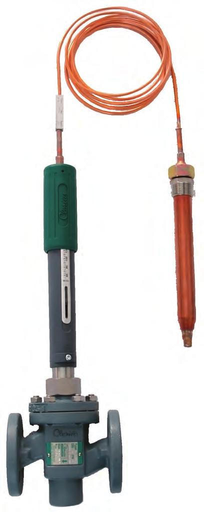
149 CLORIUSCONTROLS.COM SELF-ACTING TEMPERATURE CONTROLLER
150 CLORIUSCONTROLS.COM Why you should choose Self-acting temperature controller from Clorius Controls The thermostatic temperature controller, which consists of a thermostat and a valve, is used for controlling heating and cooling systems for central and district heating, industrial plants, marine, offshore, building and utility applications. Reliability Self-acting temperature controllers from Clorius Controls will operate in all conditions - without external controls or energy supply. This is why the temperature controllers will continuously adjust temperature even when energy supply has been interrupted and control systems have shut down. The reliability of the temperature controllers ensures continous operation instead of disasterous breakdown. 2
151 Precise Control Self-acting temperature controllers from Clorius Controls are available for controlling temperatures between -30 C and 280 C. The temperature controllers are easy to adjust and their technology makes it possible to maintain the set temperature very precisly, as the neutral zone of the controllers is from 1,5 C - 2,5 C. This ensures optimal operating conditions for the system being regulated. 2 Easy Maintenance It is easy to service self-acting temperature controllers from Clorius Controls. The simple mechanic construction can be disassembled and serviced even after years of operation by refilling liquid (glycerine) and mounting new seal rings in case of leakage. This means that controlling can continue without problems even when maintenance is required at remote destinations. A service instruction is included, and you will always have access to an online service instruction at www. cloriuscontrols.com 1 Maintenance During Operation It is not necessary to interrupt operations in order to service a self-acting temperature controlle from Clorius. The stuffing box is an independend unit, which can remain on the valve while the temperature controller is removed. This means that maintenance can be performed during normal operating hours without interrupting operations. A manual operating unit is available for use during building activities. 3
152 CLORIUSCONTROLS.COM How does it work? A thermostat consists of a sensor and a capillary tube filled with liquid and an adjusting cylinder. The thermostat is self-acting and based on the principle of liquid expansion; it has a sturdy design and operates with a large closing force. The adjusting cylinder of the thermostat is set at the required temperature for the heated medium in C. The temperature control is carried out by the thermostatically controlled valve reducing or increasing the flow of the heating (or cooling) medium. If the temperature of the medium to be heated is above the set point, the sensor liquid expands, causing the piston of the thermostat to act upon the valve, reducing the flow of the heating medium. If the temperature of the medium to be heated is below the required level, the temperature of the sensor liquid falls, reducing the volume of the liquid, so that the piston allows the valve to open under its internal spring, thus increasing the flow of the heated medium. 4


153 Rod sensor Valve Spiral sensor Temperature Sensor Spindle Packing Spiral sensor for air ducts Temperature Scale Protection Bellow O-Ring Piston Temperature Override Spring Sensor pocket Cylinder Cooling unit Adjusting Handle Capillary 3-21 m Liquid Filling Cooling unit with bellow Manual adjusting device 5
154 CLORIUSCONTROLS.COM Simple Construction Self-acting temperature controllers from Clorius Controls exploit the way in which liquid changes its volume as temperature fluctuates. Activation occures at deviations from the set temperature, where liquid from the sensor part influences the stem of the valve through a capillary tube. Thus there are no operating costs for controlling and activating the valve. Self-acting temperature controllers from Clorius Controls are also available with two sensors, which regulate according to the temperature at two measuring points. Individual Adjustment Self-acting temperature controllers from Clorius Controls come as a standard with 3 m capillary tube in copper, but are available with up to 21 m tube depending on the customer s need. The capillary tubes are available in copper or stainless steel and may also be protected by PVC or spiral reinforcement. Several types of sensors in copper and stainless acid-proof steel are available for different applications and measuring in different media. Threaded joints or flanges are available on request. For high-temperature use, cooling units for protection of the stuffing box are available. 6
 until the set temperature is the same as the actual temperature. The scale will now be accurate.")
155 Calibration The controller is easy to calibrate in case of discrepancies between the set temperature and the actual temperature. Move the scale (2) until the set temperature is the same as the actual temperature. The scale will now be accurate. Adjusting The Temperature Turn the handle (1) until the top of the scale bushing points to the wanted temperature on the scale (2). The temperature seating can be changed at any time, also while the controller is in use. Product Range When ordering a controller please specify the following: Controller type Temperature range Length of capillary tube Material of capillary tube Type of sensor Material of sensor Sensor connection Please refer to our data sheets for our selfacting temperature controllers - in order to find the correct specfications for your needs. Below you will find an overview of the main controller types: Thermostats Of Stainless Steel Clorius Controls additionally offers thermostats of stainless steel, which are particularly suitable for installation in demanding environments such as outdoor plants and in non-magnetic areas, e.g. in submarines. 2 1 Technical Data Controller Types V2.05 V4.03 V4.05 V4.10 V8.09 V8.18 Max. closing force N Setting range for standard thermostats 1) ºC Neutral zone ºC For valves with rated travel up to: Travel (amplification) in range: /ºC -30 to 160ºC 2) to 280ºC 3) ) Setting ranges from -30 to 280ºC on request. - Excess temp. safety range: 40ºC 2) Glycerine 3) Paraffin 7
156 CLORIUSCONTROLS.COM How you benefit... Good economy Flexibility Reliability Serviceability Good economy 1. Clorius thermostatic temperature controllers are self-acting and require no external power supply. This means no running costs and minimum installation costs. 2. Clorius thermostatic temperature controllers respond accurately and quickly to load changes due to their direct acting liquid system. Flexibility 3. Clorius thermostatic controllers can be delivered with different proportional bands fitting any control requirement. 4. Clorius thermostatic valves can be supplied from DN 15/4 up to DN way and 3-way valves are available in gun metal, cast iron, nodular cast iron or cast steel. 5. The valves can be supplied for working pressures up to PN 40 and maximum operating temperatures of 350 C, making them suitable for water, steam and hot oil systems. 6. The seat and cone design ensures a quadratic characteristic, providing excellent control at all loads. 7. Clorius thermostats can be supplied with three different closing forces: Type V2: 400 N Type V4: 500 N Type V8: 800 N 8. Clorius thermostats can be supplied with rod or spiral sensors with threaded or flanged connections. Sensors are made in copper or stainless steel. 9. Clorius thermostats are available with setting ranges between -30 C and 280 C. 10. Clorius thermostats can be supplied with capillary tubes in lengths up to 21 m in either copper, stainless steel or PVCcovered copper. 8
 compared with bellow systems. 13.")

157 Reliability 11. State-of-the-art mechanical technology and sturdy design ensure optimum reliability and accuracy, and give the thermostatic temperature controllers a long life. 12. Clorius direct acting thermostat systems have a very narrow neutral zone (1.5 C C) compared with bellow systems. 13. The use of a solid piston with a single O ring instead of bellows secures maximum actuator force and allows for complete onsite maintenance, if required. Self-acting temperature controllers are easily disassembled for maintenance purposes. 14. In case of excessive temperatures a built-in safety spring will compensate for any additional expansion in the thermostat s liquid system thereby preventing it from failure. One look at the controller will indicate whether the thermostat is exposed to excessive temperatures as the cylinder protrudes from the setting element. Serviceability 15. No special tools are required for servicing Clorius thermostatic temperature controllers. 16. The stuffing box is an integral part of the thermostatic element for easy and simple maintenance of the valve. 17. Clorius thermostats can be calibrated to ensure that scale values correspond to the value at the sensor. 18. Glycerine is available at local supermarkets etc. for refilling of the Clorius thermostat. In emergencies even water may be used. We refer to the instruction manual. Sensor liquid can be refilled in case of leakage. 19. An optional manual adjusting device is also available for continuous operation of the valve during installation, repair and maintenance of the Clorius thermostat. 20. Our customers can easily change the set point by turning the adjusting handle. 21. Clorius thermostatic temperature controllers can generally be repaired onsite, if required. 9
158 CLORIUSCONTROLS.COM Duostats Duostats are thermostats, type V, which via two sensing elements in a coon hydraulic system act on one and the same control valve. The sensing elements are two spiral sensors for the ventilation duct or two rod sensors (a combination of one spiral sensor and one rod sensor may be supplied in certain combinations). The effect, which the two sensing elements have on the adjustment, is proportional to the liquid volume of the individual sensors. Duostats are therefore available with varying proportions between the liquid volumes of the two sensors (sensor proportions) and in that way they can meet the requirements made by a number of different adjustment problems. As the adjustment result in a weighted average value of the temperatures of the two sensors, no fixed adjustment value can be indicated. Hence, Duostats are not equipped with a temperature scale, but with a marking for adjustment towards higher or lower temperatures, respectively. General applications Adjustment of discharge air temperatures in hot-air heating plants, dependant on the outdoor temperature. Adjustment of two temperatures which are interdependant. E.g. the hot-water tank of a district heating plant with simultaneous control that the return water temperature does not become to high. 10
159 General applications Air Heating Plants For air heating plants Duostats with two spiral sensing elements for air ducts are used. Fig. 1 shows an example of a plant with Duostat. The primary sensor V p is the real control sensor which goes into the controlled system. The secondary sensor V s which is located outside the controlled system, registers the outdoor temperature and determines the necessary air temperature by V p. If there is no supply air duct, where the secondary sensor can be built in, it can be placed in free air. For this purpose a wall bracket is available. Fig. 1 Other Applications Duostats are sometimes used for purposes where both sensing elements go into the same controlled system (see examples 2 and 3). The controlled condition will then be a weighted average of the registrations of the two sensors, as shown in the following examples. In fig. 2 a hot-water tank connected to district heating is adjusted by a Duostat whose one sensor - the primary sensor - controls the temperature of the tank which should be constant. The secondary sensor registers the temperature of the water which is led back to the district heating network. It secures that the valve does not open so much that the temperature of the return water rises in an uncontrolled manner, when a large water consumption reduces the temperature in the tank. Fig. 3 shows a room heated by hot air. The primary sensor is built into the extract air duct in order to serve as a room thermostat from this place. The secondary sensor is built into the discharge air duct where it counteracts that the discharge air temperature becomes too low - which would feel like a draught - when the room temperature rises as a result of the heat development which may come from persons or heating processes in the room. Fig. 2 Fig. 3 11
160 Kajakvej 4 DK-2770 Kastrup Denmark Tel.:
161
162


163 V2, V4 and V8 Thermostats Self-acting Temperature Controls K GB-1 Characteristics Closing force 400 N, 500 N and 800 N For heating or cooling valves Sturdy and reliable Temperature range 0 to 160ºC (-30 to 280ºC on request) Applications The temperature controller, which consists of a thermostat and a valve, is used for controlling the temperature in central heating systems, district heating systems, industrial plants or industrial processes and in marine systems. It can be used for the control of cold or hot water, steam or oil in heating as well as cooling systems. Function The adjusting cylinder of the thermostat is set at the required temperature for the heating medium in ºC. This setting can be fixed, if required. The temperature control is carried out by the thermostatically controlled valve reducing or increasing the flow of the heating (or cooling) medium. The sensor and the capillary tube, which are filled with a liquid, constitute - together with the adjusting cylinder - a closed system. If the temperature of a medium to be heated is above the required level, the temperature of the sensor liquid rises and expands, causing the piston of the thermostat to act upon the valve, reducing the flow of the heating medium. If the temperature of the medium to be heated is below the required level, the temperature of the sensor liquid falls, reducing the volume of the liquid, so that the piston allows the valve to open under its internal spring, thus increasing the flow of the heating medium. The neutral zone of a thermostat is the temperature difference which can occur at the sensor without any movement of the valve spindle. This represents the sensitivity of the control system to temperature changes: V2 = 2.5ºC, V4 = 2ºC and V8 = 1.5ºC. Design Thermostat A thermostat consists of a sensor and a capillary tube, filled with liquid, and an adjusting cylinder. The thermostat type designations and technical data are specified in fig. 2. With temperatures above 170ºC, a cooling unit must be fitted between the valve and the thermostat - see fig. 1. The thermostat is self-acting and works on the principle of liquid expansion, it is sturdy in its design, and works with a large closing force. Sensor The following sensor types are available - see fig. 4: 4.1. Rod sensor in copper or stainless steel and spiral sensor in copper with threaded connection according to ISO R7/ Spiral sensor (copper only) with air duct flange Rod/spiral sensor with steel flange DN 50, PN 40 and DN 50, PN Sensor without connection. Usually used with capillary pack box for temperature control in tanks. Capillary Tube The capillary tube is made of copper, stainless steel, or of PVC-coated copper - see fig. 3, but can also be delivered with a flexible iron tube protection. Valve A wide range of valve types for heating as well as cooling systems can be delivered. See the Quick Choice leaflet no and datasheets for the valves in question. Subject to changes, without notice.


164 V2, V4 and V8 Thermostats Self-acting Temperature Controls K GB-2 Choice of Temperature Control The selection of the correct temperature controller is determined by the sizing of the valve and thermostat respectively, which may be chosen by using the Quick Choice leaflet no The designation of the thermostat is determined by using 3 elements, e.g. thermostat type V4.05, where V indicates type V thermostat, 4 is Clorius production number, and 05 relates to the travel of the thermostat spindle in by a temperature change of 1ºC - see also fig. 2. Fig. 1. Temperature Limits Temperature of valve medium: -30ºC 170ºC 250ºC 350ºC Fig. 1 indicates whether the temperature of the heating medium necessitates a cooling unit, and how the thermostat is to be mounted in relation to the valve; for a temperature range -30ºC to 170ºC the thermostat may be installed both above and below the valve. Fig. 2 shows the type number of the thermostat, its closing force in N and its setting range in ºC. Fig. 3 shows the choices of length and material for the capillary tubes. Fig. 4 shows the different types of sensors. Fig. 5 shows the time coefficients for the sensors. Fig. 6 shows the choices of sensor materials, etc. Fig. 7 shows the dimensions and weights of the sensors etc. Mounted upwards or downwards Mounted only downwards Without cooling unit With cooling unit KS-4 1) With cooling unit KS-5 1) Temperature of sensor: -30ºC 140ºC 160ºC 280ºC Glycerin filled Sensor of copper 2) Sensor of stainless steel For marine installations please see instruction manual. Paraffin filled 1) See Accessories on page 4. 2) Max. 160ºC - incl. 40ºC overtemperature. Fig. 2. Thermostat Types Technical Data Thermostat Types V2.05 V4.03 V4.05 V4.10 V8.09 V8.18 Max. closing force N Setting range for standard thermostats 1) ºC Neutral zone ºC For valves with rated travel up to: Travel (amplification) in range: /ºC -30 to 160ºC 2) to 280ºC 3) ) Setting ranges from 30 to 280ºC on request. Excess temp. safety range: 40ºC 2) Glycerine 3) Paraffin Subject to changes, without notice.


165 V2, V4 and V8 Thermostats Self-acting Temperature Controls K GB-3 Rod Sensor Spiral Sensor Fig. 3. Capillary Tubes Choice of capillary tube, length and material, is determined according to the table below, independent of the choice of the thermostat type. Length Copper PVC-coated copper Stainless steel 3 m 4.5 m 6 m 7.5 m 9 m 10.5 m 12 m 13.5 m 15 m 16.5 m 18 m 19.5 m 21 m Capillary Tube Fig. 4. Sensor Types 1. Sensors with threaded connection 2. Sensors with air duct flange Adjusting Handle 3. Sensors with steel flange 4. Sensors without connection Available with capillary pack box Scale Adjustment Union Nut Subject to changes, without notice.


166 V2, V4 and V8 Thermostats Self-acting Temperature Controls K GB-4 Fig. 5. Time Coefficient for Sensors The time coefficients for rod and spiral sensors are measured in water flowing at a velocity of 1 m/sec., for air duct spiral sensors in air at a velocity of 4 m/sec. In the table the time lag T D and time coefficient T are indicated in sec. Type Rod sensor Copper Acid-resistant stainless steel Copper with sensor pocket Spiral sensor Spiral sensor for air duct Rod sensor Spiral sensor Rod sensor Liquid in sensor pocket T D T T D T T T D T T D T T D T V Hot oil V Hot oil V Hot oil V Hot oil V Hot oil V Fig. 6. Sensor Material etc. Adjusting cylinder Copper sensors Acid-resistant stainless steel sensors Capillary tubes Copper = c Stainless steel = n a b c d e f h k n DIN/EN no OM Metal Material no OM Metal Accessories Manual Adjusting Device Cooling Unit KS-4 Cooling Unit KS-5 With stuffing box. For tightening and manual operation of the valves, when an actuator has not been fitted, e.g. during periods of construction. Cooling unit protecting the stuffing box of the motor/thermostat. To be applied at valve temperatures between 170ºC and 250ºC. Cooling unit with built-in bellows gland. Replaces the stuffing box of thermostat. Must be applied by valve temperatures between 250ºC and 350ºC. Subject to changes, without notice.
167 V2, V4 and V8 Thermostats Self-acting Temperature Controls Fig. 7. Dimensions and Weights The measurements G and H are pipe threads according to ISO R7/1. All other measurements are. Weight: Net. c = Copper sensor. s = Acid resistant stainless steel sensor. Thermostat / Sensor material Type V2.05 Type V4.03 Type V4.05 Type V4.10 Type V8.09 Type V8.18 c s c s c s c s c s c s K GB-5 Dimensional Sketch Adjusting cylinder A B Weights: see below Sensor with threaded connection Weight incl. G connection Weight incl. H connection Sensors with air duct flange C D E F G R¾ R¾ R1 R1 R1 R1 R1 R1 R2 R2 R2 H R2 R2 R2 R2 R2 R2 R2 R2 R2 R2 R2 kg kg F I L M kg Sensor with steel flange DN 50, PN 40 Sensor with steel flange DN 50, PN 160 E F N O P 4x18 4x18 4x18 4x18 4x18 4x18 4x18 4x18 4x18 4x18 4x18 R S T kg E F N O P 4x27 4x27 4x27 4x27 4x27 4x27 4x27 4x27 4x27 4x27 4x27 R S T kg Sensors without connection Available with capillary pack box in stainless steel (1.4436) E F G R1 R1 R1 R1 R1 R1 R1 R1 R2 R2 R2 H R2 R2 R2 R2 R2 R2 R2 R2 R2 R2 R2 U V kg 1) kg 2) kg 3) kg 4) Subject to changes, without notice.
168


169 Thermostats of stainless steel types V4.03 and V E GB-1 Characteristics Self-acting P-controller Completely sealed Excess temperature protection All parts made of stainless steel Non-magnetic Application The thermostat is particularly suitable for installation in demanding environments such as tank installations, outdoor plants and where it must be non-magnetic, e.g. in submarines. Function The adjusting cylinder of the thermostat is set at the temperature in ºC for the required heated medium. The temperature is regulated by the thermostatically controlled valve reducing or increasing the flow of the heating medium. Together with the adjusting cylinder, the liquid-filled sensor and capillary tube constitute a closed system. If the temperature of the medium to be heated is above the required level, the sensor liquid expands, causing the spindle of the thermostat to act upon the valve, thereby reducing the flow of the heating medium. If the temperature is below the required level, the temperature of the liquid in the sensor decreases and the volume is reduced, thereby the valve spring opens the valve causing an increasing flow of the heating medium. Construction The parts of the thermostat are made of stainless steel. The thermostat consists of a liquid-filled sensor, a capillary tube, and an adjusting cylinder. The adjusting cylinder has O ring sealings and is sealed with silicone glue at the top for hermetical closure. The thermostat is available with settings between -30ºC and +280ºC. At flow temperatures above 170ºC, a cooling unit must be installed between the valve and the thermostat. Please see datasheet no Neutral Zone The neutral zone of the thermostat, which is less than 2ºC, is the temperature difference which can accur at the sensor without the thermostat spindle being actuated. Sensor types Rod or spiral sensors of stainless steel with pipe thread. Sensors are also available with a packbox on the capillary tube for applications where the sensor is to be lowered into a tank etc. Sensor liquid Glycerine at a scale range between - 30ºC and 160ºC. Paraffin at a scale range between 140ºC and 280ºC. Capillary tube The capillary tube is made of stainless steel and is available in lengths from 3 m up to 21 m. Valves The thermostat may be used for valves up to DN 150 for heating and cooling plants. See data sheet "Quick choice of temperature controller" no and data sheet for the particular valve. Technical data Max. closing force 500 N Standard settings: -Type V ºC -Type V , ºC Reinforcement (/ºC): (Glycerine) Type V4.03: 0.3 Type V4.05: 0.5 (Paraffin) Type V4.03: 0.33 Type V4.05: 0.7 For valves with lifting height up to 21 Sensor material W. No Time constant for rod sensor: - Type V4.03: 90 sec. - Type V4.05: 100 sec. Time constant for spiral sensor, sec. 20 Neutral zone < 2ºC Excess temperature protection 40ºC Subject to change without notice.
170 Thermostats of stainless steel types V4.03 and V E GB-2 Sensors with pipe thread Type V4.03 Type V4.05 C E G D F H C D E F G* H* " 2" " 2" Weight including G connection 2.4 kg 2.6 kg Weight including H connection 2.9 kg 3.1 kg Sensors without connection Available with capillary packbox Type V4.03 Type V4.05 1) 2) E E F U V 3) 4) G H Measurements in min F U V G* H* " 2" " 2" Weight * The measurements G and H are pipe threads according to ISO R7/1. 1) 2.2 kg 2.3 kg 2) 2.2 kg 2.4 kg 3) 2.4 kg 2.6 kg 4) 2.9 kg 3.1 kg Subject to change without notice.

.")
171 Duostats Self-acting Temperature Controls F GB-1 Clorius Duostats Duostats are thermostats, type V, which via two sensing elements in a coon hydraulic system act on one and the same control valve. Two basic types are available: V4.05 or V4.10, depending on the preferable proportional band PB, and the valve size. For more details, see the diagrams in the Quick Choice leaflet no The sensing elements are two spiral sensors for the ventilation duct or two rod sensors (a combination of one spiral sensor and one rod sensor may be supplied in certain combinations). The effect, which the two sensing elements have on the adjustment, is proportional to the liquid volume of the individual sensors. Duostats are therefore available with varying proportions between the liquid volumes of the two sensors (sensor proportions) and in that way they can meet the requirements made by a number of different adjustment problems. As the adjustment result is a weighted average value of the temperatures of the two sensors, no fixed adjustment value can be indicated. Hence, Duostats are not equipped with a temperature scale, but with a marking for adjustment towards higher or lower temperatures, respectively. Applications 1. Adjustment of discharge air temperatures in hot-air heating plants, dependent on the outdoor temperature. 2. Adjustment of two temperatures which are interdependent. E.g. the hot-water tank of a district heating plant with simultaneous control that the return water temperature does not become too high.
172 Duostats Self-acting Temperature Controls F GB-2 Selection of Duostat Type Duostats for room heating are supplied with seven different sensor combinations which cover all requirements seen in practice. On selecting the suitable Duostat, the diagram A is used in the following manner: When the correct basic type (V4.05 or V4.10) has been chosen from the combination diagram in the Quick Choice leaflet, look at diagram A for the max. discharge air/flow temperature (t i max ), for which the plant has been dimensioned by the outdoor temperature (t u min ). From here you follow the vertical lines to the crossing with the respective t u min curve. The intersection lies within the area of the suitable sensor combination, the technical data of which are shown on page 4. Example A 50 M1F valve combined with a V4.10 thermostat, chosen from the combination diagrams in the Quick Choice leaflet, has to regulate by t i max = 40 C and t u min = -15 C. The Duostat curve sheet gives the sensor proportion C, and the Duostat will be type V4.10 C, which has the sensor proportion 0.7:1. This value may be calculated from equation 2) and 3) on page 3: V s = 1.25 t i = = 0.7 V p t u If, for instance, a capillary tube of 6 m is required from the adjusting cylinder to the secondary sensor and 3 m to the primary sensor, you specify: Valve: Duostat: Capillary tube: Adjusting cylinder - secondary sensor Adjusting cylinder - primary sensor 50 M1F V4.10 C 6 m 3 m Applications Air Heating Plants For air heating plants Duostats with two spiral sensing elements for air ducts are used. Fig. 1 shows an example of a plant with Duostat. The primary sensor V p (red) is the real control sensor which goes into the controlled system. The secondary sensor V s (blue) which is located outside the controlled system, registers the outdoor temperature and determines the necessary air temperature by V p. If there is no supply air duct, where the secondary sensor can be built in, it can be placed in free air. For this purpose a wall bracket is available. In order to determine the correct Duostat, use diagram A where the combinations of spiral sensors for air ducts are found on the left hand. Other Applications Duostats are sometimes used for purposes where both sensing elements go into the same controlled system (see examples 2 and 3). The controlled condition will then be a weighted average of the registrations of the two sensors, as shown in the following examples. In fig. 2 a hot-water tank connected to district heating is adjusted by a Duostat whose one sensor - the primary sensor - controls the temperature of the tank which should be constant. The secondary sensor registers the temperature of the water which is led back to the district heating network. It secures that the valve does not open so much that the temperature of the return water rises in an uncontrolled manner, when a large water consumption reduces the temperature in the tank. Fig. 3 shows a room heated by hot air. The primary sensor is built into the extract air duct in order to serve as a room thermostat from this place. The secondary sensor is built into the discharge air duct where it counteracts that the discharge air temperature becomes too low - which would feel like a draught - when the room temperature rises as a result of the heat development which may come from persons or heating processes in the room. Fig. 2 Fig. 3
173 Duostats Self-acting Temperature Controls F GB-3 Theoretical Basis The theoretical basis for the use of Duostats for room heating plants rests on the balance between the heat brought to the plant, and the thermal loss from the heated rooms to the surroundings. By hot-air plants (fig. 1) this may approximately be expressed by equation 1), but with small changes, these consider ations may be applied to central heating plants with water as the heat carrier. 1) Lc p (t i - t u ) = Σ kf(t r - t u ) Here L is the quantity of air which is heated from the outdoor temperature t u to the discharge temperature t i, and c p is the specific heat of the air. k f expresses the sum of transmission surfaces, joints, etc., through which heat is lost to the surroundings by the difference between the temperatures of the heated rooms t r and the outdoor tempe rature t u. As L, c p, k f and the room tem perature are constant sizes, equation 1) can be converted into: 2) t i max - t i min = t i = n t u max - t u min t u Here t i max and t u min are belonging values for the calculated discharge air temperature by the outdoor temperature for which the plant has been dimensioned. In the same way, t i min and t u max are interbelonging values by the condition where the thermal loss is 0 (normally 20 C). The size n expresses how many degrees t i has to be raised, when t u falls one de gree. It is constant for the individual plant, but varies from plant to plant. This problem can be met by supplying the Duostats with different sensor propor tions. The proportion between the liquid volume in secondary and primary sen sors is: 3) VS = 1.25n V P This formula is approximate, as the ex pansion coefficient of the liquid (glycerine) varies with the temperature, which is compensated for with the factor 1.25.


174 Duostats Self-acting Temperature Controls F GB-4 Type V4.05 A V4.05 B V4.05 C V4.05 D V4.05 E Closing power N Length of secondary sensor L Secondary sensor s windings W S Secondary sensor s time constant * sec Primary sensors s time constant * sec Sensor proportion V S : V P 0.35:1 0.5:1 0.7:1 1:1 1.4:1 Excess temperature protector C Max. lifting height Travel / C Type V4.10 A V4.10 B V4.10 C V4.10 D V4.10 E Closing power N Length of secondary sensor L Secondary sensor s windings W S Secondary sensor s time constant * sec Primary sensors s time constant * sec Sensor proportion V S : V P 0.35:1 0.5:1 0.7:1 1:1 1.45:1 Excess temperature protector C Max. lifting height Travel / C Type V4.05 L V4.05 M Closing power N Length of secondary sensor C Secondary sensor s diam. E Secondary sensor s thread conn. G ISO 7/1 R 1 R 1 Secondary sensor s time constant * sec Primary sensor s time constant * sec Sensor proportion V S : V P 1:1 2:1 Excess temperature protector C Max. lifting height Travel / C Type V4.10 L V4.10 N Closing power N Length of secondary sensor C } Secondary sensor s diam. E Secondary sensor s thread conn. G ISO 7/1 R 1 R 2 Secondary sensor s time constant * sec Primary sensor s time constant * sec Sensor proportion V S : V P 1:1 2.9:1 Excess temperature protector C Max. lifting height Travel / C High alloy stainless steel * The time constants are for spiral sensing elements for air ducts measured in air with a velocity of 4 m/sec. For rod sensing elements they are measured in water with a velocity of 1 m/sec. Order diagram By specifications of Duostats, the following information is given: Example 1. Valve. Dimension and type 15 M1F 2. Duostat. Basic type and sensor proportion V4.05 C 3. Capillary tube from adjusting cylinder to secondary sensor (V s, blue) 6 m 4. Capillary tube from adjusting cylinder to primary sensor (V p, red) 3 m


175 Pressure Differential Controls Type TD J GB-1 Pressure differential controls, type TD, comprise a control valve, a diaphragm unit and 2 connecting capillaries. TDS Type TDS is supplied fitted to a brass valve and is available in four size/ range combinations. For further information, see separate data sheet no The large controls type TD56-2, TD66-4 and TD66-8 can be used with our wide range of 2-way control valves, in sizes from 4 up to 80 (type TD56-2M up to DN 150 ). For further information see Quick Choice no and data sheets for individual valves. TD56-2 is delivered complete with actuator and valve - please see datasheet and The diaphragm housings are made of cast iron and the diaphragms of synthetic rubber clamped between 2 steel discs. To prevent the diaphragm from being ruptured, a safety overload spring is fitted between the diaphragm and the valve to prevent damage when subjected to excess pressure, forcing the diaphragm against the housing. TD66 TD56-2 The controls are proportional controls. The proportional band is given as a percentage of set pressure value or as a pressure dependant upon the control type and the setting range. The TD-controls are primarily for use in water systems where they maintain a constant differential pressure across 2 points and ensure stable flow conditions. With the lower pressure connected to the valve side of the diaphragm and the higher pressure to the other side; the differential pressure across the diaphragm will be balanced by the force exerted by the spring. Any change in the differential pressure will cause the diaphragm and the valve mechanism to move up or down to restore the set condition. Working principle of the TD-Controls Fig. 1. In the control valve the pressure is reduced from P1 to P2, and the control keeps (P2-P3) constant at a set value, although the external pressures P1 and P3 or the resistance R may be fluctuating. Sizing of the valve is based on the smallest value of (P1-P2) with the maximum flow. For further information, see Quick Choice leaflet no Similarly, fig. 2 shows the TD-control installed after the resistance R (in the return flow). In this case, (P2-P3) forms the basis for sizing the valve. Applications District Heating - in Housing Circuits without by-passes The function of the TD-controls is to reduce the high and fluctuating pump head in the district heating system to a suitable and, under all circumstances, a constant differential pressure. It is very important that the TD-controls reduce the water flow as much as possible, to satisfy the design temperature drop across radiators and maintain heat output without excessive water flow. An inexpensive arrangement for a district heating scheme is to use the TD-control instead of a return by-pass to reduce the flow rate to a minimum. This results in small bore pipework and reduces the need for additional pumps or electrically operated controls. Subject to change without notice.
176 Pressure Differential Controls Type TD J GB-2 Depending on the circumstances, the TD-controls may be installed in the return main (fig. 3) or the flow main (fig. 4). Installation in the return main is preferable where there is a risk of air in the system, and in high buildings where the pressure in the return main does not considerably exceed the static head. For low buildings, and high flow pressures, it is normally preferable to install the TD in the flow main to reduce the pressure in the radiators to a level almost equivalent to the static head in the return main. Please also note the TD-control in the district heating circuit of the hot water tank (H.W.T), and that the capillaries are connected across the control valves, maintaining a constant differential pressure across the valves and an optimum control. The H.W.T s control valve should be as small as possible ensuring a slow heating and a good cooling of the district heating water. Pressure Stabilization for Temperature Control The TD-controls also apply for heating systems with heat exchangers see fig. 5. When temperatures have to be kept within close limits e.g. in ventilating plants, control may be difficult if the differential pressure in the system is not constant or is very high. This can be overcome by installing a TD-control in front of one or more places to be controlled. Examples are shown in fig. 6, and 7. Fig. 6 is for district heating, direct supply, whereas fig. 7 is for boiler supply. Note that a by-pass is established by a 3-way valve and a TD control. The TD-controls can be used with our range of reverse acting valves in by-pass around pumps or across the flow and return pipes of a circuit - see fig. 8 (boiler supply). This avoids the pump working against a dead head when all the sub-circuits are closed down and stops any bypassing on motorised valves or thermostatic radiator valves. Noise Prevention Noise from central heating installations can often be overcome by TD-controls. The noise arising from a control valve is normally related to the pressure drop across it. Experts recoend that the pressure drop across radiator valves should not exceed 80 mbar, especially in the case of living room applications. In blocks of buildings with a coon district heating station, there has, in recent years, been a tendency to increase the main pump head and this often results in valve noise. Fig. 9 shows an example of the circuit to a block of buildings. The TDcontrol on the take off from the distribution main reduces the high pump head to suit the local pump head. TD-controls in each individual circuit further reduce the differential pressure across the system to the above mentioned 80 mbar. The pressure differential across the TD-controls itself may exceed 2 bar if the distribution pump head is high. In such cases, to avoid noise problems, the TD-controls should be installed well away from living quarters and the iediate pipework should be well muffled. Subject to change without notice.


177 Pressure Differential Controls Type TDS E GB-1 Characteristics Small dimensions Good regulating accuracy Nominal pressure PN 16 Max. temperature 150 C Self-acting Low-noise control. (Tested according to ISO/DP 3822/1 - test results on request.) Applications The TDS controllers, which are made in four variants, have the following major applications: Control of differential pressure, noise and dynamic balance. In individual users circuits and sub-mains within a large distribution network. For example in District Heating or Group Heating networks. Control of by-pass between flow and return where 3-way valves or 2-way zone control valves are installed. To limit volume variations and maximum Δp. Similarly for low water content boilers and devices requiring a minimum circulation irrespective of load conditions. With the addition of a miniature solenoid valve in the impulse connection the valve can also be used to isolate a circuit with respect to time or temperature. Example of integration of TDS into an existing installation Function The TDS controller can be installed in either the flow or return of the sub-circuits. The high pressure line is connected to the adjustment side of the diaphragm housing and the low pressure line to the valve body side of the diaphragm. Any change of differential pressure across the diaphragm - which is connected to the valve mechanism - above or below the set point will cause the diaphragm to change its position. If higher than set pressure the valve will move to close, if lower than set pressure the valve will move to open, until the system is once again in balance. Adjustment of the differential pressure setting is made by rotating the adjusting handle clockwise or anticlockwise until the desired set point is reached (see diagram). The upper edge of the adjustment cap in conjunction with the scale marked on the spring guide tube is an indication of the actual setting. The scale moves into or out of the handle loading the valve and diaphragm. The set pressure is shown on a percentage scale in 10% increments. Relation between Scale Setting and Differential Pressure Differential pressure bar Design TDS 15-1/ TDS 15-5/ The TDS controller is a spring loaded selfacting proportional controller consisting of a valve, a diaphragm and housing and two capillary tubes on either side of the diaphragm. The valve body,available in DN15 and DN20, is made of hot-pressed brass, and the seat and cone of stainless steel. The diaphragm housing is made % Scale setting of nudular cast iron, and the diaphragm itself is made of EPDM rubber with web reinforcement. If required, the TDS controller adjustment handle can be sealed, preventing unauthorised persons from altering the set point. Subject to change, without notice.
178 Pressure Differential Controls Type TDS E GB-2 Installation According to the conditions, the TDS controller can be built into either the return pipe or the flow pipe in a suitable position and the small dimensions of the TDS controller make it easy to mount in most installations. The diaphragm area is still large enough to give a sensitive response to small pressure variations; it is designed to be a compact controller without sacrificing performance. Technical Data Materials: - Valve body Hot-pressed brass (W. no ASTM B283) - Seat and cone Stainless steel (W. no AISI 303) - Diaphragm housing Nudular cast iron EN-GJS (W. no ASTM A395) - Diaphragm EPDM rubber with web reinforcement (ASTM D2000) - Capillary Copper (ASTM B42) 2x1 m Type of valve Single seated Valve characteristic Linear (approx.) Weight, incl. valve 2.5 kg Pressure drop across valve Δp V bar Sizing Chart Valve: Type Setting range bar TDS TDS TDS TDS TDS Proportional band mbar Max. thrust on stem N Nom. pressure PN bar Max. rated travel 7 7 Max. temp. of liquid C 130 (150) 1) 130 (150) 1) Note Incl. hot pressed brass valve, Rp ½ k vs =1.5, Δp L =7 bar Incl. hot pressed brass valve, Rp ¾ k vs =2.4, Δp L =7 bar The max. pressure against which the controls can close Δp L, depends on the valves and it is stated above. To avoid noice problems it is recoended that the pressure drop across valve Δp V does not exceed 1 bar in living quarters. 1) 150 C - Only if TD cotroller is installed below the valve. k vs -value: 1.5 m 3 /h 2.4 m 3 /h 0.5 Subject to change, without notice Dimensions Flow l/h


179 Pressure Differential Controller Type TDL, PN 16, DN E GB-1 Characteristics Small dimensions Good regulating accuracy Nominal pressure PN 16 Max. temperature 150 C Self-acting Applications The TDL controllers which are made in 6 variants have the following major applications: Control of differential pressure, noise and dynamic balance. In individual users circuits and sub-mains within a large distribution network. For example in District Heating or Group Heating networks. Control of by-pass between flow and return where 3 port valves or 2 port zone control valves are instal led. To limit volume variations and maximum p. Similarly for low water content boilers and devices requiring a minimum circulation irrespective of load conditions. With the addition of a miniature solenoid valve in the impulse connection the valve can also be used to isolate a circuit with respect to time or temperature. Example of integration of TDL into an existing installation Function The TDL controller can be installed in either the flow or return of the sub-circuits. The high pressure line is connected to the adjustment side of the diapraghm housing and the low pressure line to the valve body side of the diapraghm. Any change of differential pressure across the diapraghm which is connected to the valve mechanism above or below the set point will cause the diapraghm to change its position. If higher than set pressure the valve will move to close, if lower than set pressure the valve will move to open, until the system is once again in balance. Adjustment of the differential pressure setting is made by rotating the adjusting handle clockwise or anticlockwise until the desired set point is reached (see diagram). The upper edge of the adjustment cap in conjunction with the scale marked on the spring guide tube is an indication of the actual setting. The scale moves into or out of the handle loading the valve and diapraghm. The set pressure is shown on a percentage scale in 10 % increments. Design The TDL controller is a self-acting proportional controller consisting of a valve, a diapraghm and housing and two capillary tubes on either side of the diapraghm. The valve body is made of gun metal, and the seat and cone of stainless steel. The diapraghm housing is made of nodular cast iron, and the diapraghm itself is made of EPDM rubber with web reinforcement. If required, the TDL controller adjustment handle can be sealed, preventing unauthorised persons from altering the set point. Installation According to the conditions, the TDL controller can be built into either the return pipe or the flow pipe in a suitable position and the small dimensions of the TDL controller make it easy to mount in most installations. The diapraghm area is still large enough to give a sensitive response to small pressure variations; it is designed to be a compact controller without sacrificing performance. Subject to change without notice.
180 Pressure Differential Controller Type TDL, PN 16, DN E GB-2 Technical Data Materials: Valve body Cone RG5 CuSn5Zn5Pb5-C Stainless steel (W.no AISI 303) Diapraghm housing Nodular cast iron EN-GJS (W.no ASTM A395) Diapraghm EPDM rubber with web reinforcement (ASTM D2000) Capillary 2 pieces of 1 m, Cu Pressure stage PN 16 Relation between scale setting and differential pressure Valve dimension 20-1/ / Differential pressure bar % Scale setting Dimension sketch Sizing chart bar 7 k vs -value: 20 L1SB 25 L1SB 32 L1SB m 3 /h H: DN 20 DN 25 DN m 3 /h Type designation TDL TDL TDL TDL TDL TDL Valve type 20 L1SB 20 L1SB 25 L1SB 25 L1SB 32 L1SB 32 L1SB Pressure stage PN 16 Max. temperature 150 C Max. diff. pressure, Δp, across the valve in bar Overall valve length in k vs -value Setting range in bar Proportional band 10% Weight in kg, incl. valve pcs capillary each 1 m enclosed, connection ISO 7 - R¼ Subject to change without notice.


181 Pressure Differential Controls Type TD D GB Pressure differential controls, type TD, comprise a control valve, a diaphragm unit and 2 connecting capillaries. The controls type TD66-4 and TD66-8 can be used with our wide range of 2-way control valves, in sizes from 4 up to 80. For further information see technical data, Quick Choice no and data sheets on individual valves. Type TD66 (TD66-4 and -8) is spring loaded and is available in several setting ranges. The differential pressure required is set by turning the handle, the upper edge of which acts as a pointer on the scale. Dimensions (If liquid temp. is below 120 C, TD-Controller may be installed on top of the valve) Technical Data Type TD66-4 TD66-8 Setting range bar Proportional band 10% 10% 30% 30% 20% Max. thrust on stem N Nom. pressure PN bar 16 1) 16 1) Max. rated travel Max. temp. of liquid C 120 (150) 2) 120 (150) 2) Weight kg 13 Note Primarily in connection with double seated valves up to DN 80 (Single seated valves only up to DN 25, and not balanced valves - type M1FB, G1FB, H1FB) 3) 1) PN is only valid for the diaphragm housing. See also data sheets for the valves. 2) 150 C - Only if TD controller is installed below the valve. 3) Balanced and larger single seated valves only to be selected if an increased variation of the desired diff. pressure p is allowable. (An increase of the inlet pressure may result in a substantial increase of p). Subject to change without notice.
182


183 Self-acting Differential Pressure Controls Type TD56-2G (PN 25) and TD56-2M (PN 16), DN F GB-1 Characteristics Exact regulating Nominal pressure PN 25 / PN 16 Self-acting Easy to install and use Applications This unit is designed for controlling of differential pressure in individual users circuits and sub-mains within a large distribution network. For instance in district heating or group heating networks. Control of by-pass between flow and return where 3 port valves or 2 port zone control valves are installed to limit volume variations and maximum p. Similarly for low water content boilers and devices requiring a minimum circulation irrespective of load conditions. Function The medium flows through the free area between the seat and cone in the direction indicated by the arrow on the body. The high pressure line is connected to the diaphragm housing via C1 and the low pressure line to the diaphragm housing via C2. Any change of differential pressure across the diaphragm which Bar Pressure/Temperature diagram TD56-2G is connected to the valve mechanism above or below the set point will cause the diaphragm to change its position. If higher than set pressure the valve will move to close, if lower than set pressure the valve will move to open, until the system is once again in balance. Adjustment of the differential pressure setting is made by rotating the setpoint adjuster clockwise or anticlockwise until the desired set point is reached. The valve cone is pressure balanced. The pressure acts onto the bottom and top surface of the cone at the same time. In this way, the forces produced by the media are compensated. Design The differential control valve is a selfacting unit consisting of a valve, springs, an actuator and two capillary tube connected on the upper and lower side of the actuator. The valve body is made of nodular cast iron. The seat and cone are made of stainless steel. The diaphragm is made of EPDM or NBR rubber, depending on the medium to be controlled. Quality assurance All valves are manufactured under an ISO 9001 certification and are pressure and leakage tested before shipment. For marine applications the valves can be supplied with relevant test certificates from recognized classification societies. C2 C1 Installation According to the conditions, the TD56-2 can be built into either the return pipe or the flow pipe in a suitable positions. The diaphragm area is large enough to give a sensitive response to small pressure variations C Bar TD56-2M On request On request C Specifications Type Flange connection DN in k vs -value m 3 /h Lifting height Weight kg 15 TD56-2G/M TD56-2G/M TD56-2G/M TD56-2G/M TD56-2G/M TD56-2G/M TD56-2G/M TD56-2G/M Set point bar Subject to change without notice.
184 Self-acting Differential Pressure Controls Type TD56-2G (PN 25) and TD56-2M (PN 16), DN F GB-2 Technical Data Materials: - TD56-2M valve body Nodular cast iron EN-GJS TD56-2G valve body Nodular cast iron EN-GJS Cone, Seat Stainless steel - O-ring A70H FEPM - Bolts, nuts 24 CrMo 4/A4 - Stag bolt, Set point adjuster St. 42, Electroplated - Spindle housing St. 42, Electroplated - Spring W. Nr powder coated - Diaphragm housing Steel Diaphragm NBR / EPDM Nominal pressure TD56-2G - 25 bar TD56-2M - 16 bar Seating Single-seated Valve characteristic Quadratic Leakage rate Temperature range 0.05% of k vs See pressure/ temperature diagram Flanges drilled according to: - TD56-2G EN PN 25 - TD56-2M EN PN 16 Counter flanges DIN 2634 Colour (valve body, cover): - TD56-2G Blue - TD56-2M Grey Dimension sketch Setpoint adjuster H1 H L d C2 k D b Definition of k vs -value The k vs -value is identical to the IEC flow coefficient k v and defined as the water flow rate in m 3 /h through the fully open valve by a constant differential pressure, p v, of 1 bar. Strainer It is recoended to use a strainer in front of the control valve if the liquid contains suspended particles. Subject to change without notice. Type L H1 H C b D (dia.) k (dia.) d dia. (number) 15 TD56-2G/M x (4) 20 TD56-2G/M x (4) 25 TD56-2G/M x (4) 32 TD56-2G/M x (4) 40 TD56-2G/M x (4) 50 TD56-2G/M x (4) 65 TD56-2G/M x (8) 80 TD56-2G/M x (8) C C1
185 Pressure Reducing Valves type G1PR (PN 25) and H1PR (PN 40), DN J GB-1 TECHNICAL DATA Fi l ng H1 Setpoint adjuster H From Pipe L d b k D Materials: H1PR valve body G1PR valve body Cone, Seat O-ring Bolts, nuts 24 CrMo 4/A4 Stag bolt, Set point adjuster Cast steel GP240GH (GS-C25) Nodular cast iron EN-GJS Stainless steel A70H FEPM St. 42, Electroplated Spindle housing St. 42, Electroplated Spring W. Nr powder coated Diaphragm housing Steel Diaphragm NBR / EPDM Nominal pressure PN 25 - G1PR PN 40 - H1PR Seating Single-seated Valve characteristic Quadratic Leakage rate 0.05% of k vs Temperature range See pressure/ temperature diagram Flanges drilled according to: H1PR EN PN 40 G1PR EN PN 25 Counter flanges DIN 2634 Colour (valve body, cover): H1PR G1PR Green Blue Compensation chamber 74.5 To actuator C SPECIFICATIONS Type L H1 H C b D (dia.) k (dia.) d dia. Flange connection k vs -value Lifting height (number) DN in m 3 /h kg 15 G/H1PR x (4) G/H1PR x (4) G/H1PR x (4) G/H1PR x (4) G/H1PR x (4) G/H1PR x (4) G/H1PR x (8) G/H1PR x (8) Weight SET POINT bar Maximum allowable differential pressure is 25 bar.
186 Pressure Reducing Valves type G1PR (PN 25) and H1PR (PN 40), DN J GB-2 CHARACTERISTICS Exact regulating Nominal pressure PN 25 / PN 40 Self-acting Easy to install and use APPLICATIONS This unit is designed for maintaining the pressure downstream of the valve to an adjusted set point value. DESIGN The pressure reducing valve is a self-acting unit consisting of a valve, springs, an actuator and one capillary tube connected on the upper side of the actuator. The valve body is made of nodular cast iron or cast steel. The seat and cone are made of stainless steel. The diaphragm is made of EPDM or NBR rubber, depending on the medium to be controlled. QUALITY ASSURANCE All valves are manufactured under an ISO 9001 certification and are pressure and leakage tested before shipment. For marine applications the valves can be supplied with relevant test certificates from recognized classification societies. FUNCTION The medium flows through the free area between the seat and cone in the direction indicated by the arrow on the body. The position of the valve cone determines the flow rate and consequently the pressure ratio across the valve. The downstream pressure is transmitted through the compensation chamber and the capillary to the diaphragm, where it is converted into a positioning force. This positioning force is adjusting the cone with dependence on the force of the operating springs. The spring force can be adjusted by using the setpoint adjuster. The valve cone is pressure balanced. The pressure acts onto the bottom and top surface of the cone at the same time. In this way, the forces produced by the media are compensated. PRESSURE/TEMPERATURE DIAGRAM INSTALLATION Bar G1PR The pressure reducing valve must be installed in a horizontal pipe with the actuator directed downwards. The flow through the valve must coincide with the arrow on the valve body On request STRAINER It is recoended to use a strainer in front of the control valve if the liquid contains suspended particles * C COMPENSATION CHAMBER Bar 40 H1PR For steam applications and media temperature above 100ºC a compensation chamber is needed On request * o C DEFINITION OF K VS -VALUE The k vs -value is identical to the IEC flow coefficient k v and defined as the water flow rate in m 3 /h through the fully open valve by a constant differential pressure, p v, of 1 bar. * For temperature above 100ºC a compensation chamber is needed. Subject to changes without notice.
187 Section 4 Electronic and electric controls
188
189 Microprocessor-based Controller type ER 2000 for Electronic Temperature Control G GB-1 Characteristics PI and PID performance Easy operation For heating and cooling systems in maritime and industrial installations Manual- / automatic changeover Robust self-optimization Alarm indicating a deviation from set point, positive or negative Only one sensor element Pt 100 required for control and temperature indication User-defined operation level 2- or 3-positional output for controlling the actuator Applications The ER 2000 controller is used for constant temperature control. It is suitable for all heating and cooling control systems. The controller is primarily intended for marine installations and other industrial applications - such as cooling water and lubricating oil installations, flow temperature control etc. Design The ER 2000 controller is designed for panel mounting. For easy start-up it has optimization for automatic determination of favourable control parameters. The optimization starts when changing the set point or when switching over from manual mode to automatic control. The optimization can be disregarded. For easy operation it has three keys - two for scrolling or changing values and an enter key. Two digital displays show the process variable and the set point. 3 LEDs indicate actuator opens, actuator closes and alarm. The controller can be switched from auto mode to manual mode. In manual mode the actuator can be opened, closed or stopped in a certain position. Three different alarm settings are possible: A: Alarm at a deviation from the set point SP B: Alarm at a fixed limit value C: Alarm at leaving a band around the set point SP. It can operate either as a three position or as a two position controller and has adjustable proportional band, integral action time and derivative action time. Function The temperature input comes via a Pt 100 sensor with a single sensing element. The measured value of the controlled variable is compared with the set point value and adjusted via a PI or a PID control structure. The ER 2000 can act as either a heating controller, the actuator closes at rising temperature, or as a cooling controller, the actuator opens at rising temperature. The ER 2000 permits direct reading of the actual temperature value (PV) and it is secured from failure in the measuring circuit, i.e. the controller can be set to give either a closing, an opening or remain in current position coand in case of sensor short circuit or sensor break. The error message Err appears in the LED display PV. Counication The controller is equipped with a RS 485 counication module. Technical Data Line voltage 230 V AC 115 V AC* } -15 % / +10 %, 50 / 60 Hz 24 V AC* *- optional (please specify) Power consumption Weight approx. 7 VA approx. 1 kg Permissible ambient temperature - Operation 0 to 50 C - Transport and storage -25 to + 65 C Degree of protection Front: IP 65 according to DIN Terminals: IP00 Design For control panel installation 96 x 96 x 135 (W x H x D) panel cut out 92 x 92 Installation position arbitrary Input Pt100, 0 C to 300 C Connection in three - wire system Option: 4-20 ma Output 2- or 3-point Option: 4-20 ma Measuring accuracy 0.1% of the measuring range Displays Two 4 - digit 7 segment displays, LED, red, character height = 13 Alarm Alarm type A, B, C; working contact normally closed circuit principle Relay Switching capacity: 250 V AC / 3 A Spark quenching element Data protection Semi - conductor memory Subject to changes without notice.
190 Microprocessor-based Controller type ER 2000 for Electronic Temperature Control G GB-2 Wiring diagram Microprocessor - based controller ER 2000 P N A B RS 485 P N PE 230V 50/60Hz 5 N 6 Electrical Connections - Optional external units ER N 6 ER N 6 P N ER N 6 MT90 M motor V motor MP Compressed air ER N 6 ER N 6 V motor No.1 MP Pneumatic valve normally closed CAR motor V motor No.2 MP Cooling: Remember to set controller into cooling mode. Dimensions in Panel cut out Subject to changes without notice.
191 Microprocessor-based Controller type ER 3000 for Electronic Temperature Control D GB-1 Characteristics PI-PID cascade controller Easy operation For cooling systems in maritime installations Manual- / automatic changeover Robust self-optimization Alarm indicating at deviation from set point, positive or negative User-defined operation level 2- or 3-positional output for controlling the actuator Applications The ER 3000 controller is used for constant temperature control. It is specially designed for large engine jacket cooling water systems where conventional single loop controllers cannot maintain a constant and precise temperature. Design The ER 3000 controller is designed for panel mounting. For easy start-up it has optimization for automatic determination of favourable control parameters. The optimization starts when changing the set point or when switching over from manual mode to automatic control. The optimization can be disregarded. For easy operation it has four keys - two for scrolling or changing values, an enter key and a key for choosing manual or automatic control. Two digital displays show the process variable and the set point. 7 LEDs indicate alarm, actuator opens, actuator closes, slave control, setpoint raising / lowering and manual mode. The controller can be switched from auto mode to manual mode. In manual mode the actuator can be opened, closed or stopped in a certain position. Three different alarm settings are possible: A: Alarm at a deviation from the set point SP B: Alarm at a fixed limit value C: Alarm at leaving a band around the set point SP The 3 alarm settings include alarm in case of sensor fault. It can operate either as a three position or as a two position controller and has adjustable proportional band, integral action time and derivative action time. Function The controller operates with two sensor inputs. One Pt 100 sensor is placed at the outlet from the engine and one Pt 100 sensor with a built-in 4-20 ma transmitter is placed at the inlet to the engine. The measured values of the controlled variables are compared with the set point value and adjusted via a PI or a PID control structure. When used for large engine jacket cooling water systems the controller must be set up as a cascade controller The cascade controller has two process variables - master and slave. The cascade controller compares the measured master value ( outlet from the engine ) with its setpoint and adjusts the setpoint of the slave variable ( inlet to the engine ) if neccesary. Technical Data Line voltage 230 V AC 115 V AC* -15 % / +10 %, 50 / 60 Hz } 24 V AC* *- optional (please specify) Power consumption Weight approx. 7 VA approx. 1 kg Permissible ambient temperature - Operation 0 to 50ºC - Transport and storage -25 to + 65ºC Degree of protection Front IP 65 according to DIN Terminals: IP00 Design For control panel installation 96 x 96 x 135 (W x H x D) panel cut out 92 x 92 Installation position arbitrary DI - feed voltage and measuring transducer feed voltage 24 V DC, Imax. = 60 ma Analog inputs Pt100, 2.4 = 0 C to 300 C or 2.2 = 0 C to 400 C or 2.50 = -50 C to 250 C Connection in three - wire system 0/4 to 20 ma, input resistance = 50 Ohm 0/2 to 10 V, input resistance = 100 KOhm Measuring accuracy 0.1% of the measuring range Digital inputs high active, Ri = 1 k W; 0V DC = low 15 V to 24 V DC = high Analog output for process variable 0 to +10 V corresponds with 0 to 300 C (2.4) or 0 to 400 C (2.2) or -50 C to 250 C (2,50), I max. = 2 ma Displays Two 4 - digit 7 segment displays, LED, red, character height = 13 Alarms Alarm type A, B, C; working contact normally closed circuit principle Relay Switching capacity: 250 V AC / 3 A Spark quenching element Data protection Semi - conductor memory Subject to changes without notice.
192 Microprocessor-based Controller type ER 3000 for Electronic Temperature Control D GB-2 Wiring diagram Microprocessor - based controller ER V 50/60Hz Electrical Connections - Optional external units ER N 6 ER 3000 ER N 6 P 5 N 6 N MT90 M motor V motor MP Compressed air ER N 6 Pneumatic valve normally closed CAR motor Cooling: Remember to set controller into cooling mode. Dimensions in Panel cut out Subject to changes without notice.

193 Microprocessor-based controller type ER 2000-P for electronic pressure control D GB-1 Characteristics PI and PID performance Easy operation For heating, cooling and pressure systems in maritime and industrial installations Manual- / automatic changeover Robust self-optimization Alarm indicating a deviation from set point, positive or negative User-defined operation level 2- or 3-point output for controlling the actuator Applications The ER 2000-P controller is used for constant pressure control. It is suitable for all heating and cooling control systems. The controller is primarily intended for marine installations and other industrial applications. Design The ER 2000-P controller is designed for panel mounting. For easy start-up it has optimization for automatic determination of favourable control parameters. The optimization starts when changing the set point or when switching over from manual mode to automatic control. The optimization can be disregarded. For easy operation it has three keys - two for scrolling or changing values and an enter key. Two digital displays show the process variable and the set point. 3 LEDs indicate actuator opens, actuator closes and alarm. The controller can be switched from auto mode to manual mode. In manual mode the actuator can be opened, closed or stopped in a certain position. Three different alarm settings are possible: A: Alarm at a deviation from the set point SP B: Alarm at a fixed limit value C: Alarm at leaving a band around the set point SP. It can operate either as a three position or as a two position controller and has adjustable proportional band, integral action time and derivative action time. Function The pressure input comes via a 4-20 ma signal. The measured value of the controlled variable is compared with the set point value and adjusted via a PI or a PID control structure. The ER 2000-P permits direct reading of the actual temperature value (PV) and it is secured from failure in the measuring circuit, i.e. the controller can be set to give either a closing, an opening or remain in current position coand in case of sensor short circuit or sensor break. The error message Err appears in the LED display PV. Counication The controller is equipped with a RS 485 counication module. Technical Data Line voltage 230 V AC 115 V AC* } -15 % / +10 %, 50 / 60 Hz 24 V AC* *- optional (please specify) Power consumption Weight approx. 7 VA approx. 1 kg Permissible ambient temperature - Operation 0 to 50 C - Transport and storage -25 to + 65 C Degree of protection Front: IP 65 according to DIN Terminals: IP00 Design For control panel installation 96 x 96 x 135 (W x H x D) panel cut out 92 x 92 Installation position Inputs Outputs Option: arbitrary 4-20 ma Measuring accuracy 0.1% of the measuring range 2- or 3-point 4-20 ma Displays Two 4 - digit 7 segment displays, LED, red, character height = 13 Alarm Alarm type A, B, C; working contact normally closed circuit principle Relay Switching capacity: 250 V AC / 3 A Spark quenching element Data protection Semi - conductor memory Subject to changes without notice.
194 Microprocessor-based controller type ER 2000-P for electronic pressure control D GB-2 Wiring diagram Microprocessor-based controller ER 2000 Pressure 24 or 230 V AC 50 Hz _ + 24 VDC externall supply Electrical Connections - Optional external units ER N 6 ER N 6 P N ER N 6 MT90 M motor V motor MP Compressed air ER N 6 ER N 6 Pneumatic valve normally closed V motor No.1 MP CAR motor V motor No.2 MP Cooling: Remember to set controller into cooling mode. Dimensions in Panel cut out Subject to changes without notice.

195 Temperature sensors type FF 12, FF 15 and G FF12-2 / 4-20mA for electronic temperature regulation Characteristics Resistance sensor Pt 100 Ω/0 C. Standardized design according to DIN Robust and reliable sensor for use in gaseous and liquid media, e.g. air, steam, gas, water or oil. For medium temperature up to 400 C. For pressures up to 50 bar. Internationally recognized for marine purposes To be used together with ER regulators. See data sheet no and GB-1 Applications The temperature sensors are used for registration of temperatures in tubes, tanks and ducts. The output signal of the sensor is used as reference for our ER regulators. Type FF 12-2 / 4-20 ma is equipped with a built-in 2-wire transmitter with 4-20 ma output signals. The sensor is used in conjunction with controller type ER 3000 (see datasheet ). Due to small installation dimensions and internationally widespread measuring element the sensor is especially fitted for marine purposes, just as the applications on land are innumerable. Bar Water Air Hot steam Design The sensor consists of a pocket, a connection head and a measuring insert. The pocket is constructed of acid proof steel and can stand temperature/pressure as stated in the diagram. The connection head is made of lightalloy metal and complies with IP 65. The measuring insert contains one or two measuring windings and may be fixed or exchangeable. The supply lines of the measuring insert are insulated from each other and from the insert tube Standard types with a ceramic insulator. Exchangeable measuring insert is mounted in the connection head by means of two spring loaded screws. This means that the measuring insert is always pressed towards the bottom of the pocket, and vibrations from the surroundings will not be transferred to the measuring insert, just like different heat evolutions of pocket and measuring insert are adjusted. Our standard types are shown in the below diagram. Type Measuring Coents FF 12-2 With exchangeable measuring insert 1 x Pt 100 FF 12-R Measuring insert for FF 12-2 FF 15-2 With exchangeable measuring insert 2 x Pt 100 FF 15-R Measuring insert for FF 15-2 FF 12-2 / 4-20 ma 4-20 ma With exchangeable measuring insert , , ºC Subject to change, without notice
196 Temperature sensors type FF 12, FF 15 and G FF12-2 / 4-20mA for electronic temperature regulation GB-2 Dimension sketch - type FF12-2 () 200 1) Ø 11 G½B M20x ) Alternative lengths are available on request: 100, 150, 200, 250 Data for Pockets According to DIN Material X10CrNiMoTi1810 W. No corresponding to AISI 316 Ti Connection: G½B. Permissible torque moment: 50 Nm. Permissible flow velocities: Air: 25 m/s Hot steam: 25 m/s Water: 3 m/s Reaction times at liquid velocity: 0.2 m/sec: t 1/2: 17s t 9/10: 44s t = total temperature step Max. pressure: 50 bar Max. temperature: 400 C Weight incl. insert: 1 kg Data for Measuring Insert According to DIN The basic value of the measuring resistance corresponds to DIN Measuring range: -50 C to C Measuring resistance: 1 x Pt 100 Ω or 2 x Pt 100 Ω Max. temperature: 400 C. Insulation resistance between measuring resistance and insert tube is over 1000 MΩ at room temperature. The insert is made of stainless steel. Spring travel: 8 Two-core coupling Resistance of inner cables for supply and return line of the measuring insert: 0.07 Ω/m Weight of loose insert: 0.06 kg Data for Connection Head According to DIN 43729, form B Material: Light-alloy metal Seal: IP 65 Ambient temperature: max. 200 C Examples of mounting Subject to change, without notice.


197 Electric Valve Actuator type VB and VBA for rated voltages of 24 V AC/DC or 230 V AC I GB-1 Characteristics 3-point controlled or analogue actuator Low built-in height Automatic meshing Automatic end stops Low noise Protection IP54 Manual operation possible Reversible function Application The electric actuator has been designed for fitting on Clorius valves with lifting heights up to 10. See datasheets for valves. The electric actuator is suitable for heating, cooling, ventilation, industrial systems, and such like. The electric actuator is available either as a 3-point controlled actuator or an analogue actuator, e.g. for BMS systems. Design The actuator has a 10 travel. The electric actuator has built-in automatic end stops to safeguard against overload. The gears are made of steel and synthetic materials and are greased for life thus requiring no maintenance. The actuator has a release mechanism allowing manual opening and closing of the valve. The actuator bracket is made of cast aluminium and all internal bearings are greased for life. The actuator bracket has a standard Clorius stuffing box with a PTFE gasket. The actuator housing is cast in bay blend plastic. The 3-point actuator is available for rated voltages of 24 V AC/DC or 230 V AC. Analogue actuators are available only in 24 V AC/DC. The actuator may be furnished with 2 auxiliary switches, freely adjustable. These switches are normally used to indicate valve fully open or valve fully closed. Function The electric actuator has automatic end stops, but the lifting height of the electric actuator has to be adjusted to the valve. If manual operation is required, activate the gear release button to operate the valve manually. When the gear release button is de-activated, the valve returns to automatic function. If permanent disengagement is required, cut-off the voltage and set the valve in the desired position. When connecting the current or after activation of the gear release button, the VBA actuator performs a self-test. The actuator will travel to both end stops. Actuators with accessories Voltage 230 V AC Control signal 3-point Number of auxiliary switches Travel VB V 2 VB V 0 VB V VB A Power supply (24 V or 230 V AC) 24 V AC/DC 3-point 2 VB V Number of auxiliary switches (0 or 2) Max. lifting height 10 Control signal (A - analog) Type 24 V AC/DC 50/60 Hz 0(2)-10 V DC 4-20 ma 0 VBA V 2 VBA V Subject to change without notice.
198 Electric Valve Actuator type VB and VBA for rated voltages of 24 V AC/DC or 230 V AC I GB-2 Technical Data Electrical data Nominal voltage Type VBA- -24 Type VB- -24 Type VB V AC, 50/60 Hz 24 V DC V AC, 50/60 Hz Nominal voltage range V AC/DC V AC Power consumption In operation 2 W at nominal torque 1.5 W at nominal torque 2.5 W at nominal torque At rest 0.4 W 0.2 W 0.6 W For wire sizing 4 VA 6 VA Connection Cable 3 m, 4 x Cable 3 m, 3 x Functional data Safety Torque (nominal torque) Force at valve spindle Control Control signal Y 0-10 V DC, typical input impedance 100 kω Min.10 Nm at nominal voltage 1200 N Working range 2-10 V DC - Position feedback (Measuring voltage) 2-10 V DC, max.1 ma - Position accuracy ±5% - Direction of rotation Reversible with switch 0 /1 Reversible with switch 0 or 1 Direction of rotation at Y = 0 V at switch position 0 resp.1 - Manual override Angle of rotation Running time Sound power level Position indication Gearing latch disengaged with pushbutton, to reset push again Max. 95, limited on both sides by means of adjustable, mechanical end stops 150 s Max. 35 db (A) Mechanical, pluggable Protection class III Safety extra-low voltage II Totally insulated Degree of protection EMC IP54 in any mounting position CE according to 89/336/EEC Low voltage directive - CE according to 73/23/EEC Mode of operation Type 1 (to EN ) Ambient temperature range C Non-operating temperature C Ambient humidity range 95%r.H., non-condensating (EN ) Maintenance Dimensions / Weight Dimensions Weight Maintenance-free See "Dimensions" 2,4 kg - For details regarding sufficient closing pressure ( p L ) for the valve preferred, see Quick Choice, leaflet no Subject to change without notice.
199 Electric Valve Actuator type VB and VBA for rated voltages of 24 V AC/DC or 230 V AC I GB-3 Wiring diagrams 24 V AC / 24 V DC Analogue 24 V AC / 24 V DC Open-close control V AC! Open-close control T ~ V Y U V V - } } Input Output VB- -24 VB VBA V AC/DC Analogue 4-20 ma Controller 24 V AC / 24 V DC 3-point control V AC! 3-point control 500 Ω DC V Socket 4-20 ma VB- -24 VB VBA- -24 Direction of rotation Dimensions () Safety notes! The electric actuator is not allowed to be used outside the specified field of application, especially not in aircraft or any other form of air transport. Assembly must be carried out by trained personnel. Any legal regulations or regulations issued by authorities must be observed during assembly. The device may only be opened at the manufacturer s site. It does not contain any parts that can be replaced or repaired by the user. The cable must not be removed from the device. The device contains electrical and electronic components and is not allowed to be disposed of as household refuse. All locally valid regulations and requirements must be observed. Caution: Power supply voltage! (VB- -230) Subject to change without notice.


200 Electric Valve Actuator type VB and VBA for rated voltages of 24 V AC/DC or 230 V AC I GB-4 Auxiliary switches S2A/300 Auxiliary switches, suitable for all electric actuators type VB/VBA. Application S2A auxiliary switches are used to signal positions or to execute switching functions in any angular position. Mode of operation A form-fit engagement is created between a driver disc and the clamp, causing the position to be directly transferred to the trip cams of the microswitches. The switching points can be freely selected within the specified range of rotation by means of a dial. The current switch position can be read at any time. Mounting The auxiliary switches are attached directly to the clamp of the electric actuator. The guiding grooves between the housing and the switch ensure a tightly sealing fit. Technical data No. of switches 2 x SPDT Switching capacity 1 ma...3 (0.5)A, 250 V AC Switching point Adjustable over the full range of rotation of the electric actuator (0...1). Can be preset by means of the scale. Connection Cable 3 m, 6 x Protection class II Totally insulated Degree of protection IP54 LV Directive CE according to 73/23/EEC Mode of operation Type 1.B (to EN ) Ambient temperature range C Non-operating temperature C Ambient humidity range 95%r.H., non-condensating (EN ) Maintenance Maintenance-free Dimensions 101 x 76 x 27 (L x W x H) Weight Approx.170 g Wiring diagram Dimensions () B E A B C E A C Safety notes The auxiliary switches are not allowed to be used outside the specified field of application, especially in aircraft or in any other airborne means of transport. Assembly must be carried out by trained personnel. Any legal regulations or regulations issued by authorities must be observed during assembly. The device may only be opened at the manufacturer s site. It does not contain any parts that can be replaced or repaired by the user. The cable must not be removed from the device.! The device contains electrical and electronic components and is not allowed to be disposed of as household refuse. All locally valid regulations and requirements must be observed. Subject to change without notice.

201 Valve Motor type V L 24 V AC or 230 V AC GB-1 Characteristics Small outer dimensions Large closing force Easy to fit and adjust Casing IP 44 Lifetime lubricated gearbox Comprehensive additional accessories incl. spring return Application The valve motor has been developed for activation of all Clorius types of valves in sizes up to DN 150. The valve motor can be used for heating, cooling, ventilation and industrial systems where the medium is water, steam or oil. The valve motor can be supplied for voltages of 24 V AC and 230 V AC. 24 V motors are available in two speeds see type diagram. The valve motor can be supplied with spring return for releasing at power failure, positional potentiometer and auxiliary switches. The valve motor can be mounted in all positions, but mounting above the valve is recoended. The stuffing box contains no copper combinations, i.e. the motor can be used in oil regulating systems without any risk of oil cracking. Dimensioning For sizing of control valve motors, please see "Quick Choice" leaflet no Design The valve motor is driven by a motor with gearing. The motor is monophase and synchronous with condenser start. The gearing is fitted in a closed gearbox of pressure die-cast aluminium, where all gear wheels and bearings are lifetime lubricated. All electric components, terminals and the cam discs of the switch functions are located for easy accessibility under a cover of self-extinguishing plastic. The stroke of the motor can through a crank mechanism with a scale be adjusted continuously, between 4 and 20 and thus be adapted to the lifting height of the valve in question. The crank mechanism has a pawl mechanism which by means of the operating lever releases the motor and the gearing so that the valve can be activated manually. The operation lever can be locked in various positions corresponding to the required valve flow. The valve motor is supplied with a stuffing box with a teflon gasket. The stuffing box is exchangeable as one unit. A safety spring between the stuffing box and the crank mechanism secures against overload. The valve motor can be supplied with spring return which is released in case of power failure and which fully opens respectively closes the valve. The closing spring is encased in a cylindrical housing. When the motor is fitted with spring return, the closing capacity is reduced by lifting heights >9. See figures in parenthesis in "Quick Choice" leaflet no Function The el-motor with gearing gives a 90 turning of the shaft. By means of the crank mechanism this turning is converted into an upward and downward motion adjustable between 4 and 20. The operating lever releases the el-motor and the gearing, and thereby the valve can be activated manually. The outer positions of the lever are marked with valve symbols on the toothed sector and on the front of the plastic cover. If the valve motor is fitted with a spring return this is mounted to close the valve in case of power failure. When removing the screw fixing the spring housing and turning the latter 180, the spring fully opens the valve in case of power failure. The spring is always compressed, and in permanent connection with the throughgoing shaft, ready for release. Engaging and dis-engaging takes place electromagnetically with a spring mechanism, which dis-engages an idle wheel in the gear-box in the event of power failure. As soon as the power is back the magnet re-engages the gear wheel, and the motor iediately seeks towards the position required from the controller. Type Designation Power 24 V AC - 50/60 Hz 24 V AC - 50/60 Hz 230 V AC - 50/60 Hz Speed 106 sec./ sec./ sec./90 Springreturn Without With Without Without With Without Positional potentiometer With Positional potentiometer No. of aux. switches No. of aux. switches 0 V1A V1C V 1E V1I V1K 1 V2A V2C V2E V2I V2K 2 V3A V3C V3E V3I V3K 0 V4A V4C V4E V4I V4K 1 V5A V5C V5E V5I V5K 2 V 6A V6C V6E V6I V6K Subject to changes without notice.
202 Valve Motor type V 24 V AC or 230 V AC L GB-2 Technical Data Power 24 V AC or 230 V AC +10/ 15%, 50/60 Hz Consumption 4 VA without spring return 9 VA with spring return Casing IP 44 Cable threading 1 PG PG 13.5 blind plug Speed 24 V: 106 or 212 sec. 230 V: 106 sec. Ambient temperature 15 C to +60 C Closing force 1200 N min. 500 N with spring return Stroke 4-20 Valve connection pipe threads G1 union nut Weight complete 2.7 kg without spring return 3.7 kg with spring return Dimension sketch Additional Equipment Positional potentiometer Number: 1 Resistance change at 90 motor turning: Ohm Auxiliary switches Number: 1 or 2 Function: change-over Power: max. 250 V AC Current: max. 10 A Spring return Closes (or opens) the valve in case of power failure Diagrams End switches 1 End switches 2 Motor Magnet for springreturn Auxiliary switch Mp Standard motor Extra equipment Positional potentiometer Subject to changes without notice.


203 Valve motor type AV Controlled by Analogue I/O signals D GB-1 Characteristics Compatible with BMS I/O Electronic control of end stop function Dead zone ensures steady control Available options: - voltage or current for I/O signals - separate supply of electronics - power supply for transmitter, if required - control speed 106 or 212 s/90 - spring-return, reversible Applications Analogue motor type AV is based on the 24 V valve motor type V concept, but it is equipped with an electronic motor control, which also controls the end stop function making end switches un necessary. The motor control makes it possible to operate within a BMS (Building Management System) with analogue in- and output terminals. See also data sheet for V motors no Dimensioning For sizing of control valve motors, please see "Quick Choice" leaflet no Design The motor itself is for 24 V AC, reversible monophased and synchronous with condenser start. The gearing is fitted in a closed gearbox of pressure die-cast aluminium. All gear wheels and bearings are lifetime lubricated, and all electric components located under a cover of self extinguishing plastic. The motor can be supplied with spring return which is released on loss of power, or an impulse from the fuse unit. The spring is encased in a cylindrical housing on the main shaft and will open or close fully, depending on the position of the housing on the shaft. When the motor is fitted with spring return, the torque/closing force is reduced in some cases see "Quick Choice" leaflet no Engaging and dis-engaging take place electromagnetically with a spring mechanism, which dis-engages an idle wheel in the gearbox on loss of power. As soon as the power is restored the magnet reengages the gear wheel and the motor moves towards the position required by the controller. Type AV mechanism The stroke of the valve motor is produced by a crank mechanism converting the turning angle to a linear movement. This can be adjusted between 4 and 20 to suit the rated travel of the valve. The crank has a pawl mechanism which can be activated by the operating lever, which releases the motor and the gearing so that the valve can be operated ma nually. The operation lever can be locked in various positions corresponding to the required flow rate. The valve motor is fitted with a stuff ing box with a teflon gasket but without copper combinations, to avoid the risk of oil cracking. The stuff ing box is exchangeable as one unit. A safety spring between the stuffing box and the crank mechanism secures against overload. Function The control electronics compare an analogue control signal from a BMS system or controller with an internal reference value generated by a potentiometer, sensing the position of the motor shaft. If the control signal is not in accordance with the internal reference value, the motor runs forwards or backwards, until balance has been restored. A built-in dead zone of ±4% of the total control range is incorporated. As long as the input variations do not exceed these limits, the motor will be stationary. For indication of the position, an analogue output terminal generates a signal corresponding to the position of the motor shaft. When the motor has reached the position required by the input signal, the analogue in- and outputs are in balance influenced by the dead zone. The control electronics are usually powered via the motor voltage 24 V AC, but as an option the electronics and the motor can be supplied separately to obtain galvanic separation. Where required a power supply to an external 4-20 ma transmitter, via a short circuit safe output terminal for 16 V / 20 ma is provided. When the valve motor is delivered from the factory, it is set at 0-10 V control- and output signals. By moving some jumpers, the signals can be changed into 2-10 V, 0-20 ma or 4-20 ma. Example: If an input of 2-10 V is chosen, the motor will run to closed position when the input is 2 V. If the input is increased to 10 V, the motor will run to fully open position and an input of 6 V will place the motor in the middle. The electronic control of the end stop function is disconnecting the motor via the positional potentiometer protecting the motor and gears against overload if input should exceed the limits an input below 2 V or above 10 V in the example above. Subject to changes, without notice. Key table Motor type AVA AVC AVE Product no Spring return Without With Without Control speed 106 sec./ sec./90
204 Valve motor type AV Controlled by Analogue I/O signals D GB-2 Technical Data Power supply 24 V AC +10% -15%, 50/60 Hz, 7 VA (12 VA with spring return) Analogue input Voltage in Closed position 0 V / 2 V Open position 10 V Dead zone ± 40 mv Input resistance approx. 100 kω Max. input voltage 40 V Dimensions Current in Closed position Open position Dead zone Input resistance Max. values Analogue output Voltage out Closed position Open position Output resistance 0 ma / 4 ma 20 ma ± 0.08 ma 250 Ω 40 ma, 10 V 0 V / 2 V 10 V 500 Ω G1 Current out Closed position 0 ma / 4 ma Open position 20 ma Load resistance max. 500 Ω Output for power supply Short-circuit-safe, for transmitter if any Voltage 16 V ±2 V Current min. 20 ma, max. 30 ma Output resistance approx. 100 Ω Alternative supply of electronics Either 24 V DC +20% -10% max. 100 ma Or 24 V AC +10% -15% max. 3 VA Other coon data Casing IP44 Control speed 106 or 212 s/90 Closing (Open) speed by spring return few sec. Ambient temperature -15 to 60 C Valve motor type AV Closing force 1200 N 1) Stroke 4 20 (adjustable) Installation Vertical up- and downwards Weight 2.7 kg (3.7 kg with spring return) Optional extras type AV Spring return closes or opens the valve on loss of power Time relay protects gear wheels where short-lived loss of power (< 5 s) can occur 1) With spring return the closing or opening capability is reduced in certain cases. Please see "Quick Choice" leaflet no Subject to changes, without notice.


205 Valve motor type MT90 Marine For valves DN F GB-1 Characteristics Motor for Clorius valves types L2FM, M2FM, G2FM, L3FM, M3FM and G3FM. MT90 is approved for marine applications by Germanischer Loyd, No HH Can be manually operated in case of power failure. Low or high voltage operation Digital or analogue version. Service No special service is necessary. It is recoended to check and grease the valve motor at every docking or every three year. Valve opening The valve opening can be seen on one of the stays. Application Valve motor type MT Marine is specially designed to meet the demands of the powerful low frequency vibration environments in marine installations. The main applications are cooling of freshwater - sea water - and oil-systems for main and auxiliary engines. Mounting For mounting and starting up, the instructions delivered with the motor must be followed carefully. The wiring diagram is fixed inside the motor cover. Valve and motor must be mounted with vertical stems. Free height above/below the motor has to be at least 175 for service. MT90 Control type: : Digital A: Analogue Valve size (): Supply voltage: 24 V 230 V Positional potentiometer (option) The positional potentiometer is ad justed to a 45 valve stroke. If using valves with a stroke less than 45, the signal will be reduced according to the table below. Valve size DN Resistance range in % % 300/ % % % % % %. Positional potentiometer in kω No. of auxiliary switches: 0 2 Technical data Power supply 24 V AC, 50/60 Hz or 230 V, 50/60 Hz Consumption 6.7 W Closing force 1200 N Spindle speed 25 /min. Casing IP65 Ambient temp. -20 to +60 C Humidity 0-100% R.H Manual operation included Weight 7.5 kg Analogue version 0 (2) 10 V or 0 (4) 20 ma Positional potentiometer max. 1.5 W max. 30 ma Auxiliary switches max. 250 V max. 5 A (Ohm) max. 3 A (inductive) max. 1 A (bulb) Subject to change without notice
206 Valve motor type MT90 Marine For valves DN F GB-2 2-way valves Max. differential pressure Δp L in bar against which the actuator is able to close. As a principal rule Δp L is calculated as inlet pressure p 1 = Δp L (For most valves Δp L is reduced by an increasing p 1.) Valve type M2FM, G2FM L2FM Pressure stage PN 10 (PN 16) PN 6 (PN 10) PN 10 PN 6 Application Motor Valve motor placed Dimension of valve in / / A (2) M AB (1) closes against port A(2) below above way valves Max. differential pressure Δp L in bar against which the actuator is able to close. As a principal rule Δp L is calculated as inlet pressure p 1 = Δp L (For most valves Δp L is reduced by an increasing p 1.) Valve type M3FM (G3FM) L3FM Pressure stage PN 10 (PN 16) PN 6 (PN 10) PN 10 PN 6 Application Motor Valve motor placed Dimension of valve in / / Mixing valve A (2) M AB (1) closes against port A(2) below above B (3) closes against port B(3) below above Diverting valve A (2) M AB (1) opens from port B(3) below above B (3) opens from port A(2) below above Subject to change without notice
207 Valve motor type MT90 Marine For valves DN F GB-3 Dimension sketch Subject to change without notice
208 Valve motor type MT90 Marine For valves DN F GB-4 Connection diagram for cooling MT90 Marine Controller ER 2000 See datasheet N C M 1~ Controller ER 2000-P See datasheet R HZ DE S1 DE S WE S WE S WE S POT R POT R2 MT90 A (analogue) Subject to change without notice

209 Safety Set SM C GB-1 Characteristics Small outer dimensions in modern design Large closing force Easy to fit and adjust Reversible spring return Casing IP 44, splash proof Lifetime lubricated gearbox 2-4 safety functions Build-in potential free alarm relay Function Safety Set SM6 is used for heating, cooling, ventilation and industrial systems, no matter whether the medium is water, steam or oil. Applications Safety Set SM6 is developed for all Clorius valves up to 150, but may be used for some other valve brands of corresponding size and function, too. It is consequently well suited for modernisation of existing systems. Dimensioning For sizing of control valves and for closing pressures, please see Quick Choice leaflet no Design Safety Set SM6 consists of a valve motor, a control box and a dual thermostat. The valve motor is driven by a gear motor. It is a single phase synchronous motor with capacitor start. The valve motor is delivered for 24 V AC. The build-in spring return ensures a closing time of max. 4 sec. By temperatures higher than 170ºC, a KS-4 or KS-6 cooling unit is to be mounted between valve and motor. The gear is mounted in a closed gearbox of die-cast aluminium. All gear wheels and bearings are life-time lubricated. The stroke of the valve motor can be adjusted continuously to the valve between 4 and 22 by means of a crank mechanism with a scale. The valve motor is equipped with a replaceable gasket box with a Teflon washer. An overload protection spring is inserted between the crank mechanism and the gasket box. The spring return is released when the power disappears from the holding coil, closing the valve completely. A timer in the control box ensures that the motor is not turned on again before 10 sec. after a spring return release. This function protects against starting the motor before the spring return function has terminated. The control box contains: a 230/24 V AC transformer for the valve motor the 10 sec. timer for the spring return a potential free alarm switch terminal blocks for connections to the valve motor, the dual thermostat, other safety equipment, an alarm, and power. a build-in fuse protecting against overload and short-circuiting. The dual thermostat is set to the normal close-down temperature, e.g., 90ºC, where the valve is to be closed. It further includes an overheating thermostat for spring return emergency close-down at 105ºC. This ensures correct function, even if, e.g., the normal thermostat should fail. For additional safety, the overheating thermostat has to be reset manually after a break. Build-in safety functions Power failure The build-in spring return closes the valve. When the power returns, the motor starts again after 10 sec. and moves the valve back to its original position. Overheating protection The spring return of the motor closes the valve on a signal from the 105ºC overheating thermostat or other safety devices. The overheating thermostat has manual reset. Other protections possibilities: Against circulation failure The motor closes the valve when a flow switch placed in the secondary circuit releases the spring return, e.g. by a pump failure. When circulation returns, the valve reopens automatically after 10 sec. Against pressure failure By means of a pressure switch the motor will release the spring return if the water pressure in the secondary circuit is reduced (static pressure). Alarm function The build-in potential free alarm relay is activated at emergency close down (spring return). Subject to change without notice.
210 Safety Set SM C GB-2 Technical data Valve motor Power supply 24 V AC +10/-15%, 50/60 Hz Consumption approx. 9 VA Casing IP44, stain protected Cable union 1 PG PG 13.5 plug Closing speed Max. 4 sec. Ambient temp. -15 to +60 ºC Closing force N Stroke 4 22 Valve connection G1 union nut Weight 3.7 kg Dimension sketch Control box Transformer Timer External alarm Fuse 230/24 V AC, 10 VA, 50/60 Hz 10 sec. Potential free switch T 0.5 A / 250 V Dual thermostat Adjustable ºC Overheat protection ºC, Sealed at 105 ºC, Manual reset Thread ½ RG Iersion-tube 110 Accessories Cooling unit KS-4 Cooling unit protecting the stuffing box of the motor/thermostat. To be applied at valve temperatures between 170ºC and 250ºC. Wiring diagram, Safety Set SM6 Control box with 230 / 24 V transformer for 24 V valve motor and spring return w/ approx. 10 sec. delay timer J F V AC 50 Hz (Pressure switch) (Flow switch) Glass fuse T0, 5A / 250 V PE L N ºC Var PE 1 1 Dual Thermostat Close Open Coon Spring return 2 Mp Mp 4 Valve Motor 24 V AC with spring return For external alarm indicator Max. 250 V / 3A AC Cooling unit KS-6 Control Box Cooling unit with built-in bellows gland substitutes the stuffing box of the valve motor. Must be applied at valve temperatures above 250ºC. Equipment diagram for steam/hot-water heating systems, where the primary circuit is dimensioned for the maximum pressure of the steam/hot-water. SM6 Motor M Primary Circuit Pressure Gauge Heat Exchanger Flow Switch Dual thermost. Pressure Switch Secondary Circuit Pressure Gauge Subject to change without notice.
 380/400/440 VAC, 3-Phase (50Hz/60Hz) 24 VDC (CAR 015-028) Torque switches: Open/Close Limit switches: Open/Close, additional limit switches on request")
 Anti-Condensation Cabeling: 2 x R ¾ Lubrication: Grease")
211 ELECTRIC VALVE ACTUATOR TYPE CAR FOR 3-WAY VALVES TYPE L3FM-T, M3FM-T, G3FM-T E GB-1 TECHNICAL DATA Casing: Watertight IP67, Nema 4 and 6 Ambient temp.: -30 C to +70 C, 150 C/1 hr. Power Supply: 120/230 VAC, 1-Phase (50Hz/60Hz) 380/400/440 VAC, 3-Phase (50Hz/60Hz) 24 VDC (CAR ) Torque switches: Open/Close Limit switches: Open/Close, additional limit switches on request Stall protection: Built-in Thermal Protection Cut-off at 150 C ± 5 C / Reset at 97 C ±15 C Travel angle: 90 ± 5 Indicator: Continuous Position Indicator Manual override: AUTO Declutching Mechanism Worm gear: Permanently lubricated and Self-locking Mechanical stops: External Adjustable Limit Stops Space heater: 20 W (115/230 VAC, 24 VDC) Anti-Condensation Cabeling: 2 x R ¾ Lubrication: Grease NLGI Grade 2 (EP-Type) Materials: Steel, Aluminium Alloy, Al Bronze External coating: Anodizing and Dry Powder Epoxy Duty Cycle: On-Off: S2 50% Modulating: S4 75% RECOMMENDED ACTUATOR TYPES FOR G3FM-T VALVES Valve size Actuator type DP 5 bar DP 10 bar DP 16 Bar DN 150 CAR 019 CAR 028 CAR 028 DN 200 DN 250 CAR 028 CAR 060 CAR 060 DN 300 CAR 060 CAR 100 DN 350 CAR 100 CAR 100 DN 400 DN 450 DN 500 DN 600 CAR 200 CAR 200 X APPLICATION Electric valve actuator type CAR is specially designed to meet the demands of the powerful low frequency vibration environments in marine installations. The main applications are cooling of freshwater, sea water and lubricating oil systems for main and auxiliary engines. The actuator is used for Clorius 3-way valves type L3FM-T, M3FM-T and G3FM-T. MOUNTING For mounting and starting up, the instructions delivered with the actuator must be followed carefully. SERVICE No special service is needed. It is recoended to check and grease the actuator at every docking or every three years. SPECIFICATIONS Type Max. torque Nm Operating time sek/90 (50/60 Hz) Weight kg No. of handle turns Current draw max. A (1-phase 120V) Current draw max. A (1-phase 230V) Current draw max. A (3-ph 400V) CAR / ,5 0,7 0,28 - CAR / CAR / CAR / CAR / CAR / Current draw max. A (24 VDC)
212 ELECTRIC VALVE ACTUATOR TYPE CAR FOR 3-WAY VALVES TYPE L3FM-T, M3FM-T, G3FM-T E GB-2 DIMENSION SKETCH CAR CAR Flange ISO 5211 Flange ISO 5211 Type CAR 019 CAR 028 CAR 060 CAR 100 CAR 150 CAR 200 Flange F07, F10 F12, F10 F14, F12 F16, F14* C C * A1 M10 M12 M16 M14*/M16* A2 M8 M10 M12 M20 B D(Max**) E F G H I J K L M N O P R T U V W X Y Z * For optional alternative flanges ** Maximum dimension including keyway

213 ELECTRIC VALVE ACTUATOR TYPE CAR FOR 3-WAY VALVES TYPE L3FM-T, M3FM-T, G3FM-T E GB-3 ACCESSORIES CAR PROPORTIONAL CONTROL UNIT PCU PB90 CAR Coand signal input Analogue feedback signal Fuse Resolution Approx. 0,3% Conversion 4-20 ma, nominal input impedance 150 Ohm, jumpers I1 and V, nominal input impedance 260k Ohm, jumper V ma, self powered, can drive up to 300 Ohm 3,15 AT 5x20, mounted on the PB90 card 12 bit maximum. Normal range (4-20 ma) = 1/3200. Position board. Characteristic of feedback element and actuator system response affect the true performance. CAR CURRENT POSITIONTRANSMITTER CPT CAR For continuous, analogue feed back signal 4-20 ma R/I Transmitter The electronic components are protected against dirt and similar Subject to changes without notice.

214 ELECTRIC VALVE ACTUATOR TYPE CAR FOR 3-WAY VALVES TYPE L3FM-T, M3FM-T, G3FM-T E GB-4 ACCESSORIES CAR CAR POTENTIOMETER PIU For CAR CAR 250 For continuous position feedback from 0º to 90º The whole unit is built into the actuator Potentiometer 1k Ohm, senses the actuator position during the whole turning movement Mounting details included Resistance 1k Ohm Resistance tolerance ±20% Linearity ±1% Max load 1W at +70 ºC Subject to changes without notice.
215 Section 5 Building automation
216

217 Clorius ISC2100 Scalable Building Management Controller B GB-1 ISC2100 belongs to a family of freely programable controllers designed to be scalable from the small to the very large installations. ISC2100 is well suited to control HVAC and natural ventilation and can function as a PLC. ISC2100 contains all building blocks for control and supervision, ie. PIDs, trend curve data collection, time control, alarm handling aso. ISC2100 is built with a modular design and can be extended to 140 I/O channels in all. Further more the ISC2100 has built protocols for a lot of different controllers, i.e. Multical/Maxical meters via RS232/ optical eye, InfoCal 5, Grundfos GENIbus, M-Bus, Modbus/IP, Modbus/RS485, LON etc. ISC2100 is designed for DIN rail mounting. ISC2100 can via the ISC Manager tool be prograed to almost any conceivable task using the advanced builtin scripting language. ISC2100 can counicate via RS232, RS485, Ethernet and LON, use USB device and USB host. ISC2100 can function as a standalone unit or as part of a larger system. This can be accomplished via the ISC SCADA system. ISC2100 can also connect to other SCADA systems via ISC OPC or BACnet and can also be connected to the ISC Handterminal where parameters can be monitored and changed under password control. ISC2100 has a builtin webserver and can be prograed to show a Java-based fully graphical interface that will work through any Java enabled webbrowser, i.e. Internet Explorer, Chrome aso. Tekniske data ISC2100 Power supply 24 VAC or 20-40VDC with max. 5% ripple 6W without modules 30W with modules Temperature range Storage -20 C to +70 C Active -10 C to +60 C Humidity Max. 90% RH, not condensating Mechanical ABS/PC, IP x 86 x g Real time clock ± 5 minutes pr. year at 20 C RTC can operate for at least one year on the battery backup Digital outputs 4 Solid state 24V/1A must be protected against inductive loads Analog outputs VDC Analog inputs VDC ohm (PT1000) 0-20 ma DC Counications RS232 with RTS/DTR signals RS485 (optional) RS232 3 wire (optional) 10/100 Mbit ethernet USB-Hostx2/USB-Device LON FT (optional) Digital inputs 4 With internal supply 5VDC over open circuit, max 10 ma Minimum pulslength 20 ms. Or max. 16 VDC with external supply Subject to change without notice.
218 Clorius ISC2100 Scalable Building Management Controller B GB-2 Design ISC2100 is designed to be a general purpose controller. The ISC can be mounted in close proximity of the equipment to be controlled so that the neccesary wiring can be minimized. ISC2100 is microprocessor based and consists of a motherboard with galvanic insulation of I/O. ISC2100 can be equiped with many types of sensors, transducers and controllable units. All I/O terminals are equipped with detachable connectors so the unit is easily serviceable. ISC2100 can read and write data from other ISC Series units either via RS232/ RS485 or ethernet. Also data from NMEA units, M-Bus, ModBus/ IP, Modbus/ RS485, LON FT, Multical/Maxical, Info- Cal and Genibus can be read/written. These data can be incorporated like the ISC Series own data, i.e. the data can be used in calculations, it can be logged and monitored for alarm conditions aso. Powerloss ISC2100 uses flash and EEPROM memory so that the unit can restart after power loss without any user intervention. If a USB memory stick is used, trendcurve data and eventlogging can be preserved across reboots. RTC ISC2100 uses a RTC (real time clock) so that the system time is always correct. The time can also be synchronized via the internet if so desired. The clock will function approx. 1 year on the battery backup. Daylight savings time ISC2100 can automatically change between DST and standard time if so desired. Digital inputs The inputs can be used to read alarms, status indicators, pulse counting etc. The inputs can be powered from the ISC. Using a jumper this supply can be removed and external supply be used. All channels can count. Digital outputs The outputs can be used to control pumps, blowers etc. The outputs can be pulse modulated. Analog inputs The inputs can be used to read procesdata, ie. temperature/pt1000, current or voltage. Inputs in PT1000 mode are powered from the ISC. The inputs are jumperless. Analog outputs The outputs can be used to control valves, blowerspeed etc. RS232/RS485/LON and ethernet Can be used for datacollection/counication via ModBus, M-Bus, http, ISC SCADA, other SCADA systems via ISC OPC, LON, BACnet/IP and counication with other units from the ISC Series. Modules Module DI DO AI AO Com ISC2100 can utilize up to 15 external I/O modules, one counication ISC RS232 module and one internal LON Ethernet module. USB LON-FT (option) DI Digital input ISC2100DI 8 AI Analog input ISC2100DO 8 DO Digital output ISC2100AI 8 AO Analog output ISC2100AO 8 Com Counication ISC2100DIOM 8 8 M-Bus, R232 COM-M M-Bus counication ISC2100COM-M M-bus, RS485/RS232 combo Subject to change without notice.


219 Clorius ISC2100 Scalable Building Management Controller B GB-3 ISC /100 Mbit Ethernet 8 AI 4 DI 4 DO 4 AO RS232 USB Host x 2/Device LON-FT (option) Expansion bus for max. 15 modules Expansion bus Expansion bus Expansion bus ISC2100AI 8 Chanels: 4-20 ma 0-10 V DC PT1000 Auto configuration Powered by expansion bus ISC2100DI 8 Chanels: 0-3 V DC lav 4,5-15 V DC høj Powered by expansion bus Expansion bus Expansion bus Expansion bus Expansion bus ISC2100DIOM M-Bus/RS232 8 DI chanels 8 DO chanels Bruger 24 V AC strømforsyning ISC2100COMM M-Bus/RS232 RS485 Multidrop/RS232 Bruger 24 V AC strømforsyning Expansion bus Expansion bus Expansion bus ISC2100AO 8 Chanels: 0-10 V DC Powered by expansion bus Expansion bus Expansion bus ISC2100EXT Bus-udvider modul Forsynet via intern bus Expansion bus Expansion bus ISC2100DO 8 Chanels: Solid state relæer 24V/1A VAC eller VDC Powered by expansion bus Expansion bus Handterminal Software tools Using the ISC Manager tool the ISC2100 be prograered to many different tasks. For an overview of the prograing language please see the ISC Series Script Manual. Some prograing objects/possiblities are mentioned here: Control of digital inputs (Alarms, pulsecount) Control and scaling of analog inputs so any read value is translated into human readable form, ie. Temperature and ohms for a PT1000 input etc. Control og digital outputs Control and scaling og analog outputs On/Off delays Alarmhandling from inputs and calculated values (including data read from foreign equipment) Timercontrol with weektimer, vacations and special days PID functions Logging of data, up to measurements in all Counication with foreign equipment, logging, alarm control and calculations using these data All data can be monitored, logged and used in calculations etc. The program is saved in flash and is kept even during power loss. Selected data be saved i EEPROM so that fx. PID trim data can be saved. If USB memory is used the ISC can save trendcurves and eventlog data across reboots and power loss. A Windows XP/Vista/Windows 7 emulation of the ISC2100 exists and most programs can thus be tested outside the physical installation. Subject to change without notice.
220 Clorius ISC2100 Scalable Building Management Controller B GB-4 Counication ISC2100 has many counications possibilites: Ethernet Various serial ports SCADA system ISC Series Handterminal ISC Manager Ethernet ISC2100 can counicate and an arbitrary number of data can be read and/or sent to other ISC Series substations. Also Modbus/IP and BACnet/IP can be used. Serial ports ISC2100 can read M-Bus data, read/ write ModBus data from foreign ModBus units, read data from Multical/Maxical/ Infocal over a serial line, read/write data on Genibus (Grundfos pumps) and read/ translate data from NMEA units (weather stations). ISC SCADA Via the ISC SCADA system all data, both calculated and I/O data, be presented as a symbol, as a text, as a number etc. with rich color graphics. Data can be fetched, changed and written. Counication to the ISC2100 uses TCP/IP over ethernet. ISC Series Handterminal Via the ISC Series Handterminal parameters are shown via a menustructure and can be shown and changed as needed. Data can be password protected. Alarms can acknowledged, eventlog can be shown etc. Uses the USB port. ISC Manager The ISC Manager software can be used for configuring and prograing the ISC2100. It can also view the same menu structure as used by the ISC Series Handterminal. Can use RS232/RS485/USB or Ethernet. ISC Web Via a browser and Java an applet a full fledged graphical interface can be shown. ISC 2100 with some connection possibilities Wireless Access Point PDA Netbook/Java Ethernet/IP, BACnet/IP, ModBus IP Internet and/or Intranet ISC SCADA RS232/USB Handterminal RS232 ISC 2100 ISC 2100 ISC 2100 M-Bus RS485 RS485/Ethernet LON 3G Windows Mobile Kamstrup meter M-Bus meters Modbus units Genibus units M-Bus meters Modbus units Kamstrup meter Browser/Java Remote Management ISC OPC Server SQL Server Subject to change without notice.


 Cabinet -")

221 Clorius ISC2100 Scalable Building Management Controller B GB-5 Cabinet option (for smaller installations) Cabinet - closed Cabinet - open Cabinet without cover Subject to change without notice.
222
223 Section 6 Pneumatic controls
224


225 Pneumatic Actuator Series S Characteristics Linear characteristic. Multispring diaphragm actuator. Compact design with low weight. Diaphragm with vulcanised terylene support secures a long and safe lifetime. The pneumatic actuator is powerful with a high control speed compared to electric actuators. The linear actuator has a simple and light design with a minimum of moving parts. The pneumatic actuator are also low maintenance due to the simple design and the few moving parts. The linear actuator is ideal for on/off and control functions of globe valves. The spring loaded actuator offers the possibility for a fail-safe function, the safety installation is low cost compared to example battery backup. The pneumatic actuator can be used in Eex areas, without extraordinary encapsulation or other precautions. Dimension sketch DA Applications Pneumatic actuator for actuating and control of Clorius valves in various environments. Relevant datasheets for accessories to the S actuators: - Positioners , Filter regulators Controller ER Sensor PT Pneumatic controller S Design Compact pneumatic actuator with rolling diaphragm and multiple internal compression springs for operating Clorius valves. Reinforced rolling diaphragm guarantees long lifetime and reliable, safe operation. Maintenance or change of operating method does not require any speciel tools. H D GB-1 Technical Data Material: - Body Polyester coated steel - Stem Stainless steel Tie rods Stainless steel AISI Mounting plate Polyester coated steel - O-rings NBR (Nitrile rubber) - Diaphragm Neoprene rubber w/terylene support - Springs Galvanized steel Air quality Dry and filtrated air, non aggressive gasses Air supply Max. 6 bar Air supply connect. 1/8 RG Female Temperature -25 C to +115 C Acting mode: - Type SC: Spring close / Air open(nc) - Type SO: Spring open / Air close (NO) d Type d DA H1 Travel S S S Subject to changes without notice.
226 Pneumatic Actuator Series S D GB-2 Actuator Type Force Travel (max) S16 S25 Note: Max. pressure for actuator is 6 Bar. Min. pressure to close valve Min. pressure to open valve SC 460N 20-2,6 Bar SO (400N) 20 1,5 Bar - SC 3750N 20-3,2 Bar SO 1200N 20 2,6 Bar - Selection of liniar pneumatic actuators Valve size DN Valve type Max. P across valve Pneumatic actuator type 15 L1S, L1SB, M1F, M1FBN, G1F, G1FBN, H1F, H1FBN 16 S L2S, M1FBN, M2F, G1FBN, G2F, H1FBN, H2F 16 L1S, L1SB, L3S 10 M1F, G1F, H1F 7,5 L1SB, L2S, M1FBN, M2F, G1FBN, G2F, G1FB, H1FBN, H2F, H1FB 16 M1F, G1F, H1F 5 L1SB, L2S, G1FBN, G2F, H1FBN, H2F, M1FBN, M2F 16 L3S, M3F, G3F, H3F 10 L2S, G2F, M2F, H2F 16 M1FBN, G1FBN, H1FBN 10 M3F, G3F, H3F 7,5 L3S 5 L2S, G2F, M2F, H2F 14 M1FBN, G1FBN, H1FBN 7,5 L3S, M3F, G3F, H3F 5 65 L3F, M1FBN, M2F, M3F, G1FBN, G2F, G3F, H1FBN, H2F 16 S25 80 L3F, M1FBN, M2F, M3F, G1FBN, G2F, G3F, H1FBN, H2F 16 S L3F, M2F, M3F, G2F, G3F, H2F 16 S L3F, M2F, M3F, G2F, G3F, H2F 16 S L3F, M2F, M3F, G2F, G3F, H2F 16 S L3FM, M3FM, G3FM 16 S L3FM, M3FM, G3FM 10 S L3FM, M3FM, G3FM 10 S34 Where the differential pressure is higher than noted S16 must be replaced with S25. Where manual override is needed S16 must be replaced with S25 S16 S16 S16 S16 S16
 The AD actuators are made according to the Scotch Yoke principle, which is characteristic for its high torque when required - at the beginning and end of each")
 compared to the rack and pinion actuator. Compact measures. Approx. 30% smaller than rack and pinion actuators. Low air consumption. Approx. 30% less than rack and pinion actuators.")
227 Pneumatic actuators type AD and ADHW Double acting. For valves type G2FM-T and G3FM-T A GB-1 AD ADHW (with hand wheel) The AD actuators are made according to the Scotch Yoke principle, which is characteristic for its high torque when required - at the beginning and end of each operation. This increases safety and reduces the energy consumption. Characteristics Increased torque where required. The Scotch Yoke actuator gives approx. 50% higher starting and closing torque (0 ) compared to the rack and pinion actuator. Compact measures. Approx. 30% smaller than rack and pinion actuators. Low air consumption. Approx. 30% less than rack and pinion actuators. Low maintenance, long life. Good regulating features. No play in force transmission and low friction because the transmission passes over bearings. Favourable force transmission, gives favourable action in the regulation area. This provides lower turning speed when approaching the end positions. The actuators have low weight and small external dimensions for their torque output. Quality The actuators are made under strict quality control and comply with all international standard requirements. The AD actuators are CE-marked according to PED and ATEX. Simple, robust design and easy assembly according to ISO Recoended actuators for G2FM-T/G3FM-T valves Valve Actuator DP 5 bar Max. DP DN 200 DN 250 AD100 AD125 DN 300 DN 350 AD125 AD140 DN 400 DN 450 AD140 AD160 DN 500 AD160 AD160 DN 600 AD210 DP - Differential Pressure at valve Sizing at 5 bar control air. Other relevant data sheets for AD actuators: - 2-way valves G2FM-T way valves G3FM-T , Positioners , Filter regulators Controller ER Sensor PT Pneumatic controller S Mounting For mounting and starting up, the instructions delivered with the actuator must be followed carefully. Technical Data Materials: - Body aluminium, anodized - Piston aluminium alloy - End Caps aluminium, anodized - Shaft steel, AISI 304 (A2) - O-rings NBR (rubber) - Springs Pre-compressed Cartridges, epoxy painted Actuat. flange ISO 5211 Air supply Dry or lubricated filtered compressed air, non aggressive gases Temperature -20 ºC to +80 ºC Feeding pressure 3-7 bar continuous Rotation range 90º ± 5º Hand wheel (option) Hand wheel (HW) integrated in the end cap of the actuator is optional. Subject to changes without notice.
228 T Pneumatic actuators type AD and ADHW Double acting. For valves type G2FM-T and G3FM-T A GB-2 Dimension sketch () AD K M6DP18 4 L 4 K M5 T1 P A50~A210 PT1/4 MOUNT MAGE P ØP.C.D N-M H1 H CH CH ADHW (AD with hand wheel) A X X PT1/4 Type K1 ISO P.C.D(Ø) N-G K L A* X* / X1* T T1 H H1 CH DTH Weight kg AD F07/F10 70/102 4-M8/M / * AD F07/F10 70/102 4-M8/M / * AD F10/F12 102/125 4-M10/M / * * AD F M16 36* / F10/F12 102/125 4-M10/M12 27* AD F M / * * HW option Subject to changes without notice.
 The AS actuators are made according to the Scotch Yoke principle, which is characteristic for its high torque when required - at the beginning and end of each")
 compared to the rack and pinion actuator. Compact measures. Approx. 30% smaller than rack and pinion actuators. Low air consumption. Approx. 30% less than rack and pinion actuators.")
229 Pneumatic actuators type AS and ASHW Single acting. For valves type G2FM-T and G3FM-T A GB-1 AS ASHW (with hand wheel) The AS actuators are made according to the Scotch Yoke principle, which is characteristic for its high torque when required - at the beginning and end of each operation. This increases safety and reduces the energy consumption. Characteristics Increased torque where required. The Scotch Yoke actuator gives approx. 50% higher starting and closing torque (0 ) compared to the rack and pinion actuator. Compact measures. Approx. 30% smaller than rack and pinion actuators. Low air consumption. Approx. 30% less than rack and pinion actuators. Low maintenance, long life. Good regulating features. No play in force transmission and low friction because the transmission passes over bearings. Favourable force transmission, gives favourable action in the regulation area. This provides lower turning speed when approaching the end positions. The actuators have low weight and small external dimensions for their torque output. Quality The actuators are made under strict quality control and comply with all international standard requirements. The AS actuators are CE-marked according to PED and ATEX. Simple, robust design and easy assembly according to ISO Recoended actuators for G2FM-T/G3FM-T valves Valve Actuator DP 5 bar Max. DP DN 200 AS125 AS140 DN 250 AS125 AS160 DN 300 AS140 AS160 DN 350 AS160 AS160 DN 400 AS160 AS210 DN 450 AS210 AS210 DN 500 AS210 - DN DP - Differential Pressure at valve Sizing at 5 bar control air. Other relevant data sheets for AS actuators: - 2-way valves G2FM-T way valves G3FM-T , Positioners , Filter regulators Controller ER Sensor PT Pneumatic controller S Mounting For mounting and starting up, the instructions delivered with the actuator must be followed carefully. Technical Data Materials: - Body aluminium, anodized - Piston aluminium alloy - End Caps aluminium, anodized - Shaft steel, AISI 304 (A2) - O-rings NBR (rubber) - Springs Pre-compressed Cartridges, epoxy painted Actuat. flange ISO 5211 Air supply Dry or lubricated filtered compressed air, non aggressive gases Temperature -20 ºC to +80 ºC Feeding pressure 3-7 bar continuous Rotation range 90º ± 5º Hand wheel (option) Hand wheel (HW) integrated in the end cap of the actuator is optional. Subject to changes without notice.
230 T Pneumatic actuators type AS and ASHW Single acting. For valves type G2FM-T and G3FM-T A GB-2 Dimension sketch () AS K M6DP L 4 K1 4-M5 T1 MOUNT IMAGE P ØP.C.D N-M H1 H CH CH ASHW (AS with hand wheel) A X X1 7.3 PT1/4 Type K1 ISO P.C.D(Ø) N-G K L A* X* / X1* T T1 H H1 CH DTH Weight kg AS F07/F10 70/102 4-M8/M / * AS F07/F10 70/102 4-M8/M / * AS F10/F12 102/125 4-M10/M / * * AS F M16 36* / F10/F12 102/125 4-M10/M12 27* AS F M / * * HW option Subject to changes without notice.

231 Pneumatic-pneumatic positioners PPL and PPR series B GB-1 PPL and PPR series are robust control devices that provide dependability in difficult environments. Characteristics Easy maintenance Precise calibration with simple SPAN and ZERO adjustments Simple conversion to direct acting or reverse acting ½ split range available Rugged aluminium housing with corrosion-resistant coating Vibration resistant design Stainless steel gauges standard Restricted pilot valve orifice kit for small actuators included PPL (Linear Type) Specifications PPL PPR Linear type (lever feedback) Rotary type (cam feedback) Single Double Single Double Input Signal bar (3-15 psi) 1) Supply Air Pressure Max. 7.0 bar (100 psi) Standard Stroke ) ) Pneumatic Connections Rc ¼ (NPT ¼) Ambient Temperature -20 C C Pressure Gauge Stainless Steel Output Characteristics Linear Linearity Within ±1.0% F.S Within ±1.5% F.S Sensitivity Within ±0.2% F.S Within ±0.5% F.S Hysteresis Within ±0.5% F.S Within ±1.0% F.S Repeatability Within ±0.5% F.S Air Consumption 5 LPM (Sup. 1.4 bar) Flow Capacity 80 LPM (Sup. 1.4 bar) Body Material Aluminium Diecast Weight 2.9 kg PPR (Rotary Type) 1) ½ split range can be adjusted. 2) Feedback lever is available for stroke (PPL). 3) Stroke can be adjusted to 0-60 or (PPR). How to order PP Actuator Operation Feedback Lever Pressure Gauge (SUP.OUT) Pilot Valve Orifice Mounting Bracket Description Actuator Operation: Feedback lever: Linear type Code L : Linear type R : Rotary type A : Stroke (10-80 ) Description Pilot valve Orifice: Code S : Standard (actuator volume over 180 cm 3 ) M : Small Orifice ( 1.0 or 0.7) (actuator volume cm 3 ) Rotary type Pressure gauge: A : Fork lever M6 40L B : Fork lever other size on request N : Namur shaft (direct mounting) 0 : 2 bar (30 psi) 1 : 6 bar (90 psi) 2 : 10 bar (150 psi) Mounting bracket: N : None L : DIN / IEC534 (for PPL ) R : DIN VDI / VDE3845 (for PPR) F : DHCT bracket Subject to change without notice.
232 Pneumatic-pneumatic positioners PPL and PPR series B GB-2 Dimensions () PPL (Linear Type) 1 SUP SIG PPR (Rotary Type) 2 1 SUP SIG Subject to change without notice.

 EPR (Rotary Type) Characteristics Easy maintenance Precise calibration with simple SPAN and ZERO adjustments Simple conversion to direct acting or reverse acting ½ split range")
 Two limit switches (open and close) - only for EPR Certificate for ATEX Eex md IIB T5 (05 ATEX 1076X) by NEMKO in conformance with EN")
233 Electro-pneumatic positioners EPL and EPR series D GB-1 EPL and EPR series are the rugged control devices which stand up to harsh environments and engineered to meet the highest and most demanding control performance that the process industries of today require. EPL (Linear Type) EPR (Rotary Type) Characteristics Easy maintenance Precise calibration with simple SPAN and ZERO adjustments Simple conversion to direct acting or reverse acting ½ split range available Rugged aluminium housing with corrosion-resistant coating Vibration resistant design Stainless steel gauges standard Restricted pilot valve orifice kit for small actuators included Options available Position transmitter (4-20 ma output signal) Two limit switches (open and close) - only for EPR Certificate for ATEX Eex md IIB T5 (05 ATEX 1076X) by NEMKO in conformance with EN 50014:1997, EN 50018:2000 and EN 50028:1987 Certificate for EMC (K1046 / E04) in conformance with EN :2001 and EN :2001 by RWTUV Certificate for Ex md IIB T6 ( Q1), Ex md IIC T6 ( Q1) and Ex ia IIB T6 ( Q1) by KOSHA Specifications EPL EPR Linear type (lever feedback) Rotary type (cam feedback) Single Double Single Double Input signal 4-20 ma, 24 V DC 1) Input resistance 235 ±15 Ω Supply air pressure Max. 7.0 bar (100 psi) Standard stroke ) ) Pneumatic connections Rc ¼ or NPT ¼ Electrical connections G½ or NPT ½ Protection class IP66 Ambient temperature Pressure gauge Stainless Steel Output characteristics Linear Linearity Within ±1.0% F.S. Within ±1.5% F.S. Sensitivity Within ±0.2% F.S. Within ±0.5% F.S. Hysteresis Within ±0.5% F.S. Within ±1.0% F.S. Repeatability Within ±0.5% F.S. Air consumption 5 LPM (Sup. 1.4 kgf/cm 2 ) Flow capacity 80 LPM (Sup. 1.4 kgf/cm 2 ) Body material Aluminium Diecast Weight 2.9 kg (with a terminal box) 1) ½ split range can be adjusted. 2) Feedback lever is available for strike (EPL). 3) Stroke can be adjusted to 0-60 or (EPR). Subject to changes without notice.
234 Electro-pneumatic positioners EPL and EPR series D GB-2 How to order EP Actuator Operation Protection Class Feedback Lever Pressure Gauge (SUP.OUT) Pilot Valve Orifice Position Feedback Mounting Bracket Description Code Actuator operation: L : Linear type R : Rotary type Protection class: F : Flameproof (Ex md IIB T6/Ex md IIC T6) I : Intrinsic Safely (Exia IIB T6) W : Weatherproof to IP66 A : Flameproof (Eex md IIB T5 for ATEX ) Feedback lever: Linear type Rotary type Pressure gauge: A : Stroke (10-80 ) B : Stroke (70-150) A : Fork level M6 40L B : Fork level other size on request N : Namur Shaft (direct mounting) 1 : 6 bar (90 psi) 2 : 10 bar (150 psi) Description Pilot valve orifice: Position feedback: (only for weatherproof) Mounting bracket: Code S : Standard (actuator volume over 180 cm 3 ) M : Small orifice ( 1.0 or 0.7) (actuator volume cm 3 ) N : None O : Position transmitter (4-20 ma output signal) L : Two SPDT limit switches (only for EPR) N : None L : DIN/IEC534 (for EPL) R : DIN VDI/VDE3845 (for EPR) F : DHCT bracket Dimensions () EPL (Linear type) EPR (Rotary type) Subject to changes without

235 Pneumatic indicating controllers and transmitters Series C GB-1 Applications For the control of temperature and pressure in industrial or process plants. The indicating controller is used for control of liquid, gaseous or vaporous media. The instrument senses the temperature/ pressure of the measured medium directly, displays the operating value, compares the measured variable with the set point and puts out a pneumatic signal in the standard range of 0.2 to 1 bar or 3 to 15 psi. This output pressure actuates the final control element. Four control forms are available: ON-OFF, P, P+I, P+I+D. The units can also be used for remote control of processes operating whether with a pneumatic transmitter (output bar or 3-15 psi) or as a receiver controller (input bar, 3-15 psi). Technical data Body Cover Degree of protection Mounting Pneumatic connections Supply air pressure Output Proportional action Integral action Derivative action Steady state air consumption Max. air delivery Accuracy Histeresis Non linearity Repeatability Control range Permissible ambient temperature Weight Die cast aluminium with anti corrosive paint ABS IP55 Wall or panel ¼" NPT 20±1.5 psi / 1.4 ± 0.1 bar 3-15 psi / bar Proportional band...200% >0 >10 rep. /min. 0 >5 min. rep Air supply 20 psi / 1,4 bar 0,13 Nm³/h Air supply 20 psi / 1,4 bar 2,6 Nm³/h 1% deviation 0.5% 0.5% 0.5% C C ~3 kg Options External set point knob Box for tropical conditions Output signal 6 to 30 psi / 0.4 to 2 bar Subject to changes without notice.
236 Pneumatic indicating controllers and transmitters Series C GB-2 Temerature element Sensor for gasses Sensor for liquids A2 A1 L2 48 L1 48 D2 D1 R12 - W23 Temperature sensing nitrogen-filled, 2 m capillary length, conn. ISO G¾B, material: S.S. ASTM A240 Type 316L R11 - W23 Temperature sensing nitrogen-filled, 5 m capillary length, conn. ISO G¾B, material: S.S. ASTM A240 Type 316L SPAN 25 C 30 C 40 C 50 C 60 C 70 C 80 C 100 C 120 C 130 C 150 C 200 C 250 C 300 C 400 C 500 C A L D A L D Dimensions DRILLING 214 R Subject to changes without notice.
237 Pneumatic indicating controllers and transmitters Series C GB-3 Codification Code Number Series 80 Indicating Controllers 8 Control actions ON/OFF 1 P 2 P+I 3 P+I+D 4 TRANSMITTER 5 UNIVERSAL CONTROLLER 6 Sensor Temperature Element for Liquids R11 W23 Temperature Element for Gasses R12 W23 Temperature Element for Liquids and Termowell Pressure Element A B C D 3 15 psi Receiver Element D bar Receiver Element E Connections ¾" GAS M (std.) for temperature Element ½" GAS M for temperature Element ¾" NPT for temperature Element ½" NPT for temperature Element ½" GAS M for pressure Element ½" NPT M for pressure Element ½" GAS M ¼" NPT F for pressure Element ½" NPT F for pressure sensor ¼" NPT F with fittings for 4 pipe size for receiver Element Range and measure unit F G H I J K L N O... to... Capillary lenght (for temperature Element) m Antivibrating Internal System P Antivibrating support System Q Door Lock with key R 2" Mounting bracket S Auto / Manual Switch Output signal 3 15 psi 6 12 psi 3 27 psi 6 30 psi T U W X Y Subject to changes without notice.
238


239 AW 20K-FO2CE-H FILTER REGULATOR AW20K C GB-1 Integrated filter and regulator units save space and require less piping. With the backflow function it incorporates a mechanism to exhaust the air pressure in the outlet side reliably and quickly. EXAMPLE When the air supply is cut off and releasing the inlet pressure to the atmosphere, the residual pressure release of the outlet side can be ensured for a safety purpose. TECHNICAL DATA: FLOW CHARACTERISTICS With backflow function YES Thread type G 1/8 Port Size 1/4 Float type auto drain Float type auto drain N.C. type-0.1 MPa (AD27) Pressure gauge Square embedded type pressure gauge (with limit indicator) Material Color Body Zinc die-cast Platinum Silver Bonnet Polyacetal Black PRESSURE CHARACTERISTICS Port Size 1/4 Pressure gauge port size 1/8 Fluid Air Ambient and fluid temperature -5 to 60 C Proof pressure 1.5 MPa Maximum operating pressure 1.0 MPa Set pressure range 0.05 to 0.85 MPa Relief pressure Set pressure MPa at relief flow rate of 0.1 Nominal filtration rating Drain capacity (cm³) 8 Bowl material Polycarbonate Bowl guard Semi-standard Construction Relieving type Mas (kg) 0.32 OPTIONS/PART NO. note Float type auto drain 1, 2 AD27 1 Minimum operating pressure: N.O. type-0.1 MPa; (AD27) 2 Please consult Clorius Controls for details on drain piping to fit NPT or G port sizes

 opens and the pressure in the diaphragm")
 3 1 This lowers the pressure in diaphragm chamber (1)")
 opens through the stem, and the outlet pressure is released to the inlet side (Figure 2).")
240 AW 20K-FO2CE-H FILTER REGULATOR AW20K C GB-1 WORKING PRINCIPLE 2 When the inlet pressure is higher than the regulating pressure, check valve (2) closes and operates as a normal regulator (Figure 1). When the inlet pressure is shut off and released, check valve (2) opens and the pressure in the diaphragm chamber (1) is release in the inlet side (Figure 2). Pressure in diaphragm chamber Inlet pressure (IN) 3 1 This lowers the pressure in diaphragm chamber (1) and the force generated by pressure regulator spring (3) lifts the diaphragm. Valve (4) opens through the stem, and the outlet pressure is released to the inlet side (Figure 2). IN (Inlet pressure) OUT (outlet pressure) 4 A Figure 1 Normal 2 Pressure in diaphragm chamber Inlet pressure (IN) A-A IN (Inlet pressure) OUT (outlet pressure) 4 Figure 1 Backflow
 F N S PANEL FITTING DIMENSIONS Y W K R IN OUT V C Q IN OUT")
: MAX. 3.")
")
241 AW 20K-FO2CE-H FILTER REGULATOR AW20K C GB-1 DIMENSIONS J M T D U Bracket (Option) F N S PANEL FITTING DIMENSIONS Y W K R IN OUT V C Q IN OUT Z 2 x P1 (Port size) P2 (Pressure gauge port size) Drain A Clearance for maintenance G B PLATE THICKNESS AW20 (K): MAX. 3.5 Standard specifications Model P1 P2 A B (note) C D E F G J K AW20K 1/8 1/ M28x Model Optional specifications Bracket mount Panel Mount With auto drain M N Q R S T U V W Y Z B (note) AW20K Note) The total length of B dimension is the length when the filter regulator knob is unlocked.
242 AW 20K-FO2CE-H FILTER REGULATOR AW20K C GB-1 SPECIFIC PRODUCT PRECAUTIONS MAINTENANCE WARNING 1. Replace the regulator when the pressure drop becomes 0.1 MPa. MOUNTING AND ADJUSTING WARNING 1. Set the regulator while verifying the displayed values of the inlet and outlet pressure gauges. Turning the regulator know excessively can cause damage to the internal parts. 2. The pressure gauge included with regulators for 0.02 to 0.2 MPa setting is for up to 0.2 MPa use only. Exceeding 0.2 MPa of pressure can damage the gauge. 3. Do not use tools on the pressure regulator knob as this may cause damage. It must be operated manually. CAUTION 1. Be sure to unlock the knob before adjusting the pressure and lock it after setting the pressure. Failure to follow this procedure can cause damage to the knob and the outlet pressure may fluctuate. Pull the pressure regulator knob to unlock. (You can visually verify this with the orange mark that appears in the gap.) Push the pressure regulator knob to lock. When the knob is not easily locked, turn it left and right a little and then push it (when the knob is locked, the orange mark, i.e. the gap will disappear). Orange mark 2. A knob cover is available to prevent careless operation of the knob. Refer to page 90 for details.
243
244
245 Section 8 Accessories
246

 Flanges drilled according to EN 1092-2 for body material A (M-F821A), C (G-F821C) Closing tightness acc.")
247 Y strainers type M-F821A, G-F821C and H-F821F E GB-1 Description The Y strainers are applicable to all types of steam, water, oil and air systems. Their purpose is to protect traps, regulating valves, piping, etc. from dirt which often cause damage and consequently energy loss in fluid systems. Connections are female screwed or flanged. Characteristics Screen made of stainless steel Compact settlement Environment-friendly Cleaning of screen without disassembling Face-to-face dimension according to EN series 1 Flanges drilled according to EN for body material F (H-F821F) Flanges drilled according to EN for body material A (M-F821A), C (G-F821C) Closing tightness acc. EN Application Saturated steam, water, oil, air and other compatible fluids. Installation Horizontal or vertical downstream installation. Screens M-F821A G-F821C H-F821F Type Mesh () DN DN DN DN DN DN Meshes in 0.6, 0.5, 0.4, 0.32 and 0.2 are available on request. Specifications Type Body material Nominal pressure PN bar M-F821A A: Grey cast iron 16 Nominal diameter DN Max. temperature C G-F821C C: Nodular cast iron H-F821F F: Cast steel Subject to changes without notice.
248 Y strainers type M-F821A, G-F821C and H-F821F E GB-2 Dimension sketch DN L H H1 G C B Kv m 3 /h D Type M-F821A, PN 16 Type G-F821C, PN 25 Type H-F821F, PN 40 d K n x do ⅜ x x x ⅜ x x x ¾ x x x ¾ x x x x x x x x x x x x x x x ½ x x x ½ x x x ½ x x x ½ x x x Weight kg D d K n x do Weight kg D d K n x do Weight kg Subject to changes without notice.


249 Sensor Pockets for Clorius V-thermostats E GB-1 Application Sensor pockets of stainless steel can be supplied to all Clorius self-acting thermostats with rod sensors. They are used where it is impossible to empty the system or the tank. Use of sensor pockets imply delay of heat transfer to the rod sensors and thus a longer reaction time for the controllers. This is to some extent counteracted by fi lling up the sensor pockets with paste or oil. Mounting The installation site for the sensor pocket is arbitrary when paste is applied. When using oil the sensor pocket must point somewhat downwards. Material High alloy stainless steel. Werkstoff No S R Pressure/Temperature Diagram According to DIN 2401 Bar Ø D h L o C For thermostat type Clorius product number Dimensions in Ø D L h S ISO 7/1 (tapered) V R V R 1¼ V R 1¼ V R 1¼ V R 2½ V R 2½
250
251 Tilbehør/Accessories Kølestykker Anvendelse Kølestykker anvendes i forbindelse med reguleringsventiler, termostater og ventilmotorer for beskyttelse af henholdsvis termostatens/ventilmotorens pakdåse. Ved ventiltemperaturer over 170 C anvendes kølestykker af typen KS installeret med tilslutning nedad. Valg af type sker efter nedenstående retningslinier: Type KS-4 Kølestykke, som beskytter motorens/ termostatens pakdåse. Anvendes ved ventiltemperaturer mellem 170 C og 250 C. For højere temperaturer se hhv. KS-5 og KS-6. Type KS-5 Kølestykke med indbygget bælgtætning, erstatter termostatens pakdåse. Obligatorisk ved ventiltemperaturer mellem 250 C og 350 C. Type KS-6 Kølestykke med indbygget bælgtætning, erstatter ventilmotorens pakdåse. Obligatorisk ved ventiltemperaturer mellem 250 C og 350 C. Håndforstiller Håndforstilleren har en indbygget termostatpakdåse. Til tætning og manuel betjening af ventilerne, når en aktuator ikke er monteret, som f.eks. i byggeperioder (max. 170 C). ISO G1 ISO G1 ISO G1 Kølestykke KS-4/ Cooling Unit KS Vægt/Weight: 0,5 kg Kølestykke KS-5/ Cooling Unit KS Vægt/Weight: 0,5 kg Kølestykke KS-6/ Cooling Unit KS Vægt/Weight: 0,5 kg Håndforstiller/ Manual Adjusting Device ISO G1 Cooling Units Application E DK/GB-1 The cooling units are used in connection with control valves, thermostats and valve motors to protect the stuffing box. At valve temperatures above 170 C a cooling unit of type KS connected downwards should be applied of type according to the following: Type KS-4 Cooling unit protecting the stuffing box of the motor/thermostat. To be applied at valve temperatures between 170 C and 250 C. For higher temperatures please see type KS-5 and type KS-6. Type KS-5 Cooling unit with a built-in bellow gland, replacing the stuffing box of the thermostat. To be applied at valve temperatures between 250 C and 350 C. Type KS-6 Cooling unit with a built-in bellow gland, replacing the stuffing box of the valve motor. To be applied at valve temperatures between 250 C and 350 C. Manual Adjusting Device The device has a built-in thermostat stuffing box. For sealing and manual operation of valves when an actuator has not been fitted, e.g. during periods of construction (max. 170 C). 115 Vægt/Weight: 0,6 kg
252
253 Section 9 Sizing / Quick Choice
254


255 E Quick Choice of Temperature Controls Sizing of Valves and Actuators Controls A/S - ensures reliable control of heating, cooling and ventilation systems.
256
257 Quick Choice of Temperature Controls Ever since 1902 we have produced relia ble temperature controls for nearly all forms of water, oil and steam systems. The experience thereby gained has formed the basis of the present control and valve prograe, which makes it possible to determine the optimal combination of valve and actuator. Control types Self-acting Temperature Controllers Work on the liquid expansion principle without any auxiliary energy P-controls Reliable under all conditions Secured against over-temperature Electronic Temperature Controllers Low energy consumption PI and PID performance Adjustable PID-values Many adjustment possibilities Control Valves All of our control valves fulfil the demands for seat leakage as per VDI/VDE 2174, i.e. the flow through the closed valve is less than the percentage of full flow (by same p V ) indicated in this table: Type of valve Max. seat leakage Single seated 0,05% Single seated, balanced 0,05% Double seated 0,5% 3-way 0,5% Regarding the control characteristics and general characteristics of the valves, please refer to the corresponding data sheets. We can deliver the valves with certificates from the maritime classification companies. Sizing of Controls General points The diagrams have been worked out to obtain the optimal combination of valve and thermostat etc. In order to secure stability in the control circuit the following points should be observed: The valve is to be sized according to load and pressure over sizing (too big valve) corresponding to a large proportional band (PB) may cause unstable control. In case of thermostat control with large load variations a small proportional band should be avoided. The proportional band (PB) is calculated as the rated travel () of the valve divided by the amplification of the thermostat (/ºC) = the two last figures of the type description of the V-thermostat. It is strongly recoended to calculate the PB. Example: 20 M1F valve (rated travel 6.5 ) with V4.05 thermostat: PB= 6,5/0,5 = 13ºC Experience shows that a PB-value in the green field, 8-13ºC, is often to be preferred: Load Proportional variation band (PB) Colour Small 4-8 ºC Red Medium 8-13 ºC Green Large Above 13 ºC Yellow To avoid noise as well as wear and tear the sizing pressure drop p V across control valves for water should not exceed 1 bar in domestic premises. Otherwise the control should be distributed on more valves. p V must be at least 10% of the total pressure drop of the control circuit. Control circuits with 2-way valves should be sized so that the pressure drop across the valve p A B is 30-50% of the total pressure drop of the control circuit ( p A B + p B A ), fig. 1. Control circuits with 3-way valves should be sized so that the following rules are observed: 1. The pressure drop across the valve port A and AB ( p A AB ) is more than 50% of the pressure drop across the section C-A ( p C A ), fig. 2 and The pressure drop across the section C-A ( p C A ) should be less than 25% of the pump pressure H, fig. 2 and The pressure drop across the section C-A ( p C A ) should be equal to the pressure drop across the section C-B ( p C B ), fig. 2 and 3. Control Systems for Water Necessary sizing values: 1. Max. water flow: G m 3 /h (e.g. G = 3,0 m 3 /h) 2. Pressure drop p V in bar across valve at G m 3 /h (e.g. p V = 0,1 bar). 3. Pressure drop p L in bar across closed valve (e.g. p L = 5,0 bar) 4. The working pressure of the system p bar (e.g. p = 5 bar) 5. The working temperature of the system T ºC (e.g. T = 90ºC) 6. Load variation of the system (e.g. medium = green field) In diagram 1 the correct valve size is determined by the intersection between the lines for the water flow G and the pressure drop p V (e.g. 32 valve). The required proportional band (green field) and the max pressure p L, against which the controller is to close, is decisive for the choice of thermostat etc. which can be found from the table e.g. 32 single seated valve + V8.09 thermostat ( p L = 6,8 bar) or 32 M3F valve + V4.10 thermostat ( p L = 12 bar). When controlling cooling systems with V-thermostat and 2-way valve, reverse acting valves type L2SR, M2FR, G2FR or H2FR should always be used. See data sheet. Control Systems for Steam Only 2-way valves should be used for steam. Necessary sizing values: 1. Max. steam flow: G ton/h (e.g. G = 1,5 ton/h) 2. Inlet pressure (saturated steam) p 1 bar absolute (e.g. p 1 = 10 bar) 3. Steam temperature T at p 1 bar (e.g. T = 179ºC) 4. Variation of load in the system (e.g. medium = green field) In diagram 2 the vertical line for the actual inlet pressure p 1 should be followed to the intersection with the line for δ = 0,42 (or below if a smaller δ is specified). The intersection between the horizontal line from this point and the line for steam flow G lies in the field for the optimal valve size (e.g. 40 valve). The required proportional band (green field) and the max pressure p L, against which the controller is to close, is decisive for the choice of thermostat etc. which can be found from the table e.g. 40 single seated balanced M1FB valve + V8.09 thermostat ( p L = 11 bar). Valve Material The necessary valve material is determined by diagram 3 at the intersection for the actual temperature and pressure lines. Control Systems for Other Media Oil systems with viscosity v k in: If actual cst < should be sized as water systems. The flow G measured in m 3 /h. If measured in kg/h, G will have to be divided by the density of the oil (in kg/m 3 ) before entering diagrams. When sizing other oil systems or systems for other media please contact our company.
258 Sizing for Water Diagram 1 Flow rate G l/h Flow rate G m 3 /h Pressure drop p V in bar across the valve ,6 0,4 0, k VS -value: 200 0, ,45 1 0,95 2 1,7 2, ,0 7, , ,42 0,25 0,30 0,20 0,15 5:1 0,1 0,06 0,04 0,02 Actual p V at 3 m 3 /h and 32 valve: 0,06 bar 15/4 15/6 15/9 15/ Valve size in δ = p V p 1 0,42 0,10 0,05 0,02 0,01 0, Inlet pressure p 1 bar (absolute) 15/4 15/6 15/9 15/ Valve size in Max. pressure in bar ( p L ), against which the control can close 1) Type of valve 3) Actuator ,7 3,8 6 L1S / L1SB ,1 2,8 1,8 0,9 M1F, G1F, H1F single seated Type V ,8 3,5 2,5 L2S ,9 4,3 3,3 M2F, G2F, H2F double seated 5,4 5,4 4) L3S 3-way 2,2 1,9 5) L3S (200 N) ,8 16 L1S / L1SB ,6 5 2,8 1,8 1,4 M1F, G1F, H1F single seated ,8 6,5 M/G/H1FB single seated,bal ,2 7,3 5,7 3,8 2,7 L2S, M/G/H2F double seated ,2 9,2 6,6 6,6 4,2 3,7 2,9 4) L3S, L3F Type V4.05, TD-58, TD ,2 1, ,2 6,2 3,3 2,9 2,1 5) L3S, L3F ,8 5,4 3,7 2,9 4) M3F 3-way ,1 7,7 4) G3F, H3F ,3 4 2,9 2,1 5) M3F, G3F, H3F (400 N) ,8 16 L1S / L1SB ,6 5 2,8 1,8 1,4 M1F, G1F, H1F single seated ,8 6,5 M/G/H1FB single seated,bal ,2 7,3 5,7 3,8 2,7 L2S, M/G/H2F double seated ,2 9,2 6,6 6,6 4,2 3,7 2,9 4) L3S, L3F Type V4.10, TD-58, TD ,2 1, ,2 6,2 3,3 2,9 2,1 5) L3S, L3F ,8 5,4 3,7 2,9 4) M3F 3-way ,1 7,7 4) G3F, H3F ,3 4 2,9 2,1 5) M3F, G3F, H3F (400 N) ,8 4,3 3,3 L1S, M/G/H1F single seated 2) Type ,2 M/G/H1FB single seated,bal. V ,3 L2S, M/G/H2F double seated and type ,9 5,9 4) L3S, L3F TD ,2 1, ,2 6,2 3,3 2,9 2,1 3,2 3,2 5) L3S, L3F 3-way ,3 4) M3F, G3F, H3F ,3 4 2,9 2,1 3,3 2,1 5) M3F, G3F, H3F (800 N) ,8 4,3 3,3 L1S, M/G/H1F single seated 2) Type ,2 M/G/H1FB single seated,bal. V ,3 L2S, M/G/H2F double seated and type ,9 5,9 4) L3S, L3F TD ,2 1, ,2 6,2 3,3 2,9 2,1 3,2 3,2 5) L3S, L3F 3-way ,3 4) M3F, G3F, H3F ,3 4 2,9 2,1 3,3 2,1 5) M3F, G3F, H3F (800 N) 16 11,3 L1UP, L1IP single seated Valve motor type MT40/A (450 N) L1S / L1SB ,8 5,3 M1F, G1F, H1F single seated M/G/H1FB single seated,bal L2S, M/G/H2F double seated ) L3S, L3F Valve motor type VB, VBA up to DN 50 2,2 1, ,2 6,2 5) L3S, L3F 3-way ) M3F, G3F, H3F ,3 5) M3F, G3F, H3F (1200 N) L1S / L1SB ,8 5,3 M1F, G1F, H1F single seated /3,8 M/G/H1FB single seated,bal /17 25/14 19/7 16/5,3 L2S, M/G/H2F double seated ) L3S, L3F Valve motor type V, AV 2,2 1, ,2 6,2 3,3 2,9 2,1 3,2 3,2 5) L3S, L3F 3-way ,4 4) M3F, G3F, H3F ,3 4 2,9 2,1 3,3 2,1 5) M3F, G3F, H3F (1200 N) 1 bar = 100 kpa = 10,2 mvs = 0,99 Atm. = 1,02 kp/cm 2 1 cst = 0,01 St = 10-6 m 2 /sec. ºE into cst: v k 7,6 x ºE (1-1/ºE 3 ) 2) 2) 3)
259 Sizing for Steam Diagram 2 Flow rate G kg/h Flow rate G t/h 0, k VS -value: 0,20 0,45 0,95 1,7 2,75 5,0 7,5 12, Actual p V at 1,5 t/h and 40 valve: = δ x p 1 = 0,15 x 10 = 1,5 bar 15/4 15/6 15/9 15/ Valve size in /4 15/6 15/9 15/ Valve size in Max. pressure in bar ( p L ), against which the control can close 1) Type of valve 2) Actuator ,9 5 L1S / L1SB Type V2.05 single seated ,3 5,3 1,9 0,9 M1F, G1F, H1F ,3 3,8 2,7 M2F, G2F, H2F double seated (200 N) L1S / L1SB single seated Type V ,7 4,1 1,9 0,8 0,4 M1F, G1F, H1F ,1 5,7 M/G/H1FB single seated, bal. (400 N) ,4 6,5 4,9 2,9 1,8 M2F, G2F, H2F double seated L1S / L1SB single seated Type V ,7 4,1 1,9 0,8 0,4 M1F, G1F, H1F ,1 5,7 M/G/H1FB single seated, bal. (400 N) ,4 6,5 4,9 2,9 1,8 M2F, G2F, H2F double seated L1S / L1SB single seated Type V ,8 3,3 2,3 M1F, G1F, H1F ,7 6,4 4,3 M/G/H1FB single seated, bal. (800 N) ,4 M2F,G2F, H2F double seated L1S / L1SB single seated Type V ,8 3,3 2,3 M1F, G1F, H1F ,7 6,4 4,3 M/G/H1FB single seated, bal. (800 N) ,4 M2F,G2F, H2F double seated Valve motor type 16 10,4 L1UP, L1IP single seated MT40/A (450 N) L1S / L1SB Valve motor 3) single seated ,8 5,8 4,3 M1F, G1F, H1F type V, AV; ,7 6,4 5,1/2,8 M/G/H1FB single seated, bal. Type VB, VBA up /16 25/13 19/6 15/4,4 M2F, G2F, H2F double seated to DN 50. (1200 N) 1) As p L is normally decreasing by increasing inlet pressure p 1, all p L values for water are calculated for p 1 = p L - and for steam as max allowable inlet pressure (pos. pressure) on the basis of vacuum behind the valve. For 15/4 and 15/6 valves where p V is increasing by increasing inlet pressure (p 1 is minimum by p V = 0), p L is, however, in both cases calculated as the max. allowable inlet pressure p 1 by p V = 0. The sizing chart for steam is based on Superheat Increase flow by saturated steam. For superheated steam 10ºC 1% increase the required flow rate by the percentage 50ºC 5% shown in this table before entering 100ºC 9% the chart: We reserve the right of changes without notice. Bar 40 PN 40 Cast steel (H1, H3) PN 40 Cast steel (H2), Diagram 3 Pressure/Temperature according to DIN ) Colour code (PB) is only valid for ther mostats. The other type designations apply to pressure differential controls with the same tabular values PN 25 Nodular cast iron (G1,G2,G3) PN 25 Cast steel (H2), ) Tabular values preceded by a slanted stroke (e.g. 4,9/0,5) apply for motors with spring return in cases where p L is reduced. 4) Tabular values valid for mixing valves by closing port A(2) and for diverting valves by opening port B(3). See also: 5) PN 16 Cast iron PN 16 Gun metal (L1, L2) M1, M2) (M3) PN 10 Gun metal (L3), Cast iron (M3), PN 6 Gun metal (L3), Cast iron (M3), (M3) ,5 (M1, M2) ) For mixing valves by closing port B(3) and for diverting valves by opening port A(2) - p L is independent of actuator C Thermostat down: Without Cooling Unit Cooling Unit KS-4 Cooling Unit KS-5/KS-6 Thermostat up: Without Cooling Unit Must be avoided Must be avoided
260
261 Section 10 Applications
262

263 Evertemper System for Hot Water Control D GB-1 Advantages Saving of energy and water Less transmission loss and limited waste of heat and water through drain. Besides, a better utilization of the capacity of the hot water tank is obtained. Comfort Constant temperature. Even at variable consumption. Safety The bath water cannot scald. Minimum maintenance The Evertemper System is robust and eliminates scale. System B Hot and cold water is mixed in the 3 way valve This system is used where parallel with warmed water for bathing hot water is also necessary, e.g. for use in the kitchen. In system B the valve is both exposed to heat strains and scale as it at the same time is exposed to cold and hot water. Balancing valves should be mounted on both inlets to the mixing valve to secure equal resistance in both circuits. For mixing of cold water and return water a lateral Y-piece must be used. Please see drawing. System A The Evertemper System It consists of a Clorius 3-way valve with thermostat type V and a mixing tank in which water from the hot water tank is centrally mixed with cold water and return water from the circulation of the system. Irrespective of the drain-off quantity and the temperature of the hot water tank the bath water always has the desired temperature. Hot watertank Mixing tank P Cold water supply Evertemper can be mounted in two ways: System A The 3-way valve distributes cold water As the valve in cold water is less exposed to scale deposits and heat strains, this system is preferred provided that large quantities of hot water are not being drained off directly from the hot water tank for other uses. Balancing valves should be mounted on both outlets of the 3-way valve in order to give equal resistance in both circuits to the mixing tank. System B Hot watertank Mixing tank P Cold water supply Balancing valve Shower Check valve Subject to changes without notice.
264 Evertemper System for Hot Water Control D GB-2 Valve L3S L Flow rate l/h H1 2 H Valve L3S L H1 1 G1B L1 (12 960) Mixing valve System B Distribution valve System A H G1B Valve M3F L L1 b d H1 D k H G1B Thermostat V4.05 V4.10 k Valve type L H H1 Thermostat type dim. Mixing type tank L D Volume l 15 L3S 20 L3S 25 L3S/M3F 32 L3S/M3F 40 L3S/M3F 50 L3S/M3F V4.05 V4.10 V4.05 A: 385 B: 525 D: 235 F: 49 H: R2 V4.10 A: 385 B: 525 D: 235 F: 49 H: R Mixing tank Rp 1½ socket Rp ¾ socket for thermometer Rp 1½ socket Rp 2 socket for sensor Sizing of System The above diagram can be used to size the components of the Ever temper System. If the desired pressure drop over the 3-way valve differs from 0.5 bar please refer to our datasheet for 3-way valves no For both system A and B, it is very important that valves are correctly dimensioned and also that the circulating pumps (P) are suitable sized to circulate at least 20% of the flow rate for which the plant is dimensioned. Mixing tank Should you manufacture the mixing tank yourselves, it is important to keep the dimensions stated above. Example: A plant in accordance to system A consists of 18 showers with a capacity of 0.2 l/sec, in total l/h. This flow rate is found on the left side of the above diagram from where a horizontal line is followed until it intersects with the line Distribution Valve System A. This intersection is within the vertical grey area marked 40 L3S/M3F and below this the other components and their dimensions are shown. The Evertemper System in this example will consist of one 40 valve type L3S/M3F, one thermostat type V4.10 and one mixing tank. The minimum flow rate circulated by the pump is 2590 l/h. Subject to changes without notice.

265 Temperature r and Pressure Controls ols Applications G - ensures reliable control of heating, cooling and ventilation systems since 1902.
266
267 Clorius Controls solves the task of temperature control Any task where a media is heated or cooled to a certain temperature, Clorius Controls has the solution. Examples of medias to be heated / cooled: Fresh water Hot water Lubricating oil Fuel oil Air Asphalt Examples of valve media: Fresh water Sea water Hot water Lubricating oil Steam Heat transfer oil Limits for the valve media: Temperature up to 350 C Pressure up to 40 bar k vs up to 8000 m³/h 1
268 The Clorius Controls Scope of Supply Valves: 2-way valves 3-way valves Sizes DN 15/4 - DN 800 Sizes DN 15 - DN 800 Single / double seated Materials: Body gun metal cast iron nodular cast iron cast steel Spindle Cone and seat stainless steel stainless steel gun metal Control equipment: Self-acting temperature control consisting of: Self-acting pressure control consisting of: Electronic temperature or pressure control consisting of: Pneumatic temperature or pressure control consisting of: Electro-pneumatic temperature or pressure control consisting of: thermostat sensor capillary tube pressure reducing valve valve actuator PI(D) controller sensor/transmitter actuator positioner PI controller filter regulators actuator positioner PI(D) controller sensor/transmitter filter regulators Certificates: Work certificates Test certificates from a Classification Society Instructions: Installation guidelines Maintenance instructions Operation instructions 2
269 Application examples Main engine and auxiliary engine: Jacket cooling water system Piston cooling Nozzle cooling Load- and scavenging air cooling Lubricating oil cooling Oil preheating: Fuel oil and diesel oil in storing-, settling-, and service tanks Preheating prior to separation and injection Heat Exchangers: Water heaters for radiator plant Water heaters for domestic water Evaporators (production of freshwater) Tank Heating: Bilge water tank Cargo tank Sludge tank FO drain tank FO overflow tank Asphalt tank Air Conditioning Plant: Preheating of air Reheating of air Cooling of air Solutions are depending on the actual method required: 2-way valve with self-acting thermostat or with actuator, controller and sensor. 3-way valve (mixing or diverting) with self-acting thermostat or with actuator, controller and sensor. Actuators can be electrical or pneumatic or electric/pneumatic. Self-acting pressure reduction. Hydraulic and electric/hydraulic actuators are optional solutions. Counication with central control systems (RS 485 for controller type ER 2000). 3


270 Solutions 2-way valve Electric actuator V Controller ER Sensor Thermostat V Thermostat V 2-way valve Electric actuator Controller ER Sensor 3-way valve 3-way valve Electric actuator Controller ER Pressure reducing valve 6. Sensor 3-way valve Pneumatic actuator Controller Transmitter Transmitter 7. Positioner 2-way valve Pneumatic actuator Controller Transmitter 8. Positioner 3-way valve Pneumatic actuator Controller ER Positioner Sensor 4 2-way / 3-way valve
271 Application in principle Engine jacket cooling water system Solution 2, 5, 8 and 9 (ref. page 4) Jacket water cooler Solution 6 (ref. page 4) Jacket water cooler (Principle only) 5
272 Lubricating oil cooling Solution 2, 5, 8 and 9 (ref. page 4) Lubricating oil cooler Central cooling water system Solution 2, 5, 8 and 9 (ref. page 4) Central cooler Lubricating oil cooler Scavenge air cooler Jacket water cooler Sea water 6 (Principle only)
273 Oil preheating Solution 1, 4 and 7 (ref. page 4) Preheater Preheater Service tank Filter Separator Oil tank Settling tank Preheater Hot water tank heating Solution 1, 4 and 7 (ref. page 4) Hot water Steam inlet Condensate return Cold water Heat exchanger (Principle only) 7
274 Air conditioning plant Solution 1 (ref. page 4) Steam Spiral sensor Fresh air Hot air Heating / Cooling Solution 2, 5 and 8 (ref. page 4) Water Return air Air Fresh air Air Preheating / Cooling Reheating 8 (Principle only)
275 Heating system for fresh water generator Solution 2, 5, 8 and 9 (ref. page 4) To fresh water generator Fresh water preheater Jacket cooling water Sea water Pressure controls for fluids, steam and air Solution 3 (ref. page 4) Pressure gauge Pressure gauge Pressure gauge Stop Valve Strainer G1PR / H1PR Stop Valve Compensation chamber for steam applications (Principle only) 9


276 Complete control systems Clorius Controls offers a complete range of tested and reliable equipment for control of heating, cooling and ventilation systems, all with the purpose of achieving the highest reliability and saving energy. Specialists in selected areas Control valves Clorius valves are simple and reliable for regulation of temperature and pressure differences in heating, cooling and ventilation systems for maritime industry, general industry, institutions and residences. Controllers Clorius Controls offers a wide range of electronic controllers for heating, cooling and ventilation systems. The controllers are available for systems in the maritime industry, general industry, institutions and residences. Clorius Controls offers controllers for simple stand-alone solutions or for larger BMS-plants. Maritime industry Electric valve actuators Clorius Controls offers a large program of conventional regulation actuators and analogue actuators. This includes special actuators for maritime use, which are designed to withstand vibrations. Industry and Building Auto mation Thermostats Self-acting thermo stats from Clorius Controls are direct-acting and available with sensors for air or liquids. They are also available as safety thermostats for the protection of secon dary pipe installations. Clorius control valves and other products can be supplied with certificates of approval from recognized classification societies. Pressure controls The controllers from Clorius Controls lower large and variable pump pressure to stabilize the flow in the plant. Our quality control system is ISO 9001:2008 certified. Vendor: Tempovej 27 DK-2750 Ballerup Denmark Tel.: Fax:
3-way Control Valves type G3F, Nodular cast iron PN 25, DN mm, Flanged ends
 3-way Control Valves type G3F, Nodular cast iron PN 25, N 20 65, Flanged ends 2.5.08-I GB-1 Characteristics Nominal pressure PN 25 Regulating capaility vs > 25 vr Same vs -value as mixing and diverting
ROTARY MINIMAL LEAKAGE MAXIMAL PERFOMANCE 3 WAY VALVE RELIABLE INDUSTRIAL CONTROLS SINCE Marine & Ofshore Engine Builders Power & Energy
 www.cloriuscontrols.com 3 WAY VALVE ROTARY RELIABLE INDUSTRIAL CONTROLS SINCE 1902 Marine & Ofshore Engine Builders Power & Energy MINIMAL LEAKAGE MAXIMAL PERFOMANCE G3FA control valve assures energy savings
Marine Solutions VALVES & CONTROLS SINCE 1902 PIONEERING TECHNOLOGY RELIABLE INDUSTRIAL CONTROLS SINCE 1902
 www.cloriuscontrols.com Marine & Offshore Engine Builders Power & Energy Marine Solutions VALVES & CONTROLS PIONEERING TECHNOLOGY SINCE 1902 RELIABLE INDUSTRIAL CONTROLS SINCE 1902 www.cloriuscontrols.com
We proudly deliver a unique and
 Linear 3-Way Control Valve PN 10/16/25, DN15 - DN300 BENEFITS Nominal pressure PN 16 Almost linear Two balance single seats kvs Regulating capability > 25 kvr Leakage 0.05% of kvs For regulating of process
BROEN BUTTERFLY VALVES
 BROEN BUTTERFLY VALVES 1 Climate change is our common challenge Energy efficiency is one of the greatest challenges of our times and for district energy BROEN delivers ready solutions to meet the globally
Two-port seat valves with male thread, PN16
 4 363 Two-port seat valves with male thread, PN6 VVG4... Two-port seat valves with male thread, PN6 Bronze Rg5 DN5... DN50 mm (½"... 2") k vs 0.63... 40 m 3 /h Stroke 20 mm Can be equipped with actuators
3-port seat valves, external thread, PN16
 4 464 3-port seat valves, external thread, PN6 VXG44.. ronze CC49K (Rg5) valve body DN 5..DN 40 k vs 0.25..25 m 3 /h Flat sealing connections with external thread G to ISO 228- Sets of ALG..3 screwed fittings
2- and 3-port valves with flanged connections, PN 16
 4 404 VXF43.. ACVATIX 2- and 3-port valves with flanged connections, PN 16 From the large-stroke valve line VXF43.. High-performance valves for medium temperatures from -20 220 C Valve body of nodular
3-port seat valves PN16 with flanged connection
 4 430 Acvatix 3-port seat valves PN16 with flanged connection VXF40.. Grey cast iron EN-GJL-250 valve body DN 15 150 k vs 1.9 315 m 3 /h Can be equipped with SQX.. electromotoric or SKD..-, SK..- and SKC..-
3-Port Seat Valves with Male Thread, PN 16
 4 463 3-Port Seat Valves with Male Thread, PN 16 VXG41 Use Media Bronze CC491K (Rg5) valve body DN 15DN 50 k vs 1640 m 3 /h Flat sealing connections with external thread G B to ISO 228/1 Sets of ALG 3
3-port seat valves PN16 with flanged connection
 4 440 Acvatix 3-port seat valves PN16 with flanged connection VXF41.. Grey cast iron EN-GJL-250 valve body DN 15...150 k vs 1,9...300 m 3 /h Can be equipped with SAX..-electromotoric or SKD..-, SK..- and
2-Port Seat Valves with Flange, PN 25
 4 7 2-Port Seat Valves with Flange, PN 25 VVF52... Nodular cast iron EN-GJS-400-8-LT valve body DN 5...40 k vs 0.6...25 m /h Can be equipped with SQX- electromotoric or SKD...- or SKB...- electrohydraulic
2-Port Seat Valves with Flange, PN 25
 OEM 2-Port Seat Valves with Flange, PN 25 VVF52...E Spheroidal cast iron EN-GJS-400-8-LT valve body DN 5...40 k vs 0.63 25 m 3 /h Can be equipped with SQX E- motoric or SKD E- or SKB - electrohydraulic
COMMERCIAL. Product PRofile
 Product PRofile 2 PRODUCT OVERVIEW INtroduction At Bray International, Inc., our business is helping our customers with their flow control requirements. Our modular product line of butterfly, ball and
Seated valves (PN 16) VRB 2 2-way valve, internal and external thread VRB 3 3-way valve, internal and external thread
 VRB 2 2-way valve, internal and external thread VRB 3 3-way valve, internal and external thread") Data sheet Seated valves (PN 16) VRB 2 2-way valve, internal and external thread VRB 3 3-way valve, internal and external thread Description Combinations with other actuators could be seen under Accessories.
Data sheet Seated valves (PN 16) VRB 2 2-way valve, internal and external thread VRB 3 3-way valve, internal and external thread Description Combinations with other actuators could be seen under Accessories.
3-Port Seat Valves with Male Thread, PN 16
 6 3-Port Seat Valves with Male Thread, PN 6 VXG ronze CC9K (Rg5) valve body DN 5DN 0 k vs 02525 m 3 /h Flat sealing connections with external thread G to ISO 228/ Sets of ALG 3 screwed fittings with threaded
Seated valves (PN 16) VRB 2 2-way valve, internal and external thread VRB 3 3-way valve, internal and external thread
 VRB 2 2-way valve, internal and external thread VRB 3 3-way valve, internal and external thread") Data sheet Seated valves (PN 16) VRB 2 2-way valve, internal and external thread VRB 3 3-way valve, internal and external thread Description VRB valves provide a quality, cost effective solution for most
Data sheet Seated valves (PN 16) VRB 2 2-way valve, internal and external thread VRB 3 3-way valve, internal and external thread Description VRB valves provide a quality, cost effective solution for most
2-port seat valves PN25 with flanged connection
 4 373 Acvatix 2-port seat valves PN25 with flanged connection VVF52.. Nodular cast iron EN-GJS-400-8-LT valve body DN 5...40 k vs 0.6...25 m 3 /h Can be equipped with SAX..-electromotoric or SKD..- or
2- and 3-port valves with flanged connections, PN 16
 4 404 VVF43.. VVF43..K VXF43.. ACVATIX 2- and 3-port valves with flanged connections, PN 16 From the large-stroke valve line VVF43.. VXF43.. High-performance valves for medium temperatures from -20 220
2-port seat valves PN16 with flanged connection
 4 330 Acvatix 2-port seat valves PN16 with flanged connection VVF40.. Grey cast iron EN-GJL-250 valve body DN 15...150 k vs 1.9...315 m 3 /h Can be equipped with SAX..-electromotoric or SKD..-, SKB..-
3-port seat valves PN40 with flanged connection
 4 482 DN 15 and DN 25 DN 40 150 Acvatix 3-port seat valves PN40 with flanged connection VXF61.. Cast steel GP240GH valve body DN 15...150 k vs 1.9...300 m 3 /h Can be equipped with SKD.., SK.. and SKC..
3-port seat valves PN10 with flanged connection
 4 420 cvatix 3-port seat valves PN10 with flanged connection VXF31.. Grey cast iron EN-GJL-250 valve body DN 15 150 k vs 2.5 315 m 3 /h Can be equipped with SX..-electromotoric or SKD..-, SK..- and SKC..-
KNIFE GATE VALVE Product Ref. : KG02W/KG02L
 General Description Model KG02 is a bidirectional knife gate valve suitable for most industrial application cases. With one piece body design, it combines robust and economy giving best cost effective
3-port valves vxf42..
 Air Comfort Air treatment 99 G.0.0 -port valves vxf.. with flanged connections, pn STAZ- and stz-» eq DATASHEETS -port valves VXf.. In boiler, district heating and refrigeration plants, cooling towers,
Seated valves (PN 6) VL 2 2-way valve, flange VL 3 3-way valve, flange
 VL 2 2-way valve, flange VL 3 3-way valve, flange") Data sheet Seated valves (PN 6) VL 2 2-way valve, flange VL 3 3-way valve, flange Description VL 2 VL 3 VL 2 and VL 3 valves provide a quality, cost effective solution for most water and chilled applications.
Data sheet Seated valves (PN 6) VL 2 2-way valve, flange VL 3 3-way valve, flange Description VL 2 VL 3 VL 2 and VL 3 valves provide a quality, cost effective solution for most water and chilled applications.
Modulating control valves with magnetic actuators, PN 16
 4 461 Modulating control valves with magnetic actuators, PN 16 for drinking water, cold water and hot water systems, DVGW approved MXG461B.. Short positioning time (< 2 s), high resolution (1 : 1000) Selectable
Series 02: DN40 and DN50 Series 01: DN Three-port slipper valves PN6
 4 241 Series 02: DN40 and DN50 Series 01: DN 65...150 Three-port slipper valves PN6 VBF21... Three-port slipper valves, PN6, flanged Grey cast iron EN-GJL-250 DN 40...150 k vs 25...820 m 3 /h Angle of
3-port seat valves PN6 with flanged connection
 4 410 cvatix 3-port seat valves PN6 with flanged connection VXF21.. Grey cast iron EN-GJL-250 valve body DN 25...100 k vs 1.9...160 m 3 /h Can be equipped with SQX.. electromotoric or SKD..-, SK..- and
Three-port slipper valves PN10, female-threaded
 4 232 SERIES 02 Three-port slipper valves PN10, female-threaded VBI31.. Three-port slipper valves, PN10, female-threaded Grey cast iron EN-GJL-250 DN 20 40 k vs 6.3...25 m 3 /h Angle of rotation 90 Female-threaded
KLINGER BALLOSTAR KHE 2-piece ball valves DN (1/2" 8")
") KLINGER BALLOSTAR KHE 2-piece ball valves DN 15 0 (1/2" 8") www.klinger.kfc.at MF 01 KLINGER FLUID CONTROL Today for tomorrow As a subsidiary of the KLINGER Group, KLINGER Fluid Control has been developing,
KLINGER BALLOSTAR KHE 2-piece ball valves DN 15 0 (1/2" 8") www.klinger.kfc.at MF 01 KLINGER FLUID CONTROL Today for tomorrow As a subsidiary of the KLINGER Group, KLINGER Fluid Control has been developing,
3-Port Seat Valves with Flange, PN 6
 4 410 3-Port Seat Valves with Flange, PN 6 VXF21... Grey cast iron EN-GJL-250 valve body DN 25... k vs 1.9...160 m 3 /h Can be equipped with SQX... electromotoric or SKD...-, SK...- and SKC...- electrohydraulic
3-Port Seat Valves with Flange, PN 10
 4 420 3-Port Seat Valves with Flange, PN 10 VXF31... Grey cast iron EN-GJL-250 valve body DN 15 150 k vs 2.5 315 m 3 /h Can be equipped with SQX... electromotoric or SKD...-, SK...- and SKC...- electrohydraulic
Seated valves (PN 16) VF 2 2-way valve, flange VF 3 3-way valve, flange
 VF 2 2-way valve, flange VF 3 3-way valve, flange") Data sheet Seated valves (PN 16) VF 2 2-way valve, flange VF 3 3-way valve, flange Description VF 2 VF 3 VF 2 and VF 3 valves provide a quality, cost effective solution for most water and chilled applications.
Data sheet Seated valves (PN 16) VF 2 2-way valve, flange VF 3 3-way valve, flange Description VF 2 VF 3 VF 2 and VF 3 valves provide a quality, cost effective solution for most water and chilled applications.
Series 240 Type and Type Pneumatic Control Valves Type 3244 Three-way Valve
 Series 240 Type 3244-1 and Type 3244-7 Pneumatic Control Valves Type 3244 Three-way Valve DIN and ANSI versions Application Mixing or diverting valve for process engineering and industrial applications
2-way and 3-way globe valves
 2-way and 3-way globe valves Table of Contents Background Project planning 2 Flow characteristics 2 Principles of flow control 3 ydraulic circuits 4 Design and dimensioning Cavitation diagrams 5 Design
Mounting and Operating Instructions EB 5894 EN. Electric control valves with jet pump. Flanged version of valve with jet pump
 Electric control valves with jet pump Type 3267/5824, Type 3267/5825, Type 3267/3374, Type 3267/3274 Pneumatic control valves with jet pump Type 3267-1, Type 3267-7 Flanged version of valve with jet pump
Flow-compensated temperature controller AVTQ DN 15
 Data sheet Flow-compensated temperature controller AVTQ DN 15 Description AVTQ is a self-acting flow-compensated temperature controller primarily for use in district heating systems with plate heat exchangers
KLINGER BALLOSTAR KHE
 KLINGER KHE 2-piece ball valves DN 0 (1/2" 8") www.klinger.kfc.at MF 01 KLINGER FLUID CONTROL Today for tomorrow As a subsidiary of the KLINGER Group, KLINGER Fluid Control has been developing, manufacturing
BQE: 3-way flanged valve, PN 16
 Ambient conditions 1) Operating temperature 2) -10...150 C Product data sheet 56.118 BQE: 3-way flanged valve, PN 16 How energy efficiency is improved Efficient use in continuous control systems Features
Quality, Safety and Environment
 Quality, Safety and Environment Global Valve Center B.V. is an independent, internationally operating, modern, flexible and service-oriented organization with over forty years of experience and expertise
NAF-Setball ball sector valves for MC-pulp DN , PN 16-40, ANSI Class
 NAF-Setball ball sector valves for MC-pulp DN 80-300, PN 16-40, ANSI Class 150-300 Fk 41.54(1)GB 08.12 Primary characteristics NAF-Setball for MC-pulp is a ball sector valve with metalto-metal seating
BUTTERFLY VALVE 17 SERIES Gearbox
 DN H1 H2 H3 BUTTERFLY VALVE 17 SERIES Gearbox FIGURE: 17234ER: 17234BR: 17234VR: Seat in EPDM, with gearbox Seat in Buna, with gearbox Seat in Viton, with gearbox B ØR L DIMENSIONS: (mm) DN L B XR H1 H2
2/2 way Globe Control Valve, threaded connection, 3/8" 3"
 2/2 way Globe Control Valve, threaded connection, 3/8" 3" Complete Burkert system using Type 2712 with TopControl 8630 New generation with interchangeable trims, 3 to 5 Cvs value per connection port Excellent
2-port ball valves with flanged connection, PN25
 s 4 120 ACVATIX 2-port ball valves with flanged connection, PN25 VAF51.. Gray cast iron EN-GJL-250 (HT250) valve body DN 65...150 k vs 63...360 m 3 /h Angle of rotation 90 Flange connection to ISO 7005-2
Broen Valves and Possibilities of Their Usage. Brzece,
 Broen Valves and Possibilities of Their Usage. Brzece, 28.05.2015 BROEN BALLOMAX District Heating & Gas Andrzej Gonczar Export Director BROEN S.A. Pieszycka 10, 58-200 Dzierżoniów Poland www.broen.pl 2
Mounting and Operating Instructions EB 5863 EN. Electric Control Valves. Pneumatic Control Valve
 Electric Control Valves Types 3226/5857, 3226/5824, 3226/5825, 3226/5757-7, 3226/5724-8, 3226/5725-7, 3226/5725-8 Pneumatic Control Valve Type 3226/2780 Type 3226/5857 Type 3226/5757-7 Type 3226/2780-2,
General Stem-Guided Control Valves
 Control and Shut-Off Valves Variety of Trim Designs in Different Materials Electric and Pneumatic Actuators as Standard General Stem-Guided Control Valves Sizes ½" - 12" (15mm - 300mm) ANSI Class 150-900
Product bulletin for: ST2 Ball valves with two-way and three-way BSPP threaded fittings
 Product bulletin for: ST2 Ball valves with two-way and three-way BSPP threaded fittings ST2 Ball valves in conjunction with spring return and non-spring return VA-Actuators Developed for HVAC applications
General Stem-Guided Control Valves
 Control and Shut-Off Valves Variety of Trim Designs in Different Materials Electric and Pneumatic Actuators as Standard General Stem-Guided Control Valves Sizes ½" - 12" (15mm - 300mm) ANSI Class 150-900
NAF-Setball ball sector valves DN , PN 10-40, ANSI Class
 NAF-Setball ball sector valves DN 25-400, PN 10-40, ANSI Class 150-300 Fk 41.51(12)GB 4.98 Replaces Fk 41.51(1GB 12.97 Primary characteristics NAF-Setball is a ball sector valve with metal-to-metal or
KNIFE GATE VALVES -- MODEL D
 PRODUCT DESCRIPTION Flanged unidirectional knife gate valve for high pressure applications One piece integral cast body with seating wedges and bolted bonnet. High flow rates with low pressure drops. Several
VG9000 Flanged Valves
 VG9000 Flanged Valves DN15..., PN6 and PN10 Product Bulletin This improved VG9000 Series cast iron flanged valves are designed primarily to regulate the flow of water and low pressure steam in response
BUTTERFLY VALVES SERIES S93-S94
 BUTTERFLY VALVES SERIES S93-S94 ALFA VALVES - SERIES S93-S94 DOUBLE FLANGE - SERIES S48 Alfa Europe B.V. was founded in 2001 in the Netherlands designing and manufacturer high quality butterfly valves
Series V2001 Valves Type 3531 Globe Valve for Heat Transfer Oil with pneumatic or electric actuator
 Series V2001 Valves Type 3531 Globe Valve for Heat Transfer Oil with pneumatic or electric actuator DIN version Application Control valves for heat transfer applications using organic media according to
2/2-way Globe Control Valve with stainless steel design for media up to +185ºC, DN
 2/2-way Globe Control Valve with stainless steel design for media up to +185ºC, DN 10-100 Type 2301 flange can be combined with Excellent control characteristics High cycle life Flow optimised body in
Angle Seated Valves. ecoflo-as. Angle Seated Valves
 Angle Seated Valves ecofloas Angle Seated Valves AngleSeat Valves PNEUMATIC AND ELECTRIC VALVES PN / PN / PN / ANSI 0 / ANSI 00 series pneumatic and electric valves are designed as onoff or reglation valves
NAF-Setball ball sector valves for MC-pulp DN , PN 16-40, ANSI Class
 NAF-Setball ball sector valves for MC-pulp DN 80-300, PN 16-40, ANSI Class 150-300 Fk 41.54(2)GB 11.02 Primary characteristics NAF-Setball for MC-pulp is a ball sector valve with metalto-metal seating
2 - way valve (NO), pressure relieved (PN 25) VG - external thread VGF - flange
, pressure relieved (PN 25) VG - external thread VGF - flange") Data sheet 2 - way valve (NO), pressure relieved (PN 25) VG - external thread VGF - flange Description VG and VGF are pressure relieved 2-way normally open (NO) valves, designed to be combined with: -
Data sheet 2 - way valve (NO), pressure relieved (PN 25) VG - external thread VGF - flange Description VG and VGF are pressure relieved 2-way normally open (NO) valves, designed to be combined with: -
2- and 3-port valves with flanged connections, PN 25
 4 405 VVF53.. VVF53..K VXF53.. ACVATIX 2 and 3port valves with flanged connections, PN 25 From the largestroke valve line VVF53.. VXF53.. Highperformance valves for medium temperatures from 20 220 C Valve
Seated valves (PN 16) VF 2-2-way valve, flange VF 3-3-way valve, flange
 VF 2-2-way valve, flange VF 3-3-way valve, flange") Data sheet Seated valves (PN 16) VF 2-2-way valve, flange VF 3-3-way valve, flange Description VF 2 VF 3 VF 2 and VF 3 valves provide a quality, cost effective solution for most water and chilled applications.
Data sheet Seated valves (PN 16) VF 2-2-way valve, flange VF 3-3-way valve, flange Description VF 2 VF 3 VF 2 and VF 3 valves provide a quality, cost effective solution for most water and chilled applications.
VGA7000 Series Threaded Globe Valve
 VGA7000 Series Threaded Globe Valve VGA7000 Series Threaded Globe Valve 2-way Threaded VGA72xx Series 3-way Threaded VGA78xx Series Features 1: DN15 to DN50 available 2: Kvs 0.63 to 40m 3 /h 3: High-grade
Manual & Actuated Valves
 GF Piping Systems Manual & Actuated Valves Technical Catalogue Issue 1 General Information The best choice Corrosion and chemical resistant products, systems and complete solutions from GF Piping Systems
2- and 3-port valves with flanged connections, PN 6
 4 401 VVF22.. VXF22.. ACVATIX 2 and 3port valves with flanged connections, PN 6 From the largestroke valve line VVF22.. VXF22.. Performance valves for medium temperatures from 10 130 C Valve body of grey
FULLY WELDED BALL VALVES
 FULLY WELDED BALL VALVES 2 PERFORMANCE FROM START TO FINISH Ensuring the safety of the entire pipeline system requires the valves for oil and gas applications to be able to meet the most challenging demands.
2- and 3-port valves with flanged connections, PN 16
 4 403 VVF42.. VVF42..K VXF42.. ACVATIX 2 and 3port valves with flanged connections, PN 16 From the largestroke valve line VVF42.. VVF42..K VXF42.. Performance valves for medium temperatures from 10 150
Combi valves PN 16 with flanged connections
 4 315 ACVATIX Combi valves PN 16 with flanged connections Pressure Independent Combi Valves VPF43.. With integrated pressure differential controller Valve body made of gray cast iron GJL-250 DN 50, DN
2/2 way Globe Control Valve, flange connection, 1/2" 4"
 2/2 way Globe Control Valve, flange connection, 1/2" 4" Complete Burkert system using Type 2712 with TopControl 8630 New generation with interchangeable trims, 3 to 5 Cvs value per connection port Excellent
Butterfly valves PN 16
 s 4 119 ACVATIX TM Butterfly valves PN 16 VKF42.. Gray cast iron or nodular cast iron valve body DN 50...600 k vs 65...37,000 m 3 /h For fitting with PN 16 counter-flanges to ISO 7005 Tight-closing in
Series 240 Pneumatic Control Valves Type and Type Three-way Valve Type 3244
 Series 240 Pneumatic Control Valves Type 3244-1 and Type 3244-7 Three-way Valve Type 3244 DIN and ANSI versions Applications Mixing or flow-diverting valves for use in process engineering and industrial
BUN: 3-way valve with male thread, PN 16
 Product data sheet 7.1 56.101 BUN: 3-way valve with male thread, PN 16 How energy efficiency is improved Reliable actuation in efficient control systems Features Regulating valve free of silicone grease
Connection. k VS -Value m 3 /h
 56.108/1 VUF: 2-way valve with male thread, PN16 Features Control valve for continuous control of cold water, and hot water in closed networks. Water quality as per VDI 2035. In combination with valve
BUE: 3-way flanged valve, PN 16/10 (el.)
") Product data sheet 56.116 BUE: 3-way flanged valve, PN 16/10 (el.) How energy efficiency is improved Efficient use in continuous control systems Features Continuous control of cold and hot water in closed
Product data sheet 56.116 BUE: 3-way flanged valve, PN 16/10 (el.) How energy efficiency is improved Efficient use in continuous control systems Features Continuous control of cold and hot water in closed
FULLY WELDED BALL VALVES
 FULLY WELDED BALL VALVES 2 PERFORMANCE FROM START TO FINISH Ensuring the safety of the entire pipeline system requires the valves for oil and gas applications to be able to meet the most challenging demands.
Series V2001 Valves Type 3535 Three-way Valve for Heat Transfer Oil with pneumatic or electric actuator
 Series V2001 Valves Type 3535 Three-way Valve for Heat Transfer Oil with pneumatic or electric actuator DIN version Application Mixing or diverting valves for heat transfer applications using organic media
FULLY WELDED BALL VALVES
 FULLY WELDED BALL VALVES 2 PERFORMANCE FROM START TO FINISH Ensuring the safety of the entire pipeline system requires the valves for oil and gas applications to be able to meet the most challenging demands.
Butterfly valves PN6, PN10, PN16
 4 131 ACVATIX Butterfly valves PN6, PN10, PN16 VKF41.. Grey cast iron housing EN-GJL-2 DN 40 200 k vs 4000 m 3 /h For fitting between PN 6, PN 10, PN 16 counter-flanges to ISO 7005 Metallic tight-closing
2- and 3-port valves with flanged connections, PN 25
 4 405 VVF53.. VVF53..K VXF53.. ACVATIX 2 and 3port valves with flanged connections, PN 25 From the largestroke valve line VVF53.. VXF53.. Highperformance valves for medium temperatures from 20 220 C Valve
ERHARD is a company of. ERHARD ECLI butterfly valve
 ERHARD is a company of ERHARD ECLI butterfly valve The cost-effective solution for simple shut-off tasks Two types of valves are mainly used for shutting off pipelines in sewage engineering or industrial
Data Sheet T EN
 Data Sheet T 8015-1 EN Series 240 Types 3241 1 PSA, -7 PSA, -9 PSA Pneumatic Control Valves Type 3241 PSA Globe Valve Application Control valves for PSA plants (Pressure Swing Adsorption) Valve sizes DN
WE KEEP IT IN HARMONY WITH THE EARTH
 WE KEEP IT IN HARMONY WITH THE EARTH Control valve solutions for the mining industry Industrial Control Valves and Regulators About Ramén valves Ramén Ball Sector Valve Type KS, designed and manufactured
Modulating control valve PN16 with magnetic actuator
 Modulating control valve PN with magnetic actuator for hot and chilled water with positioning control and position feedback MP...GY MP...FY MP...GY MP...FY Mixing or straight-through valves with magnetic
Wafer, Semi Lug, Lug and Flanged Type
 Year : Wafer, Semi Lug, Lug and Flanged Type Page 1 Year : Specification Description : GVC concentric rubber lined butterfly valves suitable for bi-directional flow and bubble tight shut-off at full rated
CONTROL EQUIPMENT STAZ-16, STBZ-16
 CONTROL EQUIPMENT STZ-16, STZ-16 INSTLLTION & MINTENNCE 3-PORT SET VLVES VXF31 Used as a control valve for mixing and distribution of heating, ventilation and air conditioning systems. Only for closed
KNIFE GATE VALVES -- MODEL A
 PRODUCT DESCRIPTION Wafer style, uni-directional knife gate valve. One piece integral cast body with guides to support the gate and seating wedges. High flow rates with low pressure drops. Several seat
2-port and 3-port valves with T-bypass PN 16
 4 854 2-port valves 3-port valve with T-bypass CVTIX 2-port and 3-port valves with T-bypass PN 16 VVP45..S VMP45..S ronze CC499K valve body DN 10 and DN 15 k vs 0.63 2.5 m 3 /h Externally threaded connections
brands you trust. ES Modular Actuator
 brands you trust. ES Modular Actuator Saunders ES Modular Actuators from Crane. Experience. Crane and Saunders have a history of technical innovation from world-class engineers. Innovative product designs
2/2-way Angle-Seat Control Valve with stainless steel design for media up to +185ºC, DN15-65
 2/2-way Angle-Seat Control Valve with stainless steel design for media up to +185ºC, DN15-65 Excellent combination of good control characteristic and high fl ow rates High cycle life Clean design for optimal
Temperature controller for heating (PN 25) AVT / VG - external thread AVT / VGF - flange
 AVT / VG - external thread AVT / VGF - flange") Data sheet Temperature controller for heating (PN 25) AVT / VG - external thread AVT / VGF - flange Description AVT / VG AVT / VGF The AVT / VG(F) controller is a self-acting proportional temperature controller
Data sheet Temperature controller for heating (PN 25) AVT / VG - external thread AVT / VGF - flange Description AVT / VG AVT / VGF The AVT / VG(F) controller is a self-acting proportional temperature controller
Modulating Control Valve PN 16 with Magnetic Actuator
 4 74 Modulating Control Valve PN 6 with Magnetic Actuator for brine circuits, hot water, steam or media containing mineral oils (MK FX NP) MK FX N MK FX NP Fast positioning time (< s) High-resolution stroke
Seated valves (PN 16) VRG 2 2-way valve, external thread VRG 3 3-way valve, external thread
 VRG 2 2-way valve, external thread VRG 3 3-way valve, external thread") Data sheet Seated valves (PN 16) 2-way valve, external thread 3-way valve, external thread Description Features: Bubble tight design Snap mechanical connection together with MV(E) 335, MV(E) 435 Dedicated
Data sheet Seated valves (PN 16) 2-way valve, external thread 3-way valve, external thread Description Features: Bubble tight design Snap mechanical connection together with MV(E) 335, MV(E) 435 Dedicated
Modulating control valves with magnetic actuator PN 16
 4 465 ACVATIX Modulating control valves with magnetic actuator PN 16 stainless steel MXG461S.. Fast positioning time (
Pressure independent control valve with integrated flow limiter AVQM (PN 16) - return and flow mounting
 - return and flow mounting") Data sheet Pressure independent control valve with integrated flow limiter AVQM (PN 16) - return and flow mounting Description Controllers are used together with Danfoss electrical actuators: AMV 0 1)
Data sheet Pressure independent control valve with integrated flow limiter AVQM (PN 16) - return and flow mounting Description Controllers are used together with Danfoss electrical actuators: AMV 0 1)
Butterfly valves, PN6, PN10, PN16
 4 131 Butterfly valves, PN6, PN10, PN16 VKF41... Butterfly valves for fitting between counter-flanges Nominal pressures PN6, PN10, PN16 Nodular cast iron GG-20 / GG-25 Metallic tight-closing (end-stop)
Series 02: DN40 and DN50 Series 01: DN Three-port slipper valves PN6
 4 241 Series 02: DN40 and DN50 Series 01: DN 65...150 Three-port slipper valves PN6 VBF21.. Three-port slipper valves, PN6, flanged Grey cast iron EN-GJL-250 DN 40...150 k vs 25...820 m 3 /h Angle of rotation
Features Globe Valve 2-Way & 3-Way Assembly Features:
 Rev: 10/22/13 Features Globe Valve 2-Way & 3-Way Assembly Features: DG Series Automated Applications for Building Automation, Temperature Controls, HVAC Two-Way and Three-Way Assemblies Chilled Water Hot
76.116/1. BUE: Flanged three-way valves, PN 16/10. Sauter Components
 76.116/1 BUE: Flanged three-way valves, PN 16/10 How energy efficiency is improved Accurate control with high reliability. Areas of application Continuous control of cold/hot water, air and low-pressure
KIRA VALVES & ENGINEERING
 KIRA VALVES & ENGINEERING Who we are Mission Statement To exceed our customer s expectations in quality, delivery and cost, through continuous improvement and customer interaction Kira Valves & Engineering,
Data sheet Pressure independent control valve with integrated flow limiter AVQM (PN 16) - return and flow mounting
 - return and flow mounting") Pressure independent control valve with integrated flow limiter AVQM (PN 16) - return and flow mounting Description Controllers are used together with Danfoss electrical actuators: - AMV 150 1) - AMV(E)
Pressure independent control valve with integrated flow limiter AVQM (PN 16) - return and flow mounting Description Controllers are used together with Danfoss electrical actuators: - AMV 150 1) - AMV(E)
Mounting and Operating Instructions EB 5868/5869 EN
 Electric Control Valves Types 3213/5857, 3213/5824, Types 3214/5824, 3214/3374, 3214/3274 with safety function: Types 3213/5825, 3214/5825, 3214/3374, 3214/3274 Pneumatic Control Valves Types 3213/2780-1,
Electro-Pneumatic Linear Positioner Installation and Operation Instructions B GB
 Installation and Operation Instructions 99.66.02-B GB Description of Device (4-~20mA) is the advanced control device for a linear control valve that provides unparalleled stability in difficult environments