POWERED ELECTRONIC LOCK. TECHNICAL DATA and INSTRUCTIONS XT.E01.../E21.../G01.../G21...
|
|
|
- Christian Stafford
- 5 years ago
- Views:
Transcription


1 POWERED ELECTRONIC LOCK TECHNICAL DATA and INSTRUCTIONS XT.E01.../E21.../G01.../G21...
2 1 - GENERAL INSTRUCTIONS Mottura Serrature di Sicurezza S.p.A. thanks you for choosing this product and reminds you as follows: - read the instructions very carefully before installing the device or doing any maintenance work on the product. - All assembly and connection procedures must be done according to the Rules of Good Practice as well as in conformity to current law. DO NOT install this product in explosive environments or atmospheres or in the presence of flammable fumes/gases. - Do not install the product on doors with risk of contact with water or atmospheric agents unless adequately protected. - Always switch off the power supply and disconnect all live parts before doing any installation or maintenance work on the product. Take all possible precautions to eliminate the risk of electrical shock when doing the installation or maintenance procedures described in this manual. - The installer must give these instructions and all of the maintenance instructions to the user. - Keep these instructions for future use and attach the sales receipt to validate the warranty. - In case of problems contact authorized dealers only. This manual explains how to connect the lock according to a logical-functional sequence. First connect all of the selected peripherals and then the power supply: 1. Connecting the control units (allow control of the lock) 2. Connecting the power supplies. If you have to disconnect the wires, do the above steps in the reverse order, i.e., always disconnect the power supplies first. Mottura Serrature di Sicurezza S.p.A. may change the characteristics of the products described in these instructions at any time and without notice WARRANTY TERMS This product has been inspected by Mottura Serrature di Sicurezza S.p.A. and is guaranteed against all manufacturing defects for the time specified by current Italian law, starting on the date of purchase indicated on the sales receipt. The warranty is in force if the sales receipt, showing details identifying the product, is exhibited to customer service personnel. The warranty covers the replacement or repair of parts found defective at origin due to manufacturing defects. Costs of shipping to and from service centers will be paid by the customer. In case of repeated malfunctions of the same type or unrepairable defects, Mottura Serrature di Sicurezza S.p.A. may, at its own discretion, replace the complete product. The warranty on the replaced product will continue until expiration of the original warranty. If work is necessary at the customer s home, the customer will be required to pay a charge for the costs of transfer of authorized technical personnel. Transport will be at the customer s risk if the product is sent by the customer and at the authorized technician s risk if the product is picked up and transported by the technician LIMITS OF LIABILITY The warranty does not cover damage due to: - negligence, carelessness or use in any manner not described in these instructions - lack of protection of the lock prior to carrying out any work operations on the door, such as drilling or welding (welds, panel holes, structure holes, etc.), which may generate waste materials that will hinder the correct operation of the lock upon entering its mechanism - maintenance performed in any manner not described in these instructions or by unauthorized personnel - use of non-original accessories/components Mottura - transport without the necessary precautions and from any circumstances that cannot be attributed to manufacturing defects. Work temperature: -10 C to +55 C. The batteries guarantee correct operation of the product in the specified temperature range. If such temperature extremes are approached or exceeded, battery performance may decrease rapidly, with possible malfunction of the electrical part. In case of extremely low temperatures, it is advisable to power the device from the mains by using the 230/12 V transformer. In addition, Mottura Serrature di Sicurezza S.p.A. declines all liability for any damage to persons or property deriving from failure to observe all of the precautions described herein. N.B. Mechanical lock operation is guaranteed even when the electronics of the lock has no anomaly. This excludes any electronic safety level. Mechanical keys should therefore only be used by the owner and/or by extremely trustworthy persons GB - REV. 00
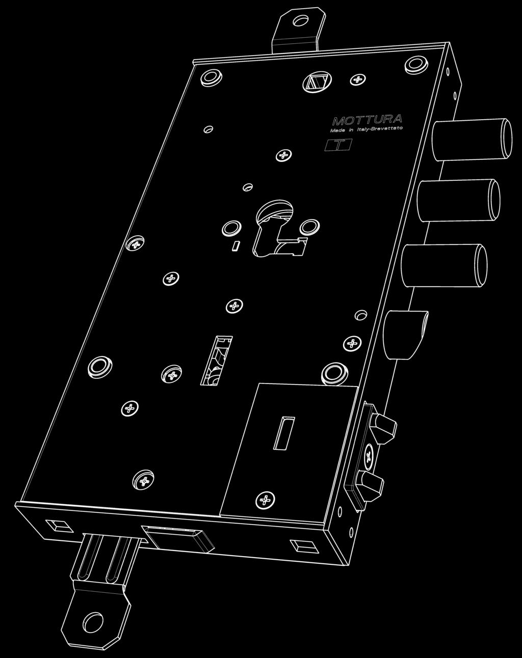
3 2 - INSTALLATION Fix the lock to the door structure by using all of the fasteners: side attachments (A), bushings (B) or mortise-type (C) (Fig. 1). In order to work correctly, the lock should be fixed in a vertical position. The lock may not work properly if installed or used in a different position. For correct operation of the lock, the spring latch must be able to protrude freely without frictioning when the door is open or closed. If necessary, drill spaces in the door structure to hold the battery pack in a non-binding position defined only by the length of the wires and by internal dimensions due to door configuration (switchlocks, etc.). Drill the frame for the door status sensor. For these drillings, see the attached mounting diagram in Fig. 2. If you are mounting switchlocks, always provide sufficient clearance between the bar and the upper and lower tabs both when the lock is open and when it is closed, so as to prevent strain that could damage the motor. Fasten the battery pack, if required, and wire as shown in the next paragraphs. Protect the lock before doing any work on the door that could produce waste material (soldering, drilling of panels, drilling of structure, etc.) that might enter the lock and impair its functioning. Do not insert the batteries into the battery holder until finished fixing to avoid short circuits that may damage the system. WARNING! When the door is completely mounted and perfectly positioned, run the first checks on the lock (opening/closing) in mechanical mode to make sure there is no frictioning on the levers (bars/switchlocks) or on the key when turning. These problems could impair correct electronic operation of the lock and cause permanent malfunction. Mottura Serrature di Sicurezza S.p.A. declines all liability if this procedure is not performed and, in such case, all warranties on the product will lapse. If a mains powered connection is provided, it is advisable to use grommet (not included) between fixed upright and leaf, attaching it as shown in the instructions attached to the grommet pack. A = SIDE ATTACHMENTS B = BUSHINGS C = MORTISE-TYPE B A A B C B B Fig.2 A A Fig. 1 3


, please see MOTTURA catalogs.")
4 2.1 - DRILLING DIAGRAM (CHANGEABLE POSITIONS) AND DIMENSIONS BOARD HOLDER EXTERNAL ELECTRO- NIC BOARD VERSION Variation in bolt centre distances 20 TOP 43 BOTTOM DETECTOR STRIKER DOOR ELECTRIC STRIKER BATTERY HOLDER DOUBLE TUBE VERSION Fig.2A BATTERY HOL- DER CASSETTE VERSION Fig CYLINDER FIXING For proper functioning of the lock, we recommend installation of a MOTTURA CHAM- PIONS double or half Europrofile cylinder (according to application) (DO NOT use cylinders with knobs). For better protection of the cylinder from the outer side of the door, we recommend the use of MOTTURA DEFENDER systems. For these articles (not included in the pack), please see MOTTURA catalogs. Alternatively use European cylinder with the dimension shown in the diagram GB - REV. 00

. Closing this contact for an interval from 0.5 to 2.0 seconds results in the lock operating. Connect cable 99.")

. cable 99 727 4 meters max.")
5 2.3 - VERSION QUICK RELEASE (CODE XT.G...) The version of the quick release lock provides the opening of the bolts by means of the handle. For proper installation, the locking plate must be secured to the lock on the outside, centered on the lower base and fasten the supplied screw M4. OUTSIDE plate screw 3 - CONNECTING CONTROL DEVICES You can operate the lock with a Normally Open button or with a device fit with a Normally Open voltage-free dry contact (not supplied) to be connected to the lock by means of the 10 cores cable (supplied). Closing this contact for an interval from 0.5 to 2.0 seconds results in the lock operating. Connect cable to the lock as shown on the following diagrams, using only two of the ten cores available: the purple one and the white one. DO NOT connect the cable using the other cores with color different from purple and white! For the use of the other eight colors contact Mottura Serrature di Sicurezza S.p.A. or view the following page. If the remote opening button/device is located more than 4 meters away from the lock, install a relay (not supplied) between the door and the device, with the coil connected to the remote control and the Common and Normally Open contacts of the relay connected to the lock with cable The cable has to run through a grommet (Art available on request). cable meters max. CONTROL DEVICE if longer than 4 meters cable CONTROL DEVICE cable RELAY TRANSFORMER GENERIC DEVICES (DRY CONTACT) You can operate and control the lock with several devices, all connected in parallel to each other. Devices must be connected to the lock by means of the 10 cores cable using only the purple and the white cores. See the installation manual supplied with the single control unit for information on its connection and use. Some devices are tested with IP54 protection grade. 5


 4 Yellow")

6 ART Other commercial devices, e.g.: - BADGE READER - TELEPHONE DIALER - KEYPADS - FINGERPRINT READERS - ALARM SYSTEMS - TAG READERS - ETC. 5 protection against dust and wire contact with dangerous parts. 4 protection against splashing water. ART ART Purple and white cores ART ART CABLE CABLE ART ART ART ART ART Other 8 cores of cable ART ART N.B. In the drawing it s not shown the power supply of the generic devices: refer to their specific manual PIN COLOR DESCRIPTION 1 White GND 2 Brown INPUT2 - Close 3 Green V internal (battery voltage or 9,5 Vmax from mains) 4 Yellow INPUT1 - Open 5 Gray OUTPUT3 - Door state 6 Pink OUTPUT5 - Low battery 7 Blue OUTPUT4 - Error 8 Red OUTPUT1 - Boltlatch state 9 Black OUTPUT2 - Latches state 10 Purple INPUT3 - Opening followed by automatic closing GB - REV. 00
: non-rechargeable alkaline batteries, mains, non-rechargeable alkaline batteries + mains.")


 and maximum lengths 4 meters, otherwise for upper cable section for lengths over meters.")

, it is mandatory to OPEN the jumper.")

7 4 - CONNECTING THE POWER SUPPLY Depending on the type of need, the XNOVA lock offers a number of options based on the type of power supply chosen for the system. POWER SUPPLY SYSTEM (with dedicated optional accessories): non-rechargeable alkaline batteries, mains, non-rechargeable alkaline batteries + mains. Before switching on the power supply and/or putting the batteries in their housings, make all of the connections and check that all wirings are correct. The AC/DC Adaptor (Art ) must be placed as close as possible to the door because it is always preferable to keep the 230 Vac main power cables long rather than the 12 Vdc lock power cables in order to minimize voltage drop on the cable. If you have to lengthen the lock power cables, never exceed 15 meters with a section of at least 1.5 mm2 (AWG15). The following table shows the possible power supply combinations, specifies the wiring diagram to be used for each, and lists the codes for wirings and the components used. WARNING! The electric cable is not provided, it must have a larger cross-section of 0.5 mm2 (AWG19) and maximum lengths 4 meters, otherwise for upper cable section for lengths over meters. We recommend to use coloured cables RED (positive) and BLACK (negative) to distinguish the polarity. STATE OF JUMPER Set the jumper according to the way in which it supplies power to mains and independently of the use of batteries. Lock supplied with CLOSED jumper, if the power supply is taken from the striker plate or if the lock is operated only by batteries, then nothing has to be done. If on the contrary, lock is operated directly by mains power (by cable), it is mandatory to OPEN the jumper. The jumper is located in the back of the lock below the connector of the battery protected by an adhesive label, and its state is described in detail in the wiring table. To OPEN the jumper, disconnect all 1 2 power supplies and batteries, be careful not to cause a short circuit between the outer casing of the lock and the electronic board. Remove the protection and pull out the jumper using the tweezers. WARNING! DO NOT CONNECT THE TWO CONTACTS OF THE STRIKER The connection CAN IRREVERSIBLY damage the device compromising the operation lock. XNOVA WIRINGS WIRINGS POWER SUPPLY ALKALINE BATTERIES MAINS ALKALINE BATTERIES + MAINS BATTERY PACK Fig. A Fig. C MAINS Fig. B Fig. C PATTERY PACK WIRING Wired tube battery pack battery pack wire Wired cassette battery pack Fig. A 7


8 WIRING MAINS POWERED AC / DC Adapter (see chapter 5) 230Vac 12Vdc grommet cable Fig. B WIRING MAINS POWERED + BATTERIES Wired tube battery pack Battery pack wire Wired cassette battery pack AC / DC Adapter (see chapter 5) grommet cable RED BLACK 230Vac 12Vdc POWER VIA GROMMET cable POWER VIA STRIKER cable NOT provided (red/black) N.B. The diagram represents a full installation where the batteries only serve in the event of a blackout. The lock can also be wired only to the MAINS POWER or exclusively by BATTERY power (cassette or double tube version). In the MAINS POWERED configuration, AC / DC Adapter must be installed outside the door. N.B. Make all connections with power swithed off and batteries disconnected GB - REV. 00
.")
9 5 - AC/DC ADAPTER CONNECTION (99.683) MECHANICAL FIXING The AC/DC adapter transforms the 230 Vac 50/60 Hz home power supply into a 12 Vdc isolated non-stabilized supply to power the lock. It can be fixed to the wall: the 2 slots on the bottom of the box allow it to be hooked to screws fixed to the wall (follow the drilling instructions on the bottom). As an alternative, the box can be hooked to a DIN guide (EN 60715) (not supplied) and snapped into place (black hook facing downward). To release it, pull the black hook downward with a flat-blade screwdriver ELECTRICAL CONNECTION All connections must be made by trained technical personnel in conformity to electrical safety standards and according to the Rules of Good Practice. INPUT: Connect the 230 Vac 50/60 Hz home power supply to input terminals L and N, inserting a cut-out and two-way switch up-line. Connect the ground of the power supply to the input terminal with the ground symbol. OUTPUT: Connect the lock power supply cable (code ) to the 12 Vdc output terminals, taking care to respect polarity (red to positive (+), black to negative (-)) to prevent permanent damage to the system. Double output terminals are provided ONLY to power any other Mottura devices. Using these terminals for any other purpose may permanently damage the system. MAIN 230Vac PHASE NEUTRAL GROUND LOCK 12Vdc POSITIVE + NEGATIVE - 9

10 REPLACING THE OUTPUT FUSE: the transformer is protected in output by a fuse. An integral fuse is indicated by the MAINS/RETE LED on the front panel; if the LED is off with power switched on, the fuse is blown. Before replacing the fuse, switch off the 230 Vac mains power supply and take all possible precautions to avoid electrical shock. Remove the terminal cover from the 12 Vdc OUTPUT side by inserting a small flat-blade screwdriver a few millimeters into the center housing on the cover, then gently tilt it from the other side of the box until the fastening tab is released. Remove the screwdriver and gently slide off the terminal cover with your hands. Remove the plastic cover of the fuse holder, remove and replace the fuse with one with the same rating (see technical data, paragraph 5.3). Reposition the terminal cover before switching voltage back on TECHNICAL DATA INPUT POWER SUPPLY VOLTAGE / FREQUENCY 230 Vac / Hz MAX. CURRENT DRAW MAX. POWER PROTECTION RATING < 0,105 A 24 VA IP10 (with terminals cover on) WORK TEMPERATURE Min. -10 C Max. +40 C ENCAPSULATED TRANSFOR- MER PROTECTION T A MECHANICAL WEIGHT 0.7 Kg DIMENSIONS MATERIAL 142 x 110 x 62 mm OUTPUT VOLTAGE 12 Vdc not stabilized IMPULSE ABSORPTION (5 sec. max.) FUSE Blend PC/ABS self-extinguishing UL94-V0 2 A DELAYED ACTION T 3,15 A (5 x 20) mm TERMINAL BOARD RATED SECTION OF CABLES 0,5 mm 2 (AWG20) to 2mm 2 (AWG12) GB - REV. 00
11 6 - OPERATION AND MAINTENANCE INSTRUCTIONS / USER MANUAL MAINS POWER SUPPLY If the lock is powered from the MAINS, you have to use an appropriately sized transformer. The MOTTURA transformer (AC/DC Adapter option Art with cable Art ) was subjected to tests on the lock to obtain the legally required certifications regarding immunity from electrical and electromagnetic noise as well as emissions to the mains and to the environment. Therefore, it must be used to power lock versions that require a transformer. The use of any transformer other than the one supplied (even for temporary testing), in addition to creating risk of damaging the lock or causing malfunctions, will immediately void all warranties. Mottura Serrature di Sicurezza S.p.A. will assume no liability for any harm/damage caused to persons or property BATTERY POWER SUPPLY If the lock is powered by BATTERIES, you have to use a battery pack (option Art or Art ). The system automatically checks the battery charge level at the start of every cycle. When the battery charge is no longer sufficient, correct operation of the lock is not guaranteed. In any case, you should replace the batteries once a year. Follow these instructions when replacing the batteries: Never use rechargeable batteries. Doing so will compromise operation of the lock. Mottura Serrature di Sicurezza S.p.A. assumes no liability for any type of malfunction, fault, and harm/damage caused to persons or property deriving from failure to observe the following instructions, which will also void the warranty. For alkaline batteries - 6x1.5V type D (LR20): replace all alkaline batteries promptly (or at least once a year) when the battery charge is no longer sufficient. Don t use Carbon Zinc batteries (R20). All of the batteries must be replaced at the same time, with new ones of the same brand and model. When replacing the 6 batteries, be extremely careful to respect their polarity in order to avoid permanent damage. The battery pack is available in two versions: double tube or cassette. ATTENTION: Drained batteries are harmful to the environment!! They must be disposed of in special containers found wherever batteries are sold, as required by law DOUBLE TUBE VERSION (Art ) To replace the batteries, open the door and insert a screwdriver (or a coin) in the notches on the two covers. Press gently and turn them counterclockwise until they come out, as shown in the figure. Remove the batteries (three in each tube). If the bottom battery doesn t come out, press on it gently with the screwdriver and release it suddenly so that the spring (which pushes from behind the battery) will expel it completely. Replace the batteries, inserting them with the negative pole (-) in the direction of insertion and the positive pole (+) facing the cover. When insertion is done, close the covers by repeating the above steps in the reverse order. 11
12 CASSETTE VERSION (Art ) To replace the batteries, open the door and loosen the screws on the front of the battery holder and then completely unscrew both screws, removing the front covering, so that the battery holder cassette is fully open, as shown in the figure. Pull the cassette out until it reaches the stop that prevents it from being completely extracted, then replace the batteries, positioning the new ones as shown on the bottom of the cassette. After replacing the batteries, reposition the cassette in its housing. Put the front cover back in place and tighten the fixing screws NOTES ON USING THE CYLINDER It is designed to overcome power failures or possible malfunctions of the electronic part. Therefore, it is preferable not to use it in normal operating conditions. It must never be used when the lock s electrical motor is working (opening/closing) TROUBLESHHOTING Possible anomalies of the lock and of its working are signaled by the OUT4 and OUT5 outputs of the ten core cable that will have a close state, meaning an error occurred. (for the other eight outputs of the cable contact Mottura or visit the web site). See the table below for the appropriate remedy. PROBLEM CAUSE REMEDY Output OUT4 closes for a generic error Output OUT5 closes for low battery level Possible mechanical seizing of latchbolts and bars during operation The spring latch does not return to its correct position, even after 5 seconds Lack of cylinder detected (only if the cylinder extraction protection system and cylinder detection sensor are present) The lock does not detect the correct position of bolts (latch and spring) The door status sensor does not detect the closed door The batteries begin to be discharged Check that the latchbolts and bars move freely; check that the door closes correctly and is mounted aligned. Check that the spring latch moves freely with the door both open and closed, and that the door is mounted aligned. Insert the cylinder in the lock. Open or close the lock so that the spring latch can protrude completely. Check that the lock and door status sensor are positioned according to the mechanical instructions supplied. Replace the batteries as soon as possible. IMPORTANT: If the cylinder is present, the mechanical key can always be used to open/close the door from outside and from inside. If the lock still malfunctions after you have made all necessary checks, you should call technical service or request a service call by an expert from an authorized Mottura Service Center. Under no circumstances should you attempt to do technical work on the lock unless you have the necessary knowledge of its parts. Remember that any repairs or maintenance done by unauthorized persons will immediately void all warranties and may cause permanent damage to the entire mechanical and/or electronic apparatus. Even more so, given the greater riskiness of main powered versions (230 VAC), it is essential to have electrical systems repaired and serviced by qualified, authorized personnel who must comply with all electrical safety standards. Mottura Serrature di Sicurezza S.p.A. declines all liability for any malfunction, fault, harm to individuals, or damage to property deriving from disregard of the above-mentioned rules GB - 05/18 - a_019540
INSTALLATION INSTRUCTIONS
 POWERED ELECTRONIC LOCK INSTALLATION INSTRUCTIONS RECHARGEABLE F 1.0 TABLE OF CONTENTS 1 - GENERAL INSTRUCTIONS... pag. 3 1.1 - WARRANTY TERMS 1.2 - LIMITS OF LIABILITY 2 - INSTALLATION... 4 2.1 - DRILLING
SPARE PARTS AND VARIOUS ACCESSORIES
 AND VARIOUS .066D/S Zinc-plated Plate (holes Ø6) + cylinder fastening screw for cylinder locks with Mottura fitting fixing The item is supplied left or right-hand (specify in the order).101n5 Bushing key
QUICK UNLOCKING AND REARMING LOCKS
 QUICK UNLOCKING AND REARMING LOCKS Security locks with 87.430T 87.440A Characteristics Locks for single and double cylinder. Three-points + Side (lower lock art. 87.440) Cylinder and handle backset 63
Installation and operating instructions. Solar charge controller MPPT 10 A / 20 A Z Z
 Installation and operating instructions Solar charge controller MPPT 10 A / 20 A EN 1 Contents 1. About these instructions... 3 1.1 Applicability... 3 1.2 Users... 3 1.3 Description of symbols... 3 2.
Switching DC Power Supply
 99 Washington Street Melrose, MA 02176 Phone 781-665-1400 Toll Free 1-800-517-8431 Visit us at www.testequipmentdepot.com Model 1693, 1694 Switching DC Power Supply INSTRUCTION MANUAL 1 Safety Summary
EC DECLARATION OF CONFORMITY
 EC DECLARATION OF CONFORMITY Manufacturer : Address: Declares that: FAAC S.p.A. Via Benini, 1-40069 Zola Predosa BOLOGNA - ITALY 844 T control board, conforms to the essential safety requirements of the
Art. No. EC-315. Art. No. EC-330. Art. No. EC-340 SWITCH-MODE BATTTERY CHARGER CONTENTS IMPORTANT SAFETY PRECAUTIONS... 2
 SWITCH-MODE BATTTERY CHARGER CONTENTS IMPORTANT SAFETY PRECAUTIONS... 2 DESCRIPTION AND FEATURES... 3 CHARGING STAGES... 4 Art. No. EC-315 Art. No. EC-330 Art. No. EC-340 PROTECTIONS... 5 INSTALLATION...
US - UP2/OIL 12V US - UP2/OIL 24V
 SELF PRIMING ELECTRIC PUMP FOR TRANSFERRING LUBRICATING OILS OR VISCOUS FLUIDS INSTRUCTIONS FOR USE 164 220 12-US - UP2/OIL 12V 164 220 13-US - UP2/OIL 24V 15/05/14 Rev.02 A PRODUCT DESCRIPTION Self-priming
Fuse state indicator MEg72. User manual
 Fuse state indicator MEg72 User manual MEg Měřící Energetické paráty, a.s. 664 31 Česká 390 Czech Republic Fuse state indicator MEg72 User manual Fuse state indicator MEg72 INTRODUCTION The fuse state
INSTRUCTIONS FOR THE RELIANCE Fast/Tran TM ARL0909 & ARL0909R
 INSTRUCTIONS FOR THE RELIANCE Fast/Tran TM ARL0909 & ARL0909R THE RELIANCE Fast/Tran IS NOT FOR "DO-IT-YOURSELF" INSTALLATION. It must be installed by a qualified electrician thoroughly familiar with all
ISTRUCTION MANUAL Italian Movements Italian Movements
 ISTRUCTION MANUAL CONTENTS OF MANUAL 1. General Information page 3 1.1 Introduction to this manual 2 Safety page 3 3. Technical Data page 5 3.1 Table of technical data and CE mark 4 Actuator page 6 4.1
SIZING OF SOLAR GENERATOR
 MULTI ISLAND is a water pumping system with power from photovoltaic panels. It is designed for use in water wells, irrigation systems, or the power supply network is not available, or when the user wishes
OPERATING INSTRUCTIONS PLEASE READ CAREFULLY
 OPERATING INSTRUCTIONS PLEASE READ CAREFULLY 925-0330 Rev 0 0416 TABLE OF CONTENTS SAFETY SUMMARY... 3 SPECIFICATIONS... 4 1.0 INTRODUCTION/DESCRIPTION.... 5 2.0 LOCATION AND MOUNTING... 5 3.0 CONNECTIONS
DC Master 24/ A
 USERS MANUAL DC Master 24/12 50-60A DC-DC converter MASTERVOLT Snijdersbergweg 93, 1105 AN Amsterdam The Netherlands Tel.: +31-20-3422100 Fax.: +31-20-6971006 www.mastervolt.com ENGLISH Copyright 2015
Mod: KLD6-12/35XLAS-N
 12/2011 Mod: KLD6-12/35XLAS-N Production code: 1914070 INSTRUCTION MANUAL LOGIC LINE PLUS HOOD Reseller Stamp for Warranty Dear customer, Above all, thank you for choosing our product and we would like
Installation and operating instructions. Solar charge controller 10 A / 15 A / 0 A / 30 A PHOTOVOLTAIK - PHOTOVOLTAICS - PHOTOVOLTAIQUE - FOTOVOLTAICA
 PHOTOVOLTAIK - PHOTOVOLTAICS - PHOTOVOLTAIQUE - FOTOVOLTAICA Installation and operating instructions Solar charge controller 10 A / 15 A / 0 A / 30 A EN 74.86 08.4 1. About this manual These operating
ELECTRONIC LOCKS AND BARS BLOCK POWERED ELECTRIC LOCKS
 49 ELECTRONIC LOCKS AND BARS BLOCK POWERED ELECTRIC LOCKS 49 49.M01/M21 Powered electronic locks Characteristics Lock for double cylinders Variation in centre distance:.../28 -.../37 BATTERY or MAINS operated
Type Operating Instructions. Bedienungsanleitung Manuel d utilisation. 2/2-Way Solenoid Valve 2/2-Wege-Magnetventil Électrovanne à 2/2 voies
 Type 5282 2/2-Way Solenoid Valve 2/2-Wege-Magnetventil Électrovanne à 2/2 voies Operating Instructions Bedienungsanleitung Manuel d utilisation 1 OPERATING INSTRUCTIONS The operating instructions contain
USER INSTRUCTIONS FOR SLIDING DOORS
 ENGLISH USER INSTRUCTIONS FOR SLIDING DOORS SL3L LIGHT SL4A ADVANCED SL5A ADVANCED SL5H HEAVY SLTA TELESCOPIC-ADVANCED SL4E EMERGENCY SL5E EMERGENCY SL5B BIG SLTE TELESCOPIC-EMERGENCY FACE S.p.A. Viale
Type Operating Instructions. Bedienungsanleitung Manuel d utilisation. 2/2-Way Solenoid Valve 2/2-Wege-Magnetventil Électrovanne à 2/2 voies
 Type 5282 2/2-Way Solenoid Valve 2/2-Wege-Magnetventil Électrovanne à 2/2 voies Operating Instructions Bedienungsanleitung Manuel d utilisation Contents 1 Operating Instructions... 2 2 Authorized use...
Owner's/Installation Manual
 Owner's/Installation Manual Power Management Module (PMM) and Starter Kit NOTE: The starter kit must be purchased and installed prior to individual PMM usage. Model Numbers: 00686-0 PMM 00699-0 PMM WITH
Valves. Rapid opening and closing solenoid valves VMR (E1110 rev /11/2012)
") Valves Rapid opening and closing solenoid valves VMR (E1110 rev. 03-19/11/2012) GENERAL WARNINGS: DISPOSAL: ¾ All installation, maintenance, ignition and setting must be performed by qualified staff, respecting
Valves Rapid opening and closing solenoid valves VMR (E1110 rev. 03-19/11/2012) GENERAL WARNINGS: DISPOSAL: ¾ All installation, maintenance, ignition and setting must be performed by qualified staff, respecting
2-PHASE STEPPING MOTOR DRIVER FE Z5 DISPENSE
 2-PHASE STEPPING MOTOR DRIVER FE Z5 DISPENSE For Diaphragm Dosing Pumps FEM 1.02_.55 / FEM 1.09_.55 Controller board package, without pump: ID 160536 Operating and Installation Manual It is important to
Powers TM Controls EA 338 Electronic Actuator
 Powers TM Controls Technical Instructions Document No. 155-136P25 EA 338-1 Description Features 24 Vac power supply. The s are used with floor mount linkage kits to operate dampers in HVAC installations.
GTS 15/25/40/50/60/75/90/120A
 GTS 15/25/40/50/60/75/90/120A POWER SOLID STATE RELAYS WITH LOGIC CONTROL Vdc / Vac Main applications Plastic extrusion lines and injection presses Packing and packaging machines Polymerization and production
PURE SINE WAVE DC TO AC POWER INVERTER
 PURE SINE WAVE DC TO AC POWER INVERTER 60S-12A / 60S-24A 60S-12E / 60S-24E 100S-12A / 100S-24A 100S-12E / 100S-24E 150S-12A / 150S-24A 150S-12E / 150S-24E Instruction manual SINE WAVE INVERTER Please read
USE AND INSTALLATION HANDBOOK
 Date : 10/02/14 Rev. 01 PR.T : FG006172 USE AND INSTALLATION HANDBOOK DUPLEX-UP CONTROL PANEL FOR 2 ELECTRIC PUMPS WITH CURRENT CONTROL. DUPLEX-UP Via Enrico Fermi 8-35020 Polverara PD Tel.049/9772407
Compact Heat Meters. Features. -A Pulsed output. -B M-Bus output. Accessories. UK Sales Tel: International Tel:
 Compact Heat Meters Features Compact design Simple operation Pulsed output Measures heating or cooling Specification Product Codes Water Meter Temp. range 10 to 90 C Nominal pressure 16bar Installation
User Manual. NetGuard IMPORTANT. PSD 650/1200/1600 Line Interactive UPS Uninterruptible Power Supply System. UPS Monitoring Software
 User Manual Thank you for purchasing the Defender 650/1200/1600. It is designed to provide safe and reliable power protection to your precious electronics equipment. Before you start using the product,
EC MACHINE DIRECTIVE COMPLIANCE DECLARATION
 770 EC MACHINE DIRECTIVE COMPLIANCE DECLARATION (DIRECTIVE 89/392 EEC, APPENDIX II, PART B) Manufacturer: FAAC S.p.A. Address: Via Benini, 1 40069 - Zola Predosa BOLOGNA - ITALY Hereby declares that: the
Automatic concealed bollards 275 H600 and 275 H800 with pit
 Automatic concealed bollards 275 H600 and 275 H800 with pit Technical installation manual CE Declaration of conformity Warnings for the installer Bollard technical data Preparing and installing the bollard
Corso Principi di Piemonte, 65/ RACCONIGI (CN) ITALY tel fax
 ITALY tel fax") V2 S.p.A. Corso Principi di Piemonte, 65/67 12035 RACCONIGI (CN) ITALY tel. +39 01 72 81 24 11 - fax +39 01 72 84 050 info@v2home.com - www.v2home.com IL n.131 EDIZ. 28/08/2012 Bingo I GB F E P D NL ATTUATORE
V2 S.p.A. Corso Principi di Piemonte, 65/67 12035 RACCONIGI (CN) ITALY tel. +39 01 72 81 24 11 - fax +39 01 72 84 050 info@v2home.com - www.v2home.com IL n.131 EDIZ. 28/08/2012 Bingo I GB F E P D NL ATTUATORE
SOLAR CHARGE CONTROLLER
 SOLAR CHARGE CONTROLLER SCE 1010 / SCE 1515 / SCE 2020 / SCE 3030 Instruction Manual Please read user manual carefully before use. 1.About this manual These operating instructions are part of the product.
Ex m Solenoid Operator Type 0519
 nass magnet GmbH Eckenerstrasse 4-6 D-30179 Hannover Doc. No. 113-720-0002 Revision No. 2 01.06.2015 Ex m Solenoid Operator Type 0519 Operating Instructions Dear Customer! To ensure the function and for
Table of Contents. General Safety Preparation for Installation Parts List Optional Accessories Part List... 5
 REV 12a Table of Contents General Safety....... 2 Preparation for Installation....... 3 Parts List....... 4 Optional Accessories Part List...... 5 Technical Specifications & Feature...... 5 Installation
OWNER'S MANUAL. Royal Sovereign International Inc. RET Desk Series
 OWNER'S MANUAL RET Desk Series Read all instructions carefully before use. For any Customer Support needs please choose the Customer Support tab on www.royalsovereign.com Royal Sovereign International
MSD Kawasaki Jet Ski 750 Enhancer CD Ignition PN 4251
 MSD Kawasaki Jet Ski 750 Enhancer CD Ignition PN 4251 Parts Included: 1 - MSD Enhancer CD Ignition 2-6mm Stainless Steel Flatwashers 2 - Zip Ties Supplies Required For Installation 1 Tube of Blue Loctite
Users Manual. Defender 1 8.0KW to 14.0KW Online Emergency Lighting Inverter. Technical Manual # Revision B
 Users Manual Defender 1 8.0KW to 14.0KW Online Lighting Inverter Technical Manual #018-0102-01 Revision B Phone: 1.877.DSPM.POWER 1.877.377.6769 Fax: 909.930.3335 Website: www.dspmanufacturing.com E-Mail:
INSTALLATION AND OWNER S MANUAL MODEL ASW Actuator Swing Gate Operator
 INSTALLATION AND OWNER S MANUAL MODEL ASW Actuator Swing Gate Operator Serial #: Date Installed: Your Dealer: READ THIS MANUAL CAREFULLY BEFORE INSTALLATION OR USE. SAVE THESE INSTRUCTIONS. Introduction
Triple Output Power Supply
 Test Equipment Depot - 800.517.8431-99 Washington Street Melrose, MA 02176 TestEquipmentDepot.com Model 1672, 1673 Triple Output Power Supply INSTRUCTION MANUAL 1 Safety Summary The following safety precautions
Multi-Mover Charger for model L25
 Multi-Mover Charger for model L25 Important safety instruction. Keep these instructions. This manual contains important instructions for the safety of the user and the operation of the device. 1. SYMBOLS
BMRX Series ROTARY LEVEL CONTROL
 BMRX Series ROTARY LEVEL CONTROL OPERATING INSTRUCTIONS PLEASE READ CAREFULLY 925-0292 Rev C TABLE OF CONTENTS GENERAL SPECIFICATIONS... 3 SAFETY SUMMARY... 4 1.0 INTRODUCTION... 5 2.0 INSTALLATION...
INSTRUCTION AND USE MANUAL
 CONTROL UNITS FOR ENGINE CONTROL AND PROTECTION TYPE CEP-090 INSTRUCTION AND USE MANUAL It is equipped with display to show the INSTRUMENTS: - hour-meter - fuel level indicator - tachometer - battery voltmeter
Outdoor UPS. User Manual. Contents. Please read carefully this manual before installing and using this product. 1 Introduction Safety...
 Contents 1 Introduction...1 2 Safety...4 3 Product Specifications...6 Outdoor UPS User Manual 4 Installation...8 4.1 Inspection...8 4.2 Installing the UPS Cabinet...8 4.3 Connecting the Power Supply...10
Compact System NRGS 11-2 NRGS Original Installation Instructions English
 Compact System NRGS 11-2 NRGS 16-2 EN English Original Installation Instructions 810366-05 1 Contents Important Notes Page Usage for the intended purpose...4 Safety note...4 LV (Low Voltage) Directive
User s Manual. Automatic Switch-Mode Battery Charger
 User s Manual Automatic Switch-Mode Battery Charger IMPORTANT Read, understand, and follow these safety rules and operating instructions before using this battery charger. Only authorized and trained service
CONTROL AND PROTECTION PANEL FOR TRACTOR-PUMP CTR-087/0N THE TRACTOR/PUMP IS STOPPED WHEN THERE ARE ANOMALIES (VIA ELECTROMAGNET) CONCERNING:
 CONCERNING:") CONTROL AND PROTECTION PANEL FOR TRACTOR-PUMP TYPE CTR-087/0N INSTRUCTION AND USER MANUAL NEVER USE THE DEVICE WHEN THE TRACTOR IS IN MOVEMENT THE TRACTOR/PUMP IS STOPPED WHEN THERE ARE ANOMALIES (VIA
CONTROL AND PROTECTION PANEL FOR TRACTOR-PUMP TYPE CTR-087/0N INSTRUCTION AND USER MANUAL NEVER USE THE DEVICE WHEN THE TRACTOR IS IN MOVEMENT THE TRACTOR/PUMP IS STOPPED WHEN THERE ARE ANOMALIES (VIA
USER S MANUAL GPC SERIES LOW VOLTAGE DISCONNECT. Galley Power LLC.
 USER S MANUAL GPC SERIES LOW VOLTAGE DISCONNECT Galley Power LLC www.galleypower.com Table of Contents Safety Notice... 3 Disclaimer... 3 Safety Instructions... 4 1. Introduction... 5 1.1 Features and
EStrong-series Emergency Stop
 Original instructions EStrong-series Emergency Stop ABB AB / Jokab Safety Varlabergsvägen 11, SE-434 39 Kungsbacka, Sweden www.abb.com/jokabsafety Read and understand this document Please read and understand
Tina 10A/B/C Adaptor unit
 Original instructions Tina 10A/B/C Adaptor unit ABB Jokab Safety Varlabergsvägen 11, SE-434 39 Kungsbacka, Sweden www.abb.com/jokabsafety Read and understand this document Please read and understand this
Instruction, Use and Maintenance Manual CONTROL UNITS J-GIOTTO TOP
 CONTROL UNITS J-GIOTTO TOP Bardiani Valvole S.p.A. via G. di Vittorio, 50/52-43045 Fornovo di Taro (PR) - Italy tel. +39 0525 - Fax 0525 3408 bardiani@bardiani.com - www.bardiani.com MANUAL REVISION DATE
5 IN 1 JUMP START OPERATION & MAINTENANCE INSTRUCTIONS MODEL NO: JS5IN1 PART NO: LS0810
 5 IN 1 JUMP START MODEL NO: JS5IN1 PART NO: 6240005 OPERATION & MAINTENANCE INSTRUCTIONS LS0810 INTRODUCTION Thank you for purchasing this CLARKE product. Before attempting to use this product, please
OPERATING MANUAL PHASE SEQUENCE AND MOTOR ROTATION DIRECTION TESTER TKF-13
 OPERATING MANUAL PHASE SEQUENCE AND MOTOR ROTATION DIRECTION TESTER TKF-13 v1.5 07.07.2011 Table of contents 1. Safety measures... 2 2. Phase spin direction test... 3 3. Motor shaft spin direction (using
OpenAir Electric Damper Actuators GDE/GLB Series Non-spring Return Rotary 24 Vac - Modulating Control 0 to 10 Vdc
 Technical Instructions Document No. 155-187P25 EA GDE/GLB-1 OpenAir Electric Damper Actuators GDE/GLB Series Non-spring Return Rotary 24 Vac - Modulating Control 0 to 10 Vdc Description The OpenAir direct
EC MACHINE DIRECTIVE COMPLIANCE DECLARATION
 EC MACHINE DIRECTIVE COMPLIANCE DECLARATION (DIRECTIVE 89/392 EEC, APPENDIX II, PART B) Manufacturer: FAAC S.p.A. Address: Via Benini, 1 40069 - Zola Predosa BOLOGNA - ITALY Hereby declares that: the 770
ENGINE PROTECTION BOARD PDM1
 ENGINE PROTECTION BOARD REFERENCE MANUAL. Standard of reference: IEC/EN 60255-6 IEC/EN 61000-4-2 IEC/EN 61000-4-3 IEC/EN 61000-4-4, IEC/EN 61000-4-5 IEC/EN 61000-4-6 IEC/EN 55011 IEC/EN 60028-2-61 IEC/EN
SARGON S - M - L. All rights reserved INSTALLATION MANUAL
 INSTALLATION MANUAL Our compliments for your excellent choice. SARGON LINE S (300mm) M (400mm) and L (600mm) electro-mechanical gear motor has been produced for reliability and high quality. This Manual
AWZ 200. AWZ 13,8V/2A/7Ah/L
 GREY POWER AWZ 200 v.2.4 AWZ 13,8V/2A/7Ah/L Linear, Buffer Power Supply Unit EN** Edition: 7 from 15.05.2014 Supercedes the edition: 6 from 13.02.2014 Features: 13,8VDC/2A uninterruptible supply fitting
WELDING INVERTER. PEGAS 160 E Smart PEGAS 200 E Smart OPERATING MANUAL. ALFA IN a.s. PEGAS E Smart Manual EN 04
 WELDING INVERTER PEGAS 160 E Smart PEGAS 200 E Smart OPERATING MANUAL PEGAS 160-200 E Smart Manual EN 04 2/12 CONTENT: 1. INTRODUCTION... 3 2. SAFETY INSTRUCTIONS AND WARNINGS... 4 3. TECHNICAL DATA...
USE AND MAINTENANCE MANUAL. J-Giotto-Top GB-IST-JGIOT-0112
 USE AND MAINTENANCE MANUAL J-Giotto-Top GB-IST-JGIOT-0112 Table of Contents 1. Symbols used...3 2. Safety instructions...3 3. Structure and functions of J-Giotto Top...4 4. Technical data...5 5. Installation...7
USB Charge Port Installation Instructions
 USB Charge Port Installation Instructions Lifetime Technical Support support@logolites.com 770-476-7322 www.logolites.com Manual 100-0014C Thank you for purchasing a Logo Lites USB Charge Port! USB Charge
230V DIESEL FUEL TRANSFER PUMP MODEL NO: DFT230
 230V DIESEL FUEL TRANSFER PUMP MODEL NO: DFT230 PART NO: 7160050 OPERATION & MAINTENANCE INSTRUCTIONS GC0816 INTRODUCTION Thank you for purchasing this CLARKE Pump. The DFTP230 pump is a self-priming rotary
The best in security is at your fingertips
 M. 2.0 The best in security is at your fingertips 1 safeguarding your security Protect your house with the best possible security, with optimised ease of use. X MODE M2.0 is the solution The perfect balance
Uninterruptible power supply Supply MEg101.4
 Uninterruptible power supply Supply MEg101.4 MEgA Měřící Energetické Aparáty, a.s. 664 31 Česká 390 Czech Republic Uninterruptible power supply Supply MEg101.4 Uninterruptible power supply MEg101.4 1/
Operating Instruction Manual of Energy Management System EBL 208, Art.-No Seite 1 / 7
 EBL 208, Art.-No 911.430 Seite 1 / 7 Contents 1. Description 2. Safety Information 3. Operating Instructions 4. Transport, Storage, Installation 5. Electrical Installation 6. Power-Up, Shut-Down, Maintenance
Tina 11A Connection block
 Original instructions Tina 11A Connection block ABB Jokab Safety Varlabergsvägen 11, SE-434 39 Kungsbacka, Sweden www.abb.com/jokabsafety Read and understand this document Please read and understand this
Tina 4A Connection block
 Original instructions Tina 4A Connection block Instructions valid for versions of the product from ver. H ABB Jokab Safety Varlabergsvägen 11, SE-434 39 Kungsbacka, Sweden www.abb.com/jokabsafety Read
HOYMILES MICRO-IVERTER MI-250
 HOYMILES MICRO-IVERTER MI-250 TECHNICAL MANUAL CONTENTS INTRODUCTION... 3 SAFETY... 4 SYMBOL ILLUSTRATION... 4 INSTALLATION WARNINGS... 5 PREPARE FOR INSTALLING... 6 TRANSPORT AND INSPECT... 6 CHECK INSTALLATION
JET METER INSTRUCTIONS
 UNPACKING Please open and inspect your package upon receipt. Your package was packed with great care and all the necessary packing materials to arrive to you undamaged. If you do find an item that is broken
ARC 1850 LIST OF FIGURES
 PAGE 1.0 INTRODUCTION... 1 2.0 WARRANTY... 1 3.0 UNPACKING YOUR UNIT... 1 4.0 SUGGESTED SAFETY PRECAUTIONS...... 1 4.1 PERSONAL SAFETY PRECAUTIONS. 1 4.2 POWER SUPPLY SAFETY PRECAUTIONS.. 2 5.0 GENERAL
BM kv Digital Insulation Tester USER MANUAL
 M BM5200 5 kv Digital Insulation Tester USER MANUAL CONTENTS Safety warnings...3 Symbols used on instrument...4 Cleaning...4 General description...5 Insulation resistance test modes...5 Automatic discharge...5
Owner s Manual. PowerVerterDC-to-AC Inverter
 Owner s Manual PowerVerterDC-to-AC Inverter Model: PV700HF Input V DC Output 0V, 60Hz AC Reliable AC Power Wherever You Need It Congratulations! You've purchased a high-quality Inverter designed to function
VD4 Installation and service instructions kv A ka
 Medium voltage products VD4 Installation and service instructions 12... 36 kv - 630... 3150 A - 16... 50 ka Index For your safety! 1 I. Introduction 2 II. Programme for environmental protection 2 1. Packing
Datasheet PDCSY-MW-CHM. Technical Overview. Features. Product warranty and total quality commitment. General Information.
 Datasheet Compact Heat Meters Technical Overview Heat energy is calculated by using a matched pair of high accuracy sensors to measure the difference between the forward and flow temperatures. The amount
Operations Manual. Zero Speed Switch Sensor Model ZS09P
 Zero Speed Switch Sensor Model ZS09P The must be referred to for correct installation. Failure to comply with the shall void all warranties and liabilities. Overview The Phares Electronics Model ZS09P
c-go 24V/6A 24V/8A 24V/12A
 c-go 24V/6A 24V/8A 24V/12A Battery charger GB Instruction manual 1 Index 1. Product description... 2 2. Safety advices... 3 3. Quick start guide... 4 4. Operation... 4 5. Problem solving... 6 6. Specifications...
SCOPELITE TIMING LIGHT OPERATING MANUAL
 SCOPELITE TIMING LIGHT OPERATING MANUAL MOTORTECH Tools & Test Equipment for Ignition Systems P/N 01.10.020-EN Rev. 11/2015 Copyright Copyright 2015 MOTORTECH GmbH. All rights reserved. Distribution and
Sense7-series Non-contact coded safety switch
 Original instructions Sense7-series Non-contact coded safety switch ABB AB / Jokab Safety Varlabergsvägen 11, SE-434 39 Kungsbacka, Sweden www.abb.com/jokabsafety Read and understand this document Please
OPERATING AND MAINTENANCE MANUAL. Primary Current Injection Test Set. 750ADM-H mk2
 OPERATING AND MAINTENANCE MANUAL Product: Type: Primary Current Injection Test Set 750ADM mk2 750ADM-H mk2 DESIGNED AND MANUFACTURED BY: T & R Test Equipment Limited 15-16 Woodbridge Meadows, Guildford,
USE AND MAINTENANCE MANUAL
 LATERAL TURNOVER 360 ORIGINAL INSTRUCTIONS INTRODUCTION This manual includes instructions for assembly, maintenance (regular and extraordinary), and for possible faults with remedies. The instructions
Model 1672, 1673 Triple Output Power Supply
 Model 1672, 1673 Triple Output Power Supply INSTRUCTION MANUAL 1 Safety Summary The following safety precautions apply to both operating and maintenance personnel and must be observed during all phases
TECHNICAL MANUAL. Inverter / Charger Combi. Combi SW 12V 1600VA Réf : PF Combi SW 24V 3800VA Réf : PF NOT_COMBI_SW-00
 TECHNICAL MANUAL EN Inverter / Charger Combi Combi SW 12V 1600VA Réf : PF.16088 Combi SW 24V 3800VA Réf : PF.16089 SAFETY PRECAUTIONS TO PREVENT ANY RISK OF ELECTRIC SHOCK OR FIRE, READ THIS MANUAL CAREFULLY
Installation manual Complete set active Sound incl. Soundbooster Skoda Octavia 5E
 Version 1.04 (01.06.2017) Installation manual Complete set active Sound incl. Soundbooster Skoda Octavia 5E Articel no. 40590 www.kufatec.de Kufatec GmbH & Co. KG Dahlienstr. 15 23795 Bad Segeberg e-mail:
Car Battery Charger Instructions for Use
 BATTERY CHARGER 12Volt 4Amp FOR INDOOR USE ONLY Power Details: Input: 230-240Vac; 50Hz; 52W Output: 12V DC; 2.8A Maximum Charge Rate: 4A RMS Read these instructions before operating this car battery charger
Installation and operating instructions. Solar charge controller Solarix MPPT 1010 and Z Z
 Installation and operating instructions Solar charge controller Solarix MPPT 1010 and 2010 EN 730927 Z04 1440 730927 Z04 1440 1 Contents 1. About these instructions...3 1.1 Applicability...3 1.2 Users...3
MKey9-series Safety Interlock Switch with Guard Locking
 Original instructions MKey9-series Safety Interlock Switch with Guard Locking ABB AB / Jokab Safety Varlabergsvägen 11, SE-434 39 Kungsbacka, Sweden www.abb.com/jokabsafety Read and understand this document
zelsius Installation and operating manual All that counts. EnergyMetering
 EnergyMetering zelsius Installation and operating manual Electronic compact heat meter with single jet flow sensor M-Bus and 2 inputs/outputs optional qp 0.6/1.5/2.5 m³/h All that counts. General information
IRREVERSIBLE OPERATOR FOR SWING GATES AND DOORS
 VH IRREVERSIBLE OPERATOR FOR SWING GATES AND DOORS WARNING!! Before installing, thoroughly read this manual that is an integral part of the pack Our products if installed by qualified personnel capable
Contents. EC DECLARATION OF CONFORMITY FOR MACHINES... p. 10. WARNINGS FOR THE INSTALLER... p. 10
 Contents EC DECLARATION OF CONFORMITY FOR MACHINES... p. 10 WARNINGS FOR THE INSTALLER... p. 10 1. DESCRIPTION AND TECHNICAL SPECIFICATIONS... p. 11 1.1. DIMENSIONS... p. 11 2. ELECTRIC DEVICES (standard
ECONOMISER SERIES E2T USER MANUAL
 TURBO S.R.L. Electronic Control Systems for Dust Collectors e-mail: info@turbocontrols.it web: www.turbocontrols.it TEL. ++39 (0)362 574024 FAX ++39 (0)362 574092 ECONOMISER SERIES E2T USER MANUAL 24/06/2014
FHC-1D user manual. Features
 Phason The Fan and Heater Control (FHC-1D) automatically controls the temperature in a room by adjusting the speed of variable speed fans and controlling a heater interlock. When the temperature is at
II DISTRIBUTION & SUBSTATION TYPE C
 CapCheckIII DISTRIBUTION & SUBSTATION TYPE Ca p a c i t o r C h e c ke r Operating & Instruction Manual 1475 Lakeside Drive Waukegan, Illinois 60085 U.S.A. 847.473.4980 f a x 8 4 7. 4 7 3. 4 9 8 1 w e
c-go 12V/10A 12V/20A Power supply and battery charger Instruction manual
 c-go 12V/10A 12V/20A Power supply and battery charger GB Instruction manual 1 Index 1. Product description... 2 2. Safety advices... 3 3. Mounting and installation... 4 4. Operation... 5 5. Problem solving...
Instruction, Use and Maintenance Manual CONTROL UNITS GIOTTO TOP
 CONTROL UNITS GIOTTO TOP Bardiani Valvole S.p.A. via G. di Vittorio, 50/52-43045 Fornovo di Taro (PR) - Italy tel. +39 0525 - Fax 0525 3408 bardiani@bardiani.com - www.bardiani.com MANUAL REVISION DATE
Electrically Released Brakes ERS VAR11-01 FT = 4100 N
 SM429gb - rev 06/11 S E R V I C E Electrically Released Brakes ERS VAR11-01 FT = 4100 N M A N U A L EC type certificate ABV 775/1 According to drawing 1 12 106946 TUV SUD Industrie Service WARNER ELECTRIC
ACSI MODEL 1406BB-04-AO POWER SUPPLY INSTALLATION INSTRUCTIONS
 II 1400-10 ACSI MODEL 1406BB-04-AO POWER SUPPLY INSTALLATION INSTRUCTIONS Features: Up to 1.95 Amps Load Capacity Class 2 Rated Outputs Overload, Over Voltage, and Short Circuit Protection Standby Battery
SLIDE & OL USER'S AND INSTALLER'S MANUAL V1.0 REV. 06/2017
 SLIDE & OL USER'S AND INSTALLER'S MANUAL V1.0 REV. 06/2017 00. CONTT 01. SAFETY INSTRUCTIONS INDEX 01. SAFETY INSTRUCTIONS STANDARDS TO FOLLOW 02. OPERATOR TECHNICAL SPECIFICATIONS DESCRIPTION DIMSIONS
KeContact P20. User manual
 KeContact P20 User manual Comments to this manual In this manual you will find warnings against possible dangerous situations. The used symbols apply to the following meanings:!! WARNING! Indicates a potentially
Cruising Charger Series OWNER S MANUAL
 R Cruising Charger Series OWNER S MANUAL ON BOARD BATTERY CHARGERS Models DC Amperage No. Of Banks Volts 2614A 5,10 Amps 2 Bank 12/12 2614A-230 2621A 5,5,10 Amps 3 Banks 12/12/12 2621A-230 2622A 10,10
L /2012 rev 0 BISON 30 OTI UNIONE NAZIONALE COSTRUTTORI AUTOMATISMI PER CANCELLI, PORTE SERRANDE ED AFFINI
 L8542968 07/2012 rev 0 BISON 30 OTI UNIONE NAZIONALE COSTRUTTORI AUTOMATISMI PER CANCELLI, PORTE SERRANDE ED AFFINI 1 458 250 A F 645 477 B 195 470 270 2 C 13 ±5 156 70 2 3 4 D2 R D2 I D1 T 5 W D H G R