Silverline. S210 Operators Manual Rev: 211
|
|
|
- Philippa Wilkins
- 5 years ago
- Views:
Transcription


1 Silverline by S210 Operators Manual Rev: 211
2 Table of Contents Machine Warranty Page 1 Safety Instructions Pages 2 4 Installation Pages 5 Technical Features Pages 5 Transportation and Installation Pages 5 6 Safety Precautions Pages 6 7 Machine Configuration Page 7 Machine Operation Pages 8-27 Tire Mounting Page 28 Error Indication Page 29 General Troubleshooting Page 30 Standard and Optional Accessories Page 31 Maintenance Pages Electrical Drawings Pages 34 35
3 Warranty This warranty will cover parts, labor and mileage up to 6 months for any mechanical machine part that fails due to manufacturing. Excluded from the warranty are all normal wear and consumable items. (bead-breaking bumpers, hoses and all plastic accessories) Any machine damage incurred during shipping is not the responsibility of the manufacturer or seller. (Any damage incurred during shipping is the responsibility of the Freight Company) Any damaged or injury caused by operator error, misuse, lack of maintenance or faulty utilities (electrical or air supply) is not the responsibility of the manufacturer or seller. For all of your service and parts needs please contact Wheel Products by McCourt at
4 Introduction: The purpose of this manual is to provide the owner and operator of this machine with a set of safe and practical instructions for the use and maintenance of the wheel balancer. If such instructions are carefully followed, the machine will offer you the levels of efficiency and duration. The following paragraphs define the levels of danger regarding the machine. DANGER: Refers to immediate danger with the risk of serious injury or death WARNING: Dangerous or unsafe procedures that can cause serious injury or death The instructions and information described in this manual must always be complied with: the operator will be held responsible for any operation not specially described and authorized in this manual. Some of the illustrations contained in this booklet have been taken from pictures of prototypes: standard production machines may differ slightly in certain respects. These instructions are for the attention of personnel with basic mechanical skills. We have therefore condensed the descriptions of each operation by omitting detailed instructions regarding, for example, how to loosen or tighten the fixing devices. Do not attempt to perform operations unless properly qualified or with suitable experience. If necessary, please contact an authorized Service Center for assistance. Installation: ATTENTION: Dangerous or unsafe procedures that can cause minor injuries or damage to property. Read these instructions carefully before using the machine. Keep this manual and the illustrated materials supplied with the equipment in a folder near the place of operation so as to allow the machine operators to consult the documentation at any time. The manual is only to be considered valid for the machine serial number and model stated on the attached nameplate. Take the utmost care when unpacking, assembling, lifting and setting up the machine as indicated below. Failure to observe these instructions can damage the machine and compromise the operator's safety. Remove the original packing materials after positioning them as indicated on the packaging. All regulations in force concerning safety at work must be complied with when choosing the installation position. In particular, the machine must only be installed and operated in protected environments where there is no risk of exposure to water or liquids. 2
5 IMPORTANT: for the correct and safe operation of the machine, the lighting level in the place of operation should be at least 300 lux. Environmental operating conditions must comply with the following requirements: - Relative humidity ranging from 30% to 80% (without condensation); - Temperatures ranging from 23 to +122 F. The floor must be strong enough to support a load equal to the weight of. the equipment plus the maximum load allowed The machine must not be operated in potentially explosive atmospheres Safety Regulations Failure to comply with the instructions and danger warnings can cause serious injuries to the operator or other persons. Do not operate the machine until you have read and understood all the danger/warning notices in this manual. The correct use of this machine requires a qualified and authorized operator. This operator must be able to understand the manufacturer's written instructions, be suitably trained and be familiar with the safety procedures and regulations. Operators are forbidden to use the machine under the influence of alcohol or drugs that could affect his/her physical and mental capacity. The Following Conditions are Essentia - Read and understand the information and instructions described in this manual; - Have a thorough knowledge of the features and characteristics of the machine; - Keep unauthorized persons well clear of the working area; - Make sure that the machine has been installed in compliance with all relevant standards and regulations in force; - Make sure that all machine operators are suitably trained, that they are capable of using the machine correctly and safely and that they are adequately supervised during work; - Do not touch power lines or the inside of electric motors or any other electrical equipment before making sure they have been powered off; - read this booklet carefully and learn how to use the machine correctly and safely; - Always keep this user manual in a place where it can be readily consulted and do not fail to refer to it. Do not remove or deface the DANGER, CAUTION, WARNING or INSTRUCTION decals. Replace any missing or illegible decals. If any decals have become detached or damaged, it is possible to obtain them from your nearest reseller. -Observe the unified industrial accident prevention regulations relating to high voltages and rotating machinery whenever the machine is in use or being serviced. - Any unauthorized changes or modifications made to the machine automatically release the manufacturer from any liability in the case of damage or accidents resulting from such changes or modifications. 3


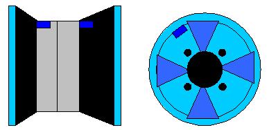
6 Wear Protective Gloves Read Operations Manual Wear Protective Glasses Power off the Electrical Source of the Machine during Maintenance Lightning - This decal, positioned on the back of the machine, indicates where to insert the power supply cable and warns the user to pay attention to his safety. Warning for rotating machine part This decal, positioned next to the balancing shaft, reminds the user that this is a rotating part and is therefore dangerous and should not be touched with the hands. The arrow indicates the rotation direction. Grounding - positioned on the rear left side of the machine, indicates where to connect the ground wire. 4
7 Installation & Operation Before installation and use of the wheel balancer, you should carefully read this installation and operation manual. The manual should be kept for future reference. Operators should be familiar with this instruction manual to ensure correct operation and safety. Ground wire is necessary for the correct operation. Do not use these as a ground source (air pipes, water pipes, telephone line and other unsuitable objects.) 2.1Protective Cover Installation: 2.2Main Shaft Installation 3.0 Technical Features 3.1 FEATURES It must be ensured the machine is grounded correctly to earth. If not, contact your local distributor. FIG 1 This manual must be grounded with reliable earth wire. 2.3 Electrical Connection and Earthing All electrical connections must be carried out by a qualified electrician. If in doubt, contact your local distributor. Make sure the technical parameter shown on the machine is comparable with the power supply. This machine must be fitted with 13Amps fuse. The voltage stabilizer is recommended to be installed in the power supply. Any electrical connection to be carried out by a qualified electrician and must comply with all standard regulations. Power voltage on the data plate on the machine; Voltage decrease cannot exceed 4% of the rated voltage on the data plate when fully loaded (10% at startup) It is recommended the machine is installed with a 30ma circuit breaker and voltage stabilizer in area where supply voltage cannot be guaranteed; To prevent the unauthorized use of the machine it is recommended to disconnect the machine from the power supply Low noise, wear resistant bearing for high precision Computerized wheel balancer with dynamic, static multiple ALU modes and ALU mode for motorcycle Self-calibration and automatic trouble diagnosis 3.2 Main Technical Specification rated voltage (selectable) 60HZ power 250W Average balancing time 7S (20KG wheel) Accuracy + 2g Noise < 69dB Rim Diameter Maximum wheel weight 154 lbs (70KG) Rim width Net Weight 246 lbs (112KG) Max wheel diameter 39inch (1000mm) working environment temperature 32 F F (0 C to +50 C), relative humidity: 30% 80% (no condensation); 4.0 Transportation & Installation 4.1 Transportation Place, carry and store the machine according to the indication of the label on the packaging. Store environment: RH20%-95% temperature - 14 F to +140 F (10 C to +60 C) When transporting or using the machine do no lift or impact the shaft as it will cause permanent damage. 5


8 \ FIG Packaging materials must be disposed in accordance with environmental regulation for the region. Remove all packaging and check contents with below list of items. If any parts are missing or damaged, please contact your distributor. 4.2 Installation Position the wheel balancer in the desired area for use. Be sure the floor is leveled and of solid construction. The wheel balancer is designed for operation indoors and should not be exposed to moisture or direct sunlight. Transport the machine in the accordance of the figure above Ensure there is no external package damaging before unpacking the out of the machine. When moving the balancer to the desired working area, lift it as shown in of figure 4. FIG Safety Precautions Before operation, ensure you have read the instruction manual and all warning labels. Not working in accordance with the safety instructions may cause serious injury or death to the operator or bystanders Keep hands, loose clothing and jewelry clear from all moving parts of the machine when in use. Inspect the machine before use for any damage. In the event of any damage, the machine must not be used until repaired or replacement of the faulty part. Do not wear long hair, necklace or loose clothing. The operator should stand by the machine to ensure all unauthorized personnel are kept clear from the area. 6

9 5.1.3 In the event of an emergency, you should press the STOP button immediately. To prevent injury, the protective cover should be used at all times Before balancing, operators should check all the tires and wheels for possible defects. Do not balance the tires and wheels with any defects. NAMEPLATE 110V 60hz Do not attempt to balance the wheel if it has any defects. General Conditions of Use The wheel balancers described in this manual must only be used to measure the amount and position of wheel imbalances, within the limits specified in the technical data section. Furthermore, models equipped with motors must be used with a wheel guard. NOTE: The nameplate is stuck in the center to the top on the rear of the machine. CE mark indicates that this model of machine has CE certification. Any use other than those described in this manual is to be considered improper and unreasonable. Do not spin a tire without using the wing nut. Wheel guard plays the role of prevention and safety. Do not clean or wash the wheels mounted on the machine with compressed air or jets of water. Get to know your machine. The best way to prevent accidents and obtain top performance from the machine is to ensure that all operators know how the machine works. Learn the function and location of all the controls. Carefully check that all controls on the machine are working properly. The machine must be installed properly, operated correctly and serviced regularly in order to prevent accidents and injuries. 7


10 Power Plug 5. Scale 9. Quick Nut 13. Cone Storage Handle 2. Side Cover 6. Control Panel 10. Balance Shaft 3. Return Spring 7. Weight Tray 11. Body 4. Positioning Switch 8. Protective Cover 12. Power Switch Control Panel 8
11 Display Button Function Home = Used to confirm internal program selection. Weight = Used to show exact weight value. C = Used to change display reading from ounces to grams or change the measured rim width or diameter to mm or inch reading. Dis + = Used to increase the measured distance reading. Dis =Used to decrease the measured distance reading. Br + = used to increase the measured rim width reading. Br = Used to decrease the measured rim width reading. Dia + = Used to increase the tire diameter reading. Dia = Used to decrease the tire diameter reading. STA/Dyn = Used to put the machine in Automotive or Motorcycle Static mode. MOT = Used to put the machine in the dynamic motorcycle mode. Alum 1 = Used to put the machine in the Alum 1 mode. Alum 2 = Used to put the machine in the Alum 2 mode. Alum 3 = Used to put the machine in the Alum 3 mode. Note: When all program button lights are off the machine is in the Dynamic mode. Stop = Used to exit internal programs and stop the tire rotation. Start = Used to start the tire rotation spin when the hood is closed or when the hood is open if the hood switch is turned off via internal programming. Note: The Home, Dis + / Dis, and the Stop buttons are used for internal program entry or adjustments. 9


12 Entering Wheel Data When entering the wheel data, the following three parameters must be input: 1. Wheel Distance Pull the distance arm that is located on the front right corner of the machine out and touch it to the edge of the rim. Input the largest number that can be read on the scale by pressing either the DIS+ or DIS- buttons. 2. Rim Width Measure the rim width with the rim calipers. Input the measured number by pressing either BR+ or Br- buttons. 3. Tire Diameter Read the tire diameter off of the side of the tire. Input the tire diameter by pressing either the Dia+ or Dia- button. 10
13 Balancing Modes Dynamic Mode (Dyn) use 2 clip-on weights, one on each side of the rim to balance the tire. Note: in all cases 2 weight are not needed to balance the tire. Static Mode (STA) use 1 clip-on or tape on weight to balance the tire. Note: This type of balance does not correct the dynamic imbalance of the tire. Motorcycle Mode (MOT) used in conjunction with the motorcycle adapter, to balance the tire using 2 weights. Note: If using only 1 weight in the center of the wheel, use the Static mode. Aluminum 1 Mode (Alum 1) use 1 tape weight on the inside of the rim and 1 tape weight on the front face side of the rim. Aluminum 2 Mode (Alum 2) use 2 tape weights on the inside of the rim. Aluminum 3 Mode (Alum 3) use 1 clip-on weight on the back side of the rim and 1 tape weight on the inside of the rim. 11

14 Correct Weight Positioning 12
15 Dynamic Balance Press the STA/Dyn button until all the program lights are off. Note: This puts the machine in the dynamic mode. Enter the wheel data for the tire you are balancing. Close the hood and let the tire spin. When the tire stops open the hood. Slowly rotate the tire by hand until the imbalance weight reading is shown in the left or right display windows and the display lights are all lit up. Apply the weight amount shown in the display window that has all the lights lit up at the 12 o clock position on the rim. Slowly rotate the tire by hand until the opposite display window has all the lights lit up. Apply the weight amount shown in the display window at the 12 o clock position on the rim. Close the hood and let the tire spin. When the tire stops open the hood. Both display windows should show 0.00 If this is not true then remove the wheel weight from the side of the rim that is not 0.00 and repeat steps
16 Static Balance Note: This type of balance does not correct the dynamic imbalance of the tire. Enter the wheel data in the dynamic mode. Press the STA/Dyn button to enter the static mode. Close the hood and let the tire spin. When the tire stops open the hood. Slowly rotate the tire until the right display window shows the imbalance reading and all the right side display lights are lit up. Apply the weight amount shown in the display window at the 12 o clock position on the rim. Note: The weight can be placed on the left side of the rim, right side of the rim or for best results use a tape weight and place it inside the rim in the center at 12 o clock. Close the hood and let the tire spin. When the tire stops open the hood. The right display window should show 0.00 If this is not true then remove the wheel weight and repeat steps
17 Alum 1 Balance Note: To use this balancing mode, the tape weights must be placed on the front face side of the rim and one on the inside edge of the rim. 1. Enter the wheel data in the dynamic mode. 2. Press the Alum 1 button. 3. Close the hood and let the tire spin. 4. When the tire stops open the hood. 5. Slowly rotate the tire by hand until the imbalance weight reading is shown in the left or right display window and the display lights are all lit up. 6. Apply the weight amount shown in that display window at the 12 o clock position on the rim. 7. Slowly rotate the tire by hand until the opposite display window has all the lights lit up. 8. Apply the weight amount shown in that display window at the 12 o clock position on the rim. 9. Close the hood and let the tire spin. 10. When the tire stops open the hood. 11. Both display windows should show If this is not true then remove the wheel weight from the side of the rim that is not 0.00 and repeat steps Note: In some cases it may be necessary to add a second weight to either side of the rim to balance the tire to
18 Alum 2 Balance Note: To use this balancing mode, 2 tape weights must be placed on the inside of the rim. 1. Enter the wheel data in the dynamic mode. 2. Press the Alum 2 button. 3. Close the hood and let the tire spin. 4. When the tire stops open the hood. 5. Slowly rotate the tire by hand until the imbalance weight reading is shown in the left or right display window and the display lights are all lit up. 6. Apply the weight amount shown in the display window at the 12 o clock position on the rim. 7. Slowly rotate the tire by hand until the opposite display window has all the lights lit up. 8. Apply the weight amount shown in that display window at the 12 o clock position on the rim. 9. Close the hood and let the tire spin. 10. When the tire stops open the hood. 11. Both display windows should show If this is not true then remove the wheel weight from the side of the rim that is not 0.00 and repeat steps Note: In some cases it may be necessary to add a second weight to either side of the rim to balance the tire to
19 Alum 3 Balance Note: To use this balancing mode, one clip-on weight must be placed on the back side of the rim and one tape weight on the inside of the rim. 1. Enter the wheel data in the dynamic mode. 2. Press the Alum 3 button. 3. Close the hood and let the tire spin. 4. When the tire stops open the hood. 5. Slowly rotate the tire by hand until the imbalance weight reading is shown in the left or right display window and the display lights are all lit up. 6. Apply the weight amount shown in the display window at the 12 o clock position on the rim. 7. Slowly rotate the tire by hand until the opposite display window has all the lights lit up. 8. Apply the weight amount shown in that display window at the 12 o clock position on the rim. 9. Close the hood and let the tire spin. 10. When the tire stops open the hood. 11. Both display windows should show If this is not true then remove the wheel weight from the side of the rim that is not 0.00 and repeat steps Note: In some cases it may be necessary to add a second weight to either side of the rim to balance the tire to
20 Internal Programs Note: These programs require more than one button to be pressed to enter them. 1. In tes -- Machine calibration Calibrates the machine. 2. Encoder read-out Shows the encoder wheel function. 3. P Prevents the hood switch function from being changed. 4. SP Turns the hood switch on or off. 5. APP Changes the machine weight round-off. 6. bip Turns the machine beeper on or off. 18
21 In tes -- Machine Calibration Note: You must use a balanced steel 14 inch tire and rim and the calibration weight to do the machine calibration properly. 1. Press the home button once. 2. The display will show P 3. Press the Dis + button once. 4. The display will show Set Up 5. Press the home button once 6. The display will show In tes 7. Press the Dis + button once 8. The display will show Cal and Cal 9. Press the home button once 10. The display will show Add Close the hood and let the tire spin. 12. When the tire stops open the hood. 13. Slowly rotate the tire by hand until the right display window shows Add 3.50 and all of the display lights are lit up. 14. Hold the tire in this position and hammer the 3.50 ounce calibration weight onto the right side of the rim at the 12 o clock position. 15. Close the hood and let the tire spin. 16. When the tire stops open the hood. 17. The machine will beep 3 times and show SAU and DAT 18. The machine calibration is now completed. 19
22 Encoder Read Out Note: This program allows you to see a live reading of the weight position read out. (Also lets you make sure it is working properly). The correct read out should be between Press the home button once. 2. Press the Dis + button once. 3. Press the home button twice. 4. The display will show a number between 0 and If the shaft is rotated the number on the screen will count showing you that the position encoder is working. 20
23 P Hood Switch Lock Out Note: This function prevents the SP function from being changed. If the P setting is set to ON the hood switch function can be changed. If the P setting is set to OFF the hood switch function can not be changed. Press the home button once. 1. The display will show P 2. Press the home button again to see the P setting. 3. The display will either show ON or OFF 4. To change the P setting press either the Dis + or Dis button once. 5. The display will change from ON to OFF or OFF to ON depending on which setting it is set to. 6. Press the home button once to confirm your choice. 7. Press the stop button to exit. 21
24 SP Hood switch ON or OFF Note: This function allows the hood switch to be electronically bypassed. If the SP setting is set to ON the hood switch is not bypassed and the hood must be closed to spin the tire. If the SP setting is set to OFF the hood switch is bypassed and the start button must be pressed to spin the tire. 1. Press the home button once 2. Press the Dis + button 4 times. 3. The display will show SP 4. Press the home button to show the hood switch setting either ON or OFF 5. Press the Dis + button to change the hood switch setting from either ON to OFF or OFF to ON 6. Press the home button to confirm your choice. 7. Press the stop button to exit. 22
25 APP Machine Weight Round Off Note: This function changes the machine weight round off. 1. Press the home button once. 2. Press the Dis + button 3 times. 3. The display will show APP 4. Press the home button once. 5. The display will show either 5 or 1 if in grams mode or.25 or 0.1 if in ounces mode. 6. Press the Dis + button to change the setting. 7. Press the home button once to confirm your choice. 8. Press the stop button to exit. 23
26 bip Machine Beeper Switch Note: This function turns the machine beeper ON or OFF If the bip setting is ON the machine will beep when each button is pressed. If the bip setting is OFF the machine will not beep when each button is pressed. 1. Press the home button once 2. Press the Dis + button twice. 3. The display will show bip 4. Press the home button once. 5. The display will show either ON or OFF 6. Press the Dis + button once to change the beeper setting. 7. Press the home button once to confirm your choice. 8. Press the stop button to exit. 24
27 Machine Calibration Note: You must use a balanced steel 14 inch tire and rim and the calibration weight to do the machine calibration properly. 1. Press the home button once. 2. The display will show P 3. Press the Dis + button once. 4. The display will show Set Up 5. Press the home button once 6. The display will show In tes 7. Press the Dis + button once 8. The display will show Cal and Cal 9. Press the home button once 10. The display will show Add Close the hood and let the tire spin. 12. When the tire stops open the hood. 13. Slowly rotate the tire by hand until the right display window shows Add 3.50 and all of the display lights are lit up. 14. Hold the tire in this position and hammer the 3.50-ounce calibration weight onto the right side of the rim at the 12 o clock position. 15. Close the hood and let the tire spin. 16. When the tire stops open the hood. 17. The machine will beep 3 times and show SAU and DAT 18. The machine calibration is now complete. 25
28 Fine-tune Calibration Note: Only use this calibration if the machine calibration procedures do not correct calibration issues. Note: You must use a balanced 14 inch steel tire and rim when performing this procedure. 1. Mount the tire onto the machine. 2. Enter the wheel data. 3. Press the home button once. 4. The display will show P 5. Press the Dis + button once. 6. The display will show Set UP 7. Press the home button once. 8. The display will show In tes 9. Press the home button once. 10. The display will show POS and a number between 0 and Slowly rotate the tire by hand until the right display shows Press the weight button once. 13. Slowly rotate the tire by hand until the right display shows Press the weight button once. 15. The display will show Add and Close the hood and let the tire spin. 17. When the tire stops open the hood. 18. The display will show Add and Slowly rotate the tire by hand until the right display window shows 3.50 and all the right display lights are lit up. 20. Hold the tire in this position and hammer the 3.50 ounce calibration weight onto the right side of the rim at the 12 o clock position. 21. Close the hood and let the tire spin. 22. When the tire stops open the hood. 23. The Display will show 3.50 and Add 24. Remove the 3.50 ounce calibration weight from the rim. 25. Slowly rotate the tire by hand until the left display window shows 3.50 and all the lift display lights are lit up. 26. Hold the tire in this position and hammer the 3.50 ounce calibration weight on to the left side of the rim at the 12 o clock position. 27. Close the hood and let the tire spin. 28. When the tire stops, open the hood. 29. The display will show SAU and DAT 30. The fine-tune calibration in now complete. 26
29 Encoder Wheel and Vibration Pick-up Function Test Note: This program lets you verify that the Encoder Wheel and the Vibration Pick-ups are functioning correctly. Note: You must remove the top weight tray and the right side panel to perform this test. 1. Press the home button once. 2. The display will show P 3. Press the Dis + button once. 4. The display will show Set up 5. Press the home button once. 6. The display will show In and tes 7. Press and hold both the Dis + and Dis buttons at the same time and then press the home button once. 8. The display will show Cal and Cal 9. Press the Dis + button once. 10. The display will show In and tes 11. Press the home button once. 12. The display will show Pos and a number between 0 and Slowly rotate the tire shaft clockwise and the number in the right display should count up. 14. Slowly rotate the tire shaft counter clockwise and the number in the right display should count down. 15. If this is correct the encoder wheel is ok. 16. If this is not correct there is a problem with the encoder wheel, which may require service to repair it. 17. Press the home button once. 18. The display will show STA and a 3 digit number in the right display. 19. Push on the Shaft pickup that is mounted vertical and the number in the right display will increase. 20. Release your hand from the Shaft pickup and the number in the right display will decrease. 21. If this is correct the Shaft pickup is installed correctly. 22. If this is not correct the Shaft pickup is not installed correctly and may require service to repair it. 23. Press the home button once. 24. The display will show dyn and a 3 digit number in the right display. 25. Push on the Shaft pickup that is mounted parallel to the main shaft with your hand and the number in the right display will increase. 26. Release your hand and the number in the right display will decrease. 27. If this is correct the Shaft pickup is installed correctly. 28. If this is not correct the Shaft pickup in not installed correctly and may require service to repair it. 27

 cone quick nut.")

30 Flange Disk Positioning (Optional) FIG 7 FIG 9 Front coning is the most common method. It is a simple and quick operation. It is mainly used for steel rims and aluminum alloy rims with very slight center hole bevels. Suitable for larger wheels Main shaft flange disk (fixed on the main shaft) wheel cone quick nut Main shaft Wheel (direction of the rim installation surface is inside) cone quick nut. When the wheel is beveled on the backside, adopt this method to guarantee the accurate centering of the rim on the main shaft. It is suitable, especially with Alloy wheels. The Choice of the cone should be matched to the rim center hole and pay attention to its direction or it will cause inaccurate mounting. Input Value FIG 10 Main Shaft spring suitable cone Wheel bowl quick nut. 28
31 Error Indication DISPLAY CAUSE SOLUTION ERR OPN Protecting Cover not lowered down Lower down the Protective Cover ERR SP Rotation speed not enough Check the motor and belt ERR OFF Stop the error Press the start key or raise up the protective cover ERR FAC Factory set-up fault Correct factory set-up ERR USR Customer set-up fault Set-up fault If the problem still cannot be solved, please contact with the professional persons. When changing the computer board, phase sensor or pressure sensor, you should self calibrate again. 29
32 General Troubleshooting DESCRIPTION CAUSE SOLUTION Start the machine, but there is no display Display is normal, but the start button and input push button are not working. Display is normal but not braking after start. Balance is not accurate and difficult to reach 000 Each spn, the change of the value will not exceed 5g Each spin, the range of the value will be 20-90g Balance is not accurate and difficult to reach 000 When second demount, the error will exceed 10g 1. Check the circuit of 110V is normal or not. 2. Power board fault 3. The cable between the power board and the computer is loose 4. Computer Board fault. 1. Contact switch not good. 2. Machine breakdown. 1. The cable between the power board and computer loose. 2. Power board fault. 3. Computer board fault. 1. Sensor lead connect or contact not good. 2. Memory value lost. 1. There are foreign bodies on the rim or the assemble surface in the rim center deformation. 2. Sensor damp or quick nut not tightly clamped. 3. The external power voltage or the air pressure is not enough. The flange dick not locked. 1. There are foreign bodies on the wheel or the unbalance of the wheel value too big. 2. Sensor is damaged. 3. External power source voltage is too low. 1. Sensor damp or damaged. 2. Program chore. 1. Wheel internal hole irregular. 2. Flange disk assemble not properly. 1. Check and connect the external power source. 2. Change the power board. 3. Check the plug cable. 4. Change the computer board. 1. Open the housing of the machine and plug in and tighten the contact. 2. Start the machine again. 1. Plug in and tighten the cable between the computer and power board. 2. Change the power board. 3. Change the computer board. 1. Connect again. 2. Connect the memory value according to the manual. 1. Change the wheel. 2. Dry, & recalibrate the sensor. 3. Fix anchor bolt. 1. Change the wheel 2. Check the sensor and wiring 3. Check the power source assembly stabilizer. 1. Calibrate again, dry and then self calibration change. 2. Self-calibration again. 1. Change the wheel. 2. Check the assembly surface and try again. 30
33 Standard Accessories of the Wheel Balancer Cone Thread Shaft Protective Cover (Hood) Pliers Weight 100g Br Scale Quick nut (Release) Spring Bowl Flange Disk Optional Accessories of the Wheel Balancer Weight Position Scale Large Cone Flange Disk 4-Hole Adapter Caliper DK-W-1 DK-W-2 MJ-I MJ-II CONTENT LIST OF ACCESSORIES SUPPLIED WITH DWB953 WHEEL BALANCER Weight Pliers... 1 off (Br)eadth Measuring Scale 1 off Centering Cone.. 4 off Quick Nut 1 off Threaded Shaft... 1 off M10X160 Screw. 1 off Calibration Weight.. 1 off Bowl.. 1 off 31
34 Maintenance Warning! The Manufacturer declines all responsibility in the event of claims from the use of non-original spare parts or accessories. Warning! Unplug the machine from the socket and make sure that all moving parts have been locked before performing any adjustment or maintenance operation. Never use compressed air and/or jets of water to remove dirt or residues from the machine. Take all possible measures to prevent dust from building up or rising during cleaning operations. Keep the wheel balancer shaft, the securing ring nut, the centering cones and flange clean. These components can be cleaned using a brush previously dripped in environmentally friendly solvents. Handle cones and flanges carefully so as to avoid Warning! Do not remove or modify any part of the machine (except for service interventions). Caution! Keep the work area clean. Opened for the test, so insert a screwdriver and check the sound produced. As the bearing acts as a clamping support, it is not easy to change or take out the grease. In addition, the rotation speed is not high for the machine, so it is not necessary to change the grease. If you notice an incorrect working or a noisy bearing, replace the bearing. If the customer confirms that the bearing has not been replaced, just USING THE GREASE Greasing the Wheel Balancer The only rotating parts of the wheel balancer are the motor and the balancing shaft, so the bearing of these components must be checked periodically by the operator and greased. If the machine is used frequently (more than two hours per day), check the bearing every year; if the machine is not used so often, the check can be made every two years. The bearing cannot be Wheel balancer Mobil grease XHP NLGI degree Type of thickener Color, appearance Penetration on the processed item 25, ASTM D 217, mm/10 Dropping point, C, ASTM D 2265 Viscosity oil base, ASTM D 445, 40 C (104 F) Change of penetration consistency, ASMT D 1831 (established upon the rolling of the greases), mm/10 4 spheres test, impression diam., ASTM D 2266, mm 4 spheres test, welding load, ASTM D 2509, kg Test Timken OK load, ASTM D 2509, lb Stability of oxidization bomb method, ASTM D 942, pressure drop at 100 hours, kpa Corrosion prevention, ASTM D 1743 Emcor rust, IP 220, wash away with acid water Corrosion on Copper, ASTM D 4048 Resistance to water spray, ASTM D4049, % spray Wash away with water, ASMT D 1264, loss (weight %) 32
35 SCRAPPING If the machine it to be scrapped, separate all electrical, electronic, plastic, and ferrous components and dispose of them separately, as provided for by local regulation in force. If the machines have the crossed-out bin symbol on their data plate the following disposal procedure must be applied. This product may contain substances that can be hazardous to the environment and to human health if it is not disposed of properly. Electrical and electronic equipment must never be disposed of in the usual municipal waste, but must be separately collected for their proper treatment. The crossed out bin symbol, placed on the product and on this page, reminds the user that the product must be disposed of properly at the end of its life. Thus, the hazardous consequences that non-specific treatments of the substances contained in these products, or improper use of parts of them may have on the environment or on human health are prevented. Furthermore, this helps to recover, recycle, and reuse many of the materials contained in these products. Electrical and electronic manufacturers and distributors set up proper collection and treatment systems for these products for this purpose. Contact your local distributor to obtain information on the collection procedures at the end of the life of your product. When purchasing this product, your distributor will also inform you of the possibility to return another end-oflife piece of equipment free of charge as long as it is of equivalent type and had the same functions as the purchased product. Any disposal of the product performed in a different way from that described above will be liable to the penalties provided for by the national regulations in force in the country where the product is disposed of. Further measures for environmental protection are recommended: recycling of the internal and external packaging of the product and proper disposal of used batteries (only if contained in the product.) Your help is crucial to reduce the amount of natural resources used for manufacturing electrical and electronic equipment, minimize the use of landfills for product disposal and improve the quality of life, preventing potentially hazardous substances from being released in the environment. FIREFIGHTING MEANS TO BE USED Consult the following table to choose the most suitable fire extinguisher. Dry materials Water YES Foam YES Powder YES* CO2 YES YES* Use only if more appropriate extinguishers are not at hand or when the fire is small. Flammable Liquids: Water NO Foam YES Powder YES CO2 YES 33
36 Appendix 1 LAYOUT OF THE POWER SUPPLY CARD Drawing for Power Supply Connection of Wheel Balancer Brake Resistance 10ohms 100W Ribbon cable to intermediate board Red Connect Cup Board Red U1/U4 on motor U2/U3 on motor Blue Blue Stroke Switch To Hood Switch Back of Switch Small Brown Small Brown Small Blue Large Blue 110V PE Ground 34
37 Appendix 2 Wiring Diagram On/Off Switch Transformer 110V 9V 9V Fuse 2A Fuse 2A Brake Resistor 10ohm 100watt Spark 1 Spark 2 250W/220V Contractor Contractor Motor 35
CB910 WHEEL BALANCER USER MANUAL
 CB910 WHEEL BALANCER USER MANUAL I CONTENT 1. REFACE-----------------------------------------------------------------------------------------------------------------------------------1 WARNING -------------------------------------------------------------------------------------------------------------------------------------1
K&L MC200 ELITE WHEEL BALANCER Product Manual - MC Wheel Balancing
 Product Manual - MC Wheel Balancing Thank you for purchasing this K&L Product. Please inspect this unit for damage prior to use. This manual will review balancing a motorcycle wheel. Please read the entire
WARNING CLAUSE
 I CONTENT 1. Preface-----------------------------------------------------------------------------------------------------------------------------------1 WARNING CLAUSE ---------------------------------------------------------------------------------------------------------------------------1
Wheel Products. WP8300 Operators Manual Rev: 910
 Wheel Products by WP8300 Operators Manual Rev: 910 Table of Contents Warranty Page 1 1. General Page 2 General Safety Regulations Page 2 Field of Application Page 2 Overall Dimensions Page 2 Technical
NTB-550 Manual. Contents
 1 NTB-550 Manual Please read this Manual before using the Machine. You will need to know the safety instructions, System Settings, Wheel Parameters Input and Calibration process before you can properly
NTB-800 Manual. Contents
 NTB-800 Manual Please read this Manual before using the Machine. You will need to know the safety instructions, System Settings, Wheel Parameters Input and Calibration process before you can properly balance
**Detailed instructions for balancing aluminum wheels in Section 15 of manual.
 PWB-1530 Manual Please read this Manual before using the Machine. You will need to know the safety instructions, System Settings, Wheel Parameters Input and Calibration process before you can properly
 VOLUME 2.0 2 This page intentionally left blank JWB 100 Operator s Manual page 3 Table of Contents 1 Summary 1.1 Features 4 1.2 Specifications 4 2 Installation 2.1 Installation 5 3 Structure 3.1 Main Structure
WHEEL BALANCER USER MANUAL. Pls read this manual before operation
 WHEEL BALANCER USER MANUAL Pls read this manual before operation I The operation manual made for you can give you the instructions on how to use and maintenance the machine. It will directly effect the
GLO-1060 (WHEEL BALANCER)
") GLO-1060 (WHEEL BALANCER) OPERATION MANUAL DATE INSTALLED: SERIAL # MANUFACTURING DATE: (EAGLE - GLOBAL : UNITE) -1- GLO-1060 WHEEL BALANCER -2- INDEX 1- Introduction ---------------------------------------------------------------------------------Page
GLO-1060 (WHEEL BALANCER) OPERATION MANUAL DATE INSTALLED: SERIAL # MANUFACTURING DATE: (EAGLE - GLOBAL : UNITE) -1- GLO-1060 WHEEL BALANCER -2- INDEX 1- Introduction ---------------------------------------------------------------------------------Page
CB956 WHEEL BALANCER USER MANUAL. Pls read this manual before operation
 CB956 WHEEL BALANCER USER MANUAL Pls read this manual before operation I CONTENT TABLE OF CONTENTS 1. reface. 1 WARNING. 1 INTRODUCTION...1 INSTALLATION.. 1 SAFETY REGULATION 2 2.CB956 BALANCE INSTALLATION
GLO-502/530 (RIM CLAMP TIRE CHANGER)
") GLO-502/530 (RIM CLAMP TIRE CHANGER) OPERATION MANUAL DATE INSTALLED: SERIAL # MANUFACTURING DATE: (EAGLE - GLOBAL : NHT) TABLE OF CONTENT INTRODUCTION -------------------------------------------------------------------------------2
GLO-502/530 (RIM CLAMP TIRE CHANGER) OPERATION MANUAL DATE INSTALLED: SERIAL # MANUFACTURING DATE: (EAGLE - GLOBAL : NHT) TABLE OF CONTENT INTRODUCTION -------------------------------------------------------------------------------2
Control Panel...3 Special Key Functions...4 Switching From Grams to Ounces...4 Calibration...5
 1 INDEX PAGE Control Panel...3 Special Key Functions...4 Switching From Grams to Ounces...4 Calibration...5 2 Function Press to switch between static and dynamic balancing modes. Aluminum Mode Press to
Control Panel...3 Special Key Functions...4 Switching From Grams to Ounces...4 Calibration...5 Automatic Gauge Calibration...11
 INDEX PAGE Control Panel...3 Special Key Functions...4 Switching From Grams to Ounces...4 Calibration...5 Automatic Gauge Calibration...11 2 Function Press to switch between static and dynamic balancing
tyre changer - automatic
 instructions for tyre changer - automatic model no: TC10 Thank you for purchasing a Sealey product. Manufactured to a high standard, this product will, if used according to these instructions, and properly
MP V 8A Electronic Smart Charger. Instruction and Information Manual
 MP7428 12V 8A Electronic Smart Charger Instruction and Information Manual In order to ensure correct and safe usage of your battery charger, you should read these instructions carefully. Please retain
CO 3-WAY PNEUMATIC VALVE INSTRUCTION MANUAL 2080
 CO 3-WAY PNEUMATIC VALVE INSTRUCTION MANUAL 2080 STI S.r.l has taken every care in collecting and verifying the documentation contained in this Instruction Manual. The information herein contained are
Instructions for use CONTENTS
 Instructions for use I CONTENTS 1 - GENERAL 3 1.1 - GENERAL SAFETY REGULATIONS 3 1.1.1 - STANDARD SAFETY DEVICES 3 1.2 - FIELD OF APPLICATION 3 1.3 - OVERALL DIMENSIONS (standard guard) 3 1.4 - TECHNICAL
Installation manual wall-mounted distributor
 EN Installation manual wall-mounted distributor EN 60003233 Issue 11.2016 2016-14-11 Table of contents 1 About this manual 3 1.1 Structure of the warnings 3 1.2 Symbols used 4 1.3 Signal words used 4 2
Installation manual portable distributors
 EN Installation manual portable distributors EN 60003206 Issue 11.2016 15/11/2016 Table of contents 1 About this manual 3 1.1 Structure of the warnings 3 1.2 Symbols used 4 1.3 Signal words used 4 2 Intended
INSTALLATION, OPERATION AND MAINTENANCE MANUAL
 TW F - 150 Wheel balancing machine INSTALLATION, OPERATION AND MAINTENANCE MANUAL Read this entire manual carefully before installation or operation of the TW F-150. Follow the instructions strictly. 1
OPERATION & MAINTENANCE INSTRUCTIONS
 AUTOMATIC BATTERY CHARGER / MAINTAINER MODEL NO: CBO9-12 PART NO: 6267025 OPERATION & MAINTENANCE INSTRUCTIONS LS0315 INTRODUCTION Thank you for purchasing this CLARKE product. Before attempting to use
RENA AF371Feeder Operating Manual. Feeder. Operating Manual. Manual Part #: M AF371 Operations Rev
 Manual Part #: M-3022 Feeder AF371 Operations Rev. 3-16-04 1 RENA AF371 Feeder YOUR RENA AF371 IS DISTRIBUTED BY RENA SYSTEMS INC. SERVICE AND SUPPORT FOR THIS PRODUCT IS PROVIDED BY YOUR RENA DEALER.
OPERATION & MAINTENANCE INSTRUCTIONS
 AUTOMATIC BATTERY CHARGER / MAINTAINER MODEL NO: CBO9-6/12 PART NO: 6267020 OPERATION & MAINTENANCE INSTRUCTIONS LS0615 INTRODUCTION Thank you for purchasing this CLARKE product. Before attempting to use
Wheel Balancer Manual(A)
") Wheel Balancer Manual(A) Contents 1.General ----------------------------------------------------------------------------------------------------------------------------------2 2.Machine assembly------------------------------------------------------------------------------------------------------------------------2
Wheel Balancer Manual(A) Contents 1.General ----------------------------------------------------------------------------------------------------------------------------------2 2.Machine assembly------------------------------------------------------------------------------------------------------------------------2
User Guide. Lubricus Lubrication System LUB-D1/LUB-D2/LUB-D3/LUB-D4 (24 VDC)
") User Guide Lubricus Lubrication System LUB-D1/LUB-D2/LUB-D3/LUB-D4 (24 VDC) version 04/2013 Content General Information 3 Warning 3 Scope of Supply 3 Overview 3 General safety details 4 Intended use 4
User Guide Lubricus Lubrication System LUB-D1/LUB-D2/LUB-D3/LUB-D4 (24 VDC) version 04/2013 Content General Information 3 Warning 3 Scope of Supply 3 Overview 3 General safety details 4 Intended use 4
Large Hydraulic Bead Breaker
 Large Hydraulic Bead Breaker Owner s Manual WARNING: Read carefully and understand all ASSEMBLY AND OPERATION INSTRUCTIONS before operating. Failure to follow the safety rules and other basic safety precautions
OPERATION & MAINTENANCE INSTRUCTIONS
 AUTOMATIC BATTERY CHARGER / MAINTAINER MODEL NO: CBO9-12 PART NO: 6267025 OPERATION & MAINTENANCE INSTRUCTIONS ORIGINAL INSTRUCTIONS LS0118 - ISS 3 INTRODUCTION Thank you for purchasing this CLARKE product.
ECSS. Electric Chain Saw Chain Sharpener Assembly & Operating Instructions
 ECSS Electric Chain Saw Chain Sharpener Assembly & Operating Instructions READ ALL INSTRUCTIONS AND WARNINGS BEFORE USING THIS PRODUCT. SAVE THESE INSTRUCTIONS FOR FUTURE REFERENCE. This manual provides
EJ212 Electric Jack 1 Ton (2,000 lbs) Assembly & Operating Instructions
 Assembly & Operating Instructions") EJ212 Electric Jack 1 Ton (2,000 lbs) Assembly & Operating Instructions READ ALL INSTRUCTIONS AND WARNINGS BEFORE USING THIS PRODUCT. This manual provides important information on proper operation & maintenance.
EJ212 Electric Jack 1 Ton (2,000 lbs) Assembly & Operating Instructions READ ALL INSTRUCTIONS AND WARNINGS BEFORE USING THIS PRODUCT. This manual provides important information on proper operation & maintenance.
Sectional and Tilting Door Opener
 Sectional and Tilting Door Opener Installation Instructions and User Guide 600 800 1000 S/N WARNING Please read the manual carefully before installation and use. The installation of your new door opener
Air-Operated Waste Oil Drainer
 Air-Operated Waste Oil Drainer 20-Gallon Tank Owner s Manual WARNING: Read carefully and understand all ASSEMBLY AND OPERATION INSTRUCTIONS before operating. Failure to follow the safety rules and other
WHEEL BALANCER INSTRUCTION MANUAL DWC ATTENTION
 WHEEL BALANCER INSTRUCTION MANUAL DWC ATTENTION This manual is an integral part of the product. The warnings and instructions in this manual provide important information about SAFETY IN USE and MAINTENANCE
TABLE OF CONTENTS 1 - GENERAL...3
 Instructions for use I TABLE OF CONTENTS Page 1 - GENERAL...3 1.1 - GENERAL SAFETY REGULATIONS...3 1.1.1 - STANDARD SAFETY DEVICES...3 1.2 - FIELD OF APPLICATION...3 1.3 - OVERALL DIMENSIONS...3 1.4- TECHNICAL
Cordless Rechargeable Saw Instructions for Use
 Technical data Voltage: DC 10.8V Weight: 1.25Kg Stroke rate: 0-2100/min Stroke: 15mm Cutting capacity: max diameter in wood 80mm / in soft metal 7mm Charging time: Between 5.0-5.5 Hours Battery: 1.3Ah
Hydraulic Bead Breaker Kit
 Hydraulic Bead Breaker Kit Owner s Manual WARNING: Read carefully and understand all ASSEMBLY AND OPERATION INSTRUCTIONS before operating. Failure to follow the safety rules and other basic safety precautions
C3 Operating Instructions
 Version 3.1 Stand 09.2014 Robert Bosch (Australia) Pty. Ltd. 1555 Centre Road Clayton, Victoria 3168 C3 Operating Instructions For further information please contact Bosch at: Australia 1300 30 70 40 www.boschautoparts.com.au
Sheet n 1 of 20 Doc. n WDMM/02/E MOD. WDMM INSTALLATION, USE AND SERVICE MANUAL. PETROL INSTRUMENTS S.r.l APRILIA (LT) - ITALY
 - ITALY") Sheet n 1 of 20 WATER DRAW/ MASTER METER PETROL COUNTER MOD. WDMM INSTALLATION, USE AND SERVICE MANUAL PETROL INSTRUMENTS S.r.l. - 04011 APRILIA (LT) - ITALY Sheet n 2 of 20 INSTALLATION, USE AND SERVICE
Sheet n 1 of 20 WATER DRAW/ MASTER METER PETROL COUNTER MOD. WDMM INSTALLATION, USE AND SERVICE MANUAL PETROL INSTRUMENTS S.r.l. - 04011 APRILIA (LT) - ITALY Sheet n 2 of 20 INSTALLATION, USE AND SERVICE
SAC Liquid Manure Flow Meter
 LM300000 REV A 11/11/2009 QUALITY PEOPLE, QUALITY PRODUCTS SAC Liquid Manure Flow Meter Operation and Service Manual ASSEMBLY CALIBRATION OPERATION REPLACEMENT PARTS READ complete manual CAREFULLY BEFORE
TCA34 Series Tire Changer
 OPERATION INSTRUCTIONS Form 5734-T, 07-10d TCA34 Series Tire Changer Copyright 2008-2011 Hunter Engineering Company OWNER INFORMATION Model Number Serial Number Date Installed Service and Parts Representative
Package Contents Part A (3) I-Beam (1) Base (2) Other parts
 I-Beam (1) Base (2) Other parts") Page 1 Installation Instructions for 81245 Adjustable Height Gantry Crane 1-Ton Capacity Table of Contents Important Safety Information pg. 2 Specific Operation Warnings pg. 2 Main Parts of Product pg.
Page 1 Installation Instructions for 81245 Adjustable Height Gantry Crane 1-Ton Capacity Table of Contents Important Safety Information pg. 2 Specific Operation Warnings pg. 2 Main Parts of Product pg.
SBCNNS. Abrasive Blast Cabinet Assembly & Operating Instructions
 SBCNNS Abrasive Blast Cabinet Assembly & Operating Instructions READ ALL INSTRUCTIONS AND WARNINGS BEFORE USING THIS PRODUCT. This manual provides important information on proper operation & maintenance.
60 Watt Industrial LED Low Bay Light
 60 Watt Industrial LED Low Bay Light Owner s Manual WARNING: Read carefully and understand all ASSEMBLY AND OPERATION INSTRUCTIONS before operating. Failure to follow the safety rules and other basic safety
Battery Charger JCB-FCH20LI2
 Safety and operating manual Battery Charger JCB-FCH20LI2 ORIGINAL INSTRUCTIONS SAFETY INSTRUCTIONS WARNING: Read all safety warnings and all instructions.failure to follow the warnings and instructions
AIR COMPRESSOR OPERATING INSTRUCTION AND PARTS LIST
 AIR COMPRESSOR OPERATING INSTRUCTION AND PARTS LIST BELT TYPE IMPORTANT PLEASE MAKE CERTAIN THAT THE PERSON WHO IS TO USE THIS EQUIPMENT CAREFULLY READS AND UNDERSTANDS THESE INSTRUCTIONS BEFORE STARTING
OPERATING INSTRUCTION
 99 Washington Street Melrose, MA 02176 Phone 781-665-1400 Toll Free 1-800-517-8431 Visit us at www.testequipmentdepot.com 8/05 Form #270 OPERATING INSTRUCTION MODEL 3005 DIGITAL INSULATION-CONTINUITY TESTER
AXIAL FANS Axis / Tubo OPERATION MANUAL
 TUBO-M AXIS-QA AXIS-Q AXIS-QR AXIS-F AXIS-QRA AXIAL FANS Axis / Tubo OPERATION MANUAL Axis / Tubo www.blaubergventilatoren.de CONTENT 3 Introduction 3 General 3 Safety rules 3 Transport and storage requirements
Roller Door Operator
 INSTALLATION INSTRUCTIONS AND OWNERS MANUAL Roller Door Operator IMPORTANT PLEASE READ THESE INSTRUCTIONS CAREFULLY PRIOR TO COMMENCING THE INSTALLATION OF THE OPERATOR UNIT CAUTION This Automatic Opener
12v / 24v Diesel Transfer Pump Kit
 Please dispose of packaging for the product in a responsible manner. It is suitable for recycling. Help to protect the environment, take the packaging to the local amenity tip and place into the appropriate
ALUMINUM JACK. 3,000 lb. Jack Capacity & JACK STAND COMBO. Model ASSEMBLY AND OPERATING INSTRUCTIONS
 ALUMINUM JACK 3,000 lb. Jack Capacity & JACK STAND COMBO 6,000 lb. Jack Stand Capacity (when used in pairs) Model 91850 ASSEMBLY AND OPERATING INSTRUCTIONS 3491 Mission Oaks Blvd., Camarillo, CA 93011
Sectional and Tilting Door Opener Installation Instructions and User Guide
 Sectional and Tilting Door Opener Installation Instructions and User Guide ET-600E ET-800E ET-1000E S/N WARNING Please read the manual carefully before installation and use. The installation of your new
BW - BIG VOLUME BOOSTER INSTRUCTION MANUAL 2072
 BW - BIG VOLUME BOOSTER INSTRUCTION MANUAL 2072 STI S.r.l has taken every care in collecting and verifying the documentation contained in this Instruction Manual. The information herein contained are reserved
900 PEAK AMP PORTABLE JUMP STARTER
 900 PEAK AMP PORTABLE JUMP STARTER Item Number W1665 OWNER S MANUAL WARNING It is the owner and/or operators responsibility to study all WARNINGS, operating, and maintenance instructions contained on the
ELECTRIC HOIST MODEL NO: CH2500B, CH4000B OPERATION & MAINTENANCE INSTRUCTIONS PART NO: ,
 ELECTRIC HOIST MODEL NO: CH2500B, CH4000B PART NO: 7630386, 7630391 OPERATION & MAINTENANCE INSTRUCTIONS ORIGINAL INSTRUCTIONS LS0517 - Iss 5 INTRODUCTION Thank you for selecting this Clarke Electric Hoist.
Owner s Manual This Manual Must Be Read Before Operating The Equipment
 Owner s Manual This Manual Must Be Read Before Operating The Equipment SP-1675 Serial No. X4-100000 and higher SP-1975 Serial No. X5-100000 and higher Madison Heights, Michigan 48071 800-SALTERS www.snowexproducts.com
4-VOLT LITHIUM-ION AUTO-LOAD SCREWDRIVER w/led WORKLIGHT
 SKU 241-1394 4-VOLT LITHIUM-ION AUTO-LOAD SCREWDRIVER w/led WORKLIGHT Operation Manual WARNING! Please read this manual before using this product. Failure to do so can result in serious injury. SAVE THIS
Table of Contents. Safety... 2 Specifications... 3 Setup Parts List and Diagram Warranty Operation Maintenance
 Table of Contents Safety Setup Operation Maintenance Safety... 2 Specifications... 3 Setup... 4 Operation... 5 WARNING SYMBOLS AND DEFINITIONS Maintenance... 9 Parts List and Diagram... 10 Warranty...
INSTRUCTION MANUAL ANGLE GRINDER PT W
 INSTRUCTION MANUAL ANGLE GRINDER PT50360 4½ INCHES 120V 60Hz 600W 5A 12,000 rpm C US Note : Before operating this tool, read this manual and follow all safety rules and operating instructions. This electric
Defender 3000 Series Base Instruction Manual
 Defender 3000 Series Base Instruction Manual 99 Washington Street Melrose, MA 02176 Phone 781-665-1400 Toll Free 1-800-517-8431 Visit us at www.testequipmentdepot.com Compliance This product conforms to
OPERATING INSTRUCTIONS. Note: 6V Charging. Requires Manual Shut Off.
 Requires Manual Shut Off. 6 / 2 AMP,, DUAL RATE BATTER TTERY CHARGER 45005 OPERATING INSTRUCTIONS E224783 E224783 Note: 6V Charging Due to continuing improvements, actual product may differ slightly from
These installation and maintenance instructions must be read in full and completely understood before the installation!
 These installation and maintenance instructions must be read in full and completely understood before the installation! 1. General information on the installation and maintenance instructions These instructions
Model: SPTOGT01 TRACTOR PTO GENERATOR
 www.scintex.com.au sales@scintex.com.au Model: SPTOGT01 TRACTOR PTO GENERATOR SET UP, OPERATING, AND SERVICING INSTRUCTIONS Read this material before using this product. Failure to do so can result in
DSP Wheel Balancer
 Form 3584T, 02-96 Supersedes Form 3584T, 06-95 OPERATION INSTRUCTIONS DSP9000-9500 Wheel Balancer Copyright 1994-1996 Hunter Engineering Company OWNER INFORMATION Model Number Serial Number Date Installed
SB20G. Large Pressurized Abrasive Blaster Assembly & Operating Instructions
 SB20G Large Pressurized Abrasive Blaster Assembly & Operating Instructions READ ALL INSTRUCTIONS AND WARNINGS BEFORE USING THIS PRODUCT. SAVE THESE INSTRUCTIONS FOR FUTURE REFERENCE. This manual provides
SeekTech Inductive Clamp
 Inductive Clamp Manual SeekTech Inductive Clamp! Read this Operator s Manual carefully before using this tool. Failure to understand and follow the contents of this manual may result in electrical shock,
Installation and Operation Manual
 1645 Lemonwood Dr. Santa Paula, CA 93060 USA Toll Free: 1 (800) 253-2363 Tel: 1 (805) 933-9970 rangerproducts.com Ranger Floor Jack Installation and Operation Manual Manual Revision B July 2017 Manual
500kg TELESCOPIC TRANSMISSION LIFTER
 Product Code: 2056T PRODUCT CODE: 2056T 500kg TELESCOPIC TRANSMISSION LIFTER Safe Working Capacity 500kg Base Dimension 540 x 570 mm Minimum Height 1175mm Maximum Height 1900mm Made in China to TQB Brands
1 MECHANICAL FUEL METER
 1 MECHANICAL FUEL METER USER S MANUAL WARNING: Read carefully and understand all INSTRUCTIONS before operating. Failure to follow the safety rules and other basic safety precautions may result in serious
Hi-Force Limited Prospect Way Daventry Northants NN11 8PL United Kingdom Tel: +44(0) : Fax: +44(0) : Website:
 : Fax: +44(0) : Website:") TWM High Capacity Aluminium Manual Torque Wrench Range glasses/ visor and protective gloves should be worn at all times. All relevant risk assessments should be completed prior to use of the equipment.
TWM High Capacity Aluminium Manual Torque Wrench Range glasses/ visor and protective gloves should be worn at all times. All relevant risk assessments should be completed prior to use of the equipment.
ELECTRIC ENGRAVER 15W WARRANTY INSTRUCTION MANUAL SPECIFICATIONS WHAT S IN THE BOX. ozito.com.au. Electric Engraver
 IN ORDER TO MAKE A CLAIM UNDER THIS WARRANTY YOU MUST RETURN THE PRODUCT TO YOUR NEAREST BUNNINGS WAREHOUSE WITH YOUR BUNNINGS REGISTER RECEIPT. PRIOR TO RETURNING YOUR PRODUCT FOR WARRANTY PLEASE TELEPHONE
Operating instructions in the back. PD1420LP
 Operating instructions in the back www.blackanddecker.co.uk PD1420LP 2 ENGLISH (Original instructions) Intended use Your Black & Decker Dustbuster handheld vacuum cleaner has been designed for vacuum cleaning
G8 Portable Fuel Transfer Pump Owner s Manual
 G8 Portable Fuel Transfer Pump Owner s Manual GENERAL INFORMATION This pump is designed for use only with gasoline (up to 15% alcohol blends such as E15), diesel fuel (up to 20% biodiesel blends such as
INSTRUCTION MANUAL ANALOGUE INSULATION TESTER KEW 3131M KYORITSU ELECTRICAL INSTRUMENTS WORKS,LTD., TOKYO JAPAN
 INSTRUCTION MANUAL ANALOGUE INSULATION TESTER KEW 3131M KYORITSU ELECTRICAL INSTRUMENTS WORKS,LTD., TOKYO JAPAN Contents 1. Safety Precautions... 1 2. Features... 3 3. Specifications... 4 4. Instrument
SM825 ver.t Semi-Automatic Car Tire Changer Manual
 SM825 ver.t Semi-Automatic Car Tire Changer Manual REV. 01 1 / 28 PRINTING CHARACTERS AND SYMBOLS Throughout this manual, the following symbols and printing characters are used to facilitate reading: Indicates
NANOPAC-300 & 500 Power Supply. Instruction manual NANOPAC-300 & NANOPAC-500
 NANOPAC-300 & 500 Power Supply Instruction manual NANOPAC-300 & NANOPAC-500 Version 01C Feb 5th, 2014 1 Packing list NANOPAC-300 or 500-1x NANOPAC-300 Power Supply or NANOPAC-500-1x Power Cord - 1x Instruction
p.t.o. Slip clutch Read this material before using this product. Failure to do so can result in serious injury. Save this manual.
 p.t.o. Slip clutch 65517 Installation Instructions Distributed exclusively by Harbor Freight Tools. 3491 Mission Oaks Blvd., Camarillo, CA 93011 Visit our website at: http://www.harborfreight.com Read
362 Clamp Meter. Users Manual
 362 Clamp Meter Users Manual PN 3622678 August 2010, Rev. 1, 4/13 2010, 2013 Fluke Corporation. All rights reserved. Printed in China. Specifications are subject to change without notice. All product names
OPERATING INSTRUCTION
 11/05 Form #273 OPERATING INSTRUCTION MODEL 4105 Disital Earth Resistance Tester 2150 joshua's Path, Suite 302, Hauppauge, NY 11788 Phone : 1-800-645-5398 or 1-639-231-7050 Fax : 1-639-434-3128 E-mail
Angle Grinder Holder
 Angle Grinder Holder Owner s Manual WARNING: Read carefully and understand all ASSEMBLY AND OPERATION INSTRUCTIONS before operating. Failure to follow the safety rules and other basic safety precautions
Operating instructions in the back. PD1820LF
 Operating instructions in the back www.blackanddecker.co.uk PD1820LF 2 ENGLISH (Original instructions) Intended use Your BLACK+DECKER Dustbuster handheld vacuum cleaner has been designed for vacuum cleaning
2000-LB. ENGINE STAND
 2000-LB. ENGINE STAND WARNING: Read carefully and understand all ASSEMBLY AND OPERATION INSTRUCTIONS before operating. Failure to follow the safety rules and other basic safety precautions may result in
OPERATING INSTRUCTION
 11/05 Form #271 99 Washington Street Melrose, MA 02176 Phone 781-665-1400 Toll Free 1-800-517-8431 OPERATING INSTRUCTION Visit us at www.testequipmentdepot.com MODEL 3132 ANALOG INSULATION-CONTINUITY TESTER
ORIGINAL INSTRUCTIONS
 OPERATION & MAINTENANCE INSTRUCTIONS CBB200 Shown here BUFFER/POLISHER MODEL NO: CBB150, CBB200 PART NO: 6500485, 6500490 ORIGINAL INSTRUCTIONS LS0818 - ISS 1 INTRODUCTION Thank you for purchasing this
SUBMERSIBLE MINI-PUMP
 SUBMERSIBLE MINI-PUMP Model 41287 Set up And Operating Instructions Diagrams within this manual may not be drawn proportionally. Due to continuing improvements, actual product may differ slightly from
KeContact P20. User manual
 KeContact P20 User manual Comments to this manual In this manual you will find warnings against possible dangerous situations. The used symbols apply to the following meanings:!! WARNING! Indicates a potentially
NEOTECHA NTB-NTC BALL VALVES INSTALLATION AND MAINTENANCE INSTRUCTIONS
 Before installation these instructions must be fully read and understood 2 SAFETY Please also read through these notes carefully. 2.1 General potential danger due to: a. Failure to observe the instructions
User s Manual. Automatic Switch-Mode Battery Charger
 User s Manual Automatic Switch-Mode Battery Charger IMPORTANT Read, understand, and follow these safety rules and operating instructions before using this battery charger. Only authorized and trained service
SOS SERIES SOS1 SOS2. Spares On Site Battery Cabinet Installation Guide rEV3
 Atlantic Battery Systems 1065 Market Street Paterson, NJ 07513 Phone: (800) 875-0073 Fax: (973) 523-2344 sales@atbatsys.com www.atbatsys.com SOS1 SOS2 SOS SERIES Spares On Site Battery Cabinet Installation
1000-LB. ENGINE STAND
 1000-LB. ENGINE STAND WARNING: Read carefully and understand all ASSEMBLY AND OPERATION INSTRUCTIONS before operating. Failure to follow the safety rules and other basic safety precautions may result in
IMPORTANT DOCUMENT! QUICK START GUIDE ATTACHED DO NOT THROW AWAY THIS IS AN IMPORTANT DOCUMENT!
 IMPORTANT DOCUMENT! QUICK START GUIDE ATTACHED DO NOT THROW AWAY THIS IS AN IMPORTANT DOCUMENT! COSENG C322 WHEEL BALANCER QUICKSTART GUIDE Do not use an extension cord TABLE OF CONTENTS PAGE 2: PAGE 3-5:
USER MANUAL MPS 1-5KW SERIES
 USER MANUAL MPS 1-5KW SERIES Low Series Frequency Solar and Wind Power Charging Inverter CONTENTS 1 WWW.NEXTGENNRG.COM 1. Introduction... 3 2. Profile Structure 4 2.1. Working Principle 4 2.2.Product Features..5
Abrasive Blast Cabinet Assembly & Operating Instructions
 3951103 Abrasive Blast Cabinet Assembly & Operating Instructions READ ALL INSTRUCTIONS AND WARNINGS BEFORE USING THIS PRODUCT. SAVE THESE INSTRUCTIONS FOR FUTURE REFERENCE. This manual provides important
Electric Chainsaw Sharpener With Bar Mount
 Electric Chainsaw Sharpener With Bar Mount Owner s Manual WARNING: Read carefully and understand all ASSEMBLY AND OPERATION INSTRUCTIONS before operating. Failure to follow the safety rules and other basic
Pro Booster 802Li. Please read and fully understand the instructions in this manual before operation. Keep this manual safe for future reference.
 Please dispose of packaging for the product in a responsible manner. It is suitable for recycling. Help to protect the environment, take the packaging to the local amenity tip and place into the appropriate
Sawhorse with Chainsaw Holder
 Sawhorse with Chainsaw Holder Owner s Manual Chainsaw not included. WARNING: Read carefully and understand all ASSEMBLY AND OPERATION INSTRUCTIONS before operating. Failure to follow the safety rules and
OPERATIONS MANUAL. Mini Centrifuge Model MCF Certified
 OPERATIONS MANUAL Mini Centrifuge Model MCF-2360 Certified Contents 1. Safety 2 2. Introduction 7 3. Package Contents 7 4. Specifications 8 5. Features 8 6. Parts of the Mini Centrifuge 9 7. Installation
QuickBoost Instruction Manual
 Sheet 1 of 12 QuickBoost Instruction Manual MobilePower, LLC. Bluffton, SC 29910 www. Mobilepower-us.com Office: (800) 708-8550 support@mobilepower-us.com customerservice@mobilepower-us.com Sheet 2 of
PowerPlex 40V MAX Standard Battery Pack/Charger
 Form No. 3417-974 Rev C PowerPlex 40V MAX Standard Battery Pack/Charger Model No. 88540 Serial No. 318000001 and Up Model No. 88541 Serial No. 318000001 and Up Model No. 88542 Serial No. 318000001 and
English. Instruction and operation manual S 212. Dew point sensor
 English Instruction and operation manual S 212 Dew point sensor Dear Customer, thank you for choosing our product. The operating instructions must be read in full and carefully observed before starting
Power Carver 50W CPC-050. To view the full range visit: Instruction Manual 3 Year Replacement Warranty
 Power Carver 50W Instruction Manual 3 Year Replacement Warranty CPC-050 WARNING! Read all safety warnings and all instructions. Failure to follow the warnings and instructions may result in electric shock,