Fluid Coils. Desaturation Coils. Hot Water Coils
|
|
|
- Damian Cross
- 5 years ago
- Views:
Transcription

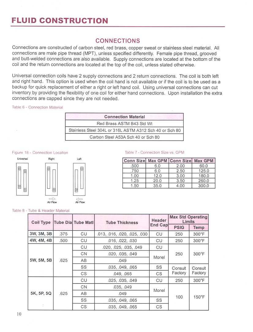
1 Fluid Coils Cooling applications are most commonly used in chilled fluid systems for comfort conditioning of a forced air stream and in process systems for dehumidification processes. A large variety of drainable circuiting options makes this a good choice for most general heat transfer applications. For use with water, glycols, brines, thermal oils or ammonia. Desaturation Coils TWO COILS IN ONE. A combination cooling/reheat coil in one common case that will both dehumidify the air and reheat that same air to the desired leaving air temperature and humidity level in low comfort cooling applications such as hospitals, clean rooms, and science or research laboratories. A single supply and return connection is used thus saving end users and installing contractors significant equipment, piping and labor costs. One coil is required thus saving the end user the cost of purchasing a second coil. Also, potential reduction in APD.WPD = Reduced Hp=Energy Savings = Bottom Line Dollar Savings Tubing Circuiting Rows Fin Surface Casing Connections Vents & Drains Hot Water Coils FLUID COIL CONSTRUCTION 3/8" or 1/2" O.D. Copper, 5/8" O.D. Copper, Cupronickel, Stainless Steel, Carbon Steel or Admiralty Brass Quarter, Half, Three Quarter, Single, One and one half, Double, Triple or Custom Quarter, Half, Three Quarter, Single, One and one half, Double, Triple or Custom Sine Wave (corrugated), New Ripple (peak and valley) or Flat Galvanized Steel, Stainless Steel, Carbon Steel, Copper or Aluminum Carbon Steel, Stainless Steel, Red Brass, or Copper Sweat (MPT, FPT, Victaulic, Grooved or Welded) Standard on all coils. Heating applications are most commonly used in hot fluid systems for comfort conditioning of a forced air stream and in process systems for drying processes. The collector header design with internal baffles provides circuiting flexibility while eliminating the need for return bends, while the splayed header design uses return bends for circuiting in lieu of a collection header. The term "splayed" means that the coil headers are offset outward from the coil tubes. The splayed header coil always has same end connections.
2 Cleanable Fluid Coils Cleanable applications are commonly used where mechanical cleaning of the coil tubes is required. One and two row coils are furnished with removable brass threaded plugs on either or both ends. Multirow coils utilize a removable steel head plate in lieu of coil headers. This plate contains baffles to provide coil circuitry and is removable for easy access to coil tubes. Cleanable options include cleanable from the supply connection end, cleanable from the end opposite the supply connection, or cleanable from both ends.
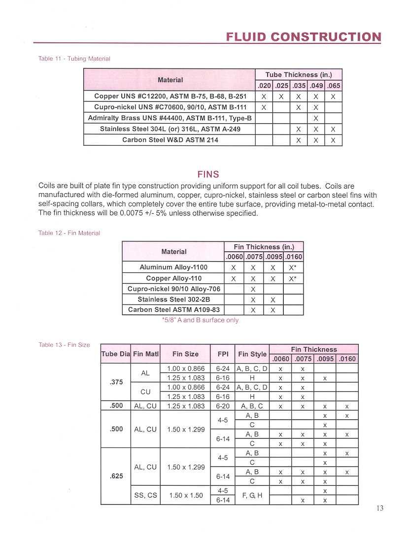
3 HEATCRAFT FLUID COIL SPECIFICATION 1.0 CERTIFICATION Acceptable coils are to have ARI Standard 410 certification and bear the ARI symbol. Coils exceeding the scope of the manufacturer's certification and/or the range of ARI's standard rating conditions will be considered provided the manufacturer is a current member of the ARI Air-Cooling and Air-Heating Coils certification program and the coils have been rated in accordance to ARI Standard 410. Manufacturer must be ISO 9002 certified. 1.1 FLUID COIL DESIGN PRESSURES AND TEMPERATURES Coils shall be designed to withstand 250 psi maximum operating pressures and a maximum fluid temperature of 300 F for standard duty copper tube coils. Optional high pressure construction will include cupronickel tubes and headers to increase maximum operating pressure to 350 psi and maximum operating temperature to 450 F. For cleanable coils with removable heads, coils shall be designed to withstand 100 psi maximum operating pressures and a maximum fluid temperature of 150 F. Higher limits are available, depending on coil construction and/or materials used. 1.2 FACTORY TESTING REQUIREMENTS Coils shall be submerged in water and tested with a minimum of 315 psi air pressure for standard copper tube coils and 125 psi for cleanable coils with removable heads. A 500 psig hydrostatic and shock test is required for high pressure cupronickel construction. Coils must display a tag with the inspector's identification as proof of testing. 1.3 FINS Coils shall be of plate fin type construction providing uniform support for all coil tubes. Stainless steel fins shall be constructed of 304 & 316 stainless. Carbon steel fins shall be constructed of ASTM A Coils are to be manufactured with die-formed aluminum, copper, stainless steel or carbon steel fins with self-spacing collars which completely cover the entire tube surface. The fin thickness shall be /- 5% unless otherwise specified. Manufacturer must be capable of providing self-spacing die-formed fins 4 through 14 fins/inch with a tolerance of +/- 4%. 1.4 TUBING Tubing and return bends shall be constructed from UNS seamless copper conforming to ASTM B75 and ASTM B251 for standard pressure applications. High pressure construction shall use seamless 90/10 Cupronickel alloy C70600 per ASTM B111. Stainless steel tubes shall be ASTM A249. Carbon steel tubes shall be W&D / ASTM A214 & seamless A179. Copper tube temper shall be light annealed with a maximum grain size of mm and a maximum hardness of Rockwell 65 on the 15T scale. Design permits in-tube water velocities up to 6 ft/s for the standard seamless copper tubing, and up to 8 ft/s for optional seamless alloy C70600 cupronickel tubing. Tubes are to be mechanically expanded to form an interference fit with the fin collars. Coil tube size and wall thickness' are 5/8"x0.020 and 1/2"x0.016 and 1"x.035 standard for copper, with other options available. Steel tubes are offered as 5/8"x0.035 or HEADERS Headers shall be constructed from UNS seamless copper conforming to ASTM B75 and ASTM B251 for standard pressure applications. High-pressure construction is to incorporate seamless 90/10 Cupronickel alloy C70600 per ASTM B111. Stainless steel will be constructed of 304L & 316L (ASTM-A240) Sch-5 or Sch-10. Carbon steel headers shall be constructed of Sch-10 (ASTM-A135A) or Sch-40 (ASTM A53A) pipe. Coil return headers are to be equipped with factory-installed 1/2 fpt air vent connection placed at the highest point available on face of the header. Tube-to-header holes are to be intruded inward such that the landed surface area is three times the core tube thickness to provide enhanced header to tube joint integrity. all core tubes shall evenly extend within the inside diameter of the header no more than 0.12 inch. End caps shall be die-formed and installed on the inside diameter of the header such that the landed surface area is three times the header wall thickness. 1.6 CONNECTIONS Standard construction fluid connections are male pipe thread (MPT) and constructed from red brass conforming to ASTM B43 or Schedule 40 steel pipe as a minimum. Stainless steel will be304l or 316L (ASTM-A240) Sch-40 or Sch 80. Carbon steel will be A53A Sch-40, A106A Sch-40 or Sch-80 or A53B Sch-80 pipe. Page 1 of 2
4 1.7 CLEANING All residual manufacturing oils and solid contaminants are removed internally and externally by completely submersing the coil in an environmentally and safety approved type degreasing solution, which is also chemically compatible with the coil material. This may vary for steel tube coils, depending on the application and/or customer specifications. 1.8 BRAZING Oxyfuel gas brazing, using fillet rod material of minimum 5% silver, is used for all non-ferrous tube joints to headers and connections. Depending on the application, ferrous to non-ferrous brazing material may contain upwards of 35% silver, or may be Tobin bronze WELDING Gas shielded arc welding is used for welded vessels constructed of stainless steel. Gas welding is used for welded vessels constructed of carbon steel. 1.9 CASING Coil casing and endplate shall be fabricated from Galvanized steel, as a standard construction, meeting ASTM and UL G90U requirements, Aluminum, thick, optional, Copper, thick, optional,16- or 14-gauge carbon steel or stainless steel, optional. double-flange casing shall be provided when coils are specified as vertical stacking. Standard coil intermediate tube sheets (center tube supports) shall be fabricated from the same gauge sheet stock and material as the end plates, and to the following schedule: Finned Length (inches) Number of Tube Sheets and greater CERTIFICATION Performance certified coils that are ARI Standard 410 listed bear the ARI symbol. Coils exceeding the scope of the certification and/or the range of standard rating conditions are also rated to the extent possible by the ARI Std. 410 method. Luvata continues as a current and active member of the ARI Air-Cooling and Air-Heating Coils certification program, with original coil line certification and computerized selections dating back to AGENCY APPROVAL Luvata Grenada LLC was facility registered by UL in 1994 to ISO 9002 (ANSI/ASQC Q92). Applicable commercial coil models are UL Standard 207 registered as Refrigerant Containing Components and Accessories; non-electrical. CRN, category H. Note: Luvata Grenada LLC can provide ASME code stamped vessels INSTALLATION Coils to be installed in accordance with manufacturer s instructions and any applicable piping codes LEAD TIME Standard lead-time for custom made retrofit fluid coils of standard construction with OEM circuiting shall be working days, with reduced lead-time emergency shipment options of 10 working days and 5 working days from order placement date and based upon production approval. Standard lead-time for custom made fluid coils of manufacturer s own standard design and circuiting shall be 10 working days, with reduced lead-time emergency shipment options for 5 working days, 48-hours and 24-hours from order placement date. All coils shall be quoted and offered as FOB Factory, Full Freight Allowed to any and all destinations within the Continental United States. Page 2 of 2
5 CERTIFIED DRAWING 1 & 2 ROW HOT WATER CP 1064-D Customer Job Written by Approved by Customer P.O. Number Date Date # TAG QTY TYPE FPI MODEL NUMBER ROWS FIN FH FL DEEP DIMENSIONAL DATA CONNECTION FLANGES # SIZE A B C E H I J L M R S T W MATERIALS OF CONSTRUCTION FINS AL CU CS St Stl TUBES CU CuNi CS St Stl HEADERS CU CuNi Carbon Stl St Stl CONN CS Red Brass Cu Sweat St Stl CASING AL Galvanized Steel CU Stainless Steel GENERAL OPTIONS Inverted Flanges End Plates Only Label Kit Mounting Holes Phenolic Coating Turbospirals REMARKS: CONN. & V/D OPTIONS End Cap Tee Side 0.50 FPT Cpl. FPT Connections End Cap Side 1. Coils will vent and drain through factory-installed vent and drain fittings when mounted level for horizontal flow. 2. If S < 1 or End Plates Only Case, vents and drains will be located on the side of the header. Connection locations other than standard could affect vent and drain locations. Consult factory. 3. Mounting holes are optional diameter holes on 6 centers from the centerline of the fin height and finned length are typical for all flanges. Not available with Inverted Flanges or when S< All dimensions are in inches. 5. Type K coils have removable plugs on both ends. GENERAL NOTES 6. Type P coils have removable plugs on connection end only. 7. Type Q coils have removable plugs on opposite connection end only. 8. With Inverted Flanges or End Plates Only construction, headers will extend a maximum of above and below the casing. Vents and drains will be located on the side of the headers. 9. Intermediate tube supports are fabricated from heavy gauge stock and supplied per the chart below. Finned Length (FL) < 48 > 48 < 96 > 96 < 144 > 144 Tube Supports
6 CERTIFIED DRAWING FLUID CP 1063-D Customer Job Written by Approved by Customer P.O. Number Date Date # TAG QTY TYPE FPI MODEL NUMBER ROWS FIN FH FL DEEP HAND Left, Right Universal DIMENSIONAL DATA CONNECTION FLANGES # SIZE A B C D E F H I J L M R S T W MATERIALS OF CONSTRUCTION FINS AL CU CS St Stl TUBES CU CuNi CS St Stl HEADERS Cu CuNi Carbon Stl CONN St Stl CS Red Brass Cu Sweat St Stl CASING AL Galvanized Steel CU Stainless Steel GENERAL OPTIONS Inverted Flanges End Plates Only Label Kit Mounting Holes Phenolic Coating Turbospirals REMARKS: CONN. & V/D OPTIONS End Cap Tee Face 0.50 FPT Cpl. Face 0.25 Tee Face 0.50 MPT 7 Ext. Side 0.50 FPT FPT Connections End Cap Face Side GENERAL NOTES 1. Coils will vent and drain through factory-installed vent and drain fittings when mounted level for horizontal flow. 2. If S < 1 or End Plates Only Case, vents and drains will be located on the face or side of the header. Connection locations other than standard could affect vent and drain locations. Consult factory. 3. Mounting holes are optional diameter holes on 6 centers from the centerline of the fin height and finned length are typical for all flanges. Not available with Inverted Flanges or when S < All dimensions are in inches and 2 serpentine 3, 4 and 5-row coils. 3 serpentine 6-row, and 5M (splayed header) coils are available only as left- or right-handed serpentine 3- and 5-row coils, 2 serpentine 6- and 10-row coils, and 9-row coils have supply and return connections on opposite ends. All other serpentine and row configurations have same end connections. 7. The supply line should be connected to the lower connection on the leaving air side for counterflow operation. 8. With Inverted Flanges or End Plates Only Case construction, headers will extend a maximum of above and below the casing. Vents and drains will be located on the face of the headers. 9. Intermediate tube supports are fabricated from heavy gauge stock and supplied per the chart below. Finned Length (FL) < 48 > 48 < 96 > 96 < 144 > 144 Tube Supports
7 CERTIFIED DRAWING DESATURATION CP 1197-B Customer Job Written by Approved by Customer P.O. Number Date Date TAG QTY MODEL NUMBER HAND (Left or Right) PATENT PENDING DIMENSIONAL DATA CONNECTION FLANGES SIZE A B C E H I J L M N R S T W MATERIALS OF CONSTRUCTION FINS 1 AL CU FINS 2 AL CU TUBES CU CuNi Adm Brass HEADERS CU CuNi Carbon Stl CONN CS Red Brass Cu Sweat CASING AL Galvanized Steel CU Stainless Steel GENERAL OPTIONS Inverted Flanges End Plates Only Label Kit Mounting Holes Corrosion Resistant Coating Turbospirals REMARKS: CONN. & V/D OPTIONS End Cap Tee Face 0.50 FPT Cpl. Face 0.25 Tee Face 0.50 MPT 7 Ext. Side 0.50 FPT FPT Connections End Cap Face Side GENERAL NOTES 1. All dimensions are in inches. 2. Coils will vent and drain through factory-installed vent and drain fittings when mounted level for horizontal flow. 3. If S < 1 or End Plates Only Case, vents and drains will be located on the face or side of the header. Connection locations other than standard could affect vent and drain locations. Consult factory. 4. Mounting holes are optional diameter holes on 6 centers from the centerline of the fin height and finned length are typical for all flanges. Not available with Inverted Flanges or when S < The supply line should be connected to the lower connection on the entering air side for counterflow operation. 6. With Inverted Flanges or End Plates Only Case construction, headers will extend a maximum of above and below the casing. Vents and drains will be located on the face of the headers. 7. Intermediate tube supports are fabricated from heavy gauge stock and supplied per the chart below. Finned Length (FL) < 48 > 48 < 96 > 96 < 144 > 144 Tube Supports
8 CERTIFIED DRAWING CLEANABLE FLUID CP 1070-D Customer Job Written by Approved by Customer P.O. Number Date Date # TAG QTY TYPE FPI MODEL NUMBER ROWS FIN FH FL DEEP HAND Left Right DIMENSIONAL DATA CONNECTION FLANGES # SIZE A E H J L M R S T W FIG# GENERAL OPTIONS Label Kit Mounting Holes Phenolic Coating MATERIALS OF CONSTRUCTION FINS AL CU CS St Stl Fin Thick TUBES CU CuNi CS St Stl Tube Size HEADERS CU CuNi CS St Stl CONN CS Cu Sweat Red Brass St Stl CASING AL CU Galv Stl St Stl KH, KS, KD Cleanable Both Ends A E E REMARKS: General Notes 2 8. KH return 9. KS, 4& 8 Row KD return Row KD return 2 H FL FH 2 8 SUPPLY CONN. 2 E E Figure 2 PS, PD Cleanable Supply End General Notes 8. Return connection 9. 6 Row PD return Figure 3 QH, QS, QD Cleanable Opposite Supply End 2 General Notes 8. QH return 9. QS, 4& 8 Row QD return Row QD return DRAINS 9 A E E H J H M T T T FL L FH W 10 J S J A 9 DRAINS A 2 L FH L S S S FL S R R R J M E 2 E A A DRAINS 8 A DRAINS W 8 A A VENTS SUPPLY CONN. E 2 SUPPLY CONN. E * * A or on 4 row QD only GENERAL NOTES 1. Mounting holes are optional diameter holes on 6 centers from the centerline of the fin height and finned length are typical for all flanges. Not available when S < Jackscrews are provided to facilitate head removal. 3. All dimensions are in inches. 4. The supply line should be connected to the lower connection on the leaving air side for counterflow operation wide reinforcement bars may extend past flanges. 6. Phenolic coated coils require a longer lead-time since they must be re-tested after coating. 7. Intermediate tube supports are fabricated from heavy gauge stock and supplied per the chart to the below. Finned Length (FL) Tube Supports < 48 0 > 48 < 96 1 >96 < > 144 4

9 Fluid Coil Installation Operation and Maintenance LUVATA GRENADA LLC PO Box 1457 / 1000 Heatcraft Drive, Grenada, MS Tel: / Fax: coils@luvata.com Web Site:
10
11 FLUID IOM Guidelines for the installation, operation and maintenance of Heatcraft cooling and heating coils have been provided to help insure the proper performance of the coils and their longevity. These are general guidelines that may have to be tailored to meet the specific requirements of any one job. As always, the installation and maintenance of any coil should be performed by a qualified party or individual. Protective equipment such as safety glasses, steel toe boots and gloves are recommended during the installation and routine maintenance of the coil. Receiving Instructions 1. All Heatcraft coils are factory tested, inspected and carefully packaged. 2. Damage to the coils can occur after they have left the factory. Therefore, the coils should be inspected for shipping damage upon receipt. The freight bill should also be checked against items received for complete delivery. 3. Damaged and/or missing items should be noted on the carrier s freight bill and signed by the driver. 4. For additional assistance, contact your local Heatcraft coil representative. Nomenclature 5 W S C x Tube O.D. Finned Length (inches) 3=3/8 4=1/2 Fin Height (inches) 5=5/8 Coil Type Fin Design W Standard Water A - flat (Al, Cu) M Splayed Headers B - corrugated (Al, Cu) B Booster C - sine wave (Al, Cu) K Cleanable Both Ends F - flat (SS, CS) P Cleanable Supply End G - corrugated (SS, CS) Q Cleanable Opp. Supply End H - sine wave (SS, CS, Al, Cu) Circuiting Rows Deep Q - 1/4 serp M - 1 1/2 serp H - 1/2 serp D - 2 serp L - 3/4 serp T - 3 serp Fins Per Inch S - 1 serp B - skip tube Booster S - 1 circuit B - skip tube D - 2 circuits 1
12 FLUID IOM Mounting 1. All Heatcraft water and glycol coils are designed to be fully drainable when properly mounted. 2. Vertical air-flow is not recommended for dehumidifying coils. Coil Types Standard Fluid Coils Heatcraft fluid coils are specifically designed for your particular application. Flexibility is built into our manufacturing processes, offering variations in fin type, fin density, circuitry arrangement, coil casing and materials of construction. Standard fluid type W coils utilize a collection header for one and two row applications and return bends for applications that require three or more rows. Type M coils are used for one and two row applications that require same end connections. For type M coils the supply and return headers are offset or splayed. This orientation allows for the supply and return headers to be placed side by side. Booster coils, type B, are also available for one and two row applications. 2

13 FLUID IOM Cleanable Fluid Coils We offer cleanable fluid coils for applications where mechanical cleaning of the internal surface of the tubes are required. Our cleanable coils utilize a box-style head in lieu of cylindrical headers. The head contains baffles for circuiting and is removable for easy access to coil tubes. Type P coils are cleanable from the supply end of the coil. Type Q coils are cleanable from the end opposite the supply. Type K coils are cleanable from both ends of the coil. Installation 1. Carefully remove the coil from the shipping package to avoid damage to the finned surface area. Damaged fins can be straightened using an appropriate fin comb. If a mist eliminator was purchased, remove it before installation. 2. For coils with removable heads, check the torque on the nuts before installing. Refer to Maintenance on Page 6 for recommended torque values. 3. Heatcraft recommends cleaning the coil with a commercially available coil cleaner prior to installation. Refer to Maintenance on Page 6 for cleaning recommendations. 4. Check the coil hand designation to insure that it matches the system. Water and glycol coils are generally plumbed with the supply connection located on the bottom of the leaving air-side of the coil and the return connection at the top of the entering air-side of the coil (Figure 2 - Connection Diagram). This arrangement provides counter flow heat exchange and positive coil drainage. If a universal coil is supplied, cap off the two unused connections. 5. Standard coils must be mounted level to insure drainability. Refer to Mounting on page 2 for leveling requirements. Coils with intermediate headers and coils with removable box style headers can be pitched 1/8 per foot of coil finned length towards the coil s header/connection end. 6. Proper clearance should be maintained between the coil and other structures such as the fan, filter racks, transition areas, etc.. 7. Once installed, the coil should be pressurized to 100 psig with dry nitrogen or other suitable gas. The coil should be left pressurized for a minimum of 10 minutes. If the coil holds the pressure, the hook-up can be considered leak free. If the pressure drops by 5 psig or less re-pressurize the coil and wait another 10 minutes. If the pressure drops again, there is more than likely one or 3
.")
14 FLUID IOM more small leaks which should be located and repaired. Pressure losses greater than 5 psig would indicate a larger leak that should be isolated and repaired. If the coil itself is found to be leaking, contact your local Heatcraft coil representative. Unauthorized repair to the coil may void the coil s warranty (see Luvata s warranty policy on back cover). 8. All field brazing and welding should be performed using high quality materials and an inert gas purge (such as nitrogen) to reduce oxidation of the internal surface of the coil. 9. All field piping must be self supporting. System piping should be flexible enough to allow for thermal expansion and contraction of the coil. 10. General piping diagrams can be found in Figure 1 - Horizontal Airflow and Figure 3 - Vertical Airflow. 11. (If a mist eliminator was purchased) With the coil installed, place the mist eliminator into its brackets. Make sure the mesh is aligned with the coil face area (finned area). Figure 1 - Horizontal Airflow Diagram 4 Figure 2 - Coil Diagram


15 FLUID IOM Figure 3 - Vertical Airflow Diagram Figure 4 - Mist Eliminator Installation Operation Initial Start-Up 1. Open all air vents so that air is eliminated from within the coil circuitry and headers. Verify that all vents and drains are not obstructed and do discharge a stream of water. 2. Fill the coil with water then close all vents. 3. Perform an initial hydrostatic leak test of all brazed, threaded or flanged joints, valves and interconnecting piping. Recheck the coil level and correct if necessary. When the setup is found to be leak free, discharge and discard initial water charge. It is important that all grease, oil, flux and sealing compounds present from the installation be removed. 5
16 FLUID IOM General 1. Proper air distribution is vital to coil performance. Air flow anywhere on the coil face should not vary by more than 20%. 2. The drain pan and associated piping (drain line and trap) should be installed so that there is no standing water in the drain pan and that no blow-through occurs. 3. Fluid and air velocities should be maintained within our recommended values. Table 2a Table 2b Fluid Velocity Water 1 to 8 fps Glycol 1 to 6 fps Maintenance 6 General 1. Filters and mist eliminators should be inspected on a regular basis and changed as needed. Maintaining clean filters and mist eliminators is a cost effective way to help maintain maximum coil performance and service life. 2. Periodic inspection of the coil for signs of corrosion and/or leaks is recommended. Repair and replacement of the coil and the connecting piping, valves, etc., should be performed as needed by a qualified individual(s). 3. Should the coil surface need cleaning, caution should be exercised in selecting the cleaning solution as well as the cleaning equipment. Improper selection can result in damage to the coil and/or health hazards. Clean the coil from the leaving air-side so that foreign material will be washed out of the coil rather than pushed further in. Be sure to carefully read and follow the manufacturer s recommendations before using any cleaning fluid. 4. Maintain the circulated fluid free of sediment, corrosive products and biological contaminants. Periodic testing of the fluid followed by any necessary corrective measures along with maintaining adequate fluid velocities and proper filtering of the fluid will help to satisfy this goal. 5. If automatic air vents are not utilized, periodic venting of the coil is recommended to remove accumulated air. Caution should be exercised to avoid injury. High pressure and/or high temperature fluids can cause serious personal injury. 6. Heatcraft s cleanable coils with removable box headers should be cleaned using a suitable brush or its equivalent. Dislodged debris should be flushed from the coil and drain pan. Be sure that debris does not clog the drain. After the coil has been cleaned, the old gaskets should be discarded and replaced with new ones (contact your local Heatcraft coil representative for replacement gaskets). The box header should then be reinstalled. The recommended instal-
17 FLUID IOM lation procedure is as follows. a. Nuts and weld studs should be coated with thread lubricant. b. Tighten all nuts per Figure 5 - Torque Pattern, to 35 ft-lb torque. After the initial torque has been applied retorque them to 50 ft-lb, again using the pattern shown in Figure 5. The permissible range of final torque values are as follows: maximum torque: design torque: minimum torque: c. Pressure test coils per the installation instructions. 53 ft-lb 50 ft-lb 47 ft-lb d. After the coil has been leak tested and found to be free from leaks, let it sit for 24 hours. Retorque to 50 ft-lb per Figure 5 - Torque Pattern. e. Refill the coil per the operation instructions. Figure 5 - Torque Pattern Freeze Protection During the winter, chilled water coils need to be protected against freezing. The two predominant protective measures are covered below. Blowing-Out Coils 1. Isolate the coil from the rest of the system by closing the valves on both the supply and return lines (gate valves in Figure 1 - Horizontal Airflow and Figure 3 - Vertical Airflow). 2. Drain the coil by opening all drain valves and/or the drain plug. Remove the vent plug to aid the draining process. 3. Once the coil has been fully drained, the blower can be hooked-up. Caps installed in the piping on straight runs going to the supply and return connections are ideal points to hook-up the blower. The air vent and drain plug are not suitable locations for hookingup the blower. Caution should be exercised when installing the blower. The blower operator must take precautions to insure that water does not come into contact with any 7
18 FLUID IOM of the electrical components of the blower. Failure to do so may result in damage to the equipment and serious injury. 4. Close the vent or drain plug on the header which the blower is connected and open the drain valve or cap on the other header. 5. Operate the blower for 45 minutes and then check the coil to see if it is dry. A mirror placed in the discharge will become fogged if moisture is present. Repeat this procedure until the coil is dry. 6. Let the coil stand for several minutes then blow it out again. If water comes out, repeat the blowing operation. 7. Leave all plugs out and drains open until the threat of freezing has passed. Flushing Coils 1. We recommend the use of inhibited glycol designed for HVAC applications for corrosion protection. The use of uninhibited glycol has produced formicary corrosion in copper tubing. The complete filling of water coils with an inhibited glycol solution for freeze protection can be expensive. In some instances, it is more cost effective to flush the coils with an appropriate concentration of inhibited glycol solution. Residual fluid can be left in the coil without the threat of freeze damage provided the correct concentration of inhibited glycol was used. The recovered fluid can then be used to flush other coils. Select an inhibited glycol solution that will protect the coil from the lowest possible temperatures that can occur at the particular coil s locality. The following tables have been provided for your convenience. 1 Freeze points may vary from product to product Estimate the volume of the coil in gallons. For 5/8 tubes (1.5 face tube spacing) (finned height in inches)x(finned length in inches)x(# of rows)x = gallons For ½ tubes (1.25 face tube spacing) (finned height in inches)x(finned length in inches)x(# of rows)x = gallons 3. Isolate the coil from the rest of the system by closing the valves on both the supply and return lines (gate valves in Figure 1 - Horizontal Airflow and Figure 3 - Vertical Airflow).
19 FLUID IOM 4. Drain the coil by opening all drain valves and/or the drain plug. Remove the vent plug to aid the draining process. 5. Close the drain valve(s) and drain plug. 6. Connect the flushing system to the coil. A typical system is shown in Figure 6 - Flushing System Diagram. 7. With the throttling valve closed, start the pump and operate until the air is vented from the coil. Next, close the air vent. 8. Open the throttling valve about half-way and circulate the fluid through the coil for 15 minutes. Check the strength of the fluid. A hydrometer or test kit from the fluid manufacturer is suitable for this application. 9. Adjust the solution strength as needed and circulate the fluid for another 15 minutes. 10. Repeat steps 8 and 9 until the desired concentration is reached. 11. Shut the pump down and drain the inhibited glycol from the coil. 12. The recaptured fluid can be used to flush other coils. Note: Be sure to follow the manufactures recommendations before utilizing any glycol based antifreeze solution. Additional fluid will be required for the pump, connected piping and fluid reservoir. Formulae are for estimation purposes only. Figure 6 - Flushing System Diagram 9
20 COMMERCIAL PRODUCTS WARRANTY Luvata Grenada LLC, hereinafter referred to as the Company, warrants that it will provide free suitable repair or replacement of coils in the event any coil of its manufacture used in the United States proves defective in material or workmanship within twelve (12) months from the date shipped by the Company. THIS WARRANTY CONSTITUTES THE BUYER S SOLE REMEDY. IT IS GIVEN IN LIEU OF ALL OTHER WARRANTIES. THERE IS NO IMPLIED WARRANTY OF MERCHANTABILITY OR FITNESS FOR A PAR- TICULAR PURPOSE. IN NO EVENT AND UNDER NO CIRCUMSTANCE SHALL THE COMPANY BE LIABLE FOR INCIDENTAL OR CONSEQUENTIAL DAMAGES, WHETHER THE THEORY BE BREACH OF THIS OR ANY OTHER WARRANTY, NEGLIGENCE, OR STRICT TORT. This warranty extends only to the original purchaser. Of course, abuse, misuse, or alteration of the product in any manner voids the Company s warranty obligation. This warranty does not obligate the Company to pay any labor or service costs for removing or replacing parts, or any shipping charges. No person (including any agent or salesman) has authority to expand the Company s obligation beyond the terms of this express warranty, or to state that the performance of the coil is other than that published by Luvata Grenada LLC. LUVATA GRENADA LLC PO Box 1457 / 1000 Heatcraft Drive, Grenada, MS Tel: / Fax: coils@luvata.com Printed in U.S.A. June 2006

21 FLUID COILS
22
23
24
25
26
27
28
29
30
31
32 FLUID CONSTRUCTION COIL CASE Casings and endplates are made from 16 gauge-galvanized steel unless otherwise noted. Doubleflanged casings on top and bottom of finned height are to be provided, when possible, to allow stacking of the coils. All sheet metal brakes shall be bent to 90 degrees +/- 2 degrees otherwise. Coils shall be constructed with intermediate tube support sheets fabricated from a heavy gauge sheet stock of the same material as the case, when possible. Figure 20 - Coil Case Table 9 - Coil Case Material Material Gauge Galvanized Steel, ASTM A-924 and A-653 X X X Copper ASTM B-152 X X X Aluminum Alloy-3003, Embossed Finish Alloy-5052, Mill Finish (.125 only) X X X Stainless Steel 304L (or) 316L, 2B-Finish, ASTM A-240 X X * X Stainless Steel 201L X X *Not available in pierce and flare header plates Table 10 - Tube Supports TUBE SUPPORTS Quantity F inned Length (FL) < 48 > 48 < 96 > 96 < 144 > 144 Tube Supports TUBING Tubing and return bends are be constructed from seamless copper, cupro-nickel, admiralty brass, stainless steel or carbon steel tubing. Copper tube temper are light annealed with a maximum grain size of mm and a maximum hardness of Rockwell 65 on the 15T scale. Tubes are mechanically expanded to form an interference fit with the fin collars. Tubes will have a nominal thickness of inch unless otherwise specified. 12
33
34
35

36
37
38
39
40

41
42 Luvata Grenada LLC Commercial Products PO Box 1457 / 1000 Heatcraft Drive, Grenada, MS Tel: / Fax: s: coils@luvata.com Web: June 2006 Printed in the USA
Fluid Coils. Desaturation Coils. Hot Water Coils
 Fluid Coils Cooling applications are most commonly used in chilled fluid systems for comfort conditioning of a forced air stream and in process systems for dehumidification processes. A large variety of
Fluid Coil Installation, Operation and Maintenance
 Bulletin FCO&I 001 REV A Fluid Coil Installation, Operation and Maintenance Monika Hewlett Packard Company [Pick the date] FLUID COIL INSTALLATION, OPERATION & MAINTENANCE GUIDELINES Fluid Coil Installation,
Nomenclature. Nomenclature Distributing coil types
 STEAM COILS Contents and Nomenclature Distributing coil types Nomenclature... 1 Distributing Coil Types JA and GA... 1 DA and LA... 1 RA and TA... 2 Non-Distributing Coil Types SA and HA, SB and HB...
Steam Coils. Connections. Vents & Drains. Standard on all coils
 Steam Coils Standard or steam distributing construction is available for high and low pressure applications. Standard steam type is the basic 5/8" or 1" tube steam coil, known as the single tube design.
Daikin Steam Coils. Installation and Maintenance Manual IM 901. Types HI-F5, HI-F8, & E-F5. Group: Applied Air. Part Number: IM 901
 Installation and Maintenance Manual IM 901 Daikin Steam Coils Group: Applied Air Part Number: IM 901 Date: February 2008 Types HI-F5, HI-F8, & E-F5 2008 Daikin Applied Contents Introduction... 3 General
Contents and Nomenclature
 Fluid Coils Contents and Nomenclature Nomenclature... Standard Fluid Coils... -3 Modu-coil Option... 3 Booster Coils... 3 Cleanable Coils... 4-5 Fluid Construction Connections... 6 Tube & Header Material...
Complete HVAC Capability
 Air Handling Units Brochure 1110 January 2006 Complete HVAC Capability MEA Horizontal Draw-Thru to Size 65 Vertical Draw-Thru to Size 50 1000 to 60,000 CFM Forward Curved or Airfoil Wheels Inlet Vane Option
Margaret M. Alkek Building for Biomedical Research Baylor College of Medicine. Appendix A Runaround Loop Component Information
 Justin Mulhollan Spring 06 Mechanical Option Margaret M. Alkek Building for Biomedical Research Baylor College of Medicine Houston, TX Appendix A Runaround Loop Component Information 47 Pump Data Sheet
Hand Expansion Valves Built Stronger to Last Longer Sizes: 6mm (¼ ) to 305mm (4 )
 to 305mm (4 )") Hand Expansion Valves Built Stronger to Last Longer Sizes: 6mm (¼ ) to 305mm (4 ) Bulletin No. 82-00A Suitable For: Ammonia, Fluorocarbons, Nitrogen and Carbon Dioxide Features ASTM 352 LCB Cast Steel
Hand Expansion Valves Built Stronger to Last Longer Sizes: 6mm (¼ ) to 305mm (4 ) Bulletin No. 82-00A Suitable For: Ammonia, Fluorocarbons, Nitrogen and Carbon Dioxide Features ASTM 352 LCB Cast Steel
SBH / SBV Sales Guide BLOWER-COILS HORIZONTAL AND VERTICAL
 SO TOUGH, WE GUARANTEE IT. SBH / SBV Sales Guide BLOWER-COILS HORIZONTAL AND VERTICAL SBH SBV www.superiorrex.com SO TOUGH, WE GUARANTEE IT! www.superiorrex.com SBH / SBV Series: CONSTRUCTION FEATURES
Grinnell Grooved Fire Protection Products Grooved Fittings
 Technical Services: Tel: (800) 38-932 / Fax: (800) 79-5500 www.tyco-fire.com Grinnell Grooved Fire Protection Products Grooved Fittings General Description LPCB Vd S The grooved fittings provide an economical
APCO CRF-100A RUBBER FLAPPER SWING CHECK VALVES
 APCO CRF-100A RUBBER FLAPPER SWING CHECK VALVES Instruction D12043 June 2016 DeZURIK Instructions These instructions provide installation, operation and maintenance information for APCO CRF-100A Rubber
A Division of Nailor International Inc. ECONOMY AIR HANDLERS
 A Division of Nailor International Inc. MODEL : ECONOMY AIR HANDLERS Thermal Model Standard Specification MODEL 800-4000 CFM AIR HANDLERS Description Model air handlers are designed for efficient and economical
GARDEN HOSE UTILITY PUMP
 GARDEN HOSE UTILITY PUMP MODEL #HPP360, HPP12V, 473707 MODEL #HPP360, 473707 MODEL #HPP12V ATTACH YOUR RECEIPT HERE Purchase Date SAFETY INFORMATION Please read and understand this entire manual before
Manufacturing Facility is ISO9001:2000. Welded Steel Pipe Conform to ASTM A53. Threads Conform to ASME B1.20.1
 STEEL NIPPLES S40 & S80 Steel Nipple Product Specifications Manufacturing Facility is ISO9001:2000 Welded Steel Pipe Conform to ASTM A53 Threads Conform to ASME B1.20.1 800-678-2544 800-678-0857 www.msi-products.com
TERMS OF USE TERMS AND CONDITIONS. Plumbing and Heating Products (PL-WR)
") TERMS OF USE 1. Watts pricing and product data is subject to change without notice and such changes supersede all previous versions. 2. Watts data is to be used as provided. Watts is not responsible for
TERMS OF USE 1. Watts pricing and product data is subject to change without notice and such changes supersede all previous versions. 2. Watts data is to be used as provided. Watts is not responsible for
APCO ASR-400/450 SEWAGE AIR RELEASE VALVES
 APCO ASR-400/450 SEWAGE AIR RELEASE VALVES Instruction D12005 December 2012 Instructions These instructions provide installation, operation and maintenance information for the APCO ASR- 400/450 Sewage
Series 3500 Externally Pressurized Expansion Joints Catalog 574 H
 Series 3500 Externally Pressurized Expansion Joints Catalog 57 H 500 Laminated Bellows Expansion J Series 3500 on Joints Externally Pressurized Expansion Joints Standard Designs Sizes " through ", 50 &
V400D VERIS Verabar (Double Rod) Installation and Maintenance Manual
 Installation and Maintenance Manual") V400D VERIS Verabar (Double Rod) Installation and Maintenance Manual 168-EN Please read and save these instructions Contents General Safety Information...3 Product Information...3 Section 1: Scope...3
V400D VERIS Verabar (Double Rod) Installation and Maintenance Manual 168-EN Please read and save these instructions Contents General Safety Information...3 Product Information...3 Section 1: Scope...3
BC Series Multi-position Air Handler Engineering and Specification Guide (Electric and Water Heat)
") BCAHSG-2 3-Jun BC Series Multi-position Air Handler Engineering and Specification Guide (Electric and Water Heat) 5 YEAR WARRANTY see warranty form for details Contents: Page Number Product Features 2
BCAHSG-2 3-Jun BC Series Multi-position Air Handler Engineering and Specification Guide (Electric and Water Heat) 5 YEAR WARRANTY see warranty form for details Contents: Page Number Product Features 2
Installation Manual DIAPHRAGM WELL TANK
 Installation Manual DIAPHRAGM WELL TANK IN-LINE SERIES: 2-5 & 7 GALLON VERTICAL SERIES: 14-20-25-32-36-52-65-86-96-119 GALLON HORIZONTAL SERIES: 7-14 & 20 GALLON NO LEAD NO LEAD: The weighted average of
FAN POWERED HEPA FILTER UNIT
 READ COMPLETELY AND SAVE THESE INSTRUCTIONS FOR FUTURE REFERENCE FAN POWERED HEPA FILTER UNIT (MOTOR ACCESSIBLE) SSLFHFD-FP-MA INSTALLATION AND SERVICE MANUAL 2 Critical operation conditions of the Fan
DeZURIK 2 20" BOS BUTTERFLY VALVES
 2 20" BOS BUTTERFLY VALVES Instruction D10459 October 2013 2-20 BOS Butterfly Valves Instructions These instructions provide information about BOS Butterfly Valves. They are for use by personnel who are
Air Curtain. Installation, Operating and Maintenance Instructions
 Installation, Operating and Maintenance Instructions Save this manual for future reference. Air Curtain Model Numbers: ES026, ES036, ES042, ES048, ES060, ES072 READ THIS OWNER S MANUAL CAREFULLY BEFORE
DRAIN WATER TEMPERING KIT
 INSTALLATION, OPERATION AND MAINTENANCE MANUAL FOR FOR USE WITH SH(X) GAS FIRED HUMIDIFIER OUTDOOR MODELS CANADIAN HEAD OFFICE AND FACTORY 1401 HASTINGS CRES. SE CALGARY, ALBERTA T2G 4C8 Ph: (403) 287
SAMPLE COOLER and SLUDGE TRAP OPERATION & MAINTENANCE MANUAL
 SAMPLE COOLER and SLUDGE TRAP OPERATION & MAINTENANCE MANUAL PLEASE RECORD THE FOLLOWING DATA (Information is located on the product label or packing slip) Product: Model No: Serial No: Installation Date:
INTRODUCTION INSTALLATION
 INTRODUCTION INSTALLATION, OPERATION & MAINTENANCE INSTRUCTIONS This instruction manual includes installation, operation and maintenance information for the figure G73 gear operator. The figure G73 is
Operating and Installation Instructions
 Model Number 20902 Fabricator's Power Module Kit - Aluminum Operating and Installation Instructions CAUTION! This product is to be installed only by persons knowledgeable in the repair and modification
Carbon Steel Nipples
 CORPORATE OFFICE TEL (800) 766-0076 LOCAL (323) 890-4455 WWW.SMITHCOOPER.COM FAX (323) 890-4456 Carbon Steel Nipples Schedule 40 & 80 Welded, Schedule 80 Seamless, & XXH Seamless Carbon Steel Nipples Specifications
QUICK START GUIDE OWNER S MANUAL AL50 SERIES SAND FILTRATION TECHNOLOGY PLEASE CALL DO NOT RETURN TO STORE
 QUICK START GUIDE OWNER S MANUAL SAFETY, INSTALLATION, OPERATION & PARTS AL50 SERIES SAND FILTRATION TECHNOLOGY PLEASE CALL 877-278-2797 DO NOT RETURN TO STORE! WARNING This equipment must be installed
MEX (55) QRO (442) Web Controls
 QRO (442) Web Controls") Web Controls SINGLE AND DUAL ROTOR TENSION CONTROL BRAKES MODELS:,,,, AND INSTALLATION, OPERATION, AND MAINTENANCE INSTRUCTIONS Read this manual carefully, making full use of its explanations and instructions.
Web Controls SINGLE AND DUAL ROTOR TENSION CONTROL BRAKES MODELS:,,,, AND INSTALLATION, OPERATION, AND MAINTENANCE INSTRUCTIONS Read this manual carefully, making full use of its explanations and instructions.
PRYCO, INC. P. O. BOX 108 Mechanicsburg, IL OPERATIONS AND MAINTENANCE MANUAL For PUMP SETS
 PRYCO, INC. P. O. BOX 108 Mechanicsburg, IL 62545 Telephone: 217 / 364-4467 Fax: 217 / 364-4494 OPERATIONS AND MAINTENANCE MANUAL For PUMP SETS WHAT TO DO FIRST Upon receiving your new pump set system
Manual Transfer Switch
 Manual Transfer Switch Instruction Manual 30 1200 Amp 2, 3 & 4 Pole Page 1 WARNING Before Installation READ THIS MANUAL carefully to learn how to properly install, operate and maintain this unit. Personal
#7 Stock Cabinet Fan/Coils
 #7 Stock Cabinet Fan/Coils thru 1--USA-COIL (1--872-45) FAX: (610) 296-9763 www.usacoil.com TABLE OF CONTENTS Section Description Page No. Descriptive Information Horizontal Fan Coils Vertical Fan Coils
Operators Manual. Recirculating Chiller /06/08
 Operators Manual Recirculating Chiller 110-197 11/06/08 Table of Contents Section 1. General Information 1.1 Warranty 1.2 Unpacking 1.3 Package Contents 1.4 Description of the Recirculating Chiller 1.5
INDUSTRIES AMERICAN COOLAIR CORPORATION. Centrifugal Filtered Supply Roof Ventilators TYPE CFS - TYPE SIS
 INDUSTRIES AMERICAN COOLAIR CORPORATION Centrifugal Filtered Supply Roof Ventilators TYPE CFS - TYPE SIS CFS Centrifugal Filtered Supply Fans Applications The CFS Centrifugal Filtered supply fans with
PHANTOM (PH10 and PH12) COMMERCIAL AND INDUSTRIAL SERIES
 COMMERCIAL AND INDUSTRIAL SERIES") Document No: ICM-IOM Date: 0411 PHANTOM (PH10 and PH12) COMMERCIAL AND INDUSTRIAL SERIES Installation, Operation and Maintenance Manual Please read and save these instructions. Read carefully before attempting
Document No: ICM-IOM Date: 0411 PHANTOM (PH10 and PH12) COMMERCIAL AND INDUSTRIAL SERIES Installation, Operation and Maintenance Manual Please read and save these instructions. Read carefully before attempting
Rectangular Door L-VAT with pneumatic actuator double acting
 Rectangular Door L-VAT with pneumatic actuator double acting This manual is valid for the products: 0 7 5 1 0 U A 2 4 0 0 0 1 4 character option code Size 10... 46 x 236 12... 50 x 336 Actuator 24... without
DIFFERENTIAL PRESSURE RELIEF REGULATOR TYPE A4AL Port Size 3/4"- 4" (20-100mm) For Ammonia, R-22, R134a, R404a, R507 and other common refrigerants.
 For Ammonia, R-22, R134a, R404a, R507 and other common refrigerants.") DIFFERENTIAL PRESSURE RELIEF REGULATOR TYPE A4AL Port Size 3/4"- 4" (20-100mm) For Ammonia, R-22, R134a, R404a, R507 and other common refrigerants. FEATURES Pilot operated characterized Modulating Plug
DIFFERENTIAL PRESSURE RELIEF REGULATOR TYPE A4AL Port Size 3/4"- 4" (20-100mm) For Ammonia, R-22, R134a, R404a, R507 and other common refrigerants. FEATURES Pilot operated characterized Modulating Plug
42CET/ 42CED Series Chilled Water Fan Coil Unit Furred-in Ceiling Model 300 to 1400 cfm Electric heater option
 42CET/ 42CED Series Chilled Water Fan Coil Unit Furred-in Ceiling Model 0 to 10 cfm Electric heater option 42DC/ 42DCD Series Chilled Water Fan Coil Unit Furred-in Ceiling Model 0 to 00 cfm Electric heater
DeZURIK KUL KNIFE GATE VALVES
 KUL KNIFE GATE VALVES Instruction D11025 September 2013 Instructions These instructions are intended for personnel who are responsible for the installation, operation and maintenance of your KUL knife
GA Industries, LLC 9025 Marshall Road Cranberry Township, PA USA Telephone (724) Fax (724)
 Fax (724)") INSTALLATION, OPERATION AND MAINTENANCE MANUAL LUDLOW SERIES FIGURE 350-W 3 to 30 Lever & Weight Air-Cushioned Swing Check Valves TABLE OF CONTENTS Introduction. 1 Description of Operation... 1 Receiving
INSTALLATION, OPERATION AND MAINTENANCE MANUAL LUDLOW SERIES FIGURE 350-W 3 to 30 Lever & Weight Air-Cushioned Swing Check Valves TABLE OF CONTENTS Introduction. 1 Description of Operation... 1 Receiving
INSTALLATION DATA MANUAL. Model 521/522 Pressure Transmitter
 INSTALLATION DATA MANUAL Model 521/522 Pressure Transmitter 3829 Forest Parkway, Suite 500 Wheatfield, NY 14120 Toll Free: 1-800-688-0030 International: 1-716-629-3800 Fax: 716-693-9162 www.viatran.com
V200D VERIS Verabar (Double Rod) Installation and Maintenance Manual
 Installation and Maintenance Manual") V200D VERIS Verabar (Double Rod) Installation and Maintenance Manual 173-EN Please read and save these instructions Contents General Safety Information...3 Product Information...3 Section 1: Scope...3
V200D VERIS Verabar (Double Rod) Installation and Maintenance Manual 173-EN Please read and save these instructions Contents General Safety Information...3 Product Information...3 Section 1: Scope...3
Reach ins, Freeezers & Refrigerators Installation & Operation Manual
 Reach ins, Freeezers & Refrigerators Installation & Operation Manual BSR23 BSF23 BSR49 BSF49 BSR72 BSF72 IMPORTANT SAFETY INSTRUCTIONS (SAVE THESE INSTRUCTIONS) Visit us on the web at www.blueairinc.com
SUNC3000 / Item #40885
 SUNC3000 / Item #40885 AUTOMATIC POOL COVER PUMP OPERATIONS MANUAL WWW.SUNRUNNERPOOL.COM 1 . Performance GPH of Water @ Total Feet Of Lift MODEL HP Max. Lift 0 ft. 5 ft. 10 ft. 15 ft. 20 ft. SUNC3000 1/3
Full View Flow Indicator
 Full View Flow Indicator Threaded and Flanged Process Connection Installation / Operation / Maintenance Manual P.O. Box 1116 Twinsburg, OH 44087 Phone: 330/405-3040 Fax: 330/405-3070 E-mail: view@ljstar.com
GRINNELL Model B302 and Model BN302 Grooved End Butterfly Valves with Gear Operators or Lever-Lock Operators General Description
 Technical Services -00- +-0--0 www.grinnell.com GRINNELL Model B0 and Model BN0 Grooved End Butterfly Valves with Gear Operators or Lever-Lock Operators General Description The GRINNELL Models B0 and BN0
PIPING PACKAGES For Chilled and Hot Water Fan Coil Units
 WWW.KRUEGER-HVAC.COM PIPING PACKAGES For Chilled and Hot Water Fan Coil Units PROVIDING YOU WITH AIR DISTRIBUTION AND EQUIPMENT SOLUTIONS TABLE OF CONTENTS General Notes... 4 Code Descriptions... 5 Guide
APCO CSV-1600 SURGE CHECK VALVE
 APCO CSV-1600 SURGE CHECK VALVE Instruction D12022 January 2013 Instructions These instructions provide installation, operation and maintenance information for APCO CSV-1600 Surge Check Valves. They are
Pump Installation and Service Manual HRS Hydromatic Retractable System
 Pump Installation and Service Manual HRS Hydromatic Retractable System NOTE! To the installer: Please make sure you provide this manual to the owner of the pumping equipment or to the responsible party
ActuLink ABS Module - ABS-MOD-400
 Installation Instructions ActuLink ABS Module - ABS-MOD-400 For more information on the installation and operation of Tuson s towable ABS system, consult the installation and operations manuals for the
DeZURIK AFR3 Filter Regulator Used on Pneumatic Cylinder Actuators
 AFR3 Filter Regulator Used on Pneumatic Cylinder Actuators Instructions D11033 August 2013 Instructions These instructions provide information about AFR3 Filter Regulators. They are for use by personnel
 Product Name: Product Description: Product Number: Comp-Gate40 40mm External TS-0505-1XXX ------------------------------------------------------------------------------------------------------------------------
Nor East. Instructions Safety Messages. Inspection. Parts. DeZURIK Service. Type 05 Pneumatic Actuator Used With Globe Valves
 Instructions Safety Messages These instructions are intended for personnel who are responsible for installation, operation and maintenance of your DeZURIK Actuator. All safety messages in the instructions
DeZURIK KSV CL150 & CL300 BONNETLESS KNIFE GATE VALVES
 KSV CL150 & CL300 BONNETLESS KNIFE GATE VALVES Instruction D11021 October 2016 Instructions These instructions provide information about DeZURIK KSV CL150 & CL300 knife gate valves. They are intended for
37SCENE 46SCENE 79SCENE
 Installation and Operation Instructions LED SCENE LIGHT LED SCENE LIGHT 37SCENE 46SCENE 79SCENE 37SCENE 46SCENE Introduction The 37SCENE, 46SCENE, 79SCENE LED Scene Lights are designed for the emergency
Adjustable Angled Incline Conveyor Owners Manual with Operating Instructions
 Adjustable Angled Incline Conveyor Owners Manual with Operating Instructions Revision 012211 Table of Contents Basic Conveyor Features 3 Getting Started 4 Setting Up the Incline Conveyor 5 Belt Removal
SUNC1200 / ITEM #40882 SUBMERSIBLE UTILITY PUMP OPERATIONS MANUAL
 SUNC1200 / ITEM #40882 SUBMERSIBLE UTILITY PUMP OPERATIONS MANUAL WWW.SUNRUNNERPOOL.COM Performance Model HP GPH of Water @ Total Feet Of Lift 0 ft. 5 ft. 10 ft. 15 ft. 20 ft. 25 ft. Max. Lift SUNC1200
V500 and V510 VERIS Verabar Installation and Maintenance Manual
 V500 and V510 VERIS Verabar Installation and Maintenance Manual 167-EN Please read and save these instructions Contents General Safety Information...3 Product Information...3 Section 1: Scope...3 Purpose
Model 1100 Turbine Flow Meter
 Model 1100 Turbine Flow Meter INSTALLATION & INSTRUCTION MANUAL 8635 Washington Avenue Racine, Wisconsin 53406 Tel: 800-433-5263 or 262-639-6770 Fax: 800-245-3569 or 262-639-2267 www.hedland.com TABLE
The Premium Quality Fan Coil Units for Horizontal Application Hydronic or Electric Heat
 Producing Quality Heating & Cooling Equipment For Over 50 Years CEA SERIES CEILING EPOSED HORIZONTAL FAN COIL UNITS The Premium Quality Fan Coil Units for Horizontal Application Hydronic or Electric Heat
PIPING PACKAGES TABLE OF CONTENTS
 PIPING PACKAGES TABLE OF CONTENTS ITEM PAGE General Notes and Legend........................................................ 3 Piping Package Code Descriptions & Diagrams VAV Products and HL, HP, VF, and
Submittal DIMENSIONS SIZE FAN SIZE L W H C D E F G J K [406] [508] 25 [635] [406] 16 [406] 16 [406] 39-1/2 [1003] 44-1/2 [1130] 51 [1295] 59 [1499]
![Submittal DIMENSIONS SIZE FAN SIZE L W H C D E F G J K [406] [508] 25 [635] [406] 16 [406] 16 [406] 39-1/2 [1003] 44-1/2 [1130] 51 [1295] 59 [1499]](/thumbs/94/122284584.jpg "Submittal DIMENSIONS SIZE FAN SIZE L W H C D E F G J K [406] [508] 25 [635] [406] 16 [406] 16 [406] 39-1/2 [1003] 44-1/2 [1130] 51 [1295] 59 [1499]") BC--1.0 03-01-1 Belt Drive Blower Coil Unit, Basic Unit Discharge ARGT. 1 4. See page 1 for filter rack details. 5. Base rail is optional on he base unit. See page 13. Base rails must be used with mixing
BC--1.0 03-01-1 Belt Drive Blower Coil Unit, Basic Unit Discharge ARGT. 1 4. See page 1 for filter rack details. 5. Base rail is optional on he base unit. See page 13. Base rails must be used with mixing
NECO Pumping Systems
 INSTALLATION OPERATION & MAINTENANCE INSTRUCTIONS For Your NECO Pumping Systems PACKAGED CIRCULATING SYSTEM THIS COMPLETELY ASSEMBLED, TESTED, PACKAGED CIRCULATING SYSTEM IS OF THE HIGHEST QUALITY AND
Generator and Motor Coolers
 Generator and Motor Coolers Enerfin Generator and Motor Coolers (RAM) are manufactured and designed to ASME codes and TEMA standards as required. Our coolers with removable covers can be manufactured using
The World Leading Air-conditioning Company
 The World Leading Air-conditioning Company Table of Contents DESCRIPTIONS Model Number Nomenclature Features & Benefits Physical Dimension Fan Performance Curve (4 Row) - 40LMA024 with AC Motor - 40LMA040
Wastewater Combination Air Valve. Operation, Maintenance and Installation Manual
 Manual No. WCAV-OM1-1 Wastewater Combination Air Valve Operation, Maintenance and Installation Manual INTRODUCTION... 2 RECEIVING AND STORAGE... 2 DESCRIPTION OF OPERATION... 2 INSTALLATION... 3 VALVE
Operators Manual. Model 3370 Air Cooled Recirculator rev.8/98
 Operators Manual Model 3370 Air Cooled Recirculator 110-080 rev.8/98 Table of contents Section 1. General Information 1.1 Warranty 1.2 Unpacking Section 2. Product Information 2.1 Description 2.2 Specification
DeZURIK 2-24 (50-600mm) KGC ES or HD KNIFE GATE VALVES
 KGC ES or HD KNIFE GATE VALVES") 2-24 (50-600mm) KGC ES or HD KNIFE GATE VALVES Instruction D10411 March 2017 Instructions These instructions are intended for personnel who are responsible for the installation, operation and maintenance
2-24 (50-600mm) KGC ES or HD KNIFE GATE VALVES Instruction D10411 March 2017 Instructions These instructions are intended for personnel who are responsible for the installation, operation and maintenance
Outdoor Bottle Fillers
 Outdoor Bottle Filler Pedestal Mounted Sensor/Pushbutton Activation M-OBF4 / M-OBFM4 TECHNICAL ASSISTANCE TOLL FREE TELEPHONE NUMBER: 1.800.51.360 Technical Assistance Fax: 1.626.855.484 NOTES TO INSTALLER:
Full Flow Drinking Water System Model: 3MFF100
 Installation and Operating Instructions For Full Flow Drinking Water System Model: 3MFF100 System tested and Certified by NSF International against NSF/ANSI Standard 42 and 53 for the reduction of the
Installation and Maintenance Manual for the Lock Down Hatch for the Gauge Hatch Model L61T
 Installation and Maintenance Manual for the Lock Down Hatch for the Gauge Hatch Model L61T IOM-L61T Rev. B 103705 Ref. I.D.: 101942 Page 2 of 7 TABLE OF CONTENTS INTRODUCTION 3 DESIGN AND FUNCTION 3 a.
Sanitary Roof Hydrant Installation Instructions
 Installation Instructions Freeze Flow hydrants are designed for heavy-duty commercial use where safe potable water is needed. This hydrant drains into the canister below the roof line to prevent freeze
Sanitary Yard Hydrant Installation Instructions
 Installation Instructions Freeze Flow hydrants are designed for heavy-duty commercial use where safe potable water is needed. This hydrant drains into the canister below the frost line to prevent freeze
CV Control Valves Installation and Operation Manual
 CV1500 - Control Valves Installation and Operation Manual 652-EN Overview Warning: This bulletin should be used by experienced personnel as a guide to the installation of the Armstrong CV1500 Control Valve.
SPC-PANEL Simplex, Single Phase Pump Control Panel
 Pump Installation and Service Manual SPC-PANEL Simplex, Single Phase Pump Control Panel Pump Controls for 2 HP Grinder Pumps NOTE! To the installer: Please make sure you provide this manual to the owner
PATRIOT LIFT CO. ON-Lift Installation Guidelines
 PATRIOT LIFT CO. ON-Lift Installation Guidelines Choosing A Landing Gear Type It is important to note that the Patriot Lift Systems operates more efficiently for speed /timing with some landing gear types
MEDIUM VELOCITY WATER SPRAY NOZZLE
 MEDIUM VELOCITY WATER SPRAY NOZZLE HD FIRE PROTECT TECHNICAL DATA MODEL MV-A & MV-AS Brass Material MV-B & MV-BS Stainless Steel Material MV-E is with Aluminium Bronze Material TYPE MV-A, MV-B & MV-E are
High Profile Evaporator
 PRODUCT DATA & INSTALLATION Bulletin K30-KHPE-PDI-3 Part # 1081588 PRODUCT SUPPORT web: k-rp.com/khp email: evaps@k-rp.com call: 1-844-893-3222 x520 scan: High Profile orator Low & Medium Temperature Electric
6701 KNIFE GATE VALVES
 INTRODUCTION This instruction manual includes installation, operation and maintenance information for 2" through 30" stainless steel and stainless steel lined knife gate valves. This manual addresses hand-wheel
FPS-500. Fuel Polishing System Eliminates Microbial Contamination. Operating Manual
 FPS-500 Fuel Polishing System Eliminates Microbial Contamination Operating Manual Stabilizes Fuel Removes Water & Sludge Prevents Tank Sediments Improves Engine Reliability Optimizes Fuel Quality Optimal
Read all instructions before installing and using. Installer: This manual must be delivered to the end user.
 Installation Instructions Vacuum / Magnet Mount Kits IMPORTANT! Read all instructions before installing and using. Installer: This manual must be delivered to the end user.! WARNING! Failure to install
12 volt & 24 volt DC motor
 www.aihti.com LP & LPR SERIES LP - LP - LP - MOILE IR COOLED LIQUID COOLERS 12 volt & 24 volt DC motor Mobile design. Operating temperature of F and pressure of PSI. Cools: Fluid power systems, lubrication
OWNER S MANUAL EVOLUTION 3500, 4500, 5500, & 8500 SERIES PUMPS
 OWNER S MANUAL EVOLUTION 3500, 4500, 5500, & 8500 SERIES PUMPS IMPORTANT SAFETY INSTRUCTIONS When installing and using this electrical equipment, basic safety precautions should always be followed, including
Inline & 90 Live Swivels Fax:
 Inline & 90 Live Swivels www.superswivels.com 763-784-5531 Email: sales@superswivels.com Fax: 763-784-7423 CW1602 Super Swivels was established in 1986. Our goal is to manufacture heavy-duty, leak free,
WINDGUARD BELT DRIVE (BD) INDUSTRIAL SERIES
 INDUSTRIAL SERIES") Document No: BD-IOM Date: 01/13/16 WINDGUARD BELT DRIVE (BD) INDUSTRIAL SERIES Installation, Operation and Maintenance Manual Please read and save these instructions. Read carefully before attempting to
Document No: BD-IOM Date: 01/13/16 WINDGUARD BELT DRIVE (BD) INDUSTRIAL SERIES Installation, Operation and Maintenance Manual Please read and save these instructions. Read carefully before attempting to
INSTALLATION AND OPERATION MANUAL
 INSTALLATION AND OPERATION MANUAL Models S120U & S240U Read all instructions before assembling or using the SunHeater system. Retain this manual for future use. TABLE OF CONTENTS Important Safety Information...2
INSTALLATION DATA MANUAL Model 510 Pressure Transmitter
 INSTALLATION DATA MANUAL Model 510 Pressure Transmitter 3829 Forest Parkway, Suite 500 Wheatfield, NY 14120 Toll Free: 1-800-688-0030 International: 1-716-629-3800 Fax: 716-693-9162 www.viatran.com solutions@viatran.com
8" - 12" Hydraulic Steel Squeeze Off Tool
 8" - 12" Hydraulic Steel Squeeze Off Tool ECN 19130 C812S Hydraulic Steel Squeeze Off Tool for Steel Pipe Page 1 of 8 This Footage Tools C812S Steel Squeeze Off Tool is sold with one pump configuration
Models & Options Lubrication. 1/2 Through 10 Hp Models 1Ø 3Ø 1/2 Through 10 Hp Models 1Ø and 3Ø
 P U R E A I R T E C H N O L O G Y Climate Control Duplex Please read and save these instructions. Read carefully before attempting to assemble, install, operate or maintain the product described. Protect
Model AM2 M40 Panel Installation, Operation, and Maintenance Manual
 Model AM2 M40 Panel Installation, Operation, and Maintenance Manual RECEIVING AND INSPECTION Upon receiving unit, check for any interior and exterior damage, and if found, report it immediately to the
SECTION PIPING SPECIALTIES PART 1 GENERAL 1.1 SUMMARY
 SECTION 230533 - PIPING SPECIALTIES PART 1 GENERAL 1.1 SUMMARY A. Section Includes: 1. Pressure gages. 2. Pressure gage taps. 3. Thermometers. 4. Thermometer supports. 5. Test plugs. 6. Static pressure
MODEL 1100 TURBINE FLOW METER
 MODEL 1100 TURBINE FLOW METER INSTALLATION & INSTRUCTION MANUAL 8635 Washington Ave. Racine, Wisconsin 53406 Phone: 800.433.5263 Fax: 800.245.3569 www.hedland.com 2 OPERATIONAL START-UP Fluid entering
L DODGE CUMMINS MK-2 + BLK APPS Mount
 Installation Manual P/N MK20305-APPS 2003-05 5.9L DODGE CUMMINS MK-2 + BLK APPS Mount Installation Instructions P/N MK20305-APPS 2 Micron + Big Line Kit APPS Mount Installation PLEASE READ ALL INSTRUCTIONS
PARTS AND INSTALLATION MANUAL
 PSP-3240 POLYPROPYLENE SELF-PRIMING 2 CENTRIFUGAL PUMP PARTS AND INSTALLATION MANUAL PSP-3240 Shown with GX-160 Honda CDS-JOHN BLUE COMPANY DIVISION OF ADVANCED SYSTEMS TECHNOLOGY, INC. 165 Electronics
TONS. Before each shift: Before operating: Before initial operation of hoist:
 LEVER HOIST 0.25 9 TONS Manual Notice It is the responsibility of the owner/user to install, inspect, test, maintain, and operate these lever hoists in accordance with ASME B30.21, Safety Standard for
Elgin Hydraulic Clutch-Brake ECB-240, Product Number FORM NO. L F FORM NO. L F-0704
 Elgin Hydraulic Clutch-Brake ECB-20, Product Number 96225 FORM NO. L-20283-F-070 1 FORM NO. L-20283-F-070 In accordance with Nexen s established policy of constant product improvement, the specifications
High Profile Evaporator
 High Profile orator PRODUCT DATA & INSTALLATION Bulletin K30-KHPHG-PDI-3 Part # 1081591 PRODUCT SUPPORT web: k-rp.com/khp email: evaps@k-rp.com call: 1-844-893-3222 x520 scan: Low & Medium Hot Gas Defrost
Manifold Isolation Valves
 300 N. Opdyke Rd. Introduction The Stainless Manifolds are designed for use in Hydronic radiant panel heating and cooling applications. They are available in various sizes, configurations, and options