Mygo Seating System User Instructions
|
|
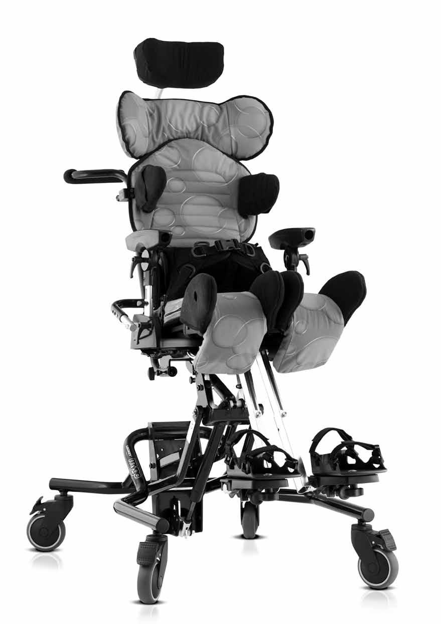
|
- Gyles Hamilton
- 5 years ago
- Views:
Transcription

1 Mygo Seating System User Instructions
2
3 The Mygo Seating System has been designed to offer a high level of postural positioning while enabling function and mobility. This manual shows how you can quickly, easily and safely make use of all the functions. The instructions on safety and maintenance will ensure that you will enjoy the use of this product for a long time. Contents 01 Intended use 02 Declaration of conformity 03 Terms of warranty 04 Product history record 05 Product training record 06 Safety information 07 How to unpack and assemble the seating system 08 The back pack 09 Fitting the cushions 10 Clinical setup for postural management 11 Frequent adjustments for daily use 12 Cleaning & care information 13 Daily product inspection 14 nnual product inspection 15 Reissuing Leckey products 16 Product servicing 17 Technical information
4 1. Intended Use The Mygo Seating System is an activity chair which has been designed for children with disabilities for use at home, in the school environment or outside, if used on a mobility base. Size 1 is suitable for children aged 3-10 years and Size 2 is suitable for 8-14 years. The seating system has a maximum user weight of 50kg (110lbs) for Size 1 and 60kg (132lbs) for Size 2. The seating system is modular and can be used with a choice of indoor or outdoor chassis. The Hi-low chassis has been designed for use indoors but can also be used outdoors on a level surface. The Hi-low chassis should never be exposed to the elements as this may corrode the metal components. The Mygo seat unit will interface with a range of mobility bases, the details of which can be found at our website, www. leckey.com 2. Declaration of Conformity James Leckey Design Ltd as manufacturer with sole responsibility declares that the Mygo Seating System conforms to the requirements of the 93/42/EEC Guidelines, Medical Device Regulations 2002 and EN12182 Technical aids for disabled persons and test methods. 3. Terms of Warranty The warranty applies only when the product is used according to the specified conditions and for the intended purposes, following all manufacturers recommendations (also see general terms of sales, delivery and payment). two year warranty is provided on all Leckey manufactured products and components. 4. Product History Record Your Leckey product is classified as a Class 1 Medical device and as such should only be prescribed, set up or reissued for use by a technically competent person who has been trained in the use of this product. Leckey recommend that a written record is maintained to provide details of all setups, reissue inspections and annual inspections of this product. 5. Product Training Record (Parents, Teachers & Carers) Your Leckey product is a prescribed Class 1 Medical Device and as such Leckey recommend that parents, teachers and carers using the equipment should be made aware of the following sections of this user manual by a technically competent person: Section 6 Safety Information Section 11 Frequent djustments for Daily use Section 12 Cleaning and Care Section 13 Daily Product Inspection Leckey recommend that a written record is maintained of all those who have been trained in the correct use of this product.
5 6 Safety Information 6.1 lways read instructions fully before use. 6.2 To improve safety we recommend that users should not be left unattended at any time whilst using Leckey equipment. 6.3 Only use Leckey approved components with your product. Never modify the product in any way. Failure to follow instructions may put the user or carer at risk and will invalidate the warranty on the product. 6.4 If in any doubt to the continued safe use of your Leckey product or if any parts should fail, please cease using the product and contact our customer services department or your local dealer as soon as possible. 6.8 When the seat is in use on a Hi-low chassis please ensure that the height adjustment pedal and tilt in space lever are locked off and cannot be adjusted accidentally by other children. 6.9 When the Leckey seating systems are used on the Hi-low chassis we do not recommend that users are moved over uneven surfaces when in the equipment. ll due care and attention should be taken if transporting in and out of the seat Never leave the product on a sloping surface, greater than 5 degrees. lways remember to lock all the castors Only use the push handle to steer and move the seat from one area to another. Never use the tray for this purpose. 6.5 Carry out all positional adjustments and ensure that they are securely fastened before you put the user into the product. Some adjustments may require the use of a tool which is provided with each product. Keep all tools out of reach of children The product contains components which could present a choking hazard to small children. lways check that locking knobs and bolts within the child s reach are tightened and secure at all times. 6.6 When putting the user into a seating system, both for positional and safety reasons, always secure the pelvic harness first. 6.7 When the product is stationary ensure that all castors are locked and facing away from the base, as this will improve product stability. This is especially important when the tilt in space or back recline facility is in use Leckey products comply with fire saftey regulations in accordance with EN However the product contains plastic components and therefore should be kept away from all direct sources of heat including naked flames, cigarettes and gas heaters Do not place objects hotter than 40 o C on the tray.t is in use on a Hi-low chassis please ensure that the height adjustment pedal and tilt in space lever are locked off and cannot be adjusted accidentally by other children.
6 6.15 Clean the product regularly. Do not use abrasive cleaners. Carry out maintenence checks on a regular basis to ensure your product is in good working condition The product is designed for indoor use and when not in use should be stored in a dry place that is not subjected to extremes of temperature. The safe operating temperature range of the product is +5 to +40 deg Celsius lways check the plastic hand knobs on the push handle are tightened securely before you move the seat unit Before using the seating system always check that the interface handle on the seat unit is fully engaged with the chassis. If the handle is not engaged properly the seat unit may come loose and could cause serious injury to the child or carer.
7 Mygo Seating System Crash Test The Mygo Seating System has been crash tested and passed for use in vehicles. It has been tested in its complete configuration on a surrogate base with a Leckey head support attached. If the Mygo Seating System is being used in a vehicle the following points must be adhered to: The Mygo Seating System must be positioned forward facing and used with an Unwin Restraint System and a head support which should be suitably positioned at all times during transportation. The head support is available as an optional accessory with the Mygo Seating System. The Mygo Seating System is crash tested and meets the requirements of ISO16840 part 4. For further details please contact our customer service department. Important These crash test details refer to the Mygo Seating System and interface plate only. If you are using the Mygo Seating System on a wheelchair base, please refer to the wheelchair manufacturer s handbook for crash test details.
8 How to unpack and assemble the seating system 7


9 Check parts Congratulations on purchasing your Mygo Seating System. ll of the parts will be contained in polythene bags with each one clearly labelled. Carefully remove them from the boxes and check all the parts you have ordered. Safety First Keep polythene bags away from children. Some of the accessories will need to be assembled before you attach the seat to the base you have purchased. If you are fitting the seat to a mobility base please ensure you fit the interface plate to the mobility base first. Instructions on how to attach the interface to specific bases will be provided with the interface plate. Once you have checked all the components you are then ready to assemble the Mygo Seating System and attach it to its base. Multi-tool number of adjustments will require the use of the multi-tool, which is supplied with each seat and can be found in the back pack. Size 1 Size 2


10 7.1 Setting the backrest The backrest will be folded down for shipping. Raise it into the vertical position and, while doing so, slide the inner tube into the receiving outer tube. Secure the backrest in an upright position and tighten the socket cap. Check that it is secure and does not move when pressure is applied. If the user thrusts forward or backwards they could cause injury to themselves or their carers. lways make sure the backrest is attached securely. Use caution when inserting inner tube as there could be possible finger nip.

 and slide in the calf supports.")
11 7.2 ttaching the footrests (if ordered) If using the Leckey footrests, remove the seat from the chassis and set the seating system upside down on a work surface. Open up the angle of the leg supports by releasing the two locking levers (), shown, and set to the maximum width. Open the socket caps (B) and slide in the calf supports. Set to the desired position, with the footplates facing forward and retighten the socket cap bolts with the multi-tool. lways make sure the foot plate is attached firmly. B B


12 7.3 ttaching the seating system to the Hi-low chassis djust the height of the chassis to its maximum to reduce risk of back strain while attaching the seat unit. Refer to Section 11 on how to adjust the height of the chassis you have purchased. First release the safety locking pin at the front of the seat. To do this pull the pin out and rotate through 90 degrees. Carefully lift the seat and place it into the chassis. t the rear of the underside of the seat you will see a receiving channel. Place this securely over the tube towards the back of the chassis. Pull the handle at the front of the seat unit up and then pivot the seat forward and down. Once the front of the seat is lowered fully, release the handle and push it forward to ensure it has fully engaged on the front tube. Rotate the safety locking pin so it engages in front of the handle. If it hits the handle then the seat is not inserted properly. Remove and repeat process outlined above. lways check the handle and locking pin are fully engaged before you place the child in the seating system. If the handle is not engaged properly the seat unit can come loose and could cause serious injury to the child or carer.
, which need to be pressed in when inserting the lower stems. Push the stems in until the poppers protrude from the other end of the receiving tubes.")
13 7.4 ttaching the push handle The push handle is attached to the Hi-low chassis by inserting the two lower stems into the receiving tubes as shown. The push handle has safety poppers (), which need to be pressed in when inserting the lower stems. Push the stems in until the poppers protrude from the other end of the receiving tubes. Secure the handle in place by tightening the locking knobs (B). Check these regularly to make sure the knobs are tight, particularly if you are moving the product unit along corridors that may have uneven or sloping surfaces. B

.")
 is attached in the same way as the Leckey headrest.")
14 7.5 ttaching the headrest To attach the head support slide the stem into the reducing sleeve () and receiving bracket. Ensure the slot in the reducing sleeve is aligned with the slot in the receiving bracket. Set to the desired position and secure using the hand lever (B). The Mygo Seating System has been designed to interface with Whitmyer head supports. The Whitmyer Lynx headsupport (C) is attached in the same way as the Leckey headrest. To attach Whitmyer Pro-Series headsupports remove the spacer collar (D) from the receiving bracket and lock the vertical stem in position using the ratchet handle. C B D B


 provided with the new spacer")

15 7.6 ttaching the shoulder section 7.7 ttaching the lateral supports To attach the shoulder section to a Size 1 Mygo, remove the headrest mounting bracket by removing the bolts (). Insert the shoulder section bracket and supplied spacer plate between the backrest and the headrest mounting bracket. Bolt back together. Secure the two metal tabs with additional screws (B) provided with the new spacer plate. The screws are attached from the front. Check it is securely fastened. While holding the components together, remove the plastic knob and washer. lign the plastic angle adjuster mouldings and lateral bracket with the slot in the backrest and refit the washer and plastic knob. B B

16 7.8 ttaching the kneepads 7.9 ttaching the sandals ttach the knee pads with the snap fasteners to the knee guides on the sides of the upper legs supports. If sandals are required they can be attached to the footplates with a single fixing bolt. To position the sandals simply loosen the knob (B) under the footplate, select the position you require and re-fasten the knob. B

17 7.10 ttaching the armrests 7.11 ttaching the tray Open the receiving bracket by loosening the ratchet handle () and insert the armrest. Ensure that the popper (B) has locked securely. Retighten the ratchet handle. The tray is attached to the seat by inserting the tray tubes through the centre of the armrest. Once the tray is located in the position the knob () should be tightened securely. B
 in the tray slot and")
 and tighten the plastic knob")
.")
18 7.12 ttaching the grab rail 7.13 ttaching the Hip Laterals To attach the grab rail, insert the receiving brackets () in the tray slot and secure with the plastic knob (B). Repeat on the other side and then slide the tubes into the receiving brackets () and tighten the plastic knob (C). Hip laterals are used with the Pelvic Cradle. First remove the Pelvic Harness brackets if required by removing the screw and flange nut (). Lift the piece of polypropylene on the front of the sacral support. Place the hip lateral brackets into the slots and attach using the flange nuts (B) and screws (C) provided. The flange nuts should go on the front side of the sacral support. B C
 using the Leckey tool and a 10mm spanner and remove the screw and washers (b).")
19 7.14 Retrofitting the Dynamic Backrest To replace the standard static backrest with the dynamic backrest first of all you will need to remove the screw (c) at the top of the standard backrest assembly. To do this loosen the nut (a) using the Leckey tool and a 10mm spanner and remove the screw and washers (b). gain using the Leckey tool and the 10mm spanner, loosen the nut (a) at the bottom of the standard backrest assembly then remove screw (c) saddle washers (d) and standard washers (b).
, nut (a), saddle washers (d) and standard washers")
.")
, nut (a) and washers (b), secure the new dynamic")
.")
20 To fit the dynamic backrest, insert the strut into the bottom bracket as shown. Use the provided screw (c), nut (a), saddle washers (d) and standard washers (b) to secure in place. Please ensure that the screw thread protrudes through the nut (a). Now raise the dynamic strut and insert into the top bracket as shown. Using the provided screw (c), nut (a) and washers (b), secure the new dynamic backrest in place as shown. Ensure that the bolt goes through the centre of the assembly as shown (f). Finally fit the domed cap (e). Use caution when assembling and fitting the dynamic backrest as there is a minor risk of finger nipping.


21 7.15 ttaching the obliquity pads To attach the obliquity pads first remove the base cushion. Set the obliquity pad panel in place with the holes on the tab over the snap fastener. Insert foam as required and refit the base cushion. B C

 side tubing. Please refer to specific assembly instructions supplied with your interface for correct positioning on your base.")
22 7.16 Interfaces for wheelchair and pushchair bases The set up and attachment of the Mygo seat to any mobility base should be completed by a technically competent person who is familiar with the set up of the mobility base. Interface attachment to 16 wide mobility base The universal interface has been designed to enable the Mygo Seat to be attached to any standard 16 (405mm) wide mobility base that has been constructed from 1 (25.4mm) side tubing. Please refer to specific assembly instructions supplied with your interface for correct positioning on your base. The Interface plate should be fitted by a qualified technician who is technically competent in the set up of the mobility base. The position of push handles, leg hangers and armrests on the mobility base may need to be adjusted depending on the size and weight of the child to ensure the stability of the seat. lways refer to the mobility base manufacturer s guide lines for correct set up, paying particular attention to product centre of gravity and stability. Users should not be left unattended at any time whilst using Leckey equipment.
23 The back pack 8

24 8.1 Back pack contents 8.2 ttaching the back pack The back pack contains the activity setting record cards and indicator cards, Mygo colouring cards, Leckey colouring pencils, Mygo user manual and a Leckey multi-tool. Only fit the back pack once the system has been set up. The back pack is easiest to fit once you remove the back cushion. It is attached by elasticated straps which stretch over the back plate. They will also stretch over the lateral supports if they are fitted. Once in place refit the back cushion.

25 8.3 Cards and colouring pencils The kids can write their name, draw a picture or colour in the card to make the seating system uniquely theirs.

26 8.4 ctivity Setting Record Cards and indicator cards The indicator card contains stickers which can be applied to the clear strip on the side of the back adjuster. They are designed to indicate the preferred position or back angle for different activities. The activity setting record cards are used to list the different activities the therapist wishes to carry out in class, or at home. They will describe the new setting and the nature & duration of the activity. The back pack contains small components which could present a choking hazard to small children. lways check that the zip is closed. Users should not be left unattended at any time whilst using Leckey equipment.
27 Fitting the cushions We suggest the cushions are fitted in the following order: 1. Femoral cushions (if applicable) 2. Seat base cushion 3. Sacral cushion 4. Pelvic belt 5. Hip laterals 6. Trunk harness 7. Backrest 8. Laterals 9. Shoulder support 10. Chest harness 11. Knee pads 12. Headrest 9

28 9.1 Femoral cushions (Size 1 only) Slide a femoral cushion onto each of the femoral supports and stick them together in the centre using Velcro. The cushions should be fitted before the seat base cushion and applies to Size 1 only.

.")
.")
 underneath the seat.")
29 9.2 One piece Seat base cushion The seat base cushion can be attached by simply setting it in place, then pressing down to locate the back snap fastener (). To secure further, attach the two side snap fasteners (B). Hook the elastic tabs (C) to the upper leg guide locking lever (D) underneath the seat. lways check the seat base cushion is secure before placing the child in the seat. D C B
 The flexible sacral cushion can be attached by sliding it over the")
 into the pockets on the outer face of the")
 on the")
30 9.3 Flexible sacral cushion 9.4 Pelvic harness (Size 1 or Size 2) The flexible sacral cushion can be attached by sliding it over the plastic tongue, using the fixing snap fastener to secure in place. The Pelvic Harness is attached by sliding the hip guides () into the pockets on the outer face of the harness. It is adjusted to the desired position by securing it to one of the snap fasteners (B) on the adjustable hip guide bracket. The buckle on the tie down strap is clipped into a receiving buckle (C) on either side of the seat base. Finally secure the pelvic harness by attaching the centre plastic buckle (D). B C D

 to secure.")
31 9.5 Pelvic Cradle (Size 2 only) 9.6 Gluteal Ramp Fasten the Pelvic Cradle and place on the seat base cushion. It is labelled to indicate the correct orientation. Press Velcro onto the seat base cushion and attach four buckles () to secure. There are two buckles at the back of the seat and one on either side. If a gluteal ramp (B) is required, attach it to the Pelvic Cradle using the velcro side. B

32 9.7 Hip laterals These hip laterals are used with the Pelvic Cradle only. Slide the cushion covers over the hip laterals hardware with the velcro flap to the outside. Wrap the two velcro straps () round the bracket and stick onto the velcro pad (B). Close over the flap. B


. Simply attach the trunk harness to the connecting straps.")
33 9.8 Trunk harness With your trunk harness you will receive four adjustable side straps, two shoulder straps and brackets, the bolts, washers and locking nuts. Fix the connecting straps to the backrest before attaching the trunk harness. To attach the connecting straps in the shoulder area of Size 1, slide the bracket into the slot () and set at the desired height using the bolts and washers provided. The remaining four adjustable side straps are attached directly without using brackets, to the receiving holes either side of the backrest (C). Simply attach the trunk harness to the connecting straps. The side straps are adjustable in length to accommodate outdoor clothing. For Size 2 the shoulder straps should be attached into the shoulder section (B), rather than the backrest. B B C C


34 9.9 Backrest cushion If you have lateral supports fitted to your seat, adjust them to their maximum width before attaching the backrest cushion. Slide the cushion down over the flexible sacral cushion and secure in place using the four snap fasteners in the backrest moulding. lign the lower fasteners first and snap in place, then secure the top fasteners.
 To attach the lateral support padded cushions,")

.")
35 9.10 Lateral support padded cushions 9.11 Shoulder support cushion (if applicable) To attach the lateral support padded cushions, simply slide the cushions on with the padded side towards the inside of the seat. Feed the plastic buckle through the slot in the cover, then bring the two Velcro fastener straps around the bottom of the moulding and attach them to the Velcro panel as shown. Close over the flap. First loosen the shoulder support laterals (see section 10). Slide the cushion over the assembly and secure using snap fasteners () in four places.


36 9.12 Chest harness 9.13 Knee pads The chest harness can be attached by clipping the male buckle () into the female buckle at either side of the lateral supports. ttach the knee pads with the snap fasteners () to the knee guides on the sides of the upper leg supports.


37 9.14 Contoured headrest cushion To attach the headrest cushion first place the polypropylene reinforcement between the cushion cover and the headrest assembly. It should not be zipped inside the cushion cover. Then place the cushion onto the head support. Snap the central fastener and two side fasteners in place. Bring the lower flap under the head support and attach the velcro.

38 9.15 Flat headrest cushion Place the cushion on to the head support. Secure the central fastener. Bring the lower flap under the head support and secure with the two remaining fasteners. The headrest lateral covers are attached in the same way as the lateral support padded covers.
39 Clinical setup for Postural Management. The clinical setup of the product should be completed by a technically and clinically competent person who has been trained in the use of the product. Leckey recommend a written record is maintained of all clinical setups for this product. Set the backrest height, seat depth and footplate height before placing the child in the seat. These can be fine tuned when the child is in the seat. 10
.")

 at the sides to fit the Pelvic Cradle to the user.")
40 10.1 Pelvic Harness 10.2 Pelvic Cradle To adjust the depth of the pelvic harness, move the snap fastener to either position (B or C). djust the support straps to the required length. Ensure the buckle connects securely in the middle (D). If using the seat outdoors and your child is wearing a coat, position the pelvic harness under the coat. The Pelvic Cradle should be flat and open when the user is placed into the Kit Seating System. ll four side and back buckles should be already attached to the seat. First fasten the buckle () at the front of the Pelvic Cradle. Then fasten the Velcro (B) at the sides to fit the Pelvic Cradle to the user. Then adjust the front and rear straps (C) and (D) to secure to position the user s pelvis. lways attach the pelvic strap first before making any other adjustments. C B D
 To")


41 10.3 Hip Laterals (with Pelvic Cradle only) To set the width of the hip guides loosen the llen bolts (), adjust to the desired width and retighten. B C D

42 10.4 Backrest depth The backrest depth is adjusted by depressing the popper then sliding the back support tube to the desired position. This is very important as it will ensure the seat will fit the child, both when they are upright and in a recline position. There are three settings where the popper can be located. We recommend that you measure the child s upper leg length to define the required seat depth (SD). To do this measure from the child s lower back to the back of their knee. Then set the backrest to position, B or C based on the table below. This backrest depth should not be adjusted while the child is in the seating system. Backrest depth Position Position B Position C Size 1 (SD) mm inches mm inches mm inches Size 2 (SD) mm inches mm inches mm inches SD C B

43 10.5 Backrest height The overall height of the backrest can be adjusted by loosening the two socket cap bolts, then positioning to the required shoulder height of the user. Once in position the socket cap bolts should be retightened securely. The height can be fine tuned when the user is in the seat. Use caution when adjusting to minimum setting as fingers could become trapped between moving and static parts.

 on a card.")
44 10.6 Backrest angle The backrest can be angled by loosening the bolt (). Select the position you require then retighten the bolt securely. lways ensure the back angle is secure to maintain the desired posture for the child. The backrest angle can be adjusted with the child in the seat, but always support the backrest with one hand. lways make sure the bolt is secure as this could cause injury to the child or carer. There are two angle indicator strips on either side of the back adjuster. We have supplied angle location markers (shown below) on a card. These can be applied to the clear strip on the adjuster tube to indicate the desired positions for various activities such as rest, feeding, play. The angle indicator strip indicates the angle from the seat cushion to the backrest. The black and yellow hazard strip on the inner tube indicates the maximum forward or prone position the backrest can be adjusted to.
, slide the backrest strut to the bottom, retighten the handle.")
 and adjust the backrest. Pull the locking pin (c). Ensure that the locking pin is secure.")
45 10.7 djusting the Dynamic Backrest To achieve the required amount of dynamic movement loosen the handle (a), slide to the required position and retighten securely. To return the backrest to a static position, loosen the handle (a), slide the backrest strut to the bottom, retighten the handle. To angle adjust the backrest where a dynamic backrest has been fitted, you use the handle at the base of the backrest. Pull the locking pin (c) and twist and unlock. Lift up the handle (b) and adjust the backrest. Pull the locking pin (c). Ensure that the locking pin is secure. The range of the backrest angle and the range if dynamic movement are a maximum of 30, i.e. if the backrest is upright, a full 30 is available on the dynamic system. If the backrest angle is at 10 then only 20 of movement is available with the dynamic backrest and so on. The backrest must be in the upright position with the dynamic function locked off (i.e. the handle to the lowest position on the backrest supine) and ensure the locking pin (c) is engaged when the seating system is used in transport.


46 10.8 djusting the upper leg supports The upper leg supports will be set at the minimum position on arrival. Set the depth before placing the child in the seat. Fine adjustment is possible afterwards but is restricted by the user s weight. To achieve the correct position measure the length from the child s lower back to the back of their knee. For Size 1 adjust the supports to the desired position using the locking lever () underneath the seat base. To adjust, press the locking button and release. Keep the supports pointing straight forward at this time unless wind sweeping or adduction, abduction must be accommodated, in which case set the angle accordingly using the locking lever again. For Size 2, loosen the locking levers under the seat and slide leg support to required position. Keep the supports pointing straight forward at this time unless wind sweeping or adduction, abduction must be accommodated, in which case set the angle accordingly. Retighten bolt. To increase the angle further, remove bolt and move leg angle to wider setting. Insert bolt into second slot (B) and tighten. The supports can be readjusted once the child has been placed in the chair. B B
 on the underside of the leg support.")

47 10.9 Upper leg guide lateral supports To adjust the width of the knee supports on Size 1, loosen the bolts () on the underside of the leg support. Set to the desired width and retighten. To adjust the width or angle or angle on the lateral supports on Size 2, loosen the bolts (B) from above, move the guides and retighten the bolts. B

48 10.10 Footplate height To set the height of the footplate loosen the bolt () on the front of the calf support tube and slide the footplate to the required height and retighten the bolt. To set the correct height of the footplate measure the distance from the back of the child s knee to the bottom of their heel. You may have to adjust the angle to achieve the required foot position. To adjust the angle loosen the bolt (B) with the multi-tool, set to the desired angle and retighten. There is a safety popper to indicate maximum safe extension. This can be set with the child in the seat. lways check the footplate is secure to prevent the user sliding forward and down in the seat which could pose a choking hazard if a chest or trunk harness is attached. B
 to select the angle you require. The footplates can simply flip up to aid transfer.")
49 10.11 Footplate angle adjustment To set the angle to accommodate plantarflexion or dorsiflexion, simply loosen or tighten the hand knob () to select the angle you require. The footplates can simply flip up to aid transfer.


 to adjust the width, height and angle of the lateral supports and retighten when you have")
50 10.12 Flexible sacral support Lateral supports The flexible sacral support is used in conjunction with the pelvic positioning harness or Pelvic Cradle. To adjust the height, depth and angle, loosen the bolts on either side with the multi-tool provided. djust the support to the correct angle then retighten the bolts. The support will flex back and forward to assist the child into the preferred posture. Loosen the socket cap () to adjust the width, height and angle of the lateral supports and retighten when you have achieved the desired position. To move flip away laterals, use knob B. lways use caution to ensure fingers do not become trapped when adjusting the sacral support. B
 on one side and one pelvic harness clip (B).")
 and snapping into place. Then connect the shoulder straps (E) into the clips at the top.")
51 10.14 Chest harness Trunk harness To change the width of the chest harness. Lift the front cover, adjust the Velcro straps to the desired width and replace the cover. When the child is out of the seating system the trunk harness will be open but remain attached by two side clips () on one side and one pelvic harness clip (B). When placing the child in the seating system bring the trunk harness across the front and attach by connecting the clips into the buckles on the other side (C). Connect the remaining straps into the pelvic harness or Pelvic Cradle by feeding them through the loop (D) and snapping into place. Then connect the shoulder straps (E) into the clips at the top. If your child is wearing outdoor clothing, the side straps can be opened by releasing the snap fasteners. The pelvic harness connecting strap can be released by moving the strap to the lower snap fastener position. ll the connecting straps are adjustable by lifting the cover, adjusting to the desired length and replacing the cover. Check the laterals and harnesses regularly to ensure they have not become loose as without appropriate trunk support the child may be at risk of slipping into a position they cannot recover from. This could present a choking hazard.
52 E E C C D B

53 10.16 djusting the knee pads Sandals The kneepads can be used as a limiter to help prevent the child from sliding forward in the seat. It can also be used above the knee to prevent the child from raising their foot. To adjust the knee pads lift the front cover adjust the Velcro straps to the desired length and reposition in place. To remove unclip the snap fastener on one side. To position the sandals simply loosen the knob () under the footplate, select the position you require and re-fasten the knob. To position the user s feet in the sandals secure the Velcro ankle and toe straps provided. If sandals are not required Velcro straps are provided for foot positioning.
 and when set to the desired position retighten the knobs.")
54 10.18 Shoulder Support Laterals (Size 2 only) Contoured headsupport To adjust the angle of the shoulder support laterals, loosen screw, move laterals to required angle and retighten. To adjust the height, depth and angle of the contoured headrest, loosen the hand knobs () and when set to the desired position retighten the knobs. Do not remove the headrest while the user is in the seat. Never use the headrest to force the position of the user s head. lways use caution to ensure fingers do not become trapped when adjusting the headrest.
, as shown on the contoured head support.")
, set to the desired height and retighten.")
55 10.20 Flat headrest with lateral supports rmrest adjustment To adjust the height, depth and angle of the flat headrest, adjust using the hand levers (), as shown on the contoured head support. To adjust the width of the laterals loosen plastic knob (B), slide to desired position and tighten securely. To adjust the height of the armrest loosen the hand knob (B), set to the desired height and retighten. To adjust the angle, rotate ratchet handle () until the desired position has been achieved. To remove the armrest completely, loosen ratchet handle (C), press popper (D) and lift the armrest. lways use caution as fingers could become trapped in the slot when adjusting the height. B C B D
56 10.22 Tray djustment Grab rail adjustment The height and angle of the tray are set by adjusting the armrests as detailed above. To remove or adjust the depth of the tray loosen the knobs () under the armrest, set to the desired position and re-tighten securely. lways use caution to ensure the child s hands or arms do not become trapped when inserting the tray. To set the depth of the grab rail to suit the child s reach, loosen knob (), adjust to the required depth and then re-tighten. Do not adjust the horizontal bars beyond the moulding, except when you are removing the tray. Never use the tray to steer or push the chair. Do not place objects, hotter than 40 degrees Celsius on the tray. Please note that the tray is for the use of the user only. Do not lean or place objects on the tray, greater than 8kgs (17.6lbs).
57 Frequent adjustment for daily use (therapists/ carers/parents) Parents and carers should be shown how to make frequent adjustments and be made aware of the safety checks in Section 6 by a technically and clinically competent person who has 11 been trained in the use of the product. Leckey recommend that a written record is maintained of all parent and carers who have been trained in the use of this product.

58 11.1 Transferring your child into and out of the seat Before transferring the child into the seat carry out the daily product inspection as outlined in section 13 of this user manual. djust the seat to a comfortable height to facilitate transfer. Lock all the castors, ensuring that they are facing outwards to maximise product stability. Make sure the safety buckle on the chest harness is released and is out of the way to facilitate transfer. If the seat has flip-away thoracic laterals, first move these out of the way using knob. Unclip the pelvic harness or Pelvic Cradle in the middle, undo the side velcro of the Pelvic Cradle and allow the harness to open out to facilitate transfer. Lastly if sandals are fitted open the straps. You are now ready to transfer or hoist the child into the seat. The pelvic harness and Pelvic Cradle are fastened using the middle buckle, and side velcro (in the case of the Pelvic Cradle). lways secure the pelvic harness or Pelvic Cradle first before fastening other buckles or harnesses. djust the harness so the child cannot slide or creep forward in the seat.


 and the velcro tabs (D).")

59 11.2 djusting the pelvic harness or Pelvic Cradle The correct positioning and tensioning of the pelvic harness or Pelvic Cradle is key to a child s postural management, affecting their comfort and ability to carry out activities. Please consult with your therapist to ensure the harness is positioned correctly and that the straps are tensioned appropriately. To tension the Pelvic Cradle use the 4 side straps (C) and the velcro tabs (D). If using the seat outdoors and your child is wearing a coat, position the pelvic harness or Pelvic Cradle under the coat. To tension the pelvic harness straps and pads around the child pull the centre strap (). Pull the two side straps up to fine tune the pelvic position and adjust (B) the height of the pads on the hips. Pelvic harness (Size 1 or Size 2) Pelvic Cradle (Size 2 only) B C C

60 If the child is active or has extensor spasms check the Pelvic harness or Pelvic Cradle is secure after each spasm to ensure the child is safe and cannot slide forward in the seat. lways fasten the centre buckle on the pelvic harness or Pelvic Cradle before making any other adjustments. D C


61 11.3 Chassis 11.4 Powered height adjustment The Mygo Seat is designed to fit onto a range of chassis. This user manual shows the correct and safe use of the seating system with the Leckey Hi-low chassis. For all other chassis or bases please refer to the manufacturer s handbook. To prepare the Hi-low chassis for the seating system we recommend that you raise the chassis to a comfortable working height by pressing the foot lever at the rear of the chassis or by pressing the up button on the handset of the powered option. The powered chassis can be easily adjusted with the push button control handset. The seat can be height adjusted with the client in the chair. Before the product is used for the first time it is recommended that the battery should be fully charged for 12 hours. To do this plug the adaptor into the mains socket and attach the lead () to the battery and switch on the mains supply power. When charged switch off mains power, remove the adaptor plug and disconnect the lead from the battery. The battery charge should be topped up each day for approximately one hour. The chair can be adjusted in height while connected to the mains.

 on the right hand side of the pedal.")
62 11.5 Height djustment Hi-low chassis You can carry out this adjustment with the child in the chair. To adjust the height of the Hi-low chassis press the foot lever at the rear of the chassis or press the up button on the handset of the powered option whilst holding the push handle. Once you remove your foot from the pedal or your thumb from the handset the seat will be fixed at the chosen height. For safety the height adjustment pedal on the chassis can be locked by engaging the pull pin (C) on the right hand side of the pedal. To unlock pull the pin out and rotate 90 degrees, the pedal can then be operated. The locking pin (C) should be kept in the locked position when you are not adjusting the chassis. lways keep the locking pin engaged when you are not adjusting the chassis. This will prevent the foot pedal being operated accidentally. For children over the weight of 27kg (60lbs), raising the manual chassis is a 2 person lift (UK lifting and handling regulations). lways use caution as hands could become trapped when height adjusting the base. c

63 11.6 Tilt in space The tilt in space can be angled while the user is in the seat. Before you adjust the tilt in space angle of the seat always ensure the pelvic harness is secured preventing the user from sliding forward in the seat. To adjust the tilt angle press the lever under the seat base. Once you have selected the angle you require, by simply removing your hand from the lever, the chair will be locked in position. The tilt in space should be locked off while the user is in the seat. To lock the lever twist the pull pin to the right hand side of the lever and the pin will pop into position. You may have to lift the lever slightly to allow it to lock. To unlock pull the pin out and rotate 90 degrees, the lever can then be operated. lways keep the tilt in space lever in the locked position to prevent accidental actuation of the lever which could cause the seat unit to jolt and possibly cause injury to the child. Please use handle bars when operating tilt in space. lways check with your therapist that the use of tilt in space will not cause any obstructions to the child s airways. Lever Locking pin
64 11.7 djusting the Dynamic Backrest To return the backrest to a static position, loosen the handle (a), slide the backrest strut to the bottom, retighten the handle. The backrest must be in the upright position with the dynamic function locked off (i.e. the handle to the lowest position on the backrest supine) and ensure the locking pin (c) is engaged when the seating system is used in transport.

65 11.8 Chest and Trunk Harness adjustment If the child requires chest support as part of their postural support programme the seat will be fitted with rigid laterals or a combination of laterals, chest harness and trunk harness. These may need to be adjusted on a daily basis to accommodate differences in clothing. lways check with your therapist as to the optimum positioning and tensioning of the straps and support items for the child. To change the width of the chest harness, lift the front cover, adjust the Velcro straps and set to the desired width. When the correct width has been achieved replace the cover. Please refer to section 10 for specific guidance on adjusting the trunk harness. lways make sure the plastic buckles are fully engaged when using the chest harness. Check the harness and laterals are secure to ensure the child is safe and cannot slide forward in the seat as this may restrict their breathing.

66 11.9 Sandals Tray adjustment To position the user s feet in the sandals secure the Velcro straps provided so the foot is held in place. The straps should be placed over the bridge of the foot and over the toes. If the child is wearing sandals or light footwear check the straps to make sure the webbing does not irritate the skin. The activity tray can be used for a range of functions and its position can be fine tuned to suit the user and the activity whether it is for fun, education or feeding. The tray is attached to the seat by inserting the tray tubes through the centre of the armrest. Once the tray is located in the position the knob () should be tightened securely. djust the armrests to set the height and angle of the tray.
67 11.11 rmrest adjustment lways use caution as fingers could become trapped in the slot when adjusting the height. lways use caution to ensure the child s hands or arms do not become trapped when inserting the tray. Never use the tray to steer or push the chair. To adjust the height of the armrest loosen the hand knob (B) set to the desired height and retighten. To adjust the angle rotate hand knob () until the desired position has been achieved. To remove the armrest completely for side transfer or assist in getting the child into or out of the seat loosen hand knob (C), press popper (D) and lift the armrest. Do not place hot objects, greater than 40 degrees Celsius on the tray.. Please note that the tray is for the use of the user only. Do not lean or place heavy objects on the tray, not greater than 8kgs (17.6lbs). B C D
68 11.12 Grab rail adjustment To set the depth of the grab rail to suit the child s reach loosen knob (), adjust to the required depth and then re-tighten. Do not adjust the horizontal bars beyond the mouldings, except when you are removing the tray. To remove quickly, loosen knob (B) at either side and slide rail up vertically. B


69 11.13 Frequent djustments To achieve the required amount of dynamic movement loosen the handle (a), slide to the required position and retighten securely. To return the backrest to a static position, loosen the handle (a), slide the backrest strut to the bottom, retighten the handle. To angle adjust the backrest where a dynamic backrest has been fitted, you use the handle at the base of the backrest. Pull the locking pin (c) and twist and unlock. Lift up the handle (b) and adjust the backrest. Pull the locking pin (c). Ensure that the locking pin is secure. The range of the backrest angle and the range if dynamic movement are a maximum of 30 o, i.e. if the backrest is upright, a full 30 o is available on the dynamic system. If the backrest angle is at 10 o then only 20 of movement is available with the dynamic backrest and so on. The baqckrest must be in the upright position with the dynamic function locked off (i.e. the handle to the lowest position on the backrest supine) and ensure the locking pin (c) is engaged when the seating system is used in transport.

70 12 Cleaning & Care Information How to Maintain When cleaning we recommend that you use only warm water and a non-abrasive detergent. Never use organic solvents or dry cleaning fluids. Upholstery and fabrics 1. The cushion covers can be removed, machine washed at 40ºC and tumble dried at a low temperature. Please remove the foam from the following covers before washing: Headrest Shoulder support Backrest cushion Seat base cushion ll other soft upholstery can be placed into the washing machine intact, after removing bolts and fastenings. 3. Staining should be removed as quickly as possible with absorbent cloth, towels or a sponge. Routine soap and warm water sponging is effective for ordinary soiling and minor spills. Be careful not to over wet the fabric as this will cause the staining to spread. 4 ntiseptic cleaning agents can be used on more stubborn stains. These may require a safe solvent such as Isopropyl lcohol or Mineral Spirit. half cup of household bleach to 5 litres of water can also be used as a useful disinfectant. 5. The pelvic and trunk harnesses can be machine washed at 40 Deg C. Make sure all bolts and fasteners are removed first as they may cause damage to your washing machine. Store these in a safe place and out of reach from children. 6 lways ensure the product is dry before use. Metal and plastic components 1. Soap and water or antibacterial spray can be used for daily cleaning. 2. For deep cleaning a low pressure steam cleaner can be used. 3. Do not use solvents to clean plastic or metal components. 4. Make sure the product is dry before use. 2. The upholstery and fabrics can also be cleaned by hand whilst in place. When cleaning we recommend that you use only warm water and a non-abrasive detergent.
71 13 Daily Product Inspection (Therapists, parents & carers) We recommend that daily visual checks of the equipment are carried out by therapists, carers or parents to ensure the product is safe for use. The recommended daily checks are detailed below. 1. Check that there is no lateral movement or wobble in any of the moving parts. Ensure all adjustment knobs and bolts are in place and secure. 2. Check all upholstery and Velcro for signs of wear and tear. 3. Check all castors are moving freely and lock securely. 4. Ensure the handle and locking pin on the seat interface plate is fully engaged and the seat unit is securely fixed onto the chassis. 5. Ensure the pelvic harness is fully secured around the user and they cannot slide or creep forward in the seat. 6. Ensure the footplate is attached securely. If in any doubt to the continued safe use of your Leckey product or if any parts should fail, please cease using the product and contact our customer service department or your local dealer as soon as possible.
72 14 nnual Product Inspection (Therapist, Technician, Leckey Product dvisor, Dealer) Leckey recommend that each product should be subject to a detailed inspection at least once a year and every time the product is reissued for use. This inspection should be carried out by a technically competent person who has been trained in the use of the product and should include the following checks as a minimum requirement. 1. Check that there is no lateral movement or wobble in any of the moving parts. Ensure all adjustment knobs and bolts are in place and secure. 2. Check all ratchet handles, knobs, nuts, bolts and plastic buckles are in place, replacing any missing items. Paying particular attention to the following items; > Headsupport locking bolts. > Backrest height and angle adjustments bolts. > Seat depth adjustment bolts. > Pelvic harness / hip guide attachment bolts. > Footrest height and angle adjustment. 6. Lift the base to check each castor individually. Make sure they are moving freely and remove any dirt from the rubber wheels. Check that the brakes lock the wheels securely. 7. Visually check the structure of the product paying attention to weld points on the frame ensuring there are no signs of fatigue or cracking around the welds. 8. Leckey recommend that a written record is maintained of all annual product inspections. If in any doubt to the continued safe use of your Leckey product or if any parts should fail, please cease using the product and contact our customer service department or your local dealer as soon as possible. 3. Check the chassis height adjustment mechanism is working properly. If the chassis is foot pedal operated ensure the seat height doesn t change when the pedal is released. lso, check that the locking pin engages securely to prevent accidental height adjustment of the chassis. 4. djust the seat to its maximum range of tilt in space and ensure that the locking lever locks the seat out securely at varying point in this range. 5. Check that where the seat and chassis join there is no visible wear and tear on the metal components.
73 15 Re-issuing Leckey Products 16 Product Servicing Most Leckey products are assessed and ordered to meet the needs of an individual user. Before reissuing a product we recommend that the therapist prescribing the product has carried out an equipment compatibility check for the new user and has ensured that the product being re-issued contains no modifications or special attachments. detailed technical inspection should be carried out on the product prior to re-issuing. This should be carried out by a technically competent person who has been trained in the use and inspection of the product. Please refer to section 14 for the required checks to be carried out. Servicing of all Leckey products should only be carried out by technically competent persons who have been trained in the use of the product. In the UK & ROI please contact the Leckey Service Centre on UK or ROI and our customer service department will be delighted to assist you with your servicing requirements. ll international service enquiries should be directed to the appropriate Leckey distributor who will be delighted to assist you. For further information on Leckey distributors please visit our website Ensure the product has been cleaned thoroughly in accordance with section 12 of this manual. Ensure a copy of the user manual is supplied with the product. copy can be downloaded from our website Leckey recommend that a written record is maintained of all product inspections carried out during the reissue of the product. If in any doubt to the continued safe use of your Leckey product or if any parts should fail, please cease using the product and contact our customer service department or your local dealer as soon as possible.
Mygo Seating System User Instructions
 Mygo Seating System User Instructions The Mygo Seating System has been designed to offer a high level of postural positioning while enabling function and mobility. This manual shows how you can quickly,
Squiggles Seating System User Instructions
 Squiggles Seating System User Instructions The Squiggles Seating System has been designed to offer a high level of postural positioning while enabling function and mobility. This manual shows how you
Everyday Activity Seat. User Instructions
 Everyday ctivity Seat User Instructions The Everyday ctivity Seat is a moderate seating system designed for use in the home and classroom. It comes in 3 sizes with adjustable seat height, depth and width
Kidwalk Seating System User Instructions
 Kidwalk Seating System User Instructions The Kidwalk has been designed as a posturally supportive mobility system that moves with the child giving them the freedom to move and walk while keeping their
Kidwalk User Instructions
 Kidwalk User Instructions The Kidwalk has been designed as a posturally supportive mobility system that moves with the child giving them the freedom to move and walk while keeping their hands free to explore
Comfee Seat. User Instructions
 Comfee Seat User Instructions The award-winning Comfee Seat is an innovative, supportive and practical seating system designed specifically for leisure time in the home, school or in respite care. It
KidWalk Dynamic Mobility System
 KidWalk Dynamic Mobility System OWNER S MANUAL ***Note*** Read Owner s Manual before use. Manufactured By Prime Engineering A Division of Axiom Industries, Inc. Distributed in the: United Kingdom and Republic
Phoenix Buggy User Instructions
 Phoenix Buggy User Instructions Issued 1 st March 2015 Introduction Welcome to the Phoenix Buggy User Guide. The Phoenix Buggy has been designed to provide a robust, transportable mobility solution for
Mygo Seat Spare Parts Catalogue
 Mygo Seat Spare Parts Catalogue Contents 03-04 Mygo Seat Complete 05 Backrest Assembly 06 LH Footrest Assembly 07 RH Footrest Assembly 08 Size 1 Abduction Assembly 09-10 Size 2 Abduction Assembly 11 Seatbase
Tandem User Instructions
 Tandem User Instructions Issued 1 st November 2014 Tandem Buggy We designed the tandem buggy to enable families who have a disabled child and another younger child to enjoy the freedom they deserve. The
Advancement Chair. R901, R902, & R903 Product Manual
 Advancement Chair R901, R902, & R903 Product Manual Contents Warnings and Important Information 3 Recommended Use 4 User and Item Dimensions 4 Assembly and Adjustment Information 5 Maintenance 14 Cleaning
USER MANUAL Edition
 USER MANUAL Edition 2 2014 CONTENTS Safety guidelines Transportation Unfolding and folding Tilt in space operation Seat depth and pelvic support adjustment Footrest adjustment Fitting optional accessories
Able Assist Transfer Aids User Manual
 www.drivemedical.co.uk The Team at Drive Medical develops its products to give our customers the freedom to live independently. This encompasses their daily home life and provides them with the opportunity
Booster Car Seat User Guide
 Booster Car Seat User Guide For future use, STORE USER GUIDE in location on bottom of base. IS0133.E 2015 Artsana USA, Inc. If you have any problems with your Chicco Booster Seat, or any questions regarding
Safety, Care & Warranty Information
 Instruction for use part 1 of 2 Safety, Care & Warranty Information August 2017. Version 006 Read part 1 and part 2 before use. Please always refer to the manufacturer or distributor you purchased the
Columbia Car Seat. User Guide. IMPORTANT Please retain this User Guide for future reference. Conforms to ECE R44.03 Universal
 Columbia Car Seat User Guide Conforms to ECE R44.03 Universal IMPORTANT Please retain this User Guide for future reference EXTREME HAZARD: Parents should not under any circumstances use this child restraint
06/15. Hip Spica Chairs. INSTRUCTIONS FOR USE Multi-Adj / Portable / STEPS. Code / 5596 / 5580
 06/15 Hip Spica Chairs INSTRUCTIONS FOR USE Multi-Adj / Portable / STEPS Code 5585-5587 / 5596 / 5580 SECTIONS PAGE START 1.0 MULTI ADJUSTABLE HIP SPICA 2 2.0 PORTABLE HIP SPICA 13 3.0 STEPS HIP SPICA
Neat Zeat. Installation & User manual
 Neat Zeat Installation & User manual IMPORTANT CONSUMER INFORMATION NOTICE: This manual contains important instructions that must be passed on to the user of this product. Please do not remove this manual
Group 0+ Birth to 13kgs (29lbs) Birth to approximately 9-12 months
 Birth to approximately 9-12 months") Ventura Plus Instructions Group 0+ Birth to 13kgs (29lbs) Birth to approximately 9-12 months IMPORTNT, RETIN FOR FUTURE REFERENCE: RED CREFULLY Keep in the pocket provided on your Ventura Plus VERY IMPORTNT
Ventura Plus Instructions Group 0+ Birth to 13kgs (29lbs) Birth to approximately 9-12 months IMPORTNT, RETIN FOR FUTURE REFERENCE: RED CREFULLY Keep in the pocket provided on your Ventura Plus VERY IMPORTNT
KidWalk KidWalk II Dynamic Mobility System
 OWNER S MANUAL KidWalk KidWalk II Dynamic Mobility System Manufactured By Prime Engineering A Division of Axiom Industries, Inc. Supplier Info 70111KWOM 2 TABLE OF CONTENTS This owner s manual is organized
Daytona Car Seat. User Guide
 Daytona Car Seat User Guide IMPORTANT Please retain this User Guide for future reference. Conforms to ECE R44.03 Universal EXTREME HAZARD: Parents should not under any circumstances use this child restraint
AFFIX TM Booster Seat. Owner s Manual PD202326A 5/12
 AFFIX TM Booster Seat Owner s Manual READ THIS MANUAL. Do not install or use this car seat until you read and understand the instructions in this manual. FAILURE TO PROPERLY USE THIS CAR SEAT INCREASES
Duo - Manual User Instructions
 Duo - Manual User Instructions Duo User Information February 2012 Contents 2 Introduction to the Duo chairs 3 Duo Product Range 3 Guidelines for Best Practice 3 Questions and Concerns 4 The User Instructions
Magician Comfy. Owner s Manual
 Magician Comfy Owner s Manual Table Of Contents Introduction...................................... 2 Safety Precautions................................ 3 Assembly........................................4-9
Seating Product Brochure
 Seating Product Brochure VIDA is all about creating the best customer care possible for our clients. It s about the best advice, the best support and the best products, all brought to your door. It s about
Prime Engineering Superstand
 OWNER S MANUAL PRODUCT PHOTO PARTS LIST ASSEMBLY INSTRUCTIONS FITTING & ADJUSTING DAILY USAGE ACCESSORIES MAINTENANCE WARRANTY Prime Engineering Manufactured By Prime Engineering A Division of Axiom Industries
WHEELBASE USER MANUAL
 WHEELBASE USER MANUAL Please read these instructions carefully before setting up and using the NEO Wheelbase 1 Southwest Seating & Rehab Ltd. Introduction The NEO wheelbase is specially designed to accept
contents parts description 1/2 FOLD MECHANISM
 contents 1. Contents 2. Introduction 3. Parts Description 4. Adjustment Features i. Rear Wheels ii. Upholstery Tension iii. Brake Adjustments iv. Leg Rest Adjustment 5. Folding Back Mechanism 6. Disassembly
Marlin Bath Lift BLM-8200 WARNING! Read ALL instructions before using this product!
 Marlin Bath Lift BLM-8200 www.inspiredbydrive.com WARNING! Read ALL instructions before using this product! PRODUCT DESCRIPTIONS Your Marlin Bath Lift has been built to the highest standards of quality
RESTWELL RISE & RECLINE ARMCHAIRS INTALIFT - OWNER S HANDBOOK PARTS DESCRIPTION
 RESTWELL RISE & RECLINE ARMCHAIRS INTALIFT - OWNER S HANDBOOK CONTENTS 1. Introduction 2. Model Description 3. Parts Description 4. Personal Safety 5. Installation Instructions 6. Backrest Removal 7. Operating
Nimbo Lightweight Posterior Posture Walker
 Nimbo Lightweight Posterior Posture Walker Assembly & Operating Instructions with optional Forearm Platforms with optional Pelvic Stabiliser Please read these instructions carefully before assembling or
GoFitTM. Booster Car Seat User Guide. in location on bottom of base. IS0147.2E Artsana USA, Inc.
 GoFitTM Booster Car Seat User Guide For future use, STORE USER GUIDE in location on bottom of base. IS047.2E 207 Artsana USA, Inc. www.chiccousa.com TABLE OF CONTENTS If you have any problems with your
RESTWELL RISE & RECLINE ARMCHAIRS OWNER S HANDBOOK PARTS DESCRIPTION
 RESTWELL RISE & RECLINE ARMCHAIRS OWNER S HANDBOOK CONTENTS 1. Introduction 2. Model Description 3. Parts Description 4. Personal Safety 5. Installation Instructions 6. Backrest Removal 7. Operating Instructions
Explorerfix Child Car Seat. Group 1 & 2. Instructions. Suitable for use from 9kgs (20lbs) to 25kgs (55lbs) Approximately 9 months to 6 years
 to 25kgs (55lbs) Approximately 9 months to 6 years") Explorerfix Child Car Seat Group 1 & 2 Suitable for use from 9kgs (20lbs) to 25kgs (55lbs) Approximately 9 months to 6 years Instructions Important: Keep for future reference Please read these instructions
Explorerfix Child Car Seat Group 1 & 2 Suitable for use from 9kgs (20lbs) to 25kgs (55lbs) Approximately 9 months to 6 years Instructions Important: Keep for future reference Please read these instructions
User Guide Issued 21st February 2011
 User Guide Issued 21 st February 2011 Introduction Page 1 Operating Instructions Page 2 Adjusting the Seat Depth/Hip Guides Page 3 Adjusting the Hip Guides/Seat Height Page 4 Adjusting the Lateral Supports/Headrest
Booster Car Seat. User Guide. in location on bottom of base. IS0174E_ Artsana USA, Inc. 01/19
 Booster Car Seat User Guide For future use, STORE USER GUIDE in location on bottom of base. IS0174E_03 2019 Artsana USA, Inc. 01/19 www.chiccousa.com TABLE OF CONTENTS If you have any problems with your
A passion for posture
 A passion for posture We are passionate about posture. Our experienced team of clinicians and engineers understand the importance of sitting correctly and comfortably, especially for those who do not have
GoFitTM. Booster Car Seat User Guide. in location on bottom of base. IS0147E_ Artsana USA, Inc. 01/19
 GoFitTM Booster Car Seat User Guide For future use, STORE USER GUIDE in location on bottom of base. IS047E_04 209 Artsana USA, Inc. 0/9 www.chiccousa.com TABLE OF CONTENTS If you have any problems with
Therapedic Positioning Restraint System Model #2000 and Model #2500. Instructions for Use
 Therapedic Positioning Restraint System Model #2000 and Model #2500 Instructions for Use MODEL #2000: Use only with individuals who weigh between 20 and 102 pounds (9.1-46.3 kg) and whose height is less
Florien II User Instructions
 Florien II User Instructions Important: Read carefully. Retain for future reference Contents June 2017 Issue 4 1 Introduction to the Florien II Chair 1.1 What is the Florien II Chair? 1.2 Why is there
Owner s Handbook: Ride Java Back Support
 ENGLISH Y i Owner s Handbook: Ride Java Back Support M Ride Designs a branch of Aspen Seating, LLC 8100 SouthPark Way, C400 Littleton, Colorado 80120 USA toll-free (U.S. Only): 866.781.1633 phone: 303.781.1633
ZOOMI INSTRUCTIONS FOR USE Zoomi 13011, 13021, / Zoomi , 13022, 13032
 6/17 ZOOMI INSTRUCTIONS FOR USE Zoomi 13011, 13021, 13031 / Zoomi+ 13012, 13022, 13032 CONTENTS PAGE 1.0 INTRODUCTION 1 2.0 ILLUSTRATION OF YOUR ZOOMI SEATING SYSTEM 2 3.0 ILLUSTRATION OF YOUR ZOOMI +
IMPORTANT. Please read these instructions carefully Before using your wheelchair. Please read Page 8 before using the Tilt in Space facility
 USER MANUAL For TILT and FOLD WHEELCHAIR GAS STRUT MODEL IMPORTANT Please read these instructions carefully Before using your wheelchair Please read Page 8 before using the Tilt in Space facility Authorised.
XChange Seat Service and Maintenance Guide
 XChange Seat Service and Maintenance Guide Table Of Contents Page General Information... 1 Registration Information... 1 Seat Cushion Latch... 2 Lap Shoulder Belt Replacement... 2 Sliding Buckles Replacement...
Delta User Instructions
 Delta User Instructions Delta User Information August 2012 Contents IMPORTANT NOTICE 2 Introduction to the Delta chair 2 Delta Product Information 2 Questions and Concerns 2 The User Instructions 3 Guidelines
Paediatric seating for the Bingo OT. Designed and manufactured by
 Designed and manufactured by Paediatric seating for the Bingo OT A breakthrough in rehabilitative stroller seating Introducing the latest innovation from the designers of the revolutionary SPEX seating
IMPORTANT. Please read these instructions carefully Before using your wheelchair. Please read Page 8 before using the Tilt In Space facility
 USER MANUAL For TILT and FOLD WHEELCHAIR GAS STRUT MODEL IMPORTANT Please read these instructions carefully Before using your wheelchair Please read Page 8 before using the Tilt In Space facility Authorised.
MODEL SST1 JOGGER/BIKE TRAILER. Owner s Manual should be kept for future reference
 PRODUCT REGISTRATION: MAKE SURE TO REGISTER YOUR PURCHASE AT http://allensportsusa.com/about/product-registration TO QUALIFY FOR PRODUCT WARRANTY AND TO RECEIVE IMPORTANT PRODUCT NOTIFICATIONS 1 MODEL
verona user guide IMPORTANT! KEEP FOR FUTURE REFERENCE Conforms to ECE R44/04
 Conforms to ECE R44/04 verona user guide EXTREME HAZARD: Parents should not under any circumstances use this child restraint on a passenger seat equipped with an airbag. IMPORTANT! KEEP FOR FUTURE REFERENCE
Prime Engineering GRANSTAND II
 OWNER S MANUAL PRODUCT PHOTO PARTS LIST ASSEMBLY INSTRUCTIONS FITTING & ADJUSTING DAILY USAGE ACCESSORIES MAINTENANCE WARRANTY Prime Engineering GRANSTAND II Manufactured By Prime Engineering A Division
MADITA-Fun mini. the therapy chair for initial assistance. Instructions for use
 MDIT-Fun mini the therapy chair for initial assistance Instructions for use Dear Customer, t this point we would like to thank you for placing your trust in our company and for purchasing our product.
USER MANUAL PRODUCT CODE: WC CareCo (UK) Ltd, Hubert Road, Brentwood, Essex, CM14 4JE PAGE 1
 Ltd, Hubert Road, Brentwood, Essex, CM14 4JE PAGE 1") by USER MANUAL PRODUCT CODE: WC01059 CareCo (UK) Ltd, Hubert Road, Brentwood, Essex, CM14 4JE PAGE 1 CONTENTS 1. INTRODUCTION 2. IDENTIFICATION OF PARTS 3. SAFETY REGULATIONS 4. SAFETY WARNINGS 5. USER
by USER MANUAL PRODUCT CODE: WC01059 CareCo (UK) Ltd, Hubert Road, Brentwood, Essex, CM14 4JE PAGE 1 CONTENTS 1. INTRODUCTION 2. IDENTIFICATION OF PARTS 3. SAFETY REGULATIONS 4. SAFETY WARNINGS 5. USER
Large Tricycle (Wrangler) R140 Product Manual
 R140 Product Manual") Large Tricycle (Wrangler) R140 Product Manual Contents Warnings and Important Information 3 Recommended Use 4 User and Item Dimensions 4 Checking Your Order 4 The Frame 5 The Handlebar and Handbrake 6
Large Tricycle (Wrangler) R140 Product Manual Contents Warnings and Important Information 3 Recommended Use 4 User and Item Dimensions 4 Checking Your Order 4 The Frame 5 The Handlebar and Handbrake 6
Kidslover Disabled Child Car Seat
 Providers of Rehabilitation Technology Kidslover Disabled Child Car Seat Instructions Kidslover - Disabled Child Car Seat Behinderten - Kinderautositz Kidslover Dear Customer, We would like to thank you
moto G123 car seat Suitable for 9kg to 36 kg (approximately 9 months to 11 years)
") moto G123 car seat Suitable for 9kg to 36 kg (approximately 9 months to 11 years) MOT12301: V1/01/10 WARNINGS These instructions are important. Please read carefully and retain for future reference. Please
moto G123 car seat Suitable for 9kg to 36 kg (approximately 9 months to 11 years) MOT12301: V1/01/10 WARNINGS These instructions are important. Please read carefully and retain for future reference. Please
contents parts description BRAKE LEVER 1/2 FOLD BACK MECHANISM ARM REST SIDE PANELS 24" WHEEL & HANDRIM LEG REST FRONT CASTOR STEPPER TUBE
 contents 1. Contents 2. Introduction 3. Parts Description 4. Leg Rest Operation 5. Folding Back Mechanism 6. Disassembly and Folding 7. Using the Stepper Tube 8. Brake Operation 9. Operation and Propulsion
TABLE OF CONTENTS Safe Use Checklist Registration & Recal Assistance Warnings Base Features Carrier Features Securing Child In Carrier
 TABLE OF CONTENTS Safe Use Checklist...4 Registration & Recall...5 Assistance...5 Warnings...6 Base Features Base Overview... Storage Compartment...3 Recline Adjustment...3 LATCH Removal & Storage...4
Ipai Car Seat. Installation & User manual
 Ipai Car Seat Installation & User manual IMPORTANT CONSUMER INFORMATION NOTICE: This manual contains important instructions that must be passed on to the user of this product. Please do not remove this
Apollo Tilt Wheelchair 18" and 20" Instruction Manual
 Apollo Tilt Wheelchair 18" and 20" Instruction Manual Table of Contents Contents Table of Contents... 2 Introduction... 3 Warning... 4 Safety Guidelines... 5 Parts of the Tilt Wheelchair... 6 Setup & Operation...
Instruction Manual. Canada English Version
 Instruction Manual Canada English Version Product: Monterey child booster seat Model: 15000 Mfg. by: Diono Canada, ULC 50 Northland Road, Suite 400 Waterloo, Ontario N2V 1N3 Customer Service Tel: 519-725-1700
ENIGMA SUPER DELUXE WHEELCHAIR
 1. CONTENTS 1. Contents 2. Introduction 3. Parts Description 4. Adjustment Features 5. Folding Back Mechanism 6. Disassembly and Folding 7. Using the Stepper Tube 8. Brake Operation 9. Lap Belt Operation
Ride JAVA Adjustable Back Support Owner s Handbook
 Ride JAVA Adjustable Back Support Owner s Handbook Warranty Policy Installation and Use Instructions Warranty Policy Your Ride Designs JAVA Adjustable Back Support has been carefully constructed to meet
Operators Manual. Customized Tilt-in-Space Wheelchair for Abby Miller. By: Katie Guineau, Julia Olczyk, Ben Marcus Team 11
 Operators Manual Customized Tilt-in-Space Wheelchair for Abby Miller By: Katie Guineau, Julia Olczyk, Ben Marcus Team 11 Abby Miller and the Miller Family Clinton, Illinois julie_miller.1367@yahoo.com
QA4 Surgery Trolley System Manual Function Operating Instructions
 QA4 Surgery Trolley System Manual Function Operating Instructions Catalogue No. 21310 Anetic Aid Ltd. Queensway Guiseley West Yorkshire, LS20 9JE United Kingdom T +44 (0) 1943 878647 F +44 (0) 1943 870455
INSTRUCTIONS FOR USE Suitable for children weighing 15kg to 36kg
 2-in-1 BOOSTER CAR SEAT INSTRUCTIONS FOR USE Suitable for children weighing 15kg to 36kg Notice 1. This is a Universal child restraint. It is approved to the EU Regulation No. 44, 04 series of amendments,
lifetime limited warranty
 lifetime limited warranty Limited lifetime warranty on frame and cross braces One year limited warranty on other components Your Drive brand product is warranted to be free of defects in materials and
Instruction Manual UK
 Instruction Manual UK Product: Monterey2 child booster seat Model: 15000 Mfg. by: DIONO Unit D Ventura House Ventura Park Road Tamworth Staffs B78 3LZ UK CUSTOMER SERVICE Tel: 0845.300.9071 Email: dionouk@diono.com
expandable booster Instruction Manual US Version
 expandable booster Instruction Manual US Version product: monterey expandable booster model series: 15000 mfg. by: Diono LLC 14810 Puyallup Avenue Sumner, WA 98390 Customer Care Tel: 1 (855) 463-4666 us.diono.com
190/195 Tilt Shower Commode User Manual
 ... 190/195 Tilt Shower Commode User Manual Healthline Products 1065 E Story Rd Winter Garden Florida 34787 Fax 407-656-5641 Toll Free: 800-987-3577 Product Information This series of rehab commodes offer
Quick Release Mounting Hardware
 Mounting Hardware USER MANUAL Quick Release Mounting Hardware Stealth s User Manual and Maintenance Guide for ADI s Quick Release Mounting Hardware Customer Satisfaction 1.0 Stealth Products strives for
Aston Shower Commode Chair Owner s Handbook
 Aston Shower Commode Chair Owner s Handbook Aston Shower Commode (CWC003) Page 1 of 15 Introduction Aston Shower Commode Chair These instructions aid the user and/or carer about the safe and efficient
ASSIST & TRANSIT. osd USER MANUAL TABLE OF CONTENTS
 osd ASSIST & TRANSIT USER MANUAL TABLE OF CONTENTS 1. Key Specifications 2. List of Components 3. Assembly & Use 4. Troubleshooting 5. Care & Maintenance 6. Warnings 7. Warranty 8. Compliance. Service
Ultima & Ultima Access Bath Transfers with Foldable Base
 Ultima & Ultima Access Bath Transfers with Foldable Base Model Numbers: Ultima Bath Transfer: BTUF-8130M, BTUF-8140L Ultima Access Bath Transfer: BUTAF-5130M, BTUAF-5140L Ultima Shower & Bath Transfer
stationary massage table
 stationary massage table Operator Manual TABLE OF CONTENTS Warnings... 3 Table Specifications Aura Basic... 4 Aura Lift Back... 5 Aura Deluxe... 6 Installation Caution... 7 Parts Included...7 Instructions
expandable booster Instruction Manual US Version
 expandable booster Instruction Manual US Version product: monterey XT expandable booster model series: 108000 mfg. by: Diono US 14810 Puyallup Street E Suite 200 Sumner, WA 98390 Customer Care Tel: 1 855
Maxi AHR. Toddler Use For children approximately 6 months to approximately 4 years of age, using the in-built harness.
 Maxi AHR Toddler Use For children approximately 6 months to approximately 4 years of age, using the in-built harness. Child Use For children approximately 4 years of age to approximately 6 to 8 years of
ASSEMBLY AND USER GUIDE
 ASSEMBLY AND USER GUIDE "DESIGNED FOR THE OPTIMAL GAMING EXPERIENCE AND UNPARALLELED COMFORT" Congratulations on purchasing your EDGE GX1 gaming chair. The chair has several important adjustments. Spending
Invacare. Manual. English
 Invacare Manual English Invacare Rea B Every effort has been made to ensure that the contents of this publication are updated at the time of printing. s part of the ongoing improvement of the products,
INSTALLATION/USERS MANUAL
 INSTALLATION/USERS MANUAL ! IMPORTANT: The installation and set up instructions should be carried out by a qualified technician. IMPORTANT: It is important to refer to the wheelchair owner s manual for
RECARO Monza Nova 2 Reha
 RECARO Monza Nova 2 Reha Group II III Instructions for assembly and use of the Reha version (supplement) RECARO Monza Nova 2 Reha / RECARO Monza Nova 2 Seatfix Reha 1a 1b 2a 2b 3a 3b 4a 4b 5a 5b 5c 5d
CONVERTIBLE CAR SEAT ISOFIX COMPATIBLE Birth to 4 years (approx)
") CONVERTIBLE CAR SEAT ISOFIX COMPATIBLE Birth to 4 years (approx) REARWARD FACING Birth to 2-3 years (approx) Series No. BS7200A-i20133 FORWARD FACING 12 months to 4 years (approx) IMPORTANT: KEEP THIS
CONVERTIBLE CAR SEAT ISOFIX COMPATIBLE Birth to 4 years (approx) REARWARD FACING Birth to 2-3 years (approx) Series No. BS7200A-i20133 FORWARD FACING 12 months to 4 years (approx) IMPORTANT: KEEP THIS
Single Seat Trailer. Owner s manual and safety instructions
 Single Seat Trailer Owner s manual and safety instructions Owner s Manual Every effort has been made to ensure your trailer is of top quality and proven safe design, ready to provide you with many years
Kanga TS pediatric frame
 Kanga TS pediatric frame Item # KG P800 KG 1000 KG 1200 KG 1400 EU Authorized Representative Drive Medical LTD Ainley s Industrial Estate Elland, West Yorkshire, United Kingdom HX5 9JP www.drivemedical.com
ASSIST & TRANSIT. osd USER MANUAL TABLE OF CONTENTS
 osd ASSIST & TRANSIT USER MANUAL TABLE OF CONTENTS 1. Key Specifications 2. List of Components 3. Assembly & Use 4. Troubleshooting 5. Care & Maintenance 6. Warnings 7. Warranty 8. Compliance 9. Service
Aston Shower Commode Chair Owner s Handbook
 Aston Shower Commode Chair Owner s Handbook Aston Shower Commode (CWC003) Page 1 of 12 Introduction Aston Shower Commode Chair These instructions aid the user and/or carer about the safe and efficient
Zoma 3 Wheeler Instruction Manual
 Zoma 3 Wheeler Instruction Manual IMPORTANT PLEASE READ THESE INSTRUCTIONS CAREFULLY BEFORE USING THIS PRODUCT KEEP FOR FUTURE REFERENCE 2 Safety Warnings Getting to know your Stroller 3 Thank you for
Swirl Wheelbase and Interface Workshop Manual.doc
 Swirl WHEELBASE AND INTERFACE WORKSHOP MANUAL IMPORTANT Please read these instructions carefully Before attempting to maintain the Wheelbase or Interface Document No: 056-02 v3 Page 1 of 34 June 2018 Fig
Medial Thigh Support installation & user manual
 User Manual for all Spex Medial Thigh Supports (product code begins with 1162- ) Revision: Pommel20170320 S Medial Thigh Support installation & user manual User Name: Serial Number: IMPORTANT CONSUMER
2 in 1 Rollator and Transit Chair M58203
 User Instructions 2 in 1 Rollator and Transit Chair M58203 Maximum Safe Working Load Please ensure these Instructions are fully read and understood before using this equipment. Retain these instructions
INSTRUCTIONS XL-518. ISOFIX CAR SEAT (with top tether) Group 1,2,3
 Group 1,2,3") INSTRUCTIONS XL-518 ISOFIX CAR SEAT (with top tether) Group 1,2,3 INSTRUCTIONS: PLEASE READ CAREFULLY AND KEEP FOR FUTURE REFERENCE. YOUR CHILD S SAFETY MAY BE AFFECTED IF YOU DO NOT FOLLOW THESE INSTRUCTIONS.
INSTRUCTIONS XL-518 ISOFIX CAR SEAT (with top tether) Group 1,2,3 INSTRUCTIONS: PLEASE READ CAREFULLY AND KEEP FOR FUTURE REFERENCE. YOUR CHILD S SAFETY MAY BE AFFECTED IF YOU DO NOT FOLLOW THESE INSTRUCTIONS.
SB2 TubBuddy Owners Manual. elimination through innovation
 SB2 TubBuddy Owners Manual elimination through innovation contents Exploded Parts... 3 Parts List... 4 Securing Clip Sizes... 4 TubBuddy Assembly... 5 TubBuddy Setup... 12 TubBuddy Operation... 17 Cleaning
IMPORTANT! KEEP INSTRUCTIONS FOR FUTURE REFERENCE.
 T1838 IMPORTANT! KEEP INSTRUCTIONS FOR FUTURE REFERENCE. www.fisher-price.com.au Consumer Information WARNING Prevent serious injury or death from falls or sliding out: Always use the restraint system
Transit Wheelchair. user guide. Profiled grip attendant handles. Padded seat and backrest. Lift up, padded armrests. Park brakes
 Transit Wheelchair Profiled grip attendant handles Padded seat and backrest Lift up, padded armrests Park brakes Pneumatic 12 (305 mm) rear wheels Solid 7 (180 mm) front wheels Detachable, swing away footrests
REACH USER MANUAL USER: READ THIS MANUAL BEFORE USING THIS DEPENDENT MOBILITY BASE AND SAVE FOR FUTURE REFERENCE
 USER MANUAL CHAIR PROVIDER: THIS MANUAL MUST BE GIVEN TO THE USER OF THIS DEPENDENT MOBILITY BASE USER: READ THIS MANUAL BEFORE USING THIS DEPENDENT MOBILITY BASE AND SAVE FOR FUTURE REFERENCE Revision
TABLE OF CONTENTS Safe Use Checklist Registration & Recall Assistance Warnings Base Features Carrier Features Securing Child In Carrier
 TABLE OF CONTENTS Safe Use Checklist...4 Registration & Recall...5 Assistance...5 Warnings...6 Base Features Base Overview... Storage Compartment... Recline Adjustment... LATCH Removal & Storage...4 Shoulder
Steps 1-11 USER MANUAL. Group I,II,III Suitable from 9kg to 36kg (approx. 9 mths to 12 yrs) 601 Sims Drive, Pan-I Complex Singapore
 601 Sims Drive, Pan-I Complex Singapore") Steps 1-11 USER MANUAL Group I,II,III Suitable from 9kg to 36kg (approx. 9 mths to 12 yrs) 601 Sims Drive, Pan-I Complex Singapore 387382 www.snapkis.com 88018 Approved to ECE R44-04 standard (Please read
Steps 1-11 USER MANUAL Group I,II,III Suitable from 9kg to 36kg (approx. 9 mths to 12 yrs) 601 Sims Drive, Pan-I Complex Singapore 387382 www.snapkis.com 88018 Approved to ECE R44-04 standard (Please read
lifetime limited warranty
 lifetime limited warranty Limited lifetime warranty on frame and cross braces. One year limited warranty on other components. Your Inspired by Drive brand product is warranted to be free of defects in
1. Safety. Contents. Warning: The Maxi-Cosi Pearl can ONLY be used on a Maxi-Cosi FamilyFix base with IsoFix.
 Maxi-Cosi Pearl H Dear Parents, To ensure maximum protection and optimum comfort for your child, it is important that you read through the entire manual accompanying the product carefully and follow all
RESTWELL RISE & RECLINE ARMCHAIRS LARS AND SVEN - OWNER S HANDBOOK MODEL DESCRIPTION
 RESTWELL RISE & RECLINE ARMCHAIRS LARS AND SVEN - OWNER S HANDBOOK CONTENTS 1. Introduction 2. Model Description 3. Parts Description 4. Personal Safety 5. Installation Instructions 6. Operating Instructions
XXL-Rehab Minimaxx Folding Wheelchair
 user manual user manual user manual user manual user manual user manual L-Rehab Minimaxx Folding Wheelchair Strongly engineered and functionally designed exclusively for bariatric users! Push handle Back