KT101 Series Governor System Installation Kit Cummins 4B(T) / 6B(T) With CAV/DPA Pump
|
|
|
- Alexandrina Day
- 5 years ago
- Views:
Transcription
1 KT101 Series Governor System Installation Kit Cummins 4B(T) / 6B(T) With CAV/DPA Pump 30 Years Strong! Introduction The KT101 Series Governor System Installation Kit provides the necessary brackets and hardware to install a GAC precise Electronic Governor on a Cummins 4B(T) & 6B(T) Engine equipped with a CAV/DPA injection pump. The 120 series actuator is correctly sized for the application and comes in both 12 or 24-volt variation. Cummins B series engines have a bell housing with a ¾-16 UNF thread tapped hole to accept an MSP6718 or a MSP6724 Mag-pickup. The speed control unit and 120 series actuator can be selected by the customer to meet any specific needs Pre-Installation (General) Disconnect the engine battery cables (negative connection first) to prevent accidental engine starting. The engine should be cool to avoid burns while installing the governor system. Pre-Installation CAV/DPA Fuel Pump Mechanical Governor Modification GAC and CAV recommend replacing the idling and governor springs of the DPA fuel injection pump when applying external governors. This modification minimizes the influence of the pumps mechanical governor on the external electric governor. Refer to Fig. 1 1.Remove the external spring attached to the throttle lever. 2. Break the wire seal and remove the mechanical governor cover. 3. With the cover removed observe and record the connector locations of the Governor Spring. The replacement spring will be installed between those same connector ports. Also observe and record the hole position of the idling Spring Guide. It will also be reinstalled in its original position on the governor arm. 4. Disconnect the governor spring from the idling Spring guide. Remove the idling Spring Guide. 5. Remove the Idling Spring and install the replacement spring. Reinstall Idling Spring Guide in its original position on the Governor arm. 6. Disconnect the other end of the Governor Spring from the Throttle Shaft link and remove the Governor Spring. 7. Connect one end of the replacement Governor Spring to the original location on the Throttle Shaft Link. The other end of the Governor Spring is connected to the Idling Spring Guide.
2 Figure 1 Caution The Tang on the fuel shut off lever and the slot in the linkage must be properly engaged to prevent pump damage. 7. Replace the cover and cover parts removed in Step 2. Care should be taken to ensure that proper alignment is achieved between the pump fuels shut off lever tang and the cover slot and that the cover gasket is properly seated. Figure 2
3 Actuator Installation The Actuator bracket mounts in the vacant area on the forward part of the intake manifold above the fuel injection pump. The actuator must be positioned with its connector facing the rear of the engine and the label facing up. See Fig. 2 and Install the 120 series electric actuator onto the actuator bracket, using two ¼-20 x 1 bolts, flat washers, lock washers and nuts. 2. Mount the electric actuator and bracket on the forward part of the intake manifold, using three M10 x 1.5 x 20mm bolts, flat washers and lock washers. Tighten all bolts securely. Actuator Linkage Assembly 1. Thread a ¼-28 jam nut onto each end of the linkage rod. Thread a Ball Bearing Rod end approximately ½ onto each end of the rod. Adjust the Rod ends so that their hole centers are perpendicular to each other and the distance between them is Attach one end of the linkage rod assembly to the fuel pump shut off lever using a spacer, ¼-20 x 1.5 bolt and locking nut. See figures 1 and Hold the fuel pump throttle lever in the no fuel position (toward front of engine). Slide the actuator lever, flat side away from the actuator, onto the actuator shaft so that the last hole from the shaft is aligned with the ball bearing rod end hole. Push the lever onto the shaft until the lever is flush with the end of the shaft. If necessary, slightly adjust the length of the linkage. Adjust the lever on the shaft until the linkage is vertical. Attach the linkage to the inboard side of the actuator lever with two spacers, ¼-20 x 2.5 bolt and lock nut. 4. Move the linkage assembly thru its full travel. There should be no friction or binding in any position. Pull the actuator lever and linkage to its full fuel position (up) and release. The assembly should snap back to the no fuel position without binding. Recheck all fasteners. Figure 3
4 Speed Control Unit Installation Mount the Speed Control Unit in the engine control cabinet or engine mounted enclosure. If water, mist or condensation can come into contact with the controller, it should be mounted vertically. Site selection should allow access to the speed control unit adjustments. The speed control unit case mounting holes can be used as a template for drilling holes. Extreme heat should be avoided! Magnetic Speed Sensor Installation 1. Remove the plastic plug from the tapped hole in the engine bell housing. 2. If there is no hole, drill and tap the engine bell housing. The hole must be located perpendicular to the crankshaft centerline and centered over the flywheel. 3. Rotate the engine ring gear until a tooth crown is in the center of the tapped hole. 4. Thread the Magnetic Speed Sensor into the tapped hole until it bottoms on the ring gear tooth. Back the sensor out ½ turn and secure the lock nut Governor System Wiring See specific Speed Control Unit publication for connection information. 1. Connect the electric actuator harness to the actuator. Cut the harness to length. Attach the solderless spade connectors and attach to the ACTUATOR terminals of the Speed Control Unit. 2. Take and cut the Magnetic Speed Sensor harness to length and connect it to the Speed Control Unit with 2 solderless connectors at the Pick-up terminals. 3. Install wire leads from the battery (-) and (+) to the BATTERY input terminals of the Speed Control Unit using solderless spade connectors. Battery polarity must be observed. Fuse protection on the battery (+) of 15 amps is recommended. Optional Speed Trim Control Panel mount and wire the speed trim potentiometer available from GAC. Connect the terminals of the potentiometer to the Speed Control Unit. Speed Control Unit Adjustment 1. Remove the protective covers over the adjustments on the Speed Control Unit. 2. Check to ensure that the GAIN and STABILITY adjustments are in their mid-positions. 3. If used, set the optional external speed trim control to its mid position WARNING-An overspeed shutdown device, Independent of the governor system should be used. Equipment damage or personal injury may result due to loss of engine control 4. Start the engine and rotate the engine SPEED adjustment to the desired engine speed (this is a 25 turn potentiometer). Clockwise adjustment increases engine speed.
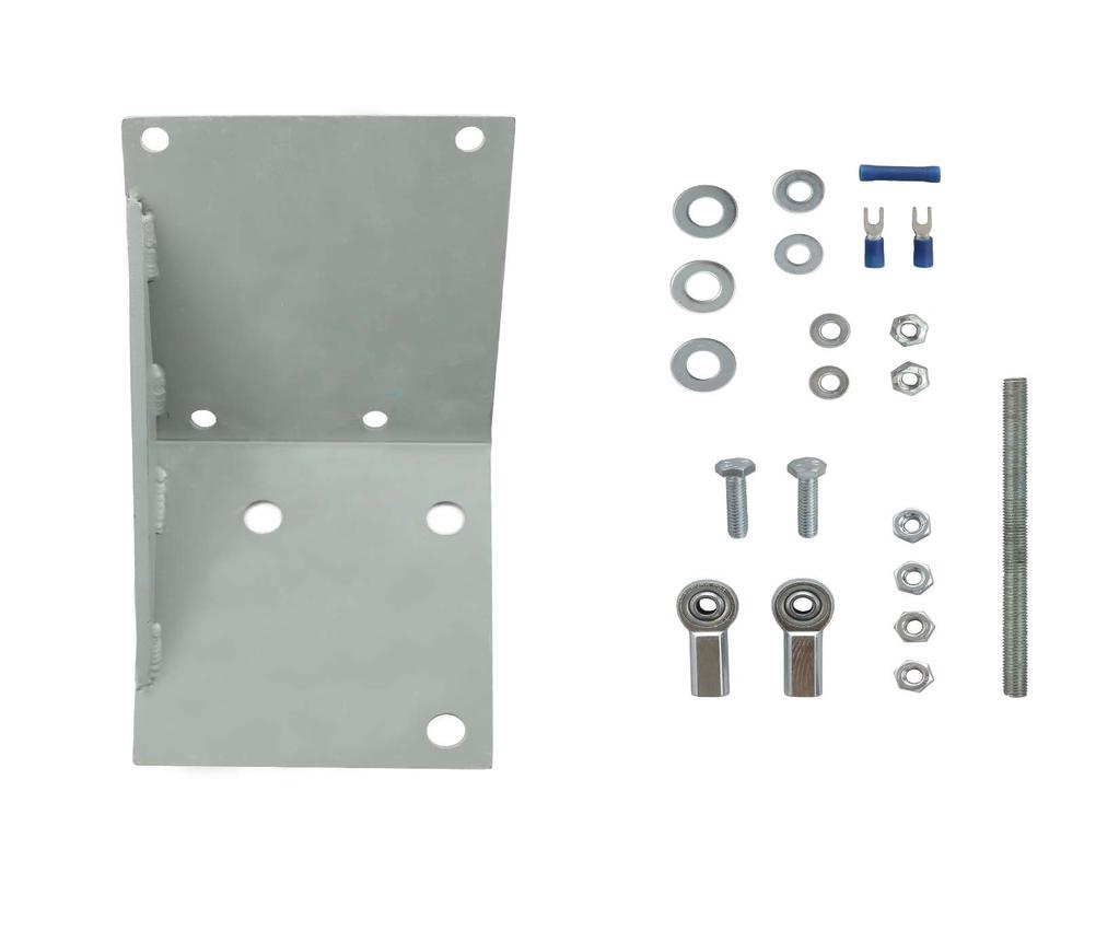
5 Governor Performance Adjustments 1.Rotate the Gain adjustment clockwise until instability develops. Gradually move the adjustment counter clockwise until stability returns. Move the adjustment 1/8 of a turn further counter clockwise to insure stable performance. 2. Rotate the STABILITY adjustment clockwise until instability develops. Gradually move the adjustment counter clockwise until stability returns. Move the adjustment 1/8 of a turn further counter clockwise to insure stable performance. 3. Gain and stability adjustments may require minor changes after engine load is applied. Normally adjustments made under no load conditions achieve satisfactory performance. If instability cannot be eliminated, or further performance improvements are required, refer to the Trouble Shooting Sections of the Speed Control Unit or Actuator publications. 4. Apply full load to the generator set. If it will not carry full load, stop the engine and shorten the linkage rod by turning the ball bearing rod ends in. Repeat the load test. It may be necessary to back out the maximum fuel stop screw on the operating and/or the shut off levers until full load is reached. Parts for Complete Set-up ITEM DESCRIPTION QUANITY KT101 Installation Kit 1 ADC120S-12 or 24 Electronic Actuator 1 ESD5111 Controller 1 MSP6718 or MSP6724 Mag-Pick-up 1 Options TP501 5K-1 Turn Potentiometer 1 EEG6500 Digital Controller Replacement for the ESD KT101 Components Part Number Description Quantity BK110 Actuator Bracket 1 HW M x 20 Bolt 3 HW M10 Lock-Washer 3 HW M10 Flat Washer 3 HW ¼-20 Hex Nut 2 HW ¼-20 Lock Nut 2 RD102 (cut to fit) ¼-28 x 12 plated linkage rod 1 BR200 ¼-28 Bearing End 2 HW /4-20 x 1 Bolt 2 HW ¼ Lock Washer 2 HW ¼ Flat Washer 2 HW ¼ -28 Nut 2 EC Solderless Spade Connector 2 EC Solderless Splice Connector 1
6 SR103 11/16 Spacer 3 HW ¼-20 x 1.5 Bolt 1 HW ¼-20 x 2.5 Bolt 1 O.E.M. Part Idling Spring, Mechanical Governor 1 O.E.M. Part Governor Spring, Mechanical Governor 1 KT101 Parts Illustration
7
KT230 Series Caterpillar 3406 Governor System Installation Kit
 KT230 Series Caterpillar 3406 Governor System Installation Kit 30 Years Strong! Introduction The KT230 Series Governor System Installation Kit provides the necessary brackets and hardware to install a
KT145 Series John Deere 6076 with Nippondenso Inj. Pump
 KT145 Series John Deere 6076 with Nippondenso Inj. Pump 30 Years Strong! Introduction The KT145 Series Governor System Installation Kit provides the necessary brackets and hardware to install a GAC precise
ENGINE GOVERNING SYSTEMS
 ENGINE GOVERNING SYSTEMS ESD5400 Series Speed Control Unit INSTALLATION The speed control unit is rugged enough to be placed in a control cabinet or engine mounted enclosure with other dedicated control
ESD5500E Series Speed Control Unit
 ESD5500E Series Speed Control Unit 1 SPECIFICATIONS INTRODUCTION PERFORMANCE Isochronous Operation ± 0.25% or better Speed Range / Governor 1-7.5 KHz Continuous Speed Drift with Temperature ±1% Maximum
ESD5100 Series Speed Control Unit PART NUMBER ESD5120 ESD (127)
") ESD5100 Series Speed Control Unit 1 INTRODUCTI The ESD5100 Series speed control unit is an all electronic device designed to control engine speed with fast and precise response to transient load changes.
ESD5100 Series Speed Control Unit 1 INTRODUCTI The ESD5100 Series speed control unit is an all electronic device designed to control engine speed with fast and precise response to transient load changes.
ESD5550 / 5570 Series Speed Control Units
 ESD5550 / 5570 Series Speed Control Units 1 The speed control unit is rugged enough to be placed in a control cabinet or engine mounted enclosure with other dedicated control equipment. If water, mist,
EDG6000 Electronic Digital Governor
 INTRODUCTION GAC s digital governor is designed to regulate engine speed on diesel and gaseous fueled engines. When paired with a GAC actuator the EDG is a suitable upgrade for any mechanical governor
10V. the rack of the oil pump must be on the
 P.E.D 20.. ESG2002 series ELECTRONIC GOVERNOR INSTRUCTION A1000C-W ELECTROMAGNETIC ACTUATOR Before inst al l el ectromag neti c, p lea se inspect that the rack of the oil pump shouldn' t be stuck in any
PED 5000 ELECTRIC ACTUATOR
 ENGINE GOVERNING SYSTEMS PRODUCT INFORMATION BULLETIN JAN 2002 PED 5000 ELECTRIC ACTUATOR INTRODUCTION The PED 5000 electric actuator is a rotatory output, linear torque, proportional servo. This electromechanical
ESD-5500E Series - Speed Control Unit
 ESD-5500E Series - Speed Control Unit INTRODUCTION The ESD-5500E Series speed control unit is an all electronic device designed to control engine speed with last and precise response to transient load
IGA225 Integrated Governor & Actuator
 INTRODUCTION GAC s integrated digital governor and actuator is designed to regulate engine speed on diesel and gaseous fueled engines. The IGA is a suitable upgrade for any mechanical governor system that
Installation Manual Installation Kit. for EPG 1712/1724 Electric Actuator on the Caterpillar D3406 Engine. Manual 54086
 Installation Manual 8924-600 Installation Kit for EPG 1712/1724 Electric Actuator on the Caterpillar D3406 Engine Manual 54086 DEFINITIONS This is the safety alert symbol. It is used to alert you to potential
Big Block Installation
 Factory Five Racing, Inc. Big Block Installation 427 Shown here with fuel injection. 1 These instructions are designed to supplement the assembly manual where the assembly process is different from the
IMO-517 (7027) ISSUE 3/97 ERA12, 25, 50, 83, 125, 167, 208 AND 250 ELECTRIC ACTUATORS INSTALLATION, MAINTENANCE AND OPERATING INSTRUCTIONS
 ISSUE 3/97 ERA12, 25, 50, 83, 125, 167, 208 AND 250 ELECTRIC ACTUATORS INSTALLATION, MAINTENANCE AND OPERATING INSTRUCTIONS") ERA12, 25, 50, 83, 125, 167, IMO-517 (7027) ISSUE 3/97 208 AND 250 ELECTRIC ACTUATORS INSTALLATION, MAINTENANCE AND OPERATING INSTRUCTIONS 2 Table of Contents 1 GENERAL...........................................
ERA12, 25, 50, 83, 125, 167, IMO-517 (7027) ISSUE 3/97 208 AND 250 ELECTRIC ACTUATORS INSTALLATION, MAINTENANCE AND OPERATING INSTRUCTIONS 2 Table of Contents 1 GENERAL...........................................
EDG5500 Electronic Digital Governor With Quikset Display
 1 INTRODUCTION EDG5500 Electronic Digital Governor With Quikset Display GAC s EDG5500 digital governor is designed to regulate engine speed on diesel and gaseous-fueled engines. The EDG system is a suitable
EEG6500 Enhanced Electronic Governor
 1 2 INTRODUCTION GAC s EEG6500 digital governor is designed to regulate engine speed on diesel and gaseous-fueled engines. The EEG system is a suitable replacement for any mechanical governor system that
235/245400, , 28N
 Models 235/245400, 287000, 28N thru W, 310/312/313700 These carburetors have a fixed high speed main jet with adjustable idle, Fig 183. The different carburetors are identified as LMT 1 and up. The letters
Installation Manual Installation Kit. for EPG 1712/1724 Electric Actuator on the Caterpillar 3208 Engine. Manual (Revision A)
") Installation Manual 8924-608 Installation Kit for EPG 1712/1724 Electric Actuator on the Caterpillar 3208 Engine Manual 54092 (Revision A) DEFINITIONS This is the safety alert symbol. It is used to alert
Installation Manual 8924-608 Installation Kit for EPG 1712/1724 Electric Actuator on the Caterpillar 3208 Engine Manual 54092 (Revision A) DEFINITIONS This is the safety alert symbol. It is used to alert
EG3002. Electronic Engine Governor Controller User Manual
 EG3002 Electronic Engine Governor Controller User Manual Engine Start Smoke Limiting function & IDLE Speed Setting For External, Built-in, PT-Pump type and hydraulic drive actuators Newly added extreme
INSTALLATION INSTRUCTIONS FOR ELECTRIC CHOKE KIT P/Ns , S, &
 INSTALLATION INSTRUCTIONS FOR ELECTRIC CHOKE KIT P/Ns 45-224, 45-224S, & 745-224 INTRODUCTION: Congratulations on your purchase of a new electric choke kit from Holley! These kits can be used to convert
EPG 1712/1724 or 512/524 Electric Actuator Installation. Product Manual (Revision NEW) Original Instructions
 Original Instructions") Product Manual 54120 (Revision NEW) Original Instructions EPG 1712/1724 or 512/524 Electric Actuator Installation On the Robert Bosch Fuel Pump Replacing RQ, RS, or RSV Mechanical Governor 8924-867 Kit
Product Manual 54120 (Revision NEW) Original Instructions EPG 1712/1724 or 512/524 Electric Actuator Installation On the Robert Bosch Fuel Pump Replacing RQ, RS, or RSV Mechanical Governor 8924-867 Kit
DESCRIPTION & OPERATION
 HEADLIGHT DOORS 1998 ACCESSORIES & EQUIPMENT General Motors Corp. - Headlight Doors DESCRIPTION & OPERATION NOTE: Headlight Doors Module (HDM) may also be referred to as headlight opening door actuator
ESD-5550/5570 Series - Speed Control Unit
 ESD-5550/5570 Series - Speed Control Unit Table 1. Starting Fuel Control ESD-5550/5570 Series Speed Control Units Speed Ramping Single Element Speed Switch (Overspeed) 2 Element Speed Switch (Overspeed
ESD-5550/5570 Speed Control Unit. Manual
 Manual Doc.-No. : ESD-5550- Version : 1.0 Date of Issue : HUEGLI TECH Switzerland This document, and the information contained herein is the intellectual property of HUEGLI TECH. It is to be used only
ALR Series Electronic Linear Actuators
 1 The ALR Series Actuator is designed to replace the OEM equipped shut down solenoid. To properly install the ALR actuator, a precise measurement must be obtained from the removed OEM equipped shutdown
Installation Manual. Model T675A Engine Brakes. For Mack 6 Cylinder, 2 valve Head ENDT-673, 675, 676 & E6 Series Engines.
 Engine Brakes Installation Manual Model T675A Engine Brakes For Mack 6 Cylinder, 2 valve Head ENDT-673, 675, 676 & E6 Series Engines TecBrake P.O. Box 27822 Houston, Texas 77227 INSTALLATION MANUAL TECBRAKE
ESC2301. Universal Electronic Governor Controller Operation Manual
 ESC2301 Universal Electronic Governor Controller Operation Manual *Replaces most Woodward, Barber Colman & Cummins Speed Controls Features Smoke Limit Control, Idle Speed Control, 12V or 24V input Suitable
SECTION 4 - FUEL SYSTEMS AND CARBURETION
 SECTION - FUEL SYSTEMS AND CARBURETION FUEL SYSTEMS - - - - - - - - - - - - - - - - - - - - - - - - - - - - - - - - - - - - - - - - - - - - - - - - - - - - - - - - - - - - - -62 FUEL PUMP - - - - - - -
2000 Dodge Durango ACCESSORIES & EQUIPMENT' 'Power Windows - Dakota & Durango 2000 ACCESSORIES & EQUIPMENT. Power Windows - Dakota & Durango
 DESCRIPTION & OPERATION 2000 ACCESSORIES & EQUIPMENT Power Windows - Dakota & Durango A permanent magnet motor moves each of the power windows. A master switch on driver's door controls all windows and
225 SERIES ELECTRIC ACTUATOR
 Generator Control Specialists 48A Ainsdale Street Telephone: 0500 800 225 P.O. Box 30 West Chermside, Qld 4032 Facsimile: 3350 1654 Grange, Qld 4051 Australia Mobile: 0427 22 00 18 Australia email: info@powersystems.com.au
PH3 AIR INTAKE EMERGENCY SHUT-OFF VALVE WITH POWERGUARD SMART OVERSPEED LIMITER. Generic PH3 Truck Shut-Off Valve Kit.
 PH3 AIR INTAKE EMERGENCY SHUT-OFF VALVE WITH POWERGUARD SMART OVERSPEED LIMITER Generic PH3 Truck Shut-Off Valve Kit www.powerhalt.com INSTALLATION REQUIREMENTS & RECOMMENDATIONS: Prior to the installation,
Illustrated Parts List to
 TYPE NUMBERS 0101, 0102, 0106, 0108, 0109, 0115 through 0224, 0415, 0418, 0467, 0468, 0601 through 0683, 3101 through 3108, 3110 through 3163, 3167 through 3181. Illustrated Parts List Model Series 124700
RMK HANDLEBAR KIT P/N ; ; APPLICATION BEFORE YOU BEGIN KIT CONTENTS. Verify accessory fitment at Polaris.com.
 RMK HANDLEBAR KIT P/N 2883835; 2883836; 2883837 APPLICATION Verify accessory fitment at Polaris.com. BEFORE YOU BEGIN Read these instructions and check to be sure all parts and tools are accounted for.
ESCO EQUIPMENT SUPPLY COMPANY FORKLIFT JACK. Instruction Manual. Forklift Jack
 FORKLIFT JACK Instruction Manual 10885 Forklift Jack 1 Specifications Scissors Capacity Post Capacity 4 Tons 5 Tons Minimum-Maximum Scissors Height 2.5 to 16.7 Minimum-Maximum Post Height 16.4 to 28.5
TOYOTA RAV TRAILER WIRE HARNESS Section I Installation Preparation
 Section I Installation Preparation Part Number: 08921-42900 Kit Contents Item # Quantity Reqd. Description 1 1 Converter 2 1 Wire harness 3 1 Sub wire harness No.1 4 2 Plastic Tie (300mm) 5 21 Plastic
BX88175 Installation Instructions ToadStop II Vacuum Brake System
 BX88175 Installation Instructions ToadStop II Vacuum Brake System Serial No. Customer supplied tools & supplies Utility knife, 12VDC tester, drill & bits: (1/8", 1/4", 5/8 ), ¼ socket drive bit, punch,
M Damper Mount Linkage Kit Installation. Item Description Quantity Item Description Quantity Nuts 2
 FANs 268.1, 1628.3 Installation Bulletin M9000-150 Issue Date 0796 M9000-150 Damper Mount Linkage Kit Installation 21 18 19 20 2 22 17 2 4 3 2 15.5 393.7 1 17 16 15 11 13 12 8 9 10 2 5 Note: Damper mount
Bulletin 1494C Cable Operated Disconnect Switch Kit (600A) Installation Instructions (Cat 1494C- _ Series 2 : 600A)
 Installation Instructions (Cat 1494C- _ Series 2 : 600A)") Bulletin 494C Cable Operated Disconnect Switch Kit (600A) Installation Instructions (Cat 494C- _ Series : 600A) ATTENTION: To prevent electrical shock, disconnect from power source before installing or
Bulletin 494C Cable Operated Disconnect Switch Kit (600A) Installation Instructions (Cat 494C- _ Series : 600A) ATTENTION: To prevent electrical shock, disconnect from power source before installing or
GPS AutoSteer System Installation Manual
 GPS AutoSteer System Installation Manual Supported Vehicles Case IH Vehicles Case 2577 Combines Case 2588 Combines Accuguide Ready PN: 602-0233-01-A LEGAL DISCLAIMER Note: Read and follow ALL instructions
Product Description. Product Numbers. Warning/Caution Notations. Required Tools. Wiring. Prerequisites
 Document No. 155-302N VE 598 Electronic Flowrite Valve Field Assembly Product Description The VE 598 Electronic Valve Assemblies consist of an electronic actuator, linkage kit, and a valve body assembly.
Installation Kit. Product Manual (Revision NEW) Original Instructions
 Original Instructions") Product Manual 54050 (Revision NEW) Original Instructions 8924-606 Installation Kit for EPG 1712/1724 Electric Actuator on the Cummins VT/VTA-1710 GS Engines Installation Manual DEFINITIONS This is the
Product Manual 54050 (Revision NEW) Original Instructions 8924-606 Installation Kit for EPG 1712/1724 Electric Actuator on the Cummins VT/VTA-1710 GS Engines Installation Manual DEFINITIONS This is the
Florham Park, NJ USA Call (ASCO) for sales or service
 for sales or service") Operator s Manual 7000 Series ATS Automatic Transfer Switches D design, 30 through 230 A DANGER is used in this manual to warn of a hazard situation which, if not avoided, will result in death or serious
Operator s Manual 7000 Series ATS Automatic Transfer Switches D design, 30 through 230 A DANGER is used in this manual to warn of a hazard situation which, if not avoided, will result in death or serious
EG1069X. Generator Electronic Governor Controller Operation Manual
 EG1069X Generator Electronic Governor Controller Operation Manual Smoke Limit Controller Compatible with Barber Colman Dyn1-1069X series *Use for reference purpose only and not a genuine Barber Colman
CARBURETION. Carburetor Identification. Models , , , , , , , , , , ,
 Carburetor Identification Models 110400, 110600, 111400, 111600, 113400, 120400, 120600, 121400, 121600, 122600, 123400, 123600 Models 28S700, 311700 Service Carburetor Briggs & Stratton/Walbro LMS Models
ATB Series - Integral Throttle Body Actuators
 ATB Series - Integral Throttle Body Actuators INTRODUCTION Low-Cost, Maintenance Free, Compact Design Various Bore Sizes Available (25-85mm) Precise, Real-Time Engine Speed Control Flexible Design for
Installation Manual. Model T680A/B Engine Brakes. For Mack 6 Cylinder, 4 Valve Head E6 and E7 Series Engines. Engine Brakes
 Engine Brakes Installation Manual Model T680A/B Engine Brakes For Mack 6 Cylinder, 4 Valve Head E6 and E7 Series Engines TecBrake P.O. Box 27822 Houston, Texas 77227 INSTALLATION MANUAL TECBRAKE T680A
Service Instruction. Introduction of fuel injection pumps with tight governor control. Fig 1
 Service Instruction Note DIESEL SEP 2002 Based on UK DT319 (EN) SIN 508 DPG PUMPS (DPA) EQUIPMENT: SUBJECT: Pumps 3230F560T, 3349F250T, 3340F260T, 3260F530T and 3340F280T fitted to gen set and constant
ANDCO Eagle Actuator Instruction Manual
 ANDCO Actuators ANDCO Eagle Actuator Instruction Manual The information contained in this manual is essential to safe, successful, long term operation of your Andco Eagle Linear Actuator. Read and follow
Installation Items: Cruise Module
 Installation Items: Rostra 250-1223, Electronic Cruise Control System (ECCS) includes the cruise module, harness, cruise cable, cruise module mounting bracket, cruise cable mounting bracket and hardware
1991 TRANSMISSION SERVICING Automatic Transmission. Mitsubishi: Eclipse, Galant, Mirage, Montero, Pickup, Precis, 3000GT
 Article Text ARTICLE BEGINNING 1991 TRANSMISSION SERVICING Automatic Transmission Mitsubishi: Eclipse, Galant, Mirage, Montero, Pickup, Precis, 3000GT IDENTIFICATION MITSUBISHI AUTOMATIC TRANSMISSION APPLICATIONS
Mid Size Traction Unit
 FORM NO. 3319 398 ProLine Mid Size Traction Unit 14 H.P. Kohler Gear Drive Model No. 30177 695101 Thru 696000 Parts Catalog 3319 398 ORDERING REPLACEMENT PARTS To order replacement parts, please supply:
Banks Brake. with installation instructions EXHAUST BRAKE SYSTEM Dodge 5.9L Cummins (12-valve) Turbo-Diesel Pickups with Manual Transmissions
 Turbo-Diesel Pickups with Manual Transmissions") OWNERS MANUAL with installation instructions Banks Brake EXHAUST BRAKE SYSTEM 1994-98 Dodge 5.9L Cummins (12-valve) Turbo-Diesel Pickups with Manual Transmissions THIS MANUAL IS FOR USE WITH SYSTEMS 55217
OWNERS MANUAL with installation instructions Banks Brake EXHAUST BRAKE SYSTEM 1994-98 Dodge 5.9L Cummins (12-valve) Turbo-Diesel Pickups with Manual Transmissions THIS MANUAL IS FOR USE WITH SYSTEMS 55217
Powers TM Controls EA 338 Electronic Actuator
 Powers TM Controls Technical Instructions Document No. 155-136P25 EA 338-1 Description Features 24 Vac power supply. The s are used with floor mount linkage kits to operate dampers in HVAC installations.
DYNA Power Control Manual For Plus 1, Plus 2, Plus 4 and Plus 6 Ft. Lb. Systems
 DYNA Power Control Manual For Plus 1, Plus 2, Plus 4 and Plus 6 Ft. Lb. Systems General Information... 2 Installation... 3 Calibration and Adjustments... 5 Maintenance Troubleshooting... 6 Plus 1 & Plus
ALR-190-Series Integral Actuator
 ALR-190-Series Integral Actuator Introduction The ALR-190 Series Integral Actuator is designed to mount integral to various injection Pumps of small engines. No external linkage or brackets are required
PARTS LIST. Craftsman 5.5 HP Snow Thrower Model
 24 Craftsman 5.5 HP Snow Thrower Model 24.88355 1. 31-2635 Snow Removal Tool Mount 2. 684-0405 Impeller Assembly, 12 Dia. 3. 10-034 Hex Screw, 3/8-16, 1.5, Gr5 4. 10-0451 Bolt, Carriage, 5/16-18,.50 Gr1
DRIVE AXLE Volvo 960 DESCRIPTION & OPERATION AXLE IDENTIFICATION DRIVE AXLES Volvo Differentials & Axle Shafts
 DRIVE AXLE 1994 Volvo 960 1994 DRIVE AXLES Volvo Differentials & Axle Shafts 960 DESCRIPTION & OPERATION All 960 station wagon models use type 1041 rear axle assembly. All 960 4-door models use type 1045
PRODUCT SERIES: DPG-2100
 Service Information PRODUCT SERIES: DPG-2100 DYNA Programmable Governor for Isochronous Generators Calibration and Troubleshooting for DPG-2101, DPG-2102, DPG-2103, DPG-2104 DPG-2100 The DPG-2100 governors
with discrete output (Overspeed) with auxiliary input (Synchronizer and Load Sharing)
 with auxiliary input (Synchronizer and Load Sharing)") Document: Digital Speed Governor Versions SDG-25 SDG-35 with discrete output (Overspeed) with auxiliary input (Synchronizer and Load Sharing) Integrated Heatsink Programming and Diagnostic Port Mode and
Document: Digital Speed Governor Versions SDG-25 SDG-35 with discrete output (Overspeed) with auxiliary input (Synchronizer and Load Sharing) Integrated Heatsink Programming and Diagnostic Port Mode and
Mfg. No:
 Parts Manual Mfg. No: 220707-0142-99 Copyright 2017 Briggs and Stratton. All Rights reserved 22-Jun-2017 Model Components Table Of Contents Page Blower Hsg, Sump, Oil Fill.............................................................................
Use Installation Procedure 1 when the crankshaft has NOT been rotated from the original position.
 2001 Blazer 4WD Applies to: 4.3L Report a problem with this article Removal Procedure Notice: There are two procedures available to install the distributor. Use Installation Procedure 1 when the crankshaft
PARTS MANUAL. RGV6100/6101 Generators. Models. PUB-GP1201A Rev. 12/99
 PARTS MANUAL Models RGV6100/6101 Generators PUB-GP1201A Rev. 12/99 RGV6100 & RGV6101-2 - '99-12 GROUP INDEX Group Name Page GENERATOR GROUP - RGV6100... 4 GENERATOR GROUP - RGV6101... 6 FRAME for RECOIL
LIPPERTCOMPONENTS, INC.
 LIPPERTCOMPONENTS, INC. SCHWINTEK INWALL SLIDEOUT SYSTEM OPERATION AND SERVICE MANUAL Contents I. Controls 1-1 System components 1 1-1A versions C1 & C2 2 1-2 Motor wiring harness connections 3 1-3 Extend
CIRRUS AIRPLANE MAINTENANCE MANUAL
 POWER CONTROL. DESCRIPTION This section describes those components which furnish a means of controlling engine power. Engine controls for the airplane include the following: control quadrant, throttle
Dodge Cummins Positive Air Shutoff
 1998-2002 24V 5.9 Dodge Cummins Positive Air Shutoff (I-00181) 1 INSTALL MANUAL 1998.5-2002 5.9 Dodge Cummins Positive Air Shutoff P/N# 1036719 P/N# 1036719-M UPLEASE READ ALL INSTRUCTIONS BEFORE INSTALLATION
PARTS MANUAL. RGV12000/12100 Generator. Model. PUB-GP1420 Rev. 12/01
 PARTS MANUAL Model RGV12000/12100 Generator PUB-GP1420 Rev. 12/01 Copyright 2001 Robin America, Inc. GROUP INDEX Group Name Page GENERATOR... 4 PIPE FRAME... 6 CONTROL BOX... 8 2-WHEEL ASSY.... 12 4-WHEEL
Oregon Fuel Injection
 Cummins PT Fuel Pump Diagnostic No Start, with no smoke 1. This could be caused by the fuel pump not turning or a seized gear pump. Remove the fuel supply hose and the fuel inlet fitting from the gear
Plantinum Series Control Installation Instructions Standard, Billet and Arched handles
 715 Center Street Grayslake IL 60030 P: 847-752-2700 F: 847-752-2415 Plantinum Series Control Installation Instructions Standard, Billet and Arched handles Thank you for choosing Livorsi Marine controls.
IGNITION TIMING (GASOLINE)
") IGNITION TIMING (GASOLINE) 4-CYLINDER IGNITION TIMING 2.5L (VIN E) 1. Set parking brake, block drive wheels and place transmission in Neutral or Park. Warm engine to normal operating temperature. Turn
IGNITION TIMING (GASOLINE) 4-CYLINDER IGNITION TIMING 2.5L (VIN E) 1. Set parking brake, block drive wheels and place transmission in Neutral or Park. Warm engine to normal operating temperature. Turn
Illustrated Parts List to
 Illustrated Parts List Model Series TYPE NUMBERS 0111 through 0199, 0200 through 0213, 0300 through 0353, 1345,1353, 2035 through 2073, 2135 through 2174, 4001 through 4090, 5001, 5005, 5006, 5035 through
62 Deck Idler Kit High Speed
 Part No. 00 FORM NO. -899 6 Deck Idler Kit High Speed For Model 70 Serial No. 99000 to 99000 For Model 7 Serial No. 9900 to 99000 INSTALLATION INSTRUCTIONS Loose Parts Note: Use the chart below to identify
PRODUCT SAFETY NOTICE
 PRODUCT SAFETY NOTICE Congratulations. This vehicle has been equipped with a Firestone air suspension system. This suspension will enhance the vehicle s handling when loaded, however, the vehicle s performance
Distributor Replacement (HVS)
") 1 of 8 3/3/2018, 3:02 PM 1998 Chevrolet K Pickup - 4WD Chevy Pickup, GMC Pickup, Suburban, Tahoe, Yukon VIN C/K Service Manual Engine Engine Electrical Repair Instructions Document ID: 207477 Distributor
1 of 8 3/3/2018, 3:02 PM 1998 Chevrolet K Pickup - 4WD Chevy Pickup, GMC Pickup, Suburban, Tahoe, Yukon VIN C/K Service Manual Engine Engine Electrical Repair Instructions Document ID: 207477 Distributor
Illustrated Parts List to
 Illustrated Parts List Model Series 124800 to 124899 FORM MS-2436-9/94 REPLACES FORM MS-2436-10/93 FILE IN SECT. 2 OF SERVICE MANUAL 124800 to 124899 TYPE NUMBERS 0106, 0206 through 0284, 0406 through
UNIVERSAL ATOMIC DIESEL MODEL (16 H.P.) PARTS MANUAL. Universal Motors
 PARTS MANUAL. Universal Motors") UNIVERSAL ATOMIC DIESEL MODEL 20 5416 (16 H.P.) PARTS MANUAL Universal Motors This copy of the Universal Motors Owners Manual has been re-created using images computer scanned from a manual rather than
UNIVERSAL ATOMIC DIESEL MODEL 20 5416 (16 H.P.) PARTS MANUAL Universal Motors This copy of the Universal Motors Owners Manual has been re-created using images computer scanned from a manual rather than
Champion Reverse Gear Harley-Davidson Six Speed Transmissions for FLH 2007 to 2008 and Softail 2007 up
 Champion Reverse Gear s for FLH 2007 to 2008 and Softail 2007 up (Cable or Hydraulic Clutch) Installation Instructions Revision 11 Champion Motorcycle Accessories International, Inc. dba Champion Sidecars
UNIVERSAL ELECTRA-STEER FOR 2 COLUMN 220w Plain w Polished w Plain w Polished
 UNIVERSAL ELECTRA-STEER FOR 2 COLUMN 220w Plain 8052810 220w Polished 8052610 360w Plain 8052780 360w Polished 8052760 Full refund will NOT be granted to any kits that are damaged, scratched, or altered
#TL T EA888 GEN 3 FUELING SYSTEM/ INSTALLATION INSTRUCTIONS
 #TL100069 2.0T EA888 GEN 3 FUELING SYSTEM/ INSTALLATION INSTRUCTIONS Notes: These instructions were written for a North American specification MkVII GTI. Other models, like the Golf R, are similar. When
REMOVAL & INSTALLATION
 REMOVAL & INSTALLATION Removal 1. Center steering wheel. Disconnect negative battery cable. Remove steering coupling shield (if equipped). Disconnect steering shaft at flexible coupling or pot joint. Note
AUTOMATIC CLUTCH Models
 AUTOMATIC CLUTCH 1940 Models Source of this material is from 1940 Series, Issue 4, January 1940 Hudson Service Magazine AUTOMATIC CLUTCH 1940 MODELS The automatic clutch installation and adjustment procedure
CHEETAH Competition Manual Valve Body - (PRN321) Part #27253
 Part #27253") 1535 Owens Road, Jacksonville, FL 32218 Phone 904-741-4850 * Fax 904-741-4853 CHEETAH Competition Manual Valve Body - (PRN321) Part #27253 Turbo Hydro 200-1976-Up FIRST, READ INSTRUCTIONS CAREFULLY, THEN
1535 Owens Road, Jacksonville, FL 32218 Phone 904-741-4850 * Fax 904-741-4853 CHEETAH Competition Manual Valve Body - (PRN321) Part #27253 Turbo Hydro 200-1976-Up FIRST, READ INSTRUCTIONS CAREFULLY, THEN
Champion Reverse Gear Harley-Davidson Six Speed Transmissions for FLH 2009 Up
 Champion Reverse Gear s for FLH 2009 Up (Cable or Hydraulic Clutch) Installation Instructions Revision 2 Champion Motorcycle Accessories International, Inc. dba Champion Sidecars 11841 Monarch Street,
CRUISE CONTROL SYSTEM
 CRUISE CONTROL SYSTEM 1998 Pontiac Bonneville 1998 ACCESSORIES & EQUIPMENT General Motors Corp. - Cruise Control System Buick; LeSabre Oldsmobile; Eighty Eight, LSS & Regency Pontiac; Bonneville * PLEASE
***FOR COMPETITION USE ONLY as per US EPA regulations *** Factory Pipe Bill of Materials Kawasaki Ultra 150 Triple Pipe
 ***FOR COMPETITION USE ONLY as per US EPA regulations *** Factory Pipe Bill of Materials Kawasaki Ultra 150 Triple Pipe Item Qty Part Number Part Description 1 1 COMASM0947 Ultra 150 PTO Chamber assembly
WPS-104 Heater Installation Instructions For 500EFI, 700 XP, & Crew Applications
 WPS-104 Heater Installation Instructions For 500EFI, 700 XP, & Crew Applications ORDER OF INSTALLATION FOR A COMPLETE ENCLOSURE OF A RANGERWARE WPS (Weather Protection System) IS AS FOLLOWS: 1. Heater
TUNE-UP - 4-CYL Jeep Cherokee IDENTIFICATION ENGINE IDENTIFICATION TUNE-UP NOTES TESTING ENGINE COMPRESSION SPARK PLUGS
 TUNE-UP - 4-CYL 1988 Jeep Cherokee 1988 Jeep 4 Tune-Up TUNE-UP All Models IDENTIFICATION ENGINE IDENTIFICATION Engine can be identified by the 4th character of the Vehicle Identification Number (VIN).
STEERING AND OTAS SYSTEMS
 STEERING AND OTAS SYSTEMS SERVICE TOOLS Description Part Number Page DIAGNOSTIC HARNESS... 529 036 188... 10 FLUKE 115 MULTIMETER... 529 035 868... 10 11 SERVICE PRODUCTS Description Part Number Page XPS
PRXB EXHAUST BRAKE HIGH PERFORMANCE
 HIGH PERFORMANCE PRXB EXHAUST BRAKE C44059, C4406, C44063, C44065 APPLICATION 994-2002 DODGE RAM AUTOMATIC TRUCKS EQUIPPED WITH 47RE TRANSMISSIONS WITH 5.9L, 24 VALVE CUMMINS DIESEL ENGINES GETTING STARTED
On all settings above 100 horsepower the following precautions should be observed:
 ELECTRONIC FUEL INJECTED 5.0 COYOTE PLATE SYSTEM INSTALLATION INSTRUCTIONS Congratulations on the purchase of your Nitrous Express Coyote Plate system. Nitrous Express utilizes only the highest quality
EEG6550 Enhanced Electronic Governor
 1 2 INTRODUCTION Computer SPECIFICATIONS PERFORMANCE Isochronous Operation ± 0.25% Speed Range / Governor Idle Adjust Droop Range Speed Trim Supply Polarity Power Consumption Speed Sensor Signal Actuator
PRXB EXHAUST BRAKE MAXIMUM EXHAUST FLOW DESIGN
 MAXIMUM EXHAUST FLOW DESIGN PRXB EXHAUST BRAKE C44072/C44073/C44074/C44075/C44076 APPLICATION: 994-2002 DODGE RAM TRUCKS W/5.9L CUMMINS DIESEL ENGINES WITH MANUAL & AUTOMATIC TRANSMISSIONS STOCK DODGE
1999 Toyota RAV ACCESSORIES & EQUIPMENT Cruise Control Systems - RAV4
 1999 ACCESSORIES & EQUIPMENT Cruise Control Systems - RAV4 DESCRIPTION WARNING: Deactivate air bag system before performing any service operation. See AIR BAG RESTRAINT SYSTEMS article. DO NOT apply electrical
Florham Park, NJ USA Call (ASCO) for sales or service
 for sales or service") Operator s Manual 4000 Series ATS Automatic Open-Transition Transfer Switches D design 30 230A, J design 260 600A, H-design 800 1200A, G-design 1600 4000A, F-design 4000A DANGER is used in this manual
Operator s Manual 4000 Series ATS Automatic Open-Transition Transfer Switches D design 30 230A, J design 260 600A, H-design 800 1200A, G-design 1600 4000A, F-design 4000A DANGER is used in this manual
LAKEWOOD/QUICKTIME SAFETY BELLHOUSING INSTALLATION INSTRUCTIONS
 LAKEWOOD/QUICKTIME SAFETY BELLHOUSING INSTALLATION INSTRUCTIONS Congratulations on your purchase of the finest quality steel bellhousing available today. 100% Manufactured in the USA! Please understand
EG1065X. Compatible with Barber Colman* Dyn1-1065X series * Use for reference purpose only and not a genuine Barber Colman product.
 EG1065X Generator Electronic Governor Controller Operation Manual Compatible with Barber Colman* Dyn1-1065X series * Use for reference purpose only and not a genuine Barber Colman product. Headquarters
ENGINE ADJUSTMENTS. Remote Controls
 ENGINE ADJUSTMENTS Remote Control Wire Travel The remote control wire should measure 2.25 (54 mm) when extended outside the casing (Figure 2). After installation, the travel of the remote control wire
Mid Size Traction Unit
 FORM NO. 3318 701 ProLine Mid Size Traction Unit 18 H.P. Kohler Gear Drive Model No. 30183 790001 & Up Parts Catalog 3318 701 ORDERING REPLACEMENT PARTS To order replacement parts, please supply: the part
S/N 1H019H - 1H310H Page 1 of 33 46" Cutting Deck Assembly
 1180 S/N 1H019H - 1H310H Page 1 of 33 46" Cutting Deck Assembly 1180 S/N 1H019H - 1H310H Page 2 of 33 46" Cutting Deck Assembly 1 17982 1 S Reinforcement Spindle Plate 2 618-0430 1 S Spindle Assembly w/
CHAPTER 4 GOVERNORS AND LINKAGE
 CHAPTER 4 S AND LINKAGE Main Menu GENERAL INFORMATION Tecumseh 4 cycle engines are equipped with mechanical type governors. The governor s function is to maintain a R.P.M. setting when engine loads are
Bulletin 1494V Variable Depth, Flange Operated Disconnect Switch Kits for 400 and 600 Amperes (Series A) Switches
 Switches") Bulletin 494V Variable Depth, Flange Operated Disconnect Switch Kits for and Amperes (Series A) Switches ATTENTION: To prevent electrical shock, disconnect from power source before installing or servicing.
Bulletin 494V Variable Depth, Flange Operated Disconnect Switch Kits for and Amperes (Series A) Switches ATTENTION: To prevent electrical shock, disconnect from power source before installing or servicing.