HYDRAULIC CYLINDER HYC
|
|
|
- Clemence Wilkinson
- 6 years ago
- Views:
Transcription

1 HYDRAULIC CYLINDER HYC
2 INTRODUCTION The hydraulic cylinder, as a link between hydraulic control and the machine, is suitable for use in many areas of industry, such as pressing and joining applications, the chemical industry or tool making. Hydraulic cylinders can also be used without a problem in areas having extremely high or low ambient temperatures. The Hydropa HYKS series of hydraulic cylinders exhibit a sturdy welded/bolted construction with honed and seamless cylinder barrels and ground, precision hard chromeplated piston rods that are delivered with a prime coating as a standard feature. We are also happy to manufacture customized hydraulic cylinders. In order for us to submit an offer to meet your needs, please provide any special dimensions and requirements for the hydraulic cylinder along with your inquiry. When designing hydraulic cylinders, the permissible collapse load for the particular stroke must be taken into consideration! If you cannot glean this information from the documents at your disposal, we would be happy to take care of this for you. TABLE OF CONTENTS General Operating instructions Basis of calculations for hydraulic cylinders Technical data Mounting methods Product key Cylinder (dimensions) - HYC-...-G- / HYKS-...-S- (articulated / swivel eye) - HYC-...-B- (Flange at base) - HYC-...-K- (Flange at head) - HYC-...-M- (Trunnion) - HYC...-T- (Tangential feet) Piston rod eyes - GIHR-K / SA-K Page End position scan and linear measurement 18 Cylinder request form 19 2/20
3 GENERAL GENERAL CHARACTERISTICS Piston diameter: Perm. max. operating pressure: Test pressure: Piston speed: Temperature range: Mounting position: Damping adjustable: Distance measurement: MATERIALS Piston rod: Cylinder: Seals: 20MnV6 St52 NBR PTFE POM PU 40 to 200 mm 250 bar 300 bar 0,5 m/s to 4 m/s -30 C to +80 C any piston- 50 mm transducer or inductive proximity switch The seals are designed for use with hydraulic oils in accordance with DIN and DIN and a temperature range of -30 C to +80 C. Seals for other temperature ranges and operating media as well as for other cylinder and rod materials are available upon request. OPERATING PRESSURE Our hydraulic cylinders are subjected to a static pressure test before delivery. The operating pressure can be selected freely on the basis of the operating conditions and the required level of safety with reference to the test pressure. PORTS The oil ports are manufactured with standard metric fine thread or Whitworth pipe thread. FILTERING When the system is filled during operation, the hydraulic fluid must be filtered so that contamination with solids does not exceed the thresholds according to NAS 1638 Class 8 (Class 9 for 15μm and smaller) or ISO17/14. Finer filtration increases the lifetime of the equipment. Whatever the application, it must be ensured that the above limits are not exceeded. DIFFERENTIAL CYLINDER It must be ensured that differential cylinders have a free flow of hydraulic fluid from the piston rod end so that the pressure never exceeds the maximum operating pressure as a result of the pressure ratio. SAFETY REGULATIONS These instructions are intended for the safety work with hydraulic cylinders. They contain safety instructions that must be followed. The instructions must be available for all persons during their work with hydraulic cylinders. The instructions must always be complete and be in good readable condition. Only skilled workers, technicians and installers of machinery and equipment with hydraulic expertise are allowed to perform this work. Technical knowledge means that the personnel must - be able to read and completely understand technical specifications such as Circuit diagrams and productspecific design documents - have knowledge about function and construction of hydraulic components A qualified person is someone who has sufficient knowledge and is sufficiently familiar with the relevant provisions through technical training and experience that she/he - can assess the work assigned to her/him - can recognize potential hazards - is able to use necessary measures to eliminate risks - has repair and assembly knowledge VENTILATION Ventilation takes place at idling pressure through the base or rod-end oil port. Additional ventilation connections on the hydraulic cylinder can be provided upon customer request. 3/20
4 OPERATING INSTRUCTIONS STORAGE In order to ensure a long shelf life of the bearing surfaces and seals of hydraulic cylinders, and to protect them against corrosion, the piston rods should be retracted and the cylinders filled completely with oil. It is important to ensure that no air is trapped in the cylinder and that the connections are sealed airtight. The piston rod thread, the free rod end, and ball and socket joints should be coated lightly with anti-corrosion grease. If the cylinders are stored at fluctuating ambient temperatures, they must be protected with a pressure relief valve on each port end. After long periods of storage, pressure marks may occur at the seals, but these will disappear after the piston has been extended and retracted several times. MAINTENANCE Hydraulic cylinders are generally maintenance free. For heavy-duty use, make sure to lubricate the bearings, such as the articulated and swivel eyes as well as the trunnion. Seals and bearings are consumables. Once the internal or external leakage reaches an unacceptable level, we recommend that you replace the seals and bearings and check the cylinder for further wear. Of course we are always at your service to do this work for you. INSTALLATION During the installation of hydraulic cylinders the following points should be noted: - Before installing the hydraulic cylinder in the system, the type designation must be compared with the ordering data - Make sure to keep the hydraulic cylinder and the area around it clean - The operating fluid must be compatible with the sealing material - Pipes should be cleaned of dirt, scale, chips, and the like before installation - Never use lint-producing cloth or special paper for cleaning purposes - The hydraulic cylinders must be installed and operated without any radial forces or stress. These transverse forces put a strain on the piston and piston rod guide of the hydraulic cylinder and lead to a shorter lifetime and leakages or even destruction. COMMISSIONING Before commissioning, the hydraulic cylinder must be vented. At idle pressure, open the bleeder screw / base- and rod-end screw and let the air escape. When no more bubbles come forth from the oil, re-tighten the bleed screw / screw. ASSEMBLY AND DISASSEMBLY When seals are changed, all seals and guide elements in general should be replaced. The contact surfaces of metallic parts should be checked for any cracks or score marks. If they do not exhibit any signs of damage or abnormal wear, then they can be re-used. In order to disassemble the hydraulic cylinder, unscrew the rod guide (12) from the cylinder housing (7) using a hook wrench. Pull the rod (1) out of the cylinder housing (7). After removing the piston (3) by means of a hook wrench, all of the sealing elements (5, 6, 8, 9, 11, 13) and guide elements (4, 10) can now be replaced. Oil the seals lightly and slip on with the help of a roundpointed tool. Be sure to install the rod seal (11) and the scraper ring (13) in the right direction. Once all of the seal and guide elements have been replaced, insert the piston into the lubricated cylinder housing (7). Lubricate the thread of the rod guide (12) and screw in firmly into the cylinder housing (7). Mount the assembled cylinder on a test bench to check for proper functioning and leaks. 4/20


5 REPLACMENT PARTS When ordering spare parts, always include the imprinted order number, which is located to the right of the base-end connection (in reference to the piston rod). PLEASE NOTE : Installation, repair and commissioning of cylinders may be carried out only by trained specialist personnel with the necessary expertise. Hydropa assumes no liability for any damage resulting from installation, repairs and commissioning, which were not carried out or commissioned by Hydropa. Pos. Description Pos. Description 1 Cylinder tube 10 Piston rings 2 Piston rod 11 Rod rings 3 Cylinder head / Rod guide 12 Venting 4 Cylinder Base 13 Damping- and check valve 5 Hex nut 14 Scraper 6 Damping bush 15 O-Ring 7 Damping nut 16 Rod seal 8 O-Ring 17 Piston seal 9 Piston 5/20
6 BASIS OF CALCULATIONS FOR HYDRAULIC CYLINDERS Piston and ring surfaces / lifting and tractive forces Piston Rod A Piston area (cm 2 ) Ring area (cm 2 ) Theoretical compressive force at 210 bar (kn) Theoretical tractive force at 210 bar (kn) 22 8,765 18,41 12,566 26, ,409 13, ,477 28,30 19,635 41, ,456 19, ,994 44,09 31,172 65, ,268 32, ,361 72,16 50, , ,635 53, , ,21 78, , ,055 84, , ,89 122, , , , , ,67 153, ,27 75, ,34 122, ,30 201, , , , , ,82 254, ,38 131, ,68 191, ,03 314, ,73 160, ,46 EFFICIENCY FACTOR The values given in the table do not take into account the efficiency factor. Every hydraulic cylinder loses power due to the friction resistance of the sealing and guiding elements. Since the effect of these losses is different at different pressures, the following average values are anticipated as the efficiency factors: Efficiency factor Pressure (bar) Efficiency factor µ 0,85 0,9 0,92 0,97 6/20

![85, p = 60 bar [ 1 bar = 10 N/cm2 ] given: Hydraulic cylinder with d1 = 50 mm, d2 = 36 mm, Q = 12 l/min needed: Effective piston force (F) needed: Piston speed (v) extension: F = p * A * μ = 600](/docs-images/72/66974447/images/7-5.jpg "N/cm2 * ( π * ( 10 cm )2 / 4 ) * 0.85 = 40.055 N extension: v = Q 12.")
7 PISTON FORCES PISTON SPEED p = pressure A = effective piston surface F = effective piston force d1 = piston diameter d2 = piston rod diameter µ = efficiency factor of the cylinder Effective piston force: F = p * A * μ Q = volumetric flow rate A = effective piston surface v = piston speed Piston speed: v = Q / A example example given: Hydraulic cylinder with d1 = mm, d2 = 70 mm, μ = 0.85, p = 60 bar [ 1 bar = 10 N/cm2 ] given: Hydraulic cylinder with d1 = 50 mm, d2 = 36 mm, Q = 12 l/min needed: Effective piston force (F) needed: Piston speed (v) extension: F = p * A * μ = 600 N/cm2 * ( π * ( 10 cm )2 / 4 ) * 0.85 = N extension: v = Q cm = / min cm = 611 A ((π * (5cm) 2 ) min = 6,11 4 m min retraction: F = p * A * μ = 600 N/cm2 * ( π * ( ( 10 cm )2 - ( 7 cm )2 ) / 4 ) * 0.85 = N retraction: Q cm v = = 3 / min cm m = = 12,69 A ((π * (5cm) 2 ) ((π * (3,6cm) 2 ) min min /20
8 TECHNICAL DATA Buckling calculation The tables show the permissible stroke in mm at buckling stress (compressive stress) according to Euler with 3.5 times the safety factor and flexibly guided load. The calculation of buckling SK is carried out according to Euler, whereby in simplified terms the piston rod and tube can be regarded as a slender rod. SK = per. stroke length in mm E = modulus of elasticity 2,1 * 105 for steel in N/mm2 J = moment of area im mm4 4 d * π for circular cross-section = 64 Euler case 2 using articulated / swivel eye as an example SK = π2 * E * J - (A + add. meas.) F*S 2 F = compressive force in N/cm2 Euler case 3 using head flange as an example SK = A = measurement A of the piston rod eye, see pg. 17 S = 3.5 (safety factor) π2 * E * J F*S - (A + add. meas.) 0,707 per. stroke Mounting type articulated / swivel eye HYC-...-G/S-... (with measurement L and piston rod eye) Piston Piston rod Working pressure (bar) permissible stroke per. stroke Mounting type trunnion HYC-...-M-... (with measurement L and piston rod eye) Piston Piston rod Working pressure (bar) permissible stroke /20
9 Mounting type head flange HYC-...-K-... (with measurement L and piston rod eye) Piston Piston rod Working pressure (bar) permissible stroke per. stroke Mounting type base flange HYC-...-B-... (with measurement L and piston rod eye) Piston Piston rod Working pressure (bar) permissible stroke per. stroke Mounting type tangential feet HYC-...-T-... (with measurement D and piston rod eye) Piston Piston rod Working pressure (bar) permissible stroke per. stroke /20


10 MOUNTING METHODS Optional: Piston rod eye, fork head We also build other models according to customer specifications. basic cylinder HYC-... articulated eye, base end HYC-...-G-... swivel eye, base end HYC-...-S-... base flange HYC-...-B-... head flange HYC-...-K-... trunnion HYC-...-M-... tangential feet HYC-...-T /20
11 PRODUCT KEY HYDRAULIC CYLINDER SERIES: HYC HYC /... / MOUNTING TYPE G = articulated eye S = swivel eye K = head flange B = base flange M = trunnion T = tangential feet 2 PISTON DIAMETER 3 ROD DIAMETER... =piston rod material 20MnV6 (standard) 4 ROD DIAMETER (for synchronous cylinder only)... = piston rod material 20MnV6 (standard) 5 STROKE 6 OIL PORT THREAD no specification = pipe thread M = metric thread 7 TYPE OF MOUNTING ON PISTON ROD no specification = Piston rod thread GIHR-K = Piston rod eye,clampable SA-K = Swivel eye, clampable GK = Clevis, clampable 8 MEASURING SYSTEM BTL = linear transducer BES = inductive proximity swich 9 ADDITIONAL DISCLOSURES no specification = Standard SO = Sondermaße 10 SEALS C04 C06 C15 = sealing stick-slip-free with retaining function = same as C04, Material: viton fluoroelastomers* = Seals like customer information EXAMPLE HYC - G / 036 / GIHR-K SO - C *Viton is a registered trademark of DuPont Performance Elastomers 11/20
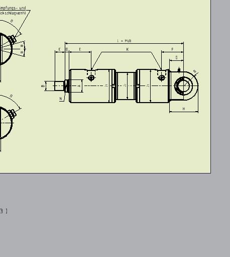
12 DIFFERENTIAL CYLINDER WITH ARTICULATED / SWIVEL EYE HYC-G Venting 60 Damping- and Checkvalve 60 S α α P O HYC-S C D E L + Stroke K F G R T B A J2 N O H Differential cylinder with articulated / swivel eye K Piston Piston T Weight (kg) Tilt GIHR-K, J Type rod A B C D E F G H 1 J 2 W-Tube N S Damping L O P R H11 angle SA-K, GK for each- (Standard) 0mm of stroke Metr. α (equipm.) stroke mm HYC-...-G/S-40/ M18 x 40 M16 x 1, G 3/8 175±1 2,5 3,6 0, , HYC-...-G/S-40/ ,5 3 3,7 1 HYC-...-G/S-50/ M22 x 3 7 1,3 50 M22 x 1, G 1/2 200± , HYC-...-G/S-50/ ,5 4 7,1 1,6 HYC-...-G/S-63/ M22 x 4 9,3 1,8 63 M28 x 1, G 1/2 225± , HYC-...-G/S-63/ ,5 4 9,5 2,3 HYC-...-G/S-80/ ,9 80 M35 x 1, G 3/4 M27 x 2 265± , HYC-...-G/S-80/ ,2 3,6 HYC-...-G/S-/ ,7 M45 x 1, G 3/4 M27 x 2 305± , HYC-...-G/S-/ ,8 HYC-...-G/S-/ ,4 M58 x 1, G 1 M33 x 2 350± , HYC-...-G/S-/ ,4 HYC-...-G/S-/ M65 x 1, G 1 M33 x 2 370± , HYC-...-G/S-/ HYC-...-G/S-160/ M80 x G 1 1/4 M42 x 2 415± , HYC-...-G/S-160/ HYC-...-G/S-180/ M x G 1 1/4 M42 x 2 478± , HYC-...-G/S-180/ HYC-...-G/S-200/ M110 x G 1 1/4 M42 x 2 500± , HYC-...-G/S-200/ /20
13 DIFFERENTIAL CYLINDER WITH BASE FLANGE Venting Damping- and Checkvalve C D E L+Stroke K F ß ß B A J2 He8 N S O P R G R Differential cylinder with base flange K Weight (kg) Piston Piston H GIHR-K, J Type rod A B C D E F G 1 J 2 W-Tube N O P S min. L R e8 R SA-K, GK Damping for each (Standard) 0mm of stroke Metr. 1 Hub (equipm.) stroke mm HYC-...-B-40/ M18 x 40 M16 x 1, , G 3/8 168±1 2,5 5,5 0, ,5 3, HYC-...-B-40/ ,5 3 5,6 1 HYC-...-B-50/ M22 x 3 9,8 1,3 50 M22 x 1, , G 1/2 193± ,5 3, HYC-...-B-50/ ,5 4 9,9 1,6 HYC-...-B-63/ M22 x 4 13,8 1,8 63 M28 x 1, , G 1/2 213± ,5 3, HYC-...-B-63/ , ,3 HYC-...-B-80/ ,5 2,9 80 M35 x 1, G 3/4 M27 x 2 254± HYC-...-B-80/ ,7 3,6 HYC-...-B-/ ,5 4,7 M45 x 1, G 3/4 M27 x 2 289± HYC-...-B-/ ,5 5,8 HYC-...-B-/ ,4 M58 x 1, G 1 M33 x 2 335± HYC-...-B-/ ,4 HYC-...-B-/ M65 x 1, G 1 M33 x 2 350± HYC-...-B-/ HYC-...-B-160/ M80 x G 1 1/4 M42 x 2 395± HYC-...-B-160/ HYC-...-B-180/ M x G 1 1/4 M42 x 2 449± HYC-...-B-180/ HYC-...-B-200/ M110 x G 1 1/4 M42 x 2 451± HYC-...-B-200/ /20

14 DIFFERENTIAL CYLINDER WITH HEAD FLANGE L + Stroke Venting 60 Damping- and Checkvalve 60 C D E K F V He8 B A J2 N S O P R1 G R U + 2xStroke T + Stroke Differential cylinder with head flange Type Piston Piston rod A B C D E F G H e8 J 1 J 2 W-Tube (Standard) K Metr. L N O P R R 1 S T U V min. GIHR-K, SA-K, GK Hub (equipm.) Damping Weight (kg) for each stroke mm of 0mm stroke 4,6 0,9 HYC-...-K-40/ M16 x 1, ,5 46, G 3/8 M18 x 1,5 145±1 2, ,5 3,5 9 10± HYC-...-K-40/ ,7 1 HYC-...-K-50/ ,7 1,3 50 M22 x 1, ,5 53, G 1/2 M22 x 1,5 165± ,5 3, ± HYC-...-K-50/ ,8 1,6 HYC-...-K-63/ ,8 63 M28 x 1, ,5 59, G 1/2 M22 x 1,5 180± ,5 3, ± HYC-...-K-63/ ,5 2,3 HYC-...-K-80/ ,5 2,9 80 M35 x 1, G 3/4 M27 x 2 215± ± HYC-...-K-80/ ,6 HYC-...-K-/ ,7 M45 x 1, G 3/4 M27 x 2 245± ± HYC-...-K-/ ,8 HYC-...-K-/ ,4 M58 x 1, G 1 M33 x 2 280± ± HYC-...-K-/ ,4 HYC-...-K-/ M65 x 1, G 1 M33 x 2 295± ± HYC-...-K-/ HYC-...-K-160/ M80 x G 1 1/4 M42 x 2 330± ± HYC-...-K-160/ HYC-...-K-180/ M x G 1 1/4 M42 x 2 383± ± HYC-...-K-180/ HYC-...-K-200/ M110 x G 1 1/4 M42 x 2 385± ± HYC-...-K-200/ /20
 Piston Piston rod R J Type A B C D E F G H 1 J 2 N S L O P e8 r U min. GIHR-K, W-Tube SA-K, GK Damping for each (Standard) 0mm of stroke Metr. Hub (equipm.) stroke mm HYC-...-M-40/22-.")
15 r DIFFERENTIAL CYLINDER WITH TRUNNION Venting 60 Damping- and Checkvalve 60 C D E L + Stroke K F E Re8 B A J2 S O P N H + Stroke 2 G D + Stroke U + 2xStroke Differential cylinder with trunnion K Weight (kg) Piston Piston rod R J Type A B C D E F G H 1 J 2 N S L O P e8 r U min. GIHR-K, W-Tube SA-K, GK Damping for each (Standard) 0mm of stroke Metr. Hub (equipm.) stroke mm HYC-...-M-40/ M16 x M18 x G 3/8 145±1 2,5 4,3 0, , HYC-...-M-40/ ,5 1,5 3 4,4 1 HYC-...-M-50/ M22 x M22 x 3 7,8 1, G 1/2 165± , HYC-...-M-50/ ,5 1,5 4 7,9 1,6 HYC-...-M-63/ M28 x M22 x 4 10,5 1, G 1/2 180± HYC-...-M-63/ ,5 1,5 4 10,7 2,3 HYC-...-M-80/ M35 x , G 3/4 M27 x 2 215± HYC-...-M-80/ ,5 5 20,2 3,6 HYC-...-M-/ M45 x 5 32,5 4, G 3/4 M27 x 2 245± HYC-...-M-/ ,5 6 33,5 5,8 HYC-...-M-/ M58 x , G 1 M33 x 2 280± , HYC-...-M-/ , ,4 HYC-...-M-/ M65 x G 1 M33 x 2 295± , HYC-...-M-/-... 1, HYC-...-M-160/ M80 x G 1 1/4 M42 x 2 330± , HYC-...-M-160/ HYC-...-M-180/ M x G 1 1/4 M42 x 2 383± , HYC-...-M-180/ HYC-...-M-200/ M110 x G 1 1/4 M42 x 2 385± , HYC-...-M-200/ /20
16 I DIFFERENTIAL CYLINDER WITH TANGENTIAL FEET Venting 60 Damping- and Checkvalve 60 C D E L + Stroke K F E R B A J2 H O P S G T + Stroke G D + Stroke U + 2xStroke Differential cylinder with tangential feet Type Piston Piston rod A B C D E F G H I J 1 J 2 W-Tube (Standard) K Metr. L N O P R S T U min. Hub GIHR-K, SA-K, GK (equipm.) Damping Weight (kg) HYC-...-T-40/ M16 x M18 x G 3/8 145±1 2,5 5,1 0, HYC-...-T-40/ ,5 1,5 3 5,2 1 HYC-...-T-50/ M22 x M22 x 3 9,1 1, G 1/2 165± HYC-...-T-50/ ,5 1,5 4 9,2 1,6 HYC-...-T-63/ M28 x M22 x 4 12,3 1, G 1/2 180± HYC-...-T-63/ ,5 1,5 4 12,5 2,3 HYC-...-T-80/ M35 x 4 24,2 2, G 3/4 M27 x 2 215± HYC-...-T-80/ ,5 5 24,5 3,6 HYC-...-T-/ M45 x 5 45,5 4, G 3/4 M27 x 2 245± HYC-...-T-/ ,5 6 46,5 5,8 HYC-...-T-/ M58 x , G 1 M33 x 2 280± HYC-...-T-/ , ,4 HYC-...-T-/ M65 x G 1 M33 x 2 295± HYC-...-T-/-... 1, HYC-...-T-160/ M80 x G 1 1/4 M42 x 2 330± HYC-...-T-160/ HYC-...-T-180/ M x G 1 1/4 M42 x 2 383± HYC-...-T-180/ HYC-...-T-200/ M110 x G 1 1/4 M42 x 2 385± HYC-...-T-200/ for stroke 0mm each mm of stroke 16/20
 GIHR-K20 50 20-0,010 80 56 19 16 25 17 25 M16 x 1,5 9 0,5 GIHR-K25 50 25-0,010 80 56 23 20 28")


17 PISTON ROD EYES ARTIUCLATED EYE ROD SIDED SWIVEL EYE ROD SIDED Articulated eye Swivel eye Type A C D E F G H J K L α Weight (kg) Type A B H11 D E F G H J K Weight (kg) GIHR-K , M16 x 1,5 9 0,5 GIHR-K , M16 x 1,5 7 0,5 GIHR-K , M22 x 1,5 6 0,8 GIHR-K , M28 x 1,5 6 1,2 GIHR-K , M35 x 1,5 7 2 GIHR-K , M45 x 1,5 6 3,8 GIHR-K , M58 x 1,5 6 5,4 GIHR-K , M65 x 1,5 6 8,5 GIHR-K , M80 x GIHR-K , M x ,5 GIHR-K 235-0, M110 x ,5 SA-K M16 x 1,5 0,5 SA-K M16 x 1,5 0,5 SA-K M22 x 1,5 0,8 SA-K M28 x 1,5 1,2 SA-K M35 x 1,5 2 SA-K M45 x 1,5 3,8 SA-K M58 x 1,5 5,4 SA-K M65 x 1,5 8,5 SA-K M80 x 2 12 SA-K M x 2 21,5 SA-K M110 x 2 27,5 17/20
18 END POSITION SENSING AND LINEAR POSITION MEASUREMENT SYSTEM END POSITION SENSOR + available either with plug-in connector or moulded PU cable + high operational safety due to the detection of end position directly at the piston + lower installation costs, no external mechanism necessary + can be integrated into all series LINEAR POSITION MEASUREMENT SYSTEM + impervious to shock, vibration, temperature, contamination and moisture + wear and maintenance-free due to non-contact detection of the measuring position + absolute output signal, even after a power interruption, no homing run required + high resolution, reproducibility and linearity + easy installation, no power supply to the position encoder is needed + pressure resistant to 600 bar, for integration into hydraulic cylinders + reliable operation, even under extreme environmental conditions + individual setting of the zero point possible PLEASE NOTE! The total length of the cylinder can vary slightly upwards depending on the size due to the installation of the end position sensor or the linear displacement measurement system. Our technicians would be glad to assist you with any questions about your particular needs. Please contact us. 18/20
19 CYLINDER REQUEST FORM name of company acc. to offer street dated postal code/city acc. to drawing contact modification telephone previous order fax delivered on remarks customer number quantity: series: HYKS piston mm rod mm stroke mm installation length mm o differential cylinder o synchronous cylinder o plunger cylinder o pressure cylinder o venting both ends o pull cylinder Mounting type: o base-end bearing o head flange o Piston rod eye o swivel eye o trunnion o articulated eye, clampable o articulated eye o tangential feet o swivel eye, clampable o base flange o custom mount o fork head, clampable Piston rod: Seals: o standard, chrome-plated o hardened, chrome-plated o seal with retaining function o stick-slip-free seal o stainless steel, chrome-plated o custom coating o seal for fire resistant fluids o custom seal Technical data: Stroke speed: pressure force kn test pressure bar extension m/s strokes min, h, day tractive force kn working pressure bar retraction m/s oper. hrs. hrs/day Type of use: purpose of the cylinder: installation location: o indoors mounting position of the cylinder: o outdoors Additional information: ambient temperature: C operating temperature C remarks: Medium: Coating: o HLP o other o primed o RAL o other Additional remarks: 19/20
20 L + Hub K C D E J2 A B N HYDROPA HYDRAULISCHE ERZEUGNISSE GMBH & CIE. KG Därmannsbusch 4 D Witten / Postfach 3165 D Witten Telefon: Telefax: info@hydropa.de Internet: HYC/D-10/2014-REV01
HYDRAULIC CYLINDER HYKS
 HYDRAULIC CYLINDER HYKS INTRODUCTION The hydraulic cylinder, as a link between hydraulic control and the machine, is suitable for use in many areas of industry, such as pressing and joining applications,
Standard Cylinder Series SZ 100
 Standard Cylinder Series SZ 100 Maximum operating pressure up to 100 bar Choice of 13 different piston sizes between 12 und 200mm and 23 different attachments Rugged yet compact design with good guiding
Hydraulic cylinder Type CDL1
 Industrial Hydraulics Electric Drives and Controls Linear Motion and Assembly Technologies Pneumatics Service Automation Mobile Hydraulics RE 17 325/01.03 Replaces: 07.02 Hydraulic cylinder Type CDL1 Series
ZBD 1001 Differential Cylinder Data sheet 04.16/DS13210
 ZBD 1001 Differential Cylinder Data sheet 04.16/DS13210 Description: This series represents the logical and consistent supplementation of already ISO 6022 (250 bar) and ISO 6020/1 (160 bar) standard series.
ZBD 2512 Differential Cylinder Data sheet 07.16/DS13660
 ZBD 2512 Differential Cylinder Data sheet 07./DS Description: The STORZ hydraulic cylinder series ZBD 2512 for the nominal pressure of 250 bar is replaceable with the CDH1 series. By fixing the mounting
Axial Piston Fixed Pump A17FNO Series 10
 Axial Piston Fixed Pump A17FNO Series 10 RE 91510 Issue: 06.2012 Replaces: 03.2010 Size 125 Nominal pressure 250 bar Maximum pressure 300 bar For commercial vehicles Open circuit Features Fixed pump with
Steering unit LAGZ. Data sheet. Series 2 x
 Steering unit LAGZ Data sheet Nominal sizes 125 620 Series 2 x Maximum flow 50 l / min HE 11868 / 09.2017 2 LAGZ HE 11868 / 09.2017 Page Content 4 4 5 6 7 8 9 10 11 12 13 14 Features Ordering details Function,
SW14.5TI INTEGRAL HYDRAULIC FLANGE SPREADING WEDGE. Repair Manual INNOVATION IN ITS MOST FUNCTIONAL FORM
 SW14.5TI INTEGRAL HYDRAULIC FLANGE SPREADING WEDGE Repair Manual info@equalizerinternational.com www.equalizerinternational.com INNOVATION IN ITS MOST FUNCTIONAL FORM INDEX SECTION CONTENTS PAGE NO. 1
Pneumatic cylinders series CX Double acting with magnetic piston, ISO 15552, stainless steel G1/8 to G1/2 piston Ø 32 to 100 mm
 Pneumatic cylinders series CX Double acting with magnetic piston, ISO 15552, stainless steel 000 400 Order code CX-032-0250-000 Note: Piston Ø 125, 160 and 200 on request. Series Piston Ø Stroke length
Axial Piston Variable Pump A2VK
 Electric Drives and Controls Hydraulics Linear Motion and Assembly Technologies Pneumatics Service Axial Piston Variable Pump A2VK RE 94001/06.10 1/12 Replaces: 07.04 Data sheet Size 12 to 107 Series 1
Hydraulic cylinders Tie rod design. Type CD70 / CG70. Features. Contents
 Hydraulic cylinders Tie rod design Type CD / CG Features types of mounting Piston Ø (ØAL)... mm Piston rod Ø (ØMM) 12... 1 mm Stroke length up to 3 m Project planning software Interactive Catalog System
Steering unit LAGC. Data sheet
 Steering unit LAGC Data sheet Nominal sizes Series Maximum flow HE 14365 / 09.2017 40 1000 1 x and 2 x 80 l / min 2 LAGC HE 14365 / 09.2017 Page Content 4 4 5 6 7 8 9 10 11 12 13 14 Features Ordering details
Axial Piston Fixed Motor A2FNM for Fan Drives and Flywheel Mass
 Electric Drives and Controls Hydraulics Linear Motion and ssembly Technologies Pneumatics Service xial Piston Fixed Motor 2FNM for Fan Drives and Flywheel Mass RE 91007/02.11 1/16 Data sheet Series 61
Subsea and industrial hydraulic manufacturers
 Cylinders C10 & Cepac Cylinders Operating Parameters Standard cylinders Working pressure External sea pressure - Cepac subsea cylinders Temperature range Hydraulic fluid Rod speed Rec filtration 250 bar
RA / Internal Gear Pump Model GP2, Series 2X Fixed Displacement. Typical application:
 Sizes 6.3 to 16 Internal Gear Pump Model GP2, Series 2X Fixed Displacement up to 576 PSI.397 to.98 in 3 (35 bar) (6.5 to 16 cm 3 ) RA 1 23/6.97 RA 1 23/6.97 Characteristics: Peak pressure of up to 576
Standard cylinders DDPC, with measured-value transducer DADE
 Features Components for positioning and measuring using the standard cylinder DDPC Measuring with measured-value transducer DADE Positioning with end-position controller SPC11 or controller module CPX-CMAX/-CMPX
Axial piston fixed motor A2FM series 70. Americas. RE-A Edition:
 Axial piston fixed motor A2FM series 70 Americas RE-A 91071 Edition: 05.2015 A2FMN (Sizes 90 and 107): Nominal pressure 300 bar Maximum pressure 350 bar A2FMM (Sizes 80 and 90): Nominal pressure 400 bar
Mounting and operating instructions EB 8093 EN. Series 240 Pneumatic Control Valve for Cryogenic Temperatures. Type and
 Series 240 Pneumatic Control Valve for Cryogenic Temperatures Type 3248-1 and 3248-7 Fig. 1 Type 3248 Cryogenic Valve with Type 3277 Pneumatic Actuator as globe and angle valve Mounting and operating instructions
DOUBLE ACTING METRIC RANGE
 CONTENTS Page 2 General specifications Ram Style No. Female Rod Male Rod 3 Part Numbering System 4 Basic Dimensions 5 Load Calculations 6 Load Calculations 7 Buckling Calculations 8 Buckling Calculations
Variable Vane Pump, Direct Controlled PV7...A Series 1X / 2X
 Variable Vane Pump, Direct Controlled PV7...A Series 1X / X RE 1 Issue: 1.13 Replaces: 8.8 Sizes 1 to Maximum pressure 1 bar Displacement volume 1 to cm 3 Features Very short control times Low noise Mounting
Hand pump PUMP1000-4L-CONTROL. User manual
 Hand pump PUMP1000-4L-CONTROL User manual Safety guidelines and symbols High product safety Follow instructions Definition of guidelines and symbols Warning Caution Our products correspond to the current
RA / Internal Gear Pump Model GP3, Series 3X Fixed Displacement. Typical application:
 Sizes 20 to 32 Internal Gear Pump Model GP3, Series 3X Fixed Displacement up to 5076 PSI 1.25 to 1.98 in 3 (350 bar) (20.6 to 32.5 cm 3 ) RA 10 234/07.97 Characteristics: Peak pressure of up to 5.076 PSI
Axial Piston Fixed Pump A17FNO
 Electric Drives and Controls Hydraulics Linear Motion and Assembly Technologies Pneumatics ervice Axial Piston Fixed Pump A17FNO RE 91510/03.10 1/12 Data sheet eries 10 ize 125 Nominal pressure 250 bar
Steering unit LAGU. Data sheet
 Steering unit LAGU Data sheet Nominal sizes Nominal pressure Maximum flow HE 11867/09.2017 125 320 175 bar 50 l / min 2 LAGU HE 11867 / 09.2017 Page Content 4 4 5 6 7 8 9 10 11 12 13 14 Features Ordering
Axial piston fixed motor A2FM Series 70 A2FE Series 70
 Axial piston fixed motor A2FM Series 70 A2FE Series 70 RE 91071 RE Edition: 910712.2015 Edition: Replaces 12.2015 03.2015 A2FMN, A2FEN (sizes 56 to 107): Nominal pressure 300 bar Maximum pressure 350 bar
Hydraulic Cylinder Catalogue
 Hydraulic Cylinder Catalogue Danver Hydromatics Private Limited 10/23, Siddhinath Chatterjee Road, Behala, Kolkata -700034 Works: - Chakpara, Balitikuri, Jagacha, Howrah 711113 Contact: - 033-2653 4496,
Technical Data Sheet TI-F55 Locking Units series KFHS (with DGUV approval)
") English translation of German original Technical Data Sheet TI-F55 Locking Units series KFHS (with DGUV approval) For a detailed functional description refer to Technical Information TI-F10. Further important
English translation of German original Technical Data Sheet TI-F55 Locking Units series KFHS (with DGUV approval) For a detailed functional description refer to Technical Information TI-F10. Further important
Brake System Diagnosis and Service
 AUMT 1310 - Brake System Diagnosis and Brake System Inspection Brake System Diagnosis and Donald Jones Brookhaven College Road test Hydraulic system Leaks Fluid condition Disc brakes Rotors and pads Drum
Pump element type MPE and PE for radial piston pumps
 Pump element type MPE and PE for radial piston pumps Product documentation Operating pressure p max : Delivery ow Q max : Displacement volume V max : 700 bar 2.2 l/min (1450 rpm) 4.2 l/min (2850 rpm) 1.52
Product overview. Joints. Circlips for ball seats DIN K0714. Quick plug couplings with radial offset compensation K0709. Page 837.
 Joints 825 Product overview Joints Quick plug couplings with radial offset compensation K0709 Quick plug couplings with radial offset compensation and screw-on flange K0710 Quick plug couplings with angular
Series 250 Pneumatic Control Valves Type and
 Series 250 Pneumatic Control Valves Type 3252-1 and 3252-7 Fig. 1 Type 3252 High-pressure Valve with Type 3277 Pneumatic Actuator and Type 3767 i/p Positioner Edition November 1998 Mounting and operating
HYDRAULIC-MOTORS. Radial Piston Motors with fixed displacement RM...X series V g = 250 cm 3 /rev cm 3 /rev
 s with fixed displacement RM...X series V g = 250 cm 3 /rev - 900 cm 3 /rev HYDRAULIC-MOTORS Catalogue No. HM1-015E RM 250X - RM 900X Page 2 Features: many displacements for all applications very high
High Torque Low Speed Motors MR - MRE
 High Torque Low Speed Motors MR - MRE Calzoni Radial Piston Technology aerospace climate control electromechanical filtration fluid & gas handling hydraulics pneumatics process control sealing & shielding
Installation and Operational Instructions for EAS -smartic synchronous clutch Type 48_. 5._ Sizes 01 2
 Please read these Operational Instructions carefully and follow them accordingly! Ignoring these Instructions may lead to malfunctions or to clutch failure, resulting in damage to other parts. Contents:
Axial Piston Variable Pump A4VG
 Axial Piston Variable Pump A4VG RE 92003/06.09 1/64 Replaces: 03.09 Data sheet Series 32 Sizes 28...250 Nominal 400 bar Peak 450 bar Closed circuit Contents Ordering Code / Standard Program 2 Technical
Internal Gear Unit. for motor/pump service Series QXM. Reference: 100-P EN-07 1/16. Issue:
 Internal Gear Unit for motor/pump service Series QXM Reference: -P-63-EN-7 Issue: 8.215 1/16 Contents Page 1 General... 3 1.1 Product description... 3 1.2 Advantages... 3 1.3 Application... 3 1.4 ATEX
EQUALIZER International Limited 10T(I) Integral Hydraulic Spreading Wedge Repair Instruction Manual
 Integral Hydraulic Spreading Wedge Repair Instruction Manual") EQUALIZER International Limited 10T(I) Integral Hydraulic Spreading Wedge Repair Instruction Manual INDEX THE EQUALIZER 10T(I) Integral Hydraulic Wedge SECTION CONTENTS PAGE NO (S) 03 04 05 06 07 08 09
EQUALIZER International Limited 10T(I) Integral Hydraulic Spreading Wedge Repair Instruction Manual INDEX THE EQUALIZER 10T(I) Integral Hydraulic Wedge SECTION CONTENTS PAGE NO (S) 03 04 05 06 07 08 09
Translation of the Original operating instructions Lifting device Z 70 /...
 Translation of the Original operating instructions Lifting device Z 70 /... Content 1. Lifting device / Correct use according to regulations 2. Basic principles 3. General information 4. Special remarks
Operation & Service Manual
 Operation & Service Manual Technical Manual Model: 02-7813C0100 12 Ton (10.8 Metric Ton) Two Stage Hydraulic Axle Jack 06/2006 Rev. OR Includes Illustrated Parts List Tronair, Inc. 1740 Eber Road Holland,
Axial Piston Variable Double Pump A8VO
 Axial Piston Variable Double Pump A8VO RE 93010/03.09 1/40 Replaces: 11.07 Data sheet Series 61 / 63 Sizes 55...200 Nominal pressure 350 bar Peak pressure 400 bar for open circuit Contents Ordering Code
GHZ / GHZO. (two hydraulic-cylinder-series) GHZ GHZO:
 GHZ GHZO:") HZ / HZO (two hydraulic-cylinder-series) HZ HZO: Piston diameter: Operating pressure: Double-acting Damping on both sides Integral limit switch Stroke monitoring Different piston seals 3-100 mm bar Piston
HZ / HZO (two hydraulic-cylinder-series) HZ HZO: Piston diameter: Operating pressure: Double-acting Damping on both sides Integral limit switch Stroke monitoring Different piston seals 3-100 mm bar Piston
Installation and Operational Instructions for EAS - HTL housed overload clutch Sizes 01 3 Type 490._24.0
 Please read these Operational Instructions carefully and follow them accordingly! Ignoring these Instructions may lead to malfunctions or to clutch failure, resulting in damage to other parts. Contents:
Standard Norm Cylinder DIN 24554
 Standard Norm Cylinder DIN 24554 Maximum operating pressure up to 160 bar Choice of 10 different piston sizes between 25 and 200mm with 2 different rod diameters and 4 different attachments each Rugged,
Installation and Operational Instructions for EAS -Compact overload clutch, Type 49_. 4._ Sizes 4 and 5
 Please read these Operational Instructions carefully and follow them accordingly! Ignoring these Instructions may lead to malfunctions or to clutch failure, resulting in damage to other parts. Contents:
Mounting and Operating Instructions EB 8053 EN. Series 250 Type and Type Pneumatic Control Valves
 Series 250 Type 3252 1 and Type 3252 7 Pneumatic Control Valves Type 3252 High-pressure valve with Type 3277 Pneumatic Actuator and Type 3767 Electropneumatic Positioner Mounting and Operating Instructions
SL 250 SL 350 Series
 ISO 3320 Hydraulic cylinders SL 250 SL 350 Series Use and maintenance manual APP 0005-4.2014 REV.00 Revisione Data Emissione Modifiche 00 01/01/2015 PRIMA EMISSIONE Stocchetta Cilindri S.r.l. Via Capretti
Spin-on filter according to Bosch Rexroth standard: Type 50 SL 30 to 80D. Features. Contents. RE Edition:
 Spin-on filter according to Bosch Rexroth standard: Type 50 SL 30 to 80D RE 51476 Edition: 2015-06 Nominal sizes: 30 to 80D Connection up to G1; SAE 10 56558_d Features Spin-on filters are used in hydraulic
2-Circuit Axial Piston Fixed Pump A18FDO
 Electric Drives and Controls Hydraulics Linear Motion and Assembly Technologies Pneumatics ervice 2-Circuit Axial Piston Fixed Pump A18FDO E 91540/03.10 1/12 eplaces: 06.09 Data sheet eries 10 ize 63,
SERIES HH WITH HYDRAULIC ROD LOCK
 HH LOCK TAB HH Rod Lock HH Options SERIES HH WITH HYDRAULIC LOCK The TRD difference... TRD s floating rod bushing design and RL Series Rod Lock = OPTIMIZED RESULTS and SUPERIOR PERFORMANCE. For rod locks
Genuine Metaris MA10VO/VSO Technical Catalog. Variable Displacement Piston Pump - A10V Series 31 & 52
 Genuine Metaris MA10VO/VSO Technical Catalog www.metaris.com Contents General Series MA10VO/VSO Series 31 4 Page Features 4 Technical Data 5 Performance Information 6 Model Code Breakdown 9 Fluid Info
Multi-chamber volumetric-divider MZB
 Multi-chamber volumetric-divider MZB edition 12.03 Jahns-Regulatoren GmbH D 63069 Offenbach Sprendlinger Landstraße 150 Telephon +49 (0)69 848477-0 D 63009 Offenbach Postbox 10 09 52 Telefax +49 (0)69
SITEMA PowerStroke. Technical Information TI-P11. 1 Function. 2 Applications. Mould Closing Devices series FSK. Contents
 SITEMA PowerStroke FS ocking, actuating and releasing by hydraulic pressure English translation of German original Technical Information TI-P11 SITEMA PowerStroke Mould Closing Devices series FS TI-P11-EN-01/016
VQ400M SERIES CLASS A COMBINATION VALVES PRODUCT HANDBOOK APPLICATION
 VQ400M SERIES PRODUCT HANDBOOK APPLICATION The VQ400M Series class A safety combination valves are used for control and regulation of gaseous fluids in gas power burners, atmospheric gas boilers, melting
SINGLE ACTING METRIC RANGE
 CONTENTS Page 2 General specifications Ram Style No. Female Rod Male Rod Pin Hole 3 Part Numbering System 4 Dimensions 5 Buckling Calculations 6 Buckling Force/ Graphs 7 Load Calculations 8 PBV Flow Chart
PNEUMATIC ACTUATORS ASSEMBLY & MAINTENANCE PROCEDURES. Ref. Doc. MMMACTREGDRE English Rev.2 January 2012 ADA & ASR SERIES DOUBLE ACTING ACTUATOR ADA
 ADA & ASR SERIES SPRING RETURN ACTUATOR ASR DOUBLE ACTING ACTUATOR ADA - LCIE 05 AR 022 V R 1 REVIEW CONTROL PROCEDURE REF. DOC. MMMACTREGDRE Rev. Date Carried out by Approved Description 0 02-01-2006
Low Speed High Torque Motors
 Low Speed High Torque Motors Catalogue HY29-0503/UK TABLE OF CONTENTS Table of contents Features General information Functional description Technical data 3 4 4 5 6 FRAME SIZE P Operating diagrams Overall
Profi le rail guides LLR
 Profi le rail guides LLR Content The SKF brand now stands for more than ever before, and means more to you as a valued customer. While SKF maintains its leadership as the hallmark of quality bearings throughout
R310EN 2211 ( ) The Drive & Control Company
 The Drive & Control Company") eline Ball Rail Systems R310EN 2211 (2006.04) The Drive & Control Company Bosch Rexroth AG Linear Motion and Assembly Technologies Ball Rail Systems Roller Rail Systems Linear Bushings and Shafts Ball
eline Ball Rail Systems R310EN 2211 (2006.04) The Drive & Control Company Bosch Rexroth AG Linear Motion and Assembly Technologies Ball Rail Systems Roller Rail Systems Linear Bushings and Shafts Ball
Installation and Operating Instructions for EAS -NC clutch Type 45_. _. _ Sizes 02 and 03
 Table of contents: Please read and observe this Operating Instruction carefully! A possible malfunction or failure of the clutch and any damage may be caused by not observing it. Page 1: - Table of contents
Axial Piston Variable Pump A18VLO
 Electric Drives and Controls Hydraulics Linear Motion and Assembly echnologies Pneumatics ervice Axial Piston Variable Pump A18VLO RE 92280/06.09 1/12 Replaces: 02.09 Data sheet eries 10 ize NG80 Nominal
Steering unit. RE 14365/10.07 Replaces: Type LAGC. Sizes 50 to 630 Component series 1X and 2X Nominal pressure 175 bar Maximum flow 63 l/min
 Steering unit E 14365/10.07 eplaces: 07.03 1/12 ype AGC Sizes 50 to 630 Component series 1X and 2X Nominal pressure 175 bar Maximum flow 63 l/min H6211_d able of contents Content age Features 1 Ordering
Hydraulic Caliper Disc Brakes SFRA 5
 BRAKE SYSTEMS FOR WIND ENERGY Rotor Brake (active) Hydraulic Caliper Disc Brakes SFRA 5 25 PINTSCH BUBENZER is certified according to DIN EN ISO 9001:2000 SFRA 5 (µ = 0,4) SFRA 5 (µ = 0,3) SFRA 5 (µ =
High Torque Low Speed Motors MRT - MRTE - MRTF
 High Torque Low Speed Motors MRT - MRTE - MRTF Calzoni Radial Piston Technology aerospace climate control electromechanical filtration fluid & gas handling hydraulics pneumatics process control sealing
Axial Piston Variable Pump AA4VG
 Electric Drives and Controls Hydraulics Linear Motion and Assembly Technologies Pneumatics Service Axial Piston Variable Pump AA4VG RA 92003-A/06.09 1/64 Replaces: 03.09 Data sheet Series 32 Size 28...
RV1P /118 ED VARIABLE DISPLACEMENT VANE PUMPS SERIES 10 OPERATING PRINCIPLE TECHNICAL SPECIFICATIONS HYDRAULIC SYMBOL
 14 201/118 ED RV1P VARIABLE DISPLACEMENT VANE PUMPS OPERATING PRINCIPLE TECHNICAL SPECIFICATIONS (measured with mineral oil with viscosity of 46 cst at 40 C) RV1P are variable displacement vane pumps with
Gas and air filter. GF/1: Rp 1/2 - Rp 2 GF/3: DN 40 GF/4: DN 50 - DN 100 GF: DN DN 200
 Gas and air filter GF/1: Rp 1/2 - Rp 2 GF/3: DN 40 GF/4: DN 50 - DN 100 GF: DN 125 - DN 200 11.02 Printed in Germany Edition 01.18 Nr. 215 203 1 8 Technical description Filter for interior gas lines as
Axial Piston Variable Pump A2VK
 Axial Piston Variable Pump A2VK RE 94001/06.10 1/12 Replaces: 07.04 Data sheet Size 12 to 107 Series 1 and 4 Nominal pressure 250 bar Maximum pressure 315 bar Version for pumping plastic components Contents
Axial piston variable pump A4VG Series 32. Europe. RE-E Edition: Replaces:
 Axial piston variable pump A4VG Series 32 Europe RE-E 92003 Edition: 04.2016 Replaces: 06.2012 High-pressure pump for applications in a closed circuit Size 28 to 125 Nominal pressure 400 bar Maximum pressure
Installation and Operating Instructions
 Original Installation and Operating Instructions Hawle E2 Valve with Flange Outlet, System 2000 or PE Spigot Ends Table of Contents A) General...... 2 A1 Symbols..... 2 A2 Intended use... 2 A3 Labeling...
Internal Gear Unit. for motor/pump function Series QXM. Reference: 100-P US-10 1/18. Issue:
 Internal Gear Unit for motor/pump function Series QXM Reference: 1-P-63-US-1 Issue: 1.218 1/18 2/18 1-P-63-US-1/1.218 Contents Page 1 General... 5 1.1 Product description... 5 1.2 Advantages... 5 1.3 Application...
Automatic metal-edge filter AF 75 S / AF 95 S
 Automatic metal-edge filter AF 75 S / AF 95 S with radial scraper cleaning housing in welded design, optionally with cyclone effect Connection size DN 150, DN 200, DN 250 others upon request 1. Features
Shrink Discs, Smart-Lock & Shaft Couplings
 RINGFEDER Products are available from MARYLAND METRICS Shrink Discs, Smart-Lock & Shaft Couplings US 08 2009 Partner for performance RINGFEDER Products are available from MARYLAND METRICS P.O. Box 261
Internal Gear Unit. for motor/pump function Series QXM. Reference: 100-P EN-10 1/16. Issue:
 Internal Gear Unit for motor/pump function Series QXM Reference: -P-63-EN-1 Issue: 1.218 1/16 2/16 -P-63-EN-1/1.218 Contents Page 1 General... 5 1.1 Product description... 5 1.2 Advantages... 5 1.3 Application...
Closed-loop pressure and flow control system
 Closed-loop pressure and flow control system RE 30024/11.03 Replaces: 10.02 1/12 Type SYDFE1 Series 2X H6707 Table of contents Contents age Features 1 Ordering code 2, 3 Function, section 4 Schematic diagram
PISTON ACCUMULATOR INSTALLATION, OPERATION & CARE
 PISTON ACCUMULATOR INSTALLATION, OPERATION & CARE www.accumulators.com The user is the sole responsible party to ensure proper selection, installation, operation and maintenance of these products and to
Linear actuators DFPI
 Linear actuators DFPI Linear actuators DFPI Key features General information Linear actuator for actuating process valves such as gate valves and shut-off valves in process automation systems Linear actuator
Vane pumps, direct controlled Type PV7...A
 Vane pumps, direct controlled Type PV7...A Nominal sizes 1 to 25 eries 1X Maximum operating pressure 1 bar Displacements from 1 to 25 cm 3 H/A 617/95 Type PV7-1X/..RA1MA-... H/A/D 56/97 Typ MPU1-V71-9L/...
BLACKMER BYPASS VALVES
 BLACKMER BYPASS VALVES INSTALLATION OPERATION AND MAINTENANCE INSTRUCTIONS EBSRAY MODEL: RV18 RV18CBS2, RV18CBS3, RV18VRS10, RV18VRS14, RV18VRS19 967020 INSTRUCTIONS NO. 551-E00 Section Effective Replaces
Axial piston fixed motor A2FM for explosive areas II 2G ck IIB Tx
 xial piston fixed motor 2FM for explosive areas II 2G ck II Tx Part II of instruction manual according to TEX directive 2014/34/EU data sheet RE 91001-01-X-2 Edition: 04.2016 Replaces: 01.2016 Series 61
Piston rod attachments
 Piston rod attachments q/w Worldwide: Superb: Easy: Festo core product range Covers 80% of your automation tasks Always in stock Festo quality at an attractive price Reduces procurement and storing complexity
Mounting and Operating Instructions EB 8048 EN. Type and Type Pneumatic Control Valves Type 3249 Aseptic Angle Valve
 Type 3249-1 and Type 3249-7 Pneumatic Control Valves Type 3249 Aseptic Angle Valve Ball body version Special version with packing Type 3249-7 Control Valve with Type 3277 Actuator and integrated positioner
Cylinder with clamping unit / Clamping unit
 Cylinder with clamping unit / Clamping unit DNCKE/KEC en Operating instructions 8074345 2017-10b [8074347] Original instructions Symbols: Warning The clamping unit KEC or the cylinder with clamping unit
Hydraulic Valves. Experience plus ideas
 Hydraulic Valves Experience plus ideas Contents Type/Page Product information Hydraulic valves Function description Non-return valves Pg. 271 Non-return valves Pg. 272-273 RHD RHDI RHV RHZ Function description
Radial piston pump PR4 Series 1X
 Radial piston pump R4 eries 1X RE 1160 Edition: 07.015 Replaces: 08.005 Fixed displacement izes 0,40 to,00 Maximum working pressure 700 bar Maximum displacement cm 3 R4-1X/1,00-450WA01M01 Features elf-priming,
Radial piston motor for integrated drives MCR-H
 Radial piston motor for integrated drives MCR-H RE 15199 Edition: 03.2017 Replaces: 12.2013 Frame size MCR3, MCR5, MCR10, MCR15, MCR20 Displacement 160 cc to 3000 cc Differential pressure up to 450 bar
Rotary-Linear Actuator HSE4 Hydraulic / 100 Bar
 Rotary-Linear Actuator HSE4 Hydraulic / 100 Bar 4 Function and features K A1 G1 B1 G2 KM Y B2 RE A2 Z S2 A S1 W B KS [ Operation ] [ Operating pressure ] The Eckart rotary-linear actuator HSE4 is a combination
FLENDER ZAPEX couplings. Type ZWT. Operating instructions BA 3505 EN 10/2011. FLENDER couplings
 FLENDER ZAPEX couplings Type ZWT Operating instructions FLENDER couplings FLENDER ZAPEX couplings Type ZWT Operating instructions Translation of the original operating instructions Technical data Notes
Angle seat valve with piston actuator VZXA-...-K
 Angle seat valve with piston actuator VZXA-...-K Festo AG & Co. KG Postfach 73726 Esslingen Germany +49 711 347-0 www.festo.com 3 Further information Accessories www.festo.com/catalogue Spare parts www.festo.com/spareparts
UŽSISAKYKITE internetu telefonu el. paštu
 Features Axial piston pump MA10VO in swashplate design is used in open loop circuits. Flow is proportional to drive speed and displacement. By adjusting the position of the swashplate it is possible to
Internal Gear Pumps Installation Manual
 Internal Gear Pumps Installation Manual MEDIUM HEAVY DUTY SERIES SIZE 2 PGI100-2-005 PGI100-2-006 PGI100-2-008 PGI100-2-011 PGI100-2-013 PGI100-2-016 PGI100-2-019 PGI100-2-022 PGI100-2-025 PGI100 MEDIUM
Mounting and Operating Instructions EB 8097 EN. Pneumatic Control Valves Type and Type
 Pneumatic Control Valves Type 3347-1 and Type 3347-7 Hollow-mold cast body with welding ends Full-mold cast body with threaded connections Fig. 1 Type 3347-7 Control Valve with Type 3277 Actuator and integral
INSTALLATION, OPERATION AND MAINTENANCE MANUAL FOR T40 Mk. 2 DISC BRAKE CALIPER M1492
 INSTALLATION, OPERATION AND MAINTENANCE MANUAL FOR T40 Mk. 2 DISC BRAKE CALIPER AMENDMENT AND ISSUE RECORD Amendment Number Issue Date Issued by - 01 A.D. (i) INDEX PAGE 1 Installation 1 1.1 General description
Radial piston pump PR4 series 1X
 Radial piston pump R4 series 1X RA 1160 Edition: 07.015 Replaces: 08.005 Fixed displacement izes 0,40 to,00 Maximum working pressure 700 bar (10150 psi) Maximum displacement cm 3 (0.1 in 3 ) R4-1X/1,00-450WA01M01
Maintenance & Repair Manual
 SM64055 November 2012 Aerospace Group Conveyance Systems Division Applicable additional manuals: None Carter Brand Ground Fueling Equipment Maintenance & Repair Manual 4 Inch Internal/Bottom Loading Valves
OTTO HYDRAULICS GmbH & Co KG SYSTEME UND KOMPONENTEN FÜR ÖLHYDRAULISCHE ANTRIEBE UND STEUERUNGEN SIEMENSSTRASSE 12/ FRIEDRICHSHAFEN
 Hydraulik-aggregates Otto-Hydraulics Operating manual Author: Reinhard Otto Date: 16.01.2016 Operating manual rev.1 page: 1/11 Table of Contents Page 1...General information of this operating manual 3
Mounting and Operating Instructions EB 5894 EN. Electric control valves with jet pump. Flanged version of valve with jet pump
 Electric control valves with jet pump Type 3267/5824, Type 3267/5825, Type 3267/3374, Type 3267/3274 Pneumatic control valves with jet pump Type 3267-1, Type 3267-7 Flanged version of valve with jet pump
Piston rod attachments
 Piston rod attachments q/w Worldwide: Superb: Easy: Festo core product range Covers 80% of your automation tasks Always in stock Festo quality at an attractive price Reduces procurement and storing complexity
Installation and Operating Manual for Tank and Equipment Cleaning Nozzles Series 5TM
 Installation and Operating Manual for Tank and Equipment Cleaning Nozzles Series 5TM 150 150 150 This instruction manual contains proprietary information which is protected by copyright laws. No part of
Mounting and Operating Instructions EB 5868/5869 EN
 Electric Control Valves Types 3213/5857, 3213/5824, Types 3214/5824, 3214/3374, 3214/3274 with safety function: Types 3213/5825, 3214/5825, 3214/3374, 3214/3274 Pneumatic Control Valves Types 3213/2780-1,
Starting up hydraulic systems
 General / Installation A hydraulic system that operates economically, safely, and trouble-free requires careful planning, as well as proper installation and start-up. Conscientious maintenance has a considerable