QUICK TEST MODE:WITH POWER OFF - PRESS: Spin + Soil Level + POWER SERVICE MODE: Fast Track Troubleshooting. Bulletins:
|
|
|
- Barrie Henderson
- 5 years ago
- Views:
Transcription

 - 1-866-894-0637 (Tech Sup. - FE/ME) GSPN: http://gspn3.samsungcsportal.com/main.")
1 Fast Track Troubleshooting Model: WF42H5000 Bulletins: IMPORTANT SAFETY NOTICE For Technicians Only This service data sheet is intended for use by persons having electrical, electronic, and mechanical experience and knowledge at a level generally considered acceptable in the appliance repair trade. Any attempt to repair a major appliance may result in personal injury and property damage. The manufacturer or seller cannot be responsible, nor assume any liability for injury or damage of any kind arising from the use of this data sheet. Publication #Dr WF42 Production Date 10/20/14 Support Information: HELP: (Tech Sup. ASC/SSD) (Tech Sup. - FE/ME) GSPN: PLUS ONE: QUICK TEST MODE:WITH POWER OFF - PRESS: Spin + Soil Level + POWER TEST FUNCTION PRESS 1 Water Valve Test TEMP **Door Lock Must be Activated 1 st before running Component ** 2 Door Lock SPIN 4 Drain Pump /Bubble Pump SOIL Level 5 EEPROM MEMORY CLEAR DELAY END + POWER (with POWER OFF) **Test Mode** With the Power Off SERVICE MODE: Touch sensitive keys on these models make it difficult to enter. Multiple attempts might be necessary, make sure fingers are clean and dry. WITH POWER ON - PRESS: Soil Level + Delay End **With the Power On** TEST FUNCTION Press to enter or exit 1 Cycle Count Temp 2 Version Soil Level 3 Board Input Test (Move Jog dial to check LED) (See Chart at bottom) Delay End 4 DIAGNOSTIC ERROR CODE SPIN -) Turn dial either clockwise (c.w) or CHECK (See Below) counter c.w. 5 SPIN TEST ( RPM) (ref: Delay End + Temp until door locks and NB***) starts machine starts spinning NB*** Spin Test will NOT test Hall Sensor in this mode. NOTE: ALWAYS remember to offset counter weight when spin testing an empty machine Service mode Option 4: FACT: It is NORMAL for this unit to be unbalanced until RPM DIAGNOSTIC ERROR CODE CHECK counter weights will only align correctly after this RPM is reached Activate the SERVICE MODE first (ref: above). Service mode Option 3: Board Input Test Chart LED 1st LED is on 2nd LED is on 3rd LED on 4th LED On 5th LED on Display Water Temp C Water Temp F Door Status OP=Open CL=Closed Door lock sw Status UL= unlocked LO=Locked Water Frequency Press the SPIN key to start DIAGNOSTIC CODE check mode. d will start flashing. To cycle through the diagnostic codes (d1, d2, d3, etc.), turn the rotary cycle selector (knob) either clockwise or counter clockwise. When turning the rotary selector key (knob) in one direction, it shows diagnostic codes from the latest (d1). Now when turning the knob in the opposite direction it shows the diagnostic codes in the reverse order. E.g. When it stops at d5 and then turn backwards, it shows from d4 to d. (Refer to Diag. Code interpretation). Use the Board input test under service mode to test water temp, during normal wash operation. When error code is found press start and it will display how cycles since the error occurred


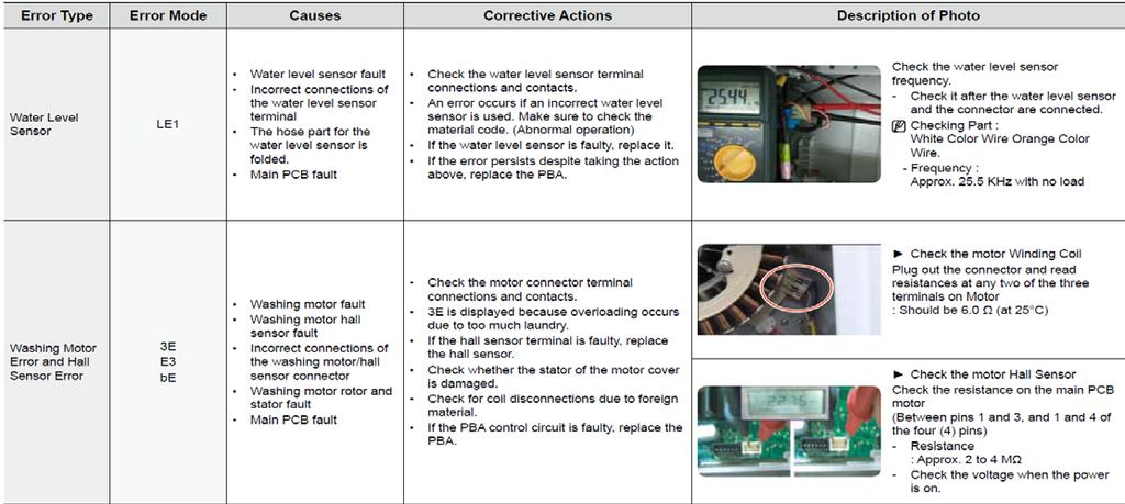
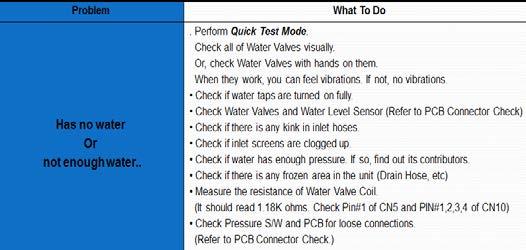
2 Check the water level sensor frequency. Frequency should be approx when empty. Approx 24.5 when full 2. Disconnect the connector and check resistance Pin 1 & 2 / 2 & 3 should be OPEN, if resistance is read between these points you have a short replace sensor switch. Pin 1 & 3 resistance is normal.
3

 If this is happening press start to run again, during the 3 rd")
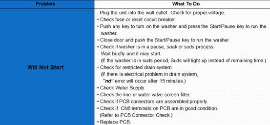
4 Note: Some errors do not display or get recorded to memory until running a cycle 3 times! ( Drain pump will run for 3mins but stops, screen remains on but washing does not continue ) If this is happening press start to run again, during the 3 rd attempt the error will display on the screen and get recorded to memory.

5 Additional Error codes Sd
6

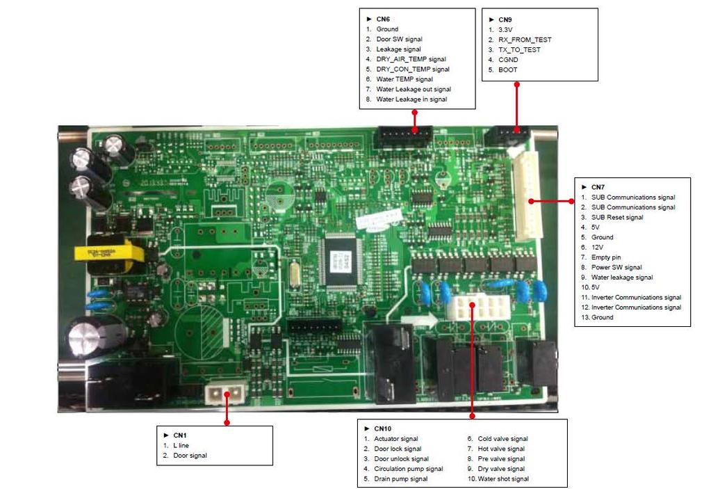
7 Main PCB Inverter PCB

8 Sub PCB Wiring Diagram


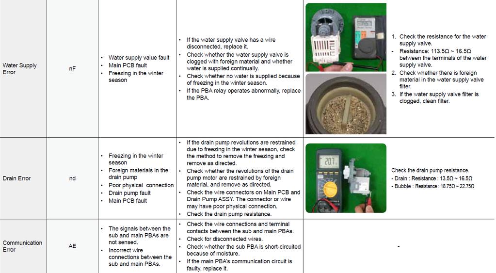
9 Checking the Inverter Board Test 1 Motor Connector Communication Connector Hall Sensor Connector Step 1: Put your black lead on the stator motor CN6 Pin1 and Red lead measure CN2 pin all measurements should be approx 4.6. Step 2: Put your black lead on the stator motor CN6 Pin 1 and Red lead measure CN1 pin all measurements should be approx 4.6. Step 3: Move the black lead to CN6 Pin2 and repeat steps above. Step 4: Move the black lead to CN6 Pin3 and repeat steps above. All measurements should be around 4.6 ohms.
10
11
Error code explanation Diagnostics...2 Error Code Chart...3 Tests Wiring diagram...6
 Washer Tech Data Sheet This information is intended for Qualified Technicians Only. CAUTION: DISCONNECT ELECTRICAL CURRENT BEFORE SERVICING Please Return This Sheet to its Envelope in the Product for Future
Model No. DFC-X Support DIRECT FIRED DIGITAL TEMPERATURE CONTROL INSTALLATION, OPERATION, AND MAINTENANCE MANUAL
 Model No. DFC-X Support 877-351-4702 DIRECT FIRED DIGITAL TEMPERATURE CONTROL INSTALLATION, OPERATION, AND MAINTENANCE MANUAL This manual covers the following products: DFC-X TS-01 DFTD RDU DAT-12 PWM-10V
SMART DRIVE ELECTRONIC WASHING MACHINE
 SMART DRIVE ELECTRONIC WASHING MACHINE MODEL GWL08US Service Supplement to be used in conjunction with GWL03US Service Manual Part Number PM912 Fisher & Paykel Appliances Inc 27 Hubble, Irvine, California,
DR: Camshaft Position (CMP) Sensor
 Sensor") 2007 PCED On Board Diagnostics SECTION 5: Pinpoint Tests Procedure revision date: 03/29/2006 DR: Camshaft Position () Sensor DR: Introduction DR1 CHECK FOR DIAGNOSTIC TROUBLE CODES (DTCS) Are DTCs P0340,
2007 PCED On Board Diagnostics SECTION 5: Pinpoint Tests Procedure revision date: 03/29/2006 DR: Camshaft Position () Sensor DR: Introduction DR1 CHECK FOR DIAGNOSTIC TROUBLE CODES (DTCS) Are DTCs P0340,
HP21 SERVICE SUPPLEMENT UNIT INFORMATION. TSC6 Two-Speed Control
 SERVICE UNIT INFORMATION SUPPLEMENT HP21 Corp. 9426 L10 Litho U.S.A. All HP21-4 and -5 units (single and three phase) are equipped with a TSC6 two-speed control. The TSC6 (A14) two-speed control contains
! WARNING To avoid risk of electrical shock, personal injury, or death, disconnect power to range before servicing, unless testing requires power.
 Electric Freestanding Range Technical Information AER5712BA* MER5751BA* MER5752BA* MERH752BA* MERM752BA* Due to possibility of personal injury or property damage, always contact an authorized technician
Motor. Document # Vari-Green Motor and Controls. Table of Contents. Features, Operation, Wiring and Troubleshooting
 Document #473681 Vari-Green Motor and Controls Installation, Operation and Maintenance Manual Please read and save these instructions for future reference. Read carefully before attempting to assemble,
TROUBLESHOOTING TP. Index
 TROUBLESHOOTING TP Index E1 POWER CUT DETECTED... 2 E2 LOCK ERROR... 3 E3 DRAINAGE FAILURE / WATER IN TUB... 6 E4 MAXIMUM WATER LEVEL REACHED... 6 E5 FAULT WATER INLET... 6 E6 HEATING FAULT... 6 E7 MAXIMUM
K10 Intrinsically Safe Electro-Pneumatic Positioner Operating Manual
 K0 Intrinsically Safe Electro-Pneumatic Positioner Operating Manual Pneumatic Connection Outlet Port Gauge Single Acting Actuator (Spring Return): For single acting actuators Outlet Port 2 is to be plugged.
LG Air Conditioning Universal & Multi Split Fault Codes Sheet. Universal and Multi Split Units
 Universal and Multi Split Units If there is a fault on any LG Universal or Multi unit, a two digit number will appear on the remote controllers led display. If the unit does not have a remote controller
! WARNING To avoid risk of electrical shock, personal injury, or death, disconnect power to range before servicing, unless testing requires power.
 Electric Freestanding Range Technical Information MER5875RA* Due to possibility of personal injury or property damage, always contact an authorized technician for servicing or repair of this unit. Refer
! WARNING To avoid risk of electrical shock, personal injury or death; disconnect power to oven before servicing, unless testing requires power.
 Technical Information Double Oven Dual Fuel Range JDR8895AAB/S/W Due to possibility of personal injury or property damage, always contact an authorized technician for servicing or repair of this unit.
Installation, Operation and Maintenance Manual
 Document 47681 Vari-Green Motor and Controls Installation, Operation and Maintenance Manual Please read and save these instructions for future reference. Read carefully before attempting to assemble, install,
Installation, Operation and Maintenance Manual
 Document 473681 Vari-Green Motor and Controls Installation, Operation and Maintenance Manual Please read and save these instructions for future reference. Read carefully before attempting to assemble,
Service Bulletin Power Sliding Door Operation and Troubleshooting (Replaces , Power Sliding Door Problems, dated April 20, 1999)
") Service Bulletin 01-051 Applies To: 1999 2001 Odyssey ALL May 8, 2001 Power Sliding Door Operation and Troubleshooting (Replaces 99-027, Power Sliding Door Problems, dated April 20, 1999) BACKGROUND The
Service Bulletin 01-051 Applies To: 1999 2001 Odyssey ALL May 8, 2001 Power Sliding Door Operation and Troubleshooting (Replaces 99-027, Power Sliding Door Problems, dated April 20, 1999) BACKGROUND The
! WARNING To avoid risk of electrical shock, personal injury or death; disconnect power to range before servicing, unless testing requires power.
 Double Oven Electric Range Technical Information MER6765BA* Due to possibility of personal injury or property damage, always contact an authorized technician for servicing or repair of this unit. Refer
SECTION 2 - PROCEDURES. Features. 2.6 MOTOR CONTROLLER. Modes of Operation JLG Lift 2-5
 2.6 MOTOR CONTROLLER. Modes of Operation. 1. Traction Motor Drive. a. Drive in either forward or reverse will start only if the following conditions are satisfied: 1. Function switches off. 2. No procedure
BRIVIS DUCTED INVERTER SERVICE MANUAL DRCi
 BRIVIS DUCTED INVERTER SERVICE MANUAL DRCi 1 TABLE OF CONTENTS TABLE OF CONTENTS... 2 IMPORTANT NOTE... 3 FAULT FINDING AND DIAGNOSTICS... 3 ABBREVIATIONS... 3 PCB S... 4 OUTDOOR MAIN PCB... 4 INDOOR PCB...
EBIKE DIAGNOSIS FLOWS
 EBIKE DIAGSIS FLOWS 1 SUMMARY Check Tool Instructions 2 Display and Controller check tool 3 Display Holder check tool 7 Motor check tool 8 Battery check tool 9 Torque Sensor check tool 12 Customized controller
SRC. An Outdoor Reset Control for Sub-Atmosphere Steam Systems OUTDOOR TEMPERATURE
 SRC STEAM RESET CONTROL An Outdoor Reset Control for Sub-Atmosphere Steam Systems Heat-Timer s theory of steam reset heating is as follows: Pulse the valve open to a limited valve position, very slowly
AUTO-BLiP. User Manual Porsche INTELLIGENT DOWNSHIFTS. Version 1.2
 AUTO-BLiP INTELLIGENT DOWNSHIFTS www.auto-blip.com User Manual 2005+ Porsche Version 1.2 Copyright 2012 Tractive Technology, LLC. All rights reserved. Page 1 WARNING Use of the AUTO-BLiP while driving
Installation, Operation and Maintenance Manual
 Document 47681 Vari-Green Motor and Controls Installation, Operation and Maintenance Manual Please read and save these instructions for future reference. Read carefully before attempting to assemble, install,
! WARNING To avoid risk of electrical shock, personal injury or death; disconnect power to range before servicing, unless testing requires power.
 Double Oven Electric Range Technical Information MER6875BA* Due to possibility of personal injury or property damage, always contact an authorized technician for servicing or repair of this unit. Refer
INTRODUCTION PRELIMINARY DIAGNOSIS
 NO: 21-11-98 SUBJECT: Transmission Simulator Diagnostic Tool DATE: Dec. 11, 1998 NOTE: THIS INFORMATION APPLIES TO VEHICLES EQUIPPED WITH A 45RFE TRANSMISSION. DISCUSSION: A new transmission simulator
RENA AF371Feeder Operating Manual. Feeder. Operating Manual. Manual Part #: M AF371 Operations Rev
 Manual Part #: M-3022 Feeder AF371 Operations Rev. 3-16-04 1 RENA AF371 Feeder YOUR RENA AF371 IS DISTRIBUTED BY RENA SYSTEMS INC. SERVICE AND SUPPORT FOR THIS PRODUCT IS PROVIDED BY YOUR RENA DEALER.
Procedure revision date: 09/16/2004 DR1 CONTINUOUS MEMORY DTCS P0340 AND P0345: CHECK IF THE ENGINE WILL START
 11/4/2017 PPT DR: Camshaft Position () Sensor - On Board Diagnostics (Powertrain Diagnostics) 2004 Ford F-150 MotoLogic 2004 F-150 2004 PCED On Board Diagnostics SECTION 5: Pinpoint Tests Report a problem
Pivotell Advance Automatic Pill Dispenser Instructions
 Pivotell Advance Automatic Pill Dispenser Instructions Note: When opening for the first time, the lid is unlocked. The key and battery case securing screw can be found inside the dispenser. V11 102016
Operating Instructions Type MPT 53
 Operating Instructions www.turnstiles.us Type MPT 53 Contents 1. Delivery... 2 2. Safety...3-4 3 Description and operation... 5 4. Technical Data 6 5. oundation...6-9 6. Assembly and installation...10-13
materials and workmanship for 2 years. Should the centrifuge require warranty or Phone: or Fax:
 WARRANTY The Drucker Company warranties that this centrifuge is free from defects in materials and workmanship for 2 years. Should the centrifuge require warranty or out-of-warranty service please contact:
INTRODUCTION INSTALLATION
 INTRODUCTION INSTALLATION, OPERATION & MAINTENANCE INSTRUCTIONS This instruction manual includes installation, operation and maintenance information for the figure G73 gear operator. The figure G73 is
DFC-1 STANDARD TEMPERATURE CONTROL. DFC-2 TEMPERATURE CONTROL w/ INTEGRAL 40 F-90 F SELECTOR DFTD TEMPERATURE SELECTION DIAL DFTS TEMPERATURE SENSOR
 24 Volt AC input Built in 15 second low fire start timer 0-24 Volt DC modulating output Remote temperature selection Calibration trim pot Rated for -40 F (-40 C) DFC-1 STANDARD TEMPERATURE CONTROL DFC-2
SERVICE MANUAL WASHING. Washing machines. guide to diagnostics of electronic controls
 RVIC MANUAL WAHING LCTROLUX ITAL.p.A. pares Operation urope Corso Lino Zanussi, 30 Publication number I - 33080 PORCIA/PN (ITAL) 599 73 77-37 Washing machines guide to diagnostics of electronic controls
Installation, Operation and Maintenance Manual
 Document 473681 Vari-Green Motor and Controls Installation, Operation and Maintenance Manual Please read and save these instructions for future reference. Read carefully before attempting to assemble,
Analog Durometer Model AD-100
 CHECK LINE BY ELECTROMATIC Analog Durometer Model AD-100 Operating Instructions Table of Contents 1.0 Introduction... 2 1.1 Unpacking 1.2 Complete Kit 2.0 Testing Procedure... 3 3.0 Memory Pointer... 4
Statim G4 Error Codes
 Statim G4 Error Codes All leaks should be corrected before proceeding with troubleshooting Cycle Fault #1 The cassette temperature failed to reach 95 C within a time-out period. 1. An extremely large steam
TC62D Installation Instructions
 TC62D Installation Instructions January 2007 This TC62D has a return water low temperature limit option. Using the low limit precludes using a room sensor because both sensors plug into the same port.
Freedom egen System End-of- Line Functional Checklist
 U Freedom egen System End-of- Line Functional Checklist 976-0361-01-01 Rev A April 2018 DANGER RISK OF FIRE, ELECTRIC SHOCK, EXPLOSION, AND ARC FLASH This checklist is in addition to, and incorporates
AUTO-BLiP. User Manual Lotus INTELLIGENT DOWNSHIFTS. Version 1.0
 AUTO-BLiP INTELLIGENT DOWNSHIFTS www.auto-blip.com User Manual Lotus Version 1.0 Copyright 2012 Tractive Technology, LLC. All rights reserved. Page 1 WARNING Use of the AUTO-BLiP while driving could lead
Electrical Accessories
 Electrical Accessories Power accessories are designed many different ways Always use a wiring diagram to figure out how your system is designed Wiring diagram will allow you to decide how and where to
WF-5110R True Sine Wave Inverter
 Operator s Manual WF-5110R True Sine Wave Inverter WF-9900 Series WF-5110R ( The Inverter model number is located on the label on top of the enclosure) Distributed in the U.S.A. and Canada by ARTERRA DISTRIBUTION
Model 8000XL OPERATOR MANUAL
 Model 8000XL OPERATOR MANUAL DORAN SCALES, INC. 1315 PARAMOUNT PKWY. BATAVIA, IL 60510 1-800-262-6844 FAX: (630) 879-0073 http://www.doranscales.com MANUAL REVISION: 1.0 MAN0191 10/3/2005 INTRODUCTION
1.2 Instrument Cluster (CLUS) Contents
 Contents") 1.2 Instrument Cluster (CLUS) Contents 1.2 Model 129 Page Diagnosis Function Test................................... 11/1 Complaint Related Diagnostic Chart................... 12/1 Electrical Test Program
1.2 Instrument Cluster (CLUS) Contents 1.2 Model 129 Page Diagnosis Function Test................................... 11/1 Complaint Related Diagnostic Chart................... 12/1 Electrical Test Program
CAUTION All safety information must be followed as provided in Service Manual
 Double Oven Gas Range Technical Information MGR6875AD* Due to possibility of personal injury or property damage, always contact an authorized technician for servicing or repair of this unit. Refer to Service
DA: Intake Air Temperature (IAT) Sensor
 Sensor") 2007 PCED On Board Diagnostics SECTION 5: Pinpoint Tests Procedure revision date: 03/29/2006 DA: Intake Air Temperature () Sensor DA: Introduction DA1 CHECK FOR DIAGNOSTIC TROUBLE CODES (DTCS) Are DTCs
2007 PCED On Board Diagnostics SECTION 5: Pinpoint Tests Procedure revision date: 03/29/2006 DA: Intake Air Temperature () Sensor DA: Introduction DA1 CHECK FOR DIAGNOSTIC TROUBLE CODES (DTCS) Are DTCs
AUTO-BLiP. User Manual Ford Mustang INTELLIGENT DOWNSHIFTS. Version 1.2
 AUTO-BLiP INTELLIGENT DOWNSHIFTS www.auto-blip.com User Manual 2015-2016 Ford Mustang Version 1.2 Copyright 2012 Tractive Technology, LLC. All rights reserved. Page 1 WARNING Use of the AUTO-BLiP while
FREEWAY RANGE OWNERS MANUAL. All PowaKaddy electric trolleys have been awarded the Quiet Mark by the Noise Abatement Society
 FREEWAY RANGE OWNERS MANUAL All PowaKaddy electric trolleys have been awarded the Quiet Mark by the Noise Abatement Society Thank you for purchasing the new PowaKaddy. We hope you enjoy your new trolley
CI 3000 Coil Inserter
 CI 3000 Coil Inserter Setup & Operator Manual Issue 1 April 02 Performance Design Inc. The CI 3000 plastic spiral inserter will bind books up to 1-1/8 (28.6mm) thick using coil diameters from 3/16 (5mm)
1980 Rotating Cam Limit Switches. Ordering Guide & Technical Information
 1980 Rotating Cam Limit Switches Ordering Guide & Technical Information Features Precision Cam adjustment at any angular position of the Camshaft Speeds from 0 to 500 RPM in either direction No special
FA: AMBIENT AIR TEMPERATURE (AAT) SENSOR: PINPOINT TEST
 SENSOR: PINPOINT TEST") 2014 Ford Taurus FWD V6-35L Vehicle > Powertrain Management > Computers and Control Systems > Testing and Inspection > Pinpoint Tests FA: AMBIENT AIR TEMPERATURE (AAT) SENSOR: PINPOINT TEST FA: Ambient
2014 Ford Taurus FWD V6-35L Vehicle > Powertrain Management > Computers and Control Systems > Testing and Inspection > Pinpoint Tests FA: AMBIENT AIR TEMPERATURE (AAT) SENSOR: PINPOINT TEST FA: Ambient
Application Engineering Europe
 Date of last update: Feb-12 Ref: D7.8.4/0112-0212/E Application Engineering Europe CORESENSE DIAGNOSTICS FOR STREAM REFRIGERATION COMPRESSORS 1/17 1 Introduction CoreSense is an ingredient brand name for
Table of Contents. Timer Identification Timer ID BLU-U Features: 1K 6K BLU-U Features 1K 6K
 DUSA Pharmaceuticals, Inc. Table of Contents Go to Chart # Timer Identification Timer ID BLU-U Features: 1K 6K BLU-U Features 1K 6K BLU-U Features: 10K BLU-U Features 10K BLU-U Symptom Fans Running, Timer
APPLICATION NOTES VALVE CHECKER M
 APPLICATION NOTES VALVE CHECKER M040-120-001 1 of 16 CONTENTS Chapter Title Page 1. Description 3 2. Specification 7 3. Connecting to valve and plant 8 4. Plant mode operation (in line) 9 5. Checker mode
USER MANUAL BRUSHLESS SPEED CONTROLLER S5-RTR ESC S5A-RTR ESC RC CARS & TRUCKS
 USER MANUAL BRUSHLESS SPEED CONTROLLER S5-RTR ESC S5A-RTR ESC RC CARS & TRUCKS Declaration Thanks for purchasing our Electronic Speed Controller (ESC). High power system for RC model can be very dangerous,
Centrifuge Operator / Service Manual
 3000 Centrifuge Centrifuge Operator / Service Manual cat.# 26230 & 26231 The Q-sep 3000 centrifuge complies with all requirements of UL standard 3101 20, Can/CSA C22.2 No. 1010.1, and Can/CSA C22.2 No.
M40/50RF System - Installers Guide
 M40/50RF System - Installers Guide Contents Glossary... 3 M40/50RF Motor... 3 SUITE Remote... 3 Battery Installation... 3 Introduction... 4 1) Install the Shade... 4 2) Create the Hub Motor... 4 3) Join
User Guide AutoTrans Conveyor. Operation & Service
 User Guide AutoTrans Conveyor Operation & Service Table of Contents 1 Introduction... 1 2 Specifications, Features & Accessories... 2 2.1 Specifications... 2 2.2 Features... 2 2.3 Accessories... 2 3 Identification
! WARNING To avoid risk of electrical shock, personal injury or death; disconnect power to oven before servicing, unless testing requires power.
 Technical Information Double Oven Electric Range MER6555AAB/Q/W MER6751AAB/Q/S/W MER6755AAB/Q/S/W MER6775AAB/F/N/Q/S/W Due to possibility of personal injury or property damage, always contact an authorized
Rev. 12/14/2001. PC-5500 PC-5750 Operation Manual
 Rev. 12/14/2001 PC-5500 PC-5750 Operation Manual Operation Configuration Troubleshooting PC-5500 PC-5750 Custom Control Systems Inc. 2007 Beech Grove Place Utica, NY 13501 (315) 732-1990 www.customcontrolsystems.com
RR Concepts. The StationMaster can control DC trains or DCC equipped trains set to linear mode.
 Jan, 0 S RR Concepts M tation aster - 5 Train Controller - V software This manual contains detailed hookup and programming instructions for the StationMaster train controller available in a AMP or 0AMP
AUTO-BLiP. User Manual Chevrolet Corvette. Version 1.2
 AUTO-BLiP INTELLIGENT DOWNSHIFTS www.auto-blip.com User Manual 1997-2004 Chevrolet Corvette Version 1.2 Copyright 2012 Tractive Technology, LLC. All rights reserved. Page 1 WARNING Use of the AUTO-BLiP
Spray Height Controller
 Spray Height Controller UC5 SERVICE MANUAL 2012 Printed in Canada Copyright 2012 by NORAC Systems International Inc. Reorder P/N: UC5 SERVICE MANUAL 2012 Rev B NOTICE: NORAC Systems International Inc.
Service Bulletin
 Service Bulletin 17-015 September 6, 2017 07188 Version 2 8-Speed Transmission (DCT) Has a Bump or Hard Shift When Coming to a Stop Supersedes 17-015, dated April 26, 2017, to revise the information highlighted
STR3. Step Motor Drive. User Manual
 STR3 Step Motor Drive User Manual Contents 1 Introduction... 3 1.1 Overview... 3 1.2 Features... 3 1.3 Block Diagram... 4 1.4 Safety Instructions... 5 2 Getting Started... 6 2.1 Mounting Hardware... 6
MODEL MVX-2011 TANK MOUNT SPEEDOMETER/TACHOMETER
 MODEL MVX-2011 TANK MOUNT SPEEDOMETER/TACHOMETER Wiring Diagram The MVX-2011 gauges will work on 2011-up Softail models with 5 gauges or 2012-up Dyna models with 5 gauges. It is a direct plug in on these
PARTS & SERVICE MANUAL
 PARTS & SERVICE MANUAL Impinger Low Profile Advantage Digital Series (Electric) International Models MODELS: Please note that the model numbering system changed March 2007. The chart below shows the old
MODEL 853VES Model 853VES Operator s Manual
 MODEL 853VES Model 853VES Operator s Manual Laboratory Centrifuge P/N 7711012 Rev. C Table of Contents Model Description... 3 Supplied Equipment... 3 Warranty Information... 3 Specifications... 4 Control
Phenix Technologies Inc. 75 Speicher Drive Accident, Maryland 21520
 USER S MANUAL PORTABLE HIGH CURRENT TEST SET MODEL NUMBER HC2 Version 4.0 Phenix Technologies Inc. 75 Speicher Drive Accident, Maryland 21520 Copyright Phenix Technologies, Inc. Rev 11/20/2014 nab TABLE
OP-500 On-Premise Series Instruction Manual
 OP-500 On-Premise Series Instruction Manual Page 1 of 16 7$%/(2)&217(176 Quick Start Programming...3 Introduction...4 System Overview...4 Pre-Installation...4 Installation...4 Split Commons...5 Getting
Advanced Test Equipment Rentals ATEC (2832)
") Established 1981 Advanced Test Equipment Rentals www.atecorp.com 800-404-ATEC (2832) INSTRUCTIONS FOR MAGNUM DS TRIP UNIT TESTING USING TEST KIT SYLES 140D481G02R, 140D481G02RR, 140D481G03 AND 140D481G04
Established 1981 Advanced Test Equipment Rentals www.atecorp.com 800-404-ATEC (2832) INSTRUCTIONS FOR MAGNUM DS TRIP UNIT TESTING USING TEST KIT SYLES 140D481G02R, 140D481G02RR, 140D481G03 AND 140D481G04
! WARNING To avoid risk of electrical shock, personal injury or death; disconnect power to oven before servicing, unless testing requires it.
 Electric Wall Oven Technical Information AEW3630DD*, AEW4630DD*, JJW8230DD* MEW5627DD*, MEW5630DD*, MEW6627DD*, MEW6630DD*, Refer to Service Manual 6022506 for detailed installation, operating, testing,
Setup and Programming Manual
 Microprocessor and Handy Terminal Setup and Programming Manual Versions U04 to U19 for Sliding Door Systems P/N 159000 Rev 7-2-07 The manufacturer, NABCO Entrances, Inc. suggests that this manual be given
INSTRUCTION MANUAL. A battery protector for vehicles with equipment that Is operated with the engine not running. MODEL# INPUT: 12 Volts D.C.
 INSTRUCTION MANUAL FILE: IM_091-141_Rev_B DATE: 10-02-03 LOAD MANAGER P A battery protector for vehicles with equipment that Is operated with the engine not running MODEL# 091-141 INPUT: 12 Volts D.C.
CONTROL BOX. Wiring the control box into the vehicle. +12V
 CONTROL BOX Once the display panel is in place, mount the control box within the connecting cable's distance (approximately 3 feet) and secure to the underside of the dashboard. This case does not have
BKF Control Panel Instruction Manual for the Owners
 1 Contents 2 Exploitation and maintenance... 2 2.1 Control Panel (CP)... 2 2.1.1 Panel Operation... 2 2.1.2 Start Page... 2 2.1.3 Stands... 3 2.1.4 Osmosis... 3 2.1.5 Diagnostics... 4 2.1.6 Engine speed...
P8U-FM FEATURES AND OPERATIONS REMOTE STARTER ANTI-START SYSTEM SECURITY SYSTEM
 P8U-FM FEATURES AND OPERATIONS REMOTE STARTER ANTI-START SYSTEM SECURITY SYSTEM TRANSMITTER OPERATIONS Button Function Arm & Lock the Doors Disarm & Unlock the Doors Start / Stop the Engine Description
Installation and Service Manual M² Sync Room Slideout System without Room Lock Connectors on Control Box
 Installation & Service Manual M² Sync Room Slideout System w/o Room Locks: for Slideout Control Box# 1510000143 and 1510000198 Figure 1 01/13 Power Gear #3010002088 Rev. 0C Installation and Service Manual
DC TO AC POWER INVERTER PWRIC150012W INSTRUCTION MANUAL
 DC TO AC POWER INVERTER PWRIC150012W INSTRUCTION MANUAL SAVE THIS MANUAL You will need the manual for the safety warnings and precautions, assembly instructions, operating and maintenance procedures, parts
Section 55 Chapter 6
 Section 55 Chapter 6 REMOTE HYDRAULICS CONTROLLER Calibration and Fault Codes 6-12880NH TABLE OF CONTENTS REMOTE HYDRAULICS CONTROLLER CALIBRATION... 55-5 Requirements For Calibration... 55-5 Aux Set Main
Automated Control Electronics (ACE ) System Operation and Diagnostics
 System Operation and Diagnostics") Commercial Products Automated Control Electronics (ACE ) System Operation and Diagnostics PART NO. 98962SL This page is intentionally blank. Table of Contents Introduction... 1 Controller Operation and
Commercial Products Automated Control Electronics (ACE ) System Operation and Diagnostics PART NO. 98962SL This page is intentionally blank. Table of Contents Introduction... 1 Controller Operation and
TM-9100 Series Room Command Module
 FANs 216, 1628.3 Product/Technical Bulletin TM-9100 Issue Date 0400 TM-9100 Series Room Command Module The TM-9100 Series Room Command Modules are designed for use with the TC-9100 series of DDC (Direct
EWC-350/850. Commercial model - indoor/outdoor installation Operation Manual. H2oEliteLabs.com
 EWC-350/850 Commercial model - indoor/outdoor installation Operation Manual H2oEliteLabs.com Table of Contents Page 2: Table of contents Page 3: What s included, Types of pipes that can be used and EWC-350/850
Installation Manual. Remote Temperature Sensor KS9-BS1-A. Instructions for :- Remote Temperature Sensor
 Issue 4 Installation Manual Instructions for :- KS9-BS1-A For safe and correct use please read this installation manual and the relevant Mitsubishi Electric installation manual Manufactured for MITSUBISHI
Fault Codes. J control
 J control Timer Temp Fault Codes 12 11 10 9 8 7 6 5 4 3 2 1 30 29 28 27 26 25 24 23 22 21 20 Enter unit inspection mode by pushing the UP and DOWN buttons simultaneously for two seconds. Ensure that the
Installation & Programming Manual. Quick Reference
 Installation & Programming Manual Getting Started Prepare door, per additional instructions (included) before installing unit. IMPORTANT: Read instructions completely before beginning installation. Refer
Coil Inserter Module
 Coil Inserter Module 1) Installation Instructions: Diagram 4 Procedure to attach the coil inserter onto the OD 4012 punch Unplug the main power cord from the OD 4012. Remove the two safety screws (3/32
AFT mid drive kit Trouble shooting guide For 24v to 48V Kelly Controller KBS 48101L-L 100 A peak
 Date: 2016-13-1 AFT mid drive kit trouble shooting guide Rev 1.7 Page 1 of 17 AFT mid drive kit Trouble shooting guide For 24v to 48V Kelly Controller KBS 48101L-L 100 Table of Contents 1. Safety... 2
Operating instructions Flow monitor SI / / 2014
 Operating instructions monitor SI5002 80000385 / 00 07 / 2014 Contents 1 Preliminary note...3 1.1 Explanation of symbols...3 2 Safety instructions...3 3 Functions and features...4 3.1 Applications...4
Micro Autonomations LLC
 Description Micro Autonomations LLC www.ma-embedded.com Mercedes Fan Controller V2.1 This module controls C-Class fans from Mercedes. It has three different methods to control the fan. It will vary the
1 This instrument must only be used by a competent and trained person and operated in strict accordance with the instructions.
 1 This instrument must only be used by a competent and trained person and operated in strict accordance with the instructions. KYORITSU will not accept liability for any damage or injury caused by misuse
BLDC SPEED CONTROL INSTRUCTION MANUAL Low voltage Brushless DC control
 BLDC SPEED CONTROL INSTRUCTION MANUAL Low voltage Brushless DC control Phone 712.722.4135 groschopp.com 420 15th St NE, Sioux Center, IA 51250 Toll-Free 800.829.4135 Email sales@groschopp.com FAX 712.722.1445
On-Premise Pro Instruction Manual
 On-Premise Pro Instruction Manual 0901133 Rev: A (11/13) Page 1 of 20 TABLE OF CONTENTS Introduction... 4 Features... 4 Pre-installation... 5 Installation... 5 Operating Modes... 6 Programming... 7 Load
REMOTE CONTROLLED DOG TRAINING COLLARS
 REMOTE CONTROLLED DOG TRAINING COLLARS OWNER S MANUAL Dogtra Company 1250 E. 223rd Street, Suite 119 Carson, CA 90745 Tel :(310) 522-1800 Fax :(310) 522-1805 Web Site : www.dogtra.com Toll Free: 1-888-
PRODUCT MANUAL Onyx 2 Zone In-Wall Wireless LED Dimmer and Receiver
 Product Description Main Functions: Control Up to 2 Zones Independently Wireless Control for Quick and Easy Installation Touch Sensitive Dark Glass Surface 50 Foot Wireless Range Soft Touch On/Off Memory
Cooking Products Fault Code Reference Guide
 CLEAN OVE N 1 STOP 2 ON TIMER P R B CONV BROIL PRE- DELAY TIMED BAKE CLEAN LOC K ON DELAY BAKE CLN STOP TIMER BROIL CONV DELAY BAKE CLEAN LOCKED Cooking Products Reference Guide 2004 Maytag Services September,
INSTALLATION GUIDE Table of Contents
 CT-3100 Automatic transmission remote engine starter systems. What s included..2 INSTALLATION GUIDE Table of Contents Door lock toggle mode..... 4 Notice...2 Installation points to remember. 2 Features..2
SRS AIRBAG CONTROL SYSTEM
 RESTRAINTS SECTION SRC A SRS AIRBAG CONTROL SYSTEM B C D CONTENTS E BASIC INSPECTION... 3 DIAGNOSIS AND REPAIR WORK FLOW... 3 Work Flow...3 INTERMITTENT INCIDENT... 5 Inspection Procedure...5 Trouble Diagnosis
ITA / ITB - AS / AP / AP SERIES Electronic Table Top Weighing Balance
 TM ITA / ITB - AS / AP / AP SERIES Electronic Table Top Weighing Balance Scale Users Guide ISHTAA SCALES INC., INDIA www.ishtaascales.com 14 Content 1. Technical Data... 1 2. Installation... 2 3. Controls
DUAL LINEAR MOTOR / ACTUATOR CONTROLLER W/ CURRENT SENSING AUTO REVERSE
 PAC-3200 DUAL LINEAR MOTOR / ACTUATOR CONTROLLER W/ CURRENT SENSING AUTO REVERSE PAC-3200 PRESET BUTTONS MOTOR 2 DUAL LINEAR MOTOR CONTROLLER WITH SAFETY REVERSE MOTOR 2 MOTOR 1 MAIN #1 ACC DISABLE #2
Table of Contents. E70 Transmissions
 Table of Contents Subject Page New Transmissions for E70....................................5 Changes.......................................................5 Technical Data...............................................6
Special Features. Specifications Motor Types: Sensored Motor Limit: 2.5T (on 2S) Input Voltage: 2-3S LiPo Direction: Forward, Brake, Reverse
 Input Voltage: 2-3S LiPo Direction: Forward, Brake, Reverse") MS-1 ELECTRONIC SPEED CONTROL Thank you for choosing TrakPower as your source for brushless electronics. The MS-1 ESC was specifically developed for 1/10th competition. The MS-1 ESC features an aluminum
MS-1 ELECTRONIC SPEED CONTROL Thank you for choosing TrakPower as your source for brushless electronics. The MS-1 ESC was specifically developed for 1/10th competition. The MS-1 ESC features an aluminum