Today, we offer high-performance machines with innovative solutions that meet the needs of woodworkers and their ever-evolving craft.
|
|
|
- Elvin Potter
- 5 years ago
- Views:
Transcription

1
2 Dear Woodworker: Thank you for your purchase and welcome to the Laguna Tools group of discriminating woodworkers. I understand that you have a choice of where to purchase your machines and appreciate the confidence you have in our products. Every machine sold by Laguna Tools has been carefully designed and well thought through from a woodworker s perspective. I cut on our bandsaws, lathes, table saws and combination machines. Through my hands-on experience, I work hard to make our machines better. I strive to give you machines that inspire you to create works of art. Machines that are a joy to run and work on. Machines that encourage your performance. Today, we offer high-performance machines with innovative solutions that meet the needs of woodworkers and their ever-evolving craft. I started Laguna Tools as a woodworker; I still am. Thank you again for becoming a Laguna Tools customer. Torben Helshoj President and Founder Laguna Tools Imagination, Innovation and Invention at work.
3 Table of contents Page number Safety Rules 4 Warranty 5 Noise emission 6 Specification sheet 6 Receiving your wide belt sander 7 Introduction to your wide belt sander 8 What you will receive. 12 Parts of the wide belt sander 8 Where to locate your wide belt sander 12 Unpacking your wide belt sander 13 Assembly and setup 13 Adjusting the wide belt sander 18 Running the sander 24 Maintenance and troubleshooting 27 Electrical drawing 40 Exploded view drawings 41 3
4 Safety Rules. As with all machinery, there are certain hazards involved with the operation and use. Using it with caution will considerably lessen the possibility of personal injury. However, if normal safety precautions are overlooked or ignored, personal injury to the operator may result. If you have any questions relative to the installation and operation, do not use the equipment until you have contacted your supplying distributor. Read the following carefully before operating the machine. 1. Keep the working area clean and be sure adequate lighting is available. 2. Do not wear loose clothing, gloves, bracelets, necklaces or ornaments. Wear face, eye, respiratory and body protection devices as indicated for the operation or the environment. 3. Be sure that the power is disconnected from the machine before tools are serviced or an attachment is to be fitted or removed. 4. Never leave the machine with the power on. 5. Do not use dull, gummy or cracked cutting tools. 6. Be sure that the keys and adjusting wrenches have been removed and all the nuts and bolts are secured. 4
5 LIMITED WARRANTY New woodworking machines sold by Laguna Tools carry a one-year warranty effective from the date of shipping. Laguna Tools guarantees all new machines sold to be free of manufacturer s defective workmanship, parts and materials. We will repair or replace, without charge, any parts determined by Laguna Tools, Inc., to be a manufacturer s defect. We require that the defective item/part be returned to Laguna Tools with the complaint. In the event the item/part is determined to be damaged due to lack of maintenance, cleaning or misuse/abuse, the customer will be responsible for the cost to replace the item/part, plus all related shipping charges. This limited warranty does not apply to natural disasters, acts of terrorism, normal wear and tear, product failure due to lack of maintenance or cleaning, damage caused by accident, neglect, lack of or inadequate dust collection, misuse/abuse or damage caused where repair or alterations have been made or attempted by others. Laguna Tools, Inc., is not responsible for additional tools or modifications sold or performed (other than from/by Laguna Tools, Inc.) on any Laguna Tools, Inc., woodworking machine. Warranty maybe voided upon the addition of such described tools and/or modifications, determined on a case-by-case basis. Normal user alignment, adjustment, tuning and machine settings are not covered by this warranty. It is the responsibility of the user to understand basic woodworking machinery settings and procedures and to properly maintain the equipment in accordance with the standards provided by the manufacturer. Parts, under warranty, are shipped at Laguna Tools, Inc. s cost either by common carrier, FEDEX ground service or a similar method. Technical support to install replacement parts is primarily provided by phone, fax, e- mail or Laguna Tools Customer Support Website. The labor required to install replacement parts is the responsibility of the user. Laguna Tools is not responsible for damage or loss caused by a freight company or other circumstances not in our control. All claims for loss or damaged goods must be notified to Laguna Tools within twenty-four hours of delivery. Please contact our Customer Service Department for more information. Only new machines sold to the original owner are covered by this warranty. For warranty repair information, call Copyright 2010 Laguna Tools, Inc ** Warning no portion of these materials may be reproduced without written approval from Laguna Tools, Inc. 5
6 Noise emission. Notes concerning noise emission. Given that there exists a relationship between noise level and exposure times, it is not precise enough to determine the need for supplementary precautions. The factors affecting the true level of exposure to operators are clearly the amount of time exposed, the characteristics of the working environment, such as other sources of dust and noise for example, adjacent machines in other words, the level of ambient noise. It is possible that exposure level limits will vary from country to country. Specification sheet for wide belt sander. SPECIFICATION Main motor 20HP Variable feed speed 1HP Table lifting motor 0.25HP Voltage 220V / three phase Max sanding height 5" (127 mm) Min sanding height 1/4" (6.4 mm) Max sanding width 36 1/2" (927 mm) Sanding belt size 37" x 75" (940 mm x 1905 mm) Diameter of sanding drum 4" (100 mm) Length of sanding drum 38" (965 mm) Sanding drum RPM 1725 RPM Conveyor speed FPM Dust port size 4" (100 mm) Number of dust ports 3 Foot print 19" x 51" (483 mm x 1300 mm) Width x Depth 25 1/2" x 52" (650 mm X 1320 mm) Height with dust collection ports 77 1/2" (1968 mm) Height without dust collection ports 71 1/2" (1816 mm) Conveyor height at lowest setting 32" (813 mm) Cabinet Steel Operating air pressure 6 Bar Sanding belt oscillation Adjustable Sanding belt motor break Yes. Air operated disc break 6

 as soon as practical.")

7 Receiving your wide belt sander. Note. It is probable that your machine will be delivered by a third party. Before you unpack your new machine, you will need to first inspect the packing, invoice and shipping documents supplied by the driver. Ensure that there is no visible damage to the packing or the machine. You need to do this prior to the driver leaving. All damage must be noted on the delivery documents and signed by you and the delivery driver. You must then contact the seller (Laguna Tools) as soon as practical. If damage is found after delivery, contact the seller as soon as is practical. Note. It is probable that you will find sawdust within your machine. This is because the machine has been tested prior to shipment from the factory and or Laguna Tools. Laguna Tools endeavors to test machines prior to shipping to customers, as movement can take place during transportation. It must be noted that additional machine movement can take place between Laguna Tools and the end user and that some adjustments may have to be undertaken by the customer. These adjustments are covered in the various sections of this manual. Wide belt sander with box removed 7


8 Introduction to your wide belt sander. This machine is designed to give you years of safe service. Read this owner s manual in its entirety before assembly or use. Parts of the wide belt sander. The wide belt sander consists of a number of major parts, which are discussed in this manual. Take the time to read this section and become familiar with the machine. Identification. There is a plate on the side of the machine listing all the manufacturing data, including the model Control panel. The control panel controls all the electrical functions of the machine. This includes the speed of the drive belt, vertical adjustment of the bed and on/off functions 2. Bed vertical setting device. This device is used to set the height of the bed in relation to the sanding rollers. 8
9 3. Manual bed vertical adjusting handle. This handle is used to manually adjust the bed vertically. 4. Bed. The bed of the sander has a rubber drive belt that transports the job through the machine. The speed of the belt is adjustable. 5. Safety plate. The safety plate is used to remove power from the motors. This is very convenient should a job get jammed, as it can be operated by hand, leg or hip. 6. Machine body. The machine body is manufactured from heavy-gauge steel. 7. Dust extraction. There are three dust extraction pipes located on the top of the machine and are 4 inches (100mm) in diameter. Dust extraction is critical when sanding. The sander produces a lot of sawdust that must be removed for health reasons and also because the belt will clog and poor surface finish will result. It is not possible to be exact when recommending what size of dust collector should be used; this will depend on the type of work that the machine is used for. It is recommended that a dust collector with a minimum of 3500 cubic feet/minute is attached to the sander. 8. Belt drive. The belt speed is variable between 6-30FPM. The belt speed is adjusted by the control knob, which must only be adjusted while the belt is running. To decrease the speed, turn the adjuster clockwise. To increase the speed, turn the adjuster counter-clockwise. 9. Air supply. A clean dry air supply with a minimum pressure of 6 bar must be connected to the sander. If the pressure drops below 5 bar, the machine will stop functioning. 10 Electrical control box. The electrical control box houses all the electrical control components and must never be opened while power is supplied to the machine. 9


10 Sanding drum motor. 12. Bed vertical adjusting motor. The bed vertical adjusting motor moves a chain that rotates four cogs. The cogs turn threaded shafts that lift or lower the bed. 13. Sanding belt limiter. There are two ceramic limiters, one on either side of the machine. If the belt hits either of the limiters, a micro switch is activated and the machine will stop. If the sanding belt hits any of the limiters, the sanding belt will have to be adjusted prior to restarting the sander. 14. Sanding belt sensor. This sensor controls the action of the sanding belt oscillation. As the belt moves in and out of the sensor, a piston moves a cam that is attached to the top sanding roller. This action changes the angle of the top roller and forces the belt to move along the roller. 15. Sanding belt control knobs. These knobs control the actions of the sanding belt sensor and also the amount of oscillation of the sanding belt. 10


11 Spacer. The spacer is used to clamp the sanding head to the body of the machine. The spacer is removed when changing sanding belts. 17. Platen adjuster. The platen can be adjusted lower than the sanding rollers. The amount below the rollers will vary depending on the type of sanding being conducted. If conducting rough sanding, the platen is adjusted above the sanding rollers so that it is not in contact with the sanding belt. 18. Sanding belt tensioning knob. The belt tensioning knob controls the amount of pressure that the piston exerts on the sanding belt. 19. Sanding belt adjustor. The sanding belt adjustor is used to adjust the belt centrally on the top roller. 20. Sanding belt oscillation piston. The sanding belt oscillation piston moves a cam that is attached to the top sanding roller. This action changes the angle of the top roller and oscillates the belt along the rollers. 21. Sanding belt tension piston. The piston keeps a constant pressure on the sanding belt and is retracted to allow the belts to be changed. 11


12 What you will receive with the wide belt sander. Door keys Grease gun flexible extender Spare platen backer Tools Platen extractor Spare ceramic belt limiters Spare platen Graphite pads Sanding belts Where to locate your wide belt sander. Before you remove your machine from the packaging, select the area where you will use your machine. There are no hard-and -fast rules for its location, but below are a few guidelines: 1. There should be an area at the front and back of the machine suitable for comfortable working and the length of the work pieces. 2. Adequate lighting. The better the lighting, the more accurately and safely you will be able to work. 3. Solid floor. You should select a solid, flat floor, preferably concrete or something similar. 4. Locate it close to a power source and dust collection. 5. Allow an area for the storage of blanks, finished products and tools. 12
13 Unpacking your wide belt sander. To unpack your sander, you will need tin snips, knife, screwdriver and a wrench. 1. Using the tin snips, cut the banding that is securing the packing box (if fitted). WARNING: EXTREME CAUTION MUST BE USED BECAUSE THE BANDING WILL SPRING AND COULD CAUSE INJURY. 2. Dismantle the box. 3. Remove any bolts that secure the machine to the base (if fitted). 4. Remove the machine from the base with a fork lift truck. The fork lift truck must have sufficient capacity to achieve the job safely. 5. Remove the base and lower the machine to the floor. Note. If you have any doubt about the described procedure, seek professional assistance. Do not attempt any procedure that you feel is unsafe or that you do not have the physical capability of achieving. Assembly and setup. Very little assembly and setup is required, as the machine comes fully assembled. You will have to fit the sanding belt and connect the air and electricity. Cleaning the machine. Remove the rust protection grease with WD 40 or a similar solvent. It is important that you remove all the grease. 13
.")
14 Sanding motor contactor Conveyor motor contactor 4 amp fuses Control system transformer Sanding motor overload relay Amp meter current sensor Input power junction block Conveyor motor overload relay Cable gland Connecting the electrical supply. Note. A qualified electrician must carry out the installation. Ensure that the main supply corresponds with that of the machine (threephase 220 V). It is recommended that you use a 60 amp mains breaker. Due to the high amp draw of this machine, it is recommended that the machine is wired directly into the electrical distribution system. 14


15 Connecting the air supply. Air line connection Label Air pressure adjuster The input air regulator regulates the air pressure that is supplied to the machine. The machine is supplied with an air connector, which you can connect your air supply to. You will require an air supply that can deliver a constant minimum pressure of 6 bar. The machine is supplied with an input air regulator that you will need to adjust to 6 bar once you have connected your air supply to the machine. Note. No air pipe is supplied, as the length will depend on your installation. To adjust the air pressure, pull the cap up and rotate until the gauge reads the correct pressure. Once the pressure is adjusted, push the cap in. Note. An air supply of 6 bar minimum is required for the machine. It is strongly recommended that 7 bar be supplied to the machine and that the regulator then be set to 6 bar. This will ensure that the machine always has the minimum required air pressure. The input regulator has a moisture trap that must be empted each day. Note. It is important that the air that is supplied to the machine be clean and dry. The machine will not perform consistently if the air is dirty, as any dirt will block the valves. Wet or damp air will damage your machine and cause inconsistent performance. Note. The pneumatic system does not need any type of lubricant. Some types of lubricant can damage the machine and compromise the machine s functions. Note. During maintenance, always disconnect the air supply. 15


16 Fitting the sanding belt. Note. Disconnect the sander from the electrical supply. Clamp and spacer Roller tension switch Sanding belt 1. Rotate the roller tension switch counter-clockwise to lower the tension roller. 2 Rotate the clamp counter-clockwise and lift out. Note. The clamp is a quick release and needs only to be rotated approximately 90 degrees to release. 3. Remove the spacer. This will allow access for the sanding belt. 4. Slide the sanding belt onto the top and bottom rollers. Note. Ensure that the direction arrows on the inside of the sanding belt are facing in the correct direction (counter-clockwise). If the belt is assembled with the arrows in the incorrect direction, the belt will break. 5. Replace the spacer and clamp. 6. Rotate the roller tension switch clockwise to raise tension roller. 16


17 Clamp and spacer assembled Belt sensor Sanding belt assembled Note. Never run the sander without the spacer and clamp assembled, as this will damage the machine. Note. The machine is supplied with a sanding belt, and this may not be the correct one for your work. Purchase a number of belts to suit your work and always have spare belts available; you can never predict when a belt will break or wear out. Note. The sanding belt must be positioned centrally on the rollers. It must also be between the forks of the belt sensor. 17

18 Choosing sandpaper. The grit type that you chose will depend on the type of work that you are doing and the finish that the job dictates. It usually saves time and results in a better finish if you start a job with a coarse grit and then complete the finishing cuts with a fine grit. This will entail changing the sanding belt but can save time in the long run. Starting the sander. 1. Connect the sander to the power. 2. Press the table up and down keys. The table should move smoothly and the display figures change. Note. Check that the table moves in the correct direction according to the arrow that is being pressed. If the table moves in the incorrect direction, you will probably have the input electrical wiring wrong and will need to change phase wires. 3. Press the conveyor start and stop buttons. The conveyor should start, run and stop smoothly. 4. Press the sanding belt start and stop buttons. The sanding belt should start, run and stop smoothly. 5. Let the sander run for a few minutes and listen for unusual noises or vibration. If any unusual noises or excessive vibration is detected, correct the problem before sanding a job. Adjusting the sander. There are two main functions to adjust on the sander: the bed of the sander and the sanding belt. Vertical adjustment of the bed. The bed is adjusted both manually and electronically. Manual vertical bed adjustment. Grit Type 60 Coarse 80 to 100 Medium 120 to 150 Fine Manual bed adjusting handle 18


19 The manual handle is located on the front of the machine under the bed. It is not recommended that the handle is used for everyday operations and is only used for emergency operations, or when the bed has to be moved while no power is connected to the machine. Electronic vertical bed adjustment Control panel 6 Control panel Micro switch Height setting button The control panel is set on the front of the machine. It has a control pad and a number of switches. The pad controls the vertical movement of the bed. 1. Numeric pad for inputting dimensions into the computer. 2. Bed up button. 3. Bed down button. 4. Set button. 5. Bed start button. 6. Bed stop button. Calibrating the control panel. Sand a piece of wood and measure the thickness. The sander must have been adjusted prior to sanding the wood. See sanding belt adjustment. Using the numeric pad, input the thickness of the wood. Press the set button and hold for 2.5 seconds. The computer is now calibrated. 19


20 Setting the depth of cut (sanding depth). Press any button, and the display will read 000.0". Input the depth of cut using the numeric key pad (0,005"). Press the set button and hold for 2.5 seconds. The display will begin to flash; when it stops, the depth of cut is set. Press the start button, and the display will revert to 000.0". The input and run lights will illuminate, and the table will move to the new dimension. A second method of setting the depth of cut is to press the arrow UP button until the depth of cut is reached. Note. If you go past the dimension, press the arrow DOWN button to lower the table. Note. The magnification resolution can be changed by changing the position of a switch that is located on the back of the control panel. This is not recommended, as the machine has been set to suit most workshop usages. Quick set. The sander has a device on the side that is used to set the height of the bed without measuring the job. Simply put the job on the height setting button, press and hold the arrow up button. The table will move up until the job hits the micro switch. The distance between the sanding head and the job is now set. Set the depth of cut as described earlier. Setting the display to metric or inches. Press the set button for 10 seconds, and the display will change from inches to metric, or vice versa. Down limit switch. Belt speed adjuster Limit switch Limit switch 20


21 The sander is fitted with a limit switch located at the back of the machine. This limit switch limits the down travel of the bed. Belt speed. Belt speed adjuster The speed of the belt can be adjusted to between 6 and 30 feet per minute. The speed is infinitely variable to suit the different woods to be sanded. In general, soft woods are sanded faster than hard woods. It is a matter of experience when selecting the correct speed. Change the speed by rotating the belt speed adjuster while the motor is running. Clockwise decreases the speed, while counter-clockwise increases the speed. Note. Never adjust the speed while the motor is not running, as this will cause damage to the controller. Belt drive gear box. The belt drive gear box is filled with oil. As the oil heats, it expands and causes pressure within the gear box. To relieve this pressure, there is a small hole on the side of the red bolt. To ensure there is no leakage during shipping, the hole is sealed with a small plastic pin. Before the machine is run, this pin must be removed. This will allow the oil to expand without causing damage or leakage during use. Blanking pin Red bolt 21


22 Sanding belt adjustments. General description of sanding controls and actions The sanding belt is tensioned by the central belt tension piston. The piston is activated by the sanding belt tension switch. This switch must be activated prior to starting the sander. The sanding belt oscillates along the top and bottom rollers. This greatly enhances the performance of the sander and reduces the chances of lines and marks on the job. To achieve this oscillation, the top roller pivots about a central air cylinder (1). This air cylinder also keeps pressure on the belt and keeps Sanding belt tension switch it tight to the rollers. The pivoting is controlled by a non-contact air sensor (4). Should the sanding belt break, a micro switch (3) is activated and stops the machine. If the oscillation 22
 This has been factory set and should not need adjustment.")
23 is excessive or the sanding belt runs off center, the sanding belt will hit one of the two ceramic rollers (2). The rollers are attached to micro switches that stop the machine. The sensitivity of the non-contact air sensor can be adjusted by rotating the control knob (5]) This has been factory set and should not need adjustment. The speed of the belt oscillation can be increased or decreased by adjusting the control knob (6). The sanding belt is centralized on the rollers by adjusting the sanding belt centralizing cam. This will have to be done for every belt, as each belt will run differently. Control panel buttons. 1. Sanding belt start button. 2. Drive belt start button. 3. Sanding belt stop button. 4. Power on light. 5. Drive belt stop button. 6. Emergency stop button (twist to release). Sanding belt oscillation adjustment. 1. With no sanding belt fitted, restrict the airflow across the sensor (U) with a piece of wood or something similar. 2. The top roller should pivot, and when the obstruction is removed, the top roller should pivot back to the original position. 3. Check that the roller pivots a few times. Sanding belt centralizing cam
24 4. With the sanding belt fitted, run the sanding head and note the time that it takes the sanding belt to oscillate in both directions. The time taken to oscillate in either direction should be the same. 5. If the oscillation to the right is longer than the time for the sanding belt to oscillate to the left, adjust the control knob (5) to the right. 6. The speed of oscillation is adjusted with control knob (6). The speed of oscillation will change the sanding results. Test the sanding results with a piece of scrap. 7. Turning the knob clockwise will reduce the oscillation speed. Running the machine after fitting a new sanding belt. 1. Fit the sanding belt as detailed earlier. 2. Check that the belt is not hitting the ceramic rollers and is positioned approximately central on the rollers. 3. Check that the emergency stop button is not engaged (twist to release). 4. Check that the bed is at least 1 inch down from the sanding belt. 5. Check that the sanding belt tension piston has been activated. 6. Press the sanding belt start button. The sanding belt will start to rotate. 7. Open the left-hand door and check that the sanding belt oscillations are central on the rollers. You will probably find that they are biased to one end. 8. Press the sanding belt stop button. After the belt has completely stopped, loosen the sanding belt centralizing cam and move either left or right depending on the error. 9. You may find that the sanding belt will have hit one of the ceramic rollers. This will mean that the sanding belt is not running central. Release the sanding belt tension piston and re-centralize the belt on the rollers. Then adjust the sanding belt centralizing cam and retest. Note. As the name implies, this is a sanding machine and is not designed to cut large amounts of material from the job. It is far better to take several small slow cuts rather than one large cut. The sanding belt will last far longer, the surface finish will be better and the machine will not be damaged. 24
 2mm (0.08\"). Adjust the platen as follows. 1. Loosen the clamp. 2. Move the platen with the adjusting handle to the required setting.")
25 Sanding platen position. The sander is supplied with a graphite platen system. The platen is used only when conducting fine finishing cuts (0.1mm or 0.004") and is not suitable for roughing cuts. Scale Scale Adjusting handle Clamp The scale is very fine and has a complete range of +2mm (0.08") 2mm (0.08"). Adjust the platen as follows. 1. Loosen the clamp. 2. Move the platen with the adjusting handle to the required setting. 3. Re-clamp. Note. When not using the sander for finishing cuts, move the platen to the maximum negative position. Testing the machine. Note. Remove all tools and other materials from the machine prior to testing it. 1. Plug in the electrical supply. 2. Switch on the sanding machine momentarily. Check that the sanding belt is running true and balanced on the rollers. 3. If the belt is not running true, adjust the belt (detailed later in the manual). 4. If the belt is running true and balanced on the rollers, switch on the machine and allow the machine to run for a few minutes. 5. While the machine is running, check for rattles and vibration. If rattles or vibration is detected, investigate the cause and tighten the relevant parts. 25


26 Check that all the safety switches are functioning. Bed lower limit switch Bed safety switch Bed upper limit switch 1. Lower the bed until it hits the lower limit switch. The bed travel must stop once the switch is activated. 2. With the sanding belt and the drive belt running, activate the bed safety switch. The sanding belt and the drive belt must stop once the safety switch has been activated. 3. Raise the bed until it hits the bed upper limit switch. The bed travel must stop once the switch is activated. 4. With the sanding belt and the drive belt running, press the emergency stop button. 5. With the sanding belt running, press the sanding belt stop button. 6. With the drive belt running, press the drive belt stop button. 5 6 Emergency stop Sanding. Sanding is a finishing process, and no more than 0.008" should be removed with each pass. Larger cuts will result in jamming, poor surface finish, burn marks, excessive sandpaper wear, excessive motor loading, and so on. Wearing the correct safety equipment, start sanding as follows. 1. Switch on the dust collector. 2. Set the bed to a height that will just miss the thickest part of the job. 3. Raise the table with each pass until the job is sanded over the complete surface. 26
27 Maintenance and troubleshooting. Note. When conducting maintenance, disconnect the machine from the electricity and the air supply. General. Keep your machine clean. At the end of each day, clean the machine. Wood contains moisture, and if sawdust is not removed it will cause rust. In general, we recommend that you only use a Teflon-based lubricant. Regular oil attracts dust and dirt. Teflon lubricant tends to dry and has fewer tendencies to accumulate dirt and sawdust. Weekly. 1. Check that all nuts and bolts are tight. 2. Check the sanding belt for damage and wear. 3. Check cables for wear, damage or cuts. 4. Empty the two water traps. 5. Remove any excessive dust and check the dust extraction system for blockages. 6. Grease the bearings. Monthly. 1. All the above. 2. Cover the table adjustment screws with grease. Ensure that the rubber covers are replaced once greasing has been completed. 3. Grease the table lifting chain. After the first 100 hours of operation, replace the oil in the conveyor drive gear box. Repeat the oil change every 2,500 hours. Recommended oil 90 wt gear oil. Drive belt. The drive belts should last for a long time (depending on the usage) but need to be inspected regularly for cracks, cuts and general wear. If damage is found, replace the belts. The belts come factory set, but they should be checked for tension after about 8 hours of use. The belts could need to be re-tensioned, as they will have bedded into the V grooves. Note. The sanding head motor has multiple belts. They are matched, so if one belt requires replacement, you must replace all the belts with a matched set. If all the belts are not replaced, this will cause vibration and could put excessive strain on the motor and bearings. Not replacing all the belts will also cause the belts to wear out very quickly, as they are not all the same length and will slip. 27


28 Bearing lubrication. The bearings need to be greased. There are several grease points, as shown in the photographs below. It is recommended that the machine be greased after every 40 hours of operation. Greasing the bearings will flush out any sawdust that has gotten pasted into the seals. After greasing, wipe off any excess. A grease gun extender is supplied to ease access to the bearings. Grease nipple Grease nipple Grease nipple Grease nipple with cover removed Grease nipple Lubrication instructions Lubrication instructions 28


29 Sanding belt non-contact air sensor. There are holes in the sensor for the air to escape through. The holes should be checked regularly, and if they block, they must be cleaned. If the holes block, the belt will not track correctly on the rollers. Ceramic rollers. The ceramic rollers must be checked regularly for wear, cracks and general damage. Two spares are supplied. Platen graphite pad. Ceramic rollers Air sensor The sanding belt runs on a graphite pad that Fixing screws is backed by a felt pad. The graphite will wear out eventually. A spare graphite pad is supplied with the sander. Replace the graphite or the felt pad as follows. 1. Remove the clamp and screw as detailed earlier. 2. Using the extraction tool, pull the plattn out from the sander. Platen Extraction tool Graphite pad Felt pad 3. To replace the graphite pad, remove the fixing screws, remove the old graphite pad, replace the graphite pad and replace the screws. 4. To replace the felt pad, remove the old felt pad. Using a small amount of contact adhesive, attach the new felt pad to the platen. 5. Replace the platen into the sanding machine. Note. Ensure that the graphite pad is facing the correct way with the screws to the left-hand side. 29


30 Pressure roller adjustment. Pressure roller adjusting screws There are two pressure rollers: one on the infeed side and the other on the outfeed side of the sanding rollers. The pressure rollers come factory set but may need to be adjusted during the life of the machine. Adjust the rollers as follows. 1. Place a panel on the bed of the sander so that it is under both the infeed and outfeed rollers. 2. Set the bed of the sander vertically so that one of the pressure rollers just touches the panel. 3. Loosen the lock nuts and adjust the pressure rollers so that they are both just touching the panel. This must be completed at the extremities of the rollers to ensure that they are parallel. 4. With the rollers parallel, adjust the rollers to the required setting and lock the lock nuts. Note. When adjusting the height of the pressure rollers, after ensuring that they are parallel, adjust each screw the same amount or the rollers will not be parallel. Note. Adjusting the pressure rollers must be done with the sanding belt stationary. Note. The amount of pressure that you set the pressure rollers to exert on the job will vary depending on such variables as the depth of cut, hardness 30


31 of the wood and other factors. Experimentation will be required to achieve the correct setting. It is suggested that setting the pressure rollers to 0.020" to 0.030" is a good starting point. Never set the pressure rollers level or higher than the sanding rollers, as this may result in injury. Adjusting the conveyor belt. Convayor belt adjusting bolt The conveyor belt comes factory set but may need to be adjusted at some time. The conveyor belt must run centrally on the rollers and must be tensioned to prevent slippage. If the belt is not running centrally, check that the tension is correct before adjusting the tracking. Adjust is as follows. Conveyor tracking adjustment. 1. You may find it easer to remove the steel cover to expose the two guide wheels. To achieve this, remove the fixing screws. 2. Turn the conveyor on. 3. If the conveyor is running to the right, turn the right-hand adjusting screw clockwise. Only make very small adjustments and wait for the conveyor to settle before making additional adjustments. It is better to take your time and not rush the adjustments. 31


32 4. If the conveyor is running to the left, turn the left-hand adjusting screw clockwise. 5. Once the conveyor is running centrally, stop the conveyor and replace the steel cover. Conveyor tensioning. To increase the tension on the conveyor belt, turn the adjusting bolts clockwise. To reduce the tension on the conveyor belt, turn the adjusting bolts counter-clockwise. Note. Adjust both adjusting bolts exactly the same amount or the tracking will be affected. Motor drive belt adjustment. Lock nut Break Sanding head drive motor Adjusting nut Lock nut Conveyor drive motor Sanding head drive motor belt adjustment. The sanding head drive motor has a break that is activated when the power is removed from the motor. The break is air activated and should not need any regular servicing. The drive belts will need to be adjusted from time to time. To adjust, loosen the lock nut and turn the adjusting nut (under bracket) until the correct tension is achieved. Do not forget to re-tighten the lock nut after the adjusting has been completed. Note. Never access the motor with the power connected to the sander. 32
 until the correct tension is achieved. Do not forget to re-tighten the lock not after the adjusting has been completed.")
33 Conveyor drive motor belt adjustment. The drive belts will need to be adjusted from time to time. To adjust, loosen the lock nut, and turn the adjusting nut (on top of bracket) until the correct tension is achieved. Do not forget to re-tighten the lock not after the adjusting has been completed. Note. Never access the motor with the power connected to the sander. Motor brake. The break pads will wear out after an extended period of use. Replace the disc pads as follows. Note. Remove the power to the machine prior to conducting any maintenance or repairs. Note. Disconnect the air supply prior to break pad replacement. 1. Remove the access panel to expose the Brake caliper sanding drum motor. 2. Check the thickness of the disc pads. The pad is constructed from a metal backing plate and breaking material. The breaking material must be a minimum of 1/8" thick. If either of the pads is thinner than 1/8", both pads must be replaced. 3. Remove the nuts from the two mounting bolts and the two snap rings on the pins behind the bracket. 4. Pull the pins out. 5. Remove the air line and remove the caliper. 6. Disassemble the caliper and remove the disc pads. 7. Clean and degrease the disc. Check the disc for cracks and general wear. If the disc is damaged or worn excessively, have it resurfaced prior to fitting the new break pads. 8. Assemble the new pads and reassemble the caliper to the sander. Ensure that the air is reconnected to the caliper. 9. Test the breaking system by pressing the emergency stop button; the sanding drum must stop rotating quickly and smoothly. 33

34 Accessing sanding head drive motor electrical termination. To access the motor electrical terminations, remove the cover plate located beside the air regulator. Note. Never access the motor with the power connected to the sander. Cover plate Motor electrical terminations (cover plate removed) 34
35 Troubleshooting. Problem Possible cause Solution Display fails to come on. Breaker tripped. Reset breaker. Display shows incorrect figures. Power switched off. Display faulty. Incorrect figures input into computer. Computer corrupted. Display faulty. Switch power on. Replace display. Input correct figures. Turn power off then on. Replace display. Sanding belt clogs. Sanding grit too fine. Change the belt to a coarser grit. Sanding belt slows down during a cut. Depth of cut too big. Oil or dirt on sanding surface. Poor dust collection. Feeding the wood too fast. Dull sanding belt. Low voltage. Excessive depth of cut. Reduce depth of cut. Clean wood or discard. Check for dust collection blockage. Slow down the feed rate. Replace the sanding belt. Check the incoming voltage to the machine. Reduce depth of cut. Glazed sanding belt. Stock is wet. Dry the stock or replace stock with dry stock. Grit comes off the sanding belt easily. High resin content of stock. Poor quality sanding belt. Sanding belt stored in an incorrect environment (damp). Sanding belt creased or folded. Replace stock with lowresin stock. Replace sanding belt with good-quality sanding belt. Discard belt. Discard sanding belt. 35
36 Sanding belt breaks. Burn marks on the job. Deep sanding marks or grooves in job. Job has rounded start and/or finish edges. Sanded job not parallel. Job dented or scratched. Job has glazed marks or scratches snaking along the job. Belt assembled to machine with arrows in the wrong direction. Sanding belt is too fine for the job. Sanding belt clogged. Sanding belt too coarse. Clogged sanding belt. Excessive depth of cut. Table not parallel to sanding head. Dirty pressure rollers. Glazed sanding belt. Replace belt. Replace the sanding belt with coarser grit sanding belt. Clean belt with belt cleaning stick or replace the sanding belt. Replace sanding belt with finer grit. Clean or replace sanding belt. Reduce depth of cut. Adjust the table to sanding head. Clean pressure rollers. Clean or replace sanding belt. Poor sanding results. Worn sanding belt. Replace sanding belt. Sander will not start. Clogged sanding belt. No power supplied to machine. Clean sanding belt and check dust extraction for blockages. Check that the electrical power cord is plugged into the power outlet. Check that the electrical supply is on (reset the breaker). With the power disconnected from the machine, check that the wiring to the plug is correct. Check that the rubber insulation is 36
37 Sander will not stop. Motor tries to start but will not turn. Motor overheats. This is a very rare occurrence, as the machine is designed to fail-safe. If it should occur and you cannot fix the fault, seek professional assistance. The machine must be disconnected from the power and never run until the fault has been rectified. Machine jammed. Motor faulty. Motor break locked on. The motor is designed to run hot, but should it overheat. It has an internal thermal overload protector that will shut it down until the motor has cooled, and then it will reset automatically. If the motor shuts down consistently, check for the reason. Dull sanding belt. Motor cooling fins stripped enough and is not causing a bad connection. Check that all the screws are tight. Check the supply voltage is correct. Switch faulty. Replace the switch. With the power disconnected from the machine, try to turn the sanding belt by hand. If the sanding belt will not turn, check the reason for the jamming. Replace the motor. Release break. Wait until motor has cooled and restart. Replace sanding belt. Clean cooling fins. 37
38 clogged. Over-feeding the job. Excessive ambient temperature. Motor overloaded. Slow feed rate. Cool area. Reduce load on motor [(educe depth of cut or feed speed). Squeaking noise. Check the bearings. Re-lubricate or replace bearing. Machine vibrates. Machine not level on the floor. Broken, damaged or defective sanding belt. Loose fixing bolts. Re-level the machine, ensuring that it has no movement. Replace the sanding belt. Check all the fixing bolts and tighten if found loose. Respective noise. Damaged V belt(s). Replace V belt(s). Job slips when sanding. Conveyor belt not running in center. Conveyor belt slipping. Motor fan hitting the cowl. Part loose. Conveyor belt worn. Greasy or dirty conveyor belt. Excessive depth of cut. Conveyor belt worn. Pressure roller not exerting correct pressure on job. Conveyor belt not tracked. Conveyor belt worn out. Incorrect pressure on conveyor belt. Depth of cut too big. Conveyor belt dirty. Tighten the fan or the cowl. Tighten loose part. Replace conveyor belt. Clean conveyor belt. Reduce depth of cut. Replace conveyor belt. Adjust pressure rollers. Adjust conveyor belt. Replace conveyor belt. Retention conveyor belt. Reduce depth of cut. Clean conveyor belt. 38
39 Sanding belt hits ceramic switch. Sanding belt will not track correctly. Sanding belt slips on rollers. Sanding belt will not start. Conveyor belt contaminated with sawdust. Tracking out of adjustment. Blocked tracking sensor. Oscillation control valve not adjusted correctly (closed). Belt not centralized on top roller. Tension cylinder not exerting sufficient pressure. No tension on the sanding belt. Limit switch engaged. Emergency stop button engaged. Clean conveyor belt and check dust extraction for blockages. Re-track the sanding belt. Clear sensor blockage. Adjust oscillation control valve. Adjust sanding belt adjuster. Check for air leaks. Low air pressure. No air pressure. Adjust sanding belt. Reset emergency stop button. 39
40 Electrical drawing 40
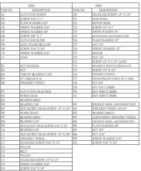
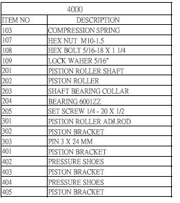
41 Exploded view drawings. 41
42 42
43 43
44 44
45 45
46 46
47 47
48 48
49 49
50 50
51 51
52 52
53 53

54 54
55 55
56 56
57 57
58 58
59 59
60 60
Laguna Tools 30" Wide belt Sander MWB " Wide Belt Sander MWB
 Laguna Tools 30" Wide belt Sander MWB2025-0320 38" Wide Belt Sander MWB3050-0320 Dear Woodworker: Thank you for your purchase and welcome to the Laguna Tools group of discriminating woodworkers. I understand
CIRCULATOR 1400 MDCCIRC OPERATING MANUAL
 C IRCULATOR Air Filtration System Manual CIRCULATOR 1400 MDCCIRC1400-0145 OPERATING MANUAL 17101 Murphy Avenue. Irvine, California 92614 www.lagunatools.com 800.234.1976 Dear Woodworker: Thank you for
Widebelt Sander Manual Model 25" & 37" Widebelt Sander
 Widebelt Sander Manual Model 25" & 37" Widebelt Sander LAGUNA TOOLS 2072 Alton Parkway Irvine, California 92606 Ph: 800.234.1976 www.lagunatools.com Part No. MSANWB25X60-1K-7.5-0197 Part No. MSANWB37X60-1K-15-0197
MOBILE BASE FOR THE REVO LATHE
 MOBILE BASE FOR THE REVO 18 36 LATHE LAGUNA TOOLS 2072 Alton Parkway Irvine, California 92606 Ph: 800.234.1976 www.lagunatools.com 2018, Laguna Tools, Inc. LAGUNA and the LAGUNA Logo are the registered
ES-125 EXTREMA MACHINERY COMPANY, INC. PO BOX 1450, ALBANY, LOUISIANA (877) (225)
 (225)") ES-125 EXTREMA MACHINERY COMPANY, INC. PO BOX 1450, ALBANY, LOUISIANA 70711 (877) 3987362 (225) 567-3867 TABLE OF CONTENTS General Safety Rules 2 Shipping & Receiving Instructions 3 Unpacking & Checking
ES-125 EXTREMA MACHINERY COMPANY, INC. PO BOX 1450, ALBANY, LOUISIANA 70711 (877) 3987362 (225) 567-3867 TABLE OF CONTENTS General Safety Rules 2 Shipping & Receiving Instructions 3 Unpacking & Checking
Powermatic Wide Belt Sander
 OPERATING PROCEDURE FOR: Powermatic 16-32 Wide Belt Sander INTRODUCTION: The wide belt sander is a very valuable tool. It can be used to quickly sand boards up to 32 wide, and provide an exceptional finish.
B DUAL DRUM SANDER
 OWNER S MANUAL B2022-25 DUAL DRUM SANDER INDEX GENERAL SAFETY INSTRUCTIONS Page 3 Specifications Page 4 Features Page 5 Assembly Instructions Initial Assembly Page 6 Installing Abrasives Page 7 Adjusting
Cyclone 600 Upcut Cut Off Saw
 Cyclone 600 Upcut Cut Off Saw WARNING The operator must thoroughly read and understand this manual before operating the cut off saw or starting any servicing. All safety and warning instructions should
6 Litre Oil-Less Air Compressor
 Operator s Manual 6 Litre Oil-Less Air Compressor WARNING! Before using this appliance, read the Operator s manual and follow all its safety rules and instructions. SPECIFICATION HWKAC1 1.1 kw / 1.5 HP
HEAVY DUTY TROLLEY JACK. Operation Manual
 HEAVY DUTY TROLLEY JACK 4T Operation Manual Make sure to read and fully understand the instruction manual before using this product and keep the manual properly 1 General Description Product Description
AUTOMATIC FOODSERVICE EQUIPMENT. AUTOMATIC ELECTRIC BROILER MODELS 824E & 850E and 624E & 650E. B-Series Broiler OWNER S MANUAL
 AUTOMATIC FOODSERVICE EQUIPMENT AUTOMATIC ELECTRIC BROILER MODELS 824E & 850E and 624E & 650E B-Series Broiler OWNER S MANUAL FOR YOUR SAFETY: Do not store or use gasoline or other flammable vapors or
Original. User Manual & Install Guide. Safe-T-Pull Inc. Page 1 of 15
 Original User Manual & Install Guide Safe-T-Pull Inc. Page 1 of 15 TABLE OF CONTINENTS 1. Before You Begin...3 Disclaimer...3 What Is Included...3 Claims...3 Contact Us...4 Safety Notes...4 2. Introduction...5
H-2034, H-2035 SHRINK TUNNEL
 H-2034, H-2035 SHRINK TUNNEL SPECIFICATIONS IMPORTANT! Read this manual thoroughly and familiarize yourself with ALL controls and operating features. Keep this manual for future reference and maintenance.
Pro. User Manual. Safe-T-Pull Inc Page 1 of 19
 Pro User Manual Safe-T-Pull Inc. 2015 Page 1 of 19 TABLE OF CONTINENTS 1. Before You Begin...3 Disclaimer...3 What Is Included...3 Unpacking Instructions....4 Claims...4 Contact Us...4 Safety Information...4
Maintenance and Repair
 Maintenance and Repair WARNING ALWAYS shut off the engine, remove key from ignition, make sure the engine is cool, and disconnect the spark plug and positive battery terminal from the battery before cleaning,
OPERATION MANUAL MODELS TWE-250 TWE-321 TWE-375 TRU WELD EQUIPMENT COMPANY 6400 N. HONEYTOWN ROAD SMITHVILLE, OHIO (330)
") OPERATION MANUAL MODELS TWE-250 TWE-321 TWE-375 TRU WELD EQUIPMENT COMPANY 6400 N. HONEYTOWN ROAD SMITHVILLE, OHIO 44677 (330) 669 2773 CONTENTS Section Description Pages 1 Introduction 3 2 External Features
OPERATION MANUAL MODELS TWE-250 TWE-321 TWE-375 TRU WELD EQUIPMENT COMPANY 6400 N. HONEYTOWN ROAD SMITHVILLE, OHIO 44677 (330) 669 2773 CONTENTS Section Description Pages 1 Introduction 3 2 External Features
NSGV PT-1000 PORTABLE WELDING STATION I, O & M MANUAL
 APPLICATION OF DUST CONTROL EQUIPMENT: CAUTION - Warning Improper operation of dust control system may contribute to conditions in the work area or facility that could result in severe personal injury
AIR COMPRESSOR OPERATING INSTRUCTION AND PARTS LIST
 AIR COMPRESSOR OPERATING INSTRUCTION AND PARTS LIST BELT TYPE IMPORTANT PLEASE MAKE CERTAIN THAT THE PERSON WHO IS TO USE THIS EQUIPMENT CAREFULLY READS AND UNDERSTANDS THESE INSTRUCTIONS BEFORE STARTING
Safety, Operation and Maintenance Instructions For Long & Short Nose Upholstery Air Stapler (NS10 & NS11)
") Safety, Operation and Maintenance Instructions For Long & Short Nose Upholstery Air Stapler (NS10 & NS11) Important: Drop 3 drops of oil into the stapler air inlet BEFORE first use. See page 2. Please
Safety, Operation and Maintenance Instructions For Long & Short Nose Upholstery Air Stapler (NS10 & NS11) Important: Drop 3 drops of oil into the stapler air inlet BEFORE first use. See page 2. Please
Grind Pro Series. Operator Manual. Manufacture by:
 Grind Pro Series Operator Manual Manufacture by: 1 Bench Sander Series INTRODUCTION The Bench Sander series are compact, durable machine designed for fast, complete finishing work. It will deliver efficient,
Raydot LLC 24 Actuator (115 VOLT)
") Installation, Operation & Parts Manual Read carefully the information provided. Retain manual for future reference. Raydot LLC 24 Actuator (115 VOLT) 145 Jackson Ave. S. Cokato, MN 55321-USA (320) 286-2103
Installation, Operation & Parts Manual Read carefully the information provided. Retain manual for future reference. Raydot LLC 24 Actuator (115 VOLT) 145 Jackson Ave. S. Cokato, MN 55321-USA (320) 286-2103
MODEL MC1500 Installation and Operation Manual Important:
 MODEL MC1500 Installation and Operation Manual Important: This manual contains specific cautionary statements relative to worker safety. Read this manual thoroughly and follow as directed. It is impossible
FTFR Maintenance and Parts Manual SQ-1 FLOOR TRUSS FINISH ROLLER. Operators Manual
 FTFR Maintenance and Parts Manual SQ-1 FLOOR TRUSS FINISH ROLLER Operators Manual FOREWORD This manual explains the proper maintenance of Square 1 Design Floor Truss Finish Roller as well as the daily
BOLT-ON AND WELD-ON FLUSH FLOOR SLIDEOUT SYSTEMS OPERATION AND SERVICE MANUAL
 BOLT-ON AND WELD-ON FLUSH FLOOR SLIDEOUT SYSTEMS OPERATION AND SERVICE MANUAL TABLE OF CONTENTS SYSTEM...... Warning........ Description...... Prior to Operation OPERATION... Main Components... Mechanical...
OPERATIONS MANUAL LEVER CHAIN HOIST
 OPERATIONS MANUAL LEVER CHAIN HOIST IMPORTANT SAFETY INFORMATION Please read, understand and follow all safety information contained in these instructions prior to the use of this hoist. Retain these instructions
Troubleshooting Guide: 355 Lights (12V)
") Troubleshooting Guide: 355 Lights (12V) Contents Description Refer To: Troubleshooting - Troubleshooting Chart Adjustments / Repair Procedures Bulb Replacing the Bulb Fuse(s) Replacing the Fuse (Ceiling)
Troubleshooting Guide: 355 Lights (12V) Contents Description Refer To: Troubleshooting - Troubleshooting Chart Adjustments / Repair Procedures Bulb Replacing the Bulb Fuse(s) Replacing the Fuse (Ceiling)
24 Linear Actuator 115 Volts A.C. (Cat. # C430A)
") Installation, Operation & Parts Manual Read carefully the information provided. Retain manual for future reference. 24 Linear Actuator 115 Volts A.C. (Cat. # C430A) Page 1 of 8 IS10007.doc 11/15/06 IMPORTANT!
Installation, Operation & Parts Manual Read carefully the information provided. Retain manual for future reference. 24 Linear Actuator 115 Volts A.C. (Cat. # C430A) Page 1 of 8 IS10007.doc 11/15/06 IMPORTANT!
CRD610 Automatic Fitting Inserter
 CRD610 Automatic Fitting Inserter OPERATIONS MANUAL VERSION 1.2 LAST EDITED 12.12.2018 cleanroomdevices.com 1 Table of Contents Title Page. 1 Table of Contents...2 1.0 General Product & Safety Information....3
AUTOMATIC FOODSERVICE EQUIPMENT. AUTOMATIC ELECTRIC BROILER MODELS 952E, 932E and 922E OWNER S MANUAL
 AUTOMATIC FOODSERVICE EQUIPMENT AUTOMATIC ELECTRIC BROILER MODELS 952E, 932E and 922E OWNER S MANUAL IMPORTANT: RETAIN THIS MANUAL IN A SAFE PLACE FOR FUTURE REFERENCE. FOR YOUR SAFETY: Do not store or
Champion Chippers OPERATOR S MANUAL. Operation & Safety. Includes Model: CX850 CX851. Part #
 OPERATOR S MANUAL Champion Chippers Operation & Safety Includes Model: CX850 CX851 Part # 990026 YOU MUST FILL OUT YOUR WARRANTY REGISTRATION TO ACTIVATE YOUR WARRANTY AND TO QUALIFY FOR PARTS SERVICE!!
2 TON CAPACITY PROFESSIONAL SERIES ALUMINUM JACK OWNER'S MANUAL SPECIFICATIONS
 80006 OWNER'S MANUAL CONTENTS: Page 1 Specifications 2 Warning Information 3 Setup, Operating and Preventative Maintenance 4 Troubleshooting 5 Maintenance 6 Exploded View Drawing and Replacement Parts
CHEMINSTRUMENTS HOT ROLL LAMINATOR MODEL HL-100, HL-101 OPERATING INSTRUCTIONS
 CHEMINSTRUMENTS HOT ROLL LAMINATOR MODEL HL-100, HL-101 OPERATING INSTRUCTIONS PRODUCT DESCRIPTION...2 SPECIFICATIONS...3 UNPACKING...3 ASSEMBLY...3 Key Components...5 SAFETY FEATURES...7 Trip Wire...7
Operating Instructions and Parts Manual 16-inch Open-End Belt Sander Model 1632
 Operating Instructions and Parts Manual 16-inch Open-End Belt Sander Model 1632 Powermatic 427 New Sanford Road LaVergne, Tennessee 37086 Part No. M-0460219 Ph.: 800-274-6848 Revision H2 01/2017 www.powermatic.com
Sofa Slideout Assembly OWNER'S MANUAL. Rev: Page 1 Sofa Slideout Owners Manual
 Sofa Slideout Assembly OWNER'S MANUAL Rev: 06.14.2016 Page 1 Sofa Slideout Owners Manual TABLE OF CONTENTS Warning, Safety, and System Requirement Information 3 Product Information 3 Prior to Operation
Heavy Duty Four Wheeled Walker
 Heavy Duty Four Wheeled Walker Weight Capacity: 500 lbs. ITEM # W1802 Made in China 2011 ESSENTIAL MEDICAL SUPPLY, INC. Manufactured for Orlando, FL 32822 -- SAVE THESE INSTRUCTIONS -- Do not attempt to
DIAMOND CONCRETE SAW MODEL CC1800XL P R O D U C T S OPERATOR S MANUAL. February Part #
 DIAMOND P R O D U C T S OPERATOR S MANUAL CONCRETE SAW MODEL CC1800XL February 2007 Part #1801038 Intentionally Blank GENERAL SAFETY WARNINGS AND PRECAUTIONS PERSONAL SAFETY Read and understand all operating
DAKE / JOHNSON VERTICAL BAND SAW
 DAKE / JOHNSON VERTICAL BAND SAW Model F - 6 INSTRUCTION MANUAL MODEL:F-6 SERIAL NUMBER: DATE PURCHASED: Need band saw blades? Call Dake DAKE (Division of JSJ) 724 Robbins Road Grand Haven, Michigan 4947
Troubleshooting Guide: 355 Lights (24V)
") Troubleshooting Guide: 355 Lights (24V) Contents Description Refer To: Troubleshooting - Troubleshooting Chart Adjustments / Repair Procedures Bulb Replacing the Bulb Fuse(s) Replacing the Fuse (Ceiling)
Troubleshooting Guide: 355 Lights (24V) Contents Description Refer To: Troubleshooting - Troubleshooting Chart Adjustments / Repair Procedures Bulb Replacing the Bulb Fuse(s) Replacing the Fuse (Ceiling)
OPERATION MANUAL. TWE Pin Welder. Model TWP-2 TRU WELD EQUIPMENT COMPANY 6400 N. HONEYTOWN ROAD SMITHVILLE, OHIO (330) Revision 2.
 Revision 2.") OPERATION MANUAL TWE Pin Welder Model TWP-2 TRU WELD EQUIPMENT COMPANY 6400 N. HONEYTOWN ROAD SMITHVILLE, OHIO 44677 (330) 725 7744 Revision 2.0 8/22/2013 TRU WELD EQUIPMENT LIMITED WARRANTY All goods
OPERATION MANUAL TWE Pin Welder Model TWP-2 TRU WELD EQUIPMENT COMPANY 6400 N. HONEYTOWN ROAD SMITHVILLE, OHIO 44677 (330) 725 7744 Revision 2.0 8/22/2013 TRU WELD EQUIPMENT LIMITED WARRANTY All goods
SANDERS AND ABRASIVES
 22-44 PLUS DRUM SANDER Our EXCLUSIVE SandSmart infinitely variable-feed control produces the ultimate finish at a rate from 0 to 10 feet per minute and prevents machine overload Patented conveyor belt
Hydraulic Wheel Dolly
 Hydraulic Wheel Dolly Operating Instructions & Parts Manual Model Number HW93766 Capacity 3/4 Ton Made in the U.S.A. This is the safety alert symbol. It is used to alert you to potential personal injury
READ AND SAVE THESE INSTRUCTIONS. Centrifugal Downblast Exhaust Fan Belt Driven for Roof & Wall Mounting
 READ AND SAVE THESE INSTRUCTIONS INSTALLATION, OPERATING INSTRUCTIONS & PARTS MANUAL Centrifugal Downblast Exhaust Fan Belt Driven for Roof & Wall Mounting Electrical wiring and connections should be done
SPECIFICATIONS CONTENTS:
 Model 3052 1,100 Lbs 2 Stage Transmission Jack INSTRUCTION MANUAL CONTENTS: Page 1 Specifications Page 2 Warning Information Page 3 Assembly Page 4 Operating Instructions Page 4 Preventative Maintenance
Embedded Rack Slide-out System
 Embedded Rack Slide-out System SERVICE MANUAL Rev: 02.16.2017 Page 1 Electric Embedded Rack Slide-out System TABLE OF CONTENTS Safety Information 3 Product Information 3 Operation 4 Extending Slide-Out
SELF PRIMING CHEMICAL SERVICE PUMPS
 SELF PRIMING CHEMICAL SERVICE PUMPS INSTALLATION AND OPERATING INSTRUCTIONS This Manual covers: SELF PRIMING MODEL RANGE J50ECX TO J250ECX STAINLESS STEEL*, and NON METALLIC SEAL PUMP MODEL: SERIAL NO:
CRD600 Automatic Fitting Inserter
 CRD600 Automatic Fitting Inserter OPERATIONS MANUAL VERSION 2.3 LAST EDITED 12.07.2018 cleanroomdevices.com 1 Table of Contents Title Page.. 1 Table of Contents. 2 1.0 General Product & Safety Information...3
SUNC1200 / ITEM #40882 SUBMERSIBLE UTILITY PUMP OPERATIONS MANUAL
 SUNC1200 / ITEM #40882 SUBMERSIBLE UTILITY PUMP OPERATIONS MANUAL WWW.SUNRUNNERPOOL.COM Performance Model HP GPH of Water @ Total Feet Of Lift 0 ft. 5 ft. 10 ft. 15 ft. 20 ft. 25 ft. Max. Lift SUNC1200
AIR/HYDRAULIC INJECTION GUN MODEL INSTRUCTIONS
 I. OPERATION & DESCRIPTION The Air / Hydraulic Injection Gun is a high-pressure tool that should be used with caution and according to these instructions. IMPORTANT: The Gun is 0,000 psi rated. Do not
OPERATION MANUAL MODELS TWE-250 TWE-321 TWE-375 TRU WELD EQUIPMENT COMPANY 6400 N. HONEYTOWN ROAD SMITHVILLE, OHIO (330)
") OPERATION MANUAL MODELS TWE-250 TWE-321 TWE-375 TRU WELD EQUIPMENT COMPANY 6400 N. HONEYTOWN ROAD SMITHVILLE, OHIO 44677 (330) 669 2773 Version 1.3 Date 10/20/2010 TRU WELD EQUIPMENT LIMITED WARRANTY All
OPERATION MANUAL MODELS TWE-250 TWE-321 TWE-375 TRU WELD EQUIPMENT COMPANY 6400 N. HONEYTOWN ROAD SMITHVILLE, OHIO 44677 (330) 669 2773 Version 1.3 Date 10/20/2010 TRU WELD EQUIPMENT LIMITED WARRANTY All
3 Ton Trolley Jack. Please read and fully understand the instructions in this manual before operation. Keep this manual safe for future reference.
 Please dispose of packaging for the product in a responsible manner. It is suitable for recycling. Help to protect the environment, take the packaging to the local amenity tip and place into the appropriate
User s Manual D-Series Blowers and Exhausters
 User s Manual D-Series Blowers and Exhausters D05-1 ½ HP TEFC 115/230 VOLTS, 1 PH D05-3 ½ HP TEFC 208/230/460 VOLTS, 3 PH D10-1 1 HP TEFC 115/230 VOLTS, 1 PH D10-3 1 HP TEFC 208/230/460 VOLTS, 3 PH D15-1
PRODUCT OPERATING MANUAL
 PRODUCT OPERATING MANUAL PANBLAST TM CS37 SUCTION BLAST CABINET Manual Number: ZVP PC 0069 00 SECTION 1. GENERAL INFORMATION 2. ASSEMBLY & INSTALLATION INSTRUCTIONS 3. OPERATING INSTRUCTIONS 4. MAINTENANCE
6722 Rev. A CAPACITY: 22 TON TRUCK AXLE JACK WITH AIR RETURN
 CONTENTS: Page Specifications 2 Warning Information Setup Instructions and Operating Instructions 4 Preventative Maintenance, Inspection and Proper Storage 5 Troubleshooting, Owner/User Responsibility
Snapshot LX5 USER MANUAL. OK on Dimmer Outdoor OK Sound Activated DMX512 Master/Slave 115V/230V Switch Replaceable Fuse User Serviceable Duty Cycle
 LX5 Snapshot OK on Dimmer Outdoor OK Sound Activated DMX512 Master/Slave 115V/230V Switch Replaceable Fuse User Serviceable Duty Cycle USER MANUAL Chauvet, 5200 NW 108th Avenue, Sunrise, FL 33351 U.S.A.
M-3025CB-AV Fuel Pump
 SAVE THESE INSTRUCTIONS M-3025CB-AV Fuel Pump Owner s Manual TABLE OF CONTENTS General Information... 2 Safety Instructions... 2 Installation... 3 Operation... 4 Maintenance... 4 Repair... 5 Troubleshooting...
6L Oil-less Air Compressor 53103
 6L Oil-less Air Compressor 53103 Operating Instructions Please read and save these instructions before attempting to assemble, install, operate or maintain the product. Protect yourself and others by observing
OLYMPIAN MODEL 740 Operation and Service Manual
 OLYMPIAN MODEL 740 Operation and Service Manual P/N 133911-102 FCI MANUAL P/N 133865-001 Data herein has been verified and validated and believed adequate for the intended use. If the machine or procedures
Diaphragm Valves Type 15
 Serial No. H-V031-E-8 Diaphragm Valves Type 15 User s Manual Contents (1) Be sure to read the following warranty clauses of our product 1 (2) General operating instructions 2 (3) General instructions for
D-Series Blowers and Exhausters
 Operation and Maintenance Manual D-Series MONOXIVENT - SOURCE CAPTURE SYSTEMS - info@ Oct. - 2015 MONOXVENT BLOWERS AND EXHAUSTERS D05-1 D05-3 D10-1 D10-3 D15-1 D15-3 D20-1 D20-3 D30-1 D30-3 ½ HP TEFC
SPECIFICATIONS SPECIFICATIONS
 4430 and 4450 OWNER'S MANUAL CONTENTS: Page 1 Specifications 2 Warning Information 3 Setup and Operating Instructions 4 Preventative Maintenance and Troubleshooting 5 4430 Exploded View Drawing and Parts
DISC BRAKE CALIPER TOOL SET
 DISC BRAKE CALIPER TOOL SET 40732 ASSEMBLY AND OPERATING INSTRUCTIONS Diagrams within this manual may not be drawn proportionally. Due to continuing improvements, actual product may differ slightly from
POWER PINNER CD HAND WELDER 7300 OPERATOR S MANUAL
 POWER PINNER CD HAND WELDER 7300 OPERATOR S MANUAL Copyright: April 7, 2014 Gripnail Corporation Revised: January 25, 2018 An Employee Owned Company 97 Dexter Road East Providence, Rhode Island 02914-2045
SPECIFICATIONS CONTENTS:
 Model 3052A 1,100 Lbs Air Assist 2 Stage Transmission Jack INSTRUCTION MANUAL CONTENTS: Page 1 Specifications Page 2 Warning Information Page 3 Assembly Page 4 Operating Instructions Page 4 Preventative
CLEAN ROOM DEVICES, LLC "WHERE TUBING AND FITTINGS COME TOGETHER"
 CLEAN ROOM DEVICES, LLC "WHERE TUBING AND FITTINGS COME TOGETHER" CRD600AF Automatic Fitting Inserter With Auto Feed OPERATIONS MANUAL (Shown with optional alcohol dispenser) 1 VERSION 1.1 LAST EDITED
Cordless two speed drill/driver K 10613
 Cordless two speed drill/driver K 10613 SAFETY AND PRECAUTION 1 Consider work area environment. Do not expose tools to rain. Do not use tools in damp or wet locations Keep work area clean and well lit.
Tooling Assistance Center
 Safeguards are designed into this application equipment to protect operators and maintenance personnel from most hazards during equipment operation. However, certain safety precautions must be taken by
SPECIFICATIONS Horsepower: 1.5 HP Running Maximum PSI: 125 PSI Tank Capacity: 15 Gallons CFM: 6 40 PSI 5 90 PSI
 15 GALLON AIR COMPRESSOR Model: 7678 DO NOT RETURN TO STORE Please call 800-348-5004 for parts and service CALIFORNIA PROPOSITION 65 WARNING: You can create dust when you cut, sand, drill or grind materials
COOKSON OWNER'S MANUAL
 COOKSON OWNER'S MANUAL FDO-A10 INDUSTRIAL DUTY FIRE DOOR OPERATOR R L I S T E D 3040233 US CONTROL PANEL SERIAL# OPERATOR SERIAL# 9001.DWG ECN 0959 REV 4 SPECIFICATIONS MOTOR TYPE:...INTERMITTENT HORSEPOWER:...1/8
OWNER S MANUAL SUBMERSIBLE UTILITY PUMP
 Model 51101-0 OWNER S MANUAL SUBMERSIBLE UTILITY PUMP Questions, problems, missing parts? Before returning to the store call AQUAPRO Customer Service 8 a.m. - 5 p.m., EST, Monday-Friday 1-844-242-2475
OWNER S MANUAL SELF-PRIMING PORTABLE UTILITY PUMP
 Model 54011-0 OWNER S MANUAL SELF-PRIMING PORTABLE UTILITY PUMP Questions, problems, missing parts? Before returning to the store call AQUAPRO Customer Service 8 a.m. - 5 p.m., EST, Monday-Friday 1-844-242-2475
450 Series Belt Driven Live Roller Curve Conveyor Installation and Maintenance Manual
 450 Series Belt Driven Live Roller Curve Conveyor Installation and Maintenance Manual Metzgar Conveyor Co. - 2010 METZGAR CONVEYORS SAFETY PRECAUTIONS WARNING: DO NOT ATTEMPT MAINTENANCE ON ANY CONVEYORS
Wood Chipper Model C550M Operator's Manual
 Wood Chipper Model C550M Operator's Manual THIS MANUAL MUST BE READ AND UNDERSTOOD BEFORE ANYONE OPERATES THIS MACHINE! Manual# 990023 Revised 01/2010 YOU MUST FILL OUT YOUR WARRANTY REGISTRATION TO ACTIVATE
Installation / Operating Manual. Infinity Series Model AS2002. Distributed by: Shyda s Services Inc.
 Installation / Operating Manual Infinity Series Model AS2002 Distributed by: Shyda s Services Inc. WARRANTY: INFINITY SERIES MODEL AS2002 For two(2) years from the original date of purchase, Lincoln Traps
A2P Single Phase Automatic Industrial Battery Charger
 A2P Single Phase Automatic Industrial Battery Charger Featuring 205B Konrad Cres., Markham, ON, L3R 8T9 www.chargers.ca Building Canada s toughest battery chargers for over a century. Congratulations on
3 TONNE TROLLEY JACK
 3 TONNE TROLLEY JACK 16407 These instructions accompanying the product are the original instructions. This document is part of the product, keep it for the life of the product passing it on to any subsequent
SIP Direct Drive Oil-Lube Air Compressors - Operating & Maintenance Instructions
 SIP Direct Drive Oil-Lube Air Compressors - Operating & Maintenance Instructions Please read and fully understand the instructions in this manual before operation. Keep this manual safe for future reference.
jegs.com. Installation Instructions for Ton Aluminum Floor Jack
 Installation Instructions for 80077 3-Ton Aluminum Floor Jack Contents: Specifications Warning Information Setup and Operating Instructions Preventive Maintenance and Troubleshooting Hydraulic Maintenance
750 Series Press Conveyor Installation and Maintenance Manual
 750 Series Press Conveyor Installation and Maintenance Manual Metzgar Conveyor Co. - 2010 METZGAR CONVEYORS SAFETY PRECAUTIONS WARNING: DO NOT ATTEMPT MAINTENANCE ON ANY CONVEYORS WHILE IN OPERATION. BEFORE
Radian Research, Inc. makes no warranty on the accuracy of the information contained in this Operations Manual and accepts no liability for its use.
 About This Operations Manual makes no warranty on the accuracy of the information contained in this Operations Manual and accepts no liability for its use. The information contained in this Operations
Marzocchi Suspension MZ III MZ III. Technical instructions
 Technical instructions Exploded view - MZ III - 100 Rif. Code Quantity Spare part list - MZ III - 100 Rif. Code Description Q.ty in the model Technical characteristics: Technical characteristics Single-crown
Introduction. Notes. Your Baker P.A.Q. Band Resaw has been designed to be sturdy, simple, and easy to use.
 Contents I n t r o d u c t i o n...................................................................................................................... 2 W a r r a n t y............................................................................................................................
Performance Brake Caliper Guide Bushing Set Installation Guide
 Performance Brake Caliper Guide Bushing Set Installation Guide Proper service and repair procedures are vital to the safe, reliable operation of all motor vehicles as well as the personal safety of those
WALKING TREADMILL SF-T1407M USER MANUAL
 WALKING TREADMILL SF-T1407M USER MANUAL IMPORTANT! Please retain owner s manual for maintenance and adjustment instructions. Your satisfaction is very important to us, PLEASE DO NOT RETURN UNTIL YOU HAVE
DC TO AC POWER INVERTER PWRIC150012W INSTRUCTION MANUAL
 DC TO AC POWER INVERTER PWRIC150012W INSTRUCTION MANUAL SAVE THIS MANUAL You will need the manual for the safety warnings and precautions, assembly instructions, operating and maintenance procedures, parts
MODEL RF. Drain Cleaning Machine. Operator s Manual
 MODEL RF Drain Cleaning Machine Operator s Manual!!!! FOR YOUR SAFETY Before you operate or maintenance this equipment, READ this manual carefully and completely! The Electric Eel Model RF Drain Cleaning
Perfmaster Air V3. Serial Number. Date
 Perfmaster Air V3 12-2015 Serial Number Date TABLE OF CONTENTS SPECIFICATIONS.3 SAFETY PROCEDURES/CARE & MAINTENANCE..4 COMPONENT IDENTIFICATION 5 DELIVERY TRAY ASSEMBLY.6 PAPER STOP ASSEMBLIES..7 MACHINE
GRSM17 Pneumatic Center Punch Tool Owner s Manual and Operating Instructions
 Owner s Manual and Operating Instructions Table of Contents Page Information 2 Safety Guidelines and Warranty 3 Overview and Installation 4 Air System Requirements 5 Setting Controls 6 Installing Clamps
PHANTOM (PH10 and PH12) COMMERCIAL AND INDUSTRIAL SERIES
 COMMERCIAL AND INDUSTRIAL SERIES") Document No: ICM-IOM Date: 0411 PHANTOM (PH10 and PH12) COMMERCIAL AND INDUSTRIAL SERIES Installation, Operation and Maintenance Manual Please read and save these instructions. Read carefully before attempting
Document No: ICM-IOM Date: 0411 PHANTOM (PH10 and PH12) COMMERCIAL AND INDUSTRIAL SERIES Installation, Operation and Maintenance Manual Please read and save these instructions. Read carefully before attempting
Bucket Grease Pump ASSEMBLY AND OPERATING INSTRUCTIONS
 Bucket Grease Pump 9793 ASSEMBLY AND OPERATING INSTRUCTIONS 349 Mission Oaks Blvd., Camarillo, CA 930 Visit our Web site at http://www.harborfreight.com Copyright 2004 by Harbor Freight Tools. All rights
Positive Displacement Pump
 www.conairgroup.com U S E R G U I D E UGC028-1105 Positive Displacement Pump Models PD 3. 5, 7.5, 10, 15 and 25 Corporate Office: 724.584.5500 l Instant Access 24/7 (Parts and Service): 800.458.1960 l
Installation, Operating and Maintenance Instructions Retractable Door / Art.-Nr.:
 Installation, Operating and Maintenance Instructions Retractable Door 06.2008 / Art.-Nr.: 1 818 024 ENGLISH CONTENTS PAGE 1 SAFETY REQUIREMENTS 3 1.1 Symbols and key words used 3 1.2 Designated use 3 1.3
SHORT-STOP. Electronic Motor Brake Type G. Instructions and Setup Manual
 Electronic Motor Brake Type G Instructions and Setup Manual Table of Contents Table of Contents Electronic Motor Brake Type G... 1 1. INTRODUCTION... 2 2. DESCRIPTION AND APPLICATIONS... 2 3. SAFETY NOTES...
Val-Matic Air / Oil Hydraulic Panel Pump Control System. Operation, Maintenance and Installation Manual
 Manual No. 5AOP-OM1-2 Val-Matic Air / Oil Hydraulic Panel Pump Control System Operation, Maintenance and Installation Manual INTRODUCTION... 1 RECEIVING AND STORAGE... 1 DESCRIPTION OF OPERATION... 1 INSTALLATION...
AUTO REWIND AIR HOSE REEL
 Model #s 46845, 46848 AUTO REWIND AIR HOSE REEL OPERATOR S MANUAL STORE THIS MANUAL IN A SAFE PLACE FOR FUTURE REFERENCE!? NEED HELP? Save time, contact us first. 888-648-8665 support@tekton.com WARNING:
AIR CLEANERS Model MC 3000 OWNER S MANUAL CAUTION Read complete instructions before operating. Please file for future reference.
 AIR CLEANERS Model MC 3000 OWNER S MANUAL CAUTION Read complete instructions before operating. Please file for future reference. MODEL MC 3000 SPECIFICATION Input Volts: 208-230/430 VAC, 60Hz, 3 Phase
OPERATOR S MANUAL StudPro LiteXI Pin Welder Stud Welding Products, Inc
 OPERATOR S MANUAL StudPro LiteXI Pin Welder CONTENTS Description Pages Safety 2 Specifications and Features 3 Product Components 4-5 Screen Operation 6-8 Setup and Welding 9-11 CD Gun Exploded View 12
60 Series End-Mount Brake Instructions Standard Housing
 Bulletin No. BK4655 (04/18) 60 Series End-Mount Brake Instructions Standard Housing Read carefully before attempting to assemble, install, operate or maintain the product described. Protect yourself and
RolsplicerTM. Maintenance Manual And Illustrated Parts List
 RolsplicerTM Maintenance Manual And Illustrated Parts List List of Illustrations Figure Page. Rolsplicer 3 2. Roller Adjustment 4 3. Rolsplicer 6 4. Lid Hold Down Assembly 8 5. Automatic Lid Speed Adjustment
Breezair TBA 550 Installation Manual
 Breezair TBA 550 Installation Manual Table of Contents ITEM Safety Instructions Specifications Exploded View of the Air Cooler Components of the Air Cooler Dismantling the Air Cooler Installing the Transition
Marzocchi Suspension MZ I MZ I. Technical instructions
 Technical instructions Exploded view - MZ I - 100 Rif. Code Quantity Spare part list - MZ I - 100 Rif. Code Description Q.ty in the model Technical characteristics: Technical characteristics Single-crown