Positive Stop Control. Prod. No.: , Part No.: Dimensions: 12 1/4" wide x 6 1/4"deep x 17 3/4" high Weight: 57 lbs.
|
|
|
- Aubrie Sanders
- 6 years ago
- Views:
Transcription

1
2 Positive Stop Control Prod. No.: , Part No.: 77 Dimensions: 12 1/" wide x 6 1/"deep x 17 3/" high Weight: 57 lbs. (with stand) Pump Specifications All pumps maximum rated working pressure: 10,000 psi Shop Air Pump Prod. No.: , Part No.: 778 Weight: 10 lbs. 1/ H.P. 12 Volt DC Pump Prod. No.: , Part No.: 7739 Weight:.5 lbs. 1/2 H.P. 115 Volt AC Pump Prod. No.: , Part No.: 771 Weight: 32 lbs. Hand Pump Prod. No.: , Part No.: Weight: 25.6 lbs. 1/ H.P. 115 Volt AC Pump Prod. No.: , Part No.: 770 Weight: lbs. 1-1/2 H.P. 115 Volt AC Pump Prod. No.: , Part No.: 772 Weight: 108 lbs. Carefully read and understand the following warnings before operating this crimper. WARNING! An incorrect hose assembly can rupture or blow apart in use, resulting in serious injury, death or property damage. REMEMBER: Others depend on you to make correct assemblies. FOR SAFETY S SAKE USE THIS MACHINE ONLY IF YOU: 1. Receive hands-on TRAINING with the - and Gates assemblies. 2. Follow current GATES OPERATING MANUAL AND CRIMP DATA for the Use only NEW (UNUSED) GATES hose and fittings.. Wear SAFETY GLASSES. 5. KEEP HANDS CLEAR OF MOVING PARTS. Support hose with one hand while activating pump with other hand. 6. DO NOT operate pump UNLESS cylinder is locked in crimp position. 7. To avoid risk of injury, DO NOT use crimper UNLESS CONTROLLER BASE PLATE is in place. 8. DO NOT operate crimper in horizontal position.
3 Serial No. (Located on front top of cylinder) Date of Purchase Contents Identification List...2 Setup...3 Hose Preparation...6 Operating Instructions...8 Measuring and Adjusting the Crimp Diameter...12 Maintenance...13 Troubleshooting...1 Replacement Parts List...15 Warranty...inside back cover 1 1
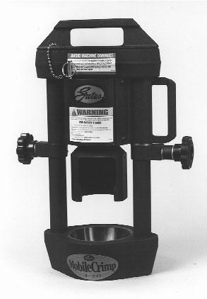


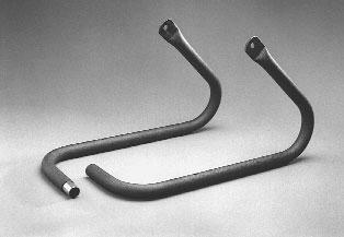
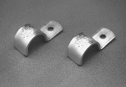
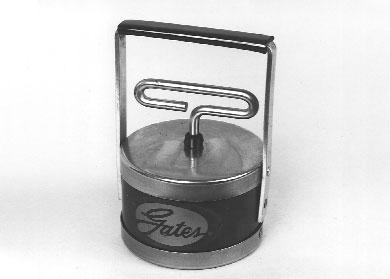
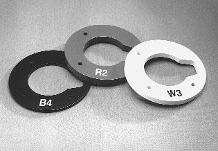

4 Identification List Spacer Rings Die Molykote and Brush Pressure Plate Stand Crimper Hose Assembly Clamps Literature Packet Magnet 2
, nylon-covered hose assembly (1), literature envelope (1), stand (2 pieces), magnet (1) and Molykote")

 with the handle to the")
5 Setup 1. Unpack carton. Remove crimper, pressure plate (1), nylon-covered hose assembly (1), literature envelope (1), stand (2 pieces), magnet (1) and Molykote lubricant (1) from shipping carton. Locate the serial number assigned to the crimper on the top front of the cylinder and record on page one for future reference. 2. Attach crimper to the stand. Place crimper on flat, well-supported surface (such as the top of a workbench or the bed of a service vehicle) with the handle to the right. Remove two (2) knobs, flat washers (2) and spacer (1) from crimper pivot bolts. Replace spacer, flat washers and knobs. Do not tighten knobs. Left Side spacer Right Side Lift crimper and allow stand to swing down onto the surface. Tighten knobs. Slide the two halves of the stand together and attach to the crimper at the pivot bolts. 3

. Pipe sealant may be used to seal connection.")
 Edge of work surface (2) 5 /16\" diameter holes 7 1 /2\" 11\" Drill two 5/16\" diameter holes.")

6 3. Fasten crimper to work surface before use (to avoid damage to machine or personal injury because an unsecured machine can fall). Position crimper so that mounting holes are approximately 7" to 8" from the edge of the work surface. Mark the drilling location using the mounting holes as a guide (see illustration below).. Attach pump to crimper. Place pump near crimper. Connect hose assembly to the pump port (3/8" NPT threads). Pipe sealant may be used to seal connection. (For best connection, use Gates Quick Disconnect couplings, G and G , sold separately.) Edge of work surface (2) 5 /16" diameter holes 7 1 /2" 11" Drill two 5/16" diameter holes. Use mounting holes or clamps to fasten stand to work surface. Connect opposite end to the adapter on crimper. clamps mounting holes 5. Check pump oil level. Pump comes with oil in reservoir. Check proper oil level per pump operating manual instructions or the Maintenance Section (p. 13) of this manual. To avoid damage to the machine or injury to you, ALWAYS fasten the crimper to the work surface before you attempt to crimp.
.")

 which extends the ram.")
7 6. Connect pump to power outlet. For 115V connection, plug power cord into a properly grounded and rated circuit (see inside cover for circuit requirements). For vehicle battery connection, see pump operating manual. 7. Bleed air from system. Tilt crimper forward so adapter is at its highest point. 8. Place crimper in comfortable working position. See photo below for suggested working position. IMPORTANT Do not operate crimper in horizontal position because dies will become unstable. Turn pump on by pressing and holding the power on switch, (see pump operating manual for switch location) which extends the ram. Note: It s a good idea to place a rubber mat on the floor near the crimper to reduce the chance of damaging a die if dropped and improve operator comfort. Extend the ram approximately 1". Release on switch allowing ram to fully retract. Repeat a minimum of five (5) times to bleed air completely. 5

, 28-7365 (Auto), select the correct coupling or visit our website to download our electronic program at www.gates.com/ecrimp. 3.")
8 Hose Preparation MegaCrimp Pre-Assembled Couplings. CAUTION A new hose and end fittings (stem/ferrule) must be used when building a hose assembly. Re-using any components will seriously affect performance and could result in serious injury or property damage.. Insert coupling into the hose until the mark lines up with the end of the coupling ferrule. 1. Cut hose to desired length. 2. Using Gates crimp data chart #35019 (Ind), (Auto), select the correct coupling or visit our website to download our electronic program at 3. Place a visible mark on hose cover at the insertion length shown on the crimp data chart. 5. Hose and coupling are now ready for crimping. 6
 must be used when building a hose assembly.")


9 GlobalSpiral Two-Piece Couplings. CAUTION Hose should be flush against stem shoulder (see cutaway drawing below). A new hose and end fittings (stem/ferrule) must be used when building a hose assembly. Re-using any components will seriously affect performance and could result in serious injury or property damage. 1. Cut hose to desired length. 2. Using Gates crimp data chart # (Ind), (Auto), select the correct stem and ferrule or visit our website to download our electronic program at 3. Place ferrule over end of hose.. Lubricate the first two or three serrations on stem with lightweight oil (SAE 10W). 5. Clamp stem in vise on hex portion, and push hose onto stem. 6. Hose and coupling are now ready for crimping. 7
, 28-7365 (Auto) or ecrimp, select correct die set for the hose and coupling")


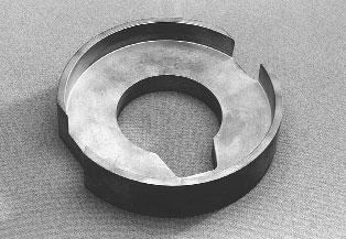
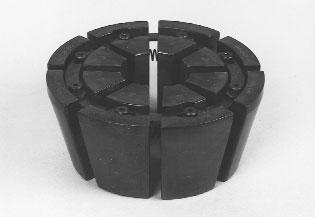
10 Operating Instructions 1. Select correct die set. Using Gates crimp data chart #35019 (Ind), (Auto) or ecrimp, select correct die set for the hose and coupling being crimped. Using the magnet, place the die set into the die cone. die set 2. Lubricate and load die. Swing cylinder to die loading position. Apply thin layer of Molykote* lube to the inside surface of the die cone. Re-apply lube whenever surface becomes shiny. Remove magnet by lifting the T handle, making sure the top of the die fingers are even. Apply a thin layer of Molykote lube to the top of the die set. Important Note: Lubricants should be reapplied to metal-tometal sliding surfaces whenever the surface becomes shiny. Failure to do this reduces the life of the dies and cone. Excessive wear on these components produces poorly performing hose assemblies that could blow apart and result in injury. * Use only Gates Molykote lube for proper operation or Gates-recommended grease. 8
, 28-7365 (Auto) or ecrimp, select correct")

11 3. Select correct spacer. Using Gates crimp data chart #35019 (Ind), (Auto) or ecrimp, select correct spacer for the hose and coupling being crimped.. Install spacer and pressure plate. Place the spacer into the pressure plate. spacer Place the pressure plate (with spacer) onto the die set. Spacer must be located between pressure plate and die set. 9


12 5. Insert hose assembly. Insert assembly from the bottom of the die cone up through the die set. When crimping bent tube and blockstyle couplings, keep thread end aligned with notch in pressure plate and spacer. Locate the top of the ferrule approximately 1/16"below the top of the die set. 6. Swing cylinder into crimping position. Using the handle, swing cylinder toward you and lock into place with lock pin. IMPORTANT For GS couplings, make sure the top of the ferrule rests against the hex or round shoulder of the coupling. 10


.")
13 Make sure cylinder is locked into position by placing lock pin into hole on top of cylinder. CAUTION Keep away from all moving parts! If bodily contact with a moving part occurs, immediately release the pump power on switch. lock pin IMPORTANT Serious injury and/or crimper damage can result if the cylinder is not locked in its crimp position. Incorrect Correct 7. Begin the crimp. Start pump by steadying hose with one hand while pressing and holding the power on switch with the other hand, which extends the ram (see pump operation manual for switch location). When pressure plate contacts the top of the die cone, release the power on switch. Crimp is now complete. 8. Remove hose assembly. While holding hose, lightly lift bottom of die set to release hose assembly. Remove hose assembly. 11
 measure halfway between ridges (Fig. 1). To be sure crimp diameter is being properly measured, mark a crimp flat. Beginning with that flat, count 9 flats to get the diameter.")
 which are notched to clear ridges, measure halfway between ridges (Sketch 1).")

14 Measuring and Adjusting the Crimp Diameter NOTE: DO NOT measure on top of part number stamps. 1. Measure the crimp diameter. When using 21 and 22 Dies Using Gates 21/22 dial calipers (Product No , Part No ) measure halfway between ridges (Fig. 1). To be sure crimp diameter is being properly measured, mark a crimp flat. Beginning with that flat, count 9 flats to get the diameter. Be sure caliper blades DO NOT touch ridges. (See Photo 3.) FIG. 1 Measure halfway between the ends of crimped portion of the ferrule (Fig. 2). When NOT using 21 and 22 Dies Using Gates dial calipers (Product No , Part No ) which are notched to clear ridges, measure halfway between ridges (Sketch 1). Be sure caliper fingers DO NOT touch ridges or part number stamps. (See Photo 3.) FIG. 2 CALIPER CRIMP DIA. SKETCH 1 RIDGES PHOTO 3 2. Check crimp diameter. The measured crimp diameter must be within 0.010"of the published crimp diameter. If not, the hose assembly cannot be used, and adjustment will be required. 3. Adjust the crimp diameter (if necessary). Check top of die set and the surfaces of the pressure plate for any debris (metal chips, dirt, etc.). Debris may cause some variation in crimp diameter. If necessary, clean the surfaces and lightly lubricate with Molykote.. Multiple crimps. When crimping multiple assemblies, check every tenth crimp to ensure diameter is within acceptable range (± 0.010"). Measure halfway down the crimped portion of the ferrule (Sketch 2). CRIMP DIA. 12 SKETCH 2
15 Maintenance This crimper requires minimal maintenance. However, the following practices are recommended to ensure maximum reliability and service. Lubricate. Using the small brush and Molykote, apply a light coat to the inside surface of the die cone whenever it becomes shiny. Check oil level. Check the hydraulic oil level in the pump reservoir after each 10 hours of use (see pump operation manual for instructions). If the oil is more than 1/2" below the top, add a high-grade hydraulic oil such as Mobil DTE 25 until within 1/2" of the top of the reservoir. Change the oil. (NOTE: Frequency depends on the pump s general working conditions, severity of use and overall cleanliness.) For general shop conditions, change oil every 300 hours. For field/mobile conditions, more frequent changes are required. Drain, clean and refill the reservoir per pump operating instructions with a high-grade hydraulic oil such as Mobil DTE 25 until within 1/2" of the top of the reservoir. Inspect the die links, springs and shoulder screws monthly to see if they are broken, cracked or missing. These conditions may affect crimp quality. Replace if necessary. Inspect hose assembly. Inspect hose assembly connecting the crimper and pump monthly (more often with severe use). Check nylon sleeve for cuts or abrasion. If sleeve is damaged, check hose for damage. If hose has any signs of damage, replace immediately. A damaged hose may rupture and cause serious injury. If hydraulic oil is present on the hose assembly, serious damage may exist. Replace immediately. Calibration. None required. Inspect die sets, pressure plate and spacers. Periodically inspect the surfaces of die sets, pressure plate and spacers for debris (metal chips, dirt, etc.) or damage. If debris is present, clean and lightly lubricate. If damaged, replacement is required (see parts list for ordering information). 13
16 Troubleshooting All equipment is tested for proper performance before it is shipped from the factory. However, if you experience any difficulties, check the list below to help restore equipment to proper operating standards. Problem Ram will not fully extend. Correction Check hydraulic oil level in pump reservoir. Hydraulic oil temperature must be within +0º F and +1º F. Ram will not retract. Unplug pump from electrical outlet. (WARNING: pump must be unplugged to avoid risk of injury.) Slowly and carefully loosen hose at pump. Be prepared to catch oil as it escapes. If ram retracts, pump valve may be stuck or need replacement. Pump motor will not start. Check electrical connections. 1
17 Replacement Parts List *Not shown 15 15
18 Two-Year Limited Warranty on Equipment For two years from the date of shipment of the equipment to the original user, The Gates Rubber Company will, at its option, replace or repair any unit which proves to be defective in material or workmanship, or both, at no cost to the original user of the equipment. This is the exclusive remedy. THERE IS NO OTHER EXPRESS OR IMPLIED WARRANTY. ALL INCLUDING THOSE OF MERCHANTABILITY AND FITNESS FOR A PARTICULAR PUR- POSE, ARE LIMITED TO ONE YEAR FROM DATE OF SHIPMENT OF THE EQUIPMENT TO THE ORIGINAL USER. LIABILITY FOR CONSEQUENTIAL AND INCIDENTAL DAM- AGES UNDER ANY AND ALL WARRANTIES IS EXCLUDED TO THE EXTENT EXCLU- SION IS PERMITTED BY LAW. Some states do not allow the exclusion of incidental or consequential damages, and some states do not allow limitations on how long an implied warranty lasts, so the above limitation and exclusion may not apply to you. This warranty gives you specific legal rights and you may also have other rights which vary from state to state. For warranty service, contact Service Department, The Gates Rubber Company, 990 S. Broadway, P.O. Box 5887, Denver, Colorado How to Order Repair Parts All parts for TM - machine listed in current replacement parts price sheets can be ordered directly from The Gates Rubber Company, Iola Distribution Center, 999 Michigan Ave., P.O. Box 606, Iola, KS 6679, Phone (316) When ordering, be sure to include the following information: 1. Name of unit shown on front. 2. Product number of parts needed. 3. Description of parts needed.. Quantity of parts needed. 5. Serial number of machine. For selling prices on inventoried parts, refer to Hydraulic Power Crimp Equipment and Parts List Price Schedule. Selling prices for parts not shown in these lists will be furnished on request, or parts will be shipped at prevailing prices and you will be billed accordingly. For information regarding prices, contact your local Gates representative or The Gates Rubber Company, 990 South Broadway, P.O. Box 5887, Denver, Colorado When returning inoperable equipment, contact your Gates sales representative and request a return goods authorization form. Fill out and send to: The Gates Rubber Company ATTN: Service Department Unit 29 Receiving 901 S. Broadway Denver, Colorado
19 The world s most trusted name in belts, hose and hydraulics. The Gates Rubber Company P.O. Box 5887 Denver, Colorado (Auto) PS (Ind) 9/02
Transmission Jacks. 1ZKY1 and 1ZKY3. Description. Specifications. Assembly
 Operating Instructions & Parts Manual Please read and save these instructions. Read carefully before attempting to assemble, install, operate or maintain the product described. Protect yourself and others
MODEL 7400 STRUT SPRING COMPRESSOR
 MODEL 7400 STRUT SPRING COMPRESSOR Installation, Operation & Repair Parts Information Branick Industries, Inc. 4245 Main Avenue P.O. Box 1937 Fargo, North Dakota 58103 REV112712 P/N: 81-0103A TABLE OF
MODEL 7600 STRUT SPRING COMPRESSOR
 MODEL 7600 STRUT SPRING COMPRESSOR Installation, Operation & Repair Parts Information Branick Industries, Inc. 4245 Main Avenue P.O. Box 1937 Fargo, North Dakota 58103 REV6162014 P/N: 81-0246 TABLE OF
UNIQUE USER FRIENDLY MICROMETER STYLE ADJUSTMENT
 The series hose crimper with Micrometer Style Adjustment and 35 tons of crimping force has the capability to crimp hoses up to " 2 wire and 3/4" 4 wire. UNIQUE USER FRIENDLY MICROMETER STYLE ADJUSTMENT
Page D165DC MARKIV OPERATORS MANUAL
 1 D165DC MARKIV OPERATORS MANUAL 2 WARNING - SAFETY NOTE IMPORTANT - DO NOT OPERATE THIS EQUIPMENT UNTIL YOU READ AND FULLY UNDERSTAND THIS MANUAL AND ITS ASSEMBLY INSTRUCTIONS ALWAYS WEAR EYE PROTECTION
CC30 Service Hose Crimper
 The CC30 Series hose crimper with the Micrometer er Style Adjustment and 55 tons of crimping force has the capability to crimp up to " 6 SP. UNIQUE USER FRIENDLY MICROMETER STYLE ADJUSTMENT Easy to use
Operating Instructions and Parts Manual AHR-50 Auto Rewind Hose Reel
 Operating Instructions and Parts Manual AHR-50 Auto Rewind Hose Reel JET 427 New Sanford Road LaVergne, Tennessee 37086 Part No. M-426238 Ph.: 800-274-6848 Revision C 04/2017 www.jettools.com Copyright
(Equipped with Bottle Jack)
") Operating Instructions & Parts Manual Please read and save these instructions. Read carefully before attempting to assemble, install, operate or maintain the product described. Protect yourself and others
Operating Instructions & Parts Manual Please read and save these instructions. Read carefully before attempting to assemble, install, operate or maintain the product described. Protect yourself and others
EU32 HYDRAULIC CRIMPER OPERATORS MANUAL
 EU32 HYDRAULIC CRIMPER OPERATORS MANUAL 2 SAFETY PRECAUTIONS READ INSTRUCTIONS AND IDENTIFY ALL COMPONENT P ARTS BEFORE USING CRIMPER CRIMPER CAN PRODUCE 55 TONS OF FORCE. KEEP BOTH HANDS AWAY FROM PINCH
CC15 Service Hose Crimper
 The CC15 Series hose crimper with the Micrometer er Style Adjustment and 33 tons of crimping force has the capability to crimp up to ½" 4SP. UNIQUE USER FRIENDLY MICROMETER STYLE ADJUSTMENT Easy to use
CONTENTS. VIKING PUMP, INC. A Unit of IDEX Corporation Cedar Falls, IA USA SECTION TSM 710.1
 TECHNICAL SERVICE MANUAL industrial heavy duty motor speed pumps SERIES 4076 AND 4176 SIZES hle, ate and ale SECTION TSM 710.1 PAGE 1 of 8 ISSUE B CONTENTS Introduction....................... 1 Safety
Operating Instructions & Parts Manual. Supa-Lite Lever Grease Gun. Model 48UJ77
 Operating Instructions & Parts Manual EN Supa-Lite Lever Grease Gun Model 48UJ77 PLEASE READ AND SAVE THESE INSTRUCTIONS. READ CAREFULLY BEFORE ATTEMPTING TO ASSEMBLE, INSTALL, OPERATE OR MAINTAIN THE
MODEL G300 BRAKE BLEEDER
 MODEL G300 BRAKE BLEEDER Installation, Operation & Repair Parts Information Branick Industries, Inc. 4245 Main Avenue P.O. Box 1937 Fargo, North Dakota 58103 REV120716 P/N: 81-0035H THIS PAGE INTENTIONALLY
Revised BX-1000 BLACK MAX
 Revised 8-22-12 BX-1000 BLACK MAX PLEASE READ THROUGH THE ENTIRE MANUAL BEFORE INSTALLING YOUR BRAKE SYSTEM WARNING - DO NOT USE BRAKE FLUID - USE ATF HYDRAULIC FLUID ONLY **IMPORTANT** DO NOT USE ANY
Air / Hydraulic Pump
 Form No. 538016 Parts List & Operating Instructions for: 2510A Original Instructions Air / Hydraulic Pump Maximum Capacity: 690 bar (10,000 psi) Description: The 2510A air/hydraulic pump is designed to
MODEL TC400 TIRE CART. Installation, Operation & Repair Parts Information REV P/N:
 MODEL TC400 TIRE CART Installation, Operation & Repair Parts Information REV061614 P/N: 81-0245 1 TABLE OF CONTENTS SAFETY INSTRUCTIONS 2 DEFINITIONS 2 SPECIFICATIONS 3 INSTALLATION INSTRUCTIONS 3 OPERATING
Nor East. Instructions Safety Messages. Inspection. Parts. DeZURIK Service. Type 05 Pneumatic Actuator Used With Globe Valves
 Instructions Safety Messages These instructions are intended for personnel who are responsible for installation, operation and maintenance of your DeZURIK Actuator. All safety messages in the instructions
MODEL L/R/EF Sectional Tire Spreader
 MODEL L/R/EF Sectional Tire Spreader Installation, Operation & Repair Parts Information Branick Industries, Inc. 4245 Main Avenue P.O. Box 1937 Fargo, North Dakota 58103 REV08032016 P/N: 81-0195E TABLE
Air Actuated Hydraulic Bottle Jack on Wheels
 Operating Instructions & Parts Manual Air Actuated Hydraulic Bottle Jack on Wheels Model Number 18127 18207 Capacity 12 Ton 20 Ton Shinn Fu Co. of America, Inc. 2002 10939 N. Pomona Avenue Kansas City,
TECHNICAL SERVICE MANUAL
 Electronic copies of the most current TSM issue can be found on the Viking Pump website at www.vikingpump.com TECHNICAL SERVICE MANUAL SECTION TSM 610 Viking Helical Gear Reducers a, b, and c sizes PAGE
TECHNICAL SERVICE MANUAL
 Electronic copies of the most current TSM issue can be found on the Viking Pump website at www.vikingpump.com TECHNICAL SERVICE MANUAL VIKING HELICAL GEAR REDUCERS A, B, AND C SIZES SECTION PAGE ISSUE
Hydraulic Wheel Dolly
 Hydraulic Wheel Dolly Operating Instructions & Parts Manual Model Number HW93766 Capacity 3/4 Ton Made in the U.S.A. This is the safety alert symbol. It is used to alert you to potential personal injury
Maintenance Information
 16573321 Edition 3 February 2014 Air Grinder Series 61H Maintenance Information Save These Instructions Product Safety Information WARNING Failure to observe the following warnings, and to avoid these
Model 80 & 80E Actuator* for Trailer Brakes 8000 lbs Capacity Part #47206/ Drum Brake Ready Part #47208/ Disc Brake Ready
 Installation Instructions and Service Manual For Serial Numbers 6020 and above. Model 80 & 80E Actuator* for Trailer Brakes 8000 lbs Capacity Part #47206/47207 - Drum Brake Ready Part #47208/47209 - Disc
Aeroquip ProCrimp 1370 Crimp Machine Operator s Manual
 FT1370-500 Aeroquip ProCrimp 1370 Crimp Machine Operator s Manual Table of Contents Safety Instructions 2 Specifications 3 Accessories 3 Set up and Assembly 4 Operating Instructions FT1370 Operating Principle
Hydraulic Transmission Jacks
 Hydraulic Transmission Jacks Operating Instructions & Parts Manual Model Number Atd-7435 Atd-7436 Atd-7437 Capacity 1100 Lb. 2000 Lb. 3000 Lb. Model Atd-7435 Model Atd-7436 Model Atd-7437 Atd Tools Inc.
Operating Instructions & Parts Manual
 Forklift Jack Operating Instructions & Parts Manual Model Number HW93659 Capacity 4 Ton Made in the U.S.A.! This is the safety alert symbol. It is used to alert you to potential personal injury hazards.
MODEL 5120 Tire Repair Station
 MODEL 5120 Tire Repair Station 00-0049 Installation, Operation & Repair Parts Information Branick Industries, Inc. 4245 Main Avenue P.O. Box 1937 Fargo, North Dakota 58103 REV01182017 P/N: 81-0058G CAUTION
TECHNICAL SERVICE MANUAL
 Electronic copies of the most current TSM issue can be found on the Viking Pump website at www.vikingcom TECHNICAL SERVICE MANUAL abrasive liquid pumps SERIES 4625 SIZES f - fh SECTION TSM 410.1 PAGE 1
PRODUCT OBSOLETED 4Q16
 Electronic copies of the most current TSM issue can be found on the Viking Pump website at www.vikingcom TECHNICAL SERVICE MANUAL abrasive liquid pumps SERIES 4625 SIZES f - fh SECTION TSM 410.1 PAGE 1
Maintenance Information
 04581245 Edition 2 May 2014 Air Grinder, Die Grinder and Sander Series G2 (Angle) Maintenance Information Save These Instructions Product Safety Information WARNING Failure to observe the following warnings,
Long Chassis Hydraulic Service Jacks
 Long Chassis Hydraulic Service Jacks Operating Instructions & Parts Manual Model Number Atd-7390 Atd-7391 Capacity 5 Ton 10 Ton Atd Tools Inc. 160 Enterprise Drive, Wentzville MO 63385 Printed in China
HYDRAULIC/PNEUMATIC BENDER P/N 1005
 HYDRAULIC/PNEUMATIC BENDER P/N 1005 Read and understand all warnings, instructions and manual information before attempting to use this equipment. 1. Because of the precision air return NEVER store or
MODEL HD-BTC. Installation, Operation & Repair Parts Information REV041416
 MODEL HD-BTC Installation, Operation & Repair Parts Information REV041416 TABLE OF CONTENTS SAFETY INSTRUCTIONS 1 DEFINITIONS 1 SPECIFICATIONS 2 INSTALLATION INSTRUCTIONS 2 OPERATING INSTRUCTIONS 2 MAINTENANCE
Installation Instructions and Service Manual
 Installation Instructions and Service Manual Model 66 Actuator* for Trailer Brakes 6600 lbs Capacity Part #47210/86167 - Drum Brake Ready Part #47211/86165 - Disc Brake Ready *US Patent No. 6,375,211 MODEL
Thatching Reel Reelmaster 450 D, 4500 D, 335 D & 3500 D
 Form No. 3350 8 Thatching Reel Reelmaster 450 D, 4500 D, 335 D & 3500 D Model No. 0373 Serial No. 5000000 and Up Model No. 03730 Serial No. 5000000 and Up Operator s Manual English (EN) Introduction Read
Model 1100B CHG Terminator. Installation Instructions
 Model 1100B CHG Terminator Installation Instructions 1 Contents: 1.0 Safety Information... 3 2.0 Set-up and Adjustments... 3 3.0 Ram Adjustments... 10 4.0 Wire Termination Quality... 12 5.0 General Maintenance...
BOLT-ON AND WELD-ON FLUSH FLOOR SLIDEOUT SYSTEMS OPERATION AND SERVICE MANUAL
 BOLT-ON AND WELD-ON FLUSH FLOOR SLIDEOUT SYSTEMS OPERATION AND SERVICE MANUAL TABLE OF CONTENTS SYSTEM...... Warning........ Description...... Prior to Operation OPERATION... Main Components... Mechanical...
GROUNDSMASTER. 52 Recycler. for 120 Traction Unit. Model No & UP. Operator s Manual
 FORM NO. 8-980 Rev A GROUNDSMASTER 5 Recycler for 0 Traction Unit Model No. 077 79000 & UP Operator s Manual IMPORTANT: Read this manual carefully. It contains information about your safety and the safety
Low Profile Service Jack
 Low Profile Service Jack Operating Instructions & Parts Manual Model Number JSA200LCX Capacity 2 Ton MAC TOOLS INC. 2005 505 N. Cleveland Ave. Suite 200 Westerville, OH 43082 Printed in PRC Save these
ASSEMBLY / OPERATION INSTRUCTIONS. Low Profile Motorcycle Dolly
 ASSEMBLY / OPERATION INSTRUCTIONS 1,500LB CAPACITY Low Profile Motorcycle Dolly Model: 03-CG1500-01(B1) WARNING BEFORE USE PLEASE READ ALL WARNINGS AND INSTRUCTIONS TO PREVENT SERIOUS INJURY Drop-Tail
Nor East. Instructions. Safety Messages. Inspection. Parts Nor East Controls. Service. Type 05 Air-O-Motor Actuator Used With Globe Valves
 Instructions Safety Messages These instructions are intended for personnel who are responsible for installation, operation and maintenance of your Nor East Controls Actuator. All safety messages in the
INSTALLATION AND OPERATING INSTRUCTIONS. First READ THIS MANUAL. If you still need help, call us from 9 am to 4 pm (central time) Monday Friday.
 Monday Friday.") INSTALLATION AND OPERATING INSTRUCTIONS LINE HAULER T10250 TRAC Line Hauler / Pot Puller If you have any questions or difficulty installing this product, TRAC is here to help! First READ THIS MANUAL. If
INSTALLATION AND OPERATING INSTRUCTIONS LINE HAULER T10250 TRAC Line Hauler / Pot Puller If you have any questions or difficulty installing this product, TRAC is here to help! First READ THIS MANUAL. If
Installation Instructions and Service Manual
 Installation Instructions and Service Manual Model 80 Actuator* for Trailer Brakes 8,00 lbs Capacity Drum Brake Ready Disc Brake Ready US Patents: 6,37,2 and 8,342,9 *Model 80 - Manufactured after March
1300 lb Capacity Trike Lift
 M-1300C-TRIKE 1300 lb Capacity Trike Lift USER S MANUAL TRIKE MOTORCYCLE LIFT An extra wide platform designed especially for three-wheel motorcycles. M-1300-TRIKE Trike Motorcycle Lift SPECIFICATIONS:
CV Control Valves Installation and Operation Manual
 CV1500 - Control Valves Installation and Operation Manual 652-EN Overview Warning: This bulletin should be used by experienced personnel as a guide to the installation of the Armstrong CV1500 Control Valve.
Hydraulic Transmission Jack, Telescopic
 Operating Instructions & Parts Manual Hydraulic Transmission Jack, Telescopic Model 4000 400 (Air Operated) Capacity 000 lbs. 000 lbs. Model 4000 Model 400 U.S. Patent No. 6,02,377! This is the safety
(R86049) WARNING: To reduce the risk of injury, the user must read and understand the operator s manual before using this product.
 WARNING: To reduce the risk of injury, the user must read and understand the operator s manual before using this product.") OPERATOR S MANUAL 12 VOLT LITHIUM-ION BATTERY CHARGER 140446001 (R86049) Your charger has been engineered and manufactured to our high standards for dependability, ease of operation, and operator safety.
OPERATOR S MANUAL 12 VOLT LITHIUM-ION BATTERY CHARGER 140446001 (R86049) Your charger has been engineered and manufactured to our high standards for dependability, ease of operation, and operator safety.
ET1187 Crimp Machine. Operator s Manual. Portable Variable Crimp Machine
 ET1187 Crimp Machine Operator s Manual Portable Variable Crimp Machine Table of Contents Saftey Instructions...2 Specifications...3 Accessories...3 Set-up and Assembly...3 Operating Instructions...4 Nominal
Tooling Assistance Center
 Safeguards are designed into this application equipment to protect operators and maintenance personnel from most hazards during equipment operation. However, certain safety precautions must be taken by
TECHNICAL SERVICE MANUAL
 TECHNICAL SERVICE MANUAL VIKING HELICAL GEAR REDUCERS "A", "B", AND "C" SIZES SECTION TSM 610 PAGE 1 OF 9 ISSUE E CONTENTS Special Information 2 Lubrication 2 Installation 3 Operation 3 Disassembly 3 Assembly
MOTORIZED FOLDING CAMPER WINCH
 OWNER'S MANUAL MOTORIZED FOLDING CAMPER WINCH With 1200lb Lift Capacity The 12 Volt Motorized Folding Camper Winch is used to raise and lower folding campers with the touch of the switch, eliminating hand
SPECIFICATIONS CONTENTS: Specifications Warning Information. Operating Instructions Preventative Maintenance Troubleshooting
 Model 3182 2,500 Lbs Power Train Table/Lift OWNER'S MANUAL CONTENTS: Page 1 Page 2-3 Page 3 Page 4 Page 5 Page 5 Page 6 Page 7 Page 8 Specifications Warning Information Setup Operating Instructions Preventative
Operating Instructions & Parts Manual. Fuel Tank Adapter
 Operating Instructions & Parts Manual Fuel Tank Adapter Model Number 40080 Capacity 80 lb.! This is the safety alert symbol. It is used to alert you to potential personal injury hazards. Obey all safety
TECHNICAL SERVICE MANUAL
 Electronic copies of the most current TSM issue can be found on the Viking Pump website at www.vikingpump.com TECHNICAL SERVICE MANUAL industrial heavy duty motor speed pumps SERIES 4076 AND 4176 SIZES
SPECIFICATIONS CONTENTS: Specifications Warning Information. Operating Instructions Preventative Maintenance and Troubleshooting
 Model 3322 22 Ton Air/Hydraulic Truck Axle Jack OWNER'S MANUAL CONTENTS: Page 1 Page 2 Page 3-4 Page 4-5 Page 5 Page 6 Page 7 Page 8 Specifications Warning Information Assembly Operating Instructions Preventative
APCO CRF-100A RUBBER FLAPPER SWING CHECK VALVES
 APCO CRF-100A RUBBER FLAPPER SWING CHECK VALVES Instruction D12043 June 2016 DeZURIK Instructions These instructions provide installation, operation and maintenance information for APCO CRF-100A Rubber
Model T2642 Wall Mount. Television Wall Mount with Tilt Option
 Model T2642 Wall Mount Television Wall Mount with Tilt Option Getting Started Introduction Congratulations on the purchase of your new Audio Solutions T2642 Television Wall Mount. For maximum benefit,
AutoSparge. Lauter Tun Level Control. Operation, Assembly & Maintenance Manual
 AutoSparge Lauter Tun Level Control Operation, Assembly & Maintenance Manual Congratulations on your purchase, and thank you for selecting the AutoSparge lauter tun level control from Blichmann Engineering.
ASSEMBLY & OPERATION INSTRUCTION MANUAL
 LR-26-PAD 6000 lb Capacity Low-Rise Pad Lift ASSEMBLY & OPERATION INSTRUCTION MANUAL 6,000 LB. LOW-RISE PAD LIFT Easy frame lifting on padded runways. Great for wheel and brake work, tire and wheel changing
Model Repair Parts Sheet SPECIFICATIONS. Stake threads lightly after assembly. Note: Pump base is not available as a service item.
 Repair Parts Sheet Model 10508 SPECIFICATIONS Operating Pressure Relief Valve Setting Oil Volume per Stroke Reservoir Capacity 10,000 psi max. 10,000 psi 0.1595 cu. in. 43 cu. in. Use a 3/16 hex wrench
SUBMERSIBLE MINI-PUMP
 SUBMERSIBLE MINI-PUMP Model 41287 Set up And Operating Instructions Diagrams within this manual may not be drawn proportionally. Due to continuing improvements, actual product may differ slightly from
Model 66/660* Actuator for Trailer Brakes 6,600 lbs Capacity Drum Brake Ready or Disc Brake Ready US Patent No. 6,375,211
 Installation Instructions and Service Manual Model 66/660* Actuator for Trailer Brakes 6,600 lbs Capacity Drum Brake Ready or Disc Brake Ready US Patent No. 6,375,211 *Model 660 - Manufactured after March
MAGNAGLIDE AIR OPERATOR VERTICAL MOUNT
 MAGNAGLIDE AIR OPERATOR VERTICAL MOUNT INSTALL GUIDE TROUBLE SHOOTING GUIDE MAINTENANCE MANUAL AIRLIFT DOORS, INC. 4700 4700 OSSEO OSSEO ROAD ROAD MINNEAPOLIS, MN MN 55430 55430 TOLL FREE: 888-368-4403
Hydraulic Telescopic Transmission Jack
 Hydraulic Telescopic Transmission Jack Operating Instructions & Parts Manual Model Number HW93720 Capacity 1/2 Ton Made in the U.S.A.! This is the safety alert symbol. It is used to alert you to potential
MOTORCYCLE LIFTS SPECIFICATIONS: M-1000C M-1500C-HR
 M1000C 1000l bcapaci t y Mot or cycl eli f t MOTORCYCLE LIFTS These lift tables are ideal for making repairs to motorcycles, snowmobiles, ATVs, jet skis, etc. Choose from a range of accessories to customize
TWO-STAGE HYDRAULIC PUMP. RWP55-IBT-Air
 ORIGINAL INSTRUCTIONS Form No.1000458 5 SPX Corporation 5885 11th Street Rockford, IL 61109-3699 USA Tech. Services: (800) 477-8326 Fax: (800) 765-8326 Order Entry: (800) 541-1418 Fax: (800) 288-7031 Internet
Maintenance Information
 80234313 Edition 2 May 2014 Air Grinder, Die Grinder, Sander and Belt Sander Series G1 (Angle) Maintenance Information Save These Instructions Product Safety Information WARNING Failure to observe the
ASSEMBLY / OPERATION INSTRUCTIONS. Low Profile / Stand-Up Motorcycle Dolly
 ASSEMBLY / OPERATION INSTRUCTIONS 1,500LB CAPACITY Low Profile / Stand-Up Motorcycle Dolly Model: 03-CGPR1500-01(C) WARNING BEFORE USE PLEASE READ ALL WARNINGS AND INSTRUCTIONS TO PREVENT SERIOUS INJURY
TactAir 4-Stage PCP Hand Pump. Operation Manual
 TactAir 4-Stage PCP Hand Pump Operation Manual INTRODUCTION Thank you for choosing the TactAir 4-Stage PCP Hand Pump! Always exercise caution when operating this pump. It will allow you to fill your PCP
Installation Instructions/Operation and Maintenance Manual. PS DOORS Contact Information. Website psdoors.com
 Rev. 110717 Ladder Safety Gate Installation Instructions/Operation and Maintenance Manual Models All Models: LSG-15 to LSG-48 Table of Contents Product Information...2 Inspection & Maintenance...2 Warranty
Hydraulic Clutch Jack
 Hydraulic Clutch Jack Operating Instructions & Parts Manual Model Number Atd-7404 Capacity 500 Lb. Atd Tools Inc. 160 Enterprise Drive, Wentzville MO 63385 Printed in China ATD7404-M0 05/07 Save these
OLYMPIAN MODEL 740 Operation and Service Manual
 OLYMPIAN MODEL 740 Operation and Service Manual P/N 133911-102 FCI MANUAL P/N 133865-001 Data herein has been verified and validated and believed adequate for the intended use. If the machine or procedures
Performance Brake Caliper Guide Bushing Set Installation Guide
 Performance Brake Caliper Guide Bushing Set Installation Guide Proper service and repair procedures are vital to the safe, reliable operation of all motor vehicles as well as the personal safety of those
Read this entire manual before operation begins.
 Read this entire manual before operation begins. Record below the following information which is located on the serial number data plate. Serial No. Model No. Date of Installation Contents Specifications.............
INSTRUCTIONS. Disassembly. Shifter Cam Assembly. Shifter Forks
 INSTRUCTIONS Disassembly To protect against accidental start-up of vehicle, always disconnect the negative battery cable before working on the motorcycle. Failure to disconnect the battery cable could
Installation Instructions Application Fits 2016 Tesla Model X The Law Removable License Plate Frame X7340
 Installation Instructions Application Fits 2016 Tesla Model X The Law Removable License Plate Frame X7340 Parts Inventory Item Image Item Description Quantity Grill Bracket 1 License Plate Bracket 1 1
Raydot LLC 24 Actuator (115 VOLT)
") Installation, Operation & Parts Manual Read carefully the information provided. Retain manual for future reference. Raydot LLC 24 Actuator (115 VOLT) 145 Jackson Ave. S. Cokato, MN 55321-USA (320) 286-2103
Installation, Operation & Parts Manual Read carefully the information provided. Retain manual for future reference. Raydot LLC 24 Actuator (115 VOLT) 145 Jackson Ave. S. Cokato, MN 55321-USA (320) 286-2103
Operating Instructions and Parts Manual SLT-330F Scissor Lift Table
 Operating Instructions and Parts Manual SLT-330F Scissor Lift Table For serial no. 17020001 and higher JET 427 New Sanford Road LaVergne, Tennessee 37086 Part No. M-140771 Ph.: 800-274-6848 Revision C
2 1/4 TON HYDRAULIC FLOOR JACK
 2 1/4 TON HYDRAULIC FLOOR JACK Item Number W1611 OWNER S MANUAL WARNING It is the owner and/or operators responsibility to study all WARNINGS, operating, and maintenance instructions contained on the product
TBHD1 CRIMPING TOOL FOR THOMAS & BETTS TS DIES
 TBHD1 CRIMPING TOOL FOR THOMAS & BETTS TS DIES DATASHEET SEE PAGE 6 FOR IMPORTANT INFORMATION CONCERNING LIMITED WARRANTY, AND LIMITATION OF LIABILITY Operating instructions for the TBHD1 crimping tool
Air and water reels. Models and Series B. Installation and maintenance guide DANGER
 Installation and maintenance guide Air and water reels Models 83753 and 83754 Series B Date of issue June 2014 Form number 404665A Section E35 Page 83A DANGER Read manual prior to installation or use of
Safety, Operation and Maintenance Instructions For Long & Short Nose Upholstery Air Stapler (NS10 & NS11)
") Safety, Operation and Maintenance Instructions For Long & Short Nose Upholstery Air Stapler (NS10 & NS11) Important: Drop 3 drops of oil into the stapler air inlet BEFORE first use. See page 2. Please
Safety, Operation and Maintenance Instructions For Long & Short Nose Upholstery Air Stapler (NS10 & NS11) Important: Drop 3 drops of oil into the stapler air inlet BEFORE first use. See page 2. Please
JET METER INSTRUCTIONS
 UNPACKING Please open and inspect your package upon receipt. Your package was packed with great care and all the necessary packing materials to arrive to you undamaged. If you do find an item that is broken
Procedure to Install the New Autogap components in ER-1225 and ER825 Brake with inverted Armature Hub
 Procedure to Install the New Autogap components in ER-15 and ER85 Brake with inverted P-30-1 819-0376 Installation & Operating Instructions Contents Introduction........................... Kit Parts List..........................
BMK-30. Heavy-Duty By-Pass Filtration System Installation and Servicing Instructions
 BMK-30 Heavy-Duty By-Pass Filtration System Installation and Servicing Instructions IMPORTANT NOTICE Read all instructions completely before attempting to install this unit. Improper installation could
CRT-90. COLLAR REMOVING TOOL For 90 mm Collars INSTALLATION AND OPERATION INSTRUCTION MANUAL
 CRT-90 COLLAR REMOVING TOOL For 90 mm Collars INSTALLATION AND OPERATION INSTRUCTION MANUAL Warning! Warranty is voided if Enerpac Oil is not used exclusively in the foot pump. Warranty is also void if
Operating Instructions and Parts Manual Hydraulic Pipe Bender Models: JHPB-20 (2-inch), JHPB-30 (3-inch)
, JHPB-30 (3-inch)") Operating Instructions and Parts Manual Hydraulic Pipe Bender Models: JHPB-20 (2-inch), JHPB-30 (3-inch) JET 427 New Sanford Road LaVergne, Tennessee 37086 Part No. M-331900 Ph.: 800-274-6848 Revision
Operating Instructions and Parts Manual Hydraulic Pipe Bender Models: JHPB-20 (2-inch), JHPB-30 (3-inch) JET 427 New Sanford Road LaVergne, Tennessee 37086 Part No. M-331900 Ph.: 800-274-6848 Revision
Model AS-FM64 Wall Mount. Full Motion Television Wall Mount
 Model AS-FM64 Wall Mount Full Motion Television Wall Mount Getting Started Introduction Congratulations on the purchase of your new Audio Solutions AS-FM64 Television Wall Mount. For maximum benefit, please
Mega-Flow External Damper Fans
 Mega-Flow External Damper Fans With Cone Owner s Manual Hired-Hand, Mfg., Inc. PO Box 140 1733 County Road 68 Bremen, Alabama 35033 Part No. 4801-5402 Rev 4/08 Owners Manual Mega-Flow External Damper Fans
20K - Fifth Wheel Hitch
 You can take it with you. INSTRUCTION & OPERATION MANUAL 20K - Fifth Wheel Hitch DEALER/INSTALLER: (1) Provide this Manual to end user. (2) Physically demonstrate hitching and unhitching procedures in
Installation Instructions/Operation and Maintenance Manual. PS DOORS Contact Information. Website psdoors.com
 Ladder Safety Gate Installation Instructions/Operation and Maintenance Manual Models All Models: LSG-5 to LSG-48 Table of Contents Product Information...2 Inspection & Maintenance...2 Warranty Information...2
WCI-20 Power-Pak Coldwork Hydraulic Power Supply Rev B
 WCI-20 Power-Pak Coldwork Hydraulic Power Supply Rev B OM-PS-9303-2 Seattle, Washington WCI-20 Power Pak Manual Table of Contents Section 1 Introduction 1.1 Introduction... 1 1.2 Safety Precautions...
Heavy Duty Miniature Quick-Change Applicator (Side-Feed Type) with Mechanical or Air Feed Systems
 with Mechanical or Air Feed Systems") Heavy Duty Miniature Quick-Change Applicator (Side-Feed Type) with Mechanical or Air Feed Systems Instruction Sheet 408-8040 30 NOV 17 Rev H Ram Assembly Ram Post Locking Screw Stock Drag Drag Release
Heavy Duty Miniature Quick-Change Applicator (Side-Feed Type) with Mechanical or Air Feed Systems Instruction Sheet 408-8040 30 NOV 17 Rev H Ram Assembly Ram Post Locking Screw Stock Drag Drag Release
!"" #$% "!&' ( ( ) *
 *") !"" #$% "!&' (( ) * FunPop CART Assembly Manual Model # 2689 CARTS Part No. 59411 Revised: FEB 2009 Cincinnati, OH 45241-4807 USA INSTALLATION INSTRUCTIONS Checking Shipment Unpack all cartons and check
!"" #$% "!&' (( ) * FunPop CART Assembly Manual Model # 2689 CARTS Part No. 59411 Revised: FEB 2009 Cincinnati, OH 45241-4807 USA INSTALLATION INSTRUCTIONS Checking Shipment Unpack all cartons and check
Strut Spring Compressor
 Strut Spring Compressor Operating Instruction & Parts Manual Model Number Atd-7553 Model Atd-7553 Atd Tools Inc. 114 I-70 Trade Center Drive, St. Peters, MO 63376 Printed in Taiwan Save these instructions.
24 Linear Actuator 115 Volts A.C. (Cat. # C430A)
") Installation, Operation & Parts Manual Read carefully the information provided. Retain manual for future reference. 24 Linear Actuator 115 Volts A.C. (Cat. # C430A) Page 1 of 8 IS10007.doc 11/15/06 IMPORTANT!
Installation, Operation & Parts Manual Read carefully the information provided. Retain manual for future reference. 24 Linear Actuator 115 Volts A.C. (Cat. # C430A) Page 1 of 8 IS10007.doc 11/15/06 IMPORTANT!
HAYWARD FLOW CONTROL TBH SERIES TRUE UNION BALL VALVE INSTALLATION, OPERATION AND MAINTENANCE INSTRUCTIONS
 HAYWARD FLOW CONTROL TBH SERIES TRUE UNION BALL VALVE INSTALLATION, OPERATION AND MAINTENANCE INSTRUCTIONS Pg. 1 of 10 PLEASE READ THE FOLLOWING INFORMATION PRIOR TO INSTALLING AND USING HAYWARD TBH SERIES
LIFT MATE BOAT LIFT MOTOR ASSEMBLY. Assembly and Operating Manual.
 LIFT MATE BOAT LIFT MOTOR ASSEMBLY Assembly and Operating Manual www.boatliftmotor.com 03/26/2010 LIMITED WARRANTY Shoreline Industries, Inc. warrants its products shall be free from defects in materials
CBC-300 Series & CBC-300C Series Dual Channel Adjust Clutch/Brake Controls
 CBC-300 Series & CBC-300C Series Dual Channel Adjust Clutch/Brake Controls P-269-89-0408 Installation Installation & Operating Instructions Contents Introduction........................... 2 Specifications.........................