PT, PTS & PTP Series Pump/Reservoirs
|
|
|
- Dwain Stanley
- 5 years ago
- Views:
Transcription

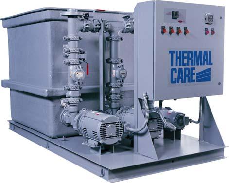
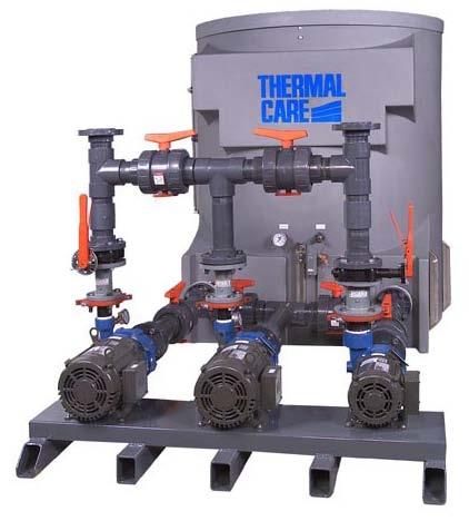
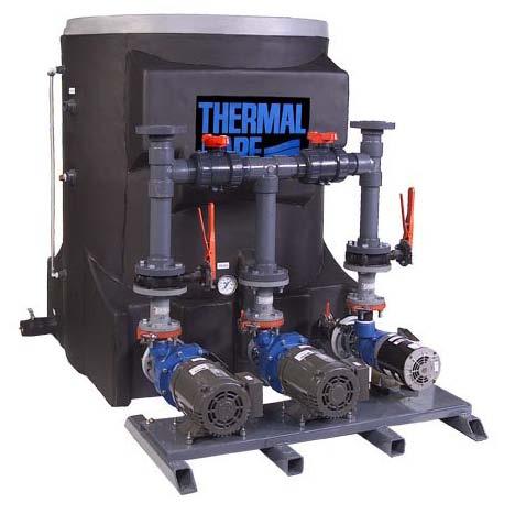
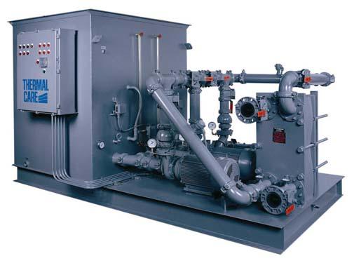
1 PT, PTS & PTP Series Pump/Reservoirs Installation, Operation and Maintenance Manual
2 Table of Contents FOREWORD... 1 INSTALLATION... 1 RECEIVING INSPECTION... 1 RIGGING, HANDLING, AND LOCATING EQUIPMENT... 1 ELECTRICAL POWER... 1 Table 1 - Voltage Utilization Range... 2 PIPING SYSTEM... 2 Table 2 Suggest Pipe Line Sizing... 2 Table 3 - Recommended Glycol Solutions... 3 START-UP... 3 OPERATION... 4 PREVENTIVE MAINTENANCE... 4 ONCE A WEEK... 5 ONCE A MONTH... 5 TROUBLESHOOTING... 6 WARRANTY... 7
3 Foreword The intent of this manual is to serve as a guide for placing your pump/reservoir in service and operating and maintaining it properly. This manual is supplemented as required to accommodate any special items that may have been provided for a specific application. The written information contained in this manual, as well as various drawings, are intended to be general in nature. The schematics included in this manual are typical only. Actual schematics are included in the electrical enclosure of the pump/reservoir and should be referred to for troubleshooting and servicing of the unit. Additional copies of wiring diagrams are available upon request. We strive to maintain an accurate record of all equipment during the course of its useful life. While every effort is made to standardize the design features of these reservoir, the various options may make it necessary to rearrange some of the components; therefore, some of the general drawings in this manual may differ from your specific unit. Specific references to current applicable codes, ordinances, and other local laws pertaining to the use and operation of this equipment are avoided due to their ever-changing nature. There is no substitute for common sense and good operating practices when placing any mechanical equipment into operation. We encourage all personnel to familiarize themselves with this manual's contents. Failure to do so may unnecessarily prolong equipment down time.! CAUTION: The interior of the PT Series steel tanks are lined with a special coating for corrosion protection to provide many years of trouble-free service. Protect your investment by observing the following: Do not weld on or near the tank as hot welding slag or sparks will burn a hole through the tank coating. Do not drill on any tank surface, including the top wall supports. Do not support piping or any other material by attaching it to the tank. Do not drop piping, tools, etc into the tank bottom. Do not place ladders on the tank floor. Use caution when working in or near the tank. Install return water piping just below the operating level of the tank, at the rear of the tank away from the pump suction leg (s). It is recommended that good piping practices are followed and that the information in this manual is adhered to. We cannot be held responsible for liabilities created by substandard piping methods and installation practices external to the chiller. We trust your equipment will have a long and useful life. If you should have any questions, please contact our Customer Service Department specifying the serial number and model number of the unit as indicated on the nameplate. Installation Receiving Inspection Each unit is skid mounted and wrapped with plastic to protect it during shipping. Before accepting delivery, check reservoir for visible damage. If damage is evident, it should be properly documented on the delivery receipt and the plastic wrap should be immediately removed to allow for detailed inspection of the unit. Check for broken gauges, broken lines, damaged controls, or any other major component torn loose from its mounting point. Any sign of damage should be recorded and a claim filed immediately with the shipping company. In order to expedite payment for damages it is important to record and document damage. An excellent way to do this is by taking pictures. Our Customer Service Department will provide assistance with the preparation and filing of your claims, including arranging for an estimate and quotation on repairs. Rigging, Handling, and Locating Equipment The units have a welded frame (except PTP Series Tank which just set on the floor) that has been designed to allow the unit to be positioned with a forklift. Proper rigging methods must be followed to prevent damage to components. Avoid impact loading caused by sudden jerking when lifting or lowering the reservoir. Use pads where abrasive surface contact is anticipated. The unit is designed for indoor use unless specifically designed otherwise. If it is necessary to store the reservoir in an unheated area when not in use, be sure that all water is drained or that an adequate amount of antifreeze is added to prevent freeze-up of the unit. A primary concern when designing your unit was serviceability, therefore, the reservoir should be located in an accessible area. Electrical Power All wiring must comply with local codes and the National Electric Code. Minimum circuit ampacities 1
4 and other unit electrical data are on the unit nameplate in the control panel and on the drawings that are provided in the control panel. Some reservoirs are provided without any controls so this section may not apply to your reservoir. If you did receive a control panel, a specific electrical schematic is shipped with the unit. Measure each leg of the main power supply voltage at the main power source. Voltage must be within the voltage utilization range given in Table 1. Table 1 - Voltage Utilization Range Rated Voltage Utilization Range to to to 633!! WARNING: It is imperative that L1-L2- L3 are connected in the A-B-C phase sequence to prevent equipment damage due to reverse rotation. WARNING: The control panel and safeties are wired such that connecting the appropriate power source to the main terminal block energizes the entire electric circuitry of the chiller. A control transformer has been factory wired to step down the incoming power to the 115-volt control power. Electric power at the main disconnect should be shut off before opening access panels for repair or maintenance. The unit must be properly grounded in compliance with local and national codes. If the measured voltage on any leg is not within the specified range, notify the supplier and correct before operating the unit. Voltage imbalance must not exceed two percent. Excessive voltage imbalance between the phases of a three-phase system can cause motors to overheat and eventually fail. Voltage imbalance is determined using the following calculations: % Imbalance = (V avg V x ) x 100 / V avg V avg = (V 1 + V 2 + V 3 ) / 3 V x = phase with greatest difference from V avg For example, if the three measured voltages were 442, 460, and 454 volts, the average would be: ( ) / 3 = 452 The percentage of imbalance is then: ( ) x 100 / 452 = 2.2 % This exceeds the maximum allowable of 2%. A terminal block is provided for main power connection to the main power source. The main power source should be connected to the terminal block through an appropriate disconnect switch. A separate lug for grounding the unit is also provided in the main control panel. Electrical phase sequence must be checked at installation and prior to start-up. Operation of the system with incorrect electrical phase sequencing can result in mechanical damage to the equipment. The phasing must be checked with a phase sequence meter prior to applying power. The proper sequence should read ABC on the meter. If the meter reads CBA, open the main power disconnect and switch two line leads on the line power terminal blocks (or the unit mounted disconnect). All components requiring electric power are wired in-phase at the factory. Do not interchange any load leads that are from the unit contactors or the motor terminals. 2 Piping System It is very important that the proper sized pipe be used for the supply and return piping for the process equipment and the cooling tower or chiller. See the ASHRAE Handbook or other suitable design guide for proper pipe sizing. We recommend water velocities of between 5 feet/sec and 10 feet/sec (see Table 2 Suggest Pipe Line Sizing). In general, run full size piping out to the process equipment and chiller or cooling tower and then reduce the pipe size to match the connections on the process equipment. One of the most common causes of unsatisfactory reservoir system performance is poorly designed piping. Avoid unnecessarily long lengths of hose or quick disconnect fittings that offer high resistance to water flow. When manifolds are required for water distribution, they should be located as close to the use point as possible. Provide flow-balancing valves at each machine to assure adequate water distribution in the entire system. Table 2 Suggest Pipe Line Sizing Pipe Diamerter Recommended Flow (inches) Range (GPM) ½ ¾ 1 1¼ 1½ 2 2½ For cooling tower systems we recommend tower return lines over 10 feet in length be pitched with a minimum of ¼ inch drop per foot of run. If pipes are to be hung from bar joists; always check the load bearing capacity to insure there is enough strength to support the operating weight of the pipe when filled with water. We also suggest each pipe run be marked with color coded arrows that indicate the direction of flow.
5 Note: All piping must be supported from the building. The reservoir is not designed to support piping. Supporting piping on the reservoir can result in fiberglass fractures that will develop into a leak or a complete loss of the water reservoir structural integrity. If the reservoir is part of a chilled water system, glycol must be added to the water if the system will operate below 45 F. The surface temperature in a chiller evaporator is normally 10 F to 15 F lower than the chilled water temperature. When the desired chilled water temperature is set at 42 F, the heat exchange surface temperature is at the freezing point of water. Icing may begin to cover the tube sheets which reduces the heat transfer rate and may eventually damage the chiller. To prevent this condition, a sufficient amount of antifreeze must be added to the chilled water circuit in order to prevent freeze-ups (see Table 3 - Recommended Glycol Solutions). Note: All chilled water piping systems should be adequately insulated to prevent condensation. Condensation on piping will occur when water vapor in the air comes in contact with the cool surface of the uninsulated chilled water piping and the water vapor changes state to a liquid. The heat that is removed during the change of state is picked up by the chilled water flowing inside the pipe and becomes an additional heat load for the system that will substantially reduce the ability of the chiller to cool the process equipment. Note: For all chilled water systems requiring a glycol mixture, if an automatic make-up system is included, the make-up water must contain the appropriate glycol mixture. Note: If the reservoir will operate with an outdoor air cooled chiller, the water must contain a sufficient glycol percentage to protect it from freezing down to the coldest winter temperatures for the installation. Table 3 - Recommended Glycol Solutions Chilled Water Temperature Percent Glycol By Volume 50 F (10 C) Not required 45 F (7.2 C) 5 % 40 F (4.4 C) 10 % 35 F (1.7 C) 15 % 30 F (-1.1 C) 20 % 25 F (-3.9 C) 25 % 20 F (-6.7 C) 30 % 15 F (-9.4 C) 35 % 10 F (-12.2 C) 35 % 5 F (-15 C) 40 % 0 F (-17.8 C) 40 % Start-Up Due to variables involved with different applications and different installations, minor adjustments may be required during the initial start-up to ensure proper operation. The following start-up procedure should be followed in sequence. If trouble is encountered during start-up, the fault can usually be traced to one of the control or safety devices. This outline can be used as a checklist for the initial start-up and for subsequent start-ups if the chiller is taken out of service for a prolonged period of time. 1. Assure the main power source is connected properly, that it matches the voltage shown on the nameplate of the unit, and that it is within the voltage utilization range given in Table 1. Electrical phase sequence must be checked at installation and prior to start-up. Operation of the equipment with incorrect electrical phase sequencing can result in mechanical damage to the equipment and improper performance. The phasing must be checked with a phase sequence meter prior to applying power. The proper sequence should read ABC on the meter. If the meter reads CBA, open the main power disconnect and switch two line leads on the line power terminal blocks (or the unit mounted disconnect). Do not interchange any load leads that are from the unit contactors or the motor terminals. Once proper power connection and grounding have been confirmed, turn the main power on.! WARNING: It is imperative that L1-L2-L3 are connected in the A-B-C phase sequence to prevent equipment damage due to reverse rotation. 2. Completely drain the reservoir and make sure it is clean and free of any debris. Inspect the water piping to ensure it has been installed correctly. Refer to Installation section for further instructions. 3. Close the drain valve. Fill the reservoir with water (or a water/glycol solution for chilled water reservoirs) to a level just below the overflow connection. For cooling tower reservoirs that include a water makeup valve, this can be automatically accomplished by opening the city water supply valve to the water make-up valve. For chilled water system a proper water/glycol solution should be used to ensure the proper level of freeze protection is provided. Please refer to Table 3 Recommended Glycol Solutions for recommended glycol solutions. Note: If the reservoir includes a make-up valve and the makeup water supply pressure is above 50 PSI, the float make have a hard time shutting off the water. If this is the case, a pressure-reducing valve will be required. 4. Adjust the suction valve of each pump to be fully open (parallel to the suction leg pipe). Adjust the discharge of each pump to be fully closed (perpendicular to discharge pipe). 5. Adjust the valve to each pump pressure gauge to be fully open (parallel to the pilot tube). 6. Switch on the main power disconnect. 3
6 7. Momentarily start each pump individually. Note the pressure reading on the pump discharge pressure gauge. If the pressure reading is lower than design it may be an indication that the pump is running backwards. If the pump is running backwards you can correct rotation by performing the following: a. Stop the pump b. Shut off disconnect c. Switch any two leads of the three-phase power to the pump motor d. Reconnect wiring e. Switch on disconnect f. Start the pump again and check for proper rotation. If pump rotation is correct and the pressure is still too low, contact the Customer Service Department for assistance before proceeding further. Once the proper pump rotation and operation is verified proceed to the next step. If you encounter problems getting the pump(s) to produce the pressure, stop the start-up procedure and contact our Customer Service Department for assistance. Note: Reservoir systems typically control the Cooling Tower Pump (P2) thermostatically. To start the Cooling Tower Pump, turn the Cooling Tower Pump on and lower the set point of the reservoir thermostat until the Cooling Tower Pump energizes. 8. Check to make sure the suction valve is still open (parallel to suction leg) and then open the discharge valve to about the 10% open position (100% open position is parallel to discharge pipe). 9. Run each pump circuit for short periods of time to allow the system to slowly fill. Slowly filling the system will all for the removal of any air that may be in the system piping. Failure to do so can result in excessive water hammer and broken piping connections. Note: Monitor the water level in the reservoir during system pipe filling to ensure the water level always remain above the suction legs of the pumps. Operating a pump without water will cause cavitation and pump seal failure. 10. Once water starts to return to the reservoir from the system return lines, turn the pump on and leave it on. 11. Open the discharge valve slowly until the pump discharge pressure gauge is at the desired pressure. Refer to the pump curves to help in determining the proper pressure associated with the desired flow. 12. Allow the system to operate for about 15 minutes. During this period of time carefully monitor the water level in the reservoir to ensure the pump suction legs remain under water. If a low-level condition occurs, stop the pumps and add fluid to the reservoir. 13. After the system has been operating for 15 minutes, check for leaks, vibration or excessive noise in the pumps or system piping. If there are signs of any of these stop the system and make repairs before proceeding. 14. Before turning off the pumps, measure the amperage on each power lead for each pump (and cooling tower fan motor is applicable). The measured amperage on any lead must not exceed the amperage listed on the pump motor nameplate(s). The unit is now ready to be placed into service. Operation Each reservoir system us custom designed for a particular application and therefore the control and operation of the reservoir system can not be univerally desribed in this manual. The reservoir should have been provided with a suggest piping schematic, wiring diagram and mechanical layout diagram. These drawings are usually shipping inside the control panel of the unit. If the system was ordered without a control panel these drawings would have been shipped with the unit. Please refer to these drawings for specific information about the system design and operation of your particular system. Preventive Maintenance Once the pump/reservoir system has been placed into service, the following maintenance procedures should be adhered to as closely as possible. The importance of a properly established maintenance program can not be over emphasized. Taking the time to follow these simple procedures will result in substantially reduced down time, reduced repair cost, and an extended useful lifetime for the equipment. Any monetary costs associated with implementing these procedures will almost always more than pay for themselves. To help make the preventive maintenance as simple as possible, a checklist should be prepared which lists the recommended service operations and the time at which they are to be performed. With this information, maintenance personnel may be able to correct a potential problem before it causes significant down time. For best results, these readings should be taken with a full heat load from 4
7 process, preferably with similar operating conditions each time. The following is a list of suggested periodic maintenance. Once a Week 1. Check the interior of the reservoir for dirt and debris. 2. Check all pumps in the system for signs of leaks in the pump seal area. Replace pump seal if necessary. 3. Check the pump discharge pressure on the gauges of each pump in the system. Investigate further if the pump discharge pressure starts to stray away from the normal operating pressure. This could be a sign that the pump impeller is worn or damaged. Replace if necessary. 4. Check the coolant level in the reservoir. Replenish if necessary making sure to take proper precautions to maintain the appropriate glycol concentration for chilled water system reservoirs. Repeat items 1 through 4 listed above and continue with the following. Once a Month 5. With the main disconnect shut off and locked out, check the condition of all electrical connections at the contactors, starters and controls. Check for loose or frayed wires and make repairs as necessary. 6. Check the incoming voltage to make sure it is within 10% of the design voltage for the system. 7. Check the amp draws to each leg of all motors in the system and confirm that they are drawing the proper current. 5
8 Troubleshooting Problem Cause Remedy Pump does not produce enough discharge pressure Pump runs rought and makes pinging sound indicating cavitation Pressure gauge defective Pump operating at the end of the operating curve Backwards pump rotation Water level too low in the reservoir Debris in suction line Suction valve partially closed Overload Blocked ventilation Replace pressure gauge Throttle back the discharge valve unit the gauge reads design pressure Check rotation and change any two wired to reverse rotation Fill to proper level Clean suction line of any debris Make sure suction valve is fully open Reduce number of starts per hour or increase motor size Clean external ventilation system Motor runs excessely hot TEFC Motor ODP Motor Ambient temperature over 105 F Unbalanced current draw Check fan Blow out internal ventilation passages Reduce ambient temperatire or provide source of cooler air Balance supply voltage Single-phasing Eliminate single-phasing Pump will not start (hums and heats up) Pump runs noisy under load (excessive electrical noise or chatter under load) Single-phasing Rotor ir bearings locked Single-phasing Motor mount loose Eliminate single-phasing Check motor and replace if needed Be sure proper sized overload relays are in each of the three phases Check motor mount is tight Excessive pump vibration Motor bearing failure Couling loose Replace motor Check coupling is tight and properly aligned (if base-mount pump coupling) 6
User s Manual D-Series Blowers and Exhausters
 User s Manual D-Series Blowers and Exhausters D05-1 ½ HP TEFC 115/230 VOLTS, 1 PH D05-3 ½ HP TEFC 208/230/460 VOLTS, 3 PH D10-1 1 HP TEFC 115/230 VOLTS, 1 PH D10-3 1 HP TEFC 208/230/460 VOLTS, 3 PH D15-1
D-Series Blowers and Exhausters
 Operation and Maintenance Manual D-Series MONOXIVENT - SOURCE CAPTURE SYSTEMS - info@ Oct. - 2015 MONOXVENT BLOWERS AND EXHAUSTERS D05-1 D05-3 D10-1 D10-3 D15-1 D15-3 D20-1 D20-3 D30-1 D30-3 ½ HP TEFC
NECO Pumping Systems
 INSTALLATION OPERATION & MAINTENANCE INSTRUCTIONS For Your NECO Pumping Systems PACKAGED CIRCULATING SYSTEM THIS COMPLETELY ASSEMBLED, TESTED, PACKAGED CIRCULATING SYSTEM IS OF THE HIGHEST QUALITY AND
WELDING FUME EXHAUSTERS & ARMS
 WELDING FUME EXHAUSTERS & ARMS The Ace 75 Series is our flexible and effective line of welding fume exhausters and extraction arms for shops that elect to exhaust their weld fumes outdoors instead of through
Trouble Shooting Guide EWA, 3-phase (D2422)
") Trouble Shooting Guide EWA, 3-phase (D2422) Trouble Shooting Guide Problem Possible Cause Possible Remedy Unit does not start Breaker tripped, no power to unit Loose wire Defective contactor or coil Close
Trouble Shooting Guide EWA, 3-phase (D2422) Trouble Shooting Guide Problem Possible Cause Possible Remedy Unit does not start Breaker tripped, no power to unit Loose wire Defective contactor or coil Close
Installation Operation & Maintenance Manual. Oil-Free (Dry) Rotary Vane Vacuum Pump Systems
 Rotary Vane Vacuum Pump Systems") Installation Operation & Maintenance Manual Oil-Free (Dry) Rotary Vane Vacuum Pump Systems Part No. 9983-0000-S07 / November 2018 OIL-FREE (DRY) ROTARY VANE VACUUM PUMP SYSTEMS TABLE OF CONTENTS CUSTOMER
Installation Operation & Maintenance Manual Oil-Free (Dry) Rotary Vane Vacuum Pump Systems Part No. 9983-0000-S07 / November 2018 OIL-FREE (DRY) ROTARY VANE VACUUM PUMP SYSTEMS TABLE OF CONTENTS CUSTOMER
Installation & Operating Manual
 Installation & Operating Manual 25IPCC-M 7/08 Edition PC Series C E N T R I F U G A L Congratulations On Your Choice In Purchasing This Webtrol Pump Its Quality is unsurpassed in material and workmanship
TC Series Cooling Systems
 TC Series Cooling Systems Table of Contents Table of Contents...1 List of Figures...1 Safety...2 Introduction...2 General Specifications...2 Types of Coolant...2 Routine Maintenance...2 Surge Tank Coolant
PHANTOM (PH10 and PH12) COMMERCIAL AND INDUSTRIAL SERIES
 COMMERCIAL AND INDUSTRIAL SERIES") Document No: ICM-IOM Date: 0411 PHANTOM (PH10 and PH12) COMMERCIAL AND INDUSTRIAL SERIES Installation, Operation and Maintenance Manual Please read and save these instructions. Read carefully before attempting
Document No: ICM-IOM Date: 0411 PHANTOM (PH10 and PH12) COMMERCIAL AND INDUSTRIAL SERIES Installation, Operation and Maintenance Manual Please read and save these instructions. Read carefully before attempting
USER S MANUAL FOR F & Q. Submersible Sewage Pumps
 USER S MANUAL FOR F & Q Submersible Sewage Pumps 100WQ Series The F&Q pumps are carefully inspected and tested to ensure operating performance and safety. However, failure to follow the instructions and
SEASONAL MAINTENANCE CHECKLISTS Johnson Controls
 SPRING CHECK LIST ABSORPTION CHILLERS Check starter and control panel. Leak test. Check hand valve diaphragms and replace as required. Check operation of purge unit. Change oil in the purge pump. Lubricate
A. Products shall be designed, manufactured, tested, and installed in compliance with the following standards:
 SECTION 26 29 13 ENCLOSED MOTOR CONTROLLERS PART 1 - GENERAL 1.1 RELATED DOCUMENTS: A. The Conditions of the Contract and applicable requirements of Divisions 0 and 1 and Section 26 00 01, Electrical General
PreSoak System (NonFoaming) DU PS1-HP DU PS6-HP
 DU PS1-HP DU PS6-HP") PreSoak System (NonFoaming) DU PS1-HP DU PS6-HP Serial Number: Owner s Manual #0786 040810 Installation Date: Please read and u n d e r s t a n d t h i s manual. Store in safe location for future reference.
PreSoak System (NonFoaming) DU PS1-HP DU PS6-HP Serial Number: Owner s Manual #0786 040810 Installation Date: Please read and u n d e r s t a n d t h i s manual. Store in safe location for future reference.
WINDGUARD BELT DRIVE (BD) INDUSTRIAL SERIES
 INDUSTRIAL SERIES") Document No: BD-IOM Date: 01/13/16 WINDGUARD BELT DRIVE (BD) INDUSTRIAL SERIES Installation, Operation and Maintenance Manual Please read and save these instructions. Read carefully before attempting to
Document No: BD-IOM Date: 01/13/16 WINDGUARD BELT DRIVE (BD) INDUSTRIAL SERIES Installation, Operation and Maintenance Manual Please read and save these instructions. Read carefully before attempting to
High Pressure Pump Units featuring CAT PUMPS DUPM550 & DUPM570
 High Pressure Pump Units featuring CAT PUMPS DUPM550 & DUPM570 Serial Number: Owner s Manual #0789 122315 Installation Date: Please read and understand this manual. Store in safe location for future reference.
SELF PRIMING CHEMICAL SERVICE PUMPS
 SELF PRIMING CHEMICAL SERVICE PUMPS INSTALLATION AND OPERATING INSTRUCTIONS This Manual covers: SELF PRIMING MODEL RANGE J50ECX TO J250ECX STAINLESS STEEL*, and NON METALLIC SEAL PUMP MODEL: SERIAL NO:
Presoak & Tire/Engine Cleaner Systems (Air Pump) DU TC_A & DU PS_A
 DU TC_A & DU PS_A") Presoak & Tire/Engine Cleaner Systems (Air Pump) DU TC_A & DU PS_A Owner s Manual #0795 Customer Number: Model Number: Serial Number: Installation Date: IMPORTANT Please read and u n d e r s t a n d t
Presoak & Tire/Engine Cleaner Systems (Air Pump) DU TC_A & DU PS_A Owner s Manual #0795 Customer Number: Model Number: Serial Number: Installation Date: IMPORTANT Please read and u n d e r s t a n d t
Wash Prep Systems featuring CAT PUMPS DUPM623 DUPM820 / DUPM820-TS DUPM820D / DUPM820D-TS DUPM1010. Owner s Manual #
 Wash Prep Systems featuring CAT PUMPS DUPM623 DUPM820 / DUPM820-TS DUPM820D / DUPM820D-TS DUPM1010 Serial Number: Owner s Manual #0779 072415 Installation Date: Please read and understand this manual.
INSTALLATION, OPERATION AND MAINTENANCE MANUAL WALL EXHAUST FANS BELT & DIRECT DRIVE XB, HV, HVA, ADD, DDS, DDP
 INSTALLATION, OPERATION AND MAINTENANCE MANUAL WALL EXHAUST FANS BELT & DIRECT DRIVE XB, HV, HVA, ADD, DDS, DDP The purpose of this manual is to aid in the proper installation and operation of the fans.
SUNC1200 / ITEM #40882 SUBMERSIBLE UTILITY PUMP OPERATIONS MANUAL
 SUNC1200 / ITEM #40882 SUBMERSIBLE UTILITY PUMP OPERATIONS MANUAL WWW.SUNRUNNERPOOL.COM Performance Model HP GPH of Water @ Total Feet Of Lift 0 ft. 5 ft. 10 ft. 15 ft. 20 ft. 25 ft. Max. Lift SUNC1200
WIND STOPPING 14 (WMI) AND WIND STOPPING 16 (WMH) INDUSTRIAL SERIES
 AND WIND STOPPING 16 (WMH) INDUSTRIAL SERIES") Document No: W-IOM Date: 01/13/16 WIND STOPPING 14 (WMI) AND WIND STOPPING 16 (WMH) INDUSTRIAL SERIES Installation, Operation and Maintenance Manual Please read and save these instructions. Read carefully
Document No: W-IOM Date: 01/13/16 WIND STOPPING 14 (WMI) AND WIND STOPPING 16 (WMH) INDUSTRIAL SERIES Installation, Operation and Maintenance Manual Please read and save these instructions. Read carefully
Enclosed Electric Rotary Screw Compressor Installation Guide
 Enclosed Electric Rotary Screw Compressor Installation Guide Air compressors should only be installed trained installation personnel call 800-531-9656 to find a local trained. Warning: Read all installation
Installation & Operating Manual
 Installation & Operating Manual Centrifugal Pump SPC75 & SPC150 Self-Priming / Stainless Steel Congratulations On Your Choice In Purchasing This Webtrol Pump Its Quality is unsurpassed in material and
Centrifugal Pumps (Part Nos. PS2SS PS73SS) PS2SS
 PS2SS") Centrifugal Pumps (Part Nos. PS2SS PS73SS) PS2SS Part No. Serial Number Date Purchased Table of Contents Page Safety Messages...2 Pump Curves...2 Pump End Assembly...3 Disassembly...3 Installation...4
Centrifugal Pumps (Part Nos. PS2SS PS73SS) PS2SS Part No. Serial Number Date Purchased Table of Contents Page Safety Messages...2 Pump Curves...2 Pump End Assembly...3 Disassembly...3 Installation...4
INSTALLATION, OPERATION AND MAINTENANCE MANUAL WALL EXHAUST FANS BELT DRIVE XBL FANS
 INSTALLATION, OPERATION AND MAINTENANCE MANUAL WALL EXHAUST FANS BELT DRIVE XBL FANS The purpose of this manual is to aid in the proper installation and operation of the fans. These instructions are intended
USER S MANUAL FOR F & Q. Submersible Sewage Pumps
 USER S MANUAL FOR F & Q Submersible Sewage Pumps 50WQ Series The F&Q pumps are carefully inspected and tested to ensure operating performance and safety. However, failure to follow the instructions and
CALTRAP INSTALLATION AND OPERATIONS MANUAL
 INSTALLATION AND OPERATIONS MANUAL NOTE Please read this entire installation and operations manual before energizing the. Safety Considerations: Installing and servicing capacitor equipment can be hazardous.
BOILER FEED SYSTEM OPERATION AND MAINTENANCE MANUAL
 BOILER FEED SYSTEM OPERATION AND MAINTENANCE MANUAL IMPORTANT These instructions are intended as a guide for the Installing Contractor and as a reference for the Operator, Owner and Serviceman. RETAIN
Standard Service / Installation / Operation Manual Type W & P Water / Glycol Heat Transfer Coils
 Standard Service / Installation / Operation Manual Type W & P Water / Glycol Heat Transfer Coils Please consult your local representative or the factory for warranty issues. July 2017 DRS Marlo Coil Customer
TYPE MA General Purpose Multi-motor Converter TYPE MA-A Type MA Converter with automatic control TYPE MA-R Type MA Converter with switch and fuses
 INSTALLATION MANUAL TYPE MA General Purpose Multi-motor Converter TYPE MA-A Type MA Converter with automatic control TYPE MA-R Type MA Converter with switch and fuses CONTENTS I. BEFORE YOU START... 2
PHANTOM (PH10 and PH12) COMMERCIAL AND INDUSTRIAL SERIES
 COMMERCIAL AND INDUSTRIAL SERIES") Document No: ICM-IOM Date: 1015 PHANTOM (PH10 and PH12) COMMERCIAL AND INDUSTRIAL SERIES Installation, Operation and Maintenance Manual Please read and save these instructions. Read carefully before attempting
Document No: ICM-IOM Date: 1015 PHANTOM (PH10 and PH12) COMMERCIAL AND INDUSTRIAL SERIES Installation, Operation and Maintenance Manual Please read and save these instructions. Read carefully before attempting
Installation Operation Maintenance. LSSN Butterfly Valve AGA Approved 50MM - 150MM. QAD#IM6055.REVA
 LSSN Butterfly Valve Installation Operation Maintenance Licence Number: 5326 www.challengervalves.com.au 1 Index 1. INTRODUCTION 1.1 Design Features 3 1.2 Flange and Pipe Compatibility 4 1.3 Operating
Matala. VersiFlow Series. Instruction and Maintenance Manual
 VersiFlow Series High Flow Multi-Purpose "Versatile " Pump V-3200 1/5HP 150W / Discharge 2 V-3900 1/3HP 250W / Discharge 2 V-4700 1/2HP 400W / Discharge 2 V-5600 1HP 750W / Discharge 2 Instruction and
Operators Manual. Recirculating Chiller /06/08
 Operators Manual Recirculating Chiller 110-197 11/06/08 Table of Contents Section 1. General Information 1.1 Warranty 1.2 Unpacking 1.3 Package Contents 1.4 Description of the Recirculating Chiller 1.5
XCITE Owner s Manual. Reso-not TM Damping System XCITE 1502C HYDRAULIC POWER SUPPLY
 Reso-not TM Damping System XCITE Owner s Manual 1502C HYDRAULIC POWER SUPPLY Xcite Systems Corporation 675 Cincinnati RDS Batavia - 1 Pike Cincinnati, Ohio 45245 Tel: (239) 980-9093 Fax: (239) 985-0074
NSGV PT-1000 PORTABLE WELDING STATION I, O & M MANUAL
 APPLICATION OF DUST CONTROL EQUIPMENT: CAUTION - Warning Improper operation of dust control system may contribute to conditions in the work area or facility that could result in severe personal injury
VAGABOND S HANDBOOK TRANSMISSION
 03/24/07 TRANSMISSION Transmission won t engage into Gear This is caused usually by too low a Voltage to get into the ECM. This unit requires a minimum of 9VDC in order to operate at all. Almost all erratic
KP-C Series. Close Coupled End Suction Centrifugal Pumps. Installation, Operation and Maintenance
 KP-C Series Close Coupled End Suction Centrifugal Pumps Installation, Operation and Maintenance PUMP MODEL NOMENCLATURE KP - 8 x 6 x 16 - E C - AI - BCM Pump Series Suction Pipe Size (in) Discharge Pipe
Pump Installation and Service Manual HRS Hydromatic Retractable System
 Pump Installation and Service Manual HRS Hydromatic Retractable System NOTE! To the installer: Please make sure you provide this manual to the owner of the pumping equipment or to the responsible party
SOLAR LIGHTING CONTROLLER SUNLIGHT MODELS INCLUDED IN THIS MANUAL SL-10 SL-10-24V SL-20 SL-20-24V
 SOLAR LIGHTING CONTROLLER OPERATOR S MANUAL SUNLIGHT MODELS INCLUDED IN THIS MANUAL SL-10 SL-10-24V SL-20 SL-20-24V 10A / 12V 10A / 24V 20A / 12V 20A / 24V 1098 Washington Crossing Road Washington Crossing,
Owner's/Installation Manual
 Owner's/Installation Manual Power Management Module (PMM) and Starter Kit NOTE: The starter kit must be purchased and installed prior to individual PMM usage. Model Numbers: 00686-0 PMM 00699-0 PMM WITH
INSTALLATION AND OPERATION INSTRUCTIONS 4400QC SERIES POWER PAKS
 INSTALLATION AND OPERATION INSTRUCTIONS 4400QC SERIES POWER PAKS MODELS 4400QC Series 4404QC 4410QC 4414QC 4420QC C US IMPORTANT INFORMATION To register your product, visit our web site at www. perlick.com.
Jet Fans. Instruction Manual READ AND SAVE THESE INSTRUCTIONS WARRANTY
 Jet Fans Instruction Manual READ AND SAVE THESE INSTRUCTIONS WARRANTY All Leader Fan products are guaranteed to be free from defects of workmanship or material and to function satisfactorily when properly
INSTALLATION, OPERATION, AND MAINTENANCE MANUAL RBK FRP FAN
 Bulletin 62-January-20-09 ROOF UPBLAST & SIDEWALL CENTRIFUGAL FIBERGLASS EXHAUST FAN INSTALLATION, OPERATION, AND MAINTENANCE MANUAL RBK FRP FAN The M.K. Plastics catalog on the above corrosion resistant
PAGE 1. TES Operation & Testing Guidelines: Tes Trouble shooting
 PAGE 1 This document outlines questions to ask and components to check during TES troubleshooting. More detailed troubleshooting procedures are available in the TES Troubleshooting Guide. 1. Flow Light
Pressure Makeup Jockey Pump Controller
 Hubbell Industrial Controls, Inc. A subsidiary of Hubbell Incorporated 4301 Cheyenne Dr. Archdale, NC 27263 Telephone (336) 434-2800 FAX (336) 434-2803 Instruction Manual Pressure Makeup Jockey Pump Controller
of Fire Pump Assemblies
 A.1.0 A.1.1 A.2.0 A.2.1 A.2.2 A.2.3 A.2.4 A.2.5 A.2.6 A.3.0 A.3.1 A.4.0 A.4.1 Report of Inspection, Testing & Maintenance System in service before conducting tasks Pertinent parties notified before conducting
Professional Séries. Professional Séries. Model T03828 SUBMERSIBLE SUMP DUPLEX SYSTEM SUBMERSIBLE SUMP DUPLEX SYSTEM. 1/3HP 2400 GPH Head of 20 (6 m)
") Model T0828 Primary pump 1/HP 200 GPH Head of 20 (6 m) SUBMERSIBLE SUMP DUPLEX SYSTEM Professional Séries Discharge: 1 1/2 ABS DWV pipe Electric cable: 9 piggyback type Oil cooled Cast iron construction
Model T0828 Primary pump 1/HP 200 GPH Head of 20 (6 m) SUBMERSIBLE SUMP DUPLEX SYSTEM Professional Séries Discharge: 1 1/2 ABS DWV pipe Electric cable: 9 piggyback type Oil cooled Cast iron construction
VADA - V60-J PRODUCT OVERVIEW CONSTRUCTION MOTOR USAGE LIMITATIONS WARRANTY
 PRODUCT OVERVIEW The VADA series of self priming jet pumps combine the functional benefits of centrifugal pumps and the practical and qualitative benefits of self-priming pumps. The Venturi system the
SUPER PUMP OUT SYSTEM
 Congratulations on your purchase of the SUPER PUMP OUT SYSTEM. This instruction/parts manual is a guide for operating and servicing your BLUELINE SUPER PUMP OUT SYSTEM. Proper operation and service are
4" ENVIRONMENTAL E-SERIES PUMPS OWNER'S MANUAL. DANGER warns about hazards that will cause. WARNING warns about hazards that can cause
 4" ENVIRONMENTAL E-SERIES PUMPS OWNER'S MANUAL BEFORE INSTALLING PUMP, BE SURE TO READ THIS OWNER S MANUAL CAREFULLY. CAUTION Fill pump with water before starting or pump will be damaged. The motor on
TITAN FLOW CONTROL, INC.
 PREFACE: This manual contains information concerning the installation, operation, and maintenance of Titan Flow Control (Titan FCI) Wafer Style, Dual Plate Check Valves. To ensure efficient and safe operation
INSTALLATION, OPERATION & MAINTENANCE MANUAL AXIAL UPBLAST FANS RTA, RWTA, RHTA, RB, RD, RTA SH
 INSTALLATION INSTALLATION, OPERATION & MAINTENANCE MANUAL AXIAL UPBLAST FANS RTA, RWTA, RHTA, RB, RD, RTA SH The purpose of this manual is to aid in the proper installation and operation of the fans. These
SeasonPak Packaged Air-Cooled Water Chiller
 Installation Manual IM 676 Group: Chiller Part Number: 594920Y Date: July 1996 Supersedes: None SeasonPak Packaged Air-Cooled Water Chiller Models ALR 032E Through 185E 1996 McQuay International Table
ESE Series Cast Iron Sewage Pumps
 Owner s Manual ESE Series Cast Iron Sewage Pumps TABLE OF CONTENTS General Safety.................... 2 Specifications..................... 3 Installation.................... 4 & 5 Troubleshooting...................
Manual Transfer Switch
 Manual Transfer Switch Instruction Manual 30 1200 Amp 2, 3 & 4 Pole Page 1 WARNING Before Installation READ THIS MANUAL carefully to learn how to properly install, operate and maintain this unit. Personal
ST Charger. Industrial Battery Charger
 ST Charger Industrial Battery Charger Installation and Operation Manual ST_13 Table of Contents Pg# 1.0 INSTALLATION 1 1.1 Receiving 1 1.2 Location 1 1.3 Line Voltage 1 1.4 A.C. Service Requirements 2
Armstrong Double Duty 6 Steam Trap/Pump Combination Installation and Maintenance
 Armstrong Double Duty 6 Steam Trap/Pump Combination Installation and Maintenance 119 Overview Warning: This bulletin should be used by experienced personnel as a guide to the installation and maintenance
Installation, Operating, Maintenance and Safety Instructions for CW332 Pressurised water system for boats 24 volt d.c.
 24V DC-CW332 DOC531/11 Installation, Operating, Maintenance and Safety Instructions for CW332 Pressurised water system for boats 24 volt d.c. To obtain the best performance from your Pressurised water
Copeland Screw Compressors Semi-Hermetic Compact Operating Instructions
 Copeland Screw Compressors Semi-Hermetic Compact Operating Instructions SCH2 & SCA2 High Temperature Compressors 35-240 Horsepower 1. Introduction This series of semi-hermetic compact screw compressors
Positive Displacement Pump
 www.conairgroup.com U S E R G U I D E UGC028-1105 Positive Displacement Pump Models PD 3. 5, 7.5, 10, 15 and 25 Corporate Office: 724.584.5500 l Instant Access 24/7 (Parts and Service): 800.458.1960 l
Aqua Ultraviolet Sunami Series Pumps 1/3HP, 3/4HP, 3HP, 4HP, 5HP
 TM 42371 Avenida Alvarado Temecula, CA 92590 TOLL FREE (800) 454-2725 TEL (951) 296-3480 FAX (951) 296-3490 www.aquauv.com Aqua Ultraviolet Sunami Series Pumps 1/3HP, 3/4HP, 3HP, 4HP, 5HP Sunami Warranty
BOILER PM & INSPECTION
 BOILER PM & INSPECTION Record inspection log for Gaming Commission and Safety Department. The following listed maintenance items are not intended to be a complete list. Follow any additional maintenance
Water Jetter Units DU JT50 / DU JT100
 Water Jetter Units DU JT50 / DU JT100 Serial Number: Owner s Manual #0818 102011 Installation Date: IMPORTANT Please read and u n d e r s t a n d t h i s manual. Store in safe location for future reference.
QUICK START GUIDE OWNER S MANUAL AL50 SERIES SAND FILTRATION TECHNOLOGY PLEASE CALL DO NOT RETURN TO STORE
 QUICK START GUIDE OWNER S MANUAL SAFETY, INSTALLATION, OPERATION & PARTS AL50 SERIES SAND FILTRATION TECHNOLOGY PLEASE CALL 877-278-2797 DO NOT RETURN TO STORE! WARNING This equipment must be installed
SECTION 3 BASIC AUTOMATIC CONTROLS UNIT 15 Troubleshooting Basic Controls
 SECTION 3 BASIC AUTOMATIC CONTROLS UNIT 15 Troubleshooting Basic Controls UNIT OBJECTIVES After studying this unit, the reader should be able to Describe and identify power- and non-power-consuming Describe
DuraMAC LIGHT COMMERCIAL & IRRIGATION WATER PRESSURE BOOSTER SYSTEM INSTALLATION INSTRUCTIONS
 DuraMAC LIGHT COMMERCIAL & IRRIGATION WATER PRESSURE BOOSTER SYSTEM INSTALLATION INSTRUCTIONS The DuraMAC TM Water Pressure Booster System is the first booster pump of its kind to be designed for virtually
SECOND GENERATION Use this guide with unit serial number prefix beginning with BWF using Terra Power separator.
 Technical Information and Diagnostic Guide for SECOND GENERATION Use this guide with unit serial number prefix beginning with BWF using Terra Power separator. This guide will assist you in becoming more
INSTALLATION AND SERVICE INSTRUCTIONS AND REPAIR PARTS LIST FOR MODELS K4RP & K4VP SUBMERSIBLE SOLIDS-HANDLING SEWAGE PUMPS
 471 US Hwy 250 East, Ashland, Ohio 44805 PH: 419-207-9400 FX: 419-207-8031 INSTALLATION AND SERVICE INSTRUCTIONS AND REPAIR PARTS LIST FOR MODELS K4RP & K4VP SUBMERSIBLE SOLIDS-HANDLING SEWAGE PUMPS 10/2014
PATTERSON PUMP COMPANY
 PATTERSON PUMP COMPANY A Gorman Rupp Company JOCKEY PUMP CONTROLLERS UL508 LISTED ETL LISTED FEB 013 Patterson Jockey Pump controllers are built to NEMA industrial standards and are UL508 listed and ETL
Installation and Operating Manual
 Installation and Operating Manual L-Series Vacuum Pumps Models L/H400C - L/H630C INSTALLATION & OPERATING MANUAL L/H-SERIES SINGLE STAGE ROTARY VANE VACUUM PUMPS L/H400C-L/H630C Please read the manual
Matrix APAX. 380V-415V 50Hz TECHNICAL REFERENCE MANUAL
 Matrix APAX 380V-415V 50Hz TECHNICAL REFERENCE MANUAL WARNING High Voltage! Only a qualified electrician can carry out the electrical installation of this filter. Quick Reference ❶ Performance Data Pages
Cylindrical Silencers
 Cylindrical Silencers A200 Series and 300 Series Installation and Operation Manual Rev. B (c) Copyright 2012, GT Exhaust, Inc. All Rights Reserved Published: April 30, 2012 NOTICE The instructions herein
Operation Guide. Operation Guide. Winnebago Hydraulic Leveling Systems by Kwikee. Introduction. Table of Content WARNINGS
 Operation Guide 05/07 Kwikee #1422192 Rev. 0F Table of Content Page Introduction 1 Safety Information 1 Operation 2 Control Panel 3 Manual Leveling 3 Automatic Leveling 3 Remote Operation 4 Stabilizing
END SUCTION CENTRIFUGAL PUMPS
 OWNERS GUIDE TO INSTALLATION AND OPERATION FW000 009 Supersedes 07 END SUCTION CENTRIFUGAL PUMPS READ THESE INSTRUCTIONS CAREFULLY Read these installation instructions in detail before installing your
Portable Oil Free Silent Series Compressor Operating Instructions
 Portable Oil Free Silent Series Compressor Operating Instructions NOTICE Carefully read this instruction manual before attempting to operate this compressor. MODEL # SERIAL # 1-800-551-2406 www.eaglecompressor.com
ACHL Series Pump. Operation and Maintenance Manual Air Driven, Hand Operated High Pressure Liquid Pump
 ACHL Series Pump Operation and Maintenance Manual Air Driven, Hand Operated High Pressure Liquid Pump Catalog: 02-9245ME February 2013 Model # Serial # Drawing # Order # Mfg. Date Table of Contents page
Direct Gas-Fired Heating
 Direct Gas-Fired Heating Model DG 800 to 15,000 cfm Up to 1,600,000 BTU/hr Optional Evaporative Cooling January 2005 PRODUCT FEATURES Model DG Direct Gas-Fired Make-Up Air Unit The Greenheck model DG is
Farval. Dualine Installation System Start-Up. Bulletin DL300 BIJUR DELIMON INTERNATIONAL
 Farval Dualine Installation System Start-Up Bulletin DL300 BIJUR DELIMON INTERNATIONAL 2685 Airport Road Kinston, NC 28504 Tel. 800-227-1063 Fax: 252-527-9232 website: www.bijurdelimon.com DC1-1 SECTION
Series Base mounted pump. Installation and operating instructions
 Series 4030 Installation and File No: 40.80 Date: june 25, 2015 Supersedes: 40.80 Date: october 10, 2009 contents General 4 Inspection 4 Installation - Series 4030 base mounted Pump 4 1.0 Location 4 2.0
MODEL SCA Installation and Operation Manual Important:
 MODEL SCA Installation and Operation Manual Important: This manual contains specific cautionary statements relative to worker safety. Read this manual thoroughly and follow as directed. It is impossible
Installation, Operation, and Maintenance Manual Outdoor Glycol Feed System JWOP /055/100
 Installation, Operation, and Maintenance Manual Outdoor Glycol Feed System JWOP-53-030/055/100 Rev. 1 3/21/11 K.G. Type - John Wood #JWOP-53-030/055/100, Outdoor Glycol Feed System Capacity 30/55/100 Gallons
A. This Section includes ac, enclosed controllers rated 600 V and less, of the following types:
 SECTION 262913 600 VOLT ENCLOSED CONTROLLERS PART 1 - GENERAL 1.1 RELATED DOCUMENTS A. Drawings and general provisions of the Contract, including General and Supplementary Conditions and Division 0 Specification
BR62 Battery Rack Installation, Operation, & Maintenance Manual
 BR62 Battery Rack Installation, Operation, & Maintenance Manual 8/28/2012 2 755-00046 R02 Copyright 2012 C&C Power, Inc. All rights reserved. C&C Power, Inc. 395 Mission Street Carol Stream, IL 60188 www.ccpower.com
Dual-Lite Trident TRF 40 Wide Battery Cabinet 20-40kVA Systems USER MANUAL
 Dual-Lite Trident TRF 40 Wide Battery Cabinet 20-40kVA Systems USER MANUAL 755-00020-DL 5/17/2017 2 755-00020-OEM R01 TABLE OF CONTENTS 1. Important Information About This Manual... 4 1.1 Manual Symbols...
RAIN BIRD - AQUAGATOR AQUAGATOR INSTALLATION & TROUBLESHOOTING MANUAL
 AQUAGATOR INSTALLATION & TROUBLESHOOTING MANUAL Cozz GT27069-A Revised July 2002 P/N 632360 AQUAGATOR TABLE of CONTENTS DESCRIPTION PAGE INTRODUCTION....... 1 SECTION 1 - PRE-INSTALLATION REQUIREMENTS.
The Da-Lite Difference.
 The Da-Lite Difference. Instruction Book for Large Advantage Electrol DA-LITE SCREEN COMPANY, INC. 3100 North Detroit Street Post Office Box 137 Warsaw, Indiana 46581-0137 Phone: 574-267-8101 800-622-3737
Electric Reciprocating Compressor. Installation Guide
 Electric Reciprocating Compressor Installation Guide Air compressors should only be installed trained installation personnel call 800-531-9656 to find a local trained. Warning: Read all installation steps,
PENTEK XE-6. OWNER S MANUAL 6 Submersible Motors 293 WRIGHT STREET, DELAVAN, WI PH: PENTEK
 OWNER S MANUAL 6 Submersible Motors PENTEK XE-6 232852 DRINKING WATER SYSTEM COMPONENT ANSI/NSF 61-G 3RZE 293 WRIGHT STREET, DELAVAN, WI 53115 WWW.PUMPS.COM PH: 1-866-9 PENTEK 2015 Pentair Ltd. All Rights
Air Curtain. Installation, Operating and Maintenance Instructions
 Installation, Operating and Maintenance Instructions Save this manual for future reference. Air Curtain Model Numbers: ES026, ES036, ES042, ES048, ES060, ES072 READ THIS OWNER S MANUAL CAREFULLY BEFORE
Technical Information and Diagnostic Guide
 Technical Information and Diagnostic Guide This guide will assist you in becoming more familiar with the working components of the NITE System and the proper steps and procedures to completely diagnose
G76x Direct Spark Ignition Controls
 Installation Sheets Manual 121 Gas Combustion Combination Controls and Systems Section G Technical Bulletin G76x Issue Date 0400 G76x Direct Spark Ignition Controls Figure 1: G76x Direct Spark Ignition
START-UP CHECKLIST. Date: Job Name: Customer Name: Address: City: State: Zip: Model Number: Serial Number: Qualified Start-up Technician:
 START-UP INSTRUCTION OPTIMUM 36000 To 72000 BTU S PACKAGE UNITS 3 To 6 Ton START-UP CHECKLIST Date: Job Name: Customer Name: Address: City: State: Zip: Model Number: Serial Number: Qualified Start-up Technician:
Installation Operation & Maintenance Manual. High Vacuum Lubricated Rotary Vane Pumps
 Installation Operation & Maintenance Manual High Vacuum Lubricated Rotary Vane Pumps Part No. 9983-0000-P07 / November 2018 HIGH VACUUM LUBRICATED ROTARY VANE PUMPS TABLE OF CONTENTS CUSTOMER SERVICE 5
Val-Matic Air / Oil Hydraulic Panel Pump Control System. Operation, Maintenance and Installation Manual
 Manual No. 5AOP-OM1-2 Val-Matic Air / Oil Hydraulic Panel Pump Control System Operation, Maintenance and Installation Manual INTRODUCTION... 1 RECEIVING AND STORAGE... 1 DESCRIPTION OF OPERATION... 1 INSTALLATION...
CENTRIFUGAL CHILLER. Lubrication System Pull oil sample for spectroscopic analysis.
 CENTRIFUGAL CHILLER Annual Inspection Refrigerant Circuit Check and record refrigerant level Inspect for leak results Calculate refrigerant lass and report to the customer. Repair minor leaks as required
READ AND SAVE THESE INSTRUCTIONS
 READ AND SAVE THESE INSTRUCTIONS Part #469003 Model Vektor -H Installation Operation and Maintenance Manual for Vektor-H Laboratory Exhaust System Receiving Greenheck model Vektor-H fans are thoroughly
POWER FACTOR CORRECTION MOTOR LOAD (ML) FIXED CAPACITOR
 FIXED CAPACITOR") User s Manual for The POWER FACTOR CORRECTION MOTOR LOAD (ML) FIXED CAPACITOR 301 Gaddis Boulevard Dayton, Ohio 45403 U.S. Toll Free 866-261-1191 (937) 253-1191 Fax: (937) 253-1723 Web site: www.stacoenergy.com
User s Manual for The POWER FACTOR CORRECTION MOTOR LOAD (ML) FIXED CAPACITOR 301 Gaddis Boulevard Dayton, Ohio 45403 U.S. Toll Free 866-261-1191 (937) 253-1191 Fax: (937) 253-1723 Web site: www.stacoenergy.com
Installation and operating instructions. Series 4312 and 4392 Vertical In-Line twin pumps
 Installation and operating instructions Series 4312 and 4392 Vertical In-Line twin pumps File No: 43t.86 Date: july 16, 2012 Supersedes: 43.86 Date: july 16, 2010 contents 1.0 Introduction 4 1.1 Warnings
University of Houston Master Construction Specifications Insert Project Name
 SECTION 23 30 00 - HVAC PUMPS PART 1 - GENERAL 1.1 RELATED DOCUMENTS: A. The Conditions of the Contract and applicable requirements of Division 1, "General Requirements", and Section 23 01 00, "Mechanical