Dental Dry Suction. Installation/User Guide
|
|
|
- Bartholomew Miles
- 5 years ago
- Views:
Transcription
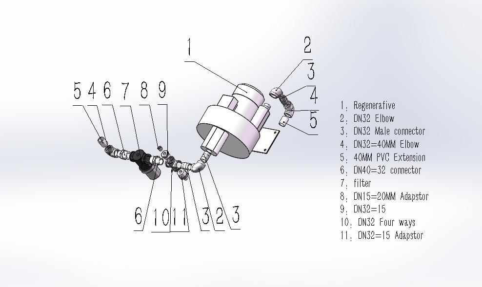
1 Dental Dry Suction System Installation/User Guide Operation & Maintenance Manual Registered Trademark/ EcoPowerVac Trademark of Omxie Corp. Copyright All Rights Reserved. 1 P a g e
2 Dental Dry Suction System User Guide 2017, Omxie Corp. We reserve the right to make any alterations which may be due to any technical improvements Printed in the USA IMPORTANT SAFETY INSTRUCTIONS Dear Customer: Congratulations on the purchase of your new EcoPowerVac Dry Dental Suction System from Omxie Corp.. This system s intended purpose is for dental suction applications. It is to be used in accordance with UL and NFPA 99C standards, along with all applicable codes. The system utilizes a dry vacuum regenerative blower that produces high air flow when connected to the dental operatory lines. A vacuum electronic sensor and variable frequency loader are also included to maximize the system s efficiency by holding a constant vacuum level. This manual provides installation, operation and preventative maintenance guidelines that should be followed to ensure correct/reliable performance of this system. WARNING: PLEASE READ THIS MANUAL COMPLETELY BEFORE INSTALLING AND USING THIS PRODUCT. SAVE THIS MAN- UAL FOR FUTURE REFERENCE AND KEEP IN THE VICINITY OF THE PRODUCT. 2 P a g e
3 Table of Contents Related Safety Instructions and Regulations... 4 EcoPowerVac Outlines... 4 Unpack... 4 Installation and safety... 5 Site Requirements... 5 Electrical Requirements... 7 Plumbing... 8 Installation - Below Grade... 9 Installation - Above Grade... 9 Installation-Electrical Connections Installations-Checks and Tests Operation Preventive Maintenance Specifications Troubleshooting Chart Options & Accessories Warranty Installation Check list P a g e
4 RELATED SAFETY INSTRUCTIONS AND REGULATORYS To provide suction during general dental examinations and procedures conducted by qualified dental professionals. EcoPowerVac systems meet or exceed the most current and highest safety standards, which are: CSA C M90 (2005) UL classified revision 2006/04/26 - Classification: Class I, permanently fixed MAINS operated equipment NFPA 99C level 3 gas system requirements compliance revision 2005 To ensure the safety potential of this equipment is achieved, please: Make sure your equipment is installed according to the instructions provided in this manual and make sure the installation checklist is completed prior to starting the equipment. Equipment is not suitable for use in the presence of a flammable anesthetic mixture containing air/oxygen or nitrous oxide. DO NOT OPERATE THE EQUIPMENT IF THESE CONDITIONS EXIST. Protection against electrical shock: Provide proper grounding per NFPA 70 (NEC 2008). Do not become a current path for the equipment to ground through your body. Transportation/Storage Conditions: Temperature range C to 50 C / -20 F to 122 F Relative Humidity 95% (non-condensing) Barometric pressure minimum of 372 mm Hg (.49 atm). Important: Refer servicing to an authorized service representative ECOPOWERVAC OUTLINES UNPACKING 1. Examine contents for damage prior to open shipping wooden box. a. If shipping damage is found, immediately contact the freight carrier to file a claim. 2. Carefully remove the suction unit from the wooden box. 3. Visually inspect the entire vacuum system for shipping damage. a. If shipping damage is found, immediately contact the freight carrier and supplier. 4. Verify that the installation parts were shipped with the system: 4 P a g e
5 a. Installation parts shipped with all vacuum system models include the following: (3) Hoses (5) Hose clamps (1) muffler connected to hose (1) Ball check valve (1) O&M Manual ( ) 5. Remove the installation parts and set aside until the unit is ready to be installed. WARNING: DO NOT install on surfaces with more than a 5 incline. INSTALLATION SAFETY INSTALLATION AREA REQUIREMENTS: Indoor use only in dust free, climate controlled room. DO NOT install in an enclosed area where ambient temperature could exceed temperature specifications of below 4.5 C / 40 F, or above 40 C / 104 F while the vacuum system is running. Maintain minimum 6 inches of clearance around system. Maintain 12 inches of clearance on top of system. Vacuum systems are equipped with 4 rubber feet, to ensure unit stands firmly on the floor. Level the system in two plains prior to starting system. Assure proper external exhaust ventilation prior to starting the system (see SPECIFICATIONS). Indicates the ON and OFF position for the equipment power switch (system breaker) When ON, the main control box indicator light will illuminate. 5 P a g e

6 6 P a g e
7 ELECTRICAL REQUIREMENTS: Follow NEC, NFPA 99C and all applicable local codes. Systems are shipped with appropriate electrical conduit to hardwire into stand alone breaker. Qualified personnel must install electrical wiring and outlets. Unit requires a dedicated (separate branch circuit only) 30 amp circuit, 220 VAC. Never operate unit outside the specified voltage range VAC. See SPECIFICATIONS for more electrical information. There is an indicator light on the system which indicates the power is on located at control box. ELECTROMAGNETIC INTERFERENCE (EMI): The EcoPowerVac system is designed to avoid electromagnetic emissions/interference with surrounding electrical equipment. Due to the vast assortment of electrical equipment available, it is possible that some interference may be experienced by the end customer. If interference is experienced, the device that is creating interference should be removed from the room where the vacuum system is located. If the interference persists, then it may be necessary to confirm that both devices are connected to isolate (separate) circuits per ELECTRICAL INSTALLATION INSTRUCTIONS in this manual. If the problem still occurs, then the two devices should be moved as far apart as possible. Finally, if the problem can not be eliminated, contact an authorized distributor. CAUTION: Routinely inspect any and all power cords for cuts and abrasions. Discontinue use and have authorized service representative replace cord if damaged. INSTALLATION SUMMARIES Dental Site Requirements ECO-1500 ECO-2200 Electrical Wire gauge (AWG) #10 #10 Minimum circuit breaker current rating 20 A 30 A Plumbing Exhaust vent pipe to outside 40mm NPT Line from operatory See applicable plumbing diagram Inlet hose barb on vacuum separator tank 40mm 40mm Separator tank drain hose 40mm 40mm Note: if alternate site pipe sizes are to be used, consult an authorized distributor 7 P a g e
8 PLUMBING For new installations, it is recommended to use the following guidelines. WARNING: The system should only be installed by qualified personnel. The system should be installed in a clean, dry, well ventilated area on a solid, level surface. 1. Unpack system from wooden box, removing any wooden pallets. Set the unit in place and be certain it is level and cannot rock. 2. Remove foam from all parts. 3. Let the tank and tank support frame aligned and the 4 x thru holes of the support frame to the 4 threaded studs sticking through the holes on the top of frame (installed). Attach the support frame/tank to the frame by tightening the 4 x nuts (if previously removed) to the threaded studs. 4. Position the tank lid on the top of separated tank (installed), connect the tank lid assembly to the blower intake with a hose and two hose clamps as shown above. Locate exhaust pipe protruding from motor and position accordingly to customer s exhaust air vent. Exhaust vent connections should be made with a 40mm hose or pipe to the outside of the building. WARNING: The exhaust plumbing must be connected to a vent which runs outside of the building per NFPA 99C Standards. The outside vent should be turned down and screened to protect from rain and animals. 5. Position the tank s operatory inlet and drainage elbow/check valve accordingly by rotating the tank in its frame. It may be necessary to lift the tank from the frame and adjust the drainage elbow to align with waste disposal line and maintain alignment with the operatory inlet. NOTE: Tank lid must remain clocked in its factory set location. If the tank needs to be rotated, the lid must first be loosened by turning the (3) lid clamps until lid is loose. NOTE: After the tank and drainage elbow are properly positioned, the lid knobs should be tightened in a position which allows the plastic tubing, connecting the tank to the vacuum unit, to remain in a vertical position. 6. Check to make sure that the drainage elbow is tight in the tank. Connect 1-1/2 NPT female end of the drainage tube to the existing sewer drain line or floor sink. If existing line is not available, use 1-1/2 plastic hose to connect low pressure hose to floor drain. The system must be installed so that the tank drain is higher than the waste connection. This will allow the tank to gravity drain. Use a hose clamp to secure the hose to the barb. WARNING: See local codes in reference to Amalgam disposal. 7. Connect low pressure hose to operatory inlet on tank via a hose clamp. Assemble opposite end of hose to operatory plumbing with the remaining hose clamp. WARNING: Hose from the operatory inlet must be installed so that it exceeds the height of the tank lid. 8 P a g e
9 INSTALLATION - BELOW GRADE PLUMBING Installation Guidelines Where possible, use 40mm to 50mm ID plumbing to connect operatory lines to separation tank. Plumbing lines should be sloped down to the separation tank as shown in the schematic (minimum slope of 1/32 inch per foot). Low spots in the line should be avoided to prevent flow restriction of vacuum loss. the separation tank Minimum 40mm ID Pipe Risers to Operatory Risers to Operatory Slope pipe down towards Ground Level Connection must be higher than tank inlet INSTALLATION - ABOVE GRADE PLUMBING Installation Guidelines Use 40mm to 50mmID plumbing to connect operatory lines to separation tank. Plumbing lines should be sloped down to the separation tank (minimum slope of 1/32 inch per foot). A maximum of a 10-foot rise is recommended for above-grade plumbing. If more than 10 feet of rise is required, contact your distributor. Low spots in the line should be avoided to prevent flow restriction or vacuum loss. It may be necessary to upgrade to the next largest system for an operatory with above-grade plumbing. 9 P a g e
10 All plumbing entering the main trunk line needs to be dropped in on the top of the trunk line, the separation tank Minimum 40mm ID Pipe Lines to Operatory Slope pipe down towards Ground Level Max 10 Feet Height Connection must be higher than tank inlet. INSTALLATION - ELECTRICAL CONNECTIONS Refer to the Specification sheet in this manual for Electrical Ratings. 1. Connect remote panel wires to Low Voltage Control wires if applicable. If a remote panel is not used, connect the red and white remote switch wires and insulate the black wire. 2. Connect conduit cable to user supplied electrical box. 3. Install a dedicated 30 AMP (see electrical schematic) circuit protection breaker. 10 P a g e
11 NOTE: If fuse replacement is required, then a 250 ma/0.320 ohm rated resistance time-delayed, 200% overload rated fuse should be used. WARNING: Line voltage must be within the specified voltage range VAC. The 30 AMP breaker must be delay/slow blow type. The breaker must have a trip time of greater than 2 400% overload. WARNING: Connect in accordance with NEC Class 2 wiring methods and all applicable local codes. INSTALLATION - CHECKS AND TESTS 1. Check that all the hose clamps (5) and hoses are securely fastened to the corresponding plumbing. 2. Check that the exhaust plumbing is tight and supported within 2 feet of the sound enclosure exit point. 3. Check the incoming line voltage. It should be a minimum of 208 volts and should not exceed 240 volts. The voltage should remain within this range while the system is running. If the voltage does not remain within the specified range, install an appropriate buck-boost transformer and check to make sure the correct main circuit breaker and wire size gauge are being used. 11 P a g e
12 4. Turn power on at system breaker. 5. Close all operatory lines and check the maximum vacuum level reading on the vacuum gauge. (Reference Specifications - Pneumatic ). CAUTION: If the gauge does not read the respective vacuum limiter pre-set value, contact an authorized distributor (see Specifications Section). 6. Use soapy water to check for leaks around external plumbing (i.e. hose clamps, pipe fittings, etc.) Make sure all fittings/hoses/pvc pipes are tightly secured. 7. Vacuum 2-4 gallons of fresh water into the system through the operatory line. 8. Turn the system off and check the drainage line from the tank to assure there are no leaks. 9. Check that the hose connected to the inlet of the tank is connected to the operatory plumbing at an elevation higher than the tank lid. 2 feet max Drainage Line Equipment Alert: Vacuum system must be installed per local plumbing and electrical codes. Equipment Alert: Verify all leaks are sealed. Air leaks are the main cause of inadequate system performance. OPERATION STEP 1 A. The system may be turned on via the system breaker located on the middle of the front closed to frequency loader. A light of main control box will turn on to indicate that voltage is supplied to the system. B. The system may also be turned ON/OFF from a single, convenient location within the dental office using a Remote Control Panel (if applicable). Remote wiring must be done by a licensed electrician in accordance with all applicable codes. STEP 2 The vacuum level is factory preset per the respective system limit (see Specifications ). This is the reading on the gauge when all operatory lines are CLOSED. Check the gauge reading to the specified pre-set level per the pneumatic specifications in this manual. If the setting is within +.25 in. Hg. / -.75 in. Hg. of the specified rating for your system, continue with normal operation. If this setting needs to be adjusted, contact an authorized distributor. STEP 3 Once the power is on and the vacuum preset level has been checked, the system is fully operational. NOTE: The vacuum systems are capable of running continuously. The system should be powered off when not in use to conserve electricity and reduce motor running time. NOTE: The separation tank has a working volume, capable of collecting waste fluids for a standard operating day (8 hours). If excessive waste is collected, the tank has a ball float that will stop the vacuum flow and allow automatic drainage. Once the tank is completely drained, the system should be powered down for a minimum of 30 seconds. This will allow the ball float to return to its normal operating position, at which point the system can be turned back on. 12 P a g e
13 STEP 4 At the end of the day, the system should be powered down either at the remote panel or the system breaker (one or both of the controls should be moved to the OFF position). All waste collected will then automatically drain. One HVE should be left open overnight for adequate system ventilation to assure the tank will completely drain. PREVENTIVE MAINTENANCE System Cleaning The dental vacuum system should be thoroughly cleaned at a minimum of 20 hour intervals. This will help to keep the system sterilized and functioning properly. To clean the system, flush non-foaming cleaning solvent through all main lines, into the tank and out of the drain. Follow the solvent manufacturer s instructions. All hoses and liquid connections should be inspected at this time to ensure no leakage is occurring. The entire vacuum system (all operatory lines) should be flushed on weekly intervals. Vacuum Relief Valve Check the vacuum gauge level at one month intervals to assure the system limit is appropriate. To do this, close off all operatory lines and power up the system. Reference the vacuum gauge located on top of the system lid to check the maximum vacuum level for the system. If the gauge varies by more than the amount specified in the OPERATION section of this guide for the factory preset value (see SPECIFICATIONS - PNEUMATIC ), contact your authorized distributor for adjustment. The valve should be cleaned at one month intervals to remove any clogs which can degrade the system s performance. To do this, blow out any solid deposits (using clean, low pressure air) that may be caught in the relief valve. Use compressed air and a nozzle to blow air over all surfaces of the valve for a minimum of 30 seconds. WARNING: Do not exceed the OSHA requirements of 30 psig air for cleaning purposes. WARNING: Disposal of system or components (once deemed non-usable by the authorized distributor and end user) should be done in accordance with all local codes. Contact your local waste management authorities to determine proper disposal methods. Preventive Maintenance During any service technician visit, routine checks should be made for general wear/degradation of components. Any recommendations for replacement parts should be followed to keep the vacuum system running in optimal condition. All operatory/vacuum lines should be cleaned with a non-foaming solvent prior to installation. Follow the solvent manufacturer s instructions. Separation tanks should be cleaned to remove solids at least once a year. The tank lid should be removed and the tank should be flushed with water until any solid buildup has been removed from 13 P a g e
14 the tank and flushed down the drainage line. This should be done with the appropriate protective clothing. WARNING: Latex gloves, long sleeve shirt and face mask should be worn. If your skin or eyes come in contact with any tank liquids/solids contact your local BIOHAZARD authority immediately. The cabinet fans should be checked monthly (and cleaned when dirty) to assure proper air flow over the vacuum pump. To do this, energize the system and visually check to make sure both fans are on and rotating. If the fans are not rotating, immediately contact your authorized distributor and turn the system off to prevent overheating. The fans are located on the back side of the system and can be viewed through the slots on the sound enclosure. Specifications ECO-1500 ECO-2200 Electrical Voltage 208 to to 240 Frequency (Hz) 50/60 50/60 Phase Single Single Operating current (amps) 6.3 A 12.5 A Starting current (amps) 50 A 70 A Horsepower 2 3 Insulation class F F Pneumatic Max. vacuum (in Hg) 7 to 10 7 to 10 Vacuum limiter preset (in Hg) Open vacuum air flow (CFM) Separation tank capacity (working fluid) 8 gallons 8 gallons Tank material stainless steel stainless steel Ambient Specifications Operating temperature 4.5 C to 40 C [40 F to 104 F] Relative humidity (non-condensing) 0 to 90 % 0 to 90 % Environment clean and dust free clean and dust free Dimensions Height (in) Diameter (in) Weight (lb) P a g e
15 TROUBLE SHOOTING CHART Problems Possible Root Causes Possible Solutions a. Breaker is tripped (system or circuit) Reset breaker, check voltage while system is running Unit won't start on Tank won't drain to verify voltage range. Check circuit breaker size compared to O&M recommended size b. Remote switch wired incorrectly Check that the red and white remote switch wires are tied together and the black remote switch wire is insulated (no shortages) c. Motor thermal overload tripped Re-set red thermal overload button on motor. Contact your authorized distributor if problem persists d. Failed transformer or contactor Power unit down. Remove system electric panels and visually inspect contactor/transformer for damage (blackened components or burnt smell). Contact your authorized distributor for replacement parts e. Capacitor failed Power down system. Manually confirm blower coupling rotates. Visually look for damage to capacitor, if seen contact distributor for replacement capacitor a. Tank isn't full Turn unit off and see if tank drains b. Drain line kinked / plugged Remove clog or kink from drainage line c. Tank lid not properly seated or fastened to tank Use soapy water to check for vacuum leaks on tank. Tighten tank lid if leaks are found d. Tank ball float failed Remove tank lid, check to make sure all PVC is still attached to lid. If not, contact your authorized distributor for replacement parts a. Tank is draining Turn system off. Allow minimum 30 seconds for system to drain then turn back on 15 P a g e
16 Unit on, low suction Unit cuts in and out Unit noisy b. Operatory HVE/SE lines are open Close all operatory lines and re-check tank gage reading c. Tank lid not properly seated or fastened to tank Use soapy water to check for vacuum leaks on tank. Tighten tank lid if leaks are found d. Low voltage Check voltage of system while unit is running. Install appropriate buck-boost transformer e. Leaks in system/operatory plumbing Use soapy water to check for vacuum leaks in plumbing. Replace leaking plumbing and assure that all hose clamps are tight on hoses f. Blocked operatory line Run non-foaming cleaner through operatory lines and re-check vacuum level g. Relief valve is dirty (causing low relief vacuum level) a. Tank drain is clogged, only allowing a portion of the waste material to go down the drain during the units off period b. Loose wire connection at remote switch, hardwire circuit joint or in system electrical box c. Failed transformer or contactor a. Exhaust plumbing not securely fastened to unit Clean relief valve (see procedure in O&M manual) and re-check vacuum setting on tank gage compared to O&M specified range Clean and remove excess solid materials from tank drain by rinsing tank out with pressurized water Check that the red and white remote switch wires are tied together and the black remote switch wire is insulated (no shortages). Use O&M electrical schematic to assure all other wire connections are correct. Power unit down. Remove system electric panels and visually inspect contactor/transformer for damage (blackened components or burnt smell). Contact your authorized distributor for replacement parts Power unit down. Manually check to make sure exhaust plumbing is securely fastened to system and supported within two feet of the system b. No muffler Installed Install muffler c. Short exhaust pipe run Contact distributor about potential exhaust pipe options (secondary external muffler) d. Exhaust is not plumbed out of the building/room Contact plumber to have exhaust plumbed outside of building per NFPA 99C standards e. Relief valve is continuously relieving Open HVEs and/or SEs and check to see if the relief valve is still opening and if sufficient vacuum is supplied to the operatory lines, if so relief valve is functioning properly a. Loose pipe connections Use soapy water to check for vacuum leaks in plumbing. Replace leaking plumbing as needed 16 P a g e
17 System leaks liquids b. Tank lid not properly seated or fastened to tank Use soapy water to check for vacuum leaks on tank. Tighten tank lid if leaks are found Replace operatory strainer. Clean and remove c. Tank drain line plugged due to excessive solids passing through system out with pressurized water excess solid materials from tank drain by rinsing tank d. Tank ball float failed Remove tank lid, check to make sure all PVC is still attached to lid. If not, contact your authorized distributor for replacement parts e. Tank check valve failure Run 1-2 gallons of water into tank and turn unit off. If tank does not drain contact distributor or replacement parts or service repair of existing parts OPTIONS AND ACCESSORIES Part no. Description Kit contents ECO-1 Exhaust hose kit Instructions for use Exhaust air hose (high temp) Additional plumbing to connect hose between vacuum system and exhaust vent line of operatory. ECO-2 Buck and Boost transformer Instructions for use Transformer WARRANTY POLICY If within the warranty time limits described below, the dental vacuum system or any of its components fail under normal use and service, the original user-owner must contact an authorized distributor with the product sale and service records. Should the distributor not be able to complete the repair, the distributor may contact Omxie corp. for disposition. The product s model and serial number, the installation date and the invoice number must be furnished. Transportation charges both ways must be paid by the distributor. If upon receipt at the factory, an examination reveals faulty or defective original parts, materials, or workmanship, Omxie corp. will, at its sole option, rebuild or replace. This warranty does not cover damages caused by misuse, abuse, accident, neglect, or improper operating conditions. Unauthorized alterations or repairs made outside our factory will cancel this warranty and charges for them will not be allowed. DENTAL VACUUM SYSTEMS All dental vacuum systems sold and installed by authorized distributors are warranted to be free from defects in parts, workmanship, and materials for one (1) years from date of purchase, whichever comes first. This warranty excludes add-ons such as remote panels and kits. Add-on accessories carry their own specific manufacturer s warranty. 17 P a g e
18 INSTALLATION CHECKLIST Unpack and check system for shipping damage Verify installation kit components Remove skid mounting hardware Relocate unit to operating location Install per manual instructions Check that all hoses and hose clamps are securely fastened Check that exhaust plumbing is supported within two feet of system Check incoming line voltage (minimum 208 V and maximum of 240 V) Turn system on from DC switch (remote) Check vacuum level reading Check all lines for leaks 18 P a g e
Dental Compressed Air System
 Part No. CI-101A (Rev B) Dental Compressed Air System Installation/User Guide Operation & Maintenance Manual Registered Trademark/ Trademark of JUN-AIR Inc. Copyright 2011 JUN-AIR Manufacturing Inc. All
PowerAir Compressor Installation
 PowerAir Compressor Installation Applies to Models: P21-115 Volts P22, P32-230 Volts P52, P72-230 Volts Equipment Alert Compressor system must be installed per local plumbing and electrical codes. Model
ClassicSeries Compressor Installation
 ClassicSeries Compressor Installation Applies to Models: CL21-115 Volts CL22, CL32, CL52-208- 230 Volts Equipment Alert Compressor system must be installed per local plumbing and electrical codes. Note:
Installation & Operation
 2" PVC Vent Pipe (Provided By Plumber) 2" PVC Vent Connection (Vent To Outdoors) 1/4" x 8' High Pressure Water Inlet Hose with Water Control Valves Located On Platform (1/2" or 1/4" MPT Fittings Provided)
PowerMax Surgical Suction Producers
 PowerMax Surgical Suction Producers Models: PM-1, PM-3, PM-4 Installation & Operation 10496800 Rev. B Table of Contents Section 1 About PowerMax...1 Section 2 Specifications & Model Selection...3 2.1
M-3025CB-AV Fuel Pump
 SAVE THESE INSTRUCTIONS M-3025CB-AV Fuel Pump Owner s Manual TABLE OF CONTENTS General Information... 2 Safety Instructions... 2 Installation... 3 Operation... 4 Maintenance... 4 Repair... 5 Troubleshooting...
Positive Displacement Pump
 www.conairgroup.com U S E R G U I D E UGC028-1105 Positive Displacement Pump Models PD 3. 5, 7.5, 10, 15 and 25 Corporate Office: 724.584.5500 l Instant Access 24/7 (Parts and Service): 800.458.1960 l
PRE-INSTALLATION GUIDE
 Dry Vacuum System Part Numbers V3, V5, V7, 2V3, 2V3CT, 2V5, 2V5CT, 2V7, 3V5 and 4V5 PRE-INSTALLATION GUIDE All pumps comply with NFPA 99C level 3 requirements. All installations must conform to local codes.
Model AM2 M40 Panel Installation, Operation, and Maintenance Manual
 Model AM2 M40 Panel Installation, Operation, and Maintenance Manual RECEIVING AND INSPECTION Upon receiving unit, check for any interior and exterior damage, and if found, report it immediately to the
INSTALLATION INSTRUCTIONS
 www.burcam.com 2190 Dagenais Blvd.West TEL: 514.337.4415 LAVAL (QUEBEC) FAX: 514.337.4029 CANADA H7L 5X9 info@burcam.com INSTALLATION INSTRUCTIONS MODEL 506518SS AND BY-PRODUCTS LIKE Your pump has been
H.S. MACHINERY RING COMPRESSORS
 OPERATION & PARTS MANUAL Thank you for purchasing an H.S Machinery Limited Regenerative Blower. This product is manufactured under strict ISO-9001-2000 quality control guidelines to ensure your satisfaction.
SEWAGE PUMP MODEL # Zoeller is a registered trademark of Zoeller Co. All Rights Reserved. Español p. 14
 SEWAGE PUMP Zoeller is a registered trademark of Zoeller Co. All Rights Reserved. MODEL #1261-0001 Español p. 14 ATTACH YOUR RECEIPT HERE Serial Number Purchase Date Questions, problems, missing parts?
Material required for drilled well application (indoor use only)
") SAFETY INSTRUCTIONS: This fine pump that you have just purchased is designed from the latest in material and workmanship. Before installation and operation, we recommend the following procedures: A B C
SAFETY INSTRUCTIONS: This fine pump that you have just purchased is designed from the latest in material and workmanship. Before installation and operation, we recommend the following procedures: A B C
High Frequency SineWave Guardian TM
 High Frequency SineWave Guardian TM 380V 480V INSTALLATION GUIDE FORM: SHF-IG-E REL. January 2018 REV. 002 2018 MTE Corporation High Voltage! Only a qualified electrician can carry out the electrical installation
PRE-PLUMBED SEWAGE SYSTEM
 PRE-PLUMBED SEWAGE SYSTEM Zoeller is a registered trademark of Zoeller Co. All Rights Reserved. MODEL #1910-0009 Español p. 13 ATTACH YOUR RECEIPT HERE Serial Number Purchase Date Questions, problems,
Model T Professional Series 1/2HP 2 YEAR WARRANTY SHALLOW WELL JET PUMP
 Model T03121 SHALLOW WELL JET PUMP Professional Series 2 YEAR WARRANTY 1/2HP 916 GPH Head of 25 (7,5 m) US GPH LPH Suction: 1 1/4 NPT Discharge: 1 NPT Maximum Pressure: 65 PSI Stainless steel shaft and
READ AND SAVE THESE INSTRUCTIONS. High Velocity Restaurant-Duty Utility Set Belt Driven for Roof Mounting
 READ AND SAVE THESE INSTRUCTIONS INSTALLATION, OPERATING INSTRUCTIONS & PARTS MANUAL High Velocity Restaurant-Duty Utility Set Belt Driven for Roof Mounting Electrical wiring and connections should be
INSTALLATION INSTRUCTIONS
 www.burcam.com 2190 Dagenais Blvd.West TEL: 514.337.4415 LAVAL (QUEBEC) FAX: 514.337.4029 CANADA H7L 5X9 info@burcam.com Your pump has been carefully packaged at the factory to prevent damage during shipping.
Professional Series 1/2HP 2 YEAR WARRANTY CONVERTIBLE JET PUMP REPAIR PARTS
 Model T033 CONVERTIBLE JET PUMP /HP 900 GPH Suction lift Head of 5 (7.5m) in shallow well mode Professional Series YEAR WARRANTY Suction: /4 Discharge: NPT Maximum pressure: 85 PSI US GPH LPH 5 900 3400
STEP-BY-STEP INSTALLATION GUIDE
 Battery Backup System STEP-BY-STEP INSTALLATION GUIDE Operating Instructions & Parts Manual ESP25 Please read and save these instructions. Read carefully before attempting to assemble, install, operate
VARNA Products 15 GPM (57 LPM) Prelube Kit for MTU 4000 Series Marine Engines
 Prelube Kit for MTU 4000 Series Marine Engines") VARNA Products 15 GPM (57 LPM) Prelube Kit for MTU 4000 Series Marine Engines Installation and Users Manual For the following Prelube Kits: VARNA Products P/N 6423 Kit for 208 VAC 3 Phase VARNA Products
VARNA Products 15 GPM (57 LPM) Prelube Kit for MTU 4000 Series Marine Engines Installation and Users Manual For the following Prelube Kits: VARNA Products P/N 6423 Kit for 208 VAC 3 Phase VARNA Products
Podiatry Procedures Chair. For Models: Barrier-Free. User s Guide
 Podiatry Procedures Chair For Models: 646 647 Barrier-Free User s Guide Product Information (The information below is required when calling for service.) Dealer : Date of Purchase: Model / Serial Number:
STOP. Oil Pump Models L 5016, L 5116 & L Owner s Manual DO NOT RETURN THIS PRODUCT TO THE STORE! SAVE THESE INSTRUCTIONS TABLE OF CONTENTS
 SAVE THESE INSTRUCTIONS 5252 East 36th Street North Wichita, KS USA 67220-3205 TEL: 316-686-7361 FAX: 316-686-6746 Oil Pump Models L 5016, L 5116 & L 5132 Owner s Manual STOP DO NOT RETURN THIS PRODUCT
INSTALLATION AND OPERATING INSTRUCTIONS OF THE INTERNATIONAL ISOBOX SERIES ISOLATION TRANSFORMERS.
 INSTALLATION AND OPERATING INSTRUCTIONS OF THE INTERNATIONAL ISOBOX SERIES ISOLATION TRANSFORMERS. Before installing and/or using this product, please check for any visual damage of the enclosure, power
3 FT CORD UL/NEC Models , , , FT CORD w/gfci UL Models , , ,
 POWERLINE XP I Swimming Pool Pump (Light Oak color model) 3 FT CORD UL/NEC Models 0-1295-206, 0-1296-206, 0-1297-206, 0-1298-206 25 FT CORD w/gfci UL Models 0-1295-200, 0-1296-200, 0-1297-200, 0-1298-200
PRODUCT NUMBERING SYSTEM SERIES PHASE. 1: Single Phase 3: Three Phase
 TABLE OF CONTENTS Product Numbering System and Specifications... Safety... Receiving and Inspection... Installation... Electrical...6 Start-up...7 INTRODUCTION The compressor you have purchased is a combination
3 FT CORD Models , , , FT CORD W/GFCI Models , , ,
 POWERLINE XP II Swimming Pool Pump (Light Oak color model) With Automatic Timer 3 FT CORD Models 0-1395-226, 0-1396-226, 0-1397-226, 0-1398-226 25 FT CORD W/GFCI Models 0-1395-220, 0-1396-220, 0-1397-220,
S T O P. Oil Pump. Models L 5016, L 5116 and L Owner s Manual DO NOT RETURN THIS PRODUCT TO THE STORE! SAVE THESE INSTRUCTIONS TABLE OF CONTENTS
 SAVE THESE INSTRUCTIONS Oil Pump Models L 5016, L 5116 and L 5132 Owner s Manual 5252 East 36th Street North Wichita, KS USA 67220-3205 TEL: 316-686-7361 FAX: 316-686-6746 A Great Plains Ventures Subsidiary
User s Manual and Operating Instructions
 User s Manual and Operating Instructions Model Numbers: CL-36-BDF-A, CL-42-BDF-A, CL-48-BDF-A E355088 READ AND SAVE THESE INSTRUCTIONS IMPORTANT: Read and understand all of the instructions in this manual
PRO PRO20-115RD 115-Volt AC. PRO Volt AC OWNER'S MANUAL SAVE THESE INSTRUCTIONS
 OWNER'S MANUAL SAVE THESE INSTRUCTIONS PRO20-115 PRO20-115RD 115-Volt AC PRO20-115AD Automatic Diesel Nozzle PRO20-115MD Manual Diesel Nozzle PRO20-115PO Pump Only PRO20-115RD For Remote Dispensing Systems
SineWave Guardian TM 380V 600V INSTALLATION GUIDE. Quick Reference. ❶ How to Install Pages 6 17 ❷ Startup/Troubleshooting Pages WARNING
 SineWave Guardian TM 380V 600V INSTALLATION GUIDE FORM: SWG-IG-E REL. October 2018 REV. 003 2018 MTE Corporation High Voltage! Only a qualified electrician can carry out the electrical installation of
Oil Pump Models L 5016, L 5116 & L 5132
 SAVE THIS OWNER S MANUAL Oil Pump Models L 5016, L 5116 & L 5132 Owner s Manual DO NOT RETURN THIS PRODUCT TO THE STORE! Please contact GPI before returning any product. If you are missing parts or experience
Hydraulic Immediate Need Power Pack
 Safety, Operation, and Maintenance Manual WARNING Improper use of this tool can result in serious bodily injury This manual contains important information about product function and safety. Please read
DCell Suction. Model DM Operating Instructions & Maintenance Manual. Clearing The Airway Is Our #1 Priority
 DCell Suction Model DM10-001 Clearing The Airway Is Our #1 Priority Operating Instructions & Maintenance Manual, INC. 11064 Randall Street Sun Valley, CA 91352 USA www.sscor.com Email: marketing@sscor.com
Dental Vacuum System. Installation Overview
 Dental Vacuum System Installation Overview This guide contains site preparation and installation instructions for RAMVAC Bulldog QT and Bison Dental Vacuum Systems with S1 Electrols. It is recommended
M T E C o r p o r a t i o n MATRIX FILTER. SERIES B Volts, 50HZ USER MANUAL PART NO. INSTR REL MTE Corporation
 M T E C o r p o r a t i o n MATRIX FILTER SERIES B 380-415 Volts, 50HZ USER MANUAL PART NO. INSTR - 015 REL. 060628 2006 MTE Corporation IMPORTANT USER INFORMATION NOTICE The MTE Corporation Matrix Filter
SUNC1200 / ITEM #40882 SUBMERSIBLE UTILITY PUMP OPERATIONS MANUAL
 SUNC1200 / ITEM #40882 SUBMERSIBLE UTILITY PUMP OPERATIONS MANUAL WWW.SUNRUNNERPOOL.COM Performance Model HP GPH of Water @ Total Feet Of Lift 0 ft. 5 ft. 10 ft. 15 ft. 20 ft. 25 ft. Max. Lift SUNC1200
Operators Manual. Recirculating Chiller /06/08
 Operators Manual Recirculating Chiller 110-197 11/06/08 Table of Contents Section 1. General Information 1.1 Warranty 1.2 Unpacking 1.3 Package Contents 1.4 Description of the Recirculating Chiller 1.5
MODEL 660 AUTOMATIC FASTENING CENTER OPERATOR S MANUAL
 MODEL 660 AUTOMATIC FASTENING CENTER OPERATOR S MANUAL Copyright: January 13, 2003 Revised: 080612 Serial No. 0506113. 1 TABLE OF CONTENTS INTRODUCTION..3 OPERATOR SAFETY... 3 SYSTEM REQUIREMENTS..4 INSTALLATION
INSTALLATION INSTRUCTIONS MODELS S S SHALLOW WELL & CONVERTIBLE JET PUMPS PAGE 3 PAGE 8
 INSTALLATION INSTRUCTIONS WWW.BURCAM.COM 2190 Blvd. Dagenais West LAVAL (QUEBEC) CANADA H7L 5X9 MODELS 503132S 503332 503232S 503732 TEL : 514.337.4415 FAX : 514.337.4029 info@burcam.com Your pump has
INSTALLATION AND SERVICE MANUAL FOR TURBO-CARB HIGH CAPACITY CARBONATOR
 Please refer to the Lancer web site (www.lancercorp.com) for information relating to Lancer Installation and Service Manuals, Instruction Sheets, Technical Bulletins, Service Bulletins, etc. INSTALLATION
Model and Series 115 VAC INDUSTRIAL DIAPHRAGM PUMPS. PumpAgents.com - buy pumps and parts online INDUSTRIAL DIAPHRAGM PUMPS
 Model 31801 and 31800 Series 115 VAC INDUSTRIAL DIAPHRAGM PUMPS INDUSTRIAL DIAPHRAGM PUMPS FEATURES Run Dry Ability Self-Priming Thermal Overload Protected Motor Easy Installation Low Amp Draw Compact
Hazardous Location Direct-Drive Exhaust Fans. Operating Instructions & Parts Manual
 Operating Instructions & Parts Manual EN Hazardous Location Direct-Drive Exhaust Fans Models 10D996 thru 10D999, 10E001 thru 10E007, 10E009 thru 10E020, 32ZN53 and 32ZN54 474904 PLEASE READ AND SAVE THESE
M T E C o r p o r a t i o n MATRIX FILTER. SERIES B Volts, 50HZ USER MANUAL PART NO. INSTR REL MTE Corporation
 M T E C o r p o r a t i o n MATRIX FILTER SERIES B 380-415 Volts, 50HZ USER MANUAL PART NO. INSTR - 015 REL. 040709 2003 MTE Corporation IMPORTANT USER INFORMATION NOTICE The MTE Corporation Matrix Filter
GRINDER PUMP MODEL # Zoeller is a registered trademark of Zoeller Co. All Rights Reserved. Español p. 13
 GRINDER PUMP Zoeller is a registered trademark of Zoeller Co. All Rights Reserved. MODEL #2701-0005 Español p. 13 ATTACH YOUR RECEIPT HERE Serial Number Purchase Date Questions, problems, missing parts?
INSTALLATION AND OPERATING INSTRUCTIONS OF THE INTERNATIONAL ISOBOX SERIES ISOLATION TRANSFORMERS.
 INSTALLATION AND OPERATING INSTRUCTIONS OF THE INTERNATIONAL ISOBOX SERIES ISOLATION TRANSFORMERS. Before installing and/or using this product, please check for any visual damage of the enclosure, power
Operator's Manual. Storage System. Ultrasound Probe Cabinet. Manufactured by:
 Storage System Ultrasound Probe Cabinet Operator's Manual Manufactured by: CIVCO Medical Solutions 102 First Street South Kalona, IA 52247 USA 319.248.6757 / 800.445.6741 WWW.CIVCO.COM Copyright 2018 All
PHANTOM (PH10 and PH12) COMMERCIAL AND INDUSTRIAL SERIES
 COMMERCIAL AND INDUSTRIAL SERIES") Document No: ICM-IOM Date: 0411 PHANTOM (PH10 and PH12) COMMERCIAL AND INDUSTRIAL SERIES Installation, Operation and Maintenance Manual Please read and save these instructions. Read carefully before attempting
Document No: ICM-IOM Date: 0411 PHANTOM (PH10 and PH12) COMMERCIAL AND INDUSTRIAL SERIES Installation, Operation and Maintenance Manual Please read and save these instructions. Read carefully before attempting
Self Cleaning Hood System Installation, Operation, and Maintenance Manual
 Self Cleaning Hood System Installation, Operation, and Maintenance Manual RECEIVING AND INSPECTION Upon receiving unit, check for any interior and exterior damage, and if found, report it immediately to
Installation & Operator s Manual
 Installation & Operator s Manual LS5 Liquid Spray System 2 x 10⁵ Gallon Tanks Installation Instructions 1. Position pump enclosure bracket (#3028485) 4 from rear gusset on driver side of hopper spreader,
Dimensions 12/800N 12/1200N D. DC to AC Power Inverters. OWNERS MANUAL for Models: OWNERS MANUAL April ISO 9001:2000 Certified Company
 Manufacturer of Dimensions Inverters 4467 White Bear Parkway St. Paul, MN 55110 Phone: 651-653-7000 Fax: 651-653-7600 E-mail: inverterinfo@sensata.com Web: www.dimensions.sensata.com OWNERS MANUAL April
dv Sentry TM 208V 600V INSTALLATION GUIDE Quick Reference ❶ How to Install Pages 6 14 ❷ Startup/Troubleshooting Pages WARNING
 dv Sentry TM 208V 600V INSTALLATION GUIDE FORM: DVS-IG-E REL. January 2018 REV. 003 2018 MTE Corporation High Voltage! Only a qualified electrician can carry out the electrical installation of this filter.
4" ENVIRONMENTAL E-SERIES PUMPS OWNER'S MANUAL. DANGER warns about hazards that will cause. WARNING warns about hazards that can cause
 4" ENVIRONMENTAL E-SERIES PUMPS OWNER'S MANUAL BEFORE INSTALLING PUMP, BE SURE TO READ THIS OWNER S MANUAL CAREFULLY. CAUTION Fill pump with water before starting or pump will be damaged. The motor on
Routine Compressor Maintenance
 Establishing a regular, well-organized maintenance program and strictly following it is critical to maintaining the performance of a compressed air system. One person should be given the responsibility
Installation, Operation, and Maintenance Manual Outdoor Glycol Feed System JWOP /055/100
 Installation, Operation, and Maintenance Manual Outdoor Glycol Feed System JWOP-53-030/055/100 Rev. 1 3/21/11 K.G. Type - John Wood #JWOP-53-030/055/100, Outdoor Glycol Feed System Capacity 30/55/100 Gallons
Model Numbers: MAC-36-BDF, MAC-42-BDF, MAC-48-BDF CONSUMER: READ AND SAVE THESE INSTRUCTIONS
 Model Numbers: MAC-36-BDF, MAC-42-BDF, MAC-48-BDF CONSUMER: READ AND SAVE THESE INSTRUCTIONS IMPORTANT: Read and understand all of the instructions in this manual before assembling, starting, or servicing
Installation and Service Manual for RV33, RV332, RV75, RV752, RV100, RV1002
 Rotary Vane Compressors RV Series Installation and Service Manual for RV33, RV332, RV75, RV752, RV100, RV1002 Thank you for purchasing the Stratus RV series rotary vane compressor. This instruction manual
SPC-PANEL Simplex, Single Phase Pump Control Panel
 Pump Installation and Service Manual SPC-PANEL Simplex, Single Phase Pump Control Panel Pump Controls for 2 HP Grinder Pumps NOTE! To the installer: Please make sure you provide this manual to the owner
Smart Battery Charger GPC-35-MAX GPC-45-MAX GPC-55-MAX GPC-75-MAX GPC-100-MAX. Owner s Manual
 Smart Battery Charger GPC-35-MAX GPC-45-MAX GPC-55-MAX GPC-75-MAX GPC-100-MAX Owner s Manual Table of Contents Important Safety Instructions 2 Features 3 Installation Guidelines 5 Warranty 8 1.0 Important
Dry Vacuum System. Part Numbers: V15, 2V15, 3V15 and 4V15 USER S MANUAL. Recommend Daily use of Monarch CleanStream
 Dry Vacuum System Part Numbers: V15, 2V15, 3V15 and 4V15 USER S MANUAL Recommend Daily use of Monarch CleanStream TABLE OF CONTENTS Description Page Congratulations...3 Purpose of this Manual....3 Safety
ACC Series Power Conditioner OPERATION & INSTALLATION MANUAL
 ACC Series Power Conditioner OPERATION & INSTALLATION MANUAL PHASETEC digital power conditioners are designed to safely operate electrical equipment in the harshest power quality environments. With a wide
MODEL CJ-95 CoilJet Portable HVAC Coil Cleaning System
 MODEL CJ-95 CoilJet Portable HVAC Coil Cleaning System OPERATING AND MAINTENANCE INSTRUCTIONS CJ-95 Manual 2009 All Rights Reserved 07/2009 Table of Contents Warranty... 1 Important Safety Instructions...
Dispenser & Warmer RIC-1909 RIC-1909EXP
 Dispenser & Warmer RIC-1909 RIC-1909EXP Safety Precautions CAUTION This equipment is designed and sold for commercial use only. This equipment is not to be used by the consumer in home use. Do not allow
Operation & Maintenance Manual. Sludge Vac. Visit our Website for more information on this product.
 DIVERSITECH Operation & Maintenance Manual Sludge Vac Visit our Website for more information on this product www.diversitech.ca 2500 Alphonse Gariepy, Montreal, Quebec H8T 3M2 Tel: 1.800.361.3733 Fax:
Installation and Service Manual for SRC25, SRC252, SRC50, SRC502, SRC75, SRC752
 Rocking Piston Compressors Installation and Service Manual for SRC25, SRC252, SRC50, SRC502, SRC75, SRC752 Thank you for purchasing the Stratus SRC series rocking piston compressor. This instruction manual
User s and Installation Manual
 Dry Vacuum System Part Numbers V3, V5, V7, 2V3, 2V3CT, 2V5, 2V5CT, 2V7, 3V5 and 4V5 User s and Installation Manual We Recommend Daily use of Monarch CleanStream TABLE OF CONTENTS Description Page Congratulations...4
VACUUM PUMP SERIES VP & VPC SINGLE - DUAL STAGE VACUUM PUMPS OPERATION MANUAL
 VACUUM PUMP SERIES VP & VPC SINGLE - DUAL STAGE VACUUM PUMPS OPERATION MANUAL GENERAL INFORMATION Table of Contents General Information 2-5 Introduction 2 General Safety Instructions 3 Specifications 4-5
MODEL SS INSTALLATION INSTRUCTIONS
 WWW.BURCAM.COM 2190 Boul. Dagenais West TEL: 514.337.4415 LAVAL (QUEBEC) FAX: 514.337.4029 CANADA H7L 5X9 info@burcam.com Your pump has been carefully packaged at the factory to prevent damage during shipping.
SUBMERSIBLE MINI-PUMP
 SUBMERSIBLE MINI-PUMP Model 41287 Set up And Operating Instructions Diagrams within this manual may not be drawn proportionally. Due to continuing improvements, actual product may differ slightly from
OWNER S MANUAL SELF-PRIMING PORTABLE UTILITY PUMP
 Model 54011-0 OWNER S MANUAL SELF-PRIMING PORTABLE UTILITY PUMP Questions, problems, missing parts? Before returning to the store call AQUAPRO Customer Service 8 a.m. - 5 p.m., EST, Monday-Friday 1-844-242-2475
Low Profile J Series Power Unit with Vane Pump
 Low Profile J Series Power Unit with Vane Pump READ ALL INSTRUCTIONS CAREFULLY BEFORE ATTEMPTING TO ASSEMBLE, INSTALL, OPERATE OR MAINTAIN THE PRODUCT DESCRIBED. PROTECT YOURSELF AND OTHERS BY OBSERVING
Matrix APAX. 380V-415V 50Hz TECHNICAL REFERENCE MANUAL
 Matrix APAX 380V-415V 50Hz TECHNICAL REFERENCE MANUAL WARNING High Voltage! Only a qualified electrician can carry out the electrical installation of this filter. Quick Reference ❶ Performance Data Pages
BATTERY SAVER LOW RIPPLE HO
 INSTRUCTION MANUAL BATTERY SAVER LOW RIPPLE HO LOW RIPPLE POWER SUPPLY / AUTOMATIC LOAD SWITCH FOR 12VDC VEHICLE SYSTEMS MODEL #: 091-195-12 INPUT: 120 Volt, 50/60 Hz, 4.5 Amps RMS OUTPUT: 13.2 Volts DC,
SOS SERIES SOS1 SOS2. Spares On Site Battery Cabinet Installation Guide rEV3
 Atlantic Battery Systems 1065 Market Street Paterson, NJ 07513 Phone: (800) 875-0073 Fax: (973) 523-2344 sales@atbatsys.com www.atbatsys.com SOS1 SOS2 SOS SERIES Spares On Site Battery Cabinet Installation
VSP SERIES Installation, Operation and Maintenance Manual
 VSP SERIES Installation, Operation and Maintenance Manual VARIABLE SPEED PERISTALTIC METERING PUMPS VSP-12 and VSP-20 Models READ ALL WARNINGS CAREFULLY BEFORE INSTALLING PUMP PUMP DATA/SPECIFICATIONS
Pressure Makeup Jockey Pump Controller
 Hubbell Industrial Controls, Inc. A subsidiary of Hubbell Incorporated 4301 Cheyenne Dr. Archdale, NC 27263 Telephone (336) 434-2800 FAX (336) 434-2803 Instruction Manual Pressure Makeup Jockey Pump Controller
MODEL SCA Installation and Operation Manual Important:
 MODEL SCA Installation and Operation Manual Important: This manual contains specific cautionary statements relative to worker safety. Read this manual thoroughly and follow as directed. It is impossible
Pump Installation and Service Manual HRS Hydromatic Retractable System
 Pump Installation and Service Manual HRS Hydromatic Retractable System NOTE! To the installer: Please make sure you provide this manual to the owner of the pumping equipment or to the responsible party
Blue Air. Commercial Refrigeration Inc. Installation & Operation Manual Chef Bases
 Blue Air Commercial Refrigeration Inc. Installation & Operation Manual Chef Bases Please read this manual completely before installing or operating this unit! BACB53 BACB71 BACB74 BACB83 BACB86 BACB96
Utility Distribution Systems Installation, Operation, and Maintenance Manual
 Utility Distribution Systems Installation, Operation, and Maintenance Manual RECEIVING AND INSPECTION Upon receiving unit, check for any interior and exterior damage, and if found, report it immediately
FRS Dispenser (Foam-Rinse-Sanitize) Model # ol Systems. Dilution Control OPERATION SERVICE PARTS CARE
 Model # ol Systems. Dilution Control OPERATION SERVICE PARTS CARE") Dilution Control ol Systems FRS Dispenser (Foam-Rinse-Sanitize) Model #421330 OPERATION SERVICE PARTS CARE Revised 11/03 This dispesner is used with the Travel Station Model #421250 or the Sanitation Station
Dilution Control ol Systems FRS Dispenser (Foam-Rinse-Sanitize) Model #421330 OPERATION SERVICE PARTS CARE Revised 11/03 This dispesner is used with the Travel Station Model #421250 or the Sanitation Station
M-1115S Series Fuel Pump
 SAVE THESE INSTRUCTIONS M-1115S Series Fuel Pump Owner s Manual TABLE OF CONTENTS General Information...2 Safety Instructions...2 Installation...3 Operation...4 Maintenance...5 Repair...5 Troubleshooting...9
MIL-24/2600Q MIL-24/3200DQ
 Manufacturer of Dimensions TM Inverters 4467 White Bear Parkway St. Paul, MN 55110 Phone: 651-653-7000 Fax: 651-653-7600 E-mail: inverterinfo@sensata.com Web: www.dimensions.sensata.com 121473B OWNER'S
User s Manual and Operating Instructions
 User s Manual and Operating Instructions Model Numbers: MAC-36-BDF, MAC-42-BDF, MAC-48-BDF PT-36-BDF, PT-42-BDF, PT-48-BDF CONSUMER: READ AND SAVE THESE INSTRUCTIONS IMPORTANT: Read and understand all
MODEL 422 Submersible Pump Controller
 MODEL 422 Submersible Pump Controller Monitors True Motor Power (volts x current x power factor) Detects Motor Overload or Underload Operates on 120 or 240VAC, Single-phase or 3-phase Built-in Trip and
SUNC3000 / Item #40885
 SUNC3000 / Item #40885 AUTOMATIC POOL COVER PUMP OPERATIONS MANUAL WWW.SUNRUNNERPOOL.COM 1 . Performance GPH of Water @ Total Feet Of Lift MODEL HP Max. Lift 0 ft. 5 ft. 10 ft. 15 ft. 20 ft. SUNC3000 1/3
CONDENSER-NEEDLE COIL CLEANER OPERATING AND MAINTENANCE INSTRUCTIONS
 CONDENSER-NEEDLE COIL CLEANER OPERATING AND MAINTENANCE INSTRUCTIONS Copyright 2012 SpeedClean., Stamford, CT U.S.A. Effective Date: June 15, 2015 SpeedClean is a registered trademark of Crossford International.
INSTALLATION INSTRUCTIONS MODELS S S S S SSN S SSW SSN SPRINKLER PUMPS
 WWW.BURCAM.COM 2190 Boul. Dagenais West TEL: 514.337.4415 LAVAL (QUEBEC) FAX: 514.337.4029 CANADA H7L 5X9 info@burcam.com Your pump has been carefully packaged at the factory to prevent damage during shipping.
Compressor Duty Motor - 1 HP. Model 40132
 Compressor Duty Motor - 1 HP Model 40132 Assembly and Operating Instructions 3491 Mission Oaks Blvd., Camarillo, CA 93011 Visit our web site at http://www.harborfreight.com Copyright 2002 by Harbor Freight
Model LA 4100 Time Delay OFF Controller
 ISIMET LA Series Model LA 4100 Time Delay OFF Controller Installation, Operation and Maintenance Manual Application: The Time Delay OFF Controller operates as a single output controller where the application
Congratulations PRE-OPERATION SETUP
 Congratulations on the purchase of your new ProVac Industrial Pumpout Station. Your new ProVac has been manufactured with the best quality components to give you year after year of trouble free service.
DC to AC Power Inverters
 Manufacturer of Dimensions TM Inverters 4467 White Bear Parkway St. Paul, MN 55110 Phone: 651-653-7000 Fax: 651-653-7600 E-mail: inverterinfo@sensata.com Web: www.dimensions.sensata.com ISO 9001:2000 Certified
ARC 1850 LIST OF FIGURES
 PAGE 1.0 INTRODUCTION... 1 2.0 WARRANTY... 1 3.0 UNPACKING YOUR UNIT... 1 4.0 SUGGESTED SAFETY PRECAUTIONS...... 1 4.1 PERSONAL SAFETY PRECAUTIONS. 1 4.2 POWER SUPPLY SAFETY PRECAUTIONS.. 2 5.0 GENERAL
Installation, Operation and Maintenance Manual Stancor SSD & SL Series Pumps
 Installation, Operation and Maintenance Manual Stancor SSD & SL Series Pumps EI-700-008 Rev -- Table of Contents Safety Guidelines 3 Caution 4 Wiring 4 Maintenance 4 Nameplate format 4 Prior to Operation
DC to AC Power Inverters
 Manufacturer of Dimensions TM Inverters 4467 White Bear Parkway St. Paul, MN 55110 Phone: 651-653-7000 Fax: 651-653-7600 E-mail: inverterinfo@sensata.com Web: www.dimensions.sensata.com 121114C OWNERS
INSTALLATION, OPERATING AND SERVICE MANUAL
 INSTALLATION, OPERATING AND SERVICE MANUAL ECONO-mist WATER SOFTENER Demand Regeneration 7-LMC56-75B 7-LM56-75B 7-LM56-100B 7-LM56-150B 7-LM56-200B Congratulations on purchasing your new Lancaster Water
PEDESTAL SUMP PUMP. MODEL # Español p. 11. Zoeller is a registered trademark of Zoeller Co. All Rights Reserved.
 PEDESTAL SUMP PUMP Zoeller is a registered trademark of Zoeller Co. All Rights Reserved. MODEL #1084-0001 Español p. 11 ATTACH YOUR RECEIPT HERE Serial Number Purchase Date Questions, problems, missing
Matrix AP 400V 690V INSTALLATION GUIDE. Quick Reference. ❶ How to Install Pages 6 20 ❷ Startup/Troubleshooting Pages WARNING
 Matrix AP 400V 690V INSTALLATION GUIDE FORM: MAP-IG-E REL. May 2017 REV. 002 2017 MTE Corporation WARNING High Voltage! Only a qualified electrician can carry out the electrical installation of this filter.
LED Exam Light. Service and Parts Manual. Model Numbers: FOR USE BY MIDMARK TRAINED TECHNICIANS ONLY Rev. (1/23/18)
") LED Exam Light Model Numbers: 253 Service and Parts Manual FOR USE BY MIDMARK TRAINED TECHNICIANS ONLY 004-0779-00 Rev. (1/23/18) Table of Contents Section C Section B Section A General Info GENERAL INFORMATIOn
LED Exam Light Model Numbers: 253 Service and Parts Manual FOR USE BY MIDMARK TRAINED TECHNICIANS ONLY 004-0779-00 Rev. (1/23/18) Table of Contents Section C Section B Section A General Info GENERAL INFORMATIOn
PBA Series Prelube Controls
 VARNA Products Engineered Innovation PBA Series Prelube Controls Simple, Compact, Industrial Full featured control for running prelube from the control or from a remote station Easy internal wiring connections