Fender Systems Product Brochure
|
|
|
- Posy Bradley
- 5 years ago
- Views:
Transcription

1 Trelleborg MARINE SYSTEMS Fender Systems Product Brochure


2 The Smarter Approach The smarter approach for a more efficient port Transferring know-how for smarter LNG Materials best practice for a smarter port The smarter approach The smarter approach The smarter approach Connect with The Smarter Approach By Trelleborg Marine Systems Visit: Connect: TrelleborgMarine Discover: TrelleborgMarine Explore: MarineInsights Discover: MarineInsights The demanding nature of commercial ports and terminals means you need partnership that provides much more than technically superior products and technologies. You need to work with a partner that combines best practice expertise gained through worldwide experience with a deep understanding of local requirements and regulations. At Trelleborg, we call this the Smarter Approach. Our Smarter Approach combines global reach with feet-on-the-ground local presence, delivering solutions that continually enhance your operations. Smart technologies are at the forefront of improving operational efficiencies. Trelleborg s innovative SmartPort offering deploys the latest in marine technology applications to help ports and terminals optimize their operations. Connect with a partner that combines smart solutions, proven product capability and industry expertise to maintain and enhance port and vessel performance. Take a Smarter Approach, with Trelleborg Marine Systems. 1

3 Fender Systems Whatever Trelleborg bollard Marine type Systems your application is a world leader requires, in the design Trelleborg and manufacture has a range of seven advanced high-performance marine fender systems. styles to suit you. Trelleborg We provide bollards bespoke are solutions precision for engineered large and complex and manufactured projects all over in the a variety world. of Best metals practice including design and premium quality materials grade SG ensure ductile a long, iron and low cast maintenance steel to offer service unprecedented life, no matter levels how of demanding service life the and working resistance and environmental to corrosion conditions. and impact. We understand that safety is your number one priority. That s why All fenders are supplied fully tested and meet PIANC Trelleborg Marine Systems provides bespoke safety 2002 guidelines. Our pneumatic fenders are also critical bollard, anchoring and fixing solutions completely ISO :2014 compliant. Our high quickly, to our customers exact specifications. performance solutions combine low reaction force This and hull guide pressure will provide with you good with angular detailed performance and specific information and rugged of construction. our full range of bollard solutions including installation, maintenance and specification Trelleborg s fender systems can be integrated with advice, plus much more. SmartPort. SmartPort by Trelleborg is a technology platform that connects disparate, data-driven assets, giving stakeholders a holistic view of operations to power communication and decision making. Take a Smarter Approach to fender performance with Trelleborg. FENDER SYSTEMS Contents A Smarter Approach at every stage 3 Super Cone Fenders 5 SCK Cell Fenders 15 LEG Fenders 25 MV Elements MV V-Fenders MV-2000 Elements Unit Elements UE V-Fenders Super Arch and Arch Fenders 47 Parallel Motion Fenders 63 Pivot Fenders 67 Flexible Wall 69 Slide-In, Slide-Out Fender Systems 71 Accessories 73 2

4 A Smarter Approach at every stage A smarter approach to Consultation Concepts DESIGN Manufacture Consultation from the earliest project phase to ensure the optimum fender, mooring, navigation and transfer solutions are specified, with full technical support from our global offices. Conceptual design in your local office with full knowledge of local standards and regulations, delivered in your language for optimized port and vessel solutions. Concepts are taken to our Engineering Center s of Excellence where our team generates 3D CAD designs, application-engineering drawings, a bill of materials, finite engineering analysis and calculations for both our fender systems and marine technology solutions. Our entire product range is manufactured in-house, meaning we have full control over the design and quality of everything we produce. Our strategically located, stateof-the-art facilities ensure our global, industry leading manufacturing capability. 3

5 TESTING INSTALLATION Support the future Across our entire product range, stringent testing comes as standard at every step in our in-house manufacturing process. We ensure that life-cycle and performance of our entire product range meets your specifications, and more. Dedicated project management, from solution design right the way through to on site installation support. We design products and solutions that always consider ease of installation and future maintenance requirements. Local support on a truly global scale, with customer support teams all over the world. And this service doesn t stop after a product is installed. You have our full support throughout the entire lifetime of your project, including customized training programs, maintenance and onsite service and support. Deploying the latest in smart technologies to enable fully-automated, datadriven decision making that optimizes port and terminal efficiency. At Trelleborg, we re constantly evolving to provide the digital infrastructure our industry increasingly needs. When you choose Trelleborg you ensure your expectations will be met, because we deliver a truly end-to-end service retaining vigilance and full control at every stage. 4

6 Super Cone Fenders Features Super cone fenders (SCN) are the latest generation of fenders, with optimal performance and efficiency. The conical body shape makes the SCN very stable even at large compression angles, and provides excellent shear strength. With overload stops the SCN is even more resistant to overcompression. Highly efficient geometry Minimal performance loss even at large berthing angles Stable shape resists shear Wide choice of rubber grades Applications General cargo berths Bulk terminals Oil and LNG facilities Container berths RoRo and cruise terminals Parallel motion systems Monopiles and dolphins 5
7 Super Cone Fenders Dimensions H ØW ØU C D ØB ØS F Anchors / Head bolts ^ F Anchors / Head bolts ^ SCN x M16 4 x M SCN x M16 4 x M SCN x M16 4 x M Zmin Weight SCN x M20 4 x M SCN x M20 4 x M SCN x M20 4 x M SCN x M24 4 x M SCN x M24 6 x M SCN x M24 6 x M SCN x M30 6 x M SCN x M30 6 x M SCN x M30 6 x M SCN x M30 6 x M SCN x M30 8 x M SCN x M30 8 x M SCN x M30 8 x M SCN x M36 8 x M SCN x M36 8 x M SCN x M42 8 x M SCN x M42 10 x M SCN x M42 10 x M SCN x M48 12 x M ,500 SCN x M48 12 x M ,500 ^ Fender anchors / head bolts indicated are based on a particular grade of steel. Please contact Trelleborg Marine Systems local office for precise size, material and type for different grades of fenders pertaining to the project requirements. [Units: mm, kg] Some SCN sizes have a modified flange for reduced shipping dimensions. Size V SCN SCN SCN SCN * Contact Trelleborg Marine Systems local offices [Units: mm] 6
8 Super Cone Fenders Performance Data* F 0.9^ F 1.0 F 1.1 F 1.2 F 1.3 F 1.4 F 1.5 F 1.6 F 1.7 F 1.8 F 1.9 F CV E R RPD E R R R CV E R RPD E R R R CV E R RPD E R R R CV E R RPD E R R R CV E R RPD E R R R CV E R RPD E R R R CV E R RPD E R R R CV E R RPD E R R R CV E R RPD E R R R CV E R RPD E R R R CV E R RPD E R R R CV E R RPD E R R R * For explanation of CV and RPD, please refer to note on page ^ Fender grades below F0.9 are available upon request. [Units: knm, kn] 7
9 Super Cone Fenders Performance Data* F 2.1 F 2.2 F 2.3 F 2.4 F 2.5 F 2.6 F 2.7 F 2.8 F 2.9 F 3.0 F CV E R RPD E R R R CV E R RPD E R R R CV E R RPD E R R R CV E R RPD E R R R CV E R RPD E R R R CV E R RPD E R R R CV E R RPD E R R R CV E R RPD E R R R CV E R RPD E R R R CV E R RPD E R R R CV E R RPD E R R R CV E R RPD E R R R * For explanation of CV and RPD, please refer to note on page [Units: knm, kn] 8
10 Super Cone Fenders Performance Data* F 0.9^ F 1.0 F 1.1 F 1.2 F 1.3 F 1.4 F 1.5 F 1.6 F 1.7 F 1.8 F 1.9 F CV E R RPD E R R R CV E R RPD E R R R CV E R RPD E R R R CV E R RPD E R R R CV E R RPD E R R R CV E R RPD E R R R CV E R RPD E R R R CV E R RPD E R R R CV E R RPD E R R R CV E R RPD E R R R CV E R RPD E R R R ^ Fender grades below F0.9 are available upon request. [Units: knm, kn] *Note: 1. CV: slow speed constant velocity (2-8mm/s) compression. 2. RPD: Rated performance data, in accordance with PIANC with initial berthing velocity 150mm/s. RPD is corrected for decreasing velocity (DV) of compression of fenders by deceleration factors (0.74) (Please refer to fender design manual page 32). 3. RPD = CV (performance) * VF ( velocity factor). 4. VF has been determined through experiments. Its value depends on strain rate (compression time) and nature of the rubber compounds (100% natural rubber, 100% synthetic rubber or blend). 9
11 Super Cone Fenders Performance Data* F 2.1 F 2.2 F 2.3 F 2.4 F 2.5 F 2.6 F 2.7 F 2.8 F 2.9 F 3.0 F CV E R RPD E R R R CV E R RPD E R R R CV E R RPD E R R R CV E R RPD E R R R CV E R RPD E R R R CV E R RPD E R R R CV E R RPD E R R R CV E R RPD E R R R CV E R RPD E R R R CV E R RPD E R R R CV E R RPD E R R R For other initial berthing velocities, VF should be calculated saparately (Refer to fender design manual). 6. Performance for RPD is based on a rubber compound with a blend of NR and SBR. 100% Natural rubber compound and 100% Synthetic rubber compound are available on request. Please contact TMS office. 7. In case of fenders are tested in decreasing velocity (DV) mode, RPD = DV ( performance). 8. Fender performance is subject to ±10% manufacturing tolerance (+10% for reaction force and -10% for energy). 9. RPD is reported at 23ºC ± 5ºC temperature and 0º compression angle. [Units: knm, kn] 10
12 Super Cone Fenders Intermediate Deflections D i (%) E i (%) R i (%) Nominal rated deflection may vary at RPD. Refer to the Performance Tolerances table in the Fender Application Design Manual. Generic curve shown. Actual curve geometry may vary depending on grade, temperature, velocity and angle. Angle Factor (AF) Table Angle ( ) Energy Factor Reaction Factor The graph shows fender performance with no chain restraints up to 12 degrees and chain restraints for angles above 12 degrees. Fender is fitted with a standard frontal frame. Energy & Reaction Angle Correction Factors Factors Value Angle (degrees) Energy factor Reaction factor 11
13 Super Cone Fenders Velocity Factor (VF) Table Compression time (seconds) Temperature Factor (TF) Table Temperature ( C) Blend of Natural and Synthetic Rubber (Catalog Compound) Blend of Natural and Synthetic Rubber (Catalog Compound) 100% Natural Rubber 100% Natural Rubber 100% Synthetic Rubber (SBR) VF VF VF Compression time needs to be calculated using the following formula: t = d/(ƒ*vd) Where: t = compression time (seconds)* d = rated deflection (mm) Vd = initial berthing velocity (mm/s) ƒ = 0.74 deceleration factor (Peak reaction force occurs at between 30% - 40% deflection, where there has been a deceleration due to energy absorption. ƒ represents the factor associated with deceleration.) * Applicable for both partial deflection and rated deflection. 100% Synthetic Rubber (SBR) TF TF TF
14 Super Cone Fenders Clearances Weight support (Min) There must be enough space around and between super cone fenders and the steel panel to allow them to deflect without interference. Distances given in the above diagram are for guidance. Please enquire if in doubt. *Does not allow for bow flares Tension If the tensile load exceeds the rated reaction then tension chains may be required. Please ask for advice on the design of tension chains. Super cone fenders can support a lot of static weight. The table is a guide to the permitted weight of front panel before additional support chains may be required. SCN Single or multiple horizontal (n 1) Panel weight (kg) Multiple vertical (n 2) F1 W H n 1.0 W W V n 1.25 W F2 W H n 1.3 W W V n W F3 W H n 1.5 W W V n W n = Number of super cones. W = Super cone weight W H = Panel weight (single or multi-horizontal) W V = Panel weight (single or multi-vertical) Interpolate for other grades. Refer to your local office when Super Cone direction is reversed. 13


15 Philippines 2. Italy 3. Singapore 4. USA 5. ghana 6. Sweden 7. United Kingdom 8. Qatar

16 SCK Cell Fenders Features SCK cell fenders have a very long track record and remain popular because of their simplicity, high performance and strength. They come in a wide range of standard sizes and are interchangeable with many older cell fender types. High performance Can support large panels Strong, well-proven design Ideal for low hull pressure systems Applications Oil and LNG facilities Bulk terminals Offshore platforms Container berths RoRo and cruise terminals Multi-user berths 15
17 SCK Cell Fenders Dimensions H ØW ØB D Anchors / Head bolts ^ Weight SCK M20 75 SCK M24 95 SCK M SCK M SCK M SCK M SCK M SCK M SCK M SCK M SCK M SCK M SCK M SCK M ^ Fender anchors / head bolts indicated are based on fenders RDP performance using a particular grade of steel. Please contact Trelleborg Marine Systems local office for precise size, material and type for different grades of fenders pertaining to the project requirements. [Units: mm, kg] 16
18 SCK Cell Fenders Performance Data* E 0.9 E 1.0 E 1.1 E 1.2 E 1.3 E 1.4 E 1.5 E 1.6 E 1.7 E 1.8 E 1.9 E CV E R RPD E R R R CV E R RPD E R R R CV E R RPD E R R R CV E R RPD E R R R CV E R RPD E R R R CV E R RPD E R R R CV E R RPD E R R R CV E R RPD E R R R CV E R RPD E R R R * For explanation of CV and RPD, please refer to note on page [Units: knm, kn] 17
19 SCK Cell Fenders Performance Data* E 2.1 E 2.2 E 2.3 E 2.4 E 2.5 E 2.6 E 2.7 E 2.8 E 2.9 E 3.0 E CV E R RPD E R R R CV E R RPD E R R R CV E R RPD E R R R CV E R RPD E R R R CV E R RPD E R R R CV E R RPD E R R R CV E R RPD E R R R CV E R RPD E R R R CV E R RPD E R R R * For explanation of CV and RPD, please refer to note on page [Units: knm, kn] 18
20 SCK Cell Fenders Performance Data* E 0.9 E 1.0 E 1.1 E 1.2 E 1.3 E 1.4 E 1.5 E 1.6 E 1.7 E 1.8 E 1.9 E CV E R RPD E R R R CV E R RPD E R R R CV E R RPD E R R R CV E R RPD E R R R CV E R RPD E R R R [Units: knm, kn] *Note: 1. CV: performance data at slow speed constant velocity (2-8 cm/min) compression at 23 ±5 C temperature and 0 compression angle. 2. RPD: Rated performance data, in accordance with PIANC with initial high speed berthing velocity 0.15 m/s. RPD = CV (performance) x VF (velocity factor for Natural and Synthetic rubber blend) x TF (temperature factor) x AF (angle factor). RPD is reported at 23 ±5 C temperature and 0 compression angle, therefore TF = 1, AF = 1. 19
21 SCK Cell Fenders Performance Data* E 2.1 E 2.2 E 2.3 E 2.4 E 2.5 E 2.6 E 2.7 E 2.8 E 2.9 E 3.0 E CV E R RPD E R R R CV E R RPD E R R R CV E R RPD E R R R CV E R RPD E R R R CV E R RPD E R R R [Units: knm, kn] 3. For other initial berthing velocities, temperature and berthing angle, VF/ TF/ AF should be calculated separately and apply on CV performance to come to the final performance. 4. If fenders are tested in decreasing velocity (DV) mode at initial velocity 0.15 m/s, 0 compression angle and 23 ±5 C testing temperature, RPD = DV (performance). 5. Fender performance is subject to ±10% manufacturing tolerance (+10% for reaction force and -10% for energy). 20
22 SCK Cell Fenders Intermediate Deflections D i (%) E i (%) R i (%) Nominal rated deflection may vary at RPD. Refer to the Performance Tolerances table in the Fender Application Design Manual. Generic curve shown. Actual curve geometry may vary depending on grade, temperature, velocity and angle. Angle Factor (AF) Table Angle ( ) Energy Factor Reaction Factor
23 SCK Cell Fenders Velocity Factor (VF) Table Compression time (seconds) Blend of Natural and Synthetic Rubber (Catalog Compound) 100% Natural Rubber 100% Synthetic Rubber (SBR) VF VF VF Compression time needs to be calculated using the following formula: t = d/(ƒ*vd) Where: t = compression time (seconds)* d = rated deflection (mm) Vd = initial berthing velocity (mm/s) ƒ = 0.74 deceleration factor (Peak reaction force occurs at between 30% - 40% deflection, where there has been a deceleration due to energy absorption. ƒ represents the factor associated with deceleration.) * Applicable for both partial deflection and rated deflection. Temperature Factor (TF) Table Temperature ( C) Blend of Natural and Synthetic Rubber (Catalog Compound) 100% Natural Rubber 100% Synthetic Rubber (SBR) TF TF TF
24 SCK Cell Fenders Clearances Weight support Cell fenders can support a lot of static weight. The table is a guide to the permitted weight of front panel before additional support chains may be required. SCK Single or multiple horizontal (n 1) Multiple vertical (n 2) H E1 W H n 1.0 W W V n 1.25 W E2 W H n 1.3 W W V n 1.75 W 800 *Does not allow for bow flares There must be enough space around and between the Cell fenders and the steel panel to allow them to deflect without interference. Distances given in the above diagram are for guidance. If in doubt, please ask. [Units: mm] SCK (H) Edge (A) Centres (B) E3 W H n 1.5 W W V n 2.25 W E1 W H n 11 W 0.6 W V n W 0.6 E2 W H n 19 W 0.6 W V n W 0.6 E2 W H n 25 W 0.6 W V n W 0.6 n = number of Cell fenders. W = SCK weight W H = panel weight (single or multi-horizontal) W V = panel weight (single or multi-vertical) Interpolate for other grades 1000 If the tensile load exceeds the rated reaction then tension chains may be required. Please ask for advice on the design of tension chains. 23


25 SINGAPORE 2. DJIBOUTI 3. ITALY 4. SINGAPORE 5. VIETNAM 6. USA 7. NETHERLANDS MAASVLAKTE 8. VENEZUELA
26 Leg Fenders Leg fenders provide an extremely compact solution, ideal for when fenders need to be mounted in a limited area. These versatile fenders have a modular design and are available as MV elements, MV V-elements, MI elements, Unit elements and UE V-fenders solutions. FenderS Features Applications MV Elements MV V-Fenders MI-2000 Elements Unit Elements UE V-Fenders Modular design system Many standard sizes High performance geometry Recessed fixings Long life, low maintenance Simple, modular design Low-friction shield Non-marking face Reduced hull pressure Easy maintenance Modular design system Choice of lengths and rubber grades High performance and efficiency Long life, low maintenance Versatile modular system Highly efficient shape Symmetrical or asymmetrical fixings Strong in lengthwise shear Easy to install Low maintenance Simple, modular design Low-friction shield Non-marking face Reduced hull pressure Easy maintenance All vessel types which use the following systems: Fender piles V-fenders Multiple fenders Pivot pillars Parallel Motion (Torsion Arm) General cargo quays Berthing dolphins Pontoon fendering Passenger ferry berths Offshore platforms Long fender walls Ideal for larger vessels including: Tankers and LNG ships Bulk carriers Post-Panamax containers Mega cruise ships Container terminals Tanker Berths RoRo and cruise ships Dolphins and monopiles Bulk and general cargo berths Fender walls Small craft berths Multi-user berths Small RoRo terminals Workboat berths Pontoon fenders 25
27 MV Elements Dimensions *MV300 MV400 MV500 MV550 MV600 MV750 MV800 MV1000 L B C F G J T 600 Anchors / Head bolts ^ Holes Weight M M M M M M M M *MV300 elements up to 3000mm length available on request. [Units: mm, kg] ^ Fender anchors / head bolts indicated are based on fenders RDP performance using a particular grade of steel. Please contact Trelleborg Marine Systems local office for precise size, material and type for different grades of fenders pertaining to the project requirements. 26
28 MV Elements Dimensions MV1250 MV1450 MV1600 L B C F G J T Anchors / Head bolts ^ Holes Weight M M M ^ Fender anchors / head bolts indicated are based on fenders RDP performance using a particular grade of steel. Please contact Trelleborg Marine Systems local office for precise size, material and type for different grades of fenders pertaining to the project requirements. [Units: mm, kg] 27
29 MV Elements Rated Performance Data (RPD) L Compound A Compound B E R E R [Units: knm, kn] MV-elements are the foundation of many fender systems. These modular units are compression molded from a high performance polymer which resists attack from ultraviolet light, ozone and immersion in seawater for long service life and low maintenance. Available in a full range of sizes, the geometry of the MVelement has been optimized for maximum energy absorption per unit volume of rubber combined with a low reaction force. Fully encapsulated steel mounting plates are vulcanized inside the MV-element to allow easy fixing. Bolts are located centrally on the base flanges to reduce stresses, but being recessed into pockets the fixings are well protected from damage. RPD is reported at: 0.15 m/s (initial berthing speed) 23ºC ± 5ºC temperature 0º compression angle All MV/MI/MV-V fender performances are based on decreasing velocity (DV) method compression testing of full size elements. All performance values are for a single element. Per leg per meter. * Reference testing conditions to Fender Application Design Manual. Tolerance ± 10%. 28
30 MV Elements Intermediate deflections D i (%) E i (%) R i (%) Nominal rated deflection may vary at RPD. Refer to the Performance Tolerances table in the Fender Application Design Manual. Generic curve shown. Actual curve geometry may vary depending on grade, temperature, velocity and angle. 29
31 MV Elements Angle Factors (AF) Tranverse Load Reduction factor Rs for energy absorption E is dependent on the relation between the spacing A and the dimension H of the fender element. Example 2 fender elements MV 1000 x 2000 A Rated energy absorption E = 2 x 467 = 934 knm Angular berthing 6º A = 2.0 H Reduction factor Rs = 0.9 Energy absorption E6º = 0.9 x 934 = knm Longitudinal Load Reduction factor Rl for energy absorption E is dependent on the relation between the length L and the dimension H of the fender element. Example 2 fender elements MV 750 x 1500 B Rated energy absorption E = 2 x 138 = 276 knm Angular berthing 4º L = 2.0 H Reduction factor Rl = 0.9 Energy absorption E4º = 0.9 x 276 = knm The above curves are valid for all MV-element sizes. The characteristics consider an average rated reaction force and therefore the reaction force should always be the same as 0º compression. Example Bow radius gives tranverse = 6º ; Rs = 0.9 Flare gives longitudinal = 4º ; Rl = 0.9 R total = 0.9 x 0.9 = 0.81 For ratios and angles not given, one may interpolate. In the case of both transverse and longitudinal angular berthing, the factors Rs and Rl are to be multiplied to give the combined reduction factor for the compound angle. 30
32 MV Elements Element spacing MV-elements can be mounted horizontally or vertically. There must be enough space around and between MV-element fenders and the steel panel to allow them to deflect without interference. Weight Support MV-elements can support a lot of weight. The table is a guide to the permitted weight of the front panel in tonnes per metre of element pair before additional support chains may be required. Distances given in the diagram are for guidance. If in doubt, contact your local office. MV Single or multiple horizontal Panel weight* Single or multiple vertical Compound A W H 1.0 x H x L W V 1.78 x H x L Compound B W H 0.7 H L W V 1.25 H L * Per pair of elements. [Units: ton, meter] Tension If the likely tensile load exceeds the rated reaction then tension chains may be required. Please refer to your local office. Shear stiffness Some temporary shear may be caused by friction as the MV-elements are compressed. Maximum shear usually occurs at approximately 28% deflection. DL 0.39 μ H DT 0.82 μ H Where, H = fender height μ = friction coefficient 31

33 MV V-Fenders Dimensions H T(min) So M W S W A B C Fixings Rated Performance (per meter) Compound A Compound B E R E R MV300P M MV400P M MV500P M MV550P M MV600P M MV750P M MV800P M MV1000P M MV1250P M Please ask for other dimensions [Units: mm] [Units: knm, kn] Performance is for a pair of elements, 1000mm long. Tolerance ± 10%. V-fenders fulfil the need for a simple, and maintenance-free fender system with high performance and a robust design at low costs. All V-fenders use one or several pairs of MV-elements and a front shield. The shield is a structural component of the fender, directly bolted to the MV-element and easily able to withstand constant use in busy harbors. The UHMW-PE face is also very gentle on ships. It will conform to the contours of the hull, will not mark paint (unlike rubber) and does not spark. UHMW-PE has very low friction which reduces stresses in the V-fenders and fixings. Reported at: 0.15 m/s (initial berthing speed) 23ºC ± 5ºC temperature 0º compression angle All MV/MI/MV-V fender performances are based on decreasing velocity (DV) method compression testing of full size elements. Always specify P type elements for V-fenders (ie. MV500P). These have special internal plates designed to flex with the UHMW-PE shield. The flange marked Panel Side should be connected to the shield. 32

34 MI-2000 Elements Dimensions A B C Weight Anchors / Head bolts ^ Holes MI-2000 MI-2000S M M M M M M M M M ^ Fender anchors / head bolts indicated are based on fenders RDP performance using a particular grade of steel. Please contact Trelleborg Marine Systems local office for precise size, material and type for different grades of fenders pertaining to the project requirements. MI-2000S [Units: mm, kg] MI-2000 fender systems suit very large vessels and high energy applications. They share the modular design concept with MV elements but with a modified fixing arrangement to allow greater deflections and efficiency. The rubber unit is available in several standard lengths and rubber grades which, combined with the modularity of the MI system, provides designers with greater choice and versatility. MI-2000 * mi-2000s weight includes fabricated spacers for both flanges (supplied with fender elements on request). 33
35 MI-2000 Elements Rated Performance Data* MI-2000 MI-2000S A Compound A Compound B Compound A Compound B E R R R E R R R E R R R E R R R E R R R E R R R E R R R E R R R E R R R *All values are for a single element. Tolerance ± 10%. Reported at: 0.15 m/s (initial berthing speed) 23ºC ± 5ºC temperature 0º compression angle All MV/MI/MV-V fender performances are based on decreasing velocity (DV) method compression testing of full size elements. [Units: knm, kn] Intermediate deflections MI-2000 D i (%) E i (%) R i (%) MI-2000S D i (%) E i (%) R i (%) Nominal rated deflection may vary at RPD. Refer to the Performance Tolerances table in the Fender Application Design Manual. MI-2000 MI-2000S Generic curve shown. Actual curve geometry may vary depending on grade, temperature, velocity and angle. 34
36 Unit Elements Dimensions Element H A B* C* D F J M W K E Anchors / Head bolts ^ Weight UE M20 38 UE M24 54 UE M24 89 UE M UE M UE M UE M UE M UE M UE M UE M UE M UE M UE M * Asymmetrical bolting version only [Units: mm, kg/m] ^ Fender anchors / head bolts indicated are based on fenders RDP performance using a particular grade of steel. Please contact Trelleborg Marine Systems local office for precise size, material and type for different grades of fenders pertaining to the project requirements. Unit Elements are high-performance modular rubber fenders. Elements are versatile and can be combined in unlimited combinations of length and direction. The simplest Unit Element system is the UE-V fender, with pairs of legs and a UHMW-PE non-marking shield. For heavy duty applications Unit Elements are combined with a steel panel (frame) which can cope with belting, bow flares, low hull pressures and high tides. Asymmetrical bolting Symmetrical bolting Element lengths H L Max UE UE UE UE 500 UE UE 600 UE UE 900 UE UE UE preferred lengths typical non-standard lengths [Units: mm] 35


37 Sweden 2. Norway 3. Oman 4. Denmark 5. Dubai, UAE 6. SIngapore 7. Dubai, UAE 8. Sweden
38 Unit Elements Performance Data* E 0.9 E 1.0 E 1.1 E 1.2 E 1.3 E 1.4 E 1.5 E 1.6 E 1.7 E 1.8 E 1.9 E CV E R RPD E R R R CV E R RPD E R R R CV E R RPD E R R R CV E R RPD E R R R CV E R RPD E R R R CV E R RPD E R R R CV E R RPD E R R R CV E R RPD E R R R CV E R RPD E R R R * For explanation of CV and RPD, please refer to note on page [Units: knm, kn] 37
39 Unit Elements Performance Data* E 2.1 E 2.2 E 2.3 E 2.4 E 2.5 E 2.6 E 2.7 E 2.8 E 2.9 E 3.0 E CV E R RPD E R R R CV E R RPD E R R R CV E R RPD E R R R CV E R RPD E R R R CV E R RPD E R R R CV E R RPD E R R R CV E R RPD E R R R CV E R RPD E R R R CV E R RPD E R R R * For explanation of CV and RPD, please refer to note on page [Units: knm, kn] 38
40 Unit Elements Performance Data* E 0.9 E 1.0 E 1.1 E 1.2 E 1.3 E 1.4 E 1.5 E 1.6 E 1.7 E 1.8 E 1.9 E CV E R RPD E R R R CV E R RPD E R R R CV E R RPD E R R R CV E R RPD E R R R CV E R RPD E R R R [Units: knm, kn] *Note: 1. CV: performance data at slow speed constant velocity (2-8 cm/min) compression at 23 ±5 C temperature and 0 compression angle. 2. RPD: Rated performance data, in accordance with PIANC with initial high speed berthing velocity 0.15 m/s. RPD = CV (performance) x VF (velocity factor for Natural and Synthetic rubber blend) x TF (temperature factor) x AF (angle factor). RPD is reported at 23 ±5 C temperature and 0 compression angle, therefore TF = 1, AF = 1. 39
41 Unit Elements Performance Data* E 2.1 E 2.2 E 2.3 E 2.4 E 2.5 E 2.6 E 2.7 E 2.8 E 2.9 E 3.0 E CV E R RPD E R R R CV E R RPD E R R R CV E R RPD E R R R CV E R RPD E R R R CV E R RPD E R R R [Units: knm, kn] 3. For other initial berthing velocities, temperature and berthing angle, VF/ TF/ AF should be calculated separately and apply on CV performance to come to the final performance. 4. If fenders are tested in decreasing velocity (DV) mode at initial velocity 0.15 m/s, 0 compression angle and 23 ±5 C testing temperature, RPD = DV (performance). 5. Fender performance is subject to ±10% manufacturing tolerance (+10% for reaction force and -10% for energy). 40
42 Unit Elements Intermediate Deflections D i (%) E i (%) R i (%) Nominal rated deflection may vary at RPD. Refer to the Performance Tolerances table in the Fender Application Design Manual. Generic curve shown. Actual curve geometry may vary depending on grade, temperature, velocity and angle. Angle Factors (AF) A/H = 0.7 A/H = 0.8 A/H = 0.9 A/H = 1.0 A/H = 1.2 A/H = 1.4 A/H = 1.6 Factors Value Angle (degrees) 41
43 Unit Elements Angle Factors (AF) Table Tranverse Load Energy Correction Factors A/H Reaction Force Correction Factors A/H A/H ratios and angles not shown may be interpolated. Reaction force is the maximum generated with the compression cycle. Correction factors may be used for any size and compound of the UE fender element range. Correction factors are based on rated deflection at the most compressed end of the fender element. 42
44 Unit Elements Angle Factors (AF) Table Longitudinal Load Energy Correction Factors L/H Reaction Force Correction Factors L/H L/H ratios and angles not shown may be interpolated. Reaction force is the maximum generated with the compression cycle. Correction factors may be used for any size and compound of the UE fender element range. Correction factors are based on rated deflection at the most compressed end of the fender element. 43
45 Unit Elements Velocity Factor (VF) Table Compression time (seconds) Temperature Factor (TF) Table Temperature ( C) Blend of Natural and Synthetic Rubber (Catalog Compound) Blend of Natural and Synthetic Rubber (Catalog Compound) 100% Natural Rubber 100% Natural Rubber 100% Synthetic Rubber (SBR) VF VF VF Compression time needs to be calculated using the following formula: t = d/(ƒ*v d) Where: t = compression time (seconds)* d = rated deflection (mm) V d = initial berthing velocity (mm/s) ƒ = 0.74 deceleration factor (Peak reaction force occurs at between 30% - 40% deflection, where there has been a deceleration due to energy absorption. ƒ represents the factor associated with deceleration.) * Applicable for both partial deflection and rated deflection. 100% Synthetic Rubber (SBR) TF TF TF
46 Unit Elements Clearances Weight support capacity (Min) Unit Element fenders can support a lot of weight. The table is a guide to the permitted weight of front panel before additional support chains may be required. UE Single or multiple horizontal (n 1) Panel weight (kg) Single or multiple vertical (n 1) E1 W H n 690 H L W V n 1230 H L E2 W H n 900 H L W V n 1600 H L Element P min UE 250 UE UE 400 UE [Units: mm] There must be enough space around and between Unit Element fenders and the steel panel to allow them to deflect without interference. Distances given in the above diagram are for guidance. Please ask if in doubt. * Always check edge distances to suit concrete grade and reinforcement. Dimension does not allow for bow flares, berthing angles or other effects which may reduce clearances. E3 W H n 1170 H L W V n 2080 H L n = number of element pairs WH = panel weight (elements V on elevation) WV = panel weight (elements V on plan) Interpolate for other grades Fenders in tension If the tensile load exceeds the rated reaction then tension chains may be required. Please ask for advice on the design of tension chains. 45
47 UE V-Fenders Type V1 Type V2 Pairs of Unit Elements can be combined with a UHMW-PE shield into a V-shape to make a simple, economical and multipurpose fender. The shield can be narrow or wide, and can also span several pairs of elements to make very long fenders. Please ask for advice about UE-V fenders which use UE 900 or larger elements. Type V3 Element P min UE 250 UE UE 400 UE [Units: mm] Element H Type V1 Type V2 Type V3 S G S G S G P T Anchors UE M20 UE M24 UE M24 UE M30 UE M30 UE M30 UE M36 UE M36 UE M36 [Units: mm] 46

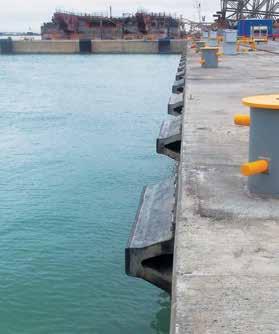
48 Super Arch and Arch Fenders Features Arch fenders are simple and rugged, providing reliable and trouble-free service for a wide variety of berths even under the most severe conditions. The SAN / AN-fender is a traditional rubber faced unit whilst the SANP / ANP-fender can be fitted with either UHMW-PE face pads or connected to a steel panel. Simple one-piece design Strong and hard wearing Excellent shear performance Large range of standard sizes Applications RoRo berths General cargo Workboat harbors Barge and tug berths 47
49 SAN / SANP Super Arch Fenders Dimensions Body Dimensions SAN / SANP Weight (kg/m) H A B W F D P Q SAN SANP SAN/SANP SAN/SANP SAN/SANP SAN/SANP SAN/SANP SAN/SANP SAN/SANP SAN/SANP SAN/SANP SAN Super Arch Fender SANP Super Arch Fender [Units: mm, kg/m] E FL E H D X Y Q P T B W F V U C A FL = L + H x 0.5 L ( Lmax) Foot Bolting Dimensions Fender Head Bolting Dimensions Fender Anchors / Head bolts ^ U V C L = 1000 L = 1500 L = 2000 L = 2500 L = 3000 E Qty E Qty E Qty E Qty E Qty SAN/SANP 150 M SAN/SANP 200 M SAN/SANP 250 M SAN/SANP 300 M SAN/SANP 400 M SAN/SANP 500 M SAN/SANP 600 M SAN/SANP 800 M SAN/SANP 1000 M UHMW-PE face pads Larger bolts are required when connecting SANP fenders to steel panels. Refer to your local offices. Steel frame X Y T Bolt size X Y [Units: mm] SANP M SANP M SANP M SANP M SANP M SANP M SANP M SANP M SANP M [Units: mm] ^ Fender anchors / head bolts indicated are based on fenders RDP performance using a particular grade of steel. Please contact Trelleborg Marine Systems local office for precise size, material and type for different grades of fenders pertaining to the project requirements. 48
50 SAN / SANP Super Arch Fenders Performance Data* E 1.0 E 1.1 E 1.2 E 1.3 E 1.4 E 1.5 E 1.6 E 1.7 E 1.8 E 1.9 E CV E R RPD E R R R CV E R RPD E R R R CV E R RPD E R R R CV E R RPD E R R R CV E R RPD E R R R CV E R RPD E R R R CV E R RPD E R R R CV E R RPD E R R R CV E R RPD E R R R [Units: knm, kn] *Note: 1. CV: performance data at slow speed constant velocity (2-8 cm/min) compression at 23 ±5 C temperature and 0 compression angle. 2. RPD: Rated performance data, in accordance with PIANC with initial high speed berthing velocity 0.15 m/s. RPD = CV (performance) x VF (velocity factor for Natural and Synthetic rubber blend) x TF (temperature factor) x AF (angle factor). RPD is reported at 23 ±5 C temperature and 0 compression angle, therefore TF = 1, AF = 1. 49
51 SAN / SANP Super Arch Fenders Performance Data* E 2.1 E 2.2 E 2.3 E 2.4 E 2.5 E 2.6 E 2.7 E 2.8 E 2.9 E CV E R RPD E R R R CV E R RPD E R R R CV E R RPD E R R R CV E R RPD E R R R CV E R RPD E R R R CV E R RPD E R R R CV E R RPD E R R R CV E R RPD E R R R CV E R RPD E R R R [Units: knm, kn] 3. For other initial berthing velocities, temperature and berthing angle, VF/ TF/ AF should be calculated separately and apply on CV performance to come to the final performance. 4. If fenders are tested in decreasing velocity (DV) mode at initial velocity 0.15 m/s, 0 compression angle and 23 ±5 C testing temperature, RPD = DV (performance). 5. Fender performance is subject to ±10% manufacturing tolerance (+10% for reaction force and -10% for energy). 50
52 SAN / SANP Super Arch Fenders Intermediate deflections D i (%) E i (%) R i (%) Nominal rated deflection may vary at RPD. Refer to the Performance Tolerances table in the Fender Application Design Manual. Generic curve shown. Actual curve geometry may vary depending on grade, temperature, velocity and angle. 51
53 AN / ANP Arch Fenders Lmax H A B W F D K E PxQ Anchors / Head bolts ^ AN Weight AN / ANP M AN / ANP M AN / ANP M AN / ANP M AN / ANP M AN / ANP M AN / ANP M AN / ANP M AN / ANP M ANP ^ Fender anchors / head bolts indicated are based on fenders RDP performance using a particular grade of steel. Please contact Trelleborg Marine Systems local office for precise size, material and type for different grades of fenders pertaining to the project requirements. [Units: mm, kg/m] AN Arch Fender ANP Arch Fender K E E K H D X Y Q P T B W F V U C A L ( Lmax) UHMW-PE Face Pads U V C X Y T Larger bolts are required when connecting ANP fenders to steel panels. Refer TMS. Bolt size X Steel Frame ANP M ANP M ANP M ANP M ANP M ANP M ANP M ANP M ANP M Y [Units: mm] L Anchors No No No No No No Non-standard lengths, profiles and bolting patterns are available on request. 52
54 AN Arch Fenders Performance Data* E 1.0 E 1.1 E 1.2 E 1.3 E 1.4 E 1.5 E 1.6 E 1.7 E 1.8 E CV E R RPD E R R R CV E R RPD E R R R CV E R RPD E R R R CV E R RPD E R R R CV E R RPD E R R R CV E R RPD E R R R CV E R RPD E R R R CV E R RPD E R R R CV E R RPD E R R R [Units: knm, kn] *Note: 1. CV: performance data at slow speed constant velocity (2-8 cm/min) compression at 23 ±5 C temperature and 0 compression angle. 2. RPD: Rated performance data, in accordance with PIANC with initial high speed berthing velocity 0.15 m/s. RPD = CV (performance) x VF (velocity factor for Natural and Synthetic rubber blend) x TF (temperature factor) x AF (angle factor). RPD is reported at 23 ±5 C temperature and 0 compression angle, therefore TF = 1, AF = 1. 53
55 AN Arch Fenders Performance Data* E 2.0 E 2.1 E 2.2 E 2.3 E 2.4 E 2.5 E 2.6 E 2.7 E 2.8 E 2.9 E CV E R RPD E R R R CV E R RPD E R R R CV E R RPD E R R R CV E R RPD E R R R CV E R RPD E R R R CV E R RPD E R R R CV E R RPD E R R R CV E R RPD E R R R CV E R RPD E R R R For other initial berthing velocities, temperature and berthing angle, VF/ TF/ AF should be calculated separately and apply on CV performance to come to the final performance. 4. If fenders are tested in decreasing velocity (DV) mode at initial velocity 0.15 m/s, 0 compression angle and 23 ±5 C testing temperature, RPD = DV (performance). 5. Fender performance is subject to ±10% manufacturing tolerance (+10% for reaction force and -10% for energy). [Units: knm, kn] 54
56 ANP Arch Fenders Performance Data* E 1.0 E 1.1 E 1.2 E 1.3 E 1.4 E 1.5 E 1.6 E 1.7 E 1.8 E CV E R RPD E R R R CV E R RPD E R R R CV E R RPD E R R R CV E R RPD E R R R CV E R RPD E R R R CV E R RPD E R R R CV E R RPD E R R R CV E R RPD E R R R CV E R RPD E R R R [Units: knm, kn] *Note: 1. CV: performance data at slow speed constant velocity (2-8 cm/min) compression at 23 ±5 C temperature and 0 compression angle. 2. RPD: Rated performance data, in accordance with PIANC with initial high speed berthing velocity 0.15 m/s. RPD = CV (performance) x VF (velocity factor for Natural and Synthetic rubber blend) x TF (temperature factor) x AF (angle factor). RPD is reported at 23 ±5 C temperature and 0 compression angle, therefore TF = 1, AF = 1. 55
57 ANP Arch Fenders Performance Data* E 2.0 E 2.1 E 2.2 E 2.3 E 2.4 E 2.5 E 2.6 E 2.7 E 2.8 E 2.9 E CV E R RPD E R R R CV E R RPD E R R R CV E R RPD E R R R CV E R RPD E R R R CV E R RPD E R R R CV E R RPD E R R R CV E R RPD E R R R CV E R RPD E R R R CV E R RPD E R R R [Units: knm, kn] 3. For other initial berthing velocities, temperature and berthing angle, VF/ TF/ AF should be calculated separately and apply on CV performance to come to the final performance. 4. If fenders are tested in decreasing velocity (DV) mode at initial velocity 0.15 m/s, 0 compression angle and 23 ±5 C testing temperature, RPD = DV (performance). 5. Fender performance is subject to ±10% manufacturing tolerance (+10% for reaction force and -10% for energy). 56
58 AN Arch Fenders Intermediate deflections Di (%) Ei (%) Ri (%) Nominal rated deflection may vary at RPD. Refer to the Performance Tolerances table in the Fender Application Design Manual Reaction (%) Deflection (%) 51.5% ANP Arch Fenders Intermediate deflections Energy (%) Di (%) Ei (%) Ri (%) Nominal rated deflection may vary at RPD. Refer to the Performance Tolerances table in the Fender Application Design Manual Reaction (%) Deflection (%) 54% Energy (%) 57
59 Super Arch and Arch Fenders Angle Factors (AF) Tranverse Load Energy Correction Factors A/H Deflection % at Point C Reaction Correction Factor Energy Correction Factor Reaction force is the maximum generated within the compression cycle. Correction factors may be used for any size and compound of the Arch and Super Arch Fender range. 58
60 Super Arch and Arch Fenders Angle Factors (AF) Longitudinal Load Energy Correction Factors L/H Reaction Force Correction Factors L/H Reaction force is the maximum generated within the compression cycle. Correction factors may be used for any size and compound of the Arch and Super Arch Fender range. 59
61 Super Arch and Arch Fenders Velocity Factor (VF) Table Compression time (seconds) Temperature Factor (TF) Table Temperature ( C) Blend of Natural and Synthetic Rubber (Catalog Compound) Blend of Natural and Synthetic Rubber (Catalog Compound) 100% Natural Rubber 100% Natural Rubber 100% Synthetic Rubber (SBR) VF VF VF Compression time needs to be calculated using the following formula: t = d/(ƒ*vd) Where: t = compression time (seconds)* d = rated deflection (mm) V d = initial berthing velocity (mm/s) ƒ = 0.74 deceleration factor (Peak reaction force occurs at between 30% - 40% deflection, where there has been a deceleration due to energy absorption. ƒ represents the factor associated with deceleration). * Applicable for both partial deflection and rated deflection. 100% Synthetic Rubber (SBR) TF TF TF


62 Corner Arch Fenders Berth corners are very difficult to protect. Corner Arch fenders are available in three standard sizes and provide a simple, easily installed solution to prevent damage from smaller vessels. Dimensions H L W B D F J K M Anchor Weight CA M20 80 CA M CA M [Units: mm, kg] Other corner fender solutions (contact your local office) Donut Wheels Fender Bars 61


63 new zealand 2. usa 3. azerbaijan 4. oman 5. hong kong 6. PHIlippines 7. poland 8. poland

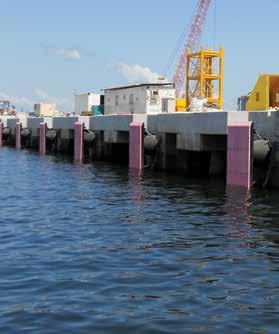
64 Parallel Motion Fenders Parallel Motion technology can reduce reaction forces by up to 60% compared with traditional designs. The panel always remains vertical but can cope with large berthing angles even at 20 there is usually no loss in energy absorption. Parallel Motion is a specialist fender system and its selection can only be used in consultation with local offices. Increasing energy, reducing reaction By using two Super Cones back-to-back, the deflection and energy both increase whilst reaction forces stay low. Reduced loads compared to conventional fenders mean less stress in the structure, allowing smaller piles and less concrete to be used. As Parallel Motion Fenders are mostly pre-assembled in the factory, installation is simple and fast. Maintenance is minimal too contributing to the low service life cost of Parallel Motion technology. Features Ultra-low reaction Non-tilt frontal panel No performance loss at large berthing angles Easy and fast to install Minimal maintenance Applications RoRo and fast ferry berths LNG and tanker terminals Naval facilities High tidal zones Monopile or soft structures 63


65 australia 2. United Kingdom 3. United Kingdom 4. Qatar 5. Sweden 6. United Kingdom 7. Norway 8. Denmark
66 Parallel Motion Fenders Comparison of PMF and conventional fenders Type Parallel Motion Fender PMF1200 (F3.1 & F1.9) Super Cone 2 SCN1200 (F2.8) Cell Fender 2 SCK1450 (E3.0) E (knm) R (kn) RPD % % % 20 Note: 1. = Relative Efficiency at 20º angle compared to PMF Performance at RPD. 3. Performance PMF softer cone taken at 75% deflection. 1 Rubber fender units Shown here are two Super Cones mounted in a back-to-back Twin-Series configuration. 2Closed box panel (frame) Fully sealed, pressure tested design. Shown with optional lead-in bevels which are designed to suit each case. 3 Torsion tube and arm assembly Also closed-box construction, the tube and arms keep the panel vertical whatever level impact loads are applied. 6 4 Hinge units The maintenance-free stainless steel pins and bearings allow free rotation to accommodate berthing angles, also eliminating moments in the hinge pin. 5 uhmw-pe face pads Trelleborg Double Sintered UHMW-PE face pads are standard to minimize friction and maximize service intervals Check chains (optional) Check chains act as rope deflectors to stop ropes from snagging, and to help with some large angle berthings Pile jackets (optional) Purpose designed for every project, pile jackets are factory built for a perfect fit to the fender onsite. They can strengthen the structure and double as a corrosion barrier in the vulnerable splash zone. Jackets are also available for monopile systems. 65

67 parallel motion fenders, sweden 66

68 Pivot Fenders Features Pivot fenders is an alternative and cost effective solution to the parallel motion fender type of applications. Simple and robust design Few fender elements are required compared to normal fender systems Simple assembly on site Parallel motion function Applications Belted vessel Roro ferries Cruise terminal Ports with wide tidal variation 67
69 Pivot Fenders It has a featured long legged panel normally fastened in a box at seabed level, allowing parallel movement of the panel when vessels are berthing. It is a useful solution for ports in which belted ships are commonly operated. Due to its unique design, pivot fender system allows the fender to rotate and follow the ship s berthing angle. The advantage of this design is that the energy absorbing rubber units absorb the full berthing energy irrespective of the point of contact of the vessel on the panel. However, the reaction force generated by the fender towards the vessel side will vary depending upon the point of contact Rubber fender units MV type shown 2 2 Pivot steel panel 3 Bottom connection Different solutions available. Please contact Trelleborg Marine Systems for further information. 4 Wear pads Standard UHMW-PE thickness at mm 3 68

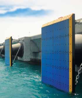
70 Flexible Wall (Type I) Features Individual fender systems are connected via steel hinges on their panels to create a flexible wall of fender system. The steel hinges between fender panels prevent the vessel from hitting the berthing structure at all times. Increases port performance and safety Small fender can be used compared to normal user design Steel hinges can be used to connect the steel panels as opposed to using chain links Well proven design helps to reduce fender size Applications Roro ferries Belted vessels Cruise terminal Container vessel Offshore platforms 69

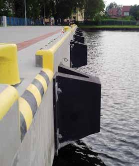
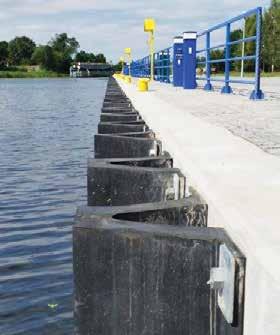
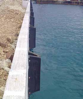
71 Flexible Wall (Type II) Another type of flexible wall that Trelleborg Marine Systems offers is leg fenders (MV, UE or Arch fenders) with the UHMW-PE shield placed continuously next to each other. This special design ensures the fender system is continually built along the quay. This can also be built on a corner with a special rubber connector, making sure that even corners with radius are safely protected. Features Increases port performance and safety Continuous UHMW-PE shield Applications Pier ends Exposed dolphins 70

72 Slide-In, Slide-Out Fender Systems Utilizing removable sliding panels, the patented Slide-In, Slide-Out (SISO) fender system has been designed to significantly reduce the time and effort taken to complete a fender wear pad change-out. Unlike traditional fender frame systems where ultra-high-molecular-weight polyethylene (UHMW- PE) wear pads are assembled directly onto a fixed frontal frame via a bolt fastening arrangement, the UHMW-PE wear pads are bolted onto two stainless steel removable panels. These panels are then inserted into a guide rail on the front face of the fixed frontal frame. The sliding panels can then be easily lifted out of the frontal frame and replacements reinserted within a couple of hours reducing downtime on the berth and keeping operations running punctually. The original panels can then be transported onshore for maintenance and have their wear pads replaced, ready to be used as spares for the next fender wear pad change-out operation. The system also reduces the safety risks and downtime associated with completing a pad replacement procedure from either a workboat or when using a maintenance scaffold system. Features Removable sliding panels Replaceable wear pads Simple and quick maintenance Applications General cargo berths Bulk terminals Oil and LNG facilities Container berths RoRo and cruise terminals Parallel motion systems 71
73 Slide-in, Slide-out Fender Systems 9 4 Slide-in, Slide-out (SISO) panel Removable panel with UHMW-PE wear pads. Allows rapid changeout of wear pads by replacing entire panel with a replacement panel Jacking and lifting points Allows SISO panel to be released from marine growth and lifted out for refurbishment Low friction inner pads Inner UHMW-PE pads to allow SISO panel to slide. 7 Corner protector Protects vessels from impacting fender frame corner. 8 Rope guard Prevents mooring lines from getting caught underneath fender panel Hawser rail Access platform Allows quick land-based access to release mechanisms for SISO system. Can be lifted into place by small crane for rapid deployment and designed to suit any type of wharf/dolphin structure Approach stairs Can be deployed quickly in conjunction with access platform and designed to suit any type of wharf/ dolphin structure. 12 Tension chain system 13 Weight chain system Shown here with optional chain shock absorber. 1 Rubber fender unit SCK type shown here but SCN types can also be used. 2 Closed box panel (frame) with SISO guide channel Fully sealed, pressure tested design with guide channels to hold sliding panels in place. 14 Uplift chain system Shown here with optional chain shock absorber. 15 Detention chain system Allows controlled release of tension in tension, weight or uplift chain systems during changeout procedures using hydraulics. 3 Dolphin headstock Fully sealed, pressure tested design with chain lug points and fender mounting ferrules. 72

74 Accessories Our ultra high molecular weight polyethylene (UHMW- PE) is the first choice material for facing steel fender panels and other heavy duty applications. All our accessories are procured from a pre-approved, reputable supplier. We ensure that our suppliers use the highest grade of raw materials to produce the best quality products and we test accessories quality when they arrive with us. We can also supply both open link or stud link chains in several grade strengths. Accessories such as shackles and U-anchors are also available. The nominal breaking load (NBL) of these items is matched to chains of similar capacity. Chains and accessories are galvanized as standard. Chain brackets may also be supplied in an optional painted finish. 73
75 Fender Accessories Super cone fender 2 Steel frontal frame 3 Chamfered edge on frontal frame 4 UHMW-PE facing pads 5 Fixing bolts for UHMW-PE pads 6 Weight chain 7 Tension chain 8 Shear chain 9 Chain tensioner 10 Chain shackle 11 NC3 type anchor 12 Bracket 13 Foot bolt 14 Head bolt 74
76 Fender Panels Fender panels are just as important as the rubber units on high performance systems. That s why every panel can be purpose designed using structural analysis programs and 3D CAD modelling for optimum strength. Fender panels distribute reaction forces to provide low hull pressures and cope with large tidal variations. They can also be designed to resist line loads from belted ships, or even point loads in special cases. Optional lead-in bevels reduce the snagging risk, whilst brackets (where required) provide highly secure connection points for chains. Closed box designs are used almost exclusively all fully sealed and pressure checked. Corrosion protection is provided by high durability C5M class paint systems to ISO 12944, and additional corrosion allowances can be designed in where required. Features and options Closed box steel structure Internal structural members blind boss fender connections Pressure tested for water tightness c5m modified epoxy paint* Polyurethane topcoat (RAL5005 blue) Studs for UHMW-PE face pads chain brackets lifting points lead-in bevels and chamfers * Other options available Alternative colours on request Specification and design of panels Panel specifications and designs should consider: Hull pressures and tidal range lead-in bevels and chamfers bending moment and shear local buckling limit state load factors Steel grade Permissible stresses weld sizes and types Pressure test method rubber fender connections UHMW-PE attachment chain connections lifting points Paint systems corrosion allowance maintenance and service life 75
77 Fender Panels 1 closed box steel structure 2Internal structural members 3 blind boss fender connections 4 Shot blasted steel (SA2.5) 5 c5m modified epoxy paint* 6 Polyurethane topcoat (RAL5005 blue) 7 Studs for UHMW-PE face pads 8chain brackets 9lifting points 10 lead-in bevels and chamfers* * Other options available Alternative colours on request Steel properties Standard GB/T 700 GB/T 1591 EN JIS G-3101 ASTM Grade Yield Strength (min) Tensile Strength (min) Test temperature of (v-notched) charpy impact test N/mm 2 psi N/mm 2 psi C F Q235B Q275B Q345B Q345C S235JR (1.0038) S275JR (1.0044) S355J2 (1.0570) S355J0 (1.0553) SS SS SM A A The national standards of France and Germany have been replaced by EN In the UK, BS4360 has been replaced by BS EN The table above is for guidance only and is not comprehensive. Actual specifications should be consulted in all cases for the full specifications of steel grades listed and other similar grades. Steel thickness (in accordance with PIANC 2002) Exposed both faces 12 Exposed one face 9 Internal (not exposed) 8 [Units: mm] Corresponding minimum panel thickness will be mm (excluding UHMW-PE face pads) and often much greater. Typical panel weights Light duty Medium duty Heavy duty Extreme duty 400 [Units: kg/m 2 ] 76
78 Ultra High Molecular Weight Polyethylene (UHMW-PE) The contact face of a fender panel helps to determine the lifetime maintenance costs of a fender installation. UHMW-PE is the best material available for such applications. It uniquely combines low friction, impact strength, nonmarking characteristics and resistance to wear, temperature extremes, seawater and marine borers. UHMW-PE is molded into plates at extremely high pressure and is a totally homogeneous material which is available in many sizes and thicknesses. These plates can be cut, machined and drilled to suit any type of panel or shield. Features Very low friction coefficient Excellent abrasion resistance UV and ozone resistant Does not rot, split or crack 100% recyclable Applications Fender panel (frame) face pads Rubbing strips V-fender shields Lock entrance and wall protection Bridge buttress protection Beltings on workboats Property Test Method Unit Virgin Typical Value Regenerated Density ISO g/cm Notched Impact Strength (Charpy) ISO kj/m Abrasion Index (Sand-slurry) ISO/DIS 15527(Draft) Yield Strength ISO/R 50mm/min N/mm Elongation at Break* ISO/R 50mm/min % > 50 > 50 Dynamic Friction (PE-Steel) Hardness Pm = 1N/mm 2 V = 10m/min ISO 868 / DIN s value, 6mm sample Shore D Operating Temperature C 80 to to +80 Thermal Expansion DIN K Molecular Weight Viscometric g/mol 4,200,000 4,200,000 Melting Point ASTM D3418 C All values for black, UV stabilized material. Values for colored materials will vary. Actual properties will be confirmed on order. * Alternative test methods such as ASTM 0638 give higher values circa 350%. 77
79 Ultra High Molecular Weight Polyethylene (UHMW-PE) Wear allowances Application t (mm) W* (mm) Bolt Light duty M16 Medium duty M16 M Heavy duty M24 M Extreme duty M30 M36 * Where allowances are typical values, actual wear allowance may vary due to fixing detail. Small increases in facing thickness can greatly extend service life for minimal extra cost. Typical dimensions A B C D E 5 10 [Units: mm] Dimensions will depend on pad thickness and application. [Units: mm] Large pads vs small pads Larger pads are usually more robust but smaller pads are easier and cheaper to replace. The standard color is black, but UHMW-PE is available in many other colours if required. 78
80 Chains Some fender systems need chains to help support heavy components or to control how the fender deflects and shears during impact. Open link or stud link chains are commonly used and these can be supplied in several different strength grades. Features Choice of open or stud link chains Various link lengths available Proof load tested and certified Galvanized as standard Variety of matched accessories Applications Large fender panels Cylindrical fenders Floating fender moorings Safety applications Lifting and installing Typical Chain System Anchors and fixing bolts Chain bracket Alloy D or bow-shackle with safety pin Chain tensioner Open or stud link chain Frontal frame bracket Frontal frame 79
81 Chains Open Link Chains ØC 3.0D links 3.5D links 4.0D links 5.0D links MBL L W Weight L W Weight L W Weight L W Weight SL2 SL [Units: mm, kg/link, kn] MBL = Minimum Breaking Load (kn) NBL = Nominal Breaking Load (kn) Tolerance: all dimensions ± 2.5% Stud Link Chains ØC Common link MBL L W Weight SL2 (U2) SL3 (U3) [Units: mm, kg/link, kn] Chain Tensioners Chain size ØA L W Weight 16 M M M M M M M M M M M M M M M [Units: mm, kg] 80
82 High Strength Shackles Dee shackle Bow shackle ØD ØF ØH G NBL E Weight E ØJ Weight Please refer to your local office for detailed information [Units: mm, kg, kn] Dee Bow U-Anchors ØD E F G J K t Weight NBL [Units: mm, kg, kn] 81
83 Brackets A B C E Single Lug Twin Lug F Ød R t T CB1/CB3 CB2 Shackle ØD Bolt Pin ØD Anchor M24 x /4 x M M24 x /4 x M M30 x /4 x M M30 x /4 x M M36 x /4 x M M36 x /4 x M M42 x /4 x M M42 x /4 x M M48 x /4 x M42 S-Series [Units: mm, kn] T-Series ± CB1 CB2 CB3 All chain and accessory information is for guidance only. Every chain design should be checked to confirm suitability for the intended application. Select chain system components so MBL NBL. Every chain system is different. Check all dimensions for fit, clearance and tolerance. Chain brackets can be specified with 2 or 4 anchors to suit application and loads. If extra long life is required, add a corrosion allowance. Some slack in the chain is unavoidable and will not affect operation. For special sizes and applications, please refer to Trelleborg Marine Systems local office. 82

84 Fender Fixings NC3 Anchors Thread A C ØF L S (sq) T Weight M M M M M M M M M M M Anchors available in mid steel, HDG, SS 316 or super duplex [Units: mm, kg] The NC3 is a traditional cast-in anchor design used for installing fenders to new concrete. The NC3 anchor has a threaded socket, a long tail and a square anchor plate. Non-standard sizes and other cast-in anchor types are available on request. Always check min/max clamping thickness and socket depths actual threaded length on bolts. EC2 Anchors Thread B E G J L (typ.) ØS Capsule Weight M C M C M C M C M C M C M C M C M C C M C A = E + G + H + J, rounded up to nearest 10mm. E = clear threads after assembly. H = clamping thickness of fender. The EC2 anchor is used for installing fenders onto existing concrete or where cast-in anchors are unsuitable. The anchor is usually secured into a drilled hole using special grout capsules. Non-standard sizes and other grout systems are available on request. [Units: mm, kg] Always follow the manufacturer s instructions when installing EC2 anchors. 83
85 Fender Fixings Bolts, Nuts and Washers Thread area * Washers Nuts # Typical thread lengths Thread Size (mm 2 ) OD ID t Weight AF T Weight L 125 L>125 pitch M M M M M M M M M M * Standard bolts given according to DIN933. Standard washers given according to DIN125. Larger OD washers available on request. Thread lengths may vary depending on standard. Other lengths available. # Standard nuts given according to DIN934. [Units: mm, kg] Grades ISO 898 Galvanized ISO 356 Stainless Steel * Bolt grade A-50 A-70 Nut grade 4 8 A-50 A-70 Tensile strength (MPa) % yield stress (MPa) * refer to Fender Application Design Manual for further details about PREN and galling. Size M39 unless agreed with manufacturer. Size M24 unless agreed with manufacturer. Fenders must be properly fixed to operate correctly. Anchors are supplied to suit new or existing structures, in various strength ratings and with the choice of galvanized or various stainless steels. 84

86 Disclaimer Trelleborg AB has made every effort to ensure that the technical specifications and product descriptions in this catalog are correct. The responsibility or liability for errors and omissions cannot be accepted for any reason whatsoever. Customers are advised to request a detailed specification and certified drawing prior to construction and manufacture. In the interests of improving the quality and performance of our products and systems, we reserve the right to make specification changes without prior notice. All dimensions, material properties and performance values quoted are subject to normal production and testing tolerances. This catalog supersedes the information provided in all previous editions. If in doubt, please check with Trelleborg Marine Systems. Trelleborg AB, PO Box 153, Trelleborg, Sweden. This catalog is the copyright of Trelleborg AB and may not be reproduced, copied or distributed to third parties without the prior consent of Trelleborg AB in each case. BC-FEN-v3.5-EN,

87 For a smarter approach to your next project, get in touch today. marinesystems@trelleborg.com 86
Rolling Fenders & Safety Products Product Brochure
 Trelleborg MARINE SYSTEMS Rolling Fenders & Safety Products Product Brochure The Smarter Approach Transferring know-how for smarter LNG The smarter approach for a more efficient port Materials best practice
Fender Systems. Trelleborg Marine Systems Make Certain
 Fender Systems Trelleborg Marine Systems Make Certain Fender Systems Make Certain Make Certain Shipping never stops and neither can you if you want to keep your clients happy. Trelleborg Marine Systems
Multipurpose & Tug Fenders Product Brochure
 Trelleborg MARINE SYSTEMS Multipurpose & Tug Fenders Product Brochure The Smarter Approach Transferring know-how for smarter LNG The smarter approach for a more efficient port Materials best practice for
ESC MARINE FENDER CATALOGUE 2018/2019 Edition DELIVERING COMPLETE MARINE FENDER SYSTEMS TO THE GLOBAL MARKET DOWNLOAD OUR APP ESC GROUP
 DELIVERING COMPLETE MARINE FENDER SYSTEMS TO THE GLOBAL MARKET www.escmarinesystems.com An Affiliate Of: ESC MARINE FENDER CATALOGUE 2018/2019 Edition DOWNLOAD OUR APP ESC GROUP About ESC ESC has been
About TekMarine. Disclaimer. Copyright
 Marine Fenders About TekMarine From its base in the United States, TekMarine Systems LLC designs and supplies advanced marine fendering and mooring systems to ports, harbors and waterways across the world.
Pneumatic Fender solutions with market leading service and support
 Pneumatic Fender solutions with market leading service and support Pneumatic Fenders from Trelleborg and Teekay CONTENTS SECTION ONE P.2 Introduction SECTION TWO P.3 The Halo Effect SECTION THREE P.4-5
Floating Fenders Product Brochure
 Trelleborg MARINE SYSTEMS Floating Fenders Product Brochure The Smarter Approach Transferring know-how for smarter LNG The smarter approach for a more efficient port Materials best practice for a smarter
About TekMarine. Disclaimer. Copyright
 Marine Fenders About TekMarine From its base in the United States, TekMarine Systems LLC designs and supplies advanced marine fendering and mooring systems to ports, harbors and waterways across the world.
Trelleborg en g INeereD SYSTeMS Marine Fenders
 Marine Fenders Why Trelleborg Fenders? There is a simple reason to use our fenders: it is just too expensive not to do so. Every modern marina, port or harbour invests in the protection of their structures
PROPULSION EQUIPMENT DOCUMENTATION SHEET. Propulsion Equipment
 PROPULSION EQUIPMENT General Vessels like rescue boats, patrol boats and anchor handling boats have to show 100 percent performance, even in the most extreme conditions. These so called s pecial seagoing
MARINE FENDERS Cell or Cone Type HCF SERIES
 MARINE FENDERS Cell or Cone Type HCF SERIES 1. GENERAL INTRODUCTION With successful service record dating back to 1972, HERCULES Elastomeric Energy Absorbing Devices (eg HVB) have been widely used worldwide
About TekMarine. Disclaimer. Copyright
 Marine Fenders About TekMarine From its base in the United States, TekMarine Systems LLC designs and supplies advanced marine fendering and mooring systems to ports, harbors and waterways across the world.
Pneumatic Fender solutions with market leading service and support
 Pneumatic Fender solutions with market leading service and support Pneumatic Fenders from Trelleborg and Teekay CONTNTS SCTION ON P.2 I n t r o d u c t i o n SCTION TWO P.3 T h e H a l o f f e c t SCTION
Pneumatic and Rolling Fenders. Pneumatic Hydropneumatic Wheel Fenders Roller Fenders Cushion Rollers
 Pneumatic and Rolling Fenders Pneumatic Hydropneumatic Wheel Fenders Roller Fenders Cushion Rollers 4 2 PNUMATIC FNDRS Pneumatic fenders are ideal for permanent and semi-permanent port applications and
MARINE FENDERS ISO EDITION FLOATING FENDERS SYSTEM FENDERS FIXED FENDERS ROPES & RIGGING SERVICE. noreqfender.no
 ISO 17357 MARINE FENDERS 2016 EDITION NPF3365CTN delivered to Haugesund Port summer 2015 FLOATING FENDERS ROPES & RIGGING SYSTEM FENDERS FIXED FENDERS SERVICE Fender davits Ropes, wire, hardware Quay and
About TekMarine. Disclaimer. Copyright
 Marine Fenders About TekMarine From its base in the United States, TekMarine Systems LLC designs and supplies advanced marine fendering and mooring systems to ports, harbors and waterways across the world.
ReadyMoor Series II. ReadyMoor Series II Quick Release Hooks and Capstans. Efficient cost effective mooring solutions off the shelf. Ready to go.
 Trelleborg MARINE SYSTEMS ReadyMoor Series II ReadyMoor Series II Quick Release Hooks and Capstans Trelleborg Marine Systems has developed a standardized series of Quick Release Hooks (QRHs) to meet a
Marine fendering. for quality rubber protection
 Marine fendering for quality rubber protection TABLE OF CONTENTS Marine fendering 4 W fenders 43 5 M fenders 47 Made to order 6 51 7 55 Repair market 9 58 D fenders 11 Wing fenders 60 Delta fenders 19
About TekMarine. Disclaimer. Copyright
 Marine Fenders About TekMarine From its base in the United States, TekMarine Systems LLC designs and supplies advanced marine fendering and mooring systems to ports, harbors and waterways across the world.
Hot Runners and Temperature Controllers
 Hot Runners and Temperature Controllers Better parts, faster cycles Benefits Complete tooling solutions Application specific solutions Pristine gate quality Fastest cycles Fast color change Accurate, reliable
ALL TERRAIN TRANSPORTERS WORLDWIDE HEAVY TRANSPORTATION AND LIFTING
 ALL TERRAIN TRANSPORTERS WORLDWIDE HEAVY TRANSPORTATION AND LIFTING Together, we are... SMARTER SAFER STRONGER At the heart of ALE s business are our people: dedicated professionals who work with our clients
Pipe gasket range. Designed to make a difference. Designed to make a difference 1
 Pipe gasket range Designed to make a difference Designed to make a difference 1 How Gulf gaskets can make a difference to you Water, drainage, sewerage - when it comes to sealing pipes, it s clear that
Shipboard fittings and supporting hull structures associated with towing and mooring on conventional vessels ships
 (Jan 2004) (Corr.1 Feb 2004) Rev.1 July 2004) (Rev.2 Sept 2006) (Rev.3 July 2007) (Corr.1 Sept 2014) (Rev.4 Oct 2016) Shipboard fittings and supporting hull structures associated with towing and mooring
A FLEXIBLE ALL-ROUNDER DIESEL-ELECTRIC MODEL 4 MOBILE HARBOR CRANES
 A FLEXIBLE ALL-ROUNDER DIESEL-ELECTRIC MODEL 4 MOBILE HARBOR CRANES 2 Gottwald Mobile Harbor Cranes Gottwald Mobile Harbor Cranes 3 MODEL 4 MOBILE HARBOR CRANES AS VERSATILE AS IT IS COMPACT Gottwald Model
ALGA/ALGAS SERIES PNEUMATIC ACTUATORS ALGA/ALGAS PNEUMATIC ACTUATORS
 ALGA/ALGAS SERIES PNEUMATIC ACTUATORS ALGA/ALGAS PNEUMATIC ACTUATORS A WORLD OF EXPERIENCE Biffi has been a leading manufacturer of valve actuators for more than 50 years. As one of the few manufacturers
Why Choose Rexnord? 866-REXNORD/ (Within the U.S.) (Outside the U.S.)
 (Outside the U.S.)") 866-REXNORD/866-739-6673 (Within the U.S.) 414-643-2366 (Outside the U.S.) www.rexnord.com Why Choose Rexnord? When it comes to providing highly engineered products that improve productivity and efficiency
866-REXNORD/866-739-6673 (Within the U.S.) 414-643-2366 (Outside the U.S.) www.rexnord.com Why Choose Rexnord? When it comes to providing highly engineered products that improve productivity and efficiency
Powering the most advanced energy storage systems
 Powering the most advanced energy storage systems Greensmith grid-edge intelligence Building blocks for a smarter, safer, more reliable grid Wärtsilä Energy Solutions is a leading global energy system
CONSISTENT TOP PERFORMANCE DIESEL-ELECTRIC MODEL 8 MOBILE HARBOR CRANES
 CONSISTENT TOP PERFORMANCE DIESEL-ELECTRIC MODEL 8 MOBILE HARBOR CRANES 2 3 MODEL 8 MOBILE HARBOR CRANES A CARGO HANDLING CRANE IN A CLASS OF ITS OWN Gottwald Model 8 Mobile Harbor Cranes are extremely
AquaMatic Control Valves, Stagers and Controllers
 Pentair Water is a leader in high technology flow control products and provides innovative solutions for commercial and industrial applications. AquaMatic valves, stagers and controllers are key components
ROBERTO BERNACCHI, GLOBAL PRODUCT MANAGER, 16 JUNE 2018 New power infrastructure concept for greener container terminals Creating Stronger, Smarter
 ROBERTO BERNACCHI, GLOBAL PRODUCT MANAGER, 16 JUNE 2018 New power infrastructure concept for greener container terminals Creating Stronger, Smarter and Greener port grids 1 greener Stronger, smarter and
Guide units. For toolmaking, fixture manufacturing and machine engineering
 Guide units For toolmaking, fixture manufacturing and machine engineering Guide units in compliance with DIN, ISO and STEINEL standards or according to your specifications Guide pillars Guide and pillar
Shipboard fittings and supporting hull structures associated with towing and mooring on conventional ships
 (Jan 2004) (Corr.1 Feb 2004) Rev.1 July 2004) (Rev.2 Sept 2006) (Rev.3 July 2007) (Corr.1 Sept 2014) (Rev.4 Oct 2016) (Corr.1 Dec 2016) (Corr.2 Mar 2017) Shipboard fittings and supporting hull structures
Weigh Module. Selection Guide.
 Weigh Module Selection Guide www.rlws.com selecting weigh modules Selecting Weigh Modules How to be Confident You re Installing The Best Low-quality, poorly-constructed weigh modules most often result
D-M-E Mold Base and Plate Services. The fastest delivery of standard mold bases, special mold bases, and contour roughed mold plates
 D-M-E Mold Base and Plate Services The fastest delivery of standard mold bases, special mold bases, and contour roughed mold plates 14 Mold Base and Plate Services Table of Contents D-M-E Edge Mold Bases...
ROLL-UP COVERS Standard products
 A ROLL-UP COVERS Standard products P.E.I. Roll-up Covers are normally equipped with our patented system of multiple springs. This offers countless advantages: Reliability Compact size Extremely high speeds
ENGINE DRIVES AND COUPLINGS
 LEADING BY INNOVATION ENGINE DRIVES AND COUPLINGS PRECISION ENGINEERED ENGINE DRIVES FOR INDUSTRIAL EQUIPMENT, CONSTRUCTION & HYDRAULIC POWER, WORKBOATS, PLEASURE BOATS, FAST FERRIES, CRUISE SHIPS, CARGO
Above. Ahead. Always.
 Above. Ahead. Always. All Terrain Cranes. Crawler Cranes. Above. Ahead. Always. Demag constantly designs, develops and delivers smart lifting technologies that go above expectations to benefit your business.
Transportation Products
 Transportation Products Butterfly Valves Hopper Tees Actuators Accessories A Name You ve Trusted for Years... Resilient Seated Butterfly Valves 400 & 480 Series 1 Piece Body Design This economical, resilient
MAN 175D. 100 % Marine. 100 % High Speed.
 MAN 175D 100 % Marine. 100 % High Speed. 2 3 Ever since we steered the marine industry out of the steam age, MAN has been setting the standard for diesel engines. It s a history of undisputed reliability,
Altra Industrial Motion. AquaMaKKs Water Cooled Clutches and Brakes with Composite Water Jackets
 Altra Industrial Motion AquaMaKKs Water Cooled Clutches and Brakes with Composite Water Jackets AquaMaKKs Water Cooled Clutches and Brakes AquaMaKKs water cooled clutches and brakes are designed to provide
SKF linear motion solutions for medical equipment
 SKF linear motion solutions for medical equipment The Power of Knowledge Engineering The way to care In today s medical world, comfort and safety are key requirements. Hospital environments become more
Wind Power Solutions
 Wind Power Solutions Because ensuring a leak-free solution is critical. It has to be Hydratight. For more than 100 years, Hydratight has provided world-class bolted joint solutions, assessing and managing
Standard with cone bushing. Backlash-free Safety Clutch
 EAS -Compact ratchetting clutch/synchronous clutch The Backlash-free Safety Clutch for Standard with cone bushing Packaging Machinery Machine Tools Paper Machinery Indexing Drives Servo Motors EAS -NC
Come across. m o d u l a r s o l u t i o n s
 Come across B R I D G E S P O N T O O N S R O R O S m o d u l a r s o l u t i o n s Design, manufacturing, erection on site in rent and or sale Janson Bridging. Leading the way in modular solutions Janson
Demag DH hoist units. The solution to meet special requirements
 Demag DH hoist units The solution to meet special requirements 1 Demag DH hoist units for solutions beyond classic crane applications Synchronised DH hoist units lift and lower a roof segment in a shopping
UNCOMPROMISING HANDLING PERFORMANCE DIESEL-ELECTRIC MODEL 7 MOBILE HARBOR CRANES
 UNCOMPROMISING HANDLING PERFORMANCE DIESEL-ELECTRIC MODEL 7 MOBILE HARBOR CRANES 2 3 MODEL 7 MOBILE HARBOR CRANES OUTSTANDING PERFORMANCE FOR TOUGH APPLICATIONS Gottwald Model 7 Mobile Harbor Cranes are
DuraBlue Composite Water-Lubricated Stern Tube Bearings
 ADVANCED WATER-LUBRICATED BEARING SYSTEMS DuraBlue Composite Water-Lubricated Stern Tube Bearings E Pollution Free E Dimensionally Stable, Long Wear Life E Ultra-Low Friction, High Load Capabilities PRODUCT
EXTRA LARGE VALUE IN CARGO HANDLING DIESEL-ELECTRIC MODEL 5 MOBILE HARBOR CRANES
 EXTRA LARGE VALUE IN CARGO HANDLING DIESEL-ELECTRIC MODEL 5 MOBILE HARBOR CRANES 2 3 MODEL 5 MOBILE HARBOR CRANES FUNCTIONAL DESIGN AND POWERFUL PERFORMANCE Gottwald Model 5 Mobile Harbor Canes are very
Why Choose Rexnord? 866-REXNORD/ (Within the U.S.) (Outside the U.S.)
 (Outside the U.S.)") 866-REXNORD/866-739-6673 (Within the U.S.) 44-643-366 (Outside the U.S.) www.rexnord.com Why Choose Rexnord? When it comes to providing highly engineered products that improve productivity and efficiency
866-REXNORD/866-739-6673 (Within the U.S.) 44-643-366 (Outside the U.S.) www.rexnord.com Why Choose Rexnord? When it comes to providing highly engineered products that improve productivity and efficiency
Transportation Valves
 Transportation Valves A Name You ve Trusted for Years... 780 Series Butterfly Valves Features: Available in sizes 3 thru 6 One handle fits sizes 3 thru 6 Integrated 180º notch plate eliminates mounting
Power. Solutions for the Overhead Crane & Hoist Market. Warner Electric. Twiflex Limited. Bauer Gear Motor. Ameridrives Couplings.
 Altra Industrial Motion Warner Electric Twiflex Limited Bauer Gear Motor Ameridrives Couplings TB Wood s Power Transmission Solutions for the Overhead Crane & Hoist Market Altra Industrial Motion Altra
OHV and OHVL Vertical Inline Pumps ISO (API 610)
") OHV and OHVL Vertical Inline Pumps ISO 3709 (API 60) Sulzer Pumps Sulzer Pumps is a leading global supplier of reliable products and innovative pumping solutions for end users. Our active research and
OHV and OHVL Vertical Inline Pumps ISO 3709 (API 60) Sulzer Pumps Sulzer Pumps is a leading global supplier of reliable products and innovative pumping solutions for end users. Our active research and
A Modular Product Line for Dust Free Loading
 A Modular Product Line for Dust Free Loading Enclosed Truck Loading Loading dusty bulk cargo into enclosed trucks and railcars can be made safely, economically and dust free using pre-engineered interchangeable
Belts for the Confectionery Industry. Your business is our business!
 NA Your business is our business! Belts for the Confectionery Industry Ammeraal Beltech knows your process for all your belting needs just-in-time delivery www.ammeraalbeltech.com We know your production
The reliable choice for the Oil and Gas industries
 Oil & Gas ASCO Fluid Automation Solutions The reliable choice for the Oil and Gas industries Due to our global presence, hazardous area expertise and a broad range of solenoid valves and actuator control
Rotating Power AC Motors and Generators
 Rotating Power AC Motors and Generators Preferred Partner Building on over one hundred years design experience and application understanding, ABB is the world s leading manufacturer of low and high voltage
A COMBINATION OF POWER AND FUNCTIONALITY DIESEL-ELECTRIC MODEL 6 MOBILE HARBOR CRANES
 A COMBINATION OF POWER AND FUNCTIONALITY DIESEL-ELECTRIC MODEL 6 MOBILE HARBOR CRANES 2 3 MODEL 6 MOBILE HARBOR CRANES HIGH PERFORMANCE FOR HIGHER HANDLING RATES Gottwald Model 6 Mobile Harbor Cranes are
GE Marine. Seaworthy power. GE s new L250 inline diesel engine. imagination at work
 GE Marine Seaworthy power GE s new L250 inline diesel engine imagination at work GE s L250 Built by one of the world s largest manufacturers of medium-speed diesel engines Designed to save fuel and meet
TIMKEN SNT SPLIT PLUMMER BLOCKS
 TIMKEN SNT SPLIT PLUMMER BLOCKS TIMKEN SNT SPLIT PLUMMER BLOCKS 1 TABLE OF CONTENTS INTRODUCTION... 3 TIMKEN SNT SPLIT PLUMMER BLOCKS...4 SEAL OPTIONS AND DESCRIPTIONS...6 SEAL SELECTION AND CONFIGURATION
Rectiverter a new word and a new world in power conversion
 Rectiverter a new word and a new world in power conversion Introducing the world s first bidirectional power conversion module. The Rectiverter is a new concept in power conversion. It combines the functionality
ISOMOVE. Mechanical actuators ISO 6431
 ISOMOVE Mechanical actuators ISO 6431 ISOMOVE INDEX 2 Introduction 4 Mounting information and advices 6 10 40 14 20 63 25 80 29 33 Overall dimensions INTRODUCTION GENERAL FEATURES The ISOMOVE actuators
BULK FEED TANKS AND GRAIN HOPPER TANKS FARM HOPPER TANKS PROVEN & DEPENDABLE
 BULK FEED TANKS AND GRAIN HOPPER TANKS FARM HOPPER TANKS PROVEN & DEPENDABLE WWW.GRAINSYSTEMS.COM WHY GSI PROVEN & DEPENDABLE Only GSI feed tanks feature the exclusive, patented Auto-Lok ground control
INNOVATION INSIDE. SENSORS & TPMS COMPONENTS FLUID CONTROL & HIGHLY ENGINEERED VALVES TIRE HARDWARE, REPAIR & AIR ACCESSORIES
 INNOVATION INSIDE. For automotive and industrial leaders whose reputations ride on reliability, Schrader is the valve and sensing technology pioneer that delivers innovative solutions they can trust because
Bulk Fuel and Lubricants Storage Total Fuel and Lubricants Management Solutions
 Bulk Fuel and Lubricants Storage Total Fuel and Lubricants Management Solutions Safeguarding your assets. Protecting your business. Keeping your business moving We are the UK s largest independent supplier
SD25. VOLVO SINGLE DRUM COMPACTOR 2.7 t 31.4 kw
 SD25 VOLVO SINGLE DRUM COMPACTOR 2.7 t 31.4 kw A passion for performance. At Volvo Construction Equipment, we re not just coming along for the ride. Developing products and services that raise productivity
specialized in modular PONTOON solutions for various purposes and applications
 specialized in modular PONTOON solutions for various purposes and applications COMPANY Introduction / Market, rental, purchase or lease MPS is the exclusive manufacturer of MPS container pontoons and is
Power. Solutions for the Tidal Turbine Market. Twiflex Limited. Bibby Turboflex. A l t r a I n d u s t r i a l M o t i o n.
 A l t r a I n d u s t r i a l M o t i o n Wichita Clutch Twiflex Limited Bibby Turboflex Ameridrives Couplings Power Transmission Solutions for the Tidal Turbine Market A l t r a I n d u s t r i a l M
DRIVE SOLUTIONS FOR THE TYRE INDUSTRY DRIVESYSTEMS
 INTELLIGENT DRIVESYSTEMS, WORLDWIDE SERVICES EN DRIVE SOLUTIONS FOR THE TYRE INDUSTRY DRIVESYSTEMS NORD DRIVESYSTEMS Intelligent Drivesystems, Worldwide Services NORD DRIVE SOLUTIONS FOR THE TYRE INDUSTRY
SERVO-HYDRAULIC UNIVERSAL TESTING MACHINE SERIES D
 SERVO-HYDRAULIC UNIVERSAL TESTING MACHINE SERIES D STANDARD BS 8110: PART 1: 1997 3.12.8.16.2, BS4482. BS4483, BS4449, ASTM A 1034: 10.5, 10.7 TEST TYPE Slip & Tensile Strength Permanent Elongation & Tensile
HYDRAULIC ACTUATORS EC-SERIES. ELFORCONTROLS Actuators and Valves Automation
 HYDRAULIC ACTUATORS EC-SERIES ELFORCONTROLS Actuators and Valves Automation HISTORY Elfor Controls, established in the last 70 s, is an Italian company specialized in engineering and manufacturing of a
MECHANICAL Forging PRESSES WITH KNUCKLE-JOINT
 MECHANICAL Forging PRESSES WITH KNUCKLE-JOINT MML / MSL. Mechanical Forging Presses with knuckle-joint. From process development and cost-effective line concepts to full production lines. MECHANICAL Forging
Eco-friendly, efficient and safe eaht winch series electric anchor handling/towing solutions
 Eco-friendly, efficient and safe eaht winch series electric anchor handling/towing solutions eaht series winches Innovations that improve performance and protect the environment Fast, clean and precise
LHM 600. Mobile Harbour Crane
 Mobile Harbour Crane LHM 600 Maximum lifting capacity 208 t Maximum outreach 58 m Ship size New Panamax Very Large Bulk Carrier Ultra Large Container Vessel Main Dimensions Heavy Lift Operation Lifting
PRODUCTS AND CAPABILITIES ACTUATION & CONTROLS ACTUATION & CONTROLS PRODUCTS AND CAPABILITIES
 PRODUCTS AND CAPABILITIES ACTUATION & CONTROLS ACTUATION & CONTROLS PRODUCTS AND CAPABILITIES Complete automation solutions for a broad range of industries. 2 ACTUATION & CONTROLS AUTOMATION SYSTEMS CONTROLS
SERVICE AND REPAIR. On-Site Services Repairs, Overhauls & Upgrades Drop in Replacement Gearboxes Asset Management
 Product Brochure SERVICE AND REPAIR Radicon service engineers are ready and waiting 24 hours a day, 365 days a year, to provide the following services anytime, anywhere in the world. On-Site Services Repairs,
Because ensuring a leak-free solution is critical. It has to be Hydratight.
 Torque Solutions Because ensuring a leak-free solution is critical. It has to be Hydratight. For more than 100 years, Hydratight has provided world-class bolted joint solutions, assessing and managing
SPECIALTIES REFINERY. The definitive range in fuel treatment
 Energy Fuel Specialties Refinery Processing Liquid Yield Crude Oil Storage and Treatment Demulsifiers, Asphaltene Dispersants, Drag Reducers, Pour Point Depressants, Biocides, Corrosion Inhibitors, Combustion,
Engtek Manoeuvra Systems Pte Ltd
 Engtek Manoeuvra Systems Pte Ltd Tunnel Thruster Systems Marine Thruster & Propulsion Systems The enclosed data, information, description, photos and illustrations in this brochure are the property of
Global technology leader in the manufacture of wire and fibre rope solutions for the world s most demanding applications
 Oil and Gas Global technology leader in the manufacture of wire and fibre rope solutions for the world s most demanding applications Bridon Neptune Quay, a state-of-the-art manufacturing facility that
DODGE MECHANICAL. Grain industry Delivering solutions that solve industry challenges
 DODGE MECHANICAL Grain industry Delivering solutions that solve industry challenges 2 GRAIN INDUSTRY DELIVERING SOLUTIONS THAT SOLVE INDUSTRY CHALLENGES Mechanical power transmission products We help feed
SKF Energy Efficient deep groove ball bearings. Reduced friction for reduced energy use
 SKF Energy Efficient deep groove ball bearings Reduced friction for reduced energy use SKF Energy Efficient bearings Engineered to promote sustainability As the need to conserve energy grows more apparent
Flygt low-speed mixers OUTSTANDING EFFICIENCY
 Flygt low-speed mixers OUTSTANDING EFFICIENCY INTRODUCTION Energy-efficient mixing Advantages of Flygt low-speed mixers Rising to the mixing challenge All mixing applications require varying degrees of
Better sealing solutions for reciprocating compressors
 Better sealing solutions for reciprocating compressors Experience and know-how the basis for innovation Rings and packings are critical components for the service life of reciprocating compressors. Therefore
HIGH PERFOMANCE SERVO PRESS P2H-FX SERIES PRESSES TONS CAPACITY P2H-FX
 HIGH PERFOMANCE SERVO PRESS P2H-FX SERIES PRESSES 63-160 TONS CAPACITY P2H-FX P2H-FX SERVO TABLE OF CONTENTS 3 Key Features 4 Standard Features 5 Motion Profiles 7 Production Management Control (PMC) 8
Innovative Solutions
 Innovative Solutions 2 1 MK4 Introduction mk MK4 Elastomeric Bearings are deformable structural components constructed partially or wholly from elastomer. They are essentially designed to transmit vertical
Innovative Power Transmission T RECS. Leading Propulsion Technology
 Innovative Power Transmission T RECS 2 Leading Propulsion Technology Leading Propulsion Technology T 2 RECS: Rugged. Reliable. Safe. Marine gear units for the toughest challenges RENK marine gear units
Ball Rail Systems RE / The Drive & Control Company
 Ball Rail Systems RE 82 202/2002-12 The Drive & Control Company Rexroth Linear Motion Technology Ball Rail Systems Roller Rail Systems Standard Ball Rail Systems Super Ball Rail Systems Ball Rail Systems
COMPACT ACTUATORS COMPACT PNEUMATIC & HYDRAULIC ACTUATORS
 COMPACT ACTUATORS COMPACT PNEUMATIC & HYDRAULIC ACTUATORS A WORLD OF EXPERIENCE Biffi is a leading manufacturer of valve automation solutions with 60 years experience and a global presence, offering a
MULTI-PURPOSE FLOATING PLATFORMS
 MULTI-PURPOSE FLOATING PLATFORMS INDUSTRIAL APPLICATIONS Port Construction Port Expansion Offshore Storage Offshore Drilling Support Marine Offloading Facilities Breakwaters www.truenorthservicesllc.com
Crane systems. Marine Cranes
 Crane systems Marine Cranes Foldable Knuckle Boom Range PK Marine cranes from Palfinger systems have everything needed for tough daily applications. Optimised synergy of function and design. All safety
Aquadrive Antivibration System
 Aquadrive Antivibn System GKN Land Systems Aftermarkets & Services Headquarters: GKN Service International GmbH Nussbaumweg 19 21 51503 Rösrath, Germany www.gknservice.com www.aquadrive.com Art. No. 190213_10/2011
Specialist in Maritime Temperature Measurement
 Specialist in Maritime Temperature Measurement 1 ... guaranteeing you the best product and service Our experience, your guarantee Kjærulf Pedersen is one of the world s leading specialists in construction
The oil & gas industry driven by David Brown.
 www.davidbrown.com www.davidbrown.com The oil & gas industry driven by David Brown. David Brown Africa +27 11 748 0000 Australia +61 1300 32 4327 China +86 21 6334 3322 Europe +33 3 89 37 01 13 Thailand
Linear Drive with Ball Screw Drive Series OSP-E..SB
 Linear Drive with Ball Screw Drive Series OSP-E..SB Contents Description Data Sheet No. Page Overview 1.30.001E 47-50 Technical Data 1.30.002E-1 to 5 51-55 Dimensions 1.30.002E-6, -7 56-57 Order instructions
PERFECTLY POSITIONED FOR ANY CHASSIS.
 SUSPENSION SPRINGS PERFECTLY POSITIONED FOR ANY CHASSIS. Egon von RUVILLE GmBH Billbrookdeich 112 22113 Hamburg Germany Tel.: +49 40 73344-0 Fax: +49 40 73344-199 info@ruville.de www.ruville.de NEW IN
Reliable and powerful starting for diesel engines and generators
 When Power is Critical EN-1834-1 EN-1834-2 Reliable and powerful starting for diesel engines and generators HYDRAULIC STARTING SYSTEMS For diesel engines up to 80 litres IPU s hydraulic starting systems
It s a matter of honour to access your construction site. Junttan piling hammers
 It s a matter of honour to access your construction site Junttan piling hammers Strong arguments in high quality and functionality. Adjustable energy - Always the right impact energy to suit the soil conditions
XB IEC Terminal Blocks. Screw Type Insulation Displacement Connection Type
 XB IEC Terminal Blocks Screw Type Spring Cage Type Insulation Displacement Connection Type 2 XB IEC Terminal Blocks. Versatility, quality, and reliability. Sometimes it s the little things Eaton knows
ROLL-UP COVERS. Special Product: SURE-SPRING.
 Special Product: SURE-SPRING The P.E.I. Patented design known as SURE-SPRING represent the most advanced level of technical innovation in the field of roll-up covers. The spring mechanism design takes
Linear Actuator with Ball Screw Series OSP-E..S. Contents Description Overview Technical Data Dimensions 89
 Linear Actuator with Ball Screw Series OSP-E..S Contents Description Page Overview 79-82 Technical Data 83-88 Dimensions 89 79 The System Concept ELECTRIC LINEAR ACTUATOR FOR HIGH ACCURACY APPLICATIONS