ASME RC Baja Car: Suspension and Chassis
|
|
|
- Maximillian Dennis
- 6 years ago
- Views:
Transcription

1 Central Washington University All Undergraduate Projects Undergraduate Student Projects Spring 2017 ASME RC Baja Car: Suspension and Chassis C. Aidan Pringle Central Washington University, Follow this and additional works at: Part of the Mechanical Engineering Commons Recommended Citation Pringle, C. Aidan, "ASME RC Baja Car: Suspension and Chassis" (2017). All Undergraduate Projects This Undergraduate Project is brought to you for free and open access by the Undergraduate Student Projects at It has been accepted for inclusion in All Undergraduate Projects by an authorized administrator of For more information, please contact
2 ASME RC BAJA CAR: SUSPENSION & CHASSIS By Aidan Pringle Partner: Walter Lackey (Drivetrain & Steering)
3 Table of Contents ABSTRACT : INTRODUCTION a: Motivation: b: Function Statement: c: Requirements: d: Engineering Merit: e: Scope of Effort: d: Success Criteria: : DESIGN & ANALYSIS a: Approach b: Design Description c: Benchmark d: Performance Predictions e: Description of Analyses f: Scope of Testing and Evaluation g: Analyses h: Device: Parts, Shapes and Conformation i: Device Assembly k: Technical Risk Analysis : METHODS AND CONSTRUCTION a: Construction Description c: Parts list and labels d: Manufacturing issues e: Discussion of assembly, sub-assemblies, parts, drawings (examples) : TESTING METHOD a: Introduction b: Method/Approach c: Test Procedure d: Deliverables : BUDGET/SCHEDULE/PROJECT MANAGEMENT a: Budget b: Schedule c: Project Management
4 6: DISCUSSION a: Design Evolution / Performance Creep b: Project Risk analysis c: Successful d: Project Documentation e: Next phase CONCLUSION ACKNOWLEDGEMENTS REFERENCES APPENDIX A Analysis APPENDIX B Drawings and Assembly APPENDIX C Parts and Materials APPENDIX D Budget APPENDIX E Schedule APPENDIX G Testing Data APPENDIX I Testing Report APPENDIX J Resume
5 ABSTRACT Each year the regional chapter of the American Society of Mechanical Engineers (ASME) put on a Radio Controlled (R/C) Baja car competition. The R/C car designed for the competition must compete in two events, a slalom sprint and an obstacle course. A successfully designed car will not only be able to complete each event but also be competitive in each event. A main component to the success of the R/C car is the suspension. The suspension design for this year s car must operate effectively without interfering with the steering and drivetrain designed by Walter Lackey. The suspension utilizes a transverse leaf spring design which utilizes steel, aluminum, and 3D printed ABS plastic components. The components were designed using principals of statics and dynamics. Finite Element Analysis (FEA) was also used to verify the initial analysis and optimize the component geometry. The suspension components were designed to withstand a vertical impact from two feet off of the ground and a horizontal impact within a similar load. The result of the suspension design is a system that works flawlessly. The suspension system does not interfere with any other system of the car as it cycles through its full range of motion. It has completed the two foot drop test without failure and completed both events in the ASME competition. 1.a: Motivation: 1: INTRODUCTION The CWU R/C Baja car from 2016 suffered broken suspension parts during the competition. The CWU R/C Baja car for 2017 needs a redesigned and optimized suspension so that it will be able to successfully complete the ASME competition. With the suspension handled, Walter Lackey will be taking care of the drivetrain and steering on the car. 1.b: Function Statement: The R/C Baja car suspension must be able to support the weight of the car while enduring the ASME competition. 1.c: Requirements: The following list describes the design requirements for the 2017 R/C Baja car suspension. Full suspension travel of 2 without interference. Springs must support the weight of a four pound car. Suspension support the car dropping from 2 off the ground. Suspension must withstand the power from a 3.67 peak hp brushless electric motor. Suspension fasteners must be easily sourced standard size fasteners such as #4 and #6. As per ASME competition rules, design for parts interchangeability of 50% to allow for a smaller amount of spare parts. 1.d: Engineering Merit: 4

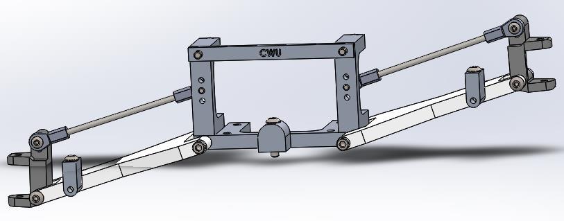
6 The engineering merit of this project is in the designing and optimizing of the R/C Baja car suspension. The suspension will be designed against a list of requirements that it will be tested against later on in the project. Each component in the suspension must be designed in such a way that the suspension will be able to function without binding or breaking. In addition to building a suspension that will be functional. The optimization of the suspension means it must also outperform the suspension systems from the previous CWU R/C Baja cars in one form or another. 1.e: Scope of Effort: The scope of the project is to design and build a 1/10 th scale R/C Baja car suspension system that complies with the ASME R/C Baja competition rules. The project will consist of solely designing the suspension system of the car around the existing chassis and that will operate together with my partners steering and drivetrain design. 1.d: Success Criteria: The success criteria for the R/C Baja car suspension will be to allow the car to successfully complete the ASME R/C Baja car competition. The suspension must be able to function fully in which it was designed as well as function effectively with the other components of the R/C Baja car. 2.a: Approach 2: DESIGN & ANALYSIS The proposed solution is a suspension and chassis for the ASME Baja car. The suspension will use a transverse leaf spring design for the front and rear of the car. The chassis will be the same design as the last two CWU Baja cars with the exception of a one inch longer length. 2.b: Design Description The design of the suspension system is a symmetrical independent suspension system using transverse leaf springs. Each component of the suspension is symmetrical. This reduces the amount of spare parts needed and reduces the time spent manufacturing parts. Because the differential needs to occupy a portion of the rear of the car, the differential assembly must fit within the rear suspension mounts. The rear hubs are fixed and supply power to the wheels while the front hubs must allow for the steering of the car. For these reasons, the hubs are the only non-symmetrical part of the suspension. Figure 5 shows the design of the suspension. The Figure B1: Baja Car Assembly figure does not illustrate the travel up and down. The nature of leaf springs requires adjustability in one end to allow the spring to change length 5
7 throughout its travel. In order to accommodate this, the shackle used to connect the leaf spring to the control arm can swivel to allow the change in length of the spring. 2.c: Benchmark The benchmark for this year s car will be the CWU Baja Car. The Baja car is in need of some repair before it will be operational. Once the car is up and running it will provide a benchmark for the CWU Baja Car. The intent will we be to improve upon as many parameters as possible that have been set by the previous model car. The car is a legitimate benchmark because it won the 2015 ASME Baja Car challenge. 2.d: Performance Predictions The desired performance of the suspension is to allow for two inches of suspension travel. One inch will be suspension compression and the other inch will be suspension droop. The leaf spring will need to be able to deflect the proper distance to allow for this suspension action. The amount of deflection needed in the spring will be determined by the location of the spring mount on the control arm. The spring thickness and leaf pack size is determined by a drop from two feet consuming the entire up travel of the suspension upon impact. The spring thickness calculation is shown in Figure A5 located in Appendix A. Throughout the suspension travel, the camber will be within plus or minus five degrees. The camber will go negative during suspension compression and positive during suspension extension. Each suspension component of the car will be able to withstand the weight of the car from a drop two feet off the ground. Each corner of the suspension will be able to withstand a load of four times the weight of the car. 2.e: Description of Analyses Because the main goal of the car was to complete the ASME R/C Baja Competition, the numerical parameters were not specific values. The numerical design requirements were chosen based on assumptions in the desired performance for the car. For instance, the springs were designed to a two foot vertical drop. The two foot value was chosen because it was assumed that a jump would be no greater than two feet. On to the control arm analysis. They were also designed to an assumed value. Going into the analysis, there was no data available to us to determine the stress that the car would see during a crash. The car was then designed to an impact of four times the car s weight. The weight of the car was also an assumed value for the analysis. The calculations done during the analysis on the car can be found in Appendix A. 2.f: Scope of Testing and Evaluation The suspension will be tested against the original requirements for the car. In order to fulfill those requirements, the car will go through a series of tests. These tests will either pass or fail against the requirement. A fully successful car will fulfil every requirement. The final evaluation 6

8 of the car will be in the ASME R/C Baja Competition. The cars ability to complete the competition will be a success. 2.g: Analyses The analyses required for the suspension system included the leaf spring pack spring rate and the strength of the suspension components. The component strength and design were based on the design requirements. Because the control arms are made of ABS plastic, a weaker material, and they are a complex design, the control arms were analyzed using FEA to get a better idea of the stresses they could handle. Using the FEA software, the arms were determined to be able to withstand the designed impact with a safety factor greater than N = 1.8. In the event of a crash, the control arms will likely break. Because of the limitations in space and strength, the arms will stay as they are. A bumper was added to help protect the control arms during a crash. Design Issues: The nature of a transverse leaf spring design requires the leaf spring to span from one control arm to the other. Therefore, the leaf spring spans across the area where the drivetrain and steering must reside. Mounting the leaf spring underneath the car or overtop of the differential were possible solutions but were deemed unacceptable. The proposed solution is to mount the leaf spring at the very end of the chassis. This allows sufficient clearance for the differential and steering. Given the nature of the suspension design, the set up can be the same for the front and rear of the car. Calculated Parameters: The calculated parameters for the car were in the springs and the control arms. The springs had spring rate requirements based on a vertical drop and the control arms had an impact requirement in the event of a crash. All of the calculations can be found in Appendix A. 2.h: Device: Parts, Shapes and Conformation The intent of the design thus far is purely functional. The shapes of the components like the control arms are designed in a way that fit the chassis and suspension components the best. The designs are also focused on ease of manufacturing. The components need to be easily machined to help reduce cost and time spent manufacturing. Features, such as, lightening holes can be added into the control arms to reduce weight and improve the look of the control arms. The control arms are the only main component that are 3D printed. Once the initial design has been tested, the arms can be modified to be more visually appealing. The camber link mount support has CWU representation incorporated into its design. It will have CWU cut into it in the center or simply painted on. 2.i: Device Assembly The suspension system consists of the control arm, camber link, leaf spring pack, leaf spring shackle, suspension mount, camber link mount, camber link mount support, front hubs (left and 7
9 right specific), and rear hubs. These components integrate with the chassis, drivetrain, and steering to complete the car. A drawing tree describing the cars assembly breakdown by parts and subassemblies. See Figure B10. 2.k: Technical Risk Analysis The safety factor for the suspension components will vary from part to part. The safety factor for the lower control arm for instance will be higher than for the leaf spring mount on the control arm. This is because the lower control arm mount will be much more difficult to change on the car if it fails. Another contributing factor will be the confidence in applied load predictions. Components like the control arms will see impulse loads that are difficult to predict. For this reason, the control arms will receive the highest safety factor possible for the material and size constraints of the part. 3.a: Construction Description 3: METHODS AND CONSTRUCTION The suspension was designed so that the front and rear suspension would be as similar as possible and that the suspension system its self would be a self-contained assembly. The only parts that are different between the front and rear suspension are the hubs. The front hubs must house spindles for the steering while the rear hubs must house the drive axles. These requirements force the need to have different hub sets between the front and the rear of the car. Aside from the hubs, all of the manufactured and purchased parts for the suspension can be used in any position on the car. The components interchange from the front to the rear and the left to the right position. In addition to the interchangeability of the components, the suspension system is its own sub-assembly. Upon assembly, the front suspension is assembled, the rear suspension is assembled, and then both sub-assemblies are bolted to the car s chassis. Once the suspension components are put together, the drivetrain can be added to the chassis. In addition to the suspension system, the leaf spring pack should be noted as a sub-assembly. The leaf spring pack is made up of multiple leaves so the leaf pack would be assembled prior to the assembly of the suspension. The assembly of the whole car is described in the drawing tree, (Figure B17), which is described in section 3.b. In addition to the drawing tree, exploded views of the suspension subassembly (Figure B1) and the car assembly, (Figure B5) are located in Appendix B. 3.b: Drawing Tree The drawing tree (Figure B17), as seen below and in Appendix B, indicates how the car is assembled. The tree indicates which parts are used in each sub-assembly that makes up the whole assembly of the car. The part numbers above each label in the drawing tree corresponds with the part numbers used in the drawings and the parts lists to allow them to be easily identified. The part number labeling system is described in 3.c. 8
10 3.c: Parts list and labels The parts list for both purchased and manufactured parts is available in Appendix C in Table C1 and C2. As seen in Table C2, each of the manufactured parts has their own part number. The part numbers are to aid in organization and assembly. The part numbers are based on the material used to make the part, the quantity that are needed for the car, and a list number to avoid duplicate part numbers. 3.d: Manufacturing issues Each component of the car will be made on CWU s campus using the facilities available to students. Machine availability was not an issue throughout the manufacturing process. The time spend machining was mostly during the beginning of the quarter so the machines were generally free. Any time conflict with the machine was not large enough to effect the schedule. One issue that arose during assembly was how to align the upper suspension mounts. In order to align the upper suspension mounts to the lower mounts, the drivetrain was used to ensure alignment. Epoxy was used to initially secure them. Once they were aligned, holes were drilled and tapped to secure the two parts together. 3.e: Discussion of assembly, sub-assemblies, parts, drawings (examples) The car will be assembled using fasteners that are easily sourced from a local store. No welding will be required on the car. Each component will be manufactured individually and then 9
11 assembled into some sub-assemblies before the finally assembly is created. The front and rear suspension systems will be assembled into separate sub-assemblies before being bolted onto the cars chassis. This allows for easy replacement in the event of a component failure of the subassembly. The parts of the car and the combined assembly of the car can be seen in Appendix B. 4.a: Introduction 4: TESTING METHOD In order to ensure that the Baja car will withstand the ASME competition, the car will need to complete a set of tests. In order to be competitive at the ASME competition, the car will need to be able to complete a slalom test, sprint test, and obstacle course test. Each year of the competition, the obstacle course changes so the test course will include as many obstacles as possible to provide the most predictability in the performance of the car. The car will also be subjected to some simple testing to check for suspension durability. 4.b: Method/Approach Slalom Test: The car will be tested on its ability to complete a slalom course. The passing criterion for the car is to complete the course without breaking any component of the car. If the car can complete the course, front suspension adjustments will be optimized using the fastest course times. Sprint Test: The car will be tested on its ability to complete a sprint from a dead stop to its maximum speed over 30 yards. The suspension must be able to handle the torque of the engine without breaking and keep the car controllable during the test. If the car can complete the test successfully, the rear suspension will be optimized based on the fastest sprint times. Obstacle Course Test: The obstacle course will be strictly Pass/Fail. The car will need to complete a course using obstacles that will likely be used for the competition, like jumps and rough terrain. In order to pass, the car must complete the whole course with zero component failures. No timing will be done for this test. Drop Test: The car s initial leaf spring pack was designed to consume the full one inch of suspension compression from a fall of two feet to the ground. In order to test the spring design and to ensure suspension durability, the car will be dropped from two feet off the ground onto a concrete floor. This will determine how well the springs were designed and help ensure that the suspension components can withstand the impact loading. The drop test will pass if the springs consume the one inch of compression on impact within plus or minus 10%. If the springs deflect out of that range or yield, then the test has failed. The test is also Pass/Fail based on component failure. Articulation Test: 10
12 The suspension was designed to flex 1 down and 1 up. The suspension will be cycled the designed 1 down and 1 up. The suspension must be able to handle the travel without any components breaking, any components binding, or any spring yielding. Spring Rate Test: The spring rate of the leaf springs were calculated during the analysis. The spring rate will be tested using a fish scale. The deflection will be measured in 0.25 increments. The spring rate will need to be calculated once the test is completed. 4.c: Test Procedure Test procedures will take place in Hogue Hall and Craig s Hill. The Hogue Hall interdisciplinary area will be used for slalom, sprint, and drop testing. The availability of the area will need to be ensured so that the testing can take place without scheduling conflicts. Cones and timing equipment will be required to complete the tests. The spring rate and articulation test will require a fish scale and measuring device. Craig s Hill is a public area so availability cannot be defined. In order to ensure testing availability, multiple time slots will be allotted in case the area cannot be used due to weather conditions or occupation. This portion of the testing is not timed so no timers are required. 4.d: Deliverables Deliverables will include a spec sheet on the cars performance including Pass/Fail criteria for each test. The testing data sheets are located in Appendix G. The full testing report can be found in Appendix I. 5.a: Budget 5: BUDGET/SCHEDULE/PROJECT MANAGEMENT The total cost for the project is quite low. The budget is set at $200, has not yet been reached. Many parts have been reused from previous CWU Baja cars, which keeps the budget low. Some parts have also been free such as the scrap aluminum used for the suspension mounts. The bulk of the cost will be in fasteners and bulk materials for fabrication and construction. All parts and materials are under $50, excluding the 3D printing cost. The 3D printing cost has not been totaled yet so those costs are not factored it. The total cost for the printing will likely be under $150 so the budget is on course. At the moment, all funding will be personal money. Labor costs will be free because all of the labor was done by myself with the help of many CWU faculty members. The budget has accounted for such potential changes. The proposed budget and parts breakdown is available in Appendix D on Table D1. 5.b: Schedule The schedule can be seen in Appendix E as Figure E1. The schedule includes every step needed to complete the entire project. The schedule begins with the proposal, then outlines the construction of the project, and is followed by the testing of the car. Each heading has an 11
13 expected completion time and an actual completion time. The completed portions of the project have the actual completion times filled out. Each section includes a total time of completion. The Gantt Chart is included in Appendix E as Figure E2. The Gantt Chart shows the timeline for the main headings of the project. It illustrates the start date and the completion of each of the headings. 5.c: Project Management Human Resources: MET Faculty, Project Partner, and Black Hall Faculty. Physical Resources: 3D Printer (Hogue and/or Black Hall, CWU), CNC Mill, Vertical Mill, and Drill Press (Hogue Hall, CWU) Soft Resources: Solidworks, FEA, Microsoft Excel, and Microsoft Word. Financial Resources: Personal finances, reusable parts, and potential bulk material donation. 6.a: Design Evolution / Performance Creep 6: DISCUSSION Building a car from scratch is a rather daunting task. It is still difficult, even with the previous CWU RC Baja cars to compare to. In order to get a good starting point, the frame design from the last two CWU RC Baja cars was used. With a starting point, the beginnings of the suspension design could continue. The first thing that needed to be decided was what type of suspension to use; live axle or independent suspension. Independent suspension was an the easy winner because the parts are more easily manufactured and they offer better handling characteristics. If live axles where chosen they would have been a purchased item where the most of the components of an independent suspension can be made using the resources available. With the type of suspension decided, the next decision was what type of spring to use. The standard RC coil over was ruled out because they usually require tall and bulky shock towers and they can be bought from any RC car. The intent was for the springs to be something different and something that can be designed and manufactured using the resources available. One idea was to use a torsion spring. One end of the torsional spring would be indexed into the control arm and the other end into a fixed mount. They would be easy to manufacture but the spring needs to be pre-loaded in order to support the weight of the car. Full size cars use a key and adjustment screw but that would not scale down very well for an RC car. The torsional spring would be a viable solution, however, there are other options to consider. The next type of spring in question is the leaf springs. Simple flat leaf springs are simple to manufacture, do not require obtrusive shock mounts, and offer almost unlimited adjustability. Leaf springs offers greater simplicity and more adjustability so they were chosen to use on the car. The next step off the design was to design the suspension components. The suspension design and fitment went through many phases to get proper fitment and geometry. The suspension has 12
14 to integrate with the drivetrain so changing one required changing the other. Once the fitment was decided, each critical component needed to be analyzed. The analysis required some component changes and optimization. The evolution of the suspension design provided a setup that was offered many optimal features. The original intent for the suspension components was to be a similar as possible so that they could be interchanged. It was assumed that some would need to be different because there are different needs for the front and rear suspension. Keeping the idea of interchangeability in mind, the suspension was able to be interchangeable besides one component. Each component in the suspension can be used in any position besides the hubs. The front and rear hubs have to be different to satisfy the drive axle and steering needs. This interchangeability offers a suspension design with very few replacement parts needed because each part will fit any corner of the car. It also reduces the manufacturing time and cost. Another benefit that evolved into the suspension was the self-containment. All of the parts can be assembled off the car and then be bolted onto the car as an assembly. This allows for a spare suspension system if necessary that is very easy to be replaced. 6.b: Project Risk analysis The forces and loads that the RC car will encounter are not easily predicted. Because of this, the assumed and calculated values for the suspension components may not be high enough to prevent breakage. The components can only be so strong though. The car is not designed to be able to handle a full speed collision with a concrete wall because that is not practical. In most cases the car should be able to be slowed down at least somewhat before a collision like that would take place. Components strong enough to handle that type of impact would be too costly or bulky for the scope of the project. Instead, the components are designed to be easily replaceable in the event of a serious collision. The centrally mounted components of the suspension are made of aluminum so that they are overly built. In the event of a collision, the plastic control arms would be the weak point. These are easily 3D printed so spares are not an issue. If a control arm breaks, it can be easily replaced. 6.c: Successful During the design process many components were not initially successful and may still be unsuccessful when assembly is attempted. One example is camber link mounts. They collided with so many of the other components and there was no way to bolt them to lower mount. Because the design worked very well for fitment, the decision was to use an epoxy to fix the camber link mount to the lower mount. After this decision, the mounts ended up being moved so they were able to be bolted to the lower mounts. In order to for the car to be successful, the 3D printed ABS plastic control arms were removed in favor of CNC d aluminum control arms. The details on the new control arms can be seen in the full testing report in Appendix I. 6.d: Project Documentation 13
15 The documentation will be the current report. The final report documenting the process as a whole including the design, analysis, construction, and testing. The analysis and part drawings are all included in the report. They can be found in Appendix A and B respectively. 6.e: Next phase The next phase will be for the next year s team to improve upon our design. Although the car was able to successfully finish the competition, there were some aspects of the requirements that were not completely fulfilled. The car is a great benchmark for next year s team to make even better. The car does not have shocks and could use some weight reduction. These are just some of the improvements that could be made. 7. CONCLUSION The ASME RC Baja car has been designed and analyzed to fulfill each of the initial requirements. The success criteria for the R/C Baja car suspension was to allow the car to successfully complete the ASME R/C Baja car competition, be able to function fully in which it was designed, and function effectively with the other components of the R/C Baja car. The car was a success despite the few requirements that were not met. The car not only completed the whole ASME competition, but was able to win the competition. The main success was the fact that the car had zero failures during the competition. That was the overall goal of the whole project. If the car broke during the competition, then the car did not have a very good chance of winning. The large amount of time testing the car paid off. Without finding the weak points in the suspension before the competition, the weak points would have prevented the car from finishing the competition. 8. ACKNOWLEDGEMENTS There have been many resources that have aided tremendously throughout the first stage of this project. Remote Control Hobbies in Snohomish leant their time for initial parts measurements and fitment information during the design of the suspension. Their time and expertise is greatly appreciated. In addition to RCH, the project was immensely aided by the faculty members of the MET program and Black Hall. The faculty have kindly leant their time for questions and advice. 9. REFERENCES Adams, Herb. Chassis Engineering. Los Angeles: HP, Print. Bastow, Donald, and Geoffrey Howard. Car Suspension and Handling. London: Pentech, Print. Beer, Ferdinand P. Mechanics of Materials. Boston, MA: McGraw-Hill Higher Education, Print. 14
16 Mott, Robert L. Machine Elements in Mechanical Design. Upper Saddle River, NJ: Pearson/Prentice Hall, Print. Puhn, Fred. How to Make Your Car Handle. Tucson, AZ: H.P., Print. Staniforth, Allan. Competition Car Suspension: Design, Construction, Tuning. Newbury Park, CA: Haynes North America, Print. 15

17 APPENDIX A Analysis Figure A 1 16

18 Figure A 2 17
19 Figure A 3 18

20 Figure A 4 19

21 Figure A 5 20

22 Figure A 6 21

23 Figure A 7 22

24 Figure A 8 23

25 Figure A 9 24

26 Figure A 10 25

27 Figure A 11 26


28 APPENDIX B Drawings and Assembly Figure B 1 Figure B 2 27

29 Figure B 3 Figure B 4 28


30 Figure B 5 Figure B 6 29

31 Figure B 7 30

32 Figure B 8 31

33 Figure B 9 32

34 Figure B 10 33

35 Figure B 11 34

36 Figure B 12 35

37 Figure B 13 36

38 Figure B 14 37

39 Figure B 15 38

40 Figure B 16 39
41 Figure B 17 40


42 APPENDIX C Parts and Materials Figure C 1 Figure C 2 41

43 APPENDIX D Budget Figure D 1 42
44 APPENDIX E Schedule Figure E 1 43
45 Figure E 2 44

46 APPENDIX G Testing Data Figure G 1 45
47 Figure G 2 46

48 Figure G 3 47

49 Figure G 4 48
50 Figure G 5 49
51 Introduction APPENDIX I Testing Report In order to ensure that the Baja car will withstand the ASME competition, the car will need to complete a set of tests. For the car to be competitive at the ASME competition, it will need to be able to complete a slalom test, sprint test, and obstacle course test. Each year of the competition, the obstacle course changes so the test course will include as many obstacles as possible to provide the most predictability in the performance of the car. The car will also be subjected to some simple testing to check for suspension durability. Because the car will be competing in the ASME competition, the testing must be done prior to the competition date of April 29 th. Method/Approach Slalom Test: The car will be tested on its ability to complete a slalom course. The passing criterion for the car is to complete the course without breaking any component of the car. If the car can complete the course, front suspension adjustments will be optimized to improve the performance of the car. The results for this test are purely subjective so there will be no reported results. Sprint Test: The car will be tested on its ability to complete a sprint from a dead stop to its maximum speed over 30 yards. The suspension must be able to handle the torque of the engine without breaking and keep the car controllable during the test. If the car can complete the test successfully, the rear suspension will be optimized based on the fastest sprint times. This is a pass fail test to see if the car can handle the amount of power that the electric motor produces. This test will coincide with Walter Lackey s top speed test. Obstacle Course Test: The obstacle course will be strictly Pass/Fail. The car will need to complete a course using obstacles that will likely be used for the competition, like jumps and rough terrain. In order to pass, the car must complete the whole course with zero component failures. No timing will be done for this test. If a component breaks on the car, the car will be fixed so that the test can be repeated until the car does not fail. Drop Test: The car s initial leaf spring pack was designed to consume the full one inch of suspension compression from a fall of two feet to the ground. In order to test the spring design and to ensure suspension durability, the car will be dropped from two feet off the ground onto a concrete floor. This will determine how well the springs were designed and help ensure that the suspension components can withstand the impact loading. The drop test will pass if the springs consume the one inch of compression on impact within plus or minus 10%. If the springs deflect out of that range or yield, then the test has failed. The test is also Pass/Fail based on component failure. Articulation Test: The suspension was designed to flex 1 down and 1 up. The suspension will be cycled the designed 1 down and 1 up. The suspension must be able to handle the travel without any 50
52 components breaking, any components binding, or any spring yielding. Because the parameters are set, this will be a pass/fail test whether or not the suspension can reach its intended articulation. Spring Rate Test: The spring rate of the leaf springs were calculated during the analysis. The spring rate will be tested using a fish scale. The deflection will be measured in 0.25 increments. The spring rate will need to be calculated once the test is completed. Test Procedure Slalom Test: Per the ASME RC Baja Competition rules, the slalom is set up using 10 pylons at four feet apart. The pylons were simulated using chalk marks on the ground. The resources needed for this test are the chalk to mark the ground, a tape measure to mark the distances, and a 50 foot stretch of concrete. The loading dock south of Hogue worked well for this test. Including the setup, 30 minutes should be allotted for this test. The step by step procedure to complete the test is as follows: Step 1: Step 2: Step 3: Step 4: Step 5: Step 6: Acquire the car, a tape measure, and a piece of chalk. Mark a starting line with the chalk. Mark the first pylon line four feet from the starting line. Mark nine additional pylons four feet from each other. Drive the car through the slalom. If the car completes the slalom, repeat Step 5 after suspension and steering adjustments to achieve the desired handling performance. Sprint Test: The drivetrain design requires a top speed test to compare the calculated top speed with the actual top speed. This is a good opportunity to observe the suspension under full speed operation. A large straight and flat surface of 30 yards or more must be used for this test. During a time with few students about, the mall outside of Hogue Hall is a sufficient course. At a time with little to no students, this test can be completed in less than five minutes. The step by step procedure to complete the test is as follows: Step 1: Step 2: Step 3: Step 4: Acquire the car and a 30 yard strip of the mall during a down period. Roll onto the throttle until full throttle is controllable. Observe the suspension. If the test is successful, suspension adjustments can be made until performance and control are optimized. Obstacle Course Test: In order to be competitive during the competition, the car should experience as many obstacles and terrains as possible. Fortunately the landscaping around Hogue Hall has a vast variety of obstacles and terrains to put the car through. Some of the terrains include, stationary rocks, gravel, bark, grass, brick, concrete, and asphalt. Testing the cars ability to conquer these different 51
53 terrains and obstacles will help find weak points in the car get an understanding of its capabilities. This test will consist of five pass/fail tests for different situations. Allotting 30 minutes for this test should be sufficient. The step by step procedure to complete the test is as follows: Step 1: Step 2: Step 3: Step 4: Step 5: Acquire the car and five obstacles or terrains to test the car on. Set the car up for the first terrain/obstacle. Attempt to maneuver the terrain/ obstacle. Repeat Step 3 for the following for terrain/obstacles. Record the results and observations for each obstacle. Drop Test The leaf springs on the car were designed to allow the suspension on a four pound car to compress one inch when dropped from two feet. This can be tested by dropping the four pound car from two feet. The passing criterion for this test is for the suspension to compress between 0.80 and 1.0 past horizontal. Including acquiring materials, the test can be completed in 10 minutes. The step by step procedure to complete the test is as follows: Step 1: Step 2: Step 3: Step 4: Step 5: Step 6: Step 7: Acquire the car, a tape measure, a helper, and a flat surface to drop the car on. Measure the distance from the bottom of the frame to the flat surface when the control arms are parallel to the frame and record the value. Measure two feet from the flat surface. Drop the car from the two feet height and record the closest distance that the frame came to the flat surface. Subtract the distance of the frame to the flat surface due to the drop from the distance of the frame to the flat surface when the control arms are horizontal. The resulting calculation will be the travel of the suspension due to the drop. Record the suspension travel. Articulation Test: The purpose of this test is to ensure that the designed articulation is allowable without interfering with any other component or binding. The test should take less than five minutes. The step by step procedure to complete the test is as follows: Step 1: Step 2: Step 3: Step 4: Step 5: Step 6: Step 7: Acquire the car and a ruler. Set the car on a flat and stable surface. First compress the front suspension so that the control arms are parallel to the frame and record the value. Compress the front suspension until it is one inch below the recorded value at horizontal and check for binding or interference. If there is no binding at one inch of compression, then compress the suspension until it binds or bottoms out and record the measurement from the flat surface to the frame. Now raise the frame one inch above horizontal and check for binding and that the tires are still touching the flat surface. If there is no binding or interference and the tires are still on the flat surface, then 52
54 Step 8: raise the frame until right before the tires come off of the flat surface and record the value. Repeat Steps 2-7 for the rear suspension. Spring Rate Test: The leaf springs on the car were designed to allow the suspension on a four pound car to compress one inch when dropped from two feet. This load can be represented with a static load of 31 pounds. The test can be completed in less than two minutes for all four corners of the car. Because the test is simple and requires no large machinery, the test can be completed in the classroom. The only two things needed to complete the test are a fish scale and a ruler. The step by step procedure to complete the test is as follows: Step 1: Step 2: Step 3: Step 4: Step 5: Step 6: Step 7: Acquire the car, a fish scale, a ruler, test evaluation sheet, and a pencil. Set the car on a flat and stable surface. Hook the fish scale to the car s wheel Support the center mount on the car and set up the ruler in line with the lower control arm s outer mount While supporting the center mount, raise the suspension up one inch by pulling vertically on the fish scale Record the load displayed on the fish scale Repeat Steps 2-6 for the remaining three corners of the car Deliverables The Slalom, Sprint, and Obstacle tests were pass/fail so there is no numerical data. The data sheets for these three tests include whether or not they passed the test, how many times the test was completed, and any observations taken during the test. The car passed both the Slalom and the Sprint test the first time through. For the Obstacle test the car was tested in gravel, bark, grass, over a stationary rock, and down a set of two stairs. The car had no problems making it through the three types of terrain and over the stationary rock the first time but failed to clear the set of two stairs without injury. The rear control arm broke when the car was jumped off of the stairs. With a new set of the 3D printed ABS plastic arms, the car broke three of them when attempting different stationary rocks. Due to these failures, a set of 6061 Aluminum control arms were milled on the CNC. These arms recorded zero failures on each of the obstacle tests. The Drop, Articulation, and Spring Rate tests did result in numerical data. The Drop Test required simple subtraction and measurements to compare with the parameters of the test. The required compression of the suspension for the test to pass was between from horizontal. The car bottomed out when the test was done so the compression exceeded the max value. This resulted in a failure for the Drop Test. The spring rate was calculated using an equation with unknown assumptions so the spring rate was insufficient at supporting the car from a two foot drop. The car was also heavier than anticipated at 5.4 pounds which also contributed to the failure. The drop test coincides closely with the Spring Rate Test. The Spring Rate test required 53
55 measurements so that the spring rate could be calculated. The spring rate could be calculated by simply dividing the load of the spring by the deflection. The spring rate was supposed to be 31 pounds with a parameter between 27 and 34 pounds. The test resulted in a spring rate of five pounds which was way outside of the parameter. There are a couple of factors that contribute to the failure of this the Spring Rate Test. As mentioned before, the spring rate was calculated using an equation that had unknown assumptions. This equation was set up for the design of leaf springs but was procured from an unreliable source. When the spring rate was calculated using simple beam deflection for one leaf spring, the resulting values mimicked the test values for one leaf spring. Another issue that contributed to the failure of the test is the way in which the leaf springs deflect. The leaf springs deflect more than anticipated between the leafs. This results in a spring that is softer than it is calculated to be. The Articulation test required simple subtraction and measurements to compare with the parameters of the test. The articulations of the suspension surpassed its requirements by exceeding the one inch minimum in compression and rebound in both the front and the back. The car surpassed its expectations in some areas and lacked in others. The car passed the slalom, spring, and articulations test without issues. With the aluminum control arms the car was able to pass the obstacle test as well. The car has not passed the drop test or the spring rate test according to the original requirements. Because the material used for the springs was too thin to reach the 31 pound spring force practically, the car has limitations in its dropping height. The softer spring rate does aid in the control of the car over bumpy surfaces and the car is strong enough to withstand impact of the suspension bottoming out, the conclusion was deemed acceptable. 54
56 APPENDIX J Resume Aidan Pringle 903 N Main St. Ellensburg, WA Mobile: (509) Career Objective To be a hardworking team player and build upon the skills that I have learned through my education and work experiences. Education Central Washington University Bachelor of Science 2017 Major: Mechanical Engineering Technology Expected June Work Experience Mapping & AutoCAD Technician 2014 Present Central Washington University Facilities Management Department Data entry and minor technical assistance. Utilities mapping using Trimble GPS equipment and software. Maintaining utilities and hard surface maps. Modifying and updating campus floor plans. Assisting in creating displays for campus department usage using AutoCAD and database software. Skills Computer Experience AutoCAD Solidworks 2015 ArcGIS Trimble Global Positioning System (GPS) software Mapping Experience Measuring and layout Trimble equipment Additional Skills Tensile and torsional testing Entry level mechanics Problem solving References Available upon request. 55
Stationary Bike Generator System
 Central Washington University ScholarWorks@CWU All Undergraduate Projects Undergraduate Student Projects Spring 2017 Stationary Bike Generator System Rakan Alghamdi Central Washington University, rk_rk11@hotmail.com
Stationary Bike Generator System (Drive Train)
") Central Washington University ScholarWorks@CWU All Undergraduate Projects Undergraduate Student Projects Summer 2017 Stationary Bike Generator System (Drive Train) Abdullah Adel Alsuhaim cwu, 280zxf150@gmail.com
Central Washington University ScholarWorks@CWU All Undergraduate Projects Undergraduate Student Projects Summer 2017 Stationary Bike Generator System (Drive Train) Abdullah Adel Alsuhaim cwu, 280zxf150@gmail.com
SAE Mini BAJA: Suspension and Steering
 SAE Mini BAJA: Suspension and Steering By Zane Cross, Kyle Egan, Nick Garry, Trevor Hochhaus Team 11 Progress Report Submitted towards partial fulfillment of the requirements for Mechanical Engineering
ASME Human Powered Vehicle
 ASME Human Powered Vehicle By Yousef Alanzi, Evan Bunce, Cody Chenoweth, Haley Flenner, Brent Ives, and Connor Newcomer Team 14 Mid-Point Review Document Submitted towards partial fulfillment of the requirements
SAE Mini BAJA: Suspension and Steering
 SAE Mini BAJA: Suspension and Steering By Zane Cross, Kyle Egan, Nick Garry, Trevor Hochhaus Team 11 Project Progress Submitted towards partial fulfillment of the requirements for Mechanical Engineering
SAE Mini BAJA: Suspension and Steering
 SAE Mini BAJA: Suspension and Steering By Zane Cross, Kyle Egan, Nick Garry, Trevor Hochhaus Team 11 Problem Formulation and Project Plan Report Submitted towards partial fulfillment of the requirements
ASME Mini-Baja RC CAR (Steering and suspension systems)
") Central Washington University ScholarWorks@CWU All Undergraduate Projects Undergraduate Student Projects Spring 2016 ASME Mini-Baja RC CAR (Steering and suspension systems) Michael E. Cox Central Washington
Central Washington University ScholarWorks@CWU All Undergraduate Projects Undergraduate Student Projects Spring 2016 ASME Mini-Baja RC CAR (Steering and suspension systems) Michael E. Cox Central Washington
Hydraulic Sprayer Boom Upgrade
 Central Washington University ScholarWorks@CWU All Undergraduate Projects Undergraduate Student Projects Spring 2016 Hydraulic Sprayer Boom Upgrade Chad R. Omlin Central Washington University, chadomlin@gmail.com
Pin Router Duplicator Base
 Central Washington University ScholarWorks@CWU All Undergraduate Projects Undergraduate Student Projects Spring 2017 Pin Router Duplicator Base Matthew Tebo tebom@cwu.edu Follow this and additional works
RC Baja Car Suspension
 Central Washington University ScholarWorks@CWU All Undergraduate Projects Undergraduate Student Projects Spring 2018 RC Baja Car Suspension Tyler Martin Central Washington University, tylermartintjm@gmail.com
MET 314 Torque Measurement
 Central Washington University ScholarWorks@CWU All Undergraduate Projects Undergraduate Student Projects Spring 2016 MET 314 Torque Measurement Jose Bejar Central Washington University, bejarj@cwu.edu
2015 Project Plan Report
 2015 Project Plan Report Jack Haiston, jhaiston@outlook.com, (970) 420-0943 Tyler Norris, tnorris93@me.com, (513) 288-0258 Loren Christensen, lchristensen92@gmail.com, (719) 580-0750 Nathan Houser, nthnhsr@rams.colostate.edu,
SAE Mini Baja West. By Ahmed Alnattar, Neil Gehr, and Matthew Legg Team 11. Concept Generation Document
 SAE Mini Baja West By Ahmed Alnattar, Neil Gehr, and Matthew Legg Team 11 Concept Generation Document Submitted towards partial fulfillment of the requirements for Mechanical Engineering Design I Fall
Remote Control Helicopter. Engineering Analysis Document
 Remote Control Helicopter By Abdul Aldulaimi, Travis Cole, David Cosio, Matt Finch, Jacob Ruechel, Randy Van Dusen Team 04 Engineering Analysis Document Submitted towards partial fulfillment of the requirements
SAE Baja - Drivetrain
 SAE Baja - Drivetrain By Ricardo Inzunza, Brandon Janca, Ryan Worden Team 11 Engineering Analysis Document Submitted towards partial fulfillment of the requirements for Mechanical Engineering Design I
SAE Mini Baja: Suspension and Steering
 SAE Mini Baja: Suspension and Steering Project Proposal Zane Cross, Kyle Egan, Nick Garry, Trevor Hochhaus NAU December 3, 2014 Overview 2 Problem Definition and Project Plan Concept Generation Design
External Hard Drive: A DFMA Redesign
 University of New Mexico External Hard Drive: A DFMA Redesign ME586: Design for Manufacturability Solomon Ezeiruaku 4-23-2013 1 EXECUTIVE SUMMARY The following document serves to illustrate the effects
SAE Baja - Drivetrain
 SAE Baja - Drivetrain By Ricardo Inzunza, Brandon Janca, Ryan Worden Team 11A Concept Generation and Selection Document Submitted towards partial fulfillment of the requirements for Mechanical Engineering
SAE Mini Baja By Ahmed Alnattar, Neil Gehr, and Matthew Legg Team 11
 SAE Mini Baja 2014-2015 By Ahmed Alnattar, Neil Gehr, and Matthew Legg Team 11 Final Report Document April 22, 2015 Submitted towards partial fulfillment of the requirements for Mechanical Engineering
2012 Baja SAE Drivetrain
 2012 Baja SAE Drivetrain A thesis submitted to the Faculty of the Mechanical Engineering Technology Program of the University of Cincinnati in partial fulfillment of the requirements for the degree of
Folding Shopping Cart Design Report
 Folding Shopping Cart Design Report EDSGN 100 Section 010, Team #4 Submission Date- 10/28/2013 Group Image with Prototype Submitted by: Arafat Hossain, Mack Burgess, Jake Covell, and Connor Pechko (in
Introduction: Problem statement
 Introduction: Problem statement The goal of this project is to develop a catapult system that can be used to throw a squash ball the farthest distance and to be able to have some degree of accuracy with
Suspension for Electrathon Vehicle
 Central Washington University ScholarWorks@CWU All Undergraduate Projects Undergraduate Student Projects Spring 2016 Suspension for Electrathon Vehicle MacKenzie Ericson Angeledes mangeledes@gmail.com
Design, analysis and mounting implementation of lateral leaf spring in double wishbone suspension system
 Design, analysis and mounting implementation of lateral leaf spring in double wishbone suspension system Rahul D. Sawant 1, Gaurav S. Jape 2, Pratap D. Jambhulkar 3 ABSTRACT Suspension system of an All-TerrainVehicle
ISSN: [Patil et al., 5(10): October, 2016] Impact Factor: 4.116
![ISSN: [Patil et al., 5(10): October, 2016] Impact Factor: 4.116](/thumbs/83/88212336.jpg "ISSN: [Patil et al., 5(10): October, 2016] Impact Factor: 4.116") IJESRT INTERNATIONAL JOURNAL OF ENGINEERING SCIENCES & RESEARCH TECHNOLOGY DESIGN AND ANALYSIS OF TELESCOPIC HALFSHAFT FOR AN ALL-TERRAIN VEHICLE (ATV) Chirag Patil *, Sandeep Imale, Kiran Hiware, Sumeet
IJESRT INTERNATIONAL JOURNAL OF ENGINEERING SCIENCES & RESEARCH TECHNOLOGY DESIGN AND ANALYSIS OF TELESCOPIC HALFSHAFT FOR AN ALL-TERRAIN VEHICLE (ATV) Chirag Patil *, Sandeep Imale, Kiran Hiware, Sumeet
RC Baja Car Drivetrain/Steering Assembly
 Central Washington University ScholarWorks@CWU All Undergraduate Projects Undergraduate Student Projects Summer 2018 RC Baja Car Drivetrain/Steering Assembly Douglas Erickson Central Washington University,
DESIGN AND DEVELOPMENT OF A SUSPENSION SYSTEM USED IN ROUGH- TERRAIN VEHICLE CONTROL FOR VIBRATION SUPPRESSION IN PLANETARY EXPLORATION
 DESIGN AND DEVELOPMENT OF A SUSPENSION SYSTEM USED IN ROUGH- TERRAIN VEHICLE CONTROL FOR VIBRATION SUPPRESSION IN PLANETARY EXPLORATION Arvin Niro College of Engineering University of Hawaiʽi at Mānoa
R I T. Rochester Institute of Technology. Human Powered Vehicle Team Sponsorship and Information Packet
 R I T Rochester Institute of Technology Human Powered Vehicle Team 2010-2011 Sponsorship and Information Packet Rochester Institute of Technology Human Powered Vehicle Team Kate Gleason College of Engineering
CHASSIS DYNAMICS TABLE OF CONTENTS A. DRIVER / CREW CHIEF COMMUNICATION I. CREW CHIEF COMMUNICATION RESPONSIBILITIES
 CHASSIS DYNAMICS TABLE OF CONTENTS A. Driver / Crew Chief Communication... 1 B. Breaking Down the Corner... 3 C. Making the Most of the Corner Breakdown Feedback... 4 D. Common Feedback Traps... 4 E. Adjustment
MOONBUGGY REPORT. Submitted by Galgotias College of Engineering and Technology Team 1 1, Knowledge Park-2 Greater Noida, Uttar Pradesh INDIA
 MOONBUGGY REPORT Submitted by Galgotias College of Engineering and Technology Team 1 1, Knowledge Park-2 Greater Noida, Uttar Pradesh INDIA TEAM DETAILS Our Moonbuggy design consists of its suspension
Design and Front Impact Analysis of Rollcage
 International Conference on Challenges and Opportunities in Mechanical Engineering, Industrial Engineering and Management Studies 7 Design and Front Impact Analysis of Rollcage Gautam Yadav and Ankit Jain
Human Powered Vehicle Challenge. Problem Formulation and Project Plan Document
 Human Powered Vehicle Challenge By Matt Gerlich, Alex Hawley, Phillip Kinsley, Heather Kutz, Kevin Montoya, Erik Nelson Team 9 Problem Formulation and Project Plan Document Submitted towards partial fulfillment
Using ABAQUS in tire development process
 Using ABAQUS in tire development process Jani K. Ojala Nokian Tyres plc., R&D/Tire Construction Abstract: Development of a new product is relatively challenging task, especially in tire business area.
ME 455 Lecture Ideas, Fall 2010
 ME 455 Lecture Ideas, Fall 2010 COURSE INTRODUCTION Course goal, design a vehicle (SAE Baja and Formula) Half lecture half project work Group and individual work, integrated Design - optimal solution subject
Solar Boat Capstone Group
 Solar Boat Capstone Group Design Team Chris Maccia, Jeff Tyler, Matt Knight, Carla Pettit, Dan Sheridan Design Advisor Prof. M. Taslim Abstract Every year Solar Splash, the IEEE World Championship of intercollegiate
New Frontier in Energy, Engineering, Environment & Science (NFEEES-2018 ) Feb
 Feb") RESEARCH ARTICLE OPEN ACCESS DESIGN AND IMPACT ANALYSIS OF A ROLLCAGE FOR FORMULA HYBRID VEHICLE Aayush Bohra 1, Ajay Sharma 2 1(Mechanical department, Arya College of Engineering & I.T.,kukas, Jaipur)
RESEARCH ARTICLE OPEN ACCESS DESIGN AND IMPACT ANALYSIS OF A ROLLCAGE FOR FORMULA HYBRID VEHICLE Aayush Bohra 1, Ajay Sharma 2 1(Mechanical department, Arya College of Engineering & I.T.,kukas, Jaipur)
Alternative Power Source for Dental Hygiene Device
 Alternative Power Source for Dental Hygiene Device By Nizar Almansouri Francisco Heath Ningbao Jiang Jiaqi Xie Jin Niu Submitted towards partial fulfillment of the requirements for Mechanical Engineering
University of Wisconsin-Platteville Formula SAE Design Report
 2012-2013 University of Wisconsin-Platteville Formula SAE Design Report Introduction The 2012-2013 University of Wisconsin-Platteville Formula SAE Team is competing in Formula SAE, Nebraska, for the second
Guidelines for Modernizing Existing Electrical Switchgear in LV and MV Networks
 Guidelines for Modernizing Existing Electrical Switchgear in LV and MV Networks by Georges Barbarin Executive summary Aging electrical switchgear infrastructure is a threat to the reliability of power
Design of Suspension and Steering system for an All-Terrain Vehicle and their Interdependence
 Design of Suspension and Steering system for an All-Terrain Vehicle and their Interdependence Saurabh Wanganekar 1, Chinmay Sapkale 2, Priyanka Chothe 3, Reshma Rohakale 4,Samadhan Bhosale 5 1 Student,Department
2014 University of Cincinnati Baja SAE Braking System
 2014 University of Cincinnati Baja SAE Braking System A Baccalaureate thesis submitted to the School of Dynamic Systems College of Engineering and Applied Science University of Cincinnati In partial fulfillment
SAE Baja: Project Proposal Suspension and Steering
 SAE Baja: Project Proposal Suspension and Steering Benjamin Bastidos, Victor Cabilan, Jeramie Goodwin, William Mitchell, Eli Wexler Wednesday, November 20, 2013 Overview Introduction Concept Generation
Connor Needham Roger Williams University Bristol, RI, United States. Jeremy Kacher Roger Williams University Bristol, RI, United States
 ASEE 2014 Zone I Conference, April 3-5, 2014, University of Bridgeport, Bridgpeort, CT, USA. Design of a Vertical Axis Wind Turbine for Urban Areas Hidden In Plain Sight Wind Energy Conservation System
ASME Human Powered Vehicle
 ASME Human Powered Vehicle By Yousef Alanzi, Evan Bunce, Cody Chenoweth, Haley Flenner, Brent Ives, and Connor Newcomer Team 14 Problem Definition and Project Plan Document Submitted towards partial fulfillment
SAE Mini Baja. Final Presentation. Benjamin Bastidos, Jeramie Goodwin, Eric Lockwood Anthony McClinton, Caizhi Ming, Ruoheng Pan May 2, 2014
 SAE Mini Baja Final Presentation Benjamin Bastidos, Jeramie Goodwin, Eric Lockwood Anthony McClinton, Caizhi Ming, Ruoheng Pan May 2, 2014 Overview Project Introduction Need Statement Frame Design and
Orbital Test Stand. By Mary Begay, Brett Booen, Calvin Boothe, James Ellis and Nicholas Garcia. Team 7. Project Proposal Document
 Orbital Test Stand By Mary Begay, Brett Booen, Calvin Boothe, James Ellis and Nicholas Garcia Team 7 Project Proposal Document Submitted towards partial fulfillment of the requirements for Mechanical Engineering
IT'S MAGNETIC (1 Hour)
") IT'S MAGNETIC (1 Hour) Addresses NGSS Level of Difficulty: 4 Grade Range: 3-5 OVERVIEW In this activity, students will create a simple electromagnet using a nail, a battery, and copper wire. They will
IT'S MAGNETIC (1 Hour) Addresses NGSS Level of Difficulty: 4 Grade Range: 3-5 OVERVIEW In this activity, students will create a simple electromagnet using a nail, a battery, and copper wire. They will
NARCOA CUSTOM-BUILT & HIGHLY- MODIFIED MOTORCAR GUIDELINES
 NARCOA CUSTOM-BUILT & HIGHLY- MODIFIED MOTORCAR GUIDELINES VERSION 1.6 October 2006 INTRODUCTION and INTENT - This handbook was developed to create a set of guidelines that provides inspectors, excursion
PRESEASON CHASSIS SETUP TIPS
 PRESEASON CHASSIS SETUP TIPS A Setup To-Do List to Get You Started By Bob Bolles, Circle Track Magazine When we recently set up our Project Modified for our first race, we followed a simple list of to-do
DESIGN AND ANALYSIS OF TUBULAR CHASSIS OF GO-KART
 DESIGN AND ANALYSIS OF TUBULAR CHASSIS OF GO-KART Prashant Thakare 1, Rishikesh Mishra 2, Kartik Kannav 3, Nikunj Vitalkar 4, Shreyas Patil 5, Snehal Malviya 6 1 UG Students, Department of Mechanical Engineering,
M:2:I Milestone 2 Final Installation and Ground Test
 Iowa State University AerE 294X/AerE 494X Make to Innovate M:2:I Milestone 2 Final Installation and Ground Test Author(s): Angie Burke Christopher McGrory Mitchell Skatter Kathryn Spierings Ryan Story
University of San Diego 2017 SAE Baja
 University of San Diego 2017 SAE Baja Society of Automotive Engineers University of San Diego Student Chapter University of San Diego SAE Shiley Marcos School of Engineering 5998 Alcala Park San Diego,
University of New Hampshire: FSAE ECE Progress Report
 University of New Hampshire: FSAE ECE Progress Report Team Members: Christopher P. Loo & Joshua L. Moran Faculty Advisor: Francis C. Hludik, Jr., M.S. Courses Involved: ECE 541, ECE 543, ECE 562, ECE 633,
Design And Development Of Roll Cage For An All-Terrain Vehicle
 Design And Development Of Roll Cage For An All-Terrain Vehicle Khelan Chaudhari, Amogh Joshi, Ranjit Kunte, Kushal Nair E-mail : khelanchoudhary@gmail.com, amogh_4291@yahoo.co.in,ranjitkunte@gmail.com,krockon007@gmail.com
The Wildcat Formula Racing 2017 Sponsor Information Packet
 The Wildcat Formula Racing 2017 Sponsor Information Packet A Letter from the Team Captain Thank you for your interest in Formula SAE at the University of Arizona, also known as Wildcat Formula Racing.
The Deployable Gage Restraint Measurement System - Description and Operational Performance
 The Deployable Gage Restraint Measurement System - Description and Operational Performance GARY A. MARTIN ENSCO, INC 5400 PORT ROYAL ROAD SPRINGFIELD, VA 22151 703-321-4513 703-321-7619 (FAX) JEFFREY A.
Electromagnetic Fully Flexible Valve Actuator
 Electromagnetic Fully Flexible Valve Actuator A traditional cam drive train, shown in Figure 1, acts on the valve stems to open and close the valves. As the crankshaft drives the camshaft through gears
SAE Baja Proposal. Fahad Alajmi, Sean Collins, Peng Li, Auston Solway, Maximillian Whipple, Jingyuan Zhang. Srinivas Kosaraju Dec.
 SAE Baja Proposal Fahad Alajmi, Sean Collins, Peng Li, Auston Solway, Maximillian Whipple, Jingyuan Zhang Srinivas Kosaraju Dec. 9, 2015 Introduction Review of the Client s needs, requirements, goals,
STATIC AND FATIGUE ANALYSIS OF LEAF SPRING-AS A REVIEW
 STATIC AND FATIGUE ANALYSIS OF LEAF SPRING-AS A REVIEW Vishal Gavali 1, Mahesh Jadhav 2, Digambar Zoman 3 1,2, 3 Mechanical Engineering Department, LGNSCOE Anjaneri Nashik,(India) ABSTRACT In engineering
Bridge Overhang Brackets
 Bridge C49, C49D, C49S and C49JR Bridge Dayton Superior offers the bridge contractor four different Horizontal Length versions of the C49 Bridge Bracket, which allows for maximum adjustability to meet
Paper Airplane Building Machine: Paper Loading, Power Source, Machine Frame
 Central Washington University ScholarWorks@CWU All Undergraduate Projects Undergraduate Student Projects Spring 2016 Paper Airplane Building Machine: Paper Loading, Power Source, Machine Frame Abdullah
ISA Intimidator. July 6-8, Coronado Springs Resort Walt Disney World, Florida
 ISA Intimidator 10 th Annual Intelligent Ground Vehicle Competition July 6-8, 2002- Coronado Springs Resort Walt Disney World, Florida Faculty Advisor Contact Roy Pruett Bluefield State College 304-327-4037
Sequoia power steering rack service Match-mounting wheels and tires Oxygen sensor circuit diagnosis
 In this issue: Sequoia power steering rack service Match-mounting wheels and tires Oxygen sensor circuit diagnosis PHASE MATCHING Often referred to as match mounting, phase matching involves mounting the
Design of Formula SAE Suspension
 SAE TECHNICAL PAPER SERIES 2002-01-3310 Design of Formula SAE Suspension Badih A. Jawad and Jason Baumann Lawrence Technological University Reprinted From: Proceedings of the 2002 SAE Motorsports Engineering
TRANSLATION (OR LINEAR)
") 5) Load Bearing Mechanisms Load bearing mechanisms are the structural backbone of any linear / rotary motion system, and are a critical consideration. This section will introduce most of the more common
5) Load Bearing Mechanisms Load bearing mechanisms are the structural backbone of any linear / rotary motion system, and are a critical consideration. This section will introduce most of the more common
Improving Roadside Safety by Computer Simulation
 A2A04:Committee on Roadside Safety Features Chairman: John F. Carney, III, Worcester Polytechnic Institute Improving Roadside Safety by Computer Simulation DEAN L. SICKING, University of Nebraska, Lincoln
Colorado Junior Solar Sprint
 Colorado Junior Solar Sprint Overview The Junior Solar Sprint (JSS) Car Competition is a classroom-based, hands-on educational program for 6th, 7th, and 8th grade students. Student teams apply math, science,
High Level Design ElecTrek
 High Level Design ElecTrek EE Senior Design November 9, 2010 Katie Heinzen Kathryn Lentini Neal Venditto Nicole Wehner Table of Contents 1 Introduction...3 2 Problem Statement and Proposed Solution...3
F.I.R.S.T. Robotic Drive Base
 F.I.R.S.T. Robotic Drive Base Design Team Shane Lentini, Jose Orozco, Henry Sick, Rich Phelan Design Advisor Prof. Sinan Muftu Abstract F.I.R.S.T. is an organization dedicated to inspiring and teaching
Magnetic Torque Coupling FEA Example
 Magnetic Torque Coupling FEA Example Title: Date of Issue: August 12 th, 2015 Author: Description: FEA Product Example Showcasing Common Options Kevin Kurtz (k.kurtz@quadrantmagnetics.com) Example Finite
"Top Ten" reasons to measure: 10. To Provide Proper Sheet Metal Fit
 Important Reasons why your collision shop needs to Measure. This is one of the most important functions of collision repair and it is a Must Do Process for the success of your business. by Tom Brandt Whether
SAE Mini Baja. Frame Team. Ahmed Alnattar, Neil Gehr, Matthew Legg. Project Proposal
 SAE Mini Baja Frame Team Project Proposal Ahmed Alnattar, Neil Gehr, Matthew Legg 12-3-14 1 Overview Introduction Customer s Needs and Project Goals Constraints, Objectives, QFD, and Timeline Concept Generation
EDSGN 100: INTRODUCTION TO ENGINEERING DESIGN Section 204 Team #1 BOX CART
 EDSGN 100: INTRODUCTION TO ENGINEERING DESIGN Section 204 Team #1 BOX CART Submitted by: Chang - http://www.personal.psu.edu/cbl5289/ Vinay Murthy - http://www.personal.psu.edu/vum119/ Aidan Fitzpatrick
Your web browser (Safari 7) is out of date. For more security, comfort and. the best experience on this site: Update your browser Ignore
 is out of date. For more security, comfort and. the best experience on this site: Update your browser Ignore") Your web browser (Safari 7) is out of date. For more security, comfort and Activitydevelop the best experience on this site: Update your browser Ignore Circuits with Friends What is a circuit, and what
Your web browser (Safari 7) is out of date. For more security, comfort and Activitydevelop the best experience on this site: Update your browser Ignore Circuits with Friends What is a circuit, and what
Restructuring of an Air Classifier Rotor by Finite Element Analysis
 Restructuring of an Air Classifier Rotor by Finite Element Analysis Anuj Bajaj 1, Gaurav V.Patel 2, Mukesh N. Makwana 2 1 Graduate Research Assistant, mechanical Engineering Department, Arizona State University,
2012 Dalhousie University Formula SAE Design Report
 Dalhousie University Car #47 - Formula SAE Michigan fsae@dal.ca Introduction 2012 Dalhousie University Formula SAE Design Report The 2012 Dalhousie University Formula SAE Team is competing in Formula SAE,
Placement on the fireground simply refers to how and where an apparatus is placed at the scene.
 Placement on the fireground simply refers to how and where an apparatus is placed at the scene. The success of fireground operations can directly or indirectly depend on the effective placement of fire
NEW DESIGN AND DEVELELOPMENT OF ESKIG MOTORCYCLE
 NEW DESIGN AND DEVELELOPMENT OF ESKIG MOTORCYCLE Eskinder Girma PG Student Department of Automobile Engineering, M.I.T Campus, Anna University, Chennai-44, India. Email: eskindergrm@gmail.com Mobile no:7299391869
DOUBLE WISHBONE SUSPENSION SYSTEM
 International Journal of Mechanical Engineering and Technology (IJMET) Volume 8, Issue 5, May 2017, pp. 249 264 Article ID: IJMET_08_05_027 Available online at http:// http://www.iaeme.com/ijmet/issues.asp?jtype=ijmet&vtype=8&itype=5
AC : HYBRID MINI-BAJA CAR PROJECT
 AC 2007-1591: HYBRID MINI-BAJA CAR PROJECT Michael Rudisill, Northern Michigan University Jesse Racine, Northern Michigan University Tim Nelson, Northern Michigan University Michael Truscott, Northern
National Search Dog Alliance (NSDA) Land Human Remains Detection Field Test
 Land Human Remains Detection Field Test") 1. STATEMENT OF PURPOSE This test has been promulgated by NSDA to assess handler/k-9 team s ability as to operational suitability for Land HRD search incidents. The NSDA prerequisites represent those items
1. STATEMENT OF PURPOSE This test has been promulgated by NSDA to assess handler/k-9 team s ability as to operational suitability for Land HRD search incidents. The NSDA prerequisites represent those items
FOLDING SHOPPING CART
 1 EDSGN 100: Introduction to Engineering Design Section 10 Team 6 FOLDING SHOPPING CART Submitted by: Kevin Chacha, Ugonna Onyeukwu, Patrick Thornton, Brian Hughes Submitted to: Xinli Wu October 28, 2013
High Accessibility Cabinet Insert
 Central Washington University ScholarWorks@CWU All Undergraduate Projects Undergraduate Student Projects Summer 2017 High Accessibility Cabinet Insert Matthew Leal Central Washington University, lealm@cwu.edu
SAE Mini Baja Drivetrain
 SAE Mini Baja Drivetrain By: Abdulrahman Almuflih, Andrew Perryman, Caizhi Ming, Zan Zhu, Ruoheng Pan Team 02 Mid-point review REPORT Submitted towards partial fulfillment of the requirements for Mechanical
Course Outcome Summary
 Course Information: Description: Instruction Level: Grades 10-12 Total Credits: Course Introduction to Automotive Technology This is the first of two courses for those students interested in working in
Using HVE to Simulate a Nine Vehicle Accident Involving a Heavy Truck
 Using HVE to Simulate a Nine Vehicle Accident Involving a Heavy Truck Eric Rossetter, Benjamin Ewers III, Bradford Coburn, Yomi Agunbiade Principia Engineering, Inc. Abstract Multi-vehicle high-speed accidents
Vehicle Replacement Policy - Toronto Police Service
 STAFF REPORT June 21, 2000 To: From: Subject: Policy and Finance Committee Chairman, Toronto Police Services Board and City Auditor Vehicle Replacement Policy - Toronto Police Service Purpose: The purpose
PROJECT IDEA SUBMISSION
 PROJECT IDEA SUBMISSION Team Contacts - 1 st person listed serves as the point of contact with Professor Nelson - Initial team size may be from 1 to 6 members (all members must agree to have their name
Technical Math 2 Lab 3: Garage Door Spring 2018
 Name: Name: Name: Name: As you may have determined the problem is a broken spring (clearly shown on the left in the picture below) which needs to be replaced. I. Garage Door Basics: Common residential
DESIGN AND PRESENTATION
 IMPORTANT: The following are the rules governing this year s competition and should be read completely before making any modifications to the truck. One thing to remember, this competition is given each
2017 Baja SAE Competition
 2017 Baja SAE Competition Meet the Team Enrique DeLeon Manjula Hodekar Keith Hernandez Mechanical Lead Public Relations Design Lead Logistics Team Lead Project Management Instructor: Dr. Raresh Pascali
Heat Shield Design Project
 Name Class Period Heat Shield Design Project The heat shield is such a critical piece, not just for the Orion mission, but for our plans to send humans into deep space. Final Points Earned Class Participation/Effort
2013 Baja SAE Drivetrain
 2013 Baja SAE Drivetrain A Baccalaureate thesis submitted to the School of Dynamic Systems College of Engineering and Applied Science University of Cincinnati in partial fulfillment of the requirements
Project Report Cover Page
 New York State Pollution Prevention Institute R&D Program 2015-2016 Student Competition Project Report Cover Page University/College Name Team Name Team Member Names SUNY Buffalo UB-Engineers for a Sustainable
Surface- and Pressure-Dependent Characterization of SAE Baja Tire Rolling Resistance
 Surface- and Pressure-Dependent Characterization of SAE Baja Tire Rolling Resistance Abstract Cole Cochran David Mikesell Department of Mechanical Engineering Ohio Northern University Ada, OH 45810 Email:
Increase Factor of Safety of Go-Kart Chassis during Front Impact Analysis
 IJIRST International Journal for Innovative Research in Science & Technology Volume 3 Issue 04 September 2016 ISSN (online): 2349-6010 Increase Factor of Safety of Go-Kart Chassis during Front Impact Analysis
Lockpicking Tools: User Guide
 Lockpicking Tools: User Guide Tips & Tricks for using Lockpicking Tools Contents Introduction..3 Padlock Shims..5 Comb Picks....7 Jiggler Keys...9 The Lock Gun..11 Bypass Sheets....13 Bump Keys...14 Other
Progress Report. Maseeh College of Engineering & Computer Science Winter Kart 2. Design Team Atom Falcone Austin Greene. Nick Vanklompenberg
 Progress Report Maseeh College of Engineering & Computer Science Winter 2016 Kart 2 Design Team Atom Falcone Austin Greene Jesse Majoros Nick Vanklompenberg Jake Waterman Jeffrey Williamson Faculty Advisor
(18pt) 1. Introduction. (9pt) Abstract
 1. Introduction. (9pt) Abstract") (9pt) Mechanical jigs and fixtures Solutions for more reliability and accuracy (10pt) Mechanical Engineering (12pt) (18pt) Patrick Bachmann 1* and Markus Embacher 2 (9 pt) 1 Team Schmidis Armee, HTBLA
(9pt) Mechanical jigs and fixtures Solutions for more reliability and accuracy (10pt) Mechanical Engineering (12pt) (18pt) Patrick Bachmann 1* and Markus Embacher 2 (9 pt) 1 Team Schmidis Armee, HTBLA
International Journal of Scientific & Engineering Research Volume 8, Issue 10, October-2017 ISSN
 309 Design and Analysis of Suspension System for a Formula Style Car Anshul Kunwar 1, Mohit Nagpal 2, Geetanjali Raghav 3 1 Student, Department of Mechanical Engineering, DIT University, Dehradun-248009