INSTALLATION AND MAINTENANCE MANUAL. ROADTRACKtm RTD SUSPENSION
|
|
|
- Jesse Ellis
- 5 years ago
- Views:
Transcription

1 INSTALLATION AND MAINTENANCE MANUAL ROADTRACKtm RTD SUSPENSION
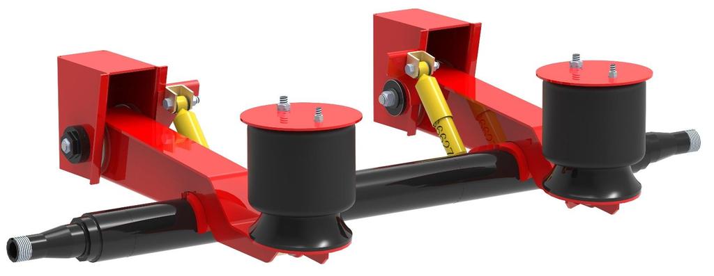
2 Roadtrack RTD Series Suspension The ROADTRACK series suspension system is a three point system available in undermount or underslung set-ups. Use of the large rolling lobe airsprings cushion your ride and allow for excellent handling. Integrated trailing beam and axle mount make this a light robust system. All Roadtrack suspension can be fitted with a lift for straight or steer applications. All components are formed and fabricated from high quality steel and robotically welded for guaranteed precision and quality. Standard features include the Eveley "Long-Life" metalastic bushing pivot connections and large hanger footprint bases. This light-weight air-ride suspension system is an excellent choice for short and long haul applications. The RTM series offers high stability, low cost, long life and easy installation. An O.E.M. standard for all applications, available in 23,000lb (10,450kg) 25,000lb (11,360kg) and 30,000lb (13,640kg) configurations. Superior Performance for the Industry Safety and durability go a long way with this Industry Standard design to give you the kind of superior performance that you've come to expect. Progressive Manufacturing Procedures Using today's "state of the art" manufacturing technologies in Robotics, Micro-electronics and Computers (CAD/CAM), an Eveley suspension has the quality and accuracy from start to finish. The direction here at Eveley is towards better design and manufacturing methods to ensure increased product life, safety and performance. Latest Design Technology 60/40 design greatly improves driver comfort while reducing fatigue and cargo damage. Low maintenance Major parts standardized Integrated beam axle seat connection Available in 12 thru 19 ride heights Wide axle seat footprint for strength and durability Drop paddle top mount design allows for higher ride heights Components that "Go the Distance" High Strength steel used in all hangers and axle connections contribute to the unmatched durability. All pivot points feature high-tech "Long-Life" bushings. All U-bolts are Grade 8 material, and are reverse mounted to allow easy torqueing to 700 ft lbs [949J]. 4/15/ pg. 2
3 TOPMOUNT SUSPENSION Topmount air-ride suspensions (axle below trailing arm configuration) use an integrated axle saddle for a positive fit. Drop paddle design allows greater road clearance at the hanger and greater up travel of the axle. Ideal for higher ride heights. STANDARD RIDE HEIGHTS AVAILABLE 12 (305mm) 13 (330mm) 14 (356mm) 15 (381mm) 16 (406mm) 17 (432mm) 18 (457mm) 19 (483mm) STANDARD WEIGHT CAPACITIES AVAILABLE 23,000lbs (10,450kg) 25,000lb(11,360kg) 30,000lb(13,640) 4/15/ pg. 3
4 ROADTRACK BEAM CENTERS TRACK LENGTH OVERALL WIDTH MAX. BEAM CENTERS AIR SPRING CENTER 71-1/2 [1816mm] 77-1/2 [1969mm] 96 [2438mm] 35 [889mm] [806mm] 102 [2591mm] 41 [1041mm] [959mm] Cross members should support the front and rear of the hanger as well as across the center of the airspring. The size and design may vary with the trailer design and are the responsibility of the trailer manufacturer 4/15/ pg. 4
5 RTD /15/ pg. 5
6 ROADTRACK RTD SERIES ORDERING INFORMATION In order to avoid confusion, our suspension kit numbering system is simple and easy to use. It contains all necessary information to identify all aspects of the kit requirements. As an example RTD25TBL-15 Means: Therefore: A model designated as RTD25TBL-15, is described as a Roadtrack suspension model RTD which has a drop paddle design and the axle is mounted under the beam in an undermount design. It has a capacity of 25,000lbs (11,360kg). An optional Twin Beam Lift has been added. The ride height is 15 (381mm). 4/15/ pg. 6
7 DETERMINING RIDE HEIGHT To determine the required ride height you must first know the distance from the bottom of the frame of the trailer to the ground when the trailer is coupled to the tractor and the trailer is at the proper level. Take this dimension and subtract half the diameter of tire. This will give you the ride height you require. Example: The distance from the ground to the bottom of the frame is 36 (914mm). The tire diameter is 40 (1016mm) = 16 Therefore your ride height will be 16 (406mm) ROADTRACK INSTALLATION INSTRUCTIONS Major components of the suspensions are factory assembled by Eveley to help reduce your assembly time and also to ensure the correct fitting of all parts. FRAME ASSEMBLY 1. Take your measurements from the center of the King Pin. Position the hanger and tack weld to the trailer frame. Hangers are handed either right of left. The shock mount is toward the center of the trailer. 2. Position and tack weld upper air spring plate in place. Note that the air spring plate is offset toward the center of the trailer (41mm). 3. Position the remaining hangers and air spring plates using the dimensions shown in the assembly drawings. 4. When all components are tacked to the frame, check for correct measurements and squareness to the frame. 5. For final welding instructions refer to Welding Specifications. 4/15/ pg. 7
8 AXLE ASSEMBLY 1. Using a table or flat surface, set up the axle assembly on axle stands or blocks, to suit, making sure that the axle T.D.C. and the horizontal axle center line are in alignment with the table or flat surface. Also check the camshaft position. 2. From the center of the axle beam, mark the required axle seat centers. 3. With the hanger and beam assemblies in the upside down position, place the trailing beam saddle on the axle. Set trailing beam centers to the marked centers on the axle. Rotate the assembly until the flat top of the hanger sits flat on the table or flat surface. 4. Check that the axle seat has complete contact on the axle beam. Clamp the saddle to the axle 5. Re-check the axle seat centers and correct if necessary. Snug up clamps. Re-check for complete contact between axle beam and saddle. 6. Once complete, clamp both hangers to the table or flat surface. Check the centers of the axle saddles and the centers of the hangers. Both measurements should be the same. 7. Tack weld each saddle to axle. See welding procedure figure 3 8. Weld axle beam to trailing beam saddles. See welding procedure. Note: Axle seat must have full contact with the axle beam before welding. Failure to do so will result in trailing beam and/or axle beam damage. See welding instruction. 9. Remove clamps. Remove assembly and reposition on bogie or main rail assembly. Center the suspension assembly, and check alignment from a point on the frame, or the king pin to each hanger center location. Adjust as required by moving complete assembly. Clamp front hangers in place. Recheck alignment. Tack weld hanger assemblies to frame. Remove clamps. 10. Position upper air bag plate on frame. Clamp and tack weld. Remove clamps. Position and tack weld front hanger bracing. Re-check all dimensions. 11. Fully weld the assembly in position. 12. With the axle set at ride height, re-check alignment. Adjust, if necessary, using the pivot alignment block on the front hanger. Once aligned, weld in place the pivot alignment blocks, both left and right on each hanger. 13. Install air springs. Check torque on all hardware. Inflate air spring and check for clearance all around the air springs. 4/15/ pg. 8
9 ALIGNMENT AND ADJUSTMENT 1. Make sure the suspension is not binding at any point and that the trailer is resting level. 2. Make sure suspension is at ride height. Commence suspension alignment by measuring from center of King Pin to the end centers of the front axle, Turn the ratchet alignment in a clockwise direction until proper alignment has been achieved. 3. Torque ratchet alignment pivot bolts to 600ft lb (813N/m) or Quick Align pivot bolts to 1000ft lb (1355(N/m) 4. Measure from front axle centers to second axle centers and so on, depending on the axle configuration. 5. Air spring bolts and nuts are torqued to 50 ft lb (68 N/m) 6. Shock bolts are torqued to 300 ft lb (407 N/m) 7. IMPORTANT - Do not lubricate any parts of the suspension. SUSPENSION INSPECTION It is recommended, that after the first 1,000 miles (1,609 km), operators should check all nuts for tightness and re-torque. Re-torqueing is essential to the guarantee and ensures proper operation. All torqueing should be periodically checked; at 10,000 miles [16,090 km], 30,000 miles [48,270 km], 50,000 miles [80450 km] etc. THIS INSPECTION IS ESSENTIAL Failure to maintain the specified torque on all nuts and bolts could result in excessive wear to the hangers, pivot bolts, bushings, airsprings, tires, and the stripping of bolt threads. A periodic check by the operator will eliminate these problems. 4/15/ pg. 9
10 EVELEY RATCHET ALIGNMENT PIVOT ASSEMBLY ADJUSTMENT PROCEDURE When performing this procedure: Suspension must be at ride height Apply sufficient pressure to the pivot nut to allow the ratchet faces to engage and disengage freely DO NOT LUBRICATE THE PIVOT BOLT OR NUT AND DO NOT USE A POWER IMPACT GUN TO TORQUE THE NUT. Use a wrench on the hexagon head of the outer ratchet block and rotate in a clockwise direction until alignment is achieved. Torque the pivot nut to 600 ft lbs DO NOT WELD any components on this assembly 4/15/ pg. 10
11 EVELEY RATCHET ALIGNMENT PIVOT ASSEMBLY RE-ALIGNMENT AND TORQUEING PROCEDURE WARNING ALWAYS USE A NEW NYLOC PIVOT BOLT NUT (RT6010) WHEN PERFORMING THIS SERVICE PROCEDURE. When performing this procedure: Suspension must be at ride height Remove the pivot bolt nut completely Install a new nut and apply sufficient pressure to the pivot nut to allow the ratchet faces to engage and disengage freely DO NOT LUBRICATE THE PIVOT BOLT OR NUT AND DO NOT USE A POWER IMPACT GUN TO TORQUE THE NUT. Use a wrench on the hexagon head of the outer ratchet block and rotate in a clockwise direction until alignment is achieved. Torque the pivot nut to 600 ft lbs DO NOT WELD any components on this assembly 4/15/ pg. 11
12 AXLE WELDING PROCEDURE Any approved Welding Rod, 7018 or the equivalent, can be used. When welding the axle to the trailing beam saddle there must be three passes on each side, alternating, side to side and front to back. The finished weld size must be a minimum 1/2"(13mm) fillet weld. Ensure that each pass is done in different directions and starting points. See figure 3. Figure 3 4/15/ pg. 12
13 The weld arc should not be started at the end of the bead. Instead, the electrode should be started away from the end of the bead and moved as shown in figure 4. The weld arc should not be finished at the end of the bead. Instead, the electrode should be finished away from the end of the bead as shown. Any craters which remain should be filled during this movement. Figure 4 4/15/ pg. 13
14 Note: Eveley International Corp. HANGER WELDING AND REINFORCING It is the responsibility of the installer to ensure that all cross members, gussets, and mounting supports, adequately support the stresses generated into the trailer frame by this installation. All fasteners used should be checked by the installer to ensure that they meet or exceed the industry standards for this application. Cross members and /or gussets must adequately support the upper air spring plate. 20,000 lbs. [9 072 kg] can be exerted through the air spring bumper. Use of maximum beam centers is strongly recommended since roll stability increases with maximum beam centers. Axles should be ordered on the understanding that an air suspension will be utilized. This will ensure the compatibility of both unit HANGER WELDING AND REINFORCING Any approved welding rod 7018 or the equivalent, can be used. A minimum 5/16 (8mm) fillet weld should be used for attachment of hangers to the frame and braces to the hangers Figure 1: Hangers on I-beam sub-frame (standard). Centers of I-beam and hangers are the same. 4/15/ pg. 14
15 Before welding, remove all oil-paint and dirt from the surface to be welded. Check that the beam centres are correct, and that the axle fits tight into the axle seat. Do not weld on the bottom of the axle. Figure 2: Hangers on I-beam sub-frame (standard). Centers of I-beam and hangers are offset to each other Reinforcing and bracing are req d 4/15/ pg. 15
16 On standard suspension designs for trailers and semi-trailers, all axle and brake moments as well as the biggest portion of the torsional stabilizing forces and a portion of the air spring weight vertical forces pass through the hangers into the vehicle frame. Therefore, the trailer frame must be strengthend as well as the hangers braced. A vertical reinforcement must be placed between the upper and lower flanges and welded to the web of the trailer frame. An angled brace should be placed between the suspension hanger face and a cross member. As shown below. Placing a brace between left and right hanger faces is not recommended EVELEY INTERNATIONAL CORP. 4/15/ pg. 16
17 PRODUCT WARRANTY This warranty shall be limited to the original purchaser from the date of sale and covers all new components manufactured by Eveley International Corp. to be free of defects in material and workmanship, for one year (parts and labour) and up to five years (parts only) when installed, assembled, and maintained in accordance with Eveley International Corp. installation and maintenance procedures, under normal use and service. The product installer is responsible for providing correct vehicle components and attachments, and providing the clearance for suspension components, axles, wheels and tires. The installer is also responsible to ensure that products supplied by Eveley International Corp. are operating within their engineering designed capabilities and capacities. The product owner is responsible for pre-operation inspection, periodic inspections, maintenance, and use of the product as specified by Eveley International Corp. This warranty is null and void if the products are subject to improper installation, modification, adjustment, unauthorized repair, damage as a result of abuse, accident, and /or negligence, and incorrect or insufficient maintenance or applications, including but not limited to, overloading product ratings or maximum vehicle weight specifications. This warranty is null and void if parts failure or system problems occur as a result of incorrect trailer or frame design. This is the responsibility of the trailer or equipment manufacturer. The responsibility under this warranty is limited to the replacement or repair of defective parts at no charge and is at the discretion of Eveley International Corp. Products to be considered for warranty are to be returned pre-paid to Eveley International Corp.and will be subject to our inspection, or the field inspection by an authorized representative of Eveley International Corp. before warranty is approved. In no event shall Eveley International Corp. be liable for any expense, loss or damage (direct, Incidental, consequential, or exemplary) including, but not limited to, towing expenses, equipment rental, downtime expenses, cargo damage, incidental expenses, or any other losses arising in connection with the sale, use or inability to use the product resulting from a warranty covered part found to be defective. Any allowance for labour costs associated with the repair or replacement of the subject component must be pre-approved in writing by Eveley International Corp. Component parts included in the Eveley International Corp. product but purchased from outside vendors are guaranteed by Eveley International Corp. to the same extent as the guarantee offered by the outside vendor to Eveley International Corp. Any Warranty implied by law, including any warranty of merchantability or fitness for a particular purpose, is limited to the expressed warranty terms provided in this warranty coverage. All wearable items are not included in this warranty. This warranty is limited to normal on highway use or written approval applications. This warranty does not cover, off road, mining, or raw wood applications. This warranty coverage is for Canada and the United States only. The use of none-genuine Eveley International Corp. replacement parts will void this warranty coverage. No other warranty is expressed or implied by Eveley International Corp. 4/15/ pg. 17
INSTALLATION AND MAINTENANCE MANUAL E6100 SERIES SPRING SUSPENSION
 INSTALLATION AND MAINTENANCE MANUAL E6100 SERIES SPRING SUSPENSION E6100 Series Spring Suspension The E6100 series suspension system is a three point system available in undermount or underslung set-ups.
INSTALLATION AND MAINTENANCE MANUAL STEER AXLES
 INSTALLATION AND MAINTENANCE MANUAL STEER AXLES INTRODUCTION The purpose of this manual is to familiarize yourself with an Eveley steer axle. Topics included will cover: Installation Adjustments Maintenance
MS2200, MS2500, and MS3000 Suspension Installation Manual ON/OFF HIGHWAY SUSPENSION SYSTEM
 MS22, MS25, and MS3 Suspension Installation Manual ON/OFF HIGHWAY SUSPENSION SYSTEM 972.547.62 8.445.736 FAX: 972.542.97 725 E. UNIVERSITY ST. McKINNEY, TEXAS 7569 www.watsonsuspensions.com Watson & Chalin
INSTALLATION AND MAINTENANCE MANUAL
 IMPORTANT This manual must accompany the trailer when delivered to the end user. INSTALLATION AND MAINTENANCE MANUAL ISS Series Suspensions 347 King Street West, Ingersoll, Ontario, Canada, N5C 3K6 Ph:
KT AIR SUSPENSION (Engineering Lit. No. KL006)
") KT AIR SUSPENSION (Engineering Lit. No. KL006) KT250 T KT300T KT250U KT300U Contents 1. Preassembly Considerations 2. KT Welding Instruction Axle Connection o Engineering LIT No: KL004 3. KT Welding Instruction
KT AIR SUSPENSION (Engineering Lit. No. KL006) KT250 T KT300T KT250U KT300U Contents 1. Preassembly Considerations 2. KT Welding Instruction Axle Connection o Engineering LIT No: KL004 3. KT Welding Instruction
Model 86/88. Suspension System. Installation and. Maintenance Instructions
 Model 86/88 Suspension System Installation and Maintenance Instructions Drawing - 213N Installation Instructions Models 86/88 m.3 Suspension System ReycoGranning Models 86 & 88 Parts List Drawing No. 2I3N
CLAYTON OFF ROAD COR JEEP GRAND CHEROKEE LONG ARM UPGRADE KIT ( WJ)
") CLAYTON OFF ROAD COR-4806011 JEEP GRAND CHEROKEE LONG ARM UPGRADE KIT (1999-2004 WJ) NOTES: This product requires general welding, fabrication and automotive mechanic skills. ing should only be done by
CLAYTON OFF ROAD COR-4806011 JEEP GRAND CHEROKEE LONG ARM UPGRADE KIT (1999-2004 WJ) NOTES: This product requires general welding, fabrication and automotive mechanic skills. ing should only be done by
Trailer Suspensions & Components
 Warranty Statement Trailer Suspensions & Components This warranty applies to suspensions manufactured by CUSH Corp that have been properly assembled and installed by the OEM. It applies to product that
Operator s Manual. Twin Rear Bagger For FastAttach Compatible Lawn Tractors
 Operator s Manual Twin Rear Bagger For FastAttach Compatible Lawn Tractors Models OEM-190-601 (for 38-inch & 42-inch decks) OEM-190-602 (for 46-inch decks) MTD PRODUCTS INC. P.O. BOX 368022 CLEVELAND,
Installation Instructions
 85-4592 rev. 08 02-18 Installation Instructions Thank you for purchasing our sway bar kit. Please read through these instructions before installation. Auxiliary Rear Anti-Sway Bar Kit for Ford F53 part
Installation Instructions
 85-5029 rev. 03 06-17 Installation Instructions Thank you for purchasing our anti-sway bar kit. Please read through these instructions before installation. Rear Anti-Sway Bar Kit for Workhorse W22, Holiday
Installation Instructions
 85-3180 rev. 07 03-14 Installation Instructions Thank you for purchasing this antisway bar kit. Please read through these instructions before installation. Front Anti-Sway Bar Kit for the Ford E350/450
Installation Instructions
 85-4341 rev. 04 10-15 Installation Instructions Thank you for purchasing this antisway bar kit. Please read through these instructions before installation. Rear Anti-Sway Bar Kit for Chevy 2500/3500/4500
Installation Instructions
 85-3700 rev. 08 05-18 Installation Instructions Thank you for purchasing this antisway bar kit. Please read through these instructions before installation. Front Anti-Sway Bar Kit for the F53 Chassis part
Installation Instructions
 85-3910 rev. 03 01-18 Installation Instructions Thank you for purchasing the antisway bar kit. Please read through these instructions before installation. Rear Anti-Sway Bar Kit for Ford F-250/F-350 part
KI AIR SUSPENSION (wide Pivot Bush)
") KI AIR SUSPENSION (wide Pivot Bush) Contents 1. Pre-assembly Considerations 2. Welding Instructions Chassis Connection 3. Tightening Instruction 4. Axle Alignment 5. Maintenance www.khitch.com.au Uncontrolled
KI AIR SUSPENSION (wide Pivot Bush) Contents 1. Pre-assembly Considerations 2. Welding Instructions Chassis Connection 3. Tightening Instruction 4. Axle Alignment 5. Maintenance www.khitch.com.au Uncontrolled
TECHNICAL PROCEDURE HENDRICKSON SUSPENSION SYSTEMS
 TECHNICAL PROCEDURE HENDRICKSON SUSPENSION SYSTEMS SUBJECT: Welding Procedures LIT NO: L64 DATE: February 2000 REVISION: E TABLE OF CONTENTS AXLE WELDING PARAMETERS HT SUSPENSIONS ONLY.....................................2
Quadratec 2 or 4 Bike Receiver Bike Racks
 Quadratec 2 or 4 Bike Receiver Bike Racks Installation Manual: Designed for Jeep Vehicles with 2 Receiver Style Hitches # 92034.1000 and # 92034.1001 PARTS LIST: Receiver Base & Main Rack System - QTY
CHEVY / GMC 1500HD / 2500HD 2WD 8 LUG 7 BASIC KIT
 85101 2000-2010 CHEVY / GMC 1500HD / 2500HD 2WD 8 LUG 7 BASIC KIT C8510-4 MAIN BOX KIT W/ HARDWARE 1) FRONT X MEMBER 1) REAR X MEMBER 2) TORSION BAR DROPS 1) LEFT BUMP STOP 1) RIGHT BUMP STOP 2) SWAY BAR
TECHNICAL PROCEDURE NON-STEERABLE SUSPENSION SYSTEMS
 TECHNICAL PROCEDURE NON-STEERABLE SUSPENSION SYSTEMS SUBJECT: Installation Instructions LIT NO: DATE: December 2003 TABLE OF CONTENTS Introduction... 2 Required Supplies... 2 Pre-Installation Checklist...
Installation Instructions
 85-3195 rev. 12 04-18 Installation Instructions Thank you for purchasing this antisway bar kit. Please read through these instructions before installation. Part #1139-117 Rear Anti-Sway Bar Kit 1½ diameter
Deere G & GP Series Snow Wing Installation
 Deere G & GP Series Snow Wing Installation Model: Serial Number: Rev. 10/13 Rylind Manufacturing, Inc. 2801 Youngfield St Suite 250 Golden, CO 80401 Offices: 303-979-3548 Fax: 303-979-4730 www.rylind.com
Installation Instructions
 85-3511 rev. 04 11-15 Installation Instructions Polyurethane Bushing Kit for Ford F-53 (Front) (replaces OE bushings and brackets) part #4139-127 1-5/8 diameter INTRODUCTION Thank you for purchasing this
MERITOR MTA SERIES TRAILER AIR SUSPENSION SYSTEMS PB-10108
 MERITOR MTA SERIES TRAILER AIR SUSPENSION SYSTEMS PB-10108 TABLE OF CONTENTS MTA23T Explode and BOM...4 Build Your OEM MTA23T Suspension...6 Build Your Own MTA23T Suspension...8 MTA25T Explode and BOM...10
IS INDEPENDENT SUSPENSION SYSTEM OWNERS MANUAL
 IS INDEPENDENT SUSPENSION SYSTEM OWNERS MANUAL * Made in U.S.A. Patent number 5899470 IS153-002 REV. 1 Description Congratulations on your purchase of the MOR/ryde IS suspension system*. The MOR/ryde IS
Installing RideSentry Suspension Axle Seats onto RideStar RHP Series Single-Axle and Sliding Tandem Trailer Air Suspension Systems
 Issued 10-07 Technical Bulletin Installing RideSentry Suspension Axle Seats onto RideStar RHP Series Single-Axle and Sliding Tandem Trailer Air Suspension Systems Issued 1 Technical 10-07 Bulletin Hazard
RAR Lightweight Trailer Suspension Owner s Manual. P.O. Box 4586 Springfield, MO
 RAR-243 Lightweight Trailer Suspension Owner s Manual www.ridewellcorp.com P.O. Box 4586 Springfield, MO 65808 417.833.4565 417.833.4560 (fax) 0711 Suspension Identification: Ridewell Suspensions are identified
Installation Instructions
 Part Numbers: ALL 5AB-XXXX DEALER/INSTALLER: (1) Provide this Manual to end user END USER: (1) Read and follow this Manual every time you use this product. PIN BOX SHOWN ASSEMBLED Equipment Required: Wrenches:
KI AIR SUSPENSION (narrow Pivot Bush)
") KI AIR SUSPENSION (narrow Pivot Bush) Contents 1. Preassembly Considerations 2. Welding Instructions Chassis Connection 3. Tightening Instruction 4. Axle Alignment 5. Maintenance www.khitch.com.au Uncontrolled
KI AIR SUSPENSION (narrow Pivot Bush) Contents 1. Preassembly Considerations 2. Welding Instructions Chassis Connection 3. Tightening Instruction 4. Axle Alignment 5. Maintenance www.khitch.com.au Uncontrolled
BOTTOM PLOW OWNERS MANUAL MOLDBOARD PLOWS
 1 BOTTOM PLOW OWNERS MANUAL MOLDBOARD PLOWS To The Owner: Read this manual before using your moldboard plow. The information presented will prepare you to do a safer, better job. Study this manual and
Please visit for the latest version of these installation instructions.
 Please visit www.blueox.com for the latest version of these installation instructions. DH2400 (Long & Standard Box) Please read these in their entirety prior to installing or operating this equipment.
Dodge Ram 1500, Quad/Reg. Cab, w/6.4ft. & 8ft. Bed, 2 & 4 WD. For updates see PRODUCT SUPPORT tab at
 Assembly, Installation, Operation and Maintenance Instructions 2009-2016 Dodge Ram 1500, Quad/Reg. Cab, w/6.4ft. & 8ft. Bed, 2 & 4 WD. Part # 30665 Dealer / Installer: Provide a copy of these Instructions
Installation Instructions
 Installation Instructions 4 Basic Suspension System 1997-2006 JEEP TJ 4WD Fabtech Motorsports 4331 Eucalyptus Ave. Chino, CA 91710 Tech Line 909-597-7800 Fax 909-597-7185 Web www.fabtechmotorsports.com
COVER PAGE CUSTOM QUICK INSTALL MOUNTING KIT NOTE!
 COVER PAGE NOTE! Prior to installing product, please visit one of our websites to assure your kit contains the most recent revision to installation instruction and verify vehicle application. www.reeseproduct.com
OWNER S GUIDE 8A DURALIFT II 13,200 LB. CAPACITY. Link Mfg. Ltd th St. N.E. Sioux Center, IA USA
 OWNER S GUIDE 8A000715 DURALIFT II 13,200 LB. CAPACITY Link Mfg. Ltd. 223 15th St. N.E. Sioux Center, IA USA 51250-2120 www.linkmfg.com QUESTIONS? CALL CUSTOMER SERVICE 1-800-222-6283 DEALER / INSTALLER:
General Medium Duty KLM C&C 2-Stage Rear Air Suspension Installation Instructions
 2686 Highway 92 - Oskaloosa, IA 52577 Phone: 641.673.0468 - Fax: 641.673.4168 www.kelderman.com General Medium Duty KLM 10745 C&C 2-Stage Rear Air Suspension Installation Instructions Class 6 & 7 Trucks
1401 / 1402 / 1403 ADJUSTABLE TRAILING ARM MOUNT BRACES INSTALLATION OF HOTCHKIS PERFORMANCE ADJUSTABLE TRAILING ARM MOUNT BRACES
 1401 / 1402 / 1403 ADJUSTABLE TRAILING ARM MOUNT BRACES 1401 78-88 GM A/G-BODY / 1402 68-72 GM A-BODY / 1403 64-67 GM A-BODY Thank you for your purchase. Please call us at (562) 907-7757 if you have any
GM 2500,3500 Nerf Bar Installation Instructions
 GM 2500,3500 Nerf Bar Installation Instructions Part # 100-7023-00 Fitment: 07-17 GM 2500/3500 Crew Cab 1) Remove Battle Armor nerf bar and hardware from box. Hardware supplied is shown below. Contains
TMC 90 SPRING SUSPENSION
 TMC 90 SPRING SUSPENSION INSTALLATION and SERVICE MANUAL TMC AUSTRALIA PTY LTD Telephone: + (61) 3 8786 3688 78 Star Crescent, P.O. Box 5028 Facsimile: + (61) 3 8786 3699 Hallam, Victoria, 3083 E-mail:
Double Scull Car Rack User s Manual
 Page 1 Double Scull Car Rack User s Manual Step 1: Attach your double scull car rack to vehicle roof racks We recommend lining up your double scull rack with the towing hooks located underneath your car
Installation Instructions
 Installation Instructions 4 Ultimate Suspension System 1997-2006 JEEP TJ 4WD Non-Rubicon Models Fabtech Motorsports 4331 Eucalyptus Ave. Chino, CA 91710 Tech Line 909-597-7800 Fax 909-597-7185 Web www.fabtechmotorsports.com
Installation Instructions **THIS RAIL MOUNTING KIT USES 11 BOLTS**
 Installation Instructions CUSTOM QUICK INSTALL MOUNTING KIT FORD SUPER DUTY Part Numbers: 50074 WARNING:Under no circumstances do we recommend exceeding the towing vehicle manufacturers recommended vehicle
STāSIS Engineering R8 Brake System
 STāSIS Engineering R8 Brake System Brake Kit Installation Instruction Application Guide SE811-B30-91-00 R8 Brake System Special Tools Required Qty Description 1 10 MM Allen Head Socket 1 M10 Triple Square
Please visit for the latest version of these installation instructions.
 Please visit www.blueox.com for the latest version of these installation instructions. 2014-2017 Ram 2500 (All beds) Please read these in their entirety prior to installing or operating this equipment.
NOTE: LIFETIME PRODUCT WARRANTY
 Carli Suspension: 422 Jenks Circle, Corona, CA 92880 Tech Support: (714) 532-2798 CS-DD30-6-03-D CS-DD30-6-10-D CS-DD30-6-10-D-12MM CS-DD30-6-12-D CS-DD30-6-12-D-12MM NOTE: Please review the product instructions
Hayes Performance Systems 5800 W. Donges Bay Rd. Mequon, WI Tel: Web:
 Hayes Performance Systems 5800 W. Donges Bay Rd. Mequon, WI 53092 Tel: 888.686.3472 Email: techsupport@hayesbicycle.com Web: www.hayescomponents.com Hayes Components Europe Dirnismaning 20 a 85748 Garching
Hollywood Racks Sport Rider Hitch Rack Instruction Manual
 Hollywood Racks Sport Rider Hitch Rack Instruction Manual Model HR1200 3 Bike, 2 rec. Model HR1210 3 Bike, 1 ¼ rec. Model HR1400-4 Bike, 2 rec. Not to be used on any trailer, fifth wheel or vehicle being
Complete Raised Rail Roof Rack System SR1098 SR1099
 Complete Raised Rail Roof Rack System SR1098 SR1099 7 kg/15 lbs xx kg xx lbs Max. 68 kg/150 lbs Instructions Max load capacity 68 kg/150 lbs Before you begin, please read the assembly instructions carefully.
JEEP WRANGLER (YJ) 4 LEAF SPRING KIT TM w/ Power Steering & TM w/ Manual Steering
 4 LEAF SPRING KIT TM w/ Power Steering & TM w/ Manual Steering") 400 W. Artesia Blvd. Fax: (310) 747-3912 Compton, CA 90220 Ph: (877) 695-7812 www.trailmastersuspension.com JEEP WRANGLER (YJ) 4 LEAF SPRING KIT 87-96 TM3540-20013 w/ Power Steering & TM3540-20023 w/ Manual
400 W. Artesia Blvd. Fax: (310) 747-3912 Compton, CA 90220 Ph: (877) 695-7812 www.trailmastersuspension.com JEEP WRANGLER (YJ) 4 LEAF SPRING KIT 87-96 TM3540-20013 w/ Power Steering & TM3540-20023 w/ Manual
Model AS-FM64 Wall Mount. Full Motion Television Wall Mount
 Model AS-FM64 Wall Mount Full Motion Television Wall Mount Getting Started Introduction Congratulations on the purchase of your new Audio Solutions AS-FM64 Television Wall Mount. For maximum benefit, please
JEEP WRANGLER 2 & 4 DOOR (JK) 2.5 SPACER KIT KIT# TM /TM
 2.5 SPACER KIT KIT# TM /TM") 400 W. Artesia Blvd. Fax: (310) 747-3912 Compton, CA 90220 Ph: (877) 695-7812 www.trailmastersuspension.com JEEP WRANGLER 2 & 4 DOOR (JK) 2.5 SPACER KIT 07-13 KIT# TM3325-40010/TM3325-40013 Installation
400 W. Artesia Blvd. Fax: (310) 747-3912 Compton, CA 90220 Ph: (877) 695-7812 www.trailmastersuspension.com JEEP WRANGLER 2 & 4 DOOR (JK) 2.5 SPACER KIT 07-13 KIT# TM3325-40010/TM3325-40013 Installation
580RK SERVICE GUIDELINES For coupling models: 580 & 580J
 580 Coupling THE FIRST NAME IN QUALITY COUPLINGS 580RK SERVICE GUIDELINES For coupling models: 580 & 580J BEFORE GETTING STARTED: This procedure should only be performed by a qualified mechanic. Measure
PIVOTING TANDEM CARRIER 558P
 K PIVOTING TANDEM CARRIER 558P PARTS INCLUDED C A D I B D I G E J F part description part number qty. A front beam 1 B tail beam 1 C detent pin and tether 8535259 2 D wheel strap assembly 8535260 2 E handlebar
1250 LB. CAPACITY MECHANICAL WHEEL DOLLY
 1250 LB. CAPACITY MECHANICAL WHEEL DOLLY 67287 SET-UP AND OPERATING INSTRUCTIONS Visit our website at: http://www.harborfreight.com Read this material before using this product. Failure to do so can result
AWE Track Edition Exhaust System Ford Focus ST 2.0T. AWE website here
 Thank you for purchasing the AWE Track Edition Exhaust System for the 2013+ Ford Focus ST 2.0T. For up-to-the-minute fitment information, be sure to visit the Ford Focus section of the AWE website. As
INSTALLATION INSTRUCTIONS QA1 P/N x400, x500, x600, x400, x500, x F100 Front Coil-over Suspension System
 INSTALLATION INSTRUCTIONS QA1 P/N 52620-x400, 52620-x500, 52620-x600, 52621-x400, 52621-x500, 52621-x600 65-72 F100 Front Coil-over Suspension System TOOLS AND SUPPLIES REQUIRED Floor Jack Two (2) Jack
Model T2642 Wall Mount. Television Wall Mount with Tilt Option
 Model T2642 Wall Mount Television Wall Mount with Tilt Option Getting Started Introduction Congratulations on the purchase of your new Audio Solutions T2642 Television Wall Mount. For maximum benefit,
CLAYTON OFF ROAD COR JEEP GRAND CHEROKEE PRO SERIES 3 LINK FRONT LONG ARM UPGRADE KIT ( , ZJ)
") CLAYTON OFF ROAD COR-4804331 JEEP GRAND CHEROKEE PRO SERIES 3 LINK FRONT LONG ARM UPGRADE KIT (1993-1995, ZJ) NOTES: This product requires general welding, fabrication and automotive mechanic skills. Welding
CLAYTON OFF ROAD COR-4804331 JEEP GRAND CHEROKEE PRO SERIES 3 LINK FRONT LONG ARM UPGRADE KIT (1993-1995, ZJ) NOTES: This product requires general welding, fabrication and automotive mechanic skills. Welding
VersaHitch Bike Rack
 VersaHitch Bike Rack Installation Manual: for Jeep Wrangler with VersaHitch # 92034.3000 PARTS LIST: Receiver Bases - QTY 2 Main Rack System - QTY 1 Installation Hardware - SEE PAGE 3 REQUIRED TOOLS: Safety
CLAYTON OFF ROAD COR JEEP GRAND CHEROKEE PRO SERIES REAR LONG ARM UPGRADE KIT ( , ZJ)
") CLAYTON OFF ROAD COR-4804351 JEEP GRAND CHEROKEE PRO SERIES REAR LONG ARM UPGRADE KIT (1993-1998, ZJ) NOTES: This product requires general welding, fabrication and automotive mechanic skills. Welding should
CLAYTON OFF ROAD COR-4804351 JEEP GRAND CHEROKEE PRO SERIES REAR LONG ARM UPGRADE KIT (1993-1998, ZJ) NOTES: This product requires general welding, fabrication and automotive mechanic skills. Welding should
JEEP CHEROKEE (XJ) 3 SPRING KIT TM w/ Rear Add-A-Leaf & TM w/ Rear Leaf Spring
 3 SPRING KIT TM w/ Rear Add-A-Leaf & TM w/ Rear Leaf Spring") 400 W. Artesia Blvd. Fax: (310) 747-3912 Compton, CA 90220 Ph: (877) 695-7812 www.trailmastersuspension.com JEEP CHEROKEE (XJ) 3 SPRING KIT 84-01 TM3730-40013 w/ Rear Add-A-Leaf & TM3730-40023 w/ Rear
400 W. Artesia Blvd. Fax: (310) 747-3912 Compton, CA 90220 Ph: (877) 695-7812 www.trailmastersuspension.com JEEP CHEROKEE (XJ) 3 SPRING KIT 84-01 TM3730-40013 w/ Rear Add-A-Leaf & TM3730-40023 w/ Rear
Independent Suspension System Owner s Manual
 Independent Suspension System Owner s Manual Independent Suspension System CONTENTS Introduction...2 Parts Listing & Rubber Shear Spring Defelction...3 Maintenance Checks & Trouble Shooting...4 & 5 Warranty...6
Hollywood Racks Assembly & installation instructions for models:
 Hollywood Racks Assembly & installation instructions for models: HR1400Y (4 bike), HR1450Y (2 bike), HR1475Y, 1450Y-E & 1455Y-E (E bikes) For use on 2 hitches only. Do not use a 1 ¼ -2 hitch adapter. Maximum
INSTALLATION INSTRUCTIONS FOR 2016 TOYOTA TACOMA 4 X 4 AND PRERUNNER FRONT LIGHT BAR MOUNT PART NUMBER 20016
 INSTALLATION INSTRUCTIONS FOR 2016 TOYOTA TACOMA 4 X 4 AND PRERUNNER FRONT LIGHT BAR MOUNT PART NUMBER 20016 WARNING!!! READ AND UNDERSTAND ALL INSTRUCTIONS BEFORE PROCEEDING. MAKE SURE THAT YOU HAVE ALL
INSTALLATION MANUAL FOR ROCK KRAWLER SUSPENSION, INC. WJ SHORT ARM SYSTEMS
 INSTALLATION MANUAL FOR ROCK KRAWLER SUSPENSION, INC. WJ SHORT ARM SYSTEMS FIRST EDITION 8/24/09 Dear customer: Thank you for purchasing the best system on the market for your Jeep Vehicle. We are sure
Instruction Manual 30K - Fifth Wheel Hitch Part Number 30054
 You can take it with you. ELKHART, IN., OAKVILLE, ONT. Instruction Manual 30K - Fifth Wheel Hitch Part Number 30054 DEALER/INSTALLER: (1) Provide this Manual to end user. (2) Physically demonstrate hitching
DODGE / RAM 1500 *** DO NOT EXCEED VEHICLE MANUFACTURER'S RECOMENDED TOWING CAPACITY ***
 6444 DODGE / RAM 500 6/8/207 OF 5 *** DO NOT EXCEED MANUFACTURER'S RECOMENDED TOWING CAPACITY *** ITEM QTY PART NUMBER 0 /2-3 x 2" 2 4 /2-3 x 3/4, GR8 3 4 CM-SP2 4 2 CM-SP6 5 4 HFN 23, GR8 6 2 CM-SP4 7
IMPORTANT SAFETY INFORMATION
 Specifications Tricycle Height 26 Front Wheel 5/8 Axle Diameter, 13 Pneumatic Knobby Tire Back Wheels 5/8 Axle Diameter, 10 Pneumatic Knobby Tire Age Range 5 and up Weight Capacity 150 lb. IMPORTANT SAFETY
TABLE OF CONTENTS TRAILER INFORMATION... 3 COUPLING TO THE TOW VEHICLE... 4 LOADING THE TRAILER... 9 CHECKING THE TRAILER... 10
 TABLE OF CONTENTS TRAILER INFORMATION... 3 COUPLING TO THE TOW VEHICLE... 4 COUPLING AND UNCOUPLING THE TRAILER FROM THE TOW VEHICLE... 4 BALL-HITCH COUPLER... 4 INSTRUCTIONS ON COUPLING TO THE TOWING
INSTALLATION INSTRUCTIONS FOR MOUNTING HARDWARE KIT F-105K2.5
 MY SAFE T PLUS UNIT INSTALLATION INSTRUCTIONS FOR MOUNTING HARDWARE KIT F-105K2.5 This kit supports installation of SAFE T PLUS : MODEL # 41-140 (RED) MODEL # 41-180 (WHITE) MODEL #41-230 (BLUE) KEEP INSTRUCTIONS
Grapple Kit Install & Grapple Bucket Manual
 Grapple Kit Install & Grapple Bucket Manual Model # Serial # Rev. 10/13 Rylind Manufacturing, Inc. 2801 Youngfield St Suite 250 Golden, CO 80401 Business/Sales Offices: 303-979-3548 Manufacturing Plant:
Instruction Sheet. SFR Series. Swing Frame rack
 Instruction Sheet SFR Series Swing Frame rack THANK YOU Thank you for purchasing the SFR Series Swing Frame Rack. Please read these instructions thoroughly before installing/assembling this product. PRODUCT
Installation Instructions
 Equipment Required: Installation Instructions Fastener Kit: F Wrenches: 8mm, 13mm, 3/4, 15/16 Drill Bits: 1/4 Other Tools: Drill, Reciprocating Saw, File WARNING: Under no circumstances do we recommend
Installation Instructions
 Equipment Required: Fastener Kit: F Wrenches: 3/4, 15/16 Drill Bits: 1/4 Other Tools: Drill Short & Long Bed All Megacabs 9464/9474 HIDE-A-GOOSE HITCH INSTALLATION WARNING: Under no circumstances do we
Trailer Suspension Series Installation Instructions. Advancing the Practical Application of Suspension Technology
 900-9700 Trailer Suspension Series Installation Instructions Advancing the Practical Application of Suspension Technology Springfield, MO n (800) -882 n (17) 82-012 Fax (17) 82-217 n www.hutchensindustries.com
SUPERLIFT STEERING STABILIZER KIT INSTALLATION INSTRUCTIONS
 FORM#92665.01-050614 PRINTED IN U.S.A. PAGE 1 OF 5 SUPERLIFT STEERING STABILIZER KIT INSTALLATION INSTRUCTIONS INTRODUCTION Installation requires a professional mechanic. Prior to beginning, inspect the
51201 INSTALLATION INSTRUCTIONS
 7929 Lincoln Ave. Riverside, CA 92504 Phone: 951.689.ICON Fax: 951.689.1016 PART # 51201 51201 INSTALLATION INSTRUCTIONS DESCRIPTION 07-UP TUNDRA MULTI-RATE RXT LEAF SPRING KIT 1-22-2019 REV.B COMPONENTS
Installation Instructions
 85-3414 rev. 02 11-09 Installation Instructions Thank you for purchasing this anti-sway bar kit. Please read through these instructions before installation. Rear Anti-Sway Bar Kit for the Monaco Diplomat
Installation Instructions
 85-4209 rev. 05 11-18 Installation Instructions Thank you for purchasing this anti-sway bar kit. Please read through these instructions before installation. Factory Replacement Anti-Sway Bar Kit part #1129-135
JEEP CHEROKEE (XJ) 3 SPRING KIT w/ Control Arms TM w/ Rear Add-A-Leaf & TM w/ Rear Leaf Spring
 3 SPRING KIT w/ Control Arms TM w/ Rear Add-A-Leaf & TM w/ Rear Leaf Spring") 400 W. Artesia Blvd. Fax: (310) 747-3912 Compton, CA 90220 Ph: (877) 695-7812 www.trailmastersuspension.com JEEP CHEROKEE (XJ) 3 SPRING KIT w/ Control Arms 84-01 TM3730-40033 w/ Rear Add-A-Leaf & TM3730-40043
400 W. Artesia Blvd. Fax: (310) 747-3912 Compton, CA 90220 Ph: (877) 695-7812 www.trailmastersuspension.com JEEP CHEROKEE (XJ) 3 SPRING KIT w/ Control Arms 84-01 TM3730-40033 w/ Rear Add-A-Leaf & TM3730-40043
HSIV PLOW OPERATOR S MANUAL
 PLOW RWF INDUSTRIES 873 Devonshire Ave., Woodstock, Ontario N4S 8Z4 Tel: (519) 421-0036 Toll Free: 1-800-263-1060 Fax: (519) 421-0028 Email: parts@rwfbron.com JANUARY 2015 THE INFORMATION CONTAINED IN
Air Lift. Kit Honda Prelude ( ) PERFORMANCE INSTALLATION GUIDE
 PERFORMANCE INSTALLATION GUIDE") Air Lift PERFORMANCE Kit 75532 Honda Prelude (1992-2001) Cover illustration may not depict actual kit. MN-542 (06708) ECR 6206 INSTALLATION GUIDE For maximum effectiveness and safety, please read these
Air Lift PERFORMANCE Kit 75532 Honda Prelude (1992-2001) Cover illustration may not depict actual kit. MN-542 (06708) ECR 6206 INSTALLATION GUIDE For maximum effectiveness and safety, please read these
Technical Support Line: (952) Hanover Ave. Lakeville, MN
 Hanover Ave. Lakeville, MN") Technical Support Line: (952) 985-5675 Email: Sales@QA1.net 21730 Hanover Ave. Lakeville, MN 55044 www.qa1.net INSTALLATION INSTRUCTIONS QA1 1967-1979 Mopar A-Body Rear 6 link Conversion System QA1 p/n
Technical Support Line: (952) 985-5675 Email: Sales@QA1.net 21730 Hanover Ave. Lakeville, MN 55044 www.qa1.net INSTALLATION INSTRUCTIONS QA1 1967-1979 Mopar A-Body Rear 6 link Conversion System QA1 p/n
HIGH DUMP ROLL-OUT BUCKET
 HIGH DUMP ROLL-OUT BUCKET Model # Serial # Rev. 01/14 Rylind Manufacturing, Inc. 2801 Youngfield St Suite 250 Golden, CO 80401 Business/Sales Offices: 303-979-3548 Manufacturing Plant: 970-522-2859 www.rylind.com
Rear Weight Kit M060
 Operator s Manual Rear Weight Kit 490-900-M060 WARNING READ AND FOLLOW ALL SAFETY RULES AND INSTRUCTIONS IN THIS MANUAL BEFORE ATTEMPTING TO OPERATE THIS MACHINE. FAILURE TO COMPLY WITH THESE INSTRUCTIONS
" CHEVY / GMC WD BASIC KIT
 84302 2007-2013 6" CHEVY / GMC 1500 4WD BASIC KIT 100% Bolt On 6 Spindle Kit Front Differential Is Dropped A Full 6 To Maintain Proper CV Axle Angles Impact Struts To Distribute Front Suspension Impact
Installation Instructions
 Safe Operation Practices Set-Up Operation Maintenance Service Troubleshooting Warranty Installation Instructions RZT & Z-Force Light Kit Model 19B70032100 WARNING READ AND FOLLOW ALL SAFETY RULES AND INSTRUCTIONS
OWNER'S MANUAL L A W N R O L L E R PRT-481S BH. Safety Assembly Operation Repair Parts Maintenance. Visit us on the web!
 OWNER'S MANUAL L A W N R O L L E R ROLLER MODEL: PRC- BH PRT- BH PRT-S BH PRT-S BH Safety Assembly Operation Repair Parts Maintenance Recommended for use with Riding Mowers, Lawn or Garden Tractors, and
Installation Instructions
 Installation Instructions CUSTOM QUICK INSTALL MOUNTING KIT 2011 & UP Ford Super Duty F-250/F-350/F-50 2011 & UP Part Number: 50073 WARNING: Under no circumstances do we recommend exceeding the towing
Thank you for purchasing the AWE SwitchPath Exhaust System for the Audi B9 S4.
 Thank you for purchasing the AWE SwitchPath Exhaust System for the 2017+ Audi B9 S4. Switchpath Exhaust Parts: 1 Driver downpipe upper section (part A10) 1 Driver downpipe lower section (part A12) 1 Passenger
Model AS-RC3260 TV Cart. Rolling Cart for Audio Mount System & Flat Panel TVs
 Model AS-RC3260 TV Cart Rolling Cart for Audio Mount System & Flat Panel TVs GETTING STARTED Introduction Congratulations on the purchase of your new Helios AS-RC3260 Rolling Cart. For maximum benefit,
AWE Touring Edition Exhaust and Performance Mid Pipe System BMW M240i Coupé.
 Thank you for purchasing the AWE Touring Edition Exhaust and Performance Mid Pipe System for your 2017+ BMW M240i Coupé. For up to the minute fitment information, be sure to visit the BMW M240i section
stroller kit Burley Stroller Kit Owner s Instruction and Safety Manual For D Lite, Solo, Encore, Cub, Honeybee, and Tailwagon
 stroller kit Burley Stroller Kit Owner s Instruction and Safety Manual For D Lite, Solo, Encore, Cub, Honeybee, and Tailwagon Congratulations! By purchasing the Burley Stroller Kit, you ve increased the
JK HD Skid Plate for Rear Falcon Shocks
 1 JK HD Skid Plate for Rear Falcon Shocks Kit # 36-07-01-300 Important Notes: Prior to beginning this or any installation read these instructions to familiarize yourself with the required steps and evaluate
Installation / Owners Manual
 DEALER/INSTALLER: (1) Provide this Manual to end user END USER: Part Number: 94621 94622* *Packaged for Individual sale. (1) Read and follow this Manual for Reese Installation. (2) Save this Manual for
RVT SERIES HEAVY DUTY TRIPPING SNOW PLOW
 RVT SERIES HEAVY DUTY TRIPPING SNOW PLOW Model: Serial Number: Rev. 10/13 Rylind Manufacturing, Inc. 2801 Youngfield St Suite 250 Golden, CO 80401 Main Offices: 303-979-3548 Manufacturing Plant: 970-522-2859
WARNING!!! READ AND UNDERSTAND ALL INSTRUCTIONS BEFORE PROCEEDING. MAKE SURE THAT YOU HAVE ALL TOOLS AND PARTS BEFORE BEGINNING THE INSTALLATION.
 INSTALLATION INSTRUCTIONS FOR 2007-2015 JEEP JK 3 SUSPENSION LIFT SYSTEM PART NUMBER 587 WARNING!!! READ AND UNDERSTAND ALL INSTRUCTIONS BEFORE PROCEEDING. MAKE SURE THAT YOU HAVE ALL TOOLS AND PARTS BEFORE
Installation Instructions
 Equipment Required: Fastener Kit: F Wrenches: 15/16, 10 mm Drill Bits: 1/4 Other Tools: Drill, Reciprocating Saw 9464/9474 HIDE-A-GOOSE HITCH INSTALLATION All Fasteners Typical, Both Sides WARNING: Under
31033 INSTALLATION INSTRUCTIONS
 10 INSTALLATION INSTRUCTIONS Safety glasses should be worn at all times while installing this product. YEARS: 011-PRESENT MAKE: JEEP / DODGE MODEL: GRAND CHEROKEE / DURANGO STYLE: SUV WARNING: NEVER EXCEED
Fontaine Custom Duty Instructions
 Fontaine Custom Duty Instructions Fifth Wheel Installation instructions Pre-service procedures Operating instructions Inspection & maintenance procedures Warranty FOR YOUR SAFETY USE ONLY GENUINE FONTAINE