Speed Reducers and Gearmotors
|
|
|
- Georgia Long
- 6 years ago
- Views:
Transcription

1 ofc BEVEL BUDDYBOX Speed Reducers and earmotors CATALO


2 Bevel Buddybox Rugged Spiral Bevel Output Modular Cyclo Input Compact Size Two-Year Warranty Eccentric Cam and Roller Assembly Housing Ring ear Housing Cyclo Discs Integral earmotor Slow Speed Shaft Rollers Slow Speed Shaft Pins Ring ear Pins and Rollers Use our online product configurator to build a to fit your application. See inside back cover for further details. Configure your today at To request a catalog, or for more information on any of our high quality products, please visit our website:


3 Speed Reducers and earmotors Table of Contents 1. eneral Information 2. Speed Reducers How to Select Configure a Model Number (Nomenclature) AMA Load Classifications Selection Tables Single Reduction Horizontal Mounting Vertical Mounting Double Reduction Dimensions earmotors How to Select Configure a Model Number (Nomenclature) AMA Load Classifications Selection Tables Horizontal Mounting Inverter Duty Dimensions Options 5. Appendices Special Load uidelines Lubrication Motor Data Standard Wiring Thermal Duty Brakemotor Characteristics Warranty


4 Bevel Buddybox Flexible configurations Shaft Options: Keyed Hollow Shrink Disc Mounting Options: Flange U Face 100% Hardened Steel Internal Components Provide long life, smooth operation and superior strength Unique Splined Connection Ensures more durable and dependable power transmission than typical keyed connections Cyclo or Planetary Input Provides high overload capacity and exceptional reliability Compact Housing New smooth housing design is optimized for small mounting spaces Choice of Input Integral motor, C-Face and Quill models available Tapered Bearings Resist axial and radial loads simultaneously Double Element Output Seals Prevent leaks and exclude contaminants More Compact, Space-Saving Design Than Typical Right-Angle earboxes Simple, Single Reservoir Oil Lubrication 1.2 eneral Information


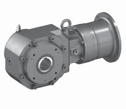
5 Right Angle Spiral Bevel earbox with Cyclo Reducer Input Product Description The Cyclo Bevel Buddy Box 5 () built by Sumitomo is a versatile, high efficiency right angle unit that shares many of the features of the larger, robust Cyclo BBB4. The has been carefully constructed to take advantage of the inherent design advantages of the Cyclo and planetary inputs. In addition, because the design has been optimized for shaft mounted applications, the exterior dimensions have been minimized, without compromising the ability to transmit torque. The result is an extremely compact, efficient and reliable unit in a very power-dense package. The is yet another example of a unique combination of features that produces a highly reliable, long-lived and efficient gearbox. Like the BBB4, the all-steel internal construction, in conjunction with the Cyclo or planetary gear inputs, results in a gearbox that is truly dependable. Features & Benefits High performance steel bevel gear sets ~ Deliver high efficiency and consistent quality Double element output seals ~ Four seal lips on every unit virtually eliminates the possibility of leaks Robust Input Sections ~ Cyclo and planetary inputs ensure year after year dependability Two year warranty ~ Not limited by hours of operation or duty cycles AMA Ratings and Selection Methods ~ Conservative ratings, based on successful industry experience Numerous s ~ Buy exactly the ratio needed Not thermally limited ~ Runs cooler and lasts longer Specifications Summary s: 11:1 to 26,492:1 and greater Torque Capacity: 45,450 in. lbs. (5,140 N m) HP: 1/8 to 75 (0.1 to 55 kw) Mounting: Hollow Shaft, Flange, Face Options: Integral Motor, C-Face, Quill, Shrink Disc and Shovel Base Motor Standards: NEMA, IEC, JIS, UL, CSA, CE Two Output Styles Easy on and off shrink disc option Standard metric sizes Shrink Disc Simple, economical keyed hollow bore Inch or metric sizes readily available Keyed Hollow Bore Cyclo Quality and Reliability, Right Angle Design High performance steel input components deliver up to 94% efficiency eneral Information 1.3
6 Product Range (Standard Motor and Reducer Combinations) Single Reduction s Output RPM Motor Power Combinations with 1750 RPM motor Hz Hz /4 (0.2) 1/3 (0.25) 1/2 (0.4) 3/4 (0.55) 1 (0.75) 1.5 (1.1) 2 (1.5) 3 (2.2) 5 (3.7) 7.5 (5.5) 10 (7.5) 15 (11) 20 (15) 25 (18.5) 30 (22) 40 (30) 50 (37) 60 (45) 75 (55) Double Reduction s Combinations with 1750 RPM motor Output RPM Motor Power Hz Hz /8 (0.1) 1/4 (0.2) 1/3 (0.25) 1/2 (0.4) 3/4 (0.55) 1 (0.75) 1.5 (1.1) 2 (1.5) 3 (2.2) 1.4 eneral Information
7 FAQs How do I select a speed reducer or gearmotor? Selection is based on the actual horsepower and/or torque requirements at the output shaft. The speed reducer has particularly high efficiencies over a wide range of reduction ratios, which frequently permits the use of reduced input power requirements (smaller HP or kwmotor) without sacrificing output shaft torque. The selection procedures in this catalog will guide you in choosing the most efficient reducer for your application. What information do I need to get started in the selection process? To select the proper reducer for your application, you will need to know: Application: type of driven machine Hours of operation per day Motor horsepower (HP or kw) and speed (RPM) Mounting position Environmental conditions Ambient temperature range If there are any special environmental factors or operation requirements, they must also be noted. This information will be important in determining the Service Factor of your application. What is the difference between BBB4 and BBB5? The BBB5 is optimized for a minimal space envelope and shaft mounted applications. The BBB4 is more rugged by virtue of its stronger ductile iron housing, which has multiple mounting surfaces and is offered in numerous variants, including foot mounts and solid shafts. What are Service Factors and how are they used? In general, reducers and gearmotors are rated for the specific conditions and operating requirements of the application by the use of AMA-defined Service Factors. There are three AMA load classifications for reducers: uniform (U), moderate shock (M) and heavy shock (H) (page 2.6) and three AMA load classifications for gearmotors: I, II and III (pages ). The Service Factors are used in the product selection process to adjust for the specific conditions and operating requirements of your application. What do I do if my application has particularly severe operating conditions? The standard ratings for are based on 10-hour daily service under conditions of uniform loads (equivalent to AMA service factor 1.0). By following the product selection process, you will determine and apply the Service Factors to compensate for the severe operating conditions. How can I be sure that the reducer can withstand periodic excessive overloads? Speed Reducers can provide solutions with extraordinary shock load capabilities. For applications with high shock loads, consult a Sumitomo Applications Engineer What are the standard input speeds? In general terms, the speeds are 1750 and 1450 RPM. The selection tables in this catalog are based on 1750 and 1450 RPM. When non-standard input speeds are used, the horsepower and torque ratings also vary. What thermal capacity limitations does the have? The Cyclo speed reducer, by virtue of its smooth, almost frictionless operation (unlike traditional helical gears), has a thermal rating that far exceeds its mechanical capacity and all but eliminates the conventional limitations due to heat. What are the advantages of a shrink disc? The shrink disc provides for easy mounting and removal to and from the shaft of the driven machine. Because it requires no keyway, the shaft isn t weakened and maximum torque is transmitted. What kind of torque arm do I specify? At what position should I mount it? The standard torque arm assembly supplied is a Flange Mount (Banjo) type as shown on page 4.3. The torque arm should be mounted at 90 degrees to a line from the point of attachment to the reducer and the center of the output bore with up to 30 degrees plus or minus variance. A bracket type torque arm is also offered as a non-stock option. eneral Information 1.5
8 Standard Specifications Standard Specifications Standard Specifications with Built-In Brake 3-Phase Capacity Range: 1/8 ~ 75 HP (0.1 ~ 55 kw), 4P 1/8 ~ 40 HP (0.1 kw ~ 30 kw), 4P: FB Brake Integral Motor 50 ~ 75 HP (37 kw ~ 55 kw), 4P: ESB Brake Enclosure: Totally enclosed fan cooled type Totally enclosed fan cooled type (1/8, (0.1 kw), 4P Totally enclosed non ventilated) (1/8, 0.1 kw, 4P Totally enclosed non ventilated) Power Supply: 230/460 Volts, 60 Hz 230/460 Volts, 60 Hz 575 Volts, 60 Hz 575 Volts, 60 Hz Insulation: Class F Class F Time Rating Continuous Continuous Reducer Reduction: Combination of Cyclo input and right angle spiral bevel gear output. Lubrication: Seals: Cyclo portion is oil lubricated; Bevel portion is oil lubricated. Nitrile material, dual lipped. Material: Rugged cast iron housings in unit sizes 5A through 5C, and die cast aluminum for unit size 5Z. Paint Color: Blue, Munsell color number 6.5PB 3.6/8.2 Bearings: Tapered roller bearings on geared output of unit sizes 5A through 5C and deep groove ball bearings in unit size 5Z. Ball bearings on Cyclo input. Ambient Installation Location: Indoors (Minimal dust and humidity) Conditions Ambient Temperature: 14 ~104 F (-10º ~ 40º C) Ambient Humidity: Under 85% Elevation: Atmosphere: Under 3,281 ft. (1000 meters) Well ventilated location, free of corrosive gases, explosive gases, vapors and dust. Shaft Rotation On single reduction speed reducers, ratios 11 through 417, the slow speed shaft rotates in a reverse direction to that of the high speed shaft. On double reduction units, ratios 357 through 26,492, both the high speed and the slow speed shaft rotate in the same direction. Input Speeds In general terms, the standard input speeds of single reduction units are 1750 and 1450 RPM. When non-standard input speeds are used, the power and torque ratings will also vary. Thermal Capacity The speed reducer s smooth, almost frictionless operation all but eliminates the conventional limitations due to heat. In all sizes, speed reducers have thermal ratings that exceed their mechanical capacity. 1.6 eneral Information


9 Mounting Positions Note: Y1 position eyebolt provided as standard for all positions. Consult factory for eyebolts shown for positions Y2-Y6. Y1 Y2 Y3 Y4 Y5 Y6 eneral Information 1.7
10 Optional Nominal and Exact s Nominal Exact Nominal Exact Nominal Exact Nominal Exact Nominal Exact Nominal Exact Nominal Exact Nominal Exact Nominal Exact Nominal Exact Nominal Exact Nominal Exact Nominal Exact Nominal Exact Single Reduction Overall Input Overall Output 3.2 Input Double Reduction Overall Input Overall Output Input (11 x 11) (21 x 6) (15 x 8) (17 x 8) (21 x 6) (13 x 11) (17 x 8) (25 x 6) (15 x 11) (21 x 8) (13 x 13) (29 x 6) (21 x 8) (17 x 11) Overall Input Overall Output Input (29 x 6) (15 x 13) (25 x 8) (17 x 11) (35 x 6) (17 x 13) (15 x 15) (21 x 11) (17 x 13) (15 x 15) (29 x 8) (17 x 15) (43 x 6) (21 x 13) Overall Input Overall Output Input (17 x 15) (35 x 8) (43 x 6) (17 x 17) (25 x 11) (35 x 8) (21 x 15) (17 x 17) (29 x 11) (25 x 13) (51 x 6) (21 x 15) (25 x 13) (21 x 17) Overall Input Overall Output Input (25 x 15) (43 x 8) (29 x 13) (35 x 11) (59 x 6) (21 x 17) (51 x 8) (25 x 15) (35 x 11) (25 x 17) (29 x 15) (21 x 21) (51 x 8) (35 x 13) Overall Input Overall Output Input (25 x 17) (59 x 8) (43 x 11) (29 x 15) (21 x 21) (29 x 17) (35 x 13) (59 x 8) (87 x 6) (35 x 15) (29 x 17) (43 x 13) (51 x 11) (71 x 8) Overall Input Overall Output Input (87 x 6) (35 x 15) (35 x 17) (29 x 21) (51 x 11) (71 x 8) (25 x 25) (43 x 15) (59 x 11) (35 x 17) (29 x 21) (25 x 25) (87 x 8) (43 x 15) Overall Input Overall Output Input (29 x 25) (43 x 17) (35 x 21) (87 x 8) (51 x 15) (59 x 13) (71 x 11) (29 x 25) (35 x 21) (51 x 15) (59 x 13) (29 x 29) (71 x 11) (51 x 17) Overall Input Overall Output Input (35 x 25) (59 x 15) (43 x 21) (71 x 13) (51 x 17) (87 x 11) (35 x 25) (59 x 15) (43 x 21) (59 x 17) (71 x 13) (35 x 29) (87 x 11) (71 x 15) Overall Input Overall Output Input (51 x 21) (43 x 25) (35 x 29) (87 x 13) (71 x 15) (51 x 21) (43 x 25) (71 x 17) (35 x 35) (59 x 21) (43 x 29) (51 x 25) (87 x 15) (71 x 17) Overall Input Overall Output Input (35 x 35) (59 x 21) (51 x 25) (87 x 15) (59 x 25) (71 x 21) (43 x 35) (59 x 25) (71 x 21) (43 x 35) (59 x 29) (71 x 25) (51 x 35) (87 x 21) Overall Input Overall Output Input (43 x 43) (59 x 29) (71 x 25) (51 x 35) (87 x 21) (71 x 29) (59 x 35) (87 x 25) (51 x 43) (71 x 29) (87 x 25) (51 x 43) (71 x 35) (87 x 29) Overall Input Overall Output Input (59 x 43) (51 x 51) (71 x 35) (87 x 29) (51 x 51) (59 x 51) (87 x 35) (71 x 43) (59 x 51) (71 x 43) (59 x 59) (71 x 51) (87 x 43) Overall Input Overall Output Input (71 x 51) (87 x 43) (71 x 59) (87 x 51) (71 x 59) (71 x 71) (87 x 59) (71 x 71) (87 x 71) (87 x 87) 1.8 eneral Information All ratios listed include double reduction Cyclo inputs. Consult factory for available frame sizes and ratings.

11 5 5.1
12 Special Load uidelines Input Shaft Overhung Load Reducer Allowable Input Shaft Overhung Load The radial load acting on the high speed shaft may be calculated with the following formula: Pr Pro Lf Cf Sf LEEND Pr = Actual Radial Load (lbs, N) Pro = Allowable radial load (lbs, N) (Table 5.4) Lf = Load Location factor (Table 5.3) Cf = Coupling factor (Table 5.1) Sf = Service factor (Table 5.2) Figure 5.1: Input Shaft Load Location Factor (Lf) Centerline of Load Pr Table 5.1: Load Connection Factor Type of Connection Cf eneral Purpose Chain 1.0 Machined ear, Pinion or Synchronous Belt 1.25 V-Belt 1.5 Table 5.2: Service Factor Flat Belt 2.5 XV Table 5.3: Input Shaft Load Location Factor (Lf) Shock Factor Sf No Shock 1.0 Moderate Shock 1.5 Heavy Shock 2.0 Model 5Z10DA, 5Z12DA, 5A12DA, 5B12DA, 5B14DA, 5C14DA 5Z12DB, 5A12DB, 5B12DB, 5B14DB, 5C14DB, 5C16DA, 5C17DA 5Z100, 5Z105, 5C14DC, 5C16DB, 5C17DB 0.20 (5) 0.39 (10) 0.59 (15) 0.79 (20) 0.98 (25) 1.18 (30) 1.38 (35) L inch (mm) 1.57 (40) (45) 1.97 (50) 2.36 (60) 2.76 (70) 3.54 (90) 3.54 (90) 3.94 (100) 5Z110, 5Z115, 5A110, 5A115 5Z120, 5Z125, 5A120, 5A125, 5B120, 5B125, 5C17DC 5A140, 5A145, 5B140, 5B145, 5C140, 5C145 5B160, 5B165, 5C160, 5C C170, 5C
13 Special Load uidelines Input Shaft Overhung Load continued Table 5.4: Input Shaft Overhung Load Capacity Pro (Lf, Cf, Sf = 1) Model 5Z10DA, 5Z12DA, 5A12DA, 5B12DA, 5B14DA, 5C14DA 5A12DB, 5B12DB, 5B14DB, 5C14DB, 5C16DA, 5C17DA 5Z100, 5Z105, 5C14DC, 5C16DB, 5C17DB 5Z110, 5Z115, 5A110, 5A115 5Z120, 5Z125, 5A120, 5A125, 5B120, 5B125, 5C17DC 5A140, 5A145, 5B140, 5B145, 5C140, 5C145 5B160, 5B165, 5C160, 5C165 Reduction , , 2537 All s 11-39, , 809, 1117, 1656, , 46, 48, 53, 683, 956, 1320, , , , 3511, , 2944, 4365, , , , C170, 5C175 All s Input Speed (RPM) Units: lbs (N) (196) 11 (49) 44 (196) 99 (441) 99 (441) 99 (441) 44 (196) 133 (590) 121 (540) 308 (1370) 277 (1230) 243 (1080) 121 (540) 398 (1770) 243 (1080) 463 (2060) 33 (147) 11 (49) 44 (196) 99 (441) 77 (343) 77 (343) 44 (196) 155 (690) 99 (440) 308 (1370) 220 (980) 254 (1130) 133 (590) 398 (1770) 265 (1180) 463 (2060) 33 (147) 11 (49) 44 (196) 110 (491) 99 (441) 99 (441) 44 (196) 166 (740) 110 (490) 308 (1370) 243 (1080) 265 (1180) 133 (590) 441 (1960) 288 (1280) 508 (2260) 44 (196) 11 (49) 44 (196) 121 (540) 110 (491) 110 (491) 44 (196) 175 (780) 121 (540) 342 (1520) 265 (1180) 288 (1280) 155 (690) 463 (2060) 308 (1370) 508 (2260) 44 (196) 11 (49) 55 (245) 132 (589) 110 (491) 110 (491) 55 (245) 198 (880) 133 (590) 364 (1620) 277 (1230) 297 (1320) 155 (690) 486 (2160) 308 (1370) 528 (2350) 44 (196) 33 (147) 55 (245) 132 (589) 121 (540) 121 (540) 55 (245) 198 (880) 198 (880) 387 (1720) 297 (1320) 308 (1370) 155 (690) 486 (2160) 353 (1570) 551 (2450) 44 (196) 44 (196) 66 (294) 132 (589) 132 (589) 132 (589) 66 (294) 198 (880) 198 (880) 418 (1860) 330 (1470) 330 (1470) 243 (1080) 486 (2160) 398 (1770) 596 (2650) 5.3
14 Special Load uidelines Inertia Table 5.5: Reducer Moment of Inertia on Motor Shaft of earmotor [1] Model 5Z100 5Z105 5Z110 5Z115 5Z120 5Z125 5A110 5A115 5A120 5A125 5A140 5A145 5B120 5B125 5B140 5B145 5B160 5B165 5C140 5C145 5C160 5C165 5C170 5C175 Units: lb inch 2 (x 10-4 kg m 2 ) Nominal Reduction (4.39) (2.59) (2.51) (1.60) (1.55) (1.30) (0.85) (0.51) (0.50) (0.46) (0.40) (5.57) (2.91) (2.83) (1.93) (1.87) (2.02) (1.89) (1.86) (1.40) (1.01) (1.00) (0.88) (0.80) (11.0) (6.56) (6.48) (4.77) (4.72) (3.63) (4.08) (4.06) (2.82) (1.73) (1.72) (1.82) (1.70) (5.80) (3.19) (2.96) (2.11) (1.97) (2.08) (1.99) (1.91) (1.44) (1.05) (1.02) (0.89) (0.81) (11.3) (6.91) (6.69) (5.00) (4.85) (3.75) (4.22) (4.15) (2.89) (1.78) (1.75) (1.85) (1.72) (24.4) (15.5) (15.3) (11.0) (10.9) (9.88) (10.2) (10.1) (6.65) (4.71) (4.68) (3.78) (3.40) (15.3) (9.48) (8.93) (6.72) (6.36) (4.75) (5.06) (4.88) (3.45) (2.12) (2.05) (2.06) (1.88) (28.4) (18.2) (17.7) (12.8) (12.4) (11.0) (11.1) (10.9) (7.27) (5.08) (5.01) (4.01) (3.58) (81.0) (52.1) (51.6) (35.5) (35.1) (26.1) (29.5) (29.3) (18.0) (12.9) (12.8) (11.3) (10.1) (39.5) (26.0) (24.2) (17.9) (16.8) (14.0) (13.7) (13.1) (8.98) (6.15) (5.91) (4.66) (4.06) (92.8) (60.4) (58.6) (40.6) (39.5) (29.0) (32.0) (31.4) (19.7) (13.9) (13.7) (11.9) (10.6) (160) (102) (100) (76.9) (75.8) (69.6) (68.2) (67.6) (51.3) (38.8) (38.6) (36.1) (31.9) Model 5Z100 5Z105 5Z110 5Z115 5Z120 5Z125 5A110 5A115 5A120 5A125 5A140 5A145 5B120 5B125 5B140 5B145 5B160 5B165 5C140 5C145 5C160 5C165 5C170 5C175 Nominal Reduction (0.29) (0.30) (0.30) (0.27) (0.27) (0.19) (0.17) (0.17) (0.15) (0.21) (0.14) (0.20) (0.13) (0.75) (0.66) (0.65) (0.63) (0.62) (0.60) (0.57) (0.57) (0.56) (0.54) (0.54) (0.53) (0.52) (1.28) (1.44) (1.43) (1.32) (1.32) (0.93) (0.88) (0.88) (0.84) (1.16) (0.79) (1.12) (0.76) (0.76) (0.67) (0.66) (0.63) (0.63) (0.61) (0.58) (0.57) (0.56) (0.54) (0.54) (0.53) (0.53) (1.29) (1.45) (1.44) (1.33) (1.33) (0.94) (0.89) (0.88) (0.84) (1.16) (0.79) (1.12) (0.76) (3.01) (2.56) (2.56) (2.38) (2.38) (2.18) (2.11) (2.10) (1.97) (1.92) (1.91) (1.86) (1.85) (1.42) (1.54) (1.52) (1.40) (1.38) (0.98) (0.92) (0.91) (0.86) (1.17) (0.81) (1.13) (0.77) (3.14) (2.67) (2.65) (2.45) (2.44) (2.23) (2.14) (2.14) (1.99) (1.93) (1.93) (1.87) (1.86) (8.53) (7.79) (7.77) (7.25) (7.23) (6.41) (6.15) (6.14) (5.88) (5.77) (5.80) (5.54) (5.46) (3.52) (2.96) (2.89) (2.66) (2.61) (2.36) (2.25) (2.22) (2.05) (1.97) (1.96) (1.89) (1.87) (8.89) (8.07) (8.00) (7.45) (7.40) (6.54) (6.25) (6.23) (5.93) (5.82) (5.82) (5.56) (5.47) (30.5) (28.4) (28.3) (27.3) (27.2) (25.7) (25.4) (25.4) (24.6) (24.3) (23.9) (23.8) (23.7) Note: [1] The inertia tables do not include the inertia of the integral motors. Total unit inertia is obtained by adding the reducer inertia (Table 5.5) to the motor inertia (Table 5.6 or 5.7). 5.4
15 Special Load uidelines Inertia continued Table 5.6: Moment of Inertia on Motor Shaft of Three-Phase Integral Motor Units: lb inch 2 (x 10-4 kg m 2 ) 1/8 HP (0.1 kw) x 4 Pole 1/4 HP (0.2 kw) x 4 Pole 1/3 HP (0.25 kw) x 4 Pole 1/2 HP (0.37 kw) x 4 Pole 3/4 HP (0.55 kw) x 4 Pole Standard w/ Brake Standard w/brake Standard w/brake Standard w/brake Standard w/brake (3.25) (3.50) (5.00) (5.50) (5.00) (5.50) (6.50) (6.75) (10.1) (11.1) 1 HP (0.75 kw) x 4 Pole 1.5 HP (1.1 kw) x 4 Pole 2 HP (1.5 kw) x 4 Pole 3 HP (2.2 kw) x 4 Pole 5 HP (3.7 kw) x 4 Pole Standard w/ Brake Standard w/ Brake Standard w/ Brake Standard w/ Brake Standard w/ Brake (12.0) (13.0) (18.5) (20.8) (21.3) (23.5) (33.3) (37.3) (84.8) (95.8) 7.5 HP (5.5 kw) x 4 Pole 10 HP (7.5 kw) x 4 Pole 15 HP (11 kw) x 4 Pole 20 HP (15 kw) x 4 Pole 25 HP (18 kw) x 4 Pole Standard w/ Brake Standard w/ Brake Standard w/ Brake Standard w/ Brake Standard w/ Brake (114) (125) (268) (303) (375) (410) (898) (1070) (2251) (2430) 30 HP (22 kw) x 4 Pole 40 HP (30 kw) x 4 Pole 50 HP (37 kw) x 4 Pole 60 HP (45 kw) x 4 Pole 75 HP (55 kw) x 4 Pole Standard w/ Brake Standard w/ Brake Standard w/ Brake Standard w/ Brake Standard w/ Brake (2250) (2430) (2500) (2620) (3080) (3210) (3430) (3560) (6750) Table 5.7: Moment of Inertia on Motor Shaft of AF Motor Three-Phase Integral Motor Units: lb inch 2 (x 10-4 kg m 2 ) 1/8 HP (0.1 kw) x 4 Pole 1/4 HP (0.2 kw) x 4 Pole 1/2 HP (0.37 kw) x 4 Pole 1 HP (0.75 kw) x 4 Pole 2 HP (1.5 kw) x 4 Pole Standard w/ Brake Standard w/brake Standard w/brake Standard w/brake Standard w/brake (5.00) (5.50) (6.50) (6.75) (12.0) (13.0) (21.3) (23.5) (33.3) (37.3) 3 HP (2.2 kw) x 4 Pole 5 HP (3.7 kw) x 4 Pole 7.5 HP (5.5 kw) x 4 Pole 10 HP (7.5 kw) x 4 Pole 15 HP (11 kw) x 4 Pole Standard w/ Brake Standard w/ Brake Standard w/ Brake Standard w/ Brake Standard w/ Brake (84.8) (95.8) (114) (125) (268) (303) (375) (410) (898) (1070) 20 HP (15 kw) x 4 Pole 25 HP (18 kw) x 4 Pole 30 HP (22 kw) x 4 Pole 40 HP (30 kw) x 4 Pole 50 HP (37 kw) x 4 Pole Standard w/ Brake Standard w/ Brake Standard w/ Brake Standard w/ Brake Standard w/brake (2250) (2430) (2500) (2620) (2500) (2620) (3080) (3210) (3430) (3560) Special Load uidelines Misc. Excessive Overloads Speed Reducers provide 200% momentary intermittent shock load capacity and are warranted for two years from date of shipment. Refer to our standard terms and conditions for our complete warranty. Selection for Applications Involving Shock Loading For applications involving frequent start-stop, braking or reversing, or quick starting of load having large inertia, consult factory for model selection or recommended modifications. Allowable Radial and Thrust Loads The loads imposed on the reducer shafts vary with the method of connecting the shaft to the driven machine. Frequently, in addition to torsional forces, radial and thrust loads are applied to the slow speed shaft at the same time. For example, coupling connections normally involve torsional forces only. However, when power is transmitted through spur gears, belts, pulleys or chains, both torsional and radial forces may be applied to the reducer shafts. When driving through helical or bevel gears, all three conditions (torsional, radial and thrust load) may be referred to the reducer shaft. The reducer shafts and bearings must have sufficient strength to withstand these loads, and it is, therefore, necessary to determine the allowable limits for each condition. Please consult factory for further information. Load Centering The radial load capacities are calculated with the load concentrated at the midpoint of the slow speed shaft extension. Radial load capacities decrease if the center of the load is moved farther from the reducer and the values obtained from the charts must be adjusted accordingly.. 5.5
16 Special Load uidelines Inertia Table 5.8: Moment of Inertia on High Speed Shaft of Reducer Units: lb inch 2 (x 10-4 kg m 2 ) Model 5Z100 5Z105 5Z110 5Z115 5Z120 5Z125 5A110 5A115 5A120 5A125 5A140 5A145 5B120 5B125 5B140 5B145 5B160 5B165 5C140 5C145 5C160 5C165 5C170 5C175 Nominal Reduction (4.51) (2.71) (2.63) (1.72) (1.67) (1.42) (0.970) (0.625) (0.610) (0.580) (0.522) (5.69) (3.03) (2.95) (2.04) (1.99) (2.13) (2.01) (1.98) (1.52) (1.13) (1.12) (1.00) (0.920) (11.6) (7.20) (7.12) (5.41) (5.36) (4.27) (4.72) (4.70) (3.46) (2.37) (2.36) (2.46) (2.34) (5.92) (3.30) (3.08) (2.23) (2.08) (2.20) (2.11) (2.03) (1.56) (1.17) (1.14) (1.01) (0.931) (12.0) (7.55) (7.32) (5.64) (5.49) (4.39) (4.86) (4.79) (3.53) (2.42) (2.39) (2.49) (2.36) (25.8) (16.9) (16.7) (12.4) (12.3) (11.3) (11.6) (11.5) (8.06) (6.12) (6.09) (5.18) (4.81) (16.0) (10.1) (9.57) (7.36) (7.00) (5.39) (5.70) (5.52) (4.09) (2.76) (2.69) (2.70) (2.52) (29.8) (19.6) (19.1) (14.2) (13.8) (12.4) (12.5) (12.3) (8.67) (6.49) (6.41) (5.41) (4.98) (94.2) (65.3) (64.7) (48.6) (48.3) (39.3) (42.7) (42.5) (31.2) (26.1) (26.0) (24.5) (23.3) (40.9) (27.4) (25.7) (19.3) (18.2) (15.4) (15.1) (14.5) (10.4) (7.55) (7.32) (6.06) (5.47) (107) (74.0) (71.8) (53.8) (52.7) (42.2) (45.2) (44.6) (32.8) (27.1) (26.8) (25.1) (23.8) (176) (117) (115) (91.6) (90.5) (84.3) (82.9) (82.3) (66.0) (53.5) (53.3) (50.8) (46.6) Model 5Z100 5Z105 5Z110 5Z115 5Z120 5Z125 5A110 5A115 5A120 5A125 5A140 5A145 5B120 5B125 5B140 5B145 5B160 5B165 5C140 5C145 5C160 5C165 5C170 5C175 Nominal Reduction (0.407) (0.421) (0.418) (0.386) (0.383) (0.303) (0.285) (0.284) (0.270) (0.322) (0.254) (0.313) (0.247) (0.869) (0.772) (0.769) (0.744) (0.742) (0.719) (0.691) (0.690) (0.675) (0.657) (0.652) (0.646) (0.642) (1.91) (2.07) (2.07) (1.96) (1.96) (1.57) (1.52) (1.52) (1.47) (1.80) (1.43) (1.76) (1.40) (0.878) (0.783) (0.775) (0.752) (0.746) (0.722) (0.695) (0.692) (0.676) (0.658) (0.653) (0.646) (0.642) (1.93) (2.09) (2.08) (1.97) (1.97) (1.57) (1.53) (1.52) (1.48) (1.80) (1.43) (1.76) (1.40) (4.41) (3.97) (3.96) (3.79) (3.78) (3.58) (3.51) (3.51) (3.37) (3.32) (3.32) (3.27) (3.26) (2.05) (2.18) (2.16) (2.04) (2.02) (1.62) (1.56) (1.55) (1.50) (1.81) (1.44) (1.77) (1.41) (4.55) (4.07) (4.05) (3.86) (3.84) (3.63) (3.55) (3.54) (3.39) (3.34) (3.33) (3.27) (3.26) (21.7) (20.9) (20.9) (20.4) (20.4) (19.6) (19.3) (19.3) (19.0) (18.9) (19.0) (18.7) (18.6) (4.92) (4.36) (4.30) (4.06) (4.02) (3.76) (3.65) (3.63) (3.45) (3.38) (3.36) (3.30) (3.28) (22.0) (21.2) (21.2) (20.6) (20.6) (19.7) (19.4) (19.4) (19.1) (19.0) (19.0) (18.7) (18.6) (45.1) (43.0) (43.0) (41.9) (41.9) (40.3) (40.1) (40.1) (39.3) (38.9) (38.6) (38.5) (38.4) 5.6
17 This page intentionally left blank. 5.7
18 Lubrication Oil lubricated models are not filled with oil prior to shipping. Before operating, fill the unit with the appropriate amount of the correct lubricant for the mounting position (see Table 5.9 and Table 5.10). When operating in winter or other relatively low ambient temperatures, use the lower viscosity oil specified for each ambient temperature range. Please consult the factory if the unit will be operated consistently in ambient temperatures other than 14 F 104 F (-10 to 40 C). rease lubricated models are lubricated with grease prior to shipment from the factory. NOTE: For units supplied in the Y4 mounting position (input shaft vertical down), the Cyclo portion is filled at the factory with grease. For these units, the Cyclo portion does not need to be filled with lubricant before start-up. The Bevel ear portion of models built for the Y4 mounting configuration still requires filling with gear oil before start-up. Refer to the unit Operating and Maintenance manual for further details. Adding grease prior to initial start-up is not required. If grease must be replenished or changed avoid using greases other than those shown in the Table Please consult the factory when the units will be used in widely fluctuating temperatures, ambient temperatures other than those specified in Table 5.11, or when other special conditions exist for the application. When motors from another manufacturer will be used, please consult and adhere to the associated motor maintenance manual for the appropriate lubrication instructions. Table 5.9 Lubrication Type Unit Size Table 5.10 Standard Oils Ambient Temperature F ( C) 14 to 41 F (-10 to 5 C) 32 to 95 F (0 to 35 C) 86 to 122 F (30 to 50 C) Ambient Temperature F ( C) 14 to 122 F (-10 to 50 C) Output (Bevel ear Portion) ChevronTexaco Exxon Oil Mobil Oil Shell Oil BP Oil EP ear Compound 68 EP ear Compound 100, 150 EP ear Compound 220, 320, 460 Table 5.11 Standard reases Reduction 11 through 18:1 19:1 and higher Motor Horizontal Spartan EP 68 Spartan EP 100 EP 150 Spartan EP 220 EP 320 EP 460 Input (Cyclo Portion) Mobilgear 600 XP 68 (ISO V 68) Mobilgear 600 XP 100, 150 (ISO V 100, 150) Mobilgear 600 XP , 460 (ISO V ) Input (Cyclo Portion) Shell adus S2 V220 NL 100 Exxon Unirex N2 Motor Vertical Up Omala S2 Oil 68 Omala S2 Oil 100, 150 Omala S2 Oil 220, Motor Vertical Down All Oil Oil Oil rease Energol R-XP 68 Energol R-XP 100 R-XP 150 Energol R-XP 220 R-XP 320 R-XP
19 Lubrication continued Table 5.12 Oil Fill Quantities Single Reduction Units: U.S. liquid gallons (liters) Mounting Positions Model Y4 Y1,Y3 Y2 Y5 Y6 BBB5 Input 5Z Z105 (0.80) (1.58) (0.67) (0.66) (0.90) 5Z Z115 (0.85) (1.65) (0.67) (0.71) (0.95) 5Z Z125 (0.93) (1.79) (0.67) (0.79) (1.03) 5A A115 (1.59) (3.05) (0.83) (1.35) (1.85) 5A A125 (1.68) (3.23) (0.83) (1.44) (1.94) 5A A145 (1.90) (3.58) (0.83) (1.66) (2.16) 5B B125 (2.66) (5.17) (1.60) (2.29) (3.06) 5B B145 (2.86) (5.52) (1.60) (2.49) (3.26) 5B B165 (3.33) (6.17) (1.60) (2.96) (3.73) 5C C145 (5.35) (10.7) (3.53) (5.05) (5.66) 5C C165 (6.08) (11.6) (3.53) (5.78) (6.39) 5C C175 (6.52) (12.1) (3.53) (6.22) (6.83) Table 5.13 Oil Fill Quantities Double Reduction Units: U.S. liquid gallons (liters) Mounting Positions Model Y4 Y1, Y3 Y2 BBB5 Input Y5 Y6 5Z10DA (0.89) (1.60) (0.68) (0.91) (1.00) 5Z12DA (0.89) (1.78) (0.70) (1.10) (1.10) 5Z12DB (0.99) (1.78) (0.70) (1.11) (1.10) 5A12DA (1.68) (3.23) (0.83) (1.44) (1.84) 5A12DB (1.58) (3.23) (0.83) (1.44) (1.84) 5B12DA (2.66) (5.17) (1.60) (2.19) (2.96) 5B12DB (2.56) (5.07) (1.60) (2.19) (2.96) 5B14DA (2.86) (5.52) (1.60) (2.39) (3.16) 5B14DB (2.76) (5.52) (1.60) (2.39) (3.16) 5C14DA (5.25) (10.6) (3.53) (5.05) (5.66) 5C14DB (5.25) (10.6) (3.53) (4.95) (5.66) 5C14DC (5.25) (10.5) (3.53) (4.95) (5.56) 5C16DA (6.08) (11.6) (3.53) (5.68) (6.29) 5C16DB (5.98) (11.5) (3.53) (5.58) (6.29) Oil lubricated units are shipped without oil. Prior to initial start-up, the unit must be filled with the correct amount of oil (see Table 5.12). rease lubricated models are lubricated at the factory. Additional grease does not need to be added prior to initial start-up. Oil Replenishment and Change Interval A. Maintain proper oil levels at all times. B. An oil change after the first 500 hours of operation is highly recommended. C. For units with case oil temperatures over 158 F (70 C) after the first oil change, Sumitomo recommends an oil change every 2500 hours, or six months, whichever comes first. For units with case oil temperatures below 158 F (70 C), after the first oil change, Sumitomo recommends an oil change every 5000 hour, or one year, whichever comes first. D. If a proper preventive maintenance program is implemented and maintained, a longer change period may be acceptable. E. If the unit is running in a high ambient, high humidity, or corrosive environment, the lubricant will have to be changed more frequently. consult factory for recommendations. rease Replenishment and Change Interval For units ordered for mounting in the Y4 configuration (motor vertical down), please consult the Operating and Maintenance manual for proper grease replenishment and change interval for the Cyclo portion. 5.9
20 Motor Motor Cover Mounting Specifications Refer to dimension FA or FB when designing the mounting space into which the gearmotor is to fit. Dimension FA: The space necessary to remove the fan cover or brake cover without removing the motor from the equipment. Dimension FB: Minimum space required for adequate ventilation. Notes: 1. Non-CSA AF motors of 40 HP (30kW) or greater blower cooled type Figure 5.2 Motor Cover Mounting Clearance Table 5.14 Space Requirements Units: inches (mm) Motor Non-Brake Motor Brake Motor Three Phase AF Motor Three Phase AF Motor HP (kw) x P FA FB FA FB FA FB FA FB 1/8 (0.1) x (48) 0.8 (20) 2.0 (49) 2.5 (61) 0.8 (20) 1/4 (0.2) x (48) 0.8 (20) 1.9 (48) 0.8 (20) 2.5 (61) 0.8 (20) 2.5 (61) 0.8 (20) 1/3 (0.25) x (48) 0.8 (20) 1.9 (48) 0.8 (20) 2.5 (61) 0.8 (20) 2.5 (61) 0.8 (20) 1/2 (0.4) x (48) 0.8 (20) 2.0 (49) 0.8 (20) 2.5 (61) 0.8 (20) 3.7 (93) 0.8 (20) 3/4 (0.55) x (49) 0.8 (20) 2.1 (52) 0.8 (20) 3.7 (93) 0.8 (20) 4.6 (115) 0.8 (20) 1 (0.75) x (49) 0.8 (20) 2.1 (52) 0.8 (20) 3.7 (93) 0.8 (20) 4.6 (115) 0.8 (20) 1.5 (1.1) x (52) 0.8 (20) 2.2 (56) 0.8 (20) 4.6 (115) 0.8 (20) 4.8 (121) 0.8 (20) 2 (1.5) x (52) 0.8 (20) 2.2 (56) 0.8 (20) 4.6 (115) 0.8 (20) 4.8 (121) 0.8 (20) 3 (2.2) x (56) 0.8 (20) 2.4 (60) 0.8 (20) 4.8 (121) 0.8 (20) 5.2 (132) 0.8 (20) 5 (3.7) x (60) 0.8 (20) 2.4 (60) 0.8 (20) 5.2 (132) 0.8 (20) 5.2 (132) 0.8 (20) 7.5 (5.5) x (60) 0.8 (20) 3.0 (75) 1.0 (25) 5.2 (132) 0.8 (20) 6.7 (170) 1.0 (25) 10 (7.5) x (75) 1.0 (25) 3.0 (75) 1.0 (25) 6.7 (170) 1.0 (25) 6.7 (170) 1.0 (25) 15 (11) x (75) 1.0 (25) 5.2 (130) 1.2 (30) 6.7 (170) 1.0 (25) 8.7 (220) 1.2 (30) 20 (15) x (130) 1.2 (30) 6.2 (155) 1.2 (30) 8.7 (220) 1.2 (30) 14.5 (367) 1.2 (30) 25 (18.5) x (155) 1.2 (30) 6.7 (170) 1.2 (30) 14.5 (367) 1.2 (30) 14.6 (370) 1.2 (30) 30 (22) x (155) 1.2 (30) 6.7 (170) 1.2 (30) 14.5 (367) 1.2 (30) 14.6 (370) 1.2 (30) 40 (30) x (170) 1.2 (30) 5.6 (140) 1.2 (30) 14.6 (370) 1.2 (30) 11.7 (295) 1.2 (30) 50 (37) x (230) 1.2 (30) 5.6 (140) 1.2 (30) 17.6 (445) 1.2 (30) 11.7 (295) 1.2 (30) 5.10
21 Motor continued Conduit Box Dimensions Figure 5.3 Non-UL Indoor Duty Figure 5.4 UL Indoor Duty Figure 5.5 Non-UL & UL Washdown Duty Figure 5.6 lobal Table 5.15 Terminal Box Mounting Centers Frame Size V-63S V-63M V-71M VA-63S VA-63M V-80S V-80M VA-71M Duty Rating Non-UL Indoor Duty UL Indoor Duty Non-UL & UL Washdown Duty lobal Small lobal Small lobal CE Non-UL Indoor Duty UL Indoor Duty Non-UL & UL Washdown Duty lobal Small lobal Small lobal CE Non-UL Indoor Duty UL Indoor Duty Non-UL & UL Washdown Duty lobal lobal CE Units: inches (mm) Without Brake With Brake Conduit AB C D L LX AB C D L LX Opening Ø0.90 (105) (96.0) (85.1) (7.6) (132) (144) (122) (Ø23) Ø0.90 (132) (144) (122) (25.9) (132) (144) (122) (Ø23) (127) (131) (100) 1.38 (40.1) (127) (131) (100) 2.76 (5.1) PF1/ (35.0) (70.1) 0.67 (128) (150) (125) (52.1) (128) (150) (125) (17) NPT1/ (113) (112) (104) (20) (113) (112) (104) NPT1/ (113) (112) (104) (20) (113) (112) (104) M16, M Ø0.90 (105) (96.0) (85.1) (132) (144) (122) (Ø23) Ø0.90 (132) (144) (122) (1.52) (132) (144) (122) (Ø23) (127) (131) (100) 2.34 (15.7) (127) (131) (100) 3.58 PF1/ (59.4) (90.9) (128) (150) (125) (27.7) (128) (150) (125) NPT1/ (113) (112) (104) (113) (112) (104) NPT1/ (113) (112) (104) (113) (112) (104) M16, M Ø0.90 (119) (96.0) (85.1) (147) (144) (122) (Ø23) Ø0.90 (147) (144) (122) (147) (144) (122) (Ø23) (141) (131) (100) (97.0) (141) (131) (100) (140) PF3/ (143) (150) (125) (143) (150) (125) NPT3/ (143) (126) (125) (143) (126) (125) 2 - M
 Frame Size V-90S V-90L VA-80S VA-80M V-100S V-100L VA-90S VA-90L V-112M VA-100L Duty Rating Non-UL Indoor Duty UL Indoor Duty Non-UL & UL Washdown Duty")
 (96.0) (85.1) (152) (144) (122) (Ø23) 5.98 5.67 4.80 5.98 5.67 4.80 Ø0.90 (152) (144) (122) (152) (144) (122) (Ø23) 5.")
 (126) (125) (148) (126) (125) 2 - M25 5.16 3.78 3.35 6.26 5.67 4.80 Ø0.90 (131) (96.0) (85.1) (159) (144) (122) (Ø23) 6.26 5.67 4.80 6.26 5.67 4.80 Ø0.90 (159) (144) (122) (159) (144) (122) (Ø23) 6.")
 (126) (125) (155) (126) (125) 2 - M25 5.80 4.41 3.94 6.69 5.67 4.80 Ø0.90 (147) (112) (100) (170) (144) (122) (Ø23) 6.69 5.67 4.80 6.69 5.67 4.80 Ø0.90 (170) (144) (122) (170) (144) (122) (Ø23) 7.")
22 Motor continued Conduit Box Dimensions Figure 5.3 Non-UL Indoor Duty Figure 5.4 UL Indoor Duty Figure 5.5 Non-UL & UL Washdown Duty Figure 5.6 lobal Table 5.15 Terminal Box Mounting Centers (continued) Frame Size V-90S V-90L VA-80S VA-80M V-100S V-100L VA-90S VA-90L V-112M VA-100L Duty Rating Non-UL Indoor Duty UL Indoor Duty Non-UL & UL Washdown Duty lobal lobal CE Non-UL Indoor Duty UL Indoor Duty Non-UL & UL Washdown Duty lobal lobal CE Non-UL Indoor Duty UL Indoor Duty Non-UL & UL Washdown Duty lobal lobal CE Units: inches (mm) Without Brake With Brake Conduit AB C D L LX AB C D L LX Opening Ø0.90 (124) (96.0) (85.1) (152) (144) (122) (Ø23) Ø0.90 (152) (144) (122) (152) (144) (122) (Ø23) (146) (131) (100) (101) (146) (131) (100) (163) PF3/ (148) (150) (125) (148) (150) (125) NPT3/ (148) (126) (125) (148) (126) (125) 2 - M Ø0.90 (131) (96.0) (85.1) (159) (144) (122) (Ø23) Ø0.90 (159) (144) (122) (159) (144) (122) (Ø23) (153) (131) (100) (106) (153) (131) (100) (169) PF3/ (155) (150) (125) (155) (150) (125) NPT3/ (155) (126) (125) (155) (126) (125) 2 - M Ø0.90 (147) (112) (100) (170) (144) (122) (Ø23) Ø0.90 (170) (144) (122) (170) (144) (122) (Ø23) (183) (153) (123) (127) (183) (153) (123) (199) PF3/ (166) (150) (125) (166) (150) (125) NPT3/ (166) (126) (125) (166) (126) (125) 2 - M
23 Motor continued Table 5.15 Terminal Box Mounting Centers (continued) Frame Size V-132S VA-112M V-132M VA-132S V-160M VA-132M Duty Rating Non-UL Indoor Duty UL Indoor Duty Non-UL & UL Washdown Duty lobal lobal CE UL Indoor Duty Non-UL & UL Washdown Duty lobal lobal CE UL Indoor Duty Non-UL & UL Washdown Duty lobal lobal CE Units: inches (mm) Without Brake With Brake Conduit AB C D L LX AB C D L LX Opening Ø0.90 (147) (112) (100) (170) (144) (122) (Ø23) Ø0.90 (170) (144) (122) (170) (144) (122) (Ø23) (183) (153) (123) (127) (183) (153) (123) (199) PF (166) (150) (125) (166) (150) (125) NPT (166) (126) (125) (166) (126) (125) 2 - M Ø1.69 (188) (138) (122) (188) (138) (122) (Ø42.9) (222) (187) (154) 5.63 (222) (187) (154) 9.37 PF (143) (238) (211) (199) (170) (211) (199) (170) NPT (211) (176) (170) (211) (176) (170) 2 - M Ø1.69 (188) (138) (122) (188) (138) (122) (Ø42.9) (222) (187) (154) 5.63 (222) (187) (154) 9.37 PF1-1/ (143) (238) (211) (199) (170) (211) (199) (170) NPT1-1/ (211) (176) (170) (211) (176) (170) 2 - M
24 This page intentionally left blank. 5.14
25 U.S. Standard Motor Data Table 5.16 Three Phase, 230/460v, 60Hz, 1800 RPM Synchronous Speed, TEFC Motor Full Load Current (A) Power Motor Starting Rated Torque HP Frame Size Full Load Torque Speed in lbs No Load Starting (kw) % of FL (RPM) (N m) 115V 230V % of FL % of FL 1/8 [1] 4.55 V-63S 1730 (0.10) (0.514) 1/ V-63M 1730 (0.20) (1.03) 1/ V-63M 1700 (0.25) (1.38) 1/ V-71M 1750 (0.37) (2.03) 3/ V-80S 1720 (0.56) (3.11) V-80M 1740 (0.75) (4.09) V-90S 1720 (1.1) (6.20) V-90L 1740 (1.5) (8.18) V-100L 1730 (2.2) (12.3) V-112M 1730 (3.7) (20.6) V-132S 1710 (5.6) (31.2) V-132M 1750 (7.5) (40.7) V-160M 1750 (11) (61.0) L 1750 (15) (81.4) F-180M 1770 (19) (101) F-180M 1760 (22) (123) F-180L 1760 (30) (162) F-200L 1760 (37) (202) 60 (45) F-200L (15) F-180M (19) F-180L (22) F-180L (30) F-200L (37) F-200L (45) F-225S 1180 Note: [1] 1/8 HP (0.10 kw) is TENV [2] FL= Full Load (245) Breakdown Torque % of FL Efficiency % Motor continued Power Factor % % 424% 326% 308% K % 464% 300% 287% K % 419% 237% 226% % 456% 295% 276% J % 500% 266% 261% H % 521% 278% 303% H % 614% 273% 290% J % 606% 263% 275% J % 645% 277% 311% J % 702% 278% 293% J % 661% 223% 252% H % 620% 212% 228% % 677% 248% 258% % 595% 222% 220% F % 917% 361% 328% K % 785% 303% 275% J % 755% 310% 274% H % 800% 340% 286% J % 793% 344% 282% J Table 5.17 Three Phase, 230/460v, 60Hz, 1200 RPM Synchronous Speed, TEFC Motor Full Load Current (A) Power Motor Starting Rated Torque HP Frame Size Full Load Torque Speed in lbs No Load Starting (kw) % of FL (RPM) (N m) 115V 230V % of FL % of FL 1070 (121) 1330 (150) 1600 (181) 2130 (241) 2690 (304) 3200 (362) Breakdown Torque % of FL Efficiency % Power Factor % % 748% 273% 306% J % 704% 261% 286% J % 713% 273% 297% H % 738% 318% 305% H % 776% 348% 327% J % 683% 290% 267% H NEMA Code Letter NEMA Code Letter Inertia WR 2 lb in 2 (kg m 2 ) 1.11 ( ) 1.71 ( ) 1.71 ( ) 2.22 ( ) 3.45 (0.0010) 4.10 (0.0012) 6.32 (0.0018) 7.28 (0.0021) 11.4 (0.0033) 29.0 (0.0085) 39.0 (0.0014) 91.6 (0.0268) 128 (0.0375) 307 (0.0895) 769 (0.225) 769 (0.225) 854 (0.250) 1050 (0.307) 1170 (0.342) Units: inches (mm) Inertia WR 2 lb in 2 (kg m 2 ) 1090 (0.319) 1240 (0.363) 1240 (0.363) 1620 (0.474) 2050 (0.600) 3420 (1.00) 5.15
26 Motor continued U.S. Standard AF Motor Motor Data Table 5.18 Three Phase, 230/460v, 60Hz, 1800 RPM Synchronous Speed, 10:1 Constant Torque Speed Range, TEFC Motor Power HP (kw) 1/8 [1] (0.10) 1/4 (0.20) 1/3 (0.25) 1/2 (0.37) 3/4 (0.56) 1 (0.75) 1.5 (1.1) 2 (1.5) 3 (2.2) 5 (3.7) 7.5 (5.6) 10 (7.5) 15 (11) 20 (15) 25 (19) 30 (22) Frame Size VA-63S VA-63M VA-63M VA-71M VA-80S VA-80M VA-90L VA-90L VA-100L VA-112M VA-132S VA-132M -160L F-180M F-180L F-180L Full Load Torque in lbs (N m) 4.77 (0.54) 9.60 (1.08) 12.0 (1.36) 19.2 (2.17) 26.3 (2.97) 35.8 (4.05) 52.6 (5.94) 72.4 (8.18) 105 (11.9) 178 (20.1) 265 (29.9) 359 (40.6) 526 (59.4) 710 (80.2) 877 (99.1) 1040 (118) Wiring Voltage (V) 60 Hz 6 Hz No Load Current Current Speed Voltage Current 60Hz (A) (RPM) (V) (A) (RPM) (A) Units: inches (mm) Inertia WR2 lb in 2 (kg m 2 ) High Voltage Low Voltage (0.0005) High Voltage Low Voltage (0.0006) High Voltage Low Voltage (0.0006) High Voltage Low Voltage (0.0012) High Voltage Low Voltage (0.0018) High Voltage Low Voltage (0.0021) High Voltage Low Voltage (0.0033) High Voltage Low Voltage (0.0033) High Voltage Low Voltage (0.0085) High Voltage Low Voltage (0.0114) High Voltage Low Voltage (0.0268) High Voltage Low Voltage (0.0375) High Voltage Low Voltage (0.0898) High Voltage Low Voltage (0.2250) High Voltage Low Voltage (0.2499) High Voltage Low Voltage (0.2499) Note: [1] 1/8 HP (0.10 kw) is TENV. 5.16
27 Motor continued CSA Approved Motor Data Table 5.19 Three Phase, 230/460v, 60Hz, 1800 RPM Synchronous Speed, TEFC Motor Power HP (kw) 1/8 [1] (0.10) 1/4 (0.20) 1/3 (0.25) 1/2 (0.37) 3/4 (0.56) 1 (0.75) Motor Frame Size Rated Speed (RPM) V-63S 1720 V-63M 1730 V-63M 1710 V-71M 1700 V-80S 1700 V-80M 1700 Full Load Torque in lbs (N m) 4.58 (0.518) 9.10 (1.03) 12.2 (1.38) 18.5 (2.09) 27.8 (3.14) 37.0 (4.18) Full Load 115V 230V Current (A) No Load % of FL Starting % of FL Starting Torque % of FL Breakdown Torque % of FL Efficiency % Power Factor % % 457% 378% 393% M % 450% 309% 343% K % 415% 244% 272% H % 481% 343% 331% K % 515% 263% 272% H % 572% 341% 315% K NEMA Code Letter Inertia WR 2 lb in 2 (kg m 2 ) 1.11 ( ) 1.71 ( ) 1.71 ( ) 2.22 ( ) 3.45 ( ) 4.10 ( ) Dimensions for units with CSA approved motors may be different than those specified in Section 3. Please consult factory for details. Table 5.20 Three Phase, 230/460V, 60Hz, 1800 RPM Synchronous Speed, TEFC, NRCAN Energy Efficient Motor Power HP (kw) 1 (0.75) 1.5 (1.1) 2 (1.5) 3 (2.2) 5 (3.7) 7.5 (5.6) 10 (7.5) 15 (11) 20 (15) 25 (19) 30 (22) 40 (30) 5 (37) Motor Frame Size Rated Speed (RPM) VA-80M 1740 VA-90S 1740 VA-90L 1730 VA-100L 1750 VA-112M 1740 VA-132S 1750 VA-132M L L 1770 F-180L 1780 F-180L 1780 F-200L 1780 F-200L 1780 Full Load Torque in lbs (N m) 36.2 (4.09) 54.3 (6.14) 72.8 (8.23) 108 (12.2) 181 (20.5) 270 (30.5) 360 (40.7) 534 (60.3) 712 (80.5) 885 (100) 1060 (120) 1420 (160) 1770 (200) Current (A) Full Load No Load % 115V 230V of FL Starting % of FL Starting Torque % of FL Breakdown Torque % of FL Efficiency % Power Factor % % 700% 320% 379% K % 678% 319% 364% K % 717% 271% 306% K % 879% 310% 406% L % 781% 302% 330% J % 801% 309% 345% J % 828% 284% 303% K % 928% 335% 335% K % 984% 351% 354% L % 803% 336% 305% J % 689% 282% 256% H % 740% 288% 279% J % 683% 203% 250% H NEMA Code Letter Inertia WR 2 lb in 2 (kg m 2 ) 7.28 (0.0021) 9.53 (0.0028) 11.4 (0.0033) 29.0 (0.0085) 39.0 (0.0114) 91.6 (0.0268) 128 (0.0375) 307 (0.0898) 362 (0.1059) 854 (0.2499) 854 (0.2499) 1050 (0.3072) 1230 (0.3599) Note: [1] 1/8 HP (0.10 kw) is TENV. 5.17
28 Motor continued CSA Approved Motor Data Table 5.21 Three Phase, 575v, 60Hz, 1800 RPM Synchronous Speed, TEFC, Standard Efficiency Motor Full Load Current [A] Motor Starting Breakdown Power Frame Rated Torque Efficiency Torque HP No Load Starting Torque Size Speed in lbs Full Load % % of FL % of FL (kw) % of FL % of FL (RPM) (N m) 1/8 [1] 4.58 V-63S 1720 (0.10) (0.52) 1/ V-63M 1730 (0.20) (1.03) 1/ V-63M 1710 (0.25) (1.38) 1/ V-71M 1700 (0.37) (2.09) 3/ V-80S 1700 (0.56) (3.14) 1 (0.75) V-80M (4.18) Power Factor % NEMA Code Letter % 464% 376% 391% M % 458% 316% 340% K % 423% 250% 270% H % 468% 309% 300% J % 530% 260% 268% H % 508% 252% 256% H Inertia WR 2 lb in 2 (kg m 2 ) 1.11 ( ) 1.71 ( ) 1.71 ( ) 2.22 ( ) 3.45 ( ) 4.10 ( ) Dimensions for units with CSA approved motors may be different than those specified in Section 4. Please consult factory for details. Table 5.22 Three Phase, 575v, 60Hz, 1800 RPM Synchronous Speed, TEFC, NRCAN Energy Efficient Motor Power HP (kw) 1 (0.75) 1.5 (1.1) 2 (1.5) 3 (2.2) 5 (3.7) 7.5 (5.6) 10 (7.5) 15 (11) 20 (15) 25 (19) 30 (22) 40 (30) 50 (37) Motor Frame Size Rated Speed (RPM) VA-80M 1740 VA-90S 1740 VA-90L 1730 VA-100L 1750 VA-112M 1740 FA-132S 1750 FA-132M L L 1770 F-180L 1780 F-180L 1780 F-200L 1780 F-200L 1770 Full Load Torque in lbs (N m) 36.2 (4.09) 54.3 (6.14) 72.8 (8.23) 108 (12.2) 181 (20.5) 270 (30.5) 358 (40.5) 534 (60.3) 712 (80.5) 885 (100) 1060 (120) 1420 (160) 1780 (201) Full Load Current [A] No Load % of FL Starting % of FL Starting Torque % of FL Breakdown Torque % of FL Efficiency % Power Factor % % 685% 320% 379% K % 689% 319% 364% K % 692% 326% 371% K % 833% 354% 417% L % 769% 295% 346% J % 709% 288% 331% H % 849% 314% 340% K % 925% 338% 338% L % 927% 327% 330% K % 776% 330% 285% J % 657% 275% 237% H % 714% 283% 274% H % 685% 203% 250% NEMA Code Letter Inertia WR 2 lb in 2 (kg m 2 ) 7.28 (0.0021) 9.53 (0.0033) 11.4 (0.0033) 29.0 (0.0085) 39.0 (0.0114) 91.6 (0.0268) 128 (0.0375) 307 (0.0898) 362 (0.1059) 854 (0.2499) 854 (0.2499) 1050 (0.3072) 1230 (0.3599) Note: [1] 1/8 HP (0.10 kw) is TENV. 5.18
29 Motor continued CSA Approved, AF-Motor Data Table 5.23 Three Phase, 230/460v, 60Hz, 1800 RPM Synchronous Speed, 10:1 Constant Torque Speed Range, TEFC Motor Power HP (kw) Frame Size 1/8 [1] (0.10) [1] VA-63S 1/4 (0.20) 1/3 (0.25) 1/2 (0.37) 3/4 (0.56) 1 (0.75) 1.5 (1.1) 2 (1.5) 3 (2.2) 5 (3.7) 7.5 (5.6) 10 (7.5) 15 (11) 20 (15) 25 (19) 30 (22) 40 (30) 50 (37) VA-63M VA-63M VA-71M VA-90S VA-90S VA-90S VA-90L VA-100L VA-112M VA-132S VA-132M -160L -160L F-180L F-180L F-200L F-200L Full Load Torque in lbs (N m) 4.77 (0.54) 9.57 (1.08) 12.0 (1.36) 19.3 (2.18) 26.3 (2.97) 36.2 (4.09) 54.0 (6.10) 73.6 (8.32) 107 (12.1) 181 (20.5) 265 (29.9) 362 (40.9) 528 (59.7) 717 (81.0) 877 (99.1) 1050 (119) 1430 (162) 1760 (199) Wiring Voltage (V) 60 Hz 6 Hz No Load Current Current Speed Voltage Current 60Hz (A) (RPM) (V) (A) (RPM) (A) Inertia WR2 lb in 2 (kg m 2 ) High Voltage Low Voltage (0.0005) High Voltage Low Voltage (0.0006) High Voltage Low Voltage (0.0006) High Voltage Low Voltage (0.0012) High Voltage Low Voltage (0.0028) High Voltage Low Voltage (0.0028) High Voltage Low Voltage (0.0028) High Voltage Low Voltage (0.0033) High Voltage Low Voltage (0.0085) High Voltage Low Voltage (0.0114) High Voltage Low Voltage (0.0268) High Voltage Low Voltage (0.0375) High Voltage Low Voltage (0.0898) High Voltage Low Voltage (0.1059) High Voltage Low Voltage (0.2499) High Voltage Low Voltage (0.2499) High Voltage Low Voltage (0.3072) High Voltage Low Voltage (0.3599) Dimensions for units with CSA approved motors may be different than those specified in Section 4. Please consult factory for details. Note: [1] 1/8 HP (0.10 kw) is TENV. 5.19
30 Motor continued CSA Approved, AF-Motor Data Table 5.24 Three Phase, 575v, 60Hz, 1800 RPM Synchronous Speed, 10:1 Constant Torque Speed Range, TEFC Motor Power HP (kw) 1/8 [1] (0.10) 1/4 (0.20) 1/3 (0.25) 1/2 (0.37) 3/4 (0.56) 1 (0.75) 1.5 (1.1) 2 (1.5) 3 (2.2) 5 (3.7) 7.5 (5.6) 10 (7.5) 15 (11) 20 (15) 25 (19) 30 (22) 40 (30) 50 (37) Frame Size VA-63S VA-63M VA-63M VA-71M VA-90S VA-90S VA-90S VA-90L VA-100L VA-112M VA-132S VA-132M -160L -160L F-180L F-180L F-200L F-200L Full Load Torque in lbs (N m) 4.77 (0.539) 9.57 (1.08) 12.0 (1.36) 19.4 (2.19) 26.3 (2.97) 36.2 (4.09) 54.0 (6.10) 73.6 (8.32) 107 (12.1) 181 (20.5) 265 (29.9) 362 (40.9) 526 (59.4) 715 (80.8) 877 (99.1) 1050 (119) 1430 (162) 1760 (199) Voltage (V) 60 Hz 6 Hz No Load Current Current Speed Voltage Current 60Hz (A) (RPM) (V) (A) (RPM) (A) Inertia WR 2 lb in 2 (kg m 2 ) 1.71 (0.0005) 2.22 (0.0006) 2.22 (0.0006) 4.10 (0.0012) 9.53 (0.0028) 9.53 (0.0028) 9.53 (0.0028) 11.4 (0.0033) 29.0 (0.0085) 39.0 (0.0114) 91.6 (0.0268) 128 (0.0375) 307 (0.0898) 362 (0.1059) 854 (0.2499) 854 (0.2499) 1050 (0.3072) 1230 (0.3599) Note: [1] 1/8 HP (0.10 kw) is TENV. 5.20
31 Motor continued CE Motor Data Table 5.25 Three Phase, 220/380v or 380v, 50Hz, 1500 RPM Synchronous Speed, TEFC Motor Power HP (kw) 1/8 [1] Frame Size Rated Speed (RPM) (0.1) [1] V-63S /4 (0.20) V-63M /3 (0.25) V-63M /2 (0.40) V-71M /4 (0.55) V-80S (0.75) V-80M (1.1) V-90S (1.5) V-90L (2.2) V-100L (3.7) V-112M (5.5) V-132S (7.5) V-132M (11) V-160M (15) -160L (18.5) F-180M (22) F-180M (30) F-180L 1460 Full Load Torque in lbs (N m) 6.04 (0.682) 12.1 (1.37) 15.5 (1.75) 24.0 (2.71) 33.2 (3.75) 45.0 (5.08) 65.9 (7.45) 90.3 (10.2) 131 (14.8) 220 (24.9) 327 (37.0) 434 (49.0) 641 (72.4) 868 (98.1) 1062 (120) 1275 (144) 1735 (196) Full Load 220V 380V Current (A) No Load % of FL Starting % of FL Starting Torque % of FL Breakdown Torque % of FL Efficiency % Power Factor % % 371% 230% 226% H % 361% 206% 206% F % 338% 195% 181% E % 353% 201% 204% F % 373% 206% 196% E % 392% 193% 210% E % 466% 200% 220% F % 456% 192% 207% F % 487% 213% 239% F % 588% 218% 234% NEMA Code Letter % 605% 227% 255% % 620% 232% 246% % 653% 250% 261% % 607% 235% 241% F % 706% 277% 262% H % 594% 232% 219% F % 572% 236% 218% F Inertia WR 2 lb in 2 (kg m 2 ) 1.11 (0.0003) 1.71 (0.0005) 1.71 (0.0005) 2.22 (0.0007) 3.45 (0.0010) 4.10 (0.0012) 6.32 (0.0019) 7.28 (0.0021) 11.4 (0.0033) 29.0 (0.0085) 39.0 (0.0114) 91.6 (0.0268) 128 (0.0375) 307 (0.0898) 769 (0.2250) 769 (0.2250) 854 (0.2500) Note: [1] 1/8 HP (0.10 kw) is TENV. 5.21

 x P 1/8 (0.1) x 4 1/4 (0.2) x 4 1/3 (0.25) x 4 1/2 (0.4) x 4 3/4 (0.55) x 4 1 (0.75) x 4 1.5 (1.1) x 4 2 (1.")
32 Motor continued U.S. Standard Wiring Diagrams Illustrated below are the wiring diagrams for U.S. standard motors. For additional information please refer to the motor name plate. Due to changes in design features, the wiring diagrams included in this catalog may not always agree with the diagram found inside the conduit box cover. In such cases, connection diagram found inside the conduit box of the motor should be used. Three-Phase Motors (230/460V, 60Hz) Table 5.26 Typical 230/460v, Three Phase, Wiring Configuration by Motor Type Motor Power HP (kw) x P 1/8 (0.1) x 4 1/4 (0.2) x 4 1/3 (0.25) x 4 1/2 (0.4) x 4 3/4 (0.55) x 4 1 (0.75) x (1.1) x 4 2 (1.5) x 4 3 (2.2) x 4 5 (3.7) x (5.5) x 4 10 (7.5) x 4 15 (11) x 4 20 (15) x 4 25 (18.5) x 4 30 (22) x 4 40 (30) x 4 50 (37) x 4 60 (60) x 4 75 (56) x 4 Motor Duty U.S. Standard CSA AF Motor CSA AF -Motor WYE DELTA WYE DELTA WYE DELTA WYE DELTA Figure 5.7 Three-Phase WYE Connection Motor Figure 5.8 Three-Phase DELTA connection Motor Line 208/230V 60Hz Line 460V 60Hz Line 208/230V 60Hz Line 460V 60Hz Figure 5.9 Three-Phase Motor, 575V, 60Hz Line 575V 60Hz 5.22
33 Motor continued Three-Phase CE Motors (220/380V, 50Hz or 380V, 50Hz) Table 5.27 Wiring Configuration by Motor Type for CE Motor Motor Power HP (kw) x P 1/8 (0.1) x 4 1/4 (0.2) x 4 1/3 (0.25) x 4 1/2 (0.4) x 4 3/4 (0.55) x 4 1 (0.75) x (1.1) x 4 2 (1.5) x 4 3 (2.2) x 4 5 (3.7) x (5.5) x 4 10 (7.5) x 4 15 (11) x 4 20 (15) x 4 25 (18.5) x 4 30 (22) x 4 40 (30) x 4 Voltage Configuration 220/380V, 50H Three Phase 380V, 50Hz Three Phase Wiring Configuration DELTA-WYE WYE-Start DELTA-Run Figure 5.10 DELTA-WYE Wiring Figure 5.11 WYE-DELTA Start Wiring 5.23
34 Motor continued Motor Thermal Rating (C x Z) Table 5.28 Motor Thermal Rating Table Motor Power HP (kw) 1/8 (0.1) 1/4 (0.2) 1/3 (0.25) 1/2 (0.4) 3/4 (0.55) 1 (0.75) 1.5 (1.1) 2 (1.5) 3 (2.2) 5 (3.7) 7.5 (5.5) 10 (7.5) 15 (11) Allowable C x Z Motor Moment of Inertia lb in 2 (kg m 2 ) below 35% ED [1] 35% ~ 50% ED [1] 50% ~ 80% ED [1] 80% ~ 100% ED [1] Standard with Brake (0.0003) (0.0004) (0.0005) (0.0006) (0.0005) (0.0006) (0.0006) (0.0007) (0.0010) (0.0011) (0.0012) (0.0013) (0.0018) (0.0021) (0.0021) (0.0023) (0.0033) (0.0037) (0.0085) (0.096) (0.0114) (0.0125) (0.0268) (0.0304) (0.0375) (0.0410) Note: [1] % ED = Duty Cycle. The calculated C x Z value (steps 1 3 outlined below) should be less than the allowable value listed in Motor Thermal Rating table above. 1. Obtain the C value: C = I M + I L I M I M = Moment of Inertia of Motor. I L = Total Moment of Inertia of Load as seen from the motor. (c) Calculate Z by adding Zr to Zi. ( ) Z = Zr + 1 Zi = 3600 nr + 1 ni [times/hour] 2 ta + tb 2 3. Calculate C multiplied by Z: 2. Obtain the Z value (number of starts per hour): (a) Assume that one operating period consists of on-time ta [second], off-time tb [second] and the motor is started nr [times/second]. Zr = 3600nr [times/hour] ta + tb (b) When inching, ni [times/cycle] is included in 1 cycle (ta + tb), the number of inching times per hour Zi, is then included in the number of starts. Zi = 3600ni [times/hour] ta + tb Use the value of C obtained in Step (1) and Z from Step (2). 4. Obtain the duty cycle %ED and check with Motor Thermal Rating table above. %ED = ta x 100 ta = on-time ta + tb tb = off-time 5.24
35 Motor continued Brakemotor Characteristics The brakemotor on gearmotors operates with direct current supplied by a dual voltage rectifier for 230/460V, or single voltage rectifier/power module for other noted voltages. Rectifier or power module is mounted in the motor conduit box. When used for outdoor installations, standard brakemotor must be protected by a cover. Such covers are available from the factory, please inquire when ordering. Note: Advise the factory when ordering if you require brake torque greater or lesser than those shown as standard in the Brakemotor Characteristics table below. Brake Characteristics Table 5.29 Standard Brake Models Brake Model FB-01A FB-02A FB-05A FB-1D FB-2D Motor Capacity [1] HP (kw) x 4P Braking Torque ft lbs (N m) Braking Delay Time seconds Normal Braking Action Fast Braking U.S. Standard AF-Motor Minimum Standard Maximum Standard Wiring Inverter Wiring [2] Action 1/ (0.10) (0.33) (0.95) (1.3) 1/4 (0.20) 3/4 (0.55) 1.5 (1.1) 1/2 (0.4) FB-3D 3 (2.2) FB-5B 5 (3.7) FB-8B 7.5 (5.5) FB-10B 10 (7.5) FB-15B 15 (11) CMB (15) FB (15) 25 (18.5) FB (22) 40 (30) 50 ESB250 [3] (37) 1/3 (0.25) 1 (0.75) 2 (1.5) 1/4 (0.20) 3/4 (0.55) 1.5 (1.1) 1/8 (0.10) 1/2 (0.4) 3 (2.2) 5 (3.7) 7.5 (5.5) 10 (7.5) 15 (11) 15 (11) 20 (15) 30 (22) 40 (30) 1/3 (0.25) 1 (0.75) 2 (1.5) (0.65) (1.9) (2.6) (1.3) (3.9) (3.9) (2.6) (7.9) (10) (4.9) (15) (19) (7.2) (22) (28) (12) (37) (49) (18) (54) (75) (24) (73) (98) (37) (108) (146) (79) (98) (98) (54) (149) (217) (54) (190) (217) (54) (217) (217) (54) (217) (217) 180 (244) 0.15 ~ ~ ~ ~ ~ ~ ~ ~ ~ ~ ~ ~ ~ ~ ~ ~ ~ ~ ~ 0.8 (other) 0.4 ~ 0.5 (460V) 0.3 ~ 0.35 (other) 0.1 ~ 0.15 (460V) 0.01 ~ ~ ~ ~ ~ ~ ~ ~ ~ Notes: [1] May not apply to CSA Approved motors. Identify applicable brake model to motor frame size in Combination table (Table 5.33) on next page. [2] Also applies to wiring where brake is powered separately from the motor leads. [3] Available only with power module rated for use at 200VAC or 220VAC. 5.25
36 Motor continued Brake Characteristics Table 5.30 Standard Brake Current [A] Brake Brake Voltage (Vac) Model 200VAC 220VAC 230VAC 380VAC 400VAC 440VAC 460VAC 575VAC FB-01A FB-02A FB-05A FB-1D FB-2D FB-3D 0.2 FB-5B FB-8B FB-10B FB-15B CMB FB-20 FB /0.7 [4] 1.6/0.8 [4] 1.5/0.7 [4] 0.9/0.4 [4] 0.9/0.4 [4] 1.0/0.4 [4] 0.7/0.4 [4] ESB250 [4] 1.6/0.8 [4] 1.8/0.9 [4] Notes: [1] Two brake current values shown. First is the excitation current during initial power up. Second is the holding current. Table 5.31 Combination Table with Brakemotor Inertia Brake Model Motor Frame Sizes Inertia WR 2 lb in 2 (kg m 2 ) Brake Model Motor Frame Sizes Inertia WR 2 lb in 2 (kg m 2 ) FB-01A V-63S 1.20 (0.0004) FB-8B V-132S, VA-112M 42.7 (0.0125) FB-02A V-63M, VA-63S 1.88 (0.0006) FB-10B V-132M, VA-132S 104 (0.0304) FB-05A V-71M, VA-63M 2.31 (0.0007) FB-15B V-160M, VA-132M 140 (0.0410) FB-1D V-80S V-80M, VA-71M 3.79 (0.0011) 4.44 (0.0013) CMB L, A-160M A-160L 454 (0.1328) 509 (0.1489) FB-2D V-90S, VA-80S V-90L, VA-80M 7.11 (0.0021) 8.03 (0.0023) FB L, A-160M A-160L 366 (0.1071) 420 (0.1229) FB-3D V-100S, VA-90S V-100L, VA-90L ) 12.7 (0.0037) FB-30 F-180M F-180L 830 (0.2429) 895 (0.2619) FB-5B V-112M, VA-100L 32.7 (0.0096) ESB-250 F-200L ) 5.26
37 Motor U.S. Standard & CSA Approved Motor Brake Wiring U.S. Standard and CSA Approved Motor Brake Wiring Table 5.32 Varistor Specifications Table Operating Voltage V V 575V Varistor Rated Voltage Varistor Voltage AC V V AC510V 820V AC604V 1000V FB01A, 02A Over 0.4W Over 0.4W Over 0.4W FB-05A Over 0.4W Over 0.4W Over 0.4W Rated Watt FB-1D Over 0.6W Over 0.6W Over 0.4W FB-2D, 3D Over 1.5W Over 1.5W Over 0.6W FB-5B, 8B Over 1.5W Over 1.5W Over 1.5W FB10B, 15B Over 1.5W Over 1.5W Over 1.5W Models FB-01A through FB-15B Figure 5.12 Normal Brake Action, 230V, 575V Figure 5.13 Fast Brake Action, 230V Figure 5.14 Normal Brake Action, 460V Figure 5.15 Fast Brake Action, 460V, 575V T1 Motor Rectifier Brake T2 T M N OLR Furnished by Sumitomo MC VR Line 460V Key: MC: Electromagnetic Relay OLR: Overload or Thermal Relay MCB: Magnetic Circuit Breaker VR: Varistor (protective device) [1] Note: [1] Refer to Varistor Specifications Table 5.27
38 Motor U.S. Standard & CSA Approved Motor Brake Wiring continued U.S. Standard Motors and CSA Approved Motor Brake Wiring (continued) Models FB-20 / FB-30 Brakes Figure 5.16 Normal Brake Action, 230V, 460V Figure 5.17 Fast Brake Action, 230V, 460V Models CMB-20 Figure 5.18 Normal Brake Action, 230V Figure 5.19 Fast Brake Action, 230V Key: MC: Electromagnetic Relay OLR: Overload or Thermal Relay MCB: Magnetic Circuit Breaker VR: Varistor (protective device) [1] Note: [1] Refer to Varistor Specifications Table 5.28
39 Motor U.S. Standard & CSA Approved Motor Brake Wiring continued U.S. Standard Motors and CSA Approved Motor Brake Wiring (continued) Models CMB-20 Figure 5.20 Normal Brake Action, 460V Figure 5.21 Fast Brake Action, 460V Figure 5.22 Normal Brake Action, 575V Figure 5.23 Fast Brake Action, 575V Key: MC: Electromagnetic Relay OLR: Overload or Thermal Relay MCB: Magnetic Circuit Breaker VR: Varistor (protective device) [1] Note: [1] Refer to Varistor Specifications Table 5.29
40 Motor Standard Wiring Connection for CE Motor Standard Wiring Connection for CE Motor Models FB-01A through FB-5B, 220/380V, 50Hz Figure 5.24 Normal Brake Action, 220V Motor, 220V Brake Figure 5.25 Fast Brake Action, 220V Motor, 220V Brake Figure 5.26 Normal Brake Action, 380V Motor, 220V Brake, Tapped Figure 5.27 Fast Brake Action, 380V Motor, 220V Brake, Tapped Figure 5.28 Normal Brake Action, 380V Motor, 220V Brake, Separated Figure 5.29 Fast Brake Action, 380V Motor, 220V Brake, Separated Key: MC: Electromagnetic Relay OLR: Overload or Thermal Relay MCB: Magnetic Circuit Breaker VR: Varistor (protective device) [1] Note: [1] Refer to Varistor Specifications Table 5.30
41 Motor Standard Wiring Connection for CE Motor continued Standard Wiring Connection for CE Motor (continued) Models FB-8B through FB-15B, 380V, 50Hz Figure 5.30 Normal Brake Action, 380V Motor, 380V Brake Figure 5.31 Fast Brake Action, 380V Motor, 380V Brake Models FB-01A through FB-15B with Inverter Figure 5.32 Normal Brake Action Figure 5.33 Fast Brake Action Key: MC: Electromagnetic Relay OLR: Overload or Thermal Relay MCB: Magnetic Circuit Breaker VR: Varistor (protective device) [1] Note: [1] Refer to Varistor Specifications Table Table 5.33 Standard CE Motor, Motor/Brake Voltage Table Motor Power HP (kw) x P Brake Model Motor Voltage Brake Voltage 1/8 (0.1) x 4 FB-01A 1/4 (0.2) x 4 1/3 (0.25) x 4 FB-02A 1/2 (0.4) x 4 FB-05A 3/4 (0.55) x 4 FB-1D 1 (0.75) x 4 220/380V, 50Hz 220V, 50Hz 1.5 (1.1) x 4 2 (1.5) x 4 FB-2D 3 (2.2) x 4 FB-3D 4 (3) x 4 5 (3.7) x 4 FB-5B 7.5 (5.5) x 4 FB-8B 10 (7.5) x 4 FB-10B 380V, 50Hz 380V, 50Hz 15 (11) x 4 FB-15B 5.31
42 Motor Brake Rectifiers and Power Modules Brake Rectifiers and Power Modules Table 5.34 Standard Brake Rectifiers Brake Type Motor Power 230V/460V Rectifier 575V Rectifier HP (kw) x P Model Number Part Number Model Number Part Number FB-01A 1/8 (0.1) x 4 FB-02A 1/4 (0.2) x 4 1/3 (0.25) x 4 FB-05A 1/2 (0.4) x 4 FB-1D 3/4 (0.55) x 4 1 (0.75) x 4 FB-2D 1.5 (1.1) x 4 25FW-4FB3 EW107WW-01 10F-6FB3 EW104WW-01 2 (1.5) x 4 FB-3D 3 (2.2) x 4 FB-5B 5 (3.7) x 4 FB-8B 7.5 (5.5) x 4 FB-10B 10 (7.5) x 4 FB-15B 15 (11) x 4 CMB (15) x 4 SB25F-3HS DN937WW-01 SB25-6H DN934WW-01 Table 5.35 Brake Rectifiers for CE Motors Brake Type Motor Power HP (kw) x P FB-01A 1/8 (0.1) x 4 FB-02A 1/4 (0.2) x 4 1/3 (0.25) x 4 FB-05A 1/2 (0.4) x 4 FB-1D 3/4 (0.55) x 4 1 (0.75) x 4 FB-2D 1.5 (1.1) x 4 2 (1.5) x 4 FB-3D 3 (2.2) x 4 FB-5B 4 (3.0) x 4 5 (3.7) x 4 FB-8B 7.5 (5.5) x 4 FB-10B 10 (7.5) x 4 FB-15B 15 (11) x 4 Table 5.36 Brake Power Modules Motor Power Brake Type HP (kw) x P FB (15) x 4 25 (18.5) x 4 FB (22) x 4 40 (30) x 4 Notes: [1] Consult Factory 220V Rectifier 380V Rectifier Model Number Part Number Model Number Part Number 10F-2FB2 MP983WW-01 See Note [1] See Note [1] See Note [1] See Note [1] 15F-4FB1 EW397WW-01 05F-4FB2 MP985WW ~ 300VAC Module 380 ~ 480VAC Module Model Numbers Part Number Model Numbers Part Number 13SR-2 ES075WW-01 10SR-4 MQ003WW
43 This page intentionally left blank. 5.33
44 Warranty Sumitomo warrants that its Speed Reducers will deliver their continuous catalog ratings and up to 200% intermittent SHOCK LOAD CAPACITY, provided they are properly installed, maintained and operated within the limits of speed, torque or other load conditions under which they were sold. Sumitomo further states that Speed Reducers are warranted to be free from defects in material or workmanship for a period of two years from the date of shipment. Sumitomo assumes no liability beyond product repair or replacement under this limited warranty. For construction purposes, be sure to obtain certified dimension sheets or drawings. Although we take every precaution to include accurate data in our catalog, we cannot guarantee such accuracy. If performance guarantees are required, they should be obtained in writing from the factory. Full consideration will be given to such requests when complete details are given of the proposed installation. 5.34
45 Notes 5.35
46 Notes 5.36


47 Cyclo Highly reliable, Torque Dense Cycloidal Speed Reducers and earmotors in 23 standard sizes. Cyclo BBB4 Right Angle, Spiral Bevel earbox with Cyclo Reducer Input. Hyponic Features all-steel hypoid gear design, maintenancefree grease lubrication and high efficiency operation. Cyclo HBB Parallel Shaft, Helical earbox with Cyclo Reducer Input; features keyless, steel Taper- rip Bushing for easy mounting. HSM Helical Shaft Mounted Speed Reducer available with CEMA Screw Conveyor Drive Option. Trying to select a drive? Need more technical specifications? Need pricing? Sumitomo Drive Technologies online product Configurator streamlines the selection process, enabling you to build our power transmission products for your specific application. Available 24 hours a day, 7 days a week, registered users quickly receive results that include: Download 2D and 3D CAD files* Product literature Technical specification sheet Product ratings Request for quote** Quotations** This unique interactive tool is one more reason Sumitomo Drive Technologies is the world s premier power transmission and control solutions provider. * Not all products are available for configuration ** Not available for all regions. Configure your today at Paramax 9000 Right Angle and Offset Parallel Industrial earboxes in Universal Housing. Explore the rest of the Sumitomo product line on

 SM-Cyclo of Canada, Ltd.")
48 WORLDWIDE LOCATIONS Sumitomo Machinery Corporation of America Headquarters & Manufacturing 4200 Holland Boulevard Chesapeake, VA Tel: SMCYCLO Fax: U.S. Sales and Support Chicago (Midwest) Sumitomo Machinery Corporation of America 175 West Lake Drive lendale Heights, IL Tel: SMCYCLO Fax: Los Angeles (West) Sumitomo Machinery Corporation of America 2375 Railroad Street Corona, CA Tel: SMCYCLO Fax: Canada Toronto (East) SM-Cyclo of Canada, Ltd South Service Road, West Oakville, Ontario, Canada L6L 6K3 Tel: Fax: Vancouver (West) SM-Cyclo of Canada, Ltd. 740 Chester Road, Annacis Island, Delta B.C., Canada V3M 6J1 Tel: Fax: Montreal SM-Cyclo of Canada, Ltd Blvd. Daniel-Johnson Laval, Quebec, Canada H7P 5Z7 Tel: Fax: World Headquarters Japan Sumitomo Heavy Industries, Ltd. Power Transmission & Controls roup ThinkPark Tower, 1-1, Osaki 2-chome, Shinagawa-ku, Tokyo Japan Tel: Fax: obc Mexico Monterrey SM-Cyclo de Mexico, S.A. de C.V. Av. Desarrollo No. 541 Parque Industrial Finsa uadalupe, N.L., Mexico CP Tel: Fax: Mexico City SM-Cyclo de Mexico, S.A. de C.V. Privada Ceylan No. 59-B Bis Colonia Industrial Vallejo Delegacion Azcapotzalco, DF Mexico Tel: Fax: uadalajara SM-Cyclo de Mexico S.A. de C.V. Calle Broca No. 2605, Bodega 4 Parque Alamo Industrial Tlaqepaque, JAL, Mexico Tel: Fax: Brazil São Paulo SM Cyclo Redutores do Brasil Comércio Ltda. Av. Marquês de São Vicente, 587 Cj. 16 Barra Funda CEP: São Paulo, Brazil Tel: Fax: Chile Santiago SM Cyclo de Chile Ltda. San Pablo 3507 Comuna de Quinta Normal - Santiago, Chile Tel: Fax: Antofagasta SM Cyclo de Chile Ltda. Calle 8, Manzana N2, Sitio 1 Sector La Negra, Antofagasta, Chile Tel: Fax: Concepción SM Cyclo de Chile Ltda. Camino a Coronel Km 10, #5580, Modulo 3-A Comuna: San Pedro de la Paz Concepción, Chile Tel: /07 Fax: Argentina Buenos Aires SM-Cyclo de Argentina SA Ing. Delpini #2236 Area de Promocion el Triangulo, Partido Malvinas Argentinas rand Bourg, Buenos Aires, Argentina B1615KB Tel: Fax: Europe Austria Belgium France ermany Italy Spain Sweden United Kingdom Asia China Hong Kong Indonesia Korea Malaysia Philippines Singapore Taiwan Thailand Vietnam Other Locations Australia India New Zealand Catalog Sumitomo Machinery Corporation of America Printed in USA
Technical Information
 4 4.1 Exact Ratios Bevel Buddybox catalog ratio 11, 13, 14, 16, and 18 utilize a planetary gearset for the first reduction stage. The exact ratio of planetary gearing can be calculated using the following
CYCLO HBB. ofc. Gearmotor. Premium Efficient Motor Edition. Catalog
 ofc CYCLO HBB HELICAL BUDDYBOX Gearmotor Premium Efficient Motor Edition Catalog 07.401.90.001 Helical Buddybox EP.NA Motors Enhanced Performance (EP.NA) integral motors represent exceptional value to
Highly Efficient, Grease Lubricated, Compact Design. Hypoid gearing delivers efficiencies up to 85% and smooth, quiet operation
 Highly Efficient, Grease Lubricated, Compact Design Grease lubricated design is maintenance free, requires no oil changes and is up to 85% efficient across all ratios Hypoid gearing delivers efficiencies
Cyclo Modular System General Information Gearmotors General Information Helical Buddybox Type Designation... 12
 Front Cover Buddy Box In preparing our new catalogue we have made every effort to present the information in a clear and concise manner. We hope you will find the format to be satisfactory, enabling you
Technical Information
 CYCLO 6 5 Technical Information Technical Information Technical Information 5.1 CYCLO 6 Lubrication Cyclo are either Grease lubricated or Oil lubricated. Refer to pages 5.3 and 5.4 to determine the unit
Cyclo BBB5 Bevel Buddybox Right Angle Spiral Bevel Speed Reducer with Cyclo or Planetary Input Operation and Maintenance Manual
 Bevel Buddybox Right Angle Spiral Bevel Speed Reducer with Cyclo or Planetary Input Operation and Maintenance Manual Manual 13.605.60.002 Table of Contents Important Notes............................ 2
Cyclo BBB5 Bevel Buddybox Right Angle Spiral Bevel Gearbox with Cyclo Reducer Input
 Bevel Buddybox Right Angle Spiral Bevel Gearbox with Cyclo Reducer Input Operation and Maintenance Manual Manual 13.605.60.001 Table of Contents Important Notes............................ 2 Saftety Symbols............................
The Available Solution CYCLO DRIVE. Gearmotors & Speed Reducers. Series
 The Available Solution CYCLO DRIVE Gearmotors & Speed Reducers 6000 Series WHAT DO YOU THINK OF THIS? THESE ARE THE ADVANTAGES OF THE NEWEST CYCLO, 6000 SERIES: More frame sizes, gear ratios and motor
APG Updated APG
 MASTER CONTENTS Updated 5-24-2017 Contents Features / Benefits...-2 Specification...-4 How To Order...-4 Nomenclature...-6 Selection Gearmotors... -7 C-Face and Separate Reducers... -25 Dimensions Gearmotors...
BBB4 & 5: Y2 Oil Fill & Drain Procedure
 BBB4 & 5: Y2 Oil Fill & Drain Procedure Affected Unit Sizes This document is intended for all 4 and 5 Series Cyclo BBB built for the Y2 mounting configuration. Images contained within the document show
PARAMAX Series. Agitator Drives CW11
 PARAMAX Agitator Drives 9000 Series CW No. G60E-.0 No. G60E- Agitator Drives Features.Easy to mount Flange mounting Compact gearbox allows simpler mounting base. Oil pump requires no electricity..compact
FEATURES / BENEFITS... 2 SPECIFICATION / HOW TO ORDER... 4 NOMENCLATURE... 11
 CONTENTS QUANTIS RHB FEATURES / BENEFITS.................................... 2 SPECIFICATION / HOW TO ORDER........................... 4 NOMENCLATURE......................................... 11 GEARMOTORS
CONTENTS. Adaptable TIGEAR Right Angle Speed Reducers. Specification... How To Order...
 CONTENTS Right Angle Speed Reducers Features/Benefits... G4--2 Specification... How To Order... G4--4 G4--5 Nomenclature Easy Selection...... G4--5 G4--6 Selection/Dimensions... Mounting Positions... G4--10
Appendix. Appendix. Hyponic. Appendix. Hyponic. Appendix 5.1
 5 5.1 Shaft Dimensions Symbols: Standard Semi-standard Consult factory for price and delivery. Table 5.1 Hollow Shaft Dimensions (in.) Table 5.2 Hollow Shaft Optional Metric Bore Dimensions (mm) Bore Size
C o n t e n t s. SmartBox Overview...2
 C o n t e n t s SmartBox Overview.......................2 Catalog Notes............................4 H Series SmartBox.....................7 Versions...............................8 Nomenclature.........................9
SERIES 12 SUB-FHP RIGHT ANGLE DC GEARMOTORS
 SERIES 12 SUB-FHP RIGHT ANGLE DC GEARMOTORS SERIES 12 SUB-FHP Electrical Specifications: Both SCR (90 volt) and Low Voltage (12 volt) right angle gearmotors. the 90 volt motors are performance matched
QUICK REFERENCE Stock Sub-FHP Gearmotors
 Parallel Shaft PZ Series QUICK REFERENCE Stock Sub-FHP P240 & P300 Series AC Single & Three Phase Single Phase 115V 12-100 In-Lbs Page 102 Single Phase 115/230V 43-391 In-Lbs Page 103 DC SCR & Low Voltage
SUB-FHP AC GEARMOTORS PARALLEL SHAFT GEARMOTORS
 SUB-FHP AC GEARMOTORS PARALLEL SHAFT GEARMOTORS 12-100 In-Lbs Single phase gearmotors, totally enclosed for continuous duty, general purpose applications. Permanent TEFC split capacitor designs are rated
SHAFT MOUNT REDUCERS. For Additional Models of Shaft Mount Reducers See Sections F & J G-1
 SHAFT MOUNT REDUCERS PowerTorque Features and Description... -2 Nomenclature... -4 Selection Instructions... -5 Selection By Horsepower... -7 Mechanical Ratings... -12 Dimensions... -14 Accessories...
QUICK REFERENCE Stock Sub-FHP Gearmotors
 QUICK REFERENCE Stock Sub-FHP Right-Angle Worm Type 10 & 13 Series AC Single & Three Phase Single Phase 115/230V 14-113 In-Lbs Page 155 DC SCR & Low Voltage DC SCR 90 & 180V 5-135 In-Lbs Low Voltage (12V)
The Available Solution
 The Available Solution ISO 02 NATIONAL ACCREDITATION QUALITY ASSURED OF CERTIFICATION FIRM BODIES POWER TRANSMISSION & CONTROLS GROUP ISO 14001 CERTIFICATION We have achieved ISO 14001 for environmental
Speed Reducers and Gearmotors featuring Keyless Taper-Grip Bushing
 Cyclo BBB BEVEL BUDDYBOX Speed Reducers and Gearmotors featuring Keyless Taper-Grip Bushing CATALOG 13.601.50.006 Cyclo BBB Bevel Buddybox Rugged Spiral Bevel Output Modular Cyclo Input Compact Size Ring
Guidance Document EP.NA.
 Guidance Document EP.NA. Premium Efficient Integral Motors Table of Contents Overview...Section A Product Specifications...Section B Application Consideration for Motor Replacement...Section C Performance
Product Brochure. Quantis gearmotors & reducers
 Product Brochure Quantis gearmotors & reducers We provide motors, generators and mechanical power transmission products, services and expertise to save energy and improve customers processes over the total
AC Motor Brakes. General Information. Features. Add-On Brakes. Spring Applied Power-Off Operation. Motor Brake Coil Current. Mounting.
 Spring Applied Power-Off Operation Power-Off Operation Inertia Dynamics AC-style, spring applied motor brakes are designed to decelerate or park inertial loads when the voltage is turned off, either intentionally
QUICK REFERENCE Stock Sub-FHP Gearmotors
 QUICK REFERENCE Stock Sub-FHP AC Single & Three Phase DC SCR & Low Voltage Parallel Shaft PZ Series Single Phase 115V 12-100 In-Lbs Page 166 DC SCR 90 & 180V 10-100 In-Lbs 36-100 In-Lbs torque Page 156
2000HG SELECTION AND PRICING
 2000HG SELECTION AND PRICING Sterling Electric offers a full range of Helical Gear Products to meet the demanding applications found in today s industry. Our standard cast iron product design lends itself
2009 CUSTOM CLASSICS CATALOG
 2009 CUSTOM CLASSICS CATALOG CONTENTS DODGE Custom Classics Introduction D1-1 - D1-4 Introduction DODGE APG D2-1 - D2-88 MASTER XL D3-1 - D3-96 DODGE Combination TIGEAR D4-1 - D4-87 REEVES MOTODRIVE D5-1
F Series: OFFSET Versatile Outputs
 Features 4.3:1 to 552:1 ratios (higher ratios available. Contact STOBER.) Quiet running (
Performance: Spiral Bevel Series
 Performance: Spiral Bevel Series GAM can. If you don t see exactly what you need, let us know. We can modify the VC Series gearboxes to meet your needs. Page provides a list of commonly requested modifications
GAM New Products 2018
 GAM New Products 218 GPL ROBOTIC PLANETARY GCL ROBOTIC CYCLOIDAL EPR RIGHT ANGLE BEVEL PLANETARY VP PRECISION PLUS SPIRAL BEVEL GAM Can. GAM Company Overview About GAM Founded in 199 by Gary A. Michalek,
model HP Servo AccuDrive Family of Products
 model 09090.01 AccuDrive Family of Products Series W Model RG Series S Series P Series E/LE ACCUDRIVE PRECISION PRODUCTS Now you can get design flexibility and lasting performance from our complete family
Highest Performance: Dyna Series
 Highest Performance: Dyna Series GAM can. If you don t see exactly what you need, let us know. We can modify the Dyna Series gearboxes to meet your needs. Page provides a list of commonly requested modifications
SUB-FHP DC GEARMOTORS PARALLEL SHAFT GEARMOTORS
 10-100 In-Lbs Torque 36-100 In-Lbs Torque Electrical Specifications: SCR Rated Totally enclosed, permanent magnet DC gearmotors, performance matched for continuous duty service over a 60:1 speed range.
.1 Standard Features NORDBLOC.1 SERIES. Intelligent Nordbloc Drivesystems. Innovative Design F1012
 Intelligent Nordbloc Drivesystems.1 Standard Features NORDBLOC.1 SERIES F1012 Bearing Design The design of the bearing systems is a key innovation in the new NORDBLOC.1 units. The output bearing is greatly
2000HG R-SERIES IN-LINE HELICAL GEAR REDUCER
 2000HG R-SERIES IN-LINE HELICAL GEAR REDUCER INSTALLATION AND MAINTENANCE MANUAL April 10, 2018 7997 Allison Avenue, Indianapolis, IN 46268 Website: www.sterlingelectric.com (800) 866-7973 FAX (317) 872-0907
STAINLESS STEEL MOTORS GEARMOTORS - SPECIALTY COMPONENTS
 STAINLESS STEEL MOTORS GEARMOTORS - SPECIALTY COMPONENTS www.stainlessmotors.com ABOUTUS Stainless Motors, Inc. was founded in 1988 with the mission of supplying the Pharmaceutical and Food Processing
DC MOTORS NEMA FRAME SCR RATED
 NEMA FRAME SCR RATED NEMA FRAME MOTORS SCR RATED High voltage permanent magnet DC motors are typically used with an SCR (thyristor) controller in applications requiring adjustable speed and constant torque
Viking s helical gear reducers are available in three basic sizes, each size offering several gear ratios.
 PARTS & ACCESSORIES: SIZES A, B & C Section 610 Page 610.1 Issue L Gear Ratio Range: (varies by reducer size) 1.87:1 to 7.95:1 Output Speeds (with 1750 rpm input) 950 to 220 rpm Reducer Horsepower Range:
Gearmotors Parallel Shaft - PZ Series - DC
 90 & 180 - TENV - PZ Series Price Model Frame P X XL XH 4 40 1 40 M1115002.00 496 985.620 PZ5-30A 450 90 0.46 155 3.00 3.25 9.28 7.72 S, US 40 1 40 M1125046.00 496 985.623 PZ5-30A 450 180 0.19 155 3.00
2000HG NEW STYLE HELICAL GEAR RATIO MULTIPLIER. INSTALLATION AND MAINTENANCE MANUAL May 4, Indianapolis, Indiana (800)
") 2000HG NEW STYLE HELICAL GEAR RATIO MULTIPLIER INSTALLATION AND MAINTENANCE MANUAL May 4, 2017 Indianapolis, Indiana (800) 866-7973 e-mail: sales@sterlingelectric.com www.sterlingelectric.com 7997 Allison
2000HG NEW STYLE HELICAL GEAR RATIO MULTIPLIER INSTALLATION AND MAINTENANCE MANUAL May 4, 2017 Indianapolis, Indiana (800) 866-7973 e-mail: sales@sterlingelectric.com www.sterlingelectric.com 7997 Allison
K/KL Series: RIGHT ANGLE Versatile Outputs
 ServoFit Planetary & Modular Gearheads K/KL Series: RIGHT ANGLE Versatile Outputs STOBER K Series helical/bevel gear drives are the most versatile ServoFit right angle gearheads. With mounting flexibility
Performance Plus: Spiral Bevel Series
 Performance Plus: Spiral Bevel Series GAM Perfomance Plus Miniature Spiral Bevel Gearboxes The VP Series Performance Plus Miniature Bevel Gearboxes pack high performance in a small package with the highest
MINA-GEAR GEARMOTORS P-1. Mina-Gear Features... P-2 Application & Selection... P-3 Right-Angle Worm Gearmotors Series Parallel Shaft Gearmotors
 MINA-GEAR GEARMOTORS Mina-Gear..................................................... -2 Application & Selection................................................... -3 Right-Angle Worm Gearmotors 2100 Series
CHO HELICAL-HYPOID GEAR UNITS
 CHO HELICAL-HYPOID GEAR UNITS Kuželočelní převodovky INTRODUCTION CHO helical hypoid gear units have been conceived to be used instead of worm gearboxes where high efficiency is requested, especially with
Cyclo BBBBEVEL BUDDYBOX
 Cyclo BBBBEVEL BUDDYBOX Speed Reducers and Gearmotors featuring Keyless Taper-Grip Bushing CATALOG 13.601.50.003 Cyclo BBB BEVEL BUDDYBOX Speed Reducers and Gearmotors featuring Keyless Taper-Grip Bushing
Hub City Spartan Aluminum Worm Gear Drives
 Spartan Aluminum Worm Gear Features C-2 Selection Instructions C-3 Descriptions C-4 Single Reduction Ratings C-5 Single Reduction Dimensions C-6 to C-7 Double Reduction Worm-Worm Ratings C-8 Double Reduction
HeliFlow Industrial Series. Positive Displacement Blowers & Vacuum Pumps
 HeliFlow Industrial Series Positive Displacement lowers & Vacuum Pumps 2 GD HeliFlow uilt y the Industry Leaders GD HeliFlow HeliFlow integrates proven experience with blower design and manufacturing techniques
ALUMINUM RATIO MULTIPLIERS
 More Than Just a Motor Company ALUMINUM RATIO MULTIPLIERS Bulletin 7052 FEATURES 7 5 1 2 3 9 6 8 4 10 1 2 3 4 Lightweight Aluminum Construction is up to 75% lighter and 35% smaller than cast iron reducers
SECTION MOTOR REQUIREMENTS for HVAC
 PART 1 GENERAL 1.1 SECTION INCLUDES A. Single-phase electric motors B. Three-phase electric motors 1.2 REFERENCES SECTION 23 05 13 MOTOR REQUIREMENTS for HVAC A. ABMA 9 - Load Ratings and Fatigue Life
Hub City Spartan Aluminum Worm Gear Drives
 Spartan Aluminum Worm Gear Features C-2 Selection Instructions C-3 Descriptions C-4 Single Reduction Ratings C-5 Single Reduction Dimensions C-6 to C-7 Double Reduction Worm-Worm Ratings C-8 Double Reduction
Power Jacks have taken time, engineering excellence and the best people to produce the ultra compact Neeter Drive gearbox.
 202 www.powerjacks.com Power Jacks have taken time, engineering excellence and the best people to produce the ultra compact Neeter Drive gearbox. Our expertise has been built on a history of engineering
HYDRAULIC COMPONENTS HYDROSTATIC TRANSMISSIONS GEARBOXES - ACCESSORIES HT 14 / A / 103 / 0309 / E
 HYDRAULIC COMPONENTS HYDROSTATIC TRANSMISSIONS GEARBOXES - ACCESSORIES HT 14 / A / 103 / 0309 / E Pump Drives - Gearboxes Mechanical Dry Clutches Hydraulic Clutches Pump Adaptors CONTENTS Pump Drives AM
technology made in Italy
 technology made in Italy GB RD * * VS made in China Technology Made in Italy Since 1955 Varvel has been making speed reducers and variators for light industry applications. Reliable partner in power transmission
Highest Precision: Dyna Series
 Highest Precision: Dyna Series GAM can. Just ask! If you don t see exactly what you need, let us know. We can modify the Dyna Series gearboxes to meet your needs. Page 3 provides a list of commonly requested
CONTENTS ComboGear Updated 5/17/2016
 MASTER CONTENTS Updated 5/17/2016 Contents Features / Benefits...CG-2 Specification...CG-4 How To Order...CG-4 Nomenclature...CG-4 Easy Selection...CG-5 Selection Using Rating Tables...CG-12 Dimensions...CG-23
Viking Helical Gear Reducers
 Page 610.1 Issue J Gear Ratio Range: (varies by reducer size) 1.87:1 to 7.95:1 Output Speeds (with 1750 rpm input) Reducer Horsepower Range: 950 to 220 rpm 1.4 HP (.1 kw) to 49.8 HP (37.2 kw) THREE SIZES
Stearns Super-Mod Totally-Enclosed Non-Ventilated (TENV) Modules Featuring
 Modules Featuring") TENV/IP54 Super-Mod Clutch-Brake Modules Imagine a totally-enclosed, nonventilated clutch-brake ready to work right out of the box, requiring no modifications. And at a price competitive with open enclosure
TENV/IP54 Super-Mod Clutch-Brake Modules Imagine a totally-enclosed, nonventilated clutch-brake ready to work right out of the box, requiring no modifications. And at a price competitive with open enclosure
CONTENTS. DODGE QUANTIS Gold Gearmotors
 CONTENTS DODGE QUANTIS Gold Gearmotors QUANTIS Features / Benefits........................................................... QG-3 How to Order / Nomenclature...................................................
POSITIVE DISPLACEMENT BLOWERS & VACUUM PUMPS. HeliFlow Industrial Series
 POSITIVE DISPLACEMENT LOWERS & VACUUM PUMPS HeliFlow Industrial Series It's all about... the HeliFlow The HeliFlow Series integrates proven experience with blower design and manufacturing techniques to
Gearboxes. Gearboxes
 254 Brammer provide a comprehensive nationwide industrial repair service. Strategically located Gearbox Centres around the UK Complete service from emergency repair or gearbox replacement to scheduled
EJP SERIES Right-angle Worm
 EJP SERIES T he EJP series is ideal for demanding applications requiring high efficiency, torsional rigidity and zero backlash. It s lightweight, black anodized aluminum housing and dual input/output seals
Slide-Rite & Slide-Rite CR Gearbox
 Gearboxes Gearbox and CR Gearbox Pages 2 through 7 Float-A-Shaft (FAS) Gearbox Pages 8 through 24 Visit www.tolomatic.com for the latest updates, CAD files and ordering. GEARBOXES www.tolomatic.com 1 GEARBOXES
CHC SERIES HELICAL GEAR UNITS
 CHC SERIES HELICAL GEAR UNITS INTRODUCTION CHC series helical gear units is a new generation product, which designed basing on the modular system. It can be connected respectively with motors such as standard
Hub City TM Worm Gear Drives
 Worm Gear Features -2 to -6 Factory Options -7 Rating Parameters -8 Pre-Selection Information -9 How To Select and Order Standard Models -10 Single Reduction -11 to -56 Single Reduction Model Index -12
DC Motors & Controls for many different applications
 DC Motors & Controls for many different applications Baldor offers the widest variety of DC Motors. From 1/50 to 3000 horsepower, our rugged industrial designs may be used to power everything from a medical
MASTER SPECIFICATION XL RIGHT ANGLE GEARING XL PARALLEL GEARING
 SPECIFICATION XL RIGHT ANGLE GEARING The speed reducer shall be suitable for integral gearmotor construction, readily adaptable for C-face mounting, in either integrally cast feet, output flange, multi-mount,
MASTER SPECIFICATION XL RIGHT ANGLE GEARING XL PARALLEL GEARING
 SPECIFICATION XL RIGHT ANGLE GEARING The speed reducer shall be suitable for integral gearmotor construction, readily adaptable for C-face mounting, in either integrally cast feet, output flange, multi-mount,
SINCE 1990 IP69K CERTIFIED APPROVED MOTORS REDUCERS INLINE RATIO MULTIPLIERS
 SINCE 1990 IP69K CERTIFIED APPROVED MOTORS REDUCERS INLINE MULTIPLIERS CONTENTS SECTION SECTION 1 2 STAINLESS STEEL REDUCERS 1 Stainless Steel Washdown Gearboxes - Hollow Output Bore How To Order 3 K30R
Corrected Load Torque= Load torque applied to gearbox X Service factor (See Table 1) Service factors (Sf)
 Service factors (Sf)") Selection Guide Selection Guide Essential data for selection Load torque, type of prime mover, input speed, speed ratio, running time, coupling method, and frequency of start and stop. Selection Procedure
Selection Guide Selection Guide Essential data for selection Load torque, type of prime mover, input speed, speed ratio, running time, coupling method, and frequency of start and stop. Selection Procedure
Product Specifications - SCN Helical and Helical Bevel Gear Series. Accessories...36 Terms of Sale...46 NOTE WARNING
 Contents Features and Benefits / Common Applications...................3 Configurations and Components..............................4 Engineering Selection Guide.................................6 Application
2000HB K-SERIES HELICAL BEVEL GEAR REDUCER
 2000HB K-SERIES HELICAL BEVEL GEAR REDUCER INSTALLATION AND MAINTENANCE MANUAL January 22, 2018 7997 Allison Avenue, Indianapolis, IN 46268 Website: www.sterlingelectric.com (800) 866-7973 FAX (317) 872-0907
SPUR GEAR PRODUCT LINE: CAST IRON PUMPS TABLE OF CONTENTS SERIES DESCRIPTION RELATED PRODUCTS OPERATING RANGE. Section 1451 Page 1451.
 Page 1451.1 TABLE OF CONTENTS Features & Benefits...2 Typical Applications...2 Port Location Options...2 Model Number Key...3 Standard Materials of Construction...3 Cutaway View & Pump Features...4 Component
Bevel gearboxes. Catalogue
 Bevel gearboxes Catalogue INDEX Bevel gearbox description... page 2 Manufacturing features... page 2 Materials and components... page 4 Bevel gearbox selection... page 5 Thermal power limit... page 7
Comfort. Description. Applications
 Blower Heater 3-35 kw 10,236-119,420 Btuh 208, 240, 480 and 575 Volt 1 or 3 Phase Built-in Controls Description Type is designed to heat areas classified as hazardous locations to provide primary or supplementary
Hyponic. Hypoid Right Angle Gearmotor and Reducer CATALOG
 Hypoid Right Angle Gearmotor and Reducer CATALOG 12.001.50.005 Hypoid Right Angle Patented, High-Performance Gearmotors and Reducers Featuring All-Steel Hypoid Gearing U. S. PAT. NO. 5,203,231; U.S. PAT.
CHILL CAST BRONZE WORM GEAR, HARDENED STEEL WORM
 3804 South Street 75964-7263, TX Nacogdoches Phone: 936-569-7941 Fax: 936-560-4685 GF5032BG F-932-50-B7-G Baldor Electric CO. Catalog Number Manufacturer Description Weight per unit Product Category Features
Flexible Couplings N-EUPEX Series
 Flexible Couplings N-EUPEX Series /2 Overview /3 Benefits /3 Application /3 Function /4 Design / Technical data /10 Type A for easy elastomer flexible replacement /10 Selection and ordering data /11 Type
PERFORMANCE DATA 3-PHASE INDUCTION MOTOR
 ISSUED October 28, 2013 TYPE AETACF PERFORMANCE DATA 3-PHASE INDUCTION MOTOR ENCLOSURE TEFC CATALOG# GV0/74C NAMEPLATE INFORMATION OUTPUT FRAME RATED INS. POLE VOLTAGE HZ HP KW SIZE AMBIENT CLASS 3/4 0.56
Industrial and Commercial Duty IEC Motors
 Industrial and Commercial Duty IEC Motors A Regal Brand Five product families delivering a world of opportunity LEESON Passport Series IEC Motors. There s a world of opportunity right here at home. The
ComTrac Adjustable Speed Drives Electric Remote Control
 Electric Remote Control The STOER Electric Remote Control (ERC) is a compact double reduction gearmotor which is pinion mounted to the motor slide track in place of the handwheel. A mechanical clutch within
Flexible Couplings N-EUPEX Series
 Flexible Couplings N-EUPEX eries /2 Overview /3 Benefits /3 Application /3 Function /4 Design / Technical data /10 Type A for easy elastomer flexible replacement /10 election and ordering data /11 Type
Hoist Brake Motor. Hoist Gearbox Reeving Wire Rope Construction
 DR11 Monorail Hoist Hoist Brake Motor Hoist Gearbox Reeving Wire Rope Construction Rope Drum Trolley Brake Motor Trolley gearbox Trolley Trolley Wheels Load Block Hoist VFD Controls Trolley VFD Controls
7 Important information on selection tables and dimension drawings
 Possible geometrical combinations Important information on selection tables and dimension drawings. Possible geometrical combinations.. Structure of the tables These tables show geometrically possible
Hyponic. Hypoid Right Angle Gearmotor and Reducer CATALOG
 Hypoid Right Angle Gearmotor and Reducer CATALOG 12.001.50.007 Hypoid Right Angle Patented, High-Performance Gearmotors and Reducers Featuring All-Steel Hypoid Gearing U. S. PAT. NO. 5,203,231; U.S. PAT.
1.2 Selecting the gear unit Service life of bearings Version and input section Mounting positions MP
 SUMMARY 1 General information... 3 1.1 Symbols, units and definitions... 3 1.2 Selecting the gear unit... 4 1.3 Service life of bearings... 6 2 Features of MP series... 8 3 Ordering code... 10 3.1 Version
Highest Precision: SPL Series
 Highest Precision: SPL Series GAM can. Just ask! If you don t see exactly what you need, let us know. We can modify the SPL Series gearboxes to meet your needs. Page 3 provides a list of commonly requested
1.2 Selecting the gear unit Service life of bearings Version and input section Mounting positions TR
 SUMMARY 1 General information... 3 1.1 Symbols, units and definitions... 3 1.2 Selecting the gear unit... 4 1.3 Service life of bearings... 6 2 Features of TR series... 8 3 Ordering code... 10 3.1 Version
Three Phase Modifiable NEMA Horizontal Motors Accessories and Modifications
 1. Altitude Standard motors are designed for 3,300 feet altitude and 40 C ambient temperature. Atmospheric conditions at higher altitudes inhibit the motor s ability to dissipate heat, resulting in an
Model Dual Function Planetary Gear Reducer
 Model 3210 Dual Function Planetary Gear Reducer I. OVERVIEW The Model 3210 Planetary Gear Reducer is an extremely robust, dual function power transmission device that combines a conventional (in line)
MAX-E1 FAMILY NEMA PREMIUM EFFICIENCY
 MAX-E1 FAMILY NEMA PREMIUM EFFICIENCY TYPE AEHE, AEHH8N, AEHH8NCF, AEUH8NDC Effective 05-01-13 Supercedes 08-01-11 APPLICATIONS: Fans & Blowers Compressor Any Severe Duty/ Petro-Chem/ Pumps Mixers Pulp
The Original Domed Crown unique rounded housing prevents foreign matter adherence and fluid accumulation. Energy Efficient Design
 SS2000 Series Helical Inline Gear Drives B1 Integrated o-rings Laser marked nameplate provides worry-free part identification while maintaining a smooth, unetched surface 3-Jaw Coupling NEMA or IEC C-Face
Comfort. Sewage Treatment Plants. Petrochemical Facilities, Oil Rigs. Unattended Pumping Stations. Chemical Storage and Handling Facilities
 3-35 kw 10,200-119,420 Btuh 208 to 600 Volts 1 or 3 Phase Meets NEC, OSHA and UL Requirements ATEX and GOST Models Available Refer to WR-80EP in the Controls section. F-4 Description Type is designed to
2000RA SMOOTH BODY WORM GEAR REDUCER. INSTALLATION AND MAINTENANCE MANUAL June 26, Indianapolis, Indiana (800)
") 2000RA SMOOTH BODY WORM GEAR REDUCER INSTALLATION AND MAINTENANCE MANUAL June 26, 2017 Indianapolis, Indiana (800) 866-7973 e-mail: sales@sterlingelectric.com www.sterlingelectric.com 7997 Allison Avenue,
2000RA SMOOTH BODY WORM GEAR REDUCER INSTALLATION AND MAINTENANCE MANUAL June 26, 2017 Indianapolis, Indiana (800) 866-7973 e-mail: sales@sterlingelectric.com www.sterlingelectric.com 7997 Allison Avenue,
Grove Gear IRONMAN High Effiiciency Helical - Bevel Gear Reducers
 Grove Gear IRONMAN High Effiiciency Helical - Bevel K Series Features and Benefits standard double lip Seals provide extra protection against entry of contaminants or loss of lubrication. Bearing spans
180VC WITH B5 FLANGE / M ,6 0, / M l 5,0 0,7 192 / M ,0 0,9 223
 METRIC (IEC) FRAME THYRISTOR RATED DC METRIC (IEC) FRAME MOTORS IP54 These metric dimensioned motors are built to IEC 34-1 electrical and mechanical standards. The IEC 63 and smaller frames are stocked
Inverter Speed Ratio Information
 Inverter Speed Ratio Information Guidelines for Application of General Purpose,, Single Speed on Variable Frequency Drives Meets NEMA MG1-2006 Part 30 and Part 31 Section 4.4.2 Unless stated otherwise,
Section 9: Gearboxes: CYCLO
 GEARBOXES Section 9: Gearboxes: CYCLO A whole new concept in gear design using a patented epicyclic gear profile to offer trouble free, high ratio solutions to a wide range of industries. 21 sizes with
Series J Shaft Mounted Gearbox
 Series J Shaft Mounted Gearbox Technical Up to - 600kW / 57,000 Nm Industrial Gearbox CJ-2.00GBA1211 PRODUCTS IN THE RANGE Serving an entire spectrum of mechanical drive applications from food, energy,
vs. Conventional Chain or V-Belt Drive Systems: By Every Important Measure, It s No Comparison Compact...safer, cleaner operation
 PRODUCT CATALOG # vs. Conventional Chain or V-Belt Drive Systems: By Every Important Measure, It s No Comparison Unlike conventional drive systems, the new DURA-DRIVE PLUS motorized pulley has no chains