Variable speed drives Altivar 78. Catalogue May
|
|
|
- Edmund Fitzgerald
- 6 years ago
- Views:
Transcription

1 Catalogue May 05
2
3 Contents 0 for asynchronous motors 1 b Presentation page 2 b Dialogue page 4 b v Characteristics page 6 v Operation page 9 v References for high torque applications page 10 v References for standard torque applications page 11 b Accessories v Programming terminal remote mounting kit page 12 v PC-based setup software ATV 78 Soft page 12 v IP 54 kit (NEMA Type 12) page 12 v Flange mouting kit page 13 v Demo case page 13 b Reduction of harmonic currents v Line chokes page 14 v Passive filters page 15 v Active compensators page 15 v Hybrid filters page 15 b Options v dv/dt long lead filters page 16 v Output chokes page 17 v Braking resistors page 18 v I/O extension cards page 24 v Communication cards page 25 b Combinations of variable and options page 26 b Dimensions page 28 b Mounting recommendations page 36 b Schemes page 38 b Motor starters page 40 b Product reference index page 42 1


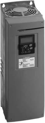
4 Presentation
5 Presentation (continued) 1 Applications A compact and robust variable speed drive for 3-phase asynchronous motors, the 1 incorporates the latest technological developments and its innovative functions meet the requirements of the most common applications, notably: b ventilation, b air-conditioning, b pumping, b conveying, b grinding, b handling and lifting. The has several application-specific preset configurations with a few basic parameters, which can be modified using the programming terminal 2 to create additional functions. The range extends across a range of motor power ratings from 2,2 to 710 kw (2 to 800 HP) for high torque applications and from 3 to 800 kw (3 to 800 HP) for standard torque applications with one single type of power supply from 525 to 690 V. Despite its high performance, it is easy to adjust. The introduction of elements on the motor rating plate and autotuning make it possible to obtain high torque together with remarkable drive quality, even at very low rotation speeds (< 0.5 Hz). For applications which require exceptional speed precision even at very low speed, and full torque at zero speed, a closed loop flux vector variable speed drive can be supplied. Functions The main functions are: b integrated PID drive (flow rate, pressure, speed correction), b 9 possible preset speeds, b JOG operation, b brake release sequences for translational movement and hoisting, b user-definable analogue and logic inputs, b ± speed, b skip frequencies, b local/remote control function, b logic functions, b starting and speed regulation via flux vector control, b multi-pump and fan control function, b protection of motor and variable speed drive, b automatic catching of spinning load with speed search (catch on the fly), b high overtorque on start-up, b separate 24 V c supply is possible for control circuit, b integrated line choke for protection against supply overvoltage and reduction of harmonic distortion.. Programming terminal The is supplied with a programming terminal which: b controls the variable speed drive in local mode, b configures the various parameters, b provides a remote display and indication of the variable speed drive status, b copies and backs up the parameters. Options Possible options, according to the rating: b additional I/O card 3, 11 available (see page 24), b PC-based setup software 4 (see page 24), b various dialogue and communication options 5 can be used with the drives (Modbus, Profibus DP, LonWorks, CANopen (slave), N2, DeviceNet communication cards) (see page 25), b braking resistors (see page 19), b dv/dt filters when motor cables are longer than 30 meters (see page 16), b remote mounting kit for programming terminal which enables installation of the terminal on the door of the enclosure or operator panel (see page 12), b enclosure kit for converting to IP 54 (NEMA Type 12) enclosure (see page 12). Characteristics: pages 6 to 9 References: pages 10 and 11 Dimensions: pages 28 to 33 Schemes: pages 38 and 39 3
6 Presentation, description 1 Dialogue Presentation of the programming terminal The variable speed drive has a detachable programming terminal on the front panel which allows: b Local control of the variable speed drive, b Configuration of different parameters, b Remote display and signalling of variable speed drive status, used in conjunction with a terminal support (see page 12). The programming terminal features an alphanumeric display with six indicators for variable speed drive status (RUN,, STOP, READY, ALARM, FAULT) and three indicators for control (I/O Term, Keypad, Bus/comm). There are also three status indicators LEDs (ready, run, fault) Keypad pushbuttons The alphanumeric control keypad features 9 pushbuttons that are used for the control of the variable speed drive (and motor), parameter setting and value monitoring. reset START 8 1 This button is used to switch between the two most recent displays. This feature is useful when you want to see how the new value influences another value. STOP 9 2 Edit values select enter 3 Menu button right Move forward in menu Move cursor right (in parameter menu) Enter edit mode This button is used to reset active faults 5 Menu button left Move backward in menu Move cursor left (in parameter menu) Exit edit mode Hold down for 2 3 seconds to return to main menu 6 Edit values 7 This button is used to confirm selections and to reset fault history (2 3 seconds). 8 Start button Pressing this button starts the motor if the keypad is in active control mode. 9 Stop button Pressing this button stops the motor (unless disabled by parameter R3.4/R3.6). 4
7 Description (continued) 1 Dialogue RUN STOP READY ALARM FAULT I/O Term Keypad Bus/comm Hand OFF Auto run ready fault Operator interface 1 RUN Motor is running. Blinks when the stop command has been given but the frequency is still ramping down. 2 Indicates the direction of motor rotation. 3 STOP Indicates that the drive is not running. 4 READY Lights when AC power is on. In case of a trip, the symbol will not light up. 5 ALARM Indicates that the variable speed drive is running outside a certain limit and a warning is given. 6 FAULT Indicates variable speed drive was stopped due to unsafe operating conditions. 7 I/O Term START/STOP commands or reference values, etc. are given by the I/O terminals. 8 Keypad The motor can be started or stopped, or its reference values, etc. altered from the keypad. 9 Bus/comm The variable speed drive is controlled through a fieldbus. 10 ready Illuminates with the AC power connected to the variable speed drive. Simultaneously, the status indicator READY is lit up. 11 run Illuminates when the variable speed drive is running. Blinks when the STOP button has been pushed and the variable speed drive is ramping down. 12 fault Illuminates when variable speed drive stops due to unsafe operating conditions. Simultaneously, the status indicator FAULT blinks on the display and the fault description can be seen. 13 Location indication: displays the symbol and number of menu, parameter etc. Example: M2 = Menu 2 (Parameters); P2.1.3 = Acceleration time 14 Description line: displays the description of menu, value or fault. 15 Value line: displays the numerical and textual values of references, parameters etc. and the number of submenus available in each menu. 5
8 Characteristics 1 Environment characteristics Conforming to standards Product certifications drives have been developed to conform to the strictest national and international standards and the recommendations relating to electrical industrial control devices (IEC, EN, NFC, VDE), in particular: - low voltage: EN 50178, - electrical isolation: conforming to EN 50178, PELV, - EMC immunity: conforming to IEC , EN , -2, - EMC emission: conforming to IEC UL, CSA, GOST, CE, C-TICK e Marking These variable have been designed to comply with the essential recommendations of the following European directives: - low Voltage Directive 73/23 EC, - EMC Directive 89/336 EC for industrial environments. To indicate this, products are marked with the European community e marking Degree of protection IP 21/NEMA 1 or IP 54/NEMA 12 from ATV 78pU22Y to ATV 78pC16Y IP 54/NEMA 12 kit for IP 21/NEMA 1 products from ATV 78pU22Y to ATV 78pD22Y installable in the field IP 00/ open type from ATV 780C20Y to ATV 780C71Y Maximum ambient pollution Level 2 conforming to IEC and EN Maximum relative humidity and Environmental class Ambient temperature around the device 3C2, according to IEC Storage C Operation (with a switching frequency of 1.5 khz, for a higher frequency see the derating current values below) 95 % without condensation or dripping water, conforming to IEC C High torque rating: -From ATV 78pU22Y to ATV 78pC16Y: - 10 (no frost) From ATV 780C20Y to ATV 780C71Y or ATV 780FC20Y to ATV 780FC71Y: - 10 (no frost) + 40 Standard torque rating: - 10 (no frost) + 40 Derating current values khz To operate at a switching frequency from 1.5 to 6, select the motor rating according to the derating current value given in the table below: Inv = max. nominal current of variable speed drive ATV 78p/ ATV 78pF U22Y to D90Y C11Y to C71Y Ambient Temperature Switching frequency (khz) C Inv Inv Inv Inv Inv 0.93 Inv 40 C Inv 0.90 Inv Vibration resistance Hz conforming to IEC/EN 50178/ and ( , -35, -36) Displacement amplitude 3 mm (peak) at Hz Max acceleration amplitude 0.7 gn at Hz Shock resistance Conforming to EN 50178/EN UPS drop test (for applicable UPS weights) Storage and shipping: max 15 gn, 11 ms (in package) Maximum operating altitude m 1000 without derating derating the current by 1 % per additional 100 m Operating position Maximum permanent angle in relation to the normal vertical mounting position 0.82 Inv 0.74 Inv 0.67 Inv 0.62 Inv 0.85 Inv 0.53 Inv 0.75 Inv 0.47 Inv Presentation: pages 2 and 3 References: pages 10 and 11 Dimensions: pages 28 to 33 Schemes: pages 38 and 39 6
9 Characteristics (continued) 1 Drive characteristics Output frequency range Hz Frequency stability: ± 0.01 % at 50 Hz Resolution: 0.01 Hz Switching frequency khz 1.5 6, factory default 1.5 Speed range in high torque configuration, close loop vector mode Speed accuracy Without encoder feedback card: - 30 % of nominal slip, speed > 10 % of nominal motor speed, - 50 % of nominal slip, speed < 5 % of nominal motor speed. With encoder feedback in control mode: ± 0.01 % of nominal speed Transient overtorque on start-up 200 % of nominal motor torque (typical value ± 10 %) in high torque configuration, 150 % in standard torque configuration Maximum transient current V: 150 % of nominal current in high torque operation for 60 s then 100 % in continuous operation 110 % of nominal current in standard torque operation (variable torque) for 60 s then 100 % in continuous operation Braking torque Up to 30 % of nominal motor torque without braking unit (typical value) Up to 100 % with external brake resistor Control method ATV 78ppppY: flux vector control without sensor; constant torque or variable torque. ATV 78pFpppY: flux vector control with sensor for more accurate speed control and torque control Electrical characteristics 3-phase power supply Voltage V V, ± 10 % Frequency Hz Output voltage Efficiency Maximum voltage equal to line supply voltage 97.5 % (including line choke losses), at 50/60 Hz at nominal load Available internal supplies V output %, 10 ma maximum, with short-circuit protection V output ± 15 %, 150 ma maximum with short-circuit protection Analogue inputs AI1 1 analogue voltage input 0 10 V Impedance 200 kω Precision ± 1 % of full scale (10 V) 10-bit resolution AI2 1 analogue current input: 0 (4) 20 ma differential Maximum load: 250 Ω 10-bit resolution Analogue output AO Analogue current output 0 (4) 20 ma with programmable operations Maximum external load < 500 Ω 10-bit resolution, accuracy ± 3 % Logic inputs DIp 6 bipolar inputs: positive or negative logic, c V Programmable operations, impedance > 5 kω State 1 above 18 V, state 0 below 10 V Auxiliary power supply Used to supply the control circuit and option cards via an external + 24 V if the main power supply is cut V input ± 15 %, 300 ma minimum Separated from the internal power supply by a diode Output relay Programmable relay Switching voltage: c 24 V/6 A, a 250 V/6 A, c 125 V/0.4 A Max. continuous current < 2 A RMS Min. switched current 5 V/ 10 ma Electrical isolation between the line supply and the relay power supply Signalling Via 3 indicator lamps on the programming terminal, - green power on, - green drive running, - red drive fault. Presentation: pages 2 and 3 References: pages 10 and 11 Dimensions: pages 28 to 33 Schemes: pages 38 and 39 7
10 Characteristics (continued) 1 Protection characteristics Overcurrent Trip limit 4.0 x I H (nominal drive current) instantaneously Overvoltage V c 1200 Undervoltage V c 461 Earth fault In case of earth fault in motor or motor cable, only the frequency converter is protected Input phase loss Trips if any of the input phase is missing Output phase loss Trips if any of the output phase is missing Overtemperature C Yes, warming at 85 and trip at 95 Motor thermal overload Yes, calculation of I 2 t Motor stall Yes Motor underload Yes Short-circuit protection of + 24 V and + 10 V reference voltage Yes Presentation: pages 2 and 3 References: pages 10 and 11 Dimensions: pages 28 to 33 Schemes: pages 38 and 39 8
11 Characteristics (continued) Operation 1 T/Tn 4 3 Torque characteristics (typical curves) The curve below defines the available continuous torque and transient torque, either on a naturally-cooled or a forced-cooled motor. The only difference is the ability of the motor to provide a high continuous torque at less than half nominal speed Naturally-cooled motor: continuous useful torque 2 Force-cooled motor: continuous useful torque (1) 3 Transient torque (1) 4 Possible overtorque at low speed (1) 5 Overspeed torque at constant power (2) Torque characteristics Hz (1) Torque available at zero speed with encoder feedback card. (2) Warning: check with the motor manufacturer regarding the mechanical overspeed possibilities of the selected motor. Special uses Motor power rating different from that of speed drive The variable speed drive can supply any motor which has a power rating between 20 and 120 % of that for which it is designed. Ensure that the current drawn does not exceed the continuous output current of the drive. Motors connected in parallel The variable speed drive rating must be greater than the sum of the motor currents to be connected to the variable speed drive. In this case, external thermal protection must be provided for each motor by probes (up to 6 motors) or a thermal overload relay. If the total length of the cables is greater than 30 m (100 feet), the fitting of a line choke between the variable speed drive and the motor is recommended (dv/dt filter is recommended at 525/660/690 V). Autotuning is necessary for applications which require a high start-up torque (conveyors, lifting). In this case, the motors should be mechanically coupled, should have the same power rating and the same cable length. Autotuning is not necessary for applications which do not require a high start-up torque (pumps, fans). In this case, the motor power ratings and the cable lengths may be different. Each motor can be isolated by a contactor during operation. On the other hand, the motor should be reconnected to the variable speed drive in accordance with the precautions described below: Coupling a contactor downstream of the variable speed drive. The nominal current set for the variable speed drive should be equal to the sum of the motor currents. Coupling a motor downstream of the speed drive Connecting on the fly is possible if the current peak of the motor to be connected is less than the current supported by the variable speed drive at the time of coupling. In all cases it is preferable to lock the variable speed drive before closing the contactor and unlock it after closing the main poles of the contactors. Connection to an IT network This type of connection is possible, but radio interference filters cannot be mounted. In addition, if the stray capacitance (or the filter capacitors) between the network and earth are excessive, there is a risk of premature wear on the variable speed drive in the event of a prolonged earth fault. Presentation: pages 2 and 3 References: pages 10 and 11 Dimensions: pages 28 to 33 Schemes: pages 38 and 39 9
12 References M M ATV 782D11Y ATV 782C16Y High torque applications (150 % Tn) Motor Power rating on motor plate Input/output current (1) Transient 525 V 575 V 660 V 690 V Nominal drive current (2) 150 % overload current (3) ouput current (4) Power dissipated at nominal load Reference (5) (6) Weight (7) kw HP kw kw A A A W kg 3-phase power supply voltage 525 V - 10 % 690 V + 10 % 50/60 Hz ATV 78pU22Y ATV 78pU30Y ATV 78pU40Y ATV 78pU55Y , ATV 78pU75Y ATV 78pD11Y ATV 78pD15Y ATV 78pD18Y ATV 78pD22Y ATV 78pD30Y ATV 78pD37Y ATV 78pD45Y ATV 78pD55Y ATV 78pD75Y ATV 78pD90Y ATV 78pC11Y ATV 78pC13Y ATV 78pC16Y ATV 780C20Y (8) ATV 780C25Y (8) ATV 780C31Y (8) ATV 780C35Y (8) ATV 780C45Y (8) ATV 780C50Y (8) ATV 780C56Y (8) ATV 780C63Y (8) ATV 780C71Y (8) High torque applications with integrated encoder feedback card In the hereabove references, replace ATV 78p with ATV 78pF. Example : ATV 78pU22Y becomes ATV 78pFU22Y, ATV 780C71Y becomes ATV 780FC71Y. (1) The input and output current values are about the same at nominal speed and nominal load. (2) The current rating is according to a standard 4 poles class B motor. (3) 150 % current overload for 1 minute every 10 minutes. (4) Transient output current for 2 seconds every 20 seconds. (5) In the reference, replace the p with 2 for a drive IP 21 (NEMA type 1) or 5 for a drive IP 54 (NEMA type 12). Example : ATV 782U22Y for IP 21 or ATV 785U22Y for IP 54. From ATV 780C20Y to ATV 780C71Y, the product is only available in IP 00 (open type) from the factory. (6) The conformal coating is available by adding suffix S337 to part number from ATV 785U22Y to ATV 785C16Y and ATV 780C20Y to ATV 780C71Y. Examples: ATV 785D75Y becomes ATV 785D75YS337. (7) The weight includes drive and line choke. (8) The line chokes are supplied with the variable, but not integrated. Presentation: pages 2 and 3 Characteristics: pages 6 to 9 Dimensions: pages 28 to 30 Schemes: pages 38 and 39 10
 110 % overload current (3) ouput current (4) Power dissipated at nominal load Reference (5) (6) Weight (7) kw HP kw kw A A A W kg 3-phase power supply voltage 525 V -")
13 References (continued) M M ATV 782D11Y ATV 782C16Y Standard torque applications (110 % Tn) Motor Power rating on motor plate Input/output current (1) Transient 525 V 575 V 660 V 690 V Nominal drive current (2) 110 % overload current (3) ouput current (4) Power dissipated at nominal load Reference (5) (6) Weight (7) kw HP kw kw A A A W kg 3-phase power supply voltage 525 V - 10 % 690 V + 10 % 50/60 Hz ATV 78pU22Y ATV 78pU30Y ATV 78pU40Y ATV 78pU55Y ATV 78pU75Y ATV 78pD11Y ATV 78pD15Y ATV 78pD18Y ATV 78pD22Y ATV 78pD30Y ATV 78pD37Y ATV 78pD45Y ATV 78pD55Y ATV 78pD75Y ATV 78pD90Y ATV 78pC11Y ATV 78pC13Y ATV 78pC16Y ATV 780C20Y (8) ATV 780C25Y (8) ATV 780C31Y (8) ATV 780C35Y (8) ATV 780C45Y (8) ATV 780C50Y (8) ATV 780C56Y (8) ATV 780C63Y (8) ATV 780C71Y (8) (1) The input and output current values are about the same at nominal speed and nominal load. (2) The current rating is according to a standard 4 poles class B motor. (3) 150 % current overload for 1 minute every 10 minutes. (4) Transient output current for 2 seconds every 20 seconds. (5) In the reference, replace the p with 2 for a drive IP 21 (NEMA type 1) or 5 for a drive IP 54 (NEMA type 12). Example : ATV 782U22Y for IP 21 or ATV 785U22Y for IP 54. From ATV 780C20Y to ATV 780C71Y, the product is only available in IP 00 (open type) from the factory. (6) The conformal coating is available by adding suffix S337 to part number from ATV 785U22Y to ATV 785C16Y and ATV 780C20Y to ATV 780C71Y. Examples: ATV 785D75Y becomes ATV 785D75YS337. (7) The weight includes drive and line choke. (8) The line chokes are supplied with the variable, but not integrated. Presentation: pages 2 and 3 Characteristics: pages 6 to 9 Dimensions: pages 28 to 30 Schemes: pages 38 and 39 11

14 References 1 Accessories DF Programming terminal remote mounting kit The is supplied with a detachable programming terminal (see page 4). A terminal support option allows remote mounting of the programming terminal at a distance of 2 or 15 metres. It is particularly suitable for mounting on the enclosure door. The programming terminal remote mounting kit includes: b terminal support, b connection cable (2 or 15 m lengths), b screws and washers. Description Cable length m For drives Reference Weight kg Terminal support 2 ATV 78 all ratings VW3 A ATV 78 all ratings VW3 A VW3 A7810p PC-based setup software ATV 78 Soft The PC software is provided in a CD-ROM, shipped with the product. The PC connection kit allows the connection between the PC operating in a Microsoft Windows environment. Minimum PC configuration: Pentium 3 processor with 128 Mb of RAM. Operating system: Windows 95, 98, NT, 2000 or XP. Main functions: b drive configuration, b configuration backup, b print out of complete parameter list, b parameters comparison, b load a configuration from one drive to another, b oscilloscope mode for maintenance, b control and monitoring. Description Cable length m For drives Reference Weight kg PC cable 1.5 ATV 78 all ratings VW3 A IP 54 kit (NEMA Type 12) The IP 54 kit enhances the enclosure IP 21 protection class of the variable speed drive to IP 54 protection class. The IP 54 enclosure provides protection against dust and water sprayed from all directions. However, it does not protect the variable speed drive against strong jets of water or if it is immersed. The IP 54 kit includes: b IP 54 enclosure, b IP 54 lid with fan, b cable entry flange with rubber grommets, b rubber sealings, b screws, cable anchors, fastening straps, warning sticker. Description For drives Reference Weight kg IP 54 kit ATV 782U22Y...2D22Y ATV 782FU22Y...2FD22Y VW3 A Dimensions: page 30 12
 may be flange mounted in a wall of the enclosure with the heatsink on the outside. This requires a cutout in the enclosure and a flange mounting kit.")
15 References 1 Accessories Flange mounting kit To reduce power dissipated in the enclosure, the variable speed drive IP 20/NEMA type 1 from 2.2 to 160 kw (2 to 150 HP) may be flange mounted in a wall of the enclosure with the heatsink on the outside. This requires a cutout in the enclosure and a flange mounting kit. For flange mounting, the heatsink and fan on the outside of the enclosure are IP 54/NEMA type 12 degree of protection. The flange mounting kit includes: b gaskets, b top and bottom flange, b fan, b sealing tape, b cable tie, screws, b instructions and cutout dimensions. For drives Reference Weight kg ATV 782U22Y 2D22Y ATV 782FU22Y 2FD22Y VW3 A ATV 782D30Y and 2D37Y ATV 782FD30Y and 2FD37Y ATV 782D45Y 2D75Y ATV 782FD45Y 2FD75Y ATV 782D90Y 2C16Y ATV 782FD90Y 2FC16Y VW3 A VW3 A VW3 A DF Demo case The demo case can be used for demonstration purposes at a tradeshow, customer meeting, or product presentation. It has a a 115/230 V dual voltage input rating. The demo case includes: b ABS case, b variable speed drive with keypad display, b power cord and PC connection cable, b PC software, b switches, LED s and analog meter. VW3 A78DEMO Description Reference Weight kg demo case VW3 A78DEMO
16 Presentation 1 Reduction of harmonic currents The main solutions for reducing harmonic currents are as follows: b line chokes (supplied with the ), b passive filters, b active compensators, also called Accusine active filters are marketed under the Merlin Gerin brand, b hybrid filters. All four solutions can be used on the same installation. It is always easier and less expensive to handle the harmonics at installation level as a whole rather than at the level of each individual unit, particularly when using passive filters and active compensators. Line chokes Presentation The has integrated line chokes to help reduce the current harmonic distortion generated by the variable speed drive itself and help improve protection against overvoltages on the line supply. The integrated line chokes in the are also used to minimize the line current. The use of line chokes is especially recommended in the following cases: b close connection of several variable in parallel, b line supply with significant interference from other equipment (interference, overvoltages, switching capacitors), b line supply with a voltage imbalance between phases > 1.8 % of nominal voltage, b line supply with a low impedance, e.g. the KVA of supply transformer is 10 times greater than the input KVA of the variable speed drive, b installation of a large number of variable on the same power supply, b if a power factor correction unit is installed, the line choke reduces the overload of the power factor (cos ϕ) correction capacitors and limits the voltage spikes caused by capacitor switching. Example of currents and harmonic levels at 690 V, 50 Hz H1 H5 H7 H11 H13 at 150 % Tn at 110 % Tn at 150 % Tn at 110 % Tn at 150 % Tn at 110 % Tn at 150 % Tn at 110 % Tn at 150 % Tn A A A A A A A A A A ATV 78pU22Y, pfu22y ATV 78pU30Y, pfu30y ATV 78pU40Y, pfu40y ATV 78pU55Y, pfu55y ATV 78pU75Y, pfu75y ATV 78pD11Y, pfd11y ATV 78pD15Y, pfd15y ATV 78pD18Y, pfd18y ATV 78pD22Y, pfd22y ATV 78pD30Y, pfd30y ATV 78pD37Y, pfd37y ATV 78pD45Y, pfd45y ATV 78pD55Y, pfd55y ATV 78pD75Y, pfd75y ATV 78pD90Y, pfd90y ATV 78pC11Y, pfc11y ATV 78pC13Y, pfc13y ATV 78pC16Y, pfc16y ATV 780C20Y, 0FC20Y ATV 780C25Y, 0FC25Y ATV 780C31Y, 0FC31Y ATV 780C35Y, 0FC35Y ATV 780C45Y, 0FC45Y ATV 780C50Y, 0FC50Y ATV 780C56Y, 0FC56Y ATV 780C63Y, 0FC63Y ATV 780C71Y, 0FC71Y at 110 % Tn Dimensions: pages 28 to 30 14
17 Characteristics, presentation 1 Reduction of harmonic currents Line chokes (continued) Characteristics Nominal current (In) (1) at 150 % Tn at 110 % Tn Line choke Inductance value Impedance value with In at 150 % Tn (high torque application) 525 V 60 Hz 575 V 60 Hz 660 V 50 Hz 690 V 50 Hz Impedance value with In at 110 % Tn (standard torque application) A A µh % % % % % % % % ATV 78pU22Y, pfu22y ATV 78pU30Y, pfu30y ATV 78pU40Y, pfu40y ATV 78pU55Y, pfu55y ATV 78pU75Y, pfu75y ATV 78pD11Y, pfd11y ATV 78pD15Y, pfd15y ATV 78pD18Y, pfd18y ATV 78pD22Y, pfd22y ATV 78pD30Y, pfd30y ATV 78pD37Y, pfd37y ATV 78pD45Y, pfd45y ATV 78pD55Y, pfd55y ATV 78pD75Y, pfd75y ATV 78pD90Y, pfd90y ATV 78pC11Y, pfc11y ATV 78pC13Y, pfc13y ATV 78pC16Y, pfc16y ATV 780C20Y, 0FC20Y ATV 780C25Y, 0FC25Y ATV 780C31Y, 0FC31Y ATV 780C35Y, 0FC35Y ATV 780C45Y, 0FC45Y ATV 780C50Y, 0FC50Y ATV 780C56Y, 0FC56Y ATV 780C63Y, 0FC63Y ATV 780C71Y, 0FC71Y (1) In is the nominal outpout current rating of variable speed drive in standard torque applications (110 % Tn) or in high torque applications (150 % Tn). 525 V 60 Hz 575 V 60 Hz 660 V 50 Hz 690 V 50 Hz Passive filters Active compensators Hybrid filters Presentation These work by trapping harmonic currents in LC circuits linked to the harmonic numbers to be filtered. The filter thus consists of steps, each step corresponding to a harmonic number. Numbers 5 and 7 are the most commonly filtered. The filter can be installed for a load or for a group of loads. Its design requires a detailed analysis of the supply and a research project. Its size depends on the harmonic range of the load and the impedance of the source. This type of filtering depends entirely on the source and the loads. It therefore offers very little flexibililty and almost no opportunity for upgrading the installation. Note: this type of filter can also be used to eliminate harmonic distortion which already exists on the line supply. Please consult your Regional Sales Office. Presentation These compensators, connected in parallel on the load and on the line supply, measure harmonic currents emitted by the equipment and automatically generate inverse harmonic currents. The advantages are as follows: - independence in relation to the load and to the supply impedance, - adaptive tuning. Note: please consult your Regional Sales Office. Presentation The hybrid filter is a device which comprises a passive filter and an active compensator and provides an excellent compromise for handling harmonics. Note: please consult your Regional Sales Office. Dimensions: pages 28 to 30 15
18 Presentation, references 1 Options: dv/dt long lead filters Presentation dv/dt long lead filter dv/dt are the steep-front voltage pulses that travel down the long leads in the circuit to the motor and subsequently revert back in a reflected wave. When the conductors are long enough, usually 30 metres (100 feet) or more, the time for reflection matches the time for transmission resulting in a high amplitude standing wave on the circuit. Voltage spikes of up to 2100 volts are frequently experienced for a 525/660/690 V systems, and equipment failures are the result. It is imperative to use the dv/dt filter. Installed between the variable speed drive and motor, dv/dt filter provides protection for the motor by slowing the rate of voltage increase and minimizing the peak voltage that occurs at the motor terminals. References For variable Maxi. length of cable dv/dt for a 525/660/690 V Reference Weight Shielded Unshielded Nominal Max. loss current m m A W kg ATV 78pU22Y pd15y ATV 78pFU22Y pfd15y VW3 A78601C 7 ATV 78pD18Y pd31y ATV 78pFD18Y pfd31y ATV 78pD45Y pd55y ATV 78pFD45Y pfd55y ATV 78pD75Y pd90y ATV 78pFD75Y pfd90y ATV 78pC11Y pc16y ATV 78pFC11Y pfc16y ATV 780C20Y ATV 780FC20Y ATV 780C25Y ATV 780FC25Y ATV 780C31Y ATV 780FC31Y ATV 780C35Y 0C50Y ATV 780FC35Y 0FC50Y ATV 780C56Y 0C71Y ATV 780FC56Y 0FC71Y VW3 A78602C VW3 A78603C VW3 A78604C VW3 A78605C VW3 A78606C VW3 A78607C VW3 A78608C VW3 A78609C VW3 A78610C 140 Dimensions: pages 31 16
19 Presentation 1 Options: output chokes Presentation The use of an output chokes between the drive and the motor is recommended for motor cables which are longer than 10 metres (30 feet). This makes it possible to: b limit dv/dt, b limit overvoltage on the motor terminal, b limit reflected wave from the motor back to the variable speed drive, b filter interference caused by opening a contactor placed between the reactor and the motor, b reduce the motor earth leakage current. Note: please consult your Regional Sales Office. 17
20 Presentation, characteristics 1 Options: braking resistors Presentation The dynamic braking transistor and braking resistor allow the variable speed drive to function in quadrants 2 and 4 of the four-quadrant speed/torque curve. In these quadrants of motor operation, the motor is essentially a generator through which energy is transferred from the motor load back to the variable speed drive. This results in elevated DC bus voltage to the variable speed drive, which may cause it to shut down to protect itself. Braking resistors are commonly used to dissipate the excess energy generated by the motor operating in this mode. The flow of current to the braking resistor is controlled by the dynamic braking transistor. The dynamic braking transistor is integrated in the from 2.2 to 160 kw (2 to 150 HP), and externally mounted from 200 to 710 kw (200 to 800 HP). Characteristics Type of braking resistors Ambient air temperature around the device Degree of protection of enclosure VW3 A78701L A78703L Storage C VW3 A78704L and A78705L VW3 A78706L and A78707L VW3 A78701H A78703H Operation C without derating Up to 80 C with current derating of 2.5 % per C above 40 If vertical mounting IP 50 IP 21 IP 20 IP 21 IP 20 In other cases IP 50 IP 20 IP 20 IP 20 IP 20 VW3 A78704H A78707H Thermal protection Via temperature controlled switch Temperature controlled switch Tripping temperature C 220 Selection: pages 20 to 23 Dimensions: pages 32 to 35 18
21 References 1 Options: braking resistors Braking resistors For variable Braking time 5 s (2) ATV 78pU22Y pu75y ATV 78pFU22Y pfu75y ATV 78pD11Y pd22y ATV 78pFD11Y pfd22y ATV 78pD30Y pd37y ATV 78pFD30Y pfd37y Minimum ohmic value at 20 (1) Braking resistors Power continuous Number of resistors resquired per drive Reference Weight Ω kw kg VW3 A78701L VW3 A78702L VW3 A78703L ATV 78pD45Y pd75y (3) VW3 A78704L ATV 78pFD45Y pfd75y (3) ATV 78pD90Y pc16y (3) VW3 A78705L ATV 78pFD90Y pfc16y (3) ATV 780C20Y 0C31Y and ATV 780FC20Y 0FC31Y ATV 780C35Y 0C50Y and ATV 780FC35Y 0FC50Y ATV 780C56Y 0C71Y and ATV 780FC56Y 0FC71Y VW3 A78706L VW3 A78707L VW3 A78706L Braking time 10 s (2) ATV 78pU22Y pu75y ATV 78pFU22Y pfu75y ATV 78pD11Y pd22y ATV 78pFD11Y pfd22y ATV 78pD30Y pd37y ATV 78pFD30Y pfd37y VW3 A78701H VW3 A78702H VW3 A78703H ATV 78pD45Y pd75y (3) VW3 A78704H ATV 78pFD45Y pfd75y (3) ATV 78pD90Y pc16y (3) VW3 A78705H ATV 78pFD90Y pfc16y (3) ATV 780C20Y 0C31Y and ATV 780FC20Y 0FC31Y ATV 780C35Y 0C50Y and ATV 780FC35Y 0FC50Y ATV 780C56Y 0C71Y and ATV 780FC56Y 0FC71Y VW3 A78706H VW3 A78707H VW3 A78706H Braking resistor connection kit For variable Reference Weight kg ATV 78pD45Y pc16y ATV 78pFD45Y pfc16y VW3 A (1) Do not use a resistor with a value less than the minimum value given in the table. (2) For special applications such as hoisting, please refer to the curves (see pages 22 and 23). (3) Braking resistor connection kit VW3 A78810 must be used. Selection: pages 20 to 23 Dimensions: pages 32 to 35 19
22 Selection 1 Options: braking resistors Determining the braking power Calculating the braking time from the inertia J ω t b π n ΣJ ( n = ω n 2 ) = T T b + T r 60 b = Pˆ b = 9,55 t b T b n ,55 Pb Pˆ b = T b Motor braking torque [Nm] J Total inertia applied to the motor [kgm 2 ] n 1 Motor speed ahead of gearbox [rpm] n 2 Motor speed after gearbox [rpm] t b Braking time [s] Pˆ b Peak braking power [W] P b Average braking power during time t b [W] t r Braking torque [mn] Motor n 1 Gearbox n 2 Machine J = J motor +J applied 1 i = n n 2 J applied J machine 2 i Braking power of a load moving horizontally with constant deceleration (eg.: carriage) W Kinetic energy [Joule] w Weight [kg] v Speed [m/s] W w v2 W = Pf = t b Pˆ b = Pb 2 t b Braking time [s] Pˆ b Peak braking power [W] P b Average braking power during time t b [W] Braking power for an active load (eg.: test bench) T b Braking torque [Nm] n Motor speed [rpm] T b n Pb = , 55 g Acceleration 9.81 m/s 2 a Deceleration [m/s 2 ] Braking power for a downward vertical movement v Linear downward speed [m/s] J Moment of inertia [kgms 2 ] ω Angular speed [rad/s] t b Downward stopping time [s] J ω Pb = w g v Pˆ 2 b w ( g + a) v π n = + ω = t b 60 All the braking power calculations are only true if it is assumed that there are no losses (η = 1) and that there is no resistive torque. Since all these points are important, an accurate assumption must be made: b Losses in the system, b The losses generated in the motor (working as a generator, quadrants II and IV) are of some help during the braking phase. Without exception, efficiency must be calculated to the braking power squared, b Resistive torque, b There may sometimes be resistive torque related to mechanical friction, air and opposing quadratic torque of the fans, b These phenomena, which are rarely taken into consideration, reduce the braking power, The resistive torque or the power should be deduced from the calculated braking power, b Driving torque. Additional phenomena, such as the wind, may cause an increase in the braking power. These phenomena should be taken into consideration. Pˆ br Maximum actual braking power [W] P br Continuous actual braking power [W] η total Total efficiency P load Braking power connected with the resistive or [W] driving torque (not taken into account in the calculation). P load can be positive or negative. η drive Drive efficiency = 0.98 η mec Mechanical efficiency Motor efficiency η mot The required braking power is calculated as follows: Pˆ br = ( P ˆ b P load ) η 2 total PbR = ( P b P load ) η 2 total η total = η mec η mot 0,98 Presentation: page 18 Characteristics: page 18 References: page 19 Dimensions: pages 32 to 35 20
23 Selection (continued) 1 Options: braking resistors ^ P max P contin Maximum braking power available with the braking unit Permanent thermal braking power [W] [W] U d Braking unit control level [V] I Braking resistor thermal current (see the TH setting) [A] P cycle Cycle See the braking cycle diagram 100 kw 60 s Example of selection of a braking resistance for a hosting application 5 s 150 kw 2,5 s To select the braking power ( Pb, P b ) it is also necessary to consider the following points when selecting the braking option: b Type of installation and protection of the braking resistors, b Wiring conditions, b Problems with heat dissipation (air conditioning), b Cost and possibility of depreciation of the installation due to the reduced costs of electrical energy. For braking, the braking resistor is selected to match the required power and the braking cycle. In general : Pˆ max d The drive has a protection device inside the braking resistor. See parameters of seting-up E3.06, E3.07 and E3.08. The protection curve and other advice is given in the programming guide. If this protection curve is suitable for your braking resistors, then it is possible to use the internal protection. If not, external protection must be provided by a thermal overload relay. Thermal overload relay P = nominal braking resistor power R = value of the resistor P = R I 2 P V I = = thermal overload relay rated value In the formula, we have: R ^ P max = Braking unit power + R Pcontinuous = I 2 R (Resistor P) Customer data: Calculations: U 2 d = R --- Pˆ max U 2 = d R Raising/lowering cyclee = 1 minute Cd/Cn = 1,38 Raising with rated load at steady state: 106 kw ηtotal = 0, kw leads to selection of a 120 kw motor 120 kw x 0,85 = 102 kw V 100 kw braking at steady state 102 kw x 1,38 = 140 kw V selection of 150 kw max braking power The speed drive used is a 132 kw ATV 782C13Y (min. braking resistance = 9 Ω) The minimum resistance to be used is determined as a function of the speed drive used with the aid of braking resistance cycle curves. Braking cycle: 60 s = 150 kw max. for 2.5 s and 100 kw for 5 s. Braking resistance VW3 A78705H can be used since it accepts 100 kw for more than 5 s and 150 kw for 2.5 s. Presentation: page 18 Characteristics: page 18 References: page 19 Dimensions: pages 32 to 35 21
24 Selection (continued) 1 Characteristics curves of braking resistors Permissible overload per braking resistor according to time VW3 A78701L (P continuous = 0.3 kw) VW3 A78702L (P continuous = 1.0 kw) kw t (s) kw t (s) VW3 A78703L (P continuous = 1.7 kw) VW3 A78704L (P continuous = 3.2 kw) kw t (s) kw t (s) VW3 A78705L (P continuous = 4.0 kw) VW3 A78706L (P continuous = 11 kw) kw kw t (s) t (s) VW3 A78707L (P continuous = 17 kw) kw t (s) P max (60 s cycle) P max (120 s cycle) P max (200 s cycle) Presentation: page 18 Characteristics: page 18 References: page 19 Dimensions: pages 32 to 35 22
25 Selection (continued) 1 Characteristics curves of braking resistors Permissible overload per braking resistor according to time (continued) VW3 A78701H (P continuous = 0.79 kw) VW3 A78702H (P continuous = 2.8 kw) kw t (s) kw t (s) VW3 A78703H (P continuous = 5.5 kw) VW3 A78704H (P continuous = 9.4 kw) kw t (s) VW3 A78705H (P continuous = 12 kw) kw t (s) VW3 A78706H (P continuous = 34 kw) kw t (s) kw t (s) VW3 A78707H (P continuous = 50 kw) kw t (s) P max (60 s cycle) P max (120 s cycle) P max (200 s cycle) Presentation: page 18 Characteristics: page 18 References: page 19 Dimensions: pages 32 to 35 23

26 Presentation, characteristics, references 1 Options: I/O extension cards Presentation Environmental characteristics Ambient air temperature around the device The variable speed drive is designed to accept a total of 5 option cards, including fieldbus cards, into 5 slots labelled from A to E located on the control basket. Operation C Storage C Maximum relative humidity % < 95, no condensation allowed Maximum operating altitude m 1000 Vibration resistance 0,5 gn at Hz Electrical characteristics Analogue inputs AI AIV 0 ± 10 V, R i u 200 kω, single-ended Resolution 10 bits/0.1 %, accuracy ±1 % of the full display ( V joystick control) AIC 0 (4) 20 ma, R i = 250 Ω, differential Resolution 10 bits/0.1 %, accuracy ± 1 % of the full display Analogue outputs AO AOV 0 (2) 10 V, R L u 1kΩ, resolution 10 bits, accuracy y ± 2 % AOC 0 (4) 20 ma, R L < 500 Ω, resolution 10 bits/0.1 %, accuracy y ± 2 % Digital inputs DI DC Control voltage c 24 V status 0 if < 5 V, status 1 if > 11 V AC Control voltage a V status 0 if < 33 V, status 1 if > 35 V Auxiliary voltage Output c 24 V (± 15 %), max 250 ma (total summarized load from ext. c 24 V outputs, max. 150 ma from one card) Input c 24 V (± 10 %, max. ripple voltage 100 mv RMS), max. 1A In special applications where PLC type functions are included in the control unit, the input can be used as external auxiliary power supply for control cards as well as I/O extension cards Output voltage 10 V %, max. 10 ma Open collector output DO 10 ma, c 48 V maximum Relay outputs RO Thermistor input TI Switching capacity c 24 V/8 A a 1250 V/8 A c 125 V/0.4 A Max. continuous load: 2 A rms Min. switching load: 5 V/10 ma R trip = 4.7 kω (PTC type) Encoder control voltage + 5 V/+ 12 V/+ 15 V/+ 24 V (see schemes page 38) Encoder connections Inputs, outputs (see schemes page 38) References Description Slot Reference Weight number kg 6DI, 1DO, 2AI, 1AO, + 10, 24 V/EXT + 24 V A VW3 A78201 (1) DF RO (NO/NC) B VW3 A78202 (1) RO (NO/NC), 1RO (NO), 1 thermistor input B VW3 A78203 (3) DI (Encoder RS 422), out + 5 V + 15 V C VW3 A78204 (2) (3) DI (Encoder V), out + 15 V + 24 V C VW3 A78205 (2) 3) DI, 1DO, 2AI, 1AO, + 10, 24 V/EXT + 24 V, A VW3 A78206 (3) all I/O are galvanically isolated Duplicate encoder card with two encoder inputs C VW3 A78207 (2) (3) (used as Master/Slave), + 15 V or + 24 V range V/Ext + 24 V, 3 Pt 100 B, C, D, E VW3 A78208 (3) VW3 A7820p 1RO (NO), 5 digital inputs a V B, C, D, E VW3 A78209 (3) isolated AO, 1AI B, C, D, E VW3 A RO (NO) B, C, D VW3 A (1) The cards VW3 A78201 and A78202 are integrated in the variable speed drive. (2) For Closed Loop Flux Vector Control applications, cards VW3 A78204, A78205 and A78207 must be used with the ATV 78pFpppp variable speed drive (see page 10). (3) The conformal coating is available by adding the suffix S337 to the part number. Exemple: VW3 A78201 becomes VW3 A78201S337. Schemes: page 38 24
27 Presentation, characteristics, references 1 Options: communication cards Presentation The variable speed drive can be adapted for communication by adding a communication card or module. The models are available for the following buses: Modbus, DeviceNet, Profibus DP, LonWorks and CANopen. Functions common to all fieldbuses option cards: b control (accessible in read and write): run/stop, speed reference, fault reset, etc. b Monitoring (only accessible in read): drive status register, motor speed, motor current, logic I/O status register, fault, register, etc. b Authorization of local control (via terminals). b Configuration (accessible in read and write): all variable speed drive parameter registers b Adjustment (accessible in read and write): ramp time, thermal protection, speed range, current limit, etc. Characteristics Protocol Modbus DeviceNet Profibus DP LonWorks N2 CANopen Number of devices on network Transmission speed Kbps Kbps Mbps 78 Kbaud 9.6 Kbps Mbps Data transfer method RS 485 half duplex RS 485 CANopen RS 485 half duplex Twisted pair Twisted pair CANopen (ISO 11898) References Description Slot Reference (1) Weight number kg Modbus: connected to fieldbus through a 5-pin plug-in bus connector. (possible N2) D, E VW3 A Profibus DP: connected to fieldbus through a 5-pin plug-in bus connector CANopen slave: connected to fieldbus through a 5-pin plug-in bus connector DeviceNet: connected to fieldbus through a 5-pin plug-in bus connector LonWorks: connected to fieldbus through a 3-pin plug-in bus connector D, E VW3 A D, E VW3 A D, E VW3 A D, E VW3 A VW3 A78307 (1) The conformal coating is available by adding the suffix S337 to the part number. Exemple: VW3 A78306 becomes VW3 A78306S337 Schemes: page 39 25
Presentation Soft starters 0 Altistart 48 soft start - soft stop units
 Presentation Soft starters 5 6 7 65_Ver.-EN.fm/ Presentation (continued) Soft starters Applications The Altistart 8 soft start - soft stop unit is a controller with 6 thyristors which is used for the torque-controlled
Variable speed controllers for asynchronous motors
 Contents Presentation, functions Page 14 Characteristics Pages 15 to 18 References Page 18 Options Page 19 Accessories : Braking resistors Page 20 Line chokes Page 21 Dimensions Pages 22 and 2 Schemes
Delta Products VFD CP2000 Bypass Control Packages.
 Delta Products VFD CP2000 Bypass Control Packages www.deltaww.com Delta Products VFD CP2000 Bypass Control Packages The Delta Products VFD CP2000 Bypass Control Packages are designed for the Delta Products
Varispeed E7. Varispeed E7. Varispeed. Varispeed E7. Varispeed E7. Varispeed E7 INVERTER SERIES
 INVERTER SERIES Varispeed E VARISPEED E YASKAWA INVERTER DRIVE TECHNOLOGY Contents Content Page 2 Experience & Innovation A leader in Drives technology Page 3 Specifications Experience & Innovation For
2.3. Adjustable Frequency Drives. Contents. Standards and Certifications
 Contents Selection................ Product Selection....................... Accessories........................... Technical Data and Specifications.......... Dimensions........................... Page
SD700FR. Regenerative Active Front End VARIABLE SPEED DRIVES POWER ELECTRONICS / SD700 SERIES 4 QUADRANT. icool
 FR VARIABLE SPEED DRIVES Regenerative Active Front End icool 4 QUADRANT POWER ELECTRONICS / SD700 SERIES FR SD700FR SERIES goes one step ahead keeping the family unique characteristics. Based on the latest
Observe all necessary safety precautions when controlling the soft starter remotely. Alert personnel that machinery may start without warning.
 Introduction OPERATING INSTRUCTIONS: MCD REMOTE OPERATOR Order Codes: 175G94 (for MCD 2) 175G361 + 175G9 (for MCD 5) 175G361 (for MCD 3) 1. Introduction 1.1. Important User Information Observe all necessary
Unidrive M400 Fast set-up and diagnostics with real-text display, integrated PLC and safety inputs
 Unidrive M400 Fast set-up and diagnostics with real-text display, integrated PLC and safety inputs 0.25 kw - 110 kw (0.33 hp - 150 hp) 100 V 200 V 400 V 575 V 690 V Unidrive M400 features Optional AI-485
JC-VSD FP Series II Drives Product Bulletin 1
 JC-VSD FP Series II Drives Product Bulletin Code No. LIT-12012081 Issued May 2017 The Johnson Controls VSD FP Series II provides the advanced technology and features of the Johnson Controls VSD Series
VSD Series II Variable Speed Micro Drives
 VSD Series II Variable Speed Micro Drives Product Bulletin Code No. LIT-12011813 Issued March 26, 2013 Refer to the QuickLIT website for the most up-to-date version of this document. Johnson Controls VSD
SmartVFD HVAC FEATURES APPLICATION SPECIFICATION DATA
 SmartVFD HVAC APPLICATION The SmartVFD HVAC is a variable frequency drive designed for use in HVAC application to control the speed of HVAC pumps and fans in order to maximize energy efficiency. Smart
A. Provide variable frequency drives to operate variable torque loads as shown on the Drawings and as specified herein.
 DIVISION 23 HEATING, VENTILATING, AND AIR CONDITIONING (HVAC) SECTION 23 90 71 PART 1 GENERAL 1.01 DESCRIPTION A. Provide variable frequency drives to operate variable torque loads as shown on the Drawings
www. ElectricalPartManuals. com Instruction Bulletin ALTIVAR FLEX58 TRX Adjustable Speed Chassis Drive Controllers Installation Guide
 Instruction Bulletin ALTIVAR FLEX58 TRX Adjustable Speed Chassis Drive Controllers Installation Guide Retain for future use. 30072-450-47A July 2002 Raleigh, NC, USA HAZARDOUS VOLTAGE Read and understand
690+ Series Integrator
 690+ Series Integrator V/F, Sensorless, Vector Inverter from 1 to 1600 DESCRIPTION The 690+ Series is a single range of AC drives designed to meet the requirements of all variable speed applications from
RVS-DN Digital Reduced Voltage Motor Starter
 RVS-DN Digital Reduced Voltage Motor Starter Specification Guide Specification Guide Contents 1.0 Introduction 2.0 Specifications 2.1 Standard Performance Features 2.2 Standard Protection Features 2.3
ALTIVAR 18 AC Drives. File 8805
 ALTIVAR 18 AC Drives File 8805 CATALOG CONTENTS Description....................................................Page Introduction........................................................ 1 Specifications....................................................
Burden Fuse Rating Resistor SAF / SAK6 1NM 10mm M8 12NM SAF / SAK10 2NM 16mm M8 12NM
 Contents Section Page 1.0 Introduction 1 2.0 Specification 1-4 3.0 Installation 5-8 4.0 Programming 9-10 5.0 Menus 10-12 6.0 Fault Finding/Diagnostics 12-13 7.0 Communication 13 8.0 Setting Up 13-16 1.0
GS2 Series - Introduction
 GS2 Series - Introduction GS2 Series Drives Rating Hp.25.5 1 2 3 5 7.5 10 kw 0.2 0.4 0.75 1.5 2.2 3.7 5.5 7.5 Single-Phase 115 Volt Class Single/Three-Phase 230 Volt Class Three-Phase 230 Volt Class Three-Phase
Drive Electronics \ Drive Automation \ System integration \ Services MOVITRAC LTP. Catalog. Edition 03/ / EN
 Drive Electronics \ Drive Automation \ System integration \ Services MOVITRAC LTP Edition 03/2009 Catalog 16798015 / EN SEW-EURODRIVE Driving the world 1 Important Notes... 4 1.1 Structure of the safety
Low voltage AC drives
 General machinery drives Main features and dimensions Unique features Fast and extensive I/O PID control Application macros Many installation possibilities 200 to 480 V, 1-phase or 3-phase More value for
V1000. Inverter Series.
 V1000 Inverter Series www.yaskawa.eu.com One for all The V1000 is a general purpose inverter drive covering the demands of a wide field of applications. Simple duties as well as requirements of complex
V1000 Inverter Series
 V1000 Inverter Series www.yaskawa.eu.com One for all The V1000 is a general purpose inverter drive covering the demands of a wide field of applications. Simple duties as well as requirements of complex
VSD Series II Variable Speed Open Drives
 VSD Series II Variable Speed Open Drives Product Bulletin Code No. LIT-12011824 Issued May 5, 2015 Refer to the QuickLIT website for the most up-to-date version of this document. The Johnson Controls VSD
 Standard Features 200-600V, 50/60Hz input power supply Built-in run rated (AC1) By-pass contactor up to 820 A * Rated 450% current Conformal coated circuit board Voltage ramp or current limit start modes
Lexium integrated drives
 Description ILp for CANopen, PROFIBUS DP, RS ILE with brushless DC motor Description ILE comprise control electronics with a fieldbus interface for CANopen DS, PROFIBUS DP or RS and a brushless DC motor.
Unidrive M600 High performance drive for induction and sensorless permanent magnet motors
 Unidrive M600 High performance drive for induction and sensorless permanent magnet motors 0.75 kw - 2.8 MW Heavy Duty (1.0 hp - 4,200 hp) 200 V 400 V 575 V 690 V Unidrive M600 features Easy click-in keypad
J1000 D E F I 1000 J1000 J1000 J1000 J1000
 Compact Inverter SERIES J1000 GB D E F I 1000 J1000 J1000 J1000 J1000 The J-Type YASKAWA Inverter Drive Technology Contents Page 2 Experience & Innovation A leader in Inverter Drives technology Page 3
USERS MANUAL MCD REMOTE OPERATOR
 USERS MANUAL MCD REMOTE OPERATOR Order Code: 175G9004, 175G3061 Contents Contents Introduction...2 Important User Information...2 General Description...2 Symbols Used in this Manual...2 Installation...3
RVS-DX Digital Reduced Voltage Motor Starter
 RVS-DX Digital Reduced Voltage Motor Starter Specification Guide Specification Guide Contents 1.0 Introduction 2.0 Specifications 2.1 Standard Performance Features 2.2 Standard Protection Features 2.3
Description 1/8-7.5HP
 Description 1/8-7.5HP J1000 In our pursuit to create drives optimized for variable speed needs in compact applications, the J1000 is the solution. This micro-drive is simple and reliable with Yaskawa quality.
Unidrive M700 Class leading performance with onboard real-time Ethernet
 Unidrive M Class leading performance with onboard real-time Ethernet. kw -.8 MW Heavy Duty (. hp -, hp) V V V 9 V Unidrive M features Easy click-in keypad connection Range of multi-language LCD keypads
1/2 thru 1.5 Hp 1/2 thru 3 Hp 2 thru 5 Hp 1 thru 10 Hp
 VS1MX AC Micro Drive 1/2 thru 1.5 Hp 1/2 thru 3 Hp 2 thru 5 Hp 1 thru 10 Hp & Controls 115 VAC 230 VAC 230 VAC 460 VAC 1 Phase - 50/60 Hz 1 Phase - 50/60 Hz 3 Phase - 50/60 Hz 3 Phase - 50/60 Hz Applications:
Phoenix DX Sensorless AC Vector Drive. 3 HP to 3500 HP
 Phoenix DX Sensorless AC Vector Drive 3 HP to 3500 HP Standard Features: * PRECISE CONTROL OF MOTOR SPEED AND TORQUE * BI-DIRECTIONAL FLYCATCHER (CATCH SPINNING MOTOR) * EASY TO USE, SIMPLE SETUP * POWER
Honeywell CORE Drive FEATURES APPLICATION SPECIFICATION DATA
 Honeywell CORE Drive SPECIFICATION DATA FEATURES APPLICATION The new Honeywell VFD CORE Drive addresses the need to save time for installation, and provides the lower total installed costs with years of
VSD Series II Variable Speed Enclosed IntelliPass and IntelliDisconnect Drives
 VSD Series II Variable Speed Enclosed IntelliPass and IntelliDisconnect Drives Product Bulletin Code No. LIT-12011814 Issued February 4, 2013 The Johnson Controls VSD Series II Variable Speed Enclosed
LIFT INVERTER SERIES L1000V DE ES FR IT 1000V L1000V L1000V L1000V L1000V
 LIFT INVERTER SERIES EN DE ES FR IT 1000V YASKAWA INVERTER DRIVE TECHNOLOGY Contents Page 2 Introduction Experience & Innovation YASKAWA speaks Lift Page 3 YASKAWA Main Features Page 4 Specifications Page
RVS-AX Instruction Manual
 RVS-AX Analog Soft Starter 8-170A, 220-600V Instruction Manual Ver. 10/11/2009 2 Table of Content RVS-AX Instruction Manual 1. TABLE OF CONTENT 1. Table of Content...2 2. Safety & Warnings...3 2.1 Safety...3
SINUS PENTA 2T/4T SINUS PENTA 2T/4T
 SINUS PENTA 2T/4T SINUS PENTA 2T/4T Technical Highlights One product, 5 integrated functions - IFD (Inverter Frequency Drive): vector modulation function for general-purpose applications (V/F pattern).
TRIPS AND FAULT FINDING
 WWW.SDS.LTD.UK 0117 9381800 Trips and Fault Finding Chapter 6 6-1 TRIPS AND FAULT FINDING Trips What Happens when a Trip Occurs When a trip occurs, the drive s power stage is immediately disabled causing
ADJUSTABLE FREQUENCY CONTROLS SENSORLESS VECTOR CONTROL. Dual Rating. Technologies Inc. mgitech.com NRTL/C CERTIFIED
 ADJUSTABLE FREQUENCY CONTROLS SENSORLESS VECTOR CONTROL Dual Rating NRTL/C CERTIFIED Technologies Inc. mgitech.com Sensor/Sensorless Vector Control Dual current rated for constant and variable torque Auto
J1000. Compact Inverter Series.
 J1000 Compact Inverter Series www.yaskawa.eu.com Focus on Application Customer orientation and application focus two attributes of machine equipment YASKAWA offers with its J1000 compact inverter drive
ALTIVAR FLEX58 Chassis Drive Controller Product Selection
 ALTIVAR FLEX58 Chassis Drive Controller Product Selection Class 8806 CONTENTS Description Page General Information and Selection....................................... 2 Specifications and Ratings...........................................
CTi Automation - Phone: Fax: Web:
 CTi Automation - Phone: 800.894.0412 - Fax: 208.368.0415 - Web: www.ctiautomation.net - Email: info@ctiautomation.net The control & protection you expect in an innovative soft starter design... Flexibility
Lexium integrated drives
 Description ILp for DeviceNet, EtherCAT, Modbus TCP, ILE with brushless DC motor Description ILE comprise control electronics with a fieldbus interface for DeviceNet, EtherCAT, Modbus TCP or and a brushless
SYSDrive Frequency Inverter
 SYSDrive Frequency Inverter T V/f control T PID control T Standard LED, optional LCD operator T Fieldbus options: DeviceNet T 7 configurable digital inputs T 3 configurable digital outputs T Low audible
Application Description
 -14 Type, Intelligent Technologies (IT.) Soft Starters February 2007 Contents Description Page Type, Intelligent Technologies (IT.) Soft Starters Product Description....... -14 Application Description....
Low voltage AC drives. ABB micro drives ACS to 3 hp/0.18 to 2.2 kw Catalog
 Low voltage AC drives ABB micro drives ACS55 0.25 to 3 hp/0.18 to 2.2 kw Catalog ACS55 IP20 Overview ACS55 micro drives are designed for use in a wide variety of simple machinery applications where only
VARMECA variable speed asynchronous motors with FCR brake LS VARMECA FCR. General information
 General information VARMECA, the result of long experience in variable speed, benefits from a a compact size and reduced weight. Currently it is available up to 11. VARMECA generates no noise pollution
Shenzhen Sine Electric Co., Ltd.
 Page 1 of 5 Favorite Contact 中文 Please enter key words 提交查 Home Products Solutions Service About us Products EM500 Open loop Inverter Your current location:home > Products Standard Inverters EM500 Open
SINAMICS GM150 IGCT version
 /2 Overview /2 Benefits /2 Design /6 Function /8 Selection and ordering data /8 Options Technical data /14 General technical data /15 Control properties /15 Ambient conditions /16 Installation conditions
sinamics SINAMICS G110 Variable Speed Drives 0.12 kw to 3 kw SINAMICS G110 Short Form 2004
 Variable Speed Drives 0.12 kw to 3 kw Short Form 2004 sinamics SINAMICS Variable Speed Drives 0.12kW to 3kW Product Information Pricing The is a Variable Speed Drive with basic functions for a variety
Variable Speed Drives Controlling Centrifugal Pumps Energy Savings
 2018 Clean and Safe Drinking Water Workshop Hotel Gander Variable Speed Drives Controlling Centrifugal Pumps Energy Savings Presenter: Dave Galbraith What is a Variable Speed (Frequency) Drive? AKA VFD,
AQUAVAR Intelligent Pump Controller TECHNICAL BROCHURE BCPAQIPC R2
 AQUAVAR Intelligent Pump Controller TECHNICAL BROCHURE BCPAQIPC R2 INTRODUCTION The Aquavar Intelligent Pump Controller from utilizes an all new Aquavar platform, and combines it with over 20 years of
CATALOG. ABB micro drives ACS55, 0.18 to 2.2 kw
 CATALOG ABB micro drives ACS55, 0.18 to 2.2 kw 2 ABB MICRO DRIVES, ACS55, 0.18 TO 2.2 KW/0.25 TO 3 HP Ease of integration. ACS55 drives. 3 Table of contents 004 ABB micro drives, ACS55 005 Easily integrated
Powerdrive FX Ultra compact regenerative drive solution
 Powerdrive FX Ultra compact regenerative drive solution 22 kw - 90 kw (30 hp - 125 hp) 400 V 480 V Powerdrive FX Drives with dynamic braking Based on innovative C-Light 4 Quadrant technology, the variable
1/2 thru 1.5 Hp 1/2 thru 3 Hp 2 thru 5 Hp 1 thru 10 Hp
 VS1MX AC Micro Drive 1/2 thru 1.5 Hp 1/2 thru 3 Hp 2 thru 5 Hp 1 thru 10 Hp & Controls 115 VAC 230 VAC 230 VAC 460 VAC 1 Phase - 50/60 Hz 1 Phase - 50/60 Hz 3 Phase - 50/60 Hz 3 Phase - 50/60 Hz Applications:
DENVER PUBLIC SCHOOLS DESIGN AND CONSTRUCTION STANDARDS This Standard is for guidance only. SECTION MOTORS, STARTERS & DRIVES
 PART 0 DESIGN STANDARDS 0.01 GENERAL DESIGN GUIDELINES A. Coordinate starter needs for mechanical equipment prior to 50% CD and confirm again for 100% CD submittal. B. Coordinate temperature controls requirements
SMS PRODUCT CATALOGUE
 SMS PRODUCT CATALOGUE CONTENTS 1 TAKEDO 3VF-NXP - LIFT INVERTER Page 3 2 TAKEDO 3VF-V20 - OPEN LOOP LIFT INVERTER Page 6 3 TAKEDO ENERGY - DYNAMIC BRAKING REGENERATIVE UNIT Page 7 4 HYDROVERT VVVF FOR
ALTIVAR 58 AC Drives
 Class 8806 / 8839 / 8998 CONTENTS Schneider Electric Brands Page ALTIVAR 58 AC Drives............................................... 3 Drives Overview...................................................
Low voltage AC drives. ABB component drives ACS to 2.2 kw / 0.25 to 3 hp Catalog
 Low voltage AC drives ABB component drives ACS55 0.18 to 2.2 kw / 0.25 to 3 hp Catalog ABB component drives ABB component drives ABB component drives are designed to be incorporated into a wide variety
Concentrated savings for your applications. Altivar Medium-voltage variable speed drive 0.5 to 10 MW. DIA2ED EN.indd 1 17/07/08 8:58:49
 Concentrated savings for your applications Altivar 1000 Medium-voltage variable speed drive 0.5 to 10 MW DIA2ED1080701EN.indd 1 17/07/08 8:58:49 Altivar 1000: a compact heavyweight response to your needs
Concentrated savings for your applications. Altivar Medium-voltage variable speed drive 0.5 to 10 MW
 Concentrated savings for your applications Altivar 1000 Medium-voltage variable speed drive 0.5 to 10 MW Altivar 1000: a compact heavyweight response to your needs for medium-voltage speed control Power
BR Second Position Voltages. AA Fourth Position
 1336S First Position Bulletin Number BR Second Position Voltage Letter AQ BR CW A B BP BX C Q R RX W Voltages 200-240V AC or 3V DC 380-480VAC or 513-620V DC 500-600V AC or 775V DC or 200-240V AC 380-480V
Quick Start Guide of CV50- ControlVIT Series
 ❶ Safety precautions Do not refit the inverter unauthorizedly; otherwise fire, electric shock or other injury may occur. Please install the inverter on fire-retardant material and keep the inverter away
Frequency inverters overview
 Frequency Inverter Frequency inverters overview Frequency inverters of TOSHIBA convince plant manufacturers and machine operators worldwide due to high reliability in operation and flexibility in application.
Variable speed drive ALSPA MV1000. Power Conversion. General Drives
 Variable speed drive ALSPA MV1000 Power Conversion General Drives 1 ALSPA MV1000 Intelligent drive technology Your drive requirements have been satisfied through the development of our ALSPA MV1000 range.
L300P Inverter Specifications
 L300P Inverter Specifications Tables for 200V class inverters Note that General Specifications on page 1 9 covers all L300P inverters, followed by footnotes for all specifications tables. Seven 200V models
SINAMICS SM150. 4/2 Overview. 4/2 Benefits. 4/2 Design. 4/6 Function. 4/8 Selection and ordering data. 4/8 Options
 /2 Overview /2 Benefits /2 Design /6 Function /8 Selection and ordering data /8 Options Technical data /1 General technical data /15 Control properties /15 Ambient conditions /16 Installation conditions
Data Bulletin. ALTIVAR FLEX58 Chassis Drive Controllers Class 8806 INTRODUCTION DESIGN CONCEPT. Bulletin No. 8806DB0102 August 2001 Raleigh, NC, USA
 Data Bulletin Raleigh, NC, USA ALTIVAR FLEX58 Chassis Drive Controllers Class 8806 INTRODUCTION The ALTIVAR FLEX58 chassis drive controller offers OEMs, panel builders, integrators, and users a unique
ABB Softstarter Benefits Charnchanok Thongprad
 ABB Softstarter Benefits Charnchanok Thongprad tomation Technology Products AB Control - 1 - - Why Softstarters? Benefits for the Electrical network Reduces voltage drops on networks Minimizes starting
MaxPak Plus Analog DC V S Drive
 Three-Phase 3-600 HP non-regenerative and 5-150 HP regenerative drives Designed to accommodate a wide range of industrial requirements, the DC V S Drive has been widely applied worldwide. Selected ratings
SECTION MOTOR CONTROL
 SECTION 26 24 19 MOTOR CONTROL PART 1 - GENERAL 1.1 SECTION INCLUDES A. Manual motor starters B. Magnetic motor starters C. Combination magnetic motor starters D. Solid-state reduced voltage motor starters
Softstarters. Softstarters Type SSM Medium voltage ,800V 1
 Medium voltage 2300 13,800V 1 Description Fused disconnect switch with blown fuse indicators and door safety interlocks rated for load break/fault make with automatic grounding arm Inline isolation vacuum
University of Houston Master Construction Specifications Insert Project Name SECTION ELECTRONIC VARIABLE SPEED DRIVES PART 1 - GENERAL
 SECTION 23 04 10 ELECTRONIC VARIABLE SPEED DRIVES PART 1 - GENERAL 1.1 RELATED DOCUMENTS: A. The Conditions of the Contract and applicable requirements of Division 1, "General Requirements", and Section
Symbol Input rating Symbol 2 Three-phase, 200 ~ 230V N 4 Three-phase, 380 ~ 480V. None. Loader. Graphic. Loader
 is7 Variable Frequency Drive / Inverter High Torque Performance and Precise VFD 3 phase 0.75~22kW(1~30HP), 200~230V 3 phase 0.75~160kW(1~250HP), 380~480V Constant torque / Variable torque dual rating Selectable
ABB industrial drives ACS800, drive modules. 2 to Vac 5 to Vac
 ABB industrial drives ACS800, drive modules Technical catalog 0.75 to 250 HP @ 240 Vac 2 to 2800 HP @ 480 Vac 5 to 2400 HP @ 600 Vac Contents ABB industrial drives 1 2 3 4 Product series Drive Modules
ATS22D88Q soft starter-ats22-control 220V-power 230V (22kW)/ V(45kW)
/ V(45kW)") Product datasheet Characteristics ATS22D88Q soft starter-ats22-control 220V-power 230V (22kW)/400...440V(45kW) Complementary Assembly style Function available Supply voltage limits Main Range of product
Product datasheet Characteristics ATS22D88Q soft starter-ats22-control 220V-power 230V (22kW)/400...440V(45kW) Complementary Assembly style Function available Supply voltage limits Main Range of product
Customized drive solutions
 Customized drive solutions Altivar 680 low-harmonic drive system 150 900 hp ND/125 700 hp HD altivardrives.com 2 altivardrives.com altivardrives.com 3 What will you get with drive systems? Whatever you
MAKING MODERN LIVING POSSIBLE. Quick Setup VLT FCM 300 Series. Phone: Fax: Web: -
 MAKING MODERN LIVING POSSIBLE Quick Setup VLT FCM 300 Series Factory setting Motors type B14 & B34 mounting Reset (pushbutton) Start Jog Speed reference Fig. 1 - Reset to be closed short time for resetting
HVAC Products. Introducing the SED2 Variable Frequency Drives
 HVAC Products Introducing the SED2 Variable Frequency Drives Designed Specifically for HVAC Applications From a global leader in drives technology and innovation, now comes a drive specifically configured
Datasheet VFD-CP2000. Type number key A B C S -XY VFD 007 CP 43. Option cards. Slot 3
 Type number key VFD 007 CP 43 Option cards A B C S -XY Y=0: UL open 1: NEMA1 X=0: IP00 2: IP20 Version number: A=Wall mount B=Higher rated current C=Cabinet S=Frame D0 Input voltage 23=230VAC 3φ 43=400VAC
ABB industrial drives ACS800, single drives ACS800, regenerative AC drives ACS800, ultra low harmonic drives
 ABB industrial drives ACS800, single drives ACS800, regenerative AC drives ACS800, ultra low harmonic drives Technical catalog 0.75 to 75 HP @ 240 Vac 2 to 2250 HP @ 480 Vac 5 to 3000 HP @ 600 Vac BUSINESS
ABB Component Drives ACS150, 0.5 to 5 Hp
 ABB Component Drives ACS150, 0.5 to 5 Hp Technical Catalog BUSINESS PROFILE INDUSTRIES PRODUCTS APPLICATIONS EXPERTISE PARTNERS SERVICES Contents Choice 1: Simply contact your local ABB drives sales office
ABB standard drives ACS550, Hp
 ABB standard drives ACS550, 0.75-550 Hp Technical catalog BUSINESS PROFILE INDUSTRIES PRODUCTS APPLICATIONS EXPERTISE PARTNERS SERVICES Two ways to select your drive Choice 1: Simply contact your local
RM B. Features. Drive Model Number Scheme. A RM6 Product Series
 Features RM6 series are suitable for constant and variable torque loads (mixer, conveyor, fan, pump, etc.) Overload capacity with 150% drive s rated output current for 1 min can sustain heavy load conditions
RE-PR3-E-86&105 3-Phase Panel Mount 86 and 105kW
 Page 1 of 6 3-Phase Panel Mount 86 and 105kW Features: Benefits: 0-10Vdc, 0-5Vdc, 4-20mA or manual via potentiometer control input Over temperature protection with auto reset Enclosed panel mounting Efficient
ABB Drives ACS550-U1-059A-2, 20 HP, 3PH, 200 VAC, Wall Mount VFD
 Page 1 of 7 HOME (HTTP://WWW.AUTOMATION-MALL.COM/) ABB DRIVES ACS550-U1-059A-2, 20 HP, 3PH, 200 VAC, WALL MOUNT VFD ABB Drives ACS550-U1-059A-2, 20 HP, 3PH, 200 VAC, Wall Mount VFD 27136e95/a/c/acs550_r3.jpg)
SSW07. Soft Starters. Applications. Standard Features
 General Information CFW10 CFW100 CFW08 CFW500 CFW700 CFW701 CFW11 EDP11 CFW11M SSW05 SSW06 GPH2 TPH2 are static starting devices, designed for the acceleration, deceleration and protection of the three
High performance Vector Control. Ratings. System configuration
 System configuration High performance Vector Control Low harmonic or regenerative drive IP54 full range Compact design and robustness Built-in filter (according to C3 class) Built-in fuses (from 200 kw)
ABB industrial drives ACS800, single drives, 0.55 to 5600 kw
 ABB industrial drives ACS800, single drives, 0.55 to 5600 kw Technical catalogue PROFILE INDUSTRIES PRODUCTS APPLICATIONS EXPERTISE PARTNERS SERVICES Contents 1 2 Type code Product series Single drives
APPLICATION NOTE AN-ODP March 2009
 Application Note Title AN-ODP-37 Braking Resistor Selection and Usage Revision History Version Comments Author Date 2.21 Previous version NX 15/6/07 3.00 Revised to new format, additional information added
INVEOR "Smart connections." on five levels
 INVEOR "Smart connections." on five levels 1 The Inveor 3 Operation and observation IP65 protection class Integrated soft PLC Pre-fitted cable glands Fan-free design up to 7.5 kw Robust and vibration-resistant
Your choice for wall and panel mounted AC drives. Emotron FDU & Emotron VFX IP20/21 up to 160 kw
 Your choice for wall and panel mounted AC drives Emotron FDU & Emotron VFX IP20/21 up to 160 kw A clean and robust mechanical design with few circuit boards and internal electrical connections ensures
AC drive has detected too high a Check loading
 Fault code Fault Name Fault type Default Possible Cause Remedy 1 Over Current Fault AC drive has detected too high a Check loading current (>4*IH) in the motor cable: Check motor Sudden heavy load increase
Altistart 48 Y-Range Soft Start Controllers Installation Guide
 Altistart 48 Y-Range Soft Start Controllers Installation Guide Instruction Bulletin 30072-450-61B Retain for future use. For Use in North America 30072-450-61B Altistart 48 Y-Range Soft Start Controllers
ABB industrial drives ACS800, single drives ACS800, regenerative AC drives ACS800, ultra low harmonic drives
 ABB industrial drives ACS800, single drives ACS800, regenerative AC drives ACS800, ultra low harmonic drives Technical catalog 0.75 to 75 HP @ 240 Vac 2 to 2250 HP @ 480 Vac 5 to 3000 HP @ 600 Vac BUSINESS
ADJUSTABLE FREQUENCY CRANE CONTROLS
 IMPULSE G+ MINI ADJUSTABLE FREQUENCY CRANE CONTROLS The IMPULSEG+ Mini from Magnetek continues our history of providing the most reliable and cost-effective adjustable frequency crane controls available.
825-P Modular Protection System for motors Specification Guide
 Specification Guide 1.0 General 1.01 The motor protection relay shall have a current operating range of 0.5 and 5000 amperes. 1.02 The motor protection relay shall provide current measurement-based protection
Softstarters Softstarters
 , PSS & PST(B), PSS & PST(B) Low Voltage Products & Systems 6.1 General information PSR PSS From the moment the first electrical motors appeared, engineers have been searching for a way to avoid electrical
ABB industrial drives ACS800, drive modules 0.55 to 2900 kw Catalog
 Low voltage AC drives ABB industrial drives ACS800, drive modules 0.55 to 2900 kw Catalog Selecting and ordering your drive Build up your own ordering code using the type designation key below or contact