F-84G ThunderJet Construction Manual. Introduction
|
|
|
- Gregory Joseph Henderson
- 5 years ago
- Views:
Transcription

1 Introduction Thank you for purchasing the PST Jets F-84G ThunderJet kit. The PST F-84G is designed for use with 20 to 30 lb turbine engines. The PST F-84G is based on an accurate scale outline of the Republic F-84G, and was derived from our 3D cad design system. The ThunderJet design in prototype model form has been tested and refined in over 200 flights and in International Scale competition prior to the commencement of commercial production. The kit itself is produced at the PST factory using advanced vacuum molding techniques for the fuselage, tail group and wings. Panel lines and surface detail have been incorporated into the manufacturing process and are accurate to the 3 view drawings supplied with your kit. The PST F-84G may be assembled as a sport jet, or may be detailed to a full scale competition class model. The F-84G kit contains a very high level of prefabrication to make assembly of your model a fun, easy and straight forward process. The model is not difficult to build, but it is important that you follow the instructions. We strongly recommend that you completely familiarize yourself with this manual prior to the commencement of assembly. You will be rewarded with a model that faithfully reproduces the appearance of the original Republic F-84G ThunderJet and gives you many hours of great enjoyment and satisfaction in both construction and flying. Notice: Your F-84G kit is designed for use with our PST 1300 R turbine which produces 28.6 lbs of thrust, but is suitable for use with any good quality 20 to 30 lb Turbine engine. We specifically recommend against the use of any engine that is not within this power class, and advise you that it is dangerous to use an engine outside of the class of engine recommended by us. Use of an engine outside of this class may result in inadequate power to fly your plane, or in the case of over powering failure of the airframe, loss of control, damage to third parties, or personal injury. If you are uncertain of the potential usage of a certain type of engine contact your dealer or PST directly for advice. While you probably know it already, we will say it again, A turbine model jet requires experience both in setup and flying. If you do not have adequate experience in building, setup or flying, please seek assistance from someone who does. Any model jet if operated incorrectly can be hazardous to you and those around you. Have fun! But fly and build safely. Copyrights PST Jets Co., Ltd. Page 1 Version 1.0/2007
2 About This Manual Every effort has been made to make this manual as clear a guide to assembly of your model as possible. Please follow each section for assembly. If you require any assistance please contact your dealer or PST for advice. Notice: While every effort has been made to make the assembly of your F-84G as easy as possible, PST is unable to monitor your actual assembly of the ThunderJet. PST assumes no liability or responsibility for the finished F-84G ThunderJet Kit. PST assumes that by purchase of this product you have the necessary skill and experience to assemble the product, and to use the product. If you are unsure of your abilities we strongly recommend that you seek assistance from an experienced modeler and model jet pilot. It is necessary that you follow all regulations required within the area you live in and obtain all necessary approvals prior to flying your F-84G ThunderJet. Products Needed To Complete Your F-84G ThunderJet 1. Optional PST Retractable Landing Gear System, Wheels and Brakes available from PST or your dealer. 2. Turbine Engine, thrust tube and Accessories available from PST or your dealer. We recommend the PST 1300 R turbine engine; the F-84G ThunderJet was designed around this engine and tested with it Minute Epoxy Glue (High Quality, We recommend either ZAP products, BVM Aeropoxy, or West Systems Epoxy). We also recommend you purchase a small jar of milled fiberglass such as that sold by BVM or West Systems to thicken the epoxy in certain instances. 4. Cyanoacrylic Glue (We recommend ZAP products, thin, medium and slow). 5. Paint suitable for your chosen color scheme. The F-84G ThunderJet gel coat is known to be compatible with Acrylic Lacquer, PPG, 2K, and 2 part epoxy paints, and polyurethane based paints. 6. Graphics and Insignia s 7. A detailed cockpit kit is available from your PST dealer. Notice: When cutting or sanding fiberglass we recommend that you always use a mask such as filtered painter s mask. It is hazardous to your health to inhale fiberglass dust or particles. When cutting always wear safety glasses to protect your eyes. When cutting always mark the lines first with some form of non permanent marker, this will allow you to maintain accuracy. Copyrights PST Jets Co., Ltd. Page 2 Version 1.0/2007
3 Recommended Tools And Supplies We recommend that you have the following tools: 1. Screw driver set, both flat head and Philips 2. Hex Key set 3. Fine and coarse file set, we use Permagrit in both the small and large size flat, rectangular and circular types, and the needle set and Permagrit sanding blocks. 4. Sandpaper 80 grit, 240 grit and 400 grit wet/dry type available at Automobile paint supply shops. 5. Dremel tool with Permagrit or similar 1/8 inch coarse and fine heads, dremel fiber cutting disks (such as 409) or 1/32 inch thick diamond coated cutting disk available from numerous suppliers including Micromark. 6. Hand power drill and drill bit set ranging from 1/16 inch to ½ inch. 7. Number 11 knife blades and knife 8. Razor Saw (Zona or similar) 9. Fillers, Light weight auto body filler such as Evercoat Euroglaze or similar available from Automobile Refinishing shops. Servo Recommendations There are many possible choices of servo for the various control surfaces. The following is the servos torque we used in our prototypes. While the choice of brand may vary, we recommend that you utilize servos with equivalent torque ratings. 1. Aileron servos 160 oz such as JR Flap servos, we prefer non digital servos on flaps. It prevents over current draw, and possible burn out 130 or greater oz range, if you do wish to use digital use a JR Elevator servos 160 oz such as JR Rudder servo 160 oz such as JR Nose steering servo 100 oz and up, analog 6. Retract servo should be chosen to easily actuate your chosen retract valve. We use small 66 oz servos, any good quality standard servo in this range is acceptable, but do no use a cheap servo, you will not save money in the long range. 7. Air pressure brake system 66 oz and up, the same criteria as the retract valve applies. 8. Note: Turbine jet models are a substantial investment, please use the most reliable radio gear that you can find. A 10 channel radio allows setup to cover most operating needs. We used a JR 10X during testing and in competition. Copyrights PST Jets Co., Ltd. Page 3 Version 1.0/2007

4 A Brief Overview Of Your Kit Your F-84G ThunderJet kit comes highly prefabricated. The Wing panels are vacuum molded out of a sandwich of fiberglass and high grade balsa wood. The wing has already had the hinge slots for flaps and ailerons precut for you, and will use the hinges in the supplied hardware package. The control surfaces of the wing (ailerons and flaps) have also been predrilled for the appropriate hinges. Hard points for linkages have been preinstalled and are shown later in this manual. The Wing panels also have the servo bays precut for you along with precut hatch covers where applicable. Most importantly the wing tubes and anti rotation pins have been preinstalled and pre-aligned for you at the factory. Retract mounts are also preinstalled and reinforced. As we mentioned in the introduction a considerable amount of effort went into design, development and testing prior to production to ensure that the kit goes together well and flies well. The Tail group has been predrilled for hinging from the provided hardware package. Servo mounts for the elevators and rudders have been preinstalled. The Stabilizer assembly is pre-aligned at the factory with the tube and anti rotation pin. The system has been designed to allow the vertical fin to be removed. The fuselage is a two part fuselage, with the rear section removable for access to the elevator servo. This makes transport and setup easier and more convenient. While it is possible to adapt the kit for removable stabs, we have designed it to have the stabs permanently attached. The fuselage of your F-84G ThunderJet had the formers and equipment support trays pre-installed during the molding process, this includes the nose intake. A high quality hardware package has been provided that consists of hinges and linkages that you will need. Copyrights PST Jets Co., Ltd. Page 4 Version 1.0/2007


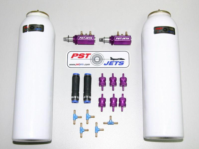
5 Proceed to unpack your kit. The parts list and photos of the main subassemblies are shown below. Please ensure that your kit is complete. If not notify your dealer immediately. Parts List Copyrights PST Jets Co., Ltd. Page 5 Version 1.0/2007
 from wing leading edge where the wing joins the fuselage with Gear down and empty fuel tank. This is exactly at the main fuselage former.")
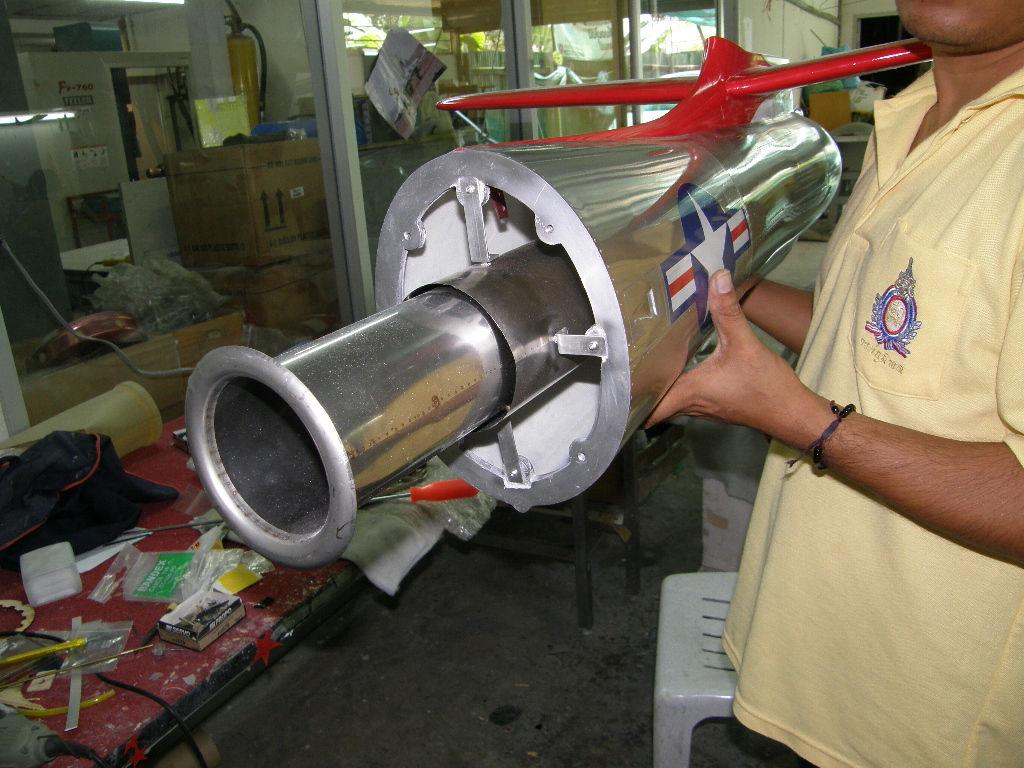
6 Specifications Scale 1/5.6 Wing Span 2.4 Meter (94 inches) with tip tanks Length 2.1 Meter (82 inches) CG mm (4.5-5inches) from wing leading edge where the wing joins the fuselage with Gear down and empty fuel tank. This is exactly at the main fuselage former. Control throws / Set up: Elevators: mm Up/Down (10-15mm Low rate; 15% Exp) - measured from fuselage & Stabilizer line Ailerons: mm Up/Down (10-15 mm Low rate; 15% Exp) - measured from wing tip with reference to flaps up Rudders: 20 mm L/R Flaps: Takeoff - 18 Degrees; Landing - 35 Degrees Nose Steering: 20 degrees left and right (a gyro may be used on the steering if you wish) Clearance between turbine tail cone (outer, large one) and pipe 20 mm Copyrights PST Jets Co., Ltd. Page 6 Version 1.0/2007


7 Wings Let s get started with the wings. We will show you the left wing, both wings are identical, and should be assembled in the same way. First, place the wing on a clean soft surface to avoid any damage. 1. We will start with the aileron and flaps. Locate the left aileron and left flap. Locate 6 hinge points. These will be used for the aileron and flap respectively. We recommend that you oil or grease the pin area to make sure that no glue penetrates the pivot joint. Test fit the hinges in the aileron and the flap, and dry assemble these to the trailing edge of the wing. If necessary clear any of the hinge slots and holes to allow for a full but snug fit. Make sure the flap and aileron move freely on the hinges. In the case of hinge points do no forget to keep the pivot point at a right angle to the control surface and to ensure that all pivot points are in line with each other. When satisfied with the fit, epoxy three point hinges (ailerons) and 3 point hinges (flaps) to the wing s trailing edge. Make sure the hinges are absolutely in line and pivot straight up and down. NOTE: Roughen the hinge surface to improve bonding strength, also remember that we are using 30 minute epoxy, do not cut corners and use faster curing epoxy. 2. Leave to cure. Make sure that no epoxy has run into the hinge joint, if it has, clean immediately with isopropyl alcohol. Aileron photos Copyrights PST Jets Co., Ltd. Page 7 Version 1.0/2007


8 Aileron link and cover in place inside wheel bay. Flap servo mounted inboard with linkage Copyrights PST Jets Co., Ltd. Page 8 Version 1.0/2007

9 control horn glued into milled slot on flap, ensure that the slot coming out of wing trailing edge is clear and allows full movement of the linkage. 3. After the hinges have cured, epoxy the hinges to the aileron and flap. Use masking tape to hold the control surface in position so that the hinges do not partially slide out. As mentioned above, make sure that no epoxy has run into the hinge point pivot joint. 4. Check alignment carefully. 5. Make sure that ailerons can move at least 25mm up/down and that flaps have at least 45 degrees downward movement. 6. Locate the aileron and flap linkage horns; we have pre-slotted the location of where the horns go on each control surface. 7. Mill a slot for each control horn; take care to ensure a neat clean fit. The control horn should extend from the slot as shown in the photo below 8. Generously epoxy the linkage horns to ailerons and flaps where marked. Make sure that L & R side aileron horns are standing up at equal height, and that the flap control horns extend equally. We cannot over emphasize how important it is that left and right linkages match each other. We use a 30 minute epoxy mixed with a small amount of milled fiber such as the BVM milled fiber glass. This gives a consistency similar to syrup and a stronger joint. Wipe off any excess epoxy that may come out of the slot, clean with alcohol as necessary. Let this assembly cure. 9. Locate the tip tank. Your tip tanks have alignment pins pre installed, and the tip rib of the wing has predrilled mating holes to accept the tip tank. 10. Dry fit the tip tank and make sure that it is aligned with the wing tip rib. Also make sure that the aileron assembly does not bind against the tip tank. If necessary enlarge the hold to adjust the fit of the tip tank. The angle of the tip tank should be a right angle to the wing. Copyrights PST Jets Co., Ltd. Page 9 Version 1.0/2007


10 11. Fasten the tip tanks with 8 screws provided in the hardware pack. 12. Locate the hatch covers for the aileron and flap servos. Locate two servo mounting brackets. 13. Mount the aileron servo mount brackets in the hatch as shown in the photo at the beginning of this section. Use 30 minute epoxy or slow zap to do this. 14. Linkages are external on the aileron and internal through the wheel bay on the flap. The flap servo is mounted in the wheel bay in a precut mount hole as shown in the accompanying photo at the beginning of this section. 15. Make sure that the control rods are 90 degrees with respect to the ailerons and flaps. The servo should be energized and set to center position. 16. With the Ailerons aligned with the tip tanks, make sure that the aileron servo horns are standing straight up with equal movement in both directions. Use servo horns that are long enough to get at least 25mm up/down movement on the control surface as measured from the neutral point against the tip tank. 17. With the Flaps fully retracted (aligned with aileron), make sure that the flap servo horns are pointing slightly toward the wing trailing edge thus allowing greater movement for flap extension. Again make sure you have energized the servo, and that it is in its neutral position when you mount the servo horn. The neutral position is important. Many computer radios have the full up position of the flap control in the servos neutral position. If you set the servo to the full in position you will have great difficulty adjusting it later. 18. Insert aileron servo lead extensions. (user provided) Make sure you have secured the joint on all lead extensions, we don t want them pulling out by accident. 19. Secure the aileron hatch cover with the provided screws. Copyrights PST Jets Co., Ltd. Page 10 Version 1.0/2007


11 Repeat the above steps for the right wing. Congratulations you have completed the wings. We will cover wing fitting to the fuse later in this manual. Copyrights PST Jets Co., Ltd. Page 11 Version 1.0/2007

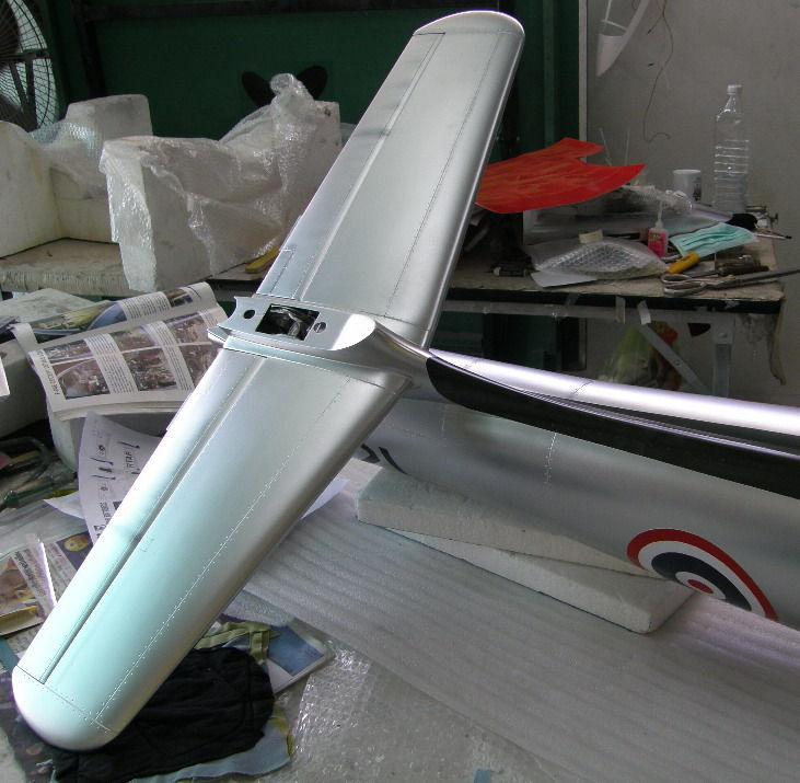
12 Let s move on to the tail section. 1. Locate the left and right stabilizers; each side is marked as left and right. Again put these on a clean soft surface to prevent damage and marking. 2. The stabilizer mounts to the fuse using a two wood spars, the slots have already been milled for you. The rear spar is slightly shorter than the front spar, do not mix the two spars up. 3. Dry fit the stabilizers and make sure that they line up correctly against the fillet extending from the fuselage. Your stabilizers were pre aligned at the factory, in the unlikely event that line up is not correct, use a Permagrit round file to slightly open the hole in the fuse slot to allow correct alignment. 4. When satisfied with your stabilizer alignment. To ensure a good bond, sand the stabilizer and fuselage joining surfaces slightly to remove paint and primer. 5. Smear a generous coat of 30 minute epoxy on the spars (you may slightly thicken this with milled fiberglass), coat the stab root surface and the fuse joining surface with 30 minute epoxy and insert the stabilizer spars and press the stabilizers in place. Pay attention and ensure that you have correctly placed the left and right sides as marked. Please be careful to cleanup any excess epoxy that comes out of the joint. 6. Check alignment and set aside for the epoxy to cure. You may wish to use masking tape to hold the stabilizer in place while it cures. 7. Locate the left and right elevators. 8. Each elevator has its own torque rod. 9. Disassemble the torque rod and insert the rod through the elevator and the fuselage while placing the horn in the position as described above and shown in the photos. (This is inside the rear of the fuselage). You will be using a single servo as shown in the photo below, we provide a Y shaped push rod that joins the two torque rods. Copyrights PST Jets Co., Ltd. Page 12 Version 1.0/2007


13 10. There are one 3 mm bolt on each side to secure the elevator horn to the torque rod. There is a mark on the rod for proper positioning of the set screws. 11. Secure all bolts and elevator inserts with thread lock. 12. Please note that you have not yet mounted the torque rod to the elevators. Y shaped push rod connected to torque rods. Copyrights PST Jets Co., Ltd. Page 13 Version 1.0/2007
14 13. The left and right elevators are marked. Locate 6 hinge points and insert 3 hinge points for each elevator. The elevators are predrilled to accept these hinge points. Grease the pivots on the hinge points to prevent glue from getting into the joint, then epoxy the hinge points in place in each elevator, make sure the hinges are at right angles to the control surface and are fully seated. The pivot points must all be in line with each other. 14. Glue the torque rod into each elevator half and let cure. Use 30 minute epoxy, rough up the torque rod surface with sand paper or a file to ensure good bonding. When the torque rod is cured, proceed to glue the hinges to the elevator and stab trailing edge and fit in place. 15. Check that the left and right elevators are aligned and move freely before the epoxy sets. Be careful not to get epoxy into the hinge joints or on the moving part of the torque rod. If necessary wipe away excess epoxy with isopropyl alcohol. 16. Locate your Y elevator push rod. We recommend that you mount the elevator servo now, and actuate and center the servo. With the servo arm in the neutral position you can properly align your elevator push rod arm. Place the elevator push rod on the horn with the provided bolt. 17. Finish securing the pushrod to the servo side. Center the servo horn and make sure the elevators can move at least 25 mm up and down. Copyrights PST Jets Co., Ltd. Page 14 Version 1.0/2007


15 Congratulations, you have finished the stabilizers and elevators. Copyrights PST Jets Co., Ltd. Page 15 Version 1.0/2007
16 Rudder We will now assemble and install the rudder.. 1. Locate the rudder and vertical fin assemblies, and place on a soft clean surface. 2. Locate 3 hinge points. 3. Test fit the rudder to the vertical fin with the hinge points in place. 4. When satisfied with the rudder vertical fin fit, epoxy the point hinges to the rudder. We recommend that you grease the hinge pivots to avoid glue getting in the joint. Pay attention to the direction of rotation of the rudder hinges. The pivot points must be at a right angle with the control surface. 5. Trial fit the rudder into position on the stab. Check for proper fit and alignment. 6. Epoxy the two control horns for the rudder pull pull system into the precut slots on the rudder. 7. When the control horns are cured, epoxy the point hinges to the stab using 30 minute epoxy, and let cure. As before grease the hinge points slightly, and be careful not to allow glue to enter the joint. 8. Mount the rudder servo in the preinstalled servo mount located at the bottom of the vertical fin. Copyrights PST Jets Co., Ltd. Page 16 Version 1.0/2007


17 9. Rig the pull pull wires as shown in the above and connect to the rudder. 10. The Vertical fin assembly has two joining rods preinstalled for attachment into the fuse. Copyrights PST Jets Co., Ltd. Page 17 Version 1.0/2007
18 11. Seat the Vertical fin in the aft fuse section and check fit. 12. Use two M3 bolts to fasten this assembly in place. The vertical fin and rudder assembly is now complete. Copyrights PST Jets Co., Ltd. Page 18 Version 1.0/2007


19 We have completed the descriptive manual up to this point. However, the following photos can help to elaborate and aid further construction until we finalized the manual. Sorry. Cockpit: Copyrights PST Jets Co., Ltd. Page 19 Version 1.0/2007
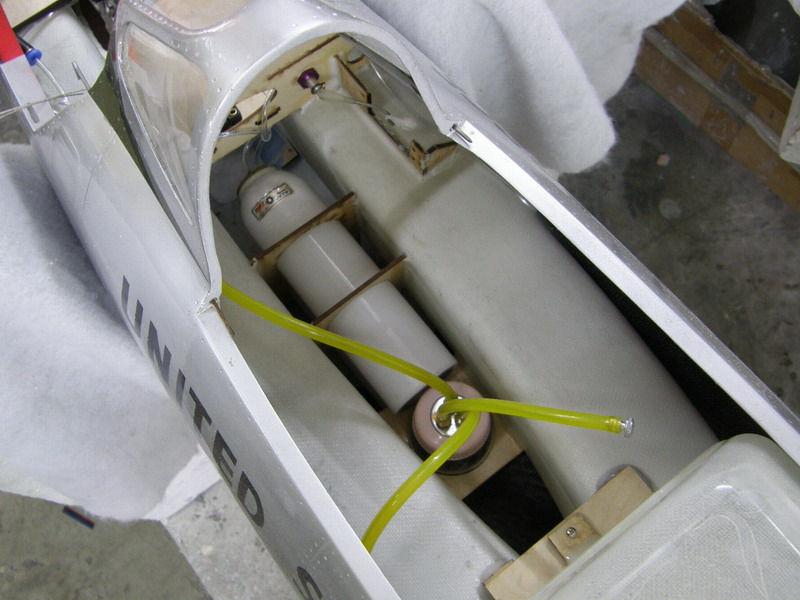
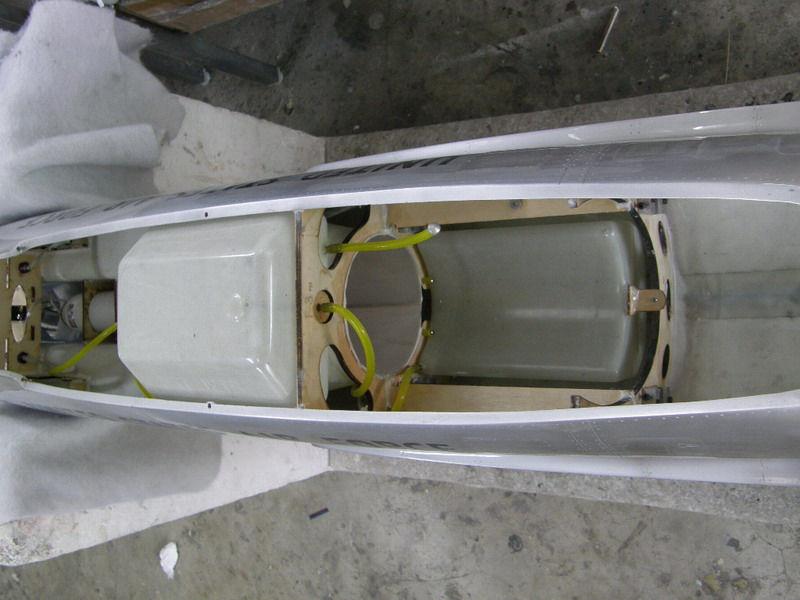
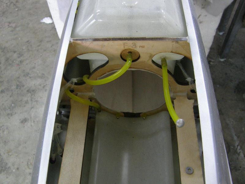
20 Fuselage: Copyrights PST Jets Co., Ltd. Page 20 Version 1.0/2007
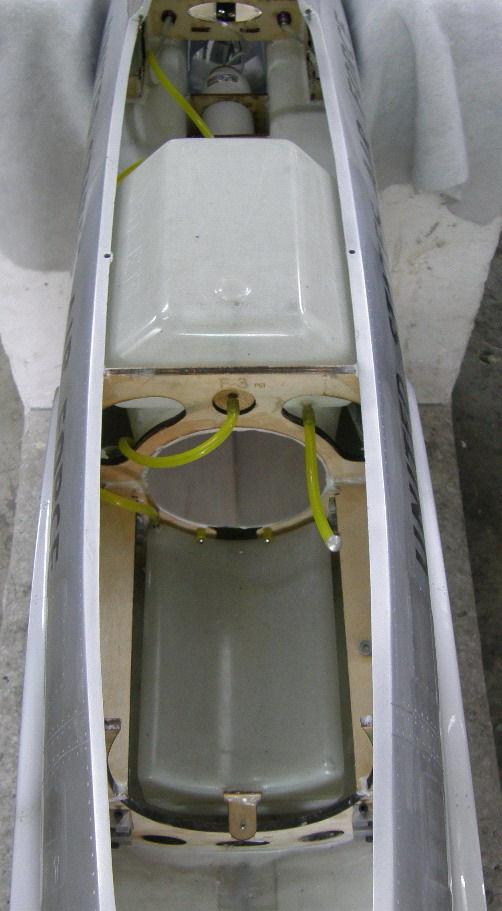

21 Copyrights PST Jets Co., Ltd. Page 21 Version 1.0/2007


22 Fuel Tank: Make sure that the fitting is secure all the way in with O-ring completely sealed inside and not just sitting on top. Copyrights PST Jets Co., Ltd. Page 22 Version 1.0/2007

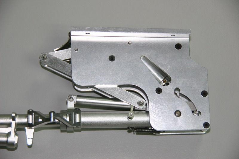

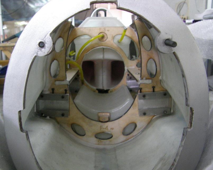
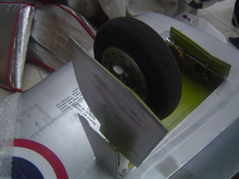
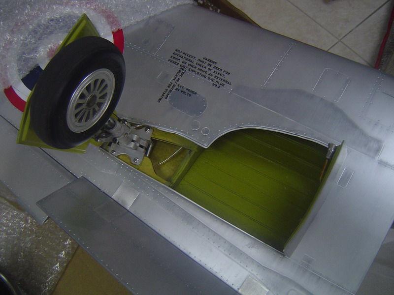
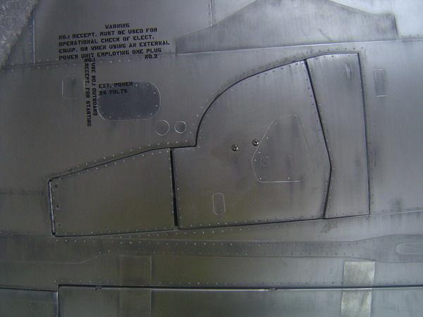
23 Landing Gear: Copyrights PST Jets Co., Ltd. Page 23 Version 1.0/2007

24 Copyrights PST Jets Co., Ltd. Page 24 Version 1.0/2007
Dassault Aviation FALCON 7 X. for Jet CAT P160. Assembly Manual. AVIATION Design
 Dassault Aviation FALCON 7 X for Jet CAT P160 Assembly Manual AVIATION Design ZI le chenet, 91490 Milly La Foret, FRANCE Tel : 33 1 64 98 93 93 Fax : 33 1 64 98 93 88 E-mail : aviation.design@wanadoo.fr
Turbinator-2 Build Manual
 Turbinator-2 Build Manual Thank you for your purchase of the Turbinator-2 sport jet by Boomerang RC Jets. This RC Jet IS NOT A TOY and should only be flown and operated by experienced RC Turbine Pilots.
Table of Contents. Tail Wheel Assembly Installation.. page 01. Stabilizer Installation.. page 02. Fin Installation.. page 03
 Table of Contents Tail Wheel Assembly Installation.. page 01 Stabilizer Installation.. page 02 Fin Installation.. page 03 Elevator and Rudder Hinge Installation.. page 04 Rudder Controls.. page 05 Elevator
ALMOST READY TO FLY. Wing Span in cm. 2
 ASSEMBLY MANUAL ALMOST READY TO FLY MS:X9 Specifications Wing Span --------------------------61.4 in ---------------------------156cm. 2 Wing Area --------------------------606.1 sq.in ------------------
Instruction Manual book
 book ITEM CODE:BH 115. SPECIFICATION Wingspan : 6,000 mm 236,22 in. Length : 2,740 mm 107,87 in. Weight : 17.5kg 38.5Lbs. Radio : 08 channels. Servo : 07-08 HS-5685MH(HITEC) Battery : 2 Cells-Li-Po 7.4V
(Glider) ASSEMBLY MANUAL
 ASSEMBLY MANUAL") (Glider) MS:132 ASSEMBLY MANUAL Graphics and specifications may change without notice. Specifications: Wing span ------------------------------118.1in (300cm). Wing area ---------------------902.1sq.in
(Glider) MS:132 ASSEMBLY MANUAL Graphics and specifications may change without notice. Specifications: Wing span ------------------------------118.1in (300cm). Wing area ---------------------902.1sq.in
ALMOST READY TO FLY. Wing Span in cm. 2
 ASSEMBLY MANUAL ALMOST READY TO FLY MS: X12 A - B Graphics and specfications may change without notice. Kit features. Specifications Wing Span ------------------------------- 42.7 in ---------------------
STORCH. Parts. Additional items needed to complete the Storch
 STORCH Parts Fuse with Greenhouse- (Attached) Left and right wing panel Horizontal and vertical stab 2 Wing center blocks 2 Carbon spares for wing 1 Undercarriage with wheels 2 Undercarriage shocks 2 Carbon
MS:176 ASSEMBLY MANUAL. Graphics and specifications may change without notice.
 ASSEMBLY MANUAL MS:176 Graphics and specifications may change without notice. Specifications: Wing span ------------------------------98.4in (250cm). Wing area ----------------1576.4sq.in (101.7sq dm).
Instruction Manual book
 book SPECIFICATION Wingspan : 1,450 mm 57.09 in. Length : 1,200mm 47.24in. Weight : 3.1 kg 6.82 Lbs. Radio : 05 channels. Servo : 07 servos. Engine : 61-75 2 stroke. 91 4 stroke. Made in Vietnam. This
MS:183 ASSEMBLY MANUAL. Graphics and specifications may change without notice.
 MS:183 ASSEMBLY MANUAL Graphics and specifications may change without notice. Specifications: Wing span ------------------------------79.9in (203cm). Wing area -----------------1165.6sq.in (75.2sq dm).
Instruction Manual book
 book SPECIFICATION Wingspan : 1,920 mm 75.59 in. Length : 1,560 mm 61.42 in. Weight : 5 kg 11.00Lbs. Radio : 06 channels. Servo : 09 servos. Engine : 120 4 stroke. Made in Vietnam. This instruction manual
Instruction Manual book
 Instruction Manual book SPECIFICATION Wingspan : 1,920 mm 75.59 in. Length : 1,560 mm 61.42 in. Weight : 5 kg 11.00Lbs. Radio : 06 channels. Servo : 09 servos. Engine : 120 4 stroke. Made in Vietnam. JU87-STUKA
Instruction Manual book
 Instruction Manual book SPECIFICATION Wingspan : 1,800mm. 70.87 in. Length : 1,350 mm. 53.15in. Weight : 3.6kg. 7.92lbs. Parts Listing required (not included). Glow Engine : 55-61 2 stroke. 91 4 stroke.
ASSEMBLY MANUAL. Graphics and specifications may change without notice.
 NEMESISMS: SEA 111 ASSEMBLY MANUAL Graphics and specifications may change without notice. Specifications Wing span------------------------------------- 55.9in ------------------------------- 142cm. Wing
Instruction Manual book
 Instruction Manual book SPECIFICATION Wingspan : 1,920 mm 75.59 in. Length : 1,560 mm 61.42 in. Weight : 5 kg 11.00Lbs. Radio : 06 channels. Servo : 09 servos. Engine : 120 4 stroke. Made in Vietnam. JU87-STUKA
MS:136 ASSEMBLY MANUAL. Graphics and specifications may change without notice.
 ASSEMBLY MANUAL MS:136 Graphics and specifications may change without notice. Specifications: Wing span ----------------------------79.5in (202cm). Wing area -----------------965.7sq.in (62.3sq dm). Weight
ARF TRAINER KIT ASSEMBLY MANUAL BOOMERANG EP. ALMOST READY TO FLY
 WWW.SEAGULLMODELS.COM ASSEMBLY MANUAL BOOMERANG EP ARF TRAINER KIT Graphics and specifications may change without notice. MS: 211 ALMOST READY TO FLY Specifications: Wingspan---------------56.0 in (142.2
INSTRUCTION MANUAL BOOK
 INSTRUCTION MANUAL BOOK ITEM CODE BH57. SPECIFICATION Wingspan: 1,470 mm. 57.87 in. Length : 1,180 mm. 46.46 in. Weight : 2.7 Kg. 5.94 Lbs. Engine : 46 cu.in 2 stroke. 52 cu.in 4 stroke. Radio : 4 channels.
Assembly Manual. Version 01/01/2006
 Assembly Manual ZI le chenet, 91490 Milly La Foret, FRANCE Tel : 33 1 64 98 93 93 Fax : 33 1 64 98 93 88 E-mail : aviation.design@wanadoo.fr www.adjets.com Version 01/01/2006 INTRODUCTION is our new jet
Instruction Manual book
 Instruction Manual book ITEM CODE:BH118. SPECIFICATION Wingspan : 1,050 mm 41.34 inches. Length : 950mm 37.4 inches. Weight : 1 kg 2.2 lbs. Radio : 04 channels. Servo : 4 mini servos. Motor : KMS 2814/05
MiG-29 Retract Kit (for the HET-RC Mini Air Retract System)
") MiG-29 Retract Kit (for the HET-RC Mini Air Retract System) The MiG-29 Retract Kit was designed to allow the easy installation of the HET-RC mini Air Retract system into the twin EDF MiG-29. We recommend
MiG-29 Retract Kit (for the HET-RC Mini Air Retract System) The MiG-29 Retract Kit was designed to allow the easy installation of the HET-RC mini Air Retract system into the twin EDF MiG-29. We recommend
MS:159 ASSEMBLY MANUAL. Graphics and specifications may change without notice.
 ASSEMBLY MANUAL MS:159 Graphics and specifications may change without notice. Specifications: Wing span ----------------------------61.8in (157cm). Wing area -----------------1100.5sq.in (71.0sq dm). Weight
Instruction Manual book
 book Item code:bh131 SPECIFICATION Wingspan : 3,000 mm 118.1 in. Length : 1,600 mm 62.99 in. Weight : 2.2 kg 4.84 Lbs. Radio : 05 channels. Servo : 06 mini servos. Electric Motor: BOOST 40 Battery : 3celIs
Instruction Manual book
 Instruction Manual book Item code:bh133 SPECIFICATION Wingspan : 1,400 mm 55.12 in. Length : 1,350 mm 53.15 in. Weight : 3.7 kg 8.14 Lbs. Radio : 08-09 channels. Servo : 08-09 servos. EDF : Turingy SK3
EXTRA 330LX. Specifications: Code: SEA274. Graphics and specifications may change without notice. ASSEMBLY MANUAL
 ASSEMBLY MANUAL EXTRA 330LX Code: SEA274 Graphics and specifications may change without notice. Specifications: Wingspan---------------82.0 in (208.2 cm). Wing area---------------1349.4 sq.in ( 87.1 sq.dm).
ASSEMBLY MANUAL. Kit features. MS:110
 MS:110 ASSEMBLY MANUAL Graphics and specifications may change without notice. Specifications: Wing span-------------------------------------------------- 62.9 in---------------------------------------
ASSEMBLY MANUAL
 www.seagullmodels.com MS: X104 ASSEMBLY MANUAL Graphics and specifications may change without notice. Specifications: Wing span ----------------- 35.4in (90.0cm). Wing area ------------------392.2sq.in
Instruction Manual book
 Instruction Manual book ITEM CODE:BH118. SPECIFICATION Wingspan : 1,050 mm 41.34 inches. Length : 950mm 37.4 inches. Weight : 1 kg 2.2 lbs. Radio : 04 channels. Servo : 4 mini servos. Motor : BL2215/20
MS:124 ASSEMBLY MANUAL. Graphics and specifications may change without notice.
 ASSEMBLY MANUAL MS:124 Graphics and specifications may change without notice. Specifications: Wing span ------------------------------65in (165cm). Wing area -----------------658.8sq.in (42.5sq dm). Weight
VENTRIX. Dear Customer, Thank you for purchase our Ventrix Sport jet product
 VENTRIX Dear Customer, Thank you for purchase our Ventrix Sport jet product Following you can find greater information for build and fly this model. Before you get started building and setting-up your
STICK F Class 60 Class INSTRUCTION MANUAL. Or Electric equivalent. (2T engine) (4T engine) Radio control model SPECIFICATIONS
 (4T engine) Radio control model SPECIFICATIONS") Radio control model 45 Class 60 Class (2T engine) (4T engine) Or Electric equivalent INSTRUCTION MANUAL STICK F - 1500 SPECIFICATIONS Wingspan 60 in. Length 38.5 in. Electric Motor 650 Watt Glow Engine.45
Radio control model 45 Class 60 Class (2T engine) (4T engine) Or Electric equivalent INSTRUCTION MANUAL STICK F - 1500 SPECIFICATIONS Wingspan 60 in. Length 38.5 in. Electric Motor 650 Watt Glow Engine.45
Instruction Manual book
 book ITEM CODE:BH 145 SPECIFICATION Wingspan: 6,000mm 236.22 in. Length : 2,800 mm 110.24 in. Weight : 18.5 kg 40.7 Lbs. Parts listing required (not included). Radio : 07-08 channels. Servo : 09-10 standard
PilotRC Trainer USER MANUAL
 PilotRC Trainer USER MANUAL Introduction Thank you for purchasing our Trainer plane. we strive to achieve a good quality quick build ARF aircraft. It requires the least amount of assembly of any ARF kit
MEMO. No.4341 Specification: Wing Span: 29.1 (740mm) Length: 36.6 (930mm) 2. Warranty
 Length: 36.6 (930mm) 2. Warranty") MEMO No.4341 Specification: Wing Span: 29.1 (740mm) Length: 36.6 (930mm) 2 Wing Area: 299 sq.in. (19.29 dm ) Weight: 18.9oz. (536.5g) 2 Wing loading: 0.58 oz./sq.ft (27.8g/dm ) Motor: OBL 29/27-07A Warranty
MEMO No.4341 Specification: Wing Span: 29.1 (740mm) Length: 36.6 (930mm) 2 Wing Area: 299 sq.in. (19.29 dm ) Weight: 18.9oz. (536.5g) 2 Wing loading: 0.58 oz./sq.ft (27.8g/dm ) Motor: OBL 29/27-07A Warranty
MARACANA ASSEMBLY INSTRUCTION .40 ARF LOW WING TRAINER RADIO CONTROL MODEL. Every body can fly
 RADIO CONTROL MODEL ASSEMBLY INSTRUCTION MARACANA.40 ARF LOW WING TRAINER Every body can fly VQA085 EP GP You can use both Gas or Electric power Wingspan: 59in.(1520mm) Fuselage length: 48in.(1220mm) Engine:
ARF. Specifications: ASSEMBLY MANUAL MS: 193. Graphics and specifications may change without notice.
 ASSEMBLY MANUAL Graphics and specifications may change without notice. MS: 193 ARF Specifications: Wingspan---------------62.0 in (157.5 cm). Wing area----------------620 sq.in (40.0 sq.dm). Weight-------------------3.3-3.9
CAP 232 ASSEMBLY MANUAL
 CAP 232 MS: ASSEMBLY MANUAL SEA 91 Graphics and specfications may change without notice. Specifications Wingspan------------------------------------ 65 in --------------------------------- 165cm. Wing
Assembly and Operating Manual. SPECIFICATION Length inch (640mm) Wing Span inch (705mm) Flying Weight oz (330g)
 Wing Span inch (705mm) Flying Weight oz (330g)") Assembly and Operating Manual SPECIFICATION Length 25.19 inch (640mm) Wing Span 27.76 inch (705mm) Flying Weight 11.64 oz (330g) Dear customer, Assembly and Operating manual VIPER The Radio Control System
Assembly and Operating Manual SPECIFICATION Length 25.19 inch (640mm) Wing Span 27.76 inch (705mm) Flying Weight 11.64 oz (330g) Dear customer, Assembly and Operating manual VIPER The Radio Control System
RADIO CONTROL MODEL HURRICANE
 RADIO CONTROL MODEL VQAA040G VQAA040B HURRINE Almost ready to fly SPECIFITIONS Wingspan...63 in. / 161cm Length...50 in. / 129cm Engine...50~60 2T / 70~90 4T Or Electric equivalent. RC Functions: Motor
Instruction Manual book
 Instruction Manual book ITEM CODE:BH135 SPECIFICATION Wingspan : 4,200mm. 163.35 in. Length : 2,100 mm. 82.68 in. Weight : 7,6 kg. 16.72lbs Radio : 07 channels. Servo : 05 06 standard high torque servos,
MS:160 ASSEMBLY MANUAL. Graphics and specifications may change without notice.
 MS:160 ASSEMBLY MANUAL Graphics and specifications may change without notice. Specifications: Wing span ------------------------------70.9in (180cm). Wing area -----------------613.8sq.in (39.6sq dm).
I n s t r u c t i o n M a n u a l. Instruction Manual SPECIFICATION
 I n s t r u c t i o n M a n u a l Instruction Manual SPECIFICATION - Wingspan: 3200mm (125,9 in) - Length: 1650mm (64,9 in) - Flying weight: 3000gr 3200gr - Wing area: 64.5 dm2 - Wing loading: 46g/dm2
51in Aerobatic Series Sukhoi SU-26M Almost-Ready-to-Fly. Instruction Manual. Specifications
 51in Aerobatic Series Sukhoi SU-26M Almost-Ready-to-Fly Instruction Manual Specifications Wingspan: 51.2 in (1300mm) Length: 51.2 in (1300mm) Wing Area: 581 sq in (37.5sq dm) Flying Weight: 3.5 lb (1600g)
Instruction Manual book
 Instruction Manual book SPECIFICATION Wingspan : 2,170 mm 85.43 in. Length : 1,760 mm 69.29 in. Weight : 6.3 kg 13.86 Lbs. Radio : 06 channels. Servo : 08 servos. Engine : 45-50CC Gas. Made in Vietnam.
MS:174 ASSEMBLY MANUAL. Graphics and specifications may change without notice.
 MS:174 ASSEMBLY MANUAL Graphics and specifications may change without notice. Specifications: Wing span ------------------------------79.9in (203cm). Wing area -----------------911.4sq.in (58.8sq dm).
Instruction Manual book
 book ITEM CODE:BH 139 SPECIFICATION Wingspan : 1,450mm 57.09 in. Length : 1,140 mm 44.88 in. Weight : 3.3kg 7.26 Lbs. Radio : 05 channels. Servo : 07 mini servos+ 3servos Retracts (FUTABA S3170G) EDF:
Instruction Manual book
 Instruction Manual book Item code:bh144 SPECIFICATION Wingspan : 1,400 mm 55.12 in. Length : 1,350 mm 53.15 in. Weight : 4 kg 8.8 Lbs. Empty Weight: 1.9 kg 4.18 lbs Radio : 08 channels. Servo : 08 size
ASSEMBLY MANUAL. Specifications
 ASSEMBLY MANUAL MS: SEA 82 Graphics and specfications may change without notice. Specifications Wingspan-------------------------------------- 70.9 in------------------------------ 180cm. Wing area-------------------------------------
SIZE 55 ASSEMBLY MANUAL
 SIZE 55 ASSEMBLY MANUAL MS:120 Graphics and specifications may change without notice. Specifications: Wing span ------------------------------63in (160cm). Wing area -----------------643.3sq.in (41.5sq
ASSEMBLY MANUAL SIZE
 SIZE.75 -.91 ASSEMBLY MANUAL MS:123 Graphics and specifications may change without notice. Specifications: Wing span ----------------------------66.9in (170cm). Wing area -----------------761.1sq.in (49.1sq
ASSEMBLY MANUAL. Kit features. MS:76
 ASSEMBLY MANUAL MS:76 Graphics and specfications may change without notice. Specifications: Wingspan---------------------------------------------------- 82.8 in------------------------------------- 210.3cm.
Assembly Manual For. Wingspan: 88 in Wing area: sp in Length: 78.8 in Engine: 50CC.
 Assembly Manual For Wingspan: 88 in Wing area: 1479.8 sp in Length: 78.8 in Engine: 50CC www.pilot-rc.com INTRODUCTION Thank you for purchasing our new 50 cc model. We strive to bring you the most complete
YAK 54 Aerobatic Model Aircraft Assembly and Instruction Manual
 YAK 54 Aerobatic Model Aircraft Assembly and Instruction Manual Warning: This radio controlled model is not a toy. It requires skill to fly and is not recommended for the novice pilot. It should not be
to fly. Most hardware included and all replacement parts are available.
 Instruction Manual The Thunderbolt P47 was perhaps the greatest of world war II in terms of all round performance and capability Phoenix Model has recreated a 2C - 60 class engine (or 4c 91 class) It was
MESSERSCHMITT. - Bf 109E 60. Specifications: Code: SEA278. Graphics and specifications may change without notice. ASSEMBLY MANUAL
 ASSEMBLY MANUAL MESSERSCHMITT - Bf 109E 60 Graphics and specifications may change without notice. Code: SEA278 Specifications: Wingspan---------------64.0 in (163 cm). Wing area---------------765.7 sq.in
RECOMMENDED MOTOR AND BATTERY SET UP
 SPECIFICATION - Wingspan: 1404mm (55.3in) - Length: 1134mm (44. 6 in) - Flying weight: 3.2-3.4 kg - Covering type: Genuine ORACOVER - Spinner size: scale type (not included) - Radio: 4 channel minimum
Instruction Manual book
 book SPECIFICATION Wingspan : 2,310 mm 90.94 in. Length : 1,750 mm 68.90 in. Weight : 8.4 kg 18.48 Lbs. Radio : 06 channels. Servo : 09 servos + 2 mini servos (elevator). Engine : 45-55CC gas. Made in
Instruction Manual book
 Instruction Manual book SPECIFICATION Wingspan : 1,780 mm 70.08 in. Length : 1,520 mm 59.84 in. Weight : 4.8 kg 10.56 Lbs. Radio : 06 channels. Servo : 09 servos. Engine : 120 4stroke Made in Vietnam.
RECOMMENDED MOTOR AND BATTERY SET UP
 SPECIFICATION - Wingspan: 1410mm (55.5 in) - Length: 1278mm (50.3 in) - Flying weight: 3.2-3.4 kg - Wing area: 41.3 dm2 - Wing loading: 75g/dm2 - Wing type: Naca airfoils - Covering type: Genuine ORACOVER
Trainer Assembly Manual
 Trainer Assembly Manual www.pilot-rc.com -Pilot Trainer- 1 -Pilot Trainer- 2 -Pilot Trainer- 3 -Preliminary i wing & stab assembly- 1-) Locate both Plywood wing joiners (Large and small one) 2-) Insert
LASER 200. Hand-made Almost Ready to Fly R/C Model Aircraft ASSEMBLY MANUAL
 LASER 200 Hand-made Almost Ready to Fly R/C Model Aircraft ASSEMBLY MANUAL SPECIFICATIONS: WING SPAN ----------------------------------------175CM -------------------------------- 68.75 in. WING AREA ------------------------------------------4746CM2
RADIO CONTROL MODEL ASSEMBLY INSTRUCTIONS. Wasp
 RADIO CONTROL MODEL ASSEMBLY INSTRUCTIONS Wasp TRAINER Almost ready-to-fly Wingspan 1520mm Fuselage length 1105mm Engine: 40-46 2T / 52-60 4T Electric Motor: 600-700W Radio: 5 channel / 4-5 servo RC Functions:
RECOMMENDED MOTOR AND BATTERY SET UP
 SPECIFICATION - Wingspan: 6000mm (236.2 in) - Length: 2873mm (113.1 in) - Flying weight: 14-18 kg - Wing area: 219.4 dm2 - Wing loading: 64g/dm2 - Wing type: HQ airfoils - Covering type: Genuine ORACOVER
第 4 页. 3. Fix the fiber horns to the slots in the aileron with epoxy glue. Accessory list for the installation of aileron.
 TopRCModel-USA.com TopRCModel-USA.com 第 3 页 Accessory list for the installation of aileron. 3. Fix the fiber horns to the slots in the aileron with epoxy glue. 1. Sanding the fiber horns. 4. Fix the fiber
Instruction Manual book
 Instruction Manual book Item code:bh117 SPECIFICATION Wingspan : 2,100 mm 82.68 in. Length : 1,875 mm 73.82 in. Weight : 7.5 kg 16.5 Lbs. Radio : 08 channels. Servo : 09 servos. Engine : 33-45cc gas. Made
FUN-50 ARF ASSEMBLY MANUAL
 FUN-50 ARF ASSEMBLY MANUAL This Manuel is the sole property of Kangke Industrial USA, Inc. Reproducing any part without the consent of Kangke Industrial USA, Inc. is a lawful violation. Kangke Industrial
Please read all instructions carefully before assembly and flight!
 Please read all instructions carefully before assembly and flight! Thank you for purchasing the Mig-15. This model is designed for the intermediate to advanced flyer. The model is receiver ready and includes
Lanier R/C F-4 Phantom
 Lanier R/C.40-.46 F-4 Phantom Almost Ready to Fly WARNING! THIS IS NOT A TOY! THIS IS NOT A BEGINNERS AIRPLANE This R/C kit and the model you will build from it is not a toy! It is capable of serious bodily
Instruction Manual book
 Instruction Manual book Item code:bh117 SPECIFICATION Wingspan : 2,100 mm 82.68 in. Length : 1,875 mm 73.82 in. Weight : 7.5 kg 16.5 Lbs. Parts listing required (not included) Radio : 08 channels. Servo
Specifications: Code: SEA305. Graphics and specifications may change without notice. ASSEMBLY MANUAL P-26A PEASHOOTER
 ASSEMBLY MANUAL P-26A PEASHOOTER Code: SEA305 Graphics and specifications may change without notice. Specifications: Wingspan---------------71 in (180 cm). Wing area---------------965.7 sq.in ( 62.3 sq.dm).
ASSEMBLY MANUAL. Specifications
 ASSEMBLY MANUAL MS: SEA 82 Graphics and specfications may change without notice. Specifications Wingspan-------------------------------------- 70.9 in------------------------------ 180cm. Wing area-------------------------------------
Instruction Manual book
 book SPECIFICATION Wingspan : 2,080 mm 81.89 in. Length : 1,680 mm 66.14 in. Weight : 6.2 kg 13.64 Lbs. Radio : 06 channels. Servo : 06 servos. Engine : 30-35 CC Gas(FUJI IMVAC). Made in Vietnam. This
Supplemental Instructions for Walkera F-16
 Supplemental Instructions for Walkera F-16 Step 1 the instructions show a brushed motor setup and indicate you should solder 3 capacitors to the motor terminals. The kit actually contains a brushless motor,
Instruction Manual book
 book ITEM CODE: BH109 SPECIFICATION Wingspan : 2,200mm. 86.61 in. Length : 1,976 mm. 77.80in. Weight : 8.3 kg. 18.26 lbs. Part listing required (not included) Glow Engine : 55 CC Gas Servo : 9 servos.
Instruction Manual book
 book (pusher propeller) ITEM CODE:BH 142 SPECIFICATION Wingspan : 1,450mm 57.09 in. Length : 1,165 mm 45.87 in. Weight : 3.3kg 7.26 Lbs. Radio : 05 channels. Servo : 07 size (29 x 13 x 30) mm. Electric
YAK-54 EXP. 48 inch Electric ARF
 YAK-54 EXP 48 inch Electric ARF 1 Greetings and congratulations on your purchase of the Extreme Flight RC Yak-54 EXP ARF! Like all of the EXP series, the YAK-54 excels at both 3D and precision maneuvers.
1660mm (65.4 in) 1200mm (47.2 in) 2700gr gr 6 channel - 7 servo standard 46/ 2 stroke or 52/ 4 stroke
 1200mm (47.2 in) 2700gr gr 6 channel - 7 servo standard 46/ 2 stroke or 52/ 4 stroke") Instruction Manual CESSNA-46 1660mm (65.4 in) 1200mm (47.2 in) 2700gr - 3000gr 6 channel - 7 servo standard 46/ 2 stroke or 52/ 4 stroke KIT CONTENTS: We have organized the parts as they come out of the
Instruction Manual CESSNA-46 1660mm (65.4 in) 1200mm (47.2 in) 2700gr - 3000gr 6 channel - 7 servo standard 46/ 2 stroke or 52/ 4 stroke KIT CONTENTS: We have organized the parts as they come out of the
Gent EPP. Before use please read the explanations carefully
 Before use please read the explanations carefully Gent EPP Instruction Manual Specifications Fuselage length 900mm 35in Wingspan 820mm 32in Flying Weight 210 240g with battery Additional Required Equipment
Instruction Manual. Wingspan : 1694mm (66.69 in) : 1470mm (57.87 in) : 3200gr gr. : 61 two stroke/ 71 four stroke. : 6 channel / 7 servo
 : 1470mm (57.87 in) : 3200gr gr. : 61 two stroke/ 71 four stroke. : 6 channel / 7 servo") Wingspan : 1694mm (66.69 in) g Length : 1470mm (57.87 in) Weight : 3200gr - 3800gr Engine : 61 two stroke/ 71 four stroke Radio : 6 channel / 7 servo KIT CONTENTS: We have organized the parts as they
Wingspan : 1694mm (66.69 in) g Length : 1470mm (57.87 in) Weight : 3200gr - 3800gr Engine : 61 two stroke/ 71 four stroke Radio : 6 channel / 7 servo KIT CONTENTS: We have organized the parts as they
RACER DELTA Specifications: Code: SEA307. Graphics and specifications may change without notice. ASSEMBLY MANUAL
 ASSEMBLY MANUAL RACER DELTA 40-46 Code: SEA307 Graphics and specifications may change without notice. Specifications: Wingspan---------------39.0 in (98.5 cm). Wing area---------------641.1 sq.in ( 41.4
Instruction Manual book
 Instruction Manual book ITEM CODE:BH 140 SPECIFICATION Wingspan : 2,050mm 80.71 in. Length : 1,840 mm 72.41 in. Weight : 6.8kg 14.96 Lbs. Radio : 07 channels. Servo : 09 servos. Engine: O.S GT 33 CC gas.
MAXI LIFT. 33cc ASSEMBLY MANUAL. ALMOST READY TO FLY. Specifications: MS: 209
 WWWSEAGULLMODELSCOM ASSEMBLY MANUAL MAXI LIFT 33cc Graphics and specifications may change without notice MS: 209 ALMOST READY TO FLY Specifications: Wingspan---------------876 in (2222 cm) Wing area----------------10726sqin
SBACH SCALE 1:4 ½ ARF
 SPECIFICATION - Wingspan: 1663mm (65.5 in) - Length: 1638mm (64.5 in) - Flying weight: 4700-5200 gr - Wing area: 56 dm2 - Wing loading: 85g/dm2 - Wing type: Naca airfoils - Covering type: Genuine ORACOVER
SIZE.120 OR 30CC SCALE 1:5 ARF
 PC21 PILATUS MK2 SIZE.120 OR 30CC SCALE 1:5 ARF SPECIFICATION - Wingspan: 1772mm (69.72in) - Length: 2019mm (79.5 in) - Flying weight: 6.4-7.2 kg - Wing area: 57.6 dm2 - Wing loading: 113g/dm2 - Wing type:
Instruction Manual. Wingspan : 1884 mm (74.17 in) Length. Weight. Engine. : 4 channels / 5 servo standard. : 1450 mm (57.
 Length. Weight. Engine. : 4 channels / 5 servo standard. : 1450 mm (57.") Wingspan : 1884 mm (74.17 in) Length : 1450 mm (57.09 in) Weight : 4000 gr Engine : 60 two strokes Radio : 4 channels / 5 servo standard KIT CONTENTS: We have organized the parts as they come out of the
Wingspan : 1884 mm (74.17 in) Length : 1450 mm (57.09 in) Weight : 4000 gr Engine : 60 two strokes Radio : 4 channels / 5 servo standard KIT CONTENTS: We have organized the parts as they come out of the
RECOMMENDED MOTOR AND BATTERY SET UP
 SPECIFICATION - Wingspan: 1800mm (70.8 in) - Length: 1355mm (53.3 in) - Flying weight: 4100-4300 g - Wing area: 51 dm2 - Wing loading: 80g/dm2 - Wing type: Naca airfoils - Covering type: Genuine ORACOVER
 WWW.SEAGULLMODELS.COM ASSEMBLY MANUAL Graphics and specifications may change without notice. Code: SEA231 Specifications: Wingspan---------------80 in (203.2 cm). Wing area---------------1235.4 sq.in (79.7
 WWW.SEAGULLMODELS.COM ASSEMBLY MANUAL Graphics and specifications may change without notice. Code: SEA240 (SEA240M) (SEA240Y) Specifications: www.seagullmodels.com Wingspan---------------74.8 in (190 cm).
I/C FLIGHT GUIDELINES
 SPECIFICATION - Wingspan: 3500mm (137.8 in) - Length: 1650mm (64.96 in) - Flying weight: 3700-4000 gr - Wing area: 75 dm2 - Wing loading: 49g/dm2 - Wing type: HQ profile - Covering type: Genuine ORACOVER
 WWW.SEAGULLMODELS.COM ASSEMBLY MANUAL Graphics and specifications may change without notice. Code: SEA232 Specifications: Wingspan---------------70.9 in (180 cm). Wing area---------------810.3 sq.in (52.3
Assembly and Operating Manual HR-100. Specification: *Length: 41-7/10"(1060 mm) *Wing span: 49-1/5"(1250 mm) *Flying weight: 45.
 *Wing span: 49-1/5(1250 mm) *Flying weight: 45.") Assembly and Operating Manual HR-100 Specification: *Length: 41-7/10"(1060 mm) *Wing span: 49-1/5"(1250 mm) *Flying weight: 45.9 oz (1300g) Dear customer, Congratulations on your choice of a factory-assembled
Assembly and Operating Manual HR-100 Specification: *Length: 41-7/10"(1060 mm) *Wing span: 49-1/5"(1250 mm) *Flying weight: 45.9 oz (1300g) Dear customer, Congratulations on your choice of a factory-assembled
F3P Instruction Manual
 Before use, please read the explanations carefully! F3P Instruction Manual Specifications Fuselage length: 884mm ( 34. Bin ) Wingspan : 845mm ( 33. 2in) Flying Weight : 135-160g (with battery) Additional
SK-50 ARF ASSEMBLY MANUAL
 SK-50 ARF ASSEMBLY MANUAL Kangke Industrial USA, Inc. 65 East Jefryn Blvd. Deer Park NY 11729 http://www.kangkeusa.com E-mail: info@kangkeusa.com Tel: 1-877-203-2377 Fax: 1-631-274-3296 Congratulations!
WE GET PEOPLE FLYING T-34
 TM WE GET PEOPLE FLYING T-34 Mentor ASSEMBLY MANUAL Specifications Wingspan:... 57.25 in (1454 mm) Length:... 45 in (1146 mm) Wing Area:... 555 sq in (35.8 sq dm) Weight:... 6 7 lb (2.7 kg 3.2 kg) Radio:...
 WWW.SEAGULLMODELS.COM A S S E M B L Y M A N U A L Graphics and specifications may change without notice. Code : SEA255 Specifications: www.seagullmodels.com Wingspan---------------70.9 in (180 cm). Wing
96in Super Decathlon ARF
 96in Super Decathlon ARF Instruction Manual Specifications Wingspan: 96in (2438mm) Length: 63.5 in (1614mm) Weight: Approx. 13lbs (6.5kg) 1 Dear Customer, Congratulations on your purchase of Super Decathlon
ASSEMBLY MANUAL. Specifications
 MS:56H Kit features. Specifications Wingspan ------------------------------ 63 in -------------------------- 160cm. Wing area ----------------------------- 728 sq.in ------------------ 47 sq.dm. Weight
Instruction Manual. Specification:
 Instruction Manual L O W Specification: Wingspan: 133 cm (52.3 inches) Length : 104 cm (40.9 inches) Weight : 1790gr Engine : 25-32 two stroke Radio : 4 channel - 4 servo W I N G KIT CONTENTS: We have
Instruction Manual. Wingspan : 1670mm. : 3400gr gr. : 61/75 two stroke. : 5 servo + 1 servo retract / 6 channel
 Wingspan : 1670mm g Length Weight Engine Radio : 1350mm : 3400gr - 4000gr : 61/75 two stroke : 5 servo + 1 servo retract / 6 channel KIT CONTENTS: We have organized the parts as they come out of the box