RECOMMENDED MOTOR AND BATTERY SET UP
|
|
|
- Virgil Manning
- 5 years ago
- Views:
Transcription


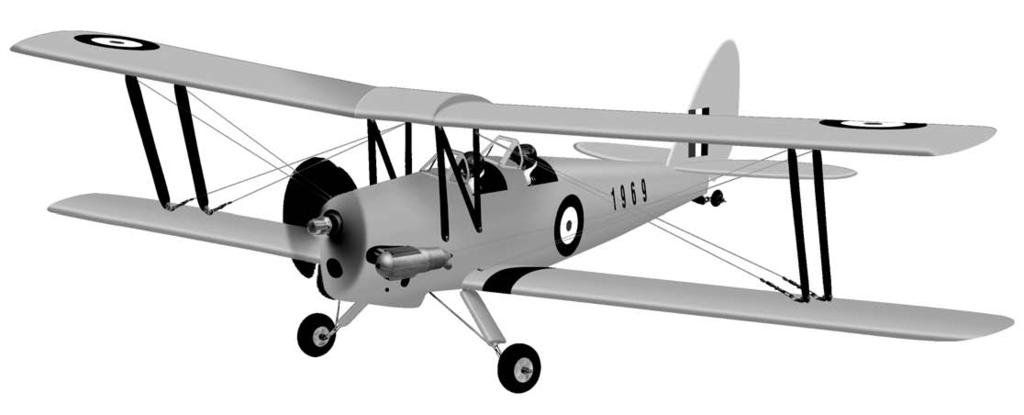


1 SPECIFICATION - Wingspan: 1404mm (55.3in) - Length: 1134mm (44. 6 in) - Flying weight: kg - Covering type: Genuine ORACOVER - Spinner size: scale type (not included) - Radio: 4 channel minimum (not included) - Servo: 2 aileron; 1 elevator; 1 rudder; 1 throttle (not included) - Recommended receiver battery: 4.8-6V / mAh NiMH (not included) - Propeller: suit with your engine - Engine: / 2-stroke or.52/4-stroke glow engine (not included) - Motor: brushless outrunner W, 480 KV (not included) - Gravity CG: 90 mm (3.5 in) Back from the leading edge of the upper wing, at the fuselage - Control throw Ailerons: Low: 10mm up/down, 10% expo; High: 12mm up/down, 10% expo - Control throw Elevators: Low: 8mm up/down, 12% expo; High: 10mm up/down, 12% expo - Control throw Rudder: Low: 25mm right/left, 15% expo; High: 40mm right/left, 15% expo - Experience level: Intermediate - Plane type: Scale Civilian RECOMMENDED MOTOR AND BATTERY SET UP - Motor: RIMFIRE (not included) - Lipo cell: 6 cells / mAh (not included) - Esc: 50-70A (not included)
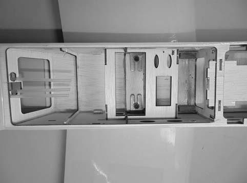
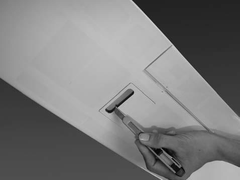
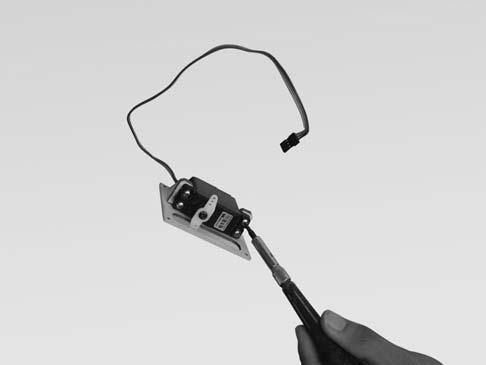
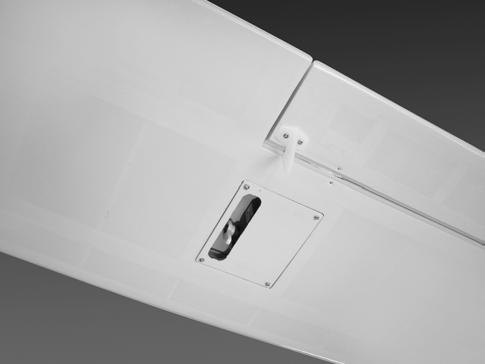
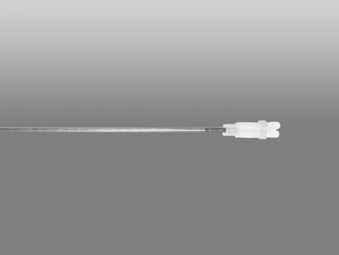
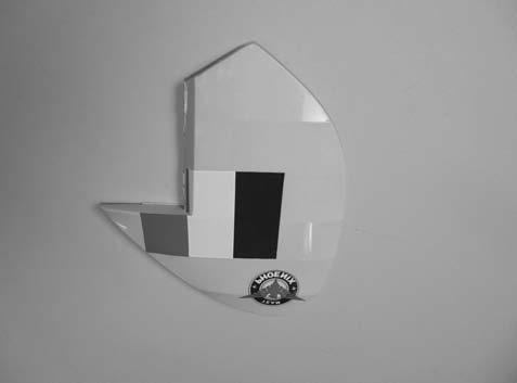
2 TOOLS AND SUPPLIES NEEDED. INSTALLING THE AILERON SERVOS Medium C/A glue. 30 minute epoxy. 6 minute epoxy. Hand or electric drill. Assorted drill bits. Modeling knife. Straight edge ruler. 2 bender plier. Wire cutters. Masking tape. Thread lock. Paper towels. Rubbing alcohol 1. Install the rubber grommets and brass eyelets onto the aileron servo. 2. Using a modeling knife, remove the covering from over the pre-cut servo arm exit hole on the aileron servo tray / hatch. This hole will allow the servo arm to pass through when installing the aileron pushrods. SUGGESTION Remove the covering To avoid scratching your new airplane, do not unwrap the pieces until they are needed for assembly. Cover your workbench with an old towel or brown paper, both to protect the aircraft and to protect the table. Keep a couple of jars or bowls handy to hold the small parts after you open the bag Place the servo into the servo tray. Center the servo within the tray and drill 1,6mm pilot holes through the block of wood for each of the four mounting screws provided with the servo. NOTE: Please trial fit all the parts. Make sure you have the correct parts and that they fit and are aligned properly before gluing! This will assure proper assembly. The SCALE 1:6 ¼ ARF is hand made from natural materials, every plane is unique and minor adjustments may have to be made. However, you should find the fit superior and assembly simple. The painted and plastic parts used in this kit are fuel proof. However, they are not tolerant of many harsh chemicals including the following: paint thinner, C/A glue accelerator, C/A glue debonder and acetone. Do not let these chemicals come in contact with the colors on the covering and the plastic parts Using the thread as a guide and using masking tape, tape the servo lead to the end of the thread: carefully pull the thread out. When you have pulled the servo lead out, remove the masking tape and the servo lead from the thread. SAFETY PRECAUTION: This is not a toy Be sure that no other flyers are using your radio frequency. Do not smoke near fuel Store fuel in a cool, dry place, away from children and pets. Wear safety glasses. The glow plug clip must be securely attached to the glow plug. Do not flip the propeller with your fingers. Keep loose clothing and wires away from the propeller. Do not start the engine if people are near. Do not stand in line with the side of the propeller. Make engine adjustments from behind the propeller only. Do not reach around the spinning propeller. Servo lead 3 1
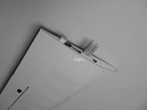
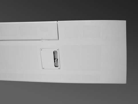
3 5. Place the aileron servo tray / hatch into the servo box on the bottom of the wing and drill 1,6mm pilot holes through the tray and the servo box for each of the four mounting screws. Secure the servo tray in place using the mounting screws provided ( 2mm x 12mm ). RIGHT WRONG 3. Repeat step # 1 - # 2 to install the control horn on the opposite aileron. To the cowl INSTALLING THE AILERON LINKAGES 1. Working with the aileron linkage for now, thread one nylon clevis at least 14 turns onto one of the 2mm x 180mm threaded wires Repeat step # 2 - # 5 to install the second aileron servo in the opposite wing half. To the cowl 7 2. Attach the clevis to the outer hole in the control horn. Install a silicone tube on the clevis Locate one nylon servo arm, and using wire cutters, remove all but one of the arms. Using a 2mm drill bit, enlarge the third hole out from the center of the arm to accommodate the aileron pushrod wire. INSTALLING THE CONTROL HORNS 1. One aileron control horn in positioned on each aileron. Using a ruler and a pen, locate and mark the location of the control horn. It should be mounted on the bottom side of the aileron at the leading edge, in line with the aileron pushrod Plug the aileron servo into the receiver and center the servo. Install the servo arm onto the servo. The servo arm should be perpendicular to the servo and point toward the middle of the wing. Drill two holes through the aileron using the control horn as a guide and screw the control horn in place. 5. Center the aileron and hold it in place using a couple of pieces of masking tape. 6. With the aileron and aileron servo centered, carefully place a mark on the aileron pushrod wire where it crosses the hole in the servo arm. 7. Using pliers, carefully make a 90 degree bend down at the mark made. Cut off the excess wire, leaving about 4mm beyond the bend. 8. Insert the 90 degree bend down through the hole in the servo arm. Install one nylon snap keeper over the wire to secure it to the arm. Install the servo arm retaining screw and remove the masking tape from the aileron. 6 2
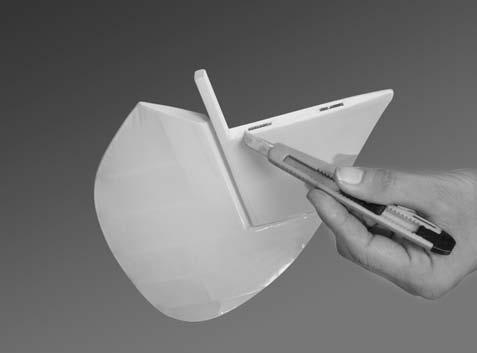
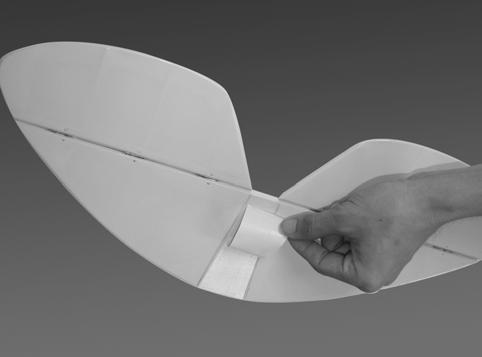
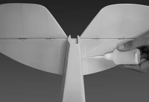
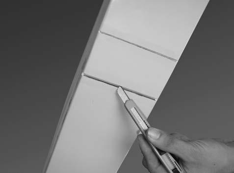
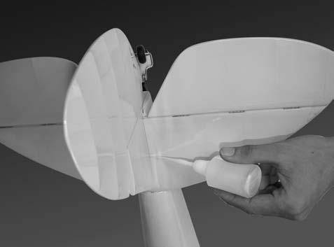
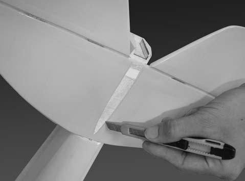
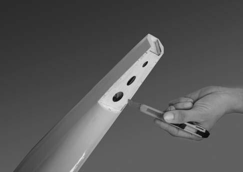
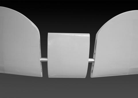
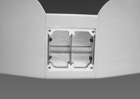
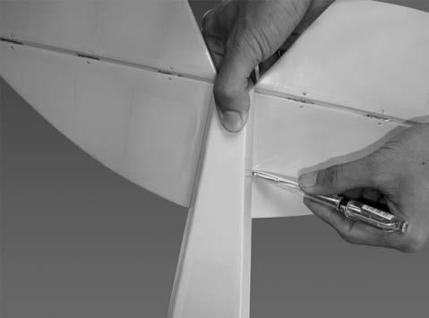
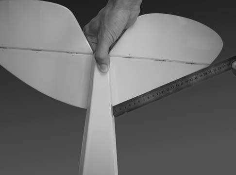
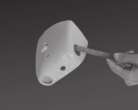
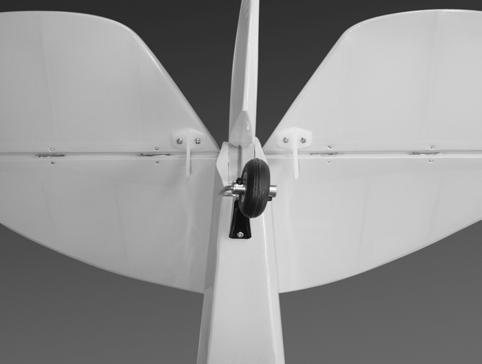
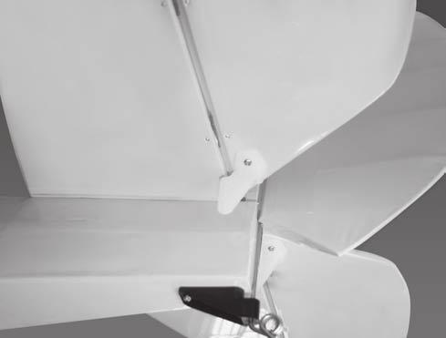
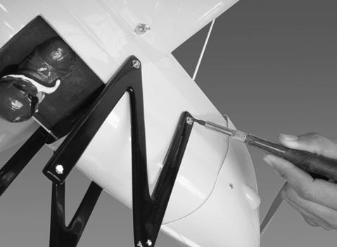
4 INSTALLING THE HORIZONTAL STABILIZER 1. Using a modeling knife, cut away the covering from the fuselage for the stabilizer and remove it. To the cowl Silicone Tube 8 9. Repeat step # 4 - # 8 to install the second aileron linkage. After both linkages are completed, connect both of the aileron servo leads using a Y-harness you have purchased separately. Remove the covering Draw a center line onto the horizontal stabilizer and slide it into the fuselage. 3. Check the fit of the horizontal stabilizer in its slot. Make sure the horizontal stabilizer is square and centered to the fuselage by taking measurements, but don't glue anything yet. To the cowl 9 JOINING THE upper WING HALVES - Slide the left and right wing to the center wing using the aluminum tube diheral With the horizontal stabilizer correctly aligned, mark the shape of the fuselage onto the bottom and into the top of the horizontal stabilizer using a water soluble/ non-permanent felt-tip pen Secure the wing using four nylon screws Remove the stabilizer. Using the lines you just drew as a guide, carefully remove the covering from between them using a modeling knife. When cutting through the covering to remove it, cut with only enough pressure to only cut through the covering it's self. Cutting into the balsa structure may weaken it. This could lead to possible failure during flight. 11 3
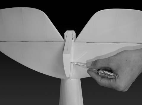
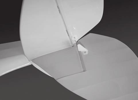
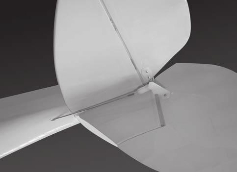
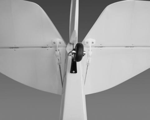
5 9. After the epoxy has fully cured, remove the masking tape or T-pins used to hold the stabilizer in place and carefully inspect the glue joints. Use more epoxy to fill in any gaps that were not filled previously and clean up the excess using a paper towel and rubbing alcohol. Remove the covering INSTALLING THE VERTICAL STABILIZER AND TAIL GEAR Remove the covering of the vertical. 6. Attach the lower wing to the fuselage as picture. 16 Remove the covering 7. Test the position of the elevator and adjust it as shown Mark the shape of the vertical onto the top of the horizontal. 8. When you are sure that everything is aligned correctly, mix up a generous amount of 30 minute epoxy. Apply a thin layer to the bottom of the stabilizer mounting area and to the stabilizer mounting platform sides in the fuselage. Insert the stabilizer in place and re-align. Double check all of your measurements one more time before the epoxy cures. Remove any excess epoxy using a paper towel and rubbing alcohol and hold the stabilizer in place with T-pins or masking tape Remove the covering Remove the covering
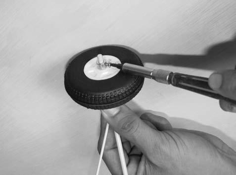
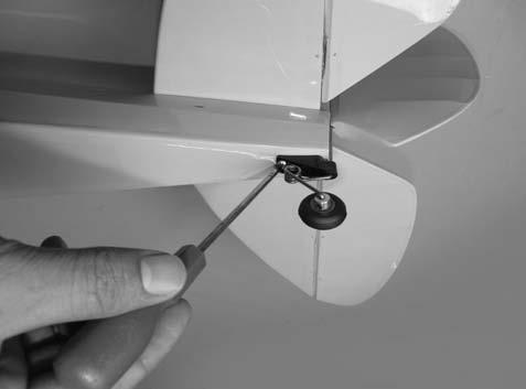
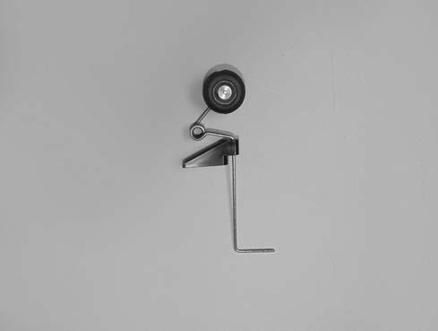
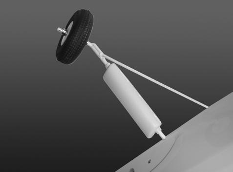
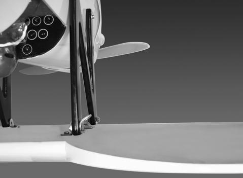
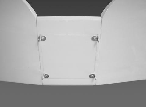
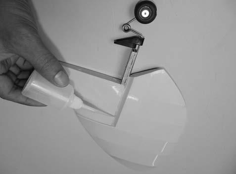
6 4. Prepare the tail gear as shown. 8. Secure the tail gear. 25mm 60mm Trim a channel and drill a hole onto the Rudder for tail gear as picture below. INSTALLING THE LANDING GEAR 1. Remove the covering. 20mm Make a slot Insert the Rudder to the vertical stabilizer and glue the hinge, and the tail gear in place. 2. Install the wheel and secure it. C.A glue Install the landing gear and secure it. 7. Glue the vertical stabilizer to the fuselage. Nylon strap
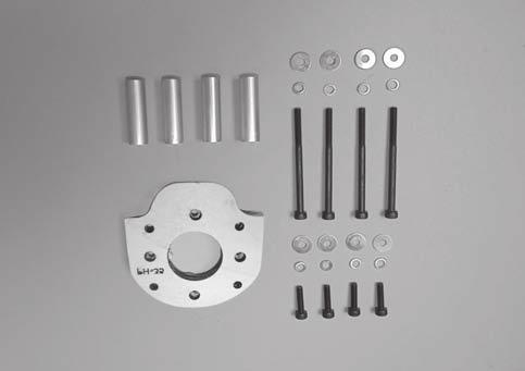
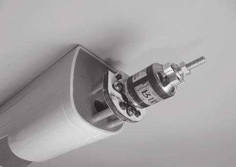
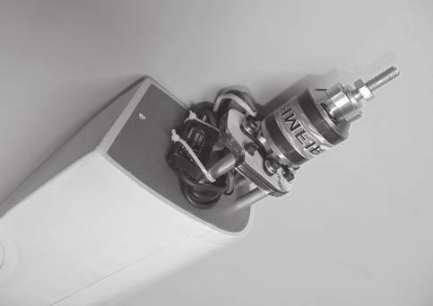
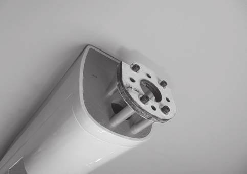
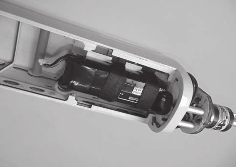
7 4. Attach and glue the plastic cover for the landing gear. 110mm Silicone glue 30 C.A glue 29 ENGINE INSTALLATION INSTALLING THE MOTOR AND BATTERY INSTALLING THE THROTTLE PUSHROD HOUSING Installing the electric motor 1. Install the engine mount into the fire wall using 4mm x 25mm screw. This model can fly with electric, here is our recommended for set up the system. 2. Place the engine into the engine mount and align it properly with the front of the cowling. The distance from the firewall to the front of the engine thrust washer should 110mm.! - Motor brushless: Rimfire Lipo cells: 6 cells / mah. - ESC: 50A - 70A. If your engine is equipped with a remote needle valve, we suggest installing it into the engine at this time. 16mm 3. When satisfied with the alignment of the engine, use a pencil and mark the mounting hole location onto the firewall, where the throttle pushrod will exit. 4. Now, remove the engine. Using a 5mm drill bit, drill holes through the firewall and the forward bulkhead at the marks made. 60mm 35mm 5. Slide the pushrod housing through the hole in the firewall, through the hole in the forward bulkhead, and into the servo compartment Apply a couple of drops of thin C/A to the pushrod housing where it exits the firewall and where it passes through the forward bulkhead. This will secure the housing in place. 7. Using a modeling knife, cut off the nylon pushrod housing 26mm in front of the servo tray. INSTALLING THE ENGINE 1. Locate the long piece of wire used for the throttle pushrod. One end of the wire has been pre-bend in to a "Z" bend at the factory. This "Z" bend should be inserted into the throttle arm of the engine when the engine is fitted onto the engine mount. Fit the engine to the engine mount using the screws provided. 32 6
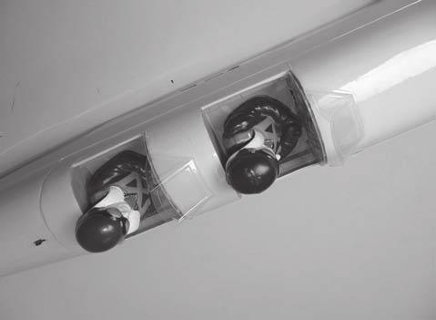
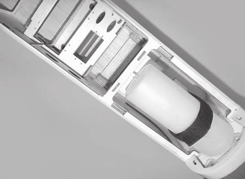
8 FUEL TANK INSTALLING THE STOPPER ASSEMBLY 1. The stopper has been pre-assembled at the factory. 2. Using a modeling knife, cut one length of silicon fuel line (the length of silicon fuel line is calculated by how the weighted clunk should rest about 8mm away from the rear of the tank and move freely inside the tank). Connect one end of the line to the weighted clunk and the other end to the nylon pick up tube in the stopper Carefully bend the second nylon tube up at a 45 degree angle (using a cigarette lighter). This tube will be the vent tube to the muffler. 4. Carefully bend the third nylon tube down at a 45 degree angle (using a cigarette lighter). This tube will be vent tube to the fueling valve! When the stopper assembly is installed in the tank, the top of the vent tube should rest just below the top surface of the tank. It should not touch the top of the tank ESC 5. Test fit the stopper assembly into the tank. It may be necessary to remove some of the flashing around the tank opening using a modeling knife. If flashing is present, make sure none of it falls into the tank When satisfied with the alignment of the stopper assembly tighten the 3mm x 20mm machine screw until the rubber stopper expands and seals the tank opening. Do not over tighten the assembly as this could cause the tank to split. Battery 7. Using a modeling knife, cut 3 lengths of fuel line 150mm long. Connect 2 lines to the 2 vent tubes and 1 line to the fuel pickup tube in the stopper. 8. Feed three lines through the fuel tank compartment and through the pre-drilled hole in the firewall. Pull the lines out from behind the engine, while guiding the fuel tank into place. Push the fuel tank as far forward as possible, the front of the tank should just about touch the back of the firewall. 36 7
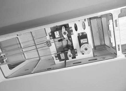
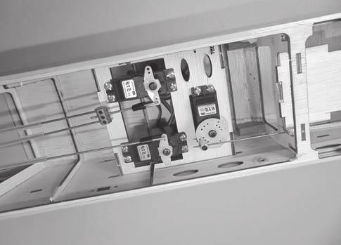
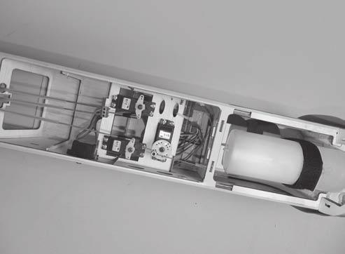
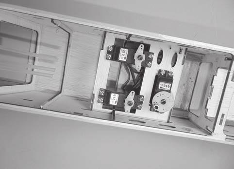
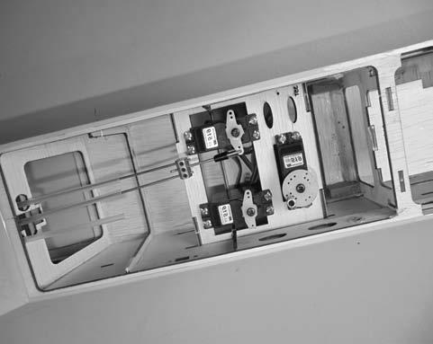
9 Blow through one of the lines to ensure the fuel lines have not become kinked inside the fuel tank compartment. Air should flow through easily.! Rudder servo Throttle servo Do not secure the tank into place permanently until after balancing the airplane. You may need to remove the tank to mount the battery in the fuel tank compartment. 9. To secure the fuel tank in place, apply a bead of silicon sealer to the forward area of the tank, where it exits the fuselage behind the engine mounting box and to the rear of the tank at the forward bulkhead. Elevator servo 39 INSTALLING THE ELEVATOR PUSHROD 10.Secure the fuel tank. 1. Locate the pushrod exit slot on the right side and left side of the fuselage. It is located slightly ahead and below the horizontal stabilizer. 2. Carefully cut away the covering material from the slot. Zip tie 3. Working from inside the fuselage, slide the threaded end of the pushrod until it reaches the exit slot. Carefully reach in with a small screw driver and guide the pushrod out of the exit slot. 4. Install the clevis on the elevator pushrod. Make sure 6mm of thread shows inside the clevis The control horn should be mounted on the bottom, left side and right side of the elevator at the leading edge, in line with the elevator pushrod. 6. Drill two holes through the elevator using the control horn as a guide and screw the control horn in place. To muffler To carburator To vent Tube 38 Control horn elevator SERVO INSTALLATION INSTALLING THE FUSELAGE SERVOS Install the rubber grommets and brass collets into the elevator, rudder and throttle servos. Test fit the servos into the servo tray. Trim the tray if necessary to fit your servos 2. Mount the servos to the tray using the mounting screws provided with your radio system. Control horn Control horn 41 8
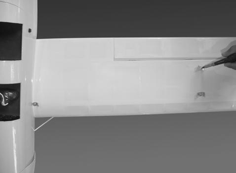
10 INSTALLING THE RUDDER PUSHROD 7. Attach clevis to the third hole in the control horn. Install a silicone tube on the clevis. 1. Locate the pushrod exit slot on the left of the fuselage. 2. Carefully cut away the covering material from the slot. Silicone tube 3. Working from inside the fuselage, slide the threaded end of the remaining pushrod down the inside of the fuselage until the pushrod reaches the exit slot. Carefully reach in with a small screw driver and guide the pushrod out of the exit slot. Silicone tube 4. Install the clevis on the rudder pushrod. Make sure 6mm of thread shows inside the clevis The control horn should be mounted on the left side of the rudder at the leading edge, in line with the rudder pushrod. 8. Locate one nylon servo arm, and using wire cutters, remove all but one of the arms. Using a 2mm drill bit, enlarge the third hole out from the center to accommodate the elevator pushrod wire. 6. Drill two holes through the rudder using the control horn as a guide and screw the control horn in place. 9. Plug the elevator servo into the receiver and center the servo. Install the servo arm onto the servo. The servo arm should be perpendicular to the servo and point toward the middle of the fuselage. Control horn 10. Be sure both elevator halves are flat. Center both elevator halves and hold them in place using a couple of pieces of masking tape. 11. Connect two elevator purshord to the metal domino connector and secure it. Insert the wire pushrod into the metal domino connector and secure it With the elevator halves and elevator servo centered, carefully place a mark on the elevator pushrod wire where it crosses the hole in the servo arm. 7. Attach clevis to the third hole in the control horn. Install a silicone tube on the clevis. 13. Using pliers, carefully make a 90 degree bend up at the mark made. Cut off the excess wire, leaving about 8mm beyond the bend. 14. Insert the 90 degree bend up through the hole in the servo arm, install one nylon snap keeper over the wire to secure it to the arm. Install the servo arm retaining screw and remove the masking tape the elevator halves. Silicone tube 15. Using thick CA glue, secure the pushrod sleeves to the pushrod sleeve guide Locate one nylon servo arm, and using wire cutters, remove all but one of the arms using a 2mm drill bit, enlarge the third hole out from the center to accommodate the rudder pushrod wire. Metal domino 9. Plug the rudder servo into the receiver and center the servo. Install the servo arm onto the servo. 10. Center the rudder and hold it in place using a piece of masking tape With the rudder and rudder servo centered, carefully place a mark on the rudder pushrod wire where it crosses the hole in the servo arm.
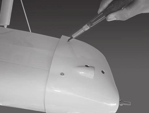
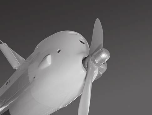
11 12. Using a pliers, carefully make a 90 degree bend up at the mark made. Cut off excess wire, leaving about 8mm beyond the bend. 13. Insert the 90 degree bend up through the hole in the servo arm. Install one nylon snap keeper over the wire to secure it to the arm. Install the servo arm retaining screw and remove the masking tape from the rudder. 14.Using thick CA glue, secure the pushrod sleeves to the pushrod sleeve guide. 47 MOUNTING THE COWL 1. Remove the muffler and needle valve assembly from the engine. Slide the fiberglass cowl over the engine. 2. Measure and mark the locations to be cut out for engine head clearance, needle valve, muffler. Remove the cowl and make these cutouts using a rotary tool with a cutting disc and a rotary sanding drum attachment Slide the cowl back into place. Align the front of the cowl with the crankshaft of the engine. The front of the cowl should be positioned so the crankshaft is in the middle of the precut opening. Hold the cowl firmly in place using several pieces of masking tape. INSTALLING THE THROTTLE 1. Install one adjustable metal connector through the third hole out from the center of one servo arm, enlarge the hole in the servo arm using a 2mm drill bit to accommodate the servo connector. Remove the excess material from the arm.! 4. While holding the cowl firmly in position, drill four 1,6mm pilot holes through both the cowl and the side edges of the firewall. 5. Using a 3mm drill bit, enlarge the four holes in the cowling. After installing the adjustable metal connector apply a small drop of thin C/A to the bottom nut. This will prevent the connector from loosening during flight.! 2. Plug the throttle servo into the receiver and turn on the radio system. Check to ensure that the throttle servo output shaft is moving in the correct direction. When the throttle stick is moved forward from idle to full throttle, the throttle barrel should also open and close using this motion. If not, reverse the direction of the servo, using the transmitter. 3. Slide the adjustable metal connector / servo arm assembly over the plain end of the pushrod wire. Position the throttle stick and the throttle trim at their lowest positions. 4. Manually push the carburator barrel fully closed. Angle the arm back about 45 degree from center and attach the servo arm onto the servo. With the carburator barrel fully closed, tighte the set screw in the adjustable metal connector. Enlarging the holes through the cowl will prevent the fiberglass from splitting when the mounting screws are installed. 6. Slide the cowl back over the engine and secure it in place using four 3mm x 12mm wood screws. 7. Install the muffler. Connect the fuel and pressure lines to the carburator, muffler and fuel filler valve. Tighten the screws completely Remove the excess throttle pushrod wire using wire cutters and install the servo arm retaining screw. 10
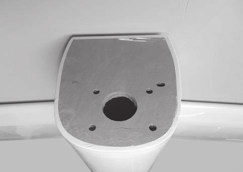
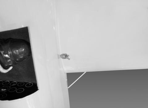
12 2. Cut out the switch hole using a modeling knife. Use a 2mm drill bit and drill out the two mounting holes through the fuselage side. 3. Secure the switch in place using the two machine screws provided with the radio system. Switch 49 Battery Receiver 51 INSTALLING THE WING Cowl area cutout for proper airflow to carburetor. 1. Two holes are ready mark on the Top side of the wing. 50 INSTALLING THE RECEIVER AND BATTERY Remove the covering 1. Plug the servo leads and the switch lead into the receiver. You may want to plug an aileron extension into the receiver to make plugging in the aileron servo lead easier when you are installing the wing. Plug the battery pack lead into the switch Wrap the receiver and battery pack in the protective foam to protect them from vibration. Use a rubber band or masking tape to hold the foam in place. 2. Install two aluminum plate to the lower wing. INSTALLING THE SWITCH 1. The switch should be mounted on the fuselage side, opposite the muffler, close enough to the receiver so the lead will reach. Use the face plate of the switch cut out and locate the mounting holes
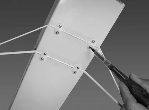
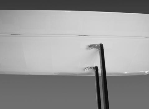
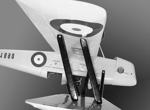
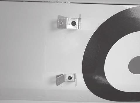
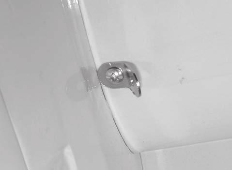
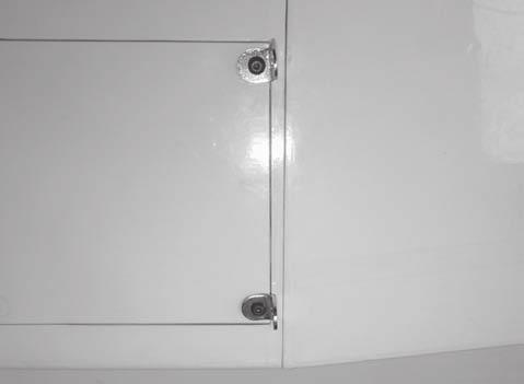
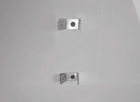
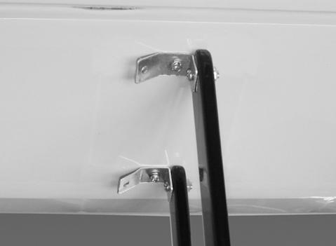
13 Install the metal strap to the lower wing as picture below. 5. Install two metal strap to the upper wing as picture below. Aluminum plate Aluminum plate Install the wing strut as picture below. 4. Install four metal strap into the upper wing as picture below
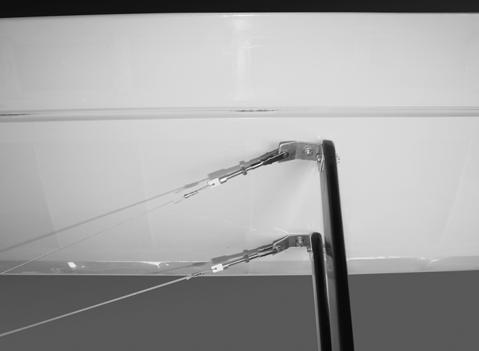
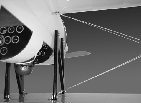
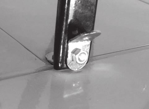
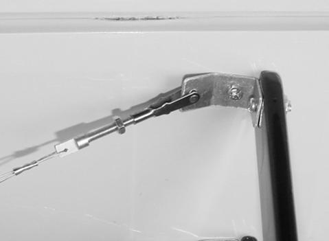
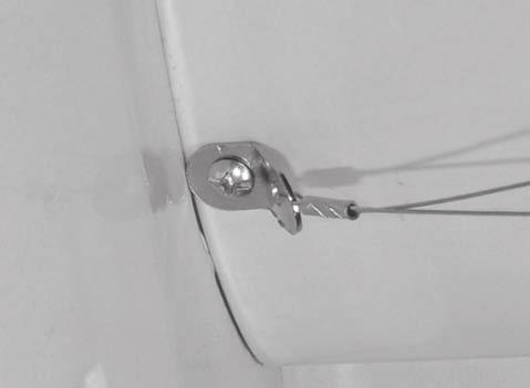
14 LOCATION OF WING STRUT Front Wing strut Aluminum plate Install the upper wing to the wing strut. Metal strap Install the cable. Short Metal strap Front Long Install two wing strut to the both wing. Long Short
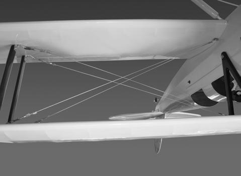
15 BALANCING 10. Install the cable. 1. It is critical that your airplane be balanced correctly. Improper balance will cause your plane to lose control and crash. THE CENTER OF GRAVITY IS LOCATED 90mm BACK FROM THE LEADING EDGE OF THE UPPER WING, AT THE FUSELAGE. 2. Mount the wing to the fuselage. Using a couple of pieces of masking tape, place them on the top side of the wing 90mm back from the leading edge, at the fuselage sides Lift the airplane. Place your fingers on the masking tape and carefully lift the plane. 4. If the nose of the plane falls, the plane is heavy nose. To correct this first move the battery pack further back in the fuselage. If this is not possible or does not correct it, stick small amounts of lead weight on the fuselage under the horizontal stabilizer. If the tail of the plane falls, the plane is tail heavy. To correct this, move the battery and receiver forward or if this is not possible, stick weight into the firewall. When balanced correctly, the airplane should sit level or slightly nose down when you lift it up with your fingers mm 11. Install the cable. 90mm LATERAL BALANCE 71 After you have balanced a plane on the C.G.! You should laterally balance it. Doing this will help the airplane track straighter. INSTALLING THE CANOPY and PILOT 1. Turn the airplane upside down. Attach one loop of heavy string to the engine crankshaft and one to the tail wheel wire. With the wings level, carefully lift the airplane by the string. This may require two people to make it easier. Canopy 2. If one side of the wing fall, that side is heavier than the opposite. Add small amounts of lead weight to the bottom side of the lighter wing half's wing tip. Follow this procedure until the wing stays level when you lift the airplane. Glue with epoxy Pilot 72 14
16 CONTROL THROWS 1. We highly recommend setting up a plane using the control throws listed. 2. The control throws should be measured at the widest point of each control surface. 3. Check to be sure the control surfaces move in the correct directions. Ailerons : 10mm up Elevator : 8mm up Rudder : 25mm right 10mm down 8mm down 25mm left FLIGHT PREPARATION PRE FLIGHT CHECK 1. Completely charge your transmitter and receiver batteries before your first day of flying. 10mm 10mm 2. Check every bolt and every glue joint in your plane to ensure that everything is tight and well bonded. Aileron Control 3. Double check the balance of the airplane. 8mm 8mm 4. Check the control surface. 5. Check the receiver antenna. It should be fully extended and not coiled up inside the fuselage. Elevator Control 6. Properly balance the propeller. 25mm 25mm Rudder Control 15
RECOMMENDED MOTOR AND BATTERY SET UP
 SPECIFICATION - Wingspan: 1410mm (55.5 in) - Length: 1278mm (50.3 in) - Flying weight: 3.2-3.4 kg - Wing area: 41.3 dm2 - Wing loading: 75g/dm2 - Wing type: Naca airfoils - Covering type: Genuine ORACOVER
SIZE.120 OR 30CC SCALE 1:5 ARF
 PC21 PILATUS MK2 SIZE.120 OR 30CC SCALE 1:5 ARF SPECIFICATION - Wingspan: 1772mm (69.72in) - Length: 2019mm (79.5 in) - Flying weight: 6.4-7.2 kg - Wing area: 57.6 dm2 - Wing loading: 113g/dm2 - Wing type:
RECOMMENDED MOTOR AND BATTERY SET UP
 SPECIFICATION - Wingspan: 1800mm (70.8 in) - Length: 1355mm (53.3 in) - Flying weight: 4100-4300 g - Wing area: 51 dm2 - Wing loading: 80g/dm2 - Wing type: Naca airfoils - Covering type: Genuine ORACOVER
RECOMMENDED MOTOR AND BATTERY SET UP
 SPECIFICATION - Wingspan: 2000mm (78.7in) - Length: 1544mm (60.7 in) - Flying weight: 3600-3800 gr - Wing area: 66 dm2 - Wing loading: 55g/dm2 - Wing type: Naca airfoils - Covering type: Genuine ORACOVER
I n s t r u c t i o n M a n u a l. Instruction Manual SPECIFICATION
 I n s t r u c t i o n M a n u a l Instruction Manual SPECIFICATION - Wingspan: 3200mm (125,9 in) - Length: 1650mm (64,9 in) - Flying weight: 3000gr 3200gr - Wing area: 64.5 dm2 - Wing loading: 46g/dm2
RECOMMENDED MOTOR AND BATTERY SET UP
 SPECIFICATION - Wingspan: 1420mm (55.91 in) - Length: 1370mm (53.94 in) - Flying weight: 2600-2800 gr - Wing area: 41.6 dm2 - Wing loading: 65g/dm2 - Wing type: Naca airfoils - Covering type: Genuine ORACOVER
RECOMMENDED MOTOR AND BATTERY SET UP
 SPECIFICATION - Wingspan: 2190mm (86.2 in) - Length: 1907mm (75 in) - Flying weight: 9000-12000 gr - Wing area: 92 dm2 - Wing loading: 98g/dm2 - Wing type: Naca airfoils - Retract gear type: Air-retract
I/C FLIGHT GUIDELINES
 SPECIFICATION - Wingspan: 3500mm (137.8 in) - Length: 1650mm (64.96 in) - Flying weight: 3700-4000 gr - Wing area: 75 dm2 - Wing loading: 49g/dm2 - Wing type: HQ profile - Covering type: Genuine ORACOVER
1660mm (65.4 in) 1200mm (47.2 in) 2700gr gr 6 channel - 7 servo standard 46/ 2 stroke or 52/ 4 stroke
 1200mm (47.2 in) 2700gr gr 6 channel - 7 servo standard 46/ 2 stroke or 52/ 4 stroke") Instruction Manual CESSNA-46 1660mm (65.4 in) 1200mm (47.2 in) 2700gr - 3000gr 6 channel - 7 servo standard 46/ 2 stroke or 52/ 4 stroke KIT CONTENTS: We have organized the parts as they come out of the
Instruction Manual CESSNA-46 1660mm (65.4 in) 1200mm (47.2 in) 2700gr - 3000gr 6 channel - 7 servo standard 46/ 2 stroke or 52/ 4 stroke KIT CONTENTS: We have organized the parts as they come out of the
RECOMMENDED MOTOR AND BATTERY SET UP
 SPECIFICATION - Wingspan: 6000mm (236.2 in) - Length: 2873mm (113.1 in) - Flying weight: 14-18 kg - Wing area: 219.4 dm2 - Wing loading: 64g/dm2 - Wing type: HQ airfoils - Covering type: Genuine ORACOVER
to fly. Most hardware included and all replacement parts are available.
 Instruction Manual The Thunderbolt P47 was perhaps the greatest of world war II in terms of all round performance and capability Phoenix Model has recreated a 2C - 60 class engine (or 4c 91 class) It was
Instruction Manual. Wingspan : 1400mm (55.12 in) : 1370mm (53.94 in) : 2600gr gr. : 4 channel / 5 servo. : / 2 stroke_52-71 / 4 stroke
 : 1370mm (53.94 in) : 2600gr gr. : 4 channel / 5 servo. : / 2 stroke_52-71 / 4 stroke") Instruction Manual 540 Wingspan : 1400mm (55.12 in) g Length : 1370mm (53.94 in) Weight : 2600gr - 2800gr Radio : 4 channel / 5 servo Engine : 46-52 / 2 stroke_52-71 / 4 stroke KIT CONTENTS: We have organized
Instruction Manual 540 Wingspan : 1400mm (55.12 in) g Length : 1370mm (53.94 in) Weight : 2600gr - 2800gr Radio : 4 channel / 5 servo Engine : 46-52 / 2 stroke_52-71 / 4 stroke KIT CONTENTS: We have organized
RECOMMENDED MOTOR AND BATTERY SET UP
 SPECIFICATION - Wingspan: 1669mm (65.7in) - Length: 1229mm (48.43 in) - Flying weight: 3300-3400 gr - Wing area: 44.2 dm2 - Wing loading: 67g/dm2 - Wing type: Naca airfoils - Covering type: Genuine ORACOVER
Instruction Manual. Wingspan : 2270mm (89.37 inches) : 1870mm (73.62 inches) : 7400gr gr. : 4 channel - 6 standard servo.
 : 1870mm (73.62 inches) : 7400gr gr. : 4 channel - 6 standard servo.") Wingspan : 2270mm (89.37 inches) g Length : 1870mm (73.62 inches) Weight : 7400gr - 7600gr Radio : 4 channel - 6 standard servo Engine : 25cc-35cc KIT CONTENTS: We have organized the parts as they come
Wingspan : 2270mm (89.37 inches) g Length : 1870mm (73.62 inches) Weight : 7400gr - 7600gr Radio : 4 channel - 6 standard servo Engine : 25cc-35cc KIT CONTENTS: We have organized the parts as they come
HERO 3D SCALE 1:6 ARF
 Instruction Manual SPECIFICATION - Wingspan: 1500mm(59 in) - Length: 1410mm (55.5 in) - Flying weight: 2100-2300 gr - Wing area: 58 dm2 - Wing loading: 39g/dm2 - Covering type: Genuine ORACOVER - Gear
SBACH SCALE 1:4 ½ ARF
 SPECIFICATION - Wingspan: 1663mm (65.5 in) - Length: 1638mm (64.5 in) - Flying weight: 4700-5200 gr - Wing area: 56 dm2 - Wing loading: 85g/dm2 - Wing type: Naca airfoils - Covering type: Genuine ORACOVER
RECOMMENDED MOTOR AND BATTERY SET UP
 Instruction Manual SPECIFICATION - Wingspan: 1418mm (55.8 in) - Length: 1314mm (51.7 in) - Flying weight: 2700-3200 gr - Wing area: 36.8 dm2 - Wing loading: 76g/dm2 - Wing type: Naca airfoils - Covering
RECOMMENDED MOTOR AND BATTERY SET UP
 SPECIFICATION - Wingspan: 2567mm (101in) - Length: 2190mm (86.2 in) - Flying weight: 11-13 kg - Wing area: 101 dm2 - Wing loading: 99g/dm2 - Wing type: Naca airfoils - Covering type: Genuine ORACOVER -
: 6 channel - 9 servo
 g Wingspan : 2005mm (78.94 inches) Length : 1640mm (64.57 inches) Weight : 6400g - 6600g Engine : 25cc - 35cc Radio : 6 channel - 9 servo KIT CONTENTS: We have organized the parts as they come out of
Instruction Manual. Wingspan : 1694mm (66.69 in) : 1470mm (57.87 in) : 3200gr gr. : 61 two stroke/ 71 four stroke. : 6 channel / 7 servo
 : 1470mm (57.87 in) : 3200gr gr. : 61 two stroke/ 71 four stroke. : 6 channel / 7 servo") Wingspan : 1694mm (66.69 in) g Length : 1470mm (57.87 in) Weight : 3200gr - 3800gr Engine : 61 two stroke/ 71 four stroke Radio : 6 channel / 7 servo KIT CONTENTS: We have organized the parts as they
Wingspan : 1694mm (66.69 in) g Length : 1470mm (57.87 in) Weight : 3200gr - 3800gr Engine : 61 two stroke/ 71 four stroke Radio : 6 channel / 7 servo KIT CONTENTS: We have organized the parts as they
Instruction Manual. Wingspan : 1884 mm (74.17 in) Length. Weight. Engine. : 4 channels / 5 servo standard. : 1450 mm (57.
 Length. Weight. Engine. : 4 channels / 5 servo standard. : 1450 mm (57.") Wingspan : 1884 mm (74.17 in) Length : 1450 mm (57.09 in) Weight : 4000 gr Engine : 60 two strokes Radio : 4 channels / 5 servo standard KIT CONTENTS: We have organized the parts as they come out of the
Wingspan : 1884 mm (74.17 in) Length : 1450 mm (57.09 in) Weight : 4000 gr Engine : 60 two strokes Radio : 4 channels / 5 servo standard KIT CONTENTS: We have organized the parts as they come out of the
YAK54 MK2. GP/EP size.120/20cc SCALE 1:4 ¾ ARF. Instruction Manual. version. version
 Instruction Manual GP EP version version GP/EP size.10/0cc SCALE 1:4 ¾ ARF SPECIFICATION - Wingspan: 168 (66.3 in) - Length: 1605mm (63.1 in) - Flying weight: 4700-500 gr - Wing area: 54.7 dm - Wing loading:
SBD DAUNTLESS GP/EP SIZE ARF SCALE 1:8. Instruction Manual
 GP/EP SIZE.46-.55 ARF SCALE 1:8 SPECIFICATION - Wingspan: 1440mm (56.7in) - Length: 1140mm (44.9 in) - Flying weight: 3000-3300 g - Wing area: 42 dm2 - Wing loading: 78g/dm2 - Wing type: Naca airfoils
Instruction Manual. Wingspan : 1400 mm (55.12 inch) : 1480 mm (58.27 inch) : 5500gr gr. : 6-9 channel/ 8 servo high torque,1 standard
 : 1480 mm (58.27 inch) : 5500gr gr. : 6-9 channel/ 8 servo high torque,1 standard") Wingspan : 1400 mm (55.12 inch) g Length : 1480 mm (58.27 inch) Weight : 5500gr - 6000gr Radio : 6-9 channel/ 8 servo high torque,1 standard Engine : GT 22 OS KIT CONTENTS: We have organized the parts
Wingspan : 1400 mm (55.12 inch) g Length : 1480 mm (58.27 inch) Weight : 5500gr - 6000gr Radio : 6-9 channel/ 8 servo high torque,1 standard Engine : GT 22 OS KIT CONTENTS: We have organized the parts
: 7 channel - 9 servo, Hi-Torque ( Minimum 6 kg ).
.") g Wingspan : 1820mm (71.65 inches) Length : 1625mm (63.98 inches) Weight : 6900gr Engine : 25cc - 35cc Radio : 7 channel - 9 servo, Hi-Torque ( Minimum 6 kg ). KIT CONTENTS: We have organized the parts
g Wingspan : 1820mm (71.65 inches) Length : 1625mm (63.98 inches) Weight : 6900gr Engine : 25cc - 35cc Radio : 7 channel - 9 servo, Hi-Torque ( Minimum 6 kg ). KIT CONTENTS: We have organized the parts
Instruction Manual book
 book SPECIFICATION Wingspan : 1,450 mm 57.09 in. Length : 1,200mm 47.24in. Weight : 3.1 kg 6.82 Lbs. Radio : 05 channels. Servo : 07 servos. Engine : 61-75 2 stroke. 91 4 stroke. Made in Vietnam. This
the leading edge of the wing, at the fuselage - Length: 1540mm (60.6 in) 10% expo; High: 15mm up/down, 10% expo - Wing area: 40dm2
 10% expo; High: 15mm up/down, 10% expo - Wing area: 40dm2") SPECIFICATION - Gravity CG: 165-170 mm (6.5-6.7 in) Back from - Wingspan: 1400mm (55.1 in) the leading edge of the wing, at the fuselage - Length: 1540mm (60.6 in) - Control throw Ailerons: Low: 12mm up/down,
SPECIFICATION - Gravity CG: 165-170 mm (6.5-6.7 in) Back from - Wingspan: 1400mm (55.1 in) the leading edge of the wing, at the fuselage - Length: 1540mm (60.6 in) - Control throw Ailerons: Low: 12mm up/down,
INSTRUCTION MANUAL BOOK
 INSTRUCTION MANUAL BOOK ITEM CODE BH57. SPECIFICATION Wingspan: 1,470 mm. 57.87 in. Length : 1,180 mm. 46.46 in. Weight : 2.7 Kg. 5.94 Lbs. Engine : 46 cu.in 2 stroke. 52 cu.in 4 stroke. Radio : 4 channels.
Instruction Manual book
 Instruction Manual book SPECIFICATION Wingspan : 1,800mm. 70.87 in. Length : 1,350 mm. 53.15in. Weight : 3.6kg. 7.92lbs. Parts Listing required (not included). Glow Engine : 55-61 2 stroke. 91 4 stroke.
Instruction Manual book
 book SPECIFICATION Wingspan : 1,920 mm 75.59 in. Length : 1,560 mm 61.42 in. Weight : 5 kg 11.00Lbs. Radio : 06 channels. Servo : 09 servos. Engine : 120 4 stroke. Made in Vietnam. This instruction manual
RECOMMENDED MOTOR AND BATTERY SET UP
 SPECIFICATION - Wingspan: 1600mm (63 in) - Length: 1285mm (50.5 in) - Flying weight: 2800-3200 gr - Wing area: 40.1 dm2 - Wing loading: 78g/dm2 - Wing type: Naca airfoils - Covering type: Genuine ORACOVER
Instruction Manual. Specification:
 Instruction Manual L O W Specification: Wingspan: 133 cm (52.3 inches) Length : 104 cm (40.9 inches) Weight : 1790gr Engine : 25-32 two stroke Radio : 4 channel - 4 servo W I N G KIT CONTENTS: We have
Instruction Manual. Wingspan : 1670mm. : 3400gr gr. : 61/75 two stroke. : 5 servo + 1 servo retract / 6 channel
 Wingspan : 1670mm g Length Weight Engine Radio : 1350mm : 3400gr - 4000gr : 61/75 two stroke : 5 servo + 1 servo retract / 6 channel KIT CONTENTS: We have organized the parts as they come out of the box
Instruction Manual book
 Instruction Manual book SPECIFICATION Wingspan : 1,920 mm 75.59 in. Length : 1,560 mm 61.42 in. Weight : 5 kg 11.00Lbs. Radio : 06 channels. Servo : 09 servos. Engine : 120 4 stroke. Made in Vietnam. JU87-STUKA
RECOMMENDED EDF AND BATTERY SET UP
 SPECIFICATION - Wingspan: 1150mm (45.3 in) - Length: 1587mm (62.5 in) - Flying weight: 5.0-5.3 kg - Wing area: 40dm2 - Wing loading: 125g/dm2 - Wing type: Naca airfoils - Covering type: Genuine ORACOVER
Instruction Manual book
 Instruction Manual book SPECIFICATION Wingspan : 1,920 mm 75.59 in. Length : 1,560 mm 61.42 in. Weight : 5 kg 11.00Lbs. Radio : 06 channels. Servo : 09 servos. Engine : 120 4 stroke. Made in Vietnam. JU87-STUKA
HIGH WING MK2 GP/EP ARF SCALE
 SONIC HIGH WING MK2 GP/EP.25-.32 ARF SCALE 1:10 SPECIFICATION - Wingspan: 1340mm (52.7in) - Length: 1040mm (40.9 in) - Flying weight: 1800-2000 gr - Wing area: 27 dm2 - Wing loading: 79g/dm2 - Wing type:
TUCANO 60CC SCALE 1:4 ¼ ARF. Instruction Manual. version. version
 Instruction Manual GP EP version version SCALE 1: ¼ ARF SPECIFICATION - Wingspan: 567mm (101in) - Length: 190mm (86. in) - Flying weight: 11-13 kg - Wing area: 101 dm - Wing loading: 99g/dm - Wing type:
Instruction Manual book
 Instruction Manual book ITEM CODE: BH39. SPECIFICATION Wingspan : 181 cm 71.26 inches. Length : 155 cm 61.024 inches. Weight : 04 kg 8.8 lbs. Servo : 9 servos. Radio : 6 channels. Engine : 91 cu.in - 2
Instruction Manual book
 Instruction Manual book ITEM CODE: BH56. SPECIFICATION Wingspan : 1,660 mm 65.35 in. Length : 1,420 mm 55.91 in. Weight : 3.8 kg 8.36 Lbs. Radio : 06 channels. Servo : 08 servos. Engine : 75 Cu.in 2 Stroke.
Instruction Manual book
 book SPECIFICATION Wingspan : 2,080 mm 81.89 in. Length : 1,680 mm 66.14 in. Weight : 6.2 kg 13.64 Lbs. Radio : 06 channels. Servo : 06 servos. Engine : 30-35 CC Gas(FUJI IMVAC). Made in Vietnam. This
Instruction Manual book
 book SPECIFICATION Wingspan : 2,310 mm 90.94 in. Length : 1,750 mm 68.90 in. Weight : 8.4 kg 18.48 Lbs. Radio : 06 channels. Servo : 09 servos + 2 mini servos (elevator). Engine : 45-55CC gas. Made in
Instruction Manual book
 Instruction Manual book SPECIFICATION Wingspan : 2,170 mm 85.43 in. Length : 1,760 mm 69.29 in. Weight : 6.3 kg 13.86 Lbs. Radio : 06 channels. Servo : 08 servos. Engine : 45-50CC Gas. Made in Vietnam.
Instruction Manual book
 Instruction Manual book SPECIFICATION Wingspan : 1,780 mm 70.08 in. Length : 1,520 mm 59.84 in. Weight : 4.8 kg 10.56 Lbs. Radio : 06 channels. Servo : 09 servos. Engine : 120 4stroke Made in Vietnam.
Instruction Manual book
 book ITEM CODE: BH99. SPECIFICATION Wingspan : 2,850 mm 112.20 in. Length : 1,910 mm 75.20 in. Weight : 8.1 kg 17.82 Lbs. Radio : 06 channels. Servo : 08 servos. Engine : 35 CC gas. Made in Vietnam. This
Instruction Manual book
 book ITEM CODE:BH 115. SPECIFICATION Wingspan : 6,000 mm 236,22 in. Length : 2,740 mm 107,87 in. Weight : 17.5kg 38.5Lbs. Radio : 08 channels. Servo : 07-08 HS-5685MH(HITEC) Battery : 2 Cells-Li-Po 7.4V
Instruction Manual Book
 Book ITEM CODE: BH99. SPECIFICATION Wingspan : 2,850 mm 112.20 in. Length : 1,910 mm 75.20 in. Weight : 8.1 kg 17.82 lbs. Parts listing required (not included): Radio : 06 channels. Servo : 08 standard
Instruction Manual book
 Instruction Manual book Item code:bh117 SPECIFICATION Wingspan : 2,100 mm 82.68 in. Length : 1,875 mm 73.82 in. Weight : 7.5 kg 16.5 Lbs. Parts listing required (not included) Radio : 08 channels. Servo
Instruction Manual book
 Instruction Manual book Item code:bh117 SPECIFICATION Wingspan : 2,100 mm 82.68 in. Length : 1,875 mm 73.82 in. Weight : 7.5 kg 16.5 Lbs. Radio : 08 channels. Servo : 09 servos. Engine : 33-45cc gas. Made
Instruction Manual BULLDOG. Wingspan : 1410 mm (55.5in) : 1450 mm (57.1in) : 4900gr gr. Weight. : 6-9 Channel/ 7 servo high torque, 1standard
 : 1450 mm (57.1in) : 4900gr gr. Weight. : 6-9 Channel/ 7 servo high torque, 1standard") Wingspan : 1410 mm (55.5in) Length Weight Radio Engine : 1450 mm (57.1in) : 4900gr - 5600gr : 6-9 Channel/ 7 servo high torque, 1standard : 1.20/ 2 stroke 1.80/ 4 stroke KIT CONTENTS: We have organized
Wingspan : 1410 mm (55.5in) Length Weight Radio Engine : 1450 mm (57.1in) : 4900gr - 5600gr : 6-9 Channel/ 7 servo high torque, 1standard : 1.20/ 2 stroke 1.80/ 4 stroke KIT CONTENTS: We have organized
Instruction Manual book
 book ITEM CODE: BH109 SPECIFICATION Wingspan : 2,200mm. 86.61 in. Length : 1,976 mm. 77.80in. Weight : 8.3 kg. 18.26 lbs. Part listing required (not included) Glow Engine : 55 CC Gas Servo : 9 servos.
Instruction Manual book
 book ITEM CODE:BH 124 SPECIFICATION Wingspan : 2,240 mm 88.19 in. Length : 1,625 mm 63.98 in. Weight : 6,4 kg 14.08Lbs. Radio : 08 channels. Servo : 09 servos. Engine : 26-35cc Gas. Made in Vietnam. This
Instruction Manual book
 Instruction Manual book ITEM CODE: BH122. SPECIFICATION Wingspan : 2,200 mm 86.61 in. Length : 1,640 mm 64.57 in. Weight : 6.5 kg 14.3Lbs. Parts listing required (not included). Radio : 8 channels. Servo
Instruction Manual book
 book SPECIFICATION Wingspan : 1.750mm 68.90 in. Length : 1.280 mm 50.39 in. Weight : 3.2-3.5 kg 7.04-7.7 Lbs. Radio : 06 channels. Servo : 07-09 mini servos +3 servos retracts (FUTABA,S3170G) Parts listing
Instruction Manual book
 book ITEM CODE:BH 72 SPECIFICATION Wingspan : 2,350 mm 92.52 in. Length : 1,730 mm 68.11 in. Weight : 6.4 kg 14.08 Lbs. Radio : 06 channels. Servo : 08 servos. Engine : OS. GT22-26cc gas. Made in Vietnam.
Instruction Manual book
 Instruction Manual book SPECIFICATION Wingspan : 2,060 mm 81.10 in. Length : 1,460 mm 57.48 in. Weight : 4.8 kg 10.56 Lbs. Radio : 06 channels. Servo : 07 servos. Engine : 46 2 stroke (2pcs). Made in Vietnam.
Instruction Manual book
 book Item code:bh77 SPECIFICATION Wingspan : 1,740 mm 68.50 in. Length : 1,440 mm 56.69 in. Weight : 4.4 kg 9.68 Lbs. Radio : 06 channels. Servo : 09 servos + 2 mini servos(wheel door). Engine : 120-4
Instruction Manual book
 Instruction Manual book ITEM CODE: BH120. SPECIFICATION Wingspan : 1,600 mm 62.99 in. Length : 1,184 mm 46.61 in. Weight : 3.1 kg 6.82Lbs. Radio : 5 channels. Servo : 04-05 servos Engine : 46-2 stroke
INSTRUCTION MANUAL BOOK
 INSTRUCTION MANUAL BOOK ITEM CODE: BH 36. SPECIFICATION Wingspan : 1,620 mm 64 in. Length : 1,340 mm 53 in. Weight : 3.8 Kg 8.36 Lbs. Engine : 15 CC Gas Radio : 8 Channels Servo : 8Servos + 2 servos Retract
Instruction Manual book
 book ITEM CODE:BH101. SPECIFICATION Wingspan : 1,940 mm 76.38 inches. Length : 1,700 mm 66.93 inches. Weight : 5.8 kg 12.76 lbs. Radio : 6 channels. Servo : 8 servos. Glow Engine : 26-30cc gas. Made in
Instruction Manual EXTRA 260-EP. 1075mm (42.32 in) 1000mm (39.37 in) 1100gr gr. 4 channel - 4 mini servo. Axi motor 2820
 1000mm (39.37 in) 1100gr gr. 4 channel - 4 mini servo. Axi motor 2820") 1075mm (42.32 in) 1000mm (39.37 in) 1100gr - 1400gr 4 channel - 4 mini servo Axi motor 2820 KIT CONTENTS: We have organized the parts as they come out of the box for better identification during assembly.
1075mm (42.32 in) 1000mm (39.37 in) 1100gr - 1400gr 4 channel - 4 mini servo Axi motor 2820 KIT CONTENTS: We have organized the parts as they come out of the box for better identification during assembly.
Instruction Manual book
 Instruction Manual book ITEM CODE:BH 140 SPECIFICATION Wingspan : 2,050mm 80.71 in. Length : 1,840 mm 72.41 in. Weight : 6.8kg 14.96 Lbs. Radio : 07 channels. Servo : 09 servos. Engine: O.S GT 33 CC gas.
Instruction Manual book
 Instruction Manual book ITEM CODE:BH118. SPECIFICATION Wingspan : 1,050 mm 41.34 inches. Length : 950mm 37.4 inches. Weight : 1 kg 2.2 lbs. Radio : 04 channels. Servo : 4 mini servos. Motor : KMS 2814/05
TURBO BEAVER. Instruction Manual Book. Item code: BH % ALMOST READY TO FLY ALL BALSA - PLY WOOD CONSTRUCTION. COVERED WITH ORACOVER
 Instruction Manual Book. TURBO BEAVER ALL BALSA - PLY WOOD CONSTRUCTION. COVERED WITH ORACOVER 95% ALMOST READY TO FLY SPECIFICATION: - Wingspan: 2,250 mm (88.58 in). Length: 1,675 mm ( 65.94 in). Weight:
Instruction Manual book
 book ITEM CODE:BH 136 SPECIFICATION Wingspan : 2,000mm 78.74 in. Length : 1,760 mm 69.29 in. Weight : 6.8kg 14.96 Lbs. Parts listing required (not included). Engine : 0.S GT 33cc gas Radio : 07 channels.
Instruction Manual book
 Instruction Manual book ITEM CODE:BH118. SPECIFICATION Wingspan : 1,050 mm 41.34 inches. Length : 950mm 37.4 inches. Weight : 1 kg 2.2 lbs. Radio : 04 channels. Servo : 4 mini servos. Motor : BL2215/20
Instruction Manual MUSTANG P51 - EP. Wingspan : 1377mm (54.21in) : 1180mm (46.46 in) : 2200gr gr. : AXI motor 2826 or 4120
 : 1180mm (46.46 in) : 2200gr gr. : AXI motor 2826 or 4120") Instruction Manual MUSTANG P51 - EP Wingspan : 1377mm (54.21in) g Length : 1180mm (46.46 in) Weight : 2200gr - 2600gr Engine : AXI motor 2826 or 4120 Radio : 4 channel / 4 servos standard KIT CONTENTS:
Instruction Manual MUSTANG P51 - EP Wingspan : 1377mm (54.21in) g Length : 1180mm (46.46 in) Weight : 2200gr - 2600gr Engine : AXI motor 2826 or 4120 Radio : 4 channel / 4 servos standard KIT CONTENTS:
ASSEMBLY MANUAL. Kit features. MS:110
 MS:110 ASSEMBLY MANUAL Graphics and specifications may change without notice. Specifications: Wing span-------------------------------------------------- 62.9 in---------------------------------------
ASSEMBLY MANUAL. Graphics and specifications may change without notice.
 NEMESISMS: SEA 111 ASSEMBLY MANUAL Graphics and specifications may change without notice. Specifications Wing span------------------------------------- 55.9in ------------------------------- 142cm. Wing
MS:176 ASSEMBLY MANUAL. Graphics and specifications may change without notice.
 ASSEMBLY MANUAL MS:176 Graphics and specifications may change without notice. Specifications: Wing span ------------------------------98.4in (250cm). Wing area ----------------1576.4sq.in (101.7sq dm).
Instruction Manual book
 book Item code:bh131 SPECIFICATION Wingspan : 3,000 mm 118.1 in. Length : 1,600 mm 62.99 in. Weight : 2.2 kg 4.84 Lbs. Radio : 05 channels. Servo : 06 mini servos. Electric Motor: BOOST 40 Battery : 3celIs
MESSERSCHMITT BF-109E
 Instruction Manual Book Item code: BH146. MESSERSCHMITT BF-109E ALL BALSA - PLY WOOD CONSTRUCTION. COVERED IN A HEAT-SHRINK FILM WITH PRINTED. 95% ALMOST READY TO FLY SPECIFICATION Wingspan: 1,650 mm (64.96
ASSEMBLY MANUAL. Kit features. MS:76
 ASSEMBLY MANUAL MS:76 Graphics and specfications may change without notice. Specifications: Wingspan---------------------------------------------------- 82.8 in------------------------------------- 210.3cm.
Instruction Manual book
 book ITEM CODE:BH 145 SPECIFICATION Wingspan: 6,000mm 236.22 in. Length : 2,800 mm 110.24 in. Weight : 18.5 kg 40.7 Lbs. Parts listing required (not included). Radio : 07-08 channels. Servo : 09-10 standard
MS:183 ASSEMBLY MANUAL. Graphics and specifications may change without notice.
 MS:183 ASSEMBLY MANUAL Graphics and specifications may change without notice. Specifications: Wing span ------------------------------79.9in (203cm). Wing area -----------------1165.6sq.in (75.2sq dm).
ALMOST READY TO FLY. Wing Span in cm. 2
 ASSEMBLY MANUAL ALMOST READY TO FLY MS:X9 Specifications Wing Span --------------------------61.4 in ---------------------------156cm. 2 Wing Area --------------------------606.1 sq.in ------------------
MS:159 ASSEMBLY MANUAL. Graphics and specifications may change without notice.
 ASSEMBLY MANUAL MS:159 Graphics and specifications may change without notice. Specifications: Wing span ----------------------------61.8in (157cm). Wing area -----------------1100.5sq.in (71.0sq dm). Weight
Instruction Manual. We wish you many enjoyable flights with your plane and once again thank you for your choosing a Phoenix Model product
 Instruction Manual Wing span: 1590mm (626 in) Length: 1100mm (433 in) Weight: 1500gr - 1700gr Motor: AXI 2814/10 or Motor: 500-600 w/ gear box Radio: 4 Channel / 4 servos standar Propeller: 12 x 47 We
Instruction Manual book
 Instruction Manual book Item code:bh133 SPECIFICATION Wingspan : 1,400 mm 55.12 in. Length : 1,350 mm 53.15 in. Weight : 3.7 kg 8.14 Lbs. Radio : 08-09 channels. Servo : 08-09 servos. EDF : Turingy SK3
CAP 232 ASSEMBLY MANUAL
 CAP 232 MS: ASSEMBLY MANUAL SEA 91 Graphics and specfications may change without notice. Specifications Wingspan------------------------------------ 65 in --------------------------------- 165cm. Wing
P-40C TOMAHAWK. Instruction Manual Book. Item code: BH % ALMOST READY TO FLY SPECIFICATION
 Instruction Manual Book. P-40C TOMAHAWK INCLUDING AIR RETRACT. AIR UP, AIR DOWN, TURN AND TWIST OLEO STRUTS LANDING GEAR. ALL BALSA - PLY WOOD CONSTRUCTION. COVERED IN A HEAT-SHRINK FILM WITH PRINTED.
Instruction Manual book
 book ITEM CODE:BH 139 SPECIFICATION Wingspan : 1,450mm 57.09 in. Length : 1,140 mm 44.88 in. Weight : 3.3kg 7.26 Lbs. Radio : 05 channels. Servo : 07 mini servos+ 3servos Retracts (FUTABA S3170G) EDF:
Instruction Manual book
 book (pusher propeller) ITEM CODE:BH 142 SPECIFICATION Wingspan : 1,450mm 57.09 in. Length : 1,165 mm 45.87 in. Weight : 3.3kg 7.26 Lbs. Radio : 05 channels. Servo : 07 size (29 x 13 x 30) mm. Electric
ALMOST READY TO FLY. Wing Span in cm. 2
 ASSEMBLY MANUAL ALMOST READY TO FLY MS: X12 A - B Graphics and specfications may change without notice. Kit features. Specifications Wing Span ------------------------------- 42.7 in ---------------------
ASSEMBLY MANUAL. Specifications
 Kit features. Ready-made minimal assembly & finishing required. Ready-covered covering. Photo-illustrated step-by-step Assembly Manual. ASSEMBLY MANUAL Specifications Wingspan--------------------------------
ASSEMBLY MANUAL. Specifications
 ASSEMBLY MANUAL MS: SEA 82 Graphics and specfications may change without notice. Specifications Wingspan-------------------------------------- 70.9 in------------------------------ 180cm. Wing area-------------------------------------
LASER 200. Hand-made Almost Ready to Fly R/C Model Aircraft ASSEMBLY MANUAL
 LASER 200 Hand-made Almost Ready to Fly R/C Model Aircraft ASSEMBLY MANUAL SPECIFICATIONS: WING SPAN ----------------------------------------175CM -------------------------------- 68.75 in. WING AREA ------------------------------------------4746CM2
Instruction Manual book
 Instruction Manual book ITEM CODE:BH135 SPECIFICATION Wingspan : 4,200mm. 163.35 in. Length : 2,100 mm. 82.68 in. Weight : 7,6 kg. 16.72lbs Radio : 07 channels. Servo : 05 06 standard high torque servos,
SUPER DECATHLON. Instruction Manual Book 95% ALMOST READY TO FLY. Item code: BH150. SPECIFICATION
 Instruction Manual Book Item code: BH150. SUPER DECATHLON ALL BALSA - PLY WOOD CONSTRUCTION. COVERED WITH ORACOVER. 95% ALMOST READY TO FLY SPECIFICATION Wingspan: 2,450mm (96.46in). Length: 1,750mm (68.90in).
ARF TRAINER KIT ASSEMBLY MANUAL BOOMERANG EP. ALMOST READY TO FLY
 WWW.SEAGULLMODELS.COM ASSEMBLY MANUAL BOOMERANG EP ARF TRAINER KIT Graphics and specifications may change without notice. MS: 211 ALMOST READY TO FLY Specifications: Wingspan---------------56.0 in (142.2
ASSEMBLY MANUAL. Specifications
 ASSEMBLY MANUAL MS: SEA 82 Graphics and specfications may change without notice. Specifications Wingspan-------------------------------------- 70.9 in------------------------------ 180cm. Wing area-------------------------------------
Instruction Manual book
 Instruction Manual book Item code:bh144 SPECIFICATION Wingspan : 1,400 mm 55.12 in. Length : 1,350 mm 53.15 in. Weight : 4 kg 8.8 Lbs. Empty Weight: 1.9 kg 4.18 lbs Radio : 08 channels. Servo : 08 size
ASSEMBLY MANUAL. Specifications
 MS:56H Kit features. Specifications Wingspan ------------------------------ 63 in -------------------------- 160cm. Wing area ----------------------------- 728 sq.in ------------------ 47 sq.dm. Weight
Specifications. Kit features.
 A S S E M B L Y M A N U A L MS:58 Graphics and Specfications may change without notice. Specifications Wingspan---------------------------------------- 70.9 in---------------------------- 182cm. Wing area----------------------------------------
ASSEMBLY MANUAL. Kit features. MS:88
 MS:88 ASSEMBLY MANUAL Graphics and specfications may change without notice. Specifications: Wingspan-------------------------------------------------- 70.9 in--------------------------------------- 180cm.
EXTRA 330LX. Specifications: Code: SEA274. Graphics and specifications may change without notice. ASSEMBLY MANUAL
 ASSEMBLY MANUAL EXTRA 330LX Code: SEA274 Graphics and specifications may change without notice. Specifications: Wingspan---------------82.0 in (208.2 cm). Wing area---------------1349.4 sq.in ( 87.1 sq.dm).
 WWW.SEAGULLMODELS.COM ASSEMBLY MANUAL Graphics and specifications may change without notice. Code: SEA232 Specifications: Wingspan---------------70.9 in (180 cm). Wing area---------------810.3 sq.in (52.3
 WWW.SEAGULLMODELS.COM A S S E M B L Y M A N U A L Graphics and specifications may change without notice. Code : SEA255 Specifications: www.seagullmodels.com Wingspan---------------70.9 in (180 cm). Wing
ASSEMBLY MANUAL SIZE
 SIZE.75 -.91 ASSEMBLY MANUAL MS:123 Graphics and specifications may change without notice. Specifications: Wing span ----------------------------66.9in (170cm). Wing area -----------------761.1sq.in (49.1sq
HARMON ROCKET III. Hand-made Almost Ready to Fly R/C Model Aircraft ASSEMBLY MANUAL
 HARMON ROCKET III Hand-made Almost Ready to Fly R/C Model Aircraft ASSEMBLY MANUAL Specifications Wingspan---------------------------------------- 50.4 in---------------------------- 128cm. Wing area---------------------------------------