CPET 491 Senior Design Phase II. Solar Mini Blinds
|
|
|
- Hester Parks
- 6 years ago
- Views:
Transcription
1 CPET 491 Senior Design Phase II Solar Mini Blinds With DC DC converters and a supercapacitor storage medium By Josh Stetzel Date: April 24, 2017 Project Advisor: Dr. Hadi Alasti Course Instructor: Prof. Paul I Hai Lin 1 Topics of Discussion Problem topic Feasibility Solar Energy Collection and Conversion Electrical Energy Storage Fabrication Requirements Circuit Design Simulation Prototype Testing Demos 2 1
2 Executive Summary Reduce the dependency on fossil fuels Utilize photovoltaic energy and convert to electrical energy Store electrical energy with supercapacitors Deliverable include the prototype, final report, and project presentation Cost was around $200 Took about 130 hours to complete 3 Problem Topic Natural resources are limited Renewable energy is the future (if we want a future) Currently 67% of electrical energy is produce with fossil fuels 4 2
3 Feasibility Solar mini blinds will perform best in winter months Set it and forget it Li ion batteries more suitable Supercapacitor are impractical, but used to gain knowledge 5 Solar Energy Collection and Conversion 6 solar cells per solar panel 8 solar panels attached to mini blinds Output has been as high as 25V at 210mA Output voltage is regulated to 5V±0.5V 6 3
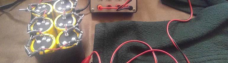
4 Electrical Energy Storage 400F * 6 at 2.7 volt supercapacitors are in series Input voltage is boosted to 17 volts Output voltage is bucked down to 5V Utilized 4 diodes as leveling circuit 7 Fabrication Process Create solar panels from solar cells Mount solar panels Prototype circuitry Build supercapacitor pack Mount and connect circuitry 8 4
5 Solar Cells Silicon Polycrystalline cells were chosen Cheaper than monocrystalline Produce less power and waste to manufacture About 17% efficiency 0.6% efficiency decay per year 0.6V open circuit voltage per cell 200mA short circuit current per cell 9 Storage Element Supercapacitors Expensive, relatively high capacity compared to normal capacitors Low no load leakage current, 0.85mA after 72 hours Can be stored for several days with usable energy Requires leveling circuit for series configuration 10 5
6 Supercapacitor Wiring diagram Pos D1 D5 D9 D2 D6 D10 D3 D4 C1 400F Supercapacitor D7 D8 C2 400F Supercapacitor D11 D12 C3 400F Supercapacitor D13 D14 D15 D16 C4 400F Supercapacitor D17 D18 D19 D20 C5 400F Supercapacitor D21 D22 D23 D24 NEG C6 400F Supercapacitor 11 Requirements Physical Requirements Functional Requirements Operational Requirements Environmental Requirements Performance Requirements 12 6
7 Circuit Design LM2678T simple switcher for buck converter 8 30 volts in, 5 volts out, max 5A LM2585 simple switcher for boost converter 4 40 volts in, max 65 volts out, 3A max output Utilized standard USB connectors for inputs and outputs 13 Boost Converter Circuit Rb2 From Solar Panels V1 5V Cb1 150µF Rb1 2.94kΩ Cb3 470nF Ub lm kΩ Rb3 19.1kΩ Lb1 68µH Db1 1N4447 Cb2 330µF Pos Neg To Supercapacitors 14 7


8 Buck Converter Circuit From Solar Panels V1 25V Cp7 15µF Cp6 15µF Cp2 15µF Cp3 10nF Cp1 0.47µF Up LM2678t Lp1 22µH Dp1 10TQ045 Cp4 180µF To Charge Medium Cp5 180µF VBUS D+ D- GND Jp1 Shell CASE1,CASE2 USB Type A 15 Supercapacitor Pack 16 8

9 Supercapacitor Pack Simulation 17 Prototype Completed on breadboard first Checked for proper voltage Transferred over to protoboard 18 9
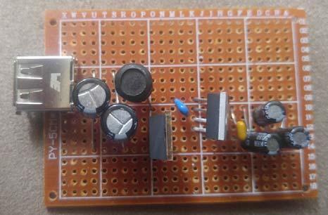
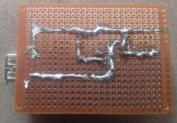


10 Protoboard Buck converter 19 Protoboard Buck/Boost Converter 20 10
11 Testing Various tests were performed through a Rheostat Tests were performed outside on the 23 of April, sunny and 68 F Solar panels without regulation circuitry Neg Voltage Current Load resistance Vsc1 Vsc2 Vsc3 Vsc4 Vsc5 Vsc6 Vsc25Vsc26Vsc27Vsc28Vsc29Vsc30 from Rheostat 0.5V 0.5V 0.5V 0.5V 0.5V 0.5V 0.5V 0.5V 0.5V 0.5V 0.5V 0.5V 10V 300mA 35Ω Vsc7 Vsc8 Vsc9 Vsc10Vsc11Vsc12 Vsc31Vsc32Vsc33Vsc34Vsc35Vsc36 12V 280mA 41Ω 0.5V 0.5V 0.5V 0.5V 0.5V 0.5V 0.5V 0.5V 0.5V 0.5V 0.5V 0.5V 24V 200mA 165Ω Vsc13Vsc14Vsc15Vsc16Vsc17Vsc18 Vsc37Vsc38Vsc39Vsc40Vsc41Vsc42 25V 170mA 193Ω 0.5V 0.5V 0.5V 0.5V 0.5V 0.5V 0.5V 0.5V 0.5V 0.5V 0.5V 0.5V 26V 130mA 260Ω Vsc19Vsc20Vsc21Vsc22Vsc23Vsc24 Vsc43Vsc44Vsc45Vsc46Vsc47Vsc48 Pos 26V 100mA 355Ω 0.5V 0.5V 0.5V 0.5V 0.5V 0.5V 0.5V 0.5V 0.5V 0.5V 0.5V 0.5V 21 Testing Buck converter testing with a current limited power supply Voltage input Current input Voltage output Current output Load resistance 25.4V 110mA 4.6V 240mA 19.7Ω 25.7V 100mA 4.7V 180mA 26.0Ω 25.4V 60mA 4.8V 150mA 32.0Ω 25.2V 40mA 4.8V 110mA 60.6Ω 25.0V 30mA 4.8V 80mA 60.6Ω 25.0V 30mA 4.9V 60mA 80.6Ω 25.3V 20mA 4.9V 40mA 123.8Ω 25.5V 10mA 4.9V 20mA 247.0Ω 22 11
12 Testing Buck converter testing with solar panels Voltage Current Load resistance from Rheostat 4.77V 150mA 30.7Ω 4.81V 110mA 41.9Ω 4.84V 90mA 54.9Ω 4.87V 60mA 80.0Ω 4.89V 40mA 125Ω 4.91V 20mA 242Ω 23 Final Integration Testing 24 12
13 Physical Requirements Requirement Data ID Requirement Requirement (Shall or Should Type statements) 6 Physical The system shall integrate solar cells onto window blinds 7 Physical The system shall have at least one USB interface 8 Physical The system shall incorporate a voltage regulation circuit The system shall store electrical 9 Physical energy in rechargeable batteries Verification Method Verification Planning Date Verified Inspection Inspection Inspection Inspection Verification Report 25 Functional Requirements Requirement Data ID Requirement Requirement (Shall or Should Type statements) The system shall capture 10 Functional solar energy with photovoltaic cells 11 Functional The system shall incorporate a buck/boost converter Verification Method Verification Planning Date Verified Inspection Inspection Verification Report 26 13
14 Operational Requirements Requirement Data ID Requirement Requirement (Shall or Should Type statements) 1 Operational The system shall capture solar energy 2 Operational The system shall convert solar energy into electrical energy The system shall store the 3 Operational captured solar energy as electrical energy 4 Operational The system shall provide a D.C. output to power a user's device 5 Operational The system should supply D.C. power via the USB interface Verification Method Verification Planning Date Verified Inspection Inspection Test Test Demonstration Verification Report 27 Environmental Requirements Requirement Data ID Requirement Requirement (Shall or Should Type statements) 18 Environmen The system shall be tal exposed to direct sunlight 19 Environmen The system shall operate between 60 and 80 degrees tal F Verification Method Verification Planning Date Verified Inspection Test Verification Report 28 14
15 Performance Requirements ID Requirement Type Requirement Data Requirement (Shall or Should statements) Verification Planning Date Verified Verification Method Verificatio n Report 12 Performance The D.C. output shall be 5V ±.5V Demonstration 4/24/ V 13 Performance 14 Performance The D.C. output shall be capable of supplying the battery with at least 200 milliamps of current The fully charged system shall be able to deliver >= 4W Test Test mA max 29 Performance Requirements Requirement Data ID Requirement Requirement (Shall or Should Type statements) The voltage regulator shall not 15 Performance exceed 100 degrees F 16 Performance 17 Performance The current shall be limited to 1.0 amps The batteries should be capable of at least 1000 mah of energy Verification Planning Date Verified Verification Method Test Test Test Verificatio n Report 300mA max 30 15

16 Cost Material/Tool Cost Item Qty Cost Each Total Cost Comments PCB board 3 $ 0.50 $ 1.50 LM2678T 2 $ 5.82 $ LM $ 6.42 $ 6.42 Resistors 4 $ 0.10 $ 0.40 Capacitors 17 $ 1.00 $ Diode 28 $ 0.54 $ Inductor 3 $ 2.00 $ 6.00 Mini blinds 1 $ $ Supercapacitor 6 $ $ Solar cell 50 $ 0.28 $ $ Material Total $ Project Management 32 16

17 Project Management 33 Original Risk Register ID Entry Date Type 1 2-Nov-16 Schedule IF 2 2-Nov-16 Technical IF 3 2-Nov-16 Technical IF 4 2-Nov-16 Technical IF 5 2-Nov-16 Cost IF 6 2-Nov-16 Cost IF 7 2-Nov-16 Schedule IF Risk Description: 'IF statement' The solar cells will take too long to acquire The current from the solar cells is too great If the solar cells are too heavy It the overcharge circuit malfunctions If my components use too much power The battery gets damaged if the overcharge system won't work THEN THEN THEN THEN THEN THEN THEN Consequence of Risk: 'THEN statement' The integration will be delayed Output current would be outside of parameters the mini blinds won't hold the cells, and won't be able to capture sunlight The battery could explode Must replace with better component Battery must be replaced it will need to be redesigned, leading to a schedule delay Status Likelihood (1-5) Severity (1-5) Score Rank* Response Open Low Mitigate Open Low Mitigate Open Low Accept Open Medium Mitigate Open Low Accept Open Medium Mitigate Open Medium Mitigate Description of Response order them asap Add a current regulating circuit Use a watchdog function to keep tabs on charging have a spare battery on hand Model the system before ordering parts 34 17


18 Risk Register Rev Risk Matrix 36 18
19 Conclusion Solar panels would work better on a mobile platform Li ion batteries would be more suitable Learned valuable information about supercapacitors Gained knowledge on solar energy 37 References Buchmann, I. (2017, Feburary 19). Bu 209: How does a Supercapacitor Work. Retrieved from Battery University: Energy, U. D. (2017, Feburary 19). Frequently Asked Question. Retrieved from U.S. Energy Information Administration: M. Ameer Ur Rehman Sheikh, M. S. (2014). Voltage Balancing of Supercapacitors String using Rectifier Diodes: Analytical and Simulation Ap proach. International Journal of Scientific & Engineering Research, Maehium, M. A. (2017, Feburary 19). The Real Lifespan of Solar Panels. Retrieved from energy informative: solar panels/ 38 19


20 Questions/Comments? 39 Demo With Li ion Battery 40 20

21 Demo With Supercapacitor Pack 41 21
QUICK START GUIDE FOR DEMONSTRATION CIRCUIT 551A-B LITHIUM-ION BATTERY CHARGER WITH CHARGE TERMINATION
 DESCRIPTION LTC4002-8.4 Demonstration circuit 551A-B is a complete constant-current/constant- voltage battery charger designed to charge a two cell Lithium-Ion Battery. Programmed for 3A charge current,
ELEC 349 Engineering Project
 Higher Colleges of Technology Al Ain Women s College ELEC 349 Engineering Project Course Code: Report Title: Project Title: ELEC 349- Integrative Project Final Technical Report Sensor-Controlled Lighting
DC Electronic Loads simulate NTC devices for temperature monitoring in battery test applications
 DC Electronic Loads simulate NTC devices for temperature monitoring in battery test applications This application note discusses the use of programmable DC loads to simulate temperature sensors used in
Data Sheet for Series and Parallel Circuits Name: Partner s Name: Date: Period/Block:
 Data Sheet for Series and Parallel Circuits Name: Partner s Name: Date: _ Period/Block: _ Build the two circuits below using two AAA or AA cells. Measure and record Voltage (Volts), Current (A), and Resistance
THE SOLAR POWERED ANTI-THEFT BAG
 THE SOLAR POWERED ANTI-THEFT BAG Ruchi Mangesh Jadhav 1, Sarika Hari Gaonkar 2, Darshan Kamlesh Khatri 3 Soumya Satish Bangera 4 a ruchimjadhav@gmail.com, b sarikagaonkar01@gmail.com, c darshankk.dk@gmail.com,
Presented at the 2012 Aerospace Space Power Workshop Manhattan Beach, CA April 16-20, 2012
 Complex Modeling of LiIon Cells in Series and Batteries in Parallel within Satellite EPS Time Dependent Simulations Presented at the 2012 Aerospace Space Power Workshop Manhattan Beach, CA April 16-20,
A Solar Power System for a Residential Application
 A Solar Power System for a Residential Application Osman N. Muneer ECET 490 Final Presentation Due: 12/18/08 Instructor: Paul I-Hai Lin, P.E. (EE) Faculty Advisor: Iskandar Hack, P.E. (EE) 1 Introduction
Battery Bank for Wind Turbine. Project Proposal Prash Ramani, Marcos Rived TA: Katherine O Kane
 Battery Bank for Wind Turbine Project Proposal Prash Ramani, Marcos Rived TA: Katherine O Kane Table of Contents: 1.0 Introduction.2 1.1 Statement of Purpose 1.1.0 Scope 1.1.1 Purpose 1.2 Objectives 1.2.1
Batteries. Alkaline - Not ideal, not enough power, expensive, not good for high drain applications.
 Batteries Fortunately, games console systems take in mains power and convert it to DC; which means we can bypass the mains and run the system directly off batteries. There are various types available:
INTERNATIONAL JOURNAL OF ELECTRICAL ENGINEERING & TECHNOLOGY (IJEET)
") INTERNATIONAL JOURNAL OF ELECTRICAL ENGINEERING & TECHNOLOGY (IJEET) Proceedings of the 2 nd International Conference on Current Trends in Engineering and Management ICCTEM -2014 ISSN 0976 6545(Print)
INTERNATIONAL JOURNAL OF ELECTRICAL ENGINEERING & TECHNOLOGY (IJEET) Proceedings of the 2 nd International Conference on Current Trends in Engineering and Management ICCTEM -2014 ISSN 0976 6545(Print)
Solar UPS Module V1. Maximum Power Point Tracking: the charger circuit
 Solar UPS Module V1 The device can serve constant uninterruptible power supply (UPS) in low consumption equipment where mains power supply could not be or is difficult to be solved. Power may come from
L, LTC, LTM, LT, Burst Mode, are registered trademarks of Linear Technology Corporation.
 DESCRIPTION Demonstration circuits 1376A-A and 1376A-B are High Efficiency USB Power Manager + Triple Step Down DC/DC featuring the LTC3555-1 and LTC3555-3 respectively. The LTC 3555-1/LTC3555-3 are highly
Armands Senfelds, Leonids Ribickis, Ansis Avotins, Peteris Apse-Apsitis
 Development of 600V Industrial DC Microgrid for Highly Automated Manufacturing Applications: Factory and Laboratory Infrastructure Experience Armands Senfelds, Leonids Ribickis, Ansis Avotins, Peteris
Solar Power for Emergency Communications
 Solar Power for Emergency Communications Dr. John A. Allocca, WB2LUA, www.wb2lua.com, April 25, 2007 Introduction When there is not any electrical power or fuel for an emergency generator, solar (photovoltaic)
LOW CARBON FOOTPRINT HYBRID BATTERY CHARGER FINAL PRESENTATION
 LOW CARBON FOOTPRINT HYBRID BATTERY CHARGER FINAL PRESENTATION Students: Blake Kennedy, Phil Thomas Advisors: Mr. Gutschlag, Dr. Huggins Date: May 1, 2008 1 PRESENTATION OUTLINE Project Overview Design
Simulation Analysis of Closed Loop Dual Inductor Current-Fed Push-Pull Converter by using Soft Switching
 Journal for Research Volume 02 Issue 04 June 2016 ISSN: 2395-7549 Simulation Analysis of Closed Loop Dual Inductor Current-Fed Push-Pull Converter by using Soft Switching Ms. Manasa M P PG Scholar Department
Design and Development of Bidirectional DC-DC Converter using coupled inductor with a battery SOC indication
 Design and Development of Bidirectional DC-DC Converter using coupled inductor with a battery SOC indication Sangamesh Herurmath #1 and Dr. Dhanalakshmi *2 # BE,MTech, EEE, Dayananda Sagar institute of
Photovoltaic and Ba.ery Primer. An Introduc6on
 Photovoltaic and Ba.ery Primer An Introduc6on Pu7ng Photovoltaic Technology to Prac6cal Use Some key vocab to discuss first: Voltage (volts) (V) Current (amperage) (I) Power (Wa.s) (P) P = IV more info:
UniverSOL Charge Station
 UniverSOL Charge Station Group 17 Jonathan German Amy Parkinson John Curristan Brock Stoops Sponsored by Motivations Environmental Renewable Energy Carbon Emissions Power Demand Power Dependency Availability
Happy Friday! Do this now:
 Happy Friday! Do this now: Take all three AA batteries out of your kit, and put (only!) two of them in the holder. (Keep the third one handy.) Take your digital multimeter out of its packaging, as well
Laboratory 2 Electronics Engineering 1270
 Laboratory 2 Electronics Engineering 1270 DC Test Equipment Purpose: This lab will introduce many of the fundamental test equipment and procedures used for verifying the operations of electrical circuits.
IJSER. Design and Implementation of SMR Based Bidirectional Laptop Adapter. Gowrinathan.M 1, DeviMaheswaran.V 2
 International Journal of Scientific & Engineering Research, Volume 5, Issue 4, April-2014 178 Design and Implementation of SMR Based Bidirectional Laptop Adapter Gowrinathan.M 1, DeviMaheswaran.V 2 Abstract:
QUICK START GUIDE FOR DEMONSTRATION CIRCUIT MHZ 3A PEAK SWITCH CURRENT MONOLITHIC STEP-DOWN CONVERTER
 DESCRIPTION QUICK START GUIDE FOR DEMONSTRATION CIRCUIT 476 Demonstration circuit 476 is a 1.25MHz 3A monolithic step-down DC/DC switching converter using the. The LT1765 features fast switching speed,
QUICK START GUIDE FOR DEMONSTRATION CIRCUIT 1061A LINEAR LI-ION BATTERY CHARGER WITH DUAL SYNCHRONOUS BUCK REGULATOR
 Demonstration circuit 1061A is a complete single cell Lithium-Ion battery charger and two synchronous buck voltage regulators with adjustable output voltages. Operating at a frequency of 2.25MHz, the regulators
Specification. Li-ion Rechargeable Battery
 Specification of Li-ion Rechargeable Battery Model No.: 18650CA-2S-3J Reported by: 陈声宇 Date: Oct,17,2013 Checked by: Approved by: Date: Date: 1. Scope This specification describes the definition, technical
POWER MANAGEMENT AND CONTROL FOR HYBRID PV/BATTERY DC MICROGRID
 International Journal of Electrical Engineering & Technology (IJEET) Volume 9, Issue 5, September-October 2018, pp. 33 41, Article ID: IJEET_09_05_004 Available online at http://www.iaeme.com/ijeet/issues.asp?jtype=ijeet&vtype=9&itype=5
Storage-less and converter-less maximum power tracking of photovoltaic cells for a nonvolatile microprocessor
 Seoul National University Storage-less and converter-less maximum power tracking of photovoltaic cells for a nonvolatile microprocessor Cong Wang, Naehyuck Chang, Y. Kim, S. Park, Yongpan Liu, Hyung Gyu
Sunseeker Sunseek Electrica Electric l a Systems 22 September 2009
 Sunseeker Electrical Systems 22 September 2009 Primary Systems There are four primary electrical systems Solar Array and Array DC to DC Converters Battery and Battery Protection System Drive Motors (Csiro)
Green Energy Bus Stop Heating System
 Green Energy Bus Stop Heating System Project Proposal Kapadia- Khabiboulline- Yifei (Sam) Teng TA: Samantha Knoll ECE 445: Senior Design Laboratory September 17, 2014 1 1.0 INTRODUCTION Table of Contents
+Denotes lead(pb)-free and RoHS compliant. JU1 JU4 4
-free and RoHS compliant. JU1 JU4 4") 19-4381; Rev 0; 11/08 General Description The MAX8844Z evaluation kit (EV kit) is a fully assembled and tested PCB for evaluating the MAX8844Z/ MAX8844Y 28V linear Li+ battery chargers. The MAX8844Z EV
19-4381; Rev 0; 11/08 General Description The MAX8844Z evaluation kit (EV kit) is a fully assembled and tested PCB for evaluating the MAX8844Z/ MAX8844Y 28V linear Li+ battery chargers. The MAX8844Z EV
KIT-STCS60D KIT-STCS100D Solar Suitcase 60W and 100W Owner s Manual
 KIT-STCS60D KIT-STCS100D Solar Suitcase 60W and 100W Owner s Manual RNG Group Inc. (Renogy) 14288 Central Ave., Suite A Chino, CA 91710 1-800-330-8678 Product Description The Renogy Solar Suitcases combine
NanoPower P31u / P31uX Datasheet Electric Power System for mission critical space applications with limited resources
 NanoPower P31u / P31uX Datasheet Electric Power System for mission critical space applications with limited resources 1 Table of Contents 1 TABLE OF CONTENTS... 2 2 OVERVIEW... 3 2.1 HIGHLIGHTED FEATURES...
+Denotes lead-free and RoHS compliant.
 19-4165; Rev 0; 6/08 MAX9921 Evaluation Kit General Description The MAX9921 evaluation kit (EV kit) is a fully assembled and tested PCB that demonstrates the capabilities of the MAX9921 dual 2-wire Hall-effect
Solar Power Energy Harvesting Electrical Integration
 WHITEPAPER Solar Power Energy Harvesting Electrical Integration Contents Introduction... 1 Solar Cell Electrical Characteristics... 2 Energy Harvesting System Topologies... 4 Design Guide... 6 Indoor Single
Solar Powered Wireless Sensors & Instrumentation
 Solar Powered Wireless Sensors & Instrumentation Energy Harvesting Technology Reduces Operating Cost at Remote Sites Speakers: Michael Macchiarelli Standards Certification Education & Training Publishing
Analysis of Grid Connected Solar Farm in ETAP Software
 ABSTRACT 2017 IJSRSET Volume 3 Issue 3 Print ISSN: 2395-1990 Online ISSN : 2394-4099 Themed Section: Engineering and Technology Analysis of Grid Connected Solar Farm in ETAP Software Komal B. Patil, Prof.
CE3211 Series. Standalone 1A Linear Lithium Battery Charger With Thermal Regulation INTRODUCTION: FEATURES: APPLICATIONS:
 Standalone 1A Linear Lithium Battery Charger With Thermal Regulation INTRODUCTION: The CE3211 is a complete constant-current/ constant-voltage linear charger for single cell lithium rechargeable battery.
Power Electronics Projects
 Power Electronics Projects I. POWER ELECTRONICS based MULTI-PORT SYSTEMS 1. Analysis, Design, Modeling, and Control of an Interleaved- Boost Full-ridge Three-Port Converter for Hybrid Renewable Energy
ECE 480 Design Team 3: Designing Low Voltage, Low Current Battery Chargers
 Michigan State University Electrical Engineering Department ECE 480 Design Team 3: Designing Low Voltage, Low Current Battery Chargers Application Note Created by: James McCormick 11/8/2015 Abstract: The
World Scientific Research Journal (WSRJ) ISSN: Multifunctional Controllable and Detachable Bicycle Power Generation /
 ISSN: Multifunctional Controllable and Detachable Bicycle Power Generation /") World Scientific Research Journal (WSRJ) ISSN: 2472-3703 www.wsr-j.org Multifunctional Controllable and Detachable Bicycle Power Generation / Charging Device Yunxia Ye School of North China Electric Power
World Scientific Research Journal (WSRJ) ISSN: 2472-3703 www.wsr-j.org Multifunctional Controllable and Detachable Bicycle Power Generation / Charging Device Yunxia Ye School of North China Electric Power
Design and Simulation of Grid Connected PV System
 Design and Simulation of Grid Connected PV System Vipul C.Rajyaguru Asst. Prof. I.C. Department, Govt. Engg. College Rajkot, Gujarat, India Abstract: In this paper, a MATLAB based simulation of Grid connected
QUICK START GUIDE FOR DEMONSTRATION CIRCUIT 1020 HIGH EFFICIENCY USB POWER MANAGER + TRIPLE STEP-DOWN DC/DC LTC3555
 DESCRIPTION Demonstration Circuit 1020 is a High Efficiency USB Power Manager + Three Step-Down DC/DC Converters featuring the LTC 3555. The LTC 3555 is a highly integrated power management and battery
Design of Three Input Buck-Boost DC-DC Converter with Constant input voltage and Variable duty ratio using MATLAB/Simulink
 Design of Three Input Buck-Boost DC-DC Converter with Constant input voltage and Variable duty ratio using MATLAB/Simulink A.Thiyagarajan, B.Gokulavasan Abstract Nowadays DC-DC converter is mostly used
PacMan BoB QA Test Plan
 PACMAN BOB QA TEST PLAN 1 PacMan BoB QA Test Plan ECE 492 Spring 2014 Latest Revision: 18 April 2014 Prepared by: Drew Jeffrey Abstract This document covers the plan of testing to ensure the Pack Manager
Product Specifications
 File No:E-SPE-1106-01 Ver: 1.0 Page: 1/ 10 Type:Polymer Li-ion Rechargeable Battery Model:DTP605068-3P Specification:3.7V/6000mAh Prepared By/Date Checked By/Date Approved By/Date Yang qin 2015/11/06 Customer
Analysis and Design of Improved Isolated Bidirectional Fullbridge DC-DC Converter for Hybrid Electric Vehicle
 Analysis and Design of Improved Isolated Bidirectional Fullbridge DC-DC Converter for Hybrid Electric Vehicle Divya K. Nair 1 Asst. Professor, Dept. of EEE, Mar Athanasius College Of Engineering, Kothamangalam,
IJSRD - International Journal for Scientific Research & Development Vol. 4, Issue 02, 2016 ISSN (online):
:") IJSRD - International Journal for Scientific Research & Development Vol. 4, Issue 02, 2016 ISSN (online): 2321-0613 Bidirectional Double Buck Boost Dc- Dc Converter Malatesha C Chokkanagoudra 1 Sagar B
IJSRD - International Journal for Scientific Research & Development Vol. 4, Issue 02, 2016 ISSN (online): 2321-0613 Bidirectional Double Buck Boost Dc- Dc Converter Malatesha C Chokkanagoudra 1 Sagar B
General Description. Features. Component List. Component Suppliers
 General Description The MAX5062A evaluation kit (EV kit) is a fully assembled and tested circuit board that demonstrates the performance of the MAX5062A 60V, 300mA ultra-small, high-efficiency, synchronous
Modelling and Control of Ultracapacitor based Bidirectional DC-DC converter systems PhD Scholar : Saichand K
 Modelling and Control of Ultracapacitor based Bidirectional DC-DC converter systems PhD Scholar : Saichand K Advisor: Prof. Vinod John Department of Electrical Engineering, Indian Institute of Science,
Solar Photovoltaic (PV) System Components
 System Components") az1742 August 2017 Solar Photovoltaic (PV) System Components Dr. Ed Franklin Introduction Solar photovoltaic (PV) energy systems are made up of different components. Each component has a specific role.
az1742 August 2017 Solar Photovoltaic (PV) System Components Dr. Ed Franklin Introduction Solar photovoltaic (PV) energy systems are made up of different components. Each component has a specific role.
A PARALLEL SNUBBER CAPACITOR BASED HIGH STEP UP ISOLATED BIDIRECTIONAL FULL BRIDGE DC TO DC CONVERTER
 Volume 115 No. 8 2017, 1-8 ISSN: 1311-8080 (printed version); ISSN: 1314-3395 (on-line version) url: http://www.ijpam.eu ijpam.eu A PARALLEL SNUBBER CAPACITOR BASED HIGH STEP UP ISOLATED BIDIRECTIONAL
Charging Battery with Clean Energy
 Charging Battery with Clean Energy By Mr. Raksapol Thananuwong Senior Academic Staff The Institute for the Promotion of Teaching Science and Technology (IPST), Thailand Raksapol Thananuwong BA in Physics
DEVELOPMENT OF LABORATORY MODULE FOR SMALL WIND TURBINE CONTROL SYSTEM
 DEVELOPMENT OF LABORATORY MODULE FOR SMALL WIND TURBINE CONTROL SYSTEM Project Plan Advisor/Client: Dr. Venkatarama Ajjarapu Achila Jayasuriya Adam Literski Eurydice Ulysses Josephine Namatovu Logeshwar
Inverter with MPPT and Suppressed Leakage Current
 POWER ELECTRONICS IEEE Projects Titles -2018 LeMeniz Infotech 36, 100 feet Road, Natesan Nagar(Near Indira Gandhi Statue and Next to Fish-O-Fish), Pondicherry-605 005 Web : www.ieeemaster.com / www.lemenizinfotech.com
Power Management Solution With 196 HVC ENYCAP TM for Mini Charger and Fixed Voltage Supply Board
 VISHAY BCCOMPONENTS www.vishay.com Aluminum Capacitors By Gerald Tatschl MAL29699003E3 96 HVC ENYCAP TM - MINI CHARGER AND BACKUP BOARD DESCRIPTION The MAL29699003E3 mini charger and backup demonstration
PART MAX1612EEE MAX1613EEE TOP VIEW BBATT LRI +3.3V +5V V CPU
 19-4785; Rev ; 11/98 EALUATION KIT MANUAL FOLLOWS DATA SHEET Bridge-Battery Backup Controllers General Description The manage the bridge battery (sometimes called a hot-swap or auxiliary battery) in portable
Application Note. DA1468x Battery Charging AN-B-035
 Application Note AN-B-035 Abstract This document describes the battery charging operation for a lithium-ion or lithium-polymer battery using the DA1468x device. Contents Abstract... 1 Contents... 2 Figures...
Modeling and Analysis of Vehicle with Wind-solar Photovoltaic Hybrid Generating System Zhi-jun Guo 1, a, Xiang-yu Kang 1, b
 4th International Conference on Sustainable Energy and Environmental Engineering (ICSEEE 015) Modeling and Analysis of Vehicle with Wind-solar Photovoltaic Hybrid Generating System Zhi-jun Guo 1, a, Xiang-yu
DesignandConstructionofaPortableChargerbyusingSolarCap
 Global Journal of Researches in Engineering: Mechanical and Mechanics Engineering Volume 17 Issue 5 Version 1.0 Type: Double Blind Peer Reviewed International Research Journal Publisher: Global Journals
RF Energy Harvesting and Battery- Free Wireless Sensors
 RF Energy Harvesting and Battery- Free Wireless Sensors Pierre Mars, VP Applications Engineering, CAP-XX Charlie Greene, Head of Technology Platforms, Powercast Darnell nanopower Forum, May 2009 Overview
International Journal Of Core Engineering & Management Volume-4, Issue-10, January-2018, ISSN No:
 IMPLEMENTATION OF SOLAR CELL INTEGRATION BUCK CONVERTER SYSTEM FOR MOBILE PHONES CHARGING Ranjit Singh Sarban Singh Centre for Telecommunication Research and Innovation (CeTRI), Faculty of Electronics
5A Synchronous Buck Li-ion Charger With Adapter Adaptive
 5A Synchronous Buck Li-ion Charger With Adapter Adaptive General Description The is a 5A Li-Ion battery charger intended for 4.4~14 wall adapters. It utilizes a high efficiency synchronous buck converter
In this installment we will look at a number of things that you can do with LEDs on your layout. These will include:
 Introduction The first article in this series, LEDs 101 - The Basics, served to review the characteristics and use of LED lighting in a garden railway environment. It also generated a host of questions
Specifications are at T A = 25 C
 Description Demonstration circuit 569 is a single cell Li-Ion linear charger in a SOT-. Charge rates as high as 600mA can be achieved due to the LTC 4054 s internal die temperature control loop that prevents
POWER SUPPLY MODEL XP-800. TWO AC VARIABLE VOLTAGES; 0-120V and 7A, PLUS UP TO 10A. Instruction Manual. Elenco Electronics, Inc.
 POWER SUPPLY MODEL XP-800 TWO AC VARIABLE VOLTAGES; 0-120V and 0-40V @ 7A, PLUS 0-28VDC @ UP TO 10A Instruction Manual Elenco Electronics, Inc. Copyright 1991 Elenco Electronics, Inc. Revised 2002 REV-I
UM0672 User manual. CRX14 and CR14 reference design PCB Gerber files. Introduction
 User manual CRX14 and CR14 reference design PCB Gerber files Introduction The purpose of this user manual is to give printed-circuit board references to ease design in the case of STMicroelectronics CRX14
Mobile Battery Charger Circuit Diagram Without Transformer
 Mobile Battery Charger Circuit Diagram Without Transformer The circuit is probably as per Andy Aka but from the photo, it does not have the If battery is 500 mah it will charge at around C/5 and if left
Project Report Cover Page
 New York State Pollution Prevention Institute R&D Program 2015-2016 Student Competition Project Report Cover Page University/College Name Team Name Team Member Names SUNY Buffalo UB-Engineers for a Sustainable
Need Uninterrupted Power? Let A Supercapacitor Come To The Rescue
 Need Uninterrupted Power? Let A Supercapacitor Come To The Rescue by Bonnie Baker, Maxim Integrated, Tucson, Ariz. ISSUE: December 2018 As every system around us is becoming more and more intelligent,
Lithium Ion Battery Charger for Solar-Powered Systems
 Lithium Ion Battery Charger for Solar-Powered Systems General Description: The is a complete constant-current /constant voltage linear charger for single cell Li-ion and Li Polymer rechargeable batteries.
Solar Powered Rechargeable Battery Pack with Controllable Voltage Output
 Solar Powered Rechargeable Battery Pack with Controllable Voltage Output ECE 445 Design Document - Spring 2018 Team 55 - Zhuohang Cheng, Zihao Zhang TA: Bryce Smith Table of Contents 1 Introduction 2 1.1
SECTION #1 - The experimental design
 Six Lemons in a Series/Parallel Charging a 4.4 Farad Capacitor, NO Load Resistor SECTION #1 - The experimental design 1a. The goal of this experiment is to see what voltage I can obtain with the lemon
Lithium Ion Medium Power Battery Design
 Bradley University Lithium Ion Medium Power Battery Design Project Proposal By: Jeremy Karrick and Charles Lau Advised by: Dr. Brian D. Huggins 12/10/2009 Introduction The objective of this project is
Performance Analysis of 40 KW Solar Photovoltaic System at DTU
 International Journal of Research and Scientific Innovation (IJRSI) Volume III, Issue VI, June 216 ISSN 2321 275 Performance Analysis of 4 KW Solar Photovoltaic System at DTU Dr. R. S. Mishra 1, Dr. J.
Evaluate: MAX17502E in TDFN Package. MAX17502E Evaluation Kit. General Description. Features. Component List
 General Description The MAX17502E evaluation kit (EV kit) provides a proven design to evaluate the MAX17502E high-efficiency, highvoltage, synchronous step-down DC-DC converter. The EV kit uses this device
DEMO MANUAL DC705A. LTC4053EMSE-4.2 Lithium-Ion Linear Battery Charger with Thermal Regulation. Description
 Description LTC405EMSE-4. Lithium-Ion Linear Battery Charger with Thermal Regulation Demonstration circuit DC705 is a complete constantcurrent, constant-voltage battery charger designed to charge one Lithium-Ion
Evaluates: MAX MAX16935 Evaluation Kit. General Description. Features and Benefits. Quick Start. Table 1. EN Configuration (JU1)
") General Description The MAX16935 evaluation kit (EV kit) demonstrates the MAX16935 high-voltage, current-mode step-down converter with low operating current. The EV kit operates over a wide 3.5V to 36V
General Description The MAX16935 evaluation kit (EV kit) demonstrates the MAX16935 high-voltage, current-mode step-down converter with low operating current. The EV kit operates over a wide 3.5V to 36V
Name: S P CHINHARA ID: K-Bank
 HYBRID SOLAR CHARGER CUM AUTOMATIC LIGHTING SYSTEM Date: 13.04.2018 Name: S P CHINHARA Email ID: spchinhara@rediffmail.com K-Bank NINL Internal Page 1 Confidentiality Statement The information in the document
A Team-based ECET Capstone Project: Design and Implementation of a Solar Insolation Measurement System
 A Team-based ECET Capstone Project: Design and Implementation of a Solar Insolation Measurement System Abstract This paper describes an example of the successful design and implementation of a Portable
Performance of Batteries in Grid Connected Energy Storage Systems. June 2018
 Performance of Batteries in Grid Connected Energy Storage Systems June 2018 PERFORMANCE OF BATTERIES IN GRID CONNECTED ENERGY STORAGE SYSTEMS Authors Laurie Florence, Principal Engineer, UL LLC Northbrook,
II. ANALYSIS OF DIFFERENT TOPOLOGIES
 An Overview of Boost Converter Topologies With Passive Snubber Sruthi P K 1, Dhanya Rajan 2, Pranav M S 3 1,2,3 Department of EEE, Calicut University Abstract This paper does the analysis of different
How to use V bee to charge other devices:
 V bee User Manual How to charge V bee: Use the attached Micro USB cable to charge V bee by connecting it to a PC or Notebook s USB port. V bee can also be charged by an external AC charger. You can use
Specification Approval Sheet
 Specification Approval Sheet Name: Model: SPEC: Approved By Checkup Make Signature Date Customer Confirmation Company Name: Stamp:, U.S.A. Tel: 510.687.0388 Fax: 510.687-0328 www.tenergybattery.com TABLE
High Altitude Balloon
 High Altitude Balloon Power Bus Development Team Todd Rogers Aoun Barki Henok Feseha June 2009 Faculty Advisors John Wu Bruce Rahn (Mentor) Balloon Setup Balloon Parachute Connection Ring Experiment Box
Reach Beyond Traditional Powering Scenarios with New Ultralow I Q Buck-Boost Converters
 Reach Beyond Traditional Powering Scenarios with New Ultralow I Q Buck-Boost Converters John Bazinet Staff Scientist Power Products David Loconto Design Center Manager Power Products Steve Knoth Senior
Ian Jones, TWI Ltd ITMA 2015, Milan
 Ian Jones, TWI Ltd ITMA 2015, Milan Powerweave FP7 European Project Development of Textiles for Electrical Energy Generation and Storage 4 years - ends in November 2015 Coordinated by TWI Ltd, UK 7 industrial
Sensor less Control of BLDC Motor using Fuzzy logic controller for Solar power Generation
 Sensor less Control of BLDC Motor using Fuzzy logic controller for Solar power Generation A. Sundaram 1 and Dr. G.P. Ramesh 2 1 Department of Electrical and Electronics Engineering, St. Peter s University,
Features. General Description. Component List
 General Description The MAX17502F evaluation kit (EV kit) provides a proven design to evaluate the MAX17502F high-efficiency, highvoltage, synchronous step-down DC-DC converter. The EV kit uses the device
THINERGY MEC220. Solid-State, Flexible, Rechargeable Thin-Film Micro-Energy Cell
 THINERGY MEC220 Solid-State, Flexible, Rechargeable Thin-Film Micro-Energy Cell DS1013 v1.1 Preliminary Product Data Sheet Features Thin Form Factor 170 µm Thick Capacity options up to 400 µah All Solid-State
Energy Harvesting Platform
 Energy Harvesting Platform Group 8 S A N JAY K H E ML A NI T R AV I S B A D A L L K I A R A R O D R I G U EZ M I C H A EL L I N EE EE EE EE Motivation Non-renewable energy sources harm the environment
EV2636-R-00A Full-Power-Management IC For Single-Cell Battery System
 Full-Power-Management IC For Single-Cell Battery System DESCRIPTION The is the evaluation board designed to demonstrate the capabilities of MPS MP2636, a highly-integrated, flexible switch-mode battery
Time-Division Multiplexed Pulsed Charging of Modular Pb-acid Battery Storage
 IOSR Journal of Electrical and Electronics Engineering (IOSR-JEEE) e-issn: 2278-1676,p-ISSN: 2320-3331, Volume 9, Issue 4 Ver. II (Jul Aug. 2014), PP 35-40 Time-Division Multiplexed Pulsed Charging of
AN-1166 Lithium Polymer Battery Charger using GreenPAK State Machine
 AN-1166 Lithium Polymer Battery Charger using GreenPAK State Machine This note describes the design of a complete charging circuit. A single cell Lithium Polymer (LiPol) battery is charged in two stages:
C C S E B. UNIVERSAL-CCS-Charger Module. for Rechargeable Batteries EVALUATION BOARD. Features of CCS-SYSTEM 1)
") C C S E B EVALUATION BOARD UNIVERSAL-CCS-Charger Module for Rechargeable Batteries Features of CCS-SYSTEM 1) Microcomputer-controlled Quick-Charge in 20-90 minutes 2) 100%-Fullcharge-Recognition, no overcharge
C C S E B EVALUATION BOARD UNIVERSAL-CCS-Charger Module for Rechargeable Batteries Features of CCS-SYSTEM 1) Microcomputer-controlled Quick-Charge in 20-90 minutes 2) 100%-Fullcharge-Recognition, no overcharge
A Electric Power / Controls ELECTRIC POWER TECHNOLOGY 0.2 kw
 A Electric Power / Controls ELECTRIC POWER TECHNOLOGY 0.2 kw TRAINING SYSTEMS, Shown with optional equipment. The production of energy using renewable natural resources such as wind, sunlight, rain, tides,
Supercapacitors as Power Buffers between Energy Harvesters and Wireless Sensors Pierre Mars Battery Power, September 18-19, 2012
 Supercapacitors as Power Buffers between Energy Harvesters and Wireless Sensors Pierre Mars Battery Power, September 18-19, 2012 Energy: The amount of work that can be done Power: The rate at which work
Photovoltaic System Design for DC House
 Photovoltaic System Design for DC House A Senior Project presented to the Faculty of the Electrical Engineering Department California Polytechnic State University, San Luis Obispo In Partial Fulfillment
AND9067/D. Solar LED Lamp Application Using the CAT4139 APPLICATION NOTE.
 Solar LED Lamp Application Using the CAT4139 INTRODUCTION Our age, characterized by the high degree of global industrialization, environmental pollutions and energy shortages, requires developing renewable
MAX16840L Evaluation Kit Evaluates: MAX16840
 19-5978; Rev 0; 7/11 MAX16840L Evaluation Kit General Description The MAX16840L low-power (5W input) evaluation kit (EV kit) demonstrates the MAX16840 HBLED driver IC used for Solid State Lighting (SSL)
SGM4056 High Input Voltage Charger
 GENERAL DESCRIPTION The SGM456 is a cost-effective, fully integrated high input voltage single-cell Li-ion battery charger. The charger uses a CC/CV charge profile required by Li-ion battery. The charger