ELEVATOR TRACTION MACHINE ASSEMBLY ARRANGEMENT ABOVE ELEVATOR COUNTERWEIGHT AND CAR
|
|
|
- Ernest Dean
- 5 years ago
- Views:
Transcription
1 1 ELEVATOR TRACTION MACHINE ASSEMBLY ARRANGEMENT ABOVE ELEVATOR COUNTERWEIGHT AND CAR This invention is specially devised in order to provide arrangement plan of an elevator traction machine above elevator counterweight and car. For a traditional elevator, it has to be considered to invest a considerable cost in the 5 construction of a machine room. This invention will provide arrangement plan of an elevator traction machine above elevator counterweight and car so that the elevator with this invention mentioned arrangement is a kind of elevator without machine room. 10 The following advantages can be achieved by applying this invention: The arrangement plan of this invention has an advantage that the cost of construction of machine room of traditional elevator can be reduced obviously. The arrangement plan of this invention has a second advantage that the space 15 machine room of traditional elevator can be saved. of 20 The arrangement plan of this invention has a third advantage that the look of top of building can be more improved because the building will not need a bulgy top for a machine room of elevator. In this invention, following schematics will help to describe this invention in detail: 25 FIG.1 presents the top plan view of the traction machine arrangement above the counterweight and car of this invention. FIG.2 presents the side plan view of the FIG.1 with an overslung roping. FIG.3 presents the other side pan view of FIG FIG.4 presents the side plan view of a second embodiment of this invention illustrating an underslung roping configuration. FIG.5 presents the top plan view of the FIG.4
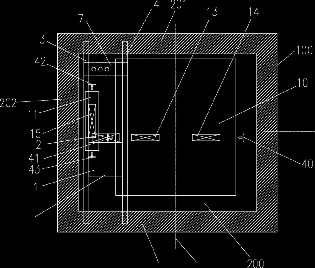
2 2 FIG.6 presents the fixing position of the traction machine which is applied in this invention. The traction machine arrangement according to this invention is presented in 5 FIGS diagrammatically. The elevator with the traction machine arrangement of this invention runs in hoistway 200 surrounded by structure 100. The structure 100 has sidewalls 201, 202, 203, At the top portion of sidewall 201, there is the support hole 5 shown in FIG.3. At the top portion of sidewall 203, there is the support hole 6 shown in FIG.3. The support hole 5 is symmetrical with the support hole 6 on the opposite sidewalls 201, The traction machine assembly 99 contains traction machine 1 with a driving sheave 2, support members 3, 4 and ropes plate 7. The traction machine 1 with a driving sheave 2 is fixed on two support members 3, 4 at the two sides of the traction machine 1 with 20 bolts. The two ends of the support members 3, 4 are located in the support holes 5, 6 of sidewall 201, 203 in the structure The projection of the traction machine assembly 99 overlaps with the projection of elevator car 10 and elevator counterweight 11. The supporting members 3, 4 are substantially parallel to the centerline 301 of the elevator car 10. The elevator car 10 is suspended by traction ropes 12 by means of car top pulleys and 14, and runs upwardly or downwardly along car guide rails 40, 41. The elevator counterweight 11 is suspended by traction ropes 12 by means of counterweight top pulley 15 and runs upwardly or downwardly along counterweight guide rails 42, 43. The number of steel traction ropes is usually at least 3.
3 3 One end of the traction ropes 12 is fixed on the ropes plate 7 of traction machine assembly 99, the other end of the traction ropes 12 is fixed on the top portion of the hoistway. As shown in FIG.2-3, the elevator car 10 is overslung. 5 The direction of the diameter of the driving sheave 2 of the machine 1 is substantially vertical to the plane between counterweight guide rails 42, FIG.4-5 presents the second embodiment of this invention illustrating an underslung roping configuration. The elevator with the traction machine arrangement of this embodiment runs in hoistway 200 surrounded by structure 100. The structure 100 has sidewalls 201, 202, 203, At the top portion of sidewall 201, there is the support hole 5 shown in FIG.5. At the top portion of sidewall 203, there is the support hole 6 shown in FIG.5. The support hole 5 is symmetrical with the support hole 6 on the opposite sidewalls 201, The traction machine assembly 99 contains traction machine 1 with a driving sheave 2, support members 3, 4 and ropes plate 7. The traction machine 1 with a driving sheave 2 is fixed on two support members 3, 4 at the two sides of the traction machine 1 with 25 bolts. The two ends of the support members 3, 4 are located in the support holes 5, 6 of sidewall 201, 203 in the structure 100. The projection of the traction machine assembly 99 overlaps with the projection of elevator car 10 and elevator counterweight 11. The supporting members 3, 4 are 30 substantially parallel to the centerline 301 of the elevator car 10.
4 4 5 The elevator car 10 is suspended by traction ropes 12 by means of pulleys 16, 17 and runs upwardly or downwardly along car guide rails 40, 41. The pulleys 16, 17 are under the elevator car. The alignment line of the pulleys 16 and 17 goes through a point directly below the gravity point of the elevator car. The elevator counterweight 11 is suspended by traction ropes 12 by means of counterweight top pulley 15 and runs upwardly or downwardly along counterweight guide rails 42, 43. The number of steel traction ropes is usually at least One end of the traction ropes 12 is fixed on the ropes plate 7 of traction machine assembly 99, the other end of the traction ropes 12 is fixed on the top portion of the hoistway. As shown in FIG.5, the elevator car 10 is underslung. The direction of the diameter of the driving sheave 2 of the machine 1 is substantially 15 vertical to the plane between counterweight guide rails 42, 43. FIG.6 shows the fixing position of the traction machine which is applied in this invention. The machine shown in FIG.6 is a kind of gearless machine. On the opposite sides of the 20 machine, thread holes 66 are used to connect the traction machine to the support members 3, 4. The Claims defining the invention are as follows: Elevator traction machine assembly arrangement comprising a traction machine assembly positioned above elevator counterweight and car in a hoistway with surrounded structure. 2. Elevator traction machine assembly arrangement as defined in claim 1, wherein the 30 traction machine assembly is positioned on the top portion of the hoistway by positioning the ends of the traction machine assembly in the support holes of two opposite sidewalls of the hoistway. The support holes of two opposite sidewalls are symmetrical and at the top portion of the sidewalls.
5 1/6 3. Elevator traction machine assembly arrangement as defined in claim 1 and 2, wherein the support members of traction machine assembly are substantially parallel to the one of the centerlines of the elevator car. The projection of the elevator traction machine assembly overlaps the projection of the elevator car and 5 the projection of the elevator counterweight Elevator traction machine assembly arrangement as defined in claim 1 2 and 3, wherein the direction of the diameter of the driving sheave 2 of the machine 1 is substantially vertical to the plane between counterweight guide rails 42, Elevator traction machine assembly arrangement as defined in claim 1, 2 and 3, wherein the traction machine is fixed between support members of traction machine assembly. One end of the traction ropes is fixed to the rope plate on the traction machine assembly. 6. Elevator traction machine assembly arrangement according to any one of preceding claims, wherein the elevator car is suspended by traction ropes using at least one pulley on the top of the elevator car. 7. Elevator traction machine assembly arrangement according to any one of preceding claims, wherein the elevator car is suspended by traction ropes using pulleys under the elevator car. The alignment line of the pulleys goes through a point directly below the gravity point of the elevator car. George Choate (Name of Applicant(s)) (Date)
6 2/6 FIG.1
7 3/6 FIG.2
8 4/6 FIG.3
9 5/6 FIG.4

10 6/6 FIG.5
11 7/ FIG.6
AUSTAND CH-3000 MRL HOME/RESIDENTAIL LIFTS HOME LIFT TRACTION MACHINE ASSEMBLY MOUNTED ON THE RAILS OF HOME LIFT COUNTERWEIGHT AND CAR
 1 AUSTAND CH-3000 MRL HOME/RESIDENTAIL LIFTS HOME LIFT TRACTION MACHINE ASSEMBLY MOUNTED ON THE RAILS OF HOME LIFT COUNTERWEIGHT AND CAR This invention is specially devised in order to provide arrangement
TEPZZ 6 6 8_A_T EP A1 (19) (11) EP A1 (12) EUROPEAN PATENT APPLICATION. (51) Int Cl.:
 (11) EP A1 (12) EUROPEAN PATENT APPLICATION. (51) Int Cl.:") (19) TEPZZ 6 6 8_A_T (11) EP 2 626 281 A1 (12) EUROPEAN PATENT APPLICATION (43) Date of publication: 14.08.2013 Bulletin 2013/33 (1) Int Cl.: B62D 3/00 (2006.01) (21) Application number: 1214679.0 (22)
(19) TEPZZ 6 6 8_A_T (11) EP 2 626 281 A1 (12) EUROPEAN PATENT APPLICATION (43) Date of publication: 14.08.2013 Bulletin 2013/33 (1) Int Cl.: B62D 3/00 (2006.01) (21) Application number: 1214679.0 (22)
ADJUSTABLE PEDAL ASSEMBLY WITH ELECTRONIC THROTTLE CONTROL RELATED APPLICATION. filed Jan. 26, 1999, U.S. Pat. No. 6,109,241.
 ADJUSTABLE PEDAL ASSEMBLY WITH ELECTRONIC THROTTLE CONTROL RELATED APPLICATION [0001] This application is a continuation of application Ser. No. 09/236,975, filed Jan. 26, 1999, U.S. Pat. No. 6,109,241.
(12) Patent Application Publication (10) Pub. No.: US 2006/ A1
 Patent Application Publication (10) Pub. No.: US 2006/ A1") US 20060066075A1 (19) United States (12) Patent Application Publication (10) Pub. No.: US 2006/0066075A1 Zlotkowski (43) Pub. Date: Mar. 30, 2006 (54) TOWING TRAILER FOR TWO OR THREE Publication Classification
US 20060066075A1 (19) United States (12) Patent Application Publication (10) Pub. No.: US 2006/0066075A1 Zlotkowski (43) Pub. Date: Mar. 30, 2006 (54) TOWING TRAILER FOR TWO OR THREE Publication Classification
Your interest is appreciated and hope the next 37 pages offers great profit potential for your new business. Copyright 2017 Frank Seghezzi
 Description and comparison of the ultimate new power source, from small engines to power stations, which should be of interest to Governments the general public and private Investors Your interest is appreciated
(12) United States Patent
 United States Patent") US008307952B2 (12) United States Patent Fargo et al. (10) Patent No.: (45) Date of Patent: Nov. 13, 2012 (54) ELEVATORSYSTEM WITH MULTIPLE CARS NA HOSTWAY (75) Inventors: Richard N. Fargo, Plainville,
US008307952B2 (12) United States Patent Fargo et al. (10) Patent No.: (45) Date of Patent: Nov. 13, 2012 (54) ELEVATORSYSTEM WITH MULTIPLE CARS NA HOSTWAY (75) Inventors: Richard N. Fargo, Plainville,
2,376,968. May 29, F. M. JONES TWO-CYCLE GAS ENGINE. 2 Sheets-Sheet li. Filed Dec. 26, 1942 FIG, vucinto FREDERICK M. JONES.
 May 29, 1945. F. M. JONES Filed Dec. 26, 1942 2 Sheets-Sheet li 7. FIG, 8??? ///?/ ( vucinto FREDERICK M. JONES ( Cltt May 29, 1945. F. M. JONES Filed Dec. 26, 1942 2. Sheets-Sheet 2 48 aa FG. 2 35 21
(12) Patent Application Publication (10) Pub. No.: US 2014/ A1
 Patent Application Publication (10) Pub. No.: US 2014/ A1") (19) United States US 20140224,592A1 (12) Patent Application Publication (10) Pub. No.: US 2014/0224.592 A1 VALJUS et al. (43) Pub. Date: (54) ELEVATOR (71) Applicant: KONE CORPORATION, Helsinki (FI) (72)
(19) United States US 20140224,592A1 (12) Patent Application Publication (10) Pub. No.: US 2014/0224.592 A1 VALJUS et al. (43) Pub. Date: (54) ELEVATOR (71) Applicant: KONE CORPORATION, Helsinki (FI) (72)
TEPZZ ZZ _A_T EP A1 (19) (11) EP A1 (12) EUROPEAN PATENT APPLICATION. (51) Int Cl.: F28F 3/10 ( ) F28F 3/08 (2006.
 (11) EP A1 (12) EUROPEAN PATENT APPLICATION. (51) Int Cl.: F28F 3/10 ( ) F28F 3/08 (2006.") (19) TEPZZ ZZ _A_T (11) EP 3 001 131 A1 (12) EUROPEAN PATENT APPLICATION (43) Date of publication:.03.16 Bulletin 16/13 (1) Int Cl.: F28F 3/ (06.01) F28F 3/08 (06.01) (21) Application number: 1418664.2
(19) TEPZZ ZZ _A_T (11) EP 3 001 131 A1 (12) EUROPEAN PATENT APPLICATION (43) Date of publication:.03.16 Bulletin 16/13 (1) Int Cl.: F28F 3/ (06.01) F28F 3/08 (06.01) (21) Application number: 1418664.2
Europaisches Patentamt (19) J. European Patent Office Office europeen des brevets (11) EP A2 (12) EUROPEAN PATENT APPLICATION
 J. European Patent Office Office europeen des brevets (11) EP A2 (12) EUROPEAN PATENT APPLICATION") (19) J Europaisches Patentamt European Patent Office Office europeen des brevets (11) EP 0 885 802 A2 (12) EUROPEAN PATENT APPLICATION (43) Date of publication: (51) int. CI.6: B62M 23/02 23.12.1998 Bulletin
(19) J Europaisches Patentamt European Patent Office Office europeen des brevets (11) EP 0 885 802 A2 (12) EUROPEAN PATENT APPLICATION (43) Date of publication: (51) int. CI.6: B62M 23/02 23.12.1998 Bulletin
12) United States Patent 10) Patent No.: US 6, B1
 United States Patent 10) Patent No.: US 6, B1") USOO6397974B1 12) United States Patent 10) Patent No.: US 6,397.974 B1 9 9 Adlifon et al. (45) Date of Patent: *Jun. 4, 2002 (54) TRACTION ELEVATOR SYSTEM USING 5,018,603 A 5/1991 Ito... 187/17 FLEXIBLE,
USOO6397974B1 12) United States Patent 10) Patent No.: US 6,397.974 B1 9 9 Adlifon et al. (45) Date of Patent: *Jun. 4, 2002 (54) TRACTION ELEVATOR SYSTEM USING 5,018,603 A 5/1991 Ito... 187/17 FLEXIBLE,
United States Patent (19) Cronk et al.
 Cronk et al.") United States Patent (19) Cronk et al. (S4) LANDING GEAR FOR ULTRALIGHT AIRCRAFT 76) Inventors: David Cronk, 1069 Eucalyptus Ave., Vista, Calif. 92025; Lyle M. Byrum, 1471 Calle Redonda, Escondido, Calif.
United States Patent (19) Cronk et al. (S4) LANDING GEAR FOR ULTRALIGHT AIRCRAFT 76) Inventors: David Cronk, 1069 Eucalyptus Ave., Vista, Calif. 92025; Lyle M. Byrum, 1471 Calle Redonda, Escondido, Calif.
United States Patent (19) Miller, Sr.
 Miller, Sr.") United States Patent (19) Miller, Sr. 11 Patent Number: 5,056,448 (45) Date of Patent: Oct. 15, 1991 (54) (76. (21) (22) 51 (52) (58) PVC BOAT Inventor: Terry L. Miller, Sr., P.O. Box 162, Afton, Okla.
United States Patent (19) Miller, Sr. 11 Patent Number: 5,056,448 (45) Date of Patent: Oct. 15, 1991 (54) (76. (21) (22) 51 (52) (58) PVC BOAT Inventor: Terry L. Miller, Sr., P.O. Box 162, Afton, Okla.
PATENT: ARTICULATED RHOMBIC PRISM PISTON FOR THERMAL MACHINES Filed in Italy on 18/11/2008 N TO 2008 A Inventor: Vittorio Scialla -
 PATENT: ARTICULATED RHOMBIC PRISM PISTON FOR THERMAL MACHINES Filed in Italy on 18/11/2008 N TO 2008 A 000847 Inventor: Vittorio Scialla - Nationality: italian - Resident: Via Cibrario 114, Torino (TO),
(51) Int. Cl."... B62B 7700
 Int. Cl.... B62B 7700") US006062577A United States Patent (19) 11 Patent Number: 6,062,577 Tan (45) Date of Patent: May 16, 2000 54) QUICK CLICK BRAKE AND SWIVEL 56) References Cited SYSTEM U.S. PATENT DOCUMENTS 76 Inventor:
US006062577A United States Patent (19) 11 Patent Number: 6,062,577 Tan (45) Date of Patent: May 16, 2000 54) QUICK CLICK BRAKE AND SWIVEL 56) References Cited SYSTEM U.S. PATENT DOCUMENTS 76 Inventor:
United States Patent (19)
") United States Patent (19) Fujita 11 Patent Number: (45) Date of Patent: 4,727,957 Mar. 1, 1988 (54) RUBBER VIBRATION ISOLATOR FOR MUFFLER 75 Inventor: Akio Fujita, Fujisawa, Japan 73) Assignee: Bridgestone
United States Patent (19) Fujita 11 Patent Number: (45) Date of Patent: 4,727,957 Mar. 1, 1988 (54) RUBBER VIBRATION ISOLATOR FOR MUFFLER 75 Inventor: Akio Fujita, Fujisawa, Japan 73) Assignee: Bridgestone
(12) United States Patent (10) Patent No.: US 6,469,466 B1
 United States Patent (10) Patent No.: US 6,469,466 B1") USOO6469466B1 (12) United States Patent (10) Patent No.: US 6,469,466 B1 Suzuki (45) Date of Patent: Oct. 22, 2002 (54) AUTOMATIC GUIDED VEHICLE JP 7-2S1768 10/1995 JP 8-1553 1/1996 (75) Inventor: Takayuki
USOO6469466B1 (12) United States Patent (10) Patent No.: US 6,469,466 B1 Suzuki (45) Date of Patent: Oct. 22, 2002 (54) AUTOMATIC GUIDED VEHICLE JP 7-2S1768 10/1995 JP 8-1553 1/1996 (75) Inventor: Takayuki
Feb. 14, 1967 R. B. WENGER 3,304,094 CLIMBING WHEEL CHAIR A/C. Z. 5 is INVENTOR. a/caezo as a 7/gate, 57 d. 2. XO aoz. 1277aatavays.
 Feb. 14, 1967 R. B. WENGER CLIMBING WHEEL CHAIR Filed Dec. 22, 1964 3. Sheets-Sheet A/C. Z. is INVENTOR. a/caezo as a 7/gate, BY 7 d. 2. XO-4-2. 32427 aoz 1277aatavays. Feb. 14, 1967 R. B. WENGER CLIMBING
United States Patent (19) Hensler
 Hensler") United States Patent (19) Hensler 54 AERIAL BOOM WITH TENSIOMETER 75) Inventor: David Hensler, Fort Wayne, Ind. 73) Assignee: Hydra-Tech, Inc., Ft. Wayne, Ind. (21) Appl. No.: 35,536 (22 Filed: Apr. 7,
United States Patent (19) Hensler 54 AERIAL BOOM WITH TENSIOMETER 75) Inventor: David Hensler, Fort Wayne, Ind. 73) Assignee: Hydra-Tech, Inc., Ft. Wayne, Ind. (21) Appl. No.: 35,536 (22 Filed: Apr. 7,
(12) Patent Application Publication (10) Pub. No.: US 2004/ A1
 Patent Application Publication (10) Pub. No.: US 2004/ A1") (19) United States (12) Patent Application Publication (10) Pub. No.: Glance et al. US 20040183344A1 (43) Pub. Date: Sep. 23, 2004 (54) (76) (21) (22) (60) (51) SEAT ENERGY ABSORBER Inventors: Patrick
(19) United States (12) Patent Application Publication (10) Pub. No.: Glance et al. US 20040183344A1 (43) Pub. Date: Sep. 23, 2004 (54) (76) (21) (22) (60) (51) SEAT ENERGY ABSORBER Inventors: Patrick
(12) Patent Application Publication (10) Pub. No.: US 2003/ A1
 Patent Application Publication (10) Pub. No.: US 2003/ A1") US 2003O190837A1 (19) United States (12) Patent Application Publication (10) Pub. No.: US 2003/0190837 A1 W (43) Pub. Date: Oct. 9, 2003 (54) BATTERY HOLDER HAVING MEANS FOR (52) U.S. Cl.... 439/500 SECURELY
US 2003O190837A1 (19) United States (12) Patent Application Publication (10) Pub. No.: US 2003/0190837 A1 W (43) Pub. Date: Oct. 9, 2003 (54) BATTERY HOLDER HAVING MEANS FOR (52) U.S. Cl.... 439/500 SECURELY
Multilayer Energy Dissipating Inlet Column in Center-Feed Clarifiers 1
 Multilayer Energy Dissipating Inlet Column in Center-Feed Clarifiers 1 References 6,276,537 08/21/2001 Esler et al 210/519 6,800,209 10/05/2004 Wright 210/801 Field of Invention Clarifiers are tanks where
(12) Patent Application Publication (10) Pub. No.: US 2014/ A1. Miller (43) Pub. Date: May 22, 2014
 Patent Application Publication (10) Pub. No.: US 2014/ A1. Miller (43) Pub. Date: May 22, 2014") (19) United States US 20140138340A1 (12) Patent Application Publication (10) Pub. No.: US 2014/0138340 A1 Miller (43) Pub. Date: May 22, 2014 (54) OVERHEAD HOIST (52) U.S. Cl. CPC. B66D I/34 (2013.01);
(19) United States US 20140138340A1 (12) Patent Application Publication (10) Pub. No.: US 2014/0138340 A1 Miller (43) Pub. Date: May 22, 2014 (54) OVERHEAD HOIST (52) U.S. Cl. CPC. B66D I/34 (2013.01);
April 2, 1968 O. BE TRAM 3,375,595 SINGLE BUCKET EXCAVATOR 12 INVENTOR. OS M A NO BE L T R A N. "I'llur awl ov. 4-wa
 April 2, 1968 O. BE TRAM SINGLE BUCKET EXCAVATOR Filed April 27, 1965 2. Sheets-Sheet 12 INVENTOR. OS M A NO BE L T R A N "I'llur awl ov 4-wa April 2, 1968 O. BELTRAM SINGLE EUCKET EXCAVATOR Filed April
Dec. 3, G. H. LELAND 1,737,595 ELECTRIC MOTOR W/a Av/2Ap. 2-2, 3 3 6AOAGAA. l. E/A/VD. 4772A/VAy
 Dec. 3, 1929. G. H. LELAND 1,737,595 ELECTRIC MOTOR. Filed Sept. 20, 1926 2 Sheets-Sheet - - - - - - 9. -- W/a Av/2Ap. 3 3 6AOAGAA. l. E/A/VD. 2-2, 4772A/VAy Dec. 3, 1929. G. H. LELAND 1,737,595 ELECTRIC
TEPZZ 6Z7 _6A_T EP A1 (19) (11) EP A1 (12) EUROPEAN PATENT APPLICATION. (43) Date of publication: Bulletin 2013/26
 (11) EP A1 (12) EUROPEAN PATENT APPLICATION. (43) Date of publication: Bulletin 2013/26") (19) TEPZZ 6Z7 _6A_T (11) EP 2 607 216 A1 (12) EUROPEAN PATENT APPLICATION (43) Date of publication: 26.06.2013 Bulletin 2013/26 (51) Int Cl.: B62D 55/21 (2006.01) (21) Application number: 13160462.1 (22)
(19) TEPZZ 6Z7 _6A_T (11) EP 2 607 216 A1 (12) EUROPEAN PATENT APPLICATION (43) Date of publication: 26.06.2013 Bulletin 2013/26 (51) Int Cl.: B62D 55/21 (2006.01) (21) Application number: 13160462.1 (22)
43.4cule?o (26-12% Dec. 28, V. HAMMAR ET AL 2,103,670 WHEELED FIREARM. Z-1 ule 772 or /eta A?at 777-r. Filed Nov. 23,
 Dec. 28, 1937. V. HAMMAR ET AL WHEELED FIREARM Filed Nov. 23, 19 4. Sheets-Sheet 1 n Z-1 ule 772 or /eta A?at 777-r t & 4' arran well. Werts 77 42tter Ala. e 77 43.4cule?o (26-12% Dec. 28, 1937. W. HAMMAR
~ mi mi ii mi ii imiii i ii ii i ii European Patent Office Office europeen des brevets (11) EP A1 EUROPEAN PATENT APPLICATION
 EP A1 EUROPEAN PATENT APPLICATION") (19) J (12) ~ mi mi ii mi ii imiii i ii ii i ii European Patent Office Office europeen des brevets (11) EP 0 770 762 A1 EUROPEAN PATENT APPLICATION (43) Date of publication: (51) Int. CI.6: F01 L 1/14,
(19) J (12) ~ mi mi ii mi ii imiii i ii ii i ii European Patent Office Office europeen des brevets (11) EP 0 770 762 A1 EUROPEAN PATENT APPLICATION (43) Date of publication: (51) Int. CI.6: F01 L 1/14,
and Crew LLP Mar. 4, 1999 (DE) Int. Cl."... GO2N 11/06
 Int. Cl.... GO2N 11/06") (1) United States Patent Raffer USOO64O77OB1 (10) Patent No.: (45) Date of Patent: Jun. 5, 001 (54) ROTARY VISCOSIMETER (75) Inventor: Gerhard Raffer, Graz (AT) (73) Assignee: Anton Paar GmbH, Graz (AT)
(1) United States Patent Raffer USOO64O77OB1 (10) Patent No.: (45) Date of Patent: Jun. 5, 001 (54) ROTARY VISCOSIMETER (75) Inventor: Gerhard Raffer, Graz (AT) (73) Assignee: Anton Paar GmbH, Graz (AT)
(12) United States Patent (10) Patent N0.: US 6,439,129 B2
 United States Patent (10) Patent N0.: US 6,439,129 B2") US006439129B2 (12) United States Patent (10) Patent N0.: US 6,439,129 B2 Begotti (45) Date of Patent: Aug. 27, 2002 (54) LAUNCHING SYSTEM FOR PASSENGER (56) References Cited UNITS IN EQUIPMENTS FOR AMUSEMENT
US006439129B2 (12) United States Patent (10) Patent N0.: US 6,439,129 B2 Begotti (45) Date of Patent: Aug. 27, 2002 (54) LAUNCHING SYSTEM FOR PASSENGER (56) References Cited UNITS IN EQUIPMENTS FOR AMUSEMENT
-2. A 2-2. June 8, 1965 J. R. MOOREHEAD 3,188,025 MEANS FOR TAKE-OFF, CRUISE, AND ANDING OF SUBSONIC AND SUPERSONIC AIRCRAFT. Va/Was Me.
 June 8, 1965 J. R. MOOREHEAD MEANS FOR TAKE-OFF, CRUISE, AND ANDING OF SUBSONIC AND SUPERSONIC AIRCRAFT Filed Aug. 29, 1963 3. Sheets-Sheet INVENTOR. Va/Was Me. Mooa A12-2. A 2-2 aafay7 June 8, 1965 J.
(12) Patent Application Publication (10) Pub. No.: US 2012/ A1. Underbakke et al. (43) Pub. Date: Jun. 28, 2012
 Patent Application Publication (10) Pub. No.: US 2012/ A1. Underbakke et al. (43) Pub. Date: Jun. 28, 2012") US 2012O163742A1 (19) United States (12) Patent Application Publication (10) Pub. No.: US 2012/0163742 A1 Underbakke et al. (43) Pub. Date: Jun. 28, 2012 (54) AXIAL GAS THRUST BEARING FOR (30) Foreign
US 2012O163742A1 (19) United States (12) Patent Application Publication (10) Pub. No.: US 2012/0163742 A1 Underbakke et al. (43) Pub. Date: Jun. 28, 2012 (54) AXIAL GAS THRUST BEARING FOR (30) Foreign
(12) Patent Application Publication (10) Pub. No.: US 2015/ A1
 Patent Application Publication (10) Pub. No.: US 2015/ A1") US 20150292.498A1 (19) United States (12) Patent Application Publication (10) Pub. No.: US 2015/0292498A1 Williams (43) Pub. Date: Oct. 15, 2015 (54) OIL PUMPINGAPPARATUS INCLUDING A (52) U.S. Cl. CYCLOIDAL
US 20150292.498A1 (19) United States (12) Patent Application Publication (10) Pub. No.: US 2015/0292498A1 Williams (43) Pub. Date: Oct. 15, 2015 (54) OIL PUMPINGAPPARATUS INCLUDING A (52) U.S. Cl. CYCLOIDAL
Liftcrane Boom Capacities 2250 SERIES 3
 Liftcrane Capacities 2250 SERIES 3 No. 44 With Long Reach Top LIFTING CAPACITIES: Lifting capacities for various boom lengths and operating radii are for freely suspended loads and do not exceed 75% of
NOTICE. The above identified patent application is available for licensing. Requests for information should be addressed to:
 Serial Number 09/652.305 Filing Date 20 August 2000 Inventor Antoniko M. Amaral Stanley J. Olson NOTICE The above identified patent application is available for licensing. Requests for information should
"(2.4% May 4, 1954 C. A. GUSTAFSON 2,677,202. Filed April 3, l95l AND EJECTOR OF EARTH-MOWING SCRAPERS 3. Sheets-Sheet CAR. A.
 May 4, 1954 C. A. GUSTAFSON 2,677,202 HYDRAULIC ACTUATOR FOR OPERATING THE APRON Filed April 3, l95l AND EJECTOR OF EARTH-MOWING SCRAPERS 3. Sheets-Sheet INVENTOR, CAR. A. G2/S7AASOM/ "(2.4%. 2.-- ATTORME,
NOTICE. The above identified patent application is available for licensing. Requests for information should be addressed to:
 Se rial Number 954.885 Filing Date 9 October 1997 Inventor Paul E. Moodv NOTICE The above identified patent application is available for licensing. Requests for information should be addressed to: OFFICE
*EP A1* EP A1 (19) (11) EP A1 (12) EUROPEAN PATENT APPLICATION. (43) Date of publication: Bulletin 2005/41
 (11) EP A1 (12) EUROPEAN PATENT APPLICATION. (43) Date of publication: Bulletin 2005/41") (19) Europäisches Patentamt European Patent Office Office européen des brevets *EP001585051A1* (11) EP 1 585 051 A1 (12) EUROPEAN PATENT APPLICATION (43) Date of publication: 12.10.2005 Bulletin 2005/41
(19) Europäisches Patentamt European Patent Office Office européen des brevets *EP001585051A1* (11) EP 1 585 051 A1 (12) EUROPEAN PATENT APPLICATION (43) Date of publication: 12.10.2005 Bulletin 2005/41
ll lllllllllllllllllllllllllllllllillllllllllllllllllllllllllllllllllllll
 United States Patent [191 Kaster et al. ll lllllllllllllllllllllllllllllllillllllllllllllllllllllllllllllllllllll USOO5529455A [11] Patent Number: 5,529,455 [45] Date of Patent: Jun. 25, 1996 [54] [75]
(12) Patent Application Publication (10) Pub. No.: US 2009/ A1
 Patent Application Publication (10) Pub. No.: US 2009/ A1") (19) United States US 20090045655A1 (12) Patent Application Publication (10) Pub. No.: US 2009/0045655A1 Willard et al. (43) Pub. Date: Feb. 19, 2009 (54) MULTI-PANEL PANORAMIC ROOF MODULE (75) Inventors:
(19) United States US 20090045655A1 (12) Patent Application Publication (10) Pub. No.: US 2009/0045655A1 Willard et al. (43) Pub. Date: Feb. 19, 2009 (54) MULTI-PANEL PANORAMIC ROOF MODULE (75) Inventors:
(12) United States Patent (10) Patent No.: US 6,484,362 B1
 United States Patent (10) Patent No.: US 6,484,362 B1") USOO648.4362B1 (12) United States Patent (10) Patent No.: US 6,484,362 B1 Ku0 (45) Date of Patent: Nov. 26, 2002 (54) RETRACTABLE HANDLE ASSEMBLY WITH 5,692,266 A 12/1997 Tsai... 16/113.1 MULTIPLE ENGAGING
USOO648.4362B1 (12) United States Patent (10) Patent No.: US 6,484,362 B1 Ku0 (45) Date of Patent: Nov. 26, 2002 (54) RETRACTABLE HANDLE ASSEMBLY WITH 5,692,266 A 12/1997 Tsai... 16/113.1 MULTIPLE ENGAGING
(12) United States Patent (10) Patent No.: US 6,253,701 B1
 United States Patent (10) Patent No.: US 6,253,701 B1") USOO6253701B1 (12) United States Patent (10) Patent No.: US 6,253,701 B1 Dale (45) Date of Patent: Jul. 3, 2001 (54) ANCHORING DEVICE (56) References Cited (75) Inventor: Olav Dale, Akersberga (SE) U.S.
USOO6253701B1 (12) United States Patent (10) Patent No.: US 6,253,701 B1 Dale (45) Date of Patent: Jul. 3, 2001 (54) ANCHORING DEVICE (56) References Cited (75) Inventor: Olav Dale, Akersberga (SE) U.S.
May 13, 1958 L. NEXON 2,834,302 SELF-PROPELLING AERIAL TRAMWAY CAR Filed April 30, Sheets-Sheet 1
 May 13, 1958 L. NEXON 2,834,302 SELF-PROPELLING AERIAL TRAMWAY CAR Filed April 30, 1954 4. Sheets-Sheet 1 May 13, 1958 vn L. NXON 2,834,302 SELF-PROPELLING AERIAL TRAMWAY CAR Filed April 30, l954 l4 Sheets-Sheet
(12) United States Patent (10) Patent No.: US 9,168,973 B2
 United States Patent (10) Patent No.: US 9,168,973 B2") US009 168973B2 (12) United States Patent (10) Patent No.: US 9,168,973 B2 Offe (45) Date of Patent: Oct. 27, 2015 (54) MOTORCYCLE SUSPENSION SYSTEM (56) References Cited (71) Applicant: Andrew Offe, Wilunga
US009 168973B2 (12) United States Patent (10) Patent No.: US 9,168,973 B2 Offe (45) Date of Patent: Oct. 27, 2015 (54) MOTORCYCLE SUSPENSION SYSTEM (56) References Cited (71) Applicant: Andrew Offe, Wilunga
(12) United States Patent
 United States Patent") (12) United States Patent USOO8544708B2 (10) Patent No.: US 8,544,708 B2 Maimin (45) Date of Patent: Oct. 1, 2013 (54) FOLDING PICK-UP TRUCK TOOL BOX (56) References Cited (76) Inventor: Julian Maimin,
(12) United States Patent USOO8544708B2 (10) Patent No.: US 8,544,708 B2 Maimin (45) Date of Patent: Oct. 1, 2013 (54) FOLDING PICK-UP TRUCK TOOL BOX (56) References Cited (76) Inventor: Julian Maimin,
(12) Patent Application Publication (10) Pub. No.: US 2007/ A1
 Patent Application Publication (10) Pub. No.: US 2007/ A1") (19) United States US 20070158933A1 (12) Patent Application Publication (10) Pub. No.: Siemiantkowski (43) Pub. Date: Jul. 12, 2007 (54) WHIPLASH PROTECTIONSTRUCTURE Publication Classification (51) Int.
(19) United States US 20070158933A1 (12) Patent Application Publication (10) Pub. No.: Siemiantkowski (43) Pub. Date: Jul. 12, 2007 (54) WHIPLASH PROTECTIONSTRUCTURE Publication Classification (51) Int.
United States Patent 19 [11] Patent Number: 4,877,983 Johnson (45) Date of Patent: Oct 31, 1989
![United States Patent 19 [11] Patent Number: 4,877,983 Johnson (45) Date of Patent: Oct 31, 1989](/thumbs/80/81257393.jpg "United States Patent 19 [11] Patent Number: 4,877,983 Johnson (45) Date of Patent: Oct 31, 1989") United States Patent 19 [11] Patent Number: 4,877,983 Johnson (45) Date of Patent: Oct 31, 1989 54 MAGNETICFORCE GENERATING 56 References Cited METHOD AND APPARATUS U.S. PATENT DOCUMENTS 4,074,153 2/1978
United States Patent 19 [11] Patent Number: 4,877,983 Johnson (45) Date of Patent: Oct 31, 1989 54 MAGNETICFORCE GENERATING 56 References Cited METHOD AND APPARATUS U.S. PATENT DOCUMENTS 4,074,153 2/1978
(12) United States Patent (10) Patent No.: US 7,911,096 B2
 United States Patent (10) Patent No.: US 7,911,096 B2") USOO791 1096B2 (12) United States Patent (10) Patent No.: Froelich 45) Date of Patent: Mar. 22, 2011 9 (54) ELECTROMAGNETIC OSCILLATOR WITH R. 3. A : 8. 3. yard 39. J. W-1 Clder.............................
USOO791 1096B2 (12) United States Patent (10) Patent No.: Froelich 45) Date of Patent: Mar. 22, 2011 9 (54) ELECTROMAGNETIC OSCILLATOR WITH R. 3. A : 8. 3. yard 39. J. W-1 Clder.............................
in service THE ELEVATOR THAT YOU PLUG IN LIKE A DOMESTIC APPLIANCE
 in service THE ELEVATOR THAT YOU PLUG IN LIKE A DOMESTIC APPLIANCE Guarantee of quality In 1853 OTIS created the first safe elevator in history; ever since then we have always been the world leaders in
(12) Patent Application Publication (10) Pub. No.: US 2005/ A1
 Patent Application Publication (10) Pub. No.: US 2005/ A1") US 2005O25344-4A1 (19) United States (12) Patent Application Publication (10) Pub. No.: US 2005/0253444 A1 Godshaw et al. (43) Pub. Date: Nov. 17, 2005 (54) AUTOMOBILE PET BED CONSTRUCTION (22) Filed:
US 2005O25344-4A1 (19) United States (12) Patent Application Publication (10) Pub. No.: US 2005/0253444 A1 Godshaw et al. (43) Pub. Date: Nov. 17, 2005 (54) AUTOMOBILE PET BED CONSTRUCTION (22) Filed:
Sept. 20, 1971 L, A, CHESHER 3,606,112 RETRACTABLE BEVERAGE HOLDER FOR MOTOR WEHICLES. "Ne ) h \ 23. es/fs-s. Fig. 2 E3 2 (2S, Si. N.
 h \ 23. es/fs-s. Fig. 2 E3 2 (2S, Si. N.") Sept. 20, 1971 L, A, CHESHER Filed Jan. 28, 1970 3 Sheets-Sheet Hi (1. s A. 2 Wrze "Ne ) h \ 23 3f he W \, SC-3/ es/fs-s 32 33 Fig. 7 3? Y62 - - a 2 E3 2 (2S, Si Y N. aa 24 - - - - - -9 1-- //W/EW7OA Leonord
Sept. 20, 1971 L, A, CHESHER Filed Jan. 28, 1970 3 Sheets-Sheet Hi (1. s A. 2 Wrze "Ne ) h \ 23 3f he W \, SC-3/ es/fs-s 32 33 Fig. 7 3? Y62 - - a 2 E3 2 (2S, Si Y N. aa 24 - - - - - -9 1-- //W/EW7OA Leonord
US A United States Patent (19) 11 Patent Number: 6,098,835. DeJonge (45) Date of Patent: Aug. 8, 2000
 11 Patent Number: 6,098,835. DeJonge (45) Date of Patent: Aug. 8, 2000") US006098835A United States Patent (19) 11 Patent Number: 6,098,835 DeJonge (45) Date of Patent: Aug. 8, 2000 54 CHILD RESISTANT PILL ROTATING DISK 5,570,810 11/1996 Lambelet, Jr.... 221/86 DSPENSER 5,664,697
US006098835A United States Patent (19) 11 Patent Number: 6,098,835 DeJonge (45) Date of Patent: Aug. 8, 2000 54 CHILD RESISTANT PILL ROTATING DISK 5,570,810 11/1996 Lambelet, Jr.... 221/86 DSPENSER 5,664,697
technical sheet SECALT building maintenance units (BMU) MUSTANG models Mu215 and Mu318 ref.: T-688 rev. no.: 0 date: 04/2003 page: 1/7
 MUSTANG models Mu215 and Mu318 ref.: T-688 rev. no.: 0 date: 04/2003 page: 1/7") page: 1/7 1. DESCRIPTION The MUSTANG model Building Maintenance Unit (BMU) is a simple and economic system for all cleaning and maintenance on buildings. The cradle is designed to take two people together
page: 1/7 1. DESCRIPTION The MUSTANG model Building Maintenance Unit (BMU) is a simple and economic system for all cleaning and maintenance on buildings. The cradle is designed to take two people together
United States Patent (19)
") United States Patent (19) Hozumi et al. 11) Patent Number: 45 Date of Patent: 4,889,164 Dec. 26, 1989 54). SOLENOID CONTROLLED WALVE (75 Inventors: Kazuhiro Hozumi; Masaru Arai, both of Chiba; Yoshitane
United States Patent (19) Hozumi et al. 11) Patent Number: 45 Date of Patent: 4,889,164 Dec. 26, 1989 54). SOLENOID CONTROLLED WALVE (75 Inventors: Kazuhiro Hozumi; Masaru Arai, both of Chiba; Yoshitane
United States Patent (19) Woodburn
 Woodburn") United States Patent (19) Woodburn 54 (76) 21) 22 (51) 52 58 56 MOTOR VEHICLE AND BOAT TRALER Inventor: Clarence A. Woodburn, 43884 Pioneer Ave., Hemet, Calif. 92344 Appl. No.: 329,163 Filed: Mar. 17,
United States Patent (19) Woodburn 54 (76) 21) 22 (51) 52 58 56 MOTOR VEHICLE AND BOAT TRALER Inventor: Clarence A. Woodburn, 43884 Pioneer Ave., Hemet, Calif. 92344 Appl. No.: 329,163 Filed: Mar. 17,
Arai et al. (45) Date of Patent: Sep. 6, See application file for complete search history.
 Date of Patent: Sep. 6, See application file for complete search history.") (12) United States Patent US009.434.579B2 (10) Patent No.: US 9.434,579 B2 Arai et al. (45) Date of Patent: Sep. 6, 2016 (54) ELEVATOR DEVICE AND ROLLER GUIDE USPC... 1877410 ASSEMBLY See application file
(12) United States Patent US009.434.579B2 (10) Patent No.: US 9.434,579 B2 Arai et al. (45) Date of Patent: Sep. 6, 2016 (54) ELEVATOR DEVICE AND ROLLER GUIDE USPC... 1877410 ASSEMBLY See application file
(12) United States Patent (10) Patent No.: US 6,603,073 B2
 United States Patent (10) Patent No.: US 6,603,073 B2") USOO6603073B2 (12) United States Patent (10) Patent No.: US 6,603,073 B2 Ferris (45) Date of Patent: Aug. 5, 2003 (54) SNAP TOGETHER CABLE TROUGH FR 2 365 902 4/1978 SYSTEM GB 549840 12/1942 GB 612162
USOO6603073B2 (12) United States Patent (10) Patent No.: US 6,603,073 B2 Ferris (45) Date of Patent: Aug. 5, 2003 (54) SNAP TOGETHER CABLE TROUGH FR 2 365 902 4/1978 SYSTEM GB 549840 12/1942 GB 612162
J. Brosius. disclaimed. Appl. No.: 561,873 Filed: Dec. 15, 1983 Int. Cl'... B61G 9/00 U.S. C /50; 213/56, 213/62 R
 United States Patent (19) Altherr (54) (75) 73 (*) (21) 22 (51) (52) (58) 56) RALWAY CAR DRAWBAR CONNECTION WITH GUIDED SLACK ADJUSTING WEDGES Inventor: Assignee: Notice: Russell G. Altherr, Munster, Ind.
3 23S Sé. -Né 33% (12) United States Patent US 6,742,409 B2. Jun. 1, (45) Date of Patent: (10) Patent No.: 6B M 2 O. (51) Int. Cl...
 United States Patent US 6,742,409 B2. Jun. 1, (45) Date of Patent: (10) Patent No.: 6B M 2 O. (51) Int. Cl...") (12) United States Patent Blanchard USOO6742409B2 (10) Patent No.: (45) Date of Patent: Jun. 1, 2004 (54) DEVICE FORTRANSMISSION BETWEEN A PRIMARY MOTOR SHAFT AND AN OUTPUT SHAFT AND LAWN MOWER PROVIDED
(12) United States Patent Blanchard USOO6742409B2 (10) Patent No.: (45) Date of Patent: Jun. 1, 2004 (54) DEVICE FORTRANSMISSION BETWEEN A PRIMARY MOTOR SHAFT AND AN OUTPUT SHAFT AND LAWN MOWER PROVIDED
/6/6 64. Oct. 14, , Vi: 2,613,753. Wa?ter C. Stueóira
 Oct. 14, 1952 W. C. STUEBING, JR MOTORIZED DRIVE WHEEL ASSEMBLY FOR LIFT TKUCKS. OR THE LIKE Filed Sept. 26, 1946 3. Sheets-Sheet 1 NVENTOR Wa?ter C. Stueóira BY 64. /6/6 NE, Vi: Oct. 14, 1952 W. C. STUEBING,
Instructor Guide. 215: Elevator: Mechanical Drive Systems Module 3: Gearless Drive Systems
 PR EV IE W O N LY Instructor Guide 215: Elevator: Mechanical Drive Systems Module 3: Gearless Drive Systems Table of Contents Overview.......4 Gearless Drive Operation...8 Geared Vs. Gearless. 22 Summary..29
Y-Né Š I/? S - - (12) Patent Application Publication (10) Pub. No.: US 2003/ A1. (19) United States 2S) (43) Pub. Date: Feb. 20, 2003 (54) (75)
 Patent Application Publication (10) Pub. No.: US 2003/ A1. (19) United States 2S) (43) Pub. Date: Feb. 20, 2003 (54) (75)") (19) United States (12) Patent Application Publication (10) Pub. No.: US 2003/0035740 A1 Knoll et al. US 2003.0035740A1 (43) Pub. Date: Feb. 20, 2003 (54) (75) (73) (21) (22) (30) WET TYPE ROTOR PUMP Inventors:
(19) United States (12) Patent Application Publication (10) Pub. No.: US 2003/0035740 A1 Knoll et al. US 2003.0035740A1 (43) Pub. Date: Feb. 20, 2003 (54) (75) (73) (21) (22) (30) WET TYPE ROTOR PUMP Inventors:
Continuously Variable Transmission
 Continuously Variable Transmission TECHNICAL FIELD The present invention relates to a transmission, and more particularly, a continuously variable transmission capable of a continuous and constant variation
United States Patent (19)
") United States Patent (19) Scegiel et al. 54 (75) (73) (21) 22 (51) (52) 58 (56) BEEHVE LIFTING DEVICE Inventors: Mark J. Scegiel, Crown Point; John R. Hicks, Larwill, both of Ind. Assignee: Stow-A-Crane
United States Patent (19) Scegiel et al. 54 (75) (73) (21) 22 (51) (52) 58 (56) BEEHVE LIFTING DEVICE Inventors: Mark J. Scegiel, Crown Point; John R. Hicks, Larwill, both of Ind. Assignee: Stow-A-Crane
United States Patent (19) Bartos
 Bartos") United States Patent (19) Bartos (54) SLOT CAR CHASSIS 75 Inventor: Stephen P. Bartos, Amherst, Ohio 73) Assignee: Parma International Inc., North Royalton, Ohio (21) Appl. No.: 752,292 22 Filed: Jul.
United States Patent (19) Bartos (54) SLOT CAR CHASSIS 75 Inventor: Stephen P. Bartos, Amherst, Ohio 73) Assignee: Parma International Inc., North Royalton, Ohio (21) Appl. No.: 752,292 22 Filed: Jul.
(12) Patent Application Publication (10) Pub. No.: US 2015/ A1
 Patent Application Publication (10) Pub. No.: US 2015/ A1") (19) United States (12) Patent Application Publication (10) Pub. No.: US 2015/0367902 A1 Schanz et al. US 20150367902A1 (43) Pub. Date: Dec. 24, 2015 (54) TRANSPORT DEVICE FOR FIXING TO A VEHICLE FRAMIE
(19) United States (12) Patent Application Publication (10) Pub. No.: US 2015/0367902 A1 Schanz et al. US 20150367902A1 (43) Pub. Date: Dec. 24, 2015 (54) TRANSPORT DEVICE FOR FIXING TO A VEHICLE FRAMIE
GeN2 Comfort lift. A machine roomless system with unsurpassed levels of comfort, reliability, safety and environmental protection.
 GeN2 Comfort lift A machine roomless system with unsurpassed levels of comfort, reliability, safety and environmental protection. Using a unique polyurethane-coated steel belt drive system - a revolutionary
United States Patent (19) 11 Patent Number: 5,464,371 Honey 45) Date of Patent: Nov. 7, 1995
 11 Patent Number: 5,464,371 Honey 45) Date of Patent: Nov. 7, 1995") US005464371A United States Patent (19) 11 Patent Number: 5,464,371 Honey 45) Date of Patent: Nov. 7, 1995 (54) FEEDERADAPTER FOR MOUNTING A 5,005,343 4/1991 Patterson... 56/144 COMBINE HEADER TO A FEEDER
US005464371A United States Patent (19) 11 Patent Number: 5,464,371 Honey 45) Date of Patent: Nov. 7, 1995 (54) FEEDERADAPTER FOR MOUNTING A 5,005,343 4/1991 Patterson... 56/144 COMBINE HEADER TO A FEEDER
Rotary Internal Combustion Engine: Inventor: Gary Allen Schwartz
 Rotary Internal Combustion Engine: Inventor: Gary Allen Schwartz 1 The following is a design for a circular engine that can run on multiple fuels. It is much more efficient than traditional reciprocating
(12) United States Patent
 United States Patent") US00704.4047B1 (12) United States Patent Bennett et al. (10) Patent No.: (45) Date of Patent: (54) (75) (73) (*) (21) (22) (51) (52) (58) CYLNDER MOUNTED STROKE CONTROL Inventors: Robert Edwin Bennett,
US00704.4047B1 (12) United States Patent Bennett et al. (10) Patent No.: (45) Date of Patent: (54) (75) (73) (*) (21) (22) (51) (52) (58) CYLNDER MOUNTED STROKE CONTROL Inventors: Robert Edwin Bennett,
EP A1 (19) (11) EP A1 (12) EUROPEAN PATENT APPLICATION. (43) Date of publication: Bulletin 2009/04
 (11) EP A1 (12) EUROPEAN PATENT APPLICATION. (43) Date of publication: Bulletin 2009/04") (19) (12) EUROPEAN PATENT APPLICATION (11) EP 2 017 118 A1 (43) Date of publication: 21.01.2009 Bulletin 2009/04 (51) Int Cl.: B60M 1/06 (2006.01) B60M 3/04 (2006.01) (21) Application number: 08159353.5
(19) (12) EUROPEAN PATENT APPLICATION (11) EP 2 017 118 A1 (43) Date of publication: 21.01.2009 Bulletin 2009/04 (51) Int Cl.: B60M 1/06 (2006.01) B60M 3/04 (2006.01) (21) Application number: 08159353.5
Sept. 3, 1968 P. C. DAHAN 3,399,645 TANKER CONSTRUCTION. Ya N QV INVENTOR, Aal// C /OO/O/7. "7474ai?) Afforney
 Afforney") Sept. 3, 1968 P. C. DAHAN Filed April l7, 1967 3. Sheets-Sheet S. S N Q N Ya N QV Q R S N INVENTOR, Aal// C /OO/O/7 "7474ai?) Afforney Sept. 3, 1968 P. C. DAHAN Filed April 17, 1967 3. Sheets-Sheet 2 s
Sept. 3, 1968 P. C. DAHAN Filed April l7, 1967 3. Sheets-Sheet S. S N Q N Ya N QV Q R S N INVENTOR, Aal// C /OO/O/7 "7474ai?) Afforney Sept. 3, 1968 P. C. DAHAN Filed April 17, 1967 3. Sheets-Sheet 2 s
United States Patent (19)
") United States Patent (19) Nogami et al. (54) MOTORCYCLE 75 Inventors: Yoshio Nogami, Okayama; Yoshihiro Matsuo, Saitama; Takayuki Fujii, Saitama; Seiichi Urashi, Saitama, all of Japan (73 Assignee: Honda
United States Patent (19) Nogami et al. (54) MOTORCYCLE 75 Inventors: Yoshio Nogami, Okayama; Yoshihiro Matsuo, Saitama; Takayuki Fujii, Saitama; Seiichi Urashi, Saitama, all of Japan (73 Assignee: Honda
April 3, 1956 J. MONTANA 2,740,484 MOTOR DRIVEN STAIR CLIMBING HAND TRUCK
 April 3, 1956 J. MONTANA 2,740,484 MOTOR DRIVEN STAIR CLIMBING HAND TRUCK Filed Aug. 26, 1950 3. Sheets-Sheet l //WVEW7OA JAMES MOW/AWA April 3, 1956 J. MONTANA 2,740,484 MOTOR DRIVEN STAIR CLIMBING HAND
United States Patent (19) Yamauchi et al.
 Yamauchi et al.") United States Patent (19) Yamauchi et al. 54). GAS INSULATED SWITCHGEAR APPARATUS 75 Inventors: Takao Yamauchi; Masazumi Yamamoto; Kiyokazu Torimi; Hiroki Sanuki, all of Tokyo, Japan 73 Assignee: Mitsubishi
United States Patent (19) Yamauchi et al. 54). GAS INSULATED SWITCHGEAR APPARATUS 75 Inventors: Takao Yamauchi; Masazumi Yamamoto; Kiyokazu Torimi; Hiroki Sanuki, all of Tokyo, Japan 73 Assignee: Mitsubishi
USOO582O2OOA United States Patent (19) 11 Patent Number: 5,820,200 Zubillaga et al. (45) Date of Patent: Oct. 13, 1998
 11 Patent Number: 5,820,200 Zubillaga et al. (45) Date of Patent: Oct. 13, 1998") USOO582O2OOA United States Patent (19) 11 Patent Number: Zubillaga et al. (45) Date of Patent: Oct. 13, 1998 54 RETRACTABLE MOTORCYCLE COVERING 4,171,145 10/1979 Pearson, Sr.... 296/78.1 SYSTEM 5,052,738
USOO582O2OOA United States Patent (19) 11 Patent Number: Zubillaga et al. (45) Date of Patent: Oct. 13, 1998 54 RETRACTABLE MOTORCYCLE COVERING 4,171,145 10/1979 Pearson, Sr.... 296/78.1 SYSTEM 5,052,738
(12) United States Patent
 United States Patent") (12) United States Patent Larsen et al. USOO6844656B1 (10) Patent No.: (45) Date of Patent: US 6,844,656 B1 Jan. 18, 2005 (54) ELECTRIC MULTIPOLE MOTOR/ GENERATOR WITH AXIAL MAGNETIC FLUX (75) Inventors:
(12) United States Patent Larsen et al. USOO6844656B1 (10) Patent No.: (45) Date of Patent: US 6,844,656 B1 Jan. 18, 2005 (54) ELECTRIC MULTIPOLE MOTOR/ GENERATOR WITH AXIAL MAGNETIC FLUX (75) Inventors:
(12) United States Patent
 United States Patent") (12) United States Patent Imai USOO6581225B1 (10) Patent No.: US 6,581,225 B1 (45) Date of Patent: Jun. 24, 2003 (54) MATTRESS USED FOR PREVENTING BEDSORES OR THE LIKE (76) Inventor: KaZumichi Imai, 7-29-1222,
(12) United States Patent Imai USOO6581225B1 (10) Patent No.: US 6,581,225 B1 (45) Date of Patent: Jun. 24, 2003 (54) MATTRESS USED FOR PREVENTING BEDSORES OR THE LIKE (76) Inventor: KaZumichi Imai, 7-29-1222,
I lllll llllllll
 I lllll llllllll 111 1111111111111111111111111111111111111111111111111111111111 US005325666A United States Patent 1191 [ill Patent Number: 5,325,666 Rutschmann [MI Date of Patent: Jul. 5, 1994 [54] EXHAUST
(12) United States Patent
 United States Patent") (12) United States Patent Swihla et al. USOO6287091B1 (10) Patent No.: (45) Date of Patent: US 6,287,091 B1 Sep. 11, 2001 (54) TURBOCHARGER WITH NOZZLE RING COUPLNG (75) Inventors: Gary R Svihla, Clarendon
(12) United States Patent Swihla et al. USOO6287091B1 (10) Patent No.: (45) Date of Patent: US 6,287,091 B1 Sep. 11, 2001 (54) TURBOCHARGER WITH NOZZLE RING COUPLNG (75) Inventors: Gary R Svihla, Clarendon
United States Patent (19) Reid
 Reid") United States Patent (19) Reid 54 76) 21 22 (51) 52) 58 56) CONVENIENT DUAL FUELTANK SYSTEM Inventor: Richard M. Reid, 25474 State St., Loma Linda, Calif. 92354 Appl. No.: 638,377 Filed: Aug. 7, 1984 Int.
United States Patent (19) Reid 54 76) 21 22 (51) 52) 58 56) CONVENIENT DUAL FUELTANK SYSTEM Inventor: Richard M. Reid, 25474 State St., Loma Linda, Calif. 92354 Appl. No.: 638,377 Filed: Aug. 7, 1984 Int.
(12) United States Patent (10) Patent No.: US 9,624,044 B2
 United States Patent (10) Patent No.: US 9,624,044 B2") USOO9624044B2 (12) United States Patent (10) Patent No.: US 9,624,044 B2 Wright et al. (45) Date of Patent: Apr. 18, 2017 (54) SHIPPING/STORAGE RACK FOR BUCKETS (56) References Cited (71) Applicant: CWS
USOO9624044B2 (12) United States Patent (10) Patent No.: US 9,624,044 B2 Wright et al. (45) Date of Patent: Apr. 18, 2017 (54) SHIPPING/STORAGE RACK FOR BUCKETS (56) References Cited (71) Applicant: CWS
Europaisches Patentamt European Patent Office. Publication number: Office europeen des brevets EUROPEAN PATENT APPLICATION
 Europaisches Patentamt J t European Patent Office Publication number: 0 265 682 Office europeen des brevets A1 EUROPEAN PATENT APPLICATION Application number: 87114152.9 Date of filing: 28.09.87 int. ci*
United States Patent (19) Richards et al.
 Richards et al.") United States Patent (19) Richards et al. 54 (75) PAN AND TLT UNIT Inventors: William G. Richards, Portsmouth, R.I., Lawrence M. Honig, Newton; Joseph R. Pimenta, South Dartmouth, both of Mass. Assignee:
United States Patent (19) Richards et al. 54 (75) PAN AND TLT UNIT Inventors: William G. Richards, Portsmouth, R.I., Lawrence M. Honig, Newton; Joseph R. Pimenta, South Dartmouth, both of Mass. Assignee:
(12) United States Patent (10) Patent No.: US 6,913,433 B2
 United States Patent (10) Patent No.: US 6,913,433 B2") USOO6913433B2 (12) United States Patent (10) Patent No.: US 6,913,433 B2 Riesterer et al. (45) Date of Patent: Jul. 5, 2005 (54) DENESTING APPARATUS 3,323,680 A 6/1967 Beer... 221/221 3.420,407 A * 1/1969
USOO6913433B2 (12) United States Patent (10) Patent No.: US 6,913,433 B2 Riesterer et al. (45) Date of Patent: Jul. 5, 2005 (54) DENESTING APPARATUS 3,323,680 A 6/1967 Beer... 221/221 3.420,407 A * 1/1969
United States Patent (19) Falcone
 Falcone") United States Patent (19) Falcone 54). DETACHABLE DOOR LOCK MEMBER FOR HINGE SIDE OF DOOR (76 Inventor: Gregory Falcone, 11 Orchard Rd., Fleetwood, Pa. 19522 (21) Appl. No.: 779,674 (22 Filed: Oct. 21,
United States Patent (19) Falcone 54). DETACHABLE DOOR LOCK MEMBER FOR HINGE SIDE OF DOOR (76 Inventor: Gregory Falcone, 11 Orchard Rd., Fleetwood, Pa. 19522 (21) Appl. No.: 779,674 (22 Filed: Oct. 21,
III III III. United States Patent 19 Justice. 11 Patent Number: position. The panels are under tension in their up position
 United States Patent 19 Justice (54) (76) (21) 22) (51) (52) 58 56) TRUCK BED LOAD ORGANIZER APPARATUS Inventor: 4,733,898 Kendall Justice, P.O. Box 20489, Wickenburg, Ariz. 85358 Appl. No.: 358,765 Filed:
United States Patent (19) Dasa
 Dasa") United States Patent (19) Dasa 54 MULTIPLE CONFIGURATION MODEL AIRCRAFT 76) Inventor: Madhava Dasa, P.O. Box 461, Kula, Hi. 96790-0461 (21) Appl. No.: 103,954 22 Filed: Oct. 2, 1987 51) Int. Cl.... A63H
United States Patent (19) Dasa 54 MULTIPLE CONFIGURATION MODEL AIRCRAFT 76) Inventor: Madhava Dasa, P.O. Box 461, Kula, Hi. 96790-0461 (21) Appl. No.: 103,954 22 Filed: Oct. 2, 1987 51) Int. Cl.... A63H
USOO612472OA United States Patent (19) 11 Patent Number: 6,124,720 Pfaff et al. (45) Date of Patent: Sep. 26, 2000
 11 Patent Number: 6,124,720 Pfaff et al. (45) Date of Patent: Sep. 26, 2000") USOO612472OA United States Patent (19) 11 Patent Number: Pfaff et al. (45) Date of Patent: Sep. 26, 2000 54) TEST SOCKET FOR SURFACE MOUNT 5,108,302 4/1992 Pfaff... 439/266 DEVICE PACKAGES 5,308,6 5/1994
USOO612472OA United States Patent (19) 11 Patent Number: Pfaff et al. (45) Date of Patent: Sep. 26, 2000 54) TEST SOCKET FOR SURFACE MOUNT 5,108,302 4/1992 Pfaff... 439/266 DEVICE PACKAGES 5,308,6 5/1994
(12) United States Patent (10) Patent No.: US 6,379,275 B1. Serkh (45) Date of Patent: *Apr. 30, 2002
 United States Patent (10) Patent No.: US 6,379,275 B1. Serkh (45) Date of Patent: *Apr. 30, 2002") USOO6379275B1 (12) United States Patent (10) Patent No.: US 6,379,275 B1 Serkh (45) Date of Patent: *Apr. 30, 2002 (54) CONTINUOUSLY WARIABLE 4,874,351 A 10/1989 Jackson... 474/49 TRANSMISSION PULLEY 4,898,567
USOO6379275B1 (12) United States Patent (10) Patent No.: US 6,379,275 B1 Serkh (45) Date of Patent: *Apr. 30, 2002 (54) CONTINUOUSLY WARIABLE 4,874,351 A 10/1989 Jackson... 474/49 TRANSMISSION PULLEY 4,898,567
US Patent 7,151,332 19th December 2006 Inventor: Stephen Kundel MOTOR HAVING RECIPROCATING AND ROTATING PERMANENT MAGNETS
 STEPHEN KUNDEL US Patent 7,151,332 19th December 2006 Inventor: Stephen Kundel MOTOR HAVING RECIPROCATING AND ROTATING PERMANENT MAGNETS This patent describes a motor powered mainly by permanent magnets.
(12) Patent Application Publication (10) Pub. No.: US 2016/ A1
 Patent Application Publication (10) Pub. No.: US 2016/ A1") (19) United States US 2016.0052633A1 (12) Patent Application Publication (10) Pub. No.: US 2016/0052633 A1 LAWSON et al. (43) Pub. Date: Feb. 25, 2016 (54) PASSENGER MODULE AND SEATING ARRAY FOR AN AIRCRAFT
(19) United States US 2016.0052633A1 (12) Patent Application Publication (10) Pub. No.: US 2016/0052633 A1 LAWSON et al. (43) Pub. Date: Feb. 25, 2016 (54) PASSENGER MODULE AND SEATING ARRAY FOR AN AIRCRAFT
November Jeffrey A. Wong Thomas L. Daugherty Gordon D. Huntzberry NOTICE
 Serial No. Filing Date Inventor 753.055 19 November 1996 Jeffrey A. Wong Thomas L. Daugherty Gordon D. Huntzberry NOTICE The above identified patent application is available for licensing. Requests for
United States Patent (19) Belter
 Belter") United States Patent (19) Belter 11) 45) Patent Number: Date of Patent: 4,746,023 May 24, 1988 (54) PUNCTURABLE OIL SEAL 75) Inventor: Jerome G. Belter, Mt. Prospect, Ill. 73) Assignee: Dana Corporation,
United States Patent (19) Belter 11) 45) Patent Number: Date of Patent: 4,746,023 May 24, 1988 (54) PUNCTURABLE OIL SEAL 75) Inventor: Jerome G. Belter, Mt. Prospect, Ill. 73) Assignee: Dana Corporation,
Feb. 6, R, NSSM 2,368,998
 Feb. 6, 1945. R, NSSM Filed April 30, 1943 2 Sheets-Sheet 1 Feb. 6, 1945. R, NSSM Filed April 30, 1943 2. Sheets-Sheet 2 Patented Feb. 6, 1945 UNITED STATES PATENT OFFICE Raoul Nissim, London, England
A Practical Guide to Free Energy Devices
 A Practical Guide to Free Energy Devices Part PatD20: Last updated: 26th September 2006 Author: Patrick J. Kelly This patent covers a device which is claimed to have a greater output power than the input
(12) United States Patent (10) Patent No.: US 6,173,770 B1. Morrill (45) Date of Patent: Jan. 16, 2001
 United States Patent (10) Patent No.: US 6,173,770 B1. Morrill (45) Date of Patent: Jan. 16, 2001") USOO617377OB1 (12) United States Patent (10) Patent No.: Morrill (45) Date of Patent: Jan. 16, 2001 (54) SHEAR RAM FOR RAM-TYPE BLOWOUT 4,646,825 3/1987 Van Winkle. PREVENTER 4,923,005 * 5/1990 Laky et
USOO617377OB1 (12) United States Patent (10) Patent No.: Morrill (45) Date of Patent: Jan. 16, 2001 (54) SHEAR RAM FOR RAM-TYPE BLOWOUT 4,646,825 3/1987 Van Winkle. PREVENTER 4,923,005 * 5/1990 Laky et
A Practical Guide to Free Energy Devices
 A Practical Guide to Free Energy Devices Device Patent No 23: Last updated: 22nd December 2006 Author: Patrick J. Kelly This patent application shows the details of a permanent magnet motor. It should
(SE) Box 236, S Hagfors (SE)
 Box 236, S Hagfors (SE)") Europaisches Patentamt European Patent Office Publication number: 0 1 6 8 6 1 8 Office europeen des brevets r^e- A? EUROPEAN PATENT APPLICATION Application number: 85106975.7 int. a.*-. B 60 P 3/12, B
Europaisches Patentamt European Patent Office Publication number: 0 1 6 8 6 1 8 Office europeen des brevets r^e- A? EUROPEAN PATENT APPLICATION Application number: 85106975.7 int. a.*-. B 60 P 3/12, B
Liftcrane Boom Capacities Boom No. 58 HL 332,000 lb Crane Counterweight 120,000 lb Carbody Counterweight 360 Degree Rating SERIES 3
 ANSI B30.5 Liftcrane Boom Capacities Boom No. 332,000 lb Crane Counterweight 120,000 lb Carbody Counterweight 360 Degree Rating 16000 SERIES 3 LIFTING CAPACITIES: Lifting capacities for various boom lengths