May 13, 1958 L. NEXON 2,834,302 SELF-PROPELLING AERIAL TRAMWAY CAR Filed April 30, Sheets-Sheet 1
|
|
|
- Harry Osborne
- 5 years ago
- Views:
Transcription
1 May 13, 1958 L. NEXON 2,834,302 SELF-PROPELLING AERIAL TRAMWAY CAR Filed April 30, Sheets-Sheet 1
2 May 13, 1958 vn L. NXON 2,834,302 SELF-PROPELLING AERIAL TRAMWAY CAR Filed April 30, l954 l4 Sheets-Sheet 2???????????????? K?L?RD?A)
3 May 13, 1958 l. Nixon 2,834,302
4 May 13, 1958 Filed April 30, 1954 L. NIXON SELF-PROPELLING AERIAL TRAMWAY CAR 2,834, Sheets-Sheet 4 sm
5 May 13, 1958 L. NXON 2,834,302 SELF-PROPELLING AERIAL TRAMWAY CAR Filed April 30, Sheets-Sheet 5 - ( RNA K a SuLAKLLA L A AAA AAAA AAASLLuuLLL S Au AAAA AAAA AAAASSSAS ASLLSLL SS S LLS LSMSMSSLSLeGGSMSLMSLSMM MLMSLLLSMLSLLLMLSGGG LS L al
6 May 13, 1958 Filed April 30, 1954 L. NIXON SELF-FROPELLING AERIAL TRAMWAY CAR 2,834, Sheets-Sheet 6 y s ??? ** --AN =
7 May 13, 1958 L. NIXON 2,834,302 SELF-PROPELLING AERIAL TRAVEWAY CAR Filed April 30, Sheets-Sheet 7 s N I s 2?? 2 2
8 May 13, 1958 Filed April 30, 1954 NIXON 2,834,302 SELF-PROPELLING AERIAL TRAMWAY CAR 14 Sheets-Sheet 8
9 May 13, 1958 L. NIXON 2,834,302 SELF-FROPELLING AERIAL TRAMWAY CAR Filed April 30, Sheets-Sheet 9 s UAIIII-III-2s as: Mrya???????? 1???? 2 a. KØ FØ% 4
10 May 13, 1958 Filed April 30, 1954 L. NIXON SELF-FROPELLING AERIAL TRAMWAY CAR 2,834,302 l4 Sheets-Sheet ILO 27Z7 : AN $? NEA g.
11 May 13, 1958 Filed April 30, 1954 L. NIXON SELF-FROPELLING AERIAL TRAMWAY CAR 2,834, Sheets-Sheet lil Zamazaraz "Mazarzavazzarapazara ZZ NI AAA) SANNKNNNNNNNNS N NNXNYNYSNNN S S N ZZZZ. NIn 7772 aaaas
12 May 13, 1958 Filed April 30, 1954 L. NIXON 2,834,302 SELF-FROPELLING AERIAL TRAMEWAY CAR l4 Sheets-Sheet 12 N
13 May 13, 1958 Filed April 30, 1954 L. NIXON SELF-PROPELLING AERIAL TRAMWAY CAR 2,834,302 l4 Sheets-Sheet l3 žrzezzzzzzzzzzz SUSE MaraMaarar N NN VA VNA NNRKNINSKENK zz?? 4.??SS aaaaaaaaaaa
14 May 13, L. NXON 2,834,302 SELF-PROPELLING AERIAL TRAMEWAY CAR Filed April 30, Sheets-Sheet 14 LIIIIIII Eze?

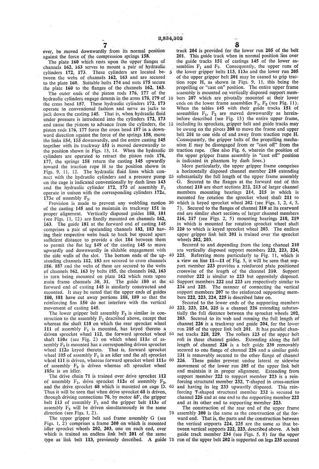
15 United States Patent Office 2,834,302 Patented May 13, ,834,302 s SELF-PROPELLING AERIAL TRAMWAY CAR Leroy, Nixon, Newtown, Pa. assignor to John A. Roeb ling's Sons Corporation, Trenton, N. J., a corporation of Delaware Application April 30, 1954, Serial No. 426, Claims. (Cl ) This invention relates to aerial tramways and more particularly to Systems which utilize ropes as trackways upon which a suspended tramway car travels. Still more particularly the invention relates to self-propelled aerial tramway cars in which a prime mover is carried on the car itself to drive the car along the rope trackway. In Some aerial tramway systems the rope, suspended or otherwise mounted on suitable spaced towers or other mounting devices, is caused to move by a system of rotated sheaves and the cars or carriers are in one way or another, secured to the moving rope, usually steel wire rope, and thus transported with the rope along the path of travel of the rope. In others, the wire ropes are stationary; that is, they do not move in the direction of the path of the rope but the ropes serve as trackways on which wheels of trolleys roll, the car being suspended from the trolleys; and, the stationary rope track serves to carry the weight of the suspended car and such addi tional lading or load, such as freight and the like, as may be placed upon the car for transportation. In the sta tionary rope track systems wherein the aerial tramway car is equipped with wheels or other rolling members which roll on the stationary rope track, the car may be moved along the rope track by a tow rope secured to the car, which tow rope may be caused to be moved or pulled by some suitable arrangement such as a windlass or by a system of rotated sheaves which normally are installed at way stations along the path of the stationary rope track so that, in effect, the cars are pulled or towed from one place to another along the rope track. Or, in a stationary rope track system the tramway car itself may carry a suitable driving mechanism to cause the wheels of the trolley to roll on the rope track. This latter type of car is herein referred to as a "self-propelled aerial tramway car. That is, a prime mover is mounted on the car to drive it along the trackway and it is to this type of aerial tramway system that this invention relates. In accordance with the invention a self-propelled aerial tramway car is provided which has trolleys which ride on and move along a stationary rope track, the car being suspended from the trolleys. The car is equipped with a propelling mechanism which comprises a gripper mecha nism operative to be engaged to and disengaged from a stationary traction rope positioned in the path of travel of the car. The propelling mechanism comprises comple mentary continuous link belts; the links of which carry traveling shoes or treads which are caused to grip the traction rope with sufficient friction to cause the car to move along the rope track as the shoes travel along the stationary traction rope. The traveling shoes engage the traction rope over a considerable length to provide ample driving power to transport the car and its lading. 1. The propelling mechanism is so contrived that it may be readily engaged with the traction rope in operative posi tion (viz.: cast on' to the traction rope) to propel the car or disengaged from or cast off" from the traction rope. This feature is of significant importance because this arrangement provides a convenient way of transfer ring a car from the tail end of one length of rope track to the head end of the next length of rope track in a system which covers a great distance requiring a plurality of suspension towers. This "casting off feature has other advantages mentioned in further detail hereinafter. According to one embodiment of the invention, the aerial tramway car is provided with a trolley or truck at each end of the car and a trolley or truck intermediate the two end trolleys, each trolley or truck being provided with two pairs of oppositely disposed wheels having grooved peripheral flanges which are adapted to ride and roll on a pair of suspended parallel ropes providing a rope track or ropeway on which the trolley wheels roll. Of course, a different number of trolleys may be utilized, if desired. The main frame of the tramway car is sus pended on the trolleys by suitable members secured to the trolley frames and the main frame. Suspended from the main frame is an operator's cage which also provides means upon which to mount a prime mover for driving the car and also to mount other equipment, such as mech anism for lifting and lowering a lading carrier, which may also be suspended from the main frame. The mech anism for engaging the traction rope and propelling the car is mounted on the main frame and is connected to the prime mover through suitable driving connections which may be link chains, gearing, or other suitable driv ing means. The propelling mechanism comprises, in general, an upper frame mounting a sprocket wheel for rotation at each end; an endless or continuous link belt carrying a continuous line of gripper shoes or treads being trained over the two upper frame sprockets and the propelling mechanism includes two lower frames, each of which is provided with a pair of sprocket wheels, one of each pair being driven by the prime mover mounted on the car, an endless link belt carrying a continuous line of gripper shoes or treads being trained over the sprocket wheels. The lower run of the upper continuous link belt and the upper runs of the two lower continuous link belts lie adjacent each other in such manner as to grip a sta tionary traction rope when it is desired to propel the car and the arrangement is such that the traction rope grippers may be caused to grip the traction rope to propel the car or to be disengaged and cast off from the traction rope to release the car from the traction rope. Although the novel features which are believed to be characteristic of the invention will be pointed out in the annexed claims, the invention itself as to its objects and advantages and the manner in which it may be carried out may be better understood from the following description taken in connection with the accompanying drawings forming a part hereof, in which: Fig. 1 is a side view in elevation partly broken away of the forward end of an aerial tramway car embodying the invention; Fig. 2 is a side view in elevation partly broken away of the part of the car intermediate the forward and rear ends; Fig. 3 is a side view in elevation of the rear end of the car. It will be noted that Figs. 1, 2 and 3 together when joined on lines I-I and II-II constitute a side view in elevation of the car with certain parts broken away to reveal the mechanism. Figs. 4 and 5 are side views in elevation and when joined on lines III-III represent a side view in elevation partly broken away and to larger scale of the forward end of the car shown in Fig. 1; Fig. 6 is a view on line 6-6 of Fig. 4 showing a trolley and the manner of securing the main frame thereto; it being noted that the lower part of the drawing is to smaller scale because of limitations imposed by the size of the sheet;

16 .??????????????????..??????????????? 3. Fig. 7 is a view on line 7-7 of Fig. 4 showing the gripper belt sprockets at the forward end of the propelling mechanism; Fig. 8 is a view on line 3-8 of Fig. 5 showing a gripper belt sprocket having a drive pulley on its shaft; Fig. 9 is a view on line 9-9 of Fig. 5 showing par ticularly the gripper belts in operative position engaging the traction rope; Fig. 10 is a view on line of Fig. 9; Fig. 11 is a view on line of Fig. 5 showing the parts in operative position and particularly the manner of mounting the upper gripper belt and frame assembly; Fig. 12 is a side view in elevation and partly in section on line of Fig. 11 showing particularly the guide and support for the upper run of a lower gripper belt; Fig. 13 is a view similar to Fig. 11 but showing the parts in inoperative or cast off position; Fig. 14 is a view similar to Fig. 12 but showing the parts in inoperative or cast off position and on line i4-14 of Fig. 13; Fig. 15 is a side view in elevation and partly in section of a length of gripper belt showing typical gripper links; and Fig. 16 is an end view of a typical gripper link; and Fig. 17 is a view in section of a gripper link on line of Fig. 15. Referring now to the drawings (Figs. 1, 2, 3) wherein there is illustrated an aerial tramway car embodying the invention, the car, in general, comprises a plurality of trolleys A (designated separately by reference numerals A, 1, 2, 3) having wheels all adapted to roll on a rope track B, a main frame C suspended from the trolleys and on which is suspended an operator's cage D upon which may be mounted a prime mover to operate the propelling mechanism E. The propelling mechanism E. comprises, in general, two lower gripper frame assemblies F and F. and an upper gripper frame assembly G. The two lower assemblies F1 and F2 are mounted on main frame C and each includes an endless traveling gripper link tread belt, the upper run of which is supported on guides normally urged upwardly to cause the treads of the upper run to engage a stationary traction rope H. The upper assembly G includes an endless traveling gripper link tread belt, the lower run of which travels along a guide above the upper runs of the traveling endless belt on the lower assemblies F1 and F2 and the treads engage the stationary traction rope H. The rope H is gripped be tween the lower run of the upper belt and the upper runs of the lower belts with sufficient friction to cause the car to be transported along the rope track B when the belts are caused to travel. The upper frame assembly G, in cluding its frame members, guides, sprocket wheels, and link gripper belt, is carried on the lower frame assemblies Fi and F2 which in turn are carried on main frame C. The assemblies F, F, and G of the propelling mechanism : are so arranged and mounted that they may be manipu lated to move the gripper belts to a position in which they are disengaged from the traction rope H and thereby to release the traction rope from the grip of the upper and lower belts and thus to permit the propelling mechanism E to be "cast off" from the traction rope; or, the propelling mechanism E may be manipulated to bring the gripper belts into operative position in which they engage the traction rope with sufficient friction to drive the car in either direction along the rope track B. A suitable lading carrier (not shown) may be suspended from the rear portion of the main frame C and, if desired, it may be in the form of an elevator carrier which may be lifted and lowered by suitable mechanism which may be mounted on and operated from a prime mover carried on the operator's cage D. In the illustrative embodiment shown in the drawings, in which like reference characters denote similar parts, a typical trolley A is perhaps best illustrated in Fig. 6 taken with Fig. 1 where it is shown on the rope track 5 O B which comprises two parallel stationary steel wire ropes 10 and 11. It will be understood that the wire ropes 10 and 11 are suspended overhead by mounting them at both ends on suitable towers or other mounting means placed a considerable distance apart. As shown, each trolley has two pairs of oppositely dis posed wheels 12, 13, and 14, 15, each wheel being mounted on a stub shaft 16 (see Figs. 1 and 6). The stub shafts are mounted on horizontal frame members 18, 19 secured to vertical frame members 20, 21. The wheels, having an annular grooved tread surface 17, are mounted for rota tion and roll on the stationary ropes 10 and 11 which form the trackway. The lower ends of vertical frame members 20, 21 are secured to the outer ends of two out Wardly extending arm members 22, 23 by bolts 24, 25. The inner ends of the arms are secured to a centrally lo cated vertically disposed frame member 26 by a bolt 27, which passes through a clevis 28 secured to main frame C by bolt 29. The main frame C of the car comprises, in general, a pair of horizontal oppositely disposed channel members 30, 35 extending the full length of the car and having their webs 32, 33, positioned and maintained in vertical planes in spaced parallel relation by structural members placed at various places along the length of the two main channel members 30, 31, these structural members being referred to in further detail hereinafter. One such structural mem ber is an inverted channel 34 which extends from a point slightly forward of the clevis 28 of the forward trolley A, 1 and slightly aft of the clevis 28 of the intermediate trolley A, 2 to provide ample strength where the propelling mechanism E is located. Referring to Fig. 6, it will be noted that the lower flanges 36, 37 of the main channels 30, 31 rest on and are secured to the web 35 of the chan nel 34. The rear end portion of the main frame C aft of the operator's cage D provides means upon which to Suspend a lading carrier (not shown) which may be, if desired, of a type suspended on suitable ropes and lifted and lowered by suitable mechanism. Such mechanism may, if desired, be mounted on the cage D. Thus, the main frame C provides means upon which to mount the propelling mechanism E, which includes upper assembly G and lower driven assemblies F and F, and traction rope guide sheaves 270, 271, fore and aft, respectively. It will be observed also that bracing members 39, 40, 41, Secured to the frames of trolleys A, 1, 2, 3, and anchored to structural members secured to the main frame C, are provided on each side of the main frame to provide addi tional strength and desired rigidity. The cage D comprises structural steel members secured together to form a means for mounting a prime mover and such other equipment as may be desired for operat ing the car and its various mechanical devices. As shown, it comprises a plurality of channels 45, 46, 47, 43 secured together to form a rigid suspended platform base or floor 49. Vertical angle members 50 on each side of the base and at its corners are secured to the base at their lower ends. The upper ends of these ver tical angle members are secured to a rectangular frame 5 comprising suitable brace channel members 52 and angle members 53. The cage is suitably braced by cross brace members 54, 55, 56, 57, 58 to give strength and desired rigidity. The cage D is suspended from main frane C in any suitable manner. As shown, cross angle member 60 secured to the main frame supports a plate 62 which in turn is secured to cross channel 52, there being a similar cross angle 60 and plate 61 on each of the cross channels 52 of the upper frame 5 of the cage D. The cage is further secured to the main frame C by vertical plates 62 secured to the webs of channel 34 which plates are in turn secured to a cross channel member 63 which is Secured to angle members 53 of the upper rectangular frame 51 of the cage, A prime mover and such other equipment as may be

17 5 necessary to drive the car and operate the various me chanical devices on the car may be mounted and car ried on the cage D. In the embodiment illustrated in the drawings, an internal combustion engine 65 is mounted on channels 66 extending crosswise of the frame members 45, 46, 47, 48. The drive shaft 67 of the motor 65 is connected with a driving sprocket wheel 68 mounted on the cage for rotation. The driving con nections are indicated conventionally in dash lines. The sprocket wheel 69 is driven by motor 65 and it drives sprocket wheel 68 through a transmission, clutch, and chain drive mechanism, designated generally by refer ence numeral 70. It will be understood that the drive mechanism from the motor 65 may take various forms to rotate the drive sprocket wheel 68, which, as shown, is mounted on the cage for rotation. Trained over the driving sprocket wheel 68 is a link chain belt 71 which is trained over drive sprockets on the gripper assem blies as described in further detail hereinafter. The propelling mechanism, which is mounted and car ried on the main frame C, comprises, in general, an upper gripper belt assembly G, having an endless gripper link tread belt which is not driven and two lower gripper belt assemblies F and F2, each of which is driven by motor 65 mounted on cage D, as described hereinafter. That is, the upper gripper belt is trained over idler, freely rotating sprocket wheels whereas each of the two lower gripper belts is trained over sprocket wheels at least one of which is power driven. Inasmuch as the two lower assemblies F, F2 are sub stantially alike, it will suffice to describe only one in detail. Mounted on the main channels 30, 31 are two upstanding plates 100, 01 (see Figs. 4, 7) which carry bearings 102, 103 in which are mounted for rotation a sprocket shaft 104 to which is keyed an idler sprocket wheel 05; and also two upstanding plates 106, 107 (see Figs. 5, 8) which carry bearings 108, 109, in which are mounted for rotation a sprocket shaft 110 to which is keyed a driven sprocket wheel 111. It will be noted that shaft 110 has keyed thereto at its outer end a drive sprocket wheel 12 over which is trained the sprocket drive chain 71 previously referred to. Trained over idler sprocket wheel 105 and driven sprocket wheel 111 is an endless link belt 13, each link of which includes a tread shoe housing in which is mounted a tread shoe of resilient material, which may be rubber, synthetic elastomer, or other suitable material having resilient and wear resisting characteristics. This type of belt is herein referred to as a gripper belt. The links them selves which make up the endless gripper belts, like gripper belt 113, are perhaps best shown in Figs A belt comprises a number of links, the alternate ones of which are alike. A typical link 118 comprises side link plates 120, 121 having bores 122 through which extend pins 119 on which rollers 23 are mounted for rotation; the rollers 123 being spaced apart by spacers 124, The side plates 120, 21 are turned outwardly at right angle to form plate supporting portions 126, 127 for attaching a shoe housing 125. The flat portions 126, 127 have bores 128 registering with bores in cross plate 129 to which the shoe housing 125 is secured by bolts 130. It will be noted that the links are alike except that the side link plates 120a, 121a of alternate links are slightly different in that the portions 126a, 127a are narrower than the corresponding portions 126, 127 of the next adjacent link so that when the side plates 120, 121 of the link are mounted on the pins 119, the side plates of the link on each side of it are behind the corresponding side plates 120a, 121a. The shoe housing or retainer 125 is of particular shape to retain the resilient gripper shoe 131 which, as shown, is wear resisting synthetic elastomer. The shoe retainer casting 125 comprises a flat portion 132 from which extend outwardly directed side walls 134, 135 and end 2,834, walls 136, 137 and reinforcing ribs 138. The inner surfaces of the side walls 134, 135 taper so that the cor respondingly shaped outer strface of the resilient shoe 131 is securely maintained in place in the retainer cup 140, formed by the retainer casting 25. The shoe 131. has a centrally, located longitudinal groove 41 to con form with the outer peripheral surface of the traction rope H and the shoe extends a little beyond the edges 142 of the retainer cup 540 (see Fig. 17). It will now be seen that the traction rope can be gripped between the resilient shoe of a link below the rope and the resilient shoe of the link above the rope when the links above and below the rope are urged toward each other into engagement with the rope. Referring again more particularly to the lower grip per assembly F1, there is provided a gripper belt guide and support member which preferably is in the form of a casting 45. This guide and support member 45 is positioned between sprockets 105, 411 and between the upper run 146 and the lower run 47 of the endless link belt 13. This casting 145, which is T-shaped in cross section, comprises a table portion 48 of considerable: length from which depends a centrally located plate or leg portion 149 and reinforcing fins 150 (see particularly Figs. 4, 9, 11, 12). The table 148 provides means on: which is securely supported a trackway 151 on which the rollers 123 of the links of the upper run 146 of belt 13 may roll. It will be noted that the trackway 151 is provided with guide channels 152 to receive and guide the rollers 23. The casting 145 is so arranged. that it may be moved upwardly and downwardly within limits and it supports and guides the upper run 46 of the gripper belt 113. It is normally urged upwardly by springs, later to be described, and in normal position urges the tread shoes 131 of the links of the upper run 146 of the belt 1:3 toward the lower run of a similar link belt which is supported by and travels freely on sprockets mounted on the upper gripper frame assembly G, described in further detail hereinafter. The supporting casting 145 (see Figs. 9, 10, 11, 12) has a horizontal bore located below the table portion 148 and midway of its length, through which a pin 153 ex tends. Pivotally mounted on the pin 153 on each side of the plate or leg 149 is a link 154, i55, the other ends of each of these links being pivotally mounted on pin 156 which extends through a bore midway of a cross head 157. However, the casting 145 is supported on compression springs 158 which are in turn supported on suitable mem bers which are mounted on and carried by the channels 30, 31 of the main frame C (see Figs. 4, 5, 9). A row of compression springs 58 is provided under the table portion 148 along each side of the leg 49. The lower ends of springs 158 rest upon a base plate 60 which in turn rests upon a pair of channel members 62, 163, main tained in parallel spaced relation; it being noted that the lower flanges of these channels rest upon a plate 64 which rests upon the upper flanges of main frarine channels 30, 31. The plate 263 has a cut out porticin i34 and the plate 61 has a cut out portion i65 through which the links 54, 155 may be moved upwardly and downwardly. The manner of mounting the compression springs 158 is shown perhaps best in Fig. 9 wherein a typical mount ing will be seen for each spring 153. A long bolt i66 extends through a bore in the table i48 of the casting i45 and through the plate 171 and the flanges 167, 168 of the channel 162. Bolt 166 is maintained in position by suitable nuts 169 on each end of the bolt; a spring retaining sleeve 170 being inserted on the bolt between the plate 17 which rests upon the flanges 162, 63, and the table portion 148 of casting 45. Each of the springs 158, in the rows of springs extending along the fiat legs. 149 of the casting 145, is similarly mounted. Although the springs 158 normally urge the casting 45 and its table 148 and its trackway 151 upwardly, it may, how
18

19 2,834, to the channel 210. This prevents undue sag in the up per run of the upper gripper belt. The manner of pivotally mounting the upper frame as sembly G to the lower frame assemblies F, F may be understood by particular reference to Figs. 4, 5, 11, 12, 13, 14. There are four vertically disposed tubular post members 207 which support the upper frame assembly G on the lower frame assemblies F, F2. One pair is pivoted to the assembly F and the other pair to assembly F2; both pairs being mounted in the same way. Referring 0. to Fig. 11, showing a view of a typical mounting, it will be seen that the tubular support post 207 has at its upper end an outwardly extending flat rigid cantilever arm 240, secured to the reinforced plate 223 by bolts 24 and at its lower end a flat rigid lever arm 242, ex tending outwardly in the same plane as arm 240. The arm 242 is further reinforced with a narrow plate 243. The lever arm 242 has a bore through which extends pivot pin 208 which is mounted in registering bores in up standing side plates 244, 245 of a clevis mounting mem ber 246. Flanges 248, 249 at the lower end of the clevis member 246 are secured to the webs of main frame channels 30, 31 (see Figs. 11, 12). The outer end 250 of arm 242 extends beyond the plane of the web of main channel 30 and engages mecha nism which is operative to maintain the outer end of arm 242 in down position and thereby maintain the upper frame assembly 200 in operative position (as shown in Fig. 11) or to raise the outer end of arm 242 to up posi tion, thereby tilting the arm to rotate it about pivot 208 to swing the assembly away from the traction rope H to inoperative position (as shown in Fig. 13). The arm tilting mechanism just mentioned comprises a crossarm member 251 positioned above and engaging the outer end portion 250 of arm 242 (see Figs. 5, 11). The crossarm is movable vertically within limits and is normally urged downwardly against lever arm 242 by compression springs 252, 253 mounted on telescoping sleeve spring retainers 254, 255 which are mounted on the long bolts 256, 257. These bolts, one at each side of arm 242, extend through bores in crossarm 25i; through bores in a bracket plate 258; and then through bores in the flanges of two angles 259, 260 which are secured to the web of main channel 30. Bracket plate 253 rests on and is secured to the upper flange of channel 35. Bolts 256, 257 are maintained in place and prevented from vertical movement by nuts 261, above and below the angle iron flanges 259, 260. Nuts 262 at the upper ends of the bolts provide stops for restraining upward move ment of spring retainers 254, 255. A vertically disposed hydraulic cylinder 263, mounted between bolts 256, 257, rests upon the flanges of angles 259, 260 and extends through a cut out portion in bracket plate 258. The outer end of piston rod 264 of the hy draulic cylinder engages the underside of the outer end portion of arm 242. Normally the piston rod is in re tracted position (as shown in Fig. 11) by reason of the force exerted downwardly on cross-arm 251 by com pression springs 252, 253, which springs maintain upper frame assembly 200 in operative position when piston rod 264 is in retracted position. The hydraulic cylinder is operated in conventional fashion and serves as a jack to jack up the lever arm 242. That is, when hydraulic fluid under pressure is introduced into the cylinder, piston rod 264 is advanced and raises the outer end of arm 242 against the force of springs 252, 253 and rotates the arm about pivot 208, to swing the upper frame assembly 260 to the position shown in Fig. 13. When piston 264 is retracted, compression springs 252,253 force crossarin 251 downwardly and this rotates the arm 242 and hence upper assembly 200 back to normal position, as shown in Fig. 11. Adjustable stops 265, 266 are provided to limit the rotational movement of arm 242 about its pivot 283. There are four supporting posts 207 and each has an operating mechanism like the one just described; it being O noted that there are a pair mounted on assembly F1, one of the pair at its fore and the other at its aft end and a similar pair mounted on assembly F. All four hy draulic cylinders 263 operate in unison through the hy draulic system indicated conventionally by dash lines 144. A traction rope guide sheave 27 at the fore end of the main frame C and a similar sheave 271 at the aft end of the main frame are mounted for free rotation on up standing plates 272, one on each side of the sheave, and secured to the main frame. These guide sheaves have grooved peripheral flanges and serve to guide the sta tionary traction rope H as the car is propelled in either direction along the path of the rope. The aerial tramway car described above may be oper ated as follows: Assume that the car is in operative posi tion; that is, the trolleys A are suspended on the ropeway B and the propelling mechanism is in operative position, '(viz.: cast on' to the traction rope). In this position the traction rope H is gripped by the gripper shoes 13 of the lower run 205 of the upper gripper belt 201 which is trained over sprocket wheels 202, 203 of the upper as sembly G and by the gripper shoes 31 of the upper runs 146 of the lower gripper belts 13, 113a, which is trained over sprocket wheels 105, it and 165a, 11a of the lower gripper assemblies F, F2. The motor 65 drives sprocket 68 through the driving connections 79 which are provided with transmission to drive sprocket 68 in either direction. Assuming sprocket 68 is rotated in clockwise direction, as viewed in Figs. 1, 2, drive chain 71 drives sprockets 112, 2a in the same direction, causing gripper belts 3, 15.3a to travel in a clockwise direction; that is, the upper runs 46, 146a of these belts travel from left to right relatively to main frame C, as viewed in Figs. 1, 2. Inasmuch as compression springs 158 urge casting 145 upwardly, the gripper links rolling on supporting trackway 151 are urged upwardly into engagement with stationary traction rope Hsince the guide trackway 204 of the upper assembly G is in fixed position relatively to the main frame and the rollers of the links of the lower run 205 of the upper gripper belt roll along trackway 204 and consequently the gripper shoes i3 of these links, in effect, exert a force in a downward direction opposite to the upwardly exerted force of the springs 58. Hence the traction rope is gripped between the lower run of the upper gripper belt and the upper runs of the lower gripper belts over a substantial distance around the rope and also along tractoin rope H. That is, there are a plurality of tread surfaces engaging the traction rope over a wide area both laterally and longitudinally of the rope. As the upper runs of the driven lower gripper belts move from left to right relatively to the main frame C and along the path of traction rope H (as viewed in Figs. 1, 2, 3), the lower run of the upper gripper belt moves along at the same speed because the upper belt is an idler belt since the sprockets 202, 203 are mounted for free rotation. Since the traction rope is stationary, that is, it does not move in a direction along the path of travel of the car, the car itself is propelled along the traction rope in a direction from right to left (as viewed in Figs. 1, 2, 3). The relation of various parts of the propelling mechanism when it is in operating position is illustrated in Figs. 9, 11, 12. Of course, the car may be driven in the op posite direction by reversing the direction of travel of the gripper belts. Assume now that it is desired to disengage the gripper belts from the traction rope, that is, to move the pro pelling mechanism to inoperative position. The provision for disengaging the grippers from the traction rope in such manner that the car may be cast off from the traction rope is of important significance because it permits of readily and easily transferring the car from the tail end of a section of overhead ropeway to the head end of an adjoining section of overhead ropeway, for example, where said tail end and head end are secured to a high tower, as they must be in a long distance overhead tram

20 2,834, way where many towers may be required. Of course, it of the lower run of said upper belt being complementary will be manifest to those skilled in the art that this to and mating with the grippers of the upper run of said "cast off feature has other advantages. lower belt, said mating grippers being engageable with and The relation of various parts of the propelling mech disengageable from said traction rope, levers pivotally anism in inoperative or "cast off" position is illustrated 5 mounted on said lower frame, the pivotal axis of said levers in Figs. 13, 14. To bring the propelling mechanism to lying in the plane of said sprockets and directly beneath cast off position, the piston rods of hydraulic cylinders and parallel with said rope when said rope is gripped be 172, 73 located beneath the castings 45 in both lower tween said mating grippers of the upper and lower runs assemblies F, F2 are caused to be advanced by intro of said belts and said levers mounting said upper frame ducing hydraulic fluid into the cylinders through lines O for swinging movement about said pivotal axis, a power i43 (see Figs. 1, 2). This forces the crossheads 157 driven mechanism connected to drive at least one of said downwardly and moves the castings 145 of assemblies belts, an upper trackway guide above the lower run of F1, F2 downwardly against the upwardly exerted force said upper belt, a lower trackway guide below the upper of springs 158, to free traction rope H from the grip of run of said lower belt, yieldable means normally urging the upper and lower gripper belts. After the castitngs 45 the grippers of the upper run of said lower belt and the and their trackways i5 (of both assemblies F1, F) are lower run of said upper belt into gripping contact with forced down by the hydraulic cylinders 72, 173, then said traction rope, said grippers driving said device along hydraulic fiuid under pressure is introduced simultaneous said traction rope when the mating grippers of said belts ly into the four hydraulic cylinders 263 to advance piston are in gripping contact with said traction rope and said rods 264 of these cylinders. This raises the outer ends 20 pelts are driven by said driving mechanism, jack means of the pivoted lever arms 242 against the forces of springs on said device connected to said lower trackway guide operative to overcome the force of said yieldable means which normally urge said mating grippers into gripping contact to disengage the mating grippers from gripping contact with said traction rope and to separate said mat ing grippers, and other mechanically operated means on said lower frame engaging said levers to rotate said levers about said pivotal axis to swing said upper frame to move 252, 253 and rotates the four arms 242 about their pivots 208. This, in turn, swings the upper frame as sembly including sprockets 202, 293, upper gripper belt 201, and its trackways and guides, in an arc away from traction rope H (as illustrated, for example, in phantom by dash lines 269 in Fig. 6), so that the propelling mech anism of the car itself is cast off free from the traction rope. The manner of reengaging the propelling mechanism to the traction rope will be understood from the fore going. Suffice it to say that the piston rods 264 of the four hydraulic cylinders 263 are retracted to permit springs 252, 253 to return the arms 242 to normal posi tion, to swing the upper frame assembly 260 over the traction rope and the castings 145 of assemblies F, F, are raised by retracting the piston rods 176 and 77 of hydraulic cylinders 72, 73, and the springs 158 urge the castings upwardly so that the gripper belts grip the traction rope as illustrated in Figs. 9, 11. It will be seen from the foregoing that the propelling mechanism provides an upper traveling endless gripper belt 201 which is complementary to the lower gripper belts 113, 13a and each of these belts carry traveling gripper links 118; the gripper links of the upper belt being com plementary to the gripper links of the lower belts and each link of each oppositely disposed pair of links has a traction rope engaging surface, as shown, for example, in Fig. 9, and the traction rope is gripped between each complementary pair as they move along the path of the rope H. The springs 158 exert an upward force on cast ings 145 and hence on the gripper links, thus each comple mentary pair of links is urged toward each other to bring the rope engaging surfaces of the links into gripping en gagement with the traction rope and the cylinders 176, 177 and 263 provide means operative to move the comple mentary gripper links away from each other to release them from gripping engagement with the rope to free it so that the car may be cast off or freed from the traction rope. The terms and expressions which have been employed herein are used as terms of description and not of limita tion, and there is not intention in the use of such terms and expressions of excluding any equivalent of the fea tures shown and described or portions thereof, but it is recognized that various modifications are possible within the scope of invention claimed. What is claimed is: 1. A power driven propelling device for hauling on a stationary traction rope comprising an upper and at least one lower frame, a lower endless travelling link belt mounted on sprockets on said lower frame, an upper end less travelling link belt mounted on sprockets on said up per frame, said sprockets normally lying in a single plane, said belts carrying traction rope grippers, the grippers the grippers of said upper belt free from said traction rope, when said mating grippers are in separated position. 2. A power driven propelling device for moving an aerial tramway car along a suspended overhead stationary traction rope comprising an upper and two lower frames, a lower endless travelling link belt mounted on sprockets on each of said lower frames, an upper endless travelling link belt mounted on sprockets on said upper frame, said sprockets normally lying in a single vertical plane, said belts carrying traction rope grippers, the grippers of the lower run of said upper belt being complementary to and mating with the grippers of the upper runs of said lower beits, said mating grippers being engageable with and dis engageable from said traction rope, levers pivotally mounted on said lower frames, the pivotal axes of said levers lying beneath and parallel with said rope and in said vertical plane, said levers mounting said upper frame for swinging movement about the pivotal axis of said levers, a power driven mechanism connected to drive said belts, an upper trackway guide above the lower run of said upper belt, a lower trackway guide below each of the upper runs of said lower belts, compression springs on said lower frames normally urging said lower guides upwardly to force the grippers of the upper runs of said lower belts into gripping contact with said traction rope, said grippers driving said device along said traction rope when said belts are in gripping contact with said traction rope and driven by said driving mechanism, hydraulically operated jacks connected to said lower trackway guides to move said lower trackway guides downwardly against the force of said springs to disengage the grippers of said upper runs of said lower belts from said traction rope, and hydraulically operated jacks mounted on said lower frames and engaging said levers to rotate said levers about their pivots to swing said upper frame to swing the grippers of said upper belt free from said traction rope. 3. A power driven propelling device for hauling on a stationary traction rope comprising an upper and two lower frames, a lower endless travelling link belt mount ed on sprockets on each of said lower frames, an upper endless travelling link belt mounted on sprockets on Said upper frame, said sprockets normally lying in a single vertical plane, said belts carrying traction rope grippers, the grippers of the lower run of said upper belt being complementary to and mating with the grip pers of the upper runs of said lower belts, said mating grippers of the upper and lower belts being engageable
21 2,834, with and disengageable from said traction rope, levers pivotally mounted on said lower frame, the pivotal axis of said levers lying in said vertical plane and beneath and parallel with said rope when said rope is gripped between said mating grippers of the upper runs of said 5 lower belts and lower run of said upper belt, said levers mounting said upper frame for swinging movement about said pivotal axis, a power driven mechanism connected to drive said lower belts, an upper trackway guide above the lower run of said upper belt, a lower trackway guide O below the upper run of each of said lower belts, yield able means on said lower frame normally urging the grippers of the upper runs of said lower belts upwardly toward the lower run of said upper belt to bring the grippers of the upper runs of said lower belts and the 15 grippers of the lower run of said upper belt into grip ping contact with said traction rope, said grippers driv ing said device along said traction rope when the mating grippers of said belts are in gripping contact with said traction rope and said lower belts are driven by said 20 driving mechanism, jack means on said lower frame con nected to said lower trackway guides to overcome the force of said yieldable means which normally urge said mating grippers into gripping contact to disengage the mating grippers from gripping contact with said traction 25 rope and to separate said mating grippers, and other mechanically operated means on said lower frame en gaging said levers to rotate said levers about said pivotal axis to Swing said upper frame to move the grippers of said upper belt free from said traction rope, whe said mating grippers are in separated postion. 4. A power driven propelling device constructed ac cording to claim 1 in which said yieldable means nor mally urging said grippers of the upper run of the lower belt comprises an elongate member which is T shaped in cross section and compression springs mount ed on the lower frame assembly urging said T-shaped member upwardly against the upper run of said lower belt. 5. A power driven propelling device constructed ac cording to claim 4 in which said jack means on said lower frame which are connected to said trackway guides to overcome the force of said compression springs com prise hydraulic jacks mounted on said lower frame adapted to be operated from a source of hydraulic power remote from said hydraulic jacks. 6. A power driven propelling device constructed ac cording to claim 5 in which said mechanically operated means on said lower frame engaging said levers to rotate said levers about their pivotal axis comprises hydraulic jacks mounted on said lower frame having piston rods having a lifting action on said levers to swing said upper frame to cast-off position in which the upper belt is free from the traction rope A power driven propelling device constructed ac cording to claim 2 in which said lower trackway guides are elongate members having a generally T-shaped cross section and said jacks which engage said levers have piston rods having, on their forward stroke, a lifting action on said levers to Swing said upper frame to cast off position in which said upper belt is free from said traction rope and said hydraulic jacks connected to said trackway guides may be operated from a place remote from said jacks. 8. A power driven propelling device constructed ac cording to claim 7 which also includes a spring biased means on said lower frame engaging said levers urging said upper frame to cast-on position in which the grip pers of the lower run of said upper belt are in contact with said traction rope when said piston rods are re tracted. 9. A power driven propelling device constructed ac cording to claim 3 in which said yieldable means nor mally urging the grippers of the upper runs of the lower belts upwardly comprises compression springs mounted on said lower frame urging said lower trackway guides upwardly against the upper runs of said lower belts and said jack means for overcoming the force of said compression springs are hydraulic jacks operable from a place remote from said jacks and said other mechanical ly operated means engaging said levers to rotate said levers comprises hydraulic jacks having piston rods to exert a lifting action on said levers on their forward stroke and controlled from a place remote from said last mentioned jacks A propelling device constructed according to claim 9 in which the means for swinging said levers about their pivots include spring biased means urging said levers to move said upper frame to cast-on position in which the grippers of the lower run of said upper belt en gages said traction rope, when said piston rods are in retracted position. References Cited in the file of this patent UNITED STATES PATENTS 1,313,358 Watkins Aug. 19, ,321,463 Lloyd Nov. 11, ,527,489 Pendleton Feb. 24, ,018,087 PlaSS Oct. 22, ,038,732 Guthrie Apr. 28, ,349,263 Grabinski May 23, ,547,935 Grabinski Apr. 10, 1951 FOREIGN PATENTS 117,541 Austria Apr. 25, ,559 Austria Apr. 25, ,063 Great Britain June of 1885
"(2.4% May 4, 1954 C. A. GUSTAFSON 2,677,202. Filed April 3, l95l AND EJECTOR OF EARTH-MOWING SCRAPERS 3. Sheets-Sheet CAR. A.
 May 4, 1954 C. A. GUSTAFSON 2,677,202 HYDRAULIC ACTUATOR FOR OPERATING THE APRON Filed April 3, l95l AND EJECTOR OF EARTH-MOWING SCRAPERS 3. Sheets-Sheet INVENTOR, CAR. A. G2/S7AASOM/ "(2.4%. 2.-- ATTORME,
April 3, 1956 J. MONTANA 2,740,484 MOTOR DRIVEN STAIR CLIMBING HAND TRUCK
 April 3, 1956 J. MONTANA 2,740,484 MOTOR DRIVEN STAIR CLIMBING HAND TRUCK Filed Aug. 26, 1950 3. Sheets-Sheet l //WVEW7OA JAMES MOW/AWA April 3, 1956 J. MONTANA 2,740,484 MOTOR DRIVEN STAIR CLIMBING HAND
Feb. 14, 1967 R. B. WENGER 3,304,094 CLIMBING WHEEL CHAIR A/C. Z. 5 is INVENTOR. a/caezo as a 7/gate, 57 d. 2. XO aoz. 1277aatavays.
 Feb. 14, 1967 R. B. WENGER CLIMBING WHEEL CHAIR Filed Dec. 22, 1964 3. Sheets-Sheet A/C. Z. is INVENTOR. a/caezo as a 7/gate, BY 7 d. 2. XO-4-2. 32427 aoz 1277aatavays. Feb. 14, 1967 R. B. WENGER CLIMBING
(12) Patent Application Publication (10) Pub. No.: US 2006/ A1
 Patent Application Publication (10) Pub. No.: US 2006/ A1") US 20060066075A1 (19) United States (12) Patent Application Publication (10) Pub. No.: US 2006/0066075A1 Zlotkowski (43) Pub. Date: Mar. 30, 2006 (54) TOWING TRAILER FOR TWO OR THREE Publication Classification
US 20060066075A1 (19) United States (12) Patent Application Publication (10) Pub. No.: US 2006/0066075A1 Zlotkowski (43) Pub. Date: Mar. 30, 2006 (54) TOWING TRAILER FOR TWO OR THREE Publication Classification
United States Patent (19) Cronk et al.
 Cronk et al.") United States Patent (19) Cronk et al. (S4) LANDING GEAR FOR ULTRALIGHT AIRCRAFT 76) Inventors: David Cronk, 1069 Eucalyptus Ave., Vista, Calif. 92025; Lyle M. Byrum, 1471 Calle Redonda, Escondido, Calif.
United States Patent (19) Cronk et al. (S4) LANDING GEAR FOR ULTRALIGHT AIRCRAFT 76) Inventors: David Cronk, 1069 Eucalyptus Ave., Vista, Calif. 92025; Lyle M. Byrum, 1471 Calle Redonda, Escondido, Calif.
March 16, ,173,402 W. D. CASSEL AUTOMATIC CATTLE SPRAYER. Filed Aug. 26, Sheets-Sheet l /WA70? WALTER D, CASSEL.
 March 16, 1965 Filed Aug. 26, 1963 W. D. CASSEL 3. Sheets-Sheet l /WA70? WALTER D, CASSEL a 4-4 12, A7/0PAY March 16, 1965 W. D. CASSEL Filed Aug. 26, 1963 3. Sheets-Sheet 2 CN March 16, 1965 W. D. CASSEL
Feb. 9, ,168,853 R. PRINCE HYDRAULIC CYLINEDER DEVICE. Filed Oct. 8, Sheets-Sheet l ~~~~ INVENTOR. 162/12e2 aga/2.
 Feb. 9, 1965 Filed Oct. 8, 1962 R. PRINCE HYDRAULIC CYLINEDER DEVICE 3,168,853 2 Sheets-Sheet l ~~~~ INVENTOR. 162/12e2 aga/2. BY Feb. 9, 1965 R. PRINCE 3,168,853 HYDRAULIC CYLINDER DEVICE Filed Oct. 8,
United States Patent (19)
") United States Patent (19) Ogasawara et al. (54) 75 RDING LAWN MOWER Inventors: Hiroyuki Ogasawara; Nobuyuki Yamashita; Akira Minoura, all of Osaka, Japan Assignee: Kubota Corporation, Osaka, Japan Appl.
United States Patent (19) Ogasawara et al. (54) 75 RDING LAWN MOWER Inventors: Hiroyuki Ogasawara; Nobuyuki Yamashita; Akira Minoura, all of Osaka, Japan Assignee: Kubota Corporation, Osaka, Japan Appl.
W. Hope. 15 Claims, 5 Drawing Figs. (52) U.S. Cl , 5ll int. Cl... F16k 43100, F16k 5/14
 U.S. Cl , 5ll int. Cl... F16k 43100, F16k 5/14") United States Patent (72 inventor Clyde H. Chronister 4 Kings Row, Rte. 14, Houston, Tex. 77040 (2) Appl. No. 823,103 (22 Filed May 8, 1969 45 Patented Jan. 26, 197i. 54) GATE WALVE 15 Claims, 5 Drawing
United States Patent (72 inventor Clyde H. Chronister 4 Kings Row, Rte. 14, Houston, Tex. 77040 (2) Appl. No. 823,103 (22 Filed May 8, 1969 45 Patented Jan. 26, 197i. 54) GATE WALVE 15 Claims, 5 Drawing
Az Z 1.357,665. Azzee/2Z27. Patented Nov. 2, y 24-cee?, A-6. vy
 1.7,665. P. H. WATKNS, (UM SHEETING AND SCORING MACHINE, APPLICATION FILED MAY 28, 1920. Patented Nov. 2, 1920. 2 SHEETS-SHEET 1. Az Z B Azzee/2Z27 A 27/62//l/2éAz72s. y 24-cee?, A-6. vy-4----. P, H, WAT
Aug. 10, ,595,232 W. S. HARLEY ELECTRIC SWITCH. HParié a. % - se. Zezezza77. Za2z/2a22 J/622ce/ 72/ ( clo-c-3 v (J.,
 Aug. 10, 1926. 1,595,232 W. S. HARLEY ELECTRIC SWITCH Filed April 13, 1922 2. Sheets-Sheet f t Fre ls HParié a % - se Sh Zezezza77 Za2z/2a22 J/622ce/ 72/ ( clo-c-3 v (J., Aug. 10, 1926. 1,595,232 W. S.
United States Patent (19) Miller, Sr.
 Miller, Sr.") United States Patent (19) Miller, Sr. 11 Patent Number: 5,056,448 (45) Date of Patent: Oct. 15, 1991 (54) (76. (21) (22) 51 (52) (58) PVC BOAT Inventor: Terry L. Miller, Sr., P.O. Box 162, Afton, Okla.
United States Patent (19) Miller, Sr. 11 Patent Number: 5,056,448 (45) Date of Patent: Oct. 15, 1991 (54) (76. (21) (22) 51 (52) (58) PVC BOAT Inventor: Terry L. Miller, Sr., P.O. Box 162, Afton, Okla.
s l N 2. S Aoaaaz A. u?acasow M-74a/oway, Alaata(7 & March 30, 1965 R. E. JACKSON 3,175,811 INVENTOR. A/Oaavaaaata
 Filed April 23, 1963 4. Sheets-Sheet l. N N 2. s l s los & N " S S Aoaaaz A. u?acasow s M-74a/oway, Alaata(7 & A/Oaavaaaata 477aaAVay13. Filed April 23, 1963 4. Sheets-Sheet 2 Aroaaaz at 14 ca?sow M14A/o/ay,
Dec. 3, G. H. LELAND 1,737,595 ELECTRIC MOTOR W/a Av/2Ap. 2-2, 3 3 6AOAGAA. l. E/A/VD. 4772A/VAy
 Dec. 3, 1929. G. H. LELAND 1,737,595 ELECTRIC MOTOR. Filed Sept. 20, 1926 2 Sheets-Sheet - - - - - - 9. -- W/a Av/2Ap. 3 3 6AOAGAA. l. E/A/VD. 2-2, 4772A/VAy Dec. 3, 1929. G. H. LELAND 1,737,595 ELECTRIC
?zzzzzzzzzzzzzzzzzzzzzzzzzzzzzzzzzzzzzzz -! zzzzzzzzz,zzzzzzzzz. sssss?sssssss,! PATENTED JULY 21, PNEU MATIC SUSPENSION MEANS, J. H.
 J. H. CLARK, PNEU MATIC SUSPENSION MEANS, APPLICATION FILED JUNE 24 1907. PATENTED JULY 21, 1908. sssss?sssssss,! S?zzzzzzzzzzzzzZZZZZZZZZZZZZZZZZZZZZZZZZZ -! SN 22 222 zzzzzzzzz,zzzzzzzzz INVENTOR ZVetezrzes...
June 6, ,987,128 W. KREG SOIL, DAMMING IMPLEMENT. Filed June ll, Sheets-Sheet. Werner Arieg INVENTOR. &&. ~~~~
 June 6, 1961 Filed June ll, 197 W. KREG SOIL, DAMMING IMPLEMENT 2 Sheets-Sheet ~~~~ Werner Arieg INVENTOR. &&. June 6, 1961 Filed June ill, 197 W. KREG SOIL, DAMMING IMPLEMENT 2 Sheets-Sheet 2 Werner Arieg
Oct. 8, 1968 F. MELLON 3,404,927 BATTERY DISPENSER. Filed April 17, Sheets-Sheet. 2 CE. 2t c. el-n. e are. Iraverator, 7 e44 %-4-4, t/s.
 Oct. 8, 1968 F. MELLON 3,4,927 BATTERY DISPENSER Filed April 17, 1967 2 Sheets-Sheet. i 3. el-n s e are 2 CE. 2t c 32 N Iran le Iraverator, Mezziorz, 7 e44 %-4-4, t/s. Oct. 8, 1968 Filed April 17, 1967
- F WEN N 42. Czz724,2 Zz-ssa 7ce. E. BY. Oct. 21, 1958 C. F. DASSANCE 2,856,797 3A 42. Filed June 1, 1953 INVENTOR.
 Oct. 21, 1958 C. F. DASSANCE WARIABLE SPEED GEAREO PULEY 2 Sheets-Sheet Filed June 1, 1953 2. WEN N 42 3A 42 INVENTOR. Czz724,2 Zz-ssa 7ce. E. BY - F - 4.2.2 Oct. 21, 1958 C. F. DASSANCE WARIABLE SPEED
3,136,172. June 9, Attorneys C. D. STRANG SHIFT MECHANISM FOR OUTBOARD PROPULSION UNITS. 2 Sheets-Sheet li
 June 9, 1964 C. D. STRANG SHIFT MECHANISM FOR OUTBOARD PROPULSION UNITS 3,136,172 2 Sheets-Sheet li Attorneys June 9, 1964 C. D. STRANG SHIFT MECHANISM FOR OUTEOARD PROPULSION UNITS 3,136,172 Filed March
Nov. 19, 1963 W. J. LEE 3,111,246 SHIRT FOLDING MACHINE Filed May ll, Sheets-Sheet 1 INVENTOR. by A-4,5- anzawy &Arafat
 Nov. 19, 1963 W. J. LEE SHIRT FOLDING MACHINE Filed May ll, 1960 4 Sheets-Sheet 1 Wing A. Lee INVENTOR. by A-4,5- anzawy &Arafat Nov. 19, 1963 W. J. EE SHIRT FOLDING MACHINE Filed May 11, 1960 4. Sheets-Sheet
April 22, 1969 R. R. MYERS 3,439,368 SWIMMING POOL CLEANER. Filled Jan. 3, //V/AA/7OA. aaaaya /7 a.a5. As / Al-Aza 47.4% r-77%---a A77 oawals
 April 22, 1969 R. R. MYERS 3,439,368 Filled Jan. 3, SWIMMING POOL CLEANER //V/AA/7OA aaaaya /7 a.a5 As / Al-Aza 47.4% r-77%---a A77 oawals April 22, 1969 R. R. MYERS 3,439,368 SWIMMING FOOL CLEANER '-
22-y 2 24, 7. -l- az. Z é - Jan. 26, 1971 D. F. webster 3,557,549 TURBOCHARGER SYSTEM FOR INTERNAL COMBUSTION ENGINE. is is a ST.
 Jan. 26, 1971 D. F. webster 3,557,549 23 9 -a- 3. Sheets-Sheet El -l- Area Arena S is is a ST BY DONALD F. WEBSTER Y az. Z 224 724.0 2é - 22-y 2 24, 7 Jan. 26, 1971 D. F. WEBSTER 3,557,549 3 Sheets-Sheet
Jan. 14, ,421,236. Filed June 22, E, U, MOYER ATTORNEYS LINKAGE FOR AN EJECTOR TYPE BUCKET, LOADER
 Jan. 14, 1969 Filed June 22, E, U, MOYER LINKAGE FOR AN EJECTOR TYPE BUCKET, LOADER ATTORNEYS Jan. 14, 1969 E. U. MOYER LINKAGE FOR AN EJECTOR TYPE BUCKET, LOADER Filed June 22, 1967 Sheet a of 2. INVENTOR
(12) Patent Application Publication (10) Pub. No.: US 2008/ A1
 Patent Application Publication (10) Pub. No.: US 2008/ A1") (19) United States US 20080000052A1 (12) Patent Application Publication (10) Pub. No.: US 2008/0000052 A1 Hong et al. (43) Pub. Date: Jan. 3, 2008 (54) REFRIGERATOR (75) Inventors: Dae Jin Hong, Jangseong-gun
(19) United States US 20080000052A1 (12) Patent Application Publication (10) Pub. No.: US 2008/0000052 A1 Hong et al. (43) Pub. Date: Jan. 3, 2008 (54) REFRIGERATOR (75) Inventors: Dae Jin Hong, Jangseong-gun
April 2, 1968 O. BE TRAM 3,375,595 SINGLE BUCKET EXCAVATOR 12 INVENTOR. OS M A NO BE L T R A N. "I'llur awl ov. 4-wa
 April 2, 1968 O. BE TRAM SINGLE BUCKET EXCAVATOR Filed April 27, 1965 2. Sheets-Sheet 12 INVENTOR. OS M A NO BE L T R A N "I'llur awl ov 4-wa April 2, 1968 O. BELTRAM SINGLE EUCKET EXCAVATOR Filed April
809,643. June 9, le A. E. SMALL RAILWAY CAR DROP DOOR
 June 9, 1931. A. E. SMALL RAILWAY CAR DROP DOOR 809,643 Filed April 25, 1929 3 Sheets-Sheet 1 /1 le------------ e. w June 9, 1931. A. E. SMALL Railway, CAR DROP DOOR Filed April 25, 1929 3 Sheets-Sheet
June 25, 1968 ROTH 3,389,738 WINDOW SHADE APPARATUS FG. 2ASE. 4b. NVENTOR LEO ROTH. was 11- a-40, 2.11u1 2y 7. A2-2.1a-42a (arte?. ATTORNEYS.
 June 25, 1968 RTH 3,389,738 Filed Feb. 23, l967 FG. WINDW SHADE APPARATUS 2 Sheets-Sheet 2ASE 35 WF 9 4b. BY year NVENTR LE RTH 2.11u1 2y 7 was 11- a-40, A2-2.1a-42a (arte?. ATTRNEYS. June 25, 1968 RTH
/6/6 64. Oct. 14, , Vi: 2,613,753. Wa?ter C. Stueóira
 Oct. 14, 1952 W. C. STUEBING, JR MOTORIZED DRIVE WHEEL ASSEMBLY FOR LIFT TKUCKS. OR THE LIKE Filed Sept. 26, 1946 3. Sheets-Sheet 1 NVENTOR Wa?ter C. Stueóira BY 64. /6/6 NE, Vi: Oct. 14, 1952 W. C. STUEBING,
April 15, ,438,641. B. M., BRADEY STAIR CLIMBING WHEELCHAIR. / of 5. Filed March 3, Sheet INVENTOR. 4227%% / aezaze %2-4- ATTORNEY
 April 15, 1969 Filed March 3, 1966 B. M., BRADEY STAIR CLIMBING WHEELCHAIR Sheet. / of 5 5. BY 2 4227%% / aezaze 2 %2-4- ATTORNEY April 15, 1969 Filed March 31, 1966 B, M, BRADLEY STAIR CLIMBING WHEELCHAIR
(12) United States Patent (10) Patent No.: US 9,168,973 B2
 United States Patent (10) Patent No.: US 9,168,973 B2") US009 168973B2 (12) United States Patent (10) Patent No.: US 9,168,973 B2 Offe (45) Date of Patent: Oct. 27, 2015 (54) MOTORCYCLE SUSPENSION SYSTEM (56) References Cited (71) Applicant: Andrew Offe, Wilunga
US009 168973B2 (12) United States Patent (10) Patent No.: US 9,168,973 B2 Offe (45) Date of Patent: Oct. 27, 2015 (54) MOTORCYCLE SUSPENSION SYSTEM (56) References Cited (71) Applicant: Andrew Offe, Wilunga
3 23S Sé. -Né 33% (12) United States Patent US 6,742,409 B2. Jun. 1, (45) Date of Patent: (10) Patent No.: 6B M 2 O. (51) Int. Cl...
 United States Patent US 6,742,409 B2. Jun. 1, (45) Date of Patent: (10) Patent No.: 6B M 2 O. (51) Int. Cl...") (12) United States Patent Blanchard USOO6742409B2 (10) Patent No.: (45) Date of Patent: Jun. 1, 2004 (54) DEVICE FORTRANSMISSION BETWEEN A PRIMARY MOTOR SHAFT AND AN OUTPUT SHAFT AND LAWN MOWER PROVIDED
(12) United States Patent Blanchard USOO6742409B2 (10) Patent No.: (45) Date of Patent: Jun. 1, 2004 (54) DEVICE FORTRANSMISSION BETWEEN A PRIMARY MOTOR SHAFT AND AN OUTPUT SHAFT AND LAWN MOWER PROVIDED
April 2, 1968 A. L. NASVYTIs 3,375,739 CONICAL, PLANETARY FRICTION GEAR DRIVE Filed Feb. 17, Sheets-Sheet l N. N S
 April 2, 1968 A. L. NASVYTIs CONICAL, PLANETARY FRICTION GEAR DRIVE Filed Feb. 17, 1966 3 Sheets-Sheet l st SS N. N S A. N S INVENTOR. 167/raas Z. Maszy/7s -3% 1%-1. 72e-este, "4e 71-16tz,ORNEYS April
43.4cule?o (26-12% Dec. 28, V. HAMMAR ET AL 2,103,670 WHEELED FIREARM. Z-1 ule 772 or /eta A?at 777-r. Filed Nov. 23,
 Dec. 28, 1937. V. HAMMAR ET AL WHEELED FIREARM Filed Nov. 23, 19 4. Sheets-Sheet 1 n Z-1 ule 772 or /eta A?at 777-r t & 4' arran well. Werts 77 42tter Ala. e 77 43.4cule?o (26-12% Dec. 28, 1937. W. HAMMAR
Feb. 1, 1955 L BENNETT EA 2,701,005 CURB CLIMBING WHEEL CHAIR () INVENTORS. Sssa ()n& Nanx * manaya w N w ww.u. S.S.S.
 INVENTORS. Sssa ()n& Nanx * manaya w N w ww.u. S.S.S.") Feb. 1, 19 L BENNETT EA 2,701,00 CURB CLIMBING WHEEL CHAIR Filed June 23, 194 3. Sheets-Sheet ey & () INVENTORS Sssa ()n& Nanx * manaya w N w ww.u. S.S.S. A77aarawieys Feb. 1, 19 L, BENNETT E. A. 2,701,00
Feb. 1, 19 L BENNETT EA 2,701,00 CURB CLIMBING WHEEL CHAIR Filed June 23, 194 3. Sheets-Sheet ey & () INVENTORS Sssa ()n& Nanx * manaya w N w ww.u. S.S.S. A77aarawieys Feb. 1, 19 L, BENNETT E. A. 2,701,00
(12) Patent Application Publication (10) Pub. No.: US 2002/ A1
 Patent Application Publication (10) Pub. No.: US 2002/ A1") (19) United States US 2002O00861 OA1 (12) Patent Application Publication (10) Pub. No.: US 2002/0008610 A1 PetersOn (43) Pub. Date: Jan. 24, 2002 (54) KEY FOB WITH SLIDABLE COVER (75) Inventor: John Peterson,
(19) United States US 2002O00861 OA1 (12) Patent Application Publication (10) Pub. No.: US 2002/0008610 A1 PetersOn (43) Pub. Date: Jan. 24, 2002 (54) KEY FOB WITH SLIDABLE COVER (75) Inventor: John Peterson,
IIII. United States Patent (19) 11 Patent Number: 5,775,234 Solomon et al. 45 Date of Patent: Jul. 7, 1998
 11 Patent Number: 5,775,234 Solomon et al. 45 Date of Patent: Jul. 7, 1998") IIII USOO5775234A United States Patent (19) 11 Patent Number: 5,775,234 Solomon et al. 45 Date of Patent: Jul. 7, 1998 54) HEIGHT ADJUSTABLE OVERBED TABLE FOREIGN PATENT DOCUMENTS AND LOCKING DEVICE THEREFOR
IIII USOO5775234A United States Patent (19) 11 Patent Number: 5,775,234 Solomon et al. 45 Date of Patent: Jul. 7, 1998 54) HEIGHT ADJUSTABLE OVERBED TABLE FOREIGN PATENT DOCUMENTS AND LOCKING DEVICE THEREFOR
(12) United States Patent (10) Patent No.: US 6,469,466 B1
 United States Patent (10) Patent No.: US 6,469,466 B1") USOO6469466B1 (12) United States Patent (10) Patent No.: US 6,469,466 B1 Suzuki (45) Date of Patent: Oct. 22, 2002 (54) AUTOMATIC GUIDED VEHICLE JP 7-2S1768 10/1995 JP 8-1553 1/1996 (75) Inventor: Takayuki
USOO6469466B1 (12) United States Patent (10) Patent No.: US 6,469,466 B1 Suzuki (45) Date of Patent: Oct. 22, 2002 (54) AUTOMATIC GUIDED VEHICLE JP 7-2S1768 10/1995 JP 8-1553 1/1996 (75) Inventor: Takayuki
United States Patent Moulton
 United States Patent Moulton 54 THREE-WHEELEED ELECTRICALLY PROPELLIED CART 72) Inventor: H. Douglass Moulton, 234 Foxhurst Drive, Pittsburgh, Pa. 15238 22 Filed: June 8, 1970 21 Appl. No.: 44,185 52 U.S.C...
(12) Patent Application Publication (10) Pub. No.: US 2003/ A1
 Patent Application Publication (10) Pub. No.: US 2003/ A1") US 2003O190837A1 (19) United States (12) Patent Application Publication (10) Pub. No.: US 2003/0190837 A1 W (43) Pub. Date: Oct. 9, 2003 (54) BATTERY HOLDER HAVING MEANS FOR (52) U.S. Cl.... 439/500 SECURELY
US 2003O190837A1 (19) United States (12) Patent Application Publication (10) Pub. No.: US 2003/0190837 A1 W (43) Pub. Date: Oct. 9, 2003 (54) BATTERY HOLDER HAVING MEANS FOR (52) U.S. Cl.... 439/500 SECURELY
2,407,010 ADAPTER HEAD FOR WELLS. Filed Aug. 8, Sheets-Sheet. Lester C. Hudson
 Sept. 3, 1946. L. C. HUDSON 2,407,010 ADAPTER HEAD FOR WELLS Filed Aug. 8, 1945 2 Sheets-Sheet Lester C. Hudson Sept. 3, 1946. 2 407,010 L. C. HUDSON ADAPTER HEAD FOR WELLS Filled Aug. 8, 1945 2. Sheets-Sheet
F, L, BARBER & C. S. WAT 0 N, CAR TRUCK, APPLICATION FILED APR. 28, 9. Patented June 12, , SHEETS-SHEET 2. ssna
 1229,398. F, L, BARBER & C. S. WAT 0 N, CAR TRUCK, APPLICATION FILED APR. 28, 9. Patented June 12, 1917. 2. SHEETS-SHEET 2. ssna it worris FEFFRS (c. soro ir G. vwasi trw«. * OM. 2 C I.5 35 UNITED STATES
2,042,301. VALVE SEAT FOR AIR BLAST WALVES Filled May 3, Sheets-Sheet. By??????r /7
 May 26, 1936. G. FOX VALVE SEAT FOR AIR BLAST WALVES Filled May 3, 1934 2 Sheets-Sheet 11 -W + By??????r /7 May 26, 1936. G. FOX WALWE SEAT FOR AIR BLAST WALWES Filed May 3, 1934 %22&zzzzzzzzº2zzzzzzzzzzzzzzzzzzzzzzzzzzzzzzzzzzzzzzzzzzzzzzzzzzzzzzzzz
United States Patent (19) Woodburn
 Woodburn") United States Patent (19) Woodburn 54 (76) 21) 22 (51) 52 58 56 MOTOR VEHICLE AND BOAT TRALER Inventor: Clarence A. Woodburn, 43884 Pioneer Ave., Hemet, Calif. 92344 Appl. No.: 329,163 Filed: Mar. 17,
United States Patent (19) Woodburn 54 (76) 21) 22 (51) 52 58 56 MOTOR VEHICLE AND BOAT TRALER Inventor: Clarence A. Woodburn, 43884 Pioneer Ave., Hemet, Calif. 92344 Appl. No.: 329,163 Filed: Mar. 17,
58) Field of Search...74/512,513,519, References Cited. UNITED STATES PATENTS 3,151,499 10/1964 Roe X
 Field of Search...74/512,513,519, References Cited. UNITED STATES PATENTS 3,151,499 10/1964 Roe X") United States Patent Gibas ". 54 ADJUSTABLE CONTROL PEDALS FOR WEHICLES 72 inventor: Jack E. Gibas, Essexville, Mich. (73) Assignee: General Motors Corporation, Detroit, Mich. 22 Filed: May 26, 1970 (21)
United States Patent Gibas ". 54 ADJUSTABLE CONTROL PEDALS FOR WEHICLES 72 inventor: Jack E. Gibas, Essexville, Mich. (73) Assignee: General Motors Corporation, Detroit, Mich. 22 Filed: May 26, 1970 (21)
(12) Patent Application Publication (10) Pub. No.: US 2005/ A1
 Patent Application Publication (10) Pub. No.: US 2005/ A1") (19) United States US 2005OO32612A1 (12) Patent Application Publication (10) Pub. No.: US 2005/0032612 A1 Keiser (43) Pub. Date: Feb. 10, 2005 (54) EXERCISE APPARATUS USING WEIGHT AND PNEUMATIC RESISTANCES
(19) United States US 2005OO32612A1 (12) Patent Application Publication (10) Pub. No.: US 2005/0032612 A1 Keiser (43) Pub. Date: Feb. 10, 2005 (54) EXERCISE APPARATUS USING WEIGHT AND PNEUMATIC RESISTANCES
(12) Patent Application Publication (10) Pub. No.: US 2017/ A1
 Patent Application Publication (10) Pub. No.: US 2017/ A1") US 20170 1384.50A1 (19) United States (12) Patent Application Publication (10) Pub. No.: US 2017/0138450 A1 HART et al. (43) Pub. Date: (54) TWIN AXIS TWIN-MODE CONTINUOUSLY (52) U.S. Cl. VARABLE TRANSMISSION
US 20170 1384.50A1 (19) United States (12) Patent Application Publication (10) Pub. No.: US 2017/0138450 A1 HART et al. (43) Pub. Date: (54) TWIN AXIS TWIN-MODE CONTINUOUSLY (52) U.S. Cl. VARABLE TRANSMISSION
?????????? 24,??: Aug. 12, ulazca S. CoMA/asa BY) J. S. CONNER 2,425,306. Filed April 26, 1945 INVENTOR. 2 Sheets-Sheet l
 J. S. CONNER 2,425,306. Filed April 26, 1945 INVENTOR. 2 Sheets-Sheet l") Aug. 12, 1947. J. S. CONNER RETRACTILE WING AND ANDING GEAR Filed April 26, 1945 2 Sheets-Sheet l INVENTOR. ulazca S. CoMA/asa BY)?????????? 24,??: Aug. 12, 1947, J. S. CONNER RETRACTILE WING AND LANDING
Aug. 12, 1947. J. S. CONNER RETRACTILE WING AND ANDING GEAR Filed April 26, 1945 2 Sheets-Sheet l INVENTOR. ulazca S. CoMA/asa BY)?????????? 24,??: Aug. 12, 1947, J. S. CONNER RETRACTILE WING AND LANDING
(12) Patent Application Publication (10) Pub. No.: US 2010/ A1
 Patent Application Publication (10) Pub. No.: US 2010/ A1") (19) United States (12) Patent Application Publication (10) Pub. No.: US 2010/0044499 A1 Dragan et al. US 20100.044499A1 (43) Pub. Date: Feb. 25, 2010 (54) (75) (73) (21) (22) SIX ROTOR HELICOPTER Inventors:
(19) United States (12) Patent Application Publication (10) Pub. No.: US 2010/0044499 A1 Dragan et al. US 20100.044499A1 (43) Pub. Date: Feb. 25, 2010 (54) (75) (73) (21) (22) SIX ROTOR HELICOPTER Inventors:
(12) Patent Application Publication (10) Pub. No.: US 2002/ A1
 Patent Application Publication (10) Pub. No.: US 2002/ A1") (19) United States US 2002O152831A1 (12) Patent Application Publication (10) Pub. No.: US 2002/0152831 A1 Sakamoto et al. (43) Pub. Date: Oct. 24, 2002 (54) ACCELERATOR PEDAL DEVICE (76) Inventors: Kazunori
(19) United States US 2002O152831A1 (12) Patent Application Publication (10) Pub. No.: US 2002/0152831 A1 Sakamoto et al. (43) Pub. Date: Oct. 24, 2002 (54) ACCELERATOR PEDAL DEVICE (76) Inventors: Kazunori
(12) United States Patent
 United States Patent") US00704.4047B1 (12) United States Patent Bennett et al. (10) Patent No.: (45) Date of Patent: (54) (75) (73) (*) (21) (22) (51) (52) (58) CYLNDER MOUNTED STROKE CONTROL Inventors: Robert Edwin Bennett,
US00704.4047B1 (12) United States Patent Bennett et al. (10) Patent No.: (45) Date of Patent: (54) (75) (73) (*) (21) (22) (51) (52) (58) CYLNDER MOUNTED STROKE CONTROL Inventors: Robert Edwin Bennett,
United States Patent (19) Bartos
 Bartos") United States Patent (19) Bartos (54) SLOT CAR CHASSIS 75 Inventor: Stephen P. Bartos, Amherst, Ohio 73) Assignee: Parma International Inc., North Royalton, Ohio (21) Appl. No.: 752,292 22 Filed: Jul.
United States Patent (19) Bartos (54) SLOT CAR CHASSIS 75 Inventor: Stephen P. Bartos, Amherst, Ohio 73) Assignee: Parma International Inc., North Royalton, Ohio (21) Appl. No.: 752,292 22 Filed: Jul.
III. United States Patent (19) Barefoot 5,507,368. Apr. 16, Patent Number: (45) Date of Patent:
 Barefoot 5,507,368. Apr. 16, Patent Number: (45) Date of Patent:") United States Patent (19) Barefoot 54 RAILWAY CAR TRUCK MOUNTED BRAKE ASSEMBLY WITH MULTIPLE PSTON AIR CYLNDER 75 Inventor: Richard Barefoot, Greenville, S.C. 73) Assignee: Ellcon National, Inc., Greenville,
United States Patent (19) Barefoot 54 RAILWAY CAR TRUCK MOUNTED BRAKE ASSEMBLY WITH MULTIPLE PSTON AIR CYLNDER 75 Inventor: Richard Barefoot, Greenville, S.C. 73) Assignee: Ellcon National, Inc., Greenville,
4.2%. Nov. 20, 1962 N. E. LAUTERBACH 3,065,332 SUPPORTING MECHANISM FOR SURGICAL OPERATING LIGHTS INVENOR. WOAAWA. ZAV7A/EAC. Filed Feb.
 Nov. 20, 1962 N. E. LAUTERBACH SUPPORTING MECHANISM FOR SURGICAL OPERATING LIGHTS 5 Sheets-Sheet S. INVENOR. WOAAWA. ZAV7A/EAC 4.2%. a 77Away Nov. 20, 1962 N. E. LAUTERBACH SUPPORTING MECHANISM FOR SURGICAL
United States Patent (19)
") United States Patent (19) Belanger et al. 4 MECHANISM FOR GLUE GUN (76) Inventors: (21) 22 (1) 2) 8 (6) Richard W. Belanger, 2 Collins St., Amesbury, Mass. 01913; Peter S. Melendy, 11 Crestview Dr., Exeter,
United States Patent (19) Belanger et al. 4 MECHANISM FOR GLUE GUN (76) Inventors: (21) 22 (1) 2) 8 (6) Richard W. Belanger, 2 Collins St., Amesbury, Mass. 01913; Peter S. Melendy, 11 Crestview Dr., Exeter,
(11) 4,398,742. United States Patent (19) Sanders. (45) Aug. 16, Assistant Examiner-Mitchell J. Hill
 4,398,742. United States Patent (19) Sanders. (45) Aug. 16, Assistant Examiner-Mitchell J. Hill") United States Patent (19) Sanders (54) HINGED DRAWBAR FOR BOAT TRAILER 76 Inventor: Robert W. Sanders, 72 Lynwood Dr., Brockport, N.Y. 144 (21) Appl. No.: 368,883 22 Filed: Apr., 1982 51) Int. Cl.... B60D
United States Patent (19) Sanders (54) HINGED DRAWBAR FOR BOAT TRAILER 76 Inventor: Robert W. Sanders, 72 Lynwood Dr., Brockport, N.Y. 144 (21) Appl. No.: 368,883 22 Filed: Apr., 1982 51) Int. Cl.... B60D
(51) Int. Cl."... B62B 7700
 Int. Cl.... B62B 7700") US006062577A United States Patent (19) 11 Patent Number: 6,062,577 Tan (45) Date of Patent: May 16, 2000 54) QUICK CLICK BRAKE AND SWIVEL 56) References Cited SYSTEM U.S. PATENT DOCUMENTS 76 Inventor:
US006062577A United States Patent (19) 11 Patent Number: 6,062,577 Tan (45) Date of Patent: May 16, 2000 54) QUICK CLICK BRAKE AND SWIVEL 56) References Cited SYSTEM U.S. PATENT DOCUMENTS 76 Inventor:
3,114,326 12/1963 Yaindi... 62/55 3,206,110 9/1965 Waibel /567 3,260,217 7/1966 Thresher /569
 United States Patent (19) Yaindl 54 RECIPROCATING PLUNGER PUMP WITH IMPROVED LIQUID END WALVE ASSEMBLY 75 Inventor: 73) Assignee: Charles Yaindl, Harrison, N.J. Worthington Pump, Inc., Mountainside, N.J.
(12) Patent Application Publication (10) Pub. No.: US 2009/ A1
 Patent Application Publication (10) Pub. No.: US 2009/ A1") (19) United States US 20090045655A1 (12) Patent Application Publication (10) Pub. No.: US 2009/0045655A1 Willard et al. (43) Pub. Date: Feb. 19, 2009 (54) MULTI-PANEL PANORAMIC ROOF MODULE (75) Inventors:
(19) United States US 20090045655A1 (12) Patent Application Publication (10) Pub. No.: US 2009/0045655A1 Willard et al. (43) Pub. Date: Feb. 19, 2009 (54) MULTI-PANEL PANORAMIC ROOF MODULE (75) Inventors:
United States Patent (19) Koitabashi
 Koitabashi") United States Patent (19) Koitabashi 54 75 (73) 1 (51) (5) (58 56) ELECTROMAGNETIC CLUTCH WITH AN IMPROVED MAGNETC ROTATABLE MEMBER Inventor: Takatoshi Koitabashi, Annaka, Japan Assignee: Sanden Corporation,
United States Patent (19) Koitabashi 54 75 (73) 1 (51) (5) (58 56) ELECTROMAGNETIC CLUTCH WITH AN IMPROVED MAGNETC ROTATABLE MEMBER Inventor: Takatoshi Koitabashi, Annaka, Japan Assignee: Sanden Corporation,
(12) Patent Application Publication (10) Pub. No.: US 2007/ A1
 Patent Application Publication (10) Pub. No.: US 2007/ A1") US 20070257638A1 (19) United States (12) Patent Application Publication (10) Pub. No.: US 2007/0257638A1 Amend et al. (43) Pub. Date: Nov. 8, 2007 (54) TWIST LOCK BATTERY INTERFACE FOR (52) U.S. Cl....
US 20070257638A1 (19) United States (12) Patent Application Publication (10) Pub. No.: US 2007/0257638A1 Amend et al. (43) Pub. Date: Nov. 8, 2007 (54) TWIST LOCK BATTERY INTERFACE FOR (52) U.S. Cl....
Feb. 25, 1958 B. CAMETTI ET AL 2,824,983 ELECTRIC MOTOR COOLING
 Feb. 25, 1958 B. CAMETTI ET AL 2,824,983 ELECTRIC MOTOR COOLING Filed Nov. 2, 1954 2 Sheets-Sheet l Fig. 3. NVENTOR Benjamin Cametti 8 William M. Wepfer. -1,3-al ATTORNEY Feb. 25, 1958 B. CAMETTI ETAL
June 17, 1947, G. F. LAING 2,422,306 WARIABLE SPEED MECHANISM. ans S N INVENTOR. Gopon f ZANG 2%-4-4- ATTY..
 June 17, 1947, G. F. LAING 2,422,306 Filed July 28, 1944 2 Sheets-Sheet SS ans S2 & S N INVENTOR. Gopon f ZANG 2%-4-4- ATTY.. June 1 7, 1947. G. F. LAING Filed July 28, 1944 W O Air S 8. 8 29422,306 2
United States Patent (19) - 11 Patent Number: 5,050,700 Kim 45) Date of Patent: Sep. 24, 1991
 - 11 Patent Number: 5,050,700 Kim 45) Date of Patent: Sep. 24, 1991") United States Patent (19) - 11 Patent Number: 5,050,700 Kim 45) Date of Patent: Sep. 24, 1991 54 SAFETY APPARATUS FOR ASKID-STEER 56) References Cited LOADER U.S. PATENT DOCUMENTS 2,595, i93 4/1952 Haug...
United States Patent (19) - 11 Patent Number: 5,050,700 Kim 45) Date of Patent: Sep. 24, 1991 54 SAFETY APPARATUS FOR ASKID-STEER 56) References Cited LOADER U.S. PATENT DOCUMENTS 2,595, i93 4/1952 Haug...
od f 11 (12) United States Patent US 7,080,599 B2 Taylor Jul. 25, 2006 (45) Date of Patent: (10) Patent No.:
 United States Patent US 7,080,599 B2 Taylor Jul. 25, 2006 (45) Date of Patent: (10) Patent No.:") US007080599B2 (12) United States Patent Taylor (10) Patent No.: (45) Date of Patent: Jul. 25, 2006 (54) RAILROAD HOPPER CAR TRANSVERSE DOOR ACTUATING MECHANISM (76) Inventor: Fred J. Taylor, 6485 Rogers
US007080599B2 (12) United States Patent Taylor (10) Patent No.: (45) Date of Patent: Jul. 25, 2006 (54) RAILROAD HOPPER CAR TRANSVERSE DOOR ACTUATING MECHANISM (76) Inventor: Fred J. Taylor, 6485 Rogers
(12) Patent Application Publication (10) Pub. No.: US 2012/ A1
 Patent Application Publication (10) Pub. No.: US 2012/ A1") (19) United States US 201201.07098A1 (12) Patent Application Publication (10) Pub. No.: US 2012/0107098 A1 Tirone, III et al. (43) Pub. Date: May 3, 2012 (54) GASTURBINE ENGINE ROTOR TIE SHAFT (52) U.S.
(19) United States US 201201.07098A1 (12) Patent Application Publication (10) Pub. No.: US 2012/0107098 A1 Tirone, III et al. (43) Pub. Date: May 3, 2012 (54) GASTURBINE ENGINE ROTOR TIE SHAFT (52) U.S.
United States Patent (19) 11) 4,444,223 Maldavs 45) Apr. 24, 1984
 11) 4,444,223 Maldavs 45) Apr. 24, 1984") United States Patent (19) 11) 4,444,223 Maldavs 45) Apr. 24, 1984 54) QUICK DISCONNECT COUPLING 56) References Cited U.S. PATENT DOCUMENTS 75) Inventor: Ojars Maldavs, Lincoln, Nebr. 3,039,794 6/1962 Cenzo...
United States Patent (19) 11) 4,444,223 Maldavs 45) Apr. 24, 1984 54) QUICK DISCONNECT COUPLING 56) References Cited U.S. PATENT DOCUMENTS 75) Inventor: Ojars Maldavs, Lincoln, Nebr. 3,039,794 6/1962 Cenzo...
(12) Patent Application Publication (10) Pub. No.: US 2008/ A1
 Patent Application Publication (10) Pub. No.: US 2008/ A1") (19) United States (12) Patent Application Publication (10) Pub. No.: US 2008/0029246A1 Fratantonio et al. US 2008.0029246A1 (43) Pub. Date: (54) (75) (73) (21) (22) HEAT EXCHANGER BYPASS SYSTEM Inventors:
(19) United States (12) Patent Application Publication (10) Pub. No.: US 2008/0029246A1 Fratantonio et al. US 2008.0029246A1 (43) Pub. Date: (54) (75) (73) (21) (22) HEAT EXCHANGER BYPASS SYSTEM Inventors:
United States Patent (19) Belter
 Belter") United States Patent (19) Belter 11) 45) Patent Number: Date of Patent: 4,746,023 May 24, 1988 (54) PUNCTURABLE OIL SEAL 75) Inventor: Jerome G. Belter, Mt. Prospect, Ill. 73) Assignee: Dana Corporation,
United States Patent (19) Belter 11) 45) Patent Number: Date of Patent: 4,746,023 May 24, 1988 (54) PUNCTURABLE OIL SEAL 75) Inventor: Jerome G. Belter, Mt. Prospect, Ill. 73) Assignee: Dana Corporation,
(12) United States Patent
 United States Patent") (12) United States Patent Mayfield USOO6520521B2 (10) Patent No.: (45) Date of Patent: US 6,520,521 B2 Feb. 18, 2003 (54) TILTING TRAILERSUSPENSION (76) Inventor: William Rodgers Mayfield, 1103 Collinwood
(12) United States Patent Mayfield USOO6520521B2 (10) Patent No.: (45) Date of Patent: US 6,520,521 B2 Feb. 18, 2003 (54) TILTING TRAILERSUSPENSION (76) Inventor: William Rodgers Mayfield, 1103 Collinwood
Nov. 11, 1969 WING J. Lee 3,477,619 AUTOMATIC SHIRT FOLDING MACHINE Filed June 28, Sheets-Sheet
 Nov. 11, 1969 WING J. Lee 3,477,619 Filed June 28, 1967 7 Sheets-Sheet Nov. 11, 1969 WING J. EE 3,477,619 Filed June 28, 1967 7 Sheets-Sheet 2 s S. 7 Nov. 11, 1969 WNG J. LEE 3,477,619 Filed June 28, 1967
uranayasa NNN (226er? Z /zcz-az77a 7-z Dec. 1, 1959 A. F., HICKMAN 2,915,306 RUBBER TORSION SPRING ZZZZZZZZA SSXSSSSSSSSSSS 50 \... "...
 Dec. 1, 1959 A. F., HICKMAN 2,915,306 RUBBER TORSION SPRING Filed June 24, 1955 2 Sheets-Sheet l NYaNNNNNNNaa %2 uranayasa NNN IX ZZZZZZZZA \........ "......: S SSXSSSSSSSSSSS 50 12 42 INVENTOR. (226er?
periphery of the flywheel but which has a portion extending
 I US0054892.43A United States Patent (19) 11 Patent Number: Watanabe 45) Date of Patent: Feb. 6, 1996 54). TIMING BELTTENSIONER FOR AN 56 References Cited ENGINE U.S. PATENT DOCUMENTS 75 Inventor: Takahide
USOO582O2OOA United States Patent (19) 11 Patent Number: 5,820,200 Zubillaga et al. (45) Date of Patent: Oct. 13, 1998
 11 Patent Number: 5,820,200 Zubillaga et al. (45) Date of Patent: Oct. 13, 1998") USOO582O2OOA United States Patent (19) 11 Patent Number: Zubillaga et al. (45) Date of Patent: Oct. 13, 1998 54 RETRACTABLE MOTORCYCLE COVERING 4,171,145 10/1979 Pearson, Sr.... 296/78.1 SYSTEM 5,052,738
USOO582O2OOA United States Patent (19) 11 Patent Number: Zubillaga et al. (45) Date of Patent: Oct. 13, 1998 54 RETRACTABLE MOTORCYCLE COVERING 4,171,145 10/1979 Pearson, Sr.... 296/78.1 SYSTEM 5,052,738
& 9. Š. Aerary 4. Morazzzzzok. May 19, : 1,538,208. INVENTORS INTERNAL COMBUSTION MOTOR. atz Aazzzz c1. A1arclaezzf H. A. NORDWICK E. A.
 May 19, 1925. :. H. A. NORDWICK E. A. INTERNAL COMBUSTION MOTOR Filed Oct, l9, 1923 2. Sheets-Sheet. & 9. Š W S A. SSS S S R Sr. SS SS INVENTORS Aerary 4. Morazzzzzok atz Aazzzz c1. A1arclaezzf. ar a ATTORNEY
United States Patent (19)
") United States Patent (19) Scegiel et al. 54 (75) (73) (21) 22 (51) (52) 58 (56) BEEHVE LIFTING DEVICE Inventors: Mark J. Scegiel, Crown Point; John R. Hicks, Larwill, both of Ind. Assignee: Stow-A-Crane
United States Patent (19) Scegiel et al. 54 (75) (73) (21) 22 (51) (52) 58 (56) BEEHVE LIFTING DEVICE Inventors: Mark J. Scegiel, Crown Point; John R. Hicks, Larwill, both of Ind. Assignee: Stow-A-Crane
(12) United States Patent (10) Patent No.: US 6,484,362 B1
 United States Patent (10) Patent No.: US 6,484,362 B1") USOO648.4362B1 (12) United States Patent (10) Patent No.: US 6,484,362 B1 Ku0 (45) Date of Patent: Nov. 26, 2002 (54) RETRACTABLE HANDLE ASSEMBLY WITH 5,692,266 A 12/1997 Tsai... 16/113.1 MULTIPLE ENGAGING
USOO648.4362B1 (12) United States Patent (10) Patent No.: US 6,484,362 B1 Ku0 (45) Date of Patent: Nov. 26, 2002 (54) RETRACTABLE HANDLE ASSEMBLY WITH 5,692,266 A 12/1997 Tsai... 16/113.1 MULTIPLE ENGAGING
June 24, 1958 F. BUDRECK 2,839,965
 June 24, 198 F. BUDRECK 2,839,96 COLLAPSIBLE REAR VIEW MIRROR STRUCTURE FOR - USE WITH A TRACTOR-TRAILER COMBINATION Filed Aug. 30, l9 3. Sheets-Sheet l - - Ss -------21 - - s-s 2-4 June 24, 198 F. BUDRECK
(12) United States Patent (10) Patent No.: US 6,626,061 B2. Sakamoto et al. (45) Date of Patent: Sep. 30, 2003
 United States Patent (10) Patent No.: US 6,626,061 B2. Sakamoto et al. (45) Date of Patent: Sep. 30, 2003") USOO6626061B2 (12) United States Patent (10) Patent No.: Sakamoto et al. (45) Date of Patent: Sep. 30, 2003 (54) ACCELERATOR PEDAL DEVICE 6,276,229 B1 * 8/2001 Gohring et al... 74/513 6,289,762 B1 9/2001
USOO6626061B2 (12) United States Patent (10) Patent No.: Sakamoto et al. (45) Date of Patent: Sep. 30, 2003 (54) ACCELERATOR PEDAL DEVICE 6,276,229 B1 * 8/2001 Gohring et al... 74/513 6,289,762 B1 9/2001
July 3, ,965,450 C. BROWN VEHICLE. Filed July 20, Sheets-Sheet 1 INVENTOR CARI-ETC" BROWN BY MWWM ATDRNEYS
 July 3,1934. C. BROWN VEHICLE Filed July 20, 1929 3 Sheets-Sheet 1 INVENTOR CARI-ETC" BROWN BY MWWM ATDRNEYS July 3, 1934. C. BROWN VEHICLE Filed July 20, 1929 3 Sheets-Sheet 2 mu x o H...H..n...m.,.,...+.,...
United States Patent (19) Maloof
 Maloof") United States Patent (19) Maloof 11 Patent Number: 45) Date of Patent: Jul. 17, 1984 54 CART WITH SEAT AND STORAGE COMPARTMENT 76 Inventor: John J. Maloof, 20 Greenwood St., East Hartford, Conn. 06118
United States Patent (19) Maloof 11 Patent Number: 45) Date of Patent: Jul. 17, 1984 54 CART WITH SEAT AND STORAGE COMPARTMENT 76 Inventor: John J. Maloof, 20 Greenwood St., East Hartford, Conn. 06118
Sept. 20, 1971 L, A, CHESHER 3,606,112 RETRACTABLE BEVERAGE HOLDER FOR MOTOR WEHICLES. "Ne ) h \ 23. es/fs-s. Fig. 2 E3 2 (2S, Si. N.
 h \ 23. es/fs-s. Fig. 2 E3 2 (2S, Si. N.") Sept. 20, 1971 L, A, CHESHER Filed Jan. 28, 1970 3 Sheets-Sheet Hi (1. s A. 2 Wrze "Ne ) h \ 23 3f he W \, SC-3/ es/fs-s 32 33 Fig. 7 3? Y62 - - a 2 E3 2 (2S, Si Y N. aa 24 - - - - - -9 1-- //W/EW7OA Leonord
Sept. 20, 1971 L, A, CHESHER Filed Jan. 28, 1970 3 Sheets-Sheet Hi (1. s A. 2 Wrze "Ne ) h \ 23 3f he W \, SC-3/ es/fs-s 32 33 Fig. 7 3? Y62 - - a 2 E3 2 (2S, Si Y N. aa 24 - - - - - -9 1-- //W/EW7OA Leonord
Aug. 11, Wa/ace M. Brown. W. M. BROWN 2,648,392 DRIVEN STEERABLE BOGEY FOR MULTIAXLE TRUCKS Filed July 5, 1950 INVENTOR: 2 Sheets-Sheet l
 Aug. 11, 1953 W. M. BROWN DRIVEN STEERABLE BOGEY FOR MULTIAXLE TRUCKS Filed July 5, 1950 2 Sheets-Sheet l BY INVENTOR: Wa/ace M. Brown Aug. 11, 1953 W. M. BROWN DRIVEN STEERABLE BOGEY FOR MULTIAXLE TRUCKS
(12) Patent Application Publication (10) Pub. No.: US 2005/ A1
 Patent Application Publication (10) Pub. No.: US 2005/ A1") (19) United States US 2005OO64994A1 (12) Patent Application Publication (10) Pub. No.: Matsumoto (43) Pub. Date: Mar. 24, 2005 (54) STATIONARY BIKE (52) U.S. Cl.... 482/8 (76) Inventor: Masaaki Matsumoto,
(19) United States US 2005OO64994A1 (12) Patent Application Publication (10) Pub. No.: Matsumoto (43) Pub. Date: Mar. 24, 2005 (54) STATIONARY BIKE (52) U.S. Cl.... 482/8 (76) Inventor: Masaaki Matsumoto,
2O1. United States Patent Patent Number: 5,489,114 Ward et al. (45) Date of Patent: Feb. 6, D. Backer, Rouzerville; Jeffrey L.
 Date of Patent: Feb. 6, D. Backer, Rouzerville; Jeffrey L.") US005489114A United States Patent 19 11 Patent umber: 5,489,114 Ward et al. (45) Date of Patent: Feb. 6, 1996 54). TIE ROD EXTEDABLE AD 2,099,194 11/1937 Brown... 180/340 RETRACTABLE TELESCOPIC AXLE ASSEMBLY
US005489114A United States Patent 19 11 Patent umber: 5,489,114 Ward et al. (45) Date of Patent: Feb. 6, 1996 54). TIE ROD EXTEDABLE AD 2,099,194 11/1937 Brown... 180/340 RETRACTABLE TELESCOPIC AXLE ASSEMBLY
(12) Patent Application Publication (10) Pub. No.: US 2016/ A1
 Patent Application Publication (10) Pub. No.: US 2016/ A1") (19) United States US 2016O115854A1 (12) Patent Application Publication (10) Pub. No.: US 2016/0115854 A1 Clever et al. (43) Pub. Date: Apr. 28, 2016 (54) ENGINE BLOCKASSEMBLY (52) U.S. Cl. CPC... F0IP3/02
(19) United States US 2016O115854A1 (12) Patent Application Publication (10) Pub. No.: US 2016/0115854 A1 Clever et al. (43) Pub. Date: Apr. 28, 2016 (54) ENGINE BLOCKASSEMBLY (52) U.S. Cl. CPC... F0IP3/02
United States. Patent (19) Clarke
 Clarke") United States. Patent (19) Clarke 54) VARIABLE SPEED DRIVE 76) Inventor: George C. Clarke, 9 Penfield Ave., Chatsworth, Calif. 91311 21 Appl. No.: 791,373 22 Filed: Apr. 27, 1977 51) Int. Cl... F16H /52;
United States. Patent (19) Clarke 54) VARIABLE SPEED DRIVE 76) Inventor: George C. Clarke, 9 Penfield Ave., Chatsworth, Calif. 91311 21 Appl. No.: 791,373 22 Filed: Apr. 27, 1977 51) Int. Cl... F16H /52;
April 5, G, E, SWANSON 2,113,007 CYLINDER LOCK. NS: S.S.S.S.S Né EEE SS W. a. <SNSSSSSSSS/fde. is E( 4 NN. p7 NSN NNNN N&zo 76 v7 /6 2/23 / NS
 April, 1938. G, E, SWANSON CYLINDER LOCK Filed May 17, 1937 2. Sheets-Sheet 1 SNNNN ÉSEŠEŠ V 443 SY NS: S.S.S.S.S Né EEE SS W. a.
United States Patent (19)
") United States Patent (19) Berry et al. 54 STROLLER WHEEL ASSEMBLY FOR BICYCLE TRALER (75) Inventors: Peter B. Berry; Bruce W. Creps; Donald A. George, all of Eugene; Edward F. Russell, Veneta, all of Oreg.
United States Patent (19) Berry et al. 54 STROLLER WHEEL ASSEMBLY FOR BICYCLE TRALER (75) Inventors: Peter B. Berry; Bruce W. Creps; Donald A. George, all of Eugene; Edward F. Russell, Veneta, all of Oreg.
(12) Patent Application Publication (10) Pub. No.: US 2007/ A1
 Patent Application Publication (10) Pub. No.: US 2007/ A1") (19) United States (12) Patent Application Publication (10) Pub. No.: US 2007/0266837 A1 Nickels et al. US 20070266837A1 (43) Pub. Date: Nov. 22, 2007 (54) CLAMPASSEMBLY (76) Inventors: Richard C. Nickels,
(19) United States (12) Patent Application Publication (10) Pub. No.: US 2007/0266837 A1 Nickels et al. US 20070266837A1 (43) Pub. Date: Nov. 22, 2007 (54) CLAMPASSEMBLY (76) Inventors: Richard C. Nickels,
III III III. United States Patent 19 Justice. 11 Patent Number: position. The panels are under tension in their up position
 United States Patent 19 Justice (54) (76) (21) 22) (51) (52) 58 56) TRUCK BED LOAD ORGANIZER APPARATUS Inventor: 4,733,898 Kendall Justice, P.O. Box 20489, Wickenburg, Ariz. 85358 Appl. No.: 358,765 Filed:
3.s. isit. United States Patent (19) Momotet al. 2 Šg. 11 Patent Number: 4,709,634 (45) Date of Patent: Dec. 1, Zxx (54) (75) (73)
 Momotet al. 2 Šg. 11 Patent Number: 4,709,634 (45) Date of Patent: Dec. 1, Zxx (54) (75) (73)") United States Patent (19) Momotet al. (54) (75) (73) (1) () 51 5 (58) 56) PLATE CYLNDER REGISTER CONTROL Inventors: Stanley Momot, La Grange; William G. Hannon, Westchester, both of Ill. Assignee: Rockwell
United States Patent (19) Momotet al. (54) (75) (73) (1) () 51 5 (58) 56) PLATE CYLNDER REGISTER CONTROL Inventors: Stanley Momot, La Grange; William G. Hannon, Westchester, both of Ill. Assignee: Rockwell
United States Patent (19) Muranishi
 Muranishi") United States Patent (19) Muranishi (54) DEVICE OF PREVENTING REVERSE TRANSMISSION OF MOTION IN A GEAR TRAIN 75) Inventor: Kenichi Muranishi, Ena, Japan 73) Assignee: Ricoh Watch Co., Ltd., Nagoya, Japan
United States Patent (19) Muranishi (54) DEVICE OF PREVENTING REVERSE TRANSMISSION OF MOTION IN A GEAR TRAIN 75) Inventor: Kenichi Muranishi, Ena, Japan 73) Assignee: Ricoh Watch Co., Ltd., Nagoya, Japan
(12) United States Patent (10) Patent No.: US 9,624,044 B2
 United States Patent (10) Patent No.: US 9,624,044 B2") USOO9624044B2 (12) United States Patent (10) Patent No.: US 9,624,044 B2 Wright et al. (45) Date of Patent: Apr. 18, 2017 (54) SHIPPING/STORAGE RACK FOR BUCKETS (56) References Cited (71) Applicant: CWS
USOO9624044B2 (12) United States Patent (10) Patent No.: US 9,624,044 B2 Wright et al. (45) Date of Patent: Apr. 18, 2017 (54) SHIPPING/STORAGE RACK FOR BUCKETS (56) References Cited (71) Applicant: CWS
(12) United States Patent (10) Patent No.: US 6,641,228 B2
 United States Patent (10) Patent No.: US 6,641,228 B2") USOO6641228B2 (12) United States Patent (10) Patent No.: US 6,641,228 B2 Liu (45) Date of Patent: Nov. 4, 2003 (54) DETACHABLE FRONT WHEEL STRUCTURE (56) References Cited OF GOLF CART U.S. PATENT DOCUMENTS
USOO6641228B2 (12) United States Patent (10) Patent No.: US 6,641,228 B2 Liu (45) Date of Patent: Nov. 4, 2003 (54) DETACHABLE FRONT WHEEL STRUCTURE (56) References Cited OF GOLF CART U.S. PATENT DOCUMENTS
June 11, ,092,988. Filed Jan. 9, 1962 DISPOSABLE LIGHTER CONSTRUCTION. 3. Sheets-Sheet F. C. MEYERS
 June 11, 1963 Filed Jan. 9, 1962 F. C. MEYERS DISPOSABLE LIGHTER CONSTRUCTION 3. Sheets-Sheet June 11, 1963 F. C. MEYERS DISPOSABLE LIGHTER CONSTRUCTION Filed Jan. 9, 1962 3. Sheets-Sheet 2 BY 7????l &???el????
(12) Patent Application Publication (10) Pub. No.: US 2002/ A1
 Patent Application Publication (10) Pub. No.: US 2002/ A1") US 20020096857A1 (19) United States (12) Patent Application Publication (10) Pub. No.: US 2002/0096857 A1 Valdez et al. (43) Pub. Date: Jul. 25, 2002 (54) BICYCLE TRAILER FOR A BABY Publication Classification
US 20020096857A1 (19) United States (12) Patent Application Publication (10) Pub. No.: US 2002/0096857 A1 Valdez et al. (43) Pub. Date: Jul. 25, 2002 (54) BICYCLE TRAILER FOR A BABY Publication Classification
United States Patent (19)
") United States Patent (19) Fujimoto (54) PROPELLING DRIVE TRANSMISSION STRUCTURE FORWALKING OPERATOR TYPE LAWN MOWER (75) Inventor: Satoshi Fujimoto, Sakai, Japan 73) Assignee: Kubota Ltd., Osaka, Japan
United States Patent (19) Fujimoto (54) PROPELLING DRIVE TRANSMISSION STRUCTURE FORWALKING OPERATOR TYPE LAWN MOWER (75) Inventor: Satoshi Fujimoto, Sakai, Japan 73) Assignee: Kubota Ltd., Osaka, Japan
US 7, B2. Loughrin et al. Jan. 1, (45) Date of Patent: (10) Patent No.: and/or the driven component. (12) United States Patent (54) (75)
 Date of Patent: (10) Patent No.: and/or the driven component. (12) United States Patent (54) (75)") USOO7314416B2 (12) United States Patent Loughrin et al. (10) Patent No.: (45) Date of Patent: US 7,314.416 B2 Jan. 1, 2008 (54) (75) (73) (*) (21) (22) (65) (51) (52) (58) (56) DRIVE SHAFT COUPLNG Inventors:
USOO7314416B2 (12) United States Patent Loughrin et al. (10) Patent No.: (45) Date of Patent: US 7,314.416 B2 Jan. 1, 2008 (54) (75) (73) (*) (21) (22) (65) (51) (52) (58) (56) DRIVE SHAFT COUPLNG Inventors:
Dec. 6, 1966 JEAN-PERRE CAZALS ETAL 3,289,485 LEAK-TIGHT COUPLING DEVICE FOR MASTER-SLAVE MANIPULATOR ...A. ASW FIG.
 Dec. 6, 1966 JEAN-PERRE CAZALS ETAL LEAK-TIGHT COUPLING DEVICE FOR MASTER-SLAVE MANIPULATOR Filed July 8, 196 3. Sheets-Sheet l...a. ASW y \ Sas s As -2 N 0 FIG. Dec. 6, 1966 JEAN-PERRE CAZALS ETAL LEAK-TIGHT
(12) Patent Application Publication (10) Pub. No.: US 2007/ A1
 Patent Application Publication (10) Pub. No.: US 2007/ A1") (19) United States US 2007026 1863A1 (12) Patent Application Publication (10) Pub. No.: US 2007/0261863 A1 MACLEOD et al. (43) Pub. Date: Nov. 15, 2007 (54) SEALING SYSTEM (52) U.S. Cl.... 166/387: 166/202
(19) United States US 2007026 1863A1 (12) Patent Application Publication (10) Pub. No.: US 2007/0261863 A1 MACLEOD et al. (43) Pub. Date: Nov. 15, 2007 (54) SEALING SYSTEM (52) U.S. Cl.... 166/387: 166/202