FUEL SYSTEM DIAGNOSIS - HIGH PRESSURE SIDE
|
|
|
- Joanna Short
- 5 years ago
- Views:
Transcription
1 2003 Chevy Truck C 2500 Truck 2WD V8-6.6L DSL Turbo VIN 1 Vehicle > Powertrain Management > Computers and Control Systems > Testing and Inspection > Component Tests and General Diagnostics FUEL SYSTEM DIAGNOSIS - HIGH PRESSURE SIDE Fuel System Diagnosis - High Pressure Side IMPORTANT: - If you were not referred to this test from another diagnostic, do not perform this procedure. - Only perform this test when the fuel is more than 18 C (65 F). - All of the fuel return volumes are based on #2 diesel fuel. A vehicle with #1 diesel fuel will have higher values. 1. Were you Referred here from one of the following diagnostics? - DTC P Surges/Chuggles in Symptoms - Rough, Unstable, or Incorrect Idle in Symptoms - Fuel Injector Balance Test with Tech 2 - If you answered Yes, go to the Fuel Pressure Regulator Graphing after step If you answered No, go to Step Remove the air duct from the air cleaner assembly and the turbo inlet. 3. Remove the air intake pipe. 1/22
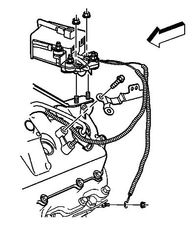
2 4. Remove the fuel injection pump fuel return rubber hose from the junction block (2). Cap the fitting on the block with a 3/8 inch rubber cap (1) to prevent fuel leakage. 2/22

3 5. Attach a rubber hose (1) with a barbed fitting to the fuel injection pump return hose and insert the other end into a 1 gallon clean fuel container (2). 6. Remove the ignition 1 relay using the J Relay Puller Pliers. 3/22
4 7. Remove the glow plug controller/relay. 4/22
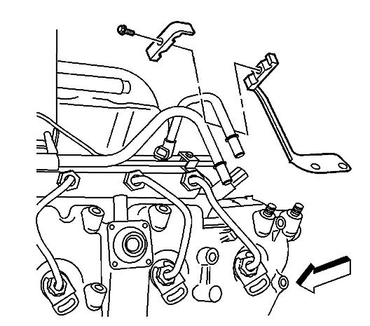
5 8. Remove the fuel line retainers. 5/22

6 9. Remove the banjo bolt (2) from left rear cylinder head. 6/22

7 10. Install the black hose (1) of the J to the left rear cylinder head and install the other end of the hose into one of the J graduated cylinders. 7/22

8 11. Remove the banjo bolt (3) from the leak-off block. 8/22
9 12. Install the other black hose (1) of the J to the leak-off block (2) and install the other end of the hose into another J graduated cylinders. 9/22

10 13. Remove the banjo bolt (4) from the junction block (2). 14. Crank the engine for 15 seconds while observing the fuel pressure relief valve on the junction block for fuel leakage. - If fuel is leaking from the fuel pressure relief valve, replace the fuel pressure relief valve. - If no fuel is leaking from the fuel pressure relief valve, go to step /22
11 15. Crank the engine in 15 second intervals, with one minute cooling time between, until fuel starts to flow into one or both of the J graduated cylinders (1). 16. Elevate the hoses (2) to retain the fuel in the hoses, and empty the graduated cylinders into a suitable container. 17. Install the hoses (2) into 2 of the graduated cylinders (1). 18. Crank the engine for 15 seconds. IMPORTANT: The engine cranking speed must be more than 150 RPM. 19. Measure the quantity of fuel in each of the graduated cylinders. - If there is more than 12 ml of fuel from either cylinder bank, remove the valve cover from that bank. - If there is less than 12 ml from each cylinder bank, replace the fuel injection pump and repeat steps If the fuel injection pump has already been replaced in this repair and there is less than 12 ml of fuel from each bank, go to step /22

12 20. Remove the return line from injectors. IMPORTANT: When the fuel injector pressure lines are removed, debris will fall into the fuel injector inlet fitting. Vacuum the debris from the inlet fitting of the fuel injector. 12/22
. https://my.alldata.")
13 21. Install the four yellow hoses (2) from the J to the injectors (1) and the other end of the hoses into each of the J graduated cylinders. 22. Install the four injector supply lines. Tighten Tighten the supply lines to 44 N.m (32 lb ft). 13/22
14 23. Connect the engine-to-chassis harness connectors to enable the starter. 14/22

15 24. Install the fuel supply hose. Push the hose in until it locks. 25. Install the black hoses from the J into the same container that the fuel injection pump return hose is in. Prime the fuel system 30 times to remove air from the fuel system. Air will be forced out of the system within 2 minutes. 26. Crank the engine in 15 second intervals, with one minute cooling time between, until fuel starts to flow into one or more of the graduated cylinders. 27. Elevate the four hoses to retain the fuel in the hoses, and empty the 4 graduated cylinders into a suitable container. 28. Install the hoses in the graduated cylinders in numerical order. 29. Crank the engine for 15 seconds. IMPORTANT: The engine cranking speed must be more than 150 RPM. 30. Measure the quantity of fuel in each of the graduated cylinders. 15/22
16 - If there is more than 3 ml of fuel flow from any fuel injector(s), replace the high flowing fuel injector(s). - If no fuel injector has a flow of more than 3 ml, install the valve cover. 31. Repeat steps 25 through 30 until no fuel injectors have more than 3 ml of fuel flow. 32. Were both banks of fuel injectors tested with steps 25 through 32? - If the answer is YES, go to step If the answer is NO, go to step Reassemble the fuel return line and valve cover. Refer to applicable procedures. 34. Ensure that the hoses are still installed as they were in steps 10 through Prime the fuel system 30 times to remove the air from the fuel system. Air will be forced out of the system within 2 minutes. 36. Crank the engine in 15 second intervals, with one minute cooling time between, until fuel starts to flow into one or both of the J graduated cylinders (1). 37. Elevate the hoses (2) to retain the fuel in the hoses, and empty the graduated cylinders into a suitable container. 16/22
17 38. Install the hoses (2) into 2 of the graduated cylinders (1). 39. Crank the engine for 15 seconds while observing the fuel pressure relief valve for fuel leaks. If the relief valve leaks, replace the relief valve and repeat steps 36 through 39. IMPORTANT: The engine cranking speed must be more than 150 RPM. 40. Measure the quantity of fuel in each of the graduated cylinders. If there is more than 12 ml of fuel in either of the 2 cylinders, perform steps 25 through 31 on the bank of fuel injectors with the high fuel flow, Then go to step 41. If both of the cylinder have less than 12 ml of fuel, go to step Install all disconnected and removed components. 42. Start and idle the engine. You may have to prime the fuel system before the engine will start. 43. Connect a scan tool. 44. Command the fuel pressure control to 160 MPa with a scan tool. - If the fuel pressure is more than 145 MPa, the system is OK. - If the fuel pressure is unable to increase to more than 145 MPa, replace the fuel injection pump. Fuel Pressure Regulator Graphing 1. Set up the scan tool in the following format: 1.1. Select the Data Display on the scan tool Select Engine Data Select the More softkey 2 times Select the Live Plot softkey Select the Engine Speed, Actual Fuel Rail Pressure, and Desired Fuel Rail Pressure parameters by highlighting each parameter and depressing the ENTER softkey Select the Accept softkey Select the More softkey, then select the Change Min/Max softkey Select the More softkey, and adjust the parameters to the following Min/Max ranges: - The Engine Speed Min/Max range is 0 to 1000 RPM. - The Actual Fuel Rail Pressure Min/Max range is 1.0 to 160 MPa. - The Desired Fuel Rail Pressure Min/Max range is 1.0 to 160 MPa. 2. Start and idle the engine. 17/22
18 18/22
19 19/22
20 3. Observe the live plot for sharp changes in the Actual Fuel Rail Pressure above and below the Desired fuel rail pressure while performing one of the following actions: - Idling the engine. - Shifting the transmission from Park to Drive, and back to Park. - Turning the steering wheel from lock to lock. - Turning the air conditioning ON and OFF. 4. If there is a violent fluctuation in the Actual Fuel Rail pressure, as seen in the third Graphic above, replace the fuel pressure regulator. 20/22
21 21/22
22 22/22
Fuel System Diagnosis
 Page 1 of 6 2001 Chevrolet Malibu Malibu (VIN N) Service Manual Engine Engine Controls - 3.1L (LG8) Diagnostic Information and Procedures Document ID: 704675 Fuel System Diagnosis System Description When
# : Revised Engine Cranks But Does Not Run Diagnostic - (Sep 26, 2003)
") #03-06-04-046: Revised Engine Cranks But Does Not Run - (Sep 26, 2003) Subject: Revised Engine Cranks But Does Not Run Models: 2001-2004 Chevrolet Silverado 2003-2004 Chevrolet Kodiak 2001-2004 GMC Sierra
#03-06-04-046: Revised Engine Cranks But Does Not Run - (Sep 26, 2003) Subject: Revised Engine Cranks But Does Not Run Models: 2001-2004 Chevrolet Silverado 2003-2004 Chevrolet Kodiak 2001-2004 GMC Sierra
Fuel System Diagnosis
 Page 1 of 6 2001 Chevrolet Express Express, Savana (VIN G) Service Manual Engine Engine Controls - 5.0L and 5.7L Diagnostic Information and Procedures Document ID: 720867 Fuel System Diagnosis Circuit
Fuel System Diagnosis
 Page 1 of 6 2004 Chevrolet Chevy K Silverado - 4WD Sierra, Silverado (VIN C/K) Service Manual Engine Engine Controls - 6.6L (LLY) Diagnostic Information and Procedures Document ID: 1460257 Fuel System
Engine Cranks But Does Not Run
 Page 1 of 5 2000 GMC Truck GMC K Sierra - 4WD Sierra, Silverado, Suburban, Tahoe, Yukon (VIN C/K) Service Manual Engine Engine Controls - 4.8L, 5.3L, and 6.0L Diagnostic Information and Procedures Engine
Fuel Pump Electrical Circuit Diagnosis
 Page 1 of 6 Document ID# 599891 2000 Chevrolet Camaro Feedback Print Fuel Pump Electrical Circuit Diagnosis Circuit Description When the ignition switch is ON, the powertrain control
Fuel Pump Electrical Circuit Diagnosis
 1999 Chevrolet/Geo Tahoe - 4WD Fuel Pump Electrical Circuit Diagnosis Refer to Fuel Controls. Circuit Description When the ignition switch is turned ON, the VCM energizes the fuel pump relay which powers
Idle Air Control (IAC) System Diagnosis
 System Diagnosis") 2000 GMC Truck GMC K Sierra - 4WD Idle Air Control (IAC) System Diagnosis Circuit Description The vehicle control module (VCM) controls idle RPM with the idle air control (IAC) valve. To increase idle
2000 GMC Truck GMC K Sierra - 4WD Idle Air Control (IAC) System Diagnosis Circuit Description The vehicle control module (VCM) controls idle RPM with the idle air control (IAC) valve. To increase idle
Idle Air Control (IAC) System Diagnosis
 System Diagnosis") Page 1 of 6 2002 Chevrolet Tahoe - 4WD Avalanche, Escalade, Suburban, Tahoe, Yukon VIN C/K Service Manual Engine Engine Controls - 4.8L, 5.3L, and 6.0L Diagnostic Information and Procedures Document ID:
Page 1 of 6 2002 Chevrolet Tahoe - 4WD Avalanche, Escalade, Suburban, Tahoe, Yukon VIN C/K Service Manual Engine Engine Controls - 4.8L, 5.3L, and 6.0L Diagnostic Information and Procedures Document ID:
Alliant Power Technical Support p f alliantpower.com. Step 1: Visual Inspection of Engine Compartment OK Not Ok Comments
 6.0 L Low Power/All Times Step 1: Visual Inspection of Engine Compartment OK Not Ok Comments Inspect the cooling hoses and connections Inspect the battery cables and connections Inspect the wiring harnesses
Hard Start or No Start Diagnostic Procedures
 Page 1 of 48 2006 PCED 6.0L Diesel SECTION 4: Diagnostic Subroutines Procedure revision date: 05/08/2015 E-Series or F-Super Duty Hard Start or No Start Diagnostic Procedures Printable view of this graphic
Idle Air Control (IAC) System Diagnosis
 System Diagnosis") 2001 Oldsmobile Alero Idle Air Control (IAC) System Diagnosis Circuit Description The idle air control (IAC) valve is located in the throttle body. It consists of a movable pintle, driven by a gear attached
2001 Oldsmobile Alero Idle Air Control (IAC) System Diagnosis Circuit Description The idle air control (IAC) valve is located in the throttle body. It consists of a movable pintle, driven by a gear attached
MASS AIR FLOW (MAF) SENSOR, CHECKING - BOSCH
 SENSOR, CHECKING - BOSCH") 2004 Audi A6 Sedan (4B2) V6-2.7L Turbo (BEL) Vehicle > Powertrain Management > Computers and Control Systems > Testing and Inspection > Component Tests and General Diagnostics > Component Tests > Mass
2004 Audi A6 Sedan (4B2) V6-2.7L Turbo (BEL) Vehicle > Powertrain Management > Computers and Control Systems > Testing and Inspection > Component Tests and General Diagnostics > Component Tests > Mass
Fuel System Diagnosis
 2000 Chevrolet Corvette Corvette (VIN Y) Service Manual Document ID: 609667 Page 1 of 7 Fuel Diagnosis (1) Fuel Feed Pipe (2) Auxiliary Fuel Feed Rear Pipe (left tank to jet pump) (3) Auxiliary Fuel Return
DTC P0341 Camshaft Position (CMP) Sensor Performance
 Sensor Performance") Page 1 of 5 1999 Buick Century Century, Regal VIN W Service Manual Document ID: 345654 DTC P0341 Camshaft Position (CMP) Sensor Performance Circuit Description During cranking, the Ignition Control Module
Page 1 of 5 1999 Buick Century Century, Regal VIN W Service Manual Document ID: 345654 DTC P0341 Camshaft Position (CMP) Sensor Performance Circuit Description During cranking, the Ignition Control Module
DTC P1431 Fuel Level Sensor 2 Performance
 Page 1 of 8 Document ID# 610929 2000 Chevrolet Corvette Feedback Print DTC P1431 Fuel Level Sensor 2 Performance Circuit Description The right fuel level sensor 2, mounted in the rear
2002 Buick Rendezvous - AWD
 2002 Buick Rendezvous - AWD DTC P0410 Description The control module activates the secondary air injection (AIR) system by grounding both the pump relay and the vacuum control solenoid control circuits.
Fuel Injector Replacement (Right Bank) EN Injector Bore and Sleeve Cleaning Kit J Fuel Injector Removal Tool
 EN Injector Bore and Sleeve Cleaning Kit J Fuel Injector Removal Tool") Page 1 of 7 Home Account Contact ALLDATA Log Out Help DAN GRIMWOOD DAN GRIMWOOD00002 Select Vehicle New TSBs Technician's Reference Component Search: OK 2002 Chevy Truck C 2500 Truck 2WD V8-6.6L DSL Turbo
Page 1 of 7 Home Account Contact ALLDATA Log Out Help DAN GRIMWOOD DAN GRIMWOOD00002 Select Vehicle New TSBs Technician's Reference Component Search: OK 2002 Chevy Truck C 2500 Truck 2WD V8-6.6L DSL Turbo
P2284 REQUESTED INFORMATION. Pinpoint Test Ao: Injector Control Pressure Too High. Print Ford Pickup 6.0L Eng F250 Super Duty.
 Print 2004 Ford Pickup 6.0L Eng F250 Super Duty P2284 REQUESTED INFORMATION Pinpoint Test Ao: Injector Control Pressure Too High Introduction Signal Function The injector control pressure is determined
P249E-CLOSED LOOP SCR REDUCTANT INJECTION CONTROL AT LIMIT - FLOW TOO HIGH
 2015 - DJ - RAM 2500 PICKUP - 6.7L I6 CUMMINS TURBO DIESEL P249E-CLOSED LOOP SCR REDUCTANT INJECTION CONTROL AT LIMIT - FLOW TOO HIGH For a complete wiring diagram, refer to the Wiring Information. When
Secondary air system. Secondary air system, function/components
 Page 1 of 26 26-41 Secondary air system Secondary air system, function/components The secondary air system permits faster warm-up and thus makes the catalytic converter ready for operation sooner after
Fuel System Diagnosis
 Page 1 of 9 1999 Chevrolet Express Express, Savana (VIN G) Service Manual Engine Engine Controls - 5.0L and 5.7L Diagnostic Information and Procedures Document ID: 412957 Fuel System Diagnosis Circuit
DTC P0102 Mass Air Flow (MAF) Sensor Circuit Low Frequency
 Sensor Circuit Low Frequency") Page 1 of 5 1997 Pontiac Grand Prix Grand Prix (VIN W) Service Manual Engine Engine Controls - 3.8L Diagnostic Information and Procedures Document ID: 106986 DTC P0102 Mass Air Flow (MAF) Sensor Circuit
Page 1 of 5 1997 Pontiac Grand Prix Grand Prix (VIN W) Service Manual Engine Engine Controls - 3.8L Diagnostic Information and Procedures Document ID: 106986 DTC P0102 Mass Air Flow (MAF) Sensor Circuit
DTC P0174 Fuel Trim System Lean Bank 2
 2000 Chevrolet/Geo S10 Pickup - 4WD DTC P0174 Fuel Trim System Lean Bank 2 Circuit Description In order to provide the best possible combination of driveability, fuel economy, and emission control, the
DTC P1415 Secondary Air Injection (AIR) System Bank 1
 System Bank 1") Page 1 of 5 2000 GMC Truck GMC K Sierra - 4WD Sierra, Silverado, Suburban, Tahoe, Yukon (VIN C/K) Service Manual Document ID: 546887 DTC P1415 Secondary Air Injection (AIR) System Bank 1 Circuit Description
Page 1 of 5 2000 GMC Truck GMC K Sierra - 4WD Sierra, Silverado, Suburban, Tahoe, Yukon (VIN C/K) Service Manual Document ID: 546887 DTC P1415 Secondary Air Injection (AIR) System Bank 1 Circuit Description
Note: The engine may start, but you may still have high leakoff within the high-pressure fuel system. NOTICE
 Introduction There have been isolated occurrences of excessive fuel leakage past the electronic unit injectors on some engines. Accelerated wear on the delivery valve results in an increased leak rate.
1 of :23
 1 of 8 2013.02.09 03:23 Published: 08-Jun-2012 Electronic Engine Controls - TDV8 3.6L Diesel - Electronic Engine Controls 3.6L (TdV8) Diesel Diagnosis and Testing Overview This section covers the components
Dtc P128E. Print Chevrolet Silverado 6.6L Eng 2500 Hd. 1Search P128E REQUESTED INFORMATION. Diagnostic Instructions
 Print 1Search REQUESTED INFORMATION Dtc Diagnostic Instructions 2012 Chevrolet Silverado 6.6L Eng 2500 Hd Perform the Diagnostic System Check - Vehicle prior to using this diagnostic procedure. Review
Fuel System Diagnosis
 1996 Chevrolet Impala Caprice, Impala, Roadmaster (VIN B) Service Manual Engine Engine Controls - 4.3L (Caprice Only) and 5.7L Diagnostic Information and Procedures Document ID: 37723 Fuel System Diagnosis
Common Rail Injector
 Common Rail Injector Installation Instructions & Information Common Rail Injector General Information WARNING WARNING CAUTION Fuel may be returned at highly elevated temperatures. Wear safety glasses and
2001 Audi TT Quattro ENGINE PERFORMANCE' 'System & Component Testing
 FUEL SYSTEM WARNING: ALWAYS release fuel pressure before disconnecting fuel injection-related component. DO NOT allow fuel to contact engine or electrical components. FUEL INJECTOR TEST Fuel Injector Electrical
Fuel System Diagnosis
 Page 1 of 8 Document ID# 104786 1997 Chevrolet Corvette Feedback Print Fuel Diagnosis (1) Fuel Pressure Gauge Bleed Hose (2) J 37287 Fuel Line Shut-off Adapters (3) Return Pipe (4) Feed
On Board Diagnostics II Diesel PCED
 Page 1 of 13 1. Visual Engine/Chassis Inspection This is a visual inspection to check the general condition of the engine and look for obvious causes of hard start or no start conditions. Inspect fuel
DTC P0118 Engine Coolant Temperature (ECT) Sensor Circuit High Voltage
 Sensor Circuit High Voltage") Document ID# 546741 2000 Chevrolet Chevy K Silverado - 4WD Print DTC P0118 Engine Coolant Temperature (ECT) Sensor Circuit High Voltage Circuit Description The engine coolant temperature
Document ID# 546741 2000 Chevrolet Chevy K Silverado - 4WD Print DTC P0118 Engine Coolant Temperature (ECT) Sensor Circuit High Voltage Circuit Description The engine coolant temperature
On Board Diagnostics II Diesel PCED
 Page 1 of 19 1999 PCED On Board Diagnostics II Diesel SECTION 4: Diagnostic Subroutines Performance Diagnostic Procedures Page 2 of 19 Page 3 of 19 Page 4 of 19 Page 5 of 19 1. Visual Engine/Chassis Inspection
Document ID# Chevrolet Corvette
 Page 1 of 6 Document ID# 610892 2000 Chevrolet Corvette Feedback Print D T C P 0 4 6 2 F u e l L e v e l S e n s o r C i r c u i t L o w V o l t a g e C i r c u i t D e s c r i p t i
DTC P0336 Crankshaft Position (CKP) Sensor Performance
 Sensor Performance") Page 1 of 5 1998 Chevrolet Chevy K Pickup - 4WD Chevy Pickup, GMC Pickup, Suburban, Tahoe, Yukon (VIN C/K) Service Manual Document ID: 188141 DTC P0336 Crankshaft Position (CKP) Sensor Performance Circuit
Page 1 of 5 1998 Chevrolet Chevy K Pickup - 4WD Chevy Pickup, GMC Pickup, Suburban, Tahoe, Yukon (VIN C/K) Service Manual Document ID: 188141 DTC P0336 Crankshaft Position (CKP) Sensor Performance Circuit
DTC P1515 Control Module Throttle Actuator Position Performance
 Page 1 of 6 Document ID# 317225 1999 Chevrolet/Geo Corvette Print DTC P1515 Control Module Throttle Actuator Position Performance Refer to Cell 20: TP and APP Sensors for complete circuit
P0088-FUEL RAIL PRESSURE TOO HIGH
 2008 - KA - DODGE NITRO - 2.8L 4 CYL TURBO DIESEL 28 - DTC-Based Diagnostics/MODULE, Engine Control (ECM)/Diagnosis and Testing P0088- RAIL TOO HIGH BATT A0 30 RELAY- AUTO SHUT DOWN MODULE- TOTALLY INTEGRATED
Scan Tool Does Not Communicate with Class 2 Device (W/O Immobilizer)
") Page 1 of 5 2002 GMC Truck Envoy - 4WD Bravada, Envoy, TrailBlazer (VIN S/T) Service Manual Body and Accessories Data Link Communications Diagnostic Information and Procedures Document ID: 754548 Scan
Page 1 of 5 2002 GMC Truck Envoy - 4WD Bravada, Envoy, TrailBlazer (VIN S/T) Service Manual Body and Accessories Data Link Communications Diagnostic Information and Procedures Document ID: 754548 Scan
DTC P0201, P0202, P0203, P0204, P0205, P0206, P0207, or P0208
 Page 1 of 9 2004 Chevrolet Chevy K Silverado - 4WD Sierra, Silverado (VIN C/K) Service Manual Document ID: 850614 DTC P0201, P0202, P0203, P0204, P0205, P0206, P0207, or P0208 Circuit Description The fuel
Disconnect the APP sensor harness connector. See Fig. 4. Remove the accelerator pedal mounting nuts. Remove the APP assembly.
 ENGINE CONTROLS - REMOVAL, OVERHAUL & INSTALLATION - 6.6L DIESEL... Page 1 of 41 FUEL SYSTEMS ACCELERATOR PEDAL POSITION SENSOR Removal & Installation Disconnect the APP sensor harness connector. See Fig.
Intake Manifold Tuning (IMT)
") Page 1 of 11 24-154 Intake Manifold Tuning (IMT) system Notes: The change-over of the manifold from long to short intake path occurs at approx. 4500 RPM. Component location page 24-1 Required special tools
Page 1 of 11 24-154 Intake Manifold Tuning (IMT) system Notes: The change-over of the manifold from long to short intake path occurs at approx. 4500 RPM. Component location page 24-1 Required special tools
QuickServe Online ( ) ISB6.7 CM2350 B101 Service Manual
 ISB6.7 CM2350 B101 Service Manual") Page 1 of 31 (/qs3/pubsys2/xml/en/manual/2883567/2883567-titlepage.html) Select Service Tools Recommended Cummins Service Tools 0.043 inch orificed diagnostic fuel line, Part Number 3164621 Diagnostic
Page 1 of 31 (/qs3/pubsys2/xml/en/manual/2883567/2883567-titlepage.html) Select Service Tools Recommended Cummins Service Tools 0.043 inch orificed diagnostic fuel line, Part Number 3164621 Diagnostic
Fuel Metering System Component Description
 1999 Chevrolet/Geo Tahoe - 4WD Fuel Metering System Component Description Purpose The function of the fuel metering system is to deliver the correct amount of fuel to the engine under all operating conditions.
DTC P1223, P1226, P1229, P1232, P1235, P1238, P1241, or P1244
 Page 1 of 5 005 Chevrolet Kodiak C-Series (Conventional) C/C5 Kodiak, TopKick C-Series Service Manual Document ID: 16600 DTC P13, P16, P1, P13, P135, P138, P11, or P1 Circuit Description The engine control
Fuel Injector Control Module (FICM ) Low Voltage
 Low Voltage") Page 1 of 6 Year = 2006 Model = F-Super Duty Engine = VIN = Fuel Injector Control Module (FICM ) Low Voltage Circuit Function The FICM requires a 12-volt power source. The FICM receives power from the
Page 1 of 6 Year = 2006 Model = F-Super Duty Engine = VIN = Fuel Injector Control Module (FICM ) Low Voltage Circuit Function The FICM requires a 12-volt power source. The FICM receives power from the
 1 of 6 3/7/2013 9:56 AM 2002 Chevrolet TrailBlazer - 4WD Bravada, Envoy, TrailBlazer VIN S/T Service Manual DTC P1481 Circuit Description The powertrain control module (PCM) uses the cooling fan speed
6.0L HARD START / LONG CRANK / NO START TSB LOW INJECTOR CONTROL PRESSURE (ICP)
") 6.0L HARD START / LONG CRANK / NO START TSB 08-18-6 LOW INJECTOR CONTROL PRESSURE (ICP) FORD: 2005 Excursion 2005-2007 F-Super Duty 2005-2008 E-350, E-450 This article supersedes TSBs 08-9-9 and 05-12-3
6.0L HARD START / LONG CRANK / NO START TSB 08-18-6 LOW INJECTOR CONTROL PRESSURE (ICP) FORD: 2005 Excursion 2005-2007 F-Super Duty 2005-2008 E-350, E-450 This article supersedes TSBs 08-9-9 and 05-12-3
Oregon Fuel Injection
 2003 2007 Dodge 5.9L Diesel Diagnostics In order to do proper diagnostics you will need a scan tool and some special tools available from Miller Special Tools http://millerspecialtools.spx.com. High Pressure
Low fuel pressure will damage injectors 6.0 POWERSTROKE FUEL PRESSURE TESTING AND TIPS
 Low fuel pressure will damage injectors 6.0 POWERSTROKE FUEL PRESSURE TESTING AND TIPS WHAT CAUSES INJECTOR FAILURE This chart is from FORD. As you can see, we need to do our part to ensure the customer
Malfunction Criteria and Threshold Value Adaptive value. Secondary Parameters with Enable Conditions. >50.8 S Engine load 9-45% Delta fuel adaptation
 DTC Error Message P0171 System Too Lean (Bank 1) Diagnostic Procedure Check fuel pump delivery and quantity. Refer to page 126. Check Fuel pressure regulator and residual pressure. Refer to Fuel Injection
SECTION 4: Diagnostic Subroutines. Table of Contents
 SECTION 4: Diagnostic Subroutines Table of Contents Contents PAGE Hard Start/No Start Diagnostic Procedures... 4-2 1. Visual Engine/Chassis Inspection... 4-4 2. Check Engine Oil Level... 4-5 3. Glow Plug
Oregon Fuel Injection
 2001 2006 Dodge Mercedes - Freightliner Sprinter Diagnostics In order to do proper diagnostics you will need a scan tool and some special tools available from Mopar Special Tools http://mopar.snapon.com.
DTC P3401, P3425, P3441, or P3449
 Page 1 of 5 2008 Chevrolet Avalanche - 4WD Avalanche, Escalade, Suburban, Tahoe, Yukon VIN C/K Service Manual Document ID: 1914310 DTC,,, or Diagnostic Instructions Perform the Diagnostic System Check
Miata - Workshop Manual - Engine
 Page 1 of 8 2003 - Miata - Workshop Manual - Engine NO.6 CRANKS NORMALLY BUT WILL NOT START 6 Cranks normally but will not start Starter cranks engine at normal speed but engine will not run. DESCRIPTION
DJ - RAM 2500 PICKUP - 6.7L I6 CUMMINS TURBO DIESEL
 2013 - DJ - RAM 2500 PICKUP - 6.7L I6 CUMMINS TURBO DIESEL 1 P202E-(DIESEL EXHAUST FLUID) REDUCTANT PERFORMANCE MODULE- POWERTRAIN CONTROL SIGNAL 77 K428 DB RETURN 53 C2 K426 DB/LG 1 SIGNAL 2 RETURN -
PRELIMINARY INSPECTION & ADJUSTMENTS
 PRELIMINARY INSPECTION & ADJUSTMENTS VISUAL INSPECTION Most driveability problems in the engine control system result from faulty wiring, poor electrical connections or leaking air and vacuum hose connections.
ON-VEHICLE INSPECTION
 Last Modified: 4-26-2007 Service Category: Engine/Hybrid System 1.6 G Section: Engine Mechanical Model Year: 2007 Model: 4Runner Doc ID: RM0000017L8004X Title: 1GR-FE ENGINE MECHANICAL: ENGINE: ON-VEHICLE
HVAC Compressor Clutch Does Not Engage
 Page 1 of 6 2004 Pontiac GTO GTO (VIN V) Service Manual HVAC HVAC Systems - Manual Diagnostic Information and Procedures Document ID: 1378425 HVAC Compressor Clutch Does Not Engage Test Description The
International VT 275 Engine Program II: Hard Start/No Start & Performance Diagnostics
 A NAVI STAR C O M PANY International VT 275 Engine Program II: Hard Start/No Start & Performance Diagnostics Study Guide TMT-120615 2006 International Truck and Engine Corporation, 4201 Winfield Road,
Symptom: P0068-MANIFOLD PRESSURE/THROTTLE POSITION CORRELA- TION - VACUUM LEAK DETECTED
 Symptom: P0068-MANIFOLD PRESSURE/THROTTLE POSITION CORRELA- TION - VACUUM LEAK DETECTED When Monitored and Set Condition: VAC- UUM LEAK DETECTED When Monitored: During all drive modes. Set Condition: If
DI 3 ENGINE DIAGNOSTICS DI00H 22 PRE CHECK
 PRECHECK DI3 DI00H22 1. DIAGNOSIS SYSTEM (a) Description When troubleshooting OBD II vehicles, the only difference from the usual troubleshooting procedure is that you connect to the vehicle the OBD II
DTC P2440 SECONDARY AIR INJECTION SYSTEM SWITCHING VALVE STUCK OPEN BANK1 DTC P2441 SECONDARY AIR INJECTION SYSTEM SWITCHING VALVE STUCK CLOSE BANK1
 DIAGNOSTICS SFI SYSTEM (2ZZ GE) (May, 2003) DTC P2440 SECONDARY AIR INJECTION SYSTEM SWITCHI VALVE STUCK OPEN BANK1 05 575 05DWI 01 DTC P2441 SECONDARY AIR INJECTION SYSTEM SWITCHI VALVE STUCK CLOSE BANK1
DTC P0172 Fuel Trim System Rich
 Page 1 of 6 1997 Chevrolet Cavalier Cavalier, Sunfire (VIN J) Service Manual Document ID: 47788 DTC P0172 Fuel Trim System Rich System Description A Closed Loop air/fuel metering system is used to provide
DTC P1351 Ignition Coil Control Circuit High Voltage
 Page 1 of 5 1996 Chevrolet Chevy K Pickup - 4WD Chevy Pickup, GMC Pickup, Suburban, Tahoe, Yukon (VIN C/K) Service Manual Document ID: 34079 DTC P1351 Ignition Coil Control Circuit High Voltage Circuit
DTC P0171 SYSTEM TOO LEAN (BANK 1) DTC P0174 SYSTEM TOO LEAN (BANK 2)
 DTC P0174 SYSTEM TOO LEAN (BANK 2)") 05498 DIAGNOSTICS DTC P0171 SYSTEM TOO LEAN (BANK 1) 05EXR06 DTC P0172 SYSTEM TOO RICH (BANK 1) DTC P0174 SYSTEM TOO LEAN (BANK 2) DTC P0175 SYSTEM TOO RICH (BANK 2) CIRCUIT DESCRIPTION The fuel trim is
05498 DIAGNOSTICS DTC P0171 SYSTEM TOO LEAN (BANK 1) 05EXR06 DTC P0172 SYSTEM TOO RICH (BANK 1) DTC P0174 SYSTEM TOO LEAN (BANK 2) DTC P0175 SYSTEM TOO RICH (BANK 2) CIRCUIT DESCRIPTION The fuel trim is
DTC P0102 Mass Air Flow (MAF) Sensor Circuit Low Frequency
 Sensor Circuit Low Frequency") Seite 1 von 5 Document ID# 187823 1998 Chevrolet/Geo Tahoe - 2WD Print DTC P0102 Mass Air Flow (MAF) Sensor Circuit Low Frequency Circuit Description The mass air flow (MAF) sensor is
Seite 1 von 5 Document ID# 187823 1998 Chevrolet/Geo Tahoe - 2WD Print DTC P0102 Mass Air Flow (MAF) Sensor Circuit Low Frequency Circuit Description The mass air flow (MAF) sensor is
F - BASIC TESTING Infiniti G20 INTRODUCTION PRELIMINARY INSPECTION & ADJUSTMENTS VISUAL INSPECTION MECHANICAL INSPECTION
 F - BASIC TESTING 1992 Infiniti G20 1992 ENGINE PERFORMANCE Infiniti Basic Diagnostic Procedures G20, M30, Q45 INTRODUCTION The following diagnostic steps will help prevent overlooking a simple problem.
High Pressure Oil Pump: Testing and Inspection
 2003 Ford Truck F 250 2WD Super Duty V8-7.3L DSL Turbo VIN F Page 1 High Pressure Oil Pump: Testing and Inspection Technician High Pressure Pump Guide For the 7.3 Power Stroke Engine Pump Leak Repair High
ELECTRONIC FUEL INJECTION
 Table of Contents ELECTRONIC FUEL INJECTION Section 3B - Troubleshooting and Diagnostics TROUBLESHOOTING AND DIAGNOSTICS Specifications........................... 3B-1 Special Tools...........................
BASIC DIAGNOSTIC PROCEDURES
 BASIC DIAGNOSTIC PROCEDURES 2001 Chevrolet Camaro 2001 ENGINE PERFORMANCE Basic Diagnostic Procedures - Cars Except Metro & Prizm MODEL IDENTIFICATION MODEL IDENTIFICATION Body Code (1) Model C... Park
Fuel System (Central SFI)
") Page 1 of 6 1997 GMC Truck GMC K Pickup - 4WD Chevy Pickup, GMC Pickup, Suburban, Tahoe, Yukon (VIN C/K) Service Manual Engine Engine Controls - 5.0L, 5.7L, and 7.4L Description and Operation Document
Page 1 of 6 1997 GMC Truck GMC K Pickup - 4WD Chevy Pickup, GMC Pickup, Suburban, Tahoe, Yukon (VIN C/K) Service Manual Engine Engine Controls - 5.0L, 5.7L, and 7.4L Description and Operation Document
DFIT Diagnostics Reference Guide
 DFIT Diagnostics Reference Guide About This Guide The purpose of this guide is to aid you in diagnosing a vehicle s injectors based on the test results. On the following pages, locate the screen that best
The engine is running. DTC P0351, P0352, P0353, and P0354 run continuously once the above condition has been met.
 Page 1 of 6 DTC P0351-P0354 Circuit Description DTCs P0351 through P0354 Ignition Coil Primary/Secondary Feedback Circuit diagnostic monitors the primary circuitry of individual ignition coils for the
On Board Diagnostics II Diesel PCED
 Page 1 of 16 2001 PCED On Board Diagnostics II Diesel SECTION 4A: Diagnostic Subroutines F250-550 and Econoline Procedure revision date: 08/12/2004 Performance Diagnostic Procedures 1. Visual Engine/Chassis
Intake Manifold Replacement
 Page 1 of 14 2004 Chevrolet TrailBlazer - 4WD Bravada, Envoy, Rainier, TrailBlazer (VIN S/T) Service Manual Engine Engine Mechanical - 4.8L, 5.3L, and 6.0L Repair Instructions - On Vehicle Document ID:
P2459-DIESEL PARTICULATE FILTER REGENERATION TOO FREQUENT
 2014 - DP - RAM 4500/5500 CAB CHASSIS - 6.7L I6 CUMMINS TURBO DIESEL P2459-DIESEL PARTICULATE FILTER REGENERATION TOO FREQUENT The engine aftertreatment system monitors the soot load in the Diesel Particulate
Powertrain Control/Emissions Diagnosis
 Powertrain Control/Emissions Diagnosis 1999 On Board Diagnostics II Diesel SECTION 4: Diagnostic Subroutines SECTION 4: Diagnostic Subroutines Hard Start/ Start Diagnostic Procedures 1. Visual Engine/Chassis
Preliminary Information
 Preliminary Information Bulletin No.: PIT5510C Published date: 07/21/2017 PIT5510C Fuel Gauge Displays Empty / Low Fuel Light On / DTC P2636 Models Brand: Model: Model Years: from VIN: to Engine: Transmissions:
F - BASIC TESTING Article Text 1992 Dodge Colt For a a a a a Copyright 1998 Mitchell Repair Information Company, LLC Saturday, April 27, :48PM
 Article Text ARTICLE BEGINNING 1992 ENGINE PERFORMANCE Chrysler Motors/Mitsubishi Basic Diagnostic Procedures Chrysler Motors: Colt, Colt 200, Summit Mitsubishi: Mirage INTRODUCTION The following diagnostic
Enhanced Ignition System Diagnosis
 Page 1 of 7 1998 Chevrolet Chevy K Pickup - 4WD Chevy Pickup, GMC Pickup, Suburban, Tahoe, Yukon (VIN C/K) Service Manual Engine Engine Controls - 5.0L and 5.7L Diagnostic Information and Procedures Enhanced
On Board Diagnostics II A PCED
 1998 PCED On Board Diagnostics II A SECTION 5A: Pinpoint Tests HA: Natural Gas Fuel Control HA: Introduction HA30 DTCS P05, P0141, P0155 AND P0161: HO2S HEATER SIGNAL CIRCUIT IS OPEN, SHORTED TO GROUND,
DODGE SRT-4 PART NUMBER P (with Turbo Toys) P (without Turbo Toys) P (Stage 2 to Stage 3R Upgrade Kit)
 P (without Turbo Toys) P (Stage 2 to Stage 3R Upgrade Kit)") INFORMATION SHEET Stage 3R Turbo Upgrade Kit Components (1) Stage 3R PCM (4) 682 cc/min Fuel Injectors* (1) 3.0 bar MAP Sensor* (1) 3.0 bar TIP Sensor* (1) Block-off Connector for PCM (1) Mopar TD05HR
INFORMATION SHEET Stage 3R Turbo Upgrade Kit Components (1) Stage 3R PCM (4) 682 cc/min Fuel Injectors* (1) 3.0 bar MAP Sensor* (1) 3.0 bar TIP Sensor* (1) Block-off Connector for PCM (1) Mopar TD05HR
SYSTEM & COMPONENT TESTING
 SYSTEM & COMPONENT TESTING 2001 Chevrolet Camaro 2001 ENGINE PERFORMANCE System & Component Testing - Cars Except Metro & Prizm MODEL IDENTIFICATION Vehicle model is identified by fourth character of Vehicle
Printable View Page 1 of 18 11/26/2013 Year = 2011 Model = E
 Page 1 of 18 Year = 2011 Model = Escape Engine = VIN = IDS Version = t Available Misfire Detection Monitor WARNING: Crown Victoria Police Interceptor vehicles equipped with fire suppression system, refer
DIAGNOSTIC TROUBLE CODE CHART
 DIAGNOSTIC TROUBLE CODE CHART 05 35 HINT: As for the vehicle for MEXICO, refer to Repair Manual 2003 COROLLA MATRIX (Pub. No. RM940U). Parameters listed in the chart may not be exactly the same as your
On Board Diagnostics II A PCED
 Page 1 of 5 1998 PCED On Board Diagnostics II A SECTION 5A: Pinpoint Tests KE: Idle Air Control (IAC) Valve KE: Introduction KE1 IDLE CONCERNS OR STALLS: RUN KOER SELF-TEST AND OUTPUT CONTINUOUS MEMORY
ME: Fuel Pump Control - High Pressure Fuel Injection Pump
 Page 1 of 6 2008 Ford F-250 Super Duty : Diagnostics > 6.4L Diesel > Pinpoint Tests > ME: Fuel Pump Control - High Pressure Fuel Injection Pump ME: Fuel Pump Control - High Pressure Fuel Injection Pump
Diagnostic Trouble Code (DTC) memory, checking and erasing
 memory, checking and erasing") Page 1 of 49 01-12 Diagnostic Trouble Code (DTC) memory, checking and erasing Check DTC Memory (function 02) - Connect VAS5051 tester Page 01-7 and select vehicle system "01 - Engine electronics". Engine
Page 1 of 49 01-12 Diagnostic Trouble Code (DTC) memory, checking and erasing Check DTC Memory (function 02) - Connect VAS5051 tester Page 01-7 and select vehicle system "01 - Engine electronics". Engine
M-9424-M50B 2012 Boss 302 Intake Manifold INSTALLATION INSTRUCTIONS
 !!! PLEASE READ ALL OF THE FOLLOWING INSTRUCTIONS CAREFULLY PRIOR TO INSTALLATION. WARNING: CUSTOM CALIBRATION REQUIRED! CALIBRATION NOT INCLUDED! KIT CONTENTS: 1) Intake Manifold Assembly 2) Assembly
EVAP system, servicing
 Page 1 of 65 20-130 EVAP system, servicing EVAP system components 1 - Cap nut 10 Nm 2 - Cover 3 - Stud For EVAP canister 15 Nm 4 - Sealing piece 5 - Bleed line To EVAP canister purge regulator valve -
RR 2T and X - Trainer oil injection and wiring trouble shooting guide
 RR 2T and X - Trainer oil injection and wiring trouble shooting guide General information 1. Before performing the following diagnostic procedures, check wiring plugs and terminals for corrosion and secure
DIAGNOSTIC INFORMATION AND PROCEDURES > CHARGING SYSTEM TEST
 Page 1 of 5 Service Manual: BATTERY, CHARGING SYSTEM AND Print Date: STARTING SYSTEM DIAGNOSTIC INFORMATION AND PROCEDURES > CHARGING SYSTEM TEST Charging System Test 2005 Pontiac Montana SV6 3.5L Eng
Oxygen sensor control,
 Page 1 of 37 24-71 Oxygen sensor control, checking Oxygen sensor and oxygen sensor control before catalytic converter, checking Special tools and equipment - or VAG1526A VAG1594A VAG1598/31 VAS5051 with
DTC P0341 Camshaft Position (CMP) Sensor Performance
 Sensor Performance") Page 1 of 7 1997 Buick Riviera Aurora, Riviera (VIN G) Service Manual Document ID: 53298 DTC P0341 Camshaft Position (CMP) Sensor Performance Circuit Description The camshaft position PCM input is produced
Page 1 of 7 1997 Buick Riviera Aurora, Riviera (VIN G) Service Manual Document ID: 53298 DTC P0341 Camshaft Position (CMP) Sensor Performance Circuit Description The camshaft position PCM input is produced
NCT-1000 Users Manual
 NCT-000 Users Manual NCT 000 KIT 3 6 5 9 0 7 8 0 5 6 7 8 9 3 NCT-000 KIT. TOOL CASE. RAIL PLUG (mm) 5ea ( for spare) 3. RAIL PLUG (mm) 5ea ( for spare). FLASK & HOLDER ea 5. VISIBLE TUBE ea 6. INJECTOR
DTC P0134 OXYGEN SENSOR CIRCUIT NO ACTIVITY DETECTED (BANK 1 SENSOR 1)
") 05 120 05CRQ 02 DTC P0134 OXYGEN SENSOR CIRCUIT NO ACTIVITY DETECTED (BANK 1 SENSOR 1) CIRCUIT DESCRIPTION Refer to DTC P0130 on page 05 101. DTC No. DTC Detecting Condition Trouble Area P0134 After engine
05 120 05CRQ 02 DTC P0134 OXYGEN SENSOR CIRCUIT NO ACTIVITY DETECTED (BANK 1 SENSOR 1) CIRCUIT DESCRIPTION Refer to DTC P0130 on page 05 101. DTC No. DTC Detecting Condition Trouble Area P0134 After engine
Blue Bird Vision. Compressed Natural Gas (CNG) Service Manual
 Service Manual") Blue Bird Vision Compressed Natural Gas (CNG) Table of Contents Foreward... 1 Introduction... 1 CNG System Overview... 1 ROUSH CleanTech Technical Assistance... 1 Safety Information... 1 Alert Messages...
Blue Bird Vision Compressed Natural Gas (CNG) Table of Contents Foreward... 1 Introduction... 1 CNG System Overview... 1 ROUSH CleanTech Technical Assistance... 1 Safety Information... 1 Alert Messages...
Document ID# Chevrolet Chevy Suburban - 4WD
 Page 1 of 8 Document ID# 757392 2003 Chevrolet Chevy Suburban - 4WD Print DTC C0455 Circuit Description The steering wheel position sensor (SWPS) provides one analog signal and 3 digital