Industrial Pump Catalog
|
|
|
- Abel Walker
- 5 years ago
- Views:
Transcription

1 Industrial Pump Catalog
2 Contents Why Corken? i-5 About This Catalog i-6 Hydraulic / Material Selection Instructions i-6 Hydraulic Selection / Overview Graph i-7 Coro-Vane Series (Industrial Vane Pump) Contents Sabre Series (Stainless Steel Vane Pump) Contents SC Series (Side Channel Pump) Contents Coro-Flo (Regenerative Turbine Pump) Contents Appendix Contents i-3
3 Why Corken? For decades Corken had specialized in the transfer of hazardous, non-lubricating liquefied gases and low viscosity liquids. We have thrived on specialty applications that have been troublesome for more common pump designs. If you are wondering whether Corken offers a pump for your needs, here is a list of triggers that describe where the Corken pump excels: THIN LIQUIDS AND LIQUEFIED GASES This includes anything from solvents to ammonia and carbon dioxide. Corken s pumps are designed to handle these non-lubricating hard-to-seal liquids. HIGH HEAD, LOW FLOW Corken pumps fit in these applications where a standard centrifugal pump is not as efficient. LOW NPSH REQUIREMENTS If you have an application which has caused nothing but headaches due to suction piping limitations, Corken could have the solution for you. New pump offerings in the Corken line can handle NPSH as low as 1 foot in many circumstances. MAINTENANCE PROBLEMS Corken s unique pump designs minimize maintenance. On the occasion when maintenance is necessary, our simple designs make repair hassle free. ENTRAINED VAPORS OR VAPOR LOCK Corken's SC series side channel pump is forgiving when handling boiling or other aerated liquids. Gas content is acceptable up to 5% while most centrifugal pumps lose efficiency beyond 3 to 5%. SEALING DIFFICULTIES Corken pumps come with a variety of seal options and flexibility. Sealless models are offered as well. PULSATION PROBLEMS Corken s entire pump offering provides smooth even flow, which is advantageous in applications where problems have arisen or could rise due to pulsation caused by a pump. QUALITY CUSTOMER CARE It is our goal at Corken to provide you with quality personal service. We believe that it is this primary objective that has made Corken a leader in the industries that it has served over its 75 year history. We will continually strive to identify ways in which we can improve ourselves and avoid complacency. i-5
4 About This Catalog It is most likely that you have referred to our Industrial Pump catalog for one of two basic reasons. Either you wish to determine whether one of our pumps can handle a specific application, or you are searching for information on a specific model. This catalog is designed to help you perform either of these tasks. 1. If you wish to select a pump for your application, move on to the section below and we will guide you through the selection process. 2. If you know the model or design of Corken equipment for which you desire information, turn to the table of contents on page i-3 or the tab corresponding to your particular model and we will lead you to the proper page. Hydraulic / Material Selection The Hydraulic Selection / Overview Graph is intended to give you an overview of our hydraulic range as well as aid you in determining which of our pump products will best fit your current needs. Each section in our catalog is color coded in relation to this graph to simplify your selection process. When reading this graph please keep in mind that the reference liquid is water. Liquids with viscosities and specific gravities that differ from water will not necessarily reflect the same flow rates and pressures. Nevertheless, since the purpose of this graph is to get you going in the right direction, it should prove more than adequate. Please note that differential pressure (psi) is provided on the left of the graph while differential head (ft) is provided on the right. The calculation that ties the two values together is: Head In Feet = (2.31) x (PSI) Specific Gravity Specific Gravity of Water = 1. i-6

5 Hydraulic / Material Requirement Selection 1 HYDRAULIC SELECTION / OVERVIEW GRAPH 5
6 Coro-Vane Series 1 CONTENTS Industrial Vane Pump Model Options Form 49A Brochure Industrial Sealed Pump Form 491 Brochure Industrial Magnetic Drive Pump Alternate Drive Options Industrial Vane Pump Model Selection Is the Industrial Vane Series Right for Your Application? Sizing Worksheet Overview of Performance Range Instructions for Selection of Vane Pump (All Models) Performance Curves (Mechanical Seal Models) Performance Curves (Magnetic Drive Models) Viscosity Guidelines Gear Reducer Selection Model Number Selection Guide (Mechanical Seal Models) Model Number Selection Guide (Magnetic Drive Models) Industrial Vane Pump Data / Dimensions Outline Dimensions CPBN / CDBN CPBF / CDBF CPHN / CDHN Integral Gear Option CPMN / CDMN CPMF PZ-Series Petroleum Pumps Sales Brochure PZ1 Sales Catalog INDPZP1 PT-Series Petroleum Pumps Sales Brochure P1 Sales Catalog INDP1 Revised

7

8

9
 Valve")

10 Corken Vane Pump with Integral Gear Reducer Corken Vane Pump with V-Belt Drive Option CONSTRUCTION SERIES CDBN & CPBN (THREADED) AND SERIES CDBF & CPBF (FLANGED) Mechanical Seals (2 required) Pump Casing and Bearing Vane and Liner and Rotating and Other Bearings Internal Relief Construction Heads Cap Rotor Shaft Pushrods 1 End Plates Stationary Parts 2 O-rings 3 O-rings 3 (2 required) Valve Spring CDBN Ductile Iron Iron Ductile Iron Steel Composite Iron Carbon Buna-N Buna-N Anti-Friction Cadmium vs. Ni Resist Roller Plated Steel CDBF Ductile Iron Iron Ductile Iron Steel Composite Iron Carbon Buna-N Buna-N Anti-Friction vs. Ni Resist Roller 4 CPBN Iron Iron Ductile Iron Steel Composite Iron Carbon Buna-N Buna-N Anti-Friction Cadmium vs. Ni Resist Roller Plated Steel CPBF Ductile Iron Iron Ductile Iron Steel Composite Iron Carbon Buna-N Buna-N Anti-Friction vs. Ni Resist Roller 4 SPECIFICATIONS SERIES CDBN & CPBN (THREADED) AND SERIES CDBF & CPBF (FLANGED) Motor Horsepower Maximum Approximate Required at Rated Maximum Maximum Recommended Shipping Model Standard Port Nominal Speed Pumping Differential Working Temperature for Weight Numbers Size (inches) Pump Rating 1 SSU Liquid Pressure Pressure Catalogued Pump Pounds Series Size Inlet 5-6 Outlet 5-6 GPM RPM 5 PSI 1 PSI PSI PISG Degrees F Unmounted CDBN CDBN CDBN CDBN CDBF CDBF CDBF CPBN CPBN CPBN CPBN CPBN CPBF CPBF CPBF CPBF Vanes are Ryton, pushrods are glass filled Teflon. 2 All other seal parts are steel, optional stainless steel seat available. 3 Optional elastomers for seal and O-rings are Viton, Teflon, Neoprene, Ethylene Propylene and Kalrez. 4 Internal relief valve not available in Series CDBF and CPBF ductile iron construction. 5 Series CDBN and CPBN has bolt-on flanges tapped for NPT pipe. Other sizes available. 6 Series CDBF and CPBF has port flanges suitable to use with 3# ANSI ductile iron or steel companion flanges or flanged fittings. Ryton is a trademark of Phillips Petroleum Company. Viton, Neoprene and Teflon are registered trademarks of the DuPont Company. FORM - 49A Corken, Inc. A Unit of IDEX Corporation P.O. Box Oklahoma City, OK U.S.A. (45) FAX (45) Visit our website at us at corken@corken.com PRINTED IN THE U.S.A. FEBRUARY 21
** MAGNETIC DRIVE VANE PUMP The")


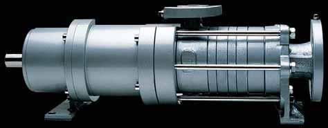
11 Corken s Industrial Magnetic Drive Vane Pump. Pressure Range: to 125 PSI* Temperature Range: -25 F to 225 F* Viscosity Range: Up to 75 SSU* Series CPMN Vane Pumps with Mag Drive GPM (@ 78 RPM)** MAGNETIC DRIVE VANE PUMP The magnetically driven vane pump eliminates mechanical seals to assure zero shaft leakage for your most critical pump sealing demands. It utilizes a magnetic coupling in which the magnetic force is transmitted from an outer motor-driven magnetic coupling through an isolation canister to an inner magnetic coupling mounted on the pump shaft. Magnetic Drive units provide synchronous rotation through the coupling. By using a Magnetic Drive Vane Pump, you can pump thin liquids with less maintenance and more confidence. The vane pump s maintenance-saving features include removable pump liners on all models, wear-resistant sleeve bushings instead of roller bearings, and reversible end plates. Porting flexibility including flanged ports with ANSI standards gives design flexibility. Without the need for mechanical shaft seals, the Magnetic Drive Vane pump is an excellent choice for pumping, hazardous, toxic, foul smelling, or other difficult to seal fluids. * Values shown represent minimums or maximums. Some special construction or consideration may be required before a catalogued pump can be applied to an application involving maximum pressure or minimum or maximum temperature and/or viscosity. ** Nominal capacities based on handling thin liquids at low pressures. Pushrods The Magnetic Drive Vane Pump utilizes larger diameter composite pushrods. Other vane pumps utilize steel pushrods which tend to drive in the vane and damage vanes and pump casings. Our pushrods protect from this problem, and that means less downtime and maintenance costs. End Plates The Magnetic Drive Vane Pump is designed with reversible end plates to double their service life. Casing Liner Removable casing liners are standard on all Magnetic Drive Vane Pumps. This allows the pump to be rebuilt without purchasing a new casing. That saves up to 75 percent of the cost of a new pump. If the casing liner wears out, it is quickly and easily replaced without disconnecting the plumbing to the pump. Magnetic Coupling The Magnetic Drive couples the pump to the driver. Magnetic force passing through a stainless steel canister is used to drive the inner coupling eliminating the need for shaft seals.

12 Magnetic Drive Vane pumps are available with various drive options including gear reducers on all models. The gear reducers are built for rugged operation yet are exceptionally quiet and compact. The pump is mounted on a formed steel base and includes guarded couplings between Magnetic Drive, reducer, and motor. CONSTRUCTION SERIES CPMN & CDMN (THREADED) AND SERIES CPMF (FLANGED) Pump Casing and Vane and Liner and Bearings Internal Relief Construction Heads Rotor Shaft Pushrods 1 End Plates O-rings 2 (2 Required) 3 Valve Spring CPMN Iron Ductile Iron Steel Composite Iron Buna-N Carbon Cadmium Graphite Plated Steel CPMF Ductile Iron Ductile Iron Steel Composite Iron Buna-N Carbon Graphite 4 CDMN Ductile Iron Ductile Iron Steel Composite Iron Buna-N SPECIFICATIONS SERIES CPMN (THREADED) AND SERIES CPMF (FLANGED) Carbon Graphite Cadmium Plated Steel Maximum Approximate Maximum Maximum Recommended Shipping Model Standard Port Nominal Differential Working Temperature for Weight Numbers Size (Inches) Pump Rating Pressure Pressure Catalogued Pump 5 Pounds Series Size Inlet 6-7 Outlet 6-7 GPM RPM PSI PISG Degrees F Unmounted CPMN CPMN CPMN CPMF CPMF CDMN CDMN Vanes are Ryton, pushrods are glass filled Teflon. 2 Buna-N O-rings are standard. Viton or Teflon available. 3 Carbon Graphite bearings are standard. Silicon Carbide bearings are available. 4 Internal relief valve not available in Series CPMF ductile iron construction. 5 Alternate magnet materials and/or special construction features are required at temperatures above 175 F. Consult factory for details. 6 Series CPMN has bolt-on flanges tapped for NPT pipe. Other sizes available; see dimensional drawings. 7 Series CPMF has port flanges suitable to use with 3# ANSI ductile iron or steel companion flanges or flanged fittings. Ryton is a trademark of Phillips Petroleum Company. Viton, Neoprene and Teflon are registered trademarks of the DuPont Company. FORM Corken, Inc. A Unit of IDEX Corporation P.O. Box 12338, Oklahoma City, OK U.S.A. 385 N.W. 36th St., Oklahoma City, OK Phone (45) Fax (45) Visit our website at us at corken@corken.com PRINTED IN THE U.S.A. FEBRUARY 21
13 Industrial Vane Pump Model Options 1 ALTERNATE DRIVE OPTIONS Hydraulic Motor Drive Integral Gear Reducer For the occasions when electric motor drives are not a preferred option, when misalignment has been an issue, or when space is limited, Corken introduces the CPH/CDH industrial vane line. These pumps allow for direct mounting of a hydraulic motor or gear reducer, forming a compact self aligned unit. On the CPH/CDH pump, we replace our standard drive side-bearing cap with an adapter that will mount to a 182/184 TC Nema bracket. As an option, we offer a Corken manufactured bracket that can be machined to accept an SAE A two bolt hydraulic motor or Viking B size gear reducer. Keep these pump models in mind for truck applications, as well as opportunities in which maintenance and installation experience is at a minimum. Feel free to contact your local Corken distributor for more information. 1-9
14 Industrial Vane Pump Model Selection 1 IS THE INDUSTRIAL VANE SERIES THE PUMP FOR YOUR APPLICATION? The following questions will allow you to determine if your application fits within the capabilities of the Corken Industrial Vane product line. If you are able to answer yes to all of the following questions, then proceed to the sizing worksheet below. If you must answer no to one or more of the questions, return to the Hydraulic Selection / Overview Graph to see if any of our other pump lines meet your basic conditions. Please feel free to call Corken or your local distributor with your questions. Is the viscosity of the liquid being pumped less than 1, SSU (22 CST)? Is the discharge pressure requirement less than 4 PSI (27.5 bar)? Will the temperature of the liquid being pumped remain between 25 F and 225 F? Is the liquid free of abrasives? Will iron pump casing be acceptable? SIZING WORKSHEET The next step in the sizing process is to ensure that you have all of the data that you need. We encourage you to make copies of this page and use it as a worksheet for selecting the proper Sliding Vane Model Pump. Liquid: Viscosity: (in SSU) See Page 5-3 to convert from Centipoise (cp) or Centistokes (cst) to SSU. Differential Pressure: psi If pressure is in feet of head, convert to psi with the following calculation: PSI = (ft. head x specific gravity of liquid) 2.31 Total Discharge Pressure: psi Desired Flow Rate: GPM SELECTION DATA You may use the blanks below to record the information that you obtain from the following sizing pages. Pump Series Speed Actual Flow Rate BHP Gear Reducer Part Number 1-11
15 1 Industrial Vane Pump Model Selection OVERVIEW OF PERFORMANCE RANGE PRESSURE DIFFERENTIAL CAPACITY MODEL NUMBER RANGE (PSI) RANGE (GPM) The table above provides a general overview of the performance range of each of our industrial vane models. Please note that only the models 521 through 121 are available in a magnetic drive configuration. Proceed to page 1-13 for detailed selection instructions. 1-12
16 Industrial Vane Pump Model Selection 1 INSTRUCTIONS FOR SELECTION OF VANE PUMP (ALL MODELS) 1. Turn to the page that corresponds with the model that you selected in the previous table on page Mechanical Seal Models Model Page 521 page 1-14 (Not available with ANSI flanged option) 721 page 1-15 (Not available in high pressure ductile iron design) 121 page page page 1-18 Magnetic Drive Models Model Page 521 page 1-19 (Not available with ANSI flanged option) 721 page 1-2 (Not available in high pressure ductile iron design) 121 page Once you have turned to the correct page, locate the graph with the viscosity value that most closely matches the viscosity of the liquid being pumped ( on the sizing worksheet). The viscosity corresponding to each graph is located in the lower right-hand corner of the graphs. Note: Corken industrial vane pumps can pump liquids with viscosities up to 1, SSU. Contact the factory for proper selection when your viscosity value exceeds 1, SSU. 3. Once you have located the proper graph, find the desired flow rate ( on sizing worksheet) on the lower portion of the vertical axis. 4. From that point, move horizontally to the right until you intersect the diagonal line that most closely corresponds to your differential pressure value ( on sizing worksheet). Note: The dashed portion of the performance curves relate to recommended intermittent duty operation as opposed to continuous duty. An example of intermittent duty is truck or tank car loading or unloading. 5. From this point, travel vertically down to the horizontal axis to determine the speed (in RPM) that the pump must turn to provide the desired capacity. If the viscosity of the liquid to be pumped exceeds 1 SSU, please read page 1-23 regarding pump speeds at higher viscosities. There are a few different methods that can be used to operate your vane pump at a specific speed. The most common methods are as follows: 1. Gear Reducer Drive 2. Variable Frequency Drive 3. V-Belt Drive The set of numbers on the horizontal axis labeled drive speeds represent the speeds available if a gear reducer drive is purchased from Corken. For more detail on the particular reducers available, see page Now its time to determine horsepower required. Move vertically up from the point on the horizontal axis that corresponds to the speed that you have decided to operate the vane pump. Continue until you reach the second set of curves towards the top of the graph. Stop when you reach the curve that most closely corresponds to the differential pressure of your application ( on sizing worksheet). 7. Move horizontally to the left until you reach the vertical axis. Record the horsepower value that corresponds to that point. This is the horsepower required by the pump. You must select a motor that is greater than this value. 8. Once you have logged the information taken from the graph, proceed to page 1-27 or 1-29 for model number selection. 1-13
17 1 Industrial Vane Pump Model Selection 521 SIZE PERFORMANCE DATA (MECHANICAL SEAL MODELS) MOTOR SIZES MOTOR SIZES HORSEPOWER INPUT BHP PSI 1 PSI 75 PSI 5 PSI 25 PSI HORSEPOWER INPUT BHP PSI 1 PSI 75 PSI 5 PSI 25 PSI 12 CAPACITY U.S. GPM PSI 75 PSI 125 PSI CAPACITY U.S. GPM PSI 75 PSI 125 PSI 2 VISC: 28 SSU 2 VISC: 38 SSU BASED ON 1 IN. HG. BASED ON 1 IN. HG DRIVE SPEEDS PUMP SPEED RPM SIZE DRIVE SPEEDS PUMP SPEED RPM SIZE 521 MOTOR SIZES MOTOR SIZES HORSEPOWER INPUT BHP PSI 1 PSI 75 PSI 5 PSI 25 PSI HORSEPOWER INPUT BHP PSI 1 PSI 75 PSI 5 PSI 25 PSI PSI 125 PSI 1 CAPACITY U.S. GPM CAPACITY U.S. GPM PSI 125 PSI 2 VISC: 1 SSU 2 VISC: 75 SSU BASED ON 1 IN. HG. BASED ON 1 IN. HG DRIVE SPEEDS PUMP SPEED RPM SIZE DRIVE SPEEDS PUMP SPEED RPM SIZE


18 Industrial Vane Pump Model Selection SIZE PERFORMANCE DATA (MECHANICAL SEAL MODELS) 1-15
19 1 Industrial Vane Pump Model Selection 121 SIZE PERFORMANCE DATA (MECHANICAL SEAL MODELS) MOTOR SIZES MOTOR SIZES HORSEPOWER INPUT BHP PSI 1 PSI 75 PSI 5 PSI 25 PSI HORSEPOWER INPUT BHP PSI 1 PSI 75 PSI 5 PSI 25 PSI CAPACITY U.S. GPM PSI 75 PSI 125 PSI CAPACITY U.S. GPM PSI 125 PSI 5 VISC: 28 SSU 5 VISC: 38 SSU BASED ON 1 IN. HG. BASED ON 1 IN. HG DRIVE SPEEDS PUMP SPEED RPM SIZE 121 DRIVE SPEEDS SIZE PUMP SPEED RPM MOTOR SIZES MOTOR SIZES HORSEPOWER INPUT BHP PSI 1 PSI 75 PSI 5 PSI 25 PSI HORSEPOWER INPUT BHP PSI 1 PSI 75 PSI 5 PSI 25 PSI 25 CAPACITY U.S. GPM PSI 125 PSI CAPACITY U.S. GPM PSI 125 PSI 5 VISC: 1 SSU 5 VISC: 75 SSU BASED ON 1 IN. HG. BASED ON 1 IN. HG. DRIVE SPEEDS SIZE PUMP SPEED RPM DRIVE SPEEDS SIZE PUMP SPEED RPM 1-16
20 Industrial Vane Pump Model Selection SIZE PERFORMANCE DATA (MECHANICAL SEAL MODELS) 1-17
21 1 Industrial Vane Pump Model Selection 1521 SIZE PERFORMANCE DATA (MECHANICAL SEAL MODELS) MOTOR SIZES MOTOR SIZES 4 4 HORSEPOWER INPUT BHP PSI 75 PSI 5 PSI 25 PSI HORSEPOWER INPUT BHP PSI 75 PSI 5 PSI 25 PSI 5 CAPACITY U.S. GPM PSI 5 PSI 1 PSI CAPACITY U.S. GPM PSI 1 PSI 1 VISC: 28 SSU 1 VISC: 38 SSU BASED ON 1 IN. HG. BASED ON 1 IN. HG. DRIVE SPEEDS SIZE PUMP SPEED RPM DRIVE SPEEDS SIZE PUMP SPEED RPM MOTOR SIZES MOTOR SIZES HORSEPOWER INPUT BHP PSI 75 PSI 5 PSI 25 PSI HORSEPOWER INPUT BHP PSI 75 PSI 5 PSI 25 PSI 5 5 CAPACITY U.S. GPM PSI 1 PSI CAPACITY U.S. GPM PSI 1 PSI 1 VISC: 1 SSU 1 VISC: 75 SSU BASED ON 1 IN. HG. BASED ON 1 IN. HG. DRIVE SPEEDS SIZE PUMP SPEED RPM DRIVE SPEEDS SIZE PUMP SPEED RPM 1-18
22 Industrial Vane Pump Model Selection 1 SERIES CPMN AND CDMN 521 SIZE PERFORMANCE DATA (MAGNETIC DRIVE MODELS) 1-19
23 1 Industrial Vane Pump Model Selection SERIES CPMN AND CPMF 721 SIZE PERFORMANCE DATA (MAGNETIC DRIVE MODELS) MOTOR SIZES MOTOR SIZES HORSEPOWER INPUT BHP PSI 75 PSI 5 PSI 25 PSI HORSEPOWER INPUT BHP PSI 75 PSI 5 PSI 25 PSI CAPACITY U.S. GPM PSI 75 PSI 1 PSI CAPACITY U.S. GPM PSI 75 PSI 1 PSI 25 VISC: 28 SSU 25 VISC: 38 SSU BASED ON 1 IN. HG. BASED ON 1 IN. HG. DRIVE SPEEDS SIZE PUMP SPEED RPM DRIVE SPEEDS SIZE PUMP SPEED RPM MOTOR SIZES MOTOR SIZES HORSEPOWER INPUT BHP PSI 75 PSI 5 PSI 25 PSI HORSEPOWER INPUT BHP PSI 75 PSI 5 PSI 25 PSI PSI 1 PSI PSI 1 PSI CAPACITY U.S. GPM CAPACITY U.S. GPM VISC: 1 SSU 25 VISC: 75 SSU BASED ON 1 IN. HG. BASED ON 1 IN. HG. DRIVE SPEEDS SIZE PUMP SPEED RPM DRIVE SPEEDS SIZE PUMP SPEED RPM 1-2
24 Industrial Vane Pump Model Selection 1 SERIES CPMN, CDMN AND CPMF 121 SIZE PERFORMANCE DATA (MAGNETIC DRIVE MODELS) 1-21
25 Industrial Vane Pump Model Selection 1 VISCOSITY GUIDELINES The graph below provides recommendations for maximum pump speed when operating at elevated viscosities. Use this as a guideline when determining the pump speed for your application. Currently our published performance curves stop at just under 1 SSU. For applications in which the liquid exceeds this viscosity, please contact your local distributor or call our factory Maximum Pump Speed (RPM) (SSU) (Centistokes) VISCOSITY 1-23
26 Industrial Vane Pump Model Selection 1 GEAR REDUCER SELECTION For Corken supplied direct drive mountings, Viking gear reducers are the standard. Below we have provided tables to aid in the selection of the proper gear reducer size and ratio. Selection Procedure: 1. To select the correct reducer, start with the B size table. 2. Locate the row that corresponds with the motor speed that will be utilized. 3. Move to the right until you locate the pump speed that is needed to produce desired flow rate. 4. Look at the HP value directly below the speed that you selected. If this value is greater than the HP required by the pump you selected proceed to the next step. If it is less than the pump s required HP, move to the C size reducer table and repeat steps 2 through Move to the top of the column and note the reducer size, ratio and Corken part number on your sizing worksheet. You will use this information in the pricing and ordering process. High Speed Shaft Input RPM Gear Reducer Ratios B Size 1.87:1 2.24:1 2.76:1 3.4:1 4.19:1 5.6:1 6.27:1 7.65:1 Corken Part Number Low Speed Shaft RPM Maximum Reducer HP Low Speed Shaft RPM Maximum Reducer HP Low Speed Shaft RPM Maximum Reducer HP High Speed Shaft Input RPM Gear Reducer Ratios C Size 2.21:1 2.8:1 3.31:1 4.21:1 5.8:1 6.24:1 7.95:1 Corken Part Number Low Speed Shaft RPM Maximum Reducer HP Low Speed Shaft RPM Maximum Reducer HP Low Speed Shaft RPM Maximum Reducer Hp 1-25
27 Industrial Vane Pump Model Selection 1 MODEL NUMBER SELECTION GUIDE (MECHANICAL SEALED MODELS) CD B N 521 H G E 3 E E Pressure Capabilities Options: CP- 2 psig working pressure capability CD-4 psig working pressure capability Design Type Options: B- Stationary Vane Pump H- Hydraulic Drive / Integral Gear Vane Pump Flange Type Options: F- 3 lb. ANSI flanges / no internal relief valve N- NPT threaded flanges / internal relief valve Pump Size Sliding Vane Pump with Single or Double Shaft Options: 521/ GPM 721/ GPM 121/ GPM 1321/ GPM 1521/ GPM Note: Those Models Ending in a 2 (i.e. 122) Have Double Extended Shafts Blade Quantity 6 Blades, with Blade Drivers Blade Material GCB-5 Blades with Composite Push Rods O-ring Material Options: A- Buna-N B- Neoprene* D- Viton* E- PTFE G- Ethylene-Propylene L- Buna-N with Viton* Seal O-rings M- Buna-N with PTFE Seal O-rings N- Viton* with PTFE Seal O-ring Sealing Material Options: 1- Stainless Steel Seal Seat 3- Ni-Resist Seal Seat (Standard) 9 Inlet Flange E- 2 NPT Flange F- 2 Slip-on Weld Flange J- 2-1/2 NPT Flange K- 2-1/2 Slip-on Weld Flange L- 2-1/2 3 lb. ANSI Flange M- 3 NPT Flange N- 3 Slip-on Weld Flange P- 3 3 lb. ANSI Flange Q- 4 NPT Flange R- 4 Slip-on Weld Flange S- 4 3 lb. ANSI Flange Outlet Flange C- 1-1/2 NPT Flange D- 1-1/2 Slip-on Weld Flange E- 2 NPT Flange F- 2 Slip-on Weld Flange H- 2 3 lb. ANSI Flange J- 2-1/2 NPT Flange K- 2-1/2 Slip-on Weld Flange L- 2-1/2 3 lb. ANSI Flange M- 3 NPT Flange N- 3 Slip-on Weld Flange P- 3 3 lb. ANSI Flange Q- 4 NPT Flange R- 4 Slip-on Weld Flange Note: Not all flange options are available for all pump sizes. See back side of this page for acceptable options
28 1 Industrial Vane Pump Model Selection MODEL NUMBER SELECTION GUIDE CP MODELS Inlet Flange Standard 2 NPT E 2 1 /2 NPT J 3 NPT M 3 ANSI P 4 NPT Q 4 ANSI S No Cost 2 1 /2 NPT J 3 NPT M Extra Cost 2 WF F 2 1 /2 WF K 3 WF N 4 WF R Outlet Flange Standard 2 NPT E 2 1 /2 NPT J 2 ANSI H 2 1 /2 ANSI G 3 NPT M 3 ANSI P 4 NPT Q No Cost 1 1 /2 NPT C 2 NPT E 2 1 /2 NPT J 3 NPT M 4 NPT Q Extra Cost 1 1 /2 WF D 2 WF F 2 1 /2 WF K 3 WF N 4 WF R CD MODELS Inlet Flange Standard 2 NPT E 2 1 /2 NPT J 3 NPT M 3 ANSI P 4 NPT Q 4 ANSI S 2 1 /2 ANSI L No Cost 2 1 /2 NPT J 3 NPT M 4" NPT Q Extra Cost 2 WF F 2 1 /2 WF K 3 WF N 4 WF R Outlet Flange Standard 2 NPT E 2 1 /2 NPT J 2 ANSI H 2 1 /2 ANSI G 3 NPT M 3 ANSI P 4 NPT Q No Cost 1 1 /2 NPT C 2 NPT E 2 1 /2 NPT J 3 NPT M 4 NPT Q Extra Cost 1 1 /2 WF D 2 WF F 2 1 /2 WF K 3 WF N 4 WF R 1-28
29 Industrial Vane Pump Model Selection 1 MODEL NUMBER SELECTION GUIDE (MAGNETIC DRIVE MODELS) CP M N 121 H G D A M M Pressure Capabilities Options: CP- 2 psig working pressure capability CD-4 psig working pressure capability Design Type Magnetic Drive Vane Pump Flange Type Options: F- 3 lb. ANSI flanges / no internal relief valve N- NPT threaded flanges / internal relief valve Pump Size Options: GPM GPM GPM Blade Quantity 6 Blade with Blade Drivers Blade Material GCB-5 Blades with Composite Push Rods O-ring Material A- Buna-N B- Neoprene* D- Viton* E- PTFE G- Ethylene-Propylene Magnet and Sleeve Bearing Material A- Neodymium Magnets and Carbon Graphite Sleeve Bearings B- Neodymium Magnets and Silicon Carbide Sleeve Bearings C- Samarium Magnets and Carbon Graphite Sleeve Bearings D- Samarium Magnets and Silicon Carbide Sleeve Bearings 9 Inlet Flange E- 2 NPT Flange F- 2 Slip-on Weld Flange J- 2-1/2 NPT Flange K- 2-1/2 Slip-on Weld Flange M- 3 NPT Flange N- 3 Slip-on Weld Flange P- 3 3 lb. ANSI Flange Q- 4 NPT Flange R- 4 Slip-on Weld Flange S- 4 3 lb. ANSI Flange Outlet Flange C- 1-1/2 NPT Flange D- 1-1/2 Slip-on Weld Flange E- 2 NPT Flange F- 2 Slip-on Weld Flange H- 2 3 lb. ANSI Flange J- 2-1/2 NPT Flange K- 2-1/2 Slip-on Weld Flange L- 2-1/2 3 lb. ANSI Flange M- 3 NPT Flange N- 3 Slip-on Weld Flange P- 3 3 lb. ANSI Flange Q- 4 NPT Flange R- 4 Slip-on Weld Flange Note: Not all flange options are available for all pump sizes. See back side of this page for acceptable options
30 1 Industrial Vane Pump Model Selection MODEL NUMBER SELECTION GUIDE CP MODELS Inlet Flange Standard 2 NPT E 2 1 /2 NPT J 3 NPT M 3 ANSI P 4 NPT Q 4 ANSI S No Cost 2 1 /2 NPT J 3 NPT M Extra Cost 2 WF F 2 1 /2 WF K 3 WF N 4 WF R Outlet Flange Standard 2 NPT E 2 1 /2 NPT J 2 ANSI H 2 1 /2 ANSI G 3 NPT M 3 ANSI P 4 NPT Q No Cost 1 1 /2 NPT C 2 NPT E 2 1 /2 NPT J 3 NPT M 4 NPT Q Extra Cost 1 1 /2 WF D 2 WF F 2 1 /2 WF K 3 WF N 4 WF R CD MODELS Inlet Flange Standard 2 NPT E 2 1 /2 NPT J 3 NPT M 3 ANSI P 4 NPT Q 4 ANSI S 2 1 /2 ANSI L No Cost 2 1 /2 NPT J 3 NPT M 4" NPT Q Extra Cost 2 WF F 2 1 /2 WF K 3 WF N 4 WF R Outlet Flange Standard 2 NPT E 2 1 /2 NPT J 2 ANSI H 2 1 /2 ANSI G 3 NPT M 3 ANSI P 4 NPT Q No Cost 1 1 /2 NPT C 2 NPT E 2 1 /2 NPT J 3 NPT M 4 NPT Q Extra Cost 1 1 /2 WF D 2 WF F 2 1 /2 WF K 3 WF N 4 WF R 1-3
 OPT: 2-1/2 NPT OPT: 2-1/2 NPT 157 157 127 51 35 12 119 2 149 187 95 229 3 NPT 1-1/2 NPT CPBN721 STD: 2-1/2 NPT STD: 2-1/2 NPT 5.62 1.16 5.75 4.56.81 2. 1.5 3.38 4.56 8.69 6.69 1.19 4.5 8.")
31 Industrial Vane Pump Data / Dimensions 1 CPBN/CDBN MODEL A INLET B OUTLET C C1* D D1 D2* E F G H J K L M N CPBN521 STD: 2 NPT STD: 2 NPT (In/mm) OPT: 2-1/2 NPT OPT: 2-1/2 NPT NPT 1-1/2 NPT CPBN721 STD: 2-1/2 NPT STD: 2-1/2 NPT OPT: 3 NPT OPT: 2 NPT & 3 NPT CPBN121 STD: 3 NPT STD: 3 NPT OPT: 2-1/2 NPT OPT: 2 NPT /2 NPT CPBN 1321 STD: 4 NPT STD: 3 NPT OPT: 4 NPT CPBN1521 STD: 4 NPT STD: 4 NPT OPT: 3 NPT CDBN521 STD: 2 NPT STD: 2 NPT OPT: 2-1/2 NPT OPT: 2-1/2 NPT & 1-1/2 NPT CDBN121 STD: 3 NPT STD: 3 NPT OPT: 4 NPT OPT: 4 NPT CDBN1321 STD: 4 NPT STD: 3 NPT OPT: 4 NPT CDBN1521 STD: 4 NPT STD: 4 NPT OPT: 3 NPT *NOTE: For some models C1 and D2 will be. This denotes that the suction and/or discharge flange will be centered with the shaft. 1-31
32 1 Industrial Vane Pump Data / Dimensions CPBF/CDBF MODEL A INLET B OUTLET C D E F G J K L M CPBF # ANSI 2 3# ANSI CPBF # ANSI 2-1/2 3# ANSI CPBF # ANSI 3 3# ANSI CPBF # ANSI 3 3# ANSI CDBF # ANSI 2-1/2 3# ANSI CDBF # ANSI 3 3# ANSI CDBF # ANSI 3 3# ANSI

33 Industrial Vane Pump Data / Dimensions 1 CPHN/CDHN Note: Bare pump includes 182 / 184 TC Mounting Flange. Bracket shown above (shaded area) is sold separately. MODEL A INLET B OUTLET C C1* D D1 D2* E F G H J K L M N CPHN521 STD: 2 NPT STD: 2 NPT OPT: 2-1/2 NPT OPT: 2-1/2 NPT NPT 1-1/2 NPT CPHN721 STD: 2-1/2 NPT STD: 2-1/2 NPT OPT: 3 NPT OPT: 2 NPT CPHN121 STD: 3 NPT STD: 3 NPT OPT: 2-1/2 NPT OPT: 2-1/2 NPT NPT CPHN 1321 STD: 4 NPT STD: 3 NPT OPT: 4 NPT CPHN1521 STD: 4 NPT STD: 4 NPT OPT: 3 NPT CDHN521 STD: 2 NPT STD: 2 NPT OPT: 2-1/2 NPT OPT: 2-1/2 NPT /2 NPT CDHN121 STD: 3 NPT STD: 3 NPT OPT: 4 NPT OPT: 4 NPT CDHN1521 STD: 4 NPT STD: 4 NPT OPT: 3 NPT *NOTE: For some models C1 and D2 will be. This denotes that the suction and/or discharge flange will be centered with the shaft. 1-33
34 1 Industrial Vane Pump Data / Dimensions INTEGRAL GEAR OPTION C D K E G F F G H J I MODEL A INLET B OUTLET C D E F G H I J K CPHN521 STD: 2 NPT STD: 2 NPT OPT: 2-1/2 NPT OPT: 2-1/2 NPT NPT 1-1/2 NPT CPHN721 STD: 2-1/2 NPT STD: 2-1/2 NPT OPT: 3 NPT OPT: 2 NPT CPHN121 STD: 3 NPT STD: 3 NPT OPT: 2-1/2 NPT OPT: 2-1/2 NPT NPT CPHN1321 STD: 4 NPT STD: 3 NPT OPT: 4 NPT CPHN1521 STD: 4 NPT STD: 3 NPT OPT: 3 NPT CPHF721 STD: 3 3# STD: 2 3# CPHF121 STD: 3 3# STD: 2-1/2 3# CPHF1521 STD: 4 3# STD: 3 3# CPHF1321 STD: 4 3# STD: 3 3# CDHN521 STD: 2 NPT STD: 2 NPT OPT: 2-1/2 NPT OPT: 2-1/2 NPT /2 NPT CDHN121 STD: 3 NPT STD: 3 NPT OPT: 4 NPT OPT: 4 NPT CDHN1521 STD: 4 NPT STD: 4 NPT OPT: 3 NPT

35 Industrial Vane Pump Data / Dimensions 1 CPMN/CDMN MODEL A INLET B OUTLET C C1 D D1 D2 F G H K L M N S T V W X CPMN521 STD: 2 NPT STD: 2 NPT * OPT: 2-1/2 NPT OPT: 2-1/2 NPT NPT 1-1/2 NPT CPMN721 STD: 2-1/2 NPT STD: 2-1/2 NPT * OPT: 3 NPT OPT: 2 NPT NPT CPMN121 STD: 3 NPT STD: 3 NPT OPT: 2-1/2 NPT OPT: 2-1/2 NPT NPT CDMN521 STD: 2 NPT STD: 2 NPT * OPT: 2-1/2 NPT OPT: 1-1/2 NPT /2 NPT CDMN121 STD: 3 NPT STD: 3 NPT OPT: 4 NPT OPT: 4 NPT * Pump must be blocked up to match 5.5 center height of bearing carrier. 1-35
36 1 Industrial Vane Pump Data / Dimensions CPMF OUTLET "B" INLET "A" M 4.5 (12.7) DIA. HOLES MODEL A INLET B OUTLET C D F G K L M S T V W X CPMF * LB ANSI 3 LB ANSI CPMF / LB ANSI 3 LB ANSI * Pump must be blocked up to match 5.5 center height of bearing carrier. 1-36


37 PZ-Series Coro-Vane Petroleum Pumps For refined petroleum products and industrial solvents


38 A choice in petroleum pumps Multi-product package offering Viton 1 O-rings standard on PZ-Series pumps... extend pump life. for extended life. replacements required. Controlling thrust loads and cavitation are critical for extended pump life... and vane drivers. 1 Viton is a registered trademark of the DuPont company. 2


 Pump Accessories")
39 Why this pump lasts longer, needs service less often... PZ-Series Coro-Vane Maintenance made simple... Two bypass options are available... The standard bypass valve The Air Operated Valve (AOV) Pump Accessories Strainer Air operated valve (AOV) 3
 Up to 3 F (149 C) 2 psi (13.")
40 Specifications Operating Specifications Standard connections: Optional connections: Maximum differential pressure: Temperature range: Maximum working pressure: Maximum speed: Fluids handled: PZ7 and PZ1 2 or 2-1/2 NPT 2 or 2-1/2 BSPT, Slip-on Weld 125 psid (8.6 bar) Up to 3 F (149 C) 2 psi (13.8 bar) 8 RPM Re ned petroleum products and industrial solvents Material Specifications Part Model Material Case All Ductile iron ASTM A536 Head All Ductile iron ASTM A536 Flanges All Ductile iron ASTM A536 Rotor All Ductile iron ASTM A536 Bearing cap All Ductile iron ASTM A536 Sideplates All Cast iron Class 3 Vanes & vane drivers All Advanced polymer Cast iron ASTM A48 electroless PZ7 Bypass valve nickel plated PZ PH Stainless steel Bypass valve spring All Steel Seal seat All Cast iron Seal metal parts All Steel Shaft All 862 steel Thrust bearing All Steel O-rings All Viton 1 (standard), Buna-N (optional) 1 Viton is a registered trademark of the DuPont company. PZ7 Performance Chart Pump Speed Differential Pressure Nominal Flowrate 2 Brake Hp Required Torque Required RPM psi bar gpm L/min bhp kw in lbs N m PZ1 Performance Chart Pump Speed Differential Pressure Nominal Flowrate 2 Brake Hp Required Torque Required RPM psi bar gpm L/min bhp kw in lbs N m Nominal flow rate at pump outlet. The actual flow rate from the hose nozzle will be less, depending on hose length, hose diameter, nozzle size, product viscosity, and other system flow restrictions. Approximate capacities and horsepowers are based on a 38 SSU (3 cp) fluid. PZ1C PRINTED IN THE USA MARCH 211

41 INDPZP1B PZ-Series Petroleum Pumps Sales Catalog PZ7 Model with Standard Bypass Valve
42 PZ-Series Petroleum Pumps A Unit of IDEX Corporation Technical Specifications Features & Benefits... 3 Operating and Material Specifications... 3 Performance Curves... 4 Model Number Indentification Code for the PZ7 and PZ Model Number Indentification Code for the Strainer and Air Operated Valve (AOV)... 7 Outline Dimensions for the PZ Outline Dimensions for the PZ Outline Dimensions for the Air Operated Valve (AOV) and Strainer
43 A Unit of IDEX Corporation PZ-Series Petroleum Pumps Technical Specifications Equipment Type & Options Foot mounted, sliding vane, positive displacement petroleum pump. Applications Designed for applications that involve refined petroleum products and industrial solvents. Features & Benefits Nonmetallic vanes: Nonmetallic vane drivers: Thrust bearing: Sideplates: Easy maintenance: Dual ended shaft: New design and advanced material provides longer life than most vanes. Vanes self adjust for wear and maintain internal pump clearances for sustained performance. Corken vane drivers are made of a extremely durable, lightweight, advanced material which is less destructive to the vanes than other conventional steel push rods. Handles heavy thrust loads from PTO without difficult adjustments. Precision machined sideplates are reversible for extended life. Vanes can be easily replaced without removing the pump from the piping. Pump can easily adapt to either right- or left-hand PTO rotation. Two bypass options: Manually adjustable internal bypass valve or optional Air Operated Valve (AOV) for high and low flow control. Operating Specifications Standard connections: Optional connections: Maximum differential pressure: Operating temperature range: Maximum working pressure: Maximum speed: Fluids: 2" or 2-1/2" NPT 2" or 2-1/2" Slip-on weld, BSPT 125 psid (8.6 bar) Up to 3 F (149 C) 2 psi (13.8 bar) 8 RPM For refined petroleum products and industrial solvents Material Specifications Part Model Material Case All Ductile iron ASTM A536 Head All Ductile iron ASTM A536 Flanges All Ductile iron ASTM A536 Rotor All Ductile iron ASTM A536 Bearing cap All Ductile iron ASTM A536 Sideplates All Cast iron Class 3 Vanes & vane drivers All Advanced polymer Bypass valve All 17-4 PH Stainless steel Bypass spring All Steel Seal seat All Cast iron (standard), Stainless steel and Ni-Resist (optional) Seal metal parts All Steel Shaft All 862 steel Thrust bearing All Steel O-rings All Viton 1 (standard), Buna-N (optional) 1 Viton is a registered trademark of the Dupont Company 3
44 A Unit of IDEX Corporation PZ-Series Petroleum Pumps Performance Curves 1 PZ7 Petroleum Pump RPM Capacity (gpm) RPM 64 RPM 6 42 RPM Differential Pressure (psi) Pump Speed Differential Pressure Nominal Flowrate Brake HP Required Torque Required RPM psi bar gpm L/min bhp kw in lbs N m These curves depict performance of the PUMP ONLY. Performance will vary in applications due to system design and variables. Approximate capacities and horsepowers are based on 38 SSU (3 cp) fluid. 4
45 A Unit of IDEX Corporation PZ-Series Petroleum Pumps Performance Curves 1 PZ1 Petroleum Pump RPM Capacity (gpm) RPM 64 RPM RPM Differential Pressure (psi) Pump Speed Differential Pressure Nominal Flowrate Brake HP Required Torque Required RPM psi bar gpm L/min bhp kw in lbs N m These curves depict performance of the PUMP ONLY. Performance will vary in applications due to system design and variables. Approximate capacities and horsepowers are based on 38 SSU (3 cp) fluid. 5
46 A Unit of IDEX Corporation PZ-Series Petroleum Pumps Model Number Identification Code for PZ-Series Model Number Base X X X X X X X Base Model Basic pump Model PZ7 or PZ1 Standard PZ7 Specification Fields Strainer 1 No strainer Standard N Strainer Optional S Internal bypass Standard valve Standard S valve Air Operated Valve Optional A Low (5 75 psi) Optional 1 Bypass valve spring Std. (75 1 psi) Standard 2 High (1 125 psi) Optional 3 Seal O-ring Viton 2 Standard D material Buna-N Optional A Stainless steel Optional 1 Seal seat material Cast iron Standard 2 Ni-Resist Optional 3 1 Strainer is attached to the pump when specified by suffix S in the configurated string. When the strainer is required separate from the pump, order using the Part Number found in the Strainer Assembly table on page 7. 2 Viton is a registered trademark of the Dupont company. Inlet Flange Options Standard Optional Outlet Flange Options Standard Optional 2" NPT E 2-1/2" NPT J 2" BSPT M 2-1/2" BSPT N 2" Weld F 2-1/2" Weld K 2" NPT E 2-1/2" NPT J 2" BSPT M 2-1/2" BSPT N 2" Weld F 2-1/2" Weld K 6
47 A Unit of IDEX Corporation PZ-Series Petroleum Pumps Model Number Identification Code for Strainer and Air Operated Valve (AOV) Strainer Assembly 1 for PZ7 and PZ1 Strainer Assembly Seal Material Viton 2 (standard) Buna-N (optional) 1 Strainer Assembly ordered by Part Number when not assembled to the pump. 2 Viton is a registered trademark of the Dupont company. Strainer Assy. Part Number 5422-XD 5422-XA Air Operated Valve Assembly (AOV) For Pump Models AOV Part Number Air Operated Valve PZ7 547-X (AOV) PZ X 7
48 A Unit of IDEX Corporation PZ-Series Petroleum Pumps Outline Dimensions for the PZ7 PZ7 with Standard Bypass Valve Inches (centimeters) PZ7 with Standard Bypass Valve PZ7 with Air Operated Valve (AOV) Inches (centimeters) 8
49 A Unit of IDEX Corporation PZ-Series Petroleum Pumps Outline Dimensions for the PZ1 PZ1 with Standard Bypass Valve Inches (centimeters) PZ1 with Standard Bypass Valve PZ1 with Air Operated Valve (AOV) Inches (centimeters) 9
50 A Unit of IDEX Corporation PZ-Series Petroleum Pumps Outline Dimensions for Air Operated Valve and Strainer 547-X Air Operated Valve (AOV) for the PZ7 Pump 3.25 (8.26) 4.25 (1.79) 3.25 (8.26) Inches (centimeters) 3.25 (8.26) 5462-X Air Operated Valve (AOV) for the PZ1 Pump 3.75 (9.52) 4.48 (11.3) 3.75 (9.52) Inches (centimeters) 3.75 (9.52) 5422-X_ Strainer Assembly for the PZ7 and PZ1 Pump Inches (centimeters) 1
51
52 Corken, Inc. A Unit of IDEX Corporation 385 N.W. 36th St., Oklahoma City, OK Phone (45) Fax (45) Visit our website at us at info.corken@idexcorp.com Printed in the U.S.A. April 24


53 Petroleum Pumps PT-Series Pumps for Refined Petroleum Products and Industrial Solvents LIQUID CONTROLS GROUP


54 Another choice in petroleum pumps... The Liquid Controls Group PT-Series petroleum pumps offer the industry another choice in pump brand when building bulk plant and delivery vehicle systems. The pumps match the industry-standard flange-to-flange and mounting foot print dimensions for easy incorporation into existing or new bulk plant and delivery vehicle systems. The features of the PT-Series will be appreciated by bulk plant designers, delivery truck fabricators and end-user fuel marketers. Multi-product package offering... When it comes to ease of doing business, product functionality, and breadth of product offering, Liquid Controls Group is your single source solution for transporting, dispensing and controlling high value fluids and gases. Common corporate ownership and shared distribution enables Liquid Controls Group to greatly simplify the procurement process. Rather than placing multiple orders, a customer can combine a pump, meter, and register into a single order. Three pump sizes available... Available in 2, 2.5 and 3 inch flange sizes. Flow rates range from 31 to 271 gpm (117 to 1,26 L/min) and differential pressures up to 125 psi (8.6 bar) Features of the PT-Series O-ring design delivers maximum sealing capability and is available with optional seal materials. Corrosion resistant bypass valve made of nickel plated cast iron. Available with a standard bypass valve or an optional air operated valve (AOV) for high and low flow control. Additionally, the AOV relieves the pressure in the lines for easier handling of the hose nozzle. Reliable mechanical seal design with optional seal materials. Heavy duty ball bearings provide greater durability and strength. Hollow rotor helps reduce weight. Available with T-style strainers that help keep your pumping system free from damage caused by welding slag and foreign materials left in the piping and tank. Conveniently located drain plug allows you to empty the pump quickly when necessary. Positive displacement sliding vane design delivers higher pumping efficiency and a lower noise level. The self adjusting vanes compensate for wear and extend the life of the pump. Installation is simple since the PT-Series pumps are dimensionally interchangeable with the competition. Viton 1 elastomers ensure compatibility with a wider range of fluids such as biodiesel and ethanol blends. 4 1 Viton is a registered trademark of the DuPont company. 5 6 Pump Accessories 7 Optional Air Operated Valve (AOV) 8 Model PT3 9 2 Optional T-style Strainer


55 Liquid Controls Group offers a wide range of products for transporting, dispensing, and controlling high value fluids and gases. These products include the following: Pumps Meters Valves Registers Electronics In cab data management systems Inventory control systems Applications Include Fuel oil deliveries Fleet refueling Lube oil deliveries Aviation refuelers Bulk transfer Bulk loading & blending Model PT2 The model PT2 is a 2 inch petroleum pump and is ideal for lube oil deliveries that require low flow rates. Applications include deliveries to service centers such as auto dealerships and quick lube companies. Transporting the following: Petro chemicals Gasoline Biofuels Ethanol Solvents Model PT2 Model PT25 The model PT25 is a 2.5 inch petroleum pump and is suited for delivery trucks that transport gasoline, diesel, fuel oil and other petroleum products. The flow rates are perfect for home, farm and fleet fueling applications. Model PT25 Model PT3 The model PT3 is a 3 inch petroleum pump and is ideal for bulk delivery applications such as large transport tanks. The PT3 is designed to quickly load and unload large volumes. Bulk deliveries include aviation fuels, gasoline, diesel, ethanol, biodiesel and many more. Model PT3 3
 125 (8.6) 2 (13.8) 3 (149) PT25 159 (62) 78 2, (4,25) 125 (8.6) 2 (13.8) 3 (149) PT3 271 (1,26) 64 2, (4,25) 125 (8.6) 2 (13.8) 3 (149) Performance Data 1 RPM 52 64 52 64 52 64 GPM (L/min) 58 (22) 72 (273) 98 (371) 12 (454) 211 (799) 263 (995) HP (kw) 2.")
 manual for flow rates at other pressures.")
56 Maximum Specifications Chart Differential Pressure Model PT2 PT25 PT3 Working Pressure Model Flow Pump Speed Viscosity Temperature GPM (L/min) RPM SSU (cp) psi (bar) psi (bar) F ( C) PT2 88 (333) 78 2, (4,25) 125 (8.6) 2 (13.8) 3 (149) PT (62) 78 2, (4,25) 125 (8.6) 2 (13.8) 3 (149) PT3 271 (1,26) 64 2, (4,25) 125 (8.6) 2 (13.8) 3 (149) Performance Data 1 RPM GPM (L/min) 58 (22) 72 (273) 98 (371) 12 (454) 211 (799) 263 (995) HP (kw) 2.5 (1.9) 3. (2.2) 3.8 (2.8) 5. (3.7) 7.8 (5.8) 9.5 (7.1) 1 Capacities and horsepower are based on a 1 SSU (22 cp) fluid at 5 psi (3.4 bar) delivered pressure. Refer to performance curves in the PT-Series sales catalog or the installation, operation and maintenance (IOM) manual for flow rates at other pressures. Outline Dimensions (all dimensions in inches and centimeters) Model A B C D E F G H I J K L PT2 PT25 PT Dia. (2.86) Dia. (2.86) Dia. (2.86) 5.18 (13.16) 6.64 (16.87) 6.93 (17.6) 4. (1.16) 4. (1.15) 5.38 (13.7) 3.63 (9.22) 3.63 (9.22) 4.25 (1.8).81 (2.6) 1.5 (3.81) 1.25 (3.2).81 (2.6) 1.5 (3.81) 1.25 (3.2) 1.75 (4.45) 2.45 (6.21) 2.19 (5.6) 1.75 (4.45) 2.45 (6.21) 2.19 (5.6) 8. (2.32) 9.45 (23.99) 9.63 (24.4) 8. (2.32) 8.75 (22.23) 9.63 (24.4) 6.8 (15.44) 6.8 (17.27) 8.6 (21.8) 1.5 (3.81) 1.75 (4.45) 2.5 (6.4) Model M N O P Q R S T U V W PT2 PT25 PT (12.66) 6.35 (16.12) 6.44 (16.4) 4.13 (1.48) 5.6 (12.86) 5.31 (13.5).5 (1.27).25 (.64).75 (1.9).44 Dia. (1.12).44 Dia. (1.12).63 Dia. (1.58) 2.5 (6.35) 2.75 (6.99) 3. (7.6) 2.5 (6.35) 2.75 (6.99) 3. (7.6) 3.31 (8.4) 3.5 (8.89) 3.63 (9.2) 3.31 (8.4) 3.5 (8.89) 3.63 (9.2) 3.9 (9.92) 4.31 (1.95) 5. (12.7) 3.9 (9.92) 3.87 (9.87) 4.95 (12.6) W K L 5.3 (13.46) 6.5 (15.36) 6.43 (16.33) B N M A C O P (4 holes) D I E G H F J U S Q R T V Corken Liquid Controls Liquid Controls Europe Liquid Controls India Liquid Controls Sponsler SAMPI Toptech Systems CORKEN, INC. 385 N.W. 36th St., Oklahoma City, OK P1B LIQUID CONTROLS 15 Albrecht Drive, Lake Bluff, IL PRINTED IN THE USA NOVEMBER 29


57 INDP1C Petroleum Pumps Sales Catalog for PT-Series Model PT2 Model PT25 with optional air operated valve (AOV) and strainer Model PT3 LIQUID CONTROLS GROUP
58
59 LIQUID CONTROLS GROUP Petroleum Pumps General Information Principles of the PT-Series Pumps...4 Exclusive Features of the PT-Series Pumps...4 Technical Specifications Operating and Material Specifications...5 Performance...6 Model Number Identification and Available Options...8 Outline Dimensions...1 3


60 LIQUID CONTROLS GROUP Principles of the PT-Series Pumps The PT-Series pumps are a special type of rotary positive displacement pump, known as a sliding vane pump. The sliding vane pump has many of the positive displacement advantages of the gear pump, plus the ability to compensate for wear, and operate at a lower noise level. The sliding vane pump consists of a rotor turning inside a cam that is machined eccentrically in relation to the rotor. As the rotor turns, the liquid that is trapped between the rotor, cam and vanes is displaced. The PT-Series pumps are made with vanes produced from advanced polymers which exhibit extremely low coefficients of friction. The self adjusting vanes compensate for wear and help extend the life of the pump. Petroleum Pumps General Information Exclusive Features of the PT-Series Pumps The pumping of volatile liquids is one of the most difficult of all pumping jobs, and pumping from a delivery truck makes it even more difficult, so more attention must be given to the design and manufacturing of the pump and to its installation and operation. In addition to being especially suited for handling volatile liquids, the PT-Series pumps have a number of other features to help make them more easily operated and maintained. O-ring design delivers maximum sealing capability and is available with optional seal materials. Reliable mechanical seal design with optional seal materials. Corrosion resistant bypass valve. Available with standard bypass valve or optional air operated valve (AOV) for high and low flow control. Heavy duty ball bearings provide greater durability and strength. Optional flanges and strainer available. Hollow rotor helps reduce weight. Conveniently located drain plug allows you to empty the pump quickly when necessary. Self adjusting vanes compensate for wear. 4
61 LIQUID CONTROLS GROUP Petroleum Pumps Technical Specifications Operating Specifications for the PT-Series Standard connections: 2 in., 2-1/2 in., and 3 in. NPT Optional connections: BSPT, Slip-on weld Maximum differential pressure: 125 psid (8.6 bar) Temperature range: -25 to 3 F (-32 to 149 C) Maximum working pressure: 2 psi (13.8 bar) Maximum speed: 78 RPM all models 2 and RPM all models 3 Maximum flow: Up to 271 GPM (1,26 L/min) Maximum viscosity: 2, SSU (4,25 cp) Fluids: Refined petroleum products, industrial solvents, and other fluids Material Specifications for the PT-Series Part Standard Material Available Options Case Cast iron ASTM A48 Head Cast iron ASTM A48 Flanges Cast iron ASTM A48 Rotor Ductile iron ASTM A536 Bearing cap Steel Bearing cover / spacer with hydraulic motor adapter (cast aluminum) and coupling (steel) Bearings Ball (single row), grease lubricated to 3 F (149 C) max. Vanes Full size with 316 stainless steel wear plate to 24 F (115 C); 2, SSU (4,25 cp) max. Bypass valve Cast iron ASTM A48 with nickel added Bypass/AOV cap Cast iron ASTM A48 Bypass valve cover Cast iron ASTM A48 Bypass valve spring Plated steel Bypass valve spring psi ( bar) ranges Seal seat Cast iron Seal metal parts Steel Shaft Double end keyed shaft, high strength steel O-rings Viton 1 to 3 F (149 C) Buna-N to 24 F (115 C) Gaskets Composition to 5 F (26 C) Vane drivers Case hardened steel Gauge ports 1/4 in. NPT 1 Viton is a registered trademark of the DuPont company. 5
62 LIQUID CONTROLS GROUP PT/PTH2 Pumps 9 78 Petroleum Pumps Performance Curves Capacity (gpm) Horsepower (hp) Differential Pressure (psi) PT/PTH25 Pumps Capacity (gpm) Horsepower (hp) Differential Pressure (psi) These curves depict performance of the PUMP ONLY. Performance will vary in applications due to system design and variables. Approximate capacities and horsepowers are based on 3 SSU (3 cp) fluid. 2 hp x 6325 RPM PT/PTH2 and PT/PTH25 Viscosity Chart Viscosity (SSU) 1 1, 5, 1, 2, Maximum RPM
63 LIQUID CONTROLS GROUP PT/PTH3 Pumps Petroleum Pumps Performance Curves 1 Capacity (gpm) Differential Pressure (psi) Horsepower (hp) 2 1 These curves depict performance of the PUMP ONLY. Performance will vary in applications due to system design and variables. Approximate capacities and horsepowers are based on 3 SSU (3 cp) fluid. 2 hp x 6325 RPM PT/PTH3 Viscosity Chart Viscosity (SSU) 1 1, 5, 1, 2, Maximum RPM
64 LIQUID CONTROLS GROUP Petroleum Pumps Model Number and Identification Code for the PT-Series Base model number PT2 PT25 PT3 Model Number Base X X X X X X X Base model number (with hydraulic drive option) PTH2 PTH25 PTH3 Specifications Strainer Internal bypass valve No strainer Standard Standard Standard N Strainer Optional Optional Optional S Bypass valve Standard Standard Standard S Air operated valve Optional Optional Optional A Bypass valve spring Seal O-ring material 35 5 psi Optional N/A N/A psi Optional N/A N/A psi Standard N/A N/A psi Optional N/A N/A psi N/A Standard Standard psi N/A Optional Optional 3 Buna-N Optional Optional Optional A Viton 1 Standard Standard Standard D Seal seat material Cast iron Standard Standard Standard 2 Inlet flange 2 in NPT Standard Optional N/A E 2.5 in. NPT N/A Standard N/A J 3 in. NPT N/A N/A Standard P 2 in BSPT Optional Optional N/A M 2.5 in. BSPT N/A Optional N/A N 3 in. BSPT N/A N/A Optional R 2 in. Weld Optional N/A N/A F 2.5 in. Weld N/A Optional N/A K 3 in. Weld N/A N/A Optional Q Less flange Optional Optional Optional X 2 in. NPT Standard Optional N/A E 2.5 in. NPT N/A Standard N/A J 3 in. NPT N/A N/A Standard P 2 in BSPT Optional Optional N/A M Outlet flange 2.5 in. BSPT N/A Optional N/A N 3 in. BSPT N/A N/A Optional R 2 in. Weld Optional N/A N/A F 2.5 in. Weld N/A Optional N/A K 3 in. Weld N/A N/A Optional Q Less flange Optional Optional Optional X 1 Viton is a registered trademark of the DuPont company. 8
65 LIQUID CONTROLS GROUP Petroleum Pumps Model Number and Identification Code for Strainer and Air Operated Valve (AOV) Strainer Assembly 1 Air Operated Valve Assembly (AOV) Pump Model AOV Part Number Pump Model Strainer Assembly Part Number PT/PTH X PT/PTH X PT/PTH3 468-X PT/PTH2 PT/PTH25 PT/PTH XA (Buna-N) XA (Buna-N) 5566-XA (Buna-N) Typical Truck Delivery System Using an Air Operated Valve (AOV) Assembly 9
66 LIQUID CONTROLS GROUP Petroleum Pumps Outline Dimensions for the PT2 5.3 (13.46) (13.16) (2.86) (9.22) 4. (1.16) 8. (2.32).813 (2.6) 1.75 (4.45) 1.75 (4.45).813 (2.6) 8. (2.32) 6.79 (15.44) 1.5 (3.81) (12.66) (1.48).5 (1.27) Ø.44 (1.12) 4 holes 2.5 (6.35) 3.37 (8.4) 3.94 (9.92) Inches (centimeters) (6.35) 3.37 (8.4) 3.94 (9.92)
67 LIQUID CONTROLS GROUP Outline Dimensions for the PT (15.36) Petroleum Pumps Ø (2.86) 4. (1.15) (13.91) 1.5 (3.81) 1.5 (3.81) 8.75 (22.23) (6.21) (6.21) (23.99) (17.27) 1.75 (4.45) (16.12) 5.63 (12.86).25 (.64) Ø.44 (1.12) 4 holes 2.75 (6.99) 3.5 (8.89) 2.75 (6.99) 3.5 (8.89) (1.95) Inches (centimeters) (9.87)
68 LIQUID CONTROLS GROUP Outline Dimensions for the PT (16.33) Petroleum Pumps 6.93 (17.6) (2.86) 5.38 (13.7) 4.25 (1.8) 9.63 (24.4) 1.25 (3.2) 2.19 (5.6) 2.19 (5.6) 1.25 (3.2) 9.63 (24.4) 8.6 (21.8) 2.5 (6.4) 6.44 (16.4) 5.31 (13.5).75 (1.9) 5.38 (13.7).63 (1.58) 4 holes 3. (7.6) 3.63 (9.2) 5. (12.7) Inches (centimeters) (7.6) 3.63 (9.2) 4.95 (12.6)
69 LIQUID CONTROLS GROUP Petroleum Pumps Outline Dimensions for Air Operated Valve and Strainer 547-1XA Air Operated Valve (AOV) Assembly for the PT/PTH2 Pumps 3.24 (8.23) 3.24 (8.23) 4.23 (1.74) 3.24 (8.26) Inches (centimeters) 4684-X Strainer Assembly for the PT/PTH2 Pumps (12.13) (9.72) 4. (1.16) 2.25 (5.72) 2.25 (5.72) 2. (5.8) Inches (centimeters) 13
70 LIQUID CONTROLS GROUP Petroleum Pumps Outline Dimensions for Air Operated Valve and Strainer XA Air Operated Valve (AOV) Assembly for the PT/PTH25 Pumps 3.75 (9.53) 3.75 (9.53) 4.48 (11.38) 3.75 (9.53) Inches (centimeters) 4689-X Strainer Assembly for the PT/PTH25 Pumps (12.9) (9.62) 4.4 (1.26) (8.1) (8.1) 2.2 (5.13) Inches (centimeters) 14
71 LIQUID CONTROLS GROUP Petroleum Pumps Outline Dimensions for Air Operated Valve and Strainer 5566-XA Air Operated Valve (AOV) Assembly for the PT/PTH3 Pumps 5. (12.7) 5. (12.7) 4.41 (11.2) 5. (12.7) Inches (centimeters) 468-X Strainer Assembly for the PT/PTH3 Pumps 4.92 (12.5) 3.99 (1.12) 4.75 (12.7) 2.81 (7.14) 2.81 (7.14) 2.38 (6.3) 2.31 (5.87) 2.38 (6.3) Inches (centimeters) 15
72 LIQUID CONTROLS GROUP Petroleum Pumps Outline Dimensions for Hydraulic Drive Option PTH2 Pump (26.38) PTH25 Pump (28.28) PTH3 Pump 12.1 (3.48) 16
73
74
75
76 Corken Faure Herman Liquid Controls Liquid Controls Europe Liquid Controls India Liquid Controls Sponsler SAMPI Toptech Systems CORKEN, INC. 385 N.W. 36th St., Oklahoma City, OK LIQUID CONTROLS 15 Albrecht Drive, Lake Bluff, IL Printed in the U.S.A. December 29
77 SC-Series 3 CONTENTS SC-Series Introductory Information Brochure Principle of Side Channel Operation SC-Series Model Selection Is the SC Series the Pump for Your Application Sizing Worksheet Viscosity Correction Factors Overview of Performance Range Instructions for Selection of Mechanical Seal Model Instructions for Selection of Magnetic Drive Model Magnetic Coupling Selection Table Performance Curves Model Number Selection Guide for Mechanical Seal Model Model Number Selection Guide for Magnetic Drive Model Material / Component Selection Graph SC-Series Pump Data / Dimensions Cooling Water for Cooling Collar (High Temperature Option) Material Specifications SC Pump Outline Dimensions SCM Pump Outline Dimensions

78 SC-Series Multistage Side ChannelPumps

79 SC-Series Multistage Pump Higherdifferential pr andaerated liquids Corken presents the most recent addition to its liquid transfer offering, the new side channel (SC) pump line. The integral centrifugal and side channel design which characterizes this line provides you with a new dimension in liquid transfer applications. The SC-Series exceeds expectations in the handling of liquids involving high differential pressures, low NPSH conditions, and aerated liquids up to 5% gas. Corken is recognized as a world leader in the manufacture of vane and turbine type pumps and low horsepower oil free compressors for hazardous, volatile and toxic liquids and gases. Six different sizes, each ranging from one to eight stages provide solutions for a wide range of pressures, capacities, and liquid transfer requirements. Multiple material and sealing options, enabling it to handle many different liquids, enhances the versatility of the SC-Series. Whether it is utilized in common applications such as LPG cylinder filling or in specialized applications involving corrosive chemicals, the Corken SC pump is the right choice for long lasting, proven performance. Multistage side channel design delivers higher differential pressures... The Corken SC pump line utilizes an integral centrifugal and side channel design to create the flow characteristics that make this pump special. The high differential pressure and self priming capabilities are results of the multistage side channel design. This feature incorporates one to eight stages of open radial vane impellers and their special modular side channel casing. Quiet, smooth transfer even at low NPSH... The SC pump s ability to handle low NPSH applications is attributed to the proprietary centrifugal impeller design near the pump inlet. The SC pump is cylindrical in shape with liquid flow entering the pump horizontally (parallel with the pump shaft) and exiting vertically through the discharge flange on the top of the pump. Many sealing options to choose from, including magnetic drive... In a time when leakage control is becoming more and more prevalent, Corken offers a complete range of seal options. Whether your application calls for packing, mechanical seals (single or double), or even sealless designs, the SC pump will meet your needs. Corken also offers the side channel magnetic drive (SCM) sealless multistage pump which meets the most stringent environmental regulations. The SCM line retains all of the advantages of the standard SC design along with two additional advantages; there are no seals to maintain and no potential leak paths. Proprietary centrifugal impeller design: Ensures efficient transfer even at low NPSH conditions. Multiple material options for impellers and casing: Enables the pump to handle a wide variety of liquid applications.

80 essures, lowernpsh values, all with one pump... Multiple material options available. Both the SC and SCM lines come with multiple material options in order to handle a variety of liquids. Casing material options of cast iron, ductile iron, or stainless steel and impeller options of brass, steel, or stainless steel contribute to this pump's versatility in the handling of highly corrosive liquids and extreme pressure conditions. Highly reliable single mechanical seals standard: With numerous seal options for special applications. Applications Cylinder filling Lift from underground tanks Truck filling Vaporizer feeding General transfer Refrigerant transfer Aerosol charging Chemical transfer Boiler feed Heavy duty bearings standard: With optional bearing configurations, extra clearance options, and special cooling connections for high temperature service. Multiple side channel stages: Provide self-priming, high differential pressure, non-pulsating, trouble free operation. Modular construction: Minimizes spare parts requirements. Unique design minimizes maintenance. The impellers within the SC-Series are free floating which means there is no metal to metal contact and as a result, fewer wear parts. This feature minimizes maintenance and provides years of reliable trouble free service. SC-Series is backed by the strongest service commitment in the industry. Corken has been built upon decades of maintaining the highest quality. With a total commitment to customer service, Corken provides complete factory technical support as well as field training. In addition, Corken products are backed by a world wide network of distributors. QUALITY ISO 91 SYSTEM Solutions beyond products... ENVIRONMENTAL ISO 141 MANAGEMENT SYSTEM
81 SERIES NUMBER NUMBER OF STAGES 1 TO 8 INLET FLANGE in (mm) 1 /2 (4) 2 1 /2 (65) 2 1 /2 (65) 3 (8) 4 (1) 4 (1) OUTLET FLANGE in (mm) 3/4 (2) 1 1 /4 (32) 1 1 /4 (32) 1 1 /2 (4) 2 (5) 2 1 /2 (65) RPM (6Hz) 115, 175 RPM (5Hz) 145 MAXIMUM WORKING PRESSURE psi (bar) 58 (4) DIFFERENTIAL RANGE 5 (15) 65 (2) 3 (1) 3 (1) 3 (1) 3 (1) HEAD ft (m) 69 (21) 15 (32) 82 (25) 85 (245) 95 (29) 115 (35) MINIMUM TEMPERATURE F ( C) -4 (-4 ) MAXIMUM TEMPERATURE F ( C) 43 (22 ) NPSH R RANGE 1.6 (.5) 2 (.6) 1.6 (.5) 1.3 (.4) 1.3 (.4) 4.6 (1.4) ft (m) 13 (4) 3.3 (1) 6.6 (2) 8.2 (2.5) 12 (3.5) 8.2 (2.5) MAXIMUM VISCOSITY SSU (cst) 15 (23) MAXIMUM PROPORTION OF GAS ALLOWABLE 5% Options (For all series) Casing Material: Impeller Material: Cast iron Brass Ductile iron Steel Stainless steel Stainless steel Sealing Options: Packing glands balanced, unbalanced and external flush Single mechanical seal balanced, unbalanced and quench option Double mechanical seal balanced and unbalanced High Temperature Options: Increased clearance High temperature bearings Cooling connections Solutions beyond products... CORKEN, INC. A Unit of IDEX Corporation 385 N.W. 36th St., Oklahoma City, OK U.S.A. Phone (45) FAX (45) info.corken@idexcorp.com PRINTED IN THE USA FEBRUARY 28 VS1C

82 SC-Series Introductory Information 3 PRINCIPLE OF SIDE CHANNEL OPERATION F G H C D E B Liquid-Vapor Mixture Item A B C D E F G H Description Discharge Stage Casing Suction Stage Casing Impeller Equalization Holes Inlet Port Outlet Port Mini-Channel Secondary Discharge Port A Vapor Liquid The design of the side channel pump allows for the transfer of liquid-gas mixtures with up to 5% vapor; therefore eliminating possible air or vapor locking that can occur in other pump designs. A special suction impeller lowers the NPSH requirement for the pump. The side-channel pump design is similar to a regenerative turbine in that the impeller makes regenerative passes through the liquid. However, the actual design of the impeller and casing as well as the principles of operation differ greatly. The side-channel pump has a channel only in the discharge stage casing (A) and a flat surface which is flush with the impeller on the suction stage casing (B). A star-shaped impeller (C) is keyed to the shaft and is axially balanced through equalization holes (D) in the hub of the impeller. The liquid or liquid/vapor mixture enters each stage of the pump through the inlet port (E). Once the pump is initially filled with liquid, the pump will provide a siphoning effect at the inlet port. The effect is similar to what happens in water ring pumps. The water remaining in the pump casing forms a type of water ring with a free surface. A venturi effect is created by the rotation of the impeller and the free surface of the water, thus pulling the liquid into the casing. After the liquid is pulled through the inlet port, it is forced to the outer periphery of the impeller blade by centrifugal action. It is through this centrifugal action that the liquid is accelerated and forced into the side channel. The liquid then flows along the semicircular contour of the side channel from the outermost point to the innermost point until once again it is accelerated by the impeller blade. The liquid moves several times between the impeller and the side channel. Thus the rotating impeller makes several regenerative passes until the liquid reaches the outlet port. The speed of the impeller along with the centrifugal action impart energy to the liquid through the exchange of momentum, thus allowing the pump to build pressure. The side channel leads directly to the outlet port (F). At the outlet port, the main channel ends and a smaller minichannel (G) begins. At the point where the mini-channel ends, there is a small secondary discharge port (H) level with the base of the impeller blades. As the liquid is forced to the periphery through centrifugal action due to its density, the vapor within the liquid stream tends to remain at the base of the impeller blades since it has a much lower density. The main portion of liquid and possibly some vapor, depending on the mix, is discharged through the outlet port. A small portion of the liquid flow follows the mini-channel and eventually is forced into the area between the impeller blades. The remaining vapor which was not drawn through the outlet port resides at the base of the impeller blades. At the end of the minichannel, as the liquid is forced into the area between the blades, the area between and around the impeller blade is reduced. The liquid between the blades displaces and thus compresses the remaining vapor at the base of the impeller blades. The compressed vapor is then forced through the secondary discharge port where it combines with the liquid discharged through the outlet port as it is pulled into the next stage or discharged from the pump. Thus entrained vapor is moved through each stage of the pump. Each subsequent stage operates under the same principle. The number of stages can be varied to meet the required discharge head. When multiple stages are required, the relative positions of the stage outlet ports are radially staggered to balance shaft loads. 3-5
83 SC-Series Model Selection 3 IS THE SC SERIES THE PUMP FOR YOUR APPLICATION? The following questions will allow you to determine if your application fits within the capabilities of the SC Series Line without going through the entire sizing procedure. If you can answer yes to all of the following questions, then proceed to the sizing worksheet below. If you must answer no to one or more of the questions, return to the Initial Hydraulic Selection/Overview Graph to see if any of our other pump lines meet your basic conditions. Please feel free at any time to give us or your local distributor a call with your questions. Is the viscosity of the liquid being pumped less than 1 SSU (23 CST)? Is the discharge pressure requirement less than 58 PSI (4 bar)? Will the temperature of the liquid being pumped remain between 4 F (-4 C) and 43 F (22 C)? (Consult factory if temperature is less than -4 F.) Will iron or stainless steel pump casing be acceptable? Is the liquid free of abrasives? (Consult factory if liquid contains minor amounts of abrasive) SIZING WORKSHEET The next step in the sizing process is to ensure that you have all of the data that you need. We encourage you to make copies of this page and use it as a worksheet for selecting the proper SC Model Pump. Liquid: Specific Gravity: (Specific Gravity = Liquid Density Density of Water) Viscosity: (in centistokes, cst.) See Page 5-3 to convert from SSU or Centipoise (cp) to Centistokes (cst). 1 KH = 2 KP = If viscosity is greater than water (1. cst.), turn to Correction Factors for Viscosity (page 3-9) to determine correction factors KH and KP. If Viscosity is less than or equal to water KH and KP are equal to 1. Differential head (pressure) = feet If pressure is in PSI convert to head (ft) with the following calculation: (Pressure (psi) x 2.31) Specific Gravity = Head (ft) Corrected Head (Head (ft) KH) = feet Total Discharge Pressure = psi PSI = (Feet x Spec Gravity) 2.31 Desired Flow Rate = GPM 1 Liquid Temperature Nominal F, = 2 Maximum F, 3 Minimum F NPSH (available) = feet SELECTION DATA You may use the blanks below to record the information that you obtain from the following sizing pages. Pump Series Speed Model Flow BHP NPSH R 3-7
84 SC-Series Model Selection 3 VISCOSITY CORRECTION FACTORS Viscosity c St. 1 K H K P 5 1 K H K P K H (Correction Factor for Head) K P (Correction Factor for Power) INSTRUCTIONS Locate viscosity of your liquid (Value from your worksheet) on the vertical axis of the graph. Move horizontally until you intersect the first curve. Find the corresponding value directly below on the horizontal axis (labeled K H ). Enter value in 1 on your sizing worksheet. Continue horizontally until you intersect the second curve. Locate the corresponding value on the horizontal axis directly below labeled K P. Enter this value in 2 on your sizing worksheet. 3-9
85 3 SC-Series Model Selection OVERVIEW OF PERFORMANCE RANGE 1. Use the corrected head value from your worksheet and locate that value on the left side of the 175 RPM curve below (If 5 Hz frequency, use 145 RPM curve on opposite page). 2. Move directly right until you intersect the vertical line that corresponds to the desired flow rate. If you are not in a shaded area, move horizontally right or left until you intersect a shaded area. Each shaded area corresponds to a specific series of side channel pumps (If you cannot find a shaded area that closely corresponds to your desired flow rate, move to the 115 RPM (6 Hz only) curve and repeat these steps). 3. Move straight down and intersect the corresponding NPSH R curve in the graph directly below. Move horizontally to the left and make note of the NPSH R value. This value must be less than or equal to your NPSH A value from your worksheet. If it is greater than, move to the 115 RPM curve and repeat steps 1-3 (For 5 Hz frequency, consult factory or distributor if NPSH R is greater than ). 4. Make note of the series number inside the shaded area that you selected. This will be the pump series that most closely corresponds to you application. 5. If you wish to select a mechanically sealed pump, proceed to page If you desire a sealless (mag. drive) pump, proceed to page Note: 6 series not currently available with mag. drive Head Ft RPM SC1 SC2 SC3 SC4 SC5 SC GPM (Flow Rate) NPSH R Ft SC5 SC6 SC4 SC1 SC2 SC GPM (Flow Rate) 3-1
86 SC-Series Model Selection 3 OVERVIEW OF PERFORMANCE RANGE RPM 6 5 Head Ft SC1 SC2 SC3 SC4 SC5 SC GPM (Flow Rate) 5 4 NPSH R Ft SC6 SC4 SC1 SC2 SC3 SC GPM (Flow Rate) Head Ft SC1 SC2 SC3 SC4 SC5 145 RPM GPM (Flow Rate) SC6 NPSH R Ft SC6 SC4 SC5 SC1 SC2 SC GPM (Flow Rate) 3-11
87 SC-Series Model Selection 3 INSTRUCTIONS FOR SELECTION OF MECHANICAL SEAL MODEL 1. Turn to the performance curve page that corresponds with the pump series and speed that you noted from the overview pages. Series 175 RPM 115 RPM 145 RPM 1 page 3-16 page 3-17 page page 3-18 page 3-19 page page 3-2 page 3-21 page page 3-22 page 3-23 page page 3-24 page 3-25 page page 3-26 page 3-27 page Locate the head value that corresponds with your value (from worksheet) on the left side of Graph From that point, move horizontally to the right until you intersect one of the eight diagonal lines. Move down vertically from the point of intersection to the bottom of the graph to determine if the flow rate at that point comes close to the desired flow rate. If it does not, continue horizontally from the current point of intersection until you reach the next diagonal line. Repeat until you determine which line most closely matches the desired flow at the required differential head. Make note of the number that corresponds with that particular line. This is the specific model that most closely meets your application. 4. From the point of intersection on Graph 1, move vertically down to Graph 2. Continue to move down until you intersect the diagonal line that corresponds with the specific model that you selected above. 5. From this point of intersection, move horizontally to the left side of the graph and note the horsepower value. Take this value and multiply it by the specific gravity of the liquid to be pumped (Value on your worksheet). The value that you calculate is the brake horsepower required to operate this pump in the given application. You must select a motor with a horsepower greater than (or at a minimum equal to) this value. 6. Now proceed straight vertically down to Graph 3, the point on the NPSH line that corresponds with the flow rate that you determined the specific model would provide. Move horizontally to the left and note the value of NPSH required. This value must be less than the NPSH available. If it is not, repeat procedures to try to locate a different model, or contact your distributor or Corken for assistance. 7. Once you have selected a model, proceed to the model number selection guide. See page
88 3 SC-Series Model Selection INSTRUCTIONS FOR SELECTION OF MAGNETIC DRIVE MODEL 1. Turn to the performance curve page that corresponds with the pump series and speed that you noted from the overview pages. Series 175 RPM 115 RPM 145 RPM 1 page 3-16 page 3-17 page page 3-18 page 3-19 page page 3-2 page 3-21 page page 3-22 page 3-23 page page 3-24 page 3-25 page page 3-26 page 3-27 page Locate the head value that corresponds with your value (from worksheet) on the left side of Graph From that point, move horizontally to the right until you intersect one of the eight diagonal lines. Move down vertically from the point of intersection to the bottom of the graph to determine if the flow rate at that point comes close to the desired flow rate. If it does not, continue horizontally from the current point of intersection until you reach the next diagonal line. Repeat until you determine which line most closely matches the desired flow at the required differential head. Make note of the number that corresponds with that particular line. This is the specific model that most closely meets your application. 4. From the point of intersection on Graph 1, move vertically down to Graph 2. Continue to move down until you intersect the diagonal line that corresponds with the specific model that you selected above. 5. From this point of intersection, move horizontally to the left side of the graph and note the horsepower value. 6. Multiply this value by the specific gravity of the liquid to be pumped, (value on your worksheet), to calculate the power demand of the pump. 7. Refer to the magnetic coupling selection table on the opposite page. 8. Find the row in table 1 listed as MAXIMUM POWER DEMAND OF PUMP. Proceed to the right until you locate a Hp value greater than the power demand that you calculated in step Look at table 2 in the same column to see if there is a dot in the same row as the pump series that you have selected. If so, proceed to step 1. If not, repeat step 8 (continue to the right). Note: There are occasions when there is not a magnetic coupling with enough torque to handle a specific application. For this case, consider whether a sealed unit is acceptable or consult your distributor or the factory for advice. 1. Look at table 3 in the same column. Locate the maximum working pressure of the separation canister for the magnetic coupling at the temperature value that exceeds your operating temperature ( 1 on your worksheet). This pressure value must be greater than the discharge pressure of your application (value ). Note that the hastelloy canister at the bottom of table 3 offers higher pressure capabilities. When the discharge pressure of your application exceeds the maximum of the standard stainless canister. 11. Once you have located a magnetic coupling size that meets the above criteria, add the value in the POWER LOSS row (table 1) to your value calculated in step Select a motor size greater than the value just calculated, but no larger than the value in the row that is titled MAXIMUM MOTOR SIZE. 13. Return to performance curve page, proceed straight down to graph 3. Find the point on the line that corresponds with the flow rate that you determined the specific model will provide. Move horizontally to the left and note the value of NPSH required. This value must be less than the NPSH available. If it is not, repeat procedures to try to locate a different model, or contact your distributor or Corken for assistance. 14. Once you have selected a model, proceed to the model number selection guide on page
89 SC-Series Model Selection 3 MAGNETIC COUPLING SELECTION TABLE Table 1 Coupling Characteristics Coupling Size Maximum Power Demand of Pump (Hp) Power Loss in Magnet (Hp) Maximum Motor Size Above Couplings can be used for pump models with check marks below in the same column. Table 2 Pump Series Coupling Size SCM1 SCM2/SCM3 SCM4 SCM5 Table 3 Separation Canisters Coupling Size Stainless 7 F/2 C N/A N/A Canister 21 F/1 C N/A N/A (Std) 3 F/15 C N/A N/A 39 F/2 C N/A N/A Hastelloy 7 F/2 C Canister 21 F/1 C F/15 C F/2 C Maximum allowable working pressure (psig) for magnetic coupling at various temperatures. 3-15
90 3 SC-Series Model Selection SC1 SERIES RPM GRAPH 1 H (ft) GRAPH 2 P (hp) Note: Multiply Power by Specific Gravity NPSH (ft) GRAPH
91 SC-Series Model Selection 3 SC1 SERIES RPM GRAPH H (ft) GRAPH 2 P (hp) Note: Multiply Power by Specific Gravity NPSH (ft) GRAPH
92 3 SC-Series Model Selection SC2 SERIES RPM H (ft) GRAPH GRAPH 2 P (hp) Note: Multiply Power by Specific Gravity NPSH (ft) GRAPH Revised
93 SC-Series Model Selection 3 SC2 SERIES RPM GRAPH 1 H (ft) GRAPH 2 P (hp) Note: Multiply Power by Specific Gravity GRAPH 3 NPSH (ft)
94 3 SC-Series Model Selection SC3 SERIES RPM H (ft) GRAPH P (hp) Note: Multiply Power by Specific Gravity GRAPH NPSH (ft) GRAPH
95 SC-Series Model Selection 3 SC3 SERIES RPM GRAPH 1 H (ft) GRAPH 2 P (hp) Note: Multiply Power by Specific Gravity GRAPH 3 NPSH (ft)
96 3 SC-Series Model Selection SC4 SERIES RPM H (ft) GRAPH P (hp) Note: Multiply Power by Specific Gravity GRAPH NPSH (ft) GRAPH
97 SC-Series Model Selection 3 SC4 SERIES RPM GRAPH 1 H (ft) P (hp) Note: Multiply Power by Specific Gravity GRAPH NPSH (ft) GRAPH
98 3 SC-Series Model Selection SC5 SERIES RPM H (ft) GRAPH P (hp) Note: Multiply Power by Specific Gravity GRAPH NPSH (ft) GRAPH
99 SC-Series Model Selection 3 SC5 SERIES RPM GRAPH 1 H (ft) P (hp) Note: Multiply Power by Specific Gravity GRAPH GRAPH 3 NPSH (ft)
100 3 SC-Series Model Selection SC6 SERIES RPM H (ft) GRAPH P (hp) Note: Multiply Power by Specific Gravity GRAPH NPSH (ft) GRAPH
101 SC-Series Model Selection 3 SC6 SERIES RPM H (ft) GRAPH GRAPH 2 P (hp) Note: Multiply Power by Specific Gravity GRAPH 3 NPSH (ft)
102 3 SC-Series Model Selection SC1 SERIES RPM GRAPH 1 H (ft) P (HP) Note: Multiply Power by Specific Gravity GRAPH GRAPH 3 NPSH (ft)
103 SC-Series Model Selection 3 SC2 SERIES RPM GRAPH 1 H (ft) P (HP) Note: Multiply Power by Specific Gravity GRAPH GRAPH 3 NPSH (ft)
104 3 SC-Series Model Selection SC3 SERIES RPM GRAPH 1 H (ft) P (HP) Note: Multiply Power by Specific Gravity GRAPH GRAPH 3 NPSH (ft)
105 SC-Series Model Selection 3 SC4 SERIES RPM GRAPH 1 H (ft) GRAPH 2 P (HP) Note: Multiply Power by Specific Gravity GRAPH 3 NPSH (ft)
106 3 SC-Series Model Selection SC5 SERIES RPM 1 58 GRAPH 1 H (ft) P (HP) Note: Multiply Power by Specific Gravity GRAPH NPSH (ft) GRAPH
107 SC-Series Model Selection 3 SC6 SERIES RPM H (ft) GRAPH GRAPH 2 P (HP) Note: Multiply Power by Specific Gravity GRAPH 3 NPSH (ft)
108 3 SC-Series Model Selection MODEL NUMBER SELECTION GUIDE FOR MECHANICAL SEAL MODEL SC 25 A C 2 B D Basic Model This is the number at which you should have arrived through the sizing exercise. Flange and Ports Options: A - 3 Lb. ANSI compatible flanges / NPT tapped gauge and drain ports. (available for all models except 1 series) D- DIN flanges / straight thread gauge ports W- DIN flange with weld neck compatible flanges included with the pump / NPT tapped gauge and drain ports (available for 1 series only) Sleeve Bearing Material Options: B- Bronze (Available for all models except 6 series) (Only available in pumps with bronze impellers) C- Carbon (All models) Temperature Option (see page 3-36 for guidance) Options 2- Standard for temperatures below 25 F (12 C). 3- Option for temperatures between 25 F (12 C) and 43 F (22 C). Also can be used as heating option for low temperature applications. Note: This option requires cooling water be supplied to pump. See page 3-37 for further details. Seal Type (see page 3-36 for guidance) A- Single Unbalanced (Discharge pressure from pump must be less than 23 psig (16 bar)) B- Single Balanced (Good for pressures exceeding 23 psig (16 bar)) C- Double Unbalanced (Discharge pressure from pump must be less than 23 psig (16 bar)) D- Double Balanced (Good for pressures exceeding 23 psig (16 bar)) E- Quench Unbalanced (Discharge pressure from pump must be less than 23 psig (16 bar)) G- Quench Balanced (Good for pressures exceeding 23 psig (16 bar)) O-ring Material B- Neoprene D- Viton E- Teflon G- Ethylene Propylene Seal Face / Seal Seat 1- Carbon Graphite / Aluminum Oxide (Standard for unbalanced single seals and all double seals) 2- Aluminum Oxide / Carbon Graphite (Standard for single balanced seals) 3- Silicon Carbide / Carbon Graphite (Standard for high temp option) 4- Silicon Carbide / Silicon Carbide 1L- Silicon Carbide / Carbon Graphite (Unbalanced single seal - LPG only) (Pressures below 23 psig (16 bar)) 2L- Carbon Graphite / Silicon Carbide (Balanced single seal - LPG only) (Pressures below 58 psig) 3L- Carbon Graphite / Silicon Carbide (Balanced single seal - LPG only) (Pressures below 36 psig) Material- Case / Impeller (see page 3-36 for guidance) 1- Ductile Iron / Bronze 2- Ductile Iron / Steel 3- Stainless Steel / Stainless Steel 4- Cast Iron / Bronze 5- Cast Iron / Steel 3-34
109 SC-Series Model Selection 3 MODEL NUMBER SELECTION GUIDE FOR MAGNETIC DRIVE MODEL SCM 26 A C 2 S2 G V Basic Model This is the number at which you should have arrived through the sizing exercise. Flange and Ports Options: A - 3 Lb. ANSI compatible flanges / NPT tapped gauge and drain ports. (available for all models except 1 series) D- DIN flanges / straight thread gauge ports W- DIN flange with weld neck compatible flanges included with the pump / NPT tapped gauge and drain ports (available for 1 series only) Sleeve Bearing Material Options: B- Bronze (Only available in pumps with bronze impellers) C- Carbon (All models) Temperature Option (see page 3-36 for guidance) Options 2- Standard for temperatures below 25 F (12 C). 3- Option for temperatures between 25 F (12 C) and 39 F (2 C). Also can be used as heating option for low temperature applications. Bearing Material (Magnetic Coupling) S2- Silicon Carbide (Pressureless Sintered) Ball Bearing Lubrication O- Oil G- Grease (Std) Separation Canister Material V- Stainless Steel H- Hastelloy Magnetic Coupling Size Hp (1-3 Series) Hp (1-3 Series) Hp (1-3 Series) Hp (2-5 Series) Hp (2-5 Series) Hp (2-5 Series) Hp (4-5 Series) Hp (4-5 Series) Material- Case / Impeller (see page 3-36 for guidance) 1- Ductile Iron / Bronze 2- Ductile Iron / Steel 3- Stainless Steel / Stainless Steel 4- Cast Iron / Bronze 5- Cast Iron / Steel 3-35
110 3 SC-Series Model Selection MATERIAL / COMPONENT SELECTION GRAPH (BASED ON TEMPERATURE AND PRESSURE) Material* (Case / Impeller) Seal Type Cooling Option A Cast / Bronze Unbalanced No B Cast / Bronze Balanced No C Ductile / Bronze Balanced No D Cast / Bronze Balanced Yes E Ductile / Bronze Balanced Yes F Stainless Steel Balanced Yes G Ductile / Bronze Balanced No * Minimum Requirement 45 F (23 C) 4 F (2 C) D E F TEMPERATURE 25 F(12 C) A B C F (-2 C) G -4 F (-4 C) Bar psi WORKING PRESSURE 3-36
111 SC-Series Pump Data / Dimensions 3 COOLING WATER FOR COOLING COLLAR (HIGH TEMPERATURE OPTION) REQUIRED COOLING WATER SUPPLY FOR COOLED SHAFT SEALS 1.5 REQUIRED COOLING WATER SUPPLY (GPM) SC6 SC5 SC4 SC2 / SC3 SC APPLICATION TEMPERATURES ( F) Cooling Water - Inlet Temperature / 7 F Maximum Allowable Pressure of Cooling Collar / 15 psig 3-37
112 SC-Series Pump Data / Dimensions 3 MATERIAL SPECIFICATIONS The last number in your complete side channel model number is the material code. Please find material specification tables below according to these codes. SC (Sealed) Model Part Description Suction Casing Ductile Iron Ductile Iron 316 Stainless Cast Iron Cast Iron Discharge Casing Ductile Iron Ductile Iron 316 Stainless Cast Iron Cast Iron Stage Casing Ductile Iron Ductile Iron 316 Stainless Cast Iron Cast Iron Side Channel Casing Ductile Iron Ductile Iron 316 Stainless Cast Iron Cast Iron Foot Cast Iron Cast Iron Cast Iron Cast Iron Cast Iron Shaft Steel Steel 316 Stainless Steel Steel Impeller Bronze Steel 316 Stainless Bronze Steel Suction Impeller Bronze Steel 316 Stainless Bronze Steel Bearing Housing Cast Iron Cast Iron Cast Iron Cast Iron Cast Iron Gasket Teflon Teflon Teflon Teflon Teflon Sleeve Bearing Bronze (Carbon Option) Carbon Carbon Bronze (Carbon Option) Carbon Additional Parts for SCM (Mag Drive) Model Sleeve Bearing Stainless Stainless Stainless Stainless Stainless (Magnetic Coupling) Reinforced SiC Reinforced SiC Reinforced SiC Reinforced SiC Reinforced SiC Shaft Sleeve SiC SiC SiC SiC SiC Separation Canister 316 Stainless 316 Stainless 316 Stainless 316 Stainless 316 Stainless (Hastelloy Option) (Hastelloy Option) (Hastelloy Option) (Hastelloy Option) (Hastelloy Option) SiC = Silicon Carbide 3-39
113 SC-Series Pump Data / Dimensions 3 SC-PUMP OUTLINE DIMENSIONS A Inlet (3 lb. ANSI Flanges) C B Outlet (3 lb. ANSI Flanges) D K E F L G N M H J O P Q 1.7" (43.2 mm) 1.9" (48.3 mm) (SC1 series only) SC1 series will be equipped with weld neck companion flanges on inlet and outlet. NOTE: PUMP TURNS COUNTER- CLOCKWISE WHEN VIEWED FROM THE DRIVE END. Series SC1 SC2 and 3 SC4 SC5 SC6 Inlet Outlet A* B* D E F G J K L M N O P 1-1/2 3/ ** ** ** /2 1-1/ ** ** ** / ** ** ** ** ** ** / ** ** ** * Inlet and outlet flanges are per DIN spec (PN4 DIN 251). Flanges can be drilled per ANSI for 3 lb. flanges, except for SC1 series. **These dimensions are available in metric only. U.S. couplings must be machined before use. 1 Stage 2 Stage 3 Stage 4 Stage 5 Stage 6 Stage 7 Stage 8 Stage Series C H C H C H C H C H C H C H C H SC SC and SC SC SC Q Dimensions shown in grey area are millimeters while non-shaded areas are inches. 3-41
114 3 SC-Series Pump Data / Dimensions SCM-PUMP OUTLINE DIMENSIONS C B Outlet D 1.97" (5 mm) E A Inlet 1.1" (28 mm) F.39" (1 mm).31" (8 mm) G 4.13" (15 mm) H P J K L M Q R T.55" (14 mm) 4.33" (11 mm) 5.51" (14 mm) NOTE: 1) SCM1 series will be equipped with weld neck companion flanges on inlet and outlet. 2) For pumps containing four to eight stages, a middle foot is required. For dimensions see the chart on page 34. N S 2.17" (55 mm) Series Inlet Inlet A 1 B 1 D 2 E F G H J K L M N P 2 SCM SCM / / and / / 321 SCM / / / / 39 SCM / / / / Inlet and outlet flanges are per DIN spec (PN4 DIN 251). Flanges can be drilled per ANSI for 3 lb flanges, except for SC1 series. 2 Depends on the magnetic coupling selected. Series SCM1 SCM2 & 3 SCM4 SCM5 C Number of stages Dimensions for Extra Foot on SCM Series Pumps (for stages 4-8 only) Pumps SCM1 SCM2 SCM3 SCM4 SCM5 Coupling sizes 12,14,16 12,14,16 12,14,16 22,24,26 22,24,26 Dimension 22,24,26 22,24,26 36,38 36,38 Q R S T Dimensions shown in grey area are millimeters while non-shaded areas are inches.
115 Coro-Flo Series 4 CONTENTS Coro-Flo Series Introductory Information Brochure D Series Coro-Flo Coro-Flo Series Model Selection Is the Coro-Flo Series the Pump for Your Application Sizing Worksheet Overview of Performance Range Instructions for Selection of Coro-Flo Pump Performance Curves Model Number Selection Guide (F Models) Model Number Selection Guide (D Models) Coro-Flo Series Pump Data / Dimensions Material Specifications F / FF Model Outline Dimensions DS / DSF Model Outline Dimensions DL / DLF Model Outline Dimensions

 Heads to 7 ft (213 m) MODEL F14-11 F-MODEL WITH ANSI FLANGES FOR THIN LIQUIDS")

116 INDUSTRIAL CORO-FLO PUMPS Sales Bulletin VF14G TYPICAL APPLICATIONS Reflux pump for gas liquids LP-Gas vaporizer feed pump Aerosol propellant pump Anhydrous ammonia cylinder filling Propane motor fuel pumping Pumps 2 to 36 gpm (7.6 to 136 lit/min) Heads to 7 ft (213 m) MODEL F14-11 F-MODEL WITH ANSI FLANGES FOR THIN LIQUIDS & LIQUEFIED GASES Propane Butane Ammonia Refrigerants Sulfur Dioxide Carbon Dioxide Gasoline Light Oils Solvents Propylene Pentane Foam Blowing Agents DS/DL MODEL Listed by Underwriters Laboratories, Inc. for use in LP-Gas and Anhydrous Ammonia.
117 THE CORKEN CORO-FLO PUMP - F SERIES IDEAL FOR RESEARCH LABORATORY WORK AND FOR HANDLING MANY LIQUIDS OF THE PETROCHEMICAL, LPG, NH3 AND AEROSOL INDUSTRIES. For low-capacity, high-head pumping, the Corken Coro-Flo pump is designed and built for the tough jobs. Without the noise, vibration and pulsations of the positive displacement gear and sliding vane pumps, the Coro-Flo pump handles volatile and other hard-to-handie thin liquids smoothly and quietly. The one moving part, the impeller, floats on the shaft with no rubbing, grinding or metal-to-metal contact. The Corken Coro-Flo was originally developed to fill propane cylinders, but it has found its way into many other fields, especially where volatile liquid transfer is involved. It is commonly used to feed aerosol filling lines, and to transfer liquefied gases like NH 3 CO 2, SO 2 and the refrigerant gases. MATERIAL SPECIFICATIONS Part Standard Optional CASE/COVER Ductile Iron ASTM A-536 None IMPELLER Bronze 33 Stainless Steel Ductile Iron SHAFT Stressproof Steel 416 Stainless Steel O-RINGS Buna N Teflon* Viton* Neoprene* Etylene-Propylene SEAL SLEEVE Aluminum 416 Stainless Steel SEAL SEAT Cast Iron 34 Stainless Steel Ni-Resist Ceramic Tungsten Carbide SEAL HOUSING Steel, Cadmium Plated 416 Stainless Steel *Registered Trademarks of Du-Pont. The Coro-Flo pump has been designed for simplicity of inspection and service. The cover can be removed and the impeller and seal serviced without disturbing the piping. The balanced mechanical seal is furnished with its own sieeve for the longest and most reliable service. Every Corken Coro-Flo pump is carefully inspected and run to assure its quality and performance. The Coro-Flo is listed by Underwriters' Laboratories, Inc. for use in LP-Gas and anhydrous ammonia service. MECHANICAL SPECIFICATIONS INLET 1-1/4 NPT (Models F9, F1) 1-1/2 NPT (Models F12, F13, F14, F15) 1-1/2 ANSI 3 LB. (Models FF9-FF15) OUTLET 1 NPT 1 ANSI 3 LB. (FF9-FF15) ROTATION Clockwise only (From driven end) MAX. RPM 36 MAX. CASE TEST PRESSURE 25 psig (172 Bar) MAX WORKING PRESSURE 4 psig (27.6 Bar) MAX DIFFERENTIAL PRESSURE 125 psig (1.3 Bar) HORSEPOWER RANGE 1/2 to 1 TEMPERATURE RANGE -25 to +225 F (-32 to +17 C) MAX. VISCOSITY 4 SSU PERFORMANCE CURVE RPM* PERFORMANCE CURVE RPM* F14 F9 F1 F12 F13 F1 F12 F13 F14 *Curves based on water.
118 EXCLUSIVE FEATURES OF THE CORO-FLO PUMP EXCLUSIVE DIVIDED SUCTION DESIGN provides smooth continuous flow through the pump. A BY-PASS CONNECTION, 3/4" pipe thread, has been located on the outlet nozzle to simplify piping of the pump. A PRESSURE GAUGE CONNECTION, 1/4" pipe thread, has been located on the outlet nozzle. UNDERWRITERS' LABORATORIES, INC has tested and inspected CORO-FLO PUMPS and has listed them for use in the handling of L.P. Gas and Anhydrous Ammonia Liquid. THE BALANCED MECHANICAL SEAL ASSEMBLY with its own shaft sleeve may be replaced easily by removing the Cover and the Impeller without disturbing the piping or driver. No special tools are needed. THE IMPELLER "floats" on the shaft and may be replaced easily when worn or damaged by simply removing the Cover without disturbing the piping. HEAVY-DUTY BALL BEARINGS are used for precision operation and long service life. THE PUMP NOZZLES MAY BE ROTATED into four different positions, 9 degrees apart, if desired. 3 LB. ANSI FLANGES are also available for those applications requiring stringent leakage control. RUGGED DUCTILE IRON has been used in the manufacture of this pump for parts under pressure of the liquid. FOR LP-GAS APPLICATIONS ONLY Close-Coupled Pump Motor units are available. See Corken Bulletin LPG1.
119 AN IMPORTANT ACCESSORY TO THE CORO-FLO PUMP CORKEN B166 BY-PASS VALVE Automatic, Dual Purpose By-pass Valve This is a combination by-pass and priming valve specifically designed for small bottle filling pumps, such as the Corken Coro- Flo pump series. The patented vapor elimination systems keep liquefied gas pumps primed to increase system reliability and decrease pump and seal wear. The B166 is a smooth operating by-pass with moderate pressure build up. Corken B166 Bypass Valve Functions. Delivery line shut-off or pressure build up is so high that valve opens and relieves capacity back into supply tank. No circulation - all pump capacity going to delivery. Liquid from supply tank seeking its level in pump and bypass piping. By-pass OUTLET OUTLET OUTLET INLET FIG. 1 Relieving Operation OPEN INLET FIG. 2 Pumping Operation CLOSED INLET FIG. 3 Priming Operation OPEN LIQUID VAPOR VAPOR and/or LIQUID Typical Application: On all Corken Coro-Flo pumps as well as bottle pumps of other manufacturers. On propellant feed pumps at aerosol filling plants. Corken, Inc. A Unit of IDEX Corporation 385 N.W. 36th St., Oklahoma City, OK U.S.A. Phone (45) Fax (45) Visit our website at info.corken@idexcorp.com Printed in U.S.A. February 27

120 Autogas Series Regenerative Turbine Coro-Flo Pumps For High Differential Pressure Applications Using LPG and Other Liquefied Gases


121 A Tradition of Excellence Corken, Inc. is recognized as a world leader in the manufacture of LPG pumps and compressors. Corken s exceptional reputation in the LPG industry is built upon decades of maintaining the highest quality and customer service standards. This, combined with an absolute dedication to product performance, makes Corken a company recognized worldwide for its manufacturing leadership. Located in Oklahoma City, Oklahoma, USA, Corken was founded in 1924 and quickly gained a reputation for excellence in customer service. In 1951, Corken entered the Liquefied Petroleum Gas (LPG) industry, introducing its first regenerative turbine pump. In the years to follow, Corken quickly gained market recognition for its quality line of pumps and compressors for the propane, butane and anhydrous ammonia industries. In 1991, Corken became part of the IDEX Corporation, a manufacturer of proprietary fluid handling and industrial products that are recognized as market leaders. Through the years, a total commitment to customer service, product integrity and a strong dedication to technological innovation have made Corken recognized as a leader in the compressor and pump markets. Corken designs and manufactures products meeting industry standards, including Underwriters Laboratories (UL), Canadian Standards Association (CSA), High Pressure Gas Safety Institute of Japan (KHK), Bureau Veritas of France, Main Inspectorate of Railway Technical Supervision of Poland and many others. Corken is proud to join the elite group of companies that have achieved registration with the International Quality Standard ISO 91 and the Environmental Management Standard ISO 141. Today, Corken is a diversified company that serves a worldwide customer base. Corken truck pumps, stationary pumps, compressors and engineered packages are used by a wide range of companies throughout the world, including the Far East, Asia, Africa, Europe, the Middle East, South America and North America. Corken serves each of its customers through an extensive network of distributors each sharing the same commitment to customer service that Corken has demonstrated for more than 8 years. 2

122 A Cost Effective Alternative to Submersible Designs Meeting Global Demands for Autogas Applications In our continuous effort to meet the global demands by underground and aboveground tank applications, the autogas series is now available in two sizes. The model 75 is designed for one dual hose dispenser while the model 15 is designed for two dual hose dispensers. Whether you require a low or high flow rate with a high differential pressure, Corken has the pump for your application. Continuous Duty Design Built for continuous duty service, the autogas series incorporates heavy duty bearings, free floating impeller, a single mechanical seal, ANSI or DIN flange connections, metric fasteners, and a ductile iron case. Multiple Mounting Options The autogas series is available with two mounting options. You may select a frame mount for direct or belt drive configurations or a direct mount that bolts to a standard C-Face 5 Hz (288 RPM) or 6 Hz (345 RPM) motor. Serviceability is Simple and Cost Effective Unlike submersible designs, the autogas series is mounted aboveground so there is no need to disturb the piping. All parts are easily accessed by simply removing the pump head. This feature allows you to quickly service the pump on site and minimize costly downtime thereby making the autogas series a cost effective alternative to submersible designs. Coro-Flo Autogas pumps are the new standard for autogas delivery. Suitable for single or dual hose dispensers and multiple dispensers Heavy duty bearings Single mechanical seal Floating impeller Continuous duty capability Ductile iron case ANSI or DIN flanges Metric fasteners Replace seal in minutes Three mounting options Designed for 5 and 6 Hz 3


123 Features, Benefits, and Specifications High strength metric fasteners. Case and cover of ASTM A536 ductile iron, providing maximum thermal shock protection. Self-aligning, free-floating, precision machined impeller, incorporating proprietary design, optimizes flow and provides quiet non-pulsating transfer of LPG. ANSI and DIN 3# flanges provide optimal leak control and enhances structural integrity. Pressure gauge connections help simplify analysis of system performance. Heavy-duty ball bearings are rated for continuous duty service and provide maximum life. Maximum sealing provided by a single balanced, precision lapped, mechanical seal. Designed for ease of service. Seal can be replaced in minutes by simply removing the cover. Three mounting options available: direct drive with coupling, belt drive, and direct mounted with C-face electric motor. Specification Inlet Outlet RPM Max. working pressure Max. differential pressure Max./min. temperature Impeller material O-ring material Seal seat material Maximum driver Type of electric motor* All Coro-Flo 75 and 15 Models 1-1/2" - ANSI 3# R.F. flange (DIN optional) 1" - ANSI 3# R.F. flange (DIN optional) 6 Hz or 5 Hz 27.6 bar (4 psig) Model 75: 1.3 bar (15 psig) Model 15: 17.2 bar (25 psig) 17 C (225 F) / -32 C (-25 F) Bronze (standard) Buna-N (standard) Silicon carbide (standard) 15 kw (2 hp) Rigid-base (frame mount) and C-face (direct mount) Applications: Autogas dispensing Cylinder filling Vaporizer feed Bulk transfer Direct burner feed Aerosol propellant * Consult factory regarding other types of motors. 4 Frame Mount Direct Mount
124 Autogas Series Performance Performance Curves for 75-Model Coro-Flo Pumps Hz Differential pressure: 1. bar 145. psi Flow: 42 L/min 11 gpm Power required: 3.65 kw 4.9 hp Curves based on LPG 1 Capacity Power required Performance Curves for 15-Model Coro-Flo Pumps Hz Differential pressure: 1. bar 145. psi Flow: 85 L/min 22.5 gpm Power required: 5.59 kw 7.5 hp Curves based on LPG 1 Capacity Power required 1 The performance curves are based on aboveground LPG installations. Performance curves for underground LPG tanks will vary based on the specific installation. Consult factory. 5


125 Designed for Underground and Aboveground Tank Applications Aboveground autogas installation using one autogas series pump with two tanks. Aboveground autogas installation using one autogas series pump with three tanks. Underground autogas installation with one tank. Corken s autogas series pump replaced a previously installed submersible design. 6


126 A Cost Effective Alternative to Submersible Designs Underground autogas installation using one autogas series pump with one tank. Underground autogas installation using one autogas series pump with two tanks. Underground autogas installation using one autogas series pump with one tank. 7
127 CORKEN, INC. A Unit of IDEX Corporation 385 N.W. 36th St., Oklahoma City, OK (45) FAX (45) Visit our website at us at info.corken@idexcorp.com AG1F PRINTED IN THE USA OCTOBER 28
. The bracket supports both the pump and the motor so they can be directly coupled.")
128 Coro-Flo Series Introductory Information 4 D SERIES CORO-FLO PUMP ELIMINATES ALIGNMENT WORRIES "D" series Coro-Flo pumps are mounted on a special bracket which will accept standard, 2-pole, C-face motors (Note: Motor is optional). The bracket supports both the pump and the motor so they can be directly coupled. The "D" series is designed to exact tolerances so coupling alignment is not required simple assembly will result in proper alignment of the pump and motor shafts. The "D" series Coro-Flo pump eliminates the need for a baseplate, coupling guard, and coupling alignment which makes the "D" series pump compact and easy to install. AVAILABLE WITH: 1-1/4" x 1" or 1-1/2" x 1" NPT Connections (standard) 1-1/2" x 1", 3 lb. ANSI Connections (optional) The "D" series Coro-Flo pump is available in two bracket sizes. The "DS" bracket is designed for smaller C-face motors; the "DL" for larger. See the table below for motor information. As with all Coro-Flo pumps, a 2-pole motor is used to drive the pump at 345 RPM in 6 Hz areas and at 288 RPM in 5 Hz areas. As with the F-Model Coro-Flo, the "D" series is available with 3 lb. ANSI flanges. Options are available for stainless steel internals, a variety of o-rings (Buna-N, Teflon, Viton, Neoprene, ethylene-propylene) and seal face materials (cast iron, stainless steel, ceramic, niresist and tungsten carbide). Pump Bracket* DS 4.5 DL 8.5 Rabett Rabett Diameter Diameter C-face Motor 56C 182TC Frame 143TC 184TC 145TC 213TC 215TC * All pump models (9, 1, 12, 13, 14, 15) will fit either DS or DL bracket. Choice of bracket is determined by motor size selection, not pump selection. 4-5
129 Series Model Selection 4 IS THE CORO-FLO THE PUMP FOR YOUR APPLICATION? The following questions will allow you to determine if your application fits within the capabilities of the Coro-Flo Line without going through the entire sizing procedure. If you can answer yes to all of the following questions, then proceed to the sizing worksheet below. If you must answer no to one or more of the questions, return to the Initial Hydraulic Selection/Overview Graph to see if any of our other pump lines meet your basic conditions. Please feel free at any time to give us or your local distributor a call with your questions. Is the viscosity of the liquid being pumped less than 4 SSU (86 CST)? Is the discharge pressure requirement less than 4 PSI (27.5 bar)? Is the differential pressure requirement less than 15 psi (1.3 bar)? Will the temperature of the liquid being pumped remain between 25 F (-32 C) and 225 F (17 C)? (Consult factory if temperature is less than -25 F.) Will iron pump casing be acceptable? Is the liquid free of abrasives? SIZING WORKSHEET The next step in the sizing process is to ensure that you have all of the data that you need. We encourage you to make copies of this page and use it as a worksheet for selecting the proper Coro-Flo Pump. Liquid: Specific Gravity: (Specific Gravity = Liquid Density/Density of Water) Viscosity: (in Centipoise, cp) See Page 5-3 to convert from SSU or Centistokes (cst) to Centipoise (cp). Differential Pressure = psi (15 psi = Maximum Allowable) Differential head = feet Convert from psi to head (ft) with the following calculation: (PSI x 2.31) Specific Gravity = Feet Head Total Discharge Pressure = psi PSI = (Feet x Spec Gravity) 2.31 Desired Flow Rate = GPM SELECTION DATA You may use the blanks below to record the information that you obtain from the following sizing pages. Pump Model Speed Flow BHP 4-7
130 Coro-Flo Selection Instructions 4 OVERVIEW OF PERFORMANCE RANGE 1. Use the differential head value from your worksheet and locate that value on the left side of the 345 RPM curve below (if 5 HZ frequency, use 288 RPM curve). 2. Move horizontally right until you intersect the first of the diagonal lines. Move down vertically to the bottom of the graph to determine if the flow rate at that point comes close to your desired flow rate. 3. If it does, make note of the model number that corresponds to that diagonal line and proceed to page If it does not, continue horizontally until you reach the next diagonal line. Repeat the above process until you determine which model most closely matches the desired flow at the required differential head. CHARACTERISTIC CURVES FOR MODELS 9, 1, 12, 13, 14, 15 (345 RPM) H (ft) CHARACTERISTIC CURVES FOR MODELS 1, 12, 13, 14, 15 (288 RPM) 4 3 H (ft)
131 Coro-Flo Series Model Selection 4 INSTRUCTIONS FOR SELECTION OF CORO-FLO PUMP 1. Turn to the performance curve page that corresponds with the model that you noted from the overview pages. Model Page # Select the curve that corresponds to the speed at which the pump will turn. 3. Locate the head value that corresponds with your value (from worksheet) on the left side of Graph From that point, move horizontally to the right until you intersect the shaded area. The left side of the shaded area reflects the performance curve of a liquid with.1 CP viscosity, while the right side reflects a viscosity of 1. CP. Refer to your value and locate the point in the shaded area closest to this value. If your value exceeds 1. CP (not to exceed 85 CP) use the line that corresponds with 1. CP. 5. Move down vertically from the point of intersection to the bottom of the graph. This is the flow rate that the model pump will obtain at the required differential pressure. 6. From the point of intersection on Graph 1, move vertically down to Graph 2. Continue to move down until you intersect the diagonal line. 7. From this point of intersection, move horizontally to the left side of the graph and note the horsepower value. Take this value and multiply it by the specific gravity of the liquid to be pumped (value on your worksheet). The value that you calculate is the brake horsepower required to operate the pump in your application. You must select a motor with a horsepower greater than (or, at a minimum, equal to) this value. 8. Once you have recorded this value and made note of the pump model, proceed to the model number selection page that corresponds to the pump type that you desire. Page 4-18 for Frame Mounted Design (F Model) Page 4-19 for C faced Design (D Model) 4-11
132 4 Coro-Flo Series Model Selection CHARACTERISTIC CURVES FOR MODEL 9 (345 RPM) GRAPH H (ft) GRAPH 2 5 P (hp) Note: Multiply Power by Specific Gravity Note: Remember that 15 psi is the maximum allowable differential pressure for a Coro-Flo pump Revised
133 Coro-Flo Model Performance Curves 4 CHARACTERISTIC CURVES FOR MODEL 1 (345 RPM) GRAPH H (ft) GRAPH 2 4 P (hp) Note: Multiply Power by Specific Gravity CHARACTERISTIC CURVES FOR MODEL 1 (288 RPM) GRAPH H (ft) GRAPH 2 P (hp) Note: Multiply Power by Specific Gravity Note: Remember that 15 psi is the maximum allowable differential pressure for a Coro-Flo pump. Revised
134 4 Coro-Flo Selection Instructions 7 CHARACTERISTIC CURVES FOR MODEL 12 (345 RPM) GRAPH H (ft) GRAPH 2 7 P (hp) Note: Multiply Power by Specific Gravity CHARACTERISTIC CURVES FOR MODEL 12 (288 RPM) GRAPH 1 3 H (ft) P (hp) Note: Multiply Power by Specific Gravity GRAPH Note: Remember that 15 psi is the maximum allowable differential pressure for a Coro-Flo pump Revised
135 Coro-Flo Model Performance Curves 4 7 CHARACTERISTIC CURVES FOR MODEL 13 (345 RPM) GRAPH H (ft) GRAPH 2 7 P (hp) Note: Multiply Power by Specific Gravity CHARACTERISTIC CURVES FOR MODEL 13 (288 RPM) GRAPH 1 3 H (ft) P (hp) Note: Multiply Power by Specific Gravity GRAPH Note: Remember that 15 psi is the maximum allowable differential pressure for a Coro-Flo pump. Revised
136 4 Coro-Flo Selection Instructions 7 CHARACTERISTIC CURVES FOR MODEL 14 (345 RPM) GRAPH H (ft) GRAPH 2 P (hp) Note: Multiply Power by Specific Gravity CHARACTERISTIC CURVES FOR MODEL 14 (288 RPM) GRAPH 1 3 H (ft) P (hp) Note: Multiply Power by Specific Gravity GRAPH Note: Remember that 15 psi is the maximum allowable differential pressure for a Coro-Flo pump. Revised
137 Coro-Flo Model Performance Curves 4 7 CHARACTERISTIC CURVES FOR MODEL 15 (345 RPM) GRAPH H (ft) GRAPH 2 7 P (hp) Note: Multiply Power by Specific Gravity CHARACTERISTIC CURVES FOR MODEL 15 (288 RPM) GRAPH 1 3 H (ft) GRAPH 2 Revised P (hp) Note: Multiply Power by Specific Gravity Note: Remember that 15 psi is the maximum allowable differential pressure for a Coro-Flo pump. 4-17
138 4 Coro-Flo Series Model Selection MODEL NUMBER SELECTION GUIDE (F MODELS) F 12 C D 2 A Pump Type Options: F- Frame Mounted Unit FF- Frame Mounted Unit with 3 lb. R.F. ANSI flange inlet/outlet Pump Model Flow Range 288 RPM 345 RPM Seal Seat Material Options: 2- Cast Iron (Standard) 1- Stainless Steel 3- Ni-resist Cast Iron 4- Ceramic 5- Tungsten Carbide O-ring Material Options: A- Buna N (Standard) B- Neoprene* D- Viton* E- PTFE G- Ethylene-Propylene 3 Motor Options: C- No integral motor included 4 Impeller, Seal Sleeve and Follower, Shaft Material Options: D- Bronze Impeller, Aluminum Seal Sleeve and Follower, Steel Shaft E- Stainless Steel Impeller, Stainless Steel Seal Sleeve and Follower, Stainless Steel Shaft F- Ductile Iron Impeller, Aluminum Seal Sleeve and Follower, Steel Shaft G- Ductile Iron Impeller, Stainless Steel Seal Sleeve and Follower H- Stainless Steel Impeller, Aluminum Seal Sleeve and Follower, Steel Shaft *Viton and Neoprene are registered trademarks of DuPont. 4-18
139 Coro-Flo Series Model Selection 4 MODEL NUMBER SELECTION GUIDE (D MODELS) DS 1 C D 2 A Pump Type Options: DS- DL- 56C-145TC Frame mount for direct couple of C-face motor 182TR - 215TC Frame mount for direct couple of C-face motor DSF- 56C - 145TC Same as above with addition of 3 lb. R.F. ANSI flange inlet and outlet DLF- 182TR - 215TC Same as above with addition of 3 lb. R.F. ANSI flange inlet and outlet Pump Model Flow Range 288 RPM 345 RPM Seal Seat Material Options: 2- Cast Iron (Standard) 1- Stainless Steel 3- Ni-resist Cast Iron 4- Ceramic 5- Tungsten Carbide O-ring Material Options: A- Buna N (Standard) B- Neoprene* D- Viton* E- PTFE G- Ethylene-Propylene 3 Motor Options: C- No integral motor included 4 Impeller, Seal Sleeve and Follower, Shaft Material Options: D- Bronze Impeller, Aluminum Seal Sleeve and Follower, Steel Shaft E- Stainless Steel Impeller, Stainless Steel Seal Sleeve and Follower, Stainless Steel Shaft F- Ductile Iron Impeller, Aluminum Seal Sleeve and Follower, Steel Shaft G- Ductile Iron Impeller, Stainless Steel Seal Sleeve and Follower H- Stainless Steel Impeller, Aluminum Seal Sleeve and Follower, Steel Shaft *Viton and Neoprene are registered trademarks of DuPont. 4-19
140 Coro-Flo Series Pump Data / Dimensions 4 MATERIAL SPECIFICATIONS STANDARD OPTIONAL PART SIZE MATERIAL SIZE MATERIAL CASE, COVER ALL DUCTILE IRON ASTM A536 NONE IMPELLER ALL BRONZE ALL DUCTILE IRON 416 STAINLESS STEEL IMPELLER KEY SEAL SEAT ALL ALL STEEL CAST ALL ALL STAINLESS STEEL 34 STAINLESS STEEL NI-RESIST CAST IRON CERAMIC TUNGSTEN CARBIDE SEAL ROTOR ALL CARBON NONE SEAL METAL PARTS ALL STEEL NONE SEAL SLEEVE ALL ALUMINUM ALL 416 STAINLESS STEEL SEAL FOLLOWER ALL ALUMINUM ALL 416 STAINLESS STEEL SEAL HOUSING ALL STEEL, CADMIUM PLATED ALL 416 STAINLESS STEEL SHAFT F-MODELS "STRESSPROOF" STEEL ALL 416 STAINLESS STEEL FRAME F-MODELS GRAY IRON ASTM A48, CLASS 3 NONE BEARING CAP F-MODELS ALUMINUM NONE O-RINGS ALL BUNA-N ALL PTFE, VITON*, NEOPRENE*, ETHYLENE-PROPYLENE RETAINER RINGS F-MODELS STEEL NONE BEARINGS ALL BALL NONE *Viton and Neoprene are registered trademarks of DuPont. 4-21
141 Coro-Flo Series Pump Data / Dimensions 4 F / FF MODEL OUTLINE DIMENSIONS MODELS F9 - F15 MODELS FF9 - FF
142 Coro-Flo Series Pump Data / Dimensions 4 DS / DSF MODEL OUTLINE DIMENSIONS MODELS DS9 - DS15 MODELS DSF9 - DSF
143 4 Coro-Flo Series Pump Data / Dimensions DL / DLF MODEL OUTLINE DIMENSIONS MODELS DL9 - DL15 MODELS DLF9 - DLF
144 Accessories 5 CONTENTS Viscosity Conversion Chart ZV2 Bypass Valve Sales Brochure ZV2 Bypass Valve Model Number Selection Guide Corken Bypass Valves B166, T166, and B Bypass Valve Model Number Selection Guide
145 Appendix 5 VISCOSITY CONVERSION CHART The graph and formulas below provide the necessary information to allow for conversion between the most common viscosity measurements. (Consult the factory if your viscosity value is not measured in centipoise, centistokes, or SSU. Kinematic Viscosity, Centistokes Seconds Saybolt Universal SSU Kinematic Viscosity, Centistokes Seconds Saybolt Universal SSU , , 2, 3, 4, 5, 6, 7, , 3, 4, 5, 6, 8, 1, 2, 3, 4, 5, 8, 1, 2, 3, 4, 5, 6, 8, 1, 2, Conversion Factors Centistokes = Centipoise Specific Gravity SSU* = Centistokes x 4.55 *Where centistokes are greater than 5 5-3


146 ZV2 Bypass Valve A Two-inch Bypass Valve for Truck and Stationary Applications Notched cap over adjustment screw: Provides tamper-proof wiring feature to ensure the valve remains set by authorized personnel in the field. Square head adjustment screw: Allows for easy field adjustment. Multiple spring options: 41 7, 71 9, , and psig differential range. Corrosion resistant stainless steel internal valve: Increases durability and minimizes wear extending the life of the valve. Dual inlet and outlet gauge openings: Provide greater flexibility for mounting pressure gauges or a hydrostatic relief valve without adding a Tee, Weld-o-let or special opening. Low pressure build-up bypass valve for truck and stationary applications. The two-inch ZV2 is a low pressure build-up bypass valve designed for applications requiring protection for positive displacement pumps. Specifically designed for protecting pumps with capacities up to 25 gpm (946 L/min). The continuous internal bleed will assist in the operation of systems with air or electric operated internal valves. Typical applications include bobtail, transport and stationary loading and unloading of LPG, NH 3 and other light liquids. Multiple flange options: 1.25", 1.5", 2", 2.5" NPT and weld flanges. No unions necessary for installation. Dimensionally interchangeable with commonly used two-inch bypass valves; no need to change piping configuration. Ductile iron construction offers maximum strength for higher pressures. Flow rates up to 25 gpm (946 L/min) at 12 psi (8.3 bar) differential. Continuous bleed helps equalize pressure to assist remote operated internal valves. Multiple spring options enable you to select the pressure required for your truck or stationary application.
147 Operating Specifications Maximum differential pressure: 15 psid (1.34 bar) Operating temperature range: Up to 225 F (17 C) 1 Maximum working pressure: Spring ranges: 1Fitted with Buna-N O-rings. Performance Differential Pressure psi (bar) 4 psi (27.6 bar) psi ( bar) standard 41 7 psi ( bar) optional 71 9 psi ( bar) optional psi ( bar) optional Maximum Rated Flow for Propane gpm (L/min) 7 (4.82) 18 (681) 12 (8.27) 25 (946) Material Specifications Part Material Adjustment nut cap ASTM A Adjusting screw Steel Bypass valve body Ductile iron: ASTM 536, Bypass valve cap Ductile iron: ASTM 536, Gasket Flanges 11 hot rolled steel Ductile iron: ASTM 536, (standard) Plate steel: ASTM A516 (optional weld) O-rings Viton (standard) 2 Buna-N, Neoprene, EPDM, PTFE, Kalrez (optional) 2 Spring Music wire/chrome silicon Spring guide 862 A322 ASTM steel Relief valve 17-4 PH stainless steel 2Viton, Neoprene, and Kalrez are a registered trademarks of the DuPont company. ZV2 Outline Dimensions 5.16 (13.9) 2.38 (6.) 1.4 (2.63) Discharge 2" NPT 8.52 (21.6) 1/4" pipe plug Flush plug 1/16" x 27 NPT 1/4" pipe plug 2.75 (6.99) 1.4 (2.63) Inlet 2" NPT 4.6 (1.32) All dimensions are in inches (centimeters). QUALITY ISO 91 SYSTEM ZV11 CORKEN, INC. A Unit of IDEX Corporation 385 N.W. 36th St., Oklahoma City, OK U.S.A. Phone (45) (8) FAX (45) Visit our website at us at info.corken@idexcorp.com ENVIRONMENTAL ISO 141 MANAGEMENT SYSTEM PRINTED IN THE USA MARCH 25
148 Accessories 5 ZV2 BYPASS VALVE MODEL NUMBER SELECTION GUIDE Model Number Identification ZV2... Specification Fields Springs Full opening high capacity bypass valve for full pump capacity. Base Model Number Inlet Outlet Maximum flow rate (gpm) Ship weight (lb) ZV2 2" NPT 2" NPT 41 7 psig differential range No charge option A 71 9 psig differential range No charge option C psig differential range Standard B psig differential range No charge option D Model Number Base X X X X Buna-N Standard A Neoprene 1 No charge option B O-ring material Viton 1 Charge option D PTFE Charge option E EPDM Charge option G Kalrez 1 Charge option K 1.25" NPT No charge option A 1.5" NPT No charge option C 2." NPT Standard E Inlet Flanges 2.5" NPT 1.25" Slip-on weld No charge option Charge option J B 1.5" Slip-on weld Charge option D 2." Slip-on weld Charge option F 2.5" Slip-on weld Charge option K 1.25" NPT No charge option A 1.5" NPT No charge option C 2." NPT Standard E Outlet Flanges 2.5" NPT 1.25" Slip-on weld No charge option Charge option J B 1.5" Slip-on weld Charge option D 2." Slip-on weld Charge option F 2.5" Slip-on weld Charge option K 1 Neoprene, Viton, and Kalrez are registered trademarks of the Dupont Company. Accessory Options Description Optional hydrostatic relief valve, 45 psig Hydrostatic test Part Number X5 5-5


 (1.7-15.5) (1")
149 Accessories 5 BYPASS VALVES B166 (3/4, 1 ) AUTOMATIC DUAL-PURPOSE, BY-PASS VALVE Typical Application: On all cylinder filling pumps as well as aerosol propellant feed pumps. A combination by-pass and priming valve specifically designed for small cylinder-fillingtype pumps, especially of the regenerative turbine type, such as the Corken Coro-Flo pump series. The patented vapor elimination system keeps liquefied gas pumps primed to increase system reliability and decrease pump and seal wear. The B166 is a smooth operating by-pass with moderate pressure build-up. 225 SPECIFICATION B166 T166 B177 Inlet 3/4", 1" 1-1/4", 1-1/2" 1-1/4", 1-1/2", 2", 2-1/2" Outlet 3/4", 1" 1-1/4", 1-1/2" 1-1/4", 1-1/2", 2", 2-1/2" Slip-on Flange Option No No 2", 2-1/2" Differential Pressure Range PSI (Bar) ( ) ( ) (.7-11) O-ring Material Options Buna N (standard), Neoprene, Teflon, Viton, Ethylene-Propylene* * Ethylene-Propylene not available for B177 B M 3 /hr T166 (1-1/4, 1-1/2 ) PUMP FLOW CONTROL VALVE PSID 3/4" 1" BAR Typical Application: Large-capacity pumps filling variable size tanks and bottles such as those used with delivery trucks or multi-spot cylinder-filling plants GPM A high-pressure build-up valve for smoothacting flow control. Specifically designed for by-pass protection for pumps in the 3-1 gpm ( m 3 /hr) range, such as those used on delivery trucks. In contrast to the B177, the T166 valve opens gradually as pressure builds up to modulate the flow, by-passing the excess capacity smoothly and silently back to the supply tank. A continuous internal bleed in this valve assists in eliminating vapors. PSID T M 3 /hr /4" 1 1 /2" GPM BAR B177 (1-1/4, 1-1/2, 2, 2-1/2 ) DIFFERENTIAL BY-PASS VALVE Typical Application: In liquefied-gas bulkplant installations for the loading and unloading pumps. A low-pressure build-up by-pass valve specifically designed for applications requiring protection for positive displacement pumps in the 4-35 gpm ( m 3 /hr) range. It can also be used as a differential back-pressure valve to assure adequate pressure on meters, etc. To properly function, this valve requires a pressure sensing line from the storage tank. PSID B-177 M 3 /hr /4" 1 /2" 2" 2 1 /2" GPM BAR 5-7
150 Accessories 5 BYPASS VALVE MODEL NUMBER SELECTION GUIDE B166B -.75 B A U Valve Type B166B: Combination By-pass and Priming Valve T166: Continuous Bleed By-Pass Valve (For Delivery Truck Application) B177: Differential By-pass Valve Valve Size B166B Options:.75-3/4 Valve (Range 1-2 GPM) 1-1 Valve (Range 2-4 GPM) T166 Options: /4 Valve (Range 5-55 GPM) /2 Valve (Range 2-4 GPM) B177 Options: /4 Valve (Range 3-6 GPM) /2 Valve (Range 1-33 GPM) 2-2 Valve (Range GPM) /2 Valve (Range GPM) By-pass Spring Pressure Range B166B/T166 Options: A- Spring Rated for 25-6 psig (All Sizes) B- Spring Rated for 6-1 psig C- Spring Rated for psig B177 Options: A- Spring Rated for 2-7 psig (1.25 and 1.5 ) B- Spring Rated for 6-1 psig C- Spring Rated for 8-16 psig B177 Options: A- Spring Rated for 1-4 psig (2 and 2.5 ) B- Spring Rated for 3-8 psig C- Spring Rated for 8-11 psig D- Spring Rated for psig 4 5 O-rings 791/891 Options: A- Buna-N B- Neoprene* D- Viton* E- PTFE G- Special Flanges B177 Options: E- 2 NPT Flanges (2 and 2.5 ) F- 2 Slip-on Weld Flanges J- 2.5 NPT Flanges K- 2.5 Slip-on Weld Flanges B166B/T166 Options: U- Threaded Body - No Flanges (All Sizes) and B177 (1.25 and 1.5 ) *Viton and Neoprene are registered trademarks of DuPont. 5-9

151 A Unit of IDEX Corporation 385 NW 36th St., Oklahoma City, OK Phone: Fax: Website: Sales Bulletin #247 1/11/11 New sealing options for mechanically sealed side channel pumps... One of the most successful ways to achieve long, uninterrupted mechanical seal life is to create a healthy environment around the seal faces. Corken s mechanically sealed side channel pumps are available with single and double seal options. A double, also know as a tandem, seal arrangement utilizes a protective buffer liquid between the product and the atmosphere. In the event of a primary seal failure, the buffer liquid prevents exposure to the environment and human contact. Double (tandem) seal support system using API Piping Plan The piping plans from the American Petroleum Institute (API) aid in keeping mechanical seals running cool and clean, support safe handling of dangerous fluids, and minimize downtime due to seal failures. In an unpressurized double (tandem) seal arrangement, two seals are used. The primary (inner) seal operates in the process liquid. The process liquid lubricates and cools this seal as well. The secondary (outer) seal operates in a buffer liquid. The buffer liquid lubricates and cools the secondary seal and is circulated through the use of the pumping ring and thermal siphoning. Leakage from the primary seal is contained by the secondary seal in the API Plan 52 reservoir system. Depending on the vapor pressure, the leakage can be vented to a flare or vapor recovery system while the condensed products can be routed to a sump tank or other approved drain. Several design arrangements are available. Figure 1 illustrates one example of this seal support system. Typical applications: High vapor pressure liquids Light hydrocarbons Hazardous and toxic fluids Figure 1: American Petroleum Institute (API) Piping Plan 52.
Model Z4500 Stationary Pump
 LPGCVP3C Sales Catalog for Stationary and Truck Pumps Model Z32 Truck Pump Model Z35 Stationary and Truck Pump Model Z45 Stationary Pump Model C51 Direct-Coupled Mounting Model 121 Stationary Coro-Vane
VIKING SG SERIES SEALLESS MAG DRIVE PUMPS
 SERIES SG-04, -05, -07, -0, -4 (Cast Iron) Section 34.3 Page 34.3. OPERATING RANGE: SG Pumps (Cast Iron Mag Drive) and SGN (Ductile Iron Mag Drive) Displacements No. 23 SG and 7 SGN 0.06 to 90 (SG) and
SPUR GEAR PRODUCT LINE: CAST IRON PUMPS TABLE OF CONTENTS SERIES DESCRIPTION RELATED PRODUCTS OPERATING RANGE. Section 1451 Page 1451.
 Page 1451.1 TABLE OF CONTENTS Features & Benefits...2 Typical Applications...2 Port Location Options...2 Model Number Key...3 Standard Materials of Construction...3 Cutaway View & Pump Features...4 Component
VIKING SG SERIES SINGLE PUMPS (WITH SHAFT SEAL)
") SERIES SG-04, -05, -07, -10, -14 () Page 341.1.1 OPERATING RANGE: SERIES SG-04/-05 PUMP SG Pumps (, Lip or Mechanical Sealed) Displacements No. 29 Flow Range Pressure Range Temperature Range Viscosity
SERIES SG-04, -05, -07, -10, -14 () Page 341.1.1 OPERATING RANGE: SERIES SG-04/-05 PUMP SG Pumps (, Lip or Mechanical Sealed) Displacements No. 29 Flow Range Pressure Range Temperature Range Viscosity
Z-Series. Coro-Vane Truck Pumps. For LPG, NH 3, and other Applications
 Z-Series Coro-Vane Truck Pumps For LPG, NH 3, and other Applications A Tradition of Excellence Corken, Inc. is recognized as a world leader in the manufacture of LPG pumps and compressors. Corken s exceptional
Coro-Flo Sales Catalog
 LPGCFP100C LPG Pumps Coro-Flo Sales Catalog FF-Model DL-Model DLF-Model C-Model Table of Contents General Information What is a Coro-Flo Pump...3 History of the Coro-Flo Pump... 4 Markets Served... 4 Model
MOTOR SPEED PRODUCT LINE: CAST IRON PUMPS TABLE OF CONTENTS SERIES DESCRIPTION RELATED PRODUCTS OPERATING RANGE. Section 1442 Page 1442.
 Page 1442.1 TABLE OF CONTENTS Features & Benefits...2 Standard Materials of Construction...2 Specifications...2 Model Number Key...3 Cutaway View & Pump Features...3 Dimensions C, F, FH Sizes...4 Dimensions
VIKING. Series LVP STAINLESS STEEL VANE PUMP. VIKING PUMP A Unit of IDEX Corporation Cedar Falls, IA 2016 PRODUCT DESCRIPTION SERIES OPERATING RANGE
 Page 445.1 PRODUCT DESCRIPTION Rotary vane pumps are used for liquid transfer in applications ranging from chemicals to LP gas. Vanes extend from slots on the rotor, sweeping liquid through a cam-shaped
Solutions beyond products...
 ORIGINAL INSTRUCTIONS ID107E Installation, Operation & Maintenance Manual PZ-Series Sliding-Vane Truck Pumps for Refined Petroleum Products and Industrial Solvents PZ7 Model with Standard Bypass Valve
D1AFF Fleet Fueling Dispensers
 D1AFF Fleet Fueling Dispensers (Mechanical Register) 6102 One in a series of the finest dispensers, all designed with you in mind. Compare these features & benefits Compact D1AFF Aluminum Cabinet 1" Neptune
VIKING SPUR GEAR SINGLE PUMPS SERIES SG-04, SG-05, SG-07 AND SGN-05, SGN-07 STANDARD CONSTRUCTION FEATURES
 VIKING SPUR GEAR SINGLE PUMPS FEATURES Section 34 Page 34. SERIES SG-04 and SG-05 Pumps Cutaway View.0 to.2 GPM Sizes (.0 to 2.5 m³/hr) SERIES SG-07 Pump Cutaway View 2.8 to 32.0 GPM Sizes (. to 7 m³/hr)
Solutions beyond products...
 ORIGINAL INSTRUCTIONS IH102C Installation, Operation & Maintenance Manual Model B177 External Automatic Bypass Valve Model B177 External Automatic Bypass Valve Warning: (1) Periodic inspection and maintenance
Solutions beyond products...
 ORIGINAL INSTRUCTIONS IP00B Installation, Operation & Maintenance Manual Stationary & Mobile Sliding-Vane Pumps for Industrial Applications All Models 5, 52, 72, 02, 32, and 52 D5 Model CDHN052 Model CDBN02
Ductile Iron, Jacketed Pumps: Catalog Section 1602 Cast Iron, Non-Jacketed Pumps: Catalog Section 1401 HL4126A
 Page 1601.1 TABLE OF CONTENTS Features & Benefits...2 Port Location Options...2 Model Number Key...3 Standard Materials of Construction...3 Cutaway View & Pump Features...4 Special Materials & Options
VIKING HG SERIES HELICAL GEAR EXTERNAL GEAR PUMPS
 Page 350.1 Series Description Viking s HG series positive displacement pumps are designed to provide low noise transfer and processing of clean, lubricating liquids for applications such as lube oils,
LIQUID-SPECIFIC PRODUCT LINE: STAINLESS STEEL VANE PUMPS PRODUCT DESCRIPTION SERIES OPERATING RANGE 1 NOMINAL FLOW RATES 2
 Page 445.1 PRODUCT DESCRIPTION SERIES OPERATING RANGE 1 Rotary vane pumps are used for liquid transfer in applications ranging from chemicals to LP gas. Vanes extend from slots on the rotor, sweeping liquid
Installation, Operation & Maintenance Manual
 IH106 Installation, Operation & Maintenance Manual ZV200 Bypass Valve Model ZV200 Bypass Valve Warning: (1) Periodic inspection and maintenance of Corken products is essential. (2) Inspection, maintenance
Model 133 Models 134 & 135 AURORA 130 SERIES SINGLE STAGE TURBINE TYPE PUMPS
 Model Models 4 & AURORA 0 SERIES SINGLE STAGE TURBINE TYPE PUMPS WWW.AURORAPUMP.COM AURORA 0 SERIES Single Stage Turbine Type Pumps Capacities to 0 G.P.M. Heads to 700 Ft. Temperatures to F A Pioneer in
LPG-Series. Pumps and Compressors. For LPG and NH 3 Stationary Applications
 LPG-Series Pumps and Compressors For LPG and NH 3 Stationary Applications A Tradition of Excellence Corken, Inc. is recognized as a world leader in the manufacture of LPG pumps and compressors. Corken
MOTOR SPEED PRODUCT LINE: CAST IRON MAG DRIVE PUMPS TABLE OF CONTENTS SERIES DESCRIPTION RELATED PRODUCTS OPERATING RANGE
 MOTOR SPEED PRODUCT LINE: SERIES 895 Section 1443 Page 1443.1 Issue B TBLE OF CONTENTS Features & Benefits...2 Standard Materials of Construction...2 Key...3 Cutaway View & Pump Features...3 Specifications...4
VIKING. Series LVP. VIKING PUMP A Unit of IDEX Corporation Cedar Falls, IA Section 445 Page Issue C
 VIKING Section 445 Page 445.1 Issue C PRODUCT DESCRIPTION Rotary vane pumps are used for liquid transfer in applications ranging from chemicals to LP gas. Vanes extend from slots on the rotor, sweeping
Appendix E Part Details for the PZ7 with Standard Bypass Valve
 Appendix E Part Details for the PZ7 with Standard Bypass Valve No. Part No. Description Qty. 568 Pump case 66-X6R Rotor-shaft assembly 57 Vane 6 4 46-X Vane driver 5 9 Sideplate 44-XA Seal assbly. (Buna-N
VIKING. Viking Mag Drive Series 855. Ideal for: Hard-to-Seal Liquids 24/7 Operations Hazardous and Toxic Liquids
 Viking Mag Drive Series 855 VIKING Ideal for: Hard-to-Seal Liquids 24/7 Operations Hazardous and Toxic Liquids Capacity to 29.5 M 3 /Hr (130 GPM) Pressure to 14 Bar (200 PSI) Viscosity to 55,000 cst (250,000
VIKING GENERAL PURPOSE PUMPS SERIES 32 AND 432
 Page 310.1 FEATURES SERIES 32 and 432 3 GPM (.7 m³/hr) Size Shown. or Mechanical seal type. Valve on casing. SERIES 432 5 GPM (1 m³/hr) Mechanical seal type. Shown with valve on head. C, F & FH Sizes J
Corken Pumps. Corken Coro-Flo Regenerative Turbine Pumps. Corken C Series Coro-Flo Pumps. Corken F Series Coro-Flo Pumps
 Corken Coro-Flo Regenerative Turbine Pumps The regenerative turbine pump is the most dependable LP gas pump on the market. The free floating impeller with teeth cut on both sides picks up the fluid and
UNIVERSAL PRODUCT LINE: STAINLESS STEEL NON-JACKETED PUMPS TABLE OF CONTENTS SERIES DESCRIPTION RELATED PRODUCTS OPERATING RANGE:
 Page 1701.1 TABLE OF CONTENTS Features & Benefits...2 Port Location Options...2 Model Number Key...3 Standard Materials of Construction...3 Cutaway View & Pump Features...4 Special Materials & Options
UNIVERSAL PRODUCT LINE: STAINLESS STEEL JACKETED PUMPS TABLE OF CONTENTS SERIES DESCRIPTION RELATED PRODUCTS OPERATING RANGE
 UNIVERSAL PRODUCT LINE: SERIES 227A, 4227A, 327A, 4327A Section 1702 Page 1702.1 Issue B TABLE OF CONTENTS Features & Benefits...2 Jacketing...2 Relief Valve Configurations...3 Porting & Sealing...3 Revolvable
PRODUCT OBSOLETED 1Q16
 VIKING HEAVY DUTY PUMPS FEATURES Section 6 Page 6. Issue C 9 SERIES 27 s Cutaway View (Packed Type) 60-200-280 GPM Sizes (36-45-64 m³/hr) Shown without over-pressure relief valve MECHANICAL SEAL (SERIES
UNIVERSAL PRODUCT LINE: STEEL EXTERNALS JACKETED PUMPS TABLE OF CONTENTS SERIES DESCRIPTION RELATED PRODUCTS OPERATING RANGE
 SERIES 223A, 4223A, 323A, 4323A Page 1302.1 Issue B TABLE OF CONTENTS Features & Benefits...2 Jacketing...2 Relief Valve Configurations...3 Porting & Sealing...3 Revolvable Pump Casings...3 Cutaway View
UNIVERSAL PRODUCT LINE: DUCTILE IRON JACKETED PUMPS TABLE OF CONTENTS SERIES DESCRIPTION RELATED PRODUCTS OPERATING RANGE
 Page 1602.1 TABLE OF CONTENTS Features & Benefits...2 Porting & Sealing...2 Jacketing...2 Revolvable Pump Casings...2 Cutaway View & Pump Features...3 Model Number Key...4 Standard Materials of Construction...4
UNIVERSAL PRODUCT LINE: STEEL EXTERNALS JACKETED PUMPS TABLE OF CONTENTS SERIES DESCRIPTION RELATED PRODUCTS OPERATING RANGE
 SERIES 4223, 4323 (API 682 Seal) Section 304 Page 304. TABLE OF CONTENTS Features & Benefits...2 Revolvable Pump Casings...2 Materials of Construction...2 Cutaway View & Pump Features...3 Key...4 Specifications...4
Vane Pumps for Corrosive, Thin Liquids at Higher Pressures
 Viking LVP Series Stainless Steel Vane Pumps Vane Pumps for Corrosive, Thin Liquids at Higher Pressures Capacity to 36 M³/Hr (160 GPM) Pressure to 14 Bar (200 PSI) Viscosity 0.1 to 500 cst (28 to 2,300
Nominal Flow. Pressure Range. Temp. Range. Viscosity Range. Nominal Flow. Pressure Range. Temp. Range. Viscosity Range. Stainless Steel.
 Page 630.1 Heavy-Duty, Foot-Mounted Internal Gear Pumps With Multiple Seal Options Standard Pump (shown: KK124A) Operating Range 1 : Cast Iron Series: 124A/AE, 4124A/AE, 324A, 4324A, 224A/AE, 4224A/AE
VIKING UNIVERSAL SEAL PUMPS. Heavy-Duty, Foot-Mounted Internal Gear Pumps With Multiple Seal Options. Operating Range1: Nominal Flow Rates:
 VIKING UNIVERSAL SEAL PUMPS Section 630 Page 630.1 Heavy-Duty, Foot-Mounted Internal Gear Pumps With Multiple Seal Options Operating Range1: Cast Iron Series 124A/AE, 4124A/AE, 4124B, 324A, 4324A, 224A/AE,
Coro-Vane Maintenance CP471. and Disassembly
 Coro-Vane Maintenance CP471 and Disassembly CoroVane Pumps Pumps all have discharge and suction pressure openings. The following slides depict a 1021, but all standard pumps are repaired the same. Grease
Product Range IDEX CORPORATION
 Product Range IDEX CORPORATION Viking Pump provides an unmatched combination of application expertise and positive displacement pumping products to meet your pumping needs. We specialize in the design,
Nominal Flow Pressure Range Temp. Range Viscosity Range
 VIKING UNIVERSL XPD 676 PUMPS - FULL COMPLINCE with PI 676 STNDRDS SERIES 4223X & 4323X Section 633 Page 633.1 Heavy-Duty, Foot-Mounted Internal Gear Pumps Offering Full Compliance with PI 676 Design Standards
Vane Pumps for Corrosive, Thin Liquids at Higher Pressures
 Viking LVP Series Stainless Steel Vane Pumps Vane Pumps for Corrosive, Thin Liquids at Higher Pressures Higher pressures than other stainless positive displacement pumps Low-wear, long-life vanes Superior
LACT PERFORMANCE PRODUCTS
 LACT PRODUCTS DURABLE & RELIABLE SOLUTIONS BOLTS PLUG LID Low Pressure Drop Inclined basket design for low pressure drop and high system efficiency O-RING Easy to Clean Top basket removal eliminates the
VIKING UNIVERSAL SEAL PUMPS. Heavy-Duty, Foot-Mounted Internal Gear Pumps With Multiple Seal Options. Operating Range: Nominal Flow Rates:
 VIKING UNIVERSAL SEAL PUMPS Section 630 Page 630. Heavy-Duty, Foot-Mounted Internal Gear Pumps With Multiple Options Standard Pump (shown: KK123A) Jacketed Pump (shown: KK4223A) Nominal Flow Rates: Pump
UNIVERSAL PRODUCT LINE: CAST IRON NON-JACKETED PUMPS SERIES DESCRIPTION TABLE OF CONTENTS RELATED PRODUCTS OPERATING RANGE:
 Page 1401.1 TABLE OF CONTENTS Features & Benefits...2 Port Location Options...2 Model Number Key...3 Standard Materials of Construction...3 Cutaway View & Pump Features (124A/AE, 4124A/AE, 324A, 4324A)...4
Solutions beyond products...
 ORIGINAL INSTRUCTIONS IF0M Installation, Operation & Maintenance Manual Regenerative Turbine Pumps for LPG, NH 3, and Many Other Liquefied Gases and Thin Liquids All Models 0, 2, 3, 4, 6, and 7 DL-Model
Regenerative Turbine Pumps
 Bulletin M M Series Regenerative Turbine Pumps Capacities to 8 GPM Heads to Feet MTH M Series Vertical base mount and horizontal pedestal mounted multi-stage regenerative turbine pumps represent the most
PRODUCT OBSOLETED 1Q16
 STANDARD CONSTRUCTION FEATURES Page 141.1 SERIES 15 Pumps Cutaway View (Packed Type) 8-15-0 GPM Sizes (--7 m³/hr) MECHANICAL SEAL (SERIES 415) G - HL, K - LL SIZES AK, AL, LS - M SIZES BRACKET 5 416 SHAFT
RS Multi-Stage, Ring Section Pumps
 RS Multi-Stage, Ring Section Pumps Technical Specification Pages This page left intentionally blank. 1.0 Overview. The RS Series is Carver s multi-stage pump for fluids at moderate to high pressures. The
Viking SL Industrial Lobe Pump Series
 Section 288 Page 288. Viking SL Industrial Lobe Pump Series This product brings gentle low shear pumping action with in-line cleaning capabilities to the industrial markets. Rugged enough for corrosive
Regenerative Turbine Pumps
 Bulletin E4 November 009 E4 T4 Series Regenerative Turbine Pumps Capacities to GPM Heads to 600 Feet Temperatures to 00 F MTH PUMPS MTH E4 T4 Series Close-coupled and pedestal mounted regenerative turbine
BSM ROTARY GEAR PUMPS
 FT. MTD. PUMP B-Series pumps are a good choice for a variety of recirculating, mixing, and transfer applications. Typical pumped liquids include solvents, resins, and petroleum products. These pumps are
Regenerative Turbine Pumps
 Bulletin T June 04 T E Series Regenerative Turbine Pumps Capacities to 40 GPM Heads to 700 Feet Temperatures to 00 F MTH PUMPS MTH T E Series Close-coupled and pedestal mounted regenerative turbine pumps
Sealless Mag Drive Pumps For Crucial Liquid Containment Applications
 Viking Mag Drive Pumps Sealless Mag Drive Pumps For Crucial Liquid Containment Applications Eliminates pump seal maintenance Highest level of liquid containment available Metric or U.S. Design Sizes in
High Temperature Air-Cooled Hot Oil Pumps
 Bulletin C 1.4.42 Dean Pump Division High Temperature Air-Cooled Hot Oil Pumps No Water Cooling Required RA3 RA2 DEAN PUMP SERIES RA FAN COOLED HIGH TEMPERATURE HOT OIL PUMPS No Liquid Cooling Required
PV Series Vane Truck Pumps
 PV Series Vane Truck Pumps ISO 900-008 PV Series Pumps General Introduction Versa vane truck pumps are specifically designed to comply with the pumping requirements demanded by the LPG industry. Bulk delivery
M50 L50 Series Multistage Regenerative Turbine Pumps
 Page M- MTH PUMPS M L Series Multistage Regenerative Turbine Pumps Capacities to 4 GPM Heads to Feet Single or Multi-stage Units (up to stages) Vertical Close Coupled Horizontal Close Coupled Horizontal
VIKING MOTOR SPEED INTERNAL GEAR PUMPS
 VIKING MOTOR SPEED Series Description Vikg s Motor Speed series ternal gear pumps represent a technological advance the science of flow. Through new techniques of feedg the rotor and idler, Vikg has achieved
Underground Tank Applications Installation Guide
 IF Underground Tank Applications Installation Guide Coro-Flo Pumps Background: Because of the environmental problems caused by traditional fuels such as gasoline and diesel, the use of alternative fuels,
EN. 850 Filtrate Pumps. Technical Specification Pages
 850 17.01.EN 850 Filtrate Pumps Technical Specification Pages 850 Series Filtrate Pump 850 17.01.EN This page left intentionally blank. 1.0 Overview. The 850 is Carver s filtrate pump line designed for
Regenerative Turbine Pumps
 Bulletin E4 July E4/T4 Series Regenerative Turbine Pumps Capacities to GPM Heads to 6 Feet Temperatures to F MTH E4/T4 Series Close-coupled and pedestal mounted regenerative turbine pumps represent the
LPG-Series. Compressors and Stationary Pumps for LPG and NH 3 Bulk Plant Applications. Solutions beyond products... A Unit of IDEX Corporation
 LPG-Series Compressors and Stationary Pumps for LPG and NH 3 Bulk Plant Applications Model SC24 Pump Model 491 Compressor Model C12 Pump Model Z4500 Pump Model HG602 Compressor Solutions beyond products...
ROTAN INTERNAL GEAR PUMPS. Serving industry since 1921 Available in cast iron, carbon steel, and stainless steel construction
 DESMI INC. ROTAN INTERNAL GEAR PUMPS Serving industry since 1921 Available in cast iron, carbon steel, and stainless steel construction GP/HD/PD/CD/MD SERIES DESMI ROTAN, one of the world s leading manufacturers
CLARK SOLUTIONS S Series Rotary Gear Pump Pressure to 200 PSI, Flow to 32 GPM, Drive Speed to 1800 RPM
 CLARK SOLUTIONS S Series Rotary Gear Pump Pressure to 200 PSI, Flow to 32 GPM, Drive Speed to 1800 RPM DESCRIPTION Series S pumps are general purpose positive displacement gear pumps and are a good choice
LIQUEFIED GAS PUMP INSTALLATION
 LIQUEFIED GAS PUMP INSTALLATION Z400C ENGINEERING DATA AND DESIGN HANDBOOK THE APPLICATION OF PUMPS TO LIQUEFIED GAS TRANSFER Although we cannot change the nature of the liquefied gas, there are many things
LPG-Series. Compressors and Stationary Pumps for LPG and NH 3 Bulk Plant Applications. A Unit of IDEX Corporation.
 LPG-Series Compressors and Stationary Pumps for LPG and NH 3 Bulk Plant Applications Model Z45 Pump Model 491 Compressor Model C12 Pump Model HG62 Compressor A Unit of IDEX Corporation A Tradition of Excellence
CASING COVER PLATE LUBRICATION GASKETS PRESSURE RELIFE VALVE SEAL OPTIONAL EQUIPMENT
 Series: PFSPT Self-Priming Centifugal Pumps Size: x, Solids -1/ DISCHARGE x, lbs. Flange LIQUID TEMPERATURE 1 F CASING IMPELLER SHAFT SHAFT SLEEVE WEAR RING COVER PLATE FLAP VALVE Gray Iron ASTM A- Class
VIKING HEAVY DUTY PUMPS SERIES 225 AND 4225 JACKETED BRACKET, STANDARD CONSTRUCTION FEATURES
 VIKING HEAVY DUTY PUMPS JACKETED BRACKET, STARD CONSTRUCTION FEATURES SERIES 5 Pumps Cutaway View 5-0-60-80-5 GPM Sizes (-7--8- m³/hr) Section Page. Issue C MECHANICAL SEAL (SERIES 5) H - LL SIZES LS -
High Temperature Air-Cooled Hot Oil Pumps
 Bulletin C 1.4.42 Dean Pump Division High Temperature Air-Cooled Hot Oil Pumps No Water Cooling Required RA296 RA3146 RA3186 RA296 The smaller, foot mounted economy version of the air-cooled RA series
Appendix D Outline Dimensions
 Appendix D Outline Dimensions Models 91 691 and F91 F691 Bare with Flywheel L L1 M M1 M M1 L L1 Outline Dimensions Inches (Centimeters) Model A B C D E F G H J K 91, F91 1-13/16 2-3/8 3-11/16 13/32 5/8
Installation, Operation & Maintenance Manual
 IF102B Installation, Operation & Maintenance Manual Coro-Flo Pumps 150 Models Direct Mount Frame Mount Warning: (1) Periodic inspection and maintenance of Corken products is essential. (2) Inspection,
GENERAL OVERVIEW BRONZE PEDESTAL ROTARY GEAR N13HDM C992 BRONZE BRONZE HELICAL ROTOR 101BG RUBBER
 GENERAL OVERVIEW BRONZE CLOSE COUPLED N970 BRONZE PEDESTAL N4000R BRONZE PEDESTAL ROTARY GEAR N13HDM PLASTIC CENTRIFUGAL 144 RUBBER ROLLER 310F BRONZE CENTRIFUGAL 50P DUCTILE IRON CLOSE COUPLED C992 BRONZE
Installation, Operation & Maintenance Manual
 ID08F Installation, Operation & Maintenance Manual PT-Series Petroleum Pumps For Refined Petroleum Products and Industrial Solvents Model PT0 Model PT5 with optional air operated valve (AOV) and strainer
PIPELINE INJECTION PRODUCTS
 PIPELINE INJECTION PRODUCTS DURABLE & RELIABLE SOLUTIONS PIPELINE INJECTION PUMP GP-10 & GP-1 SERIES Flows up to: 210 GPM / BPH / 7,20 BPD (nominal flow) BUSHINGS BACK PULL OUT SEAL HEAD DRIVER SHAFT DRIVEN
AUTOGAS 150 SERIES PUMPS INSTALLATION GUIDELINES FOR UNDERGROUND TANK APPLICATIONS
 Application Bulletin A Unit of IDEX Corporation No. 13 June 21 AUTOGAS 1 SERIES PUMPS INSTALLATION GUIDELINES FOR UNDERGROUND TANK APPLICATIONS CORKEN, INC. A Unit of IDEX Corporation P.O. Box 12338, Oklahoma
VIKING HEAVY DUTY PUMPS SERIES 4197 STAINLESS STEEL FEATURES
 VIKING HEAVY DUTY PUMPS FEATURES Section 64 Page 64. s Cutaway View 0--0 GPM Sizes (2-4.5-7 m³/hr) s Cutaway View 5-50-75 GPM Sizes (8--7 m³/hr) Pressure Range Temperature Range Viscosity Range 0 PSI (4
MICROPUMP MAG-DRIVE GEAR PUMPS
 MAG-DRIVE GEAR PUMPS REVISION # 1 DATE: 6-6-6 WETTED MATERIALS Pump housings: 316 stainless steel. Gears: PEEK. Gear shafts: 316 stainless steel. Gear shaft bearings: PEEK. Driven magnet: Totally encapsulated
855 Filtrate Pump, Close Coupled and Overhead Mounted Pumps
 855 Filtrate Pump, Close Coupled and Overhead Mounted Pumps Technical Specification Pages This page left intentionally blank. 1.0 Overview. The 855 Series is Carver s offering specifically designed to
Basic Hydraulic Features. Basic Mechanical Features
 APRIL 2006 1.0 Overview The ETA is designed for flow rates that fall beyond the range of most end suction pumps. Performance extends to 9,500 GPM, 440 feet of head, and 88% efficiency. This range is covered
Series M and MA Positive Displacement Flow Meters
 Series M and MA Positive Displacement low Meters Liquid Controls M and MA Series rotary motion positive displacement (PD) meters offer the ultimate in measurement accuracy for custody transfer of petroleum
D/G-12 Series. Up to 8 gpm (30.3 l/min)
") D/G-12 Series Up to 8 gpm (3.3 l/min) D/G-12 Vertical Applications The D/G-12 is specifically designed for vertical pumping installations such as machine tool cooling applications. D/G-12 shown with Hydra-Cell
D/G-12 Series Up to 8 gpm (3.3 l/min) D/G-12 Vertical Applications The D/G-12 is specifically designed for vertical pumping installations such as machine tool cooling applications. D/G-12 shown with Hydra-Cell
VISCOSITY RANGE GPM m 3 h PSI Bar F C SSU cst
 UNIVERSL PRODUCT LINE: SERIES 724, 4724 Section 1706 Page 1706.1 Issue B TBLE OF CONTENTS Features & Benefits...2 Cutaway View & Pump Features...2 Model Number Key...3 Standard Materials of Construction...3
THE LEADING FORCE behind liquids since 1857
 THE LEADING FORCE behind liquids since 1857 High Capacity Bulk Liquid Handling Pumps - For loading/unloading transport truck tankers, railway tank cars, and barges - High flow rate transfer capability
A Series General Purpose Pumps General Purpose Pumps for Pressure Lubrication, Hydraulic Service, Fuel Supply and General Transfer
 THE LEADING FORCE behind liquids since 1857 A Series General Purpose Pumps General Purpose Pumps for Pressure Lubrication, Hydraulic Service, Fuel Supply and General Transfer The Roper Pump Family of Gear
Sealless, Non-Metallic Pumps for Crucial Liquid Containment Applications
 Viking Non-Metallic Mag Drive Pumps Sealless, Non-Metallic Pumps for Crucial Liquid Containment Applications Universal flanges and Motor Adapters Standard housing mates to both DIN and ANSI flange systems
G2C and G2S Series Vertical Cantilever and Sump Pumps
 G2C and G2S Series s Technical Specification Pages This page left intentionally blank. 1.0 Overview. Carver s vertical pump line is designed for moderate to high flow rates. It includes a cantilevered
Engineering Data Pack C Series and 4300 Series Pumps
 Engineering Data Pack Series and 4300 Series Pumps Excellence at work. Excellence in life. Table of ontents Product Overview 3 2F Features 3 2E Features 3 2B/4310 Features 3 K2B Features 3 2FA Features
seal-less Magnetic drive PuMPs
 seal-less Magnetic drive Pumps MAXP Magnetic Drive ANSI Process Pumps MP / MPL / MPH ANSI & Sub ANSI Magnatex MAXP Series ANSI process pumps are available in a wide variety of materials to meet demanding
MAXP APPLICATIONS: Mechanical Seal ANSI Process Pumps. Magnetic Drive ANSI Process Pumps
 MAXP 3575 Magnetic Drive ANSI Process Pumps Mechanical Seal ANSI Process Pumps State of the art, heavy duty, Magnatex MAXP ANSI pumps are available in a wide variety of materials to meet demanding applications
Appendix D Outline Dimensions
 Appendix D Outline Dimensions Model D81 Bare with Flywheel Suction valve unloaders (optional) 5-1/2" (13.) 5-1/2" (13.) 1/4" NPT drain Inlet 2" Weld flange Inlet pressure guage Outlet pressure gauge Outlet
EFQT/EFQU. EBARA Self Priming Trash Pump. Contents Project: Model: Chk d: Date:
 Contents Section Page Model Designation 2 Features 3 Standard Specifications 5 Specifications 6 Selection Chart 7 Suction Speed Flow Chart 9 Performance Curves 10 Dimension Drawings 20 Model Designation
TECHNICAL BROCHURE B36/3742 R2 3642/3742 CLOSE-COUPLED AND FRAME-MOUNTED CENTRIFUGAL PUMPS
 TECHNICAL BROCHURE B36/3742 R2 3642/3742 CLOSE-COUPLED AND FRAME-MOUNTED CENTRIFUGAL PUMPS FEATURES Compact Design: Close coupled, space saving design provides easy installation. Flexible couplings and
BSM ROTARY GEAR PUMPS
 FT. MTD. PUMP The Heavy Duty S-Series pumps are designed to handle a wide variety of liquids and are particularly suitable for bulk transfer applications where long life and dependable service is required.
390 Series Multi-Stage Vertical In-Line Centrifugal Pumps
 Bulletin 390 /Rev. B 390 Series Multi-Stage Vertical In-Line Centrifugal Pumps Capacities to 400 G.P.M. (91 M 3 /HR) Heads to 800 Feet (243 Meters) Temperatures to 250 F (120 C) motralec 4 rue Lavoisier.
SP SERIES SELF-PRIMING MAG DRIVE
 SP SERIES SELF-PRIMING MAG DRIVE spend less time waiting. and more time pumping. year Big on power yet short on energy consumption, the SP Series from Finish Thompson is one of the most versatile and economical
H/G-25 Series. Up to 20 gpm (75.7/min) H/G-25 Specialized Designs
 H/G-25 Specialized Designs") H/G-25 Series Up to 2 gpm (75.7/min) H/G-25 Specialized Designs Hydra-Cell Slurry Duty pumps are specifically designed for abrasive slurry applications. See page 8 for complete specifications. The H-25
H/G-25 Series Up to 2 gpm (75.7/min) H/G-25 Specialized Designs Hydra-Cell Slurry Duty pumps are specifically designed for abrasive slurry applications. See page 8 for complete specifications. The H-25
Positive Displacement Rotary Vane Pumps For Fluid Processing and Transfer Applications
 Full Line Bulletin One Section: 100 Effective: March 2014 Replaces: February 2012 Positive Displacement Rotary s For Fluid Processing and Transfer Applications Blackmer Fluid Processing and Transfer s
Engineering Data Pack GlobalGear Series Pump US
 Engineering Data Pack GlobalGear Series Pump US Excellence at work. Excellence in life. Table of Contents GG015 - GG030 with Angle Ports (Flanged Only) Mounting Dimensions 3 IG015I - IG030I with Integral
TECHNICAL BROCHURE B36/ /3742 CLOSE-COUPLED AND FRAME-MOUNTED CENTRIFUGAL PUMPS
 TECHNICAL BROCHURE B36/3742 3642/3742 CLOSE-COUPLED AND FRAME-MOUNTED CENTRIFUGAL PUMPS FEATURES Compact Design: Close coupled, space saving design provides easy installation. Flexible couplings and bedplates
VIKING JACKETED ASPHALT PUMPS
 VIKING ED ASPHALT PUMPS SERIES 34 AND 434 Section 430 Page 430.1 Issue G FEATURES 1 Pressure 1 Temperature 1 Viscosity 1 Flow To 100 PSI (6.9 Bar) -60 F. to +450 F. (-51 C. to +232 C.) 31 SSU to 250,000
BSM ROTARY GEAR PUMPS
 -SERIES FLG. MTD. PUMP PUMP FOOT The BSM -Series pumps are designed to provide quiet and efficient service at standard motor speeds, moderately high pressures. Typical applications are supplying hydraulic
TRITEC SERIES THREE SCREW PUMPS
 TM TRITEC SERIES THREE SCREW PUMPS The reliable pump people ROTARY SCREW PUMPS Performance Shown at 3500 RPM, 1.0 Centistokes DIFFERENTIAL PRESSURE, bar 280 0 20 40 60 80 1100 260 1000 440-46 Low Viscosity
Goulds 3296 EZMAG. Chemical Process Pump
 Goulds 396 EZMAG Chemical Process Pump Goulds 396 EZMAG Chemical Process Pump Capacities to 700 gpm (160 m3/h) Heads to 60 ft (189 m) Temperatures to 535 F (80 C) Pressures to 75 PSIG Performance Features
High Pressure, High Reliability
 Viking SG Series External Gear Pumps High Pressure, High Reliability The SG Series External Gear Pumps are designed for reliability in industrial applications through an extensive range of sizes and options