MTR, MTRE, SPK, MTH, MTA
|
|
|
- Steven Hampton
- 5 years ago
- Views:
Transcription


1 GRUNDFOS DATA BOOKLET Immersible pumps 5/ Hz
2 Table of contents 1. Introduction 3 2. Applications 4 3. Performance range 6 MTR, 5 Hz 6 MTRE, 5 Hz 6 MTR, Hz 7 MTRE, Hz 7 MTRE high pressure, 5/ Hz 8 SPK, 5 Hz 9 SPK, Hz 9 MTH, 5 Hz 1 MTH, Hz 1 MTA, 5 Hz MTA, Hz MTA-H, 5 Hz 12 MTA-H, Hz 12 EuP ready 13 Minimum efficiency index Product range 14 MTR, MTRE 14 SPK 15 MTH 16 MTA Motors 18 Motors for MTR and SPK pumps 18 Motors for MTH pumps 18 Motors for MTA pumps 18 Grundfos standard motors 18 Motors for MTRE pumps MGE motors 6. Control of MTRE pumps 22 Control options 22 Control modes for E-pumps Selection and sizing 45 Selection of pumps 45 Minimum inlet pressure - NPSH Introduction to performance curves 51 MTR, MTRE, 5 Hz 52 MTR, MTRE, Hz 72 MTRE for high pressure applications 92 SPK, 5 Hz 98 SPK, Hz 16 MTH, 5 Hz 4 MTH, Hz 1 MTA, 5/ Hz Motor data 144 Standard motors, MTR and SPK 144 E-motors, MTRE Pumped liquids 147 Pumped liquids 147 List of pumped liquids Accessories 15 Pipe connection 15 Sensors for MTR, MTRE and SPK 151 EMC filter for MTRE 152 Remote controls 153 CIU communication interface units 154 CIM communication interface modules Variants 155 List of variants - on request 155 Immersion depths, MTR, MTRE 156 Immersion depths, SPK 157 Horizontal mounting C solution 158 Suction pipe Construction 27 MTR, MTRE 1s, 1, 3 and 5 27 MTR, MTRE 1, 15 and 28 MTR, MTRE 32, 45 and SPK 1, SPK 2 3 SPK 4 31 SPK 8 32 MTH 2 34 MTH 4 35 MTA 3,, 9, H, H, 7H 36 MTA 1,, 1H 37 Shaft seals Identification 39 MTR, MTRE type key 39 SPK type key MTH type key 41 MTA type key Installation 42 Installation of MTR, MTRE pumps 42 Installation of SPK pumps 42 Installation of MTH pumps 43 Installation of MTA pumps Further product information 159 WebCAPS 159 WinCAPS 1 GO CAPS 161 2


3 1 1. Introduction MTR, SPK and MTH MTA TM Introduction Fig. 1 MTR, SPK and MTH pumps MTR, SPK and MTH pumps are vertical multistage centrifugal pumps designed for pumping of cooling lubricants for machine tools, condensate transfer and similar applications. The pumps are designed to be mounted on top of tanks with the chamber stack immersed in the pumped liquid. The pumps come in various pump sizes and have various numbers of stages to provide the flow, the pressure and the installation length required. To meet specific depths of tanks or containers, the immersible length of the pump can be varied using empty chambers. The pumps consist of two main components: The motor and the pump unit. The motor is a Grundfos standard MG motor designed to EN standards. The pump unit consists of optimised hydraulics, various types of connections, a motor stool, a given number of chambers and various other parts. The pumps are available in two material versions standard range (A-version) with wetted parts of cast iron and stainless steel stainless steel version (I-version) with all wetted parts of stainless steel EN/DIN or better. The mounting flange dimensions are according to DIN 54. The mechanical shaft seal is according to EN Fig. 2 MTA and MTA-H The MTA range of single-stage immersible pumps has been designed especially for filtering systems in the machine tool industry. The MTA pumps efficiently transport liquid containing chips, fibres and abrasive particles to the filtering unit. The semi-open impellers allow the passing of chips up to 1 mm. These low-pressure pumps are available in 9 different hydraulic variants and come with a choice between top suction or bottom suction. The pumps are designed to be mounted on top of tanks with the pump part immersed into the pumped liquid. The pump is designed to be maintenance free, and therefore does not contain shaft seals or other wear parts. TM
4 2 Applications 2. Applications Application MTR(E) SPK MTH MTA Boring Sawing Milling Grinding Spark erosion - Wire cutting - Turning Chilling Part washing - Filtration - Condensate systems - Wash and clean - The pump is suitable for this application. Machine tool applications Grundfos range of high-pressure pumps offers unsurpassed accuracy and stability to make sure that nothing interferes with the delicate machining process. Equally important, high efficiency ensures a remarkably low heat input into the cooling lubricant. Integrated frequency converters can be optionally supplied for increased system efficiency and flexibility. Pumps suitable for machine tool applications are the immersible MTR, SPK, MTH, MTA and MTS, offering a tank mounted design. For MTS data, see section separate MTS data booklet. Machine tool sub applications Boring Grundfos is capable of providing the exact pressure and flow required for different materials, bore diameters and tool speeds in both through boring and blind boring. Our flexible range includes pumps supplying a pressure of up to 13 bar (MTS pumps), required for the deep blind-hole boring. Milling/turning The Grundfos range easily meets the individual cooling requirements of different materials in milling and turning - from low flow and low pressure to high flow and high pressure. The pumps are available in different lengths and customised to fit specific tank sizes. In fact, the modular construction of our pumps allows for more than 1,, individual configurable variants. Wire cutting In wire cutting it is essential that the liquids are clean. This results in a more accurate process and extends the life of the filter. As a steady temperature is required for wire cutting operation, the process will benefit from a Grundfos E-solution. Filtration Reliable filtration is crucial in top quality machine tool applications, as it prolongs the life of the tool as well as prevents chips from damaging surfaces or tolerances. With semi-open impellers, MTA and MTB are ideal for transporting liquids containing chips, fibres and abrasive particles to the filtration system. For MTB data, see section separate MTB data booklet. Part washing The Grundfos range includes pumps suitable for corrosive liquids and liquids with a high content of particles. Our frequency-converter operated pumps with high-efficiency motors ensure that systems operate under the best possible conditions with lowenergy consumption. Pumps suitable for this application are MTB and all immersible pumps. Chilling The reliable and thoroughly-tested range of pumps for chillers offers a particularly diverse application spectrum. It covers cooling water circuits, washing plants, industrial circulation systems as well as general pressure boosting applications. All pumps are available with an E-motor to increase efficiency and perfectly control any process. Pumps suitable for this application are all immersible pumps. Condensate systems As condensate is normally pumped from a tank, an immersible pump will be a perfect choice. Compact solution as half the pump will be in the tank. Optimum suction as no pipes or valves are needed in front of inlet. For temperatures above 9 C, a 1 C version is available. Wash & clean As for condensate systems, wash and clean applications are typically based around a tank. So also here the immersible pumps can save space and secure optimum suction. A version in all stainless steel is available for aggressive liquids. 4
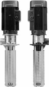
5 2 MTRE - pumps with built-in frequency-converter TM TM Applications Fig. 3 MTRE pumps MTRE pumps are MTR pumps with an E-motor, i.e. a motor with built-in frequency control. Frequency control enables continuously variable control of motor speed, which makes it possible to set the pump to operate in any duty point. The motors of the MTRE pumps are Grundfos MGE motors designed to EN standards. MTRE pumps are ideal for machining centres which operate with different machining processes and tools, as this will often result in different needs for flow and pressure. The following features and benefits are typical for choosing an MTRE pump: energy savings low heat input into the cooling lubricant increased cooling efficiency better performance of the machining centre simple integration with the machining centre. 5
6 3 Performance range 3. Performance range MTR, 5 Hz H 3 MTR 5 Hz 1 3 MTR 1s MTR 1 MTR 3 MTR 5 MTR 1 MTR 15 MTR MTR 32 MTR 45 MTR Q [l/min] Eta [%] Q [m³/h] Q [l/min] TM MTRE, 5 Hz H MTRE 5 Hz MTRE 1s MTRE 1 MTRE 3 MTRE 5 MTRE 1 MTRE 15 MTRE MTRE MTRE 45 MTRE Q [l/min] Eta [%] Q [m³/h] Q [l/min] TM
7 3 MTR, Hz H MTR Hz Performance range 1 MTR 1s MTR 1 MTR 3 MTR 5 MTR 1 MTR 15 MTR MTR 32 MTR 45 MTR Q [l/min] Eta [%] Q [m³/h] Q [l/min] TM MTRE, Hz H MTRE Hz 1 MTRE 1s MTRE 1 MTRE 3 MTRE 5 MTRE 1 MTRE 15 MTRE MTRE 32 MTRE 45 MTRE Q [l/min] Eta [%] Q [m³/h] Q [l/min] TM
8 3 Performance range MTRE high pressure, 5/ Hz p [kpa] H 3 15 MTRE 5/ Hz 1 1 MTRE 1s MTRE 1 MTRE Q [l/min] Q [m³/h] TM
9 3 SPK, 5 Hz p [kpa] 1 H 1 SPK 5 Hz Performance range SPK 2 SPK 4 SPK 8 SPK Q [l/min] Q [m³/h] TM SPK, Hz p [kpa] 1 H 1 SPK Hz SPK 1 SPK 2 SPK 4 SPK Q [l/min] Q [m³/h] TM
10 3 Performance range MTH, 5 Hz p [kpa] 1 H 1 MTH 5 Hz MTH 2 MTH Q [l/min] Q [m³/h] TM MTH, Hz p [kpa] 1 H 1 MTH Hz MTH 2 MTH Q [l/min] Q [m³/h] TM
11 3 MTA, 5 Hz H 12 1 MTA 5 Hz Performance range Q [l/min] Q [m³/h] TM MTA, Hz H MTA Hz Q [l/min] Q [m³/h] TM
12 3 Performance range MTA-H, 5 Hz H MTA-H 5 Hz Q [l/min] Q [m³/h] TM MTA-H, Hz H 18 MTA-H Hz Q [l/min] Q [m³/h] TM
13 3 EuP ready The MTR, MTRE, SPK and MTH pumps are energyoptimised and comply with the EuP Directive (Commission Regulation (EC) No 547/12) which has been effective since 1 January 13. As from this date, all pumps will be classified/graduated in the new minimum efficiency index (MEI). Minimum efficiency index Minimum efficiency index (MEI) means the dimensionless scale unit for hydraulic pump efficiency at best efficiency point (BEP), part load (PL) and overload (OL). The Commission regulation (EU) sets efficiency requirements to MEI.1 as from 1 January 13 and MEI. as from 1 January 15. An indicative benchmark for best-performing water pump available on the market as from 1 January 13 is determined in the regulation. The benchmark for most efficient water pumps is MEI.7. The efficiency of a pump with a trimmed impeller is usually lower than that of a pump with the full impeller diameter. The trimming of the impeller will adapt the pump to a fixed duty point, thus leading to reduced energy consumption. MEI is based on the full impeller diameter. The operation of this water pump with variable duty points may be more efficient and economic when controlled, for example, by using a variable-speed drive that matches the pump duty to the system requirement. Information on benchmark efficiency is available at Minimum efficiency index (MEI) Performance range Pump type MEI MTR1s-3/3.67 MTR1-3/3 >.7 MTR3-3/3 >.7 MTR5-3/3.57 MTR1-3/3 >.7 MTR15-3/3 >.7 MTR-3/3 >.7 MTR323/3 >.7 MTR45-3/3 >.7 MTR64-3/3 >.7 SPK1-3/3.56 SPK2-3/3 >.7 SPK4-3/3.14 SPK8-3/3.16 MTH2-3/3 >.7 MTH4-3/3 >.7 13
14 4 Product range 4. Product range MTR, MTRE Pump MTR, MTRE 1s MTR, MTRE 1 MTR, MTRE 3 MTR, MTRE 5 MTR, MTRE 1 MTR, MTRE 15 MTR, MTRE MTR, MTRE 32 MTR, MTRE 45 MTR, MTRE 64 5 Hz Rated flow rate [m 3 /h] Rated flow rate [l/min] Temperature range [ C] Maximum efficiency [%] MTR pumps Flow range [m 3 /h] Flow ratnge [l/min] Maximum head [bar] Motor power MTRE pumps Flow range [m 3 /h] Flow range [l/min] Maximum head [bar] Motor power Hz Rated flow rate [m 3 /h] Rated flow rate [l/min] Temperature range [ C] Maximum efficiency [%] MTR pumps Flow range [m 3 /h] Flow range [l/min] Maximum head [bar] Motor power MTRE pumps Flow range [m 3 /h] Flow range [l/min] Maximum head [bar] Motor power Material variants Pump head (A-version): cast iron, EN-GJL- Pump head (I-version): stainless steel, EN 1.48 Pipe connection A-version Internal thread G 1 1/4 G 1 1/4 G 1 1/4 G 1 1/4 G 2 G 2 G Rp 2 Rp 2 Rp Square flange with internal thread Rp 1 1/4 Rp 1 1/4 Rp 1 1/4 Rp 1 1/ Flange DN 65 DN DN I-version Internal thread G 1 1/4 G 1 1/4 G 1 1/4 G 1 1/4 G 2 G 2 G Rp 1 1/4 Rp 1 1/4 Rp 1 1/4 Rp 1 1/4 Rp 2 Rp 2 Rp Flange DN 65 DN DN Installation length Shaft seal * HUUV * Other shaft seals on request 14
15 4 SPK Pump SPK 1 SPK 2 SPK 4 SPK 8 5 Hz Rated flow rate [m 3 /h] Rated flow rate [l/min] Flow range [m 3 /h] Flow range [l/min] Maximum head [bar] Motor power Liquid temperature range [ C] Maximum efficiency [%] Range Hz Rated flow rate [m 3 /h] Rated flow rate [l/min] Flow range [m 3 /h] Flow range [l/min] Maximum head [bar] Motor power Liquid temperature range [ C] Maximum efficiency [%] Material variants Pump head (A-version): cast iron, EN-GJL- Pump head (I-version): stainless steel, EN 1.48 Pipe connection Product range A-version Internal thread G 3/4 G 3/4 G 3/4 G 1 1/4 Square flange with internal thread Rp 3/4 Rp 3/4 Rp 3/4 Rp 1 1/4 I-version Internal thread Installation length Rp 3/4 Rp 3/4 Rp 3/4 Rp 1 1/4 G 3/4 G 3/4 G 3/4 G 1 1/ Shaft seal * AUUV * Other shaft seals on request 15
16 4 Product range MTH Pump MTH 2 MTH 4 5 Hz Rated flow rate [m 3 /h] Rated flow rate [l/min] Temperature range [ C] Maximum efficiency [%] Flow range [m 3 /h] Flow range [l/min] Maximum head [bar] 1 5 Motor power P1 [W] Hz Rated flow rate [m 3 /h] Rated flow rate [l/min] 5 Temperature range [ C] Maximum efficiency [%] Flow range [m 3 /h] Flow range [l/min] Maximum head [bar] 1 5 Motor power P1 [W] Material variants Pump head (A-version): cast iron, EN-GJL- Pump head (I-version): stainless steel, EN 1.48 Pipe connection A-version Internal thread Rp 3/4 Rp 3/4 I-version Internal thread Rp 3/4 Rp 3/4 Installation length Shaft seal * AQQV * Other shaft seals on request 16
17 4 MTA Pump MTA 3 MTA MTA 9 MTA 1 MTA MTA H MTA H MTA 7H MTA 1H Range 5 Hz Rated flow rate [l/min] Temperature range [ C] - Flow range [l/min] Maximum head Hz Rated flow rate [l/min] Temperature range [ C] - Flow range [l/min] Maximum head Pipe connection Internal thread Material Rp 3/8 Rp 1/2 Rp 3/4 Rp 1 Rp 2 Rp 3/8 Rp 1/2 Rp 3/4 Rp 1 G 1/2 G 3/4 G 3/4 G 1 1/4 G 1 1/2 G 1/2 G 3/4 G 3/4 G 1 1/2" NPT 3/4" NPT 3/4" NPT 1 1/4" NPT 1 1/2" NPT 1/2" NPT 3/4" NPT 3/4" NPT 1" NPT Pump housing Cast iron Cast iron Cast iron Cast iron Cast iron Cast iron Cast iron Cast iron Cast iron Impeller PAA GF5 PAA GF5 PAA GF5 Bronze Bronze Bronze Bronze Bronze Bronze Installation length Product range Suction Top suction - Bottom suction - - * - * Impeller material: PAA GF5 17
18 5 Motors 5. Motors Motors for MTR and SPK pumps Motors for MTA pumps MTR and SPK pumps are fitted with a totally enclosed, fan-cooled, 2-pole Grundfos standard MG motor with principal dimensions according to IEC, DIN and British standards. Electrical tolerances according to EN 34. Mounting designation Efficiency class Enclosure class Insulation class Supply voltage, 5 Hz (- 1 %/+ 1 %) Supply voltage, Hz (- 1 %/+ 1 %) Up to 4 kw V 18/B 14 From 5.5 kw V 1/B kw kw IE2 IP55 For detailed electrical data see section "Motor data" on page 144. On request. Grundfos MG motors are available with curus approvals carried out by the Underwriters Laboratories Inc. according to UL 14 Electric motor standard. F.6-45 kw: 3 x 2-2/3-415 V kw 3 x V kw 3 x 3-415/6-69 V kw 3 x 2-277/3-4 V kw 3 x 2-255/3-4 V kw 3 x 2-277/3-4 V kw 3 x 3-4 V kw 3 x 3-4/6-69 V MTR pumps are also avavailable for these supply voltages Supply voltage, 5 Hz.6-45 kw 3 x -2/346-3 V Supply voltage, Hz.6-45 kw 3 x -23/346- V kw 3 x 8-23/4-4 V Efficiency class (only MTA, 75 W) Enclosure class Insulation class Supply voltage, 5 Hz (- 1 %/+ 1 %) Supply voltage, Hz (- 1 %/+ 1 %) We do not recommend operation via frequency converter. Grundfos standard motors Motor protection Single-phase Grundfos motors have a built-in thermal overload switch (IEC 34-:TP 2). Three-phase motors must be connected to a motorprotective circuit breaker in accordance with local regulations. Three-phase Grundfos motors from 3 kw and upwards have a built-in thermistor (PTC) according to DIN 482 (IEC 34-:TP 2). IE3 IP54 F 3 x 2-2/3-415 V 3 x V 3 x 2-2/3-4 V 3 x -2 V 3 x 8-23/4 V Motors for MTH pumps MTH motors are totally enclosed, fan-cooled, 2-pole Grundfos standard motors with principal dimensions according to IEC, DIN and British standards. Enclosure class Insulation class Supply voltage, 5 Hz (- 1 %/+ 1 %) Supply voltage, Hz (- 1 %/+ 1 %) IP55 F 3 x 2-2/3-415 V 3 x -2/346-3 V 3 x 2-255/3-4 V 3 x -23/346- V 3 x 8-23/4 V 18
19 5 Terminal box positions MTR, MTRE, SPK and MTH MTA Terminal box positions Pump 6 o'clock 3 o'clock 9 o'clock 12 o'clock (standard) MTR MTRE SPK MTH - Terminal box positions Pump 9 o'clock 3 o'clock 6 o'clock 12 o'clock (standard) MTA MTA ( ) ( ) MTA 9 ( ) ( ) MTA 1 ( ) ( ) ( ) MTA ( ) ( ) ( ) MTA H - - MTA H ( ) ( ) MTA 7H ( ) ( ) MTA 1H ( ) ( ) ( ) This position is possible. The pump can be ordered with the terminal box in this position or the terminal box can be turned to this position after delivery. ( ) This position is possible, but the terminal box cannot be turned to this position after delivery. Therefore the pump must be ordered with the terminal box in this position. - This position is not possible. Sound pressure level Pump MTR SPK Motor L pa [db(a)] 5 Hz Hz MTH < 7 < 7 MTA 3 < 45 < 45 MTA < 45 < 45 MTA 9 < 45 < 45 MTA 1 < 62 < 62 MTA < 62 < 62 MTA H < 45 < 45 MTA H < 45 < 45 MTA 7H < 45 < 45 MTA 1H < 62 < 62 Motors Position 3 o clock Fig. 4 Terminal box positions, top view Maximum number of starts Pump MTR SPK MTH Position 6 o clock Motor Position 9 o clock Recommended maximum number of starts per hour MTA All 25 Position 12 o clock TM The values have been measured according to EN ISO Viscosity and density The pumping of liquids with densities or kinematic viscosities higher than those of water will cause a considerable pressure drop, a drop in the hydraulic performance and a rise in the power consumption. In such situations, the pump should be fitted with a larger motor. If in doubt, contact Grundfos. 19
20 5 Motors Ambient temperature MTR, SPK Motor power If the ambient temperature exceeds the above temperature values, or the pump is installed at an altitude exceeding the above altitude values, the motor must not be fully loaded due to the risk of overheating. Overheating may result from excessive ambient temperatures or the low density and consequently low cooling effect of the air. In such cases, it may be necessary to use a motor with a higher rated output. Fig. 5 Legend Motor make Motor efficiency class Maximum ambient temperature at full load [ C] Maximum altitude above sea level Siemens Grundfos MG Grundfos MG IE Siemens IE [%] t[ C] Pos. The maximum motor output depends on the ambient temperature/altitude. Description kw motors (Siemens): kw motors (MG): kw motors (MG, IE2): kw motors (Siemens, IE2) m Example: A pump with a 1.1 kw IE2 MG motor: If this pump is installed 475 m above sea level, the motor must not be loaded more than 88 % of rated output. At an ambient temperature of 75 C, the motor must not be loaded more that 78 % of rated output. If the pump is installed 475 m above sea level at an ambient temperature of 75 C, the motor must not be loaded more than 88 % x 78 % = 68.6 % of rated output. TM MTH The motor used on an MTH pump is not shown in the list above, but the maximum ambient temperature at full load is the same as for MG motors. MTA Max. permissible ambient temperature [ C] Optional motors The Grundfos standard range of motors meets a wide variety of system requirements. For special applications or operating conditions, we offer custom-built motors, such as: ATEX-approved motors MG motors with anti-condensation heating unit motors with thermal protection. Grundfos blueflux Grundfos blueflux technology represents the best from Grundfos within energy-efficient motors and frequency converters. Grundfos blueflux solutions either meet or exceed legislative requirements, such as the EuP IE3 and IE4 grades. Fig. 6 Grundfos blueflux label To read more about the energy challenge and Grundfos blueflux, please visit grundfos.com/energy. Motors for MTRE pumps MTRE is an MTR pump with frequency-controlled motors, type MGE. MGE motors The MGE motor is a totally enclosed, fan-cooled, 2-pole Grundfos frequency-controlled motor with principal dimensions in accordance with the EN standards. Electrical tolerances comply with EN 34. MTRE pumps from.37 to 22 kw are fitted with threephase MGE motors as standard..37 to 1.5 kw single-phase MGE motors are available on request. See WinCAPS or WebCAPS on TM
21 5 Motor data for MGE Mounting designation * Efficiency class Enclosure class Insulation class Supply voltage (- 1 %/+ 1 %) MGE motor size (MTRE) Up to 4 kw V kw and up V1.75 to 2.2 kw Above IE4 level * 3 to 22 kw: IE3 The IE classification.37 and.55 kw does not apply for these sizes.37 to 2.2 kw IP55 (IP66 optional) 3 to 22 kw IP55.37 to 1.5 kw 1 x -2 V.37 to 2.2 kw 3 x 3-5 V 3 to 22 kw 3 x 3-4 V 1.1, 1.5, 2.2, 4., 5.5 kw 3 x -23 V, Hz Supply frequency 5/ Hz 5/ Hz Even though the MGE motor (.37 to 2.2 kw) has no defined efficiency class, the efficiency is still above the IE4 level including both motor and electronics. MGE motors, motor protection MGE motors incorporate thermal protection against slow overload and blocking (IEC 34-:TP 2). MTRE pumps require no external motor protection. MGE motors, ambient temperature Motor power Motor make Phases Maximum ambient temperature [ C] MGE MGE MGE 3 If the ambient temperature exceeds the above maximum ambient temperatures or the pump is installed at an altitude exceeding 1 metres, the motor must not be fully loaded due to the risk of overheating. Overheating may result from excessive ambient temperatures or the low density and consequently low cooling effect of the air. In such cases, it may be necessary to use a motor with a higher rated output. F Maximum altitude above sea level 1 Installation altitude Installation altitude is the height above sea level of the installation site. Motors installed up to 1 metres above sea level can be loaded 1 %. Motors installed more than 1 metres above sea level must not be fully loaded due to the low density and consequently low cooling effect of the air. MGE.37 to 2.2 kw [%] Fig. 7 MGE 3 to 22 kw [%] Fig Altitude Derating of motor output () in relation to altitude above sea level m Derating of motor output () in relation to altitude above sea level TM TM Motors 21
22 6 Control of MTRE pumps 6. Control of MTRE pumps Control options It is possible to communicate with MTRE pumps via the following control devices/systems: operating panel on the pump Grundfos GO Remote central management system. Operating panel on pump The operating panel on the E-pump terminal box makes it possible to change the setpoint settings manually. MGE.37 to 2.2 kw The operating condition of the pump is indicated by the Grundfos Eye on the operating panel. See fig. 9, pos. A. Grundfos GO Remote The pump is designed for wireless radio or infrared communication with the Grundfos GO Remote. The Grundfos GO Remote enables setting of functions and gives access to status overviews, technical product information and actual operating parameters. The Grundfos GO Remote offers three different mobile interfaces (MI). See fig A Fig. Grundfos GO Remote communicating with the pump via radio or infrared light + TM Fig. 9 Operating panel on MTRE pump,.37 to 2.2 kw MGE 3 to 22 kw TM TM Pos Description Grundfos MI 1: Consists of an Apple ipod touch 4G and a Grundfos cover. Grundfos MI 2: Add-on module which can be used in conjunction with Apple ipod touch 4G, iphone 4G or 4GS. Grundfos MI 4: Add-on module which can be used in conjunction with Apple ipod touch 5G or iphone 5. Grundfos MI 31: Separate module enabling radio or infrared communication. The module can be used in conjunction with an Android or ios-based Smartphone with Bluetooth connection. Fig. 1 Operating panel on MTRE pump, 3 to 22 kw 22
23 6 Central management system Communication with the E-pump is possible even if the operator is not present near the E-pump. Communication is enabled by connecting the E-pump to a central management system. This allows the operator to monitor the pump and to change control modes and setpoint settings. Control management system LonWorks, PROFIBUS, Modbus, GSM/GPRS, GRM and BACnet CIU 1: LonWorks CIU 15: PROFIBUS DP CIU : Modbus RTU CIU 25: GSM/GPRS CIU 271: GRM CIU 3: BACnet CIM 5: GENI CIM 1: LonWorks CIM 15: PROFIBUS DP CIM : Modbus RTU CIM 25: GSM/GPRS CIM 271: GRM CIM 3: BACnet Control modes for E-pumps Grundfos MTRE pumps are only available without pressure sensor. MTRE without sensor MTRE pumps without sensor are suitable in these situations: Uncontrolled operation is required. You want to retrofit another sensor in order to control the flow, temperature, differential temperature, liquid level, ph value, etc. at some arbitrary point in the system. MGE.37 to 2.2 kw These MTRE pumps without sensor can be set to either of these control modes: constant pressure constant differential pressure constant temperature constant differential temperature constant flow rate constant level constant curve constant other value. MGE 3 to 22 kw These MTRE pumps without sensor can be set to either of these control modes: controlled operation uncontrolled operation (factory setting). In controlled-operation mode, the pump adjusts its performance to the desired setpoint. See fig. 13. H Max. Control of MTRE pumps E-pump (3 to 7.5 kw) E-pump (.37 to 2.2 kw and to 22 kw) TM4 522 Min. Qset Q TM Fig. 12 Structure of a central management system Fig. 13 Constant-flow mode In uncontrolled-operation mode, the pump operates according to the constant curve set. See fig. 14. H Min. Fig. 14 Constant-curve mode Q Max. TM
24 6 Control of MTRE pumps Functional module for MGE.37 to 2.2 kw Advanced functional module (FM 3) The FM 3 is the standard functional module in all MGE motors from.37 to 2.2 kw. The module has a number of inputs and outputs enabling the motor to be used in advanced applications where many inputs and outputs are required. The FM 3 has these connections: three analog inputs one analog output two dedicated digital inputs two configurable digital inputs or open-collector outputs Grundfos Digital Sensor input and output two Pt1/1 inputs two LiqTec sensor inputs two signal relay outputs GENIbus connection. Connection terminals MTRE pumps have a number of inputs and outputs enabling the pumps to be used in advanced applications where many inputs and outputs are required. The number of available inputs and outputs depends on the selected functional module. Functional module 3 has been selected as standard for MTRE pumps. See fig. 15. As a precaution, the wires to be connected to the following connection groups must be separated from each other by reinforced insulation in their entire lengths. Inputs and outputs All inputs and outputs are internally separated from the mains-conducting parts by reinforced insulation and galvanically separated from other circuits. All control terminals are supplied by safety extra-low voltage (SELV), thus ensuring protection against electric shock. Signal relay outputs Signal relay 1: LIVE: Mains supply voltages up to 25 VAC can be connected to this output. SELV: The output is galvanically separated from other circuits. Therefore, the supply voltage or safety extra-low voltage can be connected to the output as desired. Signal relay 2: SELV: The output is galvanically separated from other circuits. Therefore, the supply voltage or safety extra-low voltage can be connected to the output as desired. Mains supply (terminals N, PE, L or L1, L2, L3, PE) A galvanically safe separation must fulfil the requirements for reinforced insulation including creepage distances and clearances specified in EN V* +24 V* +24 V* OC DI +24 V* +24 V* +24 V* +24 V*/5 V* OC DI +24 V* GND +24 V* Fig. 15 Connection terminals, FM 3 functional module V*/5 V* V*/5 V* V* A Y B GND GDS TX GDS RX +5 V* 7 AI2 * If an external supply source is used, there must be a connection to GND. NC C1 NO NC C2 NO GND DI4/OC2 Pt1/1 Pt1/1 AO GND AI3 DI2 LiqTec GND LiqTec DI3/OC1 AI1 DI1 +5 V GND GENIbus A GENIbus Y GENIbus B GND +24 V +24 V +5 V TM
25 6 Functional module for MGE 3 to 7.5 kw Advanced I/O module The Advanced I/O module is the standard functional module in all MGE motors from 3 to 7.5 kw. The module has a number of inputs and outputs enabling the motor to be used in advanced applications where many inputs and outputs are required. The Advanced I/O module has these connections: start/stop terminals three digital inputs one setpoint input one sensor input one analog output GENIbus connection. Connection terminals As a precaution, the wires to be connected to the following connection groups must be separated from each other by reinforced insulation in their entire lengths. Inputs Start/stop (terminals 2 and 3) digital inputs (terminals 1 and 9, 1 and 9, and 9) setpoint input (terminals 4, 5 and 6) sensor input (terminals 7 and 8) GENIbus (terminals B, Y and A). All inputs are internally separated from the mainsconducting parts by reinforced insulation and galvanically separated from other circuits. All control terminals are supplied with protective extralow voltage (PELV), thus ensuring protection against electric shock. NC C NO -1 V /4- ma 4- ma 1/ 1/ 1/ STOP RUN /4- ma -1 V 1K L1 L2 L3 B Y A 13: GND (frame) 12: Analog output : Digital input 4 1: Digital input 3 1: Digital input 2 9: GND (frame) 8: +24 V 7: Sensor input B: RS-485B Y: Screen A: RS-485A 6: GND (frame) 5: +1 V 4: Setpoint input 3: GND (frame) 2: Start/stop Switching follows the function of digital input 4. Factory setting: "Min." <-> "Not active". Fig. 16 Connection terminals, Advanced I/O module TM Control of MTRE pumps Output (relay signal, terminals NC, C, NO) The output is galvanically separated from other circuits. Therefore, the supply voltage or protective extra-low voltage can be connected to the output as desired. Analog output (terminal 12 and 13). Mains supply (terminals L1, L2, L3) A galvanic separation must fulfil the requirements for reinforced insulation including creepage distances and clearances specified in EN
26 6 Control of MTRE pumps Functional module for MGE to 22 kw Advanced I/O module The advanced I/O module is the standard functional module in all MGE motors from to 22 kw. The module has a number of inputs and outputs enabling the motor to be used in advanced applications where many inputs and outputs are required. The Advanced I/O module has these connections: start/stop terminals three digital inputs one setpoint input one sensor input (feedback sensor) one sensor 2 input one analog output two Pt1 inputs two signal relay outputs GENIbus connection. Connection terminals As a precaution, the wires to be connected to the following connection groups must be separated from each other by reinforced insulation in their entire lengths. Inputs Start/stop (terminals 2 and 3) digital inputs (terminals 1 and 9, 1 and 9, and 9) sensor input 2 (terminals 14 and 15) Pt1 sensor inputs (terminals 17, 18, 19 and ) setpoint input (terminals 4, 5 and 6) sensor input (terminals 7 and 8) GENIbus (terminals B, Y and A). All inputs are internally separated from the mainsconducting parts by reinforced insulation and galvanically separated from other circuits. All control terminals are supplied with protective extralow voltage (PELV), thus ensuring protection against electric shock. Output (relay signal, terminals NC, C, NO) The output is galvanically separated from other circuits. Therefore, the supply voltage or protective extra-low voltage can be connected to the output as desired. Analog output (terminal 12 and 13). Mains supply (terminals L1, L2, L3) A galvanic separation must fulfil the requirements for reinforced insulation including creepage distances and clearances specified in EN : Pt1 B 19: Pt1 B 18: Pt1 A 17: Pt1 A 16: GND (frame) 15: +24 V 14: Sensor input 2 13: GND 12: Analog output : Digital input 4 1: Digital input 3 1: Digital input 2 9: GND (frame) 8: +24 V 7: Sensor input B: RS-485B Y: Screen A: RS-485A 6: GND (frame) 5: +1 V 4: Setpoint input 3: GND (frame) 2: Start/stop Fig. 17 Connection terminals, Advanced I/O module TM
27 7 7. Construction MTR, MTRE 1s, 1, 3 and 5 Sectional drawing Construction TM Fig. 18 MTR, MTRE 1s, 1, 3 and 5 Materials Pos. Description Materials EN/DIN AISI/ASTM 2 Pump head A-version: cast iron EN-GJL- ASTM 25B I-version: stainless steel 1.48 AISI 316LN 4 Chamber Stainless steel AISI 34 8 Coupling Sintered metal 45 Neck ring PTFE 47a Bearing ring, stationary Silicium carbide 47b Bearing ring, rotating Silicium carbide 49 Impeller Stainless steel AISI Pump shaft Stainless steel 1.41 AISI Suction strainer Stainless steel AISI Strainer internal Stainless steel AISI Shaft seal HUUV/HUUE 121 Strap Stainless steel AISI Priming screw Stainless steel AISI 34 27
28 7 Construction MTR, MTRE 1, 15 and Sectional drawing TM Fig. 19 MTR, MTRE 1, 15 and Materials Pos. Description Materials EN/DIN AISI/ASTM 1a Motor stool Cast iron EN-GJL- ASTM 25B 2 Pump head A-version: cast iron EN-GJL- ASTM 25B I-version: stainless steel 1.48 AISI 316LN 4 Chamber Stainless steel AISI 34 8 Coupling Sintered metal 45 Neck ring PTFE 47a Bearing ring, stationary Silicium carbide 47b Bearing ring, rotating Silicium carbide 49 Impeller Stainless steel AISI Pump shaft A-version: stainless steel 1.57 AISI 431 I-version: stainless steel Suction strainer Stainless steel AISI Shaft seal HUUV/HUUE 121 Strap Stainless steel AISI Priming screw Stainless steel AISI 34 28
29 7 MTR, MTRE 32, 45 and 64 Sectional drawing Construction 18 TM TM Fig. MTR, MTRE 32, 45 and 64 Materials Pos. Description Materials EN/DIN AISI/ASTM 1a Motor stool Cast iron EN-GJL- ASTM 25B 2 Pump head A-version: cast iron EN-GJL- ASTM 25B I-version: stainless steel 1.48 AISI 316LN 4 Chamber Stainless steel AISI 34 8 Coupling Nodular iron EN-GJS-5-7 ASTM Air vent screw Stainless steel AISI Neck ring PTFE 47a Bearing ring, stationary Silicium carbide 47b Bearing ring, rotating Stainless steel AISI 94L 47c Bush Graflon, HY49 49 Impeller Stainless steel AISI Pump shaft A-version: stainless steel 1.57 AISI 431 I-version: stainless steel O-ring * A-version: NBR I-version: depending on rubber material in shaft seal 84 Suction strainer Stainless steel AISI Shaft seal HUUV/HUUE 121 Strap Stainless steel AISI 34 * Only used in pumps with empty chambers 29
30 7 Construction SPK 1, SPK 2 Sectional drawing TM Fig. 21 SPK 1, SPK 2 For information on the materials please see page 33. 3
31 7 SPK 4 Sectional drawing TM Construction Fig. 22 SPK 4 For information on the materials please see page
32 7 Construction SPK 8 Sectional drawing TM Fig. 23 SPK 8 For information on the materials, please see page
33 7 SPK materials Pos. Description Materials EN/DIN AISI/ASTM Pump head 2 Pump head A-version: cast iron EN-GJL- ASTM 25B I-version: stainless steel 1.48 AISI 316LN 7 Coupling guard Stainless steel AISI 34 7a Screw Stainless steel 28 Set screw Stainless steel Extension pipe Stainless steel AISI 34 Construction Chamber without bearing 3 Chamber, empty Stainless steel AISI 34 3a Chamber, empty Stainless steel AISI 34 4 Chamber Stainless steel AISI Neck ring SPK 1, 2 and 4: PPS with % glass fibre SPK 8: Tin/bronze a Disc for neck ring PTFE 64 Spacing pipe Stainless steel 1.41 AISI Spacing pipe Stainless steel 1.41 AISI 316 Chamber with bearing 4a Chamber Stainless steel AISI 34 Bearing in chamber Ceramic Al 2 O % Hilox TM 45 Neck ring SPK 1, 2 and 4: PPS with % glass fibre SPK 8: Tin/bronze a Disc for neck ring PTFE 47a Bearing ring Tungsten carbide 64a Spacing pipe Stainless steel 1.41 AISI b Spacing pipe Stainless steel 1.41 AISI 316 Bottom chamber 5a Chamber Stainless steel AISI Neck ring SPK 1, 2 and 4: PPS with % glass fibre SPK 8: Tin/bronze a Disc for neck ring PTFE 64c Spacing pipe Stainless steel 1.41 AISI 316 Inlet part 84 Suction strainer Stainless steel AISI Inlet part Stainless steel AISI 34 84b Set screw Stainless steel Shaft 51 Spline shaft Stainless steel 1.57 AISI Neck ring Stainless steel AISI Stop ring Stainless steel AISI c Neck ring Stainless steel 1.41 AISI Washer Stainless steel AISI Locking nut Stainless steel 1.41 AISI a Spacing pipe Stainless steel AISI 34 2 Spacing pipe Stainless steel AISI Priming screw Stainless steel 1.41 AISI 316 Impeller 49 Impeller Stainless steel AISI 34 49d Impeller, lower Stainless steel AISI 34 Strap 26 Strap Stainless steel AISI Nut Stainless steel 66a Washer Stainless steel Coupling 8 Coupling Sintered metal 9 Hexagon socket head screw Steel 1 Shaft pin Stainless steel AISI 34 33
34 7 Construction MTH 2 Sectional drawing TM Fig. 24 MTH 2 Material specification Pos. Description Materials EN/DIN AISI/ASTM 2 Pump head A-version: cast iron EN-GJL- ASTM 25B I-version: stainless steel 1.48 AISI 316LN 4 Chamber I-version: stainless steel AISI Neck ring PTFE 47a Bearing ring Tungsten carbide 49 Impeller Stainless steel AISI Pump shaft Stainless steel 1.57 AISI Suction strainer, 2 mm holes Stainless steel AISI Strainer, internal Stainless steel AISI Shaft seal AQQV 122 Priming screw Stainless steel AISI 34 34
35 7 MTH 4 Sectional drawing Construction TM Fig. 25 MTH 4 Material specification Pos. Description Materials EN/DIN AISI/ASTM 2 Pump head A-version: cast iron EN-GJL- ASTM 25B I-version: stainless steel 1.48 AISI 316LN 4 Chamber Stainless steel AISI Neck ring PTFE 47a Bearing ring Tungsten carbide 49 Impeller Stainless steel AISI Pump shaft Stainless steel 1.57 AISI Suction strainer, 2 mm holes Stainless steel AISI Strainer, internal Stainless steel AISI Shaft seal AQQV 122 Priming screw Stainless steel AISI 34 35
36 7 Construction MTA 3,, 9, H, H, 7H TM Pos. Description Materials EN/DIN AISI/ASTM JIS 2 Pump head Cast iron GG A48-CL3 FC 6 Pump housing Cast iron GG A48-CL3 FC 26 Screw Stainless steel A SUS34 49 Impeller MTA 3,, 9, 7H* PAA GF5 MTA H, H, 7H** Bronze casting G-CuZn-5ZnPb C92 BC7 51 Shaft with rotor Steel C45 A S45C 7 Vortex preventer MTA 9 PP 79 Thrower NBR 79a Splash ring Steel 1623 ST 12 A366 SPCC 188 Cross-head screw Stainless steel A SUS34 188a Washer Stainless steel A SUS34 188b Hexagon nut Stainless steel A SUS34 Terminal box Aluminium * MTA 7H, bottom suction ** MTA 7H, top suction 36
37 7 MTA 1,, 1H TM Construction Pos. Description Materials EN/DIN AISI/ASTM JIS 2 Pump head Cast iron GG A48-CL3 FC 6 Pump housing Cast iron GG A48-CL3 FC 26 Screw Stainless steel A SUS34 49 Impeller Bronze casting G-CuZn-5ZnPb C92 BC7 MTA 1 PAA GF 5 51 Shaft with rotor Steel C45 A S45C 7 Vortex preventer MTA 1 PP 79 Thrower NBR 79a Splash ring Steel 1623 ST 12 A366 SPCC 188 Cross-head screw Stainless steel A SUS34 188a Washer Stainless steel A SUS34 188b Hexagon nut Stainless steel A SUS34 Terminal box Aluminium 37
38 7 Construction Shaft seals The operating range of the shaft seal depends on operating pressure, pump type, type of shaft seal and liquid temperature. Shaft seal, MTR, MTRE p [bar] HUUV t [ C] TM Shaft seal * HUUV Description O-ring seal (cartridge type), balanced, tungsten carbide/tungsten carbide, FKM Temperature range [ C] * Other shaft seals on request Shaft seal, SPK p [bar] AUUV t [ C] TM Shaft seal * AUUV Description O-ring seal with fixed seal driver, tungsten carbide/tungsten carbide, FKM Temperature range [ C] * Other shaft seals on request Shaft seal, MTH p [bar] AQQV t [ C] TM Shaft seal * AQQV Description O-ring seal with fixed seal driver, silicon carbide, silicon carbide, FKM Temperature range [ C] * Other shaft seals on request 38
39 8 8. Identification MTR, MTRE type key Example MTR E 32 (s) -2 /1-1 -A -F -A -H UU V Pump type Pump with integrated frequency control Rated flow rate [m 3 /h] All impellers with reduced diameter (only MTR 1s) Number of chambers, see fig. 26 Number of impellers, see fig. 26 Number of impellers with reduced diameter Pump version A Basic version B Oversize motor C Suction pipe E Pump with certificate/approval F 1 C version H Horizontal version HS High pressure J Pump with different max. speed P Undersize motor T Double oversize X Special version Pipe connection F DIN flange G ANSI flange J JIS flange M Square flange with internal thread W Internal thread WB NPT internal thread X Special version Materials A Basic version I Wetted parts EN/DIN 1.431/AISI 34 X Special version Shaft seal H Balanced cartridge seal Q Silicon carbide U Tungsten carbide B Carbon E EPDM F FXM K FFKM V FKM Identification Number of chambers Number of impellers TM Fig. 26 MTR pump 39
40 8 Identification SPK type key Example SPK E 2-15 /8 A -W -A A UU V Pump type Pump with integrated frequency control Rated flow rate [m 3 /h] Number of chambers, see fig. 27 Number of impellers, see fig. 27 Pump version A Basic version B Oversize motor C Suction pipe E Pump with certificate/approval F 1 C version H Horizontal version L With extension pipe P Undersize motor T Double oversize X Special version Pipe connection M Square flange with internal thread W Internal thread WB NPT internal thread Materials A Basic version I Pump head of stainless steel Shaft seal A O-ring seal with fixed seal driver B Bellows seal, rubber C O-ring seal with spring as seal driver R O-ring seal, type A, with reduced seal faces A Carbon metal-impregnated B Carbon resin-impregnated Q Silicon carbide U Tungsten carbide V Metal oxides, ceramic E EPDM K FFKM P NBR V FKM Number of chambers Number of impellers TM Fig. 27 SPK pump
41 8 MTH type key Example MTH 2-6 /3 -A -W -A -A UU V Pump type Rated flow rate [m 3 /h] Number of chambers, see fig. 28 Number of impellers, see fig. 28 Pump version A Basic version C Suction pipe X Special version Pipe connection W Internal thread WB NPT internal thread Materials A Basic version I Pump head of stainless steel Shaft seal A O-ring seal with fixed seal driver B Bellows seal, rubber C O-ring seal with spring as seal driver R O-ring seal, type A, with reduced seal faces A Carbon, metal-impregnated B Carbon, resin-impregnated Q Silicon carbide U Tungsten carbide V Metal oxides, ceramic E EPDM K FFKM P NBR V FKM MTA type key Example MTA 3 H -15 -A -W -A -T Pump type Pump size Pressure type Installation length Pump version A = standard version Thread type W = internal thread WB = internal NPT thread Impeller material A = PAA GF5 B = bronze Suction T = top B = bottom Fig. 29 MTA pump Installation length TM5 121 Identification Number of chambers Number of impellers TM Fig. 28 MTH pump 41
42 9 Installation 9. Installation Installation of MTR, MTRE pumps MTR, MTRE 1s, 1, 3, 5, 1, 15 and pumps can be installed both vertically and horizontally. MTR, MTRE 32, 45, 64 pumps must be installed in a vertical position. 25 mm B A TM Fig. 33 MTR, MTRE 1, 15 and Vertical Horizontal Fig. 3 Installation of a MTR, MTRE pump TM Fig. 34 MTR, MTRE 32, 45 and 64 A 25 mm TM Fig. 31 On horizontally installed MTR, MTRE pumps with motors from 5.5 kw and up, the motors have feet and must be supported. TM Installation of SPK pumps SPK pumps can be installed both vertically and horizontally. If the SPK pump is installed horizontally, the drain hole in the pump head must be closed. The pumps are designed to provide full performance down to a level of A mm above the bottom of the suction strainer. At a liquid level between A and B mm above the bottom of the suction strainer, the built-in priming screw will protect the pump against dry running. Note: MTR, MTRE 32, 45 and 64 pumps have no priming screw. Vertical Fig. 35 Installation of a SPK pump Horizontal TM Pump type A B MTR, MTRE 1s, 1, 3, MTR, MTRE 1, 15, 5 25 MTR, MTRE 32, 45, The distance between the pump and the tank bottom must be minimum 25 mm. To enable a very low liquid level of mm above the bottom of the suction strainer, a priming screw is fitted below the bottom chamber. This protects the pump against dry running down to 25 mm above the bottom of the suction strainer. The distance between pump and tank bottom must be minimum 25 mm. B 25 mm Fig. 32 MTR, MTRE 1s, 1, 3 and 5 A TM mm 25mm 25mm TM Fig. 36 SPK 42
43 9 Installation of MTH pumps MTH pumps must be installed vertically. Liquid level MTA with top suction Installation Vertical Fig. 37 Installation of an MTH pump Horizontal To enable a low liquid level of mm above the bottom of the suction strainer, a priming screw is fitted below the bottom chamber. This protects the pump against dry running down to 25 mm above the bottom of the suction strainer. The distance between pump and tank bottom must be minimum 25 mm. TM Tank H1 Max. liquid level Min. liquid level H2 H3 Fig. MTA with top suction TM mm mm 25mm Fig. 38 Minimum distance between pump and tank Installation of MTA pumps MTA pumps are designed for vertical mounting in a tank. TM Pump * Min. liquid level (full performance). ** Min. permissible liquid level (reduced performance). MTA with bottom suction H1 H2 * H3 ** MTA MTA 7 45 MTA MTA 1 7 MTA H 15 5 MTA H 7 MTA 7H 5 MTA 1H Min. 5 mm (MTA 1, and 1H) Tank H1 Max. liquid level Vertical Fig. 39 Mounting position Horizontal Provide a clearance of minimum 5 mm above the motor to ensure cooling of fan-cooled motors (MTA 1, and 1H). The pump is designed for indoor operation only. Note: The motor must not be exposed to direct water/ liquid sprays. TM Fig. 41 MTA with bottom suction Pump Min. liquid level H2 H4 H1 H2 * H4 MTA MTA 1 MTA MTA 1 25 MTA TM * Min. liquid level (full performance). 43
44 9 Installation Electrical installation MTR, SPK and MTH pumps can be fitted with a 1-pin multi-plug connection, type Han 1 ES. The purpose of a multi-plug connection is to make the electrical installation and the service of the pump easier. The multi-plug functions as a plug-and-pump device. The following drawings show where the multi-plug is positioned on the motor. Multi-plug connection (Han 1 ES) Dimensions Fig. 44 Motor with multi-plug Motor Frame size A B TM Multi-plug connection (Han 1 ES) TM MG MG MG MG MG MG (5.5 kw) MG (7.5 kw) Plug connections TM W2 U2 V Fig. 42 Multi-plug on a Grundfos MG motor Multi-plug connection (Han 1 ES) U1 V1 W TM Fig. 45 From motor L1 L2 L TM TM Fig. 43 Multi-plug type Han 1 ES On request, the following motors can be supplied with a multi-plug connection (type Han 1 ES): motors for MTR/SPK up to 7.5 kw all MTH motors. Technical data for multi-plug Material description Material Description Material GD-Al Si 8 Cu 3 Surface Powder paint Clip for locking Stainless steel Housing gasket NBR rubber Temperature range [ C] Enclosure class IP65 at DIN 5 in closed position Type Han 1E Fig. 46 Plug connections for star connection L1 L2 L Fig. 47 Plug connections for delta connection. Fishplates for connections are located in the plug. TM
45 1 1. Selection and sizing Selection of pumps Selection of pumps should be based on the following parameters: the duty point of the pump dimensional data such as pressure loss as a result of height differences, friction loss in the pipework, pump efficiency etc. minimum inlet pressure - NPSH. Duty point of the pump From a duty point it is possible to select a pump on the basis of the curve charts shown in the chapter of. starting on page 51. p H [kpa] MTR, MTRE 32 5 Hz ISO 996:1999 Annex A Dimensional data When sizing a pump the following aspects must be taken into account: required flow rate and pressure at the draw-off point pressure loss as a result of height differences (H geo ) friction loss in the pipework (H f ). It may be necessary to account for pressure loss in connection with long pipes, bends or valves, etc. best efficiency at the estimated duty point NPSH value for calculation of the NPSH value, see "Minimum inlet pressure - NPSH" on page 5. Efficiency Before determining the point of best efficiency, the operating pattern of the pump needs to be identified. Is the pump expected always to operate in the same duty point, select an MTR, MTH, MTA pump which is operating at a duty point corresponding to the best efficiency of the pump. Selection and sizing p H [kpa] MTR, MTRE 32 5 Hz ISO 996:1999 Annex A Duty point Q [l/min] [hp] Q [m³/h] 2. Eta 1/ /3 1. Eta [%] Q [l/min] Q [l/min] p H NPSH [kpa] QH 29 rpm 1/1 8 1 QH 29 rpm 2/3 NPSH Q [l/min] Fig. 48 Example of a curve chart TM [hp] p [kpa] H Q [m³/h] 1/1 2/ Q [l/min] QH 29 rpm 1/1 QH 29 rpm 2/ Q [l/min] Eta NPSH Eta [%] NPSH Best efficiency TM Fig. 49 Example of an MTR pump s duty point 45
46 1 Selection and sizing As the pump is sized on the basis of the highest possible flow, it is important always to have the duty point to the right on the efficiency curve (eta) in order to keep efficiency high when the flow drops. Eta Fig. 5 Best efficiency Q [ m3 /h ] TM Note: The approximated formulas apply on condition that the system characteristic remains unchanged for n n and n x and that it is based on the formula H = k x Q 2 where k is a constant. The power equation implies that the pump efficiency is unchanged at the two speeds. In practice this is not quite correct. Finally, it is worth noting that the efficiencies of the frequency converter and the motor must be taken into account if a precise calculation of the power saving resulting from a reduction of the pump speed is wanted. Required flow rate, required pressure H Q n n n = Q n x x H n H f Fig. 51 Dimensional data H geo TM H x Eta Q x n x Q n n n Q H n n n = H n x x Normally, MTRE pumps are used in applications characterized by a variable flow rate. Consequently, it is not possible to select a pump that is operating constantly at optimum efficiency. In order to achieve optimum operating economy, the pump should be selected on the basis of the following criteria: The maximum duty point should be as close as possible to the QH curve of the pump. The required duty point should be positioned so that is close to the max. point of the QH curve. Between the minimum and maximum performance curves, MTRE pumps have an infinite number of performance curves each representing a specific speed. Therefore it may not be possible to select a duty point close to the max. curve. P n P n x n n Q x Q n n n Px Fig. 53 Affinity equations n x Q Q η n η x P n n n = P n x x TM H Max. curve Legend Min. curve Q [m³/h] Fig. 52 Min. and max. performance curves In situations where it is not possible to select a duty point close to the max. curve, the affinity equations below can be used. The head (H), the flow rate (Q) and the input power (P) are all the appropriate variables you need to be able to calculate the motor speed (n). TM H n Rated head H x Current head Q n Flow rate [m 3 /h] Q x Current flow rate [m 3 /h] n n Rated motor speed [min -1 ] n x Current motor speed [min -1 ] η n Rated efficiency [%] η x Current efficiency [%] 46
47 1 WinCAPS and WebCAPS WinCAPS and WebCAPS are both selection tools offered by Grundfos. The two tools make it possible to calculate an MTRE pump s specific duty point and energy consumption. By entering the sizing data of the pump, WinCAPS and WebCAPS can calculate the exact duty point and energy consumption. For further information see page 159. Pressure loss During operation pressure losses occur in all centrifugal pumps. The below curves illustrate the pressure losses for pumped liquid passing through one empty chamber. An empty chamber is a chamber without an impeller. H MTR 5/ Hz MTR 1 H MTR 3 MTR 5 MTR 5/ Hz Q [l/min] Q [m³/h] Fig. 55 Pressure losses of pumped liquid passing through an empty chamber for MTR 3 and MTR 5 pumps TM Selection and sizing H MTR 5/ Hz MTR1S MTR. 1 3 Q [l/min] Q [m³/h] Fig. 54 Pressure losses of pumped liquid passing through an empty chamber for MTR 1s and MTR 1 pumps TM MTR 1 MTR Q [l/min] Q [m³/h] TM Fig. 56 Pressure losses of pumped liquid passing through an empty chamber for MTR 1, MTR 15 and MTR pumps As MTR, MTRE 32, 45 and 64 pumps have holes in the guide vanes, no pressure losses occur in the empty chambers of these pumps. 47
48 1 Selection and sizing Calculation of the reduced head of a pump with empty chambers Calculation of pressure loss in empty chambers From the above curves and the curve charts of each pump type starting on page 45, it is possible to calculate the reduced head of a pump with empty chambers. The calculation can be made as shown below. Example: Pump type MTR 5-18/7 Flow Q (duty point) 6 [m 3 /h] Head (duty point) 9 The selected pump is an MTR 5-18/18 with empty chambers, see type keys on page 39. From the above pressure loss curve of MTR 5, it appears that the pressure loss of each empty chamber at 6 m 3 /h is.14. This results in a total pressure loss of: (Total pressure loss) =.14 = 1.54 The reduced head of the MTR 5-18/7 pump including pressure losses caused by empty chambers is: Head = = The head 33 metres is read from the performance curve for an MTR 5-18/7, see page
49 1 Viscosity Maximum kinematic Pump viscosity of pumped liquid [cst] = [mm 2 /s] MTR 1s, 1, 3, 5 5 MTR 1, 15,, 32, 45, 64 1 SPK 5 MTH 5 MTA 75 The pumping of liquids with densities or kinematic viscosities higher than those of water will cause a considerable pressure drop, a drop in the hydraulic performance and a rise in the power consumption. In such situations the pump should be equipped with a larger motor. If in doubt, contact Grundfos. The following examples show the drop in the hydraulic performance of MTR, MTRE pumps pumping oil with a density of 872 kg/m 3 but with three different kinematic viscosities. Selection and sizing H(m) 5 MTR, MTRE 5-1 H(m) 5 MTR, MTRE 5-1 H(m) 5 MTR, MTRE Q(m 3 /h) TM Q(m 3 /h) TM Q(m 3 /h) TM H(m) MTR, MTRE -1 H(m) MTR, MTRE -1 H(m) MTR, MTRE Q(m 3 /h) TM Q(m 3 /h) TM Q(m 3 /h) TM H(m) MTR 64-5/5 H(m) MTR 64-5/5 H(m) MTR 64-5/ Q(m 3 /h) TM Q(m 3 /h) TM Q(m 3 /h) TM Fig. 57 Drop in the hydraulic performance of MTR, MTRE pumps pumping oil with three different kinematic viscosities. Key Position Density [kg/m 3 ] Kinematic viscosity [cst] = [mm 2 /s] For further information about pump performance when pumping liquids with densities or kinematic viscosities higher than those of water, see WinCAPS or WebCAPS. WinCAPS and WebCAPS are product selection systems offered by Grundfos, see page
50 1 Selection and sizing Kinematic viscosity of different oils The curves below show the kinematic viscosity of different oils in relation to oil temperature. Centistokes To avoid cavitation, make sure that there is a minimum pressure on the suction side of the pump. The maximum suction lift "H" in metres head can be calculated as follows: H = p b x NPSH - H f - H v - H s 9 p b = Barometric pressure in bar. Barometric pressure can be set to 1 bar). In closed systems, p b indicates the system pressure in bar. NPSH = Net Positive Suction Head in metres head. (To be read from the NPSH curve at the highest flow rate the pump will be delivering). H f = Friction loss in suction pipe in metres head. (At the highest flow rate the pump will be delivering). H v = Vapour pressure in metres head. H s = Safety margin = minimum.5 metre head If the "H" calculated is positive, the pump can operate at a suction lift of maximum "H" metres head. If the "H" calculated is negative, an inlet pressure of minimum "H" metres head is required T [ C] T [ F] Fig. 58 Kinematic viscosity of different oils in relation to oil temperature Key to kinematic viscosities of different oils Curve number Liquid 1 Water 2 Honing oil 3 Grinding oil 4 Hydraulic oil (ISO VG1) 5 Thermal oil 6 Cutting oil 7 Hydraulic oil (ISO VG46) 8 Motor oil (W-5) 9 Gear oil Minimum inlet pressure - NPSH We recommend calculating the inlet pressure "H" when the following aspects apply: the liquid temperature is high the flow is significantly higher than the flow rate water is drawn from depths water is drawn through long pipes inlet conditions are poor. TM Hf Pb Q H , 9 Hv 6, 5, 4, 7 3, 2, 1,5 5 1,,8,6 3,4,3,2 1,1 Fig. 59 Minimum inlet pressure - NPSH tm ( C) Hv (m) Note: In order to avoid cavitation, never select a pump whose duty point is too far to the right on the NPSH curve. Always check the NPSH value of the pump at the highest possible flow rate. TM TM
51 . Introduction to performance curves How to read the curve charts Number of stages. First figure: number of stages; second figure: number of reduced-diameter impellers. p [kpa] 1 1 H Pump type, frequency and ISO standard MTR, MTRE 32 5 Hz ISO 996:1999 Annex A QH curve for the individual pump. The bold curves indicate the recommended performance range for best efficiency The power curves indicate pump input power per stage. Curves are shown for complete (1/1) and reduced (2/3) impellers. [hp] Q [l/min] Q [m³/h] 2. Eta 1/ / Q [l/min] p H NPSH [kpa] QH 29 rpm 1/1 8 1 QH 29 rpm 2/3 NPSH Q [l/min] Eta [%] 2 The eta curve shows the efficiency of the pump. The eta curve is an average curve of all the pump types shown in the chart The NPSH curve is an average curve for all the variants shown. When sizing the pumps, add a safety margin of at least.5 m. TM Fig. Example of an MTR, MTRE curve chart Guidelines to performance curves The guidelines below apply to the curves shown on the following pages: 1. Tolerances to ISO 996, Annex A, if indicated. 2. The motors used for the measurements are standard Grundfos motors (MG or MGE). 3. Measurements have been made with airless water at a temperature of C. 4. The curves apply to a kinematic viscosity of υ = 1 mm 2 /s (1 cst). 5. Due to the risk of overheating, the pumps should not be used at a flow below the minimum flow rate. 6. QH curves of the individual pumps are based on current motor speeds. The curve below shows the minimum flow rate as a percentage of the nominal flow rate in relation to the liquid temperature. Qmin [%] t [ C] Fig. 61 Minimum flow rate TM
52 MTR, MTRE, 5 Hz MTR, MTRE, 5 Hz MTR, MTRE 1s, 5 Hz p [kpa] H MTR, MTRE 1s 5 Hz ISO 996:1999 Annex A Q [l/min] [hp] p [kpa] H Q [m³/h] Q [l/min] QH 29 rpm Eta Eta [%] 3 1 NPSH NPSH Q [l/min] 2 TM
53 Dimensional sketches Square flange MTR, MTRE, 5 Hz (A-version) (I-version) (A- and I-version) (I-version) (A-version) TM Dimensions and weights MTR MTRE Pump type Dimensions Net Dimensions Net weight weight A B C AC D2 AD AG [kg] A B C AC D2 AD AG [kg] MTR 1s-2/ MTR 1s-3/ MTR 1s-4/ MTR, MTRE 1s-5/ MTR 1s-6/ MTR 1s-7/ MTR, MTRE 1s-8/ MTR 1s-9/ MTR 1s-1/ MTR 1s-/ MTR, MTRE 1s-12/ MTR 1s-13/ MTR 1s-15/ MTR 1s-17/ MTR, MTRE 1s-19/ MTR 1s-21/ MTR 1s-22/ MTR 1s-23/ MTR, MTRE 1s-25/ MTR 1s-26/ MTR 1s-27/ MTR, MTRE 1s-3/ MTR 1s-33/ MTR, MTRE 1s-36/ The maximum immersion depth is 16 mm. See page 156. For information about electrical data, see section 12. Motor data on page
54 MTR, MTRE, 5 Hz MTR, MTRE 1, 5 Hz p [kpa] H MTR, MTRE 1 5 Hz ISO 996:1999 Annex A Q [l/min] Q [m³/h] Eta Eta [%]. H Q [l/min] QH 29 rpm NPSH 4 3 NPSH Q [l/min] 2 TM
55 Dimensional sketches Square flange MTR, MTRE, 5 Hz (A-version) (I-version) (A- and I-version) (I-version) (A-version) TM Dimensions and weights T MTR MTRE Pump type Dimensions Net Dimensions Net weight weight A B C AC D2 AD AG [kg] A B C AC D2 AD AG [kg] MTR 1-2/ MTR 1-3/ MTR 1-4/ MTR, MTRE 1-5/ MTR 1-6/ MTR 1-7/ MTR, MTRE 1-8/ MTR 1-9/ MTR 1-1/ MTR 1-/ MTR, MTRE 1-12/ MTR 1-13/ MTR, MTRE 1-15/ MTR 1-17/ MTR 1-19/ MTR 1-21/ MTR 1-22/ MTR, MTRE 1-23/ MTR 1-25/ MTR 1-26/ MTR 1-27/ MTR, MTRE 1-3/ MTR 1-33/ MTR, MTRE 1-36/ The maximum immersion depth is 16 mm. See page 156. For information about electrical data, see section 12. Motor data on page
56 MTR, MTRE, 5 Hz MTR, MTRE 3, 5 Hz p [kpa] H MTR, MTRE 3 5 Hz ISO 996:1999 Annex A Q [l/min] Q [m³/h] Eta Eta [%]. H Q [l/min] NPSH QH 29 rpm NPSH Q [l/min] 1 TM
57 Dimensional sketches Square flange MTR, MTRE, 5 Hz (A-version) (I-version) (A- and I-version) (I-version) (A-version) TM Dimensions and weights MTR MTRE Pump type Dimensions Net Dimensions Net weight weight A B C AC D2 AD AG [kg] A B C AC D2 AD AG [kg] MTR 3-2/ MTR 3-3/ MTR 3-4/ MTR, MTRE 3-5/ MTR 3-6/ MTR 3-7/ MTR, MTRE 3-8/ MTR 3-9/ MTR 3-1/ MTR, MTRE 3-/ MTR 3-12/ MTR 3-13/ MTR, MTRE 3-15/ MTR 3-17/ MTR, MTRE 3-19/ MTR 3-21/ MTR 3-22/ MTR 3-23/ MTR, MTRE 3-25/ MTR 3-26/ MTR 3-27/ MTR, MTRE 3-3/ MTR 3-33/ MTR, MTRE 3-36/ The maximum immersion depth is 16 mm. See page 156. For information about electrical data, see section 12. Motor data on page
58 MTR, MTRE, 5 Hz MTR, MTRE 5, 5 Hz p [kpa] H MTR, MTRE 5 5 Hz ISO 996:1999 Annex A Q [l/min] Q [m³/h] Eta Eta [%].1.5. H Q [l/min] QH 29 rpm NPSH NPSH Q [l/min] 1 TM
59 Dimensional sketches Square flange MTR, MTRE, 5 Hz (A-version) (I-version) (A- and I-version) (I-version) (A-version) TM Dimensions and weights MTR Dimensions The maximum immersion depth is 16 mm. See page 156. For information about electrical data, see section 12. Motor data on page 144. MTRE Dimensions Pump type Net Net weight weight A B C AC D2 P AD AG [kg] A B C AC D2 P AD AG [kg] MTR, MTRE 5-2/ MTR 5-3/ MTR, MTRE 5-4/ MTR, MTRE 5-5/ MTR 5-6/ MTR 5-7/ MTR, MTRE 5-8/ MTR 5-9/ MTR, MTRE 5-1/ MTR 5-12/ MTR 5-14/ MTR, MTRE 5-16/ MTR 5-17/ MTR 5-18/ MTR 5-19/ MTR, MTRE 5-/ MTR 5-21/ MTR, MTRE 5-22/ MTR 5-24/ MTR 5-26/ MTR, MTRE 5-29/ MTR, MTRE 5-32/
60 MTR, MTRE, 5 Hz MTR, MTRE 1, 5 Hz p [kpa] 1 H MTR, MTRE 1 5 Hz ISO 996:1999 Annex A Q [l/min] Q [m³/h].4 Eta Eta [%]. H Q [l/min] 29 rpm NPSH NPSH Q [l/min] 2 TM
61 Dimensional sketches MTR, MTRE, 5 Hz (A- and I-version) (A- and I-version) TM Dimensions and weights MTR Dimensions The maximum immersion depth is 8 mm. See page 156. For information about electrical data, see section 12. Motor data on page 144. MTRE Dimensions Pump type Net weight A B C AC D2 P AD AG [kg] A B C AC D2 P AD AG MTR, MTRE 1-2/ MTR, MTRE 1-2/ MTR, MTRE 1-3/ MTR, MTRE 1-4/ MTR 1-5/ MTR, MTRE 1-6/ MTR 1-7/ MTR 1-8/ MTR, MTRE 1-9/ MTR 1-1/ MTR, MTRE 1-12/ MTR 1-14/ MTR, MTRE 1-16/ MTR 1-18/ MTR 1-/ MTR, MTRE 1-22/ Net weight [kg] 61
62 MTR, MTRE, 5 Hz MTR, MTRE 15, 5 Hz p [kpa] H MTR, MTRE 15 5 Hz ISO 996:1999 Annex A Q [l/min] Q [m³/h] Eta Eta [%]. H Q [l/min] 29 rpm NPSH NPSH Q [l/min] 2 TM
63 Dimensional sketches MTR, MTRE, 5 Hz (A- and I-version) (A- and I-version) TM Dimensions and weights MTR Dimensions The maximum immersion depth is 133 mm. See page 156. For information about electrical data, see section 12. Motor data on page 144. MTRE Dimensions Pump type Net Net weight weight A B C AC D2 P AD AG [kg] A B C AC D2 P AD AG [kg] MTR, MTRE 15-2/ MTR, MTRE 15-2/ MTR, MTRE 15-3/ MTR 15-4/ MTR, MTRE 15-5/ MTR 15-6/ MTR, MTRE 15-7/ MTR 15-8/ MTR, MTRE 15-9/ MTR 15-1/ MTR 15-12/ MTR, MTRE 15-14/ MTR 15-16/ MTR, MTRE 15-17/
64 MTR, MTRE, 5 Hz MTR, MTRE, 5 Hz p [kpa] H MTR, MTRE 5 Hz ISO 996:1999 Annex A Q [l/min] Q [m³/h] 1.6 Eta [%] Eta. H Q [l/min] 29 rpm NPSH NPSH Q [l/min] 2 TM
65 Dimensional sketches MTR, MTRE, 5 Hz (A- and I-version) (A- and I-version) TM Dimensions and weights MTR Dimensions The maximum immersion depth is 133 mm. See page 156. For information about electrical data, see section 12. Motor data on page 144. MTRE Dimensions Pump type Net Net weight weight A B C AC D2 P AD AG [kg] A B C AC D2 P AD AG [kg] MTR, MTRE -2/ MTR, MTRE -2/ MTR, MTRE -3/ MTR -4/ MTR, MTRE -5/ MTR -6/ MTR, MTRE -7/ MTR -8/ MTR, MTRE -1/ MTR -12/ MTR, MTRE -14/ MTR -16/ MTR, MTRE -17/
66 MTR, MTRE, 5 Hz MTR, MTRE 32, 5 Hz p [kpa] H MTR, MTRE 32 5 Hz ISO 996:1999 Annex A Q [l/min] [hp] Q [m³/h] Eta 1/1 2/3 Eta [%]. p [kpa] 1 1. H Q [l/min] NPSH QH 29 rpm 1/1 QH 29 rpm 2/3 NPSH Q [l/min] TM
67 Dimensional sketches TM MTR, MTRE, 5 Hz Dimensions and weights MTR Dimensions The maximum immersion depth is 1343 mm. See page 156. For information about electrical data, see section 12. Motor data on page 144. MTRE Dimensions Pump type Net Net weight weight A B C1 C2 AC D2 P AD AG [kg] A B C1 C2 AC D2 P AD AG [kg] MTR, MTRE 32-2/ MTR, MTRE 32-2/ MTR, MTRE 32-2/ MTR, MTRE 32-2/ MTR, MTRE 32-3/ MTR, MTRE 32-4/ MTR 32-5/ MTR, MTRE 32-6/ MTR 32-7/ MTR, MTRE 32-8/ MTR 32-9/ MTR, MTRE 32-1/ MTR 32-/ MTR, MTRE 32-12/ MTR 32-13/ MTR 32-14/
68 MTR, MTRE, 5 Hz MTR, MTRE 45, 5 Hz p [kpa] 3 H MTR, MTRE 45 5 Hz ISO 996:1999 Annex A Q [l/min] Q [m³/h] Q [l/min] NPSH 8 Eta 1/1 2/3 Eta [%] 6 4 NPSH Q [l/min] TM
69 Dimensional sketches TM MTR, MTRE, 5 Hz Dimensions and weights MTR Dimensions The maximum immersion depth is 1444 mm. See page 156. For information about electrical data, see section 12. Motor data on page 144. MTRE Dimensions Pump type Net Net weight weight A B C1 C2 AC D2 P AD AG [kg] A B C1 C2 AC D2 P AD AG [kg] MTR, MTRE 45-2/ MTR, MTRE 45-2/ MTR, MTRE 45-2/ MTR, MTRE 45-2/ MTR 45-3/ MTR, MTRE 45-3/ MTR 45-4/ MTR, MTRE 45-4/ MTR 45-5/ MTR, MTRE 45-5/ MTR 45-6/ MTR, MTRE 45-6/ MTR 45-7/ MTR 45-7/ MTR 45-8/ MTR 45-8/ MTR 45-9/ MTR 45-9/ MTR 45-1/ MTR 45-1/ MTR 45-/ MTR 45-/ MTR 45-12/ MTR 45-12/ MTR 45-13/
70 MTR, MTRE, 5 Hz MTR, MTRE 64, 5 Hz p [kpa] 1 1 H MTR, MTRE 64 5 Hz ISO 996:1999 Annex A Q [l/min] Q [m³/h] Q [l/min] NPSH 8 6 Eta 1/1 2/3 NPSH Eta [%] Q [l/min] TM
71 Dimensional sketches TM MTR, MTRE, 5 Hz Dimensions and weights MTR Dimensions The maximum immersion depth is 1487 mm. See page 156. For information about electrical data, see section 12. Motor data on page 144. MTRE Dimensions Pump type Net Net weight weight A B C1 C2 AC D2 P AD AG [kg] A B C1 C2 AC D2 P AD AG [kg] MTR, MTRE 64-2/ MTR, MTRE 64-2/ MTR, MTRE 64-2/ MTR 64-2/ MTR, MTRE 64-2/ MTR 64-3/ MTR, MTRE 64-3/ MTR, MTRE 64-3/ MTR 64-4/ MTR 64-4/ MTR, MTRE 64-4/ MTR 64-5/ MTR 64-5/ MTR 64-5/ MTR 64-6/ MTR 64-6/ MTR 64-6/ MTR 64-7/ MTR 64-7/ MTR 64-7/ MTR 64-8/ MTR 64-8/
72 MTR, MTRE, Hz MTR, MTRE, Hz MTR, MTRE 1s, Hz p [kpa] H MTR, MTRE 1s Hz ISO 996:1999 Annex A Q [l/min] Q [m³/h].8 Eta Eta [%] 3 1. H Q [l/min] NPSH QH 35 rpm NPSH Q [l/min] 4 TM
73 Dimensional sketches Square flange MTR, MTRE, Hz (A-version) (I-version) (A- and I-version) (I-version) (A-version) TM Dimensions and weights MTR MTRE Pump type Dimensions Net Dimensions Net weight weight A B C AC D2 AD AG [kg] A B C AC D2 AD AG [kg] MTR 1s-2/ MTR 1s-3/ MTR, MTRE 1s-4/ MTR 1s-5/ MTR 1s-6/ MTR, MTRE 1s-7/ MTR 1s-8/ MTR 1s-9/ MTR, MTRE 1s-1/ MTR 1s-/ MTR 1s-12/ MTR, MTRE 1s-13/ MTR 1s-15/ MTR 1s-17/ MTR 1s-19/ MTR, MTRE 1s-21/ MTR 1s-22/ MTR, MTRE 1s-23/ MTR 1s-25/ MTR 1s-26/ MTR, MTRE 1s-27/ The maximum immersion depth is 16 mm. See page 156. For information about electrical data, see section 12. Motor data on page
74 MTR, MTRE, Hz MTR, MTRE 1, Hz p [kpa] 1 H MTR, MTRE 1 Hz ISO 996:1999 Annex A Q [l/min] Q [m³/h] H Q [l/min] NPSH QH 35 rpm NPSH Q [l/min] Eta Eta [%] TM
75 Dimensional sketches Square flange MTR, MTRE, Hz (A-version) (I-version) (A- and I-version) (I-version) (A-version) TM Dimensions and weights MTR MTRE Pump type Dimensions Net Dimensions Net weight weight A B C AC D2 AD AG [kg] A B C AC D2 AD AG [kg] MTR 1-2/ MTR 1-3/ MTR, MTRE 1-4/ MTR 1-5/ MTR 1-6/ MTR, MTRE 1-7/ MTR 1-8/ MTR, MTRE 1-9/ MTR 1-1/ MTR 1-/ MTR 1-12/ MTR, MTRE 1-13/ MTR 1-15/ MTR, MTRE 1-17/ MTR 1-19/ MTR 1-21/ MTR, MTRE 1-22/ MTR 1-23/ MTR 1-25/ MTR 1-26/ MTR, MTRE 1-27/ The maximum immersion depth is 16 mm. See page 156. For information about electrical data, see section 12. Motor data on page
76 MTR, MTRE, Hz MTR, MTRE 3, Hz p [kpa] H MTR, MTRE 3 Hz ISO 996:1999 Annex A Q [l/min] Q [m³/h] Eta [%].8 Eta.4. H Q [l/min] QH 35 rpm NPSH NPSH Q [l/min] 2 TM
77 Dimensional sketches Square flange MTR, MTRE, Hz (A-version) (I-version) (A- and I-version) (I-version) (A-version) TM Dimensions and weights MTR MTRE Pump type Dimensions Net Dimensions Net weight weight A B C AC D2 AD AG [kg] A B C AC D2 AD AG [kg] MTR 3-2/ MTR, MTRE 3-3/ MTR, MTRE 3-4/ MTR 3-5/ MTR, MTRE 3-6/ MTR 3-7/ MTR 3-8/ MTR 3-9/ MTR 3-1/ MTR, MTRE 3-/ MTR 3-12/ MTR 3-13/ MTR 3-15/ MTR, MTRE 3-17/ MTR 3-19/ MTR 3-21/ MTR 3-22/ MTR, MTRE 3-23/ MTR 3-25/ MTR, MTRE 3-26/ The maximum immersion depth is 16 mm. See page 156. For information about electrical data, see section 12. Motor data on page
78 MTR, MTRE, Hz MTR, MTRE 5, Hz p [kpa] H MTR, MTRE 5 Hz ISO 996:1999 Annex A Q [l/min] Q [m³/h] Eta Eta [%]. H Q [l/min] QH 35 rpm NPSH NPSH Q [l/min] 2 TM
79 Dimensional sketches Square flange MTR, MTRE, Hz (A-version) (I-version) (A- and I-version) (I-version) (A-version) TM Dimensions and weights MTR MTRE Pump type Dimensions Net Dimensions Net weight weight A B C AC D2 P AD AG [kg] A B C AC D2 P AD AG [kg] MTR, MTRE 5-2/ MTR 5-3/ MTR, MTRE 5-4/ MTR, MTRE 5-5/ MTR 5-6/ MTR 5-7/ MTR, MTRE 5-8/ MTR 5-1/ MTR, MTRE 5-12/ MTR 5-14/ MTR, MTRE 5-16/ MTR 5-18/ MTR 5-19/ MTR 5-/ MTR, MTRE 5-22/ MTR, MTRE 5-24/ The maximum immersion depth is 16 mm. See page 156. For information about electrical data, see section 12. Motor data on page
80 MTR, MTRE, Hz MTR, MTRE 1, Hz p [kpa] H MTR, MTRE 1 Hz ISO 996:1999 Annex A Q [l/min] Q [m³/h] Eta Eta [%]. H Q [l/min] NPSH 35 rpm NPSH Q [l/min] 2 TM
81 Dimensional sketches MTR, MTRE, Hz (A- and I-version) (A- and I-version) TM Dimensions and weights MTR Dimensions The maximum immersion depth is 8 mm. See page 156. For information about electrical data, see section 12. Motor data on page 144. MTRE Dimensions Pump type Net Net weight weight A B C AC D2 P AD AG [kg] A B C AC D2 P AD AG [kg] MTR 1-2/ MTR, MTRE 1-2/ MTR, MTRE 1-3/ MTR 1-4/ MTR, MTRE 1-5/ MTR, MTRE 1-6/ MTR 1-7/ MTR, MTRE 1-8/ MTR 1-9/ MTR, MTRE 1-1/ MTR, MTRE 1-12/ MTR 1-14/ MTR 1-16/ MTR, MTRE 1-18/ MTR 1-/ MTR 1-22/
82 MTR, MTRE, Hz MTR, MTRE 15, Hz p [kpa] H MTR, MTRE 15 Hz ISO 996:1999 Annex A Q [l/min] Q [m³/h] 1.6 Eta Eta [%] H Q [l/min] NPSH 35 rpm NPSH Q [l/min] 2 TM
83 Dimensional sketches MTR, MTRE, Hz (A- and I-version) (A- and I-version) TM Dimensions and weights MTR Dimensions The maximum immersion depth is 133 mm. See page 156. For information about electrical data, see section 12. Motor data on page 144. MTRE Dimensions Pump type Net Net weight weight A B C AC D2 P AD AG [kg] A B C AC D2 P AD AG [kg] MTR, MTRE 15-2/ MTR, MTRE 15-2/ MTR, MTRE 15-3/ MTR, MTRE 15-4/ MTR, MTRE 15-5/ MTR 15-6/ MTR 15-7/ MTR, MTRE 15-8/ MTR, MTRE 15-1/ MTR, MTRE 15-12/ MTR 15-14/ MTR 15-16/ MTR 15-17/
84 MTR, MTRE, Hz MTR, MTRE, Hz p [kpa] H 2-1 MTR, MTRE Hz ISO 996:1999 Annex A Q [l/min] Q [m³/h] 1.6 Eta [%] Eta. H Q [l/min] NPSH 35 rpm NPSH Q [l/min] 2 TM
85 Dimensional sketches MTR, MTRE, Hz (A- and I-version) (A- and I-version) TM Dimensions and weights MTR Dimensions The maximum immersion depth is 133 mm. See page 156. For information about electrical data, see section 12. Motor data on page 144. MTRE Dimensions Pump type Net Net weight weight A B C AC D2 P AD AG [kg] A B C AC D2 P AD AG [kg] MTR, MTRE -2/ MTR, MTRE -2/ MTR, MTRE -3/ MTR, MTRE -4/ MTR -5/ MTR, MTRE -6/ MTR -7/ MTR, MTRE -8/ MTR, MTRE -1/ MTR -12/ MTR -14/ MTR -16/ MTR -17/
86 MTR, MTRE, Hz MTR, MTRE 32, Hz p [kpa] H MTR, MTRE 32 Hz ISO 996:1999 Annex A Q [l/min] Q [m³/h] Q [l/min] NPSH /1 Eta 2/3 NPSH Eta [%] Q [l/min] TM
87 Dimensional sketches TM MTR, MTRE, Hz Dimensions and weights MTR Dimensions The maximum immersion depth is 1343 mm. See page 156. For information about electrical data, see section 12. Motor data on page 144. MTRE Dimensions Pump type Net Net weight weight A B C1 C2 AC D2 P AD AG [kg] A B C1 C2 AC D2 P AD AG [kg] MTR, MTRE 32-2/ MTR, MTRE 32-2/ MTR, MTRE 32-2/ MTR, MTRE 32-2/ MTR, MTRE 32-3/ MTR, MTRE 32-4/ MTR 32-5/ MTR, MTRE 32-6/ MTR, MTRE 32-7/ MTR 32-8/ MTR 32-9/ MTR 32-1/
88 MTR, MTRE, Hz MTR, MTRE 45, Hz p [kpa] H MTR, MTRE 45 Hz ISO 996:1999 Annex A Q [l/min] Q [m³/h] Q [l/min] NPSH 8 6 Eta 1/1 2/3 NPSH Eta [%] Q [l/min] TM
89 Dimensional sketches TM MTR, MTRE, Hz Dimensions and weights MTR Dimensions The maximum immersion depth is 1444 mm. See page 156. For information about electrical data, see section 12. Motor data on page 144. MTRE Dimensions Pump type Net Net weight weight A B C1 C2 AC P AD AG [kg] A B C1 C2 AC P AD AG [kg] MTR, MTRE 45-2/ MTR, MTRE 45-2/ MTR 45-2/ MTR, MTRE 45-2/ MTR, MTRE 45-2/ MTR 45-3/ MTR 45-3/ MTR, MTRE 45-3/ MTR, MTRE 45-4/ MTR 45-4/ MTR 45-4/ MTR 45-5/ MTR 45-5/ MTR 45-5/ MTR 45-6/ MTR 45-6/ MTR 45-6/ MTR 45-7/ MTR 45-7/ MTR 45-7/
90 MTR, MTRE, Hz MTR, MTRE 64, Hz p [kpa] 1 1 H MTR, MTRE 64 Hz ISO 996:1999 Annex A Q [l/min] 1 Q [m³/h] NPSH Q [l/min] 8 NPSH Eta 1/1 2/3 Eta [%] Q [l/min] TM
91 Dimensional sketches TM MTR, MTRE, Hz Dimensions and weights MTR MTRE Pump type Dimensions Net Dimensions Net weight weight A B C1 C2 AC P AD AG [kg] A B C1 C2 AC P AD AG [kg] MTR MTRE 64-2/ MTR MTRE 64-2/ MTR MTRE 64-2/ MTR MTRE 64-2/ MTR MTRE 64-2/ MTR 64-3/ MTR 64-3/ MTR 64-3/ MTR 64-4/ MTR 64-4/ MTR 64-4/ MTR64-5/ The maximum immersion depth is 1487 mm. See page 156. For information about electrical data, see section 12. Motor data on page
92 MTRE for high pressure applications MTRE for high pressure applications For high-pressure applications, Grundfos offers a unique MTR pump capable of generating up to 38 bar. These pumps are equipped with a high-speed motor, type MGE MTRE 1s high-pressure pump p [kpa] 3 H % 9 % MTRE 1s-19/19 5/ Hz ISO 996:1999 Annex A 2 2 % % % 5 % 25 % Q [l/min] % % 2. % % 1. %.5 5 % 25 % Q [l/min] Q [m³/h] TM
93 Dimensional sketches (A-version) (I-version) Square flange MTRE for high pressure applications (A- and I-version) (I-version) (A-version) TM Dimensions and weight The maximum immersion depth is 16 mm. For further details about the available immersion depths for MTR, MTRE pumps, see page 156. Electrical data Dimensions Weight [kg] Pump type A B C AC D2 AD AG MTRE1s-19/19 HS Voltage Type I 1/1 [A] I start [A] Motor efficiency Maximum Power factor motor speed cos φ 1/1 η [%] Class [min -1 ] 3 x 3-4V 5/Hz 4 MGE2MC IE x -23V 5/Hz 4 MGE2MC IE
94 MTRE for high pressure applications MTRE 1 high-pressure pump p [kpa] 3 H % 9 % % MTRE 1-19/19 5/ Hz ISO 996:1999 Annex A 7 % % 5 % 25 % Q [l/min] 1 % % % % % 5 % 25 % Q [l/min] Q [m³/h] TM
95 Dimensional sketches (A-version) (I-version) Square flange MTRE for high pressure applications (A- and I-version) (I-version) (A-version) TM Dimensions and weight The maximum immersion depth is 16 mm. For further details about the available immersion depths for MTR, MTRE pumps, see page 156. Electrical data Dimensions Weight [kg] Pump type A B C AC P AD AG MTRE1-19/19 HS Voltage Type I 1/1 [A] I start [A] Motor efficiency Maximum Power factor motor speed cos φ 1/1 η [%] Class [min -1 ] 3 x 3-4V 5/Hz 5.5 MGE132SC IE2 5 3 x -23V 5/Hz 5.5 MGE132SC IE2 5 95
96 MTRE for high pressure applications MTRE 3 high-pressure pump p [kpa] 3 H % 9 % % MTRE 3-19/19 5/ Hz ISO 996:1999 Annex A 7 % % 5 % 25 % Q [l/min] 7 1 % % 4 % % % 7 % 25 % Q [l/min] Q [m³/h] TM
97 Dimensional sketches (A-version) (I-version) Square flange MTRE for high pressure applications (A- and I-version) (I-version) (A-version) TM Dimensions and weight The maximum immersion depth is 16 mm. For further details about the available immersion depths for MTR, MTRE pumps, see page 156. Electrical data Dimensions Weight [kg] Pump type A B C AC P AD AG MTRE3-19/19 HS Motor efficiency Maximum I Voltage Type 1/1 I start Power factor motor speed [A] [A] cos φ 1/1 η [%] Class [min -1 ] 3 x 3-4V 5/Hz 7.5 MGE132SC IE
98 SPK, 5 Hz SPK, 5 Hz SPK 1, 5 Hz p [kpa] H 9 23 SPK 1 5 Hz ISO 996:1999 Annex A Q [l/min] [W] NPSH Q [m³/h] Q [l/min] Eta NPSH Eta [%] Q [l/min] TM
99 Dimensional sketches SPK, 5 Hz Square flange (I-version) (A- and I-version) (A-version) TM Dimensions and weights * Pump type The weights apply to the standard range (A-version). For the stainless steel versions (I-version), add 1 kg. SPK with extension pipe Dimensions Weight * [kg] A B C AC D2 AD SPK 1-1/ SPK 1-3/ SPK 1-5/ SPK 1-8/ SPK 1-/ SPK 1-15/ SPK 1-19/ SPK 1-23/ Pump type Dimensions Weight * [kg] A B C AC D2 AD SPK 1-23/ * The weights apply to the standard range (A-version). For the stainless steel versions (I-version), add 1 kg. For information about electrical data, see section 12. Motor data on page
100 SPK, 5 Hz SPK 2, 5 Hz p [kpa] 1 H 1 23 SPK 2 5 Hz ISO 996:1999 Annex A Q [l/min] [W] NPSH Q [m³/h] Q [l/min] Eta NPSH Eta [%] Q [l/min] TM
101 Dimensional sketches SPK, 5 Hz Square flange (I-version) (A- and I-version) (A-version) TM Dimensions and weights * Pump type The weights apply to the standard range (A-version). For the stainless steel versions (I-version), add 1 kg. SPK with extension pipe Dimensions Weight * [kg] A B C AC D2 AD SPK 2-1/ SPK 2-3/ SPK 2-5/ SPK 2-8/ SPK 2-/ SPK 2-15/ SPK 2-19/ SPK 2-23/ Pump type Dimensions Weight * [kg] A B C AC D2 AD SPK 2-23/ * The weights apply to the standard range (A-version). For the stainless steel versions (I-version), add 1 kg. For information about electrical data, see section 12. Motor data on page 144.
102 SPK, 5 Hz SPK 4, 5 Hz p [kpa] 1 H SPK 4 5 Hz ISO 996:1999 Annex A Q [l/min] [W] Q [m³/h] Eta [%] Eta NPSH Q [l/min] NPSH Q [l/min] TM
103 Dimensional sketches SPK, 5 Hz Square flange (I-version) (A- and I-version) (A-version) TM Dimensions and weights * Pump type The weights apply to the standard range (A-version). For the stainless steel versions (I-version), add 1.3 kg. SPK with extension pipe Dimensions Weight * [kg] A B C AC D2 AD SPK 4-1/ SPK 4-3/ SPK 4-5/ SPK 4-8/ SPK 4-/ SPK 4-15/ SPK 4-19/ Pump type Dimensions Weight * [kg] A B C AC D2 AD SPK 4-19/ * The weights apply to the standard range (A-version). For the stainless steel versions (I-version), add 1.3 kg. For information about electrical data, see section 12. Motor data on page
104 SPK, 5 Hz SPK 8, 5 Hz p [kpa] H 9 15 SPK 8 5 Hz ISO 996:1999 Annex A Q [l/min] [W] Q [m³/h] Eta [%] 1 Eta NPSH Q [l/min] 4 2 NPSH Q [l/min] TM
105 Dimensional sketches SPK, 5 Hz Square flange (I-version) (A- and I-version) (A-version) TM Dimensions and weights Pump type * The weights apply to the standard range (A-version). For the stainless steel versions (I-version), add 1.3 kg. SPK with extension pipe Dimensions Weight * [kg] A B C AC D2 AD SPK 8-1/ SPK 8-2/ SPK 8-3/ SPK 8-5/ SPK 8-7/ SPK 8-9/ SPK 8-12/ SPK 8-15/ Pump type Dimensions Weight * [kg] A B C AC D2 AD SPK 8-15/ * The weights apply to the standard range (A-version). For the stainless steel versions (I-version), add 1.3 kg. For information about electrical data, see section 12. Motor data on page
106 SPK, Hz SPK, Hz SPK 1, Hz p [kpa] H 9 15 SPK 1 Hz ISO 996:1999 Annex A Q [l/min] Q [m³/h] [W] 3 1 NPSH Q [l/min] Eta Eta [%] NPSH Q [l/min] TM
107 Dimensional sketches SPK, Hz Square flange (I-version) (A- and I-version) (A-version) TM Dimensions and weights * Pump type The weights apply to the standard range (A-version). For the stainless steel versions (I-version), add 1 kg. SPK with extension pipe Dimensions Weight * [kg] A B C AC D2 AD SPK 1-1/ SPK 1-3/ SPK 1-5/ SPK 1-8/ SPK 1-/ SPK 1-15/ SPK 1-19/ SPK 1-23/ Pump type Dimensions Weight * [kg] A B C AC D2 AD SPK 1-23/ * The weights apply to the standard range (A-version). For the stainless steel versions (I-version), add 1 kg. For information about electrical data, see section 12. Motor data on page
108 SPK, Hz SPK 2, Hz p [kpa] 1 H SPK 2 Hz ISO 996:1999 Annex A Q [l/min] [W] 1 NPSH Q [m³/h] Q [l/min] Eta Eta [%].8 NPSH Q [l/min] TM
109 Dimensional sketches SPK, Hz Square flange (I-version) (A- and I-version) (A-version) TM Dimensions and weights * Pump type The weights apply to the standard range (A-version). For the stainless steel versions (I-version), add 1 kg. SPK with extension pipe Dimensions Weight * [kg] A B C AC D2 AD SPK 2-1/ SPK 2-3/ SPK 2-5/ SPK 2-8/ SPK 2-/ SPK 2-15/ SPK 2-19/ SPK 2-23/ Pump type Dimensions Weight * [kg] A B C AC D2 AD SPK 2-23/ * The weights apply to the standard range (A-version). For the stainless steel versions (I-version), add 1 kg. For information about electrical data, see section 12. Motor data on page
110 SPK, Hz SPK 4, Hz p [kpa] H 1 SPK 4 Hz ISO 996:1999 Annex A Q [l/min] [W] Q [m³/h] Eta Eta [%] 1 5 NPSH Q [l/min] 2 1 NPSH Q [l/min] TM
111 Dimensional sketches SPK, Hz Square flange (I-version) (A- and I-version) (A-version) TM Dimensions and weights * Pump type The weights apply to the standard range (A-version). For the stainless steel versions (I-version), add 1.3 kg. SPK with extension pipe Dimensions Weight * [kg] A B C AC D2 AD SPK 4-1/ SPK 4-3/ SPK 4-5/ SPK 4-8/ SPK 4-/ SPK 4-15/ SPK 4-19/ Pump type Dimensions Weight * [kg] A B C AC D2 AD SPK 4-19/ * The weights apply to the standard range (A-version). For the stainless steel versions (I-version), add 1.3 kg. For information about electrical data, see section 12. Motor data on page
112 SPK, Hz SPK 8, Hz p [kpa] H 7 8 SPK 8 Hz ISO 996:1999 Annex A Q [l/min] [W] Q [m³/h] Eta Eta [%] 1 NPSH Q [l/min] 4 2 NPSH Q [l/min] TM
113 Dimensional sketches SPK, Hz Square flange (I-version) (A- and I-version) (A-version) TM Dimensions and weights Pump type * The weights apply to the standard range (A-version). For the stainless steel versions (I-version), add 1.3 kg. SPK with extension pipe Dimensions Weight * [kg] A B C AC D2 AD SPK 8-1/ SPK 8-2/ SPK 8-3/ SPK 8-5/ SPK 8-7/ SPK 8-9/ SPK 8-12/ SPK 8-15/ Pump type Dimensions Weight * [kg] A B C AC D2 AD SPK 8-15/ * The weights apply to the standard range (A-version). For the stainless steel versions (I-version), add 1.3 kg. For information about electrical data, see section 12. Motor data on page
114 MTH, 5 Hz MTH, 5 Hz MTH 2, 5 Hz p [kpa] H 1 9 -/ -1/1-9/9 MTH 2 5 Hz ISO 996:1999 Annex A -/8 7-7/7 -/6 5-5/5 -/4 3-3/3-3/2 1-3/ Q [l/min] Q [m³/h] Q [l/min] NPSH 6 Eta -/ -1/1-9/9 -/8-7/7 -/6-5/5 -/4-3/3-3/2-3/1 Eta [%] NPSH Q [l/min] TM
115 Dimensional sketches D1 MTH, 5 Hz C 25 Rp 3/4 4 x ø7.5 A ø1 B ø1 ø1 TM Dimensions and weights Pump type Motor Dimensions A B C D1 MTH 2-3/ MTH 2-3/ MTH 2-3/ MTH 2-/ MTH 2-/ MTH 2-/ MTH 2-/ MTH 2-5/ MTH 2-5/ MTH 2-5/ MTH 2-5/ MTH 2-5/ MTH 2-/ MTH 2-/ MTH 2-/ MTH 2-/ MTH 2-/ MTH 2-/ MTH 2-7/ MTH 2-7/ MTH 2-7/ MTH 2-7/ MTH 2-7/ MTH 2-7/ MTH 2-7/ MTH 2-/ MTH 2-/ MTH 2-/ MTH 2-/ MTH 2-/ MTH 2-/ MTH 2-/ MTH 2-/ MTH 2-9/ MTH 2-9/ MTH 2-9/ MTH 2-9/ Weight [kg] 5
116 MTH, 5 Hz Pump type MTH 2-9/ MTH 2-9/ MTH 2-9/ MTH 2-9/ MTH 2-9/ MTH 2-1/ MTH 2-1/ MTH 2-1/ MTH 2-1/ MTH 2-1/ MTH 2-1/ MTH 2-1/ MTH 2-1/ MTH 2-1/ MTH 2-1/ MTH 2-/ MTH 2-/ MTH 2-/ MTH 2-/ MTH 2-/ MTH 2-/ MTH 2-/ MTH 2-/ MTH 2-/ MTH 2-/ MTH 2-/ Electrical data Motor Dimensions A B C D1 Weight [kg] Standard voltage [V] I 1/1 [A] Electrical data Cos φ 1/1 h [%] Motor efficiency class I start [A] Speed [min -1 ] Δ/3-415Y / / Δ/3-415Y / IE / Δ/3-415Y / IE / Δ/346-3Y / / Δ/2-3Y / IE / Δ/346-3Y / IE /
117 MTH 4, 5 Hz p [kpa] 5 H /6-5/5 MTH 4 5 Hz ISO 996:1999 Annex A MTH, 5 Hz 35 -/ /3 -/ / Q [l/min] Q [m³/h] Eta -/6 Eta [%] /5 -/4-3/3 -/2 -/ Q [l/min] NPSH NPSH Q [l/min] TM
118 MTH, 5 Hz Dimensional sketches D1 C 25 Rp 3/4 4 x ø7.5 A ø1 B ø1 ø1 TM Dimensions and weights Pump type Motor Dimensions A B C D1 MTH 4-/ MTH 4-/ MTH 4-3/ MTH 4-3/ MTH 4-3/ MTH 4-/ MTH 4-/ MTH 4-/ MTH 4-/ MTH 4-5/ MTH 4-5/ MTH 4-5/ MTH 4-5/ MTH 4-5/ MTH 4-/ MTH 4-/ MTH 4-/ MTH 4-/ MTH 4-/ MTH 4-/ MTH 4-7/ MTH 4-7/ MTH 4-7/ MTH 4-7/ MTH 4-7/ MTH 4-7/ MTH 4-/ MTH 4-/ MTH 4-/ MTH 4-/ MTH 4-/ MTH 4-/ Weight [kg] 8
119 Electrical data Standard voltage [V] I 1/1 [A] Electrical data Cos φ 1/1 h [%] Motor efficiency class Speed [min -1 ] Δ/3-415Y / / Δ/3-415Y / IE / Δ/3-415Y / IE / Δ/346-3Y / / Δ/2-3Y / IE / Δ/346-3Y / IE / I start [A] MTH, 5 Hz 9
120 MTH, Hz MTH, Hz MTH 2, Hz p [kpa] 1 H 1 -/8-7/7 MTH 2 Hz ISO 996:1999 Annex A 9 -/6 7-5/5 -/4 5-3/3 3-3/2 1-3/ Q [l/min] Q [m³/h] Q [l/min] NPSH 6 Eta -/8-7/7 -/6-5/5 -/4-3/3-3/2-3/1 Eta [%] NPSH Q [l/min] TM
121 Dimensional sketches D1 MTH, Hz C 25 Rp 3/4 4 x ø7.5 A ø1 B ø1 ø1 TM Dimensions and weights Pump type Motor Dimensions A B C D1 MTH 2-3/ MTH 2-3/ MTH 2-3/ MTH 2-/ MTH 2-/ MTH 2-/ MTH 2-/ MTH 2-5/ MTH 2-5/ MTH 2-5/ MTH 2-5/ MTH 2-5/ MTH 2-/ MTH 2-/ MTH 2-/ MTH 2-/ MTH 2-/ MTH 2-/ MTH 2-7/ MTH 2-7/ MTH 2-7/ MTH 2-7/ MTH 2-7/ MTH 2-7/ MTH 2-7/ MTH 2-/ MTH 2-/ MTH 2-/ MTH 2-/ MTH 2-/ MTH 2-/ MTH 2-/ MTH 2-/ MTH 2-9/ MTH 2-9/ MTH 2-9/ MTH 2-9/ MTH 2-9/ MTH 2-9/ MTH 2-9/ Weight [kg] 121
122 MTH, Hz Pump type MTH 2-9/ MTH 2-1/ MTH 2-1/ MTH 2-1/ MTH 2-1/ MTH 2-1/ MTH 2-1/ MTH 2-1/ MTH 2-1/ MTH 2-/ MTH 2-/ MTH 2-/ MTH 2-/ MTH 2-/ MTH 2-/ MTH 2-/ MTH 2-/ Electrical data Motor Dimensions A B C D1 Weight [kg] Standard voltage [V] I 1/1 [A] Electrical data Cos φ 1/1 h [%] Motor efficiency class I start [A] Speed [min -1 ] Δ/3-4Y / / Δ/3-4Y / IE / Δ/3-4Y / IE / Δ/346-Y / / Δ/346-Y / IE / Δ/346-Y / IE /
123 MTH, Hz 123
124 MTH, Hz MTH 4, Hz p [kpa] 5 H /4 MTH 4 Hz ISO 996:1999 Annex A 45-3/ /2 15 -/ Q [l/min] Q [m³/h] Eta -/4-3/3 Eta [%] /2 -/ Q [l/min] NPSH NPSH Q [l/min] TM
125 Dimensional sketches D1 MTH, Hz C 25 Rp 3/4 4 x ø7.5 A ø1 B ø1 ø1 TM Dimensions and weights Pump type Electrical data Motor Dimensions A B C D1 MTH 4-/ MTH 4-/ MTH 4-3/ MTH 4-3/ MTH 4-3/ MTH 4-/ MTH 4-/ MTH 4-/ MTH 4-/ MTH 4-5/ MTH 4-5/ MTH 4-5/ MTH 4-5/ MTH 4-/ MTH 4-/ MTH 4-/ MTH 4-/ MTH 4-7/ MTH 4-7/ MTH 4-7/ MTH 4-7/ MTH 4-/ MTH 4-/ MTH 4-/ MTH 4-/ Standard voltage [V] I 1/1 [A] Electrical data Cos φ 1/1 h [%] Motor efficiency class I start [A] Weight [kg] Speed [min -1 ] Δ/3-4Y / / Δ/3-4Y / IE / Δ/3-4Y / IE / Δ/346-Y / / Δ/346-Y / IE / Δ/346-Y / IE /
126 MTA, 5/ Hz MTA, 5/ Hz MTA 3 p [kpa] 7 H cst Hz MTA 3 5/ Hz cst Hz cst 5 Hz cst 5 Hz Q [l/min] Q [m³/h] P1 [W] Hz 5 Hz Q [l/min] TM
127 Dimensional sketches MTA, 5/ Hz Inlet Top suction Bottom suction Inlet TM Dimensions and weights Pump type Electrical data Suction A B Net weight [kg] Gross weight [kg] Shipping volume [m 3 ] MTA 3-15 Top MTA 3-15 Bottom Voltage Frequency [Hz] P1 [W] 3 x V x -2 V x 2-2 /3-415Y V /.19.38/ / x 2-2 /3-4Y V / / / I 1/1 [A] I max [A] I start [A] Cos φ 127
128 MTA, 5/ Hz MTA p [kpa] H MTA 5/ Hz cst Hz cst Hz cst 5 Hz cst 5 Hz Q [l/min] P1 [W] Q [m³/h] Hz 25 5 Hz Q [l/min] TM
129 Dimensional sketches MTA, 5/ Hz Inlet Top suction Bottom suction Inlet TM Dimensions and weights Pump type Electrical data Suction A B Net weight [kg] Gross weight [kg] Shipping volume [m 3 ] MTA MTA Top MTA MTA MTA MTA Bottom MTA MTA Voltage Frequency [Hz] P1 [W] 3 x V x -2 V x 2-2 /3-415Y V 5.69/.42.79/ / x 2-2 /3-4Y V 33.99/ / / I 1/1 [A] I max [A] I start [A] Cos φ 129
130 MTA, 5/ Hz MTA 9 p [kpa] 1 H 1 1 cst Hz MTA 9 5/ Hz cst Hz 1 cst 5 Hz 6 75 cst Hz Q [l/min] P1 [W] Q [m³/h] Hz Hz Q [l/min] TM
131 Dimensional sketches MTA, 5/ Hz Inlet Top suction Bottom suction Inlet TM Dimensions and weights Pump type Electrical data Suction A B Net weight [kg] Gross weight [kg] Shipping volume [m 3 ] MTA MTA Top MTA MTA MTA MTA Bottom MTA MTA Voltage Frequency [Hz] P1 [W] 3 x V x -2 V x 2-2 /3-415Y V / / / x 2-2 /3-4Y V 4 1.3/ / / I 1/1 [A] I max [A] I start [A] Cos φ 131
132 MTA, 5/ Hz MTA 1 p [kpa] H 14 1 cst Hz MTA 1 5/ Hz cst Hz 1 cst 5 Hz 75 cst 5 Hz Q [l/min] P1 [W] Q [m³/h] Hz 5 5 Hz Q [l/min] TM
133 Dimensional sketches MTA, 5/ Hz Inlet Top suction Bottom suction Inlet TM Dimensions and weights Pump type Electrical data Suction A B Net weight [kg] Gross weight [kg] Shipping volume [m 3 ] MTA MTA Top MTA MTA MTA MTA Bottom MTA MTA Voltage Frequency [Hz] P1 [W] 3 x V x -2 V x 2-2 /3-415Y V / /1. 1./ x 2-2 /3-4Y V / / / I 1/1 [A] I max [A] I start [A] Cos φ 133
134 MTA, 5/ Hz MTA p [kpa] H cst Hz MTA 5/ Hz cst Hz cst 5 Hz 75 cst 5 Hz Q [l/min] P1 [W] Q [m³/h] Hz 1 5 Hz Q [l/min] TM
135 Dimensional sketches MTA, 5/ Hz Bottom suction Inlet TM Dimensions and weights Pump type Electrical data Suction A B Net weight [kg] Gross weight [kg] Shipping volume [m 3 ] MTA MTA -2 Bottom MTA Voltage Frequency [Hz] P1 [W] 3 x V x -2 V x 2-2 /3-415Y V / / / x 2-2 /3-4Y V / / / I 1/1 [A] I max [A] I start [A] Cos φ 135
136 MTA, 5/ Hz MTA H p [kpa] H cst Hz MTA H 5/ Hz cst Hz 75 cst 5 Hz cst 5 Hz Q [l/min] P1 [W] Q [m³/h] 1 Hz Hz Q [l/min] TM
137 Dimensional sketches MTA, 5/ Hz Inlet Top suction TM Dimensions and weights Pump type Electrical data Suction A B Net weight [kg] Gross weight [kg] Shipping volume [m 3 ] MTA H-15 Top Voltage Frequency [Hz] P1 [W] 3 x V x -2 V x 2-2 /3-415Y V /.19.43/ / x 2-2 /3-4Y V 1.41/ / / I 1/1 [A] I max [A] I start [A] Cos φ 137
138 MTA, 5/ Hz MTA H p [kpa] 1 H cst Hz MTA H 5/ Hz cst Hz cst 5 Hz cst 5 Hz Q [l/min] P1 [W] Q [m³/h] Hz Hz Q [l/min] TM
139 Dimensional sketches MTA, 5/ Hz Inlet Top suction TM Dimensions and weights Pump type Electrical data Suction A B Net weight [kg] Gross weight [kg] Shipping volume [m 3 ] MTA H-1 Top Voltage Frequency [Hz] P1 [W] 3 x V x -2 V x 2-2 /3-415Y V /.48.91/ / x 2-2 /3-4Y V / / / I 1/1 [A] I max [A] I start [A] Cos φ 139
140 MTA, 5/ Hz MTA 7H p [kpa] 1 H cst Hz MTA 7H 5/ Hz cst Hz cst 5 Hz cst 5 Hz Q [l/min] P1 [W] Q [m³/h] Hz Hz Q [l/min] TM
141 Dimensional sketches MTA, 5/ Hz Inlet Top suction Bottom suction Inlet TM Dimensions and weights Pump type Electrical data Suction A B Net weight [kg] Gross weight [kg] Shipping volume [m 3 ] MTA 7H-25 Top MTA 7H-25 Bottom Voltage Frequency [Hz] P1 [W] 3 x V x -2 V x 2-2 /3-415Y V / / / x 2-2 /3-4Y V / / / I 1/1 [A] I max [A] I start [A] Cos φ 141
142 MTA, 5/ Hz MTA 1H p [kpa] 1 H cst Hz MTA 1H 5/ Hz cst 5 Hz 75 cst Hz 75 cst 5 Hz Q [l/min] P1 [W] Q [m³/h] Hz 5 5 Hz Q [l/min] TM
143 Dimensional sketches MTA, 5/ Hz Inlet Top suction TM Dimensions and weights Pump type Electrical data Suction A B Net weight [kg] Gross weight [kg] Shipping volume [m 3 ] MTA 1H-2 Top Voltage Frequency [Hz] P1 [W] 3 x V x -2 V x 2-2Δ/3-415Y V / /1. 1./ x 2-2 /3-4Y V / / / I 1/1 [A] I max [A] I start [A] Cos φ 143

144 12 Motor data 12. Motor data Standard motors, MTR and SPK TM TM Fig. 62 Grundfos MG motor Fig. 63 Siemens motor Standard motors, MTR and SPK, 5 Hz Motor make Siemens Grundfos MG Siemens Frame size Standard voltage [V] I 1/1 [A] Cos φ 1/1 η [%] Motor efficiency class I start [A] Speed [min -1 ] Δ/3-415Y.31/ / Δ/3-415Y.59/ / Δ/3-415Y.9/ / Δ/3-4Y 1.12/ / Δ/3-415Y 1.7/ / Δ/3-415Y 2.5/ / Δ/3-415Y 3.3/ IE / Δ/3-415Y 4.5/ IE / Δ/3-415Y 5.5/ IE / Δ IE Δ IE Δ IE Δ IE Δ/6-69Y / IE / Δ/6-69Y / IE / Δ/6-69Y / IE / Δ/6-69Y / IE / Δ/6-69Y / IE / L 3-415Δ/6-69Y / IE / L 3-415Δ/6-69Y / IE / M 3-415Δ/6-69Y / IE / Standard motors, MTR and SPK, 5 Hz, 3 x V Motor make Siemens Grundfos MG Siemens Frame size Standard voltage [V] I 1/1 [A] Cos φ 1/1 η [%] Motor efficiency class I start [A] Speed [min -1 ].6 63 Δ/346Y.35/ / Δ/346Y.66/ / Δ/346Y 1./ / A -2Δ/346-3Y 1.32/ / A -2Δ/346-3Y 1.9/ / B -2Δ/346-3Y 2.75/ / A -2Δ/346-3Y 3./ IE2.9/ B -2Δ/346-3Y 4.85/ IE2 31./ SB -2Δ/346-3Y 5.95/ IE2 5.6/ LC -2Δ/346-3Y 8.45/ IE2 71.8/ LC -2Δ/346-3Y 12./ IE2 / MC -2Δ/346-3Y 15.2/ IE2 17/ SC -2Δ/346-3Y 21.2/ IE2 227/ SD -2Δ/346-3Y 29./ IE2 29/ M -2ΔΔ/-3Δ / IE / M -2ΔΔ/-3Δ / IE / L -2ΔΔ/-3Δ / IE / M -2ΔΔ/-3Δ / IE / L -2ΔΔ/-3Δ / IE / L -2ΔΔ/Δ-3YY 128-8/ IE / M -2ΔΔ/Δ-3YY / IE2 6-22/
145 12 TM TM Motor data Fig. 64 Grundfos MG motor Fig. 65 Siemens motor Standard motors, MTR and SPK, Hz Motor make Siemens Grundfos MG Siemens Frame size Standard voltage [V] I 1/1 [A] Cos φ 1/1 η [%] Motor efficiency class I start [A] Speed [min -1 ] Δ/3-4Y.29/ / Δ/3-4Y.55/ / Δ/3-4Y./ / A 2-255Δ/3-4Y / / Δ/3-4Y / / Δ/3-4Y / / Δ/3-4Y / IE / Δ/3-4Y / IE / Δ/3-4Y / IE / /3-4Y / IE / Δ/3-4Y / IE / Δ/3-4Y / IE / Δ/3-4Y / IE / Δ IE Δ/6-69Y / IE / Δ/6-69Y / IE / Δ/6-69Y / IE / Δ/6-69Y / IE / L 3-4D/6-69Y / IE / L 3-4D/6-69Y / IE / M 3-4D/6-69Y / IE / Standard motors, MTR and SPK, Hz, 3 x V Motor make Siemens Grundfos MG Siemens Frame size Standard voltage [V] I 1/1 [A] Cos φ 1/1 η [%] Motor efficiency class I start [A] Speed [min -1 ] Δ/346-Y.33/ IE2 1./ Δ/346-Y.64/ IE2 3.28/ Δ/346-Y.94/ IE2 4.33/ A -23Δ/346-Y 1.3/ IE2 6.5/ A -23Δ/346-Y / IE / B -23Δ/346-Y / IE / A -23Δ/346-Y / IE / B -23Δ/346-Y 4.-4./ IE / SB -23Δ/346-Y / IE / LC -23Δ/346-Y / IE / LC -23Δ/346-Y.8-.2/ IE / MC -23Δ/346-Y / IE / SC -23Δ/346-Y / IE2 6-2/ SD -23Δ/3-Y / IE / M -2ΔΔ/-4Δ / IE / M -2ΔΔ/-4Δ / IE / L -2ΔΔ/-4Δ / IE / M -2ΔΔ/-4Δ / IE / L -2ΔΔ/-4Δ / IE / L -2ΔΔ/-4Δ 128-6/ IE / M -2ΔΔ/-4Δ / IE /
 draft.")
146 12 Motor data E-motors, MTRE TM Fig. 66 Grundfos MGE motor E-motors, MTRE, 5/ Hz Motor make Grundfos MGE Frame size Phase * Pumps are normally fitted with three-phase MGE motors. Dimension tables in section. show pumps with three-phase MGE motors. ** The IE efficiency levels are defined in IEC Ed. 1 (CD) draft. Due to the technology used in this motor, it falls outside the scope of IEC Ed. 1 (CD). Being the only defined standard at present, this standard is chosen as reference. The efficiency (including both motor and electronics) is above the IE4 level. E-motors, MTRE, Hz, 3 x V Standard voltage [V] I 1/1 [A] Cos φ 1/1 η [%] Motor efficiency class.37 * * * * * IE4 ** IE4 ** IE4 ** IE4 ** IE IE IE IE IE IE IE IE3 Motor make Grundfos MGE Frame size Phase Standard voltage [V] I 1/1 [A] Cos φ 1/1 η [%] Motor efficiency class IE IE IE IE2 146
147 Pumped liquids Pumped liquids MTR, MTRE, MTH and MTA pumps are designed to pump non-explosive liquids that do not chemically attack the pump materials. When pumping liquids with a density and/or viscosity higher than that of water, oversized motors may be required. Whether a pump is suitable for a particular liquid depends on a number of factors of which the most important are the chloride content, ph-value, temperature and content of chemicals, oils, etc. Please note that aggressive liquids may attack or dissolve the protective oxide film of the stainless steel and thus cause corrosion. MTA pumps MTA pumps are not fitted with a suction strainer. Pump MTA 3 MTA MTA 9 MTA 1 MTA MTA H MTA H MTA 7H MTA 1H Max. particle size Pumped liquids Pumping of solid particles MTR, SPK and MTH pumps These pumps are fitted with a suction strainer. The strainer prevents large solid particles from entering and damaging the pump. The table below describes the size of the passage in the strainer and the impeller. Pump Strainer passage Free strainer passage [cm 2 ] Impeller passage MTR(E) 1s MTR(E) MTR(E) MTR(E) MTR(E) MTR(E) MTR(E) MTR(E) MTR(E) MTR(E) SPK SPK SPK SPK MTH MTH If the pumped liquid contains solid particles larger than the size of the holes in the strainer, the passage of the strainer may be blocked. In such situations the performance will drop as a result of a reduced flow through the pump. Note: If the strainer is removed from the suction port, solid particles may enter the pump and cause a seizure or even damage the pump. In grinding applications Grundfos recommends that the pumped liquid is screened for abrasive particles before entering the pump. When pumped, abrasive particles reduce the life of the pump components. Wear of the pump components caused by abrasive particles starts when the concentration exceeds ppm. 147
148 13 Pumped liquids List of pumped liquids A number of typical liquids are listed below. Other pump versions / shaft seals may be applicable, but those stated in the list are considered to be the best choices. The table is intended as a general guide only, and it cannot replace actual testing of the pumped liquids and pump materials under specific working conditions. The list should, however, be applied with some caution as factors such as concentration of the pumped liquid, liquid temperature or pressure may affect the chemical resistance of a specific pump version. Safety precautions must be taken when pumping hazardous / flammable liquids. Recommended pump version / shaft seal MTR, MTRE Pumped liquid Note Liquid concentration, liquid temperature A-version (standard range, all wetted parts of cast iron and stainless steel) I-version (stainless-steel version, all wetted parts of stainless steel EN/DIN 1.431) Acetic acid, CH 3 COOH - 5 %, C - HUUE Alkaline degreasing agent D, F - HUUE - Ammonium bicarbonate, NH 4 HCO 3 E %, 3 C - HUUE Ammonium hydroxide, NH 4 OH - %, C HUUE - Benzoic acid, C 6 H 5 COOH H.5 %, C - HUUV Boiler water - < 9 C HUUE - Calcareous water - < 9 C HUUE - Calcium acetate (as coolant with inhibitor) Ca(CH 3 COO) 2 D, E 3 %, 5 C HUUE - Calcium hydroxide, Ca(OH) 2 E Saturated solution, 5 C HUUE - Chloride-containing water F < 3 C, max. 5 ppm - HUUE Citric acid, HOC(CH 2 CO 2 H) 2 COOH H 5 %, C - HUUE Completely desalinated water (demineralized water) - < 9 C - HUUE Condensate - < 9 C HUUE - Copper sulfate, CuSO 4 E 1 %, 3 C - HUUE Corn oil D, E, 3 1 %, C HUUV - Domestic hot water (potable water) - < 1 C HUUE - Ethylene glycol, HOCH 2 CH 2 OH D, E 5 %, 5 C HUUE - Formic acid, HCOOH - 2 %, C - HUUE Glycerine (glycerol), OHCH 2 CH(OH)CH 2 OH D, E 5 %, 5 C HUUE - Hydraulic oil (mineral) E, 2, 3 1 %, 1 C HUUV - Hydraulic oil (synthetic) E, 2, 3 1 %, 1 C HUUV - Lactic acid, CH 3 CH(OH)COOH E, H 1 %, C - HUUV Linoleic acid, C 17 H 31 COOH E, 3 1 %, C HUUV - Motor oil E, 2, 3 1 %, C HUUV - Cutting oil E 9 C HUUV - Water-based cooling lubricant E 9 C HUUV - Naphthalene, C 1 H 8 E, H 1 %, C HUUV - Nitric acid, HNO 3 F 1 %, C - HUUE Oil-containing water - < 9 C HUUV - Olive oil D, E, 3 1 %, C HUUV - Oxalic acid, (COOH) 2 H 1 %, C - HUUE Peanut oil D, E, 3 1 %, C HUUV - Phosphoric acid, H 3 PO 4 E %, C - HUUE Propylene glycol, CH 3 CH(OH)CH 2 OH D, E 5 %, 9 C HUUE - Potassium carbonate, K 2 CO 3 E %, 5 C HUUE - Potassium formate (as coolant with inhibitor), KOOCH D, E 3 %, 5 C HUUE - Potassium hydroxide, KOH E %, 5 C - HUUE Potassium permanganate, KMnO 4-1 %, C - HUUE Rape seed oil D, E, 3 1 %, C HUUV - Salicylic acid, C 6 H 4 (OH)COOH H.1 %, C - HUUE Silicone oil E, 3 1 % HUUV - Sodium bicarbonate, NaHCO 3 E 1 %, C - HUUE Sodium chloride (as coolant), NaCl D, E 3 %, < 5 C, ph > 8 HUUE - Sodium hydroxide, NaOH E %, 5 C - HUUE Sodium nitrate, NaNO 3 E 1 %, C - HUUE Sodium phosphate, Na 3 PO 4 E, H 1 %, C - HUUE Sodium sulfate, Na 2 SO 4 E, H 1 %, C - HUUE Softened water - < 1 C - HUUE Soya oil D, E, 3 1 %, C HUUV - Unsalted swimming pool water - Approx. 2 ppm free chlorine (Cl 2 ) HUUE - 148
149 13 List of notes D E F H Often with additives. Density and/or viscosity differ from that of water. Allow for this when calculating motor output and pump performance. Pump selection depends on many factors. Contact Grundfos. Risk of chrystallisation/precipitation in shaft seal. Pumped liquids 1 The pumped liquid is easily ignited. 2 The pumped liquid highly inflammable. 3 Insoluble in water. 4 Low self-ignition point. 149
150 14 Accessories 14. Accessories Counter-flanges for MTR, MTRE, SPK A counter-flange set consists of one counter-flange, one gasket, bolts and nuts. Counter-flange Pump type Description Rated pressure Pipe connection Product number TM SPK 1 SPK 2 SPK 4 Threaded 25 bar Rp 3/ TM MTR, MTRE 1s MTR, MTRE 1 MTR, MTRE 3 MTR, MTRE 5 SPK 8 Threaded 16 bar Rp 1 1/ ø19 ø19 ø19 Threaded 16 bar, EN Rp 2 1/ Threaded 16 bar, special flange Rp ø145 ø185 ø126 ø145 ø19 ø122 ø145 ø185 Rp 2 1/2 / 16 bar Rp 3 / 16 bar bar TM MTR, MTRE 32 For welding 16 bar, EN mm, nominal For welding bar, DIN mm, nominal For welding 16 bar, special flange mm, nominal ø19 Threaded 16 bar Rp ø132 ø1 ø TM MTR, MTRE 45 MTR, MTRE 64 For welding 16 bar mm, nominal For welding bar mm, nominal Pipe connection Various sets of counter-flanges and couplings are available for pipe connection. 15

151 14 Sensors for MTR, MTRE and SPK Accessory Grundfos Vortex Flow sensor, VFI 1) Sensor tube with sensor, sensor tube of EN 1.48 and sensor of EN ma output signal 2 flanges 5 m cable with M12 connection in one end quick guide. Type Flow range [m 3 /h] Pipe connection O-ring EPDM FKM Cast-iron flange Connection type Stainless-steel flange Product number VFI DN32 E VFI DN32 F DN 32 VFI DN32 E VFI DN32 F VFI 2- DN E VFI 2- DN F DN VFI 2- DN E VFI 2- DN F VFI DN5 E VFI DN5 F DN 5 VFI DN5 E VFI DN5 F VFI DN65 E VFI DN65 F DN 65 VFI DN65 E VFI DN65 F VFI 8-1 DN E VFI 8-1 DN F DN VFI 8-1 DN E VFI 8-1 DN F VFI 12-2 DN1 E VFI 12-2 DN1 F DN 1 VFI 12-2 DN1 E VFI 12-2 DN1 F Accessories 1) For more information about the VFI sensor, see the Grundfos Direct Sensors data booklet, publication number , on (WebCAPS). Accessory Type Supplier Measuring range Flowmeter SITRANS F M MAGFLO MAG 51 W SITRANS F M MAGFLO MAG 51 W SITRANS F M MAGFLO MAG 51 W SITRANS F M MAGFLO MAG 51 W TTA () 25 Siemens Product number 1-5 m 3 (DN 25) ID m 3 (DN ) ID m 3 (DN 65) ID m 3 (DN 1) ID C Temperature sensor TTA (-25) C TTA (5) C TT.A () C Protecting tube Carlo Gavazzi x 5 mm Accessory for temperature sensor. Protecting tube All with 1/2 RG connection x 1 mm Cutting ring bush Temperature sensor, ambient temperature WR 52 tmg (DK: Plesner) C ID8295 Differential-temperature sensor ETSD Honsberg - C C Note: All sensors have 4- ma signal output. 151
152 14 Accessories Danfoss pressure sensor kits Content Danfoss pressure sensor, type MBS 3, with 2 m screened cable Connection: G 1/2 A (DIN B6kt) 5 cable clips (black) Instructions PT (212) Liquid temperature C Pressure [bar] Product number DPI differential-pressure sensor kit Content Pressure [bar] Product number 1 sensor incl..9 m screened cable (7/16" connections) 1 original DPI bracket for wall mounting 1 Grundfos bracket for mounting on motor 2 M4 screws for mounting of sensor on bracket 1 M6 screw (self-cutting) for mounting on MGE 9/1 1 M8 screw (self-cutting) for mounting on MGE 2/132 3 capillary tubes (short/long) 2 fittings (1/4"-7/16") 5 cable clips (black) Installation and operating instructions (4675) Service kit instructions EMC filter for MTRE EMC filter required for installation of kw MTRE pumps in residential areas. Product Product number EMC filter (7.5 kw) EMC filter ( kw) EMC filter (15 kw) EMC filter (18.5 kw) EMC filter (22 kw)


153 14 Remote controls Grundfos GO Remote The Grundfos GO Remote is used for wireless infrared or radio communication with the pumps. Various Grundfos GO Remote variants are available. MI 1 The MI 1 is a complete solution, consisting of an Apple ipod touch 4G and a Grundfos cover for infrared and radio communication with Grundfos pumps or systems. MI 31 The MI 31 is a module with built-in infrared and radio communication. The MI 31 must be used in conjunction with an Android or ios-based Smartphone with a Bluetooth connection. The MI 31 has rechargeable Li-ion battery and must be charged separately. TM Accessories Fig. 67 MI 1 Supplied with the product: Apple ipod touch 4G incl. accessories Grundfos MI 1 cover battery charger quick guide. MI 2 and MI 4 The MI 2 and MI 4 are add-on modules with builtin infrared and radio communication. The MI 2 can be used in conjunction with Apple ipod Touch 4, iphone 4 and 4S. The MI 4 can be used in conjunction with Apple ipod Touch 5G, iphone 5 or later. Fig. 68 MI 2 and MI 4 Supplied with the product: Grundfos MI 2 or 4 sleeve quick guide charger cable. MI 2 MI 4 TM TM TM Fig. 69 MI 31 Supplied with the product: Grundfos MI 31 sleeve battery charger quick guide. Product numbers Grundfos GO Remote variant Product number Grundfos MI Grundfos MI Grundfos MI Grundfos MI Supported units Make Apple HTC Samsung Model Operating system Note: Similar Android and ios-based devices may work as well, but are not supported by Grundfos. MI 1 MI 2 MI 4 MI 31 ipod touch 4G ios 5. or later iphone 4, 4S ipod touch 5G ios 6. or later iphone 5 Desire S Android or later Sensation Android Galaxy S II or later Galaxy Nexus LG Google Nexus 4 Android 4. or later Android 4.2 or later 153

154 14 Accessories CIU communication interface units CIM communication interface modules GrA 68 Fig. 71 Grundfos CIM communication interface module GrA 6121 Fig. 7 Grundfos CIU communication interface unit The CIU units enable communication of operating data, such as measured values and setpoints, between MTRE pumps and a building management system. The CIU unit incorporates a 24-2 VAC/VDC power supply module and a CIM module. It can either be mounted on a DIN rail or on a wall. The CIU modules can be used for MTRE pumps with MGE motors from 3. to 7.5 kw. We offer the following CIU units: Description Fieldbus protocol Product number CIU 1 LonWorks CIU 15 PROFIBUS DP CIU Modbus RTU CIU 25 * GSM/GPRS CIU 271 * Grundfos Remote Management (GRM) CIU 3 BACnet MS/TP * Aerial not included. See below. Aerials for CIU 25 and 27 Description Product number Aerial for roof Aerial for desk For further information about data communication via CIU units and fieldbus protocols, see the CIU documentation available on (WebCAPS). The CIM modules enable communication of operating data, such as measured values and setpoints, between MTRE pumps and a building management system. The CIM modules are add-on communication modules which are fitted in the terminal box of CRE, CRIE, CRNE pumps of -22 kw. The CIM modules can be used for MTRE pumps with MGE motors from kw and -22 kw. Note: CIM modules must be fitted by authorised personnel. We offer the following CIM modules: Description Fieldbus protocol Product number CIM 5 GENI CIM 1 LonWorks CIM 15 PROFIBUS DP CIM Modbus RTU CIM 25 * GSM/GPRS CIM 271 * Grundfos Remote Management (GRM) CIM 3 BACnet MS/TP * Aerials not included. See below. Aerials for CIM 25 and 27 Description Product number Aerial for roof Aerial for desk For further information about data communication via CIM modules and fieldbus protocols, see the CIM documentation available on (WebCAPS). 154
155 Variants List of variants - on request Certificates Variants Below please find the range of options available for customizing the MTR, MTRE, SPK, MTH and MTA pumps to meet special requirements. Contact Grundfos for further information or for requests other than the ones mentioned below. Pumps Variant Applies to Description Immersion depth Horizontally mounted pump 1 solution Suction pipe Shaft seals Motors MTR, MTRE See page 156 SPK See page 157 MTR, MTRE SPK See page 158 MTR, MTRE SPK See page 158 MTR, MTRE SPK See page 158 MTH Variant Applies to Description Shaft seal with FFKM, FXM or EDPM O-ring material MTR, MTRE SPK MTH Variant Applies to Description ATEX motor Motor with anticondensation heating unit Motor with thermal protection Oversize motor Multi-plug 4-pole motor MTR MTR SPK MTR SPK MTR, MTRE SPK MTR SPK MTH MTR We recommend shaft seals with FFKM, FXM or EPDM O-ring material for applications where the pumped liquid may damage the standard O-ring material. For operation in hazardous atmospheres, explosion-proof or dust-ignition-proof motors may be required. For operation in humid environments motors with builtin anti-condensation heating unit may be required. Grundfos offers motors with built-in bimetallic thermal switches or temperaturecontrolled PTC sensors (thermistors) incorporated in the motor windings. Ambient temperatures above C or installation at altitudes of more than 1 metres above sea level require the use of an oversize motor (i.e. derating). Pumps with motors from.25 kw to 7.5 kw can be fitted with a 1-pin multi-plug connection, type Han 1 ES. The purpose of a multi-plug connection is to make the electrical installation and the service of the pump easier. The multi-plug functions as a plug-and-pump device. Grundfos offers 4-pole standard motors Certificate Description Certificate of compliance with the order Test certificate. Non-specific inspection and testing Inspection certificate 3.1 Inspection certificate Standard test report Material specification report Duty-point verification report ATEX-approved pump (MTR) According to EN 14, 2.1. Grundfos document certifying that the pump supplied is in compliance with the order specifications. According to EN 14, 2.2. Certificate with inspection and test results of a non-specific pump. Grundfos document certifying that the pump supplied is in compliance with the order specifications. Inspection and test results are mentioned in the certificate. Grundfos document certifying that the pump supplied is in compliance with the order specifications. Inspection and test results are mentioned in the certificate. Certificate from the surveyor is included. Note: Contact Grundfos if you require a certificate. We offer the following inspection certificates: Lloyds Register of Shipping (LRS) Det Norske Veritas (DNV) Germanischer Lloyd (GL) Bureau Veritas (BV) American Bureau of Shipping (ABS) Registro Italiano Navale Agenture (RINA) China Classification Society (CCS) Russian maritime register of Shipping (RS) Biro Klassifikasio Indonesia (BKI) United States Coast Guard (USCG) Nippon Kaiji Koykai (NKK). Certifies that the main components of the specific pump are manufactured by Grundfos, and that the pump has been QH-tested, inspected and conforms to the full requirements of the appropriate catalogues, drawings and specifications. Certifies the material used for the main components of the specific pump. Certifies a test point specified by the customer. Issued according to ISO 996 concerning "Duty point verification". Confirms that the specific pump is ATEXapproved according to the EU directive 94/9/EC, the "ATEX directive". Note: Other certificates are available on request. 155
156 15 Variants Immersion depths, MTR, MTRE To meet specific depths of tanks and containers, the immersion depth of the pump can be varied using empty chambers. For the MTR, MTRE range the following immersion depths are available. Number of chambers The number of impellers depends on the requested head, and can be found on the technical data pages for each product type. Immersion depth MTR1s MTR1 MTR3 MTR5 MTR1 MTR15 MTR MTR32 MTR45 MTR
157 15 Immersion depths, SPK To meet specific depths of tanks and containers, the immersion depth of the pump can be varied using empty chambers. For the SPK range the following immersion depths are available. The number of impellers depends on the requested head and can be found on the technical data pages for each product type. Fig. 72 Immersion depth Immersion depth TM Variants Immersion depth Number of chambers SPK 1 SPK 2 SPK 4 SPK extension pipe extension pipe extension pipe Number of chambers Number of impellers Fig. 73 Number of chambers/impellers Extension pipe Fig. 74 Extension pipe TM TM
158 15 Variants Horizontal mounting For safety or height reasons, certain applications, for instance on ships, require the pump to be mounted in horizontal position. Suction pipe For compact coolant applications the filter is mounted inside the tank, and the pump sucks directly through this filter. Fig. 75 Horizontal mounting of an MTR pump TM Pump A B C D MTR, MTRE 1s, 1, 3, x 3 MTR, MTRE 1, 15, x 3 MTR, MTRE x 3 MTR, MTRE x 3 MTR, MTRE x 3 SPK 1, 2, x 3 SPK x 3 MTH 2, x 3 Note: If the MTR, MTRE or SPK pump is to be installed horizontally, the drain hole in the pump head must be fitted with a plug, and four closed nuts with O-rings must be fitted to the straps. For MTR, MTRE pumps horizontal mounting is only available with stainless steel pump heads. For motors from 5.5 kw and up, motor support is required. Closed nut Drain plug TM Fig. 77 Suction pipe TM Fig. 76 Horizontal installation 1 C solution For applications with liquid temperature above 9 C and up to 1 C, Grundfos offers a solution for MTR, MTRE and SPK. 158


 which can be adapted to the density and viscosity of the pumped liquid and show the")


159 Further product information WebCAPS WebCAPS is a Web-based Computer Aided Product Selection program available on WebCAPS contains detailed information on more than 2, Grundfos products in more than 3 languages. Information in WebCAPS is divided into six sections: Catalogue Literature Service Sizing Replacement CAD drawings. Further product information Catalogue Based on fields of application and pump types, this section contains the following: technical data curves (QH, Eta, P1,, etc.) which can be adapted to the density and viscosity of the pumped liquid and show the number of pumps in operation product photos dimensional drawings wiring diagrams quotation texts, etc. Literature This section contains all the latest documents of a given pump, such as data booklets installation and operating instructions service documentation, such as Service kit catalogue and Service kit instructions quick guides product brochures. Service This section contains an easy-to-use interactive service catalogue. Here you can find and identify service parts of both existing and discontinued Grundfos pumps. Furthermore, the section contains service videos showing you how to replace service parts. 159


160 1 16 Further product information Sizing This section is based on different fields of application and installation examples and gives easy step-by-step instructions in how to size a product: Select the most suitable and efficient pump for your installation. Carry out advanced calculations based on energy, consumption, payback periods, load profiles, life cycle costs, etc. Analyse your selected pump via the built-in life cycle cost tool. Determine the flow velocity in wastewater applications, etc. Replacement In this section you find a guide to selecting and comparing replacement data of an installed pump in order to replace the pump with a more efficient Grundfos pump. The section contains replacement data of a wide range of pumps produced by other manufacturers than Grundfos. Based on an easy step-by-step guide, you can compare Grundfos pumps with the one you have installed on your site. When you have specified the installed pump, the guide will suggest a number of Grundfos pumps which can improve both comfort and efficiency. CAD drawings In this section, it is possible to download 2-dimensional (2D) and 3-dimensional (3D) CAD drawings of most Grundfos pumps. These formats are available in WebCAPS: 2-dimensional drawings:.dxf, wireframe drawings.dwg, wireframe drawings. 3-dimensional drawings:.dwg, wireframe drawings (without surfaces).stp, solid drawings (with surfaces).eprt, E-drawings. WinCAPS WinCAPS is a Windows-based Computer Aided Product Selection program containing detailed information on more than 2, Grundfos products in more than 3 languages. The program contains the same features and functions as WebCAPS, but is an ideal solution if no internet connection is available. WinCAPS is available on DVD and updated once a year. Fig. 78 WinCAPS DVD 1


161 16 GO CAPS Mobile solution for professionals on the GO! CAPS functionality on the mobile workplace. Further product information Subject to alterations. 161
GRUNDFOS DATA BOOKLET MTR(E), MTH, MTA. Immersible pumps 50/60 Hz
, MTH, MTA. Immersible pumps 50/60 Hz") GRUNDFOS DATA BOOKLET MTR(E), MT, MTA Immersible pumps 5/6 z Contents Product data Introduction 4 Performance range - MTR, 5 z 5 Performance range - MTRE, 5 z 5 Performance range - MTR, 6 z 6 Performance
GRUNDFOS DATA BOOKLET MTR(E), MT, MTA Immersible pumps 5/6 z Contents Product data Introduction 4 Performance range - MTR, 5 z 5 Performance range - MTRE, 5 z 5 Performance range - MTR, 6 z 6 Performance
TPE /4-A-F-A-BAQE 3X400 50HZ
 GRUNDFOS DATA BOOKLET TPE 1-11/-A-F-A-BAQE 3X 5HZ Grundfos Pump 99113 Thank you for your interest in our products Please contact us for more information, or visit our website https://www.lenntech.com/grundfos/tpe/99113/tpe-1-11--a-f-a-baqe.html
NBE40-125/139 AS-F2-A-BAQE
 GRUNDFOS DATA BOOKLET NBE-125/139 AS-F2-A-BAQE Grundfos pump 999983 Thank you for your interest in our products. Please contact us for more information, or visit our website https://www.lenntech.com/grundfos/nbe/999983/nbe--125-139-as-f2-a-e-baqe.html
Company name: GRUDNFOS VisMin Created by: Kimmboy Ancis Phone: Date: 13/03/2017
 Position Qty. Description 1 CME5-4 A-R-A-E-AQQE Product No.: 98395323 Compact, reliable, horizontal, multistage, end-suction centrifugal pump with axial suction port and radial discharge port. The shaft,
CRIE10-03 A-FGJ-I-E-HQQE 3x HZ
 GRUNDFOS DATA BOOKLET CRIE10-03 A-FGJ-I-E-HQQE 3x380-500 60 HZ Grundfos pump 98390289 Thank you for your interest in our products. Please contact us for more information, or visit our website https://www.lenntech.com/grundfos/crie10/98390289/crie-10-3-a-fgj-i-e-hqqe.html
TPE N-A-F-A-GQQE
 GRUNDFOS DATA BOOKLET TPE2 65-15-N-A-F-A-GQQE Grundfos pump 98438388 Thank you for your interest in our products. Please contact us for more information, or visit our website https://www.lenntech.com/grundfos/tpe/98438388/tpe2-65-15-n-a-f-a-gqqe.html
TPE N-A-F-A-GQQE
 GRUNDFOS DATA BOOKLET TPE2 1-15-N-A-F-A-GQQE Grundfos Pump 98416973 Thank you for your interest in our products Please contact us for more information, or visit our website https://www.lenntech.com/grundfos/tpe/98416973/tpe2-1-15-n-a-f-a-gqqe.html
TPE /2-S-A-F-A-BAQE 3X400 50HZ
 GRUNDFOS DATA BOOKLET TPE -33/2-S-A-F-A-BAQE 3X HZ Grundfos Pump 99116 Thank you for your interest in our products Please contact us for more information, or visit our website https://www.lenntech.com/grundfos/tpes2/99116/tpe--33-2-s-a-f-a-baqe.html
UNIT TAG: TYPE OF SERVICE: SUBMITTED BY: APPROVED BY: ORDER NO.: CME3-7 A-S-I-E-AVBE. Pump Data
 Submittal Data PROJECT: REPRESENTATIVE: ENGINEER: CONTRACTOR: UNIT TAG: TYPE OF SERVICE: SUBMITTED BY: APPROVED BY: ORDER NO.: CME3-7 A-S-I-E-AVBE QUANTITY: DATE: DATE: DATE: CME are reliable, quiet and
TPED /4-S-A-F-A-BAQE 3X400 50HZ
 GRUNDFOS DATA BOOKLET TPED -9/-S-A-F-A-BAQE 3X 5HZ Grundfos Pump 99137 Thank you for your interest in our products Please contact us for more information, or visit our website https://www.lenntech.com/grundfos/tpeds/99137/tped--9--s-a-f-a-baqe.html
TPE S-A-F-I-BQQE
 GRUNDFOS DATA BOOKLET TPE3 5--S-A-F-I-BQQE Grundfos Pump 98416722 Thank you for your interest in our products Please contact us for more information, or visit our website https://www.lenntech.com/grundfos/tpe3si/98416722/tpe3-5--s-a-f-i-bqqe.html
CRE20-08 A-F-A-E-HQQE 3x HZ
 GRUNDFOS DATA BOOKLET CRE2-8 A-F-A-E-HQQE 3x4 6 HZ Grundfos pump 96514642 Thank you for your interest in our products. Please contact us for more information, or visit our website https://www.lenntech.com/grundfos/cre2/96514642/cre-2-8-a-f-a-e-hqqe.html
TPE S-A-F-A-BUBE
 GRUNDFOS DATA BOOKLET TPE3-18-S-A-F-A-BUBE Grundfos Pump 98437648 Thank you for your interest in our products Please contact us for more information, or visit our website https://www.lenntech.com/grundfos/tpes2/98437648/tpe3--18-s-a-f-a-bube.html
TPE N-A-F-I-BUBE
 GRUNDFOS DATA BOOKLET TPE2 50-200-N-A-F-I-BUBE Grundfos pump 98416629 Thank you for your interest in our products. Please contact us for more information, or visit our website https://www.lenntech.com/grundfos/tpe3ni/98416629/tpe2-50-200-n-a-f-i-bube.html
TPE 25-80/2-A-O-A-BUBE 1X230 50HZ
 GRUNDFOS DATA BOOKLET TPE 25-8/2-A-O-A-BUBE 1X23 5HZ Grundfos pump 98525643 Thank you for your interest in our products. Please contact us for more information, or visit our website https://www.lenntech.com/grundfos/tpe/98525643/tpe-25-8-2-a-o-a-bube.html
CRE A-F-A-E-HQQE 3x HZ
 GRUNDFOS DATA BOOKLET CRE64-2-1 A-F-A-E-HQQE 3x4 6 HZ Grundfos pump 96123995 Thank you for your interest in our products. Please contact us for more information, or visit our website https://www.lenntech.com/grundfos/cre64/96123995/cre-64-2-1-a-f-a-e-hqqe.html
CME1-4 A-R-I-E-AQQE S-A-D-N
 GRUNDFOS DATA BOOKLET CME1-4 A-R-I-E-AQQE S-A-D-N Grundfos Pump 98394868 Thank you for your interest in our products Please contact us for more information, or visit our website https://www.lenntech.com/grundfos/cmebasis/98394868/cme1-4-a-r-i-e-aqqe.html
CME5-5 A-R-I-E-AQQE S-A-D-N
 GRUNDFOS DATA BOOKLET CME5-5 A-R-I-E-AQQE S-A-D-N Grundfos pump 98396719 Thank you for your interest in our products. Please contact us for more information, or visit our website https://www.lenntech.com/grundfos/cmebasis/98396719/cme5-5-a-r-i-e-aqqe.html
NKE80-160/175A2F2AE-SBQQE
 GRUNDFOS DATA BOOKLET NKE8-1/17AFAE-SBQQE Grundfos Pump 99187 Thank you for your interest in our products Please contact us for more information, or visit our website https://www.lenntech.com/grundfos/nkebasis/99187/nke-8-1-17-a-f-a-e-bqqe.html
CR, CRI, CRN, CRE, CRIE, CRNE
 GRUNDFOS DATA BOOKLET CR, CRI, CRN, CRE, CRIE, CRNE Vertical, multistage centrifugal pumps z CR, CRI, CRN, CRE, CRIE, CRNE Table of contents 1. Product data 3 Introduction 3 Performance range of CR, CRI,
CRE10-12 AN-FJ-A-E-HQQE 3x HZ
 GRUNDFOS DATA BOOKLET CRE1-12 AN-FJ-A-E-HQQE 3x3-5 6 HZ Grundfos Pump 997179 Thank you for your interest in our products Please contact us for more information, or visit our website https://www.lenntech.com/grundfos/cre1/997179/cre-1-12-an-fj-a-e-hqqe.html
TPED /4-A-F-A-BQQE 3X400 50HZ
 GRUNDFOS DATA BOOKLET TPED 125-3/4-A-F-A-BQQE 3X4 5HZ Grundfos pump 98742617 Thank you for your interest in our products. Please contact us for more information, or visit our website https://www.lenntech.com/grundfos/tped/98742617/tped-125-3-4-a-f-a-bqqe.html
CRE5-16 A-A-A-E-HQQE 3x400 50HZ
 GRUNDFOS DATA BOOKLET CRE5-16 A-A-A-E-HQQE 3x4 5HZ Grundfos Pump 96518432 Thank you for your interest in our products Please contact us for more information, or visit our website http://www.lenntech.com/grundfos/cre5/96518432/cre-5-16-a-a-a-e-hqqe.html
CRNE5-10 A-FGJ-G-E-HQQE 3x400 50HZ
 GRUNDFOS DATA BOOKLET CRNE5-1 A-FGJ-G-E-HQQE 3x4 5HZ Grundfos Pump 96518519 Thank you for your interest in our products Please contact us for more information, or visit our website http://www.lenntech.com/grundfos/crne5/96518519/crne-5-1-a-fgj-g-e-hqqe.html
NBE50-250/205 A-F2-A-BAQE
 GRUNDFOS DATA BOOKLET NBE5-25/25 A-F2-A-BAQE Grundfos pump 9518635 Thank you for your interest in our products. Please contact us for more information, or visit our website https://www.lenntech.com/grundfos/nbe/9518635/nbe-5-25-25-a-f2-a-e-baqe.html
CR, CRI, CRN, CRE, CRIE, CRNE
 GRUNDFOS DATA BOOKLET CR, CRI, CRN, CRE, CRIE, CRNE Vertical multistage centrifugal pumps 5 z Contents Product data Introduction 3 Performance range of CR, CRI, CRN Performance range of CRE, CRIE, CRNE
NB80-160/161 A-F2-A-BQQE
 GRUNDFOS DATA BOOKLET NB8-16/161 A-F2-A-BQQE Grundfos pump 9943539 Thank you for your interest in our products. Please contact us for more information, or visit our website https://www.lenntech.com/grundfos/nbe/9943539/nbe-125-315-275-as-f2-a-e-bqqe.html
Grundfos pump
 GRUNDFOS DATA BOOKLET Grundfos pump 96512562 Thank you for your interest in our products. Please contact us for more information, or visit our website https://www.lenntech.com/grundfos/cre1/96512562/cre-1-12-a-a-a-e-hqqe.html
CRE20-03 A-A-A-E-HQQE 3x HZ
 GRUNDFOS DATA BOOKLET CRE2-3 A-A-A-E-HQQE 3x4 5 HZ Grundfos Pump 9651287 Thank you for your interest in our products Please contact us for more information, or visit our website http://www.lenntech.com/grundfos/cre2/9651287/cre-2-3-a-a-a-e-hqqe.html
CR5-26 A-FGJ-A-E-HQQE 3x400D 50HZ
 GRUNDFOS DATA BOOKLET CR5-26 A-FGJ-A-E-HQQE 3x4D 5HZ Grundfos Pump 96513391 Thank you for your interest in our products Please contact us for more information, or visit our website http://www.lenntech.com/grundfos/crfam/96513391/cr-5-26-a-fgj-a-e-hqqe.html
CRE45-1 A-F-A-E-HQQE 3x HZ
 GRUNDFOS DATA BOOKLET CRE45-1 A-F-A-E-HQQE 3x4 5 HZ Grundfos Pump 96123387 Thank you for your interest in our products Please contact us for more information, or visit our website http://www.lenntech.com/grundfos/cre45/96123387/cre-45-1-a-f-a-e-hqqe.html
CRNE15-03 A-FGJ-G-V-HQQV 3x HZ
 GRUNDFOS DATA BOOKLET CRNE15-3 A-FGJ-G-V-HQQV 3x4 5 HZ Grundfos Pump 96512744 Thank you for your interest in our products Please contact us for more information, or visit our website http://www.lenntech.com/grundfos/crne15/96512744/crne-15-3-a-fgj-g-v-hqqv.html
CRN15-17 A-FGJ-G-V-HQQV 3x400/ HZ
 GRUNDFOS DATA BOOKLET CRN15-17 A-FGJ-G-V-HQQV 3x4/69 5 HZ Grundfos Pump 96526 Thank you for your interest in our products Please contact us for more information, or visit our website http://www.lenntech.com/grundfos/crn15/96526/crn-15-17-a-fgj-g-v-hqqv.html
CR15-10 A-F-A-E-HQQE 11kW 3x400D 50Hz
 GRUNDFOS DATA BOOKLET CR15-1 A-F-A-E-HQQE 11kW 3x4D 5Hz Grundfos Pump 965191 Thank you for your interest in our products Please contact us for more information, or visit our website http://www.lenntech.com/grundfos/crfam/965191/cr-15-1-a-f-a-e-hqqe.html
CR, CRI, CRN, CRE, CRIE, CRNE
 GRUNDFOS DATA BOOKLET CR, CRI, CRN, CRE, CRIE, CRNE Vertical multistage centrifugal pumps 6 z Contents Product data Introduction 3 Performance range - CR, CRI, CRN Performance range - CRE, CRIE, CRNE Applications
CR10-10 A-A-A-E-HQQE 3x400D 50 HZ
 GRUNDFOS DATA BOOKLET CR1-1 A-A-A-E-HQQE 3x4D 5 HZ Grundfos Pump 9651232 Thank you for your interest in our products Please contact us for more information, or visit our website http://www.lenntech.com/grundfos/crfam/9651232/cr-1-1-a-a-a-e-hqqe.html
CRE10-02 A-A-A-E-HQQE 1x HZ
 GRUNDFOS DATA BOOKLET CRE1-2 A-A-A-E-HQQE 1x2-24 5 HZ Grundfos Pump 9651251 Thank you for your interest in our products Please contact us for more information, or visit our website http://www.lenntech.com/grundfos/cre1/9651251/cre-1-2-a-a-a-e-hqqe.html
CR, CRI, CRN, CRE, CRIE, CRNE
 GRUNDFOS DATA BOOKLET CR, CRI, CRN, CRE, CRIE, CRNE Vertical multistage centrifugal pumps 5 z Contents Product data Introduction 3 Performance range of CR, CRI, CRN Performance range of CRE, CRIE, CRNE
CRE15-01 A-F-A-E-HQQE 1x HZ
 GRUNDFOS DATA BOOKLET CRE15-1 A-F-A-E-HQQE 1x22-24 5 HZ Grundfos Pump 96512684 Thank you for your interest in our products Please contact us for more information, or visit our website http://www.lenntech.com/grundfos/cre15/96512684/cre-15-1-a-f-a-e-hqqe.html
NB /438 A-F1-A-GQQE
 GRUNDFOS DATA BOOKLET NB15-4/438 A-F1-A-GQQE Grundfos pump 983626 Thank you for your interest in our products. Please contact us for more information, or visit our website https://www.lenntech.com/grundfos/nb/983626/nb-15-4-438-a-f1-a-e-gqqe.html
CR A-F-A-E-HQQE 3x400/ HZ
 GRUNDFOS DATA BOOKLET CR32-1-2 A-F-A-E-HQQE 3x4/69 5 HZ Grundfos Pump 9612224 Thank you for your interest in our products Please contact us for more information, or visit our website http://www.lenntech.com/grundfos/crfam/9612224/cr-32-1-2-a-f-a-e-hqqe.html
CR45-5 A-F-A-E-HQQE 3x400/ HZ
 GRUNDFOS DATA BOOKLET CR45-5 A-F-A-E-HQQE 3x4/69 5 HZ Grundfos Pump 9612285 Thank you for your interest in our products Please contact us for more information, or visit our website http://www.lenntech.com/grundfos/crfam/9612285/cr-45-5-a-f-a-e-hqqe.html
CR A-F-A-E-HQQE 3x400/ HZ
 GRUNDFOS DATA BOOKLET CR64-3-2 A-F-A-E-HQQE 3x4/69 5 HZ Grundfos Pump 96123531 Thank you for your interest in our products Please contact us for more information, or visit our website http://www.lenntech.com/grundfos/crfam/96123531/cr-64-3-2-a-f-a-e-hqqe.html
CR, CRI, CRN, CRE, CRIE, CRNE
 GRUNDFOS DATA BOOKLET CR, CRI, CRN, CRE, CRIE, CRNE Vertical multistage centrifugal pumps 6 z Contents Product data Introduction 3 Performance range - CR, CRI, CRN Performance range - CRE, CRIE, CRNE Applications
TP /2-A-F-A-BAQE 400D 50HZ
 GRUNDFOS DATA BOOKLET TP 32-38/2-A-F-A-BAQE 4D 5HZ Grundfos Pump 968677 Thank you for your interest in our products Please contact us for more information, or visit our website https://www.lenntech.com/grundfos/tp/968677/tp-32-38-2-a-f-a-baqe.html
CRN45-5 A-F-G-V-HQQV 3x400/ HZ
 GRUNDFOS DATA BOOKLET CRN45-5 A-F-G-V-HQQV 3x4/69 5 HZ Grundfos Pump 9612315 Thank you for your interest in our products Please contact us for more information, or visit our website http://www.lenntech.com/grundfos/crn45/9612315/crn-45-5-a-f-g-v-hqqv.html
CR, CRI, CRN, CRE, CRIE, CRNE
 GRUNDFOS DATA BOOKLET CR, CRI, CRN, CRE, CRIE, CRNE Vertical multistage centrifugal pumps 5 z Irrigation Warehouse Group Pty Ltd iwgroup.com.au Ph 673 6333 Contents Product data Introduction 3 Performance
CR5-18 A-FGJ-A-E-HQQE 3x400D 50HZ
 GRUNDFOS DATA BOOKLET CR5-18 A-FGJ-A-E-HQQE 3x4D 5HZ Grundfos pump 96513388 Thank you for your interest in our products. Please contact us for more information, or visit our website https://www.lenntech.com/grundfos/crfam/96513388/cr-5-18-a-fgj-a-e-hqqe.html
Company name: Created by: Phone: Note! Product picture may differ from actual product
 Date: 13/03/2017 Tender Text Note! Product picture may differ from actual product Product No.: 98993055 MTH4-5/5 A-W-A-AQQV Multistage, immersible, self-priming, centrifugal pump for vertical installation
CR, CRI, CRN, CRE, CRIE, CRNE
 Grundfos DATA BOOKLET CR, CRI, CRN, CRE, CRIE, CRNE Vertical multistage centrifugal pumps 5 z Contents Product data Introduction 3 Performance range of CR, CRI, CRN Performance range of CRE, CRIE, CRNE
CR15-14 A-F-A-E-HQQE 3x400/ HZ
 GRUNDFOS DATA BOOKLET CR15-1 A-F-A-E-HQQE 3x/69 5 HZ Grundfos pump 965193 Thank you for your interest in our products. Please contact us for more information, or visit our website https://www.lenntech.com/grundfos/crfam/965193/cr-15-1-a-f-a-e-hqqe.html
CR10-08 A-A-A-E-HQQE 3x400D 50 HZ
 GRUNDFOS DATA BOOKLET CR10-08 A-A-A-E-HQQE 3x400D 50 HZ Grundfos pump 96501230 Thank you for your interest in our products. Please contact us for more information, or visit our website https://www.lenntech.com/grundfos/crfam/96501230/cr-10-8-a-a-a-e-hqqe.html
TP /2-A-F-A-BQQE 400D 50HZ
 GRUNDFOS DATA BOOKLET TP 1-36/2-A-F-A-BQQE 4D 5HZ Grundfos pump 9619194 Thank you for your interest in our products. Please contact us for more information, or visit our website https://www.lenntech.com/grundfos/tp/9619194/tp-1-36-2-a-f-a-bqqe.html
TP /2-A-F-A-BUBE 1X230 50HZ
 GRUNDFOS DATA BOOKLET TP 8-12/2-A-F-A-BUBE 1X23 5HZ Grundfos pump 9642448 Thank you for your interest in our products. Please contact us for more information, or visit our website https://www.lenntech.com/grundfos/tp/9642448/tp-8-12-2-a-f-a-bube.html
Contents. General data. Technical data, SPK/CRK. General data, MTA(D) Technical data, MTA(D) General data, MTR. General data, MTC
 Technical data, MTA(D) General data, MTR. General data, MTC") Contents General data Performance range page Product range page 6 General data, MTA(D) Performance range, MTA(D) page 8 Product description, MTA(D) page 9 Pumped liquids, MTA(D) page 9 Pump, MTA(D) page
Contents General data Performance range page Product range page 6 General data, MTA(D) Performance range, MTA(D) page 8 Product description, MTA(D) page 9 Pumped liquids, MTA(D) page 9 Pump, MTA(D) page
NB /263 AS-F2-A-BAQE
 GRUNDFOS DATA BOOKLET NB125-25/263 AS-F2-A-BAQE Grundfos pump 9832195 Thank you for your interest in our products. Please contact us for more information, or visit our website https://www.lenntech.com/grundfos/nb/9832195/nb-125-25-263-as-f2-a-e-baqe.html
Lenntech GRUNDFOS DATA BOOKLET. CME 15. Horizontal, multistage centrifugal pumps 50/60 Hz
 Lenntech info@lenntech.com www.lenntech.com GRUNDFOS DATA BOOKLET CME 15 Horizontal, multistage centrifugal pumps 5/6 Hz General description CME Stainless-steel version Fig. 2 Grundfos CME pumps Cast-iron
CRN15-03 A-P-G-V-HQQV 3x400D 50 HZ
 GRUNDFOS DATA BOOKLET CRN15-3 A-P-G-V-HQQV 3x4D 5 HZ Grundfos Pump 965238 Thank you for your interest in our products Please contact us for more information, or visit our website http://www.lenntech.com/grundfos/crn15/965238/crn-15-3-a-p-g-v-hqqv.html
Hydro MPC-E 3 CRIE5-9 U1 A-A-A-GH GNL
 GRUNDFOS DATA BOOKLET Hydro MPC-E 3 CRIE5-9 U1 A-A-A-GH GNL Grundfos Pump 99324971 Thank you for your interest in our products Please contact us for more information, or visit our website https://www.lenntech.com/grundfos/tpeds2/99324971/tpe3-d-1-15-s-ai-f-a-bqqe.html
CRE A-F-A-E-HQQE 3x HZ
 GRUNDFOS DATA BOOKLET CRE45-2-2 A-F-A-E-HQQE 3x4 5 HZ Grundfos Pump 96123388 Thank you for your interest in our products Please contact us for more information, or visit our website http://www.lenntech.com/grundfos/cre45/96123388/cre-45-2-2-a-f-a-e-hqqe.html
CR120-2 A-F-A-E-HQQE 3x400/ HZ
 GRUNDFOS DATA BOOKLET CR12-2 A-F-A-E-HQQE 3x4/69 5 HZ Grundfos Pump 95922152 Thank you for your interest in our products Please contact us for more information, or visit our website http://www.lenntech.com/grundfos/crfam/95922152/cr-12-2-a-f-a-e-hqqe.html
CR45-3 A-F-A-E-HQQE 3x400/ HZ
 GRUNDFOS DATA BOOKLET CR45-3 A-F-A-E-HQQE 3x4/69 5 HZ Grundfos pump 9612281 Thank you for your interest in our products. Please contact us for more information, or visit our website https://www.lenntech.com/grundfos/crfam/9612281/cr-45-3-a-f-a-e-hqqe.html
CRN120-3 A-F-G-V-HQQV 3x400/ HZ
 GRUNDFOS DATA BOOKLET CRN12-3 A-F-G-V-HQQV 3x4/69 5 HZ Grundfos pump 9592221 Thank you for your interest in our products. Please contact us for more information, or visit our website https://www.lenntech.com/grundfos/crn12/9592221/crn-12-3-a-f-g-v-hqqv.html
CRI15-04 A-FGJ-I-E-HQQE 3x400D 50 HZ
 GRUNDFOS DATA BOOKLET CRI15-4 A-FGJ-I-E-HQQE 3x4D 5 HZ Grundfos pump 9651913 Thank you for your interest in our products. Please contact us for more information, or visit our website https://www.lenntech.com/grundfos/cri15/9651913/cri-15-4-a-fgj-i-e-hqqe.html
Company name: GSI Created by: Xiao Ying Wong Phone: Date: 10/03/2017 Client: Client Number: Contact:
 Position Qty. Description 2 NBG 125-8-16/156 A-F2-A-BAQE Product No.: On request Non-self-priming, single-stage, centrifugal volute pump designed according to ISO 5199 with dimensions and rated performance
CR A-F-A-E-HQQE 3x400D 50 HZ
 GRUNDFOS DATA BOOKLET CR6-1-1 A-F-A-E-HQQE 3xD 5 HZ Grundfos pump 96123526 Thank you for your interest in our products. Please contact us for more information, or visit our website https://www.lenntech.com/grundfos/crfam/96123526/cr-6-1-1-a-f-a-e-hqqe.html
CR A-F-A-V-HQQV 3x400/ HZ
 GRUNDFOS DATA BOOKLET CR64-7-1 A-F-A-V-HQQV 3x4/69 5 HZ Grundfos Pump 96123566 Thank you for your interest in our products Please contact us for more information, or visit our website http://www.lenntech.com/grundfos/crfam/96123566/cr-64-7-1-a-f-a-v-hqqv.html
CRN A-F-G-V-HQQV 3x400/ HZ
 GRUNDFOS DATA BOOKLET CRN15-2-1 A-F-G-V-HQQV 3x4/69 5 HZ Grundfos Pump 95922424 Thank you for your interest in our products Please contact us for more information, or visit our website http://www.lenntech.com/grundfos/crn15/95922424/crn-15-2-1-a-f-g-v-hqqv.html
CR45-10 A-F-A-E-HQQE 3x400/ HZ
 GRUNDFOS DATA BOOKLET CR45-1 A-F-A-E-HQQE 3x4/69 5 HZ Grundfos Pump 96122815 Thank you for your interest in our products Please contact us for more information, or visit our website http://www.lenntech.com/grundfos/crfam/96122815/cr-45-1-a-f-a-e-hqqe.html
CRK 2-180/18 A-W-A-AUUV 3x230/400V 60HZ
 GRUNDFOS DATA BOOKLET CRK 2-18/18 A-W-A-AUUV 3x23/4V 6HZ Grundfos pump 497178 Thank you for your interest in our products. Please contact us for more information, or visit our website https://www.lenntech.com/grundfos/crk2/497178/crk-2-18-18-a-w-a-auuv.html
CRE32-3 AN-F-A-E-HQQE 3x HZ
 GRUNDFOS DATA BOOKLET CRE32-3 AN-F-A-E-HQQE 3x4 5 HZ Grundfos Pump 96122652 Thank you for your interest in our products Please contact us for more information, or visit our website http://www.lenntech.com/grundfos/cre32/96122652/cre-32-3-an-f-a-e-hqqe.html
CRN10-09 A-FGJ-G-V-HQQV 3x400D 50 HZ
 GRUNDFOS DATA BOOKLET CRN1-9 A-FGJ-G-V-HQQV 3x4D 5 HZ Grundfos pump 9651394 Thank you for your interest in our products. Please contact us for more information, or visit our website https://www.lenntech.com/grundfos/crn1/9651394/crn-1-9-a-fgj-g-v-hqqv.html
CR3-17 A-FGJ-A-E-HQQE 1x220/240 50HZ
 GRUNDFOS DATA BOOKLET CR3-17 A-FGJ-A-E-HQQE 1x22/24 5HZ Grundfos pump 96533176 Thank you for your interest in our products. Please contact us for more information, or visit our website https://www.lenntech.com/grundfos/crfam/96533176/cr-3-17-a-fgj-a-e-hqqe.html
CR5-6 A-FGJ-A-E-HQQE 3x230/400 50HZ
 GRUNDFOS DATA BOOKLET CR5-6 A-FGJ-A-E-HQQE 3x23/4 5HZ Grundfos Pump 9651741 Thank you for your interest in our products Please contact us for more information, or visit our website http://www.lenntech.com/grundfos/crfam/9651741/cr-5-6-a-fgj-a-e-hqqe.html
CRN45-10 A-F-G-V-HQQV 3x400/ HZ
 GRUNDFOS DATA BOOKLET CRN45-1 A-F-G-V-HQQV 3x4/69 5 HZ Grundfos Pump 9612316 Thank you for your interest in our products Please contact us for more information, or visit our website http://www.lenntech.com/grundfos/crn45/9612316/crn-45-1-a-f-g-v-hqqv.html
TP /2-A-F-A-BQQE 400D 50HZ
 GRUNDFOS DATA BOOKLET TP 65-46/2-A-F-A-BQQE 4D 5HZ Grundfos Pump 9687526 Thank you for your interest in our products Please contact us for more information, or visit our website https://www.lenntech.com/grundfos/tp/9687526/tp-65-46-2-a-f-a-bqqe.html
CRN A-F-G-V-HQQV 3x400/ HZ
 GRUNDFOS DATA BOOKLET CRN64-7-2 A-F-G-V-HQQV 3x4/69 5 HZ Grundfos Pump 96123813 Thank you for your interest in our products Please contact us for more information, or visit our website http://www.lenntech.com/grundfos/crn64/96123813/crn-64-7-2-a-f-g-v-hqqv.html
CR3-19 A-FGJ-A-E-HQQE 3x230/400 50HZ
 GRUNDFOS DATA BOOKLET CR3-19 A-FGJ-A-E-HQQE 3x23/4 5HZ Grundfos Pump 96516663 Thank you for your interest in our products Please contact us for more information, or visit our website http://www.lenntech.com/grundfos/crfam/96516663/cr-3-19-a-fgj-a-e-hqqe.html
CR A-F-A-V-HBQV 3x400/ HZ
 GRUNDFOS DATA BOOKLET CR12-6-1 A-F-A-V-HBQV 3x4/69 5 HZ Grundfos Pump 95922172 Thank you for your interest in our products Please contact us for more information, or visit our website http://www.lenntech.com/grundfos/crfam/95922172/cr-12-6-1-a-f-a-v-hbqv.html
NK40-160/172A1F2AE-SBAQE
 GRUNDFOS DATA BOOKLET NK4-16/172A1F2AE-SBAQE Grundfos pump 9782923 Thank you for your interest in our products. Please contact us for more information, or visit our website https://www.lenntech.com/grundfos/nkbasis/9782923/nk-4-16-172-a1-f-a-e-baqe.html
CR10-02 A-A-A-E-HQQE 3x230/ HZ
 GRUNDFOS DATA BOOKLET CR1-2 A-A-A-E-HQQE 3x23/4 5 HZ Grundfos Pump 96598 Thank you for your interest in our products Please contact us for more information, or visit our website http://www.lenntech.com/grundfos/crfam/96598/cr-1-2-a-a-a-e-hqqe.html
CRN A-F-G-V-HQQV 3x400/ HZ
 GRUNDFOS DATA BOOKLET CRN32-1-2 A-F-G-V-HQQV 3x4/69 5 HZ Grundfos pump 96122396 Thank you for your interest in our products. Please contact us for more information, or visit our website https://www.lenntech.com/grundfos/crn32/96122396/crn-32-1-2-a-f-g-v-hqqv.html
CR3-10 A-A-A-E-HQQE 3x230/400 50HZ
 GRUNDFOS DATA BOOKLET CR3-1 A-A-A-E-HQQE 3x23/4 5HZ Grundfos Pump 96516597 Thank you for your interest in our products Please contact us for more information, or visit our website http://www.lenntech.com/grundfos/crfam/96516597/cr-3-1-a-a-a-e-hqqe.html
CR5-7 A-FGJ-A-E-HQQE 3x230/400 50HZ
 GRUNDFOS DATA BOOKLET CR5-7 A-FGJ-A-E-HQQE 3x23/4 5HZ Grundfos pump 9651742 Thank you for your interest in our products. Please contact us for more information, or visit our website https://www.lenntech.com/grundfos/crfam/9651742/cr-5-7-a-fgj-a-e-hqqe.html
GRUNDFOS DATA BOOKLET CRE, CRIE, CRNE. Vertical, multistage centrifugal E-pumps North America, 60 Hz
 GRUNDFOS DATA BOOKLET Vertical, multistage centrifugal E-pumps North America, 6 z Table of contents 1. Product introduction 3 Pump 9 Motor 9 Terminal box positions 12 Ambient temperature 12 Installation
CR10-04 A-A-A-E-HQQE 15kW 3x400Y 50Hz
 GRUNDFOS DATA BOOKLET CR1-4 A-A-A-E-HQQE 15kW 3x4Y 5Hz Grundfos Pump 965982 Thank you for your interest in our products Please contact us for more information, or visit our website http://www.lenntech.com/grundfos/crfam/965982/cr-1-4-a-a-a-e-hqqe.html
CR1-4 A-FGJ-A-E-HQQE 3x230/400 50HZ
 GRUNDFOS DATA BOOKLET CR1-4 A-FGJ-A-E-HQQE 3x23/4 5HZ Grundfos pump 96516241 Thank you for your interest in our products. Please contact us for more information, or visit our website https://www.lenntech.com/grundfos/crfam/96516241/cr-1-4-a-fgj-a-e-hqqe.html
CR15-02 A-F-A-E-HQQE 3x400D 50 HZ
 GRUNDFOS DATA BOOKLET CR15-2 A-F-A-E-HQQE 3x4D 5 HZ Grundfos Pump 9651893 Thank you for your interest in our products Please contact us for more information, or visit our website http://www.lenntech.com/grundfos/crfam/9651893/cr-15-2-a-f-a-e-hqqe.html
CRN120-7 A-F-G-V-HBQV 75kW 3x400D 50Hz
 GRUNDFOS DATA BOOKLET CRN12-7 A-F-G-V-HBQV 75kW 3x4D 5Hz Grundfos Pump 9592225 Thank you for your interest in our products Please contact us for more information, or visit our website http://www.lenntech.com/grundfos/crn12/9592225/crn-12-7-a-f-g-v-hbqv.html
CR5-16 A-A-A-E-HQQE 3x400D 50HZ
 GRUNDFOS DATA BOOKLET CR5-16 A-A-A-E-HQQE 3x4D 5HZ Grundfos Pump 96513368 Thank you for your interest in our products Please contact us for more information, or visit our website http://www.lenntech.com/grundfos/crfam/96513368/cr-5-16-a-a-a-e-hqqe.html
CRN20-02 A-FGJ-G-E-HQQE 3x400D 50 HZ
 GRUNDFOS DATA BOOKLET CRN2-2 A-FGJ-G-E-HQQE 3x4D 5 HZ Grundfos Pump 965569 Thank you for your interest in our products Please contact us for more information, or visit our website http://www.lenntech.com/grundfos/crn2/965569/crn-2-2-a-fgj-g-e-hqqe.html
TP /4-A-F-A-BUBE 400Y 50HZ
 GRUNDFOS DATA BOOKLET TP 1-6/4-A-F-A-BUBE 4Y 5HZ Grundfos Pump 9642628 Thank you for your interest in our products Please contact us for more information, or visit our website https://www.lenntech.com/grundfos/tp/9642628/tp-1-6-4-a-f-a-bube.html
CM10-3 A-R-A-E-AVBE F-A-A-N
 GRUNDFOS DATA BOOKLET CM1-3 A-R-A-E-AVBE F-A-A-N Grundfos Pump 9686946 Thank you for your interest in our products Please contact us for more information, or visit our website https://www.lenntech.com/grundfos/cmbasis/9686946/cm1-3-a-r-a-e-avbe.html
CR3-7 A-A-A-E-HQQE 1x220/240 50HZ
 GRUNDFOS DATA BOOKLET CR3-7 A-A-A-E-HQQE 1x22/24 5HZ Grundfos pump 96528685 Thank you for your interest in our products. Please contact us for more information, or visit our website https://www.lenntech.com/grundfos/crfam/96528685/cr-3-7-a-a-a-e-hqqe.html
CR15-01 A-F-A-E-HQQE 3x230/ HZ
 GRUNDFOS DATA BOOKLET CR15-1 A-F-A-E-HQQE 3x23/4 5 HZ Grundfos pump 9651697 Thank you for your interest in our products. Please contact us for more information, or visit our website https://www.lenntech.com/grundfos/crfam/9651697/cr-15-1-a-f-a-e-hqqe.html
CM10-3 A-R-G-V-AQQV F-A-A-N
 GRUNDFOS DATA BOOKLET CM10-3 A-R-G-V-AQQV F-A-A-N Grundfos pump 96806984 Thank you for your interest in our products. Please contact us for more information, or visit our website https://www.lenntech.com/grundfos/cmbasis/96806984/cm10-3-a-r-g-v-aqqv.html
CRN5-22 A-P-G-V-HQQV 3x400D 50HZ
 GRUNDFOS DATA BOOKLET CRN5-22 A-P-G-V-HQQV 3x4D 5HZ Grundfos pump 9651354 Thank you for your interest in our products. Please contact us for more information, or visit our website https://www.lenntech.com/grundfos/crn5/9651354/crn-5-22-a-p-g-v-hqqv.html
CR A-F-A-E-HQQE 3x400/ HZ
 GRUNDFOS DATA BOOKLET CR1-5-1 A-F-A-E-HQQE 3x4/69 5 HZ Grundfos Pump 95922155 Thank you for your interest in our products Please contact us for more information, or visit our website http://www.lenntech.com/grundfos/crfam/95922155/cr-1-5-1-a-f-a-e-hqqe.html
CR A-F-A-E-HQQE 3x400/ HZ
 GRUNDFOS DATA BOOKLET CR12-4-1 A-F-A-E-HQQE 3x4/69 5 HZ Grundfos Pump 95922154 Thank you for your interest in our products Please contact us for more information, or visit our website http://www.lenntech.com/grundfos/crfam/95922154/cr-12-4-1-a-f-a-e-hqqe.html
CM5-5 A-R-A-E-AVBE C-A-A-N
 GRUNDFOS DATA BOOKLET CM5-5 A-R-A-E-AVBE C-A-A-N Grundfos pump 9686813 Thank you for your interest in our products. Please contact us for more information, or visit our website https://www.lenntech.com/grundfos/cmbasis/9686813/cm5-5-a-r-a-e-avbe.html